-
Contents
-
Table of Contents
-
Troubleshooting
-
Bookmarks
Quick Links
Reference Manual
00809-0200-4728, Rev RA
April 2015
Rosemount 644 Temperature Transmitter
®
with HART
Protocol
Related Manuals for Emerson Rosemount 644
Summary of Contents for Emerson Rosemount 644
-
Page 1
Reference Manual 00809-0200-4728, Rev RA April 2015 Rosemount 644 Temperature Transmitter ® with HART Protocol… -
Page 3
The products described in this document are NOT designed for nuclear-qualified applications. Using non-nuclear qualified products in applications that require nuclear-qualified hardware or products may cause inaccurate readings. For information on Rosemount nuclear-qualified products, contact a Emerson Process Management Sales Representative. -
Page 4
Reference Manual Title Page 00809-0200-4728, Rev RA April 2015… -
Page 5: Table Of Contents
Reference Manual Table of Contents 00809-0200-4728, Rev RA April 2015 Contents 1Section 1: Introduction Safety messages …………1 1.1.1 Warnings .
-
Page 6
Table of Contents Reference Manual April 2015 00809-0200-4728, Rev RA 2.6.2 Configuring the sensor(s) ………17 2.6.3 Setting output units . -
Page 7
Reference Manual Table of Contents 00809-0200-4728, Rev RA April 2015 Installation procedures ……….49 3.4.1 Set the alarm switch . -
Page 8
Table of Contents Reference Manual April 2015 00809-0200-4728, Rev RA 6Section 6: Troubleshooting Overview ………….79 Safety messages . -
Page 9
Reference Manual Table of Contents 00809-0200-4728, Rev RA April 2015 A.4.3 Considerations ……….119 Specifications and reference data for 644 HART Head Mount. -
Page 10
Table of Contents Reference Manual April 2015 00809-0200-4728, Rev RA Table of Contents… -
Page 11: 1Section 1: Introduction
Section 1: Introduction Reference Manual April 2015 00809-0200-4728, Rev RA Section 1 Introduction Safety messages Instructions and procedures in this section may require special precautions to ensure the safety of the personnel performing the operations. Information that potentially raises safety issues is indicated by a warning symbol ( ).
-
Page 12: Overview
Section 7: Safety Instrumented Systems (SIS) Certification provides identification, installation, configuration, operation and maintenance, and inspection information for Safety Instrumented Systems as it pertains to the Rosemount 644 Head Mount and Field Mount Temperature Transmitter. Appendix A: Specifications and Reference Data This section supplies transmitter specifications and reference data as well as transmitter ordering information.
-
Page 13: Transmitter Overview
00809-0200-4728, Rev RA April 2015 1.2.2 Transmitter overview The Rosemount 644 Head Mount and Field Mount Temperature Transmitters support the following features: HART configuration with Selectable HART revision capability (Revisions 5 or 7) Accepts either 1 or 2 inputs from a wide variety of sensor types (2, 3, and 4-wire RTD, …
-
Page 14: Considerations
Reference Manual Section 1: Introduction 00809-0200-4728, Rev RA April 2015 Considerations 1.3.1 General Electrical temperature sensors such as RTDs and thermocouples produce low-level signals proportional to their sensed temperature. The 644 converts the low-level sensor signal to a standard 4–20 mA DC or digital HART signal that is relatively insensitive to lead length and electrical noise.
-
Page 15: Return Of Materials
Return of materials To expedite the return process in North America, call the Emerson Process Management National Response Center toll-free at 800-654-7768. This center, available 24 hours a day, will assist you with any needed information or materials.
-
Page 16: Transmitter Security
Transmitter security 1.5.1 Available security options There are three security methods to utilize with the Rosemount 644 Transmitter. Software Security Switch (Write Protect) HART Lock …
-
Page 17: Overview
Reference Manual Section 2: Configuration 00809-0200-4728, Rev RA April 2015 Section 2 Configuration Overview …………..page 7 Safety messages .
-
Page 18: Warnings
Verify the latest Device Driver files are loaded on your systems to ensure proper communications. Download the latest Device Driver at www.emersonprocess.com or www.hartcomm.org Table 2-1. Rosemount 644 Device Revisions and Files Review Review Software date Identify device Find device driver files…
-
Page 19: Surges/Transients
Set all transmitter hardware adjustments during commissioning to avoid exposing the transmitter electronics to the plant environment after installation. The Rosemount 644 can be configured either before or after installation. Configuring the transmitter on the bench using either a Field Communicator, AMS Device Manager, or LOI ensures all transmitter components are in working order prior to installation.
-
Page 20: Choosing A Configuration Tool
Reference Manual Section 2: Configuration 00809-0200-4728, Rev RA April 2015 Figure 2-1. Powering the Transmitter for Bench Configuration 644 Head Mount and Field Mount 644 Rail Mount 250 Ω ≤ R ≤ 1100 Ω A. Power Supply B. Field Communicator Note Signal loop may be grounded at any point or left ungrounded.
-
Page 21
Reference Manual Section 2: Configuration 00809-0200-4728, Rev RA April 2015 Figure 2-2. Field Communicator Device Dashboard Interface Field Communicator menu trees and Fast Keys are available in Appendix C: Field Communicator Menu Trees and Fast Keys Configuring with AMS Device Manager With an AMS Device Manager software package, you can commission and configure instruments, monitor status and alerts, troubleshoot from the control room, perform advanced diagnostics, manage calibration, and automatically document activities with a single… -
Page 22: Setting The Loop To Manual
Reference Manual Section 2: Configuration 00809-0200-4728, Rev RA April 2015 Figure 2-3. LOI Configuration Buttons A. Configuration Buttons Table 2-2. LOI Button Operation Button Left SCROLL Right ENTER LOI password An LOI password can be entered and enabled to prevent review and modification of device configuration via the LOI.
-
Page 23: Hart Software Lock
Field Communicator are located in Appendix C: Field Communicator Menu Trees and Fast Keys. A Rosemount 644 Device Descriptor (DD) must be installed on the Field Communicator to verify configuration. Verify device configuration using Fast Key sequences in Table 2-3.
-
Page 24: Verify And Review Configuration With Ams Device Manager
Reference Manual Section 2: Configuration 00809-0200-4728, Rev RA April 2015 Table 2-3. 644 Device Dashboard Fast Key Sequences Fast Key sequence Function HART 5 HART 7 Alarm Values 2, 2, 5, 6 2, 2, 5, 6 Damping Values 2, 2, 1, 5 2, 2, 1, 6 Lower Range Value (LRV) 2, 2, 5, 5, 3…
-
Page 25
Reference Manual Section 2: Configuration 00809-0200-4728, Rev RA April 2015 Checking or setting process variables The “Process Variables” menu displays process variables, including sensor temperature, percent of range, analog output, and terminal temperature. These process variables are continuously updated. The default primary variable is Sensor 1. The secondary variable is the transmitter terminal temperature by default. -
Page 26: Basic Configuration Of The Transmitter
Reference Manual Section 2: Configuration 00809-0200-4728, Rev RA April 2015 Basic configuration of the transmitter The 644 must be configured for certain basic variables in order to be operational. In many cases, all of these variables are pre-configured at the factory. Configuration may be required if the transmitter is not configured or if the configuration variables need revision.
-
Page 27: Configuring The Sensor(S)
Reference Manual Section 2: Configuration 00809-0200-4728, Rev RA April 2015 2.6.2 Configuring the sensor(s) Sensor configuration includes setting the information for: Sensor Type Connection Type Units Damping values Sensor Serial Number RTD 2-Wire Offset Configuring the sensor(s) with a Field Communicator The Configure Sensors method will guide you through the configuration of all necessary settings associated with configuring a sensor including:…
-
Page 28: Setting Output Units
Reference Manual Section 2: Configuration 00809-0200-4728, Rev RA April 2015 Contact an Emerson Process Management representative for information on the temperature sensors, thermowells, and accessory mounting hardware that is available through Emerson Process Management. 2-wire RTD offset The 2-wire offset feature allows the measured lead wire resistance to be input and corrected for, which results in the transmitter adjusting its temperature measurement for the error caused by this added resistance.
-
Page 29
Reference Manual Section 2: Configuration 00809-0200-4728, Rev RA April 2015 Each of the base parameters and calculated outputs from those values can have a Unit of measure associated with it. Set the transmitter output to one of the following engineering units: Degrees Celsius … -
Page 30: Configure Dual Sensor Options
00809-0200-4728, Rev RA April 2015 Configure dual sensor options Dual-sensor configuration deals with the functions that can be used with a transmitter ordered with Dual Sensor inputs. In the Rosemount 644 these functions include: Differential Temperature Average Temperature …
-
Page 31: Average Temperature Configuration
Reference Manual Section 2: Configuration 00809-0200-4728, Rev RA April 2015 Figure 2-7. Configuring Differential Units with LOI DEG C UNITS VIEW CONFIG CHANGE ALL DEG F UNITS SENSOR CONFIG SENSOR 1 UNITS DEG R UNITS UNITS UNITS SENSOR 2 UNITS* KELVIN UNITS RERANGE DIFFRNTL UNITS*…
-
Page 32
Reference Manual Section 2: Configuration 00809-0200-4728, Rev RA April 2015 Average temperature configuration with LOI To configure average temperature on the LOI, the Units and Damping values must be set separately. Reference Figure 2-9 Figure 2-10 below for where to find these in the menu. Figure 2-9. -
Page 33: Hot Backup Configuration
Reference Manual Section 2: Configuration 00809-0200-4728, Rev RA April 2015 2.7.3 Hot Backup configuration The Hot Backup feature configures the transmitter to automatically use Sensor 2 as the primary sensor if Sensor 1 fails. With Hot Backup enabled, the primary variable (PV) must either be First Good or Average.
-
Page 34: Sensor Drift Alert Configuration
Reference Manual Section 2: Configuration 00809-0200-4728, Rev RA April 2015 Figure 2-11. Configuring Hot Backup with LOI HOT BACK MODE CALIBRAT HOT BACK PV VIEW CONFIG DAMPING HOT BACK RESET SENSOR CONFIG VARIABLE MAP BACK TO MENU UNITS EXIT MENU RERANGE ALM SAT VALUES LOOP TEST…
-
Page 35: Configure Device Outputs
Reference Manual Section 2: Configuration 00809-0200-4728, Rev RA April 2015 Sensor drift alert configuration with AMS Device Manager Right click on the device and select Configure. On the Diagnostics Tab find the Sensor Drift Alert group box. Select to Enable the Mode and fill in the Units, Threshold and Damping values from the drop downs provided or select the Configure Sensor Drift Alert button and walk through the guided steps.
-
Page 36: Damping
Reference Manual Section 2: Configuration 00809-0200-4728, Rev RA April 2015 The range of expected readings is defined by the Lower Range Value (LRV) and Upper Range Value (URV). The transmitter range values can be reset as often as necessary to reflect changing process conditions.
-
Page 37
Reference Manual Section 2: Configuration 00809-0200-4728, Rev RA April 2015 The value chosen for damping affects the response time of the transmitter. When set to zero (disabled), the damping function is off and the transmitter output reacts to changes in input as quickly as the intermittent sensor algorithm allows. -
Page 38
Reference Manual Section 2: Configuration 00809-0200-4728, Rev RA April 2015 Damping can be applied to a number of parameters in the 644 transmitter. Variables that can be damped are: Primary Variable (PV) Sensor 1 Sensor 2 Differential Temperature … -
Page 39: Configure Alarm And Saturation Levels
Reference Manual Section 2: Configuration 00809-0200-4728, Rev RA April 2015 2.8.3 Configure alarm and saturation levels In normal operation, the transmitter will drive the output in response to measurements between the lower to upper saturation points. If the temperature goes outside the sensor limits, or if the output would be beyond the saturation points, the output will be limited to the associated saturation point.
-
Page 40
Reference Manual Section 2: Configuration 00809-0200-4728, Rev RA April 2015 Configuring alarm and saturation levels with a Field Communicator From the HOME screen, enter the Fast Key sequence. 2, 2, 5, 6 Device Dashboard Fast Keys Configuring alarm and saturation levels with AMS Device Manager Right click on the device and select Configure. -
Page 41: Configuring The Lcd Display
Reference Manual Section 2: Configuration 00809-0200-4728, Rev RA April 2015 2.8.4 Configuring the LCD display The LCD display configuration command allows customization of the LCD display to suit application requirements. The LCD display will alternate between the selected items with each item displaying for a 3 second interval.
-
Page 42: Inputting Device Information
Reference Manual Section 2: Configuration 00809-0200-4728, Rev RA April 2015 Configuring LCD display with AMS Device Manager Right click on the device and select Configure. In the left navigation pane select Manual Setup. On the Display Tab there will be a group box with all available variables that can be displayed.
-
Page 43
Reference Manual Section 2: Configuration 00809-0200-4728, Rev RA April 2015 extended to 32 characters long. Neither parameter has any impact on the primary variable readings of the transmitter, it is only for information. The Date is a user-defined variable that provides a place to save the date of the last revision of configuration information. -
Page 44: Configure Measurement Filtering
Reference Manual Section 2: Configuration 00809-0200-4728, Rev RA April 2015 2.10 Configure measurement filtering 2.10.1 50/60 Hz filter The 50/60 Hz Filter (also known as Line Voltage Filter or AC Power Filter) function sets the transmitter electronic filter to reject the frequency of the AC power supply in the plant. The 60 Hz or 50 Hz mode can be chosen.
-
Page 45
Reference Manual Section 2: Configuration 00809-0200-4728, Rev RA April 2015 feature can be switched ON or OFF and the threshold value can be changed to any value between 0 and 100% of the sensor limits with a Field Communicator. When the intermittent sensor detection feature is switched ON, the transmitter can eliminate the output pulse caused by intermittent open sensor conditions. -
Page 46: Open Sensor Hold Off
Reference Manual Section 2: Configuration 00809-0200-4728, Rev RA April 2015 2.10.4 Open Sensor Hold Off The Open Sensor Hold Off option, at the normal setting, enables the 644 to be more robust under heavy EMI conditions. This is accomplished by the software having the transmitter perform additional verification of the open sensor status prior to activating the transmitter alarm.
-
Page 47: Simulate Digital Signal (Digital Loop Test)
Reference Manual Section 2: Configuration 00809-0200-4728, Rev RA April 2015 Performing a loop test with AMS Device Manager Right click on the device and select Service Tools. In the left navigation pane select Simulate. On the Simulate Tab find the Perform Loop Test button in the Analog Output Verification group box.
-
Page 48: Thermocouple Degradation Diagnostic
Reference Manual Section 2: Configuration 00809-0200-4728, Rev RA April 2015 Figure 2-20. Simulating the Digital Signal with LOI CALIBRAT VIEW CONFIG DAMPING SENSOR CONFIG VARIABLE MAP UNITS SIMULATE SNSR 1 RERANGE SIMULATE SNSR 2* ALM SAT VALUES LOOP TEST END SIMUL PASSWORD DISPLAY BACK TO MENU…
-
Page 49: Minimum/Maximum Tracking Diagnostic
Minimum/maximum tracking diagnostic Minimum and maximum temperature tracking (min/max tracking) when enabled records minimum and maximum temperatures with date and time stamps on Rosemount 644 HART Head mount and Field mount Temperature Transmitters. This feature records values for Sensor Configuration…
-
Page 50: Establishing Multi Drop Communication
Reference Manual Section 2: Configuration 00809-0200-4728, Rev RA April 2015 1, Sensor 2, Differential, Average, First Good and Terminal temperatures. Min/Max Tracking only records temperature maxima and minima obtained since the last reset, and is not a logging function. To track maximum and minimum temperatures, Min/Max Tracking must be enabled using a Field Communicator, AMS Device Manager, Local Operator Interface, or other communicator.
-
Page 51: Changing A Transmitter Address
Reference Manual Section 2: Configuration 00809-0200-4728, Rev RA April 2015 Many Rosemount transmitters can be multi dropped. With the HART communications protocol, up to 15 transmitters can be connected on a single twisted pair of wires or over leased phone lines.
-
Page 52: Using The Transmitter With The Hart Tri-Loop
Reference Manual Section 2: Configuration 00809-0200-4728, Rev RA April 2015 Changing transmitter address with a Field Communicator From the HOME screen, enter the Fast Key sequence. 1, 2, 1 Device Dashboard Fast Keys Changing transmitter address with AMS Device Manager Right click on the device and select Configuration Properties from the menu.
-
Page 53: Set The Transmitter To Burst Mode
Reference Manual Section 2: Configuration 00809-0200-4728, Rev RA April 2015 2.13.1 Set the transmitter to burst mode To set the transmitter to burst mode, follow the steps below with the Fast Key sequence. Setting the burst mode with a Field Communicator From the HOME screen, enter the Fast Key sequence.
-
Page 54
Reference Manual Section 2: Configuration 00809-0200-4728, Rev RA April 2015 Using the Tri-Loop to detect sensor drift alert The dual-sensor 644 transmitter sets a failure flag (through HART) whenever a sensor failure occurs. If an analog warning is required, the HART Tri-Loop can be configured to produce an analog signal that can be interpreted by the control system as a sensor failure. -
Page 55: Overview
Overview The information in this section covers installation considerations for the Rosemount 644 Temperature Transmitter with HART protocol. A Quick Start Guide (document number 00825-0200-4728) is shipped with every transmitter to describe recommended mounting and wiring procedures for initial installation.
-
Page 56: Warnings
Reference Manual Section 3: Hardware installation 00809-0200-4728, Rev RA April 2015 3.2.1 Warnings Failure to follow these installation guidelines could result in death or serious injury. Make sure only qualified personnel perform the installation. Explosions could result in death or serious injury. Do not remove the connection head cover in explosive atmospheres when the …
-
Page 57: Installation Procedures
Reference Manual Section 3: Hardware installation 00809-0200-4728, Rev RA April 2015 Installation procedures Figure 3-1. Installation Flowchart Bench START Calibration? HERE FIELD INSTALL Set Failure Mode Switch BASIC SETUP Set Sensor Type Mount Transmitter Set Number of Wires Wire Transmitter Set Units Power Transmitter Set Range Values…
-
Page 58: Set The Alarm Switch
Reference Manual Section 3: Hardware installation 00809-0200-4728, Rev RA April 2015 3.4.1 Set the alarm switch Make certain that the alarm switch is set to the desired position before putting the device into operation to ensure correct function in the instance of a failure. Without an LCD display Set the loop to manual (if applicable) and disconnect the power.
-
Page 59: Mount The Transmitter
Reference Manual Section 3: Hardware installation 00809-0200-4728, Rev RA April 2015 3.4.2 Mount the transmitter Mount the transmitter at a high point in the conduit run to prevent moisture from draining into the transmitter housing. The 644 head mount installs In a connection head or universal head mounted directly on a sensor assembly.
-
Page 60: Install The Device
Reference Manual Section 3: Hardware installation 00809-0200-4728, Rev RA April 2015 3.4.3 Install the device Head mount transmitter with DIN plate style sensor installation Attach the thermowell to the pipe or process container wall. Install and tighten the thermowell before applying process pressure. Verify the transmitter failure mode switch position.
-
Page 61
Verify the transmitter failure mode switch is in the desired position. To verify the correct installation of Integral Transient Protection (option code T1) on the Rosemount 644 device, confirm the following steps have been completed: Ensure the transient protector unit is firmly connected to the transmitter puck assembly. -
Page 62
Reference Manual Section 3: Hardware installation 00809-0200-4728, Rev RA April 2015 Field mount transmitter with threaded sensor installation Attach the thermowell to the pipe or process container wall. Install and tighten thermowells before applying process pressure. Attach necessary extension nipples and adapters to the thermowell. Seal the nipple and adapter threads with silicone tape. -
Page 63
Reference Manual Section 3: Hardware installation 00809-0200-4728, Rev RA April 2015 Rail mount transmitter and sensor Attach the transmitter to a suitable rail or panel. Attach the thermowell to the pipe or process container wall. Install and tighten the thermowell, according to plant standards, before applying pressure. Attach the sensor to the connection head and mount the entire assembly to the thermowell. -
Page 64: Multichannel Installations
Reference Manual Section 3: Hardware installation 00809-0200-4728, Rev RA April 2015 Rail mount transmitter with threaded sensor Attach the transmitter to a suitable rail or panel. Attach the thermowell to the pipe or process container wall. Install and tighten the thermowell before applying pressure.
-
Page 65: Lcd Display Installation
Reference Manual Section 3: Hardware installation 00809-0200-4728, Rev RA April 2015 Figure 3-5. Multichannel Installations Backup Battery Transmitter No. 1 Readout or Power Controller No. 1 Supply Transmitter No. 2 Readout or Controller No. 2 Between 250 Ω and 1100 Ω if no load resistor. 3.4.5 LCD display installation The LCD display provides local indication of the transmitter output and abbreviated diagnostic…
-
Page 66
Reference Manual Section 3: Hardware installation 00809-0200-4728, Rev RA April 2015 Use the following procedure to install the meter. If the transmitter is installed in a loop, secure the loop and disconnect the power. If the transmitter is installed in an enclosure, remove the cover from the enclosure. Decide meter orientation (the meter can be rotated in 90°… -
Page 67: Overview
Wiring and powering the transmitter ……… . page 58 Overview The information in this section covers installation considerations for the Rosemount 644. A Quick Start Guide is shipped with every transmitter to describe mounting, wiring, and basic hardware installation procedures for initial installation.
-
Page 68: Wiring And Powering The Transmitter
Reference Manual Section 4: Operation and Maintenance 00809-0200-4728, Rev RA April 2015 Wiring and powering the transmitter All power to the transmitter is supplied over the signal wiring. Use ordinary copper wire of sufficient size to ensure the voltage across the transmitter power terminals does not drop below 12.0 Vdc.
-
Page 69: Sensor Connections
Reference Manual Section 4: Electrical Installation 00809-0200-4728, Rev RA April 2015 4.3.1 Sensor connections The 644 is compatible with a number of RTD and thermocouple sensor types. Figure 4-2 shows the correct input connections to the sensor terminals on the transmitter. To ensure a proper sensor connection, anchor the sensor lead wires into the appropriate captive terminals and tighten the screws.
-
Page 70: Power The Transmitter
Reference Manual Section 4: Operation and Maintenance 00809-0200-4728, Rev RA April 2015 Thermocouple or millivolt inputs The thermocouple can be connected directly to the transmitter. Use appropriate thermocouple extension wire if mounting the transmitter remotely from the sensor. Make millivolt inputs connections with copper wire.
-
Page 71: Ground The Transmitter
Reference Manual Section 4: Electrical Installation 00809-0200-4728, Rev RA April 2015 Figure 4-3. Powering the Transmitter for Bench Configuration 644 Head Mount and Field Mount 644 Rail Mount ≤ R ≤ 1100 A. Power supply B. Field Communicator Note Signal loop may be grounded at any point or left ungrounded. …
-
Page 72
If the technique does not eliminate the transmitter alarms, try another technique. If all of the techniques do not eliminate or prevent the transmitter alarms because of high EMI, contact an Emerson Process Management representa- tive. -
Page 73
Reference Manual Section 4: Electrical Installation 00809-0200-4728, Rev RA April 2015 Option 2 Connect signal wiring shield to the sensor wiring shield. Ensure the two shields are tied together and electrically isolated from the transmitter housing. Ground shield at the power supply end only. Ensure the sensor shield is electrically isolated from the surrounding grounded fixtures. -
Page 74
Reference Manual Section 4: Operation and Maintenance 00809-0200-4728, Rev RA April 2015 Ground signal wiring shield at the power supply end. A. Sensor wires B. Transmitter C. Shield ground point Grounded thermocouple inputs Option 1 Ground sensor wiring shield at the sensor. Ensure the sensor wiring and signal wiring shields are electrically isolated from the transmitter housing. -
Page 75
Reference Manual Section 4: Electrical Installation 00809-0200-4728, Rev RA April 2015 ™ 4.3.4 Wiring with a Rosemount 333 HART Tri-Loop (HART/4–20 mA only) Use the dual-sensor option 644 transmitter that is operating with two sensors in conjunction with a 333 HART Tri-Loop HART-to-Analog Signal Converter to acquire an independent 4–20 mA analog output signal for each sensor input. -
Page 76
Reference Manual Section 4: Operation and Maintenance 00809-0200-4728, Rev RA April 2015 Figure 4-4. Load Limits Maximum Load = 40.8 X (Supply Voltage — 12.0) 4–20 mA dc 1240 1100 1000 Operating Region 40 42.4 12.0 Supply Voltage (Vdc) Electrical Installation… -
Page 77: Overview
Switching HART Revision ……….. . . page 76 Overview This section contains information on calibrating Rosemount 644 Temperature Transmitter. Field Communicator, AMS Device Manager, and Local Operator Interface (LOI) instructions are given to perform all functions.
-
Page 78: Warnings
Reference Manual Section 5: Operation and Maintenance 00809-0200-4728, Rev RA April 2015 5.2.1 Warnings Failure to follow these installation guidelines could result in death or serious injury. Make sure only qualified personnel perform the installation. Explosions could resultin death or serious injury. Do not remove the connection head cover in explosive atmospheres when the …
-
Page 79: Trimming
Reference Manual Section 5: Operation and Maintenance 00809-0200-4728, Rev RA April 2015 5.3.1 Trimming The trim functions should not be confused with the rerange functions. Although the rerange command matches a sensor input to a 4–20 mA output—as in conventional calibration—it does not affect the transmitter’s interpretation of the input.
-
Page 80
Reference Manual Section 5: Operation and Maintenance 00809-0200-4728, Rev RA April 2015 Use the following procedures to perform a sensor trim on the 644: Performing a sensor trim using a Field Communicator Connect the calibration device or sensor to the transmitter. (If using an active calibrator, see “Active calibrator and EMF compensation”… -
Page 81: Recall Factory Trim-Sensor Trim
Reference Manual Section 5: Operation and Maintenance 00809-0200-4728, Rev RA April 2015 5.4.1 Recall factory trim—sensor trim The Recall Factory Trim—Sensor Trim feature allows the restoration of the as-shipped factory settings of the analog output trim. This command can be useful for recovering from an inadvertent trim, incorrect Plant Standard or faulty meter.
-
Page 82: Trim The Analog Output
Reference Manual Section 5: Operation and Maintenance 00809-0200-4728, Rev RA April 2015 EMF compensation allows the transmitter to provide sensor measurements that are unaffected by unwanted voltages, typically due to thermal EMFs in the equipment connected to the transmitter, or by some types of calibration equipment. If this equipment also requires steady sensor current, the transmitter must be set to “Active Calibrator Mode.”…
-
Page 83: Performing A Scaled Output Trim
Reference Manual Section 5: Operation and Maintenance 00809-0200-4728, Rev RA April 2015 From the HOME screen, enter the Fast Key sequence. 3, 4, 5, 1 Device Dashboard Fast Keys Performing an analog output trim using AMS Device Manager Right click on the device and select Service Tools. In the left navigation pane select Maintenance.
-
Page 84: Transmitter-Sensor Matching
Use Transmitter-Sensor Matching to enhance the temperature measurement accuracy of the system and if you have a sensor with Callendar-Van Dusen constants. When ordered from Emerson Process Management, sensors with Callendar-Van Dusen constants are NIST-traceable. The 644 accepts Callendar-Van Dusen constants from a calibrated RTD schedule and generates a special custom curve to match that specific sensor Resistance vs.
-
Page 85
Reference Manual Section 5: Operation and Maintenance 00809-0200-4728, Rev RA April 2015 Table 5-2. Standard RTD vs. RTD with Matched CVD Constants with Enhanced Transmitter Accuracy Option P8 System Accuracy Comparison at 150 °C Using a PT 100 (α=0.00385) RTD with a Span of 0 to 200 °C Standard RTD Matched RTD ±0.10 °C… -
Page 86: Switching Hart Revision
Reference Manual Section 5: Operation and Maintenance 00809-0200-4728, Rev RA April 2015 Switching HART Revision Some systems are not capable of communicating with HART Revision 7 devices. The following procedures list how to change HART revisions between HART Revision 7 and HART Revision 5. 5.7.1 Switching HART Revision using the generic menu If the HART configuration tool is not capable of communicating with a HART Revision 7 device, it…
-
Page 87: Overview
Reference Manual Section 6: Troubleshooting 00809-0200-4728, Rev RA April 2015 Section 6 Troubleshooting Overview …………..page 77 Safety messages .
-
Page 88: Troubleshooting The 4-20 Ma/Hart Output
Reference Manual Section 6: Troubleshooting 00809-0200-4728, Rev RA April 2015 Troubleshooting the 4-20 mA/HART output Table 6-1. Rosemount 644 Troubleshooting Table for 4-20 mA Output Symptom or Potential Corrective action issue source Check the revision level of the transmitter device descriptors (DDs) stored in …
-
Page 89
Reference Manual Section 6: Troubleshooting 00809-0200-4728, Rev RA April 2015 Table 6-1. Rosemount 644 Troubleshooting Table for 4-20 mA Output Symptom or Potential Corrective action issue source Connect a Field Communicator and enter the transmitter test mode to isolate … -
Page 90: Diagnostic Messages
2. If condition persists, replace the DEVICE DEVICE Electronics have failed. For example, transmitter. Contact the nearest Failure the transmitter may have Emerson Process Management Field ALARM ALARM experienced an electronics Service Center if necessary. FAIL FAIL failure while attempting to store information.
-
Page 91: Diagnostic Messages: Warning
Reference Manual Section 6: Troubleshooting 00809-0200-4728, Rev RA April 2015 Table 6-2. Status: Failed – Fix Now Alert name LCD screen LOI screen Problem Recommended action 1. Verify sensor type and number of wires matched the Sensor Configuration of the device.
-
Page 92: Other Lcd Display Messages
Reference Manual Section 6: Troubleshooting 00809-0200-4728, Rev RA April 2015 Alert name LCD screen LOI screen Problem Recommended action 1. Re-trim the device, make sure the user The value entered for the Calibration Error entered calibration points are close to [none] [none] user trim point was not…
-
Page 93: Sis Certification
Section 7: Safety Instrumented Systems (SIS) Certification Reference Manual April 2015 00809-0200-4728, Rev RA Section 7 Safety Instrumented Systems (SIS) Certification SIS certification …………. page 83 644 safety certified identification .
-
Page 94: Installation In Sis Application
Reference Manual Section 7: Safety Instrumented Systems (SIS) Certification 00809-0200-4728, Rev RA April 2015 Namur Software Revision Number 1.1.x (1) Namur Software Revision: Located on the adhesive device tag. You can also identify a certified 644 by its Device Revision which can be found using any HART compliant communicator.
-
Page 95: Configuration
Reference Manual Section 7: Safety Instrumented Systems (SIS) Certification 00809-0200-4728, Rev RA April 2015 Configuration Use any HART capable configuration tool or the optional Local Operator Interface (LOI) to communicate with and verify the initial configuration or any configuration changes made to the 644 prior to operating in Safety Mode.
-
Page 96: Sis Operation And Maintenance
Loop Test, Review – Device Variables, and view Status. The required proof test intervals depends upon the transmitter configuration and the temperature sensor(s) in use along with other factors. Refer to the Rosemount 644 FMEDA report for further information. 7.7.2…
-
Page 97: Comprehensive Proof Test 3
Reference Manual Section 7: Safety Instrumented Systems (SIS) Certification 00809-0200-4728, Rev RA April 2015 Using Loop Test, enter the milliampere value representing a low alarm state. This tests for possible dormant current related failures. Check the reference meter to verify the mA output corresponds to the entered value. Use a Field Communicator to view detailed device status to ensure no alarms or warnings are present in the transmitter.
-
Page 98: Specifications
Specifications The 644 must be operated in accordance to the functional and performance specifications provided in the Rosemount 644 Product Data Sheet (document number 00813-0100-4728). 7.8.1 Failure rate data The FMEDA report includes failure rates and common cause Beta factor estimates.
-
Page 99: Sis Safety Transmitter Failure Values
Reference Manual Section 7: Safety Instrumented Systems (SIS) Certification 00809-0200-4728, Rev RA April 2015 7.8.2 SIS safety transmitter failure values IEC 61508 Safety Certified SIL 2 Claim Limit Safety accuracy: Span > = 100 °C ± 2% of process variable span Span <…
-
Page 100
Reference Manual Section 7: Safety Instrumented Systems (SIS) Certification 00809-0200-4728, Rev RA April 2015 Safety Instrumented Systems (SIS) Certification… -
Page 101: Specifications
Reference Manual Appendix A: Specifications and Reference Data 00809-0200-4728, Rev RA April 2015 Appendix A Specifications and Reference Data Specifications …………. . page 91 4–20 mA / HART specifications .
-
Page 102: Physical
Reference Manual Appendix A: Specifications and Reference Data 00809-0200-4728, Rev RA April 2015 Humidity limits 0–95% relative humidity Update time ≤ 0.5 seconds per sensor Accuracy (default configuration) PT 100 HART (0-100 °C): ±0.18 °C ±0.1 °C (when ordered with option P8) A.1.2 Physical Electrical connections…
-
Page 103
Reference Manual Appendix A: Specifications and Reference Data 00809-0200-4728, Rev RA April 2015 Mounting The 644R attaches directly to a wall or a DIN rail. The 644H installs in a connection head or universal head mounted directly on a sensor assembly, apart from a sensor assembly using a universal head, or to a DIN rail using an optional mounting clip. -
Page 104: Performance
Appendix A: Specifications and Reference Data 00809-0200-4728, Rev RA April 2015 A.1.3 Performance EMC (electromagnetic compatibility) NAMUR NE 21 Standard The Rosemount 644 meets the requirements for the NAMUR NE 21 rating. Susceptibility Parameter Influence HART 6 kV contact discharge …
-
Page 105
Reference Manual Appendix A: Specifications and Reference Data 00809-0200-4728, Rev RA April 2015 Sensor connections Figure A-1. 644 HART Head Mount Figure A-2. 644 HART Field Mount Specifications and Reference Data… -
Page 106: 4-20 Ma / Hart Specifications
Reference Manual Appendix A: Specifications and Reference Data 00809-0200-4728, Rev RA April 2015 Figure A-3. 644 Sensor Connection Diagram: 644 Fieldbus and PROFIBUS PA Head Mount and 644 Rail Mount 1 2 3 4 1 2 3 4 1 2 3 4 1 2 3 4 4-wire RTD 2-wire…
-
Page 107
Reference Manual Appendix A: Specifications and Reference Data 00809-0200-4728, Rev RA April 2015 Power supply An external power supply is required for HART devices. The transmitter operates on 12.0 to 42.4 Vdc transmitter terminal voltage with load resistance between 250 and 660 ohms. A minimum of 17.75 Vdc power supply is required with a load of 250 ohms. -
Page 108
5*50nS Loop resistance added by protector: 22 ohms max. Nominal clamping voltages: 90 V (common mode), 77 V (normal mode) Accuracy Table A-2. Rosemount 644 Input Options and Accuracy Recommended Sensor options Sensor reference Input ranges Digital accuracy D/A accuracy min. -
Page 109
Reference Manual Appendix A: Specifications and Reference Data 00809-0200-4728, Rev RA April 2015 Table A-2. Rosemount 644 Input Options and Accuracy Recommended Sensor options Sensor reference Input ranges Digital accuracy D/A accuracy min. span Cu 50 (α = 0.00428) GOST 6651-94 –185 to 200… -
Page 110
Reference Manual Appendix A: Specifications and Reference Data 00809-0200-4728, Rev RA April 2015 Accuracy example When using a Pt 100 (α = 0.00385) sensor input with a 0 to 100 °C span: Digital accuracy = ±0.15 °C D/A accuracy = ±0.03% of 100 °C or ±0.03 °C … -
Page 111
Reference Manual Appendix A: Specifications and Reference Data 00809-0200-4728, Rev RA April 2015 Table A-3. Ambient Temperature Effect Temperature effects per 1.0 °C Input range Sensor options Sensor reference Range (1.8 °F) change in ambient D/A effect (°C) temperature T ≥ 0 °C 0.007 °C 0.001% of span GOST R… -
Page 112
Reference Manual Appendix A: Specifications and Reference Data 00809-0200-4728, Rev RA April 2015 Table A-4. Transmitter Accuracy when ordered with Option Code P8 Minimum Digital Sensor reference Input ranges Sensor options (3)(4) span accuracy accuracy 2-, 3-, 4-wire RTDs °C °F °C °F… -
Page 113: Dimensional Drawings
Reference Manual Appendix A: Specifications and Reference Data 00809-0200-4728, Rev RA April 2015 Dimensional drawings 644H (DIN A Head Mount) fieldbus and PROFIBUS device shown with OUNDATION HART device shown with captivated screw terminals standard compression screw terminals 60 (2.4) 60 (2.4) 33 (1.3) (1.3)
-
Page 114
Reference Manual Appendix A: Specifications and Reference Data 00809-0200-4728, Rev RA April 2015 644 Field Mount Transmitter exploded view Display compartment Terminal compartment with optional transient protector A. Nameplate F. Failure mode switch B. Cover G. Display connection C. Housing with electronics module H. -
Page 115
Reference Manual Appendix A: Specifications and Reference Data 00809-0200-4728, Rev RA April 2015 Mounting Kits for 644 Head Mount 644H Rail Clips 644R Rail & Walls Clips G-Rail (asymmetric) Top Hat Rail (symmetric) (part number 03044-4103-0001) A. Top hat rail grooves D. -
Page 116
(3.93) Mounting, 2-inch Pipe Note: A “U” Bolt is shipped with each universal head unless assembly option XA is ordered. Threaded Sensor Universal Head, 3-conduit Rosemount 644 with Transient Protector (Option code J1 or J2) (Option code T1) 108.0 59.2 (4.25) -
Page 117
Reference Manual Appendix A: Specifications and Reference Data 00809-0200-4728, Rev RA April 2015 Stainless Steel Housing for Biotechnology, Pharmaceutical Industries, and Sanitary Applications Sanitary Housing (Option Code S1, S2, S3, S4) Standard cover 76.2 (3.0) 33 (1.3) 79.8 (3.14) 27.9 (1.1) 25.4 (1.0) 24.4 44.5 (1.75) -
Page 118: Ordering Information
00809-0200-4728, Rev RA April 2015 Ordering information The Rosemount 644 is a versatile temperature transmitter that delivers field reliability and advanced accuracy and stability to meet demanding process needs. Transmitter features include: HART/4-20 mA with Selectable Revisions 5 and 7 (Option Code A), …
-
Page 119
00809-0200-4728, Rev RA April 2015 Table A-5. Rosemount 644 Smart Temperature Transmitter Ordering Information ★ The Standard offering represents the most common models and options. These options should be selected for best delivery. The Expanded offering is manufactured after receipt of order and is subject to additional delivery lead time. -
Page 120
00809-0200-4728, Rev RA April 2015 Table A-5. Rosemount 644 Smart Temperature Transmitter Ordering Information ★ The Standard offering represents the most common models and options. These options should be selected for best delivery. The Expanded offering is manufactured after receipt of order and is subject to additional delivery lead time. -
Page 121
00809-0200-4728, Rev RA April 2015 Table A-5. Rosemount 644 Smart Temperature Transmitter Ordering Information ★ The Standard offering represents the most common models and options. These options should be selected for best delivery. The Expanded offering is manufactured after receipt of order and is subject to additional delivery lead time. -
Page 122
00809-0200-4728, Rev RA April 2015 Table A-5. Rosemount 644 Smart Temperature Transmitter Ordering Information ★ The Standard offering represents the most common models and options. These options should be selected for best delivery. The Expanded offering is manufactured after receipt of order and is subject to additional delivery lead time. -
Page 123
Reference Manual Appendix A: Specifications and Reference Data 00809-0200-4728, Rev RA April 2015 Table A-6. 644 Enclosure Options Valid With Individual Approval Codes Hazardous location approval Code description Enclosure options valid with approval No approval J1, J2, J3, J4, R1, R2, R3, R4, J5, J6, J7, J8, S1, S2, S3, S4, D1, D2 FM Explosion-proof;… -
Page 124
Reference Manual Appendix A: Specifications and Reference Data 00809-0200-4728, Rev RA April 2015 Table A-7. Enclosure Spares Description Part number Universal Head, Aluminum, Standard cover, 2-conduit — M20 entries 00644-4420-0002 Universal Head, Aluminum, Display cover, 2-conduit — M20 entries 00644-4420-0102 Universal Head, Aluminum, Standard cover, 2-conduit — — 14 NPT entries 00644-4420-0001… -
Page 125
00644-7630-0011 00644-7630-0111 Rosemount 644 HART LCD Display (option M5) Display with aluminum cover 00644-7630-1011 Rosemount 644 HART Local Operator Interface (option M4) 00644-7630-1111 Rosemount 644 HART Local Operator Interface (option M4) 00644-4430-0001 Rosemount 644 F Fieldbus LCD Display (option M5) -
Page 126
00644-4431-0001 Ground Screw Assembly Kit 00644-4431-0002 Mounting Screws and Springs 00644-4424-0001 Hardware Kit for mounting a Rosemount 644 Head mount to a DIN rail (includes clips for symmetrical 00644-5301-0010 and asymmetrical rails) U-Bolt mounting Kit for Universal Housing 00644-4423-0001 Universal Clip for Rail or Wall Mount… -
Page 127: Configuration
Reference Manual Appendix A: Specifications and Reference Data 00809-0200-4728, Rev RA April 2015 A.4.1 Configuration Transmitter configuration The transmitter is available with standard configuration settings for HART. The configuration ™ ® settings may be changed in the field with DeltaV , with AMS Device Manager, or with any Field Communicator.
-
Page 128
Reference Manual Appendix A: Specifications and Reference Data 00809-0200-4728, Rev RA April 2015 External ground screw assembly The external ground screw assembly can be ordered by specifying code G1 when an enclosure is specified. However, some approvals include the ground screw assembly in the transmitter shipment, hence it is not necessary to order code G1. -
Page 129: Specifications And Reference Data For 644 Hart Head Mount
Reference Manual Appendix A: Specifications and Reference Data 00809-0200-4728, Rev RA April 2015 Specifications and reference data for 644 HART Head Mount (Device Revision 7 or previous) A.5.1 Functional specifications Inputs User-selectable; sensor terminals rated to 42.4 Vdc. See “Accuracy” on page 98 for sensor options.
-
Page 130: Physical Specifications
Reference Manual Appendix A: Specifications and Reference Data 00809-0200-4728, Rev RA April 2015 A.5.2 Physical specifications Electrical connections Model Power and sensor terminals 644H Compression screws permanently fixed to terminal block Field Communicator connections Communication terminals 644H Clips permanently fixed to terminal block Materials of construction Electronics housing and terminal block 644H…
-
Page 131
Reference Manual Appendix A: Specifications and Reference Data 00809-0200-4728, Rev RA April 2015 Weight Code Options Weight 644H HART, Head Mount Transmitter 95 g (3.39 oz) 644H fieldbus, Head Mount Transmitter 92 g (3.25 oz) OUNDATION 644H PROFIBUS PA, Head Mount Transmitter 92 g (3.25 oz) 644R HART, Rail Mount Transmitter… -
Page 132: Performance Specifications
Reference Manual Appendix A: Specifications and Reference Data 00809-0200-4728, Rev RA April 2015 A.5.3 Performance specifications EMC (Electromagnetic Compatibility) NAMUR NE 21 Standard The 644H HART meets the requirements for NAMUR NE 21 Rating. Susceptibility Parameter Influence HART 6 kV contact discharge …
-
Page 133: 4-20 Ma/Hart Specifications
Reference Manual Appendix A: Specifications and Reference Data 00809-0200-4728, Rev RA April 2015 Sensor connections Rosemount 644 Sensor connections diagram 1 2 3 4 1 2 3 4 1 2 3 4 1 2 3 4 4-wire RTD 2-wire 3-wire RTD…
-
Page 134
Reference Manual Appendix A: Specifications and Reference Data 00809-0200-4728, Rev RA April 2015 Temperature limits Operating limit Storage limit With LCD display –40 to 185 °F –50 to 185 °F –20 to 85 °C –45 to 85 °C Without LCD display –40 to 185 °F –60 to 248 °F –40 to 85 °C… -
Page 135
Reference Manual Appendix A: Specifications and Reference Data 00809-0200-4728, Rev RA April 2015 Configuration For standard configuration information, see “Configuration” on page 117. Table A-11. 644 HART Legacy Display Kits Kit part number Display Only 00644-4430-0002 Display and Aluminum, Housing Cover 00644-4430-0001 Display and SST Housing Cover 00644-4430-0011… -
Page 136
Reference Manual Appendix A: Specifications and Reference Data 00809-0200-4728, Rev RA April 2015 Specifications and Reference Data… -
Page 137: European Directive Information
Appendix B: Product Certifications Reference Manual April 2015 00809-0200-4728, Rev RA Appendix B Product Certifications European Directive Information ……….page 127 European Directive Information .
-
Page 138
Reference Manual Appendix B: Product Certifications 00809-0200-4728, Rev RA April 2015 Certificate: 3044581 [Headmount HART] Standards: FM Class 3600: 2011, FM Class 3610: 2010, FM Class 3611: 2004, FM Class 3810: 2005, ANSI/NEMA — 250: 1991, ANSI/IEC 60529: 2004; ANSI/ISA 60079-0: 2009;… -
Page 139
Reference Manual Appendix B: Product Certifications 00809-0200-4728, Rev RA April 2015 ATEX Intrinsic Safety Certificate: [Headmount HART]: Baseefa12ATEX0101X [Headmount Fieldbus/PROFIBUS]: Baseefa03ATEX0499X [Railmount HART]: BAS00ATEX1033X Standards: EN 60079-0: 2012, EN 60079-11: 2012 Markings: [HART]: II 1 G Ex ia IIC T6…T4 Ga; [Fieldbus/Profibus]: II 1 G Ex ia IIC T4 Ga;… -
Page 140
Reference Manual Appendix B: Product Certifications 00809-0200-4728, Rev RA April 2015 Special Conditions for Safe Use (X): See certificate for ambient temperature range. The non-metallic label may store an electrostatic charge and become a source of ignition in Group III environments. Guard the LCD cover against impact energies greater than 4 joules. -
Page 141
Reference Manual Appendix B: Product Certifications 00809-0200-4728, Rev RA April 2015 IECEx Type n — no enclosure Certificate: [Headmount Fieldbus/Profibus, Railmount HART]: IECEx BAS 12.0053X [Headmount HART]: IECEx BAS 12.0070U Standards: IEC 60079-0: 2011, IEC 60079-15: 2010 Markings: [Headmount Fieldbus/Profibus, Railmount HART]: Ex nA IIC T5 Gc (-40 °C ≤… -
Page 142
Reference Manual Appendix B: Product Certifications 00809-0200-4728, Rev RA April 2015 INMETRO Intrinsic Safety Certificate: CEPEL 02.0096X Standards: ABNT NBR IEC 60079-0:2008, ABNT NBR IEC 60079-11:2009, ABNT NBR IEC 60079-26:2008, ABNT NBR IEC 60529:2009 Markings: Ex ia IIC T* Ga; IP66W Table B-2 for Entity Parameters and Temperature Classifications Special Conditions for Safe Use (X):… -
Page 143
Reference Manual Appendix B: Product Certifications 00809-0200-4728, Rev RA April 2015 During installation, use and maintain in explosive gas atmospheres, observe the warning “Do not open when energized”. During installation, use and maintain in explosive dust atmosphere, observe the warning “Do not open when an explosive dust atmosphere is present”. -
Page 144
Reference Manual Appendix B: Product Certifications 00809-0200-4728, Rev RA April 2015 For Enhanced 644 HART Maximum input power: T code Ambient temperature ≤ ≤ 0.67 -60 °C +40 °C ≤ ≤ 0.67 -60 °C +50 °C ≤ ≤ -60 °C +40 °C ≤… -
Page 145
Reference Manual Appendix B: Product Certifications 00809-0200-4728, Rev RA April 2015 This product complies to the requirements for FISCO field devices specified in IEC60079-27: 2008. For the connection of an intrinsically safe circuit in accordance FISCO model, FISCO parameters of this product are as above. The product should be used with Ex-certified associated apparatus to establish explosion protection system that can be used in explosive gas atmospheres. -
Page 146
Reference Manual Appendix B: Product Certifications 00809-0200-4728, Rev RA April 2015 Maintenance should be done in non-hazardous location. End users are not permitted to change any components inside, but to settle the problem in conjunction with manufacturer to avoid damage to the product. During installation, use and maintenance of this product, observe the following standards: GB3836.13-1997 “Electrical apparatus for explosive gas atmospheres Part 13: Repair and… -
Page 147
Reference Manual Appendix B: Product Certifications 00809-0200-4728, Rev RA April 2015 Additional Certifications American Bureau of Shipping (ABS) Type Approval Certificate: 11-HS771994A-1-PDA ABS Rules: 2013 Steel Vessels Rules 1-1-4/7.7, 1-1-Appendix 3, 4-8-3/1.7, 4-8-3/13.1 SBV Bureau Veritas (BV) Type Approval Certificate: 26325/A2 BV Requirements: Bureau Veritas Rules for the Classification of Steel Ships Application: Class notations: AUT-UMS, AUT-CCS, AUT-PORT and AUT-IMS SDN Det Norske Veritas (DNV) Type Approval… -
Page 148
Reference Manual Appendix B: Product Certifications 00809-0200-4728, Rev RA April 2015 Tables Table B-1. Process Temperatures T130 Max Ambient +40°C +60°C +60°C +60°C +60°C +60°C +70°C Transmitter with LCD display 0” 55°C 70°C 95°C 95°C 95°C 95°C 95°C 3” 55°C 70°C 100°C 100°C… -
Page 149
Reference Manual Appendix B: Product Certifications 00809-0200-4728, Rev RA April 2015 Figure B-1. CSA Intrinsic Safety Installation Drawing 00644-2072. Rev AC Product Certifications… -
Page 150
Reference Manual Appendix B: Product Certifications 00809-0200-4728, Rev RA April 2015 Product Certifications… -
Page 151
Reference Manual Appendix B: Product Certifications 00809-0200-4728, Rev RA April 2015 Product Certifications… -
Page 152
Reference Manual Appendix B: Product Certifications 00809-0200-4728, Rev RA April 2015 Figure B-2. CSA Intrinsic Safety Installation Drawing 00644-1064, Rev. AB Product Certifications… -
Page 153
Reference Manual Appendix B: Product Certifications 00809-0200-4728, Rev RA April 2015 Figure B-3. CSA Explosion-Proof Installation Drawing 00644-1059, Rev. AK Product Certifications… -
Page 154
Reference Manual Appendix B: Product Certifications 00809-0200-4728, Rev RA April 2015 Product Certifications… -
Page 155
Reference Manual Appendix B: Product Certifications 00809-0200-4728, Rev RA April 2015 Figure B-4. FM Intrinsic Safety Installation Drawing 00644-2071. Rev AC Product Certifications… -
Page 156
Reference Manual Appendix B: Product Certifications 00809-0200-4728, Rev RA April 2015 Product Certifications… -
Page 157
Reference Manual Appendix B: Product Certifications 00809-0200-4728, Rev RA April 2015 Figure B-5. FM Intrinsic Safety Installation Drawing 00644-0009, Rev. AE Sheet 1 of 2 Product Certifications… -
Page 158
Reference Manual Appendix B: Product Certifications 00809-0200-4728, Rev RA April 2015 Sheet 2 of 2 Product Certifications… -
Page 159
Reference Manual Appendix B: Product Certifications 00809-0200-4728, Rev RA April 2015 Figure B-6. FM Explosion-Proof Installation Drawing 00644-1049, Rev. AG Product Certifications… -
Page 160
Reference Manual Appendix B: Product Certifications 00809-0200-4728, Rev RA April 2015 Product Certifications… -
Page 161
Reference Manual Appendix B: Product Certifications 00809-0200-4728, Rev RA April 2015 Product Certifications… -
Page 162
Reference Manual Appendix B: Product Certifications 00809-0200-4728, Rev RA April 2015 Product Certifications… -
Page 163
Reference Manual Appendix B: Product Certifications 00809-0200-4728, Rev RA April 2015 Product Certifications… -
Page 164
Reference Manual Appendix B: Product Certifications 00809-0200-4728, Rev RA April 2015 Product Certifications… -
Page 165: Field Communicator Menu Trees
Appendix C Field Communicator Menu Trees and Fast Keys Field Communicator menu trees Figure C-1. Rosemount 644 HART Revision 5 Field Communicator Menu Tree — Overview Good (only if No Alerts) Active Alerts 1 No Active Alerts 1 Good (only if No Alerts)
-
Page 166
Reference Manual Appendix C: Field Communicator Menu Trees and Fast Keys 00809-0200-4728, Rev RA April 2015 Figure C-2. Rosemount 644 HART Revision 5 Field Communicator Menu Tree — Configure Home Sensor 1 Guided Setup 1 Overview 1 Sensor 1 Temp… -
Page 167
Reference Manual Appendix C: Field Communicator Menu Trees and Fast Keys 00809-0200-4728, Rev RA April 2015 Figure C-3. Rosemount 644 HART Revision 5 Field Communicator Menu Tree – Service Tools Good (only if No Alerts) 1 No Active Alerts Failed… -
Page 168
Reference Manual Appendix C: Field Communicator Menu Trees and Fast Keys 00809-0200-4728, Rev RA April 2015 Figure C-4. Rosemount 644 HART Revision 7 Field Communicator Menu Tree – Overview Good (only if No Alerts) Active Alerts 1 No Active Alerts… -
Page 169
Reference Manual Appendix C: Field Communicator Menu Trees and Fast Keys 00809-0200-4728, Rev RA April 2015 Figure C-5. Rosemount 644 HART Revision 7 Field Communicator Menu Tree — Configure Home Sensor 1 Guided Setup 1 Overview 1 Sensor 1 Temp… -
Page 170
Reference Manual Appendix C: Field Communicator Menu Trees and Fast Keys 00809-0200-4728, Rev RA April 2015 Figure C-6. Rosemount 644 HART Revision 7 Field Communicator Menu Tree – Service Tools Good (only if No Alerts) 1 No Active Alerts Failed… -
Page 171: Field Communicator Fast Keys
Reference Manual Appendix C: Field Communicator Menu Trees and Fast Keys 00809-0200-4728, Rev RA April 2015 Field Communicator Fast Keys Table C-1. Device Revision 8 and 9 (HART 5 and 7) Field Communicator Device Dashboard Fast Key Sequences Function HART 5 HART 7 Alarm Values 2, 2, 5, 6…
-
Page 172
Reference Manual Appendix C: Field Communicator Menu Trees and Fast Keys 00809-0200-4728, Rev RA April 2015 Function HART 5 HART 7 Software Revision 1, 8, 2, 4 1, 8, 2, 4 2, 2, 7, 1, 1 2, 2, 7, 1, 1 Long Tag 2, 2, 7, 1, 2 Terminal Temperature… -
Page 173: Number Entry
Appendix D: Local Operator Interface (LOI) Reference Manual April 2015 00809-0200-4728, Rev RA Appendix D Local Operator Interface (LOI) Number entry …………. . page 163 Text entry .
-
Page 174: Text Entry
Reference Manual Appendix D: Local Operator Interface (LOI) 00809-0200-4728, Rev RA April 2015 Current position Step Instruction (indicated by underline) Press the enter button to select the decimal, “.”, for the 000011.0 seventh digit. After pressing enter, all digits to the right of the decimal will now be zero.
-
Page 175
Reference Manual Appendix D: Local Operator Interface (LOI) 00809-0200-4728, Rev RA April 2015 Figure D-1. Menu Scrolling/Text and Digit Scrolling Menu scrolling Text and digit scrolling V I E W T A G C O N F I G S E N S O R T A G C O N F I G T A G… -
Page 176: Timeout
Reference Manual Appendix D: Local Operator Interface (LOI) 00809-0200-4728, Rev RA April 2015 Timeout The LOI in standard operation will Time Out and return to the home screen after 15 minutes of inactivity. To re-enter into the LOI menu press either button. Saving and canceling The Save and Cancel functionality implemented at the end of a series of steps allows the user to save the change or exit the function without saving any of the changes.
-
Page 177: Loi Menu Tree
Reference Manual Appendix D: Local Operator Interface (LOI) 00809-0200-4728, Rev RA April 2015 LOI menu tree VIEW CONFIG UNITS SENSOR 1 TYPE CONNECTION SENSOR 2 TYPE CONNECTION UPPER RANGE VALUE LOWER RANGE VALUE DAMPING VALUE HIGH ALARM LOW ALARM HIGH SATURATION LOW SATURATION BACK TO MENU EXIT MENU…
-
Page 178: Loi Menu Tree — Extended Menu
Reference Manual Appendix D: Local Operator Interface (LOI) 00809-0200-4728, Rev RA April 2015 LOI menu tree – extended menu CALIBRAT SENSOR 1 CALIB SENSOR 2 CALIB ANALOG TRIM FACTORY RECALL BACK TO MENU EXIT MENU DAMPING PV DAMP SENSOR 1 DAMP SENSOR 2 DAMP DIFFRNTL DAMP AVERAGE DAMP…
-
Page 179
Reference Manual Index 00809-0200-4728, Rev RA April 2015 Index ……. . . 4 . -
Page 180
Reference Manual Index 00809-0200-4728, Rev RA April 2015 Index-2 Index… -
Page 182
Standard Terms and Conditions of Sale can be found at Emerson Process Management www.rosemount.com/terms_of_sale. The Emerson logo is a trademark and service mark of Emerson Electric Co. Emerson FZE P.O. Box 17033, AMS, Rosemount, the Rosemount logotype are registered trademarks of Rosemount Inc.
 Loading…

Reference Manual
00809-0200-4728, Rev SA
July 2018
Rosemount™ 644 Temperature Transmitter
with HART® Protocol
|
Reference Manual |
Contents |
|
00809-0200-4728, Rev SA |
July 2018 |
Contents
Section 1: Introduction
1.1 Using this manual. . . . . . . . . . . . . . . . . . . . . . . . . . . . . . . . . . . . . . . . . . . . . . . . . . . . . . . . . . . . . . . . 1 1.1.1 Transmitter overview. . . . . . . . . . . . . . . . . . . . . . . . . . . . . . . . . . . . . . . . . . . . . . . . . . . . . . . 2
Section 2: Configuration
2.1 Overview . . . . . . . . . . . . . . . . . . . . . . . . . . . . . . . . . . . . . . . . . . . . . . . . . . . . . . . . . . . . . . . . . . . . . . . 3 2.2 Safety messages. . . . . . . . . . . . . . . . . . . . . . . . . . . . . . . . . . . . . . . . . . . . . . . . . . . . . . . . . . . . . . . . . 4 2.3 System readiness . . . . . . . . . . . . . . . . . . . . . . . . . . . . . . . . . . . . . . . . . . . . . . . . . . . . . . . . . . . . . . . . 4 2.3.1 Confirm correct device driver. . . . . . . . . . . . . . . . . . . . . . . . . . . . . . . . . . . . . . . . . . . . . . . . 5 2.3.2 Surges/transients . . . . . . . . . . . . . . . . . . . . . . . . . . . . . . . . . . . . . . . . . . . . . . . . . . . . . . . . . . 5 2.4 Configuration methods . . . . . . . . . . . . . . . . . . . . . . . . . . . . . . . . . . . . . . . . . . . . . . . . . . . . . . . . . . 5 2.4.1 Configuring on the bench . . . . . . . . . . . . . . . . . . . . . . . . . . . . . . . . . . . . . . . . . . . . . . . . . . . 5 2.4.2 Selecting a configuration tool . . . . . . . . . . . . . . . . . . . . . . . . . . . . . . . . . . . . . . . . . . . . . . . 6 2.4.3 Setting the loop to manual . . . . . . . . . . . . . . . . . . . . . . . . . . . . . . . . . . . . . . . . . . . . . . . . . . 8 2.4.4 Failure mode . . . . . . . . . . . . . . . . . . . . . . . . . . . . . . . . . . . . . . . . . . . . . . . . . . . . . . . . . . . . . . 9 2.4.5 HART software lock . . . . . . . . . . . . . . . . . . . . . . . . . . . . . . . . . . . . . . . . . . . . . . . . . . . . . . . . 9 2.5 Verify configuration. . . . . . . . . . . . . . . . . . . . . . . . . . . . . . . . . . . . . . . . . . . . . . . . . . . . . . . . . . . . . . 9 2.5.1 Field Communicator . . . . . . . . . . . . . . . . . . . . . . . . . . . . . . . . . . . . . . . . . . . . . . . . . . . . . . . 9 2.5.2 AMS Device Manager. . . . . . . . . . . . . . . . . . . . . . . . . . . . . . . . . . . . . . . . . . . . . . . . . . . . . . 10 2.5.3 LOI . . . . . . . . . . . . . . . . . . . . . . . . . . . . . . . . . . . . . . . . . . . . . . . . . . . . . . . . . . . . . . . . . . . . . . 10 2.5.4 Checking transmitter output . . . . . . . . . . . . . . . . . . . . . . . . . . . . . . . . . . . . . . . . . . . . . . . 10 2.6 Basic configuration of the transmitter . . . . . . . . . . . . . . . . . . . . . . . . . . . . . . . . . . . . . . . . . . . . . 12 2.6.1 Mapping the HART variables . . . . . . . . . . . . . . . . . . . . . . . . . . . . . . . . . . . . . . . . . . . . . . . 12 2.6.2 Configuring the sensor(s) . . . . . . . . . . . . . . . . . . . . . . . . . . . . . . . . . . . . . . . . . . . . . . . . . . 13 2.6.3 Setting output units. . . . . . . . . . . . . . . . . . . . . . . . . . . . . . . . . . . . . . . . . . . . . . . . . . . . . . . 14 2.7 Configure dual sensor options. . . . . . . . . . . . . . . . . . . . . . . . . . . . . . . . . . . . . . . . . . . . . . . . . . . . 15 2.7.1 Differential temperature configuration . . . . . . . . . . . . . . . . . . . . . . . . . . . . . . . . . . . . . . 16 2.7.2 Average temperature configuration . . . . . . . . . . . . . . . . . . . . . . . . . . . . . . . . . . . . . . . . . 17 2.7.3 Hot Backup configuration. . . . . . . . . . . . . . . . . . . . . . . . . . . . . . . . . . . . . . . . . . . . . . . . . . 18 2.7.4 Sensor drift alert configuration . . . . . . . . . . . . . . . . . . . . . . . . . . . . . . . . . . . . . . . . . . . . . 20 2.8 Configure device outputs. . . . . . . . . . . . . . . . . . . . . . . . . . . . . . . . . . . . . . . . . . . . . . . . . . . . . . . . 21 2.8.1 Re-range the transmitter. . . . . . . . . . . . . . . . . . . . . . . . . . . . . . . . . . . . . . . . . . . . . . . . . . . 21 2.8.2 Damping . . . . . . . . . . . . . . . . . . . . . . . . . . . . . . . . . . . . . . . . . . . . . . . . . . . . . . . . . . . . . . . . 22 2.8.3 Configure alarm and saturation levels . . . . . . . . . . . . . . . . . . . . . . . . . . . . . . . . . . . . . . . 24 2.8.4 Configuring the LCD display . . . . . . . . . . . . . . . . . . . . . . . . . . . . . . . . . . . . . . . . . . . . . . . . 25 2.9 Inputting device information. . . . . . . . . . . . . . . . . . . . . . . . . . . . . . . . . . . . . . . . . . . . . . . . . . . . . 27
|
Contents |
Reference Manual |
|
July 2018 |
00809-0200-4728, Rev SA |
2.9.1 Tag, date, descriptor and message . . . . . . . . . . . . . . . . . . . . . . . . . . . . . . . . . . . . . . . . . . 27 2.10 Configure measurement filtering . . . . . . . . . . . . . . . . . . . . . . . . . . . . . . . . . . . . . . . . . . . . . . . . . 28 2.10.1 50/60 Hz filter . . . . . . . . . . . . . . . . . . . . . . . . . . . . . . . . . . . . . . . . . . . . . . . . . . . . . . . . . . . . 28 2.10.2 Resetting the device . . . . . . . . . . . . . . . . . . . . . . . . . . . . . . . . . . . . . . . . . . . . . . . . . . . . . . 29 2.10.3 Intermittent sensor detection . . . . . . . . . . . . . . . . . . . . . . . . . . . . . . . . . . . . . . . . . . . . . . 29 2.10.4 Open sensor hold off . . . . . . . . . . . . . . . . . . . . . . . . . . . . . . . . . . . . . . . . . . . . . . . . . . . . . . 30 2.11 Diagnostics and service. . . . . . . . . . . . . . . . . . . . . . . . . . . . . . . . . . . . . . . . . . . . . . . . . . . . . . . . . . 31 2.11.1 Performing a loop test . . . . . . . . . . . . . . . . . . . . . . . . . . . . . . . . . . . . . . . . . . . . . . . . . . . . . 31 2.11.2 Simulate digital signal (digital loop test) . . . . . . . . . . . . . . . . . . . . . . . . . . . . . . . . . . . . . 31 2.11.3 Thermocouple degradation diagnostic . . . . . . . . . . . . . . . . . . . . . . . . . . . . . . . . . . . . . . 32 2.11.4 Minimum/maximum tracking diagnostic . . . . . . . . . . . . . . . . . . . . . . . . . . . . . . . . . . . . 34 2.12 Establishing multi drop communication . . . . . . . . . . . . . . . . . . . . . . . . . . . . . . . . . . . . . . . . . . . 35 2.12.1 Changing a transmitter address. . . . . . . . . . . . . . . . . . . . . . . . . . . . . . . . . . . . . . . . . . . . . 35 2.13 Using the transmitter with the HART Tri-Loop . . . . . . . . . . . . . . . . . . . . . . . . . . . . . . . . . . . . . . 36 2.13.1 Set the transmitter to burst mode. . . . . . . . . . . . . . . . . . . . . . . . . . . . . . . . . . . . . . . . . . . 36 2.13.2 Set process variable output order . . . . . . . . . . . . . . . . . . . . . . . . . . . . . . . . . . . . . . . . . . . 37 2.14 Transmitter security . . . . . . . . . . . . . . . . . . . . . . . . . . . . . . . . . . . . . . . . . . . . . . . . . . . . . . . . . . . . 38 2.14.1 Available security options . . . . . . . . . . . . . . . . . . . . . . . . . . . . . . . . . . . . . . . . . . . . . . . . . . 38
Section 3: Hardware Installation
3.1 Overview . . . . . . . . . . . . . . . . . . . . . . . . . . . . . . . . . . . . . . . . . . . . . . . . . . . . . . . . . . . . . . . . . . . . . . 41 3.2 Safety messages. . . . . . . . . . . . . . . . . . . . . . . . . . . . . . . . . . . . . . . . . . . . . . . . . . . . . . . . . . . . . . . . 42 3.3 Considerations . . . . . . . . . . . . . . . . . . . . . . . . . . . . . . . . . . . . . . . . . . . . . . . . . . . . . . . . . . . . . . . . . 42 3.3.1 General . . . . . . . . . . . . . . . . . . . . . . . . . . . . . . . . . . . . . . . . . . . . . . . . . . . . . . . . . . . . . . . . . . 42 3.3.2 Commissioning. . . . . . . . . . . . . . . . . . . . . . . . . . . . . . . . . . . . . . . . . . . . . . . . . . . . . . . . . . . 42 3.3.3 Installation . . . . . . . . . . . . . . . . . . . . . . . . . . . . . . . . . . . . . . . . . . . . . . . . . . . . . . . . . . . . . . . 42 3.3.4 Mechanical. . . . . . . . . . . . . . . . . . . . . . . . . . . . . . . . . . . . . . . . . . . . . . . . . . . . . . . . . . . . . . . 43 3.3.5 Electrical. . . . . . . . . . . . . . . . . . . . . . . . . . . . . . . . . . . . . . . . . . . . . . . . . . . . . . . . . . . . . . . . . 43 3.3.6 Environmental. . . . . . . . . . . . . . . . . . . . . . . . . . . . . . . . . . . . . . . . . . . . . . . . . . . . . . . . . . . . 43 3.4 Installation procedures . . . . . . . . . . . . . . . . . . . . . . . . . . . . . . . . . . . . . . . . . . . . . . . . . . . . . . . . . . 44 3.4.1 Set the alarm switch. . . . . . . . . . . . . . . . . . . . . . . . . . . . . . . . . . . . . . . . . . . . . . . . . . . . . . . 45 3.4.2 Mount the transmitter. . . . . . . . . . . . . . . . . . . . . . . . . . . . . . . . . . . . . . . . . . . . . . . . . . . . . 46 3.4.3 Install the device. . . . . . . . . . . . . . . . . . . . . . . . . . . . . . . . . . . . . . . . . . . . . . . . . . . . . . . . . . 47 3.4.4 Multichannel installations. . . . . . . . . . . . . . . . . . . . . . . . . . . . . . . . . . . . . . . . . . . . . . . . . . 51 3.4.5 LCD display installation . . . . . . . . . . . . . . . . . . . . . . . . . . . . . . . . . . . . . . . . . . . . . . . . . . . . 52
|
Reference Manual |
Contents |
|
00809-0200-4728, Rev SA |
July 2018 |
Section 4: Electrical Installation
4.1 Overview . . . . . . . . . . . . . . . . . . . . . . . . . . . . . . . . . . . . . . . . . . . . . . . . . . . . . . . . . . . . . . . . . . . . . . 55 4.2 Safety messages. . . . . . . . . . . . . . . . . . . . . . . . . . . . . . . . . . . . . . . . . . . . . . . . . . . . . . . . . . . . . . . . 55 4.3 Wiring and powering the transmitter . . . . . . . . . . . . . . . . . . . . . . . . . . . . . . . . . . . . . . . . . . . . . 55 4.3.1 Sensor connections . . . . . . . . . . . . . . . . . . . . . . . . . . . . . . . . . . . . . . . . . . . . . . . . . . . . . . . 56 4.3.2 Power the transmitter . . . . . . . . . . . . . . . . . . . . . . . . . . . . . . . . . . . . . . . . . . . . . . . . . . . . . 58 4.3.3 Ground the transmitter . . . . . . . . . . . . . . . . . . . . . . . . . . . . . . . . . . . . . . . . . . . . . . . . . . . . 59 4.3.4 Wiring with a Rosemount 333 HART Tri-Loop (HART/4–20 mA only) . . . . . . . . . . . . 62
Section 5: Operation and Maintenance
5.1 Overview . . . . . . . . . . . . . . . . . . . . . . . . . . . . . . . . . . . . . . . . . . . . . . . . . . . . . . . . . . . . . . . . . . . . . . 65 5.2 Safety messages. . . . . . . . . . . . . . . . . . . . . . . . . . . . . . . . . . . . . . . . . . . . . . . . . . . . . . . . . . . . . . . . 65 5.3 Calibration overview . . . . . . . . . . . . . . . . . . . . . . . . . . . . . . . . . . . . . . . . . . . . . . . . . . . . . . . . . . . . 66 5.3.1 Trimming . . . . . . . . . . . . . . . . . . . . . . . . . . . . . . . . . . . . . . . . . . . . . . . . . . . . . . . . . . . . . . . . 66 5.4 Sensor input trim . . . . . . . . . . . . . . . . . . . . . . . . . . . . . . . . . . . . . . . . . . . . . . . . . . . . . . . . . . . . . . . 66 5.4.1 Application: Linear offset (single-point trim solution). . . . . . . . . . . . . . . . . . . . . . . . . . 67 5.4.2 Application: Linear offset and slope correction (two-point trim) . . . . . . . . . . . . . . . . 67 5.4.3 Recall factory trim—sensor trim. . . . . . . . . . . . . . . . . . . . . . . . . . . . . . . . . . . . . . . . . . . . . 68 5.4.4 Active calibrator and EMF compensation. . . . . . . . . . . . . . . . . . . . . . . . . . . . . . . . . . . . . 69 5.5 Trim the analog output. . . . . . . . . . . . . . . . . . . . . . . . . . . . . . . . . . . . . . . . . . . . . . . . . . . . . . . . . . 69 5.5.1 Analog output trim or scaled analog output trim. . . . . . . . . . . . . . . . . . . . . . . . . . . . . . 69 5.5.2 Analog output trim. . . . . . . . . . . . . . . . . . . . . . . . . . . . . . . . . . . . . . . . . . . . . . . . . . . . . . . . 70 5.5.3 Performing a scaled output trim . . . . . . . . . . . . . . . . . . . . . . . . . . . . . . . . . . . . . . . . . . . . 71 5.6 Transmitter-sensor matching . . . . . . . . . . . . . . . . . . . . . . . . . . . . . . . . . . . . . . . . . . . . . . . . . . . . 71 5.7 Switching HART Revision . . . . . . . . . . . . . . . . . . . . . . . . . . . . . . . . . . . . . . . . . . . . . . . . . . . . . . . . 73 5.7.1 Generic menu . . . . . . . . . . . . . . . . . . . . . . . . . . . . . . . . . . . . . . . . . . . . . . . . . . . . . . . . . . . . 73 5.7.2 Field Communicator . . . . . . . . . . . . . . . . . . . . . . . . . . . . . . . . . . . . . . . . . . . . . . . . . . . . . . 73 5.7.3 AMS Device Manager. . . . . . . . . . . . . . . . . . . . . . . . . . . . . . . . . . . . . . . . . . . . . . . . . . . . . . 73 5.7.4 LOI . . . . . . . . . . . . . . . . . . . . . . . . . . . . . . . . . . . . . . . . . . . . . . . . . . . . . . . . . . . . . . . . . . . . . . 74
Section 6: Troubleshooting
6.1 Overview . . . . . . . . . . . . . . . . . . . . . . . . . . . . . . . . . . . . . . . . . . . . . . . . . . . . . . . . . . . . . . . . . . . . . . 75 6.2 Safety messages. . . . . . . . . . . . . . . . . . . . . . . . . . . . . . . . . . . . . . . . . . . . . . . . . . . . . . . . . . . . . . . . 75 6.3 4-20 mA/HART output . . . . . . . . . . . . . . . . . . . . . . . . . . . . . . . . . . . . . . . . . . . . . . . . . . . . . . . . . . 76 6.4 Diagnostic messages. . . . . . . . . . . . . . . . . . . . . . . . . . . . . . . . . . . . . . . . . . . . . . . . . . . . . . . . . . . . 77 6.4.1 Failed status. . . . . . . . . . . . . . . . . . . . . . . . . . . . . . . . . . . . . . . . . . . . . . . . . . . . . . . . . . . . . . 77 6.4.2 Warning status . . . . . . . . . . . . . . . . . . . . . . . . . . . . . . . . . . . . . . . . . . . . . . . . . . . . . . . . . . . 78 6.4.3 Other LCD display messages . . . . . . . . . . . . . . . . . . . . . . . . . . . . . . . . . . . . . . . . . . . . . . . 80
|
Contents |
Reference Manual |
|
July 2018 |
00809-0200-4728, Rev SA |
6.5 Return of materials . . . . . . . . . . . . . . . . . . . . . . . . . . . . . . . . . . . . . . . . . . . . . . . . . . . . . . . . . . . . . 80
Section 7: Safety Instrumented Systems (SIS) Certification
7.1 SIS certification. . . . . . . . . . . . . . . . . . . . . . . . . . . . . . . . . . . . . . . . . . . . . . . . . . . . . . . . . . . . . . . . . 81 7.2 Safety certified identification. . . . . . . . . . . . . . . . . . . . . . . . . . . . . . . . . . . . . . . . . . . . . . . . . . . . . 81 7.3 Installation. . . . . . . . . . . . . . . . . . . . . . . . . . . . . . . . . . . . . . . . . . . . . . . . . . . . . . . . . . . . . . . . . . . . . 82 7.4 Configuration . . . . . . . . . . . . . . . . . . . . . . . . . . . . . . . . . . . . . . . . . . . . . . . . . . . . . . . . . . . . . . . . . . 82 7.4.1 Damping . . . . . . . . . . . . . . . . . . . . . . . . . . . . . . . . . . . . . . . . . . . . . . . . . . . . . . . . . . . . . . . . 82 7.4.2 Alarm and saturation levels . . . . . . . . . . . . . . . . . . . . . . . . . . . . . . . . . . . . . . . . . . . . . . . . 82 7.5 Operation and maintenance . . . . . . . . . . . . . . . . . . . . . . . . . . . . . . . . . . . . . . . . . . . . . . . . . . . . . 83 7.5.1 Proof test . . . . . . . . . . . . . . . . . . . . . . . . . . . . . . . . . . . . . . . . . . . . . . . . . . . . . . . . . . . . . . . . 83 7.5.2 Partial proof test 1 . . . . . . . . . . . . . . . . . . . . . . . . . . . . . . . . . . . . . . . . . . . . . . . . . . . . . . . . 83 7.5.3 Comprehensive proof test 2. . . . . . . . . . . . . . . . . . . . . . . . . . . . . . . . . . . . . . . . . . . . . . . . 84 7.5.4 Comprehensive proof test 3. . . . . . . . . . . . . . . . . . . . . . . . . . . . . . . . . . . . . . . . . . . . . . . . 84 7.5.5 Inspection . . . . . . . . . . . . . . . . . . . . . . . . . . . . . . . . . . . . . . . . . . . . . . . . . . . . . . . . . . . . . . . 85 7.6 Specifications . . . . . . . . . . . . . . . . . . . . . . . . . . . . . . . . . . . . . . . . . . . . . . . . . . . . . . . . . . . . . . . . . . 85 7.6.1 Failure rate data . . . . . . . . . . . . . . . . . . . . . . . . . . . . . . . . . . . . . . . . . . . . . . . . . . . . . . . . . . 85 7.6.2 Failure values. . . . . . . . . . . . . . . . . . . . . . . . . . . . . . . . . . . . . . . . . . . . . . . . . . . . . . . . . . . . . 85 7.6.3 Product life. . . . . . . . . . . . . . . . . . . . . . . . . . . . . . . . . . . . . . . . . . . . . . . . . . . . . . . . . . . . . . . 85
Appendix A: Reference Data
A.1 Product Certifications . . . . . . . . . . . . . . . . . . . . . . . . . . . . . . . . . . . . . . . . . . . . . . . . . . . . . . . . . . . 87
A.2 Ordering Information, Specifications, and Drawings . . . . . . . . . . . . . . . . . . . . . . . . . . . . . . . . 87
Appendix B: Field Communicator Menu Trees and Fast Keys
B.1 Field Communicator menu trees . . . . . . . . . . . . . . . . . . . . . . . . . . . . . . . . . . . . . . . . . . . . . . . . . 89 B.2 Field Communicator Fast Keys . . . . . . . . . . . . . . . . . . . . . . . . . . . . . . . . . . . . . . . . . . . . . . . . . . . 95
Appendix C: Local Operator Interface (LOI)
C.1 Number entry . . . . . . . . . . . . . . . . . . . . . . . . . . . . . . . . . . . . . . . . . . . . . . . . . . . . . . . . . . . . . . . . . . 97 C.2 Text entry . . . . . . . . . . . . . . . . . . . . . . . . . . . . . . . . . . . . . . . . . . . . . . . . . . . . . . . . . . . . . . . . . . . . . 98 C.2.1 Scrolling . . . . . . . . . . . . . . . . . . . . . . . . . . . . . . . . . . . . . . . . . . . . . . . . . . . . . . . . . . . . . . . . . 98 C.3 Timeout . . . . . . . . . . . . . . . . . . . . . . . . . . . . . . . . . . . . . . . . . . . . . . . . . . . . . . . . . . . . . . . . . . . . . . 100 C.4 Saving and canceling. . . . . . . . . . . . . . . . . . . . . . . . . . . . . . . . . . . . . . . . . . . . . . . . . . . . . . . . . . . 100 C.5 LOI menu tree . . . . . . . . . . . . . . . . . . . . . . . . . . . . . . . . . . . . . . . . . . . . . . . . . . . . . . . . . . . . . . . . . 101 C.6 LOI menu tree – extended menu . . . . . . . . . . . . . . . . . . . . . . . . . . . . . . . . . . . . . . . . . . . . . . . . 102

|
Reference Manual |
Title Page |
|
00809-0200-4728, Rev SA |
July 2018 |
Rosemount™ 644 Temperature
Transmitter
|
Railmount |
Headmount |
Headmount |
||||
|
Rosemount 644 Hardware Revision |
31 |
2 |
2 |
|||
|
Device Revision |
7 |
8 |
9 |
|||
|
HART® Revision |
5 |
5 |
7 |
|||
Read this manual before working with the product. For personal and system safety, and for optimum product performance, make sure to thoroughly understand the contents before installing, using, or maintaining this product.
The United States has two toll-free assistance numbers and one international number.
Customer Central
1-800-999-9307 (7:00 a.m. to 7:00 p.m. CST)
National Response Center
1-800-654-7768 (24 hours a day) Equipment service needs
International
1-(952)-906-8888
The products described in this document are NOT designed for nuclear-qualified applications.
Using non-nuclear qualified products in applications that require nuclear-qualified hardware or products may cause inaccurate readings.
For information on Rosemount nuclear-qualified products, contact a Emerson™ Sales Representative.
Failure to follow these installation guidelines could result in death or serious injury.
Make sure only qualified personnel perform the installation.
Explosions could result in death or serious injury.
Do not remove the connection head cover in explosive atmospheres when the circuit is live.
Before connecting HART in an explosive atmosphere, make sure the instruments in the loop are installed in accordance with intrinsically safe or non-incendive field wiring practices.
Verify the operating atmosphere of the transmitter is consistent with the appropriate hazardous locations certifications.
All connection head covers must be fully engaged to meet explosion-proof requirements.
Process leaks could result in death or serious injury.
Do not remove the thermowell while in operation.
Install and tighten thermowells and sensors before applying pressure.
Electrical shock could cause death or serious injury.
Use extreme caution when making contact with the leads and terminals.
|
Title Page |
Reference Manual |
||
|
July 2018 |
00809-0200-4728, Rev SA |
||
|
Reference Manual |
Introduction |
|
00809-0200-4728 Rev SA |
July 2018 |
|
Section 1 |
Introduction |
1.1Using this manual
This manual is designed to assist in the installation, operation, and maintenance of Rosemount™ 644 Head Mount, Field Mount, and Rail Mount Transmitters with the HART® protocol.
Section 2: Configuration provides instruction the commissioning and operating the Rosemount 644 HART Transmitter. The information explains how to configure software functions and many configuration parameters on an Asset Management System, a Field Communicator, and the Local Operator Interface display option.
Section 3: Hardware Installation contains mechanical installation instructions for the transmitter.
Section 4: Electrical Installation contains electrical installation instructions and considerations for the transmitter.
Section 5: Operation and Maintenance contains common operation and maintenance techniques for the transmitter.
Section 6: Troubleshooting provides troubleshooting techniques for the most common transmitter operating problems.
Section 7: Safety Instrumented Systems (SIS) Certification provides identification, installation, configuration, operation and maintenance, and inspection information for Safety Instrumented Systems as it pertains to the Rosemount 644 Head Mount and Field Mount Temperature Transmitter.
Appendix A: Reference Data supplies procedure on how to get the specifications, ordering information, and product certification.
Appendix B: Field Communicator Menu Trees and Fast Keys contains Field Communicator menu trees and Field Communicator Fast Keys.
Appendix C: Local Operator Interface (LOI) contains instructions for number entry, text entry, as well as the LOI menu tree and LOI extended menu tree.
|
Introduction |
Reference Manual |
|
July 2018 |
00809-0200-4728 Rev SA |
1.1.1Transmitter overview
The Rosemount 644 Head Mount and Field Mount Temperature Transmitters support the following features:
HART configuration with Selectable HART revision capability (Revisions 5 or 7)
Accepts either 1 or 2 inputs from a wide variety of sensor types (2-, 3-, and 4-wire RTD, thermocouple, mV and Ohm)
A compact transmitter size with electronics completely encapsulated in protective silicone and enclosed in a plastic housing ensuring long-term transmitter reliability
Optional Safety Certification Option (IEC 61508 SIL 2)
Optional enhanced accuracy and stability performance
Optional LCD display with extended temperature ratings of –40 to 85 °C
Optional advanced LCD display with local operator interface (LOI)
The Rosemount 644 Head Mount Transmitter is available in two housing materials (Aluminum and SST) and various housing options that allow for mounting flexibility in a variety of environmental conditions. The Rosemount 644 Field Mount is available in an aluminum housing.
Special dual-sensor features include Hot Backup™, Sensor Drift Alert, first good, differential and average temperature measurements, and four simultaneous measurement variable outputs in addition to the analog output signal.
Additional advanced features include: Thermocouple degradation diagnostic, which monitors thermocouple health, and process and transmitter minimum/maximum temperature tracking.
The Rosemount 644 Rail Mount Temperature Transmitter supports the following features:
4–20 mA/HART protocol (Revision 5)
Accepts one sensor input from a wide variety of sensor types (2-, 3-, and 4-wire RTD, Thermocouple, mV and Ohm)
Completely encapsulated electronics to ensure long term transmitter reliability
Refer to the following literature for a full range of compatible connection heads, sensors, and thermowells provided by Emerson.
Rosemount Volume 1 Temperature Sensors and Accessories (English) Product Data Sheet
Rosemount DIN-Style Temperature Sensors and Thermowells (Metric) Product Data Sheet
![]()
|
Reference Manual |
Configuration |
|
00809-0200-4728, Rev SA |
July 2018 |
|
Section 2 |
Configuration |
Overview . . . . . . . . . . . . . . . . . . . . . . . . . . . . . . . . . . . . . . . . . . . . . . . . . . . . . . . . . . . . . . . . . . . . . . . . . . . . page 3 Safety messages . . . . . . . . . . . . . . . . . . . . . . . . . . . . . . . . . . . . . . . . . . . . . . . . . . . . . . . . . . . . . . . . . . . . . . page 4 System readiness . . . . . . . . . . . . . . . . . . . . . . . . . . . . . . . . . . . . . . . . . . . . . . . . . . . . . . . . . . . . . . . . . . . . . page 4 Configuration methods . . . . . . . . . . . . . . . . . . . . . . . . . . . . . . . . . . . . . . . . . . . . . . . . . . . . . . . . . . . . . . . . page 5 Verify configuration . . . . . . . . . . . . . . . . . . . . . . . . . . . . . . . . . . . . . . . . . . . . . . . . . . . . . . . . . . . . . . . . . . . page 9 Basic configuration of the transmitter . . . . . . . . . . . . . . . . . . . . . . . . . . . . . . . . . . . . . . . . . . . . . . . . . . . page 11 Configure dual sensor options . . . . . . . . . . . . . . . . . . . . . . . . . . . . . . . . . . . . . . . . . . . . . . . . . . . . . . . . . . page 15 Configure device outputs . . . . . . . . . . . . . . . . . . . . . . . . . . . . . . . . . . . . . . . . . . . . . . . . . . . . . . . . . . . . . . page 20 Inputting device information . . . . . . . . . . . . . . . . . . . . . . . . . . . . . . . . . . . . . . . . . . . . . . . . . . . . . . . . . . . page 26 Configure measurement filtering . . . . . . . . . . . . . . . . . . . . . . . . . . . . . . . . . . . . . . . . . . . . . . . . . . . . . . . page 27 Diagnostics and service . . . . . . . . . . . . . . . . . . . . . . . . . . . . . . . . . . . . . . . . . . . . . . . . . . . . . . . . . . . . . . . . page 30 Establishing multi drop communication . . . . . . . . . . . . . . . . . . . . . . . . . . . . . . . . . . . . . . . . . . . . . . . . . page 34 Using the transmitter with the HART Tri-Loop . . . . . . . . . . . . . . . . . . . . . . . . . . . . . . . . . . . . . . . . . . . . page 35
2.1Overview
This section contains information on commissioning and tasks that should be performed on the bench prior to installation. Field Communicator, AMS Device Manager, and Local Operator Interface (LOI) instructions are given to perform configuration functions. For convenience, Field Communicator Fast Key sequences are labeled “Fast Keys,” and abbreviated LOI menus are provided for each function below. The LOI is only available on the Rosemount™ 644 Head Mount and Field Mount designs, and the configuration instructions referencing the interface will not apply to the Rail mount form factor.
Full Field Communicator menu trees and Fast Key sequences are available in Appendix B: Field Communicator Menu Trees and Fast Keys. Local operator interface menu trees are available in Appendix C: Local Operator Interface (LOI).

|
Configuration |
Reference Manual |
|
July 2018 |
00809-0200-4728, Rev SA |
2.2Safety messages
Instructions and procedures in this section may require special precautions to ensure the safety of the personnel performing the operations. Information that potentially raises safety issues is indicated by a warning symbol ( ). Refer to the following safety messages before performing an operation preceded by this symbol.
Failure to follow these installation guidelines could result in death or serious injury.
Make sure only qualified personnel perform the installation.
Explosions could result in death or serious injury.
Do not remove the connection head cover in explosive atmospheres when the circuit is live.
Before connecting a Field Communicator in an explosive atmosphere, make sure the instruments in the loop are installed in accordance with intrinsically safe or non-incendive field wiring practices.
Verify the operating atmosphere of the transmitter is consistent with the appropriate hazardous locations certifications.
All connection head covers must be fully engaged to meet explosion-proof requirements.
Process leaks could result in death or serious injury.
Do not remove the thermowell while in operation.
Install and tighten thermowells and sensors before applying pressure.
Electrical shock could cause death or serious injury.
Use extreme caution when making contact with the leads and terminals.
2.3System readiness
Confirm HART® revision capability
If using HART based control or asset management systems, confirm the HART capability of those systems prior to transmitter installation. Not all systems are capable of communicating with HART Revision 7 protocol. This transmitter can be configured for either HART Revision 5 or 7.
For instructions on how to change the HART revision of your transmitter, see “System readiness” on page 4.
2.3.1Confirm correct device driver
Verify the latest Device Driver files are loaded on your systems to ensure proper communications.
Download the latest Device Driver at Emerson.com/Rosemount or Fieldcomm.org.

|
Reference Manual |
Configuration |
|
00809-0200-4728, Rev SA |
July 2018 |
Table 2-1. Rosemount 644 Device Revisions and Files
|
Software date |
Identify device |
Find device driver files |
Review instructions |
Review |
|||
|
functionality |
|||||||
|
Date |
NAMUR Software |
HART Software |
HART Universal |
Device |
Document |
Changes to |
|
|
Revision |
Revision |
Revision(1) |
Revision(2) |
Software(3) |
|||
|
5 |
8 |
Rosemount 644 |
See Footnote 3 |
||||
|
June 2012 |
1.1.1 |
01 |
Temperature Transmitter |
||||
|
7 |
9 |
||||||
|
for list of changes |
|||||||
|
Reference Manual |
|||||||
1.NAMUR Software Revision is located on the hardware tag of the device. HART Software Revision can be read using a HART Communication tool.
2.Device Driver file names use Device and DD Revision, e.g. 10_01. HART Protocol is designed to enable legacy device driver revisions to continue to communicate with new HART devices. To access new functionality, the new Device Driver must be downloaded. It is recommended to download the new Device Driver files to ensure full functionality.
3.HART Revision 5 and 7 Selectable. Dual Sensor support, Safety Certified, Advanced Diagnostics (if ordered), Enhanced Accuracy and Stability (if ordered).
2.3.2Surges/transients
The transmitter will withstand electrical transients of the energy level encountered in static discharges or induced switching transients. However, high-energy transients, such as those induced in wiring from nearby lightning strikes, welding, heavy electrical equipment, or switching gears, can damage both the transmitter and the sensor. To protect against high-energy transients, install the transmitter into a suitable connection head with the integral transient protector, option T1. Refer to the Rosemount 644 Product Data Sheet for more information.
2.4Configuration methods
Set all transmitter hardware adjustments during commissioning to avoid exposing the transmitter electronics to the plant environment after installation.
The Rosemount 644 Transmitter can be configured either before or after installation. Configuring the transmitter on the bench using either a Field Communicator, AMS Device Manager, or LOI ensures all transmitter components are in working order prior to installation.
The Rosemount 644 Transmitter can be configured either on-line or off-line using a Field Communicator, AMS Device Manager or the optional LOI (Head mount and field mount). During on-line configuration, the transmitter is connected to a Field communicator. Data is entered in the working register of the communicator and sent directly to the transmitter.
Off-line configuration consists of storing configuration data in a Field Communicator while it is not connected to a transmitter. Data is stored in nonvolatile memory and can be downloaded to the transmitter at a later time.
2.4.1Configuring on the bench
To configure on the bench, required equipment includes a power supply, a digital multimeter (DMM), and Field Communicator, AMS Device Manager, or a LOI – option M4.
Connect the equipment as shown in Figure 2-1. Connect HART Communication leads at any termination point in the signal loop. To ensure successful HART Communication, a resistance of at least 250 Ohms must be present between the transmitter and the power supply. Connect the Field Communicator leads to the clips behind the power (+,–) terminals on the top of the device. Avoid exposing the transmitter electronics to the plant environment after installation by setting all transmitter jumpers during the commissioning stage on the bench.

|
Configuration |
Reference Manual |
|
July 2018 |
00809-0200-4728, Rev SA |
Figure 2-1. Powering the Transmitter for Bench Configuration
|
Rosemount 644 Head Mount and Field Mount |
Rosemount 644 Rail Mount |
|||
250 Ω ≤ RL ≤ 1100 Ω
B B
A.Power supply
B.Field Communicator
Note
Signal loop may be grounded at any point or left ungrounded.
A Field Communicator may be connected at any termination point in the signal loop. The signal loop must have between 250 and 1100 Ohms load for communications.
Max torque is 6 in-lb (0.7 N-m).
2.4.2Selecting a configuration tool
Field Communicator
The Field Communicator is a hand-held device that exchanges information with the transmitter from the control room, the instrument site, or any wiring termination point in the loop. To facilitate communication, connect the Field Communicator, shown in this manual, in parallel with the transmitter (see Figure 2-1). Use the loop connection ports on the rear panel of the Field Communicator. The connections are non-polarized. Do not make connections to the serial port or the Ni-Cad recharger jack in explosive atmospheres. Before connecting the Field Communicator in an explosive atmosphere make sure the instruments in the loop are installed in accordance with intrinsically safe or non-incendive field wiring practices.
There are two interfaces available with the Field Communicator: Traditional and Dashboard interfaces. All steps using a Field Communicator will be using Dashboard interfaces. Figure 2-2 shows the Device Dashboard interface. As stated in “System readiness” on page 4, it is critical that the latest DD’s are loaded into the Field Communicator for optimal transmitter performance.
Visit Emerson.com/Rosemount to download latest DD library.
Turn on the Field Communicator by pressing the ON/OFF key. The Field Communicator will search for a HART-compatible device and indicate when the connection is made. If the Field Communicator fails to connect, it indicates that no device was found. If this occurs, refer to Section 6: Troubleshooting.

|
Reference Manual |
Configuration |
|
|
00809-0200-4728, Rev SA |
July 2018 |
|
|
Figure 2-2. Field Communicator Device Dashboard Interface |
Field Communicator menu trees and Fast Keys are available in Appendix B: Field Communicator Menu Trees and Fast Keys Configuring with AMS Device Manager.
With an AMS Device Manager software package, you can commission and configure instruments, monitor status and alerts, troubleshoot from the control room, perform advanced diagnostics, manage calibration, and automatically document activities with a single application.
Full configuration capability with AMS Device Manager requires loading the most current Device Descriptor (DD) for this device. Download the latest DD at Emerson.com/Rosemount or Fieldcomm.org.
Note
All steps listed in this product manual using AMS Device Manager assume the use of Version 11.5.
LOI
The LOI requires option code M4 to be ordered. To activate the LOI push either configuration button. Configuration buttons are located on the LCD display (must remove housing cover to access the interface. See Table 2-2 for configuration button functionality and Figure 2-3 for configuration button location. When using the LOI for configuration, several features require multiple screens for a successful configuration. Data entered will be saved on a screen-by-screen basis; the LOI will indicate this by flashing “SAVED” on the LCD display each time.
Note
Entering into the LOI menu effectively disables the ability to write to the device by any other host or configuration tool. Make sure this is communicated to necessary personnel before using the LOI for device configuration.

|
Configuration |
Reference Manual |
|
July 2018 |
00809-0200-4728, Rev SA |
Figure 2-3. LOI Configuration Buttons
 A
A
A. Configuration buttons
Table 2-2. LOI Button Operation
|
Button |
|||||||||
|
Left |
No |
SCROLL |
|||||||
|
Right |
Yes |
ENTER |
|||||||
LOI password
An LOI password can be entered and enabled to prevent review and modification of device configuration via the LOI. This does not prevent configuration from HART or through the control system. The LOI password is a four-digit code that is to be set by the user. If the password is lost or forgotten the master password is “9307”. The LOI password can be configured and enabled/disabled by HART communication via a Field Communicator, AMS Device Manager, or the LOI.
LOI menu trees are available in Appendix C: Local Operator Interface (LOI).
2.4.3Setting the loop to manual
 When sending or requesting data that would disrupt the loop or change the output of the transmitter, set the process application loop to manual. The Field Communicator, AMS Device Manager or LOI will prompt you to set the loop to manual when necessary. Acknowledging this prompt does not set the loop to manual. The prompt is only a reminder; set the loop to manual as a separate operation.
2.4.4Failure mode
As part of normal operation, each transmitter continuously monitors its own performance. This automatic diagnostics routine is a timed series of checks repeated continuously. If diagnostics detect an input sensor failure or a failure in the transmitter electronics, the transmitter drives its output to low or high depending on the position of the failure mode switch. If the sensor temperature is outside the range limits, the transmitter saturates its output to 3.9 mA for standard configuration on the low end (3.8 mA if configured for NAMUR-compliant operation) and 20.5 mA on the high end (or NAMUR-compliant). These values are also custom configurable by the factory or using the Field Communicator.The values to which the transmitter drives its output in failure mode depend on whether it is configured to standard, NAMUR-compliant, or custom operation. See Rosemount 644 Tempeture Transmitter Product Data Sheet for standard and NAMUR-compliant operation parameters.
|
Reference Manual |
Configuration |
|
00809-0200-4728, Rev SA |
July 2018 |
2.4.5HART software lock
The HART Software Lock prevents changes to the transmitter configuration from all sources; all changes requested via HART by the Field Communicator, AMS Device manager or the LOI will be rejected. The HART Lock can only be set via HART communication, and is only available in HART Revision 7 mode. The HART Lock can be enabled or disabled with a Field Communicator or AMS Device Manager.
Field Communicator
From the HOME screen, enter the Fast Key sequence.
|
Device Dashboard Fast Keys |
3, 2, 1 |
AMS Device Manager
1.Right click on the device and select Configure.
2.Under Manual Setup select the Security tab.
3.Select the Lock/Unlock button under HART Lock (Software) and follow the screen prompts.
2.5Verify configuration
It is recommended that various configuration parameters are verified prior to installation into the process. The various parameters are detailed out for each configuration tool. Depending on what configuration tool(s) are available follow the steps listed relevant to each tool.
2.5.1Field Communicator
Configuration parameters listed in Table 2-3 below are the basic parameters that should be reviewed prior to transmitter installation. A full list of configuration parameters that can be reviewed and configured using a Field Communicator are located in Appendix B: Field Communicator Menu Trees and Fast Keys. A Rosemount 644 Device Descriptor (DD) must be installed on the Field Communicator to verify configuration.
1.Verify device configuration using Fast Key sequences in Table 2-3.
a. From the HOME screen, enter the Fast Key sequences listed in Table 2-3.
Table 2-3. Device Dashboard Fast Key Sequences
|
Function |
HART 5 |
HART 7 |
|
Alarm Values |
2, 2, 5, 6 |
2, 2, 5, 6 |
|
Damping Values |
2, 2, 1, 5 |
2, 2, 1, 6 |
|
Lower Range Value (LRV) |
2, 2, 5, 5, 3 |
2, 2, 5, 5, 3 |
|
Upper Range Value (URV) |
2, 2, 5, 5, 2 |
2, 2, 5, 5, 2 |
|
Primary Variable |
2, 2, 5, 5, 1 |
2, 2, 5, 5, 1 |
|
Sensor 1 Configuration |
2, 1, 1 |
2, 1, 1 |
|
Sensor 2 Configuration (1) |
2, 1, 1 |
2, 1, 1 |
|
Tag |
2, 2, 7, 1, 1 |
2, 2, 7, 1, 1 |
|
Units |
2, 2, 1, 5 |
2, 2, 1, 4 |
1.Available only if option code (S) or (D) is ordered.
|
Configuration |
Reference Manual |
|
July 2018 |
00809-0200-4728, Rev SA |
2.5.2AMS Device Manager
1.Right click on the device and select Configuration Properties from the menu.
2.Navigate the tabs to review the transmitter configuration data.
2.5.3LOI
Press any configuration button to activate the LOI. Select VIEW CONFIG to review the below parameters. Use the configuration buttons to navigate through the menu. The parameters to be reviewed prior to installation include:
Tag
Sensor configuration
Units
Alarm and saturation levels
Primary variable
Range values
Damping
2.5.4Checking transmitter output
Before performing other transmitter on-line operations, review the Rosemount 644 Transmitter digital output parameters to ensure that the transmitter is operating properly and is configured to the appropriate process variables.
Checking or setting process variables
The “Process Variables” menu displays process variables, including sensor temperature, percent of range, analog output, and terminal temperature. These process variables are continuously updated. The default primary variable is Sensor 1. The secondary variable is the transmitter terminal temperature by default.
Field Communicator
From the HOME screen, enter the Fast Key sequence.
|
Device Dashboard Fast Keys |
3, 2, 1 |
AMS Device Manager
Right click on the device and select Service Tools from the menu. The Variables tab displays the following process variables:
Primary, second, third and fourth variables, as well as the analog output.
LOI
To check the process variables from the LOI, the user must first configure the display to show the desired variables (see “Configuring the LCD display” on page 25). Once the desired device variables are chosen, simply EXIT the LOI menu and view the alternating values on the display screen.

|
Reference Manual |
Configuration |
|
00809-0200-4728, Rev SA |
July 2018 |
|
VIEW CONFIG |
SENSOR 1 |
ON/OFF |
||||||
|
ZERO TRIM |
SENSOR 2* |
|||||||
|
UNITS |
ANALOG |
|||||||
|
RERANGE |
PV |
|||||||
|
LOOP TEST |
AVG |
|||||||
|
DISPLAY |
1ST GOOD |
|||||||
|
EXTENDED MENU |
DIFF |
|||||||
|
EXIT MENU |
% RANGE |
|||||||
|
TERM |
||||||||
|
MNMAX1* |
||||||||
|
MNMAX2* |
||||||||
|
MNMAX3* |
||||||||
|
MNMAX4* |
||||||||
|
BACK TO MENU |
||||||||
|
EXIT MENU |
||||||||
2.6Basic configuration of the transmitter
The Rosemount 644 Transmitter must be configured for certain basic variables in order to be operational. In many cases, all of these variables are pre-configured at the factory. Configuration may be required if the transmitter is not configured or if the configuration variables need revision.
2.6.1Mapping the HART variables
Field Communicator
The “Variable Mapping” menu displays the sequence of the process variables. Select the sequence below to change this configuration. The Rosemount 644 Transmitter single sensor input configuration screens allow selection of the primary variable (PV) and the secondary variable (SV). When the Select PV screen appears Snsr 1 must be selected.
The Rosemount 644 Transmitter dual-sensor option configuration screens allow selection of the Primary Variable (PV), Secondary Variable (SV), Tertiary Variable (TV), and Quaternary Variable (QV). Variable choices are Sensor 1, Sensor 2, Differential Temperature, Average Temperature, Terminal Temperature, and Not Used. The 4–20 mA analog signal represents the Primary Variable.
From the HOME screen, enter the Fast Key sequence.
|
Device Dashboard Fast Keys |
2, 2, 8, 6 |
AMS Device Manager
1.Right click on the device and select the Configure menu.
2.In the left navigation pane select Manual Setup then on the HART tab.
3.Map each variable individually or use the Re-map Variables method to guide you through the re-mapping process.
4.Select Apply when complete.

|
Configuration |
Reference Manual |
|
July 2018 |
00809-0200-4728, Rev SA |
LOI
Follow flow chart to select the desired mapped variables. Use the SCROLL and ENTER buttons to select each variable. Save by selecting SAVE as indicated on the LCD screen when prompted. See Figure 2-4 on page 12 for an example of a mapped variable with the LOI.
Figure 2-4. Mapping Variables with LOI
|
VIEW CONFIG |
CALIBRAT |
||||||
|
SENSOR CONFIG |
|||||||
|
DAMPING |
|||||||
|
UNITS |
|||||||
|
VARIABLE MAP |
|||||||
|
RERANGE |
|||||||
|
TAG |
|||||||
|
LOOP TEST |
|||||||
|
ALM SAT VALUES |
|||||||
|
DISPLAY |
|||||||
|
PASSWORD |
|||||||
|
EXTENDED MENU |
|||||||
|
…. |
|||||||
|
EXIT MENU |
|||||||
RE-MAP PV RE-MAP 2V RE-MAP 3V RE-MAP 4V
….
2.6.2Configuring the sensor(s)
Sensor configuration includes setting the information for:
Sensor type
Connection type
Units
Damping values
Sensor serial number
RTD 2-wire offset
Field Communicator
The configure sensors method will guide you through the configuration of all necessary settings associated with configuring a sensor including:
For a full list of Sensor Types available with the Rosemount 644 Transmitter and their associated levels of accuracy.
From the HOME screen, enter the Fast Key sequence.
|
Device Dashboard Fast Keys |
2, 1, 1 |
AMS Device Manager
1.Right click on the device and select Configure.
2.In the left navigation pane select Manual Setup and select the Sensor 1or Sensor 2 tab depending on the need.
3.Individually select the sensor type, connection, units and other sensor related information as desired from the drop down menus on the screen.
4.Select Apply when complete.
![]()
|
Reference Manual |
Configuration |
|
00809-0200-4728, Rev SA |
July 2018 |
LOI
Reference Figure 2-5 for guidance on where to find Sensor Configuration in the LOI menu.
Figure 2-5. Configuring Sensors with LOI
VIEW CONFIG
SENSOR CONFIG
UNITS RERANGE LOOP TEST DISPLAY
EXTENDED MENU EXIT MENU
|
VIEW S1 CONFIG |
|||||||
|
VIEW SENSOR |
VIEW S2 CONFIG* |
||||||
|
SENSOR CONFIG |
BACK TO MENU |
||||||
|
BACK TO MENU |
EXIT MENU |
||||||
|
EXIT MENU |
|||||||
|
SENSOR 1 CONFIG |
|||||||
|
SENSOR 2 CONFIG* |
|||||||
|
BACK TO MENU |
|||||||
|
EXIT MENU |
|||||||
* Available only if option code (S) or (D) is ordered.
Contact an Emerson™ representative for information on the temperature sensors, thermowells, and accessory mounting hardware that is available through Emerson.
2-wire RTD offset
The 2-wire offset feature allows the measured lead wire resistance to be input and corrected for, which results in the transmitter adjusting its temperature measurement for the error caused by this added resistance. Because of a lack of lead wire compensation within the RTD, temperature measurements made with a 2-wire RTD are often inaccurate.
This feature can be configured as a subset of the Sensor Configuration process in the Field Communicator, AMS Device Manager, and the LOI.
To utilize this feature properly perform the following steps:
1.Measure the lead wire resistance of both RTD leads after installing the 2-wire RTD and Rosemount 644 Transmitter.
2.Navigate to the 2-wire RTD Offset parameter.
3.Enter the total measured resistance of the two RTD leads at the 2-wire Offset prompt to ensure proper adjustment. The transmitter will adjust its temperature measurement to correct the error caused by lead wire resistance.
Field Communicator
From the HOME screen, enter the Fast Key sequence.
|
Device Dashboard Fast Keys |
2, 1, 1 |
AMS Device Manager
1.Right click on the device and select Configure.
2.In the left navigation pane select Manual Setup and select the Sensor 1or Sensor 2 tab depending on the need. Find the 2-wire offset text field and enter the value.
3.Select Apply when complete.

|
Configuration |
Reference Manual |
|
July 2018 |
00809-0200-4728, Rev SA |
2.6.3Setting output units
The Units can be configured for a number of different parameters in the Rosemount 644 Transmitter. Individual Units can be configured for:
Sensor 1
Sensor 2
Terminal temperature
Differential temperature
Average temperature
First good temperature
Each of the base parameters and calculated outputs from those values can have a unit of measure associated with it. Set the transmitter output to one of the following engineering units:
Celsius
Fahrenheit
Rankine
Kelvin
Ohms
Millivolts
Field Communicator
From the HOME screen, enter the Fast Key sequence.
|
HART 5 |
HART 7 |
|
|
Device Dashboard Fast Keys |
2, 2, 1, 4 |
2, 2, 1, 5 |
AMS Device Manager
1.Right click on the device and select Configure.
2.In the left navigation pane select Manual Setup. The unit fields for various variables are spread over the Manual Setup tabs, click through the tabs and change the desired units.
3.Select Apply when complete.
LOI
Reference the below image for where to find the Units configuration in the LOI menu.
Figure 2-6. Configuring Units with LOI
|
DEG C UNITS |
|||||||||
|
VIEW CONFIG |
CHANGE ALL |
DEG F UNITS |
|||||||
|
SENSOR CONFIG |
SENSOR 1 UNITS |
||||||||
|
DEG R UNITS |
|||||||||
|
UNITS |
SENSOR 2 UNITS* |
||||||||
|
KELVIN UNITS |
|||||||||
|
RERANGE |
DIFF UNITS* |
||||||||
|
MV UNITS |
|||||||||
|
LOOP TEST |
AVERAGE UNITS* |
||||||||
|
OHM UNITS |
|||||||||
|
DISPLAY |
1ST GOOD UNITS** |
||||||||
|
BACK TO MENU |
|||||||||
|
EXTENDED MENU |
BACK TO MENU |
||||||||
|
EXIT MENU |
|||||||||
|
EXIT MENU |
EXIT MENU |
||||||||
* Available only if option code (S) or (D) is ordered.
** Available only if option codes (S) and (DC) are both ordered, or if option codes (D) and (DC) are both ordered.

|
Reference Manual |
Configuration |
|
00809-0200-4728, Rev SA |
July 2018 |
Note
The list of choices available for Units after the primary menu is dependent on your Sensor configuration settings.
2.7Configure dual sensor options
Dual-sensor configuration deals with the functions that can be used with a transmitter ordered with Dual Sensor inputs. In the Rosemount 644 Transmitter these functions include:
Differential temperature
Average temperature
Hot Backup™ and sensor drift alert diagnostics (requires option code DC)
–First good temperature (requires options S and DC, or options D and DC)
2.7.1Differential temperature configuration
The Rosemount 644 Transmitter ordered and configured for dual-sensors can accept any two inputs then display the differential temperature between them. Use the following procedures to configure the transmitter to measure differential temperature.
Note
This procedure assumes the differential temperature is a calculated output of the device but does not re-assign it as the primary variable. If it desired for Differential to be the transmitter’s primary variable see “Mapping the HART variables” on page 11 to set it to PV.
Field Communicator
From the HOME screen, enter the Fast Key sequence.
|
Device Dashboard Fast Keys |
2, 2, 3, 1 |
AMS Device Manager
1.Right click on the device and select Configure.
2.In the left navigation pane choose Manual Setup.
3.On the Calculated Output Tab find the Differential Temperature group box.
4.Select Units and Damping settings then select Apply when complete.

|
Configuration |
Reference Manual |
|
July 2018 |
00809-0200-4728, Rev SA |
LOI
To configure the Differential Temperature on the LOI, the Units and Damping values must be set separately. Reference figures below for where to find these in the menu.
Figure 2-7. Configuring Differential Units with LOI
|
DEG C UNITS |
|||||||||
|
VIEW CONFIG |
CHANGE ALL |
DEG F UNITS |
|||||||
|
SENSOR CONFIG |
SENSOR 1 UNITS |
||||||||
|
DEG R UNITS |
|||||||||
|
UNITS |
SENSOR 2 UNITS* |
||||||||
|
KELVIN UNITS |
|||||||||
|
RERANGE |
DIFFRNTL UNITS* |
||||||||
|
MV UNITS |
|||||||||
|
LOOP TEST |
AVERAGE UNITS* |
||||||||
|
OHM UNITS |
|||||||||
|
DISPLAY |
1ST GOOD UNITS** |
||||||||
|
EXTENDED MENU |
BACK TO MENU |
BACK TO MENU |
|||||||
|
EXIT MENU |
|||||||||
|
EXIT MENU |
EXIT MENU |
||||||||
* Available only if option code (S) or (D) is ordered.
** Available only if option codes (S) and (DC) are both ordered, or if option codes (D) and (DC) are both ordered.
Figure 2-8. Configuring Differential Damping with LOI
|
VIEW CONFIG |
CALIBRAT |
||||||
|
SENSOR CONFIG |
|||||||
|
DAMPING |
|||||||
|
UNITS |
|||||||
|
VARIABLE MAP |
|||||||
|
RERANGE |
|||||||
|
TAG |
|||||||
|
LOOP TEST |
|||||||
|
ALARM SAT VALUES |
|||||||
|
DISPLAY |
|||||||
|
PASSWORD |
|||||||
|
EXTENDED MENU |
|||||||
|
…. |
|||||||
|
EXIT MENU |
|||||||
* Available only if option code (S) or (D) is ordered.
PV DAMP SENSOR 1 DAMP SENSOR 2 DAMP*
DIFFRNTL DAMP*
AVERAGE DAMP* 1ST GOOD DAMP** BACK TO MENU EXIT MENU
**Available only if option codes (S) and (DC) are both ordered, or if option codes (D) and (DC) are both ordered.
2.7.2Average temperature configuration
The Rosemount 644 Transmitter ordered and configured for dual-sensors can output and display the Average temperature of any two inputs. Use the following procedures to configure the transmitter to measure the average temperature:
Note
This procedure assumes the average temperature is a calculated output of the device but does not re-assign it as the primary variable. If it is desired for average to be the transmitter’s primary variable see “Mapping the HART variables” on page 11 to set it to PV.
Field Communicator
From the HOME screen, enter the Fast Key sequence.
|
Device Dashboard Fast Keys |
2, 2, 3, 3 |

|
Reference Manual |
Configuration |
|
00809-0200-4728, Rev SA |
July 2018 |
AMS Device Manager
1.Right click on the device and select Configure.
2.In the left navigation pane select Manual Setup.
3.On the Calculated Output Tab find the Average Temperature group box.
4.Select Units and Damping settings then select Apply when complete.
LOI
To configure average temperature on the LOI, the units and damping values must be set separately. Reference Figure 2-9 and Figure 2-10 below for where to find these in the menu.
Figure 2-9. Configuring Average Units with LOI
VIEW CONFIG SENSOR CONFIG
UNITS
RERANGE
LOOP TEST DISPLAY EXTENDED MENU EXIT MENU
CHANGE ALL SENSOR 1 UNITS
 SENSOR 2 UNITS*
DIFFRNTL UNITS*
AVERAGE UNITS*  1ST GOOD UNITS** BACK TO MENU
EXIT MENU
DEG C UNITS DEG F UNITS DEG R UNITS KELVIN UNITS MV UNITS OHM UNITS BACK TO MENU EXIT MENU
* Available only if option code (S) or (D) is ordered.
** Available only if option codes (S) and (DC) are both ordered, or if option codes (D) and (DC) are both ordered.
Figure 2-10. Configuring Average Damping with LOI
|
VIEW CONFIG |
|||||||||
|
CALIBRAT |
PV DAMP |
||||||||
|
SENSOR CONFIG |
DAMPING |
SENSOR 1 DAMP |
|||||||
|
UNITS |
|||||||||
|
VARIABLE MAP |
SENSOR 2 DAMP* |
||||||||
|
RERANGE |
TAG |
DIFFRNTL DAMP* |
|||||||
|
LOOP TEST |
ALARM SAT VALUES |
AVERAGE DAMP* |
|||||||
|
DISPLAY |
PASSWORD |
1ST GOOD DAMP** |
|||||||
|
EXTENDED MENU |
…. |
BACK TO MENU |
|||||||
|
EXIT MENU |
EXIT MENU |
||||||||
* Available only if option code (S) or (D) is ordered.
** Available only if option codes (S) and (DC) are both ordered, or if option codes (D) and (DC) are both ordered.

|
Configuration |
Reference Manual |
|
July 2018 |
00809-0200-4728, Rev SA |
Note
If Sensor 1 and/or Sensor 2 should fail while PV is configured for average temperature and Hot Backup is not enabled, the transmitter will go into alarm. For this reason, it is recommended when PV is Sensor Average, that Hot Backup be enabled when dual-element sensors are used, or when two temperature measurements are taken from the same point in the process. If a sensor failure occurs when Hot Backup is enabled, while PV is Sensor Average, three scenarios could result:
If Sensor 1 fails, the average will only be reading from Sensor 2, the working sensor
If Sensor 2 fails, the average will only be reading from Sensor 1, the working sensor
If both sensors fail simultaneously, the transmitter will go into alarm and the status available (via HART) states that both Sensor 1 and Sensor 2 have failed
In the first two scenarios, the 4–20 mA signal is not disrupted and the status available to the control system (via HART) specifies which sensor has failed.
2.7.3Hot Backup configuration
The Hot Backup feature configures the transmitter to automatically use Sensor 2 as the primary sensor if Sensor 1 fails. With Hot Backup enabled, the primary variable (PV) must either be first good or average. See the “NOTE” directly above for details on using Hot Backup when the PV is set to Average.
Sensors 1 or 2 can be mapped as the secondary variable (SV), tertiary variable (TV), or quaternary variable (QV). In the event of a primary variable (Sensor 1) failure, the transmitter enters Hot Backup mode and Sensor 2 becomes the PV. The 4–20 mA signal is not disrupted, and a status is available to the control system through HART that Sensor 1 has failed. An LCD display, if attached, displays the failed sensor status.
While configured to Hot Backup, if Sensor 2 fails but Sensor 1 is still operating properly, the transmitter continues to report the PV 4–20 mA analog output signal, while a status is available to the control system through HART that Sensor 2 has failed.
Resetting Hot Backup
In Hot Backup mode, if Sensor 1 does fail and Hot Backup is initiated, the transmitter will not revert back to Sensor 1 to control the 4–20 mA analog output until the Hot Backup mode is reset by re-enabling through HART, re-setting it through the LOI or by briefly powering down the transmitter.
Field Communicator
The field communicator will walk you through a method to correctly configure the necessary elements of the Hot Backup feature.
From the HOME screen, enter the Fast Key sequence.
|
Device Dashboard Fast Keys |
2, 1, 5 |
AMS Device Manager
1.Right click on the device and select Configure.
2.In the left navigation pane select Manual Setup.
3.On the Diagnostics Tab find the Hot Backup group box.
4.Choose the button Configure Hot Backup or Reset Hot Backup depending on the desired function and walk through the guided steps.
5.Select Apply when complete.

|
Reference Manual |
Configuration |
|
00809-0200-4728, Rev SA |
July 2018 |
LOI
To configure Hot Backup on the LOI, enable the mode and set the PV values. Reference Figure 2-11 for where to find these in the menu.
Figure 2-11. Configuring Hot Backup with LOI
|
HOT BACK MODE |
||||||||||
|
CALIBRAT |
||||||||||
|
VIEW CONFIG |
DAMPING |
HOT BACK PV |
||||||||
|
HOT BACK RESET |
||||||||||
|
SENSOR CONFIG |
VARIABLE MAP |
|||||||||
|
BACK TO MENU |
||||||||||
|
UNITS |
TAG |
|||||||||
|
EXIT MENU |
||||||||||
|
RERANGE |
ALM SAT VALUES |
|||||||||
|
LOOP TEST |
PASSWORD |
|||||||||
|
DISPLAY |
SIMULATE |
|||||||||
|
EXTENDED MENU |
HART REV |
|||||||||
|
EXIT MENU |
HOT BACK CONFIG** |
|||||||||
|
DRIFT ALERT** |
||||||||||
|
…. |
||||||||||
* Available only if option code (S) or (D) is ordered.
** Available only if option codes (S) and (DC) are both ordered, or if option codes (D) and (DC) are both ordered.
For information on using Hot Backup in conjunction with the HART Tri-Loop™ see “Using the transmitter with the HART Tri-Loop” on page 35.
2.7.4Sensor drift alert configuration
The sensor drift alert command allows the transmitter to set a warning flag (through HART), or go into analog alarm when the temperature difference between sensor 1 and sensor 2 exceeds a user-defined limit.
This feature is useful when measuring the same process temperature with two sensors, ideally when using a dual-element sensor. When sensor drift alert mode is enabled, the user sets the maximum allowable difference, in engineering units, between sensor 1 and sensor 2. If this maximum difference is exceeded, a sensor drift alert warning flag will be set.
Though it defaults to WARNING, when configuring the transmitter for sensor drift alert, the user also has the option of specifying the analog output of the transmitter go into ALARM when sensor drifting is detected.
Note
Using dual sensor configuration in the Rosemount 644 Transmitter, the transmitter supports the configuration and simultaneous use of Hot Backup and sensor drift alert. If one sensor fails, the transmitter switches output to use the remaining good sensor. Should the difference between the two sensor readings exceed the configured threshold, the AO will go to alarm indicating the sensor drift condition. The combination of sensor drift alert and Hot Backup improves sensor diagnostic coverage while maintaining a high level of availability. Refer to the Rosemount 644 FMEDA report for the impact on safety.

|
Configuration |
Reference Manual |
|
July 2018 |
00809-0200-4728, Rev SA |
Field Communicator
The Field Communicator will walk you through a method to correctly configure the necessary elements of a sensor drift alert feature.
From the HOME screen, enter the Fast Key sequence.
|
Device Dashboard Fast Keys |
2, 1, 6 |
AMS Device Manager
1.Right click on the device and select Configure.
2.On the Diagnostics Tab find the Sensor Drift Alert group box.
3.Select to Enable the Mode and fill in the Units, Threshold and Damping values from the drop downs provided or select the Configure Sensor Drift Alert button and walk through the guided steps.
4.Select Apply when complete.
LOI
To configure sensor drift alert on the LOI, enable the mode, then set the PV, drift limit, and value for drift alert damping all separately. Reference figure below for where to find these in the menu.
Figure 2-12. Configuring Sensor Drift Alert with LOI
|
CALIBRAT |
||||||||||
|
VIEW CONFIG |
DAMPING |
DRIFT MODE |
||||||||
|
DRIFT LIMIT |
||||||||||
|
SENSOR CONFIG |
VARIABLE MAP |
|||||||||
|
DRIFT UNITS |
||||||||||
|
UNITS |
TAG |
|||||||||
|
DRIFT DAMP |
||||||||||
|
RERANGE |
ALM SAT VALUES |
|||||||||
|
BACK TO MENU |
||||||||||
|
LOOP TEST |
PASSWORD |
|||||||||
|
EXIT MENU |
||||||||||
|
DISPLAY |
SIMULATE |
|||||||||
|
EXTENDED MENU |
HART REV |
|||||||||
|
EXIT MENU |
HOT BACK CONFIG** |
|||||||||
|
DRIFT ALERT** |
||||||||||
|
…. |
||||||||||
* Available only if option code (S) or (D) is ordered.
** Available only if option codes (S) and (DC) are both ordered, or if option codes (D) and (DC) are both ordered.
Note
Enabling the drift alert option to WARNING will set a flag (through the HART communications) whenever the maximum acceptable difference between sensor 1 and sensor 2 has been exceeded. For the transmitter’s analog signal to go into ALARM when drift alert is detected, select alarm during the configuration process.

|
Reference Manual |
Configuration |
|
00809-0200-4728, Rev SA |
July 2018 |
2.8Configure device outputs
2.8.1Re-range the transmitter
 Re-ranging the transmitter sets the measurement range to the limits of the expected readings for a certain application. Setting the measurement range to the limits of expected readings maximizes transmitter performance; the transmitter is most accurate when operated within the expected temperature range for the application.
The range of expected readings is defined by the Lower Range Value (LRV) and Upper Range Value (URV). The transmitter range values can be reset as often as necessary to reflect changing process conditions. For a complete listing of Range and Sensor limits.
Note
The re-range functions should not be confused with the trim functions. Although the re-range function matches a sensor input to a 4–20 mA output, as in conventional calibration, it does not affect the transmitter’s interpretation of the input.
Select from one of the methods below to re-range the transmitter.
Field Communicator
From the HOME screen, enter the Fast Key sequence.
|
Lower range value |
Upper range value |
|
|
Device Dashboard Fast Keys |
2, 2, 5, 5, 3 |
2, 2, 5, 5, 2 |
AMS Device Manager
1.Right click on the device and select Configure.
2.In the left navigation pane select Manual Setup.
3.On the Analog Output Tab find the Primary Variable Configuration group box.
4.Change the Upper Range Value and Lower Range Value to their desired settings.
5.Select Apply when complete.
LOI
Reference the image below to find the range value configuration path on the LOI.
Figure 2-13. Re-ranging the Transmitter with LOI
|
ENTER VALUES |
|||||||||||
|
VIEW CONFIG |
|||||||||||
|
SENSOR CONFIG |
BACK TO MENU |
LRV |
|||||||||
|
UNITS |
EXIT MENU |
URV |
|||||||||
|
RERANGE |
BACK TO MENU |
||||||||||
|
LOOP TEST |
EXIT MENU |
||||||||||
|
DISPLAY |
|||||||||||
|
EXTENDED MENU |
|||||||||||
|
EXIT MENU |
|||||||||||

|
Configuration |
Reference Manual |
|
July 2018 |
00809-0200-4728, Rev SA |
2.8.2 Damping
The damping function changes the response time of the transmitter to smooth variations in output readings caused by rapid changes in input. Determine the appropriate damping setting based on the necessary response time, signal stability, and other requirements of the loop dynamics of the system. The default damping value is 5.0 seconds and can be reset to any value between 1 and 32 seconds.
The value chosen for damping affects the response time of the transmitter. When set to zero (disabled), the damping function is off and the transmitter output reacts to changes in input as quickly as the intermittent sensor algorithm allows. Increasing the damping value increases transmitter response time.
With damping enabled, if the temperature change is within 0.2 percent of the sensor limits, the transmitter measures the change in input every 500 milliseconds (for a single sensor device) and outputs values according to the following relationship:
( N – P) × 2T – U + P
Damped Value = ——————
2T + U
P = previous damped value
N = new sensor value
T = damping time constant
U = update rate
At the value to which the damping time constant is set, the transmitter output is at 63 percent of the input change and it continues to approach the input according to the damping equation above.
For example, as illustrated in Figure 2-14, if the temperature undergoes a step change—within 0.2 percent of the sensor limits—from 100 degrees to 110 degrees, and the damping is set to 5.0 seconds, the transmitter calculates and reports a new reading every 500 milliseconds using the damping equation. At 5.0 seconds, the transmitter outputs 106.3 degrees, or 63 percent of the input change, and the output continues to approach the input curve according to the equation above.
For information regarding the damping function when the input change is greater than 0.2 percent of the sensor limits, refer to “Intermittent sensor detection” on page 28.
Figure 2-14. Change in Input vs. Change in Output with Damping Set to Five Seconds
![]()
|
Reference Manual |
Configuration |
|
00809-0200-4728, Rev SA |
July 2018 |
Damping can be applied to a number of parameters in the Rosemount 644 Transmitter. Variables that can be damped are:
Primary Variable (PV)
Sensor 1
Sensor 2
Differential temperature
Average temperature
First good temperature
Note
The instructions below only refer to the damping of the Primary Variable (PV).
Field Communicator
From the HOME screen, enter the Fast Key sequence.
|
HART 5 |
HART 7 |
|
|
Device Dashboard Fast Keys |
2, 2, 1, 5 |
2, 2, 1, 6 |
AMS Device Manager
1.Right click on the device and select Configure.
2.In the left navigation pane select Manual Setup.
3.On the Sensor 1 Tab find the Setup group box.
4.Change the Damping Value to the desired setting.
5.Select Apply when complete.
LOI
Reference the figure below to find the damping configuration path on the LOI.
|
VIEW CONFIG |
|||||||||
|
CALIBRAT |
PV DAMP |
||||||||
|
SENSOR CONFIG |
DAMPING |
SENSOR 1 DAMP |
|||||||
|
UNITS |
|||||||||
|
VARIABLE MAP |
SENSOR 2 DAMP* |
||||||||
|
RERANGE |
TAG |
DIFFRNTL DAMP* |
|||||||
|
LOOP TEST |
ALM SAT VALUES |
AVERAGE DAMP* |
|||||||
|
DISPLAY |
PASSWORD |
1ST GOOD DAMP** |
|||||||
|
EXTENDED MENU |
…. |
BACK TO MENU |
|||||||
|
EXIT MENU |
EXIT MENU |
||||||||

|
Configuration |
Reference Manual |
|
July 2018 |
00809-0200-4728, Rev SA |
2.8.3Configure alarm and saturation levels
In normal operation, the transmitter will drive the output in response to measurements between the lower to upper saturation points. If the temperature goes outside the sensor limits, or if the output would be beyond the saturation points, the output will be limited to the associated saturation point.
The Rosemount 644 Transmitter automatically and continuously performs self-diagnostic routines. If the self-diagnostic routines detect a failure, the transmitter drives the output to configured alarm value based on the position of the alarm switch. The Alarm and Saturation settings allow the alarm settings (Hi or Low) and saturation values to be viewed and changed.
Failure mode alarm and saturation levels can be configured using a Field Communicator, AMS Device Manager, and the LOI. The following limitations exist for custom levels:
The low alarm value must be less than the Low Saturation level.
The high alarm value must be higher than the High Saturation level.
Alarm and Saturation levels must be separated by at least 0.1 mA
The configuration tool will provide an error message if the configuration rule is violated.
See table below for the common alarm and saturation levels.
Table 2-4. Rosemount Alarm and Saturation Values
|
Units — mA |
Min |
Max |
Rosemount |
Namur |
|
High alarm |
21 |
23 |
21.75 |
21.0 |
|
Low alarm(1) |
3.5 |
3.75 |
3.75 |
3.6 |
|
High saturation |
20.5 |
22.9(2) |
20.5 |
20.5 |
|
Low saturation(1) |
3.6(3) |
3.9 |
3.9 |
3.8 |
1.Requires 0.1 mA gap between low alarm and low saturation values.
2.Rail mount transmitters have a high saturation max of 0.1 mA less than the high alarm setting, with a max value of 0.1 mA less than the high alarm max.
3.Rail mount transmitters have a low saturation min of 0.1 mA greater than the low alarm setting, with a minimum of 0.1 mA greater than the low alarm min.
Note
Transmitters set to HART multi-drop mode send all saturation and alarm information digitally; saturation and alarm conditions will not affect the analog output.

|
Reference Manual |
Configuration |
|
00809-0200-4728, Rev SA |
July 2018 |
Field Communicator
From the HOME screen, enter the Fast Key sequence.
|
Device Dashboard Fast Keys |
2, 2, 5, 6 |
AMS Device Manager
1.Right click on the device and select Configure.
2.In the left navigation pane select Manual Setup.
3.On the Analog Output Tab find the Alarm and Saturation Levels group box.
4.Enter the High Alarm, High Saturation, Low Saturation and Low Alarm levels to the desired vales.
5.Select Apply when complete.
LOI
Reference the Figure 2-15 below to find the alarm and saturation value configuration path on the LOI.
Figure 2-15. Configuring Alarm and Saturation Values with LOI
|
CALIBRAT |
||||||||||
|
VIEW CONFIG |
DAMPING |
ROSEMNT VALUES |
||||||||
|
NAMUR VALUES |
||||||||||
|
SENSOR CONFIG |
VARIABLE MAP |
|||||||||
|
OTHER VALUES |
||||||||||
|
UNITS |
TAG |
|||||||||
|
BACK TO MENU |
||||||||||
|
RERANGE |
ALM SAT VALUES |
|||||||||
|
EXIT MENU |
||||||||||
|
LOOP TEST |
PASSWORD |
|||||||||
|
DISPLAY |
SIMULATE |
|||||||||
|
EXTENDED MENU |
HART REV |
|||||||||
|
EXIT MENU |
HOT BACK CONFIG** |
|||||||||
|
DRIFT ALERT** |
||||||||||
|
…. |
||||||||||
* Available only if option code (S) or (D) is ordered.
**Available only if option codes (S) and (DC) are both ordered, or if option codes (D) and (DC) are both ordered.
2.8.4Configuring the LCD display
The LCD display configuration command allows customization of the LCD display to suit application requirements. The LCD display will alternate between the selected items with each item displaying for a three seconds interval.
|
|
Sensor 1 |
|
Percent of range |
|
|
Sensor 2 |
|
Terminal temperature |
|
|
Analog output |
Min and max 1 |
|
|
|
Primary variable |
Min and max 2 |
|
|
|
Average temperature |
Min and max 3 |
|
|
|
First good temperature |
Min and max 4 |
Differential temperature
Reference Figure 2-16 to view the differences between the LCD display and LOI options available with the Rosemount 644 Transmitter.

|
Configuration |
Reference Manual |
|
July 2018 |
00809-0200-4728, Rev SA |
Figure 2-16. LOI and LCD Display
|
LCD display |
LOI |
|||||||||||||||||||||||||||||||||||||||||||||||||||||||||||||||||||||||||||||||||||||||||||||||||||||||||||||||||||||||||||
Field Communicator
From the HOME screen, enter the Fast Key sequence.
|
Device Dashboard Fast Keys |
2, 1, 4 |
AMS Device Manager
1.Right click on the device and select Configure.
2.In the left navigation pane select Manual Setup.
3.On the Display Tab there will be a group box with all available variables that can be displayed.
4.Check and uncheck the desired display variables, with a checked box indicating that the variable will be displayed.
5.Select “Apply” when complete.
LOI
Reference Figure 2-17 to find the LCD display value configuration path on the LOI.
Датчики температуры Rosemount 644, Rosemount 3144Р
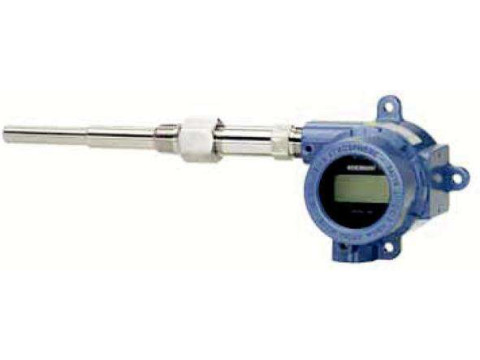
Датчики температуры Rosemount 644, Rosemount 3144Р (далее — датчики температуры или датчики) предназначены для измерений температуры жидких, твердых и газообразных сред.
Скачать
Информация по Госреестру
| Основные данные | |
|---|---|
| Номер по Госреестру | 63889-16 |
| Наименование | Датчики температуры |
| Модель | Rosemount 644, Rosemount 3144Р |
| Межповерочный интервал / Периодичность поверки | 5 лет для датчиков с сенсорами Pt100 (классов А, В с диапазоном -50 … +300 °С), для датчиков с сенсором К-типа (класса допуска 2 и с диапазоном -40 … +600 °С); 4 года для датчиков с сенсорами Pt100 (классов А, В с диапазоном -196 … +600 °С), для датчиков |
| Срок свидетельства (Или заводской номер) | 12.05.2021 |
Производитель / Заявитель
Назначение
Датчики температуры Rosemount 644, Rosemount 3144Р (далее — датчики температуры или датчики) предназначены для измерений температуры жидких, твердых и газообразных сред.
Описание
Принцип действия датчиков температуры основан на преобразовании преобразователем измерительным сигнала от первичного преобразователя (сенсора) в унифицированный выходной сигнал постоянного тока от 4 до 20 мА (с наложенным на него цифровым частотно-модулированным сигналом по протоколу HART), либо в цифровой выходной сигнал по протоколу FOUNDATION Fieldbus или Profibus PA.
Первичный преобразователь состоит из измерительной вставки с чувствительным элементом (ЧЭ) в виде термопреобразователя сопротивления с НСХ Pt100 по ГОСТ 6651-2009 (МЭК 60751) или преобразователем термоэлектрическим с НСХ К, N, J, E, T, B, R, S по ГОСТ Р 8.585-2001 (МЭК 60584-1), помещенной в защитную арматуру. Первичные преобразователи могут комплектоваться защитными гильзами, изготовленными из нержавеющей стали или специальных материалов.
Преобразователь измерительный конструктивно выполнен в корпусе с расположенными на нем клеммами для подключения первичного преобразователя и вывода выходного сигнала.
Датчики могут быть представлены единой сборкой первичного и измерительного преобразователей, либо отдельными элементами с выносным монтажом измерительного преобразователя.
Входные и выходные цепи в датчиках температуры выполнены без гальванической связи.
Схема внутренних соединений преобразователя измерительного с термопреобразователем сопротивления — 2-х, 3-х, 4-х проводная.
Датчики температуры могут иметь взрывозащищенное исполнение.
Цифровая индикация в процессе измерений может осуществляться с помощью встроенного жидкокристаллического дисплея.
Датчики температуры Rosemount 644, 3144Р могут использоваться с одним или двумя чувствительными элементами, находящимися в общей или отдельных защитных арматурах, в зависимости от исполнения.
Датчики могут использовать согласование первичного преобразователя с индивидуальной статической характеристикой преобразования (ИСХ) функции Каллендара — Ван Дюзена (КВД) и измерительного преобразователя.
Исполнения датчиков соответствуют требованиям Технического регламента Таможенного союза ТР ТС 012/2011 «О безопасности оборудования для работы во взрывоопасных средах». Взрывозащищенность датчиков обеспечивается видами взрывозащиты взрывонепроницаемая оболочка «d», искробезопасная электрическая цепь «i», а также выполнением их конструкции в соответствии с общими требованиями к оборудованию, предназначенному для использования во взрывоопасных средах.
Фотографии общего вида датчиков температуры Rosemount 644, Rosemount 3144Р представлены на рисунках 1, 2.
Рисунок 2 — Общий вид датчика температуры Rosemount 3144P
Рисунок 1 — Общий вид датчика температуры Rosemount 644
Программное обеспечение
Датчики температуры имеют только внутреннее метрологически значимое программное обеспечение (ПО). ПО является фиксированным, незагружаемым и может быть изменено только на предприятии-изготовителе.
Идентификационные данные ПО приведены в таблицах 1-5.
Таблица 1 — Данные ПО «644 HART»
Идентификационные данные (признаки)
Идентификационное наименование ПО
Номер версии (идентификационный номер) ПО
Цифровой идентификатор программного обеспечения
Таблица 2 — Данные ПО «644 Fieldbus»
Идентификационные данные (признаки)
Идентификационное наименование ПО
Номер версии (идентификационный номер) ПО ( )
Цифровой идентификатор программного обеспечения
Таблица 3 — Данные ПО «644 Profibus РА»
Идентификационные данные (признаки)
Идентификационное наименование ПО
Номер версии (идентификационный номер) ПО
Цифровой идентификатор программного обеспечения
Идентификационные данные (признаки)
Идентификационное наименование ПО
Номер версии (идентификационный номер) ПО ( )
Цифровой идентификатор программного обеспечения
Таблица 5 — Данные ПО «3144 Fieldbus»
Идентификационные данные (признаки)
Идентификационное наименование ПО
Номер версии (идентификационный номер) ПО ( )
Цифровой идентификатор программного обеспечения
Примечание к таблицам 1-5: у > — и более поздние версии.
Уровень защиты ПО от непреднамеренных и преднамеренных изменений — «высокий» в соответствии с рекомендацией по метрологии Р 50.2.077-2014: программное обеспечение защищено от преднамеренных изменений с помощью специальных программных средств.
Диапазон измерений температуры, °С
Минимальный интервал измерений, °С
Пределы допускаемого отклонения от НСХ первичного преобразователя (ПП), °С
Пределы допускаемой основной погрешности
приведенная (ЦАП), % (от интервала измерений)
приведенная (ЦАП), % (от интервала измерений)
Источник
Преобразователи измерительные Rosemount 644, Rosemount 3144P
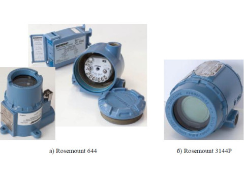
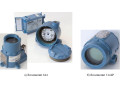

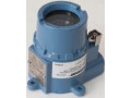
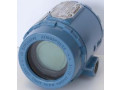
Преобразователи измерительные Rosemount 644, Rosemount 3144P (далее по тексту -ПИ или преобразователи) предназначены для измерения и преобразования сигналов измерительных преобразователей (термопреобразователей сопротивления, преобразователей термоэлектрических и устройств, имеющих на выходе сигналы в виде изменения электрического сопротивления и электрического напряжения постоянного тока) в унифицированный электрический выходной сигнал постоянного тока 4-20 мА, а так же в цифровые сигналы коммуникационных протоколов HART, Foundation fieldbus, Profibus PA (для Rosemount 644) и HART, Foundation fieldbus (для Rosemount 3144Р).
Скачать
Информация по Госреестру
| Основные данные | |
|---|---|
| Номер по Госреестру | 56381-14 |
| Наименование | Преобразователи измерительные |
| Модель | Rosemount 644, Rosemount 3144P |
| Год регистрации | 2014 |
| Методика поверки / информация о поверке | 12.5314.000.00 МП |
| Межповерочный интервал / Периодичность поверки | 5 лет |
| Страна-производитель | СШАГерманияСингапур Россия |
| Информация о сертификате | |
| Срок действия сертификата | 05.02.2019 |
| Тип сертификата (C — серия/E — партия) | C |
| Дата протокола | Приказ 85 п. 43 от 05.02.2014 |
Производитель / Заявитель
Фирмы «Rosemount Inc.», США; «Emerson Process Management GmbH & Co. OHG», Германия; «Emerson Process Management Asia Pacific Pte Ltd.», Сингапур; ЗАО «Промышленная группа «Метран», г.Челябинск
Назначение
Преобразователи измерительные Rosemount 644, Rosemount 3144P (далее по тексту -ПИ или преобразователи) предназначены для измерения и преобразования сигналов измерительных преобразователей (термопреобразователей сопротивления, преобразователей термоэлектрических и устройств, имеющих на выходе сигналы в виде изменения электрического сопротивления и электрического напряжения постоянного тока) в унифицированный электрический выходной сигнал постоянного тока 4-20 мА, а так же в цифровые сигналы коммуникационных протоколов HART, Foundation fieldbus, Profibus PA (для Rosemount 644) и HART, Foundation fieldbus (для Rosemount 3144Р).
Описание
Принцип действия ПИ основан на измерении и преобразовании сигнала измерительного преобразователя в унифицированный выходной сигнал электрического постоянного тока
4-20 мА с наложенным на него цифровым частотно-модулированным сигналом в стандарте протокола HART или в полностью цифровые сигналы Foundation fieldbus (для Rosemount 644 и Rosemount 3144Р), Profibus PA (только для Rosemount 644).
ПИ конструктивно выполнены в корпусе с расположенными на нем клеммами для подачи напряжения питания, подключения входного и выходного сигналов. Преобразователи выполнены на основе микропроцессора и обеспечивают аналого-цифровое преобразование сигнала первичного преобразователя, обработку результатов измерений и их передачу по цифровым интерфейсам и/или по стандартному выходному сигналу 4-20 мА.
ПИ Rosemount 644, Rosemount 3144Р имеют исполнения стандартной и повышенной точности, исполнения, отличающиеся конструкцией, цифровым интерфейсом связи и наличием жидкокристаллического дисплея.
ПИ Rosemount 644 и Rosemount 3144Р могут быть одноканальными или многоканальными.
ПИ могут работать с термопреобразователями сопротивления и термоэлектрическими преобразователями, номинальные статические характеристики преобразования (НСХ) которых указаны в таблице 2, а также с преобразователями, имеющими на выходе сигналы в виде изменения электрического сопротивления или электрического напряжения постоянного тока. Настройку ПИ (тип входного сигнала, диапазон измерений, схему подключения и т.д.) можно изменять, используя полевой коммуникатор или HART-модем и компьютер с установленной программой AMS (для ПИ с цифровыми сигналами Foundation fieldbus и Profibus PA необходимо дополнительное оборудование).
Монтаж ПИ Rosemount 644 может осуществляться в соединительной головке, смонтированной непосредственно вместе с первичным преобразователем, либо отдельно (на монтажном кронштейне). Также ПИ Rosemount 644 имеет исполнение для монтажа на рейке стандарта DIN.
ПИ, в зависимости от исполнения, могут иметь вид взрывозащиты «искробезопасная цепь» и «взрывонепроницаемая оболочка» при монтаже в соединительную головку.
Фото общего вида преобразователей представлено на рисунке 1.
Рисунок 1 — Преобразователи измерительные Rosemount 644, Rosemount 3144P
Программное обеспечение
Программное обеспечение (далее — ПО) ПИ является неизменяемым и несчитываемым. Уровень защиты ПО от преднамеренного и непреднамеренного доступа соответствует уровню «С» по МИ 3286-2010.
Идентификационные данные ПО приведены в таблице 1.
Таблица 1 — Идентификационные данные программного обеспечения
Идентификационное наименование ПО
Номер версии (идентификационный номер) ПО
Цифровой идентификатор ПО (контрольная сумма исполняемого кода)
Алгоритм вычисления цифрового идентификатора ПО
Источник
Датчики температуры Rosemount 644
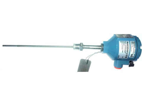
Датчики температуры Rosemount 644 (далее по тексту — датчики температуры или датчики) предназначены для измерений температуры нефтепродуктов в составе системы измерений количества и показателей качества нефти № 814 на ПСП Ярудейского месторождения ООО «ЯРГЕО».
Скачать
Информация по Госреестру
| Основные данные | |
|---|---|
| Номер по Госреестру | 77487-20 |
| Наименование | Датчики температуры |
| Модель | Rosemount 644 |
| Межповерочный интервал / Периодичность поверки | 2 года |
| Страна-производитель | ГЕРМАНИЯ |
| Срок свидетельства (Или заводской номер) | на 10 шт. с зав.№ 02570974/03417259, 02570342/03416935, 02570343/03416936, 02570344/03416937, 02570345/03416938, 02570346/ 03416939, 02570347/03416940, 02570348/03416941, 02570349/03416942, 02570350/03416943 |
Производитель / Заявитель
Фирма «Emerson Process Management GmbH & Co. OHG», Германия
Назначение
Датчики температуры Rosemount 644 (далее по тексту — датчики температуры или датчики) предназначены для измерений температуры нефтепродуктов в составе системы измерений количества и показателей качества нефти № 814 на ПСП Ярудейского месторождения ООО «ЯРГЕО».
Описание
Принцип действия датчиков температуры основан на преобразовании измерительным преобразователем сигнала от первичного преобразователя температуры в унифицированный выходной сигнал постоянного тока от 4 до 20 мА с наложенным на него цифровым частотно-модулированным сигналом по протоколу HART.
Датчики температуры Rosemount 644 состоят из термопреобразователя сопротивления Rosemount 0065 (далее — ТСП) и преобразователя измерительного Rosemount 644H (далее -ИП), помещенного в соединительную головку, смонтированную непосредственно вместе с ТСП.
ТСП выполнен в виде измерительной вставки с одним ЧЭ, имеющим номинальную статистическую характеристику преобразования (НСХ) типа «Pt100» по ГОСТ 6651-2009 (МЭК 60751). Каждый ТСП дополнительно отградуирован и имеет индивидуальные коэффициенты интерполяционной функции Каллендара — Ван Дюзена (ИСХ функции КВД), которые введены в память ИП. Схема соединения внутренних проводов с чувствительным элементом (далее -ЧЭ) ТСП — 4-х проводная.
ИП конструктивно выполнен в корпусе с расположенными на нем клеммами для подключения ТСП, подачи напряжения питания и вывода выходного сигнала.
Монтаж датчиков на объекте измерений осуществляется при помощи штуцерного соединения.
Фотография общего вида датчиков температуры Rosemount 644 представлена на рисунке 1.
Пломбирование осуществляют при помощи пломбы, установленной на контровочной проволоке, охватывающей через пазы крышку корпуса, или при помощи пломбировочной мастики, нанесенной на винт, фиксирующий крышку корпуса.
Схема пломбировки от несанкционированного доступа, представлена на рисунке 2.
Рисунок 2 — Общий вид схемы пломбировки
Программное обеспечение
Датчики температуры имеют только внутреннее метрологически значимое программное обеспечение (ПО). ПО является фиксированным, незагружаемым и может быть изменено только на предприятии-изготовителе.
Идентификационные данные ПО приведены в таблице 1.
Идентификационные данные (признаки)
Идентификационное наименование ПО
Номер версии (идентификационный номер) ПО
Цифровой идентификатор программного обеспечения
Уровень защиты ПО от непреднамеренных и преднамеренных изменений — «высокий» для встроенного ПО в соответствии с рекомендацией по метрологии Р 50.2.077-2014.
Технические характеристики
Метрологические характеристики датчиков температуры Rosemount 644 приведены в таблице 2.
Диапазон измерений температуры, °С
Пределы допускаемого отклонения сопротивления ТСП от ИСХ функции КВД (в температурном эквиваленте), ДТСП, °С
Пределы допускаемой основной абсолютной погрешности аналого-цифрового преобразования (АЦП) ИП, ДАЦП, °С
Пределы допускаемой основной абсолютной погрешности цифро-аналогового преобразования (ЦАП) ИП, ДЦАП, °С
Пределы допускаемой дополнительной абсолютной погрешности от изменения температуры окружающей среды цифрового сигнала1^ °С/1 °С
Пределы допускаемой дополнительной абсолютной погрешности от изменения температуры окружающей среды ЦАП2), °С/1 °С
1. Пределы допускаемой основной абсолютной погрешности датчиков вычисляются по формуле:
— для цифрового выходного сигнала: Д=
— для аналогового выходного сигнала: Д =±лР J
ДТСП — предел допускаемого отклонения сопротивления ТСП от ИСХ температурном эквиваленте), °С;
ДАЦП — предел допускаемой основной абсолютной погрешности АЦП ИП, ДЦАП — предел допускаемой основной абсолютной погрешности ЦАП ИП,
2. 1) — при отклонении температуры окружающей среды от плюс (20±1) °С.
3. 2) — относится к аналоговому выходному сигналу с диапазоном от 4 до 20
Основные технические характеристики датчиков температуры Rosemount 644 приведены в таблице 3.
Напряжение питания постоянного тока, В
Габаритные размеры соединительной головки датчиков (длина х ширина х высота), мм
Длина монтажной части датчиков, мм:
— зав. №№ 02570974/03417259, 02570342/03416935, 02570343/03416936, 02570344/03416937, 02570345/03416938, 02570346/ 03416939, 02570347/03416940
— зав. №№ 02570348/03416941, 02570349/03416942
Диаметр монтажной части датчиков, мм
Рабочие условия эксплуатации:
— температура окружающей среды, °С
— относительная влажность окружающего воздуха, %, не более
Средний срок службы, лет, не менее
Знак утверждения типа
наносится на титульный лист паспорта методом штемпелевания.
Комплектность
Комплектность датчика приведена в таблице 4.
Датчик температуры Rosemount 644
Методика поверки МП 207-025-2019
Поверка
осуществляется по документу МП 207-025-2019 «Датчики температуры Rosemount 644. Методика поверки», утвержденному ФГУП «ВНИИМС» 11.09.2019 г.
Основные средства поверки:
Рабочий эталон 3-го разряда по ГОСТ 8.558-2009 — термометр сопротивления эталонный ЭТС-100/1 (Регистрационный № 19916-10);
Измеритель температуры многоканальный прецизионный МИТ 8 (мод. МИТ 8.15), (Регистрационный № 19736-11);
Термостаты жидкостные ТЕРМОТЕСТ (Регистрационный № 39300-08);
Меры электрического сопротивления однозначные МС3050М (Регистрационный № 46843-11);
Преобразователь сигналов ТС и ТП прецизионный Теркон (Регистрационный № 23245-08);
Калибратор многофункциональный и коммуникатор BEAMEX MC6(-R) (Регистрационный № 52489-13).
Допускается применение средств поверки, обеспечивающих определение метрологических характеристик поверяемых СИ с требуемой точностью.
Знак поверки наносится в паспорт и (или) на свидетельство о поверке.
Сведения о методах измерений
Нормативные документы, устанавливающие требования к датчикам температуры Rosemount 644
ГОСТ 6651-2009 ГСИ. Термопреобразователи сопротивления из платины, меди и никеля. Общие технические требования и методы испытаний
Международный стандарт МЭК 60751 (2008, 07) Промышленные чувствительные элементы термометров сопротивления из платины
ГОСТ Р 52931-2008 Приборы контроля и регулирования технологических процессов. Общие технические условия
ГОСТ 8.558-2009 ГСИ. Государственная поверочная схема для средств измерений температуры
Источник