Инструкция для GPS/GNSS приемника Topcon HiPer SR
![]()
Руководство по эксплуатации GPS/GNSS приемника Topcon HiPer SR
| Имя файла: | topcon_hiper_sr.pdf |
| Размер файла: | 3 MB |
| Тип файла: | application/pdf |
| Посещений: | 4414 Посещений |
| Дата последнего обновления: | 16-12-15 |
-
Скачать -
Просмотр
- Manuals
- Brands
- Topcon Manuals
- Receiver
- HiPer SR
- Operator’s manual
-
Contents
-
Table of Contents
-
Troubleshooting
-
Bookmarks
Quick Links
Related Manuals for Topcon HiPer SR
Summary of Contents for Topcon HiPer SR
-
Page 2
HiPer SR Operator’s Manual Part Number 1000737‐01 Rev C ECO#000187 ©Copyright Topcon Positioning Systems, Inc. December, 2013 All contents in this manual are copyrighted by Topcon Positioning Systems, Inc. All rights reserved. -
Page 4: Preface
Preface • • • • • • Thank you for purchasing this Topcon product. The materials available in this Manual (the “Manual”) have been prepared by Topcon Positioning Systems, Inc. (“TPS”) for owners of Topcon products, and are designed to assist owners with the use of the receiver and its use is subject to these terms and conditions (the “Terms and Conditions”). Please read the terms and conditions carefully. Terms and Conditions This product is designed to be used by a professional. The user should have a good knowledge of the safe use of the product and implement the types of safety procedures recommended by the local government protection agency for both private use and commercial job sites. Preface P/N: 1000737‐01 i …
-
Page 5: Copyrights
Copyrights All information contained in this Manual is the intellectual property of, and copyrighted material of TPS. All rights are reserved. Do not use, access, copy, store, display, create derivative works of, sell, modify, publish, distribute, or allow any third party access to, any graphics, content, information or data in this Manual without TPS’ express written consent and may only use such information for the care and operation of the receiver. The information and data in this Manual are a valuable asset of TPS and are developed by the expenditure of considerable work, time and money, and are the result of original selection, coordination and arrangement by TPS. Trademarks HiPer SR™, TRU™, Magnet™, Pocket‐3D™, Topcon® and Topcon Positioning Systems™ are trademarks or registered trademarks of TPS. Windows® is a registered trademark of Microsoft Corporation. The Bluetooth® word mark and logos are owned by Bluetooth SIG, Inc. and any use of such marks by Topcon Positioning Systems, Inc. is used under license. Other product and company names mentioned herein may be trademarks of their respective owners. Disclaimer of Warranty EXCEPT FOR ANY WARRANTIES IN AN APPENDIX OR A WARRANTY CARD ACCOMPANYING THE PRODUCT, THIS MANUAL AND THE RECEIVER ARE PROVIDED “AS‐IS.” THERE ARE NO OTHER WARRANTIES. TPS DISCLAIMS ANY IMPLIED WARRANTY OF MERCHANTABILITY OR FITNESS FOR ANY PARTICULAR USE OR PURPOSE. TPS AND ITS DISTRIBUTORS SHALL NOT BE LIABLE FOR TECHNICAL OR EDITORIAL ERRORS OR OMISSIONS CONTAINED HEREIN; NOR FOR INCIDENTAL OR CONSEQUENTIAL DAMAGES RESULTING FROM THE FURNISHING, PERFORMANCE OR USE OF THIS MATERIAL OR THE RECEIVER. SUCH DISCLAIMED DAMAGES INCLUDE BUT ARE NOT LIMITED TO LOSS OF TIME, LOSS OR DESTRUCTION OF DATA, LOSS OF PROFIT, SAVINGS OR REVENUE, OR LOSS OF THE PRODUCT’S USE. IN ADDITION TPS IS NOT RESPONSIBLE OR LIABLE FOR DAMAGES OR COSTS P/N: 1000737‐01 ii Terms and Conditions …
-
Page 6: License Agreement
INCURRED IN CONNECTION WITH OBTAINING SUBSTITUTE PRODUCTS OR SOFTWARE, CLAIMS BY OTHERS, INCONVENIENCE, OR ANY OTHER COSTS. IN ANY EVENT, TPS SHALL HAVE NO LIABILITY FOR DAMAGES OR OTHERWISE TO YOU OR ANY OTHER PERSON OR ENTITY IN EXCESS OF THE PURCHASE PRICE FOR THE RECEIVER. License Agreement Use of any computer programs or software supplied by TPS or downloaded from a TPS website (the “Software”) in connection with the receiver constitutes acceptance of these Terms and Conditions in this Manual and an agreement to abide by these Terms and Conditions. The user is granted a personal, non‐exclusive, non‐transferable license to use such Software under the terms stated herein and in any case only with a single receiver or single computer. You may not assign or transfer the Software or this license without the express written consent of TPS. This license is effective until terminated. You may terminate the license at any time by destroying the Software and Manual. TPS may terminate the license if you fail to comply with any of the Terms or Conditions. You agree to destroy the Software and manual upon termination of the use of the receiver. All ownership, copyright and other intellectual property rights in and to the Software belong to TPS. If these license terms are not acceptable, return any unused software and manual. Confidentiality This Manual, its contents and the Software (collectively, the “Confidential Information”) are the confidential and proprietary information of TPS. You agree to treat TPS’ Confidential Information with a degree of care no less stringent that the degree of care you would use in safeguarding your own most valuable trade secrets. Nothing in this paragraph shall restrict you from disclosing Confidential Information to your employees as may be necessary or appropriate to operate or care for the receiver. Such employees must also keep the Confidentiality Information confidential. In the event you become legally compelled to disclose any of the Confidential Information, you shall give TPS immediate notice so that it may seek a protective order or other appropriate remedy. P/N: 1000737‐01 iii Terms and Conditions …
-
Page 7: Website; Other Statements
Website; Other Statements No statement contained at the TPS website (or any other website) or in any other advertisements or TPS literature or made by an employee or independent contractor of TPS modifies these Terms and Conditions (including the Software license, warranty and limitation of liability). Safety Improper use of the receiver can lead to injury to persons or property and/or malfunction of the product. The receiver should only be repaired by authorized TPS warranty service centers. Users should review and heed the safety warnings in an Appendix. Miscellaneous The above Terms and Conditions may be amended, modified, superseded, or canceled, at any time by TPS. The above Terms and Conditions will be governed by, and construed in accordance with, the laws of the State of California, without reference to conflict of laws. P/N: 1000737‐01 iv Terms and Conditions …
-
Page 8: Manual Conventions
Manual Conventions This manual uses the following conventions: Convention Description Example Bold Menu, or drop‐down menu selection FileExit (Click the File menu and click Exit) Name of a dialog box or screen From the Connection screen… Button or key commands Click Finish. User supplied text or variable Type guest, and click Enter. Mono Italic Reference to another manual or help document Refer to the Topcon Reference Manual. Further information to note about system configuration, maintenance, or setup. Supplementary information that can have an adverse affect on system operation, system performance, data integrity, measurements, or personal safety. Notification that an action has the potential to result in system damage, loss of data, loss of warranty, or personal injury. P/N: 1000737‐01 v Terms and Conditions …
-
Page 9: Table Of Contents
Table of Contents • • • • • • Preface . . . . . . . . . . . . . . . . . . . . . . . . . . . . . . . . . . . . . . . . . . . . . . . . . . . . . . . . . . . . . . . . . . i Terms and Conditions. . . . . . . . . . . . . . . . . . . . . . . . . . . . . . . . . . . . . . . . . . . . . . . . . . . . . . . . . . . . i Use. . . . . . . . . . . . . . . . . . . . . . . . . . . . . . . . . . . . . . . . . . . . . . . . . . . . . . . . . . . . . . . . . . . . . . . . i Copyrights . . . . . . . . . . . . . . . . . . . . . . . . . . . . . . . . . . . . . . . . . . . . . . . . . . . . . . . . . . . . . . . . . . ii Trademarks . . . . . . . . . . . . . . . . . . . . . . . . . . . . . . . . . . . . . . . . . . . . . . . . . . . . . . . . . . . . . . . . . ii Disclaimer of Warranty . . . . . . . . . . . . . . . . . . . . . . . . . . . . . . . . . . . . . . . . . . . . . . . . . . . . . . . ii License Agreement. . . . . . . . . . . . . . . . . . . . . . . . . . . . . . . . . . . . . . . . . . . . . . . . . . . . . . . . . . . iii Confidentiality . . . . . . . . . . . . . . . . . . . . . . . . . . . . . . . . . . . . . . . . . . . . . . . . . . . . . . . . . . . . . . iii Website; Other Statements. . . . . . . . . . . . . . . . . . . . . . . . . . . . . . . . . . . . . . . . . . . . . . . . . . . . iv Safety . . . . . . . . . . . . . . . . . . . . . . . . . . . . . . . . . . . . . . . . . . . . . . . . . . . . . . . . . . . . . . . . . . . . . iv Miscellaneous. . . . . . . . . . . . . . . . . . . . . . . . . . . . . . . . . . . . . . . . . . . . . . . . . . . . . . . . . . . . . . . iv Manual Conventions . . . . . . . . . . . . . . . . . . . . . . . . . . . . . . . . . . . . . . . . . . . . . . . . . . . . . . . . . v Introduction . . . . . . . . . . . . . . . . . . . . . . . . . . . . . . . . . . . . . . . . . . . . . . . . . . . . . . . . . . . . . 1 P/N: 1000737‐01 vi …
-
Page 10
HiPer SR Features . . . . . . . . . . . . . . . . . . . . . . . . . . . . . . . . . . . . . . . . . . . . . . . . . . . . . . . . . . . . . . . 2 Unpacking Your Receiver Kit . . . . . . . . . . . . . . . . . . . . . . . . . . . . . . . . . . . . . . . . . . . . . . . . . . . . . . 3 System Components . . . . . . . . . . . . . . . . . . . . . . . . . . . . . . . . . . . . . . . . . . . . . . . . . . . . . . . . . 4 Accessories . . . . . . . . . . . . . . . . . . . . . . . . . . . . . . . . . . . . . . . . . . . . . . . . . . . . . . . . . . . . . . . . . 5 Technical Documents . . . . . . . . . . . . . . . . . . . . . . . . . . . . . . . . . . . . . . . . . . . . . . . . . . . . . . . . . . . . 5 Using Topcon Software With Your Receiver . . . . . . . . . . . . . . . . . . . . . . . . . . . . . . . . . . . . . . . . . . 6 Getting Technical Support . . . . . . . . . . . . . . . . . . . . . . . . . . . . . . . . . . . . . . . . . . . . . . . . . . . . . . . . 7 Website . . . . . . . . . . . . . . . . . . . . . . . . . . . . . . . . . . . . . . . . . . . . . . . . . . . . . . . . . . . . . . . . . . . . 8 Getting Acquainted . . . . . . . . . . . . . . . . . . . . . . . . . . . . . . . . . . . . . . . . . . . . . . . . . . . . . . . . 9 Receiver Overview . . . . . . . . . . . . . . . . . . . . . . . . . . . . . . . . . . . . . . . . . . . . . . . . . . . . . . . . . . . . . . 9 Basic Receiver Housing Overview . . . . . . . . . . . . . . . . . . . . . . . . . . . . . . . . . . . . . . . . . . . . . . . 10 HiPer SR Cellular Housing Overview . . . . . . . . . . . . . . . . . . . . . . . . . . . . . . . . . . . . . . . . . . . . . 11 Cables. . . . . . . . . . . . . . . . . . . . . . . . . . . . . . . . . . . . . . . . . . . . . . . . . . . . . . . . . . . . . . . . . . . . . . . . . 12 Memory . . . . . . . . . . . . . . . . . . . . . . . . . . . . . . . . . . . . . . . . . . . . . . . . . . . . . . . . . . . . . . . . . . . . . . . 14 SIM Card Slots (Option) . . . . . . . . . . . . . . . . . . . . . . . . . . . . . . . . . . . . . . . . . . . . . . . . . . . . . . . . . . 14 Internal Batteries . . . . . . . . . . . . . . . . . . . . . . . . . . . . . . . . . . . . . . . . . . . . . . . . . . . . . . . . . . . . . . . 15 LongLINK Wireless Communication. . . . . . . . . . . . . . . . . . . . . . . . . . . . . . . . . . . . . . . . . . . . . . . . . 15 P/N: 1000737‐01 vii … -
Page 11
Cellular Communication (Option) . . . . . . . . . . . . . . . . . . . . . . . . . . . . . . . . . . . . . . . . . . . . . . . . . . 15 Ports Panel. . . . . . . . . . . . . . . . . . . . . . . . . . . . . . . . . . . . . . . . . . . . . . . . . . . . . . . . . . . . . . . . . . . . . 16 Display Panel Operations . . . . . . . . . . . . . . . . . . . . . . . . . . . . . . . . . . . . . . . . . . . . . . . . . . . 17 Power Button . . . . . . . . . . . . . . . . . . . . . . . . . . . . . . . . . . . . . . . . . . . . . . . . . . . . . . . . . . . . . . . . . . 18 Receiver Status LEDs. . . . . . . . . . . . . . . . . . . . . . . . . . . . . . . . . . . . . . . . . . . . . . . . . . . . . . . . . . . . . 19 Tracking Status LED . . . . . . . . . . . . . . . . . . . . . . . . . . . . . . . . . . . . . . . . . . . . . . . . . . . . . . . . . . 19 Recording LED. . . . . . . . . . . . . . . . . . . . . . . . . . . . . . . . . . . . . . . . . . . . . . . . . . . . . . . . . . . . . . . 20 Communication LED. . . . . . . . . . . . . . . . . . . . . . . . . . . . . . . . . . . . . . . . . . . . . . . . . . . . . . . . . . 21 Bluetooth Only Status 21 Cellular and Bluetooth Status 21 Cellular Status 23 Battery LED . . . . . . . . . . . . . . . . . . . . . . . . . . . . . . . . . . . . . . . . . . . . . . . . . . . . . . . . . . . . . . . . . 24 Managing Power . . . . . . . . . . . . . . . . . . . . . . . . . . . . . . . . . . . . . . . . . . . . . . . . . . . . . . . . . . 25 Turning On/Off the Receiver . . . . . . . . . . . . . . . . . . . . . . . . . . . . . . . . . . . . . . . . . . . . . . . . . . . . . . 25 Using Internal and External Power Sources . . . . . . . . . . . . . . . . . . . . . . . . . . . . . . . . . . . . . . . . . . 25 Internal Batteries . . . . . . . . . . . . . . . . . . . . . . . . . . . . . . . . . . . . . . . . . . . . . . . . . . . . . . . . . . . . 26 Charging the Batteries . . . . . . . . . . . . . . . . . . . . . . . . . . . . . . . . . . . . . . . . . . . . . . . . . . . . . . . . 27 Insufficient Power . . . . . . . . . . . . . . . . . . . . . . . . . . . . . . . . . . . . . . . . . . . . . . . . . . . . . . . . . . . . . . . 28 P/N: 1000737‐01 viii … -
Page 12
Configuring the Receiver . . . . . . . . . . . . . . . . . . . . . . . . . . . . . . . . . . . . . . . . . . . . . . . . . . . 30 Viewing Receiver Information . . . . . . . . . . . . . . . . . . . . . . . . . . . . . . . . . . . . . . . . . . . . . . . . . . . . . 30 Loading New Firmware. . . . . . . . . . . . . . . . . . . . . . . . . . . . . . . . . . . . . . . . . . . . . . . . . . . . . . . . . . . 32 About the OAF. . . . . . . . . . . . . . . . . . . . . . . . . . . . . . . . . . . . . . . . . . . . . . . . . . . . . . . . . . . . . . . . . . 40 Checking the Receiver’s OAF. . . . . . . . . . . . . . . . . . . . . . . . . . . . . . . . . . . . . . . . . . . . . . . . . . . 40 Loading an OAF. . . . . . . . . . . . . . . . . . . . . . . . . . . . . . . . . . . . . . . . . . . . . . . . . . . . . . . . . . . . . . 41 Resetting the Receiver (Clearing the NVRAM) . . . . . . . . . . . . . . . . . . . . . . . . . . . . . . . . . . . . . . . . 44 Using the Reset Button. . . . . . . . . . . . . . . . . . . . . . . . . . . . . . . . . . . . . . . . . . . . . . . . . . . . . . . . . . . 45 Field System Setup . . . . . . . . . . . . . . . . . . . . . . . . . . . . . . . . . . . . . . . . . . . . . . . . . . . . . . . . 47 Setting Up the Base Receiver . . . . . . . . . . . . . . . . . . . . . . . . . . . . . . . . . . . . . . . . . . . . . . . . . . . . . . 48 Setting Up the Rover Receiver . . . . . . . . . . . . . . . . . . . . . . . . . . . . . . . . . . . . . . . . . . . . . . . . . . . . . 50 Measuring Antenna Height . . . . . . . . . . . . . . . . . . . . . . . . . . . . . . . . . . . . . . . . . . . . . . . . . . . . . . . 52 Collecting Data . . . . . . . . . . . . . . . . . . . . . . . . . . . . . . . . . . . . . . . . . . . . . . . . . . . . . . . . . . . 54 Setting Recording Parameters . . . . . . . . . . . . . . . . . . . . . . . . . . . . . . . . . . . . . . . . . . . . . . . . . . . . . 54 Logging Rates. . . . . . . . . . . . . . . . . . . . . . . . . . . . . . . . . . . . . . . . . . . . . . . . . . . . . . . . . . . . . . . . . . . 54 Recording Data . . . . . . . . . . . . . . . . . . . . . . . . . . . . . . . . . . . . . . . . . . . . . . . . . . . . . . . . . . . . . . . . . 54 Managing Files. . . . . . . . . . . . . . . . . . . . . . . . . . . . . . . . . . . . . . . . . . . . . . . . . . . . . . . . . . . . . . . . . . 55 P/N: 1000737‐01 ix … -
Page 13
Downloading and Deleting Files . . . . . . . . . . . . . . . . . . . . . . . . . . . . . . . . . . . . . . . . . . . . . . . . 56 Troubleshooting . . . . . . . . . . . . . . . . . . . . . . . . . . . . . . . . . . . . . . . . . . . . . . . . . . . . . . . . . . 57 Check This First! . . . . . . . . . . . . . . . . . . . . . . . . . . . . . . . . . . . . . . . . . . . . . . . . . . . . . . . . . . . . . . . . 57 Powering Problems. . . . . . . . . . . . . . . . . . . . . . . . . . . . . . . . . . . . . . . . . . . . . . . . . . . . . . . . . . . . . . 58 Receiver Problems . . . . . . . . . . . . . . . . . . . . . . . . . . . . . . . . . . . . . . . . . . . . . . . . . . . . . . . . . . . . . . 59 LongLINK Problems . . . . . . . . . . . . . . . . . . . . . . . . . . . . . . . . . . . . . . . . . . . . . . . . . . . . . . . . . . . . . . 62 Bluetooth Problems . . . . . . . . . . . . . . . . . . . . . . . . . . . . . . . . . . . . . . . . . . . . . . . . . . . . . . . . . . . . . 63 TRU Problems . . . . . . . . . . . . . . . . . . . . . . . . . . . . . . . . . . . . . . . . . . . . . . . . . . . . . . . . . . . . . . . . . . 65 Cleaning and Storing the Receiver. . . . . . . . . . . . . . . . . . . . . . . . . . . . . . . . . . . . . . . . . . . . . . . . . . 66 Getting Customer Support . . . . . . . . . . . . . . . . . . . . . . . . . . . . . . . . . . . . . . . . . . . . . . . . . . . . . . . . 66 Specifications . . . . . . . . . . . . . . . . . . . . . . . . . . . . . . . . . . . . . . . . . . . . . . . . . . . . . . . . . . . . 67 General Details . . . . . . . . . . . . . . . . . . . . . . . . . . . . . . . . . . . . . . . . . . . . . . . . . . . . . . . . . . . . . . . . . 67 Safety Warnings . . . . . . . . . . . . . . . . . . . . . . . . . . . . . . . . . . . . . . . . . . . . . . . . . . . . . . . . . . 74 General Warnings . . . . . . . . . . . . . . . . . . . . . . . . . . . . . . . . . . . . . . . . . . . . . . . . . . . . . . . . . . . . . . 74 Receiver Warnings . . . . . . . . . . . . . . . . . . . . . . . . . . . . . . . . . . . . . . . . . . . . . . . . . . . . . . . . . . . . . . 75 Usage Warnings . . . . . . . . . . . . . . . . . . . . . . . . . . . . . . . . . . . . . . . . . . . . . . . . . . . . . . . . . . . . . . . . 75 Regulatory . . . . . . . . . . . . . . . . . . . . . . . . . . . . . . . . . . . . . . . . . . . . . . . . . . . . . . . . . . . . . . . 76 P/N: 1000737‐01 x … -
Page 14
FCC Compliance. . . . . . . . . . . . . . . . . . . . . . . . . . . . . . . . . . . . . . . . . . . . . . . . . . . . . . . . . . . . . . . . . 76 Industry Canada Compliance . . . . . . . . . . . . . . . . . . . . . . . . . . . . . . . . . . . . . . . . . . . . . . . . . . . . . . 77 Community of Europe Compliance . . . . . . . . . . . . . . . . . . . . . . . . . . . . . . . . . . . . . . . . . . . . . . . . . 78 European Community Declaration of Conformity with R&TTE Directive 1999/5/EC . . . . . . 78 Declaration of Conformity (R&TTE Directive 1999/5/EC) . . . . . . . . . . . . . . . . . . . . . . . . . . . . . . . 79 WEEE Directive . . . . . . . . . . . . . . . . . . . . . . . . . . . . . . . . . . . . . . . . . . . . . . . . . . . . . . . . . . . . . . . . . 83 Bluetooth Transmission Statements/Compliance . . . . . . . . . . . . . . . . . . . . . . . . . . . . . . . . . . . . . 83 Korean KC‐RF Compliance . . . . . . . . . . . . . . . . . . . . . . . . . . . . . . . . . . . . . . . . . . . . . . . . . . . . . . . . 84 Glossary . . . . . . . . . . . . . . . . . . . . . . . . . . . . . . . . . . . . . . . . . . . . . . . . . . . . . . . . . . . . . . . . . 85 P/N: 1000737‐01 xi … -
Page 15: Introduction
Introduction • • • • • • Topcon’s HiPer SR receiver is a compact, lightweight, and completely integrated GNSS receiver for static and cable‐free stop‐and‐ go/kinematic applications. The integrated receiver design includes a GNSS receiver board based on Vanguard™ technology, industry leading Fence Antenna™, internal long‐life batteries, memory storage, and Topcon’s innovative LongLINK™ and cellular wireless communication technology. The HiPer SR delivers world‐class positioning and navigation capability to your application by tracking signals from multi‐constellation satellite systems, including GPS, GLONASS, and SBAS. Topcon offers two models of the HiPer SR receiver: Basic and Cellular. The Basic receiver includes Topcon’s exclusive LongLINK communication technology, which provides the perfect small job site system suitable for short range (up to 300m from the Base station) RTK communication. The Cellular model includes LongLINK technology and an expanded range (where cellular coverage is provided) for long‐distance RTK communication. Using the Cellular receiver, you can set up a Base or Rover network with up to 10?? receivers??? The HiPer SR offers complete IP67 protection against dust and water ingress, in addition to superior vibration and shock resistance. The Topcon communication interface allows you to quickly integrate Topcon’s premium GNSS performance within new systems and quickly deliver world‐class positioning and navigation support to your applications. Introduction P/N: 1000737‐01 1 …
-
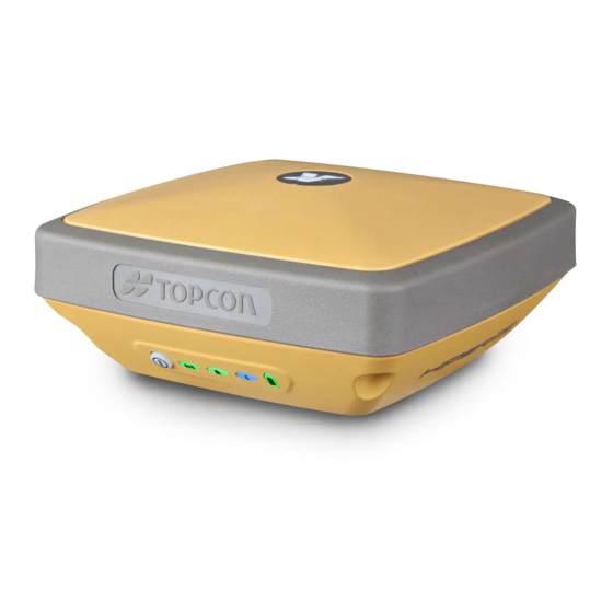
Page 16: Hiper Sr Features
Figure 1: HiPer SR Receiver HiPer SR Features The HiPer SR receiver’s advanced design eliminates the need for cables during operation, allowing for a simplified setup and less parts to keep track of. The HiPer SR receiver features the following: • Compact, lightweight, and rugged design • Industry‐leading Fence Antenna™ technology • A premier multi‐constellation Vanguard™ technology GNSS board P/N: 1000737‐01 2 HiPer SR Features …
-
Page 17: Unpacking Your Receiver Kit
(Cellular) Integrated cellular modem for independent and cable‐free network operation • (Cellular) Dual SIM operation to allow use of two services • 8 GB internal memory • Internal batteries, providing at least 15 hours of operation in any configuration • A highly visible display panel with single‐button operation • USB and power/RS‐232 ports You can configure the HiPer SR receiver in a variety of ways, depending on your project requirements. Typically, the receiver supports the following operation modes: • Static post‐processing • LongLINK Base and Rover RTK • Network Rover RTK • Network Base RTK • SBAS‐enabled navigation Unpacking Your Receiver Kit This section describes the documentation, standard kit components, and accessories (depending on your purchase) that accompany your receiver. When you unpack your receiver kit, verify you received the items listed in this section. Make sure the items do not appear damaged from shipment. If any of the items are missing or damaged, contact your Topcon dealer or Topcon technical support. See “Getting Technical Support” on page 7. • Standard components are illustrated in Figure 2. • Receiver accessories are illustrated in Figure 3. • Receiver documentation is listed on page 5. P/N: 1000737‐01 3 Unpacking Your Receiver Kit …
-
Page 18: System Components
System Components The items illustrated in Figure 2 are included with your receiver. Figure 2: Standard System Components The GPS+ Software CD includes USB drivers, which you need to install to use the USB port for communications. P/N: 1000737‐01 4 Unpacking Your Receiver Kit …
-
Page 19: Accessories
Accessories Topcon offers a wide variety of accessories (see Figure 3) specially designed to improve system flexibility and job site efficiency. For more details on the optional accessories available for HiPer SR, contact your Topcon dealer. Figure 3: Receiver Accessories Technical Documents The HiPer SR Manual CD includes two manuals (listed below) that help you set up and use your new receiver quickly and efficiently. • HiPer SR Operator’s Manual – An on‐screen help document that contains detailed information on how to use your new receiver. • Topcon Receiver Utility (TRU) Reference Guide – An on‐screen help document that contains detailed information on how to use the TRU software included on the GPS+ Software CD. For more information about the TRU software, see “Using Topcon Software With Your Receiver”. P/N: 1000737‐01 5 Technical Documents …
-
Page 20: Using Topcon Software With Your Receiver
Using Topcon Software With Your Receiver Use the HiPer SR receiver in conjunction with the Topcon Receiver Utility (TRU) and MAGNET Field™ or Pocket‐3D applications for a cable‐free positioning solution. Topcon software enables you to configure the receiver and other external devices, manage files, collect data, and perform survey and construction work flows. The Topcon Receiver Utility (TRU) is a hardware configuration software for receivers and peripheral devices. You can install it on desktop computers and data controllers. This program is provided on the GPS+ Software CD that accompanied your receiver. A TRU help document is provided on the HiPer SR CD. Topcon’s MAGNET Field™ software for data controllers provides real‐time communication, cloud storage, data collection and exchange, and field solutions, such as topo, staking, roads, calculations, and more. Contact your Topcon dealer for more information about MAGNET Field and the entire MAGNET Enterprise system. Pocket‐3D is a program that runs on data controllers with Windows CE® and mobile platforms. Pocket‐3D simplifies data collection, allowing you to check cuts and fills, layout points and survey all or part of the job site quickly and efficiently. Contact your Topcon dealer for more information about Pocket‐3D. Magnet Relay™ is a GNSS correction service hosted by the MAGNET Solution. With a subscription to MAGNET Relay, you can connect the HiPer SR Cellular receiver to the Relay service (via a cellular connection) and use it as a Base for up to 10 Rovers. P/N: 1000737‐01 6 Using Topcon Software With Your Receiver …
-
Page 21: Getting Technical Support
Getting Technical Support Before contacting a Topcon customer representative about any problems with the receiver, see “Troubleshooting” on page 57 for some solutions that may fix the issue. Contact your local Topcon dealer or visit the Topcon Total Care Web site (www.TopconTotalCare.com) for technical support. For quick and effective support, provide a detailed description of the problem. When contacting Topcon for technical assistance, provide the following information for better and faster service: 1. A description of the following: – Field operation that was being performed when the problem occurred – Details of the unexpected behavior, symptoms, and any error messages that precede or follow the problem – Problem occurrence frequency or patterns 2. Receiver information and configuration settings. For receiver information, click Information in TRU, select Save to File, enter a file name, and save it to the computer. 3. Specifications of mobile devices and computers used in the field or office exhibiting the problem. These specifications should include model information, version number, operating system information, memory and storage capacity, etc. 4. Information about the system software, including the version number and steps to reproduce the problem. 5. A description of the field environment and/or observation conditions when the problem occurred. P/N: 1000737‐01 7 Getting Technical Support …
-
Page 22: Website
Website The Topcon website provides current information about Topcon’s line of products. The support area of the website provides access to Topcon field and office software, manuals, frequently asked questions, and so forth. To access the Topcon website, visit www.topconpositioning.com. The Topcon’s TotalCare web site also provides complete support, such as news, updates, reminders, training, live Webinars, and customer service to help you get the information you need. Visit www.topcontotalcare.com. P/N: 1000737‐01 8 Getting Technical Support …
-
Page 23: Getting Acquainted
Getting Acquainted • • • • • • The HiPer SR receiver enclosure is fully sealed and incorporates the GNSS receiver board, antenna, batteries, memory storage, and wireless communication device. Receiver Overview The upper portion of the receiver contains GNSS and LongLINK antennas enclosed by the radome, which is securely surrounded by a shock‐absorbing rubber bumper. An easy‐to‐operate display panel, mounting socket, and labels with receiver information are located on the bottom of the receiver’s magnesium alloy lower enclosure. The HiPer SR receiver has a highly‐visible display panel with single‐button operation. The display panel enables you to view the receiver’s operational status. For more information, see “Display Panel Operations” on page 17. The mounting socket (Figure 4) connects the receiver to either a standard 5/8» thread pole or adapter. You can locate regulatory and product identification information on the two receiver labels. The product identification label contains the serial number and part number along with a quick response (QR) matrix code. You can scan the QR code with any QR code application on a smart phone and it will open the product information page at the Topcon Total Care website (www.topcontotalcare.com). Getting Acquainted P/N: 1000737‐01 9 …
-
Page 24: Basic Receiver Housing Overview
Basic Receiver Housing Overview LED Display Panel Need New Pic Product ID Label with Part Number and QR Code Serial Number Mounting Socket Rubber Bumper Ports Panel Figure 4: Basic Receiver — Bottom Enclosure Overview P/N: 1000737‐01 10 Receiver Overview …
-
Page 25
HiPer SR Cellular Housing Overview LED Display Panel Need New Pic Product ID Label with Part Number and QR Code Serial Number Mounting Socket Rubber Bumper Ports Panel Figure 5: HiPer SR Cellular Receiver: Bottom Enclosure Overview P/N: 1000737‐01 11 Receiver Overview … -
Page 26: Cables
Cables The HiPer SR package includes a power supply cable, a USB cable, and a power adapter. Table 1 describes the cables included with your receiver. Align the keyways when connecting the power/serial cable to the receiver port. Turn the cable lock clockwise until it clicks to secure the cable in place. To disconnect the cable, turn the lock counter‐clockwise, and then gently remove the cable. Table 1. Receiver Cables Cable Description Cable Illustration Receiver Power Cable Connects the receiver to the power adapter through the SAE connector. p/n: 1000181‐01 USB Cable Connects the receiver to an external device (controller or computer) for data transfer and receiver configuration. p/n 14‐008081‐01 P/N: 1000737‐01 12 Cables …
-
Page 27
Table 1. Receiver Cables Cable Description Cable Illustration Power Adapter Charges the receiver when connected to a grounded outlet and the power charger cable. p/n 22‐034101‐01 Power Charger Cable Connects the power adapter to a grounded outlet. Sever‐ al options are available for the power charger cable based on your country. If the kit does not include a power charger cable, contact your Topcon dealer. Refer to the these part numbers for available power charger cables: p/n 14‐008052‐01 (USA connector) p/n 14‐008054‐01 (EUR connector) p/n 14‐008074‐01 (AUS connector) p/n 1000475‐01 (BRL connector) Power and Serial Cable Connects the receiver to the power adapter through the SAE connector and an external device through the RS‐232 port (DB9 connector). Typically, this cable is not shipped with the standard kit configuration but is available to purchase separately. p/n: 1000182‐01 P/N: 1000737‐01 13 Cables … -
Page 28: Memory
Memory The HiPer SR is equipped with an internal, non‐removable memory card that provides up to 8 GB of data storage. As data is logged to the receiver’s memory, the REC LED displays the memory capacity status. See “Recording LED” on page 20 for more information. To access the raw data files in the receiver’s internal memory, see “Managing Files” on page 55. SIM Card Slots (Option) The HiPer SR Cellular receiver is equipped with two micro‐SIM card slots that allow you to switch from one service provider to another as required. Using dual SIM cards enable you to use two cellular services without the need to swap the SIM card in the field. You can only install micro‐SIM cards into these slots. Once installed, the micro SIM card provides a unique identification for the receiver and enables the receiver’s cellular networking functionality based on the subscribed services. You can purchase a micro‐SIM card from your local cellar provider. Need Picture Figure 6: Receiver Micro SIM Card Slots P/N: 1000737‐01 14 Memory …
-
Page 29: Internal Batteries
Internal Batteries The HiPer SR receiver was designed with two internal, non‐removable batteries, so there is no battery door or connectors to worry about. The batteries are easily charged using the supplied power adapter or an external power source. See “Internal Batteries” on page 26 for more information. LongLINK Wireless Communication The HiPer SR receiver has integrated LongLINK™ wireless technology that enables multiple (up to 3) cable‐free connections to other HiPer SR devices for LongLINK Base/Rover RTK systems. You can also connect the receiver to other Class 1‐ and Class 2‐ enabled Bluetooth devices (such as data collectors and computers) using Bluetooth wireless technology concurrently with LongLINK connections. Topcon’s LongLINK technology enables communication of RTCM3 differential corrections between two HiPer SR receivers over Bluetooth (up to 300 meters), eliminating the need for additional external radios for corrections. For more information, see “Field System Setup” on page 47. Cellular Communication (Option) The cellular integration of the HiPer SR receiver … Place cellular marketing blurb here. P/N: 1000737‐01 15 Internal Batteries …
-
Page 30: Ports Panel
Ports Panel The receiver is equipped with the following ports: • USB – Used for high‐speed data transfer and communication between the receiver and an external device. • Power/Serial — Used for communication between the receiver and an external device. Also used to power the receiver when the internal batteries are not in use. See “Using Internal and External Power Sources” on page 25. • Cellular ANT Connector — Not a GPS Antenna Connector. A TNC connector used to connect the cellular and UHF antenna. Need Pic Figure 7: Receiver Ports Panel P/N: 1000737‐01 16 Ports Panel …
-
Page 31: Display Panel Operations
Display Panel Operations • • • • • • The LED display panel (Figure
 enables you to control receiver power and data recording. The LEDs display the status of the satellite tracking, recording/memory capacity, Bluetooth and LongLINK connections, and batteries. This chapter describes the different LED blink patterns and what they mean. Power Recording Battery (PWR) (REC) (BATT) Status Communication (COMM) (STAT) Figure 8: LED Display Panel Display Panel Operations P/N: 1000737‐01 17 …
 -
Page 32: Power Button
Power Button The power button performs multiple functions. The number of seconds in which the button is pressed and held determines how the receiver will perform. Table 2 describes how to use the power button. Table 2. Power Button Functions FUNCTION PRESS BUTTON LED DESCRIPTION Power On 1+ seconds Power LED blinks green until the startup is complete, and then the LED turns off. Power Off 3‐10 seconds All LEDs are off. Release the Power button when the Battery LED is solid red. Factory Reset 10‐15 seconds All LEDs are off. Release the Power button when the Status LED is solid red. Clear NVRAM Erase All Files 15‐20 seconds All LEDs are off. Release the Power button when the Recording LED is solid red. Note: This action is irreversible. If you are unsure about this action, continue to hold down the button until all LEDs return to normal. Disregard More than 20 seconds All LEDs return to normal, and the receiver has not taken any action. Open/Close data file 3 times in a row within Refer to the Recording LED description. 2 seconds P/N: 1000737‐01 18 Power Button …
-
Page 33: Receiver Status Leds
Receiver Status LEDs There are four status LEDs to provide you information about the battery life, tracked satellites, memory capacity, and Bluetooth wireless connectivity. This section describes the color and behavior of each LED. Tracking Status LED The tracking status LED displays how many satellites the receiver is tracking. Table 3. Status LED Patterns LED Color Description One blink per tracked GPS satellite. One blink per tracked GLONASS satellite. One blink when there are no tracked satellites or solutions. It is Off otherwise. P/N: 1000737‐01 19 Receiver Status LEDs …
-
Page 34: Recording Led
Recording LED The memory LED indicates if data is being written to memory and displays how much memory the receiver has available for recording. Table 4. Recording LED Patterns Display Function Description File logging is in progress. Each blink indicates data is being written to memory. The file is closed. A solid light indicates no data is being recorded. Alternating green and red LEDs indicate all files are being deleted. Erasing memory Alternating red and yellow LEDs indicate the memory card is being initialized or Formatting memory formatted. Missing or faulty The LED is off. memory P/N: 1000737‐01 20 Receiver Status LEDs …
-
Page 35: Communication Led
Communication LED The Communication LED displays the status of the cellular and Bluetooth activity. The following tables describe the communication activity for three use cases. Bluetooth Only Status Table 5. Bluetooth LED Patterns LED Color Description A single Bluetooth connection is established. Multiple LongLINK connections are established. The LED blinks for each connection every 10 seconds. Bluetooth is turned off. Cellular and Bluetooth Status Table 6. Cellular and Bluetooth LED Patterns LED Color Description Cellular modem is starting up. Data is being received or transmitted. P/N: 1000737‐01 21 Receiver Status LEDs …
-
Page 36
Table 6. Cellular and Bluetooth LED Patterns LED Color Description The receiver is connected to a data collector using Bluetooth. The receiver is transmitting and receiving data and is connected to a data controller using Bluetooth. P/N: 1000737‐01 22 Receiver Status LEDs … -
Page 37: Cellular Status
Cellular Status Table 7. Cellular LED Patterns LED Color Description The cellular modem is starting up. The cellular modem is transmitting or receiving data. P/N: 1000737‐01 23 Receiver Status LEDs …
-
Page 38: Battery Led
Battery LED The Battery LED indicates the remaining charge of the internal batteries. When an external power source is utilized, the LED turns green and begins to blink if the batteries begin to charge. See Table 8 for more information. Table 8. Battery LED Patterns LED Color Description THE RECEIVER IS ON; INTERNAL BATTERIES IN USE The charge is greater than 50 percent. The charge is greater than 15 percent. The charge is less than 15 percent. THE RECEIVER IS ON; EXTERNAL POWER IN USE; PWR LED IS SOLID GREEN An external power source is in use, and the internal batteries are fully charged. The internal batteries are at greater than 50% capacity; the batteries are being charged. The internal batteries are at greater than 15% capacity; the batteries are being charged. The internal batteries are at less than 15% capacity; the batteries are being charged. THE RECEIVER IS OFF The receiver is connected to an external power source, and the batteries are fully charged.
-
Page 39: Managing Power
Managing Power • • • • • • This chapter describes how to power the receiver, charge the internal batteries, and use an external power source. Turning On/Off the Receiver To turn on the receiver, press and hold the power button until the LEDs briefly flash. When the receiver is turned on, the receiver’s channels initialize and begin tracking all visible satellites at any time and location. To turn off the receiver, press and hold the power button for more than three and less than 10 seconds (release the power button when the BATT LED blinks solid red). This delay prevents the receiver from being turned off by mistake. The receiver will draw a small amount of power from the batteries when it is turned off. If the receiver is placed in storage for a long period, such as a few months, the batteries may become fully discharged. You will need to use an external power supply or recharge the batteries before use. Using Internal and External Power Sources The receiver is powered by the internal batteries or an external power source connected to the power/serial port. If an external power source is connected, the receiver draws power from it over the battery. Managing Power P/N: 1000737‐01 25 …
-
Page 40: Internal Batteries
You can connect the receiver to an external power source, such as a vehicle battery, with 6.5 to 30 VDC to operate the receiver. See “Specifications” on page 67 for more information on external power source requirements to power the receiver and charge the internal batteries. Power input greater than 30 VDC could damage the receiver. Internal Batteries The receiver first draws power from a connected external power source. When there is no valid external power source connected or if the source has discharged lower than 6.5V, the receiver will draw its power from two high‐capacity internal batteries (non‐removable). Depending on the use case, the hours of operation provided by the internal batteries vary, as shown in Table 9. The batteries are shipped from the factory with a partial charge. For maximum operating time, fully charge the batteries before using the receiver. P/N: 1000737‐01 26 Using Internal and External Power Sources …
-
Page 41: Charging The Batteries
Table 9. Operation Hours Approx. Hours of Description Operation LongLINK RTK Base Base sending RTCM3 differential corrections to one Rover. LongLINK RTK or Rover receiving RTCM3 differential corrections over Network RTK rover LongLINK or from a Network site and connected through Bluetooth to a data collector. Static Survey Static setup logging raw GNSS data at 1 Hz.
-
Page 42: Insufficient Power
3. Plug the power adapter into an available outlet for approximately five hours to fully charge the batteries. (You cannot over charge the batteries; the batteries stop charging when they are full.) The BAT LED blinks as the batteries charge. Use a grounded wall outlet or grounded surge protector while charging. The socket should be located near the equipment and easily accessible. Insufficient Power If the batteries become fully discharged and an external power supply is not connected, the receiver will shut down and automatically save recorded files. To avoid disruptions, check the BAT LED on the display panel for the battery charge status. See “Battery LED” on page 24 for more information. If the receiver shuts down due to insufficient power, the receiver and all communication ports become de‐activated. To restore power to your receiver and turn it back on, do one or all of the following: • Recharge the batteries. • Make sure the power/serial cable is correctly connected to the receiver’s port. Align the keyways when connecting the power/serial cable to the receiver port. b. Turn the cable lock clockwise until it clicks to secure the cable in place. To disconnect the cable, turn the lock counter‐clockwise, and then gently remove the cable. P/N: 1000737‐01 28 Insufficient Power …
-
Page 43
• Connect the receiver to a different power source. Power supplied to the receiver should match the specifications provided by Topcon on the product. Failure to comply with these specifications may damage the receiver. P/N: 1000737‐01 29 Insufficient Power … -
Page 44: Configuring The Receiver
Configuring the Receiver • • • • • • The sections in this chapter describe receiver options, and how to load a new Option Authorization File (OAF), update firmware, and perform a factory reset. To do this, you will need to use the Topcon Receiver Utility (TRU) software that was supplied on the HiPer SR CD. For information about installing the software, see the Topcon Receiver Utility (TRU) Reference Manual. Viewing Receiver Information In the Topcon Receiver Utility (TRU), the Receiver Info window displays basic Receiver information, such as hardware and firmware versions, RAM size, receiver ID, serial number, etc. To open the Receiver Info window: 1. Connect the receiver to a computer and open TRU. 2. In TRU, connect to the receiver. 3. Click DeviceApplication ModeReceiver Managing. 4. Click DeviceConnect. 5. In the Connection Parameters window, select the correct serial port, and click Connect. 6. In the TRU main window, click the Information icon. The Receiver Info window (Figure 6) appears. Configuring the Receiver P/N: 1000737‐01 30 …
-
Page 45
Figure 6: TRU – Receiver Info P/N: 1000737‐01 31 Viewing Receiver Information … -
Page 46: Loading New Firmware
Loading New Firmware Receiver board firmware is released as a compressed file that you download and decompress. This file contains the following two files: • ramimage.ldr – the Receiver board RAM file • main.ldp – the Receiver board Flash file To upload firmware files to the receiver: 1. Connect the receiver to a computer using the Power and Serial cable receiver accessory (p/n: 100182‐01). Only use the Power and Serial cable to upload firmware to the receiver. Using a USB or Bluetooth connection to upload firmware could damage the receiver. The next firmware release, 4.0 SR, will support USB or Bluetooth connections for firmware uploads. See www.topcontotalcare.com for firmware updates. 2. Click DeviceApplication ModeFirmware Loading. P/N: 1000737‐01 32 Loading New Firmware …
-
Page 47
3. Click the Firmware Loading icon. Figure 7: TRU – Firmware Loading 4. Click DeviceConnect. 5. In the Connection Parameters window (Figure 6), select Serial Port and the port name, and then click Connect. P/N: 1000737‐01 33 Loading New Firmware … -
Page 48
Figure 6: Connection Parameters Window 6. In the Select Device window, do the following: Select Receiver in the Device Type field. b. Set the Capture Method to Soft Break (recommended). Click Next to select the firmware RAM Image file. P/N: 1000737‐01 34 Loading New Firmware … -
Page 49
d. Click Next. Figure 5: TRU – Select Device 7. On the Select Files window, do the following: Click the Browse next to Loader to search for and select the receiver board’s RAM file. b. Click the Browse next to Image to search for and select the receiver board’s main file. Click Next. P/N: 1000737‐01 35 Loading New Firmware … -
Page 50
Figure 4: TRU – Select Files Window P/N: 1000737‐01 36 Loading New Firmware … -
Page 51
8. When the Information window appears, ensure the firmware version is correct and click Next to upload the firmware. Figure 9: TRU — Firmware Information 9. Once the firmware loads and the confirmation window appears, click OK to return to the Connection Parameters window. P/N: 1000737‐01 37 Loading New Firmware … -
Page 52
Figure 9: TRU – Firmware Confirmation Click Device Connect. 11. In the Connection Parameters window, select Serial Port and the port name, and then click Connect. P/N: 1000737‐01 38 Loading New Firmware … -
Page 53
12. In the TRU main window, click the Information icon and verify the firmware version you upload appears in the Receiver Info window. Figure 13: TRU – Receiver Info Window P/N: 1000737‐01 39 Loading New Firmware … -
Page 54: About The Oaf
About the OAF Topcon issues an Option Authorization File (OAF) to enable the specific options that you purchased. Topcon’s OAF system allows you to customize and configure the receiver according to your particular needs, therefore purchasing only the options you require. The HiPer SR receiver typically ships with an OAF as per initial purchase of the receiver kit configuration. There are several upgrade options available with the receiver that can extend the receiver’s functionality to better suit your job requirement. Examples of upgrade options are listed below: • GPS + GLONASS dual frequency static operation • LongLINK base and rover RTK operation • Network RTK operation • RTK and update rate at 20 Hz Contact your Topcon dealer or a representative for a complete listing of available options and pricing information. Checking the Receiver’s OAF To use TRU to view the status of the receiver’s options: 1. Connect the receiver to a computer and open TRU. See the Topcon Receiver Utility (TRU) Reference Manual for more information about connecting the receiver to a computer. 2. In TRU, connect to the receiver. 3. Click the Options icon in the main window. The Receiver Options window (Figure 10) displays, so you can view the current authorization options and upload new ones. P/N: 1000737‐01 40 About the OAF …
-
Page 55: Loading An Oaf
Figure 10: Receiver Options Loading an OAF Topcon dealers provide customers with OAF files. For any OAF related questions, e‐mail Topcon at options@topcon.com and include the receiver’s ID and serial number. To obtain these numbers, see “Viewing Receiver Information” on page 30. To load a new OAF: 1. Follow the steps in “Checking the Receiver’s OAF” on page 40. 2. Click Upload OAF on the bottom of the Receiver Options window (see Figure 10). P/N: 1000737‐01 41 About the OAF …
-
Page 56
3. Navigate to the location of the new Option Authorization File (Figure 11). Figure 11: Load OAF 4. Select the appropriate file, and click Open (Figure 11). Topcon’s TRU initially checks to see if the selected file is compatible with the currently connected receiver. If you chose a file not intended for this receiver, the Upload OAF window displays an error icon next to the Receiver ID and disables the Upload the File to the Receiver button. P/N: 1000737‐01 42 About the OAF … -
Page 57
Figure 12: OAF Compatibility Check 5. Press Upload the File to the Receiver (Figure 12) to start loading the file. If an OAF file is uploaded to the receiver, TRU will offer to reset the receiver to put new authorization options into operation (Figure 13). Figure 13: Reset the Receiver 6. Click Yes. P/N: 1000737‐01 43 About the OAF … -
Page 58: Resetting The Receiver (Clearing The Nvram)
Resetting the Receiver (Clearing the NVRAM) The receiver’s Non‐Volatile Random Access Memory (NVRAM) holds data required for satellite tracking, such as ephemeris data and receiver position. The NVRAM also keeps the current receiver’s settings, such as active antenna input, elevation masks and recording interval, and information about the receiver’s internal file system. Clearing the receiver’s NVRAM resets the receiver and restores the factory default settings. Although resetting the receiver is not recommended as a common practice, there are times when it can eliminate communication or tracking problems. After performing a reset, the receiver requires time to collect new ephemerides and almanacs (around 15 minutes). Resetting the receiver will not delete any files already recorded in the receiver’s memory, and the NVRAM keeps information about the receiver file system. You can also use TRU to clear the NVRAM: 1. Connect the receiver to a computer, and open TRU. See the Topcon Receiver Utility (TRU) Reference Manual for more information about connecting the receiver to a computer. 2. In TRU, connect to the receiver. P/N: 1000737‐01 44 Resetting the Receiver (Clearing the NVRAM) …
-
Page 59: Using The Reset Button
3. Click the Tools icon in the main window. The Tools window appears, enabling you to reset the receiver and clear the NVRAM. Figure 14: Tools Dialog Box 4. Click Reset Receiver, and then click Yes to continue. Using the Reset Button The Reset button causes a hard reset of the receiver and should only be used if: • You have already used TRU to reset the receiver and there is no performance change. See “Resetting the Receiver (Clearing the NVRAM)” on page 44. P/N: 1000737‐01 45 Using the Reset Button …
-
Page 60
• The receiver does not respond to commands. • The receiver does not charge the internal batteries. Resetting the receiver erases data not saved to the receiver’s memory. To reset the receiver, push the reset button with the end of a paper clip until the receiver shuts off. Wait ??? seconds before using the power button to turn the receiver on again?? Need Pic Figure 5: Receiver Reset Button P/N: 1000737‐01 46 Using the Reset Button … -
Page 61: Field System Setup
Field System Setup • • • • • • The HiPer SR receiver’s advanced design eliminates the need for cables during operation, allowing for a simplified setup and less parts to keep track of. You can transmit RTK corrections from the Base to the Rover receiver wirelessly up to 300 meters using LongLINK™ wireless technology or up to xxx using the cellular networking option. At the same time, you can connect over Bluetooth to a controller running TRU, MAGNET Field™, MAGNET Relay™ or Pocket‐3D to configure the instrument, and collect and manage data. This chapter describes the field setup of your new receiver, so it is ready for use as a Rover, Base, network, RTK or for static data collection. Receiver Prism Spacer Tribrach Range Adapter Pole Tribrach Tripod Figure 15: Equipment and Setup Field System Setup P/N: 1000737‐01 47 …
-
Page 62: Setting Up The Base Receiver
Setting Up the Base Receiver 1. Mount the receiver on a tripod with a tribrach, tribrach adapter, and prism spacer, as shown in Figure 16. 2. Position the base system (from step 1) over a known point. 3. Level the tripod and measure the height of the receiver from the ground using the tape measure. See “Measuring Antenna Height” on page 52. 4. Press the power button to turn on the receiver. The integrated wireless device in the receiver turns on when the receiver is powered. 5. Connect the receiver to the Bluetooth‐enabled data collector, running Topcon Field software, to configure and start the base HiPer SR receiver. 6. View the LED display panel for the receiver’s current status. See also “Display Panel Operations” on page 17. P/N: 1000737‐01 48 Setting Up the Base Receiver …
-
Page 63
Receiver Prism Spacer Tribrach Adapter Tribrach Tripod Figure 16: Base Receiver P/N: 1000737‐01 49 Setting Up the Base Receiver … -
Page 64: Setting Up The Rover Receiver
Setting Up the Rover Receiver 1. Mount the receiver on the rover pole, as shown in Figure 17. 2. Attach a Topcon controller to the pole using a mounting bracket. 3. If you are not using a fixed height rover pole, measure the height of the receiver from the ground. See “Measuring Antenna Height” on page 52. 4. Press the power button to turn on the receiver. The integrated wireless device in the receiver turns on when the receiver is powered. 5. Connect the receiver to the Bluetooth‐enabled data collector, running Topcon Field software, to configure the HiPer SR as a rover receiver. 6. View the LED display panel for the receiver’s current status. See also “Display Panel Operations” on page 17. P/N: 1000737‐01 50 Setting Up the Rover Receiver …
-
Page 65
Receiver Range Pole Data Controller Controller Bracket Figure 17: RTK Rover P/N: 1000737‐01 51 Setting Up the Rover Receiver … -
Page 66: Measuring Antenna Height
Measuring Antenna Height The receiver calculates the coordinates of the antenna’s phase center. To determine the coordinates of the station marker, specify the following: • Measured height of the antenna above the station marker • Method of measuring the antenna height • Model of the antenna/receiver used Any necessary antenna phase center adjustments, based on the antenna model, is automatically applied. This adjustment, when combined with accurately measured height and measurement methods, allows for correctly computed reference marker coordinates. To accurately measure the antenna height: 1. Measure the antenna height above the control point or marker, either the slant height or the vertical height. You may either measure the vertical height to the Antenna Reference Point (ARP) located at the bottom of the receiver at the base of the mounting threads, or measure the slant height to the Slant Height Measurement Mark (SHMM) on the side of the receiver. For ARP and SHMM marks on the receiver, see Figure 18. 2. Record the antenna height, points name, and start time in the field notes. P/N: 1000737‐01 52 Measuring Antenna Height …
-
Page 67
Figure 18: Antenna Height Measurement Points P/N: 1000737‐01 53 Measuring Antenna Height … -
Page 68: Collecting Data
Collecting Data • • • • • • This chapter provides general information about recording data, downloading it, and removing files to free up internal memory. Setting Recording Parameters The Topcon Receiver Utility (TRU) software enables you to set logging parameters, such as logging rate and types of messages, in which to record data. This software and the TRU Reference Manual is supplied on the HiPer SR CD. See the TRU Reference Manual for more information. The HiPer SR is compatible with any Topcon field software for configuration and recording raw data. Logging Rates The receiver provides up to 2 GB of file space on the internal (non‐removable) memory card. The amount of memory used to log data depends on the logging rate. For more information about setting logging rate parameters, see the TRU Reference Manual. Recording Data You can log raw GNSS data to the receiver’s internal memory and use the Topcon Receiver Utility (TRU) or MAGNET Office™ software to download the files to a computer. To start or stop recording data to the receiver, you can use the LED display panel or TRU. 1. Press the Power button to turn on the receiver. Collecting Data P/N: 1000737‐01 54 …
-
Page 69: Managing Files
A short red blink indicates the receiver has not solved a position. Five or more satellites provide optimal positioning. 3. Press the POWER button three times to begin recording. You can also select File ExplorerLogsStart in TRU to begin recording data. 4. Make sure the REC light is blinking green. This indicates that a file has opened and data collection has started. The REC LED blinks each time data is saved to the internal memory. 5. When you have finished recording, press the POWER button three times, and make sure the REC LED is dark. You can also select File ExplorerLogsStop in TRU to end data recording. 6. To turn off the receiver, press and hold the POWER button for 3 to 10 seconds until all LEDs turn dark and the BAT LED is solid red. You can also log data using MAGNET Field software. Managing Files Raw data is recorded as time‐tagged measurements in a single raw data file. Each file is recorded to the receiver’s internal memory, and automatically given a name and a *.tps file extension. A file of collected data can then be transferred to a computer with file managing software, such as the Topcon Receiver Utility (TRU), which is supplied on the GPS+ CD. These programs allow you to use an automatic naming feature, enter file names, and delete files as necessary. For more information, see the TRU Reference Manual supplied on the HiPer SR CD. P/N: 1000737‐01 55 Managing Files …
-
Page 70: Downloading And Deleting Files
Downloading and Deleting Files After completing a survey, download data files to a computer or a controller for storage, post‐processing, or backup. The receiver’s internal memory holds a finite amount of files, so you will want to delete files to increase memory capacity. When the internal memory is full, the receiver stops logging data, and the REC LED turns dark/off, indicating an error condition. Existing data is not overwritten. There are two options for deleting raw data files from the receiver: • Delete all of the files using the LED display panel (i.e. hold the power button for 15 to 20 seconds). This erases all of the files in the receivers internal memory. • Use a USB, serial, or Bluetooth connection to download the files to a computer. In TRU, you can select the files you want to delete from the receiver. See the TRU Reference Manual for more information. Once a connection is established, you can download all or some files to a computer or controller and then use the File Explorer feature in Topcon Receiver Utility (TRU) to manage the raw data files. For more information about using TRU to download or delete files, see the Topcon Receiver Utility (TRU) Reference Manual included on the HiPer SR CD. P/N: 1000737‐01 56 Managing Files …
-
Page 71: Troubleshooting
Troubleshooting • • • • • • This chapter will help you diagnose and solve some common problems that may occur with the receiver. Do not attempt to repair equipment yourself. Doing so will void the warranty and may damage the hardware. Check This First! Before contacting your local dealer or Topcon Technical Support, check the following: • Check all external receiver connections carefully to ensure correct and secure connections. Double check for worn or defective cables. • Check the receiver’s internal batteries for a full charge. • Check the power source for incorrectly connected cables, and ensure the power source is valid. See “Specifications” on page 67 for external power requirements. • Check the software. Make sure the most current software version is downloaded onto the computer and the most current firmware is loaded into the receiver. Check the Topcon website for the latest updates. • Check Topcon Technical Support (www.topconsupport.com) or Topcon Total Care (www.topcontotalcare.com) for the latest updates. Then, try the following: • Power on and off the receiver by pressing the Power button or by using TRU (ToolsReset receiver). Troubleshooting P/N: 1000737‐01 57 …
-
Page 72: Powering Problems
• Restore default settings by pressing the Power button for 10 to 15 seconds or using TRU (ToolsClear NVRAM). This restores the receiver’s parameters to the factory default settings and erases the almanac and ephemeris files. This action does not delete data files from the receiver memory. • Erase all files by pressing the Power button for 15 to 20 seconds or by using File ExplorerDelete All Files in TRU. This will delete all files stored in the receiver’s non‐removable memory card. If the problem persists, see the following sections for other solutions. Powering Problems The following are some of the most commonly encountered power problems. The receiver does not power up • The battery may be discharged. – Charge the battery overnight. See “Charging the Batteries” on page 27. • If you are using an external power source, the cable may be disconnected or damaged. – Make sure the cable is securely connected and undamaged. • The receiver may have a defective charger or defective battery. – If, after changing the battery or connecting an external power source, the receiver still does not power up, contact your local dealer or Topcon Technical Support for advice. P/N: 1000737‐01 58 Powering Problems …
-
Page 73: Receiver Problems
Receiver Problems The following are some of the most commonly encountered receiver problems. The receiver cannot establish a connection to a computer or external controller Cable specific problems: • The cable is not properly plugged in. – Unplug the cable, then securely and properly reconnect it to the receiver. • The cable is damaged. – Use an undamaged cable. Contact a dealer to replace the cable. • The USB driver is not installed. – If you are using a USB cable connection, make sure the USB driver, included on the GPS+ Software CD, is installed on the computer. You can also download the driver from the Topcon support Website at www.topcontotalcare.com. Generic problems: • The receiver port used for connection is not in Command mode. Connect the receiver to a computer and open TRU (see “Connection” in the Topcon Receiver Utility (TRU) Reference Manual). b. Click Receiver SettingsPorts. Change the Input Mode for the port used for connection to cmd. P/N: 1000737‐01 59 Receiver Problems …
-
Page 74
The receiver does not lock on to satellites for a long period of time • The corresponding receiver options may be disabled or expired (L1/L2, GPS/GLONASS must be on to track satellites). – Order a new OAF with the desired options activated to enable or extend validity of the corresponding receiver options. Contact a dealer or visit the Topcon website for details. – Refer to the “Receiver Managing” chapter of the Topcon Receiver Utility (TRU) Reference Manual for a detailed description of options. The receiver tracks too few satellites • The survey is conducted near obstructions (tree canopy, tall buildings, and so forth). – Make sure the Multipath Reduction boxes have been enabled. Connect the receiver to a computer and open TRU (see “Connection” in the Topcon Receiver Utility (TRU) Reference Manual). b. In TRU, connect to the receiver. On the TRU main window, choose Receiver SettingsTrackingAdv tab. Make sure the C/A code multipath reduction check box is selected. • Move to an area free of obstructions, if applicable. The receiver cannot obtain Code Differential and/or RTK solutions • Incorrect Base coordinates entered. – Specify the correct coordinates for the Base station using TRU or another suitable field data collection software. • There could be some obstruction to the LongLINK connection. – Clear all possible obstructions or relocate the Base so there is a “line‐of‐sight” path to the Rover. P/N: 1000737‐01 60 Receiver Problems … -
Page 75
• The corresponding receiver options may be disabled or expired. – Order a new OAF with the required options activated to enable or extend validity of the corresponding receiver options. The HiPer SR receiver requires different OAFs for LongLINK, network, and Network and LongLINK operations. Contact a Topcon dealer for details about available options to purchase with the receiver. – Refer to the Topcon Receiver Utility (TRU) Reference Manual for a detailed description of options. • There are not enough common satellites. In order to obtain a fixed solution, the Base and Rover should track at least five common satellites. – Check the elevation masks of the Rover and Base receivers; they should be the same. To do this, on the TRU main window, choose Receiver SettingsTrackingObs. – Verify there is a clear view of the sky to allow sufficient satellite tracking. • A discrepancy exists between the differential standards used at the Base and Rover receivers. – Ensure the Base and Rover receivers use the same corrections input/output format: Connect the receiver to a computer and open TRU (see “Connection” in the Topcon Receiver Utility (TRU) Reference Manual). b. In TRU, connect to the receiver. On the TRU main window, choose Receiver SettingsPorts. d. Double‐click on the port to be configured and make sure the input mode of the Rover matches the format of the Base output mode (i.e. RTCM3). • Poor satellite geometry (PDOP/GDOP values are too high). – Conduct the survey where satellite visibility is better (low PDOP value). P/N: 1000737‐01 61 Receiver Problems … -
Page 76: Longlink Problems
– Ensure the elevation mask is less than 15 degrees. • The elevation mask is above 15 degrees. – Lower the elevation mask. To do this, on the TRU main window, choose Receiver SettingsTrackingObs. – Verify there is a clear view of the sky to allow sufficient satellite tracking. • There may be a source of radio interference that disrupts radio communications. – Change the RF channel (if possible). – Removing the source of the jamming signal or relocate the radio antennas (if possible). The receiver does not start logging data • The receiver’s memory is disabled or expired. – Make sure the memory option is enabled. For details, see the Topcon Receiver Utility (TRU) Reference Manual. • The receiver’s internal memory card does not have free space. – Download and/or delete data files to free up space for new files. See “Downloading and Deleting Files” on page 56. LongLINK Problems The following are some of the most commonly encountered problems. LongLINK cannot discover the Base receiver • The Base is out of range. – Make sure the Base receiver is within 300 meters of the Rover. • The Base is not responding. P/N: 1000737‐01 62 LongLINK Problems …
-
Page 77: Bluetooth Problems
– Make sure the Base is turned on. • Make sure Bluetooth is turned on for the Base and Rover (i.e. the Bluetooth LEDs are blue on both receivers). • Make sure there are no obstructions or interference. A Bluetooth connection cannot be established • A LongLINK connection is not available at the Base. (i.e. 3 connections are already established.) • Make sure there are no obstructions or interference. Bluetooth Problems The following are some of the most commonly encountered error messages and other problems. TRU error message: Can’t find receiver • The receiver is turned off. – Ensure the receiver has power and is turned on. • Bluetooth is not turned on; the BT LED is off. – Reset the receiver to the factory default settings by pressing the Power button for 10 to 15 seconds. • There is interference. – Move the receiver, controller, or computer to an unobstructed location. • The receiver is too far away. – Move the devices closer together. • The receiver is already connected via Bluetooth to another device. P/N: 1000737‐01 63 Bluetooth Problems …
-
Page 78
– Disconnect the receiver from the other controller or computer. LongLINK connections will not interfere with Bluetooth connections to computers or controllers. • The receiver port used for connection is not in Command mode. Connect the receiver to a computer and open TRU (see “Connection” in the Topcon Receiver Utility (TRU) Reference Manual). b. Click ConfigurationReceiverPorts. Change the Input Mode for the Bluetooth serial port used for connection to cmd. This is the most common cause for this error message. Use TRU to double check the settings for the connection port. TRU error message: Open COM# port failed: Access is denied • Another application uses the computer port dedicated for connection. – Close the application, and then re‐connect. – Connect the receiver via another, unused computer port. P/N: 1000737‐01 64 Bluetooth Problems … -
Page 79: Tru Problems
After searching for available devices, none are discovered • The receiver is not receiving power. – Check that the receiver is getting power and is turned on. – Check that the power cable is correctly attached to the port. – Unplug the cable, then securely and properly reconnect it to the receiver. – If the power cable is damaged, contact a Dealer to purchase a new cable. Can see the icon for the receiver’s Bluetooth module on the computer screen, but cannot connect to it • Device security settings probably differ. – Make sure the Bluetooth enabled devices use the same security settings. • Bluetooth module settings may have changed. If the settings are changed for the Bluetooth module, remove it from the list of discovered Bluetooth devices using the Bluetooth manager program (supplied with the device used to manage the receiver). b. Repeat the search. TRU Problems The following is the most commonly encountered TRU problem. TRU cannot connect to the receiver • The receiver is turned off. – Ensure the receiver has power and is turned on. • If using a cable, the cable’s connectors are improperly attached. P/N: 1000737‐01 65 TRU Problems …
-
Page 80: Cleaning And Storing The Receiver
– Check that the cable connector is attached to the correct serial port. – Unplug the cable, then securely and properly reconnect it to the receiver. • If using a cable, the cable is damaged. – Use an undamaged cable. – Contact a dealer to purchase a new cable. • If using Bluetooth wireless technology, the incorrect port is selected. – Use a computer or receiver that has Bluetooth wireless technology enabled/installed. – Make sure the computer and receiver use the correct ports for communication. For the HiPer SR receiver, this is Bluetooth serial port A (btspa). Cleaning and Storing the Receiver • Use a clean cloth moistened with neutral detergent or water. • Never use an abrasive cleaner, ether, thinner benzene, or other solvents. • Always make sure the receiver is completely dry before storing it. Dry any moisture with a soft, clean cloth. Getting Customer Support If the troubleshooting hints and tips in this operator’s manual fail to remedy the problem, contact Topcon Customer Support. For contact information, see “Getting Technical Support” on page 7. P/N: 1000737‐01 66 Cleaning and Storing the Receiver …
-
Page 81: Specifications
Specifications • • • • • • The HiPer SR is a Vanguard technology‐based GNSS receiver featuring 226 channels and LongLINK wireless technology for small job site operations and cable‐free network solutions. This chapter provides specifications for the receiver and its internal components. General Details Table 10 lists the receiver’s general specifications. Table 10. General Receiver Specifications Physical Enclosure Magnesium alloy with Lexan radome Color Topcon Yellow and Gray (bumper) Dimensions (mm) 150 (w) x 150 (d) x 64 (h) Weight (g) Antenna Topcon Fence Antenna™ Technology Integrated GGD antenna w/ internal ground plane Status MINTER (4 LEDs + 1 power button) display/panel Specifications P/N: 1000737‐01 67 …
-
Page 82
Table 10. General Receiver Specifications Serial/External Hirose H205‐Series (6‐pin, multiplex) Power USB Mini B 2.0 (client) External antenna None connector Bluetooth antenna Fully integrated, high‐sensitivity Tracking Number of 226 channels Vanguard™ ASIC with patented Universal Channels Tracking Channel Technology GPS: L1 C/A, L1, L2P(Y), L2, L2C code and carrier Tracked Signals GLONASS: L1 C/A, L1P, L2 C/A, L2P code and carrier SBAS WAAS/EGNOS/MSAS/QZSS) L1 code and carrier Multipath Yes, code and carrier reduction PLL/DLL setting Adjustable bandwidth and order Smoothing interval Adjustable, code and carrier Data Output RTK Corrections TPS, RTCM SC104 v 2.x, 3.x; CMR/CMR+ P/N: 1000737‐01 68 General Details … -
Page 83
Table 10. General Receiver Specifications ASCII Output NMEA 0183 version 2.x and 3.x RTK position data 20 Hz rate (max.) Measurement data 20 Hz rate (max.) Data and Memory Removable media None Internal memory 2 GB Message storage 20 Hz rate (max.) Environment Operating ‐20°C to +65°C (batteries) temperature ‐40°C to +65°C (w/ external power) Storage ‐40°C to +70°C temperature Humidity 100%, condensing Waterproof rating IPX7 (1 meter submersion) Dust rating IP6X (Fully dust proof) P/N: 1000737‐01 69 General Details … -
Page 84
Table 10. General Receiver Specifications Random vibration MIL‐STD 202G, Method 214A, Test Curve A, 5.35g RMS Sinusoidal vibration SAE J1211:1978 Section 4.7, 4g Peak Shock IEC 60068‐2‐27 edition 4, Table A.2 25g, 6ms Topple 2.0m pole drop Technology Topcon Vanguard™ ASIC technology Fence Antenna™ Technology Topcon advanced Multipath Rejection (AMR) Integrity Monitoring (RAIM) Topcon Automatic File Rotation Mode (AFRM) Universal Tracking Channels Power Internal Batteries 7.4 V, 5000 mAh Battery charging <5 hours time P/N: 1000737‐01 70 General Details … -
Page 85
Table 10. General Receiver Specifications Battery charging Connect the AC adaptor to charge the internal batteries. method Available run charge when connected to an external battery. Charging of internal batteries when power input is greater than 12 V. Operating time >15 hrs (RTK Rover with LongLINK, internal batteries, 20° C) External power 6.5 to 30 VDC input Power 2.0 W (RTK Rover with LongLINK, using internal batteries consumption at 20° C) External power Input: 100‐240 VAC, 50‐60 Hz, 0.8A supply adapter Output: +12VDC/2.5A rating Communication Serial 1 port; Hirose H205‐Series (6‐pin, multiplex); RS232 RX/TX 1 port; USB Mini B 2.0 (client) LongLINK™ wireless 3 simultaneous connections Bluetooth v2.1 + EDR Cellular Yes. Via external Bluetooth‐enabled controller or device. P/N: 1000737‐01 71 General Details … -
Page 86
Table 10. General Receiver Specifications Survey Accuracy Static, fast‐static L1 only: (post‐processed) H: 3 mm + 0.8 ppm (x baseline distance) V: 4 mm + 1 ppm (x baseline distance) L1 +L2: H: 3 mm + 0.5 ppm (x baseline distance) V: 5 mm + 0.5 ppm (x baseline distance) Kinematic, RTK L1 +L2: H: 10 mm + 1 ppm V: 15 mm + 1 ppm DGPS H: 0.4 m V: 0.6 m SBAS H: 1.0 m V: 1.5 m Cold start <40 sec. Warm start <20 sec. Reacquisition <1 sec. RTK Time‐to‐First‐ <20 sec. Fix (TTFF) P/N: 1000737‐01 72 General Details … -
Page 87
a. Vanguard ASIC includes two dedicated channels for L‐Band signal tracking. The HiPer SR receiver does not support L‐Band signal tracking. b. The HiPer SR includes the latest Vanguard ASIC technology, and is capable of supporting planned signals for both Galileo and COMPASS. Support will be incorporated to HiPer SR when these constellations have matured and are ready for commercial use. c. CMR/CMR+ is a third‐party proprietary format. Use of this format is not recommended and performance cannot be guaranteed. Use of industry standard RTCM 3.x is always recommended for optimal performance. d. 100 Hz operation can be supported for custom applications. For more information, contact your dealer. e. 6.5 to 30 VDC is the operating range of the external power source when the receiver is on. To turn the receiver on, the power input must be between 8 to 30 VDC. To charge the internal batteries, the external power input must be greater than 12 VDC. f. Accuracy will vary depending on the number of satellites used, obstructions, satellite geometry (PDOP), occupation time, multipath effects, and atmospheric conditions. Performance may be degraded in conditions with high Ionospheric activity, extreme multipath, or under dense foliage. For maximum system accuracy, always follow best practices for GNSS data collections. P/N: 1000737‐01 73 General Details … -
Page 88: Safety Warnings
Safety Warnings • • • • • • General Warnings To comply with RF exposure requirements, maintain at least 25cm between the user and the receiver when operating LongLINK technology. TPS receivers are designed for survey and survey related uses (that is, surveying coordinates, distances, angles and depths, and recording such measurements). This product should never be used: • Without the user thoroughly understanding this manual. • After disabling safety systems or altering the product. • With unauthorized accessories. • Without proper safeguards at the survey site. • Contrary to applicable laws, rules, and regulations. Safety Warnings P/N: 1000737‐01 74 …
-
Page 89: Receiver Warnings
Receiver Warnings Tampering with the receiver by the end users or non‐factory authorized technicians will void the receiver’s warranty: • Do not attempt to open the receiver and modify any of its internal components. • Do not charge in conditions different than specified. • Do not short circuit. Usage Warnings If this product has been dropped, altered, transported or shipped without proper packaging, or otherwise treated without care, erroneous measurements may occur. The owner should periodically test this product to ensure it provides accurate measurements. Inform TPS immediately if this product does not function properly. Only allow authorized Topcon warranty service centers to service or repair this product. P/N: 1000737‐01 75 Receiver Warnings …
-
Page 90: Regulatory
Regulatory • • • • • • The following sections provide information on this product’s compliance with government regulations for use. FCC Compliance This equipment complies with FCC radiation exposure limits set forth for uncontrolled equipment and meets the FCC radio frequency (RF) Exposure Guidelines in Supplement C to OET65. This equipment has very low levels of RF energy that it deemed to comply without maximum permissive exposure evaluation (MPE). But it is desirable that it should be installed and operated with at least 20cm and more between the radiator and person’s body (excluding extremities: hands, wrists, feet and ankles). This equipment has been tested and found to comply with the limits for a Class A digital device pursuant to part 15 of the FCC rules. These limits are designed to provide reasonable protection against harmful interference when the equipment is operated in a commercial environment. This equipment generates, uses, and can radiate radio frequency energy and, if not installed and used in accordance with the instruction manual, may cause harmful interference to radio communications. Operation of this equipment in a residential area is likely to cause harmful interference in which case the user will be required to correct the interference at his own expense. If this equipment does cause interference to radio or television equipment reception, which can be determined by turning the equipment off and on, the user is encouraged to try to correct the interference by one or more of the following measures: • Reorient or relocate the receiving antenna. • Move the equipment away from the receiver. • Plug the equipment into an outlet on a circuit different from that to which the receiver is powered. Regulatory P/N: 1000737‐01 76 …
-
Page 91: Industry Canada Compliance
• Consult the dealer or an experienced radio/television technician for additional suggestions. Any changes or modifications to the equipment not expressly approved by the party responsible for compliance could void your authority to operate such equipment. Industry Canada Compliance This class A digital apparatus complies with Canadian ICES-003. Cet appareil numérique de la classe A est conforme à la norme NMB-003 du Canada. This device complies with Industry Canada licence-exempt RSS standard(s). Operation is subject to the following two conditions: (1) this device may not cause interference, and (2) this device must accept any interference, including interference that may cause undesired operation of the device.
-
Page 92: Community Of Europe Compliance
Community of Europe Compliance The product described in this manual is in compliance with the R&TTE and EMC directives from the European Community. European Community Declaration of Conformity with R&TTE Directive 1999/5/EC The following standards were applied: (R&TTE Directive 1999/5/EEC) • EN 301 489‐1 V1.8.1 (2008‐04) • EN 301 489‐17 V2.1.1 (2009‐05) • EN 300 328 V1.7.1 (2006‐10) • EN 60950‐1: 2006 + A11:2009/A1:2010 • EN 301 489‐3 V1.4.1 (2002‐08) • EN 300 440‐2 V1.4.1 The following CE mark is affixed to the device: This is a Class A product. In a domestic environment this product may cause radio interference in which case the user may be required to take adequate measures. P/N: 1000737‐01 78 Community of Europe Compliance …
-
Page 93: Declaration Of Conformity (R&Tte Directive 1999/5/Ec)
Declaration of Conformity (R&TTE Directive 1999/5/EC) esky (Topcon) tímto prohlašuje, že tento (HiPer SR) je ve shod se [Czech] základními požadavky a dalšími píslušnými ustanoveními smrnice 1999/5/ES. Dansk Undertegnede (Topcon) erklærer herved, at følgende udstyr [Danish] (HiPer SR) overholder de væsentlige krav og øvrige relevante krav i direktiv 1999/5/EF.
-
Page 94
[Greek] Français Par la présente (Topcon) déclare que l’appareil (HiPer SR) est [French] conforme aux exigences essentielles et aux autres dispositions pertinentes de la directive 1999/5/CE. Italiano Con la presente (Topcon) dichiara che questo (HiPer SR) è [Italian] conforme ai requisiti essenziali ed alle altre disposizioni pertinenti stabilite dalla direttiva 1999/5/CE. -
Page 95
(Topcon) declara que este (HiPer SR) está conforme com os [Portugues] requisitos essenciais e outras disposições da Directiva 1999/5/CE. Slovensko (Topcon) izjavlja, da je ta (HiPer SR) v skladu z bistvenimi [Slovenian] zahtevami in ostalimi relevantnimi doloili direktive 1999/5/ES. Slovensy (Topcon) týmto vyhlasuje, že (HiPer SR) spa základné… -
Page 96
P/N: 1000737‐01 82 Declaration of Conformity (R&TTE Directive 1999/5/EC) … -
Page 97: Weee Directive
WEEE Directive Following information is for EU‐member states only: The use of the symbol below indicates that this product may not be treated as household waste. By ensuring this product is disposed of correctly, to help prevent potential negative consequences for the environment and human health, which could otherwise be caused by inappropriate waste handling of this product. For more detailed information about the take‐back and recycling of this product, please contact a supplier where you purchased the product or consult. Bluetooth Transmission Statements/Compliance This Bluetooth device is compliant to the following profiles of the core spec version 2.1/2.1+EDR: • Baseband • • Link Manager • Radio The radio has been tested using the maximum antenna gain of 2.3 dBi and the Bluetooth qualification is valid for any antenna with the same or less gain. P/N: 1000737‐01 83 WEEE Directive …
-
Page 98: Korean Kc-Rf Compliance
(Applicant): Topcon Positioning Systems, Inc. 기기명칭 (Type of equipment): GPS surveying device with Bluetooth radio 모델 이름 (Model Name): HiPeR SR or GSX2 제조연월 (Year of manufacture): 2012 제조자 및 제조국가 (Manufacturer and country of origin): PC Partner , China 인증자…
-
Page 99: Glossary
Glossary • • • • • • Base Station – A GNSS receiver set up over a known point, which is used to derive correction information for nearby Rover (mobile) GNSS receivers. Bluetooth® – Often used in place of cables, Bluetooth is open wireless technology for exchanging data over short distances from fixed and mobile devices. COMPASS – BeiDou Navigation Satellite System maintained and operated by China. GALILEO – The satellite system currently being maintained and operated by the European Union (EU) and European Space Agency (ESA). GGD – GPS + GLONASS Dual Frequency signal tracking. GLONASS – The GLObal NAvigation Satellite System maintained and operated by the Russian Federation. GNSS – Global Navigation Satellite Systems, such as GPS and GLONASS. GPS – The Global Positioning System maintained and operated by the United States Department of Defense. Glossary P/N: 1000737‐01 85 …
-
Page 100
L1 – The primary L‐band carrier used by GPS and GLONASS satellites to transmit satellite data. L2 – The secondary L‐band carrier used by GPS and GLONASS satellites to transmit satellite data. Light‐Emitting Diode (LED) – Used as indicator lights on the receiver to display the status of the receiver’s components and control receiver operations. LongLINK™ – Topcon’s LongLINK RTK technology provides short‐range RTK communication up to 1,000 ft. (300m from the Base station). MAGNET Field™ – Data controller software that is part of the MAGNET software system. MAGNET Office™ – Post‐processing and CAD solution software for surveying and grade application. It is part of the MAGNET software system. MINTER – The receiver’s Minimum INTERface used to display and control data input and output. Network RTK – Collects satellite observations from the reference stations within the network and sends RTK corrections to the Rover. Option Authorization File (OAF) – This enables the specific features that a customer purchases. P/N: 1000737‐01 86 … -
Page 101
Phase Center of Antenna – The point from which the electromagnetic radiation spreads spherically outward, with the phase of the signal being equal at any point on the sphere. Pocket‐3D – Field controller software by Topcon that supports both GNSS and TS. Real‐Time Kinematic (RTK) – A precise method of real‐time surveying. RTK enables you to check the measurement quality without having to process the data. Root Mean Square (RMS) – Statistical measure of the magnitude of a varying quantity. Rover – A mobile GNSS receiver and data collector used for determining location in the field. Satellite‐Based Augmentation Systems (SBAS) – Complements existing global navigation systems. SBAS transmits differential corrections and messages for navigation satellites that are within sight of a network or reference stations in a wide area, such as a continent. Static Survey – Typically uses a network or multiple baseline approach for positioning. This method provides the highest accuracy and requires the longest observation times. P/N: 1000737‐01 87 … -
Page 102
Topcon Receiver Utility (TRU) – Hardware configuration software for receivers and peripheral devices. TRU is included on the GPS+ Software CD that accompanied your receiver. Universal Serial Bus (USB) – A connection standard used by devices, such as a receiver, controller, computer, etc. P/N: 1000737‐01 88 …
 enables you to control receiver power and data recording. The LEDs display the status of the satellite tracking, recording/memory capacity, Bluetooth and LongLINK connections, and batteries. This chapter describes the different LED blink patterns and what they mean. Power Recording Battery (PWR) (REC) (BATT) Status Communication (COMM) (STAT) Figure 8: LED Display Panel Display Panel Operations P/N: 1000737‐01 17 …
 Цена по запросу
Нужны дополнительные вводные для просчета цены, закажите звонок или напишите менеджеру в WhatsApp:
Спасибо за заявку
Наш менеджер свяжется с вами в ближайшее время
Узнать цену в WhatsApp
- Наличие
- уточняйте
- Гарантия
- 12
- Самовывоз
-
Тюмень
- Возможна доставка до адреса
-
Способы оплаты
Описание
Характеристики
Файлы

Оформить заказ
Экспертные мнения
Экспертные мнения
Купить GNSS-приемник Topcon Hiper SR в Тюмени легко — просто позвоните по телефону:: 8-800-551-11-01