-
Contents
-
Table of Contents
-
Bookmarks
Quick Links
1. SPECIFICATIONS
MB-373
1
Sewing speed
2
Number of stitches
3
Amount of feed
4
Stitching pattern
5
Button size
6
Needle bar stroke
7
Needle
8
Automatic thread trimmer
9
Presser lifter
10
Stop-motion unit
11
Power supply
MB-377
1
Stitching pattern
2
Needle
Other specifications are same as those of MB-373.
Max. 1,500 rpm
8, 16, and 32 stitches
(6, 12 and 24 stitches are also possible by changing the cam.)
Crosswise feed
2.5 to 6.5 mm
Lengthwise feed 0, 2.5 to 6.5 mm
コ -shape, Z-shape, Π -shape, and X-shape
10 to 28 ø mm
48.6 mm
TQ x 7 #16 (#14 to #20)
Interlocked with the presser lifter.
Consists of a fixed knife and a moving knife.
Automatically operated (Pedal-system is also available.)
Automatically operated (equipped with speed slowing device)
200 W (1/4 HP) single- or three-phase
コ -shape, Z-shape, and X-shape
TQ x 1 #16 (In case of attachments for medium button (Z202) and
large button (Z201) TQ x 7 #16, #14 to #20)
1
1
−
−
−
−
Normal speed 1,300 rpm
Summary of Contents for JUKI MB-373
This manual is also suitable for:
Mb-377
Adjustment Procedures
™ Turn the hand wheel by hand and loosen
screw 1 in the Fig. A in the thread take-
up lever to adjust so that the upper
engraved line of the two engraved lines
on the needle bar aligns with the bottom
of lower bushing 3 when the needle bar
is at its lowest position.
For the old type sewing machine, in
addition, adjust the position so that
needle clamp screw 4 enters the slot of
lower bushing 3 as illustrated in Fig. B
when the needle bar is at its highest
position.
Following needles are equipped at the
time of delivery.
MB-373 : Standard needle TQ x 7 #16
MB-377 : Standard needle TQ x 1 #16
MB-377 / Z201 : TQ x 7 #20
MB-377 / Z202 : TQ x 7 #18
1) Adjusting the looper timing
7
™ Loosen two screws 5 in the looper and cam sleeve and
adjust in the rotating direction of the looper and cam sleeve
so that the looper’s blade point aligns with the center of
the needle when the lower engraved line of the needle
bar is aligned with the bottom of the lower bushing. Then
tighten the screws.
2) Clearance between the needle and looper
Loosen two screws 7 in the looper suppot ring and adjust
in the longitudinal position of the looper when the looper’s
blade point is aligned with the center of the needle. Then
tighten the screws.
3) Clearance between the needle guide and needle
Loosen screw 8 in the needle guide and adjust in the
longitudinal position of the needle guide so that the clearance
between needle guide 6 and needle should become 0 to
0.1 mm when the needle bar is at its lowest position.
1
2
3
Fig. B
3
5
3
−
Results of Improper Adjustment
™ If needle bar 2 is too high, skipped
Fig. A
stitches will be produced.
If the needle bar is too low, the
needle will come in contact with the
looper.
4
4
™ If the clearance between the needle
and looper is too excessive, it is
likely to produce skipped stitches.
If the clearance is too small, in
accordance with the material used,
the needle will come in contact with
the looper resulting in needle
breakage and looper’s blade point
breakage.
™ For thick materials and overlapped
sections, adjust the clearance
between the needle guide and
needle so that the needle guide
touches the needle by 0.1 to 0.2
mm.
−
 Loading…
Single Thread, Chainstitch Button Sewing Machine
From the library of: Superior Sewing Machine & Supply LLC
w.ith
Automatic Thread
Trimmer
and Automatic Button Feeder
aJUKI
liiil11!;ftJifiliK11
(
1311.1
;tttJJBB,
:Ji’l
1311J
iK
~
~
:J
11
:Ji~MBIIi’l)
MB-373/BR-1
PARTS LIST
BEBR01SOPJA
No.0089-07
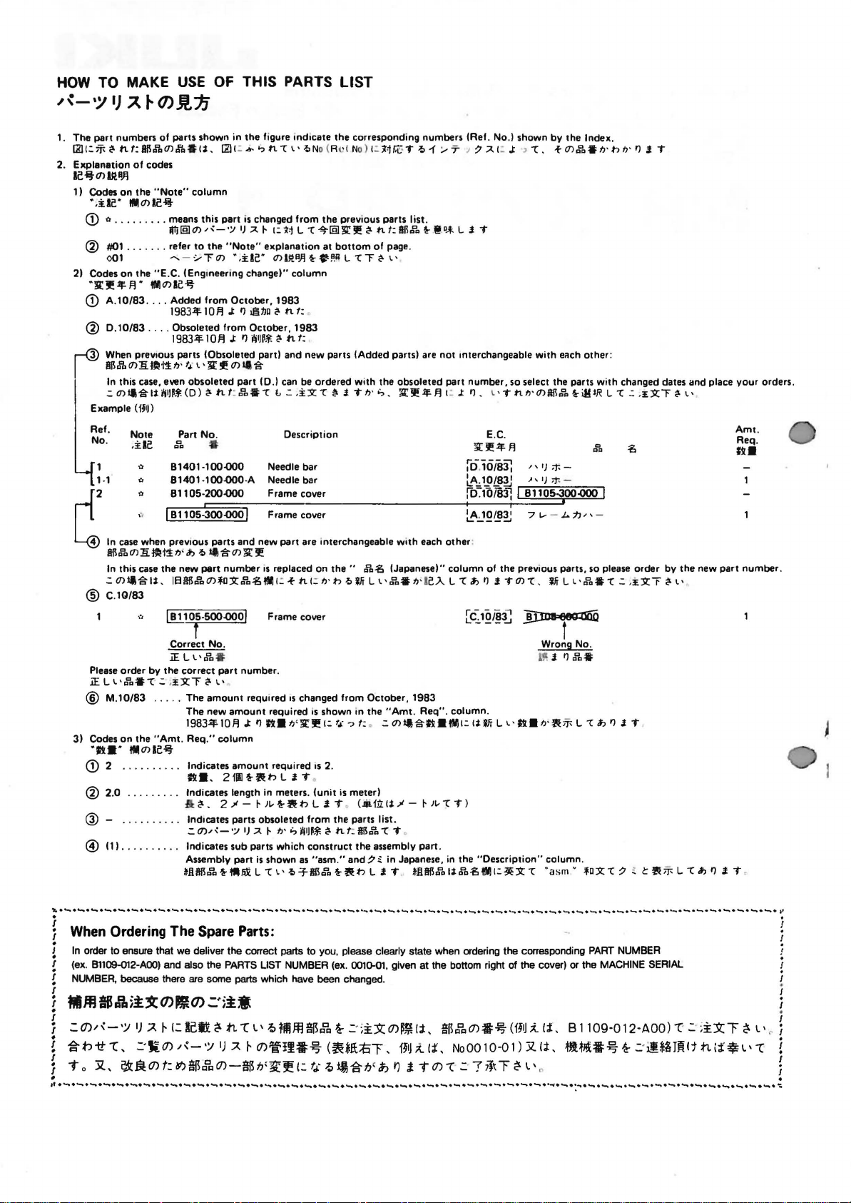
HOW
From the library of: Superior Sewing Machine & Supply LLC
TO MAKE
,~-·~
IJ
A~
USE
(J)JL»jj
OF
THIS PARTS
LIST
1. The part numbers of parts shown in
~t::-r-t!ont:Sll.ra11>.f’a.li,
2. Explanation
ae
-~t m ~
1) Codes
•
(!) o .
@ #01
2) Codes
·11r
(!) A.
@ D.10/83
r—@
I
Ref.
rr42
~
@ C.
Please
.iE L l•.ra•»l.:
@ M.10/83
3) Codes
·ft•·
of
codes
aJl
on
the
«Note»
.ile·
WJm
……..
…
. .
001
on
the «E.C. IEngeneering change)» column
!I!
.lf.
w
10/83
. . . . Added from October, 1983
….
When prev1ous parts (Obsoleted part) and new parts (Added parts) are not Interchangeable with
SB.ra
11>
!i
In
this case, even obsoleted
.:
mll.g.lii’jiJ~t.
EKample
No.
(fJ•Jl
Note
.
ile
»
1·1
0
0
,
.,
In
case when prev1ous parts and new part are interchangeable with each
&B.ra
11>
!i
In
this case
.:
11>!1-g.li,
10/83
order by the correct
on
the
111m1e~
column
le-it
means this part
Jllj[§JI1>,.;:-•;JIJ
..
refer
to
….. -‘/rl1>
W~m
ae
~
1983-lf.IOF!
Obsoleted from October,
1983-lf.
Je!i-:1
fJ•
t~
l •l!r !I!
(D)
Part No.
Q
a a
81401-100.000
81401-100.000-A
81105-200.000
I 811
05-JOO.OQO
tl1″1
fJ
‘ ~
~
the
new
part
J138li.Pa11>lc:SZ:.ra.S!NI
[hl105-SOO.OOOj
f
Correct No.
.iELl•.Pa
.
:~::SZ:T
…..
The
The new
1983-lf.lOF!
«Amt.
Req.» column
(!) 2 . . . . . . . . . . Indicates
ft
••
the
figure end1cate
~t:.b.’:>tl.cl•~N
is
changed from the previous parts list.
;;t. ~ 1::11
the
«Note»
eKplanation at
•,i:Be•
11>I~H}j~.;tP.B
J:
I’J
tli1.JD
t!-
tt
10
F!
J:
I’)
11>
II
part ID.J can be ordered with the obsoleted part number, so select the parts with changed dates and place
~
t1.
t:
.Pa.»l
~~~~*
~
t1.
.g.
L .:
Description
1983
•
Needle
Needle bar
Frame cover
Frame cover
I
II
.g.
11>
~
lJI!
number
IS
replaced on
1:
-t
Frame cover
•
part
number .
~
l’
amount
required
amount
J:
amount
2fll~fl(t:>LI.T
IS
required
I’J
ft.
n’~J!:
required is 2.
@ 2.0 . . . . . . . . . Indicates length in meters. (unit
@ —
…
…
@)
11)
. . . . . . . . . . Indicates
:fl: ~ • 2
.. .. lnd1cates parts obsoleted from
.::(]),,_’;I
Assembly part
*.!ISli.PaHJtAltL»ll·~-Tim.Pa~fl(t:>LI.T
-»
-~ ‘»
IJ
;;t.
sub
parts which
~
~
fJ’.,
is
shown as
ft
the
corresponding numbers (Ref. No.) shown by the lndeK.
o(RPINo)l:~<jr.(::»t~1:..-‘T
L
«(~[§Jl!r!JI!
f:
t:
.i:SZ:
«l
bar
bottom
L
«lr<?-l•
t!o
I.
T
t!-
ttf:8B.Pa
of page.
n·
i:>.
~!!:.iFF!
J
~@.•.t.
L
I.
t:
J:
r.—-~
ID
~A_,
iD-:-foi83J I
I I 4
~;;t.t:J:
T
I’J, l • T
E.
lll:!!:.lf.F!
.10/831
1JlL8;!! » IJ
~J.Q11~
other
:
the»
.ra~
tt
1
.:
n·
t> ~ Wi
changed from October, 1983
IS
shown in
1.:
t~-,
is
t:>
L I. T .
the
~~~~~
~
t1.
construct
«asm.»
(Japanese)» column of
L l •
.Po.
the
«Amt. Req»
f:. .:
11>11-g.ft.!NII:
meterl
(Jit
fti:.li-» — r
parts list .
t:
1m
.Po»(
T .
the
assembly part.
and~~
in Japanese,
trleJ…
L «l ~ I’J
. column.
li
WiLl’
‘»
«l T )
in
~.!ISll.rali.Pa.S!!IIII:~:SZ:»l
the «Description» column.
>
«l.
-tm.Pa•n·t>IJ•I’JI.T
eRch
other:
tt
n·
m&B.ra
~
iHtR L «l .:
C.
«IJ
;f.-
*-
81105-Joo.ooo
71..—J….jJn-
the
previous parts, so please order by
I.
T
11>
«l ,
WiLl· .Pa.»l
..
a a
I
.: ,i:SZ:T ~ l’
~
t
Wrong No.
ll’:
I.
I’J
a»L
•
ft.
n·ft
-r-L «l ~ I’J
·asm»
-tc:SZ:»l~
.
:~::SZ:T
~
I. T
~
cft
~
l’
the
new
-r-
Lc~I’J
part
I. T ,
your
Amt.
Req.
Ill.
number
orders .
.
~·~·~·~·~·~·~·~·~·~·~·~·~·~·~·~·~·~·~·~·~·~·~·~·~·~·~·~·~·~·~·~·~·~·~·~·~·~·~·~·-·~·-·-·-·-·-·-·-·-·~·~·~·~·~’
i
! When Ordering The Spare Parts:
J
In
order to ensure that we deliver the correct parts to you, please clearly
.
I
(ex.
81109-012-AOO)
NUMBER, because
!
I
!
fiiM.Aii:X(1)1f1(1).:.
I
=-
(}).1 ~-·:;
i
.
I
~
h
1t
T 0
«(,
3C
~.61:
.
I
.
I
.
~·~·~·~·~·~·~·~·~·~·~·~·~·~·~·~·
and
also the
PARTS
UST
there are some parts which have been changed.
·
~.t·
1
J A
~
1:
lc~
~
.n
«C
=.·ti
0)
0)
«‘-
t:
~~8′,
1
•:;
A
)
0)-~tJ;~J!
NUMBER
L’
~
nftffl
~Qc,
~
0)1f!l#~
(:
t.~-·
~
·~·~·~·~·~·~·~·~·~·~·~·~·~·-·-·-·-·-·-·-·~·-·~·-·-·-·-·-·-·-·-·-·-·-·-·~·~·~
(~*!:t::tiT,
~!I~
(ex.
~
OOlQ-01
.:·
;
i::>c
1.1
;
.n
state
, given
0)~
i91J
I’)
1.
when ordering
at
the bottom right of
l;t,
gBJ>,
0)#~
~
(;t’,
NoOO
T
0)
«(
.:·?
the
(i91J
10-0 1) :X.I;t,
7l~T
~
corresponding
the
cover) or the
~
li
L
PART
MACHINE
.. B 1109 -0 12-AOO) «(-
~lll#~
NUMBER
SERIAL
!-
.:
·if*3
Jill
It
.:
-;
i::>cT
.tL
(;t ~
~
L’
I
.
!
I
.
L’
I
.
I
«(
.
I
I
.
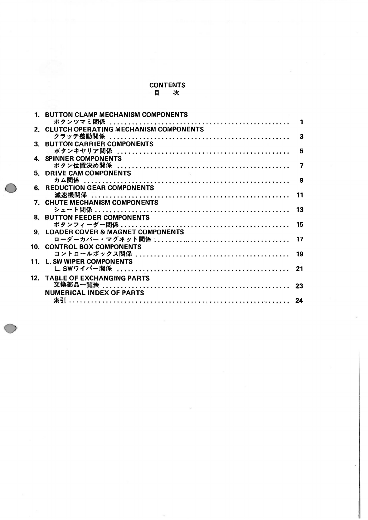
CONTENTS
From the library of: Superior Sewing Machine & Supply LLC
~
.;x
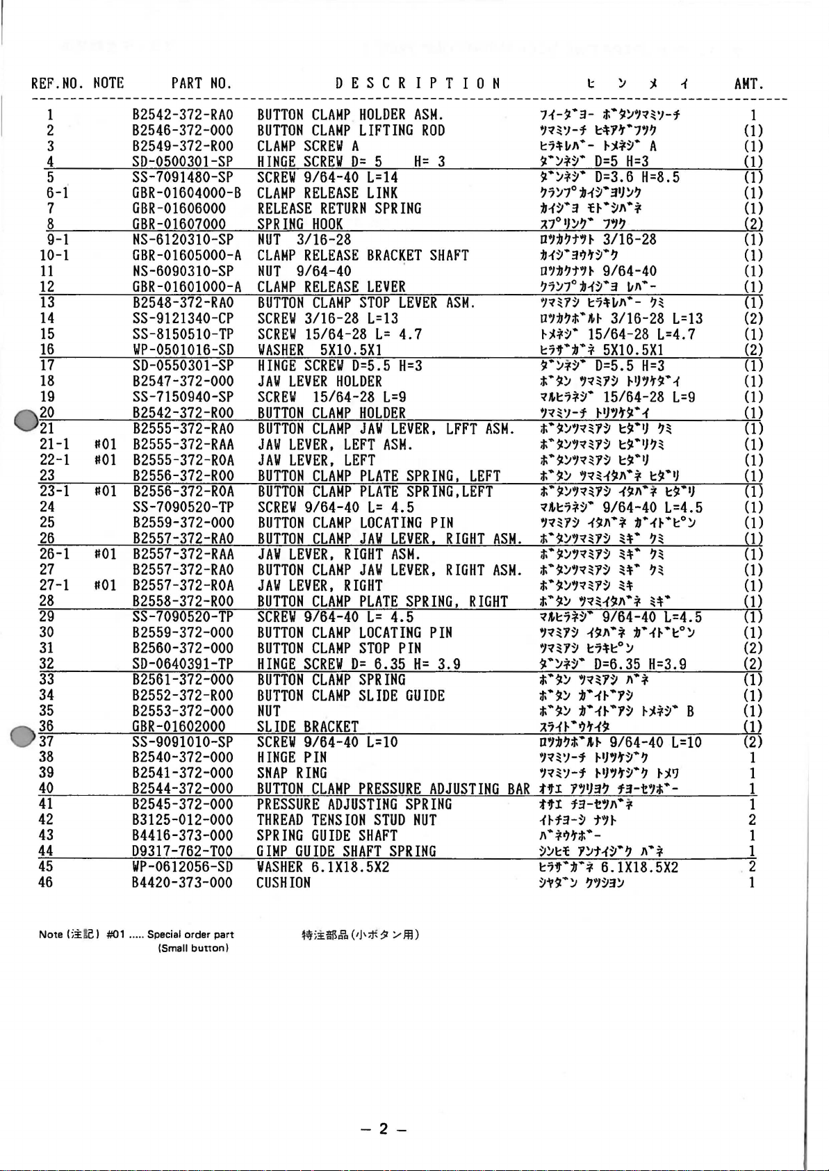
1. BUTTON CLAMP MECHANISM COMPONENTS
* 9
::..-
‘:1-:t
~
001*
. . . . . . . . . . . . . . . . . . . . . . . . . . . . . . . . . . . . . . . . . . . . . . . . . 1
2. CLUTCH
7 7
3. BUTTON CARRIER COMPONENTS
;f.
4. SPINNER COMPONENTS
* 9
5.
DRIVE
1J
REDUCTION GEAR COMPONENTS
6.
ilitll~IVJ1j
7. CHUTE MECHANISM COMPONENTS
~
8. BUTTON FEEDER COMPONENTS
;f-9 ::..-7-(
9. LOADER COVER & MAGNET COMPONENTS
o-‘)1—JJ/’-
10. CONTROL BOX COMPONENTS
::J
11.
L.
SW
L.
12.
TABLE
3CMB6
NUMERICAL
*51
OPERATING MECHANISM COMPONENTS
·:;
71i:lb001j . . . . . . . . . . . . . . . . . . . . . . . . . . . . . . . . . . . . . . . . . . . . . . . . . 3
9
:,.-.:f—7
::..-itr!i~l!f.>001j
CAM COMPONENTS
.L-001*
IJ
71VJ1j
. . . . . . . . . . . . . . . . . . . . . . . . . . . . . . . . . . . . . . . . . . . . . . . 5
. . . . . . . . . . . . . . . . . . . . . . . . . . . . . . . . . . . . . . . . . . . . . . . 7
. . . . . . . . . . . . . . . . . . . . . . . . . . . . . . . . . . . . . . . . . . . . . . . . . . . . . . . . 9
. . . . . . . . . . . . . . . . . . . . . . . . . . . . . . . . . . . . . . . . . . . . . . . . . . . . . .
.:L-
~
!V11~
. . . . . . . . . . . . • . . . . . • • . . . • . . . . • . • . . . . . . • • • . . . • • • . . . . . . • 13
-‘>’-IJil1j……………………………………….
• -:r/f.:t-·:;
::..-
~
c
-JL-;f.
WIPER COMPONENTS
SW?
;f
OF EXCHANGING PARTS
.fb-
·:;
7
.AIVH~
/~-001~
~
. . . . . . . . . . . . . . . . . . . . . . . . . . . . . . . . . . . . . . . . . . . . . . . . . . . 23
INDEX
OF
~IVHj
·
………………………………..
. . . . . . . . . . . . . . . . . . . . . . . . . . . . . . . . . . . . . . . . . . 19
. . . . . . . . . . . . . . . . . . . . . . . . . . . . . . . . . . . . . . . . . . . . . . .
PARTS
……………………………………………..
·
…….
11
15
17
21
24
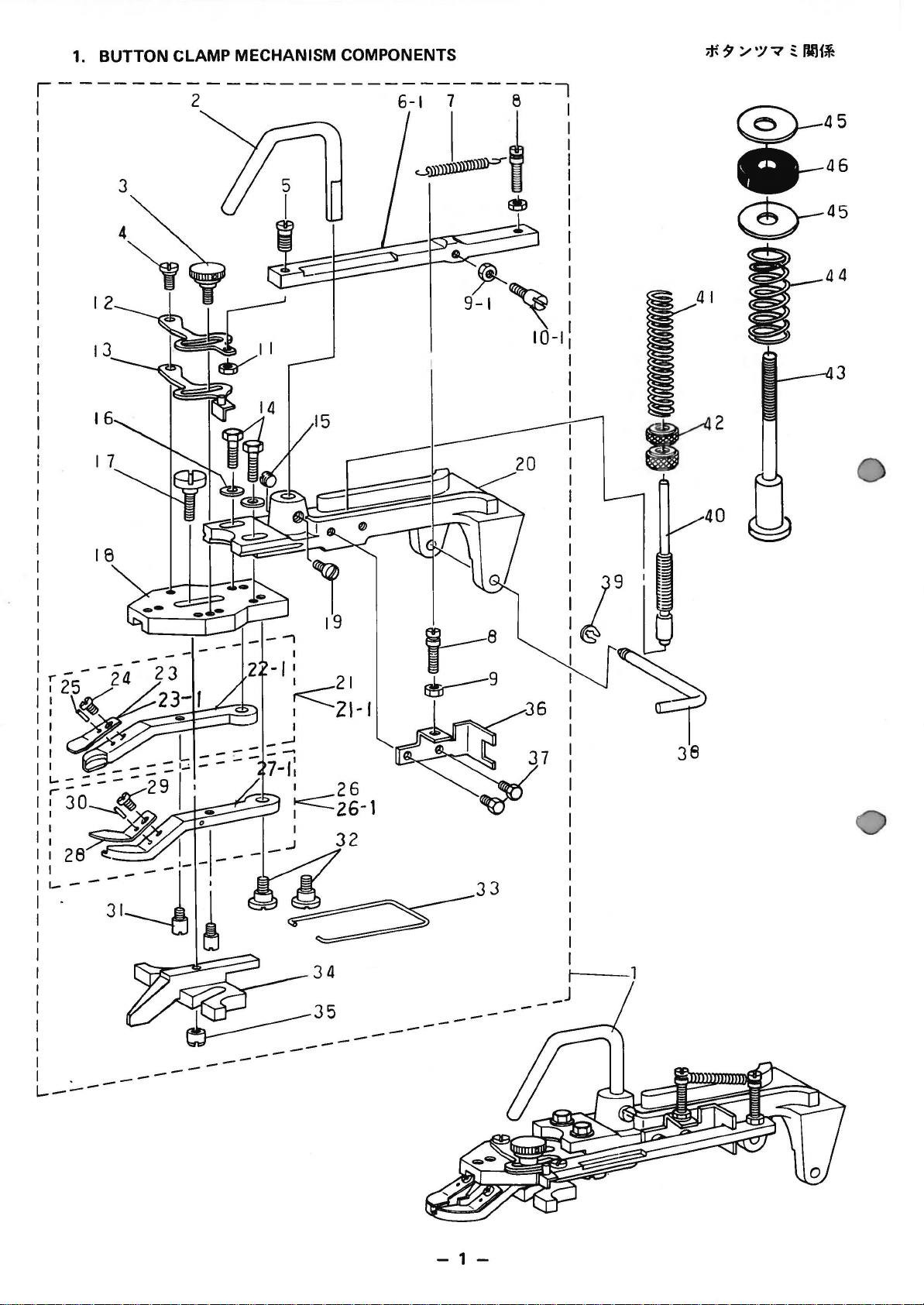
1. BUTTON CLAMP MECHANISM COMPONENTS
From the library of: Superior Sewing Machine & Supply LLC
~—————————-,
1 2
6-1
7 e
@—45
i
1
I
I
I
I
I
I
I
I
I
I
~-
—46
®—-45
2
0
L—:..—
—
—
—
-II
—
I
I
21
:<===z1-1
34
35
—
—
7
__
t—1
J
—
1-
REF.NO.
From the library of: Superior Sewing Machine & Supply LLC
NOTE
PART
NO.
D E S C R I P T I 0 N
AMT.
t
2
3
4
5
6-t
7
8
9-t
tO-t
tt
t2
t3
t4
t5
t6
t7
t8
t9
20
2t
2t-t
22-t
23
23-t
24
25
26
26-t
27
27-t
28
29
30
31
32
33
34
35
36
37
38
39
40
41
42
43
44
45
46
B2542-372-RAO
B2546-372-000
B2549-372-ROO
SD-050030t-SP
SS-709t480-SP
GBR-Ot604000-B
GBR-Ot606000
GBR-Ot607000
NS-6t203t0-SP
GBR-Ot605000-A
NS-60903t0-SP
GBR-Ot601000-A
B2548-372-RAO
SS-9t2t340-CP
SS-8t505t0-TP
WP-050t0t6-SD
SD-055030t-SP
B2547-372-000
SS-7t50940-SP
B2542-372-ROO
B2555-372-RAO
not
B2555-372-RAA
not
B2555-372-ROA
B2556-372-ROO
not
B2556-372-ROA
SS-7090520-TP
B2559-372-000
B2557-372-RAO
not
B2557-372-RAA
B2557-372-RAO
not
B2557-372-ROA
B2558-372-ROO
SS-7090520-TP
B2559-372-000
B2560-372-000
SD-064039t-TP
B2561-372-000
B2552-372-ROO
B2553-372-000
GBR-01602000
SS-9091010-SP
B2540-372-000
B2541-372-000
B2544-372-000
B2545-372-000
B3t25-0t2-000
B4416-373-000
D93t7-762-TOO
WP-06t2056-SD
B4420-373-000
BUTTON
BUTTON
CLAMP
HINGE
SCREW
CLAMP
RELEASE
SPRING
NUT
CLAMP
NUT
CLAMP
BUTTON
SCREW
SCREW
WASHER
HINGE
JAW
SCREW
BUTTON
BUTTON
JAW
JAW
BUTTON
BUTTON
SCREW
BUTTON
BUTTON
JAV
BUTTON
JAW
BUTTON
SCREW
BUTTON
BUTTON
HINGE
BUTTON
BUTTON
CLAMP
CLAMP
SCREW
SCREW
9/64-40
RELEASE
RETURN
HOOK
3/t6-28
RELEASE
9/64-40
RELEASE
CLAMP
3/t6-28
t5/64-28
5X10.5Xt
SCREW
LEVER
t5/64-28
CLAMP
CLAMP
LEVER,
LEVER,
CLAMP
CLAMP
9/64-40
CLAMP
CLAMP
LEVER.
CLAMP
LEVER,
CLAMP
9/64-40
CLAMP
CLAMP
SCREW
CLAMP
CLAMP
NUT
SLIDE
SCREW
HINGE
SNAP
BUTTON
PRESSURE
THREAD
SPRING
GIMP
WASHER
BRACKET
9/64-40
PIN
RING
CLAMP
ADJUSTING
TENSION
GUIDE
GUIDE
6.1X18.5X2
CUSHION
HOLDER
LIFTING
A
D=
5
L=14
LINK
SPRING
BRACKET
LEVER
STOP
L=t3
L=
D=5.5
HOLDER
L=9
HOLDER
JAW
LEVER,
LEFT
ASM.
LEFT
PLATE
PLATE
L=
4.5
LOCATING
JAW
LEVER.
RIGHT
JAW
ASM.
LEVER.
RIGHT
PLATE
L=
4.5
LOCATING
STOP
PIN
D=
6.35
SPRING
SLIDE
L=10
PRESSURE
STUD
SHAFT
SHAFT
SPRING
ASM.
ROD
H=
3
SHAFT
LEVER
ASM.
4.7
H=3
LFFT
ASM.
SPRING,
LEFT
SPRING,LEFT
PIN
RIGHT
RIGHT
SPRING,
RIGHT
PIN
H=
3.9
GUIDE
ADJUSTING
SPRING
NUT
ASM.
ASM.
BAR
7~-~·3-
1~~~-f
t7UJ·-
1·~-1~·
1·~-1~·
~7~7°~~~-3~~~
i~~·3
l7°~~~·
D’~~t’~
~~~·3~~~·~
o’t~t’~
~7~7°~~~·3
1~~1~
o’t~t.·~~
~~-1~·
t7t•t•-1
~·~-1~·
t.·1~
~~t7-1~·
7~~~-f
t-·1~,~~1~
t-·1~,~~1~
t.·~~1~~1~
t-·1~
t-·~~,~~1~
~~t7-1~·
‘~~1~
t-·1~,~~1~
t-·~~,~~1~
t-·~~,~~1~
t.·1~’~U~
t.·1~
~~t?-1~·
‘~~1~
7~~1~
1·~-1~·
t-·1~
t.·1~
t.·1~
l7~~
D7~~t.·~~
7~~~-f
7~~~-f
ttl
ttl
~~f3-~
1·i~~t.·-
~~tt
t7t•:JJ•-1
~11·~ ~7~3~
t.·~~,~~~-f
~1~·1,~
~~-1~·
D=5
D=3.6
t~·~J·-1
7’~
A
H=3
H=8.5
3/16-28
9/64-40
~J·-
t7*~J·-
t5/64-28
~~
3/t6-28
L=4.7
L=t3
5Xt0.5Xt
D=5.5
‘~~1~
~~’~9·~
‘~~~91•-1
~~J·-1
‘~~~11•*
~11
t7*to~
D=6.35
7~~1~
~·~~·1~
~-~~·y~
·~H9
~~,~~·~
~~,~~·~
17~3~
f3-t,J•-1
t’~
1~t~~·;
H=3
~~1~1·~
15/64-28
t9·~
~~
t9·~~~
1
t1
…
J
t9·~
~11·-1
9/64-40
~·~~·to~
~~·
~~
~*·
~~
~*·
~~
H
~~·
9/64-40
…
*
~·~~·to~
H=3.9
J•*
~~-1~·
9/64-40
~~?
f3-t7t.•-
J·-1
L=9
t1·~
L=4.5
L=4.5
L=lO
6.tX18.5X2
B
t
(1)
(1)
(1)
(1)
(1)
(1)
(2)
(1)
(1)
(1)
(1)
(1)
(2)
(1)
(2)
(1)
(1)
(1)
(1)
(1)
(1)
(1)
(1)
(1)
(1)
(1)
(1)
(1)
(1)
(1)
(1)
(1)
(1)
(2)
(2)
(1)
(1)
(1)
(1)
(2)
1
1
1
t
2
t
1
2
t
Note
(;i:!c I #01 ….. Special order
(Small
part
button
I
-2-
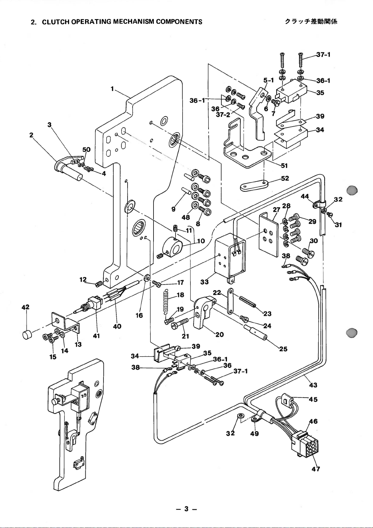
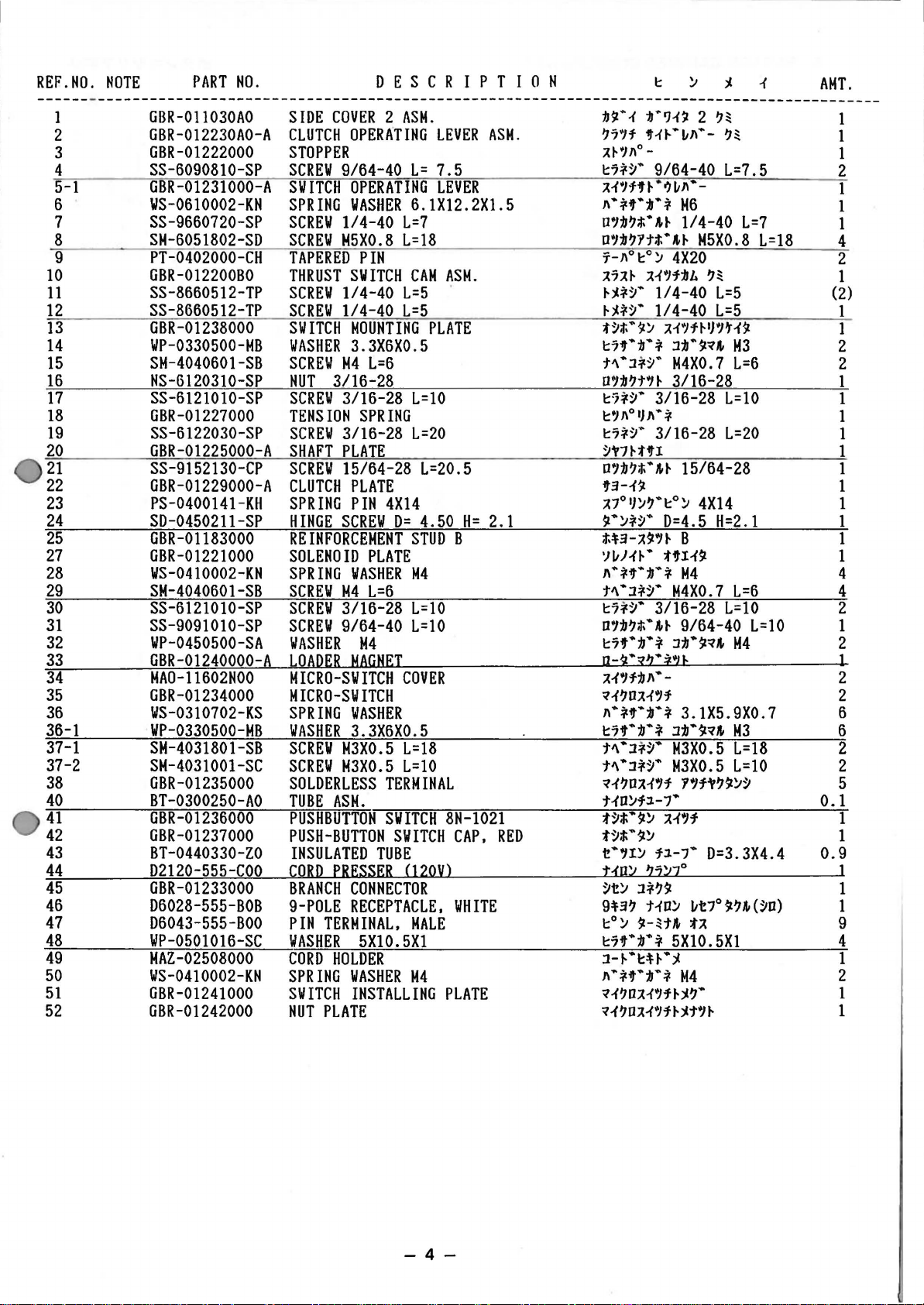
2. CLUTCH OPERATING MECHANISM COMPONENTS
From the library of: Superior Sewing Machine & Supply LLC
-3-
47
REF.HO.
From the library of: Superior Sewing Machine & Supply LLC
1
2
3
4
5-1
6
7
8
9
10
11
12
13
14
15
16
17
18
19
20
21
22
23
24
25
27
28
29
30
31
32
33
34
35
36
36-1
37-1
37-2
38
40
41
42
43
44
45
46
47
48
49
50
51
52
NOTE
PART
GBR-011030AO
GBR-012230AO-A
GBR-01222000
SS-6090810-SP
GBR-01231000-A
WS-0610002-KH
SS-9660720-SP
SM-6051802-SD
PT-0402000-CH
GBR-01220080
SS-8660512-TP
SS-8660512-TP
GBR-01238000
WP-0330500-MB
SM-4040601-SB
NS-6120310-SP
SS-6121010-SP
GBR-01227000
SS-6122030-SP
GBR-01225000-A
SS-9152130-CP
GBR-01229000-A
PS-0400141-KH
SD-0450211-SP
GBR-01183000
GBR-01221000
WS-0410002-KH
SM-4040601-SB
SS-6121010-SP
SS-9091010-SP
WP-0450500-SA
GBR-01240000
MA0-11602HOO
GBR-01234000
WS-0310702-KS
WP-0330500-MB
SM-4031801-SB
SM-4031001-SC
GBR-01235000
BT-0300250-AO
GBR-01236000
GBR-01237000
BT-0440330-ZO
D2120-555-COO
GBR-01233000
D6028-555-BOB
D6043-555-BOO
WP-0501016-SC
MAZ-02508000
WS-0410002-KN
GBR-01241000
GBR-01242000
NO.
D E S C R I P T I 0 N
SIDE
COVER 2 ASH.
CLUTCH
OPERATING
STOPPER
SCREW
SWITCH
SPRING
SCREW
SCREW
TAPERED
THRUST
SCREW
SCREW
SWITCH
WASHER
SCREW
HUT
SCREW
TENSION
SCREW
SHAFT
SCREW
CLUTCH
SPRING
HINGE
9/64-40
OPERATING
WASHER
1/4-40
M5X0.8
PIN
SWITCH
1/4-40
1/4-40
MOUNTING
3.3X6X0.5
M4
L=6
3/16-28
3/16-28
SPRING
3/16-28
PLATE
15/64-28
PLATE
PIN
SCREW
REINFORCEMENT
SOLENOID
SPRING
SCREW
SCREW
SCREW
WASHER
A
LOADER
PLATE
WASHER
M4
L=6
3/16-28
9/64-40
M4
MAGNET
MICRO-SWITCH
MICRO-SWITCH
SPRING
WASHER
SCREW
SCREW
WASHER
3.3X6X0.5
M3X0.5
M3X0.5
SOLDERLESS
TUBE
ASH.
PUSHBUTTON
PUSH-BUTTON
INSULATED
CORD
BRANCH
9-POLE
PIN
TERMINAL,
WASHER
CORD
SPRING
SWITCH
NUT
PLATE
TUBE
PRESSER
CONNECTOR
RECEPTACLE,
5X10.5Xl
HOLDER
WASHER
INSTALLING
LEVER
L=
7.5
LEVER
6.1X12.2X1.5
L=7
L=18
CAM
ASM.
L=5
L=5
PLATE
L=lO
L=20
L=20.5
4X14
D=
4.50
H=
STUD
B
M4
L=10
L=10
COVER
L=18
L=lO
TERMINAL
SWITCH
SWITCH
8N-1021
CAP,
(120V)
WHITE
MALE
M4
PLATE
ASM.
2.1
RED
:b$!
…
1
t•’J1’J.
~71f
iJ’-f~-~~—
;H’:I~o-
~7*~
..
A-i’1f’H·o)~~·-
~·*iJ’•;IJ•i
0′:/:b~t.·~~
0’1:11~Ytt.·,~
1″-~o~o~
A7A~
A-i’1f:bJ.
~~*~·
~~*~·
-~t.·$1~
~7iJ’•t•*
t~·l*~·
U1:11~t»‘J~
~7*~·
~’}OJ}~•*
~7*~·
~»7~tiJ’l
O’:b~;t.·~~
2
~~
~~
9/64-40
L=7.5
M6
1/4-40
L=7
M5X0.8
L=18
4X20
~~
1/4-40
1/4-40
~1’1f~~’1t1$Z
L=5
L=5
l:ll
..
$1~’
M4X0.7
M3
L=6
3/16-28
3/16-28
3/16-28
L=lO
L=20
15/64-28
iJ’3-1$Z
~7°l}~~·~o~
$!·~*~·
t.H-~$!’1~
‘JltN~·
~
…
*,.
..
11
t~·l*~·
~7*~·
D1:11~t.·~~
~7f•11•*
n-~·x2·=1n
~1’1f:b~·
q-{~OA1’1f
~·*,.:b.*
~7iJ’·:b·*
t~·l*~·
t~·l*~·
q-{~D~1’1f
ND~fl.-7•
-~;J;·$!~
t~;r;·$!~
t·,l~
N!]:.t 2j:.t7°
~t~
l*~$!
9~3~
t1D~
~o~
$!-~t~
~7iJ’·:b·*
J-t-·~u·~
~·*iJ'»‘:II
q1~D~1’H~~·
q1~DM$H~~t’~
4X14
D=4.5
H=2.1
B
tiJ’I1$Z
…
*
M4
M4X0.7
3/16-28
9/64-40
l:II•$Zq~
3.1X5.9X0.7
l:b•$Zq~
M3X0.5
M3X0.5
Y’f»~$!~~
~1,1
f:J.-7.
5X10.5X1
.. * H4
L=6
L=lO
L=10
M4
M3
L=18
L=lO
D=3.3X4.4
ltt7°$Z~~(~D)
fA
AHT.
1
1
1
2
1
1
1
4
2
1
(2)
1
1
2
2
1
1
1
1
1
1
1
1
1
1
1
4
4
2
1
2
1
2
2
6
6
2
2
5
0.1
1
1
0.9
1
1
1
9
4
1
2
1
1
—
4-
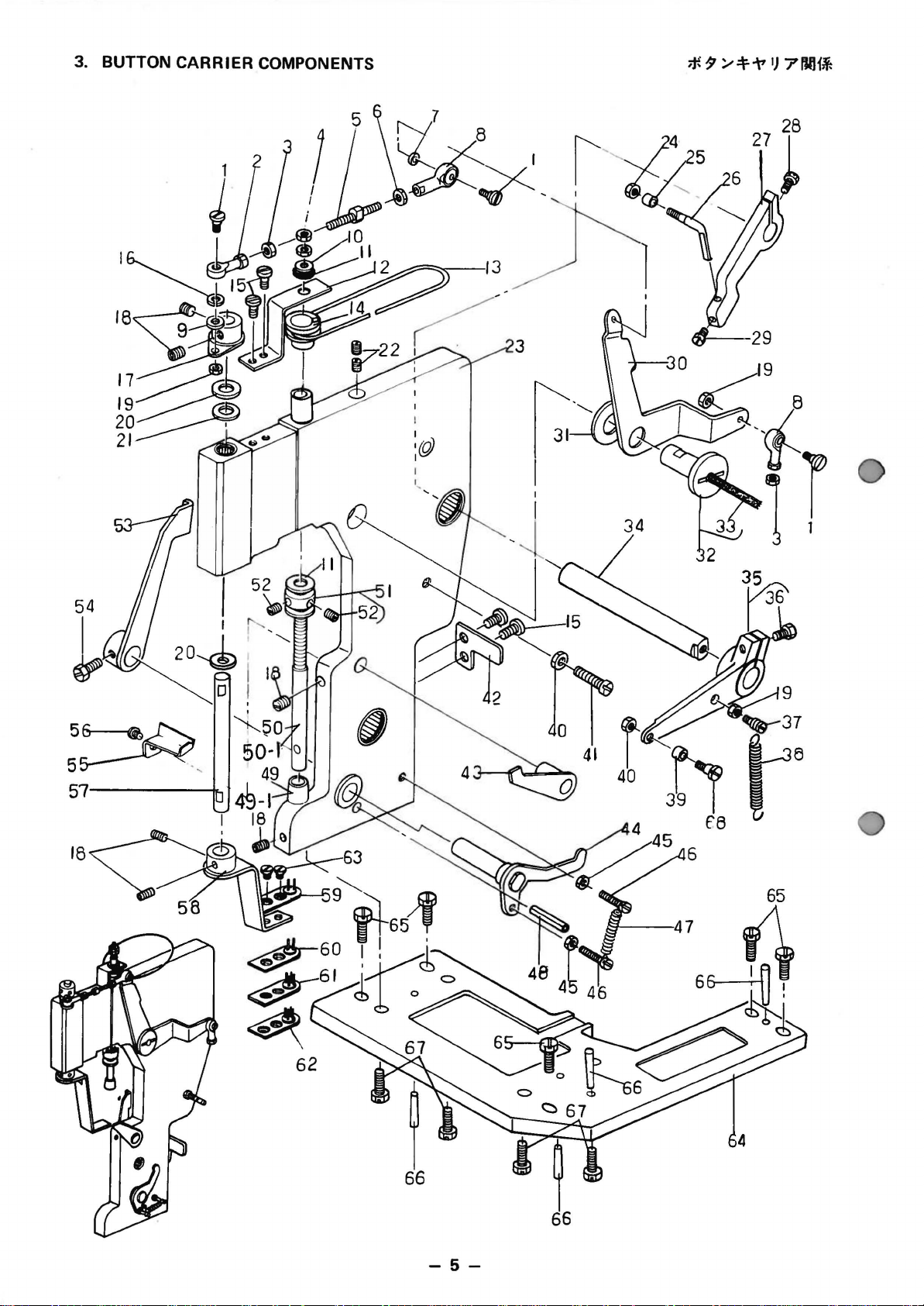
3. BUTTON CARRIER COMPONENTS
From the library of: Superior Sewing Machine & Supply LLC
56-t%~
5~
57——-n.
-5-
REF.NO.
From the library of: Superior Sewing Machine & Supply LLC
I
2
3
4
5
6
7
R
9
10
11
12
13
14
15
16
17
18
19
20
21
22
23
24
25
26
27
28
29
30
31
32
33
34
35
36
37
38
39
40
41
42
43
44
45
46
47
48
49
49-1
50
50-1
51
52
53
54
55
56
57
58
59
60
61
62
63
64
65
66
67
68
NOTE
PART
GBR-01173000
GBR-01170000
GBR-01175000
NH-6060002-SD
GBR-01146000
NM-6040001-SC
WS-0410002-KR
GBR-01171000
IIP-0450000-SD
WP-0612066-SP
B1116-804-000
GBR-01177000-A
R0-6465701-00
GBR-011440AO
SS-9120910-TP
WS-0410002-KR
GBR-011470AO
SS-8660512-TP
NS-6090310-SP
B2557-280-00B
GBR-01169000
SS-8660810-TP
GBR-011020AO
GBR-01161000
GBR-01160000
GBR-01159000
GBR-01158000
SS-9152130-CP
SS
-9151630-CP
GBR-01141000
GBR-01140000
GBR-011390AO
CQ-3030000-00
GBR-01164000
GBR-011380AO
SS-9152130-CP
GBR-01357000
GBR
-01184000
G
BR
-01172000
NS-6110310-SP
SS-7112420-SP
GBR-01119000-A
GBR-011350AO
GBR-011300AO
NS-6080210-SP
SS-6081810-SP
GBR-01129000
PS-0400151-KH
GBR-01149000
«02
GBR-01149AOO
GBR-01143000
«02
GBR-01143AOO
GBR-011480AO
SS-8620610-SP
GBR-011330AO-A
SS-9660720-SP
GBR-01176000
SS-9080410-SP
GBR-01162000
GBR-011500AO-A
«01
GBR-01152AAO
«01
GBR-01152BAO
«01
GBR-01152CAO
«01
GBR-01152DAO
SS-2090510-SP
GBR-01101000
SS-9152130-CP
PT-0402000-CH
SM-6061502-SD
GBR-01137000
NO.
SCREW
ROD
ROD
NUT
CONNECTING
NUT
SPRING
ROD
WASHER
WASIIER
CLOTII
THRUST
RUBBER
PULLEY
SCREW
SPRING
SPINNER
SCREW
NUT
WASHER
SEAL
SCREW
SIDE
NIJT
ROLLER
WORK
UPPER & LOWER
SCREW
SCREW
OSCILLATING
SPACER
SPINNER
OIL
LINK
HOLDING
SCREW
SPRING
TENSION
ROLLER
NUT
SCREW
STOPPER
STOPPER
CLAMP
NUT
SCREW
TENSION
SPRING
WORK
WORK
ROTATING
ROTATING
LEAF
SCREW
CLAMP
SCREW
COVER
SCREW
ARM
SPINNER
BUTTON
BUTTON
BUTTON
BUTTON
SCREW
BASE
SCREW
TAPERED
SCREW
CAM
D E S C R I P T I 0 N
END
1
END
NUT,
LEFT
H6
ROD
H4
WASHER,
END
2
H4
4.5X8X0.5
6.1XllX2
PLATE
WASHER
SUPPORT
PLATE
RING
ASH.,
3/16-28
SHALL
L=9
WASHER.
M4
OSCILLATING
1/4-40
L=5
9/64-40
FOR
NEEDLE
1/4-40
BEARING
L=8
COVER 1 ASH.
CLAMP
FOOT
LIFTING HOOK
ARM
15/64-28
15/64-28
L=20.5
L=15.5
LEVER
SUPPORT
ARM
WICK
SUPPORT
15/64-28
SHAFT
CLAMP
DRIVE
L=20.5
HOOK
SPRING
STUD
BRACKET
11/64-40
11/64-40
L=24
PLATE
ASH
.
RELEASE
ARM
ASH.
1/8-44
1/8-44
L=18.0
SPRING
PIN
CLAMP
ATTACHMENT
CLAMP
ATTACHMENT
ROD
ROD
SPRING
BRACKET
3/16-32
RELEASE
1/4-40
1/8-44
ARM
L=7
L=4.3
L=6
ASH.
SHAFT
OSCILLATING
CARRIER
CARRIER
CARRIER
CARRIER
9/64-40
ASH.
ASH.
ASH.
ASH
L=5
.
CASTING
15/64-28
L=20.5
PIN
M6
L=15
ROLLER
SHAFT
ARM
PIN
ARM
A
ASH.
B
ARM
LEVER
ASH.
ASH.
ASM.
n•H
·1~~ • pJ•H*~·
D~~·l~~·
D7~·l~~·-t~~
D~:IJ?t~~
~~~~·Jn•H
D7:1J?t7~
11·*11·:1J·*
D7~·l~~·
~7f·:IJ·*
~711·:1J·*
«J.Jt•-t
~7::H~~1t
01}~?·
1°-1)
D7:1J?t.·~~
11·*-,·:IJ·*
t~:IJ1
ASM.
~~*~
o•J:IJ?t~
3:J:f?IJ~T·
=-~·~~-1~~?·3-
~~*~
1Jt•-t
M6
•
M4X0.7
M4
4.5X8X0.5
6.1X11X2
,.
(~3-)
3/16-28
M4
1-J.J,J
..
1/4-40
~
9/64-40
,.:IJ
..
1/4-40
:IJ•’J-tt
2~:t
?~
..
—
..
1
D-7
:;tJ:tHr~·
;,tJHl
D7:1J?t.·~~
D7:1J?t.·~~
~3-~:1-1-J.
~~0-·-
t~:IJ-{1-J.
:1~~
«J.1Hl1J~?
«J.J:tn
D~:IJ?t.·~~
~70
t·1·u~.
J1)~·3-
D~:b?t•J~
~~~7*~·
:IJJ.
~~711°-
?7~7°
u•J:IJ?t·J~
~7*~·
~~11ol}11•*
~7o1J~?·~o~
‘1-?
‘1-?1t~f~~~
:IJ17~D~~·
:IJ17~D7~
1tJI
~~*~·
?7~7°:1J1~·37-J.
D~:IJ?t.·~~
;t.•t~:tf t.•-~:IJII•-
D7:1J?;J;
1-J.~·?
t~:b11-J.
;~;·t~~’1
;t;•t~H1JY B ?~
;t;·t~~’1
t.·t~~’1
~~f7*~·
:llt•-t
D7:11?;t.·~~
7-11°
D~:IJ?1t;t;·,~
D-7
7~?
~·3-~·1-1.
15/64-28
15/64-28
t~:IJ-{1!11·-
~~·t·~,~~o~ ?~
~~·~·?
?~·-1-1.
15/64-28
1)~?·7~?
u·~11·*
:ID~·?’)~
11/64-40
11/64-40
~~711°—ft
?~
:IJ1~·31-J.
118-44
1/8-44
1t·Jt~~~
..
*’)~
?~
3/16-32
1/4-40
..
~~
1/8-44
?~
1
11 A ?~
1
JY c ?~
1
JY D ?~
9/64-40
~t~·-~
15/64-28
~o
~
4X20
M6
~I)•J~~·?
~t·~
1~:1
L=9
?~
L=5
* B
~-~
L=8
?~
?~
L=24
A
?
L=l8
L=6
B
?~
L=7
L=4.3
L=5
L=15
~
AMT.
3
1
2
2
1
1
1
2
1
1
2
1
1
1
4
2
1
6
3
2
1
2
1
1
1
1
1
1
1
1
1
1
(0.
1)
1
1
(1)
1
1
1
2
1
1
1
1
2
2
1
1
1
1
1
1
1
(2)
1
2
1
1
1
1
1
1
1
1
2
1
5
4
4
1
Note ()i:
ft
e)
#01 ….. Selecting
#02
….. Special
(Small
part
order
button)
part
iJltRM.ff,
~ii.M.ff,(‘l’*:il
;..-If!)
-6-
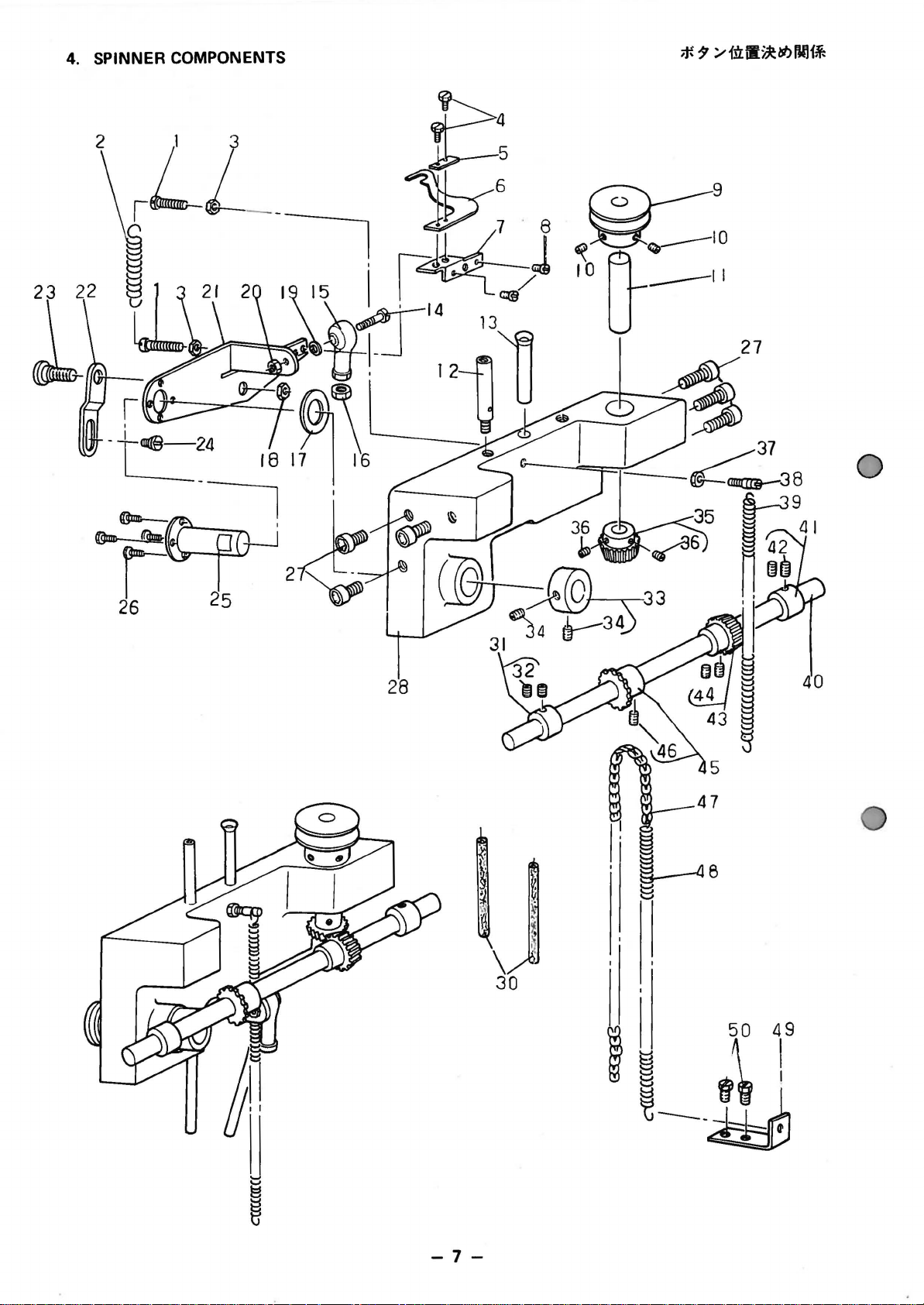
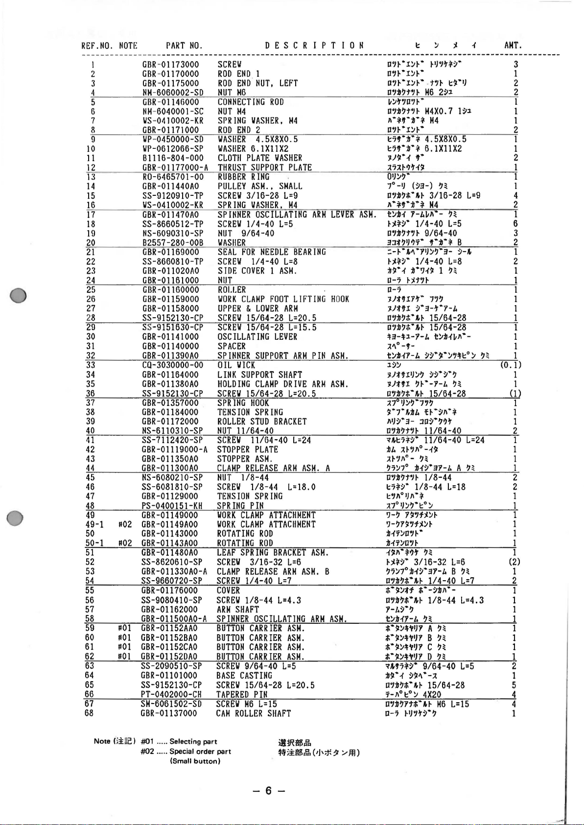
4.
From the library of: Superior Sewing Machine & Supply LLC
SPINNER
2
—
COMPONENTS
to@
-24
-~
I B
17 16
I p 0 /
27
0
I
26
-7-
-
9, −9 − 1) The knife moves in accordance with the lifting of the button clamp. Therefore, the length of the remaining thread on the wrong side of a fabric depends upon the height of the button clamp at which the thread is trimmed. (In case of MB-373/ 377) For MB-372, the lifting amount of the button clamp is higher as the button clamp cuts by its lifting force the thread l…
-
33, iii R SINGLE THREAD, CHAINSTITCH BUTTON ATTACHING MACHINE WITH AUTOMATIC THREAD TRIMMER MB-373 MB-377 ENGINEER’S MANUAL 29231701 No.01 (WITH KNOT-TYING MECHANISM)
… -
23, −23 − ™ Loosen two screws 1 and adjust so that the roller of the knot-tying arm comes in contact with the knot-tying notch when the needle bar goes up at the fourteenth stitch as high as 30 to 35 mm above the needle bar upper bushing. ™ If two knot-tying notches are to be installed (without cross- over stitch), make the aforementioned adjustment at the 6th and 14th stitches. ™ …
-
5, −5 − ™ For adjusting the timing of the travel of the yoke slide, align the engraved marks of the loop positioning finger cam and the triangle loop positioning finger cam with the engraved mark of the cam and looper sleeve after the adjustment of the looper so that the engraved marks are on a straight line. Then temporarily tighten the screws. 1) Adjust t…
-
1, 1. SPECIFICATIONS MB-373 MB-377 Other specifications are same as those of MB-373. −1 −−1 − 1 2 3 4 5 6 7 8 9 10 11 Sewing speed Number of stitches Amount of feed Stitching pattern Button size Needle bar stroke Needle Automatic thread trimmer Presser lifter Stop-motion unit Power supply Max. 1,500 rpm Normal speed 1,300 rpm 8, 16, and 32 stitches (6, 12 and 24 stitches are al…
-
11, −11 − ™ Remove the machine arm side cover (left), loosen the screw of nipper bar block 3 and move nipper bar block 4 to the right or left to perform adjustment. ™ Loosen the stitch adjusting cam screw A, and turn the cam in the rotational direction to make adjustment. ™ If the impact at the time of the stop motion is too great, increase the clearance, and if the cam stops be…
-
21, −21 − ™ Loosen screw 1 and adjust so that the clearance between the outside periphery of the roller of the knot-tying arm and that of the stitch adjusting cam should be 1 to 1.5 mm at the time of stop-motion. ™ If the clearance is too large, the stroke of the thread bind plate will become short. ™ If the clearance is too small, the roller may come in contact with t…
-
3, −3 − ™ Turn the hand wheel by hand and loosen screw 1 in the Fig. A in the thread take- up lever to adjust so that the upper engraved line of the two engraved lines on the needle bar aligns with the bottom of lower bushing 3 when the needle bar is at its lowest position. For the old type sewing machine, in addition, adjust the position so that needle clamp screw 4 enters …
-
16, −16 − (1) The mechanism and the name of each component of the thread trimmer As shown in the figure below, when the button clamp lifting lever is actuated at the final stitch, the thread trimming connecting link (rear) moves forward, causing the thread separating claw of the moving knife to separate thread before it is trimmed by the knife. Unlike MB-372, the stop-motion timing is del…
-
13, −13 − 1) Perform adjustment to provide the 2.4 mm clearance after loosening screw 1 of the stop motion tripping lever. Remove the stop motion disc pressure lever and the needle driving pulley, insert a 2.4 mm gauge or a 3 mm wrench between the stop motion plunger and the stop motion disc, and tighten srew 1 of the stop motion tripping lever since the stop motion lever s…
-
14, −14 − (13) Positioning the needle driving pulley pressure applying lever The clearance at the stop-motion position (while the driving pulley is running idle) should be 0.2 to 0.3 mm. (14) Positioning the thread pull-off lever Adjust the position of thread pull-off lever 1 so that the dimension between thread guide pole 4 and thread pull-off lever 1 is 5 to 9 m…
-
26, − 26 − 5. CORRECTIVE MEASURES FOR STITCHING TROUBLES (1) Thread breakage 1) The looper hooks thread twice due to improper lengthwise positioning of the yoke slide. ™ Move the loop positioning finger cam back and forth to make readjustment so that the blade point of the looper passes through the center of the thread triangle at the 9th or 10th stitch. 2) …
-
12, −12 − (10) Positioning the stop motion disc and the stop motion plunger 1) The clearance between the stop motion disc and the stop motion plunger should be 2.4 mm while the machine is in operation or at the position of 3 to 4 stitches from the position of stop-motion. 2) The clearance between the stop motion plunger lever and the stop motion plunger should be 8…
-
7, −7 − ™ Align the engraved point on the cam with the pivot on the bed at the position of stop motion. Then, tighten the setscrew of cam. After the adjustment, turn the stop motion pulley by hand and confirm that the button clamp stops at the distance of about 13 mm between the top of needle and the top surface of throat plate when the needle bar descends by means of crosswise …
-
25, −25 − ™ Make adjustment by loosening screw 1 of the tension lever. At the time of starting, make adjustment by loosening screw 2 of the tension guide. ™ If the clearance is too large, the start of the brake will be delayed and the stop motion cam may bound or produce a loud noise at the time of stop-motion. ™ If the clearance is too small, the b…
-
34, iv Please do not hesitate to contact our distributors or agents in your area for further information when necessary. * The description covered in this engineer’s manual is subject to change for improvement of the commodity without notice. 00 · 11 Printed in Japan (E) R INTERNATIONAL SALES DIVISION 8-2-1. KOKURYO-CHO. CHOFU-SHI. TOKYO 182-8655. JAPAN PHONE : (81)3-3430-4001 …