-
Contents
-
Table of Contents
-
Troubleshooting
-
Bookmarks
Quick Links
User Manual
Puritan Bennett
TM
560 Ventilator
Related Manuals for Covidien Puritan Bennett 560
Summary of Contents for Covidien Puritan Bennett 560
-
Page 1
User Manual Puritan Bennett 560 Ventilator… -
Page 2
Nothing in this manual shall limit or restrict in any way Covidien’s right to revise or otherwise change or modify the equipment (including its software) described herein, without notice. In the absence of… -
Page 3: Table Of Contents
Table of Contents Preface Purpose of This Manual …………xi Qualification of Personnel .
-
Page 4
Table of Contents 2.11 USB Memory Device Menu ……….2-11 2.12 If Ventilator Failure Occurs . -
Page 5
Table of Contents Operating Procedures Turning on the Ventilator ……….. 5-1 USB Menu Parameters . -
Page 6
Table of Contents Indicators and Alarms …………A-2 Performance . -
Page 7
List of Figures Figure 1-1. Locations of Labels—Top-Front View ……….. . 1-25 Figure 1-2. … -
Page 8
List of Figures Figure 4-24. Mounting the Ventilator on the Utility Cart……….4-29 Figure 4-25. … -
Page 9
List of Tables Table 1-1. Ventilator Symbols …………..1-19 Table 1-2. … -
Page 10
Page Left Intentionally Blank… -
Page 11: Purpose Of This Manual
Information regarding your product warranty is available from your sales representative or Covidien. Extended Service The Puritan Bennett™ 560 ventilator offers extended service contracts/warranties for purchase when the ventilator is purchased. Please contact your local Covidien sales or service representative for addi- tional information.
-
Page 12: Service Centers
Here, you will find answers to frequently asked questions about the product and other Covidien products 24 hours a day, 7 days a week. If you require further assistance, contact your local Covidien representative.
-
Page 13
Service Centers Covidien France SAS Covidien Hong Kong Covidien ECE s.r.o. Covidien India C-Mill Gebouw K Unit 12 — 16, 18/F Magyarországi Fióktelepe 10th Floor Building No 9B Jan Campertstraat 21-A BEA Tower Mariássy u.7. DLF Cyber City Phase III Gurgaon… -
Page 14
Preface Covidien Spain S.L. Covidien Sverige AB Covidien Switzerland Covidien Thailand C-Mill Gebouw K C-Mill Gebouw K C-Mill Gebouw K 99 Soi Rubia Jan Campertstraat 21-A Jan Campertstraat 21-A Jan Campertstraat 21-A Sukhumvit 42 Road 6416 SG Heerlen, Netherlands 6416 SG Heerlen, Netherlands 6416 SG Heerlen, Netherlands 13-14 Fl., Berli Jucker Building… -
Page 15: Safety Information
1 Safety Information Definitions This manual uses three indicators to highlight critical information: warning, caution, and note. They are defined as follows: WARNING Indicates a condition that can endanger the patient or the ventilator operator. Caution Indicates a condition that can damage the equipment. Note Indicates points of particular emphasis, that make operation of the ventilator more efficient or con- venient.
-
Page 16
Safety Information WARNING: The ventilator must be used according to its intended use. Refer to section 2.1, Indications for Use. WARNING: Be aware this manual describes how to respond to the ventilator, but does not tell you how to respond to the patient. -
Page 17
If the ventilator fails the alarm tests or if you cannot complete the tests, refer to Chapter 3, Alarms and Troubleshooting or call your equipment supplier or Covidien. WARNING: When an alarm condition is triggered, or there is evidence of a patient-ventilator fault or problem, examine the patient first before examining the ventilator. -
Page 18: Warnings Regarding Installation And Environment Of Use
Safety Information WARNING: Do not connect the ventilator to any device other than a PC with a dedicated compatible Puritan Bennett™ software package. WARNING: The ventilator system is not intended to be a comprehensive monitoring device and does not activate alarms for all types of conditions.
-
Page 19
Warnings WARNING: To avoid damage to the ventilator, in particular the batteries or electrical components, fluids must not be allowed to enter the device, particularly through the air inlet filter or the cooling apertures located in the side, rear, and bottom panels of the ventilator. WARNING: To ensure correct and lasting operation of the device, ensure that the ventilator is installed and operated in the environmental conditions recommended in Appendix A, Specifications. -
Page 20
60°C (140°F). This may lead to undesirable side effects for the patient. To avoid injury to the patient move the patient and the ventilator to a cooler location. For more information, contact Covidien. WARNING: The default setting for altitude compensation is YES. Altitude compensation should always be set to YES for accurate volume delivery calculations at all elevations. -
Page 21: Warnings Regarding Electrical Power Supplies
Warnings WARNING: Exercise care to avoid any potential significant risks of reciprocal interference posed by the ventilator and accessories during specific investigations or treatments. Warnings Regarding Electrical Power Supplies 1.2.3 WARNING: The operator should connect the ventilator to an AC power source whenever available, for safer operation.
-
Page 22: Warnings Regarding Hoses And Accessories
Safety Information WARNING: Even if the internal battery charging indicator is off, charging of the battery may sometimes be incomplete if the ambient temperature is above 40°C (104°F) because of the battery’s internal heat safety device. WARNING: When the Low Battery alarm is triggered, immediately connect the ventilator to an AC power supply to maintain ventilation and recharge the internal battery.
-
Page 23
Warnings WARNING: The exhalation block is intended for single use by a single patient . It may periodically be cleaned, but it cannot be disinfected or sterilized. To maintain good measurement quality when used continuously, clean the exhalation block periodically (refer to section 7.3, Cleaning the Exhalation Block). -
Page 24
(Max VTI), and minimum inspired volume (Min VTI) settings—must be periodically adjusted according to changes in the patient circuit resistance—especially when filters are replaced. WARNING: To ensure proper performance of the ventilator, use a patient circuit recommended by Covidien in this manual; refer to Chapter 4, Installation and Assembly… -
Page 25: Warnings Regarding Settings
Ø 22 mm for adult patients, and a corrugated tube of Ø 15 mm for pediatric patients with a tidal volume lower than 200 ml. WARNING: To ensure proper performance of the ventilator, use only accessories (including oxygen accessories) approved and recommended by Covidien. See Appendix F, Parts and Accessories or contact your customer services.
-
Page 26
Safety Information WARNING: Ensure that the I Sens setting is not set to OFF when ventilating patients capable of triggering spontaneous breaths. WARNING: The ventilator offers a variety of breath delivery options. Throughout the patient’s treatment, the clinician should carefully select the ventilation mode and settings to use for that patient, based on clinical judgment, the condition and needs of the patient, and the benefits, limitations, and characteristics of the breath delivery options. -
Page 27
Warnings WARNING: The Apnea alarm should be set to YES for ventilator dependent patients. WARNING: Setting any alarm limits to OFF or extreme high or low values can cause the associated alarm not to activate during ventilation, which reduces its efficacy for monitoring the patient and alerting the clinician to situations that may require intervention. -
Page 28: Warnings Regarding Pc Connection And Usb Memory Devices
WARNING: To ensure proper servicing and avoid the possibility of physical injury to personnel or damage to the ventilator, only personnel authorized and qualified by Covidien should attempt to service or make authorized modifications to the Puritan Bennett™ 560 ventilator.
-
Page 29
Do not attempt to open, repair or otherwise service the ventilator yourself. Doing so might endanger the patient, damage the ventilator, or void your warranty. Only personnel authorized and qualified by Covidien should repair, open or service the ventilator. WARNING:… -
Page 30
Safety Information WARNING: A patient treated by mechanical ventilation is highly vulnerable to the risks of infection. Dirty or contaminated equipment is a potential source of infection. Clean the ventilator and its accessories regularly and systematically before and after each use and following any maintenance procedure to reduce the risks of infection. -
Page 31: Warnings Regarding Oxygen
Warnings WARNING: Connect the external electrical power source by first connecting the power cable to the ventilator and then to the external power source. Follow the reverse procedure to disconnect the device from electrical power sources. Warnings Regarding Oxygen 1.2.8 WARNING: The ventilator must not be used with flammable anesthetic substances.
-
Page 32
Safety Information WARNING: The hose connecting the ventilator to the oxygen source must be designed exclusively for use with medical-grade oxygen. Under no circumstances should the oxygen hose be modified by the user. In addition, the hose must be installed without the use of lubricants. WARNING: Ensure that the only gas supplied to the ventilator through the dedicated oxygen supply connector is medical-grade oxygen. -
Page 33: Warnings Regarding Electromagnetic Interference
The use of any accessory other than those specified, with the exception of the power supplies or cables sold by Covidien, may lead to an increase in electromagnetic emissions or a decrease in the equipment protection against electromagnetic emissions. If the ventilator is used adjacent to such accessories or stacked with such devices, the ventilator’s performance should be monitored to verify normal…
-
Page 34
Safety Information Table 1-1. Ventilator Symbols (Continued) Symbols Descriptions Insulation class II equipment (IEC 60417-5172). A regulatory standard classification for protection against electric shock. Class II equipment relies on double insulation rather than protective earthing. This symbol appears on the ventilator’s back panel; see item 5 in Table 1-2. … -
Page 35
Symbols and Markings Table 1-1. Ventilator Symbols (Continued) Symbols Descriptions Exhalation valve pilot port. This symbol appears on the front right of the ventilator, adjacent to the exhalation valve and TO PATIENT ports, indicating the connection of the tubing between the patient circuit exhalation valve; see Figure 1-1, and item 3 in Figure 1-4. … -
Page 36
Safety Information Table 1-1. Ventilator Symbols (Continued) Symbols Descriptions Inspiratory effort detected. This symbol appears in the front panel display’s Status window when the patient triggers a breath. Parameter adjustment bar. This graphic shows the current setting for parameters such as display contrast and alarm volume in the Pref- erences menu. -
Page 37
Table 1-1. Ventilator Symbols (Continued) Symbols Descriptions PC connection. This symbol indicates a port that can be used by authorized Covidien product service personnel or Covidien service personnel for software maintenance. See item 10 in Figure 1-3. Atmospheric pressure limitations. See section for specifications. -
Page 38: Labels (Identification And Instruction Information)
Safety Information Labels (Identification and Instruction Information) Various labels or specific markings are affixed to the ventilator that describe precautions to be taken for the correct use of the ventilator and contribute to the traceability of the product. See Table and the figures on the following pages for illustrations of these labels and markings and their loca- tions on the ventilator.
-
Page 39: Figure 1-1. Locations Of Labels-Top-Front View
Labels (Identification and Instruction Information) Note: The item number callouts in the following figures correspond to those listed in Table 1-2. Figure 1-1. Locations of Labels—Top-Front View Figure 1-2. Locations of Labels—Front-Left View User Manual 1-25…
-
Page 40: Figure 1-3. Location Of Labels And Markings-Rear View
Safety Information Figure 1-3. Location of Labels and Markings—Rear View Figure 1-4. Location of Labels—Bottom View 1-26 User Manual…
-
Page 41: Ventilator Overview
2 Ventilator Overview Indications for Use The Puritan Bennett™ 560 Ventilator is indicated for the continuous or intermittent mechanical ventilatory support of patients weighing at least 11 lb (5 kg) who require mechanical ventilation. The ventilator is a restricted medical device intended for use by qualified, trained personnel under the direction of a doctor.
-
Page 42: Target Operators
Ventilator Overview Association), International Maritime Dangerous Goods code for sea and the European Agreement concerning the International Carriage of Dangerous Goods by Road (ADR) for Europe. Private individuals who transport the device are excluded from these regulations although for air transport some requirements apply.
-
Page 43: Operational Use
Operational Use Operational Use The Puritan Bennett™ 560 ventilator uses a micro-turbine to provide ventilatory support to patients. Clinicians may use a variety of interfaces to connect patients to the ventilator for continuous or intermittent ventilatory support. Some examples include mouthpieces; nasal masks or full face masks;…
-
Page 44: Device Classification
Ventilator Overview WARNING: Users must always possess an additional breathing circuit and exhalation valve while using the Puritan Bennett™ 560 ventilator. Device Classification The ventilator’s IEC/EN 60601-1classification is as follows: Protection/insulation class (electric shock): Class II • Protection index of enclosure: IP32 •…
-
Page 45: Front Panel
Front Panel Front Panel Figure 2-1. Front Panel LCD display—Shows information about the ventilator, including Exhalation valve port—Nipple for providing piloting patient hours and software version, ventilation modes and settings, pressure to the exhalation valve. Controls the open-closed and monitored and calculated patient data and waveforms. The position of the exhalation valve.
-
Page 46: Back Panel
Ventilator Overview Back Panel Figure 2-2. Back Panel Ergonomic carrying handle. PC cable connector: USB mini-B connector used for Puritan Bennett™ ventilator test software. WARNING: Do not connect the ventilator to any device other than a PC with a dedicated compatible Puritan Bennett™ soft- ware package.
-
Page 47: Control Panel
Control Panel Control Panel Figure 2-3. Control Panel Alarm indicators (two LEDs): DOWN/FREEZE key: Red indicator: • Moves the cursor down and decreases parameter values. • Continuous: Very high priority (VHP) alarm activated. • During ventilation, freezes the waveform shown in the Wave- form menu.
-
Page 48: Ventilation Menu
Ventilator Overview Ventilation Menu Figure 2-4. Ventilation Menu Display (on standby at left; during ventilation at right) 1 General information line: 2 Ventilation settings: 3 Preferences menu access line: Shows the current ventilation mode, Shows the specific ventilation parameter Highlight this line and press the along with the following: values for the currently selected ventilation ENTER…
-
Page 49: Alarm Menu
Alarm Menu Alarm Menu Figure 2-5. Alarm Menu (on standby at left; during ventilation at right) 1 Title line: 2 Alarm settings: 3 Access line to Alarm Logs menu. Shows ventilation mode and the follow- Shows the specific alarm parameter Highlight this line and press the ENTER ing symbols: values for the currently selected ventila- key to show the Alarm Logs menu.
-
Page 50: Waveforms Menu
Ventilator Overview Waveforms Menu 2.10 The display of waveforms (see Figure 2-6) is optional and can be selected using the Menu key. The Waveform menu is only accessible when ventilation is active. Figure 2-6. Waveforms Menu 1 Title line: 2 Graphic zone: 3 Numeric zone: Shows ventilation mode and the follow- Shows the patient’s pressure and flow…
-
Page 51: Usb Memory Device Menu
Keep in mind that troubleshooting information is available in this manual to assist you in the event of a problem. See Chapter 3, Alarms and Troubleshooting. If you cannot determine the cause of a problem, contact your equipment supplier or Covidien. See section 8.7, Service Assistance.
-
Page 52
Ventilator Overview Page Left Intentionally Blank 2-12 User Manual… -
Page 53: Alarms And Troubleshooting
3 Alarms and Troubleshooting Overview The alarms or faults generated by the Puritan Bennett™ 560 ventilator are classified into two cat- egories: Ventilation (or utilization) alarms • Technical faults • Alarms indicate events likely to affect the ventilation in the short term and necessitate rapid inter- vention (see section 3.9, Troubleshooting).
-
Page 54: Alarm Level Of Priority
Alarms and Troubleshooting Note: Default alarm setting preferences should be entered prior to using the ventilator. Note: All configurable alarm settings are recorded in the ventilator’s nonvolatile internal memory, and are retained when powering down or in the event of a total loss of power. Alarm Level of Priority The alarm hierarchy for signaling the level of alarm criticality is listed as follows: Very high priority (VHP): Immediate critical situation;…
-
Page 55: Alarm Display
Alarm Display Alarm Display Note: The alarm indicator LEDs to the left of the ALARM CONTROL key on the Puritan Bennett™ 560 ventilator are designed to be visible to the operator at any position where the ventilator is visible to the operator. Specific alarm detail (shown in the alarm message area) is designed to be readable from up to four meters from the screen, at a viewing angle of up to 30°.
-
Page 56: Alarm Logs Menu
Alarms and Troubleshooting Note: When an alarm is triggered, if the current menu shown is not the Ventilation parameters or Alarm menu, the display automatically switches to one of these menus to show the alarm message. Note: In the event several alarms are activated at the same time, the highest priority audible and visual alarm is highlighted;…
-
Page 57: Figure 3-4. Alarm Logs Screen
Alarm Logs Menu Figure 3-4. Alarm Logs Screen Note: When no alarm has been activated, the message “NO DATA” is shown on the screen (see Figure 3-5). Figure 3-5. Alarm Logs Screen (no alarm activated) For more information on the User’s clear alerts line, see section 3.7, Reactivating Alarms.
-
Page 58: Pausing The Audible Portion Of Alarms
Alarms and Troubleshooting Pausing the Audible Portion of Alarms WARNING: Do not pause, disable, or decrease the volume of the ventilator’s audible alarm if patient safety could be compromised. To pause the audible portion of activated alarms for 60 seconds at a time, press the ALARM CONTROL key.
-
Page 59: Pausing And Resetting Alarms
Pausing and Resetting Alarms Pausing and Resetting Alarms WARNING: Alarm volume should be adjusted with respect to the ventilator’s operating environment and so that the patient’s caretakers can hear the alarms. The audible alarm vents located at the front of the device should never be obstructed.
-
Page 60: Reactivating Alarms
Alarms and Troubleshooting Reactivating Alarms Alarms that have been paused and whose activation conditions continue to exist can be reactivated. To reactivate alarms, proceed as follows: Press the MENU key to access the alarm setting menu, if this is not the menu currently shown. Press the DOWN key to position the cursor on the Alarm Logs line, if this is not already the case.
-
Page 61: Overview Of Alarms
Overview of Alarms The messages of all active alarms are shown in a loop in the Ventilation and Alarm menus. • The audio paused symbol disappears (if it was shown). • The alarm paused symbol disappears. • Overview of Alarms Note: The message: “*IF PERSISTS RESTART/SRVC”…
-
Page 62
Alarms and Troubleshooting Table 3-1. Overview of Alarms (Continued) Alarm message Cause/ventilator response Priority Audio Paused Alarm Paused available available BUZZER FAULT3 Battery charge failure due to incorrect voltage. Contact your service representative for assistance. RESTART/SRVC BUZZER LOW BATTERY Buzzer battery failure. The battery buzzer voltage is too low. -
Page 63
Overview of Alarms Table 3-1. Overview of Alarms (Continued) Alarm message Cause/ventilator response Priority Audio Paused Alarm Paused available available CHECK SETTINGS Alarm activation occurs: • Systematically after software versions have changed. • Loss of memorized parameters Consequence: • Locking key disabled •… -
Page 64
Alarms and Troubleshooting Table 3-1. Overview of Alarms (Continued) Alarm message Cause/ventilator response Priority Audio Paused Alarm Paused available available EMPTY BATTERY Internal battery capacity <10 minutes or 3%. (battery If AC power is voltage <22.5 V) not connected: Consequence: Ventilation comes to a halt. If AC power is connected: LP EXH VALVE LEAKAGE… -
Page 65
Overview of Alarms Table 3-1. Overview of Alarms (Continued) Alarm message Cause/ventilator response Priority Audio Paused Alarm Paused available available INSP FLOW Inspiratory flow is constant (±1 lpm) with normal turbine temperature and speed conditions. Contact RESTART/SRVC your service representative for assistance. INTENTIONAL VENT STOP Ventilation has been stopped voluntarily by the care- giver or patient. -
Page 66
Alarms and Troubleshooting Table 3-1. Overview of Alarms (Continued) Alarm message Cause/ventilator response Priority Audio Paused Alarm Paused available available PATIENT DISCONNECTION* Alarm activation occurs under the following condi- tions (time is in seconds): *IF PERSISTS RESTART/SRVC • Disconnection time or 60/R-Rate, whichever is great- er, in P A/C and V A/C mode •… -
Page 67: Troubleshooting
WARNING: To ensure proper servicing and avoid the possibility of physical injury to personnel or damage to the ventilator, only personnel authorized and qualified by Covidien should attempt to service or make authorized modifications to the Puritan Bennett™ 560 ventilator.
-
Page 68
Alarms and Troubleshooting Table 3-2. Alarms and Corrective Actions Alarm message or Possible reason for the alarm event Corrective action symptom AC POWER DISCONNECTION AC (“mains”) power source cut off. Cancel the alarm, and then check the supply cable and the effective availability of a voltage on the AC power (“mains”) port. -
Page 69
Troubleshooting Table 3-2. Alarms and Corrective Actions (Continued) Alarm message or Possible reason for the alarm event Corrective action symptom CALIBRATION FAIL Too large a difference between a calibration point There may be a leak in the circuit. Ensure an approved and its tolerance range. circuit is in use (see circuit documentation). -
Page 70
Alarms and Troubleshooting Table 3-2. Alarms and Corrective Actions (Continued) Alarm message or Possible reason for the alarm event Corrective action symptom CHECK PROXIMAL LINE1* No connection of the proximal pressure tube Reconnect the proximal pressure line. when ventilation starts. *IF PERSISTS RESTART/SRVC Note: The Check Proximal Proximal pressure line disconnected or obstruct- Reconnect the connection line or replace it if… -
Page 71
Troubleshooting Table 3-2. Alarms and Corrective Actions (Continued) Alarm message or Possible reason for the alarm event Corrective action symptom DEVICE FAULT7 Internal technical problem. Restart ventilator to see if alarm clears. If not, replace the ventilator. Contact your customer service representa- IF PERSISTS RESTART/SRVC tive for assistance. -
Page 72
Alarms and Troubleshooting Table 3-2. Alarms and Corrective Actions (Continued) Alarm message or Possible reason for the alarm event Corrective action symptom SENSOR MISSING There is no FiO sensor, and FiO alarms are active. Contact your customer service representative for assis- tance. HIGH FiO The level of oxygen being delivered to the patient Contact your customer service representative for assis-… -
Page 73
Troubleshooting Table 3-2. Alarms and Corrective Actions (Continued) Alarm message or Possible reason for the alarm event Corrective action symptom HIGH LEAKAGE The leak estimated by the ventilator exceeds the Readjust mask to reduce leakage. Max Leak alarm threshold. Contact your customer service representative for addi- tional assistance. -
Page 74
Alarms and Troubleshooting Table 3-2. Alarms and Corrective Actions (Continued) Alarm message or Possible reason for the alarm event Corrective action symptom HIGH VTI Adjustment of the Max VTI level too low (for PSV, Contact your customer service representative for assis- CPAP, P A/C, P SIMV, and V SIMV modes). tance. -
Page 75
Troubleshooting Table 3-2. Alarms and Corrective Actions (Continued) Alarm message or Possible reason for the alarm event Corrective action symptom LOW VTE Patient circuit obstructed. Clean, unblock, or properly connect the patient circuit. Leak in the patient circuit. Check and properly connect the patient circuit connec- tions. -
Page 76
Alarms and Troubleshooting Table 3-2. Alarms and Corrective Actions (Continued) Alarm message or Possible reason for the alarm event Corrective action symptom PATIENT DISCONNECTION Adjustment of Min PIP too high. Contact your customer service representative for assis- tance. *IF PERSISTS RESTART/SRVC Leak or loose connection in the patient circuit. Check the patient circuit connections to the ventilator;… -
Page 77: Additional Troubleshooting
Troubleshooting Table 3-2. Alarms and Corrective Actions (Continued) Alarm message or Possible reason for the alarm event Corrective action symptom VALVE MISSING CONNECT The ventilation settings are not compatible with Connect exhalation valve. VALVE the type of patient circuit used. VTI NOT REACHED Defective inspiratory flow sensor or internal leak of Restart ventilator to see if alarm clears.
-
Page 78
Alarms and Troubleshooting Table 3-3. Additional Troubleshooting and Corrective Actions (Continued) Conditions Possible causes Corrective actions Unusual display on the Problem with the display unit. Ensure that the ventilator is not exposed to direct screen radiation from the sun. Contact your customer service representative if the problem persists. -
Page 79: Installation And Assembly
4 Installation and Assembly WARNING: Before operating the ventilator, read, understand, and strictly follow the information contained in Chapter 1, Safety Information. WARNING: A patient treated by mechanical ventilation is highly vulnerable to the risks of infection. Dirty or contaminated equipment is a potential source of infection. Clean the ventilator and its accessories regularly and systematically before and after each use and following any maintenance procedure to reduce the risks of infection.
-
Page 80
60°C (140°F). This may lead to undesirable side effects for the patient. To avoid injury to the patient move the patient and the ventilator to a cooler location. For more information, contact Covidien. WARNING: To reduce the risk of a fire hazard, keep matches, lighted cigarettes, and all other sources of ignition (such as flammable anesthetics and/or heaters) away from the ventilator and oxygen hoses. -
Page 81: Connecting To External Ac Power
The use of any accessory other than those specified, with the exception of the power supplies or cables sold by Covidien, may lead to an increase in electromagnetic emissions or a decrease in the equipment protection against electromagnetic emissions. If the ventilator is used adjacent to such accessories or stacked with such devices, the ventilator’s performance should be monitored to verify normal…
-
Page 82: Figure 4-1. The Power Cable Holder
Installation and Assembly WARNING: Do not leave power cables lying on the ground where they may pose a hazard. To prevent accidental disconnection of the AC power cable, use the power cable holder that is inserted into the notch on the battery cover. See Figure 4-1. Figure 4-1. The Power Cable Holder Power cable holder Notch on battery cover…
-
Page 83: Figure 4-3. Power Cable Connected To The Ventilator
Connecting to External AC Power Connect the female end of the ventilator’s AC power cable to the AC connector on the back of the ven- tilator. Figure 4-3. Power Cable Connected to the Ventilator Connect the male end of the AC power cable to the AC power outlet. The AC power indicator on the top left corner of the ventilator illuminates.
-
Page 84: Connecting To An External Dc Power Source
Installation and Assembly To disconnect the AC power cable: Disconnect the AC power cable from the AC power outlet. Disconnect the AC power cable from the ventilator’s AC connector at the rear of the device. Grasp the AC power cable at the level of the power cable holder and turn the cable clockwise while lifting it upwards and out of the holder.
-
Page 85: Figure 4-5. Connecting The Dc Power Cable To The Ventilator
Connecting to an External DC Power Source Figure 4-5. Connecting the DC Power Cable to the Ventilator Red alignment dots Connector locking ring DC power cable connector To connect the DC power cable to the ventilator (see Figure 4-5): Line up the red alignment dots on the ventilator’s DC power receptacle and on the DC power cable. Push the DC power cable into the ventilator’s DC power receptacle.
-
Page 86: Patient Circuit
Installation and Assembly Connect the smaller connector on the DC power cable into the DC power input receptacle on the rear of the ventilator. Connect the larger connector on the DC power cable into the power source’s DC auxiliary receptacle. If connecting the ventilator to the Puritan Bennett™…
-
Page 87: Choosing The Patient Circuit Type
WARNING: To ensure proper performance of the ventilator, use a patient circuit recommended by Covidien in this manual; refer to Chapter 4,…
-
Page 88: Figure 4-7. Single-Limb Patient Circuit With Exhalation Valve (Including Accessories)
Installation and Assembly Single-Limb Circuit (With Exhalation Valve) Figure 4-7. Single-Limb Patient Circuit With Exhalation Valve (including accessories) Inspiratory bacteria filter Exhalation valve tubing Short circuit tubing Proximal pressure tubing Humidifier (optional accessory) Patient proximal pressure port Water trap Exhalation valve port Exhalation valve FROM PATIENT port Note:…
-
Page 89: Figure 4-8. Closeup Of Exhalation Valve Tube And Proximal Pressure Tube
Patient Circuit Connect the exhalation valve tubing to the exhalation valve port on the ventilator. See Figure for a detailed view. Figure 4-8. Closeup of Exhalation Valve Tube and Proximal Pressure Tube TO PATIENT port Proximal pressure tube Exhalation valve tube Connect the inspiratory bacteria filter to the TO PATIENT outlet port on the ventilator. Connect one end of the short circuit tubing to the inspiratory bacteria filter.
-
Page 90: Figure 4-9. Double-Limb Patient Circuit (Including Accessories)
Installation and Assembly Double-Limb Circuit Figure 4-9. Double-Limb Patient Circuit (including accessories) Inspiratory bacteria filter Exhalation valve tubing Humidifier (optional accessory) Exhalation valve assembly Water traps Exhalation (FROM PATIENT) port Short circuit tubing Exhalation bacteria filter Patient wye Patient proximal pressure port Proximal pressure tubing Exhalation valve port Double-limb circuit tubing…
-
Page 91: Figure 4-10. Closeup Of Exhalation Valve Tube And Proximal Pressure Tube
Patient Circuit Connect the proximal pressure tubing to the patient proximal pressure port on the ventilator. See Figure 4-10 for a detailed view. Connect the exhalation valve assembly to the exhaled gas outlet on the left side of the ventilator, near the left front corner.
-
Page 92: Figure 4-11. Close-Up Of Exhalation Bacteria Filter Connection
Installation and Assembly Using a circuit adapter, connect the exhalation bacterial filter to the FROM PATIENT inlet port. See Figure 4-11. Figure 4-11. Close-up of Exhalation Bacteria Filter Connection Single-Limb Circuit (Without Exhalation Valve) Figure 4-12. Single-Limb Patient Circuit Without Exhalation Valve Inspiratory bacteria filter Short circuit tubing Humidifier (optional accessory) Patient circuit tubing…
-
Page 93
Patient Circuit Connect the inspiratory bacteria filter to the TO PATIENT outlet port on the ventilator. Connect one end of the short circuit tubing to the inspiratory bacteria filter. Connect the other end of the short circuit tubing to the inlet port of the humidifier. If it is not already in place, connect a water trap to the outlet port of the humidifier and to the patient circuit tubing. -
Page 94: Filters
Installation and Assembly WARNING: Adding accessories to the ventilator breathing circuit, such as a humidifier and water trap(s), may result in a decrease in tidal volume delivered to the patient due to the added compressible volume of the accessory. Always assure that the patient is receiving the appropriate inspired volume when altering the breathing circuit configuration.
-
Page 95: Bacteria Filter
Filters WARNING: Failing to replace a dirty air inlet filter, or operating the ventilator without a filter, may cause serious damage to the ventilator. Bacteria Filter 4.5.2 It is highly recommended that you install a bacteria filter (see Figure 4-14) on both single- and double-limb circuits.
-
Page 96: Humidifier
Installation and Assembly Humidifier The humidifier (Figure 4-15) adds moisture (water vapor) and warms the gas in the patient circuit. It is inserted into the patient circuit between the TO PATIENT outlet port and the patient (see Figures 4-7, 4-9, and 4-12). Figure 4-15. Humidifier WARNING: During invasive ventilation (when an artificial airway bypasses the patient’s upper respiratory system),…
-
Page 97: Exhalation Block
Exhalation Block See the humidification device’s instructions for information on operating, cleaning, and sterilizing the humidifier. Note: It is the user’s responsibility to verify that any humidification system selected for use is compatible with the Puritan Bennett™ 560 ventilator. Exhalation Block WARNING: The exhalation block is intended for single use by a single patient .
-
Page 98: Oxygen
Installation and Assembly Oxygen Administering Oxygen 4.8.1 WARNING: The ventilator must not be used with flammable anesthetic substances. WARNING: Oxygen therapy for patients with respiratory failure is a common and effective medical prescription. However, be aware that inappropriate oxygen use may potentially lead to serious complications, including, but not limited to, patient injury.
-
Page 99: Connecting The Oxygen Supply
Oxygen Connecting the Oxygen Supply 4.8.2 WARNING: Ensure that the only gas supplied to the ventilator through the dedicated oxygen supply connector is medical-grade oxygen. WARNING: The hose connecting the ventilator to the oxygen source must be designed exclusively for use with medical-grade oxygen.
-
Page 100: Figure 4-18. Connecting The Oxygen Supply
Installation and Assembly WARNING: Before connecting the oxygen supply, ensure that the stud on the oxygen inlet (Figure 4-17, item 3) is protruding outwards. WARNING: Inspect the oxygen coupler (Figure 4-17, item 2) before use to ensure it has its black O-ring (Figure 4-18, item 2) attached and in good condition.
-
Page 101: Figure 4-19. Disconnecting The Oxygen Supply
Oxygen Figure 4-19. Disconnecting the Oxygen Supply Disconnect the oxygen supply by pulling the coupler out from the inlet port. The locking stud on the inlet port (Figure 4-18, item 4) will then extend outwards, which is required before the oxygen connector can be reconnected. WARNING: The coupler must not remain connected to the oxygen connector unless it also connected to a leak- proof, external oxygen gas source.
-
Page 102: Figure 4-20
Installation and Assembly Note: When using a new sensor, allow its temperature to become stable for about 20 minutes in ambient air before installing it, calibrating it, and starting ventilation. Note: A clinician or medical professional should be present when calibrating the FiO sensor.
-
Page 103: Using The Dual Bag
Using the Dual Bag Using the Dual Bag The dual bag accessory allows the patient to carry the Puritan Bennett™ 560 ventilator on his or her back, and also allows it to be secured to the back of a wheelchair or to the seat of a personal vehicle. WARNING: Due to the internal battery’s limited reserve capacity, the ventilator should only be operated on the internal battery when no other power source is available.
-
Page 104: Wearing The Dual Bag As A Backpack
Installation and Assembly Slip the ventilator into the dual bag, front panel first. Push it in completely to ensure a snug fit. Shut the rear panel of the dual bag ensuring that the hook and loop fastener strips are securely fastened. If not mounting the dual bag on a wheelchair or in a personal vehicle, the patient circuit can be reconnected to the ventilator.
-
Page 105: Figure 4-22
Using the Dual Bag Figure 4-22. Using the Dual Bag on a Wheelchair (with double-limb circuit on left; with single-limb circuit on right) To secure the dual bag onto a wheelchair with two push handles (see Figure 4-22): Facing the back of the wheelchair, loop each backpack strap over one of the push handles. Attach the nonadjustable side of the maintaining belt to the side clip of the dual bag.
-
Page 106: Securing The Ventilator In A Personal Vehicle
Installation and Assembly Securing the Ventilator in a Personal Vehicle 4.9.4 Figure 4-23. Using the Dual Bag in a Personal Vehicle To secure the dual bag in a personal vehicle (see Figure 4-23): Unclip the two backpack straps from the side clips. Clip the suspension onto the central ring.
-
Page 107: Mounting The Ventilator On A Utility Cart
Mounting the Ventilator on a Utility Cart Mounting the Ventilator on a Utility Cart 4.10 As an alternative to using the dual bag for patient mobility, the Puritan Bennett™ 560 ventilator can be mounted on a utility cart. To mount the ventilator on the cart: Match the mounting holes on the bottom of the ventilator to the mounting studs on the top of the utility cart platform.
-
Page 108: Figure 4-26. Puritan Bennett™ 560 Ventilator Mounted On Utility Cart
Installation and Assembly Figure 4-26. Puritan Bennett™ 560 Ventilator Mounted on Utility Cart 4-30 User Manual…
-
Page 109: Operating Procedures
5 Operating Procedures Turning on the Ventilator WARNING: Before operating the ventilator, read, understand, and strictly follow the information contained in Chapter 1, Safety Information. WARNING: If the ventilator has been transported or stored at a temperature that differs more than 20°C (36°F) from the temperature in which it will be operating, the ventilator should be allowed to stabilize in its operating environment for at least 2 hours prior to use.
-
Page 110: Figure 5-1. Turning On The Ventilator
If the ventilator fails the alarm tests or if you cannot complete the tests, refer to section 3.9, Troubleshooting or call your equipment supplier or Covidien. WARNING: Due to the internal battery’s limited reserve capacity, the ventilator should only be operated on the internal battery when no other power source is available.
-
Page 111: Figure 5-2. Ventilation On/Off Button And Standby Indicator
Turning on the Ventilator The following events occur: The ventilator is turned on. • A Power On Self Test (POST) is carried out (when plugged in to an AC power source). • The front panel indicators flash (except for the indicator showing the type of power supply in use, which •…
-
Page 112: Usb Menu Parameters
Only one USB memory device may be connected at any time; otherwise, an error message will be shown. To access patient data via a PC, the Puritan Bennett™ Respiratory Insight software package is avail- able for clinicians. Contact Covidien or your product representative for further information. User Manual…
-
Page 113: Usb Memory Device Specifications
USB Menu Parameters USB Memory Device Specifications 5.2.1 Table 5-1. USB Memory Device Specifications Characteristics Supported formats USB compatibility USB flash memory USB 2.0 or USB 1.1, 32 bit format Number of files Maximum 999 (sector size: 512-2048 bytes) USB size 128 MB to 4GB (to guarantee accuracy of transfer time, at least 10% of the USB memory device capacity must be free) USB Memory Device Menu 5.2.2…
-
Page 114: Figure 5-6. Selecting Transfer Continuously
Operating Procedures The following data will be recorded to the USB memory device: Monitoring: Pressure, inspired flow, exhaled flow and leak waveforms • Trends: Leaks, VTI, VTE, Rate, I:E, M. Vol, PIP, and PEEP measurements • The data can be accessed by a doctor or service provider using the Puritan Bennett™ Respiratory Insight software package.
-
Page 115: Figure 5-7. Selecting Transfer Trends
USB Menu Parameters Note: Other functions of the USB memory device are not available during continuous recording. Note: If the memory capacity on the USB memory device is insufficient the message “TRANSFER NOT ALLOWED — USB CAPACITY INSUFFICIENT” is shown and data transfer is not allowed. Delete the data on the USB memory device before restarting data transfer.
-
Page 116
Operating Procedures Press ENTER to confirm the new parameter setting. The new parameter setting is shown continuously. • The cursor is placed at the STOP position. • To manually stop trend transfer, press ENTER. If a parameter change is not confirmed by pressing ENTER before 7 seconds elapse, the ventilator resets the parameter to its previous value. -
Page 117: Starting Ventilation
Starting Ventilation Starting Ventilation Before starting ventilation, see Appendix C, Operational Verification Checklist, and set the parameter values in the Preferences menu. WARNING: Verify the functionality of the alarms before connecting the patient to the ventilator. WARNING: Before starting ventilation, ensure that the device is properly assembled and that the air inlet, cooling vents, and alarm sound diffusion holes are not obstructed.
-
Page 118: Stopping Ventilation
Operating Procedures Figure 5-9. Starting Ventilation Stopping Ventilation WARNING: Do not allow a patient to remain connected to the ventilator when ventilation is stopped, because a substantial quantity of expiratory gas, primarily carbon dioxide, may be inhaled by the patient. In some circumstances, inhaling carbon dioxide may lead to under-ventilation, suffocation, and serious injury or death.
-
Page 119: Turning Off The Ventilator
Turning Off the Ventilator Figure 5-11. Stopping Ventilation (2) A double beep sounds. • Release the VENTILATION ON/OFF button. Press the VENTILATION ON/OFF button again within 5 seconds to confirm stop, otherwise ventilation will continue. Ventilation stops. • The blue LED located to the upper right of the VENTILATION ON/OFF button (Figure 5-9, item 2) illumi- •…
-
Page 120
Operating Procedures Note: A continuous alarm condition will be activated if the ventilator power switch is turned off while ventilation is in progress. When the power switch is turned back on again, the ventilation will resume without having to press the VENTILATION ON/OFF button. -
Page 121: Internal Battery
6 Internal Battery WARNING: Even though the Puritan Bennett™ 560 ventilator meets current safety standards, the internal Lithium-ion battery of the device exceeds the 100Wh threshold and is therefore considered to be Dangerous Goods (DG) Class 9 – Miscellaneous, when transported in commerce. As such, the Puritan Bennett™…
-
Page 122: Battery Capacity
Internal Battery Battery Capacity The reserve capacity offered by the internal battery depends on the level of ventilation parameters, the environmental conditions (primarily in terms of temperature) and the physiological character- istics of the patient. With a fully charged battery at a normal room temperature of 25°C (±5°C), the ventilator can be expected to operate on internal battery power for the average durations shown in Table 6-1. …
-
Page 123: Battery Operation
Battery Operation Battery Operation WARNING: Before using the ventilator’s internal battery, ensure that the battery is fully charged and that the charge holds. Back up ventilators or those in storage should be connected to an AC power source to protect the integrity of the battery. Note: Buzzer and battery alarms may occur when the unit is first powered on after the internal battery has been completely drained.
-
Page 124: Figure 6-2. Battery Reserve Capacity As A Percentage
Internal Battery If ventilation is stopped, the internal battery reserve capacity is shown as a percentage of battery charge. See Figure 6-2. Figure 6-2. Battery Reserve Capacity as a Percentage If the ventilator is running, the internal battery reserve is momentarily shown as a percentage. Then, after the ventilator calculates the battery time remaining (which takes about 2 minutes, depending on the power consumption of the ventilator), the internal battery reserve is then shown in hours and minutes (rounded to the nearest 10 minutes).
-
Page 125: Testing The Battery
Testing the Battery In the final discharge phase, the Empty Battery alarm will become continuous, and ventilation may be interrupted at any time during this phase. Note: The Empty Battery alarm symbol may disappear shortly before the ventilator completely stops, but it always triggers a final, continuous alarm.
-
Page 126: Storage
Internal Battery WARNING: Even if the internal battery indicator is off, charge of the battery may sometimes be incomplete regardless of charge time when the ambient temperature is above 40°C (104°F). This is due to the characteristics of the battery’s internal heat safety device. Although it is not necessary to start the ventilator to charge the battery, charging the battery during operation will increase the time required to fully charge the internal battery.
-
Page 127: Cleaning
7 Cleaning WARNING: A patient treated by mechanical ventilation is highly vulnerable to the risks of infection. Dirty or contaminated equipment is a potential source of infection. Clean the ventilator and its accessories regularly and systematically before and after each use and following any maintenance procedure to reduce the risks of infection.
-
Page 128: Cleaning The Accessories
Cleaning To clean the surface of the ventilator: Dip a clean, soft cloth into a mixture of mild soap and water, or other approved cleaning solution. For a list of approved cleaning solutions, see Table 7-1. Table 7-1. Approved Cleaning Solutions for Exterior Ventilator Surfaces Description Mild dishwashing detergent 70% isopropyl alcohol (rubbing alcohol)
-
Page 129: Cleaning The Exhalation Block
Cleaning the Exhalation Block Cleaning the Exhalation Block WARNING: The exhalation block is intended for single use by a single patient . It may periodically be cleaned, but it cannot be disinfected or sterilized. To maintain good measurement quality when used continuously, clean the exhalation block periodically.
-
Page 130: Pneumatic System
Cleaning Pneumatic System This section describes the components of the pneumatic system. Figure shows a pneumatic block diagram of the Puritan Bennett™ 560 Ventilator, including the patient circuit. The main pneumatic components that can potentially get contaminated during use are the air inlet filter (2); low pressure oxygen inlet /valve (36); oxygen solenoid valve (37); inlet and outlet silencers (not shown);…
-
Page 131
Pneumatic System Humidifier, nebulizer, or additional water traps (not shown) Power supply (located above power management PCBA) Inspiratory tubing Power switch Proximal pressure tube AC input Patient wye DC input Inspiratory pressure sensor PC port Proximal pressure sensor Type A USB ports (2) Exhalation valve pilot tube port (not used) Buzzer PCBA… -
Page 132
Cleaning Page Left Intentionally Blank User Manual… -
Page 133: Routine Maintenance
Do not attempt to open, repair or otherwise service the ventilator yourself. Doing so might endanger the patient, damage the ventilator, and/or void your warranty. Only personnel authorized and qualified by Covidien should repair, open or service the ventilator. WARNING: Ensure that the ventilator is powered off and not in use before performing routine maintenance.
-
Page 134: Calibrating The Exhalation Flow Sensor
Routine Maintenance Calibrating the Exhalation Flow Sensor Each time the exhalation block or circuit is removed and reinstalled or after installing a new exhala- tion block, the exhalation flow sensor must be recalibrated before using the ventilator. This process is automatic and does not require the use of a measurement device. Note: Perform calibration with either an adult or pediatric circuit.
-
Page 135
Calibrating the Exhalation Flow Sensor Figure 8-2. Calibrating the Exhalation Flow Sensor (1) Press the UP or DOWN key. “YES” is shown instead of “OFF”. Figure 8-3. Calibrating the Exhalation Flow Sensor (2) Press the ENTER key to start calibration. The message “…Exp. calib. Processing…” is shown in the window on the right while calibration is in •… -
Page 136: Calibrating The Fio2 Sensor
Routine Maintenance A short beep sounds to confirm the second adjustment. • This process continues until adjustments are complete for all eight calibration points. • Note: The exhalation flow sensor calibration procedure, once initiated, must run to its conclusion. Note: No message is shown when the ventilator passes calibration;…
-
Page 137
Calibrating the FiO2 Sensor Press the ENTER key twice to access the Patient column (central column) of the FiO setup line. “OFF” flashes in the central column. • “OFF” flashes in the window on the right. • The message “FiO Calibration?”… -
Page 138: Replacing The Air Inlet Filter
Routine Maintenance Figure 8-7. Calibrating the FiO Sensor (3) A short beep sounds to confirm that the FiO sensor has been calibrated. • Press the ENTER key to exit the FiO setup line. Note: The FiO sensor calibration procedure, once initiated, must run to its conclusion. In the event of calibration errors, the following events occur: An alarm is activated and the message “FiO CALIBRATION FAIL”…
-
Page 139: Figure 8-8. Replacing The Air Inlet Filter
Replacing the Air Inlet Filter Figure 8-8. Replacing the Air Inlet Filter To replace the air inlet filter (see Figure 8-8): Hold the filter between your fingers (view 1). Remove the filter (view 2) and discard it as instructed by the responsible organization. WARNING: Contact local authorities to determine the proper method to dispose of potentially hazardous parts and accessories.
-
Page 140: Recommended Schedule Of Maintenance
Routine Maintenance Recommended Schedule of Maintenance Preventive Maintenance Intervals 8.6.1 Table lists the periodic maintenance activities required for the Puritan Bennett™ 560 Ventilator. Total machine hours appear on the welcome screen that appears when turning on the ventilator with the power switch, in the Preferences menu during normal operation, and also when entering maintenance mode.
-
Page 141
For all additional accessories not necessarily considered as consumables consult the manufacturer’s recommendations. Note: To prevent any risk of cross contamination, Covidien recommends the use of DAR™ filters (Ref: 351/5856 or equivalent) to protect the patient outlet port and the exhalation block port. User Manual… -
Page 142: Maintenance Of The Internal Battery
Routine Maintenance Failure to observe these recommendations may result in a loss of performance, excessive overheat- ing, a loss of certain functions and, in the long term, compromise the longevity of the ventilator. Maintenance of the Internal Battery 8.6.2 The internal battery does not need to be removed to verify its correct operation. Periodic Test of the Internal Battery 8.6.3 The ventilator continuously and automatically checks the state of the internal battery, even when…
-
Page 143: Service Assistance
In the event of a problem with the ventilator, see Chapter 3, Alarms and Troubleshooting. If you cannot determine the cause of the problem, contact your equipment supplier or Covidien. For more information and local Covidien Technical Service contact details, see Service Centers in the Preface.
-
Page 144
Routine Maintenance Page Left Intentionally Blank 8-12 User Manual… -
Page 145: Specifications
A Specifications Physical Table A-1. Physical Description (excluding accessories) Ventilator weight 9.9 lb. (4.5 kg) Ventilator dimensions 9.25 in wide x 12.40 in deep x 6.0 in high (235 mm wide x 315 mm deep x 154 mm high) Connectors Inspiratory limb connector: ISO 22 mm (OD) conical Exhalation limb connector (on exhalation block): ISO 22 mm (ID) conical Oxygen inlet: female connector with valve Device airway volume…
-
Page 146: Indicators And Alarms
Specifications Table A-3. Internal Lithium Ion Battery Voltage 25.2 VDC Full-load capacity 4.8 Ah On standby: 1.5 Ah Ampere-hour rating During ventilation: 0.5 Ah Watt hour rating 124 Wh to 126 Wh Standby mode: 1.5 A/hr. (duration: <6 hr.) Charging current Ventilation mode: 0.5 A/hr. (duration: <13 hr.) Average operating time at 25°C (±5°C) with a fully charged battery (having less than 50 charge/discharge cycles) at the following displayed values: Vt = 200 ml (±5 ml), PIP = 10 mbar (±2 mbar), Rate = 20 bpm…
-
Page 147: Performance
Performance Performance Note: Performance specifications listed are applicable when dry gases are used in the patient system. Table A-7. Performance Parameter Specifications and Tolerances Settings Range Tolerances Volume 50 to 2000 ml ±(10 ml +15%) Pressure 5 to 55 mbar ±(1 mbar +10%) Time 0.3 to 6.0 s ±10%…
-
Page 148: Range, Resolution, And Accuracy
Specifications Table A-8. Monitored Parameter Tolerances (Continued) Ventilator parameter Tolerances Inspiratory Minute Volume (M VoI) ±(10 mL +15% VTI) ×Rate (with exhalation valve) and ±(20 mL +20% VTI) ×Rate in NIV configuration (without exhalation valve) Vt Sigh ±(20ml +20%) ±(2.5% +2.5% FiO Leak ±(3 lpm +20%) Apnea Index (AI)
-
Page 149
Range, Resolution, and Accuracy Table A-9. Ventilator Range, Resolution, and Accuracy (Continued) Ventilator settings Range, resolution, and accuracy Pressure support Range: OFF or 5 mbar to 55 mbar in valve configuration (P Support) Range: 6 mbar to 30 mbar in leak configuration Resolution: 1 mbar Accuracy: ±(1 mbar +10%) of P Support + PEEP setting Default value: 15 mbar… -
Page 150
Specifications Table A-9. Ventilator Range, Resolution, and Accuracy (Continued) Ventilator settings Range, resolution, and accuracy Ramp Range: Square (SQ), descending ramp (D), sinusoidal (S) (Flow Pattern) Resolution: N/A Default value: Descending ramp (D) In V SIMV, flow pattern is set to square and is not adjustable PEEP Range: OFF (0.5 mbar) to 20 mbar Resolution: 1 mbar… -
Page 151
Range, Resolution, and Accuracy Table A-9. Ventilator Range, Resolution, and Accuracy (Continued) Ventilator settings Range, resolution, and accuracy Maximum Exhaled Tidal Volume Range: 80 mL to 3000 mL (Max VTE) Resolution: 10 mL Default value: 1000 Depends on: Min VTE Maximum Respiratory Rate Range: 10 bpm to 70 bpm in CPAP, P A/C, and V A/C modes and 17 bpm to 70 bpm in P SIMV and V SIMV modes (Max Rtot) -
Page 152: Environmental
Specifications Environmental The following environmental conditions shall be observed: Table A-10. Environmental Conditions for Storage or Transport Temperature Humidity Atmospheric pressure Altitude -40°C to +70°C 10% to 95% RH 500 hPa to 1060 hPa -152 m to 3964 m (-40°F to +158°F) (7.2 psi to 15.4 psi) (500 ft to 13 000 ft) Table A-11. Environmental Conditions for Operation…
-
Page 153: Pneumatic
Pneumatic Pneumatic Table A-14. Airway Resistances Inspiratory Exhalation 1.0 mbar at 30 lpm flow ±0.1 mbar 0.5 mbar at 30 lpm ±0.1 mbar 3.7 mbar at 60 lpm flow ±0.1 mbar 1.1 mbar at 60 lpm ±0.1 mbar Table A-15. Patient Circuit Resistances Adult double limb Pediatric double limb 2 mbar at 30 lpm flow 2 mbar at 60 lpm flow…
-
Page 154: Manufacturer’s Declaration
Specifications Manufacturer’s Declaration A.10 Tables A-19 through A-22 contain the manufacturer’s declarations for the ventilator’s electromagnetic emissions and electromagnetic immunity, as well as a list of compliant cables. WARNING: Portable and mobile RF communications equipment can affect the performance of the Puritan Bennett™…
-
Page 155
Manufacturer’s Declaration Table A-19. Electromagnetic Emissions The ventilator is intended for use in the electromagnetic environment specified below. The customer or the user of the ventilator should ensure that it is used in such an environment. Phenomenon and standard Compliance Electromagnetic environment – guidance Conducted and radiated RF emissions Group 1 The ventilator uses RF energy only for its internal functions. -
Page 156
Specifications Table A-21. Electromagnetic Immunity—Conducted and Radiated RF Phenomenon Basic EMC standard or test Immunity test levels for Home Healthcare method environment Conducted disturbances induced by RF IEC/EN 61000-4-6 fields 0,15 MHz–80 MHz 6 V in ISM and amateur radio bands between 0,15 MHz and 80 MHz 80% AM at 1 kHz Radiated RF EM fields… -
Page 157: Standards Compliance And Iec Classification
Standards Compliance and IEC Classification Table A-22. Compliant Cables and Accessories (Continued) Cable or accessory Maximum length 12V DC car adapter cable 5 m (16.4 ft) Oxygen inlet connector Puritan Bennett™ power pack (4098100) Standards Compliance and IEC Classification A.11 General Standards A.11.1 Medical Electrical Equipment: General Requirements for Safety IEC 60601-1 •…
-
Page 158: Particular Standards
Specifications Particular Standards A.11.3 Particular requirement for basic safety and Essential performance of home healthcare environmental • ventilators for ventilator-dependent patients — EN ISO 80601-2-72. Anesthetic and respiratory equipment — Conical connectors — Part 1: Cones and sockets EN ISO 5356-1. •…
-
Page 159: Modes Of Ventilation
B Modes of Ventilation Overview This chapter is a general description of the various modes of ventilation and breath types available with the Puritan Bennett™ 560 ventilator. Note: The default ventilation mode setting is P A/C; for more information, see below. Assist/Control (A/C) Modes When set to an Assist/Control mode, machine-initiated breaths are delivered at a clinician-set volume or pressure, inspiratory time, and rate.
-
Page 160: Cpap Mode
Modes of Ventilation CPAP Mode In CPAP, the ventilator maintains a constant level of pressure in the patient’s airway. PSV Mode PSV mode maintains a constant level of pressure in the patient’s airway during exhalation. In addi- tion, the ventilator applies a clinician-set pressure (Pressure Support) to each of the patient’s breaths.
-
Page 161
• If the ventilator fails any of the safety checks below, or if you cannot complete these checks, see section 3.9, Troubleshooting or call the equipment supplier or Covidien (see section 8.7, Service Assistance). WARNING: Provide the patient with an alternate means of ventilation before conducting these tests. -
Page 162: Operational Verification Checklist
Operational Verification Checklist Table C-1. Operational Verification Checklist Verify that the preventive maintenance schedule for the ventilator is followed. See Chapter 8, Routine Mainte- Pass nance. Ensure the patient breathing circuit is correctly attached to the ventilator, with all the necessary components, Pass and is free from any signs of damage and leaks.
-
Page 163
D Unpacking and Preparation The Puritan Bennett™ 560 ventilator is delivered with the items listed in Table D-1. Table D-1. Items Included with Ventilator Item Quantity Printed user’s manual Clinician’s manual on CD Patient circuit and valve Set of six combination foam/fine particle air inlet filters Dual bag (carrying bag) Oxygen connector AC power cable… -
Page 164: Unpacking And Preparation
Never use a ventilator or any components or accessories that appear to be damaged. If any signs of damage are evident, contact your equipment supplier or Covidien. Clean the ventilator with a mild soap solution, if necessary (see Chapter 7, Cleaning).
-
Page 165
If the ventilator fails any alarm test or if you cannot complete these tests, see the Troubleshooting section (refer to Chapter 3, Alarms and Troubleshooting) of this manual or call your equipment supplier or Covidien (refer to section 8.7, Service Assistance). WARNING: The Min PIP alarm setting must be adjusted for the patient, but must also be set high enough to allow the Patient Disconnection alarm to trigger properly. -
Page 166: Alarms Tests
Alarms Tests Low Pressure Test WARNING: The Min PIP alarm setting must be adjusted for the patient, but must also be set high enough to allow the Patient Disconnection alarm to trigger properly. Perform the following test to ensure that the Low PIP alarm is properly set.
-
Page 167: Max Leak Test (Only Niv
Max Leak Test (Only NIV) Max Leak Test (Only NIV) WARNING: The Max Leak alarm setting must be adjusted for the patient, but must also be set low enough to allow the High Leakage alarm to trigger properly. Perform the following test to ensure that the alarm is functioning properly.
-
Page 168: Circuit Check
Alarms Tests Press and hold the VENTILATION ON/OFF key for 3 seconds, then release it. Press the VENTILATION ON/OFF key again to confirm stop. Ventilation stops • Circuit Check Perform a circuit check whenever replacing or altering a patient circuit. Ensure the patient is fully disconnected from the ventilator prior to starting this test.
-
Page 169: Performing The Circuit Check
Circuit Check Performing the Circuit Check E.3.2 To perform a circuit check: Verify that the proximal pressure tube of the patient circuit is properly connected to the proximal pres- sure port (see section 4.4, Patient Circuit). Verify that the exhalation valve tube is connected to the exhalation valve port. Block the patient connection port or patient wye of the patient circuit (see Figure E-4).
-
Page 170: Figure E-6. Circuit Check (Complete, Passed)
Alarms Tests Increase pressure to 30 mbar (±10% with no leak) Show flow sensor measurement as Leak in Lpm (updated every 2 seconds) Sound a short beep every time the flow measurement is updated Sound a long audible beep once the check is complete Show PASS (see Figure E-6) or FAIL (see Figure E-7) in the Test Status field Figure E-6. Circuit Check (complete, passed) Figure E-7. Circuit Check (complete, failed)
-
Page 171: Troubleshooting A Failed Check
Power Failure Test Troubleshooting a Failed Check E.3.3 If the circuit check fails, do the following: Ensure an approved circuit is in use. See Table F-2. Check patient circuit connections to the ventilator, examining each for leakage and tightness. Replace the patient circuit if necessary. Rerun the circuit check.
-
Page 172: Occlusion Test
Alarms Tests The AC Power Disconnection alarm is shown • Figure E-8. Ventilator Screen (AC Power Disconnection alarm shown) Press the ALARM CONTROL key twice to reset the alarm. Reconnect the ventilator to its AC power supply. Occlusion Test To perform an occlusion test: Verify that the pressure tube of the patient circuit is properly connected to the appropriate fitting on both the ventilator and the proximal pressure port (see section 4.4, Patient…
-
Page 173: Battery Test
Battery Test After two breaths or after 5 seconds, whichever takes longer, ensure that the following events occur: The high priority indicator (flashing red LED) illuminates • An audible alarm sounds • The Occlusion alarm is shown; the Low VTI alarm may also activate •…
-
Page 174: Involuntary Stop Test
Alarms Tests Figure E-11. Ventilator Screen (AC Power Disconnection alarm shown) Press the ALARM CONTROL key twice to reset the alarm. Ensure that the following events occur: The internal battery indicator to the upper-left of the display illuminates • The battery symbol is shown at the top of the screen (along with its reserve capacity) •…
-
Page 175: Table F-1. List Of Consumables And Accessories
Table provides a list of accessories that are available for the Puritan Bennett™ 560 ventilator. To order parts or accessories, contact your equipment supplier or Covidien representative. For a list of items delivered with the ventilator, see Appendix D, Unpacking and Preparation.
-
Page 176: Parts And Accessories
Adult-pediatric HME (formerly Hygrolife II) Table provides a list of consumable parts available for the ventilator. WARNING: To ensure proper performance of the ventilator, use a patient circuit recommended by Covidien in this manual; see Chapter 4, Installation and Assembly and Appendix F, Parts and Accessories.
-
Page 177
G Glossary AC Power Alternating current. Alarm Pause The audible and visual alarms cease and the alarm paused symbol appears. The symbol will remain until the cause of the alarm is addressed. For example, when the ventilator is running on internal battery, the AC Disconnection alarm may be paused, and the alarm paused symbol will appear until the device is plugged into AC. -
Page 178: Glossary
Glossary Back Up Rate Rate of control cycles in PSV or SIMV modes during apnea phase. Battery Level Display of the remaining battery capacity; located adjacent to the battery symbol. Bias Flow Turbine flow during exhalation phase through the patient circuit to avoid rebreathing. An abbreviation for “breaths per minute,”…
-
Page 179
Exhalation Tidal Volume (VTE) Volume exhaled by the patient at each exhalation phase. Exhaled Tidal Volume (VTE) Exhaled volume measured for all breath types through the exhalation block. Monitored value avail- able only with double-limb patient circuit. Exhaled volume is computed using a five-breath average. Fraction of Inspired Oxygen (FiO Amount of oxygen delivered to the patient. -
Page 180
Glossary Intentional Vent Stop Alarm Ventilation has been switched off by the user/caregiver and the ventilator is in standby. I/T Ratio Inspiratory time versus total breath time ratio. Liters (a unit of volume). Leak When ventilating with a double-limb circuit in leak configuration, it is the average unexpected leak during each cycle and over the past 24-hour period. -
Page 181
Minimum Inspiratory Time Minimum inspiratory time before allowing the patient to exhale. M Vol (Minute Volume) Flow delivered at each breath to the patient is measured by the inspiratory flow sensor and that measurement is used to calculate minute volume (Vt × Rtot). Non-Invasive Ventilation (NIV) Patient ventilation without the use of an endotracheal tube;… -
Page 182
Glossary Pressure Support (P Support) Augmentation of the patient’s ventilation synchronously with inspiratory effort until a preset pres- sure is met. Pressure is maintained until inspiratory flow is reduced to a percentage of peak flow that depends on the exhalation sensitivity setting for the inspiration, when the ventilator cycles into exhalation. -
Page 183
V A/C (Volume Assist/Control) A ventilator mode which provides machine-initiated breaths are delivered at a clinician-set volume inspiratory time, and rate. Vent Time (Ventilation Time) The ventilation duration data is based on the patient counter and shows the total ventilation time in hours and minutes over the previous 24-hour period. -
Page 184
Glossary Page Left Intentionally Blank User Manual… -
Page 185
Index INTENTIONAL VENT STOP ……3-13, 3-22 KEYPAD FAULT ……..3-13, 3-22 AC power LOW BATTERY . -
Page 186
Index Reserve capacity display Check Settings alarm Ventilation running ……..6-4 Cause &… -
Page 187
Index High Internal Temperature alarm Device Fault 7 alarm Cause & response ………3-12 Cause &… -
Page 188
Index Maintenance ……….8-10 Periodic test . -
Page 189
Index Power Supply Loss alarm Single-limb patient circuit Cause & response ……… 3-14 Installing Corrective action . -
Page 190
Index USB menu VTI Not Reached alarm Transfer continuously ……..5-5 Cause &… -
Page 192
Part No. PT00106571 Rev A 2019-07 © 2019 Covidien. All rights reserved. Covidien llc 15 Hampshire Street, Mansfield, MA 02048 USA Covidien Ireland Limited, IDA Business and Technology Park, Tullamore, Ireland. www.Medtronic.com [T] 1 800 635 5267…
Предложите, как улучшить StudyLib
(Для жалоб на нарушения авторских прав, используйте
другую форму
)
Ваш е-мэйл
Заполните, если хотите получить ответ
Оцените наш проект
1
2
3
4
5
 Loading…
………………………………………………………..……..
Operator’s Manual
Part No. G-061874-00
Rev. D
September 2000

Copyright Information
Copyright 2000 Mallinckrodt Inc. EasyCart, EasyNeb, 740, 760, and 700 Series are
trademarks of Mallinckrodt Inc. All rights reserved. The 700 Series
(including the 740
proprietary information, covered by one or more of the following U.S. Patents and foreign
equivalents: 5,524,615; 5,540,222; 5,596,984; 5,632,270; 5,664,560; and 5,673,689.
The information contained in this manual is the sole property of Mallinckrodt Inc. and may not
be duplicated without permission. This manual may be revised or replaced by Mallinckrodt
Inc. at any time and without notice. You should ensure that you have the most current
applicable version of this manual; if in doubt, contact the Technical Publications Department
of Mallinckrodt Inc. While the information set forth herein is believed to be accurate, it is not
a substitute for the exercise of professional judgment.
The ventilator should be operated and serviced only by trained professionals. Mallinckrodt’s
sole responsibility with respect to the ventilator, and its use, is as stated in the limited
warranty provided.
Nothing in this manual shall limit or restrict in any way Mallinckrodt’s right to revise or
otherwise change or modify the equipment (including its software) described herein, without
notice. In the absence of an express, written agreement to the contrary, Mallinckrodt Inc. has
no obligation to furnish any such revisions, changes, or modifications to the owner or user of
the equipment (including its software) described herein.
Ô
and 760Ôventilators) are manufactured in accordance with Mallinckrodt
Ô
Ventilator System
Definitions
This manual uses these special indicators to convey information of a specific
nature:
Warning
Indicates a condition that can endanger the patient or the ventilator
operator.
Caution
Indicates a condition that can damage the equipment.
NOTE:
Indicates points of particular emphasis that make operation of the
ventilator more efficient or convenient.
ii
700 Series Ventilator Operator’s Manual G-061874-00 Rev. D (09/00)

……………………………………………………………..……..
Warnings, cautions, and notes
Please take the time to familiarize yourself with the following safety
considerations, special handling requirements, and regulations that govern the use
of the 700 Series Ventilator System.
Warning
To avoid an electrical shock hazard while servicing the ventilator, be
sure to remove all power to the ventilator by disconnecting the power
source and turning off all ventilator power switches.
Warning
To avoid a fire hazard, keep matches, lighted cigarettes, and all other
sources of ignition (e.g., flammable anesthetics and/or heaters) away
from the ventilator and oxygen hoses.
Do not use oxygen hoses that are worn, frayed, or contaminated by
combustible materials such as grease or oils. (Textiles, oils, and other
combustibles are easily ignited and burn with great intensity in air
enriched with oxygen.)
In case of fire or a burning smell, immediately disconnect the ventilator
from the oxygen supply and electrical power source.
Warning
Patients on life-support equipment should be appropriately monitored
by competent medical personnel and suitable monitoring devices.
The 700 Series Ventilator is not intended to be a comprehensive
monitoring device and does not activate alarms for all types of
dangerous conditions for patients on life-support equipment.
Warning
Check the ventilator periodically as outlined in the service manual; do
not use if defective. Immediately replace parts that are broken,
missing, obviously worn, distorted, or contaminated.
G-061874-00 Rev. D (09/00) 700 Series Ventilator Operator’s Manual
iii

Warning
An alternative source of ventilation should always be available when
using the 700 Series Ventilator System.
Warning
To ensure proper servicing and avoid the possibility of physical injury,
only qualified personnel should attempt to service or make authorized
modifications to the ventilator.
The user of this product shall have sole responsibility for any ventilator
malfunction due to operation or maintenance performed by anyone not
trained by Mallinckrodt staff.
Warning
For a thorough understanding of ventilator operations, be sure to read
the 700 Series Ventilator System Operator’s Manual in its entirety
before attempting to use the system.
Warning
Before activating any part of the ventilator, be sure to check the
equipment for proper operation and, if appropriate, run the selfdiagnostic short self test (SST) program described in this manual.
Caution
U.S. Federal law restricts this device to sale by or on the order of a
physician.
Warranty
The 700 Series Ventilator System is warranted against defects in material and
workmanship in accordance with Mallinckrodt Medical Equipment Warranty for
a period of one year from the time of sale. To ensure the validity of the warranty,
be sure to keep a maintenance record.
iv
700 Series Ventilator Operator’s Manual G-061874-00 Rev. D (09/00)

……………………………………………………………..……..
Year of manufacture
The 700 Series Ventilator System’s year of manufacture is indicated by the fifth
and sixth digits of the serial number which is located at the lower edge of the
ventilator front panel.
Manufacturer
anufactured by
Nellcor Puritan Bennett Ireland
A subsidiary of Mallinckrodt Inc.
Mervue, Galway, Ireland
Phone: +353.91.753.771
Fax: +353.91.753.922
European Headquarters
Mallinckrodt Europe BV
Hambakenwetering 1
5231 DD ’s-Hertogenbosch
The Netherlands
Phone: +31.73.6485200
Fax: +31.73.6410915
Electromagnetic susceptibility
The 700 Series Ventilator System complies with the requirements of IEC 606011-2 (EMC Collateral Standard), which includes E-field susceptibility and ESD
requirements. However, even though the device is compliant at the levels of
immunity specified in the standard, certain transmitting devices (cellular phones,
walkie-talkies, cordless phones, paging transmitters, etc.) emit radio frequencies
that could interrupt ventilator operation if located in a range too close to the
ventilator. It is difficult to determine when the field strength of these devices
becomes excessive. Practitioners should be aware that radio frequency emissions
are additive, and that the ventilator must be located a sufficient distance from
transmitting devices to avoid interruption. Do not operate the ventilator in a
magnetic resonance imaging (MRI) environment. The Alarm handling section of
this manual describes possible ventilator alarms and what to do if they occur.
Consult with your institution’s biomedical engineering department in case of
interrupted ventilator operation, and before relocating any life support equipment.
Customer assistance
G-061874-00 Rev. D (09/00) 700 Series Ventilator Operator’s Manual
For further assistance contact your local Mallinckrodt representative.
v

vi
700 Series Ventilator Operator’s Manual G-061874-00 Rev. D (09/00)

Contents
…………………………………………………………..……….
1 Introduction
1.1 Functionaldescription ………………………………..1-2
1.2 Symbolsandlabels ………………………………….1-8
1.3 Keyboard ………………………………………..1-13
1.3.1 VENTILATORSETTINGS …………………….. 1-14
1.3.2 PATIENTDATA ……………………………. 1-24
1.3.3 VENTILATORSTATUS ……………………….1-28
2 Setting up the ventilator
2.1 Connectingandusinginternalandexternalbatteries …………..2-2
2.2 Connectingtheelectricalsupply…………………………. 2-6
2.3 Connecting the oxygen supply . . . . . . . . …………………… 2-8
2.4 Connectingtheventilatorbreathingcircuit …………………. 2-10
2.5 Installingthecollectorvial ……………………………. 2-13
2.6 Installingtheflexarm ………………………………..2-14
2.7 Installingthehumidifier………………………………. 2-16
2.8 Usingtheventilatorcart ………………………………2-17
3 Getting started
3.1 Poweringuptheventilator ……………………………..3-1
3.2 Selectingventilatorsettings ……………………………. 3-4
3.3 Viewingandchangingalarmsettings………………………3-6
3.4 Enteringandexitingstandbymode ………………………. 3-8
4 Self tests (SST and EST)
4.1 Shortselftest(SST) …………………………………. 4-3
4.2 Extended self test (EST) . . . . . . . . . . . . ………………….. 4-13
5 Once ventilation begins
5.1 Changingsettings:aquickreview ………………………..5-1
5.1.1 Changingsettings……………………………. 5-1
5.1.2 SwitchingbetweenVCV,PCV,andPSV ……………. 5-2
5.1.3 Changingthemode …………………………..5-2
5.2 Viewingandchangingalarmsettings:aquickreview ………….. 5-3
5.3 Adjustingapneaparameters …………………………… 5-4
5.3.1 Adjustingtheapneainterval ……………………..5-6
G-061874-00 Rev. D (09/00) 700 Series Ventilator Operator’s Manual
vii

5.4 Viewingpatientdata…………………………………. 5-6
5.5 The 100% O2 and MANUAL INSP keys . . . . . ……………… 5-10
5.6 The EXP PAUSE and INSP PAUSE keys (760 only) …………. 5-11
6 The MENU key
6.1 Moreactivealarms………………………………….. 6-5
6.2 Autoresetalarms …………………………………… 6-6
6.3 Selftests ………………………………………… 6-7
6.4 Usersettings ……………………………………… 6-7
6.4.1 Endotrachealtube …………………………… 6-7
6.4.2 Humidifiertype ……………………………… 6-8
6.4.3 Dateandtimeset ……………………………. 6-8
6.4.4 Apneainterval(Ta)…………………………… 6-9
6.4.5 VCVflowpattern ……………………………. 6-9
6.4.6 Speakingvalvesetup ………………………… 6-10
6.4.7 Alarmvolume ……………………………… 6-16
6.4.8 PCVtimingsetting ………………………….. 6-16
6.4.9 VolumeLEDbar……………………………. 6-16
6.5 Oxygensensor……………………………………. 6-17
6.6 Standby mode . . . . . . . . . . . . …………………………. 6-19
6.7 Batteryinfo ……………………………………… 6-20
6.8 Softwarerevision ………………………………….. 6-20
6.9 Servicesummary ………………………………….. 6-21
6.10 Nebulizer ………………………………………. 6-21
Contents
7 Alarm handling
7.1 Autoresetalarms …………………………………… 7-3
7.2 Alarmsilence ……………………………………… 7-3
7.3 Alarmreset……………………………………….. 7-4
7.4 Clinicalandtechnicalalarms …………………………… 7-5
7.5 Poweralarm……………………………………… 7-17
7.5.1 LossofACPower ………………………….. 7-17
7.5.2 LossofPower …………………………….. 7-18
Appendix A Maintenance
A.1 Cleaning,disinfection,andsterilization …………………….A-2
A.1.1 Cleaning: general guidelines . . . . . . ……………….A-4
A.1.2 Disinfectionandsterilization …………………….A-4
A.2 Preventivemaintenance ………………………………A-5
viii
700 Series Ventilator Operator’s Manual G-061874-00 Rev. D (09/00)

Contents
……………………………………………………………..……..
A.2.1 Daily or as required:
inspiratoryandexpiratorybacteriafilters………….. A-8
A.2.2 Dailyorasrequired:collectorvial ……………….. A-8
A.2.3 Dailyorasrequired:in-linewatertraps ……………. A-9
A.2.4 Asnecessary:oxygensensorcalibration…………… A-9
A.2.5 Every 250 hours (or 1 month of use): cooling fan filter . . . A-10
A.2.6 Every 1000 hours (or 3 months of use): air intake filter . . . A-11
A.2.7 Every2years:devicechecks …………………. A-12
A.2.8 Storage ………………………………… A-13
A.2.9 Repacking ………………………………. A-13
Appendix B Part numbers
Appendix C Specifications
C.1 Physical ………………………………………… C-2
C.2 Environmental ……………………………………. C-3
C.3 Power …………………………………………. C-3
C.4 Complianceandapprovals …………………………… C-5
C.5 Technical ……………………………………….. C-5
Appendix D Breath delivery
D.1 A/Cmode ……………………………………….. D-3
D.2 SPONTmode ……………………………………. D-3
D.3 SIMVmode ……………………………………… D-4
D.3.1 Breathtiming ……………………………… D-4
Appendix E Alarm testing
Appendix F Pneumatic schematic
Appendix G Glossary
Index
G-061874-00 Rev. D (09/00) 700 Series Ventilator Operator’s Manual
ix

Contents
x
700 Series Ventilator Operator’s Manual G-061874-00 Rev. D (09/00)

Figures
…………………………………………………………..……….
Figure 1-1 Block diagram: 700 Series Ventilatorfunction …………1-5
Figure 1-2 740 VentilatorSystemkeyboard………………….1-13
Figure 1-3 760 VentilatorSystemkeyboard………………….1-14
Figure2-1 Liftingtheventilator ………………………….. 2-2
Figure2-2 Internalbatterychargeindicator ………………….. 2-3
Figure2-3 Pluggingtheexternalbatteryintotheventilator ………. 2-5
Figure2-4 Disconnectingtheexternalbattery …………………2-6
Figure2-5 Connectingtheventilatorpowercord ………………. 2-7
Figure2-6 Storingthepowercordontheventilator …………….. 2-7
Figure2-7 Connectingtheoxygensupply …………………… 2-9
Figure2-8 Connectingtheventilatorbreathingcircuit …………..2-12
Figure2-9 Installingthecollectorvial …………………….. 2-13
Figure2-10 Installingtheflexarm …………………………2-14
Figure2-11 Shorteningtheflexarm ………………………. 2-15
Figure2-12 Installingthehumidifier ……………………….2-16
Figure2-13 Lockingandunlockingthecart’sfrontwheels ………..2-17
Figure3-1 Turningthepowerswitchon(the“I”position)…………. 3-2
Figure5-1 Viewingpatientdata …………………………..5-8
Figure 5-2 Volume bar graph (760 Ventilatoronly) …………….. 5-9
Figure 6-1 Using the More active alarms menu function
to view active alarms 6-5
Figure 6-2 Using the Autoreset alarms menu function
to view autoreset alarms 6-6
Figure7-1 Viewingactivealarms …………………………7-2
FigureA-1 Removing/replacingthecollectorvial ……………… A-9
FigureA-2 Coolingfancover ………………………….. A-10
FigureA-3 Airintakefilter …………………………….. A-12
FigureB-1 Ventilatoraccessories ……………………….. B-9
Figure C-1 Recommended ventilator breathing circuit configurations . . C-8
G-061874-00 Rev. D (09/00) 700 Series Ventilator Operator’s Manual
xi

Figures
FigureD-1 Flowwaveform …………………………….. D-2
FigureD-2 SIMVbreathperiodintervals …………………… D-4
Figure D-3 Synchronizing breath intervals with patient effort . . . . . . . . . D-5
FigureD-4 SpontaneousbreathsduringSIMV ………………. D-5
FigureD-5 MandatorybreathsduringSIMV…………………. D-5
FigureD-6 ManualinspirationduringSIMV …………………. D-6
xii
700 Series Ventilator Operator’s Manual G-061874-00 Rev. D (09/00)

Ta bl e s
…………………………………………………………..……….
Table 1-1 Mode/breath type availability on 740/760 Ventilators ……..1-2
Table 1-2 Changes to current settings in occlusion cycling mode . . . . . . . 1-7
Table 1-3 700 Series Ventilator keyboards: VENTILATOR SETTINGS . 1-15
Table 1-4 700 Series Ventilatorkeyboards:PATIENTDATA ………1-24
Table 1-5 700 Series Ventilator keyboards: VENTILATOR STATUS . . . 1-29
Table 4-1 700 Series Ventilatorselftests …………………….4-2
Table4-2 SSTsequenceoftests…………………………..4-9
Table4-3 OverallSSTresults ……………………………4-12
Table4-4 ESThardwarerequirements ……………………..4-13
Table4-5 ESTsetupmessages………………………….. 4-14
Table4-6 ESTtestsequence…………………………….4-16
Table4-7 KeyfunctionsduringEST ………………………. 4-21
Table4-8 PromptsduringEST……………………………4-22
Table4-9 ESTcompletionstatus …………………………4-23
Table5-1 Breathtypeavailability …………………………..5-2
Table6-1 Menufunctionsummary…………………………. 6-2
Table7-1 Clinicalalarms ……………………………….. 7-5
Table7-2 Technicalalarms ……………………………..7-12
TableA-1 Cleaning,disinfection,andsterilization ……………… A-3
TableA-2 Preventivemaintenanceschedule ………………… A-7
TableB-1 Ventilatoraccessories …………………………. B-2
TableC-1 Physicalspecifications …………………………. C-2
TableC-2 Environmentalspecifications …………………….. C-3
TableC-3 Powerspecifications ………………………….. C-3
TableC-4 Complianceandapprovals ……………………… C-5
TableC-5 Technicalspecifications ………………………… C-5
G-061874-00 Rev. D (09/00) 700 Series Ventilator Operator’s Manual
xiii

Tables
xiv
700 Series Ventilator Operator’s Manual G-061874-00 Rev. D (09/00)

SECTION
Introduction 1
1
…………………………………………………………..……….
The 700 Series Ventilator System (including the 740 and 760 Ventilators)
provides respiratory support for a wide range of pediatric to adult patients for a
wide variety of clinical conditions. The ventilator’s mixing technique allows it to
ventilate critically ill patients at adjustable oxygen concentrations without the
need for a blender, compressor, or hospital-grade wall air.
The 700 Series Ventilator System can be mains- or battery-powered. Each
ventilator includes two microcontrollers: one for breath delivery (which controls
ventilation), and one for the user interface (which monitors ventilator and patient
data). Each microcontroller verifies that the other is functioning properly. Using
two independent microcontrollers in this fashion prevents a single fault from
causing a simultaneous failure of controlling and monitoring functions.
The 700 Series Ventilator System supplies mandatory or spontaneous breaths
with a piston-based pneumatic system. Table 1-1 summarizes the modes and
breath types offered by the 740 and 760 Ventilators. Mandatory breaths can be
volume control ventilation (VCV, available on 740 and 760 Ventilators) or
pressure control ventilation (PCV, available on the 760 Ventilator only). VCV
delivers breaths to the patient at a preset tidal volume, peak flow, waveform, and
oxygen concentration at a minimum respiratory rate. PCV delivers breaths to the
patient at a preset inspiratory pressure, I:E ratio or inspiratory time, rise time
factor (how quickly inspiratory pressure rises to achieve the set inspiratory
pressure), and oxygen concentration at a minimum respiratory rate. A
spontaneous breath allows the patient inspiratory flows of up to 300 L/min, with
or without pressure support ventilation (PSV). On the 760 Ventilator, you can set
the rise time factor and exhalation flow sensitivity (that is, the point at which the
ventilator cycles from inspiration to exhalation) in PSV.
The ventilator begins apnea ventilation if no breath (patient- , ventilator-, or
operator-initiated) is delivered within the selected apnea interval. Apnea
ventilation is active during all modes. On the 740 Ventilator, only VCV breaths
are available in apnea ventilation. On the 760 Ventilator, VCV or PCV breaths are
available in apnea ventilation.
The 760 Ventilator also offers the ability to perform respiratory mechanics
calculations and maneuvers as a standard feature using the EXP PAUSE (to
G-061874-00 Rev. D (09/00) 700 Series Ventilator Operator’s Manual
1-1

1 Introduction
calculate auto-PEEP) and INSP PAUSE (to calculate patient resistance and
compliance) keys.
Table 1-1: Mode/breath type availability on 740/760 Ventilators
Mode/breath type 740 Ventilator 760 Ventilator
VCV breath type • •
PCV breath type •
PSV breath type (support pressure
setting)
PSV (rise time factor and exhalation
sensitivity settings)
SIMV mode • •
Apnea ventilation (VCV breath type) • •
Apnea ventilation (choice of VCV or
PCV breath type)
Respiratory mechanics (EXP PAUSE
and INSP PAUSE)
••
•
•
•
This manual tells you how to operate and perform simple maintenance for the 700
Series Ventilator. Mallinckrodt recommends that you become familiar with this
manual and accompanying labels before attempting to operate or maintain the
ventilator. If you need additional copies of this manual, contact your Mallinckrodt
representative.
To ensure optimum performance of the 700 Series Ventilator System,
Mallinckrodt recommends that a qualified service technician perform periodic
maintenance on the ventilator. For more information, contact your Mallinckrodt
representative.
1.1 Functional description
By pressing keys and turning the knob on the ventilator keyboard, the operator
gives initial instructions and data to the ventilator
(Figure 1-1). The user interface microcontroller processes this information and
1-2
700 Series Ventilator Operator’s Manual G-061874-00 Rev. D (09/00)

Introduction 1
………………………………………………………………….…
stores it in the ventilator’s memory. The breath delivery microcontroller uses this
stored information to control and monitor the flow of gas to and from the patient.
The 700 Series Ventilator uses a flow trigger to recognize patient effort. The
trigger monitors flow from the piston during exhalation. When the patient
inhales, patient circuit pressure drops very slightly below end-expiratory
pressure. At the same time, the piston moves forward to deliver flow to the
ventilator breathing circuit and maintain the preset PEEP/CPAP level. The level
of flow depends on the patient’s effort. If this flow exceeds the user-set level, the
ventilator triggers. By design, the ventilator attempts to maintain PEEP in the
presence of a circuit leak. Since a leak drives the piston to deliver flow to make
up for pressure losses, a circuit leak can require an increase in the flow trigger
level to avoid autocycling.
During exhalation, the ventilator’s piston retracts and draws air and oxygen into
the cylinder. The ventilator uses room air, which means the ventilator can operate
without a compressor or wall air source. Room air enters the ventilator through a
protected user-replaceable air intake filter just inside the ventilator cabinet. This
filter captures airborne particles.
Oxygen from a cylinder or wall supply enters the ventilator through a hose and
oxygen fitting (the fitting is available in several versions). Once inside the
ventilator, the oxygen is regulated to a pressure the ventilator can use, then mixed
with air, according to the selected % O
The flow-triggered piston/cylinder system and motor controller circuit control the
flow of gas to the patient. On the 760 Ventilator in PCV or PSV, the rate of flow
is also determined by the preset rise time factor. This system is designed with a
minute gap (about the size of a thin sheet of paper) between the piston and the
cylinder wall. This design eliminates the friction between the piston and cylinder,
allowing it to respond more rapidly than a “sealed” system.
.
2
A small amount of gas leaks through the gap between the piston and cylinder.
Ventilator software and a continuous forward motion of the piston compensate for
this leak.
The piston delivers the mixed air and oxygen through the inspiratory manifold
system, and out to the patient. The oxygen concentration and temperature of the
delivered gas are monitored here, using a galvanic oxygen sensor and a
thermistor. The galvanic sensor generates a voltage proportional to the partial
pressure of oxygen, from which the oxygen concentration is calculated. The
ventilator alarms if the monitored oxygen concentration is more than ten
percentage points above or below the % O
G-061874-00 Rev. D (09/00) 700 Series Ventilator Operator’s Manual
setting. The inspiratory manifold
2
1-3

1 Introduction
system also includes a safety valve to relieve patient pressure if necessary (for
example, if the ventilator breathing circuit is kinked or occluded).
The patient system includes the components external to the ventilator that route
gas between the ventilator and the patient. These components include the
inspiratory filter (which protects against contamination between the ventilator
and patient), a humidification device, ventilator breathing circuit (the tubing
through which the gas travels), collector vial (which protects the exhalation
system from moisture in the exhaled gas, and can be emptied without losing
circuit PEEP), and an expiratory filter (which limits the bacteria in the patient’s
exhaled gas from escaping to room air or contaminating the ventilator).
1-4
700 Series Ventilator Operator’s Manual G-061874-00 Rev. D (09/00)
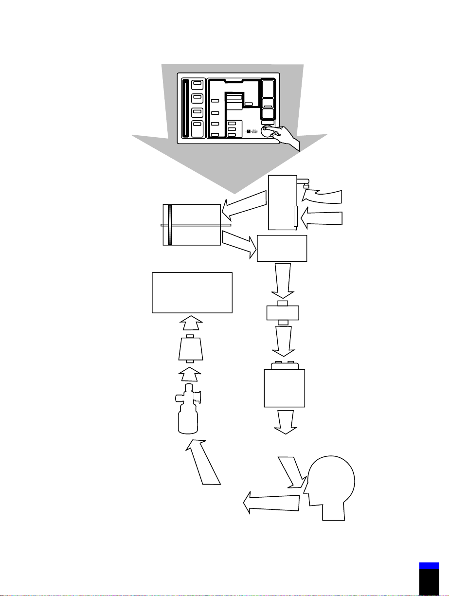
Introduction 1
………………………………………………………………….…
+
—
740 Ventilator
Keyboard
Regulator
Piston/cylinder
system
Exhalation/
PEEP/CPAP
system
Filter
Oxygen
Room air
Inspiration
manifold
Inspiratory
filter
Gas intake
system
Expiratory
filter
Humidification
device
Collector
vial
Ventilator breathing
circuit (inspiratory limb)
Patient
Ventilator breathing
circuit (expiratory limb)
7-00017
Figure 1-1. Block diagram: 700 Series Ventilator function
G-061874-00 Rev. D (09/00) 700 Series Ventilator Operator’s Manual
1-5

1 Introduction
The heated exhalation system monitors the flow of the patient’s exhaled gas using
a differential pressure transducer. The patient exhales through the exhalation
valve. During exhalation, the PEEP/CPAP system maintains user-selected
pressure in the ventilator breathing circuit.
Throughout the respiratory cycle, pressure transducers monitor inspiratory,
expiratory, and atmospheric pressures. The temperatures of the pneumatic
compartment and inspiratory gas are also monitored. Information from these
transducers is continuously used to update the calculations that control
ventilation. (Appendix F provides a diagram of the ventilator’s pneumatic system
and ventilator breathing circuit.)
Power to operate the ventilator comes from ac mains (wall) or battery power. The
power supply is designed to protect against excessive voltages, temperatures, or
current draws. A power cord retainer prevents the cord from accidental
disconnection.
The ventilator includes an internal battery, and accommodates an optional
external battery. Depending on the ventilator settings, battery backup power can
be supplied for up to 2 ½
the external battery. Both batteries are recharged during operation from ac power.
If both are installed, the external battery is used first when ac power is not
present. If the external battery is depleted or not installed, the internal battery
supplies power to the ventilator when ac power is not available. The keyboard
indicates the source of power and battery charge level of the internal battery at all
times.
hours using the internal battery, and up to 7 hours using
1-6
Emergency modes: The ventilator declares a ventilator inoperative (VENT INOP)
condition if a hardware failure or critical software error that could compromise
safe ventilation occurs. In case of a ventilator inoperative condition, the VENT
INOP indicator lights and the ventilator enters the safety valve open (SVO) state.
To correct a ventilator inoperative condition, the ventilator must be turned off,
then powered on again; at power-on, the operator must run extended self-test
(EST). The ventilator must pass EST before normal ventilation can resume.
The safety valve allows the patient to breathe room air unassisted when the
ventilator is in the SVO state. The ventilator remains in the SVO state until
power-on self-test (POST) verifies that power levels to the ventilator are
acceptable and that the motor controller and microcontrollers are functioning
correctly, and until the user has confirmed ventilator settings.
If the ventilator enters the SVO state and POST is not running, the SAFETY
VALVE OPEN indicator lights and a high-priority alarm sounds. The ventilator
enters the SVO state if it detects a hardware or software failure that could
700 Series Ventilator Operator’s Manual G-061874-00 Rev. D (09/00)

Introduction 1
………………………………………………………………….…
compromise safe ventilation. In case of a malfunction that prevents software from
opening the safety valve, there is also an analog circuit that opens the safety valve
when system pressure exceeds 115 cmH
If the ventilator detects an occlusion or a continuous high inspiratory pressure
condition, it opens the safety and exhalation valves to vent excess pressure, then
shuts them and begins occlusion cycling mode. In occlusion cycling mode the
ventilator uses current settings except for those summarized in Table 1-2. If the
ventilator again detects an occlusion or continuous high pressure condition, it
again opens the safety and exhalation valves then resumes occlusion cycling
mode. If the operator presses the alarm reset key or the ventilator does not detect
an occlusion or continuous high pressure condition, it reverts to normal
ventilation using the most recently accepted settings.
Table 1-2: Changes to current settings in occlusion cycling mode
Setting Change to setting
O (113 hPa).
2
HIGH PRESSURE
alarm (VCV breath
type)
PEEP (all modes) Set to 0 cmH2O
(all modes) Set to 100%
%O
2
SPONT mode (PSV
breath type)
SUPPORT
PRESSURE (PSV
breath type)
SUPPORT
PRESSURE (PCV
breath type)
RISE TIME FACTOR
(PCV breath type)
G-061874-00 Rev. D (09/00) 700 Series Ventilator Operator’s Manual
Setto30cmH
Breaths are delivered at a rate of 12/min with an inspiratory time
of 2 seconds.
If less than 15 cmH
If 15 cmH
If less than 15 cmH
If 15 cmH2O or above: the current setting is used (no change).
Set to 70%
O
2
O:setto15cmH2O.
2
O or above: the current setting is used (no change).
2
O:setto15cmH2O.
2
1-7

1 Introduction
1.2 Symbols and labels
These symbols and labels appear on the 700 Series Ventilator System:
Power switch positions per IEC 601-1.”I” represents ON position; “O”
represents OFF position.
7-00421
Refer to manual per IEC 601-1. When this symbol appears on
product, it means “Refer to documentation for information.”
7-00418
Potential equalization point, per IEC 601-1
7-00416
External battery connection
7-00426
Circuit breaker
1-8
7-00414
Serial number
SN
ac current
7-00427
Type B equipment, per IEC 601-1
7-00415
Indicates the degree of protection provided by enclosure (drip-proof).
IPX1
7-00403
700 Series Ventilator Operator’s Manual G-061874-00 Rev. D (09/00)
Introduction 1
………………………………………………………………….…
Signifies compliance with the Medical Device Directive, 93/42/EEC
7-00412
CSA and NRTL (Nationally Recognized Testing Laboratory)
certification, granted by CSA
8-00417
The TUV Rheinland logo signifies TUV Rheinland Type Test approval
to Annex III of the Medical Device Directive
7-00420
Exhaust port connector
EXHAUST
Inspiratory limb connector
TO
PATI EN T
Expiratory limb connector
FROM
PATI EN T
G-061874-00 Rev. D (09/00) 700 Series Ventilator Operator’s Manual
1-9
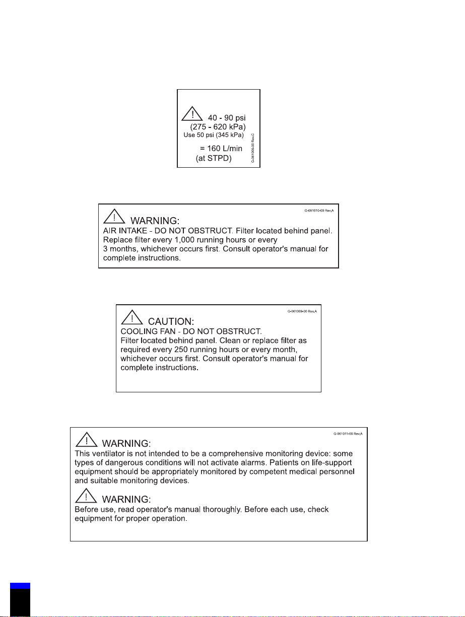
1 Introduction
Oxygen inlet port label
O
2
.
V
max
61006
Air intake label
61010
Cooling fan label
General life support equipment warning label
1-10
700 Series Ventilator Operator’s Manual G-061874-00 Rev. D (09/00)
61009
61011
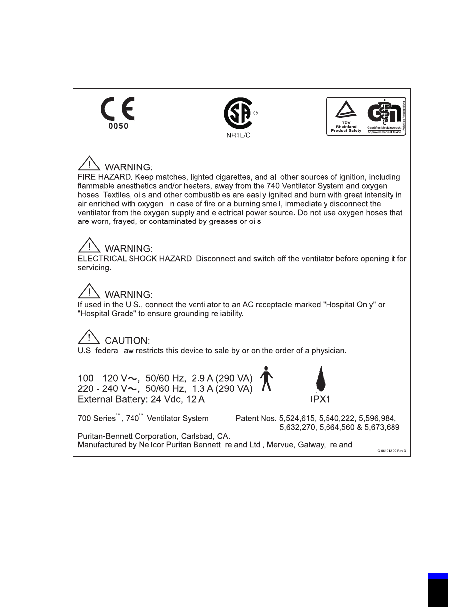
Introduction 1
………………………………………………………………….…
740 Ventilator back panel label
61012
G-061874-00 Rev. D (09/00) 700 Series Ventilator Operator’s Manual
1-11
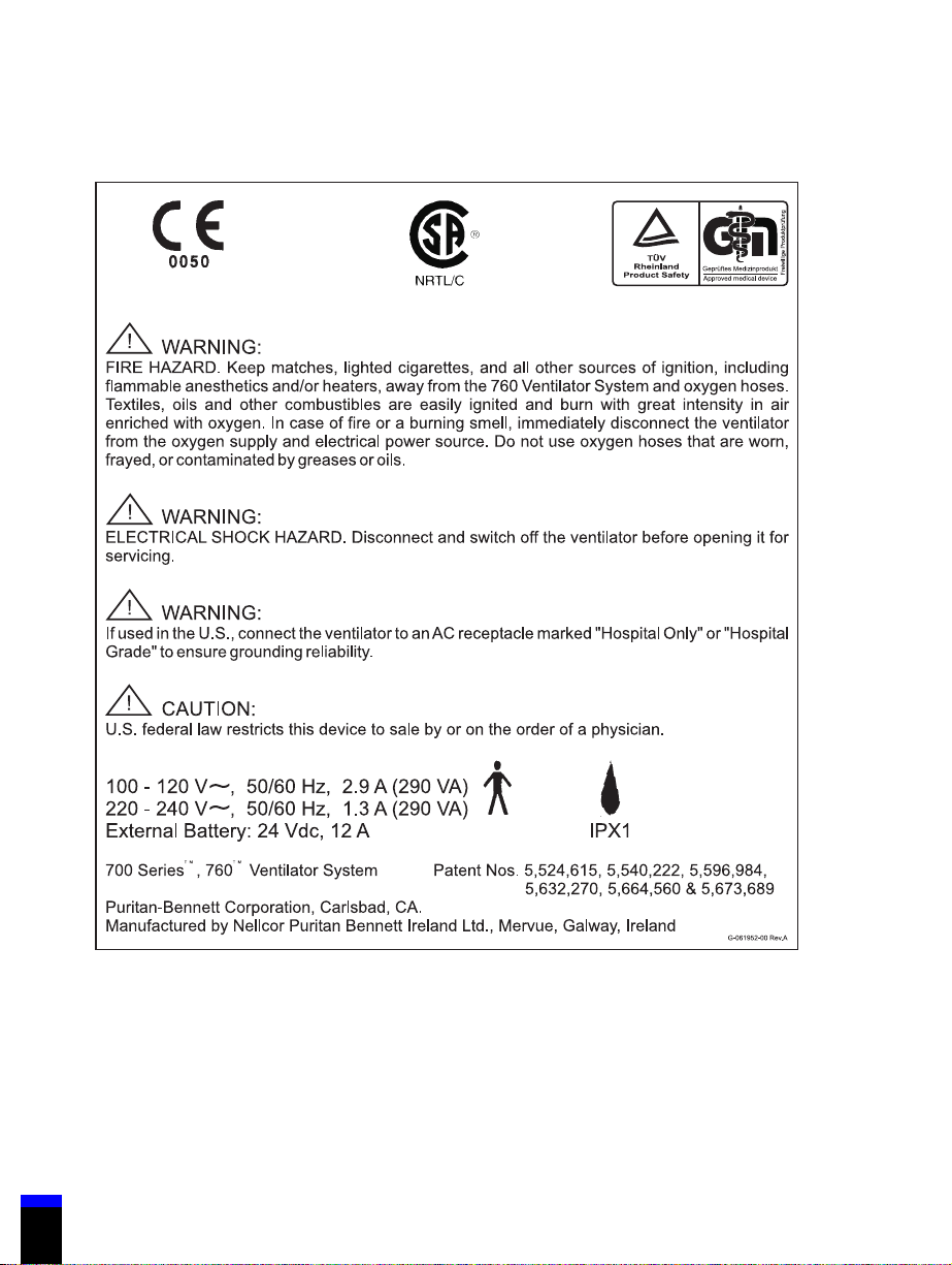
1 Introduction
760 Ventilator back panel label
1-12
61952
700 Series Ventilator Operator’s Manual G-061874-00 Rev. D (09/00)
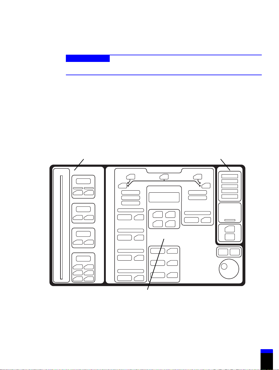
Introduction 1
………………………………………………………………….…
1.3 Keyboard
Caution
To avoid damaging the keyboard, do not press on it with sharp objects.
The keyboard (Figure 1-2 shows the 740 keyboard and Figure 1-3 shows the 760
keyboard) is grouped into three sections:
• VENTILATOR SETTINGS: Where you set breath delivery variables.
• PATIENT DATA: Where you set alarm limits and view the monitored
pressures, breath timing, and volumes.
• VENTILATOR STATUS: Where you see the alarm status and operating
condition of the ventilator.
Patient data Ventilator status
Ventilator settings
Figure 1-2. 740 Ventilator System keyboard
G-061874-00 Rev. D (09/00) 700 Series Ventilator Operator’s Manual
7-00048
1-13
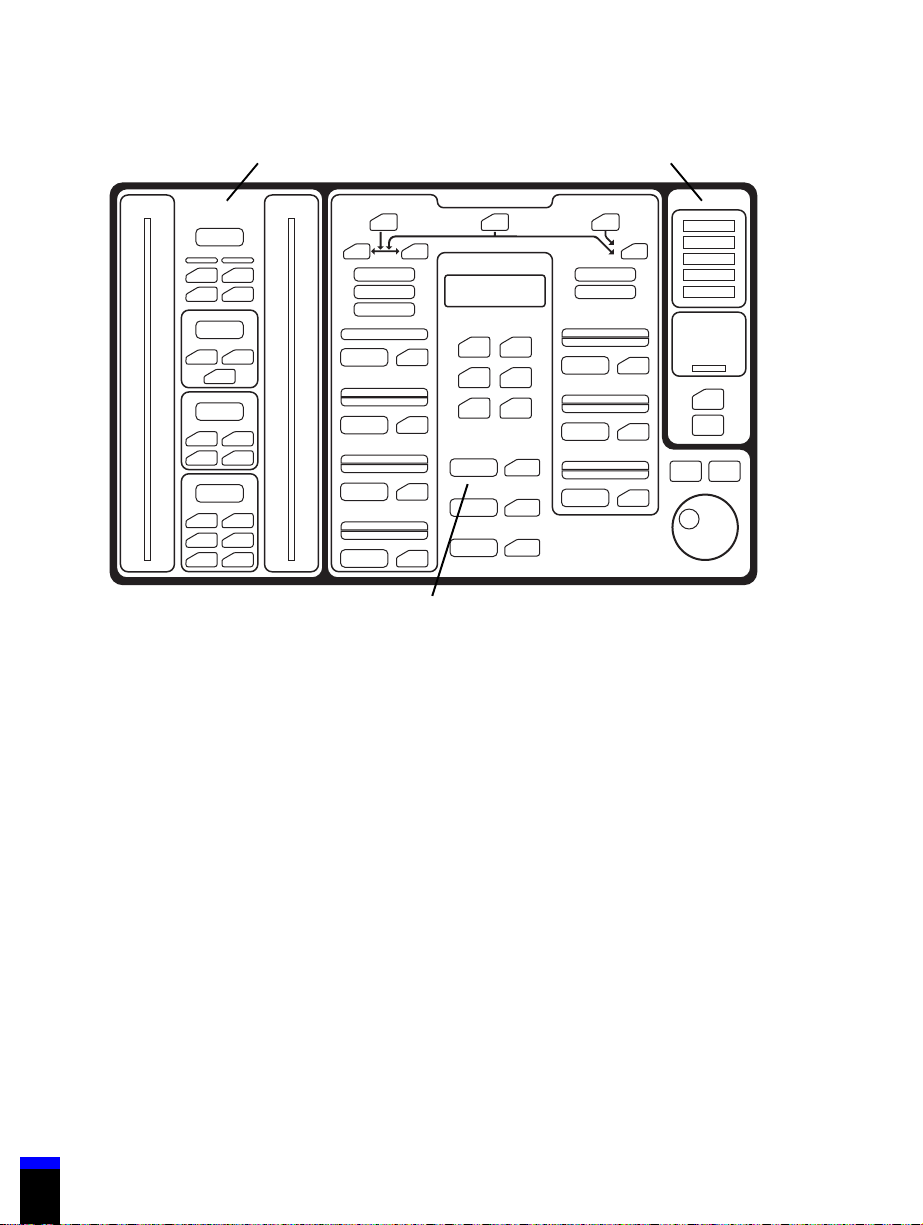
1 Introduction
Patient data Ventilator status
1-14
Ventilator settings
7-00123
Figure 1-3. 760 Ventilator System keyboard
1.3.1 VENTILATOR SETTINGS
The VENTILATOR SETTINGS section of the keyboard allows you to select the
ventilation mode, breath type, and settings. For more detail on ventilation modes
and breath delivery, see Appendix D.
To change the mode and settings, select the mode, then the breath type, and then
the ventilator settings. The keys flash during setup and mode changes to ensure
that you review all pertinent settings. The keyboard is designed to minimize
accidental or unintentional changes.
Table 1-3 summarizes the functions of the keys, knob, and indicators in the
VENTILATOR SETTINGS section of the keyboard. Ventilator settings are also
limited by these breath delivery boundaries:
• I:E ratio £ 4:1 for PCV (760 Ventilator only), £ 3:1 for all other breath types
• Inspiratory time = 0.2 to 8 seconds (excluding plateau)
• Expiratory time ³ 0.2 seconds
700 Series Ventilator Operator’s Manual G-061874-00 Rev. D (09/00)

Introduction 1
………………………………………………………………….…
• PEEP/CPAP + SUPPORT PRESSURE or INSPIRATORY PRESSURE £ 80
cmH
O (80 hPa)
2
NOTE:
Maximum SUPPORT PRESSURE is 70 cmH
INSPIRATORY PRESSURE is 80 cmH
2
• SUPPORT PRESSURE or INSPIRATORY PRESSURE + PEEP/CPAP
< HIGH PRESSURE — 2 cmH
O(2hPa)
2
• HIGH PRESSURE (in A/C and SIMV modes) > PEEP/CPAP +
7cmH
O(7hPa)
2
• HIGH PRESSURE (in SPONT mode) > PEEP/CPAP + SUPPORT
PRESSURE + 2 cmH
O(2hPa)
2
• HIGH PRESSURE > LOW INSP PRESSURE
• Minute volume £ 50 L/min at an I:E ratio of 2:1
Table 1-3: 700 Series Ventilator keyboards: VENTILATOR SETTINGS
O.
O, maximum
2
Key/indicator Specifies… Range
Mode/breath type settings
A/C Assist/control mode VCV (volume control ventilation)
and PCV (pressure control
ventilation) breath types.
(PCV available on 760 Ventilator
only.)
SIMV Synchronous intermittent
mandatory ventilation mode
SPONT Spontaneous mode PSV breath type
VCV VCV breath type VCV available on 740 and 760
PCV PCV breath type PCV available on 760 Ventilator
G-061874-00 Rev. D (09/00) 700 Series Ventilator Operator’s Manual
VCV, PCV (760 only), and PSV
(pressure support ventilation)
breath types.
Ventilators in A/C or SIMV
modes.
only in A/C or SIMV modes.
1-15

1 Introduction
Table 1-3: 700 Series Ventilator keyboards: VENTILATOR SETTINGS (continued)
Key/indicator Specifies… Range
PSV PSV breath type PSV available in SIMV or
SPONT modes.
Mandatory (VCV) settings
RESPIRATORY
RATE
TIDAL
VOLUME
PEAK FLOW Maximum flow of gas delivered
PLATEAU (s) Length of inspiratory pause after a
Mandatory (PCV) settings (760 Ventilator only)
RESPIRATORY
RATE
The minimum number of
mandatory breaths the patient
receives per minute. During apnea
ventilation the minimum
RESPIRATORY RATE setting is 6 /
minute.
Volume delivered to the patient
during a mandatory breath,
compliance-compensated and
corrected to body temperature and
pressure, saturated (BTPS).
during a mandatory breath (BTPS).
(Combined with tidal volume, peak
flow defines the active portion of
inspiratory time.)
mandatory breath has been
delivered, during which no gas is
delivered.
The minimum number of
mandatory breaths the patient
receives per minute. During apnea
ventilation the minimum
RESPIRATORY RATE setting is 6 /
minute.
1to70/minute
Accuracy: ± (0.1 + 1%) /minute
40 to 2000 ml
Accuracy: ± (10 ml + 10% of
setting)
3to150L/min
Accuracy: ± (5 + 10% of setting)
L/min
0.0to2.0second
Accuracy: ± 0.05 second
1to70/minute
Accuracy: ± (0.1 + 1%) /minute
INSPIRATORY
PRESSURE
(760 only)
1-16
Pressure above PEEP during the
inspiratory phase of a PCV breath.
700 Series Ventilator Operator’s Manual G-061874-00 Rev. D (09/00)
5to80cmH
Accuracy: ± (3 + 2.5% of setting)
O
cmH
2
O(5to80hPa)
2

Introduction 1
………………………………………………………………….…
Table 1-3: 700 Series Ventilator keyboards: VENTILATOR SETTINGS (continued)
Key/indicator Specifies… Range
TI/I:E RATIO
(760 only)
RISE TIME
FAC TOR
(760 only)
NOTE:
To help determine the correct setting for inspiratory time, during PCV the message
window displays peak inspiratory flow, end inspiratory flow, and end exhalation flow
in L/min.
YoucanusetheMENUkeyto
select inspiratory time (T
ratio as the breath timing setting for
a PCV breath. You can change the
selected breath timing setting (T
I:E ratio), but the setting remains
constant when you change the
respiratory rate in PCV.
Selecting I:E ratio makes the set
ratio of inspiratory time to
expiratory time for a PCV breath.
Thetimeforinspiratorypressureto
rise from 0 to 95% of the target
pressure level during a PCV
breath.
A setting of 100 = a 100-ms rise
time, and a setting of 5 = 80% of
the inspiratory time or 2500 ms,
whichever is less.
When you adjust this setting, the
message window shows the actual
time (in seconds) to reach 95% of
target pressure.
)orI:E
I
or
I
Inspiratory time (T
0.2 to 8 seconds
Accuracy: ± 0.05 second
I:E ratio:
Accuracy: ± (0.1 + 2%)
5to100
£ 4:1
):
I
G-061874-00 Rev. D (09/00) 700 Series Ventilator Operator’s Manual
1-17

1 Introduction
Table 1-3: 700 Series Ventilator keyboards: VENTILATOR SETTINGS (continued)
Key/indicator Specifies… Range
Spontaneous (PSV) settings
SUPPORT
PRESSURE
RISE TIME
FAC TOR
(760 only)
Pressure above PEEP maintained
during spontaneous inspiration.
Support pressure is terminated
when inspiratory flow falls to 25%
of peak inspiratory flow, or to the
exhalation sensitivity setting (760
only), or 10 L/min or 25% of peak
flow, whichever is lower (740 only).
Maximum inspiratory time is 3.5
seconds for adults, and 2.5
seconds for pediatric patients.
Thetimeforinspiratorypressureto
rise from 0 to 95% of the target
pressure level during a PSV breath.
A setting of 100 = a 100-ms rise
time, and a setting of 5 = 80% of
the inspiratory time or 1500 ms
(when adult ventilator breathing
circuit is selected) or 600 ms (when
pediatric circuit is selected),
whichever is less.
When you adjust this setting, the
message window shows the actual
time (in seconds) to reach 95% of
target pressure.
0to70cmH
Accuracy: ± (3 + 2.5% of setting)
O
cmH
2
5to100
O(0to70hPa)
2
1-18
700 Series Ventilator Operator’s Manual G-061874-00 Rev. D (09/00)

Introduction 1
………………………………………………………………….…
Table 1-3: 700 Series Ventilator keyboards: VENTILATOR SETTINGS (continued)
Key/indicator Specifies… Range
EXH
SENSITIVITY
(760 only)
Common settings
PEEP/CPAP Positive end expiratory pressure/
The percent of peak expiratory flow
at which the ventilator cycles from
inspiration to exhalation for
spontaneous breaths. The flow at
which the ventilator cycles from
inspiration to exhalation for PSV
breaths. Exhalation begins when
the inspiratory flow is less than the
set value.
To help set EXH SENSITIVITY
appropriately, the peak inspiratory
flow and end inspiratory flow are
displayed in the message window
in PSV. (To ensure accurate
estimates of these flows, it is
important to run SST so that tubing
compliance calculations are
correct.)
continuous positive airway
pressure. Minimum pressure
maintained during inspiratory and
expiratory phases.
1to80%
0to35cmH
Accuracy:
± (2 cmH
O + 4% of setting)
2
O(0to35hPa)
2
TRIGGER
SENSITIVITY
(L/min)
%O
2
Inspiratory flow required to trigger
the ventilator to deliver a breath.
Percentage of inspired oxygen of
the gas delivered to the patient.
1to20L/min
21 to 100%
Accuracy: ± 3% full scale
NOTE:
It may take several minutes for the oxygen percentage to
stabilize.
G-061874-00 Rev. D (09/00) 700 Series Ventilator Operator’s Manual
1-19

1 Introduction
Table 1-3: 700 Series Ventilator keyboards: VENTILATOR SETTINGS (continued)
Key/indicator Specifies… Range
Other keys, knobs, and indicators
APNEA
PA RA MS k ey
AllowsyoutoselectVCVorPCV(760 Ventilator only) apnea ventilation,
and the apnea ventilation settings. The apnea interval is adjustable from
10 to 60 seconds. Apnea ventilation is available in all modes. For apnea
parameter ranges, see mandatory VCV settings and mandatory PCV
(760 Ventilator only) settings.
MENU Allows you to view active and reset alarms, run SST and EST, adjust
certain settings (including alarm volume, PCV timing, volume bar graph
display, endotracheal tube size, and date and time), access oxygen
sensor functions (calibrate, enable or disable % O
alarm limits, and
2
enable or disable display of oxygen sensor reading), enter standby
mode, view battery information, display software revision, display
service information, and enter EasyNeb nebulizer functions. (Section 6
tells you how to use the menu function.)
100% O
2
Switches the % O2to 100% for 2 minutes, then returns to the current %
setting. The 2-minute interval restarts every time you press 100%
O
2
O
. Once the 100% O2has started, you can press CLEAR to stop the
2
maneuver (unless you have entered a MENU key function or selected a
setting).
MANUAL INSP Delivers one mandatory breath to the patient according to the current
mandatory settings (in A/C or SIMV) or the current apnea parameters (in
SPONT). You can deliver a MANUAL INSP at any time during the
exhalation phase of a breath as long as the exhaled flow is less than
30% of the peak exhaled flow, except during apnea ventilation.
1-20
700 Series Ventilator Operator’s Manual G-061874-00 Rev. D (09/00)

Introduction 1
………………………………………………………………….…
Table 1-3: 700 Series Ventilator keyboards: VENTILATOR SETTINGS (continued)
Key/indicator Specifies… Range
EXP PAUSE
(760 only)
Allows you to measure the patient’s auto-PEEP. An EXP PAUSE
maneuver causes the ventilator to close the exhalation valve at the end
of the expiratory phase, and not deliver the next mandatory breath. At
the end of the maneuver, the message window shows the calculated
value for auto-PEEP (expiratory pressure at the beginning of the
maneuver minus expiratory pressure at the end of the maneuver) and
total PEEP for 30 seconds.
The message window shows the end expiratory flow in L/min at the
beginning of each breath. If there is expiratory flow when the ventilator
delivers the next breath, auto-PEEP is present.
The EXP PAUSE continues as long as you hold down the key, and
should last only until expirator y pressure stabilizes. An EXP PAUSE
maneuver ends when you release the key, the patient initiates a breath,
an alarm occurs, the expiratory phase (including the maneuver) lasts
more than 20 seconds, or the ventilator detects a leak.
Auto-PEEP:
Range: 1 to 35 cmH
Accuracy: ± (1 cmH
The EXP PAUSE maneuver is unavailable when the RESPIRATORY
RATE setting is less than 3 /minute.
O.
2
O + 3% of reading).
2
G-061874-00 Rev. D (09/00) 700 Series Ventilator Operator’s Manual
1-21

1 Introduction
Table 1-3: 700 Series Ventilator keyboards: VENTILATOR SETTINGS (continued)
Key/indicator Specifies… Range
Other keys, knobs, and indicators (continued)
INSP PAUSE
(760 only)
Allows you to measure the patient’s compliance and resistance. An
extended inspiratory pause also allows you to expand the patient’s lungs
forupto10seconds.
Pressing INSP PAUSE momentarily causes the ventilator to wait until
the end of the inspiratory phase of the current or next mandatory breath
(in SPONT mode, the ventilator delivers a mandatory breath using the
MANUAL INSP key according to the apnea settings), stop breath
delivery, and keep the exhalation valve closed. The INSP PAUSE
continues until the ventilator detects a stable plateau pressure or 2
seconds have elapsed. An INSP PAUSE maneuver ends when a stable
plateau is reached or an alarm occurs.
Pressing INSP PAUSE for 2 or more seconds after the pause begins
causes the ventilator to deliver an inspiratory pause for as long as you
hold down the key. An extended INSP PAUSE maneuver ends when you
release the key or 10 seconds have elapsed.
You can press CLEAR or release the INSP PAUSE key at any time to
cancel an INSP PAUSE maneuver, and alarms cancel the maneuver.
At the end of the breath, the message window shows the calculated
value for compliance and resistance (if the mandatory breath was a VCV
breath) or compliance (if the mandatory breath was a PCV breath) for 30
seconds.
Compliance:
Range: 1 to 150 mL/H
Accuracy: ± (1 mL/cmH
O.
2
O + 20% of reading).
2
Resistance:
Range: 0 to 150 cmH
Accuracy: ± (3 cmH
O/L/second.
2
O/L/second + 20% of reading).
2
CLEAR Pressing CLEAR before accepting a setting cancels the proposed
setting. Pressing CLEAR does not cancel accepted settings.
Pressing CLEAR twice returns the ventilator to its previous state (unless
you have entered a MENU key function that requires you to press
CLEAR more times).
Pressing CLEAR during a 100% O2maneuver cancels the maneuver.
1-22
700 Series Ventilator Operator’s Manual G-061874-00 Rev. D (09/00)

Introduction 1
………………………………………………………………….…
Table 1-3: 700 Series Ventilator keyboards: VENTILATOR SETTINGS (continued)
Key/indicator Specifies… Range
Other keys, knobs, and indicators (continued)
ACCEPT Makes changes to settings effective. If you don’t press ACCEPT within
30 seconds of proposing a new setting, the user interface returns to its
previous state.
Knob Adjusts the value of a setting or selects a menu option. A setting value
that flashes means that the knob is linked to that setting. Turning the
knob clockwise increases the value, and turning the knob
counterclockwise decreases the value.
CURRENT Lights when the ventilator is operating according to the displayed
settings, or during apnea ventilation. (There is one indicator for
mandatory breaths, and one for spontaneous breaths.)
PROPOSED Lights when you propose a mode or breath type, or you are setting
apnea parameters. Once a proposed setting is accepted, it becomes
effective at the next breath.
APNEA
PA RA MS
indicator
Message
window
G-061874-00 Rev. D (09/00) 700 Series Ventilator Operator’s Manual
Lights when apnea ventilation is active.
Lights with PROPOSED indicator when you are setting apnea
parameters, and both indicators turn off once apnea parameters are
accepted.
Shows up to four lines of information (20 characters per line).
First line: Reserved for the highest-priority active or autoreset alarm. On
the 760 Ventilator only, if no alarm is active and the display of the oxygen
sensor reading is enabled, the % O
VCV is the current or proposed breath type and there are no active or
autoreset alarms, shows the selected VCV flow pattern (ramp or
square).
Second line: Information about the menu function or settings, alarm
silence time remaining, or current date and time. During normal
ventilation, shows “Flow (L/min).”
Third and fourth lines: Reserved for other messages. For every breath
type, peak and end inspiratory flows are displayed on the third line, and
end expiratory flow is displayed on the fourth line (except that inspiratory
flow is not displayed during VCV breaths or VCV apnea ventilation).
is displayed here. Otherwise, if
2
1-23

1 Introduction
1.3.2 PATIENT DATA
The PATIENT DATA section of the keyboard allows you to view the pressure,
breath timing, and volume of the patient’s breath. You can also view the alarm
settings. A lighted key indicates that a measurement is selected, and its value
appears in the display window. Values are continuously displayed and updated
during ventilation.
Table 1-4 summarizes the functions of the keys and indicators in the PATIENT
DATA section of the keyboard.
Table 1-4: 700 Series Ventilator keyboards: PATIENT DATA
Key/
indicator
Pressure
MEAN
PRESSURE
PEAK
PRESSURE
PLATEAU
PRESSURE
(760 only)
PEEP/CPAP
(760 only)
Function Range
Shows the calculated value of ventilator
breathing circuit pressure over an entire
respiratory cycle. Updated at the
beginning of each breath.
Shows the maximum pressure measured
during inspiration. Updated at the
beginning of each expiratory phase.
(Default pressure display.)
Shows the pressure measured at the end
of the plateau period of a mandatory
inspiration (whether the inspiration is in a
regular VCV breath or is part of an
inspiratory pause maneuver). Updated at
the beginning of each expiratory phase.
The PRESSURE display shows a blank if
the ventilator does not detect a stable
plateau pressure.
Shows the pressure measured at the
expiratory limb before any inspiratory
effort. Updated at the beginning of each
inspiratory phase.
0to99cmH
Accuracy:
± (3 + 4% of reading) cmH2O
0to140cmH
Accuracy:
± (3 + 4% of reading) cmH
0to140cmH
Accuracy:
± (3 + 4% of reading) cmH
0to140cmH
Accuracy:
± (3 + 4% of reading) cmH
O(0to99hPa)
2
O(0to140hPa)
2
O(0to140hPa)
2
O(0to140hPa)
2
2
2
2
O
O
O
1-24
700 Series Ventilator Operator’s Manual G-061874-00 Rev. D (09/00)

Introduction 1
………………………………………………………………….…
Table 1-4: 700 Series Ventilator keyboards: PATIENT DATA (continued)
Key/
indicator
Breath timing
RATE (/min) Shows the calculated value of the total
respiratory rate, based on the previous 60
seconds or 8 breaths (whichever interval
is shorter). Updated at the beginning of
each breath. (Default breath timing
display.)
The calculation is reset (and display is
blank) when ventilation starts, when
apnea ventilation starts or autoresets,
when you change the mode, breath type,
or RESPIRATORY RATE setting, and
whenyoupressthealarmresetkey.
I:E RATIO Shows the ratio of measured inspiratory
time to measured expiratory time.
Updated at the beginning of each breath.
INSP
TIME(s)
(760 only)
The measured inspiratory time, including
breaths that are truncated due to a HIGH
PRESSURE alarm. Updated at the
beginning of each expiratory phase.
Function Range
1 to 199 /minute
Accuracy:
± (0.1 +1% of reading)/minute
1:99.9 to 9.9:1
Accuracy:
± (0.1 + 2%)
0.1 to 9.90 seconds
Accuracy:
± 0.05 seconds
Vol ume
EXHALED
VOLUME
(ml)
G-061874-00 Rev. D (09/00) 700 Series Ventilator Operator’s Manual
Shows the patient’s measured expiratory
tidal volume averaged over the last 5
breaths (for A/C VCV breaths, ventilatorinitiated PCV breaths, and PCV apnea
breaths) or for the just-completed breath
(for all other breaths). Corrected to BTPS
and compliance-compensated. Updated
at the beginning of each inspiration.
(Default volume display.)
The calculation is reset when ventilation
starts, when apnea ventilation starts or
autoresets, when you change the mode or
breath type, and when you press the
alarm reset key.
0to9L
Accuracy:
± (10 ml + 10% of reading)
1-25

1 Introduction
Table 1-4: 700 Series Ventilator keyboards: PATIENT DATA (continued)
Key/
indicator
Volume (continued)
TOTAL
MINUTE
VOLUME (L)
DELIVERED
VOLUME
(ml)
(760 only)
SPONT
MINUTE
VOLUME (L)
(760 only)
Shows the patient’s measured expiratory
minute volume, based on the previous 60
seconds or 8 breaths (whichever interval
is shorter). Updated at the beginning of
each breath.
The calculation is reset when ventilation
starts, when apnea ventilation starts or
autoresets, when you change the mode or
breath type, and when you press the
alarm reset key.
Shows the measured inspiratory tidal
volume for the just-completed PCV or PSV
breath. Corrected to BTPS and
compliance-compensated. Updated at the
beginning of each inspiration for PCV and
PSV breath types.
Shows the patient’s measured expiratory
minute volume for all spontaneous
breaths, based on the previous 60
seconds or 8 breaths (whichever interval
is shorter). Updated at the beginning of
each breath.
The calculation is reset when ventilation
starts, when apnea ventilation starts or
autoresets, when you change the mode or
breath type, and when you press the
alarm reset key.
Function Range
0to99L
Accuracy:
± (10 ml + 10% of reading)
0 to 3000 ml
Accuracy:
± (10 ml + 10% of reading)
0to99L
Accuracy:
± (10 ml + 10% of reading)
1-26
700 Series Ventilator Operator’s Manual G-061874-00 Rev. D (09/00)

Introduction 1
………………………………………………………………….…
Table 1-4: 700 Series Ventilator keyboards: PATIENT DATA (continued)
Key/
indicator
Alarm settings
HIGH RATE An active alarm indicates that measured
respiratory rate is higher than the alarm
setting.
HIGH TIDAL
VOLUME
LOW INSP
PRESSURE
LOW TIDAL
VOLUME
HIGH
PRESSURE
An active alarm indicates that exhaled
volume for three out of four consecutive
breaths was above the alarm setting.
An active alarm indicates that monitored
circuit pressure is below the alarm setting
at the end of inspiration. Inactive in for any
spontaneous breath.
An active alarm indicates that delivered
volume for three out of four consecutive
breaths were below the alarm setting. (If
this alarm is set to 0 ml and breath type is
PCV, an active alarm indicates that
delivered volume is less than 3 ml for three
out of four consecutive breaths.)
An active alarm indicates that two
consecutive breaths were truncated
because circuit pressure reached the
alarm setting.
Function Range
3 to 100 /minute
Accuracy:
± (0.1 +1% of setting)/minute
20 to 6000 ml
Accuracy:
± (10 ml + 10% of setting)
3to60cmH
Accuracy:
± (1 + 3% of setting)
0 to 2000 ml
Accuracy:
± (10 ml + 10% of setting)
10 to 90 cmH
(10to90hPa)
Accuracy:
± (1 + 3% of setting)
O(3to60hPa)
2
O
2
LOW
MINUTE
VOLUME
G-061874-00 Rev. D (09/00) 700 Series Ventilator Operator’s Manual
An active alarm indicates that monitored
minute volume is less than the alarm
setting, based on an eight-breath running
average or the previous minute, whichever
is less.
0to50L
Accuracy:
± (10 ml + 10% of setting)
1-27

1 Introduction
Table 1-4: 700 Series Ventilator keyboards: PATIENT DATA (continued)
Key/
indicator
Other indicators
Pressure bar
graph
Volume bar
graph
(760 only)
MAND Lights at the start of each breath to
Shows real-time pressures in centimeters
of water (cmH2O) or hectopascals (hPa).
LEDs show the current HIGH PRESSURE
alarm setting and the peak pressure of the
last breath during exhalation.
Shows real-time exhaled volume in
milliliters (ml). Volumes are compliancecompensated and corrected to BTPS.
The active scale is determined by the
HIGH TIDAL VOLUME alarm setting.
LEDs show the current HIGH TIDAL
VOLUME and LOW TIDAL VOLUME
alarm settings. You can use the MENU key
to enable or disable the volume bar graph.
During exhalation, LEDs show the
maximum exhaled volume of the last
breath.
indicate a ventilator- or operator-initiated
(time or manually triggered) mandatory
breath is being delivered.
Function Range
-10to90cmH
(-10to90hPa)
Resolution: 1 cmH2O(1hPa)
If HIGH TIDAL VOLUME
setting < 500 ml: 0 to 500 ml
Resolution: 5 ml
If HIGH TIDAL VOLUME
setting >
Resolution: 20 ml
Not applicable
O
2
500ml:0to2000ml
ASSIST Lights at the start of each breath to
indicate a patient-initiated mandatory (flow
triggered) breath is being delivered.
SPONT Lights at the start of each breath to
indicate a patient-initiated spontaneous
(flow triggered) breath is being delivered.
1.3.3 VENTILATOR STATUS
The VENTILATOR STATUS section of the keyboard shows the operating
condition of the ventilator, and is continuously updated during operation. Table
1-28
700 Series Ventilator Operator’s Manual G-061874-00 Rev. D (09/00)
Not applicable
Not applicable

Introduction 1
………………………………………………………………….…
1-5 summarizes the functions of the keys and indicators in the VENTILATOR
STATUS section of the keyboard.
Table 1-5: 700 Series Ventilator keyboards: VENTILATOR STATUS
Key/indicator Color Function
ALARM Red
(high priority)
CAUTION Yellow
(medium priority)
NORMAL Green Lights when no alarm condition is present.
VENT INOP Red
(high priority)
SAFETY VALVE
OPEN
Red
(high priority)
Flashes when a high-priority alarm is active. A
repeating sequence of three, then two beeps
sounds. Lights steadily when a high-priority
alarm has been autoreset.
Flashes when a medium-priority alarm is active.
A repeating sequence of three beeps sounds.
Lights steadily when a medium-priority alarm
has been autoreset.
Lights to indicate that the ventilator is
inoperative, and the ventilator safety valve is
open. A qualified service technician must run
and pass the extended self-test (EST) before
normal ventilation can resume.
If the condition that caused the safety valve to
open no longer exists, and the VENT INOP
indicator is off, press the alarm reset key to
resume ventilation.
Lights when the ventilator’s safety valve and
exhalation valve open and only room air is
available to the patient.
Can indicate that the ventilator is inoperative, or
there is an occlusion in the ventilator breathing
circuit. If possible, the message window shows
the alarm that triggered the safety valve open
condition and how much time has elapsed since
the last breath was triggered.
ON AC/
BATTERY
CHARGING
ON INTERNAL
BATTERY
G-061874-00 Rev. D (09/00) 700 Series Ventilator Operator’s Manual
Green Lights when the ventilator is running on ac
power and the battery is charging.
Yellow Flashes when the ventilator is running on the
internal battery.
1-29
1 Introduction
Table 1-5: 700 Series Ventilator keyboards: VENTILATOR STATUS (continued)
Key/indicator Color Function
ON EXTERNAL
BATTERY
INTERNAL
BATTERY
LEVEL
7-00423
7-00424
Yellow Flashes when the ventilator is running on the
external battery.
Green Shows the relative charge level of the internal
battery.
Ye l l o w Alarm silence: Silences the alarm sound for 2
minutes from the most recent key press.
Not applicable Alarm reset: Reestablishes all alarm indicators,
cancels the alarm silence period, and resets the
patient data displays. If the condition that
caused the alarm still exists, the alarm
reactivates. Cancels apnea ventilation, if active.
Reestablishes previous settings and ventilation
resumes, unless the ventilator is inoperative.
1-30
700 Series Ventilator Operator’s Manual G-061874-00 Rev. D (09/00)

SECTION
Setting up the ventilator 2
2
…………………………………………………………..……….
This section tells you how to set up the ventilator, including:
• Connecting and using the internal and external batteries
• Connecting the electrical supply
• Connecting the oxygen supply
• Connecting the ventilator breathing circuit
• Installing the collector vial
• Installing the flex arm
• Installing the humidifier
• Using the ventilator cart
Warning
• To avoid tipping or damaging the ventilator, do not stack other
equipment on the ventilator. 700 Series Ventilators are designed
to be mounted on either a cart or a shelf by a qualified service
technician. When lifting the ventilator, lift from the base, and use
assistance and appropriate safety precautions. Figure 2-1 shows
proper lifting technique.
• To avoid the possibility of injury to the patient and to ensure
proper ventilator operation, do not attach any device to the port
labeled “EXHAUST” unless the device is specifically authorized
by Mallinckrodt.
• To minimize the increased risk of fire due to an oxygen-enriched
environment, do not use the ventilator in a hyperbaric chamber.
• To avoid raising the oxygen concentration of room air, use the
ventilator in an adequately ventilated room.
Caution
Do not obstruct the cooling fan
G-061874-00 Rev. D (09/00) 700 Series Ventilator Operator’s Manual
.
2-1
2 Setting up the ventilator
Use two people to lift
Lift ventilator from base only
7-00053
Figure 2-1. Lifting the ventilator
2.1 Connecting and using internal and external batteries
Warning
A Mallinckrodt battery must always be installed in the ventilator.
Without a battery, the ventilator is not protected against low or lost
ac power. Do not use the ventilator unless a battery with at least
minimal charge is installed.
2-2
NOTE:
If the ventilator has been stored for an extended period, allow it to
acclimate to its environment before turning it on. This helps ensure
that the ventilator powers up correctly.
Every 700 Series Ventilator System includes an internal battery as a backup
power supply that comes standard with the ventilator. The internal battery can
provide up to 2
½ hours of backup power, depending on ventilator settings and
battery charge level. The ventilator operates on backup power when ac power is
lost or drops below minimum. The internal battery’s charge level is continuously
700 Series Ventilator Operator’s Manual G-061874-00 Rev. D (09/00)
Setting up the ventilator 2
…………………………………………………………………….
indicated on the keyboard (see Figure 2-2). The ventilator alarms when it
determines that only 5 minutes of power remain using the current settings.
Internal battery level
7-00054
Figure 2-2. Internal battery charge indicator
The optional external battery supplies up to 7 additional hours of backup power in
case ac power is lost or falls below minimum. (See Appendix B for external
battery ordering information.) If installed, the external battery is the first source
of backup power. The ventilator uses the internal battery if the external battery is
depleted or is not connected.
NOTE:
When the ventilator switches off because battery charge is
inadequate, turn off the power switch to prevent the battery from
being fully depleted. Connect the ventilator to ac power as soon as
possible.
The ventilator charges the internal and external batteries during ac power
operation, or in standby mode when attached to ac power. (See Appendix C for
battery specifications.) When the ventilator is operating on battery, you can use
the MENU key to check the estimated operational time remaining until recharge
is required for the internal and external batteries. (Section 6 tells you how to use
the MENU key.) The ventilator must operate for 2 minutes before it can estimate
battery time remaining.
You can disconnect and connect the external battery during normal operation.
When operating the ventilator on battery power, you can install the external
G-061874-00 Rev. D (09/00) 700 Series Ventilator Operator’s Manual
2-3

2 Setting up the ventilator
battery on the cart for easy transport. Follow these steps to connect the external
battery:
1. Mount the external battery on the base of the cart (or other suitable
location).
2. Plug the external battery’s cable into the connector (Figure 2-3).
3. Figure 2-4 shows you how to disconnect the external battery.
To ensure that the batteries retain their charge, store the ventilator in standby
mode, with its power switch on, and connected to ac power. If the ventilator is not
stored in this manner, check battery charge levels before using the ventilator.
Caution
If you plan to store the ventilator for more than 6 months, remove
batteries before storage. Replace the internal battery before using
the ventilator again. A qualified service technician must replace the
battery according to the instructions in the 700 Series Ventilator
System Service Manual.
If you turn on the ventilator after it has been unplugged for an extended period,
the LOW EXT BATTERY and LOW INT BATTERY alarms may become active.
If so, recharge the internal battery by leaving the ventilator plugged in and turned
on in standby mode (with no patient connected) for up to 8 hours.
2-4
If the LOW EXT BATTERY, LOW INT BATTERY, or BAT NOT CHARGING
alarm is still active after 8 hours, replace the batteries. If you turn off the
ventilator when the battery is absent or inadequately charged, a LOSS OF
POWER alarm sounds for at least 2 minutes.
NOTE:
The ON BATTERY indicator flashes when the ventilator is operating
on battery power.
700 Series Ventilator Operator’s Manual G-061874-00 Rev. D (09/00)
Setting up the ventilator 2
…………………………………………………………………….
External
battery
connector
External
battery
7-00055
Figure 2-3. Plugging the external battery into the ventilator
G-061874-00 Rev. D (09/00) 700 Series Ventilator Operator’s Manual
2-5
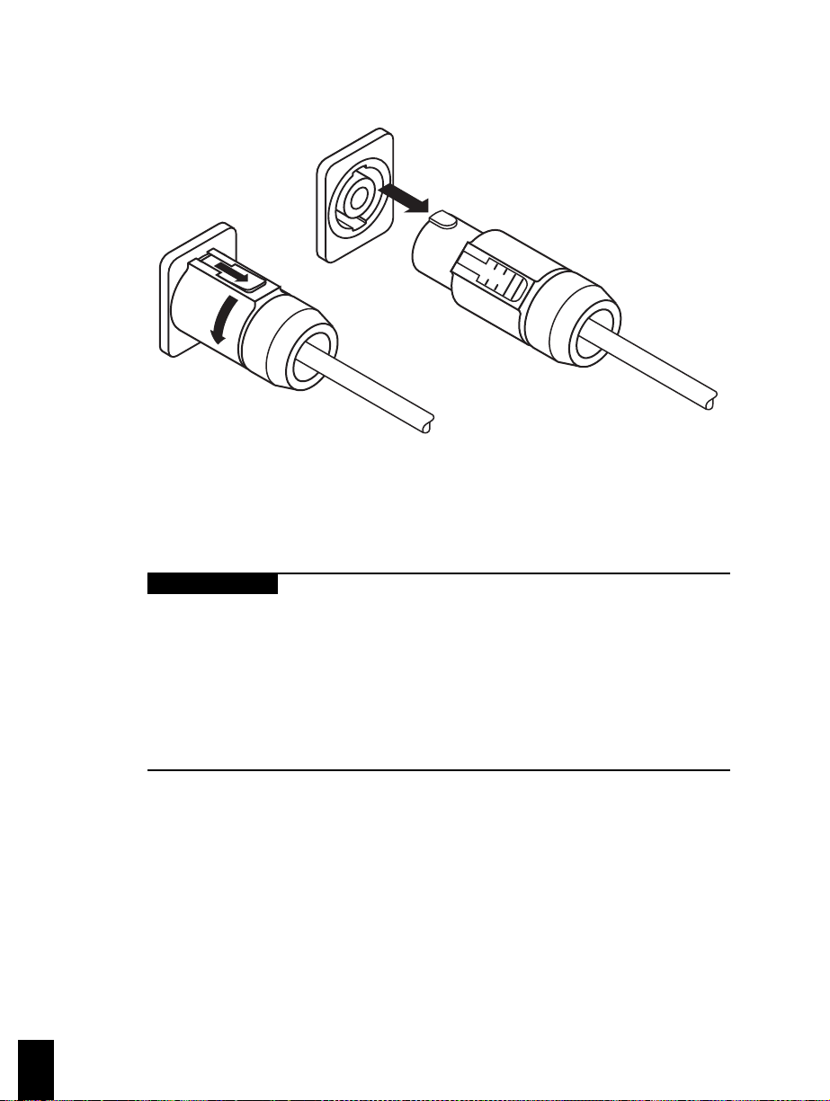
2 Setting up the ventilator
7-00051
Figure 2-4. Disconnecting the external battery
2.2 Connecting the electrical supply
Warning
• To avoid electrical shock hazard, connect the ventilator power
cord into a grounded ac power outlet. If the integrity of the ac
ground is in question, operate the ventilator from the internal or
external battery.
• If used in the U.S., connect the ventilator to an ac receptacle
marked “Hospital Only” or “Hospital Grade” to ensure grounding
reliability.
2-6
Every 700 Series Ventilator System is supplied with a power cord. A power cord
retainer covers the connector and socket to protect against liquid spills or
accidental disconnection.
When the ventilator is ready for operation on ac power, connect the power cord to
ac power (see Figure 2-5).
700 Series Ventilator Operator’s Manual G-061874-00 Rev. D (09/00)
перейти к содержанию
Medtronic Puritan Bennett 980 Аппарат ИВЛ NIV Plus Программное обеспечение

Аппарат ИВЛ Puritan Bennett™ 980 включает программное обеспечение NIV+. Он работает с программным обеспечением Neo Mode 2.0, обеспечивая функцию калибровки NIV+ на экране дополнительных настроек аппарата ИВЛ Puritan Bennett™ 980. Эта калибровка NIV+ дополняет, но не заменяет SST.
ОСНОВНЫЕ ХАРАКТЕРИСТИКИ
Программное обеспечение NIV+ предназначено для измерения давления в конце вдоха и выдоха на интерфейсе пациента. Это дает ценную информацию для клинициста и может уменьшить неопределенность в отношении эффективной доставки давления к пациенту. Он также обеспечивает надежное средство определения разъединения, особенно при наличии утечек. Программное обеспечение НИВ+:
- Включает калибровку интерфейса для зубцов и маски
- Предоставляет отслеживаемые значения данных, отражающие давление в конце вдоха (PI END IF) и в конце выдоха (PEEPIF) на стороне пациента интерфейса NIV.
- Оценивает эффективность неонатальной вентиляции с различными интерфейсами
ВЫПОЛНЕНИЕ КАЛИБРОВКИ ИНТЕРФЕЙСА
- Убедитесь, что аппарат ИВЛ Puritan Bennett™ 980 находится в состоянии «Ожидание подключения пациента», «Ожидание» или «Отключение».
- Выбрав тип вентиляции NIV, коснитесь вкладки «Дополнительные настройки».
- Коснитесь кнопки «Калибровка» для калибровки интерфейса NIV.
- Снимите датчики проксимального потока и ETCO2 с соединительного порта пациента дыхательного контура. Убедитесь, что порт открыт для воздуха.
- Подключите неонатальный интерфейс NIV к дыхательному контуру.
- Расположите интерфейс NIV так же, как он будет располагаться на пациенте.


- Убедитесь, что часть интерфейса, предназначенная для соединения с пациентом, открыта для воздуха.
- Выберите интерфейс для калибровки.
- Коснитесь Подтвердить.

- Держите дыхательный контур и интерфейс неподвижно и в положении, имитирующем использование пациентом, до завершения калибровки.

- Убедитесь, что статус калибровки ПРОЙДЕН.
- Коснитесь Принять.

- Убедитесь, что настройки вентиляции и сигналов тревоги соответствуют клиническим требованиям.
- Подключите интерфейс к пациенту и убедитесь, что вентиляция началась.
Примечание: Программное обеспечение NIV+ на аппарате ИВЛ Puritan Bennett™ 980 plus может сохранять калибровку одного зубца и одной маски.


Это руководство предоставляется в качестве удобного дополнения к Руководству оператора и IFU. Оно не предназначено для замены Руководства оператора или Инструкции по эксплуатации, которые всегда должны быть доступны при использовании аппарата ИВЛ. Важно ознакомиться со всей информацией в Руководстве по эксплуатации, относящейся к использованию аппарата ИВЛ в вашем учреждении, включая экранные справочные инструкции, предупреждения и предостережения.
© 2021 Медтроник. Все права защищены. Medtronic, логотип Medtronic и «Далее, вместе» являются товарными знаками Medtronic. Все остальные торговые марки являются товарными знаками компании Medtronic. EMEA-RE-2100031 – 21-weu-pb980-plus-niv-software-quick-reference-guide 5439887
medtronic.co.uk/rms

Документы / Ресурсы
Рекомендации

ПМиРИ | Ваша неотложная помощь – партнер Medtech в области интенсивной терапии | Медтроник (Великобритания)
В наличии документация на медицинское оборудование фирмы Nellcor Puritan Bennett (в т.ч. на русском языке):
Руководство оператора (Operators Guide) на 700 Series (Rev. A 09.1998) [Nellcor Puritan Bennett] ИВЛ-Анестезия
![Руководство оператора Operators Guide на 700 Series (Rev. A 09.1998) [Nellcor Puritan Bennett]](https://medtechnic.net.ua/img_d/1382.jpg "Руководство оператора Operators Guide на 700 Series (Rev. A 09.1998) [Nellcor Puritan Bennett]")
Сервисная инструкция (Service manual) на 700 Series (Rev. A 11.1999) [Nellcor Puritan Bennett] ИВЛ-Анестезия
![Сервисная инструкция Service manual на 700 Series (Rev. A 11.1999) [Nellcor Puritan Bennett]](https://medtechnic.net.ua/img_d/6646.jpg "Сервисная инструкция Service manual на 700 Series (Rev. A 11.1999) [Nellcor Puritan Bennett]")
Сервисная инструкция (Service manual) на 700, 740, 760 Rev. A 1999 [Nellcor Puritan Bennett] ИВЛ-Анестезия
![Сервисная инструкция Service manual на 700, 740, 760 Rev. A 1999 [Nellcor Puritan Bennett]](https://medtechnic.net.ua/img_d/1131.jpg "Сервисная инструкция Service manual на 700, 740, 760 Rev. A 1999 [Nellcor Puritan Bennett]")
Сервисная инструкция (Service manual) на 700, 740, 760 Rev. B 2009 [Nellcor Puritan Bennett] ИВЛ-Анестезия
![Сервисная инструкция Service manual на 700, 740, 760 Rev. B 2009 [Nellcor Puritan Bennett]](https://medtechnic.net.ua/img_d/5456.jpg "Сервисная инструкция Service manual на 700, 740, 760 Rev. B 2009 [Nellcor Puritan Bennett]")
Инструкция по эксплуатации (Operation (Instruction) manual) на 7200 [Nellcor Puritan Bennett] ИВЛ-Анестезия
![Инструкция по эксплуатации Operation (Instruction) manual на 7200 [Nellcor Puritan Bennett]](https://medtechnic.net.ua/img_d/5239.jpg "Инструкция по эксплуатации Operation (Instruction) manual на 7200 [Nellcor Puritan Bennett]")
Сервисная инструкция (Service manual) на 7200 [Nellcor Puritan Bennett] ИВЛ-Анестезия
![Сервисная инструкция Service manual на 7200 [Nellcor Puritan Bennett]](https://medtechnic.net.ua/img_d/6521.jpg "Сервисная инструкция Service manual на 7200 [Nellcor Puritan Bennett]")
Руководство оператора (Operators Guide) на 740, 760 Дополнение: коммуникационный блок [Nellcor Puritan Bennett] ИВЛ-Анестезия
![Руководство оператора Operators Guide на 740, 760 Дополнение: коммуникационный блок [Nellcor Puritan Bennett]](https://medtechnic.net.ua/img_d/7563.jpg "Руководство оператора Operators Guide на 740, 760 Дополнение: коммуникационный блок [Nellcor Puritan Bennett]")
Техническое описание, инструкция по эксплуат. (Technical description, instructions) на 840 (800) (Rev. С 2014-09) [Nellcor Puritan Bennett] ИВЛ-Анестезия
![Техническое описание, инструкция по эксплуат. Technical description, instructions на 840 (800) (Rev. С 2014-09) [Nellcor Puritan Bennett]](https://medtechnic.net.ua/img_d/8458.jpg "Техническое описание, инструкция по эксплуат. Technical description, instructions на 840 (800) (Rev. С 2014-09) [Nellcor Puritan Bennett]")
Сервисная инструкция (Service manual) на 840 (Rev. A August, 2003) [Nellcor Puritan Bennett] ИВЛ-Анестезия
![Сервисная инструкция Service manual на 840 (Rev. A August, 2003) [Nellcor Puritan Bennett]](https://medtechnic.net.ua/img_d/7196.jpg "Сервисная инструкция Service manual на 840 (Rev. A August, 2003) [Nellcor Puritan Bennett]")
Сервисная инструкция (Service manual) на 840 (Rev. A October 1998) [Nellcor Puritan Bennett] ИВЛ-Анестезия
![Сервисная инструкция Service manual на 840 (Rev. A October 1998) [Nellcor Puritan Bennett]](https://medtechnic.net.ua/img_d/5377.jpg "Сервисная инструкция Service manual на 840 (Rev. A October 1998) [Nellcor Puritan Bennett]")
Техническое описание, инструкция по эксплуат. (Technical description, instructions) на 840 (Rev. C November 1998) [Nellcor Puritan Bennett] ИВЛ-Анестезия
![Техническое описание, инструкция по эксплуат. Technical description, instructions на 840 (Rev. C November 1998) [Nellcor Puritan Bennett]](https://medtechnic.net.ua/img_d/997.jpg "Техническое описание, инструкция по эксплуат. Technical description, instructions на 840 (Rev. C November 1998) [Nellcor Puritan Bennett]")
Сервисная инструкция (Service manual) на 840 (Rev. E June 2007) [Nellcor Puritan Bennett] ИВЛ-Анестезия
![Сервисная инструкция Service manual на 840 (Rev. E June 2007) [Nellcor Puritan Bennett]](https://medtechnic.net.ua/img_d/3808.jpg "Сервисная инструкция Service manual на 840 (Rev. E June 2007) [Nellcor Puritan Bennett]")
Техническое описание, инструкция по эксплуат. (Technical description, instructions) на 840 (Rev. G Oktober 2006) [Nellcor Puritan Bennett] ИВЛ-Анестезия
![Техническое описание, инструкция по эксплуат. Technical description, instructions на 840 (Rev. G Oktober 2006) [Nellcor Puritan Bennett]](https://medtechnic.net.ua/img_d/5238.jpg "Техническое описание, инструкция по эксплуат. Technical description, instructions на 840 (Rev. G Oktober 2006) [Nellcor Puritan Bennett]")
Техническое описание, инструкция по эксплуат. (Technical description, instructions) на 840 (Rev. H September 2009) [Nellcor Puritan Bennett] ИВЛ-Анестезия
![Техническое описание, инструкция по эксплуат. Technical description, instructions на 840 (Rev. H September 2009) [Nellcor Puritan Bennett]](https://medtechnic.net.ua/img_d/3807.jpg "Техническое описание, инструкция по эксплуат. Technical description, instructions на 840 (Rev. H September 2009) [Nellcor Puritan Bennett]")
Сервисная инструкция (Service manual) на 840 (Rev. С June 2005) [Nellcor Puritan Bennett] ИВЛ-Анестезия
![Сервисная инструкция Service manual на 840 (Rev. С June 2005) [Nellcor Puritan Bennett]](https://medtechnic.net.ua/img_d/6647.jpg "Сервисная инструкция Service manual на 840 (Rev. С June 2005) [Nellcor Puritan Bennett]")
Сервисная инструкция (Service manual) на 840 General information [Nellcor Puritan Bennett] ИВЛ-Анестезия
![Сервисная инструкция Service manual на 840 General information [Nellcor Puritan Bennett]](https://medtechnic.net.ua/img_d/958.jpg "Сервисная инструкция Service manual на 840 General information [Nellcor Puritan Bennett]")
Сервисная инструкция (Service manual) на Achieva [Nellcor Puritan Bennett] ИВЛ-Анестезия
![Сервисная инструкция Service manual на Achieva [Nellcor Puritan Bennett]](https://medtechnic.net.ua/img_d/6013.jpg "Сервисная инструкция Service manual на Achieva [Nellcor Puritan Bennett]")
Техническая документация (Technical Documentation/Manual) на Achieva [Nellcor Puritan Bennett] ИВЛ-Анестезия
![Техническая документация Technical Documentation/Manual на Achieva [Nellcor Puritan Bennett]](https://medtechnic.net.ua/img_d/8788.jpg "Техническая документация Technical Documentation/Manual на Achieva [Nellcor Puritan Bennett]")
Инструкция пользователя (User manual) на Achieva [Nellcor Puritan Bennett] ИВЛ-Анестезия
![Инструкция пользователя User manual на Achieva [Nellcor Puritan Bennett]](https://medtechnic.net.ua/img_d/8787.jpg "Инструкция пользователя User manual на Achieva [Nellcor Puritan Bennett]")
Инструкция пользователя (User manual) на Achieva [Nellcor Puritan Bennett] ИВЛ-Анестезия
![Инструкция пользователя User manual на Achieva [Nellcor Puritan Bennett]](https://medtechnic.net.ua/img_d/1967.jpg "Инструкция пользователя User manual на Achieva [Nellcor Puritan Bennett]")
Сервисная инструкция (Service manual) на Infant Star model 100 [Nellcor Puritan Bennett] ИВЛ-Анестезия
![Сервисная инструкция Service manual на Infant Star model 100 [Nellcor Puritan Bennett]](https://medtechnic.net.ua/img_d/4977.jpg "Сервисная инструкция Service manual на Infant Star model 100 [Nellcor Puritan Bennett]")
Сервисная инструкция (Service manual) на LP6 Plus, LP10, LP20 [Nellcor Puritan Bennett] ИВЛ-Анестезия
![Сервисная инструкция Service manual на LP6 Plus, LP10, LP20 [Nellcor Puritan Bennett]](https://medtechnic.net.ua/img_d/6528.jpg "Сервисная инструкция Service manual на LP6 Plus, LP10, LP20 [Nellcor Puritan Bennett]")
Инструкция оператора (Operator manual) на N-4000C [Nellcor Puritan Bennett] Мониторы
Инструкция оператора (Operator manual) на NPB-4000, 4000C [Nellcor Puritan Bennett] Мониторы
Сервисная инструкция (Service manual) на NPB-4000, 4000C (Mallinckrodt) [Nellcor Puritan Bennett] Мониторы
Схема электрическая (Electric scheme (circuit)) на Датчик сатурации кислорода DS-100A фирмы Nellcor [Nellcor Puritan Bennett] Диагностика
Сервисная инструкция (Service manual) на Капнограф-пульсоксиметр NPB-40 (2001, 55стр.) [Nellcor Puritan Bennett] Диагностика
Руководство оператора (Operators Guide) на Капнограф-пульсоксиметр NPB-75 [Nellcor Puritan Bennett] Диагностика
Сервисная инструкция (Service manual) на Капнограф-пульсоксиметр OxiMax NPB-40 [Nellcor Puritan Bennett] Диагностика
Сервисная инструкция (Service manual) на Капнограф-пульсоксиметр OxiMax NPB-75 [Nellcor Puritan Bennett] Диагностика
Сервисная инструкция (Service manual) на Пульсоксиметр N-395 [Nellcor Puritan Bennett] Диагностика
![Сервисная инструкция Service manual на Пульсоксиметр N-395 [Nellcor Puritan Bennett]](https://medtechnic.net.ua/img_d/6454.jpg "Сервисная инструкция Service manual на Пульсоксиметр N-395 [Nellcor Puritan Bennett]")
Сервисная инструкция (Service manual) на Пульсоксиметр NPB-190 [Nellcor Puritan Bennett] Диагностика
![Сервисная инструкция Service manual на Пульсоксиметр NPB-190 [Nellcor Puritan Bennett]](https://medtechnic.net.ua/img_d/5583.jpg "Сервисная инструкция Service manual на Пульсоксиметр NPB-190 [Nellcor Puritan Bennett]")
Сервисная инструкция (Service manual) на Пульсоксиметр NPB-195 [Nellcor Puritan Bennett] Диагностика
![Сервисная инструкция Service manual на Пульсоксиметр NPB-195 [Nellcor Puritan Bennett]](https://medtechnic.net.ua/img_d/5582.jpg "Сервисная инструкция Service manual на Пульсоксиметр NPB-195 [Nellcor Puritan Bennett]")
Сервисная инструкция (Service manual) на Пульсоксиметр NPB-290 [Nellcor Puritan Bennett] Диагностика
![Сервисная инструкция Service manual на Пульсоксиметр NPB-290 [Nellcor Puritan Bennett]](https://medtechnic.net.ua/img_d/5013.jpg "Сервисная инструкция Service manual на Пульсоксиметр NPB-290 [Nellcor Puritan Bennett]")
Сервисная инструкция (Service manual) на Пульсоксиметр NPB-295 [Nellcor Puritan Bennett] Диагностика
![Сервисная инструкция Service manual на Пульсоксиметр NPB-295 [Nellcor Puritan Bennett]](https://medtechnic.net.ua/img_d/5270.jpg "Сервисная инструкция Service manual на Пульсоксиметр NPB-295 [Nellcor Puritan Bennett]")
Инструкция оператора (Operator manual) на Пульсоксиметр OxiMax N-550 [Nellcor Puritan Bennett] Диагностика
![Инструкция оператора Operator manual на Пульсоксиметр OxiMax N-550 [Nellcor Puritan Bennett]](https://medtechnic.net.ua/img_d/602.jpg "Инструкция оператора Operator manual на Пульсоксиметр OxiMax N-550 [Nellcor Puritan Bennett]")
Инструкция по эксплуатации (Operation (Instruction) manual) на Пульсоксиметр OxiMax N-595 [Nellcor Puritan Bennett] Диагностика
![Инструкция по эксплуатации Operation (Instruction) manual на Пульсоксиметр OxiMax N-595 [Nellcor Puritan Bennett]](https://medtechnic.net.ua/img_d/6664.jpg "Инструкция по эксплуатации Operation (Instruction) manual на Пульсоксиметр OxiMax N-595 [Nellcor Puritan Bennett]")
Инструкция по эксплуатации (Operation (Instruction) manual) на Пульсоксиметр OxiMax N-600x [Nellcor Puritan Bennett] Диагностика
![Инструкция по эксплуатации Operation (Instruction) manual на Пульсоксиметр OxiMax N-600x [Nellcor Puritan Bennett]](https://medtechnic.net.ua/img_d/8191.jpg "Инструкция по эксплуатации Operation (Instruction) manual на Пульсоксиметр OxiMax N-600x [Nellcor Puritan Bennett]")
Сервисная инструкция (Service manual) на Пульсоксиметр OxiMax N-600x [Nellcor Puritan Bennett] Диагностика
![Сервисная инструкция Service manual на Пульсоксиметр OxiMax N-600x [Nellcor Puritan Bennett]](https://medtechnic.net.ua/img_d/4122.jpg "Сервисная инструкция Service manual на Пульсоксиметр OxiMax N-600x [Nellcor Puritan Bennett]")
Инструкция по эксплуатации (Operation (Instruction) manual) на Система обогрева растворов WarmFlo Модель FW-588 [Nellcor Puritan Bennett] Разное
")
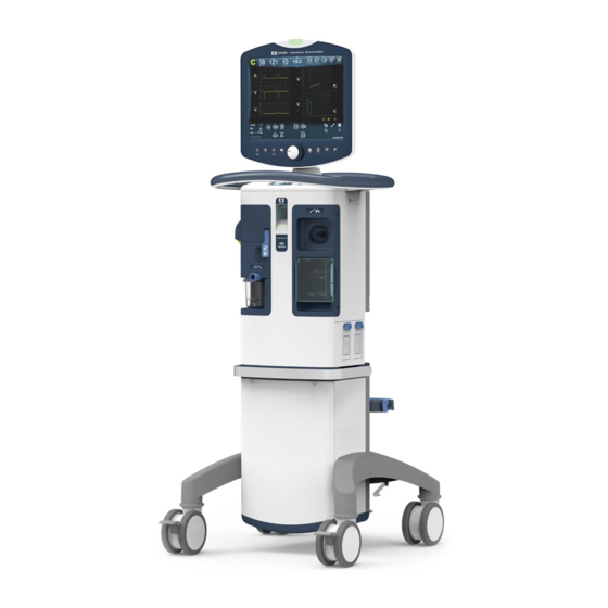
- Manuals
- Brands
- Medtronic Manuals
- Fan
- PURITAN BENNETT 980
- Installation reference manual
-
Contents
Table of Contents -
Bookmarks
Quick Links
EXHALATION FILTER ADAPTER
PURITAN BENNETT™ 980 VENTILATOR
INSTALLATION & REFERENCE GUIDE –
ADAPTER HAS NOT BEEN CLEARED BY US FDA
1
|For COVID-19 Response for Medtronic Customer & Hospital Only. PB980 Exhalation Filter Adapter Plate and Adapter have not been
cleared by US FDA | RE00262677 | Rev. B
Related Manuals for Medtronic PURITAN BENNETT 980
Summary of Contents for Medtronic PURITAN BENNETT 980
-
Page 1
INSTALLATION & REFERENCE GUIDE – ADAPTER HAS NOT BEEN CLEARED BY US FDA |For COVID-19 Response for Medtronic Customer & Hospital Only. PB980 Exhalation Filter Adapter Plate and Adapter have not been cleared by US FDA | RE00262677 | Rev. B… -
Page 2: Table Of Contents
CLEANING THE PB980 EXHALATION FILTER ADAPTER …………….12 APPENDIX A. PERFORMING FLOW SENSOR CALIBRATION, AND SST …………. 14 | For COVID-19 Response for Medtronic Customer & Hospital Only. PB980 Exhalation Filter Adapter Plate and Adapter have not been cleared by US FDA | RE00262677 | Rev. B…
-
Page 3: Preface
THE PB980 EXHALATION FILTER ADAPTER’ on Page 10 of this guide. | For COVID-19 Response for Medtronic Customer & Hospital Only. PB980 Exhalation Filter Adapter Plate and Adapter have not been cleared by US FDA | RE00262677 | Rev. B…
-
Page 4
This feature may only be used in the event of a PB980 Pediatric-Adult Exhalation Filter not being available due to the unforeseen demand caused by COVID-19 pandemic. | For COVID-19 Response for Medtronic Customer & Hospital Only. PB980 Exhalation Filter Adapter Plate and Adapter have not been cleared by US FDA | RE00262677 | Rev. B… -
Page 5
INSTALLING THE PB980 EXHALATION FILTER ADAPTER PLATE AND ADAPTER | For COVID-19 Response for Medtronic Customer & Hospital Only. PB980 Exhalation Filter Adapter Plate and Adapter have not been cleared by US FDA | RE00262677 | Rev. B… -
Page 6: Preparing The Pb980 Exhalation Filter Adapter Plate And Adapter For Installation
Dry Adapter Plate and Adapter per current site Sterilization Procedures. | For COVID-19 Response for Medtronic Customer & Hospital Only. PB980 Exhalation Filter Adapter Plate and Adapter have not been cleared by US FDA | RE00262677 | Rev. B…
-
Page 7: Installing The Pb980 Exhalation Filter Adapter Plate And Adapter For Use
PB980 Adapter Plate and Adapter are uninstalled. | For COVID-19 Response for Medtronic Customer & Hospital Only. PB980 Exhalation Filter Adapter Plate and Adapter have not been cleared by US FDA | RE00262677 | Rev. B…
-
Page 8
PB980 Exhalation Adapter Plate. Recommended hand-tightening with 5/64 Hex Driver. | For COVID-19 Response for Medtronic Customer & Hospital Only. PB980 Exhalation Filter Adapter Plate and Adapter have not been cleared by US FDA | RE00262677 | Rev. B… -
Page 9
SST on the PB980 Ventilator, following instructions provided in Appendix A (page 13). | For COVID-19 Response for Medtronic Customer & Hospital Only. PB980 Exhalation Filter Adapter Plate and Adapter have not been cleared by US FDA | RE00262677 | Rev. B… -
Page 10
USING PB980 VENTILATOR WITH THE PB980 EXHALATION FILTER ADAPTER | For COVID-19 Response for Medtronic Customer & Hospital Only. PB980 Exhalation Filter Adapter Plate and Adapter have not been cleared by US FDA | RE00262677 | Rev. B… -
Page 11: Filter Installation With Pb980 Exhalation Filter Adapter
Note: More frequent inspections of the filters are needed to check for condensate and increased filter resistance. | For COVID-19 Response for Medtronic Customer & Hospital Only. PB980 Exhalation Filter Adapter Plate and Adapter have not been cleared by US FDA | RE00262677 | Rev. B…
-
Page 12: Cleaning The Pb980 Exhalation Filter Adapter
Local support can be obtained by Medtronic staff through your normal communication channels. © 2020 Medtronic. All rights reserved. Medtronic, Medtronic logo and Further, Together are trademarks of Medtronic. Agile P/N : RE00262677 | For COVID-19 Response for Medtronic Customer & Hospital Only. PB980 Exhalation Filter Adapter Plate and Adapter have not been…
-
Page 13
APPENDIX A. PERFORMING FLOW SENSOR CALIBRATION, AND SST ON THE PB980 | For COVID-19 Response for Medtronic Customer & Hospital Only. PB980 Exhalation Filter Adapter Plate and Adapter have not been cleared by US FDA | RE00262677 | Rev. B… -
Page 14: Appendix A. Performing Flow Sensor Calibration, And Sst
1. Put the PB980 into Service Mode by following the guidance in the Puritan Bennett 980 Series Ventilator Operator’s Manual below: | For COVID-19 Response for Medtronic Customer & Hospital Only. PB980 Exhalation Filter Adapter Plate and Adapter have not been cleared by US FDA | RE00262677 | Rev. B…
-
Page 15
| For COVID-19 Response for Medtronic Customer & Hospital Only. PB980 Exhalation Filter Adapter Plate and Adapter have not been cleared by US FDA | RE00262677 | Rev. B… -
Page 16
2. Next, perform Flow Sensor Calibration as defined below: | For COVID-19 Response for Medtronic Customer & Hospital Only. PB980 Exhalation Filter Adapter Plate and Adapter have not been cleared by US FDA | RE00262677 | Rev. B… -
Page 17
SHORT SELF-TEST (SST) 3. Perform SST as defined below: | For COVID-19 Response for Medtronic Customer & Hospital Only. PB980 Exhalation Filter Adapter Plate and Adapter have not been cleared by US FDA | RE00262677 | Rev. B… -
Page 18
NOTE: All screenshots taken for Appendix A were from either (P/N: PT00102829A00) or (P/N: PT00101843A00) | For COVID-19 Response for Medtronic Customer & Hospital Only. PB980 Exhalation Filter Adapter Plate and Adapter have not been cleared by US FDA | RE00262677 | Rev. B…