Читал жалобы, что Radioddity GD-77 при работе в PMR диапазоне серет в соседние каналы.
Поэкспериментировал.
Подопытные:
1. Radioddity GD-77 запрограммированы PMR каналы (ширина полосы 12,5 кГц)
2. ZASTONE ZT-V9 приёмник прямого преобразования (тот же Баофенг пятый, только в другой обёртке)
Запрограммировал 8 каналов PMR с шириной полосы Narrow (узкая) и
Запрограммировал 8 каналов PMR с шириной полосы Wide (широкая)
3. Детская игрушка Motorola T4502 приёмник гетеродин. Ширина полосы никак не меняется, изначально узкая, заточена специально под PMR
_________________________
Передача с GD-77 на 4 канале PMR
Приём ZASTONE ZT-V9 на каналах с шириной полосы Narrow (узкая)
4 канал — чистый приём
3 и 5 каналы — короткие пшики в момент начала и конца передачи
1,2 и 6,7,8 каналы — тишина
__________________________
Передача с GD-77 на 4 канале PMR
Приём ZASTONE ZT-V9 на каналах с шириной полосы Wide (широкая)
3,4,5 канал — чистый приём
2 и 6 каналы — короткие пшики в момент начала и конца передачи
1 и 7,8 каналы — тишина
___________________________
Передача с GD-77 на 4 канале PMR
Приём Детская игрушка Motorola T4502
4 канал — чистый приём
1,2,3 и 5,6,7,8 каналы — тишина
___________________________
Передача ZASTONE ZT-V9 на 4 канале PMR с шириной полосы Narrow (узкая)
Приём Radioddity GD-77
4 канал — чистый приём
1,2,3 и 5,6,7,8 каналы — тишина
___________________________
Передача ZASTONE ZT-V9 на 4 канале PMR с шириной полосы Wide (широкая)
Приём Radioddity GD-77
4 канал — чистый приём
1,2,3 и 5,6,7,8 каналы — тишина
___________________________
Передача Детская игрушка Motorola T4502 на 4 канале PMR
Приём Radioddity GD-77
4 канал — чистый приём
1,2,3 и 5,6,7,8 каналы — тишина
___________________________
Передача Детская игрушка Motorola T4502 на 4 канале PMR
Приём ZASTONE ZT-V9 на каналах с шириной полосы Narrow (узкая)
4 канал — чистый приём
1,2,3 и 5,6,7,8 каналы — тишина
___________________________
Передача Детская игрушка Motorola T4502 на 4 канале PMR
Приём ZASTONE ZT-V9 на каналах с шириной полосы Wide (широкая)
4 канал — чистый приём
3 и 5 каналы — искажённый приём, если в Motorola T4502 громко говорить или дуть в микрофон
1,2 и 6,7,8 каналы — тишина
___________________________
Так что, всё дело — чем принимать.
Если Принимающая станция с приёмником прямого преобразования (не гетеродин), да ещё не правильно настроена (широкая полоса) тогда, да — всё плохо.
А вот Radioddity GD-77 — опять маладца)))
С соседних каналов ничего не хапает, даже если там идёт передача широкой полосой.
Эта информация предназначена в первую очередь для любителей поковыряться в своей GD-77. В любом случае пользователь принимает на себя всю ответственность и риск использования информации ниже и предоставленных здесь инструментов.
Radioddity GD-77 становится очень популярным двухдиапазонным DMR-трансивером начального уровня для использования радиолюбителями. В этом поле, если возникает проблема с оборудованием, пользователь вернет радио своему поставщику для ремонта. Низкая стоимость станции часто означает, что ремонт обычно невозможен, поэтому замена вместо ремонта является наиболее рентабельной стратегией.
Мы часто предпочитаем ремонтировать собственное радиооборудование, и у нас есть время экспериментировать, настраивать оборудование, пока оно не будет «таким как надо» для наших нужд. Проект по адаптации GD-77 возник из этой философии. Единственная проблема заключалась в том, что не было никаких инструментов, информации или ссылок, которые позволили бы поддерживать GD-77. Увидев необходимость в этой информации, Роджер VK3KYY, Colin G4EML и Jason VK7ZJA поместили GD-77 под микроскоп, чтобы получить необходимые инструменты для настройки и поддержки GD-77.
Radioddity имеет свой собственный процесс настройки для GD-77, что упоминается в документах FCC по сертификации, но это скрыто от широкой общественности, чтобы не работать в ущерб для компании. Поскольку Radioddity не имеет сервисного центра ремонта, публикация этой информации не лишит Radioddity дохода. Фактически, доступность этой информации может повысить привлекательность GD-77 для сообщества радиолюбителей и даже увеличить продажи, подобно тому, как MD380 Toolz должен был вызвать взрыв продаж для TYT.
Ожидается, что в результате этого проекта в конечном итоге будет создан автономный инструмент настройки программного обеспечения для GD-77. В настоящее время проект корректировки GD-77 еще не готов перейти на этот этап, поскольку некоторые данные должны быть уточнены и лучше расшифрованы для понимания. Как только это будет сделано, инструменты регулировки смогут быть полностью опубликован. Однако на данный момент большая часть базовой информации и инструментов все здесь, но представлена таким образом, что они довольно «сырая» и нуждается в небольшом опыте общения с техническими средствами, чтобы иметь возможность использовать их.
ПРЕДУПРЕЖДЕНИЕ. Программное обеспечение Flash Manager от GD-77 — инструмент очень низкого уровня, который может нанести серьезный и безвозвратный ущерб вашему радио. Неизбирательное использование может испортить как программное обеспечение, так и аппаратное обеспечение вашего радио. Удостоверьтесь, что вы точно и четко понимаете, что вы делаете.
Ссылки для скачивания:
Загрузите Flash-менеджер GD-77 здесь (77kb)
Загрузите файл поддержки DLL здесь; он должен находиться в том же каталоге, что и исполняемый файл Flash Manager. (96 kb)
Если вам нужен хороший шестнадцатеричный редактор, загрузите HxD на ваш предпочтительный язык здесь (около 860kb)
В GD-77 имеется четыре типа памяти:
1 ) EEPROM 64kbyte: здесь хранится половина кода.
2 ) Внешняя флэш-память 1 Мбайт: другая половина кода, идентификаторы DMR, написанные ActiveClient.exe, данные корректировки RF и даже символьные данные экрана тоже хранятся здесь.
3 ) Внутренняя флэш-память MCU емкостью 512 кбайт: здесь находится радиопрограмма.
4 ) MCU RAM RAM внутренний 128 кбайт: используется MCU для собственного внутреннего использования.
Диспетчер Flash GD-77 работает с внешней флэш-памятью. Все 1 мегабайт (8 Мбит) этой флэш-памяти читаются и записываются с помощью этого инструмента. Таким образом, он может редактировать половину исходного кода или идентификаторов DMR, хотя для их редактирования было бы проще использовать программное обеспечение CPS и ActiveClient.exe. Вы также можете редактировать источники экрана радио, если сможете узнать, как они закодированы в памяти, а затем перепроектировать источники.
Данные, представляющие особый интерес для нас, — это данные коррекции RF. Они находятся во флэш-памяти по адресам 0x08F000 до 0x08F0DF. Если вы изучаете другие части флэш-памяти, вы также можете найти другие копии данных юстировки RF в других местах, но «активные» данные всегда равны 0x08F000-0x08F0DF. Наличие других копий этих данных юстировки RF весьма полезно, особенно если активные данные повреждены. Подробнее об этом позже.
Первый шаг должен состоять в том, чтобы взять резервную копию всей флэш-памяти и сохранить ее в файле, на случай есть «что-то пойдет не так». Начните с отключения GD-77, подключите кабель программирования и включите GD-77, удерживая при этом следующую комбинацию клавиш: синяя боковая клавиша, зеленая кнопка меню и * клавиша (символ блокировки). Радио включится обычно без каких-либо других необычных видимых признаков.
Запустите Flash Administrator и внимательно обратите внимание на предупреждающее сообщение и нажмите «Да», чтобы продолжить. Введите начальный адрес (шестнадцатеричный) как 0 и введите длину (шестнадцатеричный) как 100000, который представляет собой один и пять нулей. Нажмите «Читать». Теперь вы должны увидеть, что экран GD-77 отвечает «Memory Prog», а светодиод на верхней панели мигает красным цветом и увеличивает процентную полосу на вашем ПК. Прочитать всю память займет около пяти с половиной минут. Затем сохраните файл и добавьте расширение .bin.
Чтобы начать изменять параметры, см. Таблицу ниже, которая показывает, какой байт (или бит) используется в каждом направлении во флэш-памяти. При изменении этих значений вы должны помнить, что флэш-память не похожа на EEPROM, вы не можете просто перезаписать данные. Данные, которые сначала меняются, должны быть удалены. Флэш-память может быть удалена в блоках по 4, 32 или 64 Кбайт. Прошивка GD-77 выполняет стирание блока размером в 64 кбайта для этой области флэш-памяти, а это означает, что если вы хотите изменить только один байт, флеш-память стирает этот блок объемом 64 Кбайт, и вам придется переписать эту сумму в 64 Кбайт. Имея это в виду, ваш первый шаг — прочитать блок данных размером 64 килобайта, содержащий данные юстировки RF.
Как указано выше, переведите GD-77 в специальный режим чтения / записи памяти с помощью синей боковой кнопки + зеленой кнопки меню + * (блокировка), нажатой при включении радио. Начните читать по адресу 80000 (hex) и прочитайте в байтах 10000 (hex). Сохраните этот блок данных в файл, если хотите. Прокрутите вниз до адреса 8F000, и вы увидите данные, начинающиеся с байтов A0 0F C0 12 A0 0F C0 12. Измените требуемый параметр, затем запишите данные, снова используя 80000 в качестве начального адреса и 10000 в качестве длины. Каждое чтение или запись для этого блока размером 64 килобайта займет около 25 секунд.
В Flash Manager есть некоторые практические функции, которые помогут вам манипулировать данными:
Ctrl-F — это функция поиска, в которой вы можете искать данные с текущей позиции курсора вперед. Вы можете искать шестнадцатеричные или ASCII-строки. F3 найдет следующее событие.
Ctrl-G перейдет на адрес, указанный в шестнадцатеричном формате, который может сэкономить много прокрутки в больших объемах экранов памяти.
СЕРЬЕЗНОЕ ПРЕДУПРЕЖДЕНИЕ : Небрежное изменение некоторых параметров может быть опасным для вашего радио. Например, установка выходной мощности радиочастоты на значительно более высокий уровень, чем тот, который уже откалиброван для вашего отдельного радиоприемника, вполне может дать увеличенный выход RF, но также значительно увеличит риск повреждения радио. Изменение параметров I & Q DMR определенно приведет к повреждению вашего сигнала, переданного DMR.
ИСПОЛЬЗОВАНИЕ ЭТОЙ ИНФОРМАЦИИ И ИНСТРУМЕНТОВ, ПРЕДОСТАВЛЯЕМЫХ НА САЙТЕ — ВАШ СОБСТВЕННЫЙ РИСК.
| Адрес во флэш-памяти | Типичное значение | использование | примечания |
| СВЧ-РАЗДЕЛ | |||
| 8F000 | A0 | UHF-приемник выигрывает все режимы, младший байт | Наименьшее значение = большее усиление |
| 8F001 | 0F | Приемник УВЧ получает все режимы, самый старший байт. | Нижнее значение = больше коэффициента усиления. Совет. Установите значение 07, чтобы улучшить чувствительность приглушения на 1-8 дБ (варьируется от радио к радио). Дальнейшие улучшения не наблюдались ниже. |
| 8F002 | C0 | Неизвестно, вы должны настроить это значение для работы УВЧ-передатчика | |
| 8F003 | 12 | Неизвестно, вы должны настроить это значение для работы УВЧ-передатчика | |
| 8F004 | A0 | Неизвестно, вы должны настроить это значение для работы УВЧ-передатчика | |
| 8F005 | 0F | Неизвестно, вы должны настроить это значение для работы УВЧ-передатчика | |
| 8F006 | C0 | Неизвестно, вы должны настроить это значение для работы УВЧ-передатчика | |
| 8F007 | 12 | Неизвестно, вы должны настроить это значение для работы УВЧ-передатчика | |
| 8F008 | E8 | Слово ЦАП для частотного осциллятора частоты в УВЧ, тонкая настройка.Сначала отрегулируйте это значение | Сложное взаимодействие между этими двумя байтами |
| 8F009 | 03 | Слово ЦАП для генератора опорных частот в УВЧ, настройка. Отрегулируйте это значение, только если вы не можете получить достаточный диапазон регулировки, отрегулировав значение только по адресу 8F008. | Сложное взаимодействие между этими двумя байтами |
| 8F00A | E9 | неизвестный | |
| 8F00B | 83 | Низкая конфигурация выходной мощности ВЧ, частота СВЧ 400 МГц | 00 = нижняя мощность, FF = большая мощность |
| 8F00C | C6 | Конфигурация высокочастотной выходной мощности, частота UHF 400 МГц | ПРЕДУПРЕЖДЕНИЕ: чрезмерно высокие настройки сжигают электронику |
| 8F00D | 82 | Низкая настройка выходной мощности радиочастоты, частота УВЧ 405 МГц | Совет: значение меньше 40 hex. Он дает примерно 30 мВт выходного сигнала, значение 20 не дает детектируемого выхода. |
| 8F00E | C5 | Конфигурация высокочастотной выходной мощности, частота UHF 405 МГц | ПРЕДУПРЕЖДЕНИЕ: чрезмерно высокие настройки сжигают электронику |
| 8F00F | 81 | Регулировка низкой выходной мощности радиочастоты, частота UHF 410 МГц | |
| 8F010 | C6 | Конфигурация высокочастотной выходной мощности, СВЧ-частота 410 МГц | ПРЕДУПРЕЖДЕНИЕ: чрезмерно высокие настройки сжигают электронику |
| 8F011 | 81 | Конфигурация низкочастотной выходной мощности, частота UHF 415 МГц | |
| 8F012 | C7 | Конфигурация высокочастотной выходной мощности, частота УВЧ 415 МГц | ПРЕДУПРЕЖДЕНИЕ: чрезмерно высокие настройки сжигают электронику |
| 8F013 | 80 | Регулировка низкой выходной мощности радиочастоты, частота UHF 420 МГц | |
| 8F014 | C9 | Конфигурация высокочастотной мощности, UHF-частота 420 МГц | ПРЕДУПРЕЖДЕНИЕ: чрезмерно высокие настройки сжигают электронику |
| 8F015 | 80 | Конфигурация низкочастотной мощности, UHF-частота 425 МГц | |
| 8F016 | Калифорния | Конфигурация высокочастотной выходной мощности, частота UHF 425 МГц | ПРЕДУПРЕЖДЕНИЕ: чрезмерно высокие настройки сжигают электронику |
| 8F017 | 81 | Конфигурация низкочастотной мощности, UHF-частота 430 МГц | |
| 8F018 | CB | Конфигурация высокочастотной выходной мощности, частота УВЧ 430 МГц | ПРЕДУПРЕЖДЕНИЕ: чрезмерно высокие настройки сжигают электронику |
| 8F019 | 81 | Конфигурация низкочастотной выходной мощности, частота UHF 435 МГц | |
| 8F01A | CB | Конфигурация высокочастотной мощности, частота UHF 435 МГц | ПРЕДУПРЕЖДЕНИЕ: чрезмерно высокие настройки сжигают электронику |
| 8F01B | 81 | Низкая конфигурация выходной мощности ВЧ, частота СВЧ 440 МГц | |
| 8F01C | C8 | Конфигурация высокочастотной мощности, частота радиочастот 440 МГц | ПРЕДУПРЕЖДЕНИЕ: чрезмерно высокие настройки сжигают электронику |
| 8F01D | 81 | Конфигурация низкочастотной мощности, UHF-частота 445 МГц | |
| 8F01E | C6 | Конфигурация высокочастотной выходной мощности, частота UHF 445 МГц | ПРЕДУПРЕЖДЕНИЕ: чрезмерно высокие настройки сжигают электронику |
| 8F01F | 81 | Конфигурация низкочастотной выходной мощности, частота UHF 450 МГц | |
| 8F020 | C5 | Конфигурация высокочастотной выходной мощности, частота УВЧ 450 МГц | ПРЕДУПРЕЖДЕНИЕ: чрезмерно высокие настройки сжигают электронику |
| 8F021 | 81 | Низкая установка выходной мощности радиочастоты, частота UHF 455 МГц | |
| 8F022 | C5 | Конфигурация высокочастотной выходной мощности, частота UHF 455 МГц | ПРЕДУПРЕЖДЕНИЕ: чрезмерно высокие настройки сжигают электронику |
| 8F023 | 7F | Конфигурация низкочастотной мощности, UHF-частота 460 МГц | |
| 8F024 | C4 | Конфигурация высокочастотной выходной мощности, частота УВЧ 460 МГц | ПРЕДУПРЕЖДЕНИЕ: чрезмерно высокие настройки сжигают электронику |
| 8F025 | 7E | Конфигурация низкочастотной мощности, частота UHF 465 МГц | |
| 8F026 | C6 | Конфигурация высокочастотной выходной мощности, UHF-частота 465 МГц | ПРЕДУПРЕЖДЕНИЕ: чрезмерно высокие настройки сжигают электронику |
| 8F027 | 7D | Конфигурация низкочастотной мощности, UHF-частота 470 МГц | |
| 8F028 | C6 | Конфигурация высокочастотной выходной мощности, частота УВЧ 470 МГц | ПРЕДУПРЕЖДЕНИЕ: чрезмерно высокие настройки сжигают электронику |
| 8F029 | 7D | Регулировка низкой выходной мощности радиочастоты, частота UHF 475 МГц | |
| 8F02A | C6 | Конфигурация высокочастотной мощности, UHF-частота 475 МГц | ПРЕДУПРЕЖДЕНИЕ: чрезмерно высокие настройки сжигают электронику |
| 8F02B | 3D | неизвестный | |
| 8F02C | 3B | неизвестный | |
| 8F02D | 3A | неизвестный | |
| 8F02E | 38 | неизвестный | |
| 8F02F | 37 | неизвестный | |
| 8F030 | 36 | неизвестный | |
| 8F031 | 35 | неизвестный | |
| 8F032 | A9 | неизвестный | |
| 8F033 | 1D | неизвестный | |
| 8F034 | 0D | неизвестный | |
| 8F035 | 0D | неизвестный | |
| 8F036 | 11 | неизвестный | |
| 8F037 | 11 | неизвестный | |
| 8F038 | 0B | неизвестный | |
| 8F039 | 0B | неизвестный | |
| 8F03A | 0F | неизвестный | |
| 8F03B | 00 | неизвестный | |
| 8F03C | 00 | неизвестный | |
| 8F03D | 00 | неизвестный | |
| 8F03E | 00 | неизвестный | |
| 8F03F | 18 | неизвестный | |
| 8F040 | шестнадцать | неизвестный | |
| 8F041 | 14 | неизвестный | |
| 8F042 | 13 | неизвестный | |
| 8F043 | шестнадцать | неизвестный | |
| 8F044 | 14 | неизвестный | |
| 8F045 | 15 | неизвестный | |
| 8F046 | 12 | Отключить усиление чувствительности.Нижнее значение = более чувствительное молчание. Не превышайте значение 08. | |
| 8F047 | 3E | UHF Отключить звук, широкополосный, закрыть | Более высокое значение = более низкий уровень радиочастоты / более чувствительный. NB: строгие и нормальные значения немного взаимодействуют |
| 8F048 | 3C | UHF Отключить звук, широкополосный, открытый | |
| 8F049 | 3E | неизвестный | |
| 8F04A | 3A | неизвестный | |
| 8F04B | 53 | UHF Нормальная немая, широкополосная, закрытая | |
| 8F04C | 51 | UHF Нормальная тишина, широкополосная связь, открытая | |
| 8F04D | 34 | UHF Отключить строгий, узкополосный, закрыть | Более высокое значение = более низкий уровень радиочастоты / более чувствительный. NB: строгие и нормальные значения немного взаимодействуют |
| 8F04E | 32 | UHF Отключить звук, узкополосный, открытый | |
| 8F04F | 34 | неизвестный | |
| 8F050 | 32 | неизвестный | |
| 8F051 | 53 | UHF нормальный звук, узкая полоса, закрытие | |
| 8F052 | 51 | UHF Отключить звук, узкая полоса, открыть | |
| 8F053 | 1С | Счетчик сигналов приема УВЧ, нижний | Предложение: оставить как есть |
| 8F054 | 20 | UHF приемный сигнальный счетчик, high-end | Совет: установите 60 для более реалистичной индикации RSSI. 1 бар = -113 дБм, 2 бара = -95 дБм, 3 бара = -80 дБм |
| 8F055 | 3C | UHF 405 МГц DMR TX I и Q баланс | Не настраивать |
| 8F056 | 3A | UHF 415 МГц DMR TX I и Q баланс | Не настраивать |
| 8F057 | 39 | UHF 425 МГц DMR TX I и Q баланс | Не настраивать |
| 8F058 | 38 | UHF 435 МГц DMR TX I и Q баланс | Не настраивать |
| 8F059 | 36 | UHF 445 МГц DMR TX I и Q баланс | Не настраивать |
| 8F05A | 35 | UHF 455 МГц DMR TX I и Q баланс | Не настраивать |
| 8F05B | 34 | UHF 465 МГц DMR TX I и Q баланс | Не настраивать |
| 8F05C | 33 | UHF 475 МГц DMR TX I и Q баланс | Не настраивать |
| 8F05D | 1D | UHF DMR получает громкость звука и звуковой сигнал (не регулируется независимо) | Более высокое значение = больше прибыли |
| 8F05E | 0F | Отклонение UHF TX DTMF | Более высокое значение = большее отклонение |
| 8F05F | 0D | UHF Tone Burst Deviation TX 1750Hz | Более высокое значение = большее отклонение |
| 8F060 | 11 | UHF отклонение TX CTCSS, широкополосный | Более высокое значение = большее отклонение |
| 8F061 | 11 | Отклонение UHF TX CTCSS, узкая полоса | Более высокое значение = большее отклонение |
| 8F062 | 0B | UHF-отклонение TX DCS, широкополосный | Более высокое значение = большее отклонение |
| 8F063 | 0B | Отклонение UHF TX DCS, узкая полоса | Более высокое значение = большее отклонение |
| 8F064 | 0F | Неизвестно, но не настроено: влияет на выходную мощность радиочастоты и модуляцию во всех режимах | Не настраивать |
| 8F065 | 0D | Неизвестно, но не настроено: влияет на выходную мощность радиочастоты и модуляцию во всех режимах | Не настраивать |
| 8F066 | 31 | Однократное аналоговое усиление микрофона УВЧ (широкополосное и узкополосное) не превышает 7F | Более высокое значение = больше прибыли |
| 8F067 | 05 | UHF получает целевое значение прибыли AGC | Более высокое значение = больше прибыли |
| 8F068 | 27 | Общее отклонение аналогового отклонения UHF (CTCSS, DCS, DTMF и голос), широкополосная, тонкая настройка | Более высокое значение = большее отклонение |
| 8F069 | 00 | Общее аналоговое отклонение UHF (CTCSS, DCS, DTMF и голос), толстая широкополосная регулировка. Нет необходимости настраивать более 00 | Более высокое значение = большее отклонение |
| 8F06A | 27 | Общее отклонение аналогового отклонения UHF (CTCSS, DCS, DTMF и голос), узкая полоса, тонкая настройка | Более высокое значение = большее отклонение |
| 8F06B | 00 | Общее аналоговое отклонение UHF (CTCSS, DCS, DTMF и голос), толстая настройка узкой полосы. Нет необходимости настраивать более 00 | Более высокое значение = большее отклонение |
| 8F06C | 0F | Аналог UHF получает только усиление звука. Допустимый диапазон от 00 до 0F. | 8F06C и 8F06D, чтобы получить общую величину усиления |
| 8F06D | 0D | Аналог UHF получает только усиление звука. Допустимый диапазон от 00 до 0F. | Более высокое значение = больше прибыли |
| 8F06E | 00 | неизвестный | |
| 8F06F | 00 | неизвестный | |
| Раздел VHF | |||
| 8F070 | 50 | предположительно, является усилением приемника УКВ, младшим значащим байтом | Наименьшее значение = большее усиление |
| 8F071 | 05 | предполагается, что это усиление приемника ОВЧ, наиболее значимого байта | Нижнее значение = больше коэффициента усиления. Совет. Установите значение 03, чтобы улучшить чувствительность приглушения на 1-8 дБ (варьируется от радиуса к радиусу). Дальнейшие улучшения не наблюдались ниже. |
| 8F072 | CC | Неизвестно, это значение должно быть установлено для работы передатчика ОВЧ | |
| 8F073 | 06 | Неизвестно, это значение должно быть установлено для работы передатчика ОВЧ | |
| 8F074 | 50 | Неизвестно, это значение должно быть установлено для работы передатчика ОВЧ | |
| 8F075 | 05 | Неизвестно, это значение должно быть установлено для работы передатчика ОВЧ | |
| 8F076 | CC | Неизвестно, это значение должно быть установлено для работы передатчика ОВЧ | |
| 8F077 | 06 | Неизвестно, это значение должно быть установлено для работы передатчика ОВЧ | |
| 8F078 | EB | Слово ЦАП для частотного осциллятора частоты в УКВ, тонкая настройка.Сначала отрегулируйте это значение | Сложное взаимодействие между этими двумя байтами |
| 8F079 | 03 | DAC для генератора опорных частот в УКВ, настройка. Отрегулируйте это значение, только если вы не можете получить достаточный диапазон регулировки, отрегулировав значение только по адресу 8F079. | Сложное взаимодействие между этими двумя байтами |
| 8F07A | EE | неизвестный | |
| 8F07B | 40 | Конфигурация низкочастотной мощности, частота VHF 136 МГц | 00 = нижняя мощность, FF = большая мощность |
| 8F07C | Британский клубный автомобиль | Конфигурация высокочастотной выходной мощности, частота ОВЧ 136 МГц | ПРЕДУПРЕЖДЕНИЕ: чрезмерно высокие настройки сжигают электронику |
| 8F07D | 41 | Регулировка низкой выходной мощности радиочастоты, частота УКВ 140 МГц | Совет: значение меньше 40 hex. Он дает примерно 125 мВт выходного сигнала, значение 20 не дает детектируемого выхода. |
| 8F07E | BD | Конфигурация высокочастотной выходной мощности, УКВ-частота 140 МГц | ПРЕДУПРЕЖДЕНИЕ: чрезмерно высокие настройки сжигают электронику |
| 8F07F | 4E | Регулировка низкой выходной мощности радиочастоты, частота ОВЧ 145 МГц | |
| 8F080 | SER | Конфигурация высокочастотной мощности, частота VHF 145 МГц | ПРЕДУПРЕЖДЕНИЕ: чрезмерно высокие настройки сжигают электронику |
| 8F081 | 55 | Регулировка низкой выходной мощности радиочастоты, частота УКВ 150 МГц | |
| 8F082 | B6 | Конфигурация высокочастотной выходной мощности, частота УКВ 150 МГц | ПРЕДУПРЕЖДЕНИЕ: чрезмерно высокие настройки сжигают электронику |
| 8F083 | 56 | Низкая установка мощности радиочастоты, частота УКВ 155 МГц | |
| 8F084 | B1 | Конфигурация высокочастотной выходной мощности, частота УКВ 155 МГц | ПРЕДУПРЕЖДЕНИЕ: чрезмерно высокие настройки сжигают электронику |
| 8F085 | 56 | Низкая настройка выходной мощности радиочастоты, частота радиочастоты на частоте 160 МГц | |
| 8F086 | B5 | Конфигурация высокочастотной выходной мощности, частотная частота 160 МГц | ПРЕДУПРЕЖДЕНИЕ: чрезмерно высокие настройки сжигают электронику |
| 8F087 | 59 | Низкая установка мощности радиочастоты, частота УКВ 165 МГц | |
| 8F088 | B8 | Конфигурация высокочастотной выходной мощности, частота ОВЧ 165 МГц | ПРЕДУПРЕЖДЕНИЕ: чрезмерно высокие настройки сжигают электронику |
| 8F089 | 5C | Регулировка низкой выходной мощности радиочастоты, частота УКВ 172 МГц | |
| 8F08A | B8 | Конфигурация высокочастотной выходной мощности, частота УКВ 172 МГц | ПРЕДУПРЕЖДЕНИЕ: чрезмерно высокие настройки сжигают электронику |
| 8F08B | FF | Не применяется | |
| 8F08C | FF | Не применяется | |
| 8F08D | FF | Не применяется | |
| 8F08E | FF | Не применяется | |
| 8F08F | FF | Не применяется | |
| 8F090 | FF | Не применяется | |
| 8F091 | FF | Не применяется | |
| 8F092 | FF | Не применяется | |
| 8F093 | FF | Не применяется | |
| 8F094 | FF | Не применяется | |
| 8F095 | FF | Не применяется | |
| 8F096 | FF | Не применяется | |
| 8F097 | FF | Не применяется | |
| 8F098 | FF | Не применяется | |
| 8F099 | FF | Не применяется | |
| 8F09A | FF | Не применяется | |
| 8F09B | 40 | неизвестный | |
| 8F09C | F0 | неизвестный | |
| 8F09D | 40 | неизвестный | |
| 8F09E | F0 | неизвестный | |
| 8F09F | 40 | неизвестный | |
| 8F090 | F0 | неизвестный | |
| 8F0A1 | FF | Не применяется | |
| 8F0A2 | FF | Не применяется | |
| 8F0A3 | 0F | неизвестный | , |
| 8F0A4 | 0F | неизвестный | |
| 8F0A5 | 0F | неизвестный | |
| 8F0A6 | 1В | неизвестный | |
| 8F0A7 | 1В | неизвестный | |
| 8F0A8 | 1В | неизвестный | |
| 8F0A9 | FF | Не применяется | |
| 8F0AA | FF | Не применяется | |
| 8F0AB | 00 | неизвестный | |
| 8F0AC | 00 | неизвестный | |
| 8F0AD | 00 | неизвестный | |
| 8F0AE | 00 | неизвестный | |
| 8F0AF | 1D | неизвестный | |
| 8F0B0 | 1D | неизвестный | |
| 8F0B1 | 1D | неизвестный | |
| 8F0B2 | 1С | неизвестный | |
| 8F0B3 | 1С | неизвестный | |
| 8F0B4 | 1С | неизвестный | |
| 8F0B5 | 1В | неизвестный | |
| 8F0B6 | 1В | Отключить усиление чувствительности.Нижнее значение = более чувствительное молчание. Не превышайте значение 08. | |
| 8F0B7 | 3E | VHF Отключить звук, широкополосный, закрыть | Более высокое значение = более низкий уровень радиочастоты / более чувствительный. NB: строгие и нормальные значения немного взаимодействуют |
| 8F0B8 | 3C | VHF Mute строгая, широкополосная, открытая | |
| 8F0B9 | 3D | неизвестный | |
| 8F0BA | 3A | неизвестный | |
| 8F0BB | 53 | VHF Нормальная тишина, широкополосная связь, закрытие | |
| 8F0BC | 51 | VHF Нормальная тишина, широкополосная, открытая | |
| 8F0BD | 34 | VHF Отключить звук, узкополосный, закрыть | Более высокое значение = более низкий уровень радиочастоты / более чувствительный. NB: строгие и нормальные значения немного взаимодействуют |
| 8F0BE | 32 | VHF Mute строгая, узкополосная, открытая | |
| 8F0BF | 34 | неизвестный | |
| 8F0C0 | 32 | неизвестный | |
| 8F0C1 | 53 | VHF Нормальная тишина, узкая полоса, закрытие | |
| 8F0C2 | 51 | VHF Нормальная тишина, узкая полоса, открытая | |
| 8F0C3 | 20 | Сигнальный счетчик получен VHF, нижний конец | Предложение: оставить как есть |
| 8F0C4 | 27 | Полученный сигнальный счетчик VHF, high-end | Совет. Настройте 5D, чтобы получить более реалистичную индикацию RSSI. 1 бар = -113 дБм, 2 бара = -95 дБм, 3 бара = -80 дБм |
| 8F0C5 | B1 | VHF 136 МГц DMR TX I и Q баланс | Не настраивать |
| 8F0C6 | AB | VHF 140 МГц DMR TX I и Q баланс | Не настраивать |
| 8F0C7 | A5 | VHF 145 МГц DMR TX I и Q баланс | Не настраивать |
| 8F0C8 | A0 | VHF 150 МГц DMR TX I и Q баланс | Не настраивать |
| 8F0C9 | 9В | VHF 155 МГц DMR TX I и Q баланс | Не настраивать |
| 8F0CA | 95 | VHF 160 МГц DMR TX I и Q баланс | Не настраивать |
| 8F0CB | 90 | VHF 165 МГц DMR TX I и Q баланс | Не настраивать |
| 8F0CC | 8E | VHF 172 МГц DMR TX I и Q баланс | Не настраивать |
| 8F0CD | 1D | VHF DMR получает усиление звука и подозрительный звуковой сигнал (не регулируется независимо) | Более высокое значение = больше прибыли |
| 8F0CE | 10 | DTMF отклонение VHF TX | Более высокое значение = большее отклонение |
| 8F0CF | 0D | VHF TX 1750 Гц отклонение от тангажа | Более высокое значение = большее отклонение |
| 8F0D0 | 11 | УКВ-отклонение TX CTCSS, широкополосная | Более высокое значение = большее отклонение |
| 8F0D1 | 11 | VHF отклонение TX CTCSS, узкая полоса | Более высокое значение = большее отклонение |
| 8F0D2 | 0B | УКВ-отклонение TX DCS, широкополосный | Более высокое значение = большее отклонение |
| 8F0D3 | 0B | VHF-отклонение TX DCS, узкая полоса | |
| 8F0D4 | 08 | Неизвестно, но не настроено: влияет на выходную мощность радиочастоты и модуляцию во всех режимах | Не настраивать |
| 8F0D5 | 0D | Неизвестно, но не настроено: влияет на выходную мощность радиочастоты и модуляцию во всех режимах | Не настраивать |
| 8F0D6 | 31 | Усиление микрофона только в аналоговой УКВ (широкополосной и узкой полосе) не превышает значение 7F | Более высокое значение = больше прибыли |
| 8F0D7 | 05 | VHF получает целевое значение прибыли AGC | Более высокое значение = больше прибыли |
| 8F0D8 | 27 | Общее отклонение аналогового отклонения VHF (CTCSS, DCS, DTMF и голос), широкополосная, тонкая настройка | Более высокое значение = большее отклонение |
| 8F0D9 | 00 | Аналоговое общее отклонение ОВЧ (CTCSS, DCS, DTMF и голос), грубая широкополосная регулировка. Нет необходимости настраивать более 00 | Более высокое значение = большее отклонение |
| 8F0DA | 27 | Общее отклонение аналогового отклонения VHF (CTCSS, DCS, DTMF и голос), узкая полоса, тонкая настройка | Более высокое значение = большее отклонение |
| 8F0DB | 00 | Общее аналоговое отклонение VHF (CTCSS, DCS, DTMF и голос), регулировка толщины узкой полосы.Нет необходимости настраивать более 00 | Более высокое значение = большее отклонение |
| 8F0DC | 0F | Аналоговая УКВ только получает усиление звука. Допустимый диапазон от 00 до 0F. | 8F0DC и 8F0DD, чтобы получить общую величину усиления |
| 8F0DD | 0F | Аналоговая УКВ только получает усиление звука. Допустимый диапазон от 00 до 0F. | Более высокое значение = больше прибыли |
| 8F0DE | 00 | неизвестный | |
| 8F0DF | 00 | неизвестный |
Если вы можете решить, какие параметры неизвестны, сообщите мне по электронной почте: vk7zja(at)gmail(dot)com
ВОССТАНОВЛЕНИЕ ДАННЫХ ПОСЛЕ СБРОСА ПАМЯТИ / ЗАВОДСКИХ УСТАНОВОК
Память и / или заводская перезагрузка GD-77 могут повредить информацию в блоке данных выравнивания RF по адресу 8F000 и выше. Типичные симптомы очень низкие или нет радиочастотного сигнала радио, либо в аналоговом режиме FM, либо в цифровом режиме DMR.
Ранее некоторые пользователи проходили это повреждение, переключившись на предыдущие версии прошивки, а затем снова выполняли сброс и обновление памяти. Это может работать или не работать для новых версий прошивки, отчеты о успехах варьируются от пользователя к пользователю, и я подозреваю, что он может иметь какое-то отношение к ранее существовавшим условиям во флэш-памяти.
Здесь мы описываем метод восстановления, который является как более надежным, так и более быстрым, чем предыдущий метод восстановления с восстановлением-сбросом обновления.
Как всегда, используйте эти инструменты и информацию с осторожностью, так как небрежное использование может нанести серьезный ущерб.
Шаг 1: Загрузите Flash Manager, поддерживайте DLL-файл, и если у вас еще нет шестнадцатеричного редактора, загрузите и установите HxD. Ссылки на скачивание указаны выше.
Шаг 2: Выключите поврежденный GD-77, подключите кабель программирования к радио и ПК. Не включайте GD-77.
Шаг 3: При включении GD-77 нажмите и удерживайте синюю боковую клавишу, зеленую клавишу меню (стрелка вверх) и клавишу * / lock (чуть ниже кнопки со стрелкой вправо). Радио включится нормально.
Шаг 4. Запустите Flash Administrator.
Шаг 5: Прочитайте всю память. Задайте начальный адрес (шестнадцатеричный) равным 0 и установите Longitude (шестнадцатеричный) на 100000, то есть один за ним следует пять нулей. Нажмите кнопку «Читать» и подождите около 5-6 минут для завершения чтения.
Шаг 6: Экспорт прочитанных данных в файл с помощью кнопки «Сохранить файл». Назовите файл как corruptGD77.bin. В Windows файл должен иметь размер 1,0 Мбайт.
Шаг 7: Запустите HxD или ваш любимый шестнадцатеричный редактор. Откройте файл, который вы только что сохранили в Flash Manager.
Шаг 8: Теперь найдите другие копии данных выравнивания RF, которые должны быть скрыты в других местах дампа флэш-памяти. Мы полагаемся на то, что некоторые RF-данные выравнивания никогда не меняются с радио на радио. Один из этих элементов данных отображается как строка ASCII SQ4242 (верхний регистр / верхний регистр SQ). Сделайте поиск с самого начала, ища строку ASCII SQ4242
Шаг 9: После того как вы нашли это событие, просмотрите данные вокруг вас. Примерно 75 (десятичных) байтов перед этой последовательностью SQ4242 должен быть набор повторяющихся байтов A0 0F C0 12 A0 0F C0 12. Если вы найдете это, то очень вероятно, что вы нашли действительную и не поврежденную копию ваших радиочастотных радиочастот выравнивания. Если вы не нашли этого, продолжайте поиск, пока не найдете правильные данные выравнивания RF. Общий адрес для поиска таких данных обычно составляет от 50100 до 501DF (шестнадцатеричный)
Шаг 10: С начала последовательности байтов A0 0F C0 12 A0 0F C0 12 скопируйте блок из 224 байт. Затем, если вы найдете достоверные данные выравнивания, начиная с адреса 50100, скопируйте данные с адреса 50100 в 501DF и вставьте эти данные в адрес, начинающийся с 8F000. Вы можете выделить, скопировать и вставить HxD, что очень полезно.
Шаг 11: После того как вы удовлетворены тем, что у вас есть действительные данные выравнивания RF, скопированные для адреса 8F000 — 8F0DF, сохраните файл на диск, называя его как repairedGD77.bin. Опять же, файл должен отображаться размером 1,0 МБ в Windows.
Шаг 12: Вернитесь в Flash Manager, используйте кнопку «Открыть файл», чтобы загрузить файл repairedGD77.bin. Прокрутите вниз или используйте функцию Ctrl-G, чтобы перейти непосредственно к адресу 8F000 и подтвердить, что есть действительные данные выравнивания RF. Как уже упоминалось выше, он начинается с байтов A0 0F C0 12 A0 0F C0 12. Если он там не появляется, что-то не получилось, и вы должны вернуться к шагу 7 выше и повторите попытку.
Шаг 13: Выключите GD-77 и включите его снова с помощью специальной последовательности включения питания, как и на шаге 3.
Шаг 14: Настало время написать правильные данные выравнивания RF в радио. Нет необходимости писать весь флэш-контент, но нам нужно написать хотя бы блок из 64kbytes, чтобы это работало. Введите начальный адрес (шестнадцатеричный) 80000 — это восемь, за которым следуют четыре нуля, и введите длину (шестнадцатеричный) как 10000 — это один за ним, за которым следуют четыре нуля. Нажмите «Запись» и подождите около 25 секунд, чтобы запись завершилась.
Шаг 15: Выключите GD-77, удалите кабель программирования, включите его и выполните тест. Теперь ваш GD-77 должен работать номинально.
Не рекомендуется использовать типичные значения в приведенной выше таблице для восстановления нового блока данных выравнивания RF с нуля, если он не используется в качестве последнего средства. Причина этого в том, что некоторые параметры очень важны, особенно для настройки частоты и значений I & Q DMR. Всегда лучше искать копии данных выравнивания RF, которые являются специфическими и уникальными для вашего радио. Типичные значения приведены только в качестве руководства и дают некоторый контекст потенциальным корректировкам, которые вы, возможно, пожелаете сделать.
Версия 1.4
© Джейсон Рейли, 2018
Ссылка на эту страницу:

![]()
OpenGD77 User Guide
For OpenGD77 / OpenGD77S / OpenDM1801* / OpenDM1801A* / OpenRD5R / MD-9600 (RT-90) / MD-UV380 (RT-3S) / MD-UV390
For the latest information and discussions, please refer to the development and community forum at https://opengd77.com
The firmware is also NOT compatible with the new 2022 version of the Baofeng DM-1801, or the new DM-1801A
Table of Contents
- OpenGD77 / OpenGD77S / OpenDM1801* / OpenDM1801A* / OpenRD5R / MD-9600 (RT-90) / MD-UV380 (RT-3S) User Guide
- Introduction
- Download links and other resources
- Installation
- Transferring data to Radio
- Codeplug compatibility
- Variations between different supported radios
- Main screens (VFO and Channel screens)
- Changing between VFO and Channel
- Changing Timeslot in DMR mode
- Changing bandwidth in FM mode
- Controlling Tx power
- Signal strength bar graph
- Channel screen specific functionality
- Changing channels within the current zone
- Changing zones
- Displaying the channel Frequency
- Displaying FM specific channel information
- Reverse repeater operation
- Channel Quick Menu
- Copying a channel to VFO
- Read the VFO into the current channel
- Filter
- VFO Quick Menu
- VFO selection A or B
- Exchange the TX and RX frequencies
- Copy the RX frequency to the TX frequency
- Copy TX frequency to the RX frequency
- Filter
- VFO to New Channel
- Tone Scan for CTCSS or DCS tone in FM
- DMR specific functionality (VFO and Channel screens)
- Timeslot selection
- DMR ID callsign and name display
- Talker Alias display
- Talkgroup selection from the Rx Group list
- Assignment of Timeslot to Digital Contact TalkGroup
- TalkGroup displayed in inverse video
- Manual TalkGroup number entry
- Private Call number entry
- Digital Contact selection
- Station DMR ID number entry
- FM specific functionality (VFO and Channel screens)
- FM and FM Narrow
- CTCSS Tone or DCS Code
- Squelch
- 1750Hz Tone for repeater operation
- DTMF tone transmission
- DTMF sequence entry and transmission
- VFO specific functionality
- Frequency change up/down step
- Numerical frequency entry
- To adjust the TX frequency, independent of the RX frequency
- Spectrum sweep scan
- VFO Dual Watch
- Monitor mode
- Transmitting
- Timeout warning beep
- TOT
- Scanning
- Channel scanning
- VFO scanning
- Other screens
- Lock screen
- Text entry
- The control keys and buttons
- The Menu System
- QuickKeys
- Main Menu
-
Zone
-
RSSI
-
Radio info
- Battery voltage and percentage
- Time clock
- Date screen
- Location screen
- CPU Temperature
- Battery voltage history
-
Contacts
- DMR Contacts
- FM DTMF Contacts
- New Contact
-
Last Heard
-
Firmware Info and credits
-
Options — contains the 4 following options screens
- Language
- General Options
- Key long
- Key rpt
- Hotspot
- Temp Cal
- Batt Cal
- Time Cal
- Eco Level
- Suspend
- Safe Pwr-On
- Auto Pwr-Off
- APO with RF
- Satellite follow mode
- Radio Options
- Band Limits
- Filter time
- Scan delay
- Scan dwell
- Scan mode
- Scan on Boot
- Squelch UHF
- Squelch 220
- Squelch VHF
- PTT Latch
- TA Tx
- Allow PC
- User Power
- DMR crc
- Display Options
- Brightness
- Min Bright
- Contrast
- Display mode
- Timeout
- Colour mode
- Order
- Contact
- Battery units
- Info
- LEDs
- Timezone
- Time
- Sound Options
- Timeout beep
- Beep volume
- DMR Beep
- RX Beep
- Talker
- DMR mic
- FM mic
- VOX threshold
- VOX Tail
- Prompt
- DMR Rx AGC
- Click suppr
- Radio Calibration
-
Channel Details
- Channel name
- RX
- TX
- Mode
- DMR ID
- Color Code
- Timeslot
- Tx/RX Grp
- Tx CTCSS or DCS
- Rx CTCSS or DCS
- Bandwidth
- Step
- TOT
- Rx Only
- Zone Skip
- All Skip
- VOX
- Channel Power
- Channel squelch
- Channel beep
- Channel Eco mode
- Accepting and saving the changes to the channel
-
Satellite Screen
-
GPS Screen
-
- Making and receiving DMR Private Calls
- To make a Private Call
- To Receive a Private Call
- Hotspot mode
- Resetting the Settings
- GD-77S operation
- GD77S Channel / TG mode
- GD77S Scan mode
- GD77S Timeslot mode
- GD77S Color Code mode
- GD77S DMR Filter mode
- GD77S Zone mode
- GD77S Power mode
- MD-9600|RT-90 specific
- CPS software
- Overview
- New Driver Installation
- OpenGD77 Menu
- IMPORTANT FIRST STEP: Backup First
- Reading and Writing Your Codeplug
- Writing DMR IDs — the User Database
- Boot Tune
- Boot Tune in Morse code
- Melodies and Notes
- Boot Image
- Overview
- Introduction
![]()
Introduction
This user guide is a work in progress as is the firmware.
The photos will be updated when the firmware in a particular area stabilises.
The intention of the project is to create a fully featured non-commercial firmware that entirely replaces the factory firmware.
This firmware is specifically designed for Amateur Radio use, and has features not available in the official firmware.
Note:
- The firmware is still under development and there are some key areas of functionality which are supported in the official firmware but not in this firmware
- SMS message Tx and Rx are not currently supported, but may be supported in the future.
- Scan Lists are not supported because Channel or Zone scan feature provides almost identical functionality.
- Privacy and Encryption will never be supported, as it’s illegal for Amateur Radio use, developers in some countries (e.g. Australia) are now legally required to put a back door access into any encryption systems at the request of the government, hence effectively making it illegal or impossible to develop systems that contain encryption.
Download links and other resources
Firmware binaries:
GD-77/GD-77S/DM-1801/RD-5R
https://www.opengd77.com/downloads/GD77/Latest
TYT MD-9600 | Retevis RT-90
https://www.opengd77.com/downloads/MD9600/Firmware/Latest
The MD-9600 | RT-90 has been produced with multiple different PLL and IF chips during its production run.
You need to install the version which matches your hardware version
The version is written on the PCB inside the top of the radio, except sometimes TYT changed the hardware without changing the version on the PCB.
For radios with hardware version 4A use Version 5 firmware
For very old radios with hardware version 2 written on the PCB, may need to be loaded with Version 1 firmware.
Basically if your radio does not receive or transmit, try a different firmware hardware version.
TYT MD-UV380 | Retevis RT-3S
https://www.opengd77.com/downloads/MDUV380/Firmware/Latest
Note. Versions with JA in the name are localised for Japanese users and only support Japanese and English languages
-
OpenGD77 CPS
https://www.opengd77.com/downloads/CPS/Latest -
Latest Source code for fully released firmware:
https://www.opengd77.com/downloads/releases -
OpenGD77 Forum:
https://www.opengd77.com/
Installation
The firmware can be installed onto the following radios
- Radioddity GD-77 (also known as TYT MD-760)
- Radioddity GD-77S
- Baofeng DM-1801 — VERSION 1 HARDWARE ONLY (also known as Baofeng DM-860)
- Baofeng DM-1801A — VERSION 1 HARDWARE ONLY
- Baofeng RD-5R (also known as Baofeng DM-5R Tier 2)
- TYT MD-9600 | Retevis RT-90
- TYT MD-UV380 | Retevis RT-3S
The firmware must be installed using the ‘Extras/Firmware Loader’ menu in the OpenGD77 CPS. The original Manufacturers’ firmware loader cannot be used to load the OpenGD77 firmware.
Installation of the firmware is undertaken at the owner’s own risk, but the official firmware can usually be reloaded onto the radio if the user has problems with the firmware, as long as the operator takes a full backup of their radio using the OpenGD77 CPS immediately after the firmware has been installed (see backup section)
Note:
- The firmware is not compatible with the new 2022 version of the Baofeng DM-1801 or DM-1801A which now uses completely different internal hardware and electronics
- The official Radioddity CPS PC software is not compatible with the firmware, and the OpenGD77 CPS must be used instead. This can be downloaded from the link shown in section 1.1 of this guide. This CPS must also be used for the Baofeng , TYT, Retevis and all other supported radios
Transferring data to Radio
The CPS must be used to install the firmware and also to read and write the codeplug, and write the satellite data, voice prompts and DMR ID database.
- Firmware upgrade.
-
Get the radio into firmware update mode by:
-
Holding down the two buttons indicated below (S1,Fn) and turn the radio on.
- Radioddity GD-77 or GD-77s or the TYT MD-760 or MD-730:
- Hold down the two small buttons next to the PTT button.
- Baofeng DM-1801 or DM-1801A or DM-860:
- Hold down the two small buttons under the PTT button.
- Baofeng RD-5R or DM-5R Tier2:
- The Orange S1 (Call) and Black Fn (Moni or S2) buttons (either side of the PTT).
- TYT MD-9600 | Retevis RT-90
- Hold the green power button and the orange button, while applying 12V power to the radio. Note updating the OpenGD77 firmware to a newer version does not require the power to be removed and reconnected
- TYT MD-UV380 | Retevis RT-3S
- Hold the top 2 buttons on the side of the radio (S1 and PTT) and turn the radio on.
- Radioddity GD-77 or GD-77s or the TYT MD-760 or MD-730:
-

-
The LCD screen will be blank. Handheld radios the LED will be illuminated or flash.
-
For GD-77/GD-77S/DM-1801 and RD-5R no driver is required.
For all other radios the STM DFUSe driver is required. If the driver is not automatically installed by Windows, you may need to use the Windows Device Manager to find and install the correct driver. -
Select the radio type

-
The Firmware is easily installed from the Extras menu in the CPS.

-
Choose your radio model.
-
For Software licensing reasons the first time that you use the firmware loader you must click ‘Firmware Installation Instructions’ and follow the procedure described.
It is only necessary to do this once. If you do not do this then it is only possible to use the radio in FM mode.
Note! Do not attempt to install the Manufacturer’s official firmware to the radio, it is only needed by the CPS to add DMR functionality to the firmware.
Once you have successfully completed this procedure the Title bar of the Firmware Loader will display [+DMR]
-
Click ‘Select a file & Update’
-
Select a previously downloaded .bin firmware file. (The most recent file can be found at the download location given in section 1.1)
The Selected Firmware file will be patched with data from the official firmware and then downloaded to the radio. -
When the download is complete, if the radio does not automatically reboot, turn the power off and on again.
-


Note! The codeplug format used in all radios except the GD-77 is not supported by the firmware, so you will need to install an OpenGD77 format codeplug using the CPS before you can any functions of the radio, except the VFO — which can be changed manually
- Updating the codeplug using OpenGD77 CPS.
- This mechanism uses serial communication while the radio is normally on with the LCD active.
- If you have been updating the firmware then turn the radio off and turn it on normally.
- It uses serial ports so the OpenGD77 driver must be installed. This happens as part of the installation of the CPS software.
- Specific Detail in CPS section
Codeplug compatibility
The official firmware for each of these radios use slightly different codeplug formats.
Users of radios other than the GD-77 will need to convert their codeplug using the tools written by Colin G4EML (see http://www.gb3gf.co.uk/downloads.html).
Specifically export their existing codeplug to CSV format, and then import those CSV files into the OpenGD77 version of Colin’s tools.
The codeplug can only be uploaded to the firmware using the OpenGD77CPS.
It’s also recommended that you restructure your codeplug to remove any duplicate channels which are the same frequency but use different TalkGroup. See the section about Programming Channels and Talkgroups for use with the firmware at the end of this User Guide.
Variations between different supported radios
Not all the supported radios have the same number of buttons, or the same screen size, hence there are some differences when operating radios other than the Radioddity GD-77.
Also, not all radios support all the functionalities.
- The Radioddity GD-77 (aka TYT MD-760), has 2 buttons below the PTT. The black button is technically known as SK1, and the blue button is known as SK2 and is also referred to, in this manual, as the Function button. This radio also has an Orange button at the top.
- The Baofeng RD-5R | DM-5R USB hardware will not support USB connections while the radio is transmitting, so it is not possible to use Hotspot mode on this radio.
- The Baofeng RD-5R | DM-5R does not have left or right arrow buttons, so the A/B button is used to replace the left arrow and the Band button is used to replace the right arrow.
- The Baofeng RD-5R | DM-5R does not have the Orange button, and its functionality has been simulated by using a Long press on the orange coloured MR/VFO button.
- The Baofeng RD-5R | DM-5R has 2 buttons on the side, but their position is different from the GD-77 and DM-1801. The button above the PTT is used as the Black button on the side of the GD-77, also known as button SK1. The button below the PTT is used as the Function button, also known as SK2.
- The Radioddity GD-77S does not have a keypad or screen, hence its operation is completely different from the other supported radios that have a screen (see the appendix on GD-77S operation).
- The Baofeng DM-1801 | DM-860 has a dedicated MR/VFO button, which is used to change between Channel and VFO mode, in place of pressing the Red menu key.
- The Baofeng DM-1801 | DM-860 has a dedicated A/B button, which is used to change between VFO A and B, in place of pressing the quick menu via the Orange button on the top of the radio.
- The TYT MD-UV380 | Retevis RT-3S does not have Right and Left arrow buttons, but has a rotary control on top of the radio. On the VFO and Channel screens, the Up and Down buttons function like the Right and Left button on the GD-77. The rotary control operates functions like the Up and Down buttons on the GD-77 and can be used to change channel or VFO frequency.
In menu screens the Up and Down buttons move up and down and the rotary control is used to control the value of each setting, in the same way that the Left and Right buttons do on the GD-77 - The TYT MD-9600 | Retevis RT-90 is a mobile radio with buttons on the front panel and the microphone. See the section about the MD-9600 for information about key and button mappings.
Main screens (VFO and Channel modes)
The firmware has 2 main screens, the VFO screen and the Channel screen. These are similar to the Channel and VFO screens in the official firmware, except having additional functionalities.
Initially after the firmware is installed, the VFO screen will be displayed.

The frequency used in the VFO for both Tx and Rx will be read from the VFO A settings of the codeplug.
On both the VFO and Channel screens, the mode (DMR or FM) is shown in the top left of the display, and the battery voltage or percentage is shown in the top right of the display.
In DMR mode, the current TimeSlot is shown to the right of the DMR text, e.g. TS2 for TimeSlot 2, and the Color Code, e.g. C1 for Color Code 1, is shown to the left of the battery voltage / percentage. When TimeSlot filtering is turned off, the TS1 or TS2 indicator is in inverse colour.
The current Tx power is shown in the middle of the top of the screen (e.g. 750mW).
On the VFO screen, the TX and RX frequencies are shown, as well as the TalkGroup when in DMR mode.
The arrow to the left of the R (receive frequency) indicates that the keypad up and down arrows and number entry keys will control the RX frequency.
The channel screen displays the same information in the top row, but displays the Channel name (in this example Lee Hill) as well as the Zone (Home DMR).
In DMR mode the TalkGroup (in this case ColoradoHD), will also be displayed.

On both the VFO and Channel screens:
- Press the Red menu button to toggle between the VFO and Channel screens (Note: on radios like the Baofeng DM-1801 and RD-5R, press the MR/VFO button to toggle between Channel and VFO mode).
- Press the Green menu key to enter the menu system.
- Press Function + Green for quick access to the Channel details screen, which can also be accessed via the menu system.
Note:
- The VFO is actually a special type of Channel; hence the Channel Details screen also works for the VFO.
Changing between FM mode and DMR mode
- Press the Function (SK1) + Star keys to toggle between FM and DMR mode, on either the VFO or Channel screens.
Changing Timeslot in DMR mode
- In DMR mode, pressing the Star key toggles between TimeSlot 1 and TimeSlot 2 and sets this as the Timeslot override.
To clear a Timeslot override, press and hold the Star key.
Changing bandwidth in FM mode
- In FM mode, pressing the Star key toggles between 25kHz and 12.5kHz bandwidth.
Controlling Tx power
The firmware has two main ways to control the output power:
- The Master power control, which controls the power to both VFOs, and also all channels.
- Channel specific power.
By default, all Channels are set to use the Master power, however this setting can be changed in the CPS (and also in the Channel Details screen), so that individual channels have their own custom power setting.
When a Channel has a custom power setting, the power will be displayed in a Bold font.
Increasing and decreasing the power on a Channel with a custom power setting will temporarily override the power on the Channel, but this change is not saved to the codeplug. So, changing channels will result in the temporary override being lost.
To make a permanent change to a Channel custom power value, you must open the Channel Details screen, and then exit by pressing Function + Green.
Increasing or decreasing the power level on a Channel which uses the Master power control, will change the Master power level for all other channels which use the Master power and also both VFOs.
Changing the power on either VFO also changes the Master power setting.
- Press Function + Right to increase the power.
- Press Function + Left to decrease the power.
Power can be set to 50mW, 250mW, 500mW, 750mW, 1W, 2W, 3W, 4W, 5W and +W-.
The MD-9600 has higher power output and the power settings are different.
The +W- power setting configures the PA drive to the value specified by the User Power value in the Options menu.
By default, this is set to the maximum value which will result in the radio producing its maximum advertised power
Power settings resulting in the radio producing more than it is designed to produce, is for emergency use only, as extended may damage the PA
If the User power setting is configured to a lower value, it can also be used for very low power output, for example less than 50mW.
See the User power setting menu for more information.
To access this power setting, select the maximum power setting, then press and hold Function + Right
Notes:
- The power output will only be correct after the operator has calibrated their own radio, as these radios do not seem to have very accurate power calibration applied in the factory.
- Power output on settings below 1W is not very accurate, because the calibration only holds data points for the 1W and 5W power values.
- Between 1W and 5W, the PA FET output power is approximately directly proportional to the PA drive level, hence the interpolated drive levels result in reasonably accurate power levels for 2W, 3W and 4W.
- However, below 1W the PA FET output power is not directly proportional to the PA drive level, and considerably varies between different radios. Hence, the power accuracy below 1W is at best around 80% accurate.
- Also, the PA FET minimum operational power threshold is very close to (or sometimes even above) 50mW, so operating at this power level can produce unwanted spurious emissions.
- Please confirm your power output and spectral emissions before using the 50mW setting anywhere it may cause interference.
Signal strength bar graph
In both FM and DMR modes, the signal strength of the received signal is shown as a bar graph across the width of the screen.
100% bar graph is approximately S9 +40dB.
In DMR mode the signal meter will only be active when the DMR hardware detects a DMR signal.
In FM mode the signal meter should operate all the time.

Note:
- Currently, the S meter reading is not very accurate because the radio hardware Rx sensitivity is not calibrated at the factor.
- Hence, the value displayed is based on a radio with average sensitivity, individual radios may be more or less sensitive than average, therefore the S meter will read higher or lower than is absolutely correct.
Channel screen specific functionality
The Channel screen displays the current Channel number as well as the current zone.

Changing channels within the current zone
- Pressing the Up or Down arrow keys changes the Channel in the current zone, and the Channel number in the zone will be displayed beside the zone name.
Changing zones
- Pressing Function + Up arrow or Function + Down arrow changes to the next or previous Zone, respectively.

Displaying the channel Frequency
- Press and hold the SK1 button to display the Rx and Tx frequency in both DMR and FM mode.
Displaying FM specific channel information
- Press and hold the SK1 button to display FM specific information: CTCSS / DCS and squelch setting.
Reverse repeater operation
- Pressing and holding the Hash key and the Tx and Rx frequencies for the channel will be exchanged. The channel name is shown in inverse video.
- The radio remains locked in Reverse repeater mode even if the channel or zone is changed.
- To exit from Reverse repeater mode, press and hold Hash
Channel Quick Menu
- Pressing the Orange button on the top of the radio in Channel mode displays the Quick Menu for the Channel screen. Note that in Quick Menu, the Orange button has the same function as the Green key, which confirms your current selection.

Note:
- The Baofeng RD-5R and MD-UV380 do not have an Orange button.
On the Baofeng RD-5R press and hold the orange coloured MR/VFO button to enter the Quick menu.
On the TYT MD-UV380 press SK1 and the Green button
Copying a channel to VFO
- Press the Orange button or Green key to copy the content of the current channel to the VFO.
Read the VFO into the current channel
- Press the Orange button or Green key to confirm and save the updated channel to the codeplug memory. Red key to cancel.
Filter
-
Filter in FM Mode
- Use the Right or Left arrows to enable or disable CTCSS / DCS filtering.
-
Filter in DMR mode
-
Use the Right or Left arrows to select:
- None: for no filtering, i.e. promiscuous mode.
- TG: to filter by the selected Talkgroup.
- Ct: to filter by Private Call Contacts in the codeplug.
- RxG: to filter by Talkgroups in the TG list / Rx Group list.
When this filter is enabled, the DMR mode indication at the top of the screen is displayed in inverse video.
-
-
CC Scan (DMR mode only) (formerly known as CC Filter)
This setting allows the radio to receive DMR signals even if the Colour Code is not known.
But the setting does not actually disable the CC requirement, because the hardware, HR-C6000 chip, does not support reception of DMR signals without a Colour Code being specified.
The functionality of the CC scanning being enabled, is performed by a software algorithm, written by Colin G4EML, where the CC value set in the HR-C6000 is changed for every DMR TS frame that is received, until the HR-C6000 reports that the CC of the Rx DMR signal is the same as the CC which has been set in the HR-C6000.This feature should NOT be used for normal operation, the CC match detection is slow, and can cause the DMR signals to not be received correctly until the CC is found by the algorithm.
- Use the Right or Left arrows to enable or disable.
When Color Code scanning is enabled, the Color Code number is displayed in inverse video.
-
TS Filter (DMR mode only)
Controls whether the radio filters by Timeslot.
- Use the Right or Left arrows to enable or disable.
When Timeslot filtering is disabled the Timeslot number is displayed in inverse video.
Note:
This feature does not actually disable a filter, because the DMR hardware chip, HR-C6000, does not fully support reception of signals on both timeslots at the same time.
This feature uses a software algorithm written by Daniel F1RMB, which initially listens for caller ID data on both timeslots, and when valid data occurs on a timeslot, the firmware just listens on that timeslot.
If caller ID is not present on the received timeslot for a timeout period of approximately 2.5 seconds, the algorithm checks on the other timeslot and switches to that if caller ID data is on that timeslot.
VFO Quick Menu
- Pressing the Orange button on the top of the radio in VFO mode displays the Quick menu for the VFO screen. Currently, this has five options.

Note:
- The Baofeng RD-5R does not have an Orange button. On this radio press and hold the orange coloured MR/VFO button to enter the Quick menu
VFO selection A or B
- Pressing the Orange button twice while in VFO mode quickly toggles between VFO A and VFO B.
- On the Baofeng DM-1801 | DM-860, this function is controlled using the A/B button.
- Long Press of the Red button also changes from VFO A to VFO B, or vice versa.
Exchange the TX and RX frequencies
This function essentially reverses the TX and RX frequencies.
- Press Green key or Orange button to confirm.
Copy the RX frequency to the TX frequency
Copies the Rx frequency to the Tx frequency.
- Press Green key or Orange button to confirm.
Copy Tx frequency to the Rx frequency
Copies the Tx frequency to the Rx frequency.
- Press Green key or Orange button to confirm.
Filter (DMR mode only)
This function is identical to the Filter described for Channel mode operation (above)
VFO to New Channel
The VFO —> New Chan option, creates a new channel using the current VFO settings.
The name of the new channel uses the format «New channel NNN«, where NNN is the next available number in the All Channels zone.
The Channel will also be added to the currently active Zone in the Channel screen. If the Channel screen is set to the All Channels zone, the channel will be added to that zone.
Tone Scan for CTCSS or DCS tone in FM
This scans for any CTCSS or DCS tones, and sets the VFO to these parameters.
The default is to scan All tones (CTCSS and DCS). To scan for CTCSS or DCS only, press the Right or Left arrow keys to select CTCSS or DCS.
- Press the Orange button or Green key to confirm the copy, or Red key to cancel.
Canceling the scan restores the Rx CTCSS / DCS to its value prior to the scan being started.
If a tone is detected; both the Rx and Tx CTCSS / DCS values are set to the tone which was detected by the scan.
DMR specific functionality (VFO and Channel screens)
Timeslot selection
- The Star key toggles between TimeSlot 1 and TimeSlot 2.
DMR ID callsign and name display
When a DMR signal is received which uses the same Color Code as selected for the VFO or Channel, the radio display will show the station’s Talkgroup and DMR ID.

If the DMR ID is in the DMR ID database, previously loaded into the radio, the callsign and name will be displayed.

Talker Alias display
If receiving a signal from the Brandmeister network, and if the station’s DMR ID is not in the radio’s DMR ID database, the display will show the Talker Alias information sent by Brandmeister.

The callsign will be displayed in the centre of the screen, and additional information will be displayed at the bottom of the screen. The additional information will default to the text «DMR ID:» followed by the station’s DMR ID number.
If the station has entered any data into the APRS section of their Brandmeister “Self care” page, that text will be displayed in place of the DMR ID number.

Note:
- As the Talker Alias data is sent slowly as it is embedded inside the DMR audio data frames, the callsign will appear first and about half a second later the DMR ID or other text will arrive via the DMR data and be displayed.
Talkgroup selection from the Rx Group list
Press the Left or Right arrow keys to cycle through the TalkGroups in the TG List assigned to the VFO or Channel in the CPS.
This TalkGroup will apply to both RX and TX.
- If a Channel does not have a TG List assigned, then the Contact assigned to the Channel will be used, and the Left and Right arrows will have no effect.
- If a Channel does not have TG List assigned, and the Contact is also assigned to None or N/A, the radio will default to using TG 9.
Note:
- The Baofeng RD-5R does not have Right and Left arrow keys. Use the A/B button as the left arrow and the Band button as the right arrow.
Assignment of Timeslot to Digital Contact TalkGroup
A new feature introduced to the CPS allows a default TimeSlot to be applied to each Digital Contact or TalkGroup.
By default, the Channel TS override is disabled. This means that if the Left or Right arrows are pressed to select this TG within the Rx Group list, the Timeslot assigned to the Channel (in the CPS) or manually changed using the Star key will not change.
However, if the Digital Contact has an override TS assigned (e.g. TS 1), when this Digital Contact TG is selected by pressing the Right or Left arrows, the Timeslot will be set to the Timeslot assigned to the Digital Contact TG.
In this case, the Timeslot is displayed as cSx on the Channel/VFO screens (cS1 in this example).
TalkGroup displayed in inverse video
If a Talkgroup is displayed in inverse video during reception of a DMR signal, this indicates that the current TX TalkGroup does not match the received TalkGroup, hence pressing the PTT would not transmit back to the station on the same TalkGroup.

If you want to transmit on the same TalkGroup as the currently received signal, press the Function button on the side of the radio while the TalkGroup is being displayed in inverse. The TX TalkGroup will now be set to the RX TalkGroup.

Manual TalkGroup number entry
- Press the Hash (#) key to enter an ad hoc TalkGroup number, followed by the Green key to confirm.

If the entered TG is in the Digital Contacts, the name of the TG Contact will be displayed, otherwise the number will be displayed e.g. TG 98977.
- To return to the previous TG prior to manually entering the TG, press either the Left or Right arrows keys.
When a TG has been manually entered, the display shows a 1 pixel box around the TG display area to indicate that this TG has been manually entered, even if the Contact / TG name is displayed rather than the TG number.

Private Call number entry
- Press the Hash (#) two times to enter a Private Call DMR ID number.

In all numeric entry screens, pressing the Red menu key exits back to the previous screen, either the VFO or Channel screen.
Digital Contact selection
- Press the Hash (#) three times to access the Digital contacts defined in the CPS.

The contact name is shown in the middle of the screen, e.g. “TG 505 TS2” and the TalkGroup or PC number is shown in smaller text at the bottom of the screen.
- Press the Up or Down arrows to cycle through the list of Digital Contacts.
- Press Green to select or Red to cancel.
Private calls can also be selected in this manner.

Station DMR ID number entry
- In Contact selection mode, press Function + Hash (#) key, and an alternative DMR ID can be entered for the radio (for test purposes) to temporarily override your normal DMR ID number which was loaded from the codeplug.

This DMR ID will be used for transmission until the radio is rebooted or you enter another DMR ID via the same screen.
To make the change permanent, so that it’s written back to the codeplug Press Function + Green instead of Green to confirm the number.
FM specific functionality (VFO and Channel screens)
FM and FM Narrow
For FM with 25kHz bandwidth with the text “FM” is displayed in the top left of the screen. For narrow band 12.5kHz bandwidth the text “FMN” is displayed.
CTCSS Tone or DCS Code
These can be set for the Channel or VFO. The letters C or D and T, R, or TR will be displayed next to the FM indicator at the top of the screen.

C means CTCSS and D means DCS code. T means Tx tone or code only. R means RX tone or code only. TR means both Tx and Rx tones or codes are configured.
It is possible to configure Tx and Rx tones or codes independently.
Squelch
- Pressing Left or Right keys, controls the FM squelch.

Once in squelch control mode, pressing Right tightens the squelch incrementally, Left opens up the squelch incrementally. The VFO and each channel have individual squelch settings that can be set in this manner.
The variable squelch can be set to different values for each Channel and for the VFO using a new feature in the CPS, where the squelch can be set anywhere between Open and Closed in 5% steps.
In this example the squelch in the VFO is set to 20%.
If the squelch is changed in the VFO the value will be remembered even if the radio is power cycled. However, if the squelch on a channel is changed, the value is only a temporary override.
To make the squelch change permanent to a Channel, press Function + Green to enter the Channel Details screen, and then press Function + Green again to save the channel data to the codeplug.
Note:
- If Rx CTCSS is enabled, this has priority over the squelch control, and lowering the squelch threshold will not cause the squelch to be opened.
1750Hz Tone for repeater operation
- Pressing the Function button during FM transmission, sends the 1750Hz tone required for some repeater operation.
DTMF tone transmission
- Pressing any key (except the Green and Red menu keys) on the keypad during transmission will transmit the DTMF tones for that key.
The tone will also be audible through the speaker on the GD-77, RD-5R , DM-1801 and DM-1801A.
On the MD-UV380 and MD-9600 a tone is played through the speaker, but this is not the DTMF tone that is transmitted, because the hardware on these radios does not support playing the actual DTMF tone through the speaker.
The MD-9600 microphone buttons for A,B C and D are already used for other functions, e.g. A = ESC/Red button, so the following key sequences need to be used to enter letters A,B,C and D
Up arrow = A
SK1 + Up arrow = B
Down arrow = C
SK1 + Down arrow = D
Note. Currently the MD-9600 version of the firmware can not transmit CTCSS or DCS at the same time as DTMF
DTMF sequence entry and transmission
- Press the Hash (#) key to enter a DTMF sequence (pressing SK2 + Left, deletes a character)

- Press the SK2 + Hash (#) toggles between DTMF Entry and DTMF contact list screens.

- Press Green key to transmit that sequence.
- Any key press will stop the current sequence transmission.
VFO specific functionality
The VFO displays both the TX and RX frequency at all times.
When the currently selected frequency is the RX frequency, an arrow (>) is displayed to the left of the “R”, changes to the frequency will adjust both the TX and RX frequencies.
Frequency change up/down step
- Pressing the Up or Down arrows will change frequency by the frequency step value defined for the VFO in the CPS.
The step can be adjusted by pressing Function + Green to enter the Channel Details mode, and then adjusting the “Step” setting
Numerical frequency entry
- Pressing any of the number keys allows the direct entry of the frequency.

When all digits have been entered, the accept beep tones are played, and the display returns to the VFO screen.
If an invalid frequency is entered the error beep tones are played.
When entering a frequency:
- Pressing the Red key cancels the entry.
- Pressing the Left arrow deletes the digits one by one.
To adjust the TX frequency, independent of the RX frequency
- Press and hold Function button on the side of the radio, and then the Down arrow.
This will change the currently selected frequency to the TX frequency, and the arrow will move to the left of the “T” instead of the “R”
To change the RX frequency again, press Function + Up arrow.
When the TX frequency is changed, the RX frequency will not be changed.
Use this method to set different TX and RX frequencies. For example, this can be useful for satellite operation as it allows Cross Band operation as well as Split frequency simplex operation on the same band.
Note:
- If different TX and RX frequencies are set, and the currently selected input is set to RX, changing the RX frequency will also change the TX frequency, and the difference between the RX and TX frequency will be maintained if possible.
The only case where the frequency difference will not be maintained is if the TX frequency goes outside the range of frequencies supported by the radio hardware.
Spectrum sweep scan
- Press and hold the Hash # key to enter Spectrum sweep scan mode.
The radio then starts scanning a band of frequencies centered on the current Rx frequency, and displays the signal strength in the forum of a spectrum amplitude graph.
The bandwidth of the scan is shown in the top left corner of the display e.g. +/- 800kHz
- Left / Right : Step down or up central frequency of sweep
- SK2 + Left / SK2 + Right: Change overall sweep bandwidth aka zoom
- Down / Up: Decrease / increase virtual gain
- SK2 + Down / SK2 + Up: Decrease / Increase virtual noise floor
- SK1 + Up or SK1 +Down: Resets the gains/floor to default
Monitor mode (long press on SK2) suspends the scan and open the receiver to the central frequency.

VFO Dual Watch
In the VFO Quick Menu, select Dual Watch
In this mode, the radio will scan the VFO A and VFO B frequencies.
In this mode rather than displaying the Rx and Tx frequency of an individual VFO, the Rx frequency of VFO A and VFO B is displayed.
While scanning in this mode, the FM/DMR mode area of the screen, flashes the [DW]
To exit Dual Watch press any key.
Note:
VFO Dual Watch, functions in the same way as the Zone scan in Channel mode.
Both VFO A and VFO B have equal priority. Once the scan has stopped on one VFO, because there is a signal, the scan does not sample the other VFO to determine if it also has a signal.
VFO A and B do not need to both be FM or both be DMR. Either VFO A or B can be either FM, FM Narrow or DMR mode.
Easily changing from VFO A to VFO B, and vice versa
An alternative method to change the current VFO, is to Long Press on the Red key.
Monitor mode
Monitor mode enables the operator to listen to a signal even if it is currently being filtered by either the DMR TG, TS or CC filters or the FM CTCSS / DCS filter or FM squelch level setting.
- To enable Monitor mode press and hold button Function button (which is the SK2 button on the GD-77).
After 2 seconds the radio will enter monitor mode, and stay in this mode until the Function is released.
When Monitor mode is active:
- In FM mode: any Rx CTCSS / DCS filter is disabled, and the squelch is changed to be fully open.
- In DMR mode: the TG, TS and CC filters are disabled, and if no DMR signal is detected within 250mS the radio is switched to FM mode with the CTCSS / DCS and squelch disabled.
Releasing the Function button returns the radio back into the mode and filter configuration prior to it being pressed.
Transmitting
During transmission the Talk Timer either counts up or down, depending on whether the channel has a timeout defined.
If a timeout is defined in the CPS, or adjusted in the Channel Details screen, the Talk Timer will count down and when the timeout period is reached a beep will play and the TX will stop.
In DMR Tier2 the timer will not start counting until the repeater becomes active.
During FM and DMR Tx, a VU meter is displayed showing the input microphone level, in the form of a bar graph across the top of the screen.

Timeout warning beep
A timeout warning can be configured in the Sound Options menu. The radio will beep every 5 seconds when the remaining call time is less than the timeout.
TOT
If TOT is set up for the current Channel or VFO, when the timer counts down to zero, a warning beep will be played and the radio will stop transmitting.

Scanning
Both the Channel and VFO screens support scanning, but their operation is slightly different.
Channel scanning
- Press and hold (Long press) the Up arrow to start scanning the channels in the zone. On the MD-9600 press and hold the Up arrow on the front panel of the radio.
- Press the Left arrow to reverse the direction of scan. Press the Down arrow on a MD-UV380 | RT-3S, or the one on the front panel for a MD-9600 | RT-90, to reverse the scan direction.
- Press the Right arrow to mark the channel as a nuisance channel which will be removed from the current scan. Press the Star key on a MD-UV380 | RT-3S, or the one on the microphone for a MD-9600 | RT-90.
- Press the Up arrow to skip over the current channel, and continue the scan. On the MD-9600 press and hold the Up arrow on the front panel of the radio.
Pressing any other button stops the scan.
Whilst scanning, the mode indicator DMR or FM will flash.
VFO scanning
The VFO screen has a special scanning mode, which is entered by performing a Long Press on the Up arrow button.
When scan mode is enabled, the display changes to show the lower and upper scan limit frequencies, instead of showing the Tx frequency.
Initially the scan limits will be set to the current VFO Rx frequency, minus 1Mhz to plus 1Mhz.
Scan limits can be changed by manually entering both frequencies e.g.
1 4 4 0 0 0 1 4 8 0 0 0
- To start the scan, use Long press on the Up arrow, until the radio beeps.
When not actively scanning, pressing the Up or Down arrows performs the normal function in the VFO of increasing or decreasing the frequency.
- Press the Left arrow key to reverse the scan direction. Press the Down arrow on a MD-UV380 | RT-3S, or the one on the front panel for a MD-9600 | RT-90, to reverse the scan direction.
- Press the Up arrow to skip over the current frequency and continue the scan.
- Press the Right arrow to mark the current frequency as a nuisance frequency, which will be omitted by the scan. Press the Star key on a MD-UV380 | RT-3S, or the one on the microphone for a MD-9600 | RT-90.
Pressing any other button will stop the scan
- Long press on the Down arrow arrow exits from scan mode.
Other screens
Lock screen
To lock the keypad.

On either the VFO or the Channel screen, press the Green menu key to display the Main menu, then press the Star key. Pressing the Star key from any top-level item within the Main menu locks the keypad.
- To unlock the keypad, press and hold the Function button and press the Star key.
You can also lock the PTT button by pressing the Green menu key to display the Main menu and then pressing the Hash (#) key. The keypad and the PTT can both be locked at the same time by first locking the PTT and then the keypad.

Text entry
The firmware now supports alphanumeric text entry while creating a new contact or editing an existing one.

- Press Left and Right to move the cursor.
- Press Function + Left to backspace, and Function + Right to insert a space.
The keypad entry follows the same functionality as stock GD77 firmware.
The control keys and buttons


The Menu System
The firmware has its own menu system, which is completely different from the official firmware.
Targeted at amateur use, this focuses on being more straightforward, with highlight on commonly-used features.
Please refer to the menu map below.


- Pressing the Green key enters the menu system, press again to enter a menu subsection or to exit the menu.
- Press the Red key to step back one level or to exit the menu system.
- The Up and Down arrow keys step up and down through the various pages of the menu system.
- The Left and Right arrow keys will change the individual items in the menu system where they are changeable.
- The Blue button on the side of the radio, known as SK2, is used as a Function key. Various features are accessed by holding the Function key when pressing a button on the keypad.
- Press the Orange button to access the quick menu from the standby screen.
QuickKeys
Individual menu screens scan be accessed quickly using the QuickKeys system.
Menus are assigned a QuickKey number, by entering the menu in question and pressing button SK2 and any number key at the same time.
On the VFO or Channel screen pressing the same key e.g. SK2 and «2» will open the same menu again.
QuickKeys can also be used to set individual settings in menus. Pressing SK2 and any number key, on an individual setting, will display arrows to the left and right and the text «OK»
Pressing «OK» using the Green button, would create a QuickKey to an individual setting, but would not change it.
Pressing the Left or Right arrow keys, store a QuickKey which will decrease or increase the setting in question.

Using a QuickKey which decreases or increases a setting, shows special screen displaying the setting that has been changed and its new value.

To reassign a QuickKey to a different menu, it must first be cleared. On either the VFO or Channel screen, press and hold SK2 and the number key in question, and wait for the beep sequence to play, to indicate the QuickKey has been cleared.
Note:
QuickKeys can’t be activated inside a menu, they can only be used on the VFO or Channel screen, and can only be assigned to menus or menu items.
Main Menu

Zone
This menu is used to select which groups of Channels, called a Zone, is used in the Channel screen, and operates in the same way as the official Radioddity firmware, except with one addition.

In addition to the Zones that are defined in the CPS and uploaded to the radio using the CPS, the firmware creates a special Zone called All Channels.

When the All Channels zone is selected, the Channel screen displays All Channels and the channel number instead of the Zone name and Channel number.

- Pressing the Up and Down arrows will cycle through all channels in the zone.
- Pressing any of the number keys on the keypad, enters Goto channel number mode.

In this mode, you can enter multiple digits and then press the Green key to confirm, or the Red key to cancel.
Note that you can quickly cycle through zones by holding the SK2 button and pressing Up or Down in Channel mode.
RSSI
Displays a signal strength indicator showing the numerical RSSI value in dBm, along with an S-Unit bar graph.

Notes:
- Both RSSI and S-meter are not calibrated and will vary somewhat between different radios in their accuracy.
DMR signals by their nature, because they are pulse transmissions, will not give accurate RSSI values.
The number in the top right of the display is for debugging purposes and is the number reported by the receiver hardware.
Radio info
Displays various information about the status of the radio.
Battery voltage and percentage
This shows battery voltage and percentage.

- Press the Down key to display the next page.
Time clock

Displays the time in either UTC or Local time, depending on the Display Options Time: setting.
To set the clock enter the full time in 24 hour time including all hours minutes and seconds, and press the Green menu key.
If using Local time. You MUST set the Timezone before setting the time
Notes:
The clock only keeps time when the radio is turned on, or in Suspend Mode.
The time accuracy varies from radio to radio, but can be accurate to approximately 5 second per day.
Problems with time accuracy can be partially corrected by using the Time Cal: setting in the Options menu
- Press the Down key to display the next page.
Date screen

This displays and allows the entry of the date in either UTC or Local time, depending on the Display Options Time: setting.
To set the date enter the full date in format YYYY MM DD (Year Month Day), and press the Green menu key.
If using Local date / time. **You MUST set the Timezone before setting the date **
- Press the Down key to display the next page.
Location screen

This displays and allows the entry of the location in Latitude / Longitude
This screen is currently only used for the Satellite functionality.
But may be used in the future to send APRS data.
Enter the full Latitude / Longitude in DD.DDD DDD.DDD format (D degrees)
To change southern / northern hemisphere, press Down / Up
To change western / eastern hemisphere, press SK2 + Down / Up
Before the location is set, this screen will display the message «NOT SET» and show question marks in place of the Lat / Long value
CPU temperature
This displays the CPU temperature in Celsius.

- Press the Down key to display the next page.
Battery voltage history
This shows the history of battery voltage on an hourly basis.

- Press the Down key to display the next page.
Contacts
DMR Contacts
Allows selection, Editing or Deletion of DMR Contacts
FM DTMF Contacts
Allows selection, Editing or Deletion of FM DTMF Contacts
New Contact
Allows a new DMR Contact to be created
Last Heard
Displays a record of the last 32 DMR stations that the radio has received.

- Pressing the Up or Down arrows cycles through the list to show stations which have been heard.
- Pressing the Green key will set the selected station DMR ID as the new PC / TG contact.
- Hold SK2 button to view details like TalkGroup and time elapsed.
- Long press the Hash (#) key clears the list.
Firmware Info and credits

Displays the date and time the firmware was built, and also the GitHub commit code in brackets on the first page
To view details on GitHub, append the code to https://github.com/rogerclarkmelbourne/OpenGD77/commit/
e.g. https://github.com/rogerclarkmelbourne/OpenGD77/commit/a0ebbc7
Press Down to access the multiple credits pages

Details of the creators of firmware, current and past developers who have made major contributions to the firmware.
Note:
It’s not practical to list every person who has helped with the development of the firmware.
General Options
This menu controls various settings specific to the firmware
Key long
This setting controls the time (in seconds) after which a key is considered to be a long/repetitive press.
Key rpt
This setting controls the speed of key repetitions when a key is held.
Hotspot
- Hotspot mode is not supported on the Baofeng RD-5R | DM-5R because the hardware does not support reliable USB communications while the radio is transmitting
This option controls whether the firmware will enter hotspot mode when connected to MMDVMHost, including Pi-Star, or to BlueDV.
Options are
- Off
- MMDVM: for use with Pi-Star or any other system using MMDVMHost.
- BlueDV: for use with BlueDV.
On the GD-77S. To enable hotspot mode, Press and hold the SK1 (Black) button while turning on the radio. This will toggle hotspot mode between MMDVM and BlueDV mode.
Temp Cal
This setting allows the internal CPU temperature sensor to be calibrated by the operator.
The range is +/- 10 deg C in 0.5 deg C steps.
Note:
The temperature value is the value measured by the CPU its self. It’s not the temperature of the PA or the radio as a whole.
Batt Cal
This setting allows value of the voltage display to be calibrated.
The range is +/- 0.5V.
Note:
The battery voltage measurement is taken by the CPU from the internal battery voltage rail, and can differ from the value measured on the external charging terminals of the battery, especially when the radio is transmitting.
Changing this calibration will affect both the voltage and percentage display.
Time Cal
This setting allows some calibration of the time clock which is maintained while the radio is turned on.
The range is +/- 7, the units are x / 10000, so a value of 1 results in a change of 1 second in 10,000 seconds.
The clock is currently an experimental feature and is not guaranteed to be accurate.
Eco Level
This setting controls the Economy or Rx Power Saving, operation of the radio.
The range is 0 to 5.
Rx power saving is achieved by pulsing the Rx and other parts of the internal electronics of the radio Off for small amount of time, to reduce current consumption and hence increase battery life.
The minimum setting is 0, which disables the Rx power saving and results in the Rx and all other electronics in the radio being powered on continuously.
The default setting is 1, which uses a 1:1 duty cycle. With an overall duty period of 240 milliseconds. 120 milliseconds On, 120 milliseconds off. In this Eco Level, power saving does not start until the radio had been idle for 10 seconds.
This table shows the values for all Eco Levels
| Level | Entry delay (seconds) | Max latency | Average current / mA | Approximate battery life (hours) |
|---|---|---|---|---|
| 0 | N/A | N/A | 62 | 32 |
| 1 | 10 | 240 | 41 | 49 |
| 2 | 8 | 330 | 33 | 60 |
| 3 | 6 | 500 | 28 | 72 |
| 4 | 4 | 810 | 24 | 84 |
| 5 | 4 | 1360 | 22 | 93 |
Higher values of Eco level reduce the current consumption and increase the battery life, when the radio is idle and not receiving.
As soon as the radio receives a signal it immediately turns on all necessary hardware, and is no longer in power saving mode.
Higher values may cause the radio to not hear signals that are shorter than the overall duty cycle, so the operator needs to balance their individual need to extend the battery life with the ability to detect the signal the want to receive.
The amount of current consumption does not decrease linearly with the Eco Level value, because the radio has some core components like the CPU and voltage regulators, which always consume the same amount of current, regardless of the Eco Level.
Although the default value is 1, which results in approximately 30% less current consumption with minimal loss ability to detect a signal, values of 2, 3 work well for most people, with no noticeable loss in radio functionality.
Levels 4 and 5 may result in some degradation in the ability to detect a signal, but can be used to extend the battery life.
Suspend

This setting controls what happens when the power / volume control on the radio is turned off.
In order to maintain a realtime clock, the radio now has a «Suspend» mode which keeps the CPU running at low speed with all other radio systems turned off
If suspend mode is enabled, turning off the power / volume control puts the radio into suspend mode.
Turning on the power / volume control wakes the radio from suspend mode.
If button SK2 is held in while the power / volume control is turned off, and with suspend mode enabled, the radio will do a full power off, and the realtime clock will not be maintained.
If suspend mode is not enabled, holding SK2 while the power / volume control is turned off, will enter suspend mode.
Note:
Suspend mode consumes about 20mA from the battery, and will flatten the battery in around 3 or 4 days, for a brand-new battery that is fully charged.
This mode is primarily intended for use with Satellite mode, which requires the exact time and date to be known, in order to predict satellite passes and calculate satellite Doppler corrected frequencies.
Safe Power On
This setting requires SK1 to be pressed when powering up the transceiver, preventing unwanted power-ups, such as when the radio is in a backpack, which can drain the battery. This parameter is also operational when suspend mode is enabled.
Note:
This setting is also available on the RD-5R, even if suspend mode isn’t.
This setting is not available on the MD-9600 | RT-90
Auto Power Off
This setting (APO) enables the transceiver to switch off, if the radio is not used in the selected amount of time (30, 60, 90, 120 and 180 minutes); i.e. No keys or buttons, including PTT no keys are pressed.
One minute before the transceiver switches off, an «Auto Pwr-Off» message is displayed and notification beep tones are played.
Note:
- The Auto Pwr-Off function does not work:
- if the transceiver is scanning.
- if a Satellite alarm is set.
- while in hotspot mode.
- If Auto Pwr-Off function is enabled, the battery information (percentage or voltage) will be displayed in bold font.
- If APO with RF is enabled, the timer will also get reset if a valid signal is received.
- Technically; the APO function uses the same low power functionality as Suspend mode, so the radio will continue to consume about 16mA when in Auto Power Off, we are currently trying to reduce this current, but because the firmware can’t completely cut off power to all the radio hardware, it will never be possible to completely turn off the radio in the same way as the volume / power knob does.
APO with RF
If Auto Pwr-Off is enabled, the APO timer will also be reset when receiving a valid signal.
Satellite follow mode

This setting is used to control whether in satellite mode, on the Polar or Live screens, whether the radio automatically changes to the next available satellite after the current satellite has passed over and gone below the horizon.
Default is Manual, and the currently selected satellite does not change. «Auto» automatically switches to the next available satellite.
Radio Options
This menu controls various settings specific to the radio / RF functionality
Band Limits
This setting controls the frequency band ranges inside which the radio can transmit.
Options are
- OFF: where transmission is not limited to band ranges.
- ON: where the band limits for the USA are applied (this is the Default setting):
- 144MHz — 148MHz,
- 222MHz — 225MHz,
- 420MHz — 450MHz.
- CPS: where the VHF and UHF limits set in the CPS are used. If the CPS band limits do not contain valid values, for example the UHF frequency band range is less than or intersects with the VHF band range, the radio will use the Default settings (as above)

The CPS band limits do not affect the overall hardware band limits, hence it is not possible to extend the hardware limits by using values for the CPS band limits which extend outside the hardware limits.
The hardware band limits are:
- 127MHz — 178MHz,
- 190MHz — 282MHz, (not MD-9600 | RT-90)
- 380MHz — 564MHz.
These limits are because the AT1846S RF chip will not operate reliably outside this range, and this range is actually beyond the published specification of the AT1846S, which is technically 134MHz — 174MHz, 200MHz — 260MHz, 400MHz — 520MHz.
It should also be noted that the radio does not have a PA or Rx section for the 200MHz band, so operating in this range has high spurious emissions, usually on the 1st harmonic of the frequency in use.
Filter time
This feature works when TimeSlot filtering is turned off (Filter: Off in the Quick Menu).
It sets the duration the radio listens in to one particular TimeSlot before resuming listening to the other TimeSlot for traffic.
This prevents the radio from switching to the other TimeSlot in the event that there is a long pause or transmission gap in the current TimeSlot being heard.
When TimeSlot filtering is turned on (Filter: TS in Quick Menu), this does not have any effect.
Scan delay
During scan mode, this controls the duration that the radio tunes in to a channel before resuming scan.
This works when Pause is selected as the scan mode.
Scan dwell
During scan mode, this controls the duration that the receiver listens (dwells) on each frequency and listens for a signal.
The default is 30 milliseconds.
On DMR if the value is less than 60 milliseconds, the value of 60 milliseconds is used, because this is the minimum time for one complete DMR frame of 2 timeslots.
Longer values can help when scanning for weak signals or signals which fade in and out, but will reduce the number of frequencies or channels scanned per second
Scan mode
This setting controls how the receiver stops when there is a signal during scan mode.
- Hold: continuously tunes in to a channel when a signal is received.
- Pause: tunes in to that signal for a specified duration (Scan Delay) and then resumes scan.
- Stop: the scan mode will exit on the first valid received signal.
Scan on Boot
This setting controls whether the radio automatically starts scanning when it’s turned on (booted up).
The default for this setting is Off.
Squelch UHF
This setting controls the squelch level for 70cm UHF when using an analog Channel or during analog mode in VFO. Default is 45%.
Squelch 220
This setting controls the squelch level for 220MHz when using an analog channel or during analog mode in VFO. Default is 45%.
Squelch VHF
This setting controls the squelch level for 2m VHF when using an analog channel or during analog mode in VFO. Default is 45%.
PTT Latch
When PTT latch is enabled, the PTT switch toggles the radio to transmit or receive. In this mode the PTT does not need to be pressed continuously during an over.
Note:
- The PTT latch function only works if a timeout has been defined for the Channel or VFO, to prevent constant accidental transmission.
TA Tx
Enables transmission of Talker Alias data.
Note:
- Talker Alias reception is always operational. Do not enable this feature because you are not receiving TA data, as it does not control TA Rx.
The text of Line1 and Line2 from the «Boot Item» CPS screen is used for this transmission, with no space between the Line1 and Line2 data.
Note:
- Use of this feature will cause problems on Motorola based repeaters and networks, and should only be used for simplex and possibly on Brandmeister and other networks which correctly support Talker Alias.
Allow PC
Allows Private Calls to be received.
User Power
This setting controls the PA power level when the power setting of +W- is enabled.
The value of this setting is the internal numerical value sent to the digital to analogue converter connected to the PA drive circuit.
The default value is 4100 which is the maximum possible value. Hence, by default the +W- power setting will result in the radio transmitting the maximum power it can.
The power output is normally greater than 5W, which is the official maximum power output.
On UHF (70 cm band), using a GD-77, with a fully charged battery, the power output is usually around 5.5W to 6W.
On VHF (2m band), using a GD-77, with a fully charged battery, the power output is usually somewhere between 7W and 8W.
The purpose of this setting is to give the operator the ability to not only transmit more power than the official maximum power, for example for emergency operation.
But it also allows the radio to transmit very low power levels, if low values of PA drive are used.
A value of 0 would result in no drive to the PA at all, but there will still be RF generated by the main RF / transceiver chip in the radio.
Some signal from the RF chip is likely to leak into the antenna output of the radio, and it definitely leaks through the plastic case of the radio.
So a value of 0 does not stop the radio completely from generating RF.
This setting can also be used to configure the radio to produce low levels of power e.g. below 50mW which can be useful when only transmitting to a local hotspot.
The power level for a given user setting value, varies considerably from radio to radio and will vary depending on battery voltage and transmit frequency.
The power level will also vary depending on model of radio e.g. GD-77, DM-1801 or RD-5R etc. With the RD-5R power levels being considerably different from the GD-77 and DMR-1801 because the RF and PA hardware is completely different.
A power meter is the only way to know what power output each individual radio will produce on a specific frequency, for a specific user power setting, at a specific battery voltage.
DMR crc
This settings disables the DMR CRC checking, which could be helpful in some cases while listening some specific networks.
Display Options

Brightness
The firmware allows the display backlight brightness to be controlled from 100% to 0%, in 10% steps between 10% and 100%, and below 10% the brightness is controlled in 1% steps.
- Use the Right and Left arrow keys to adjust the brightness.
The default backlight brightness (default 100%).
Min Bright
Controls the display backlight brightness in its «Off» state.
The default value is 0%, so that when the display is in its Off state, there will be no backlight.
Contrast
The firmware allows the display contrast to be set.
Lower values result in dark text, higher values result in darker text, but the background also starts to become dark at higher settings.
Display mode
Controls the display backlight operation
- Auto Display backlight will turn on automatically when triggered by various events e.g. Rx of signal, or pressing a key or button.
- Squelch Display backlight remains illuminated while the FM squelch is open or there is a valid DMR signal, and also remains illuminated for the specified backlight timeout after the squelch has closed. The minimum timeout period in this mode is 5 seconds.
- Manual Display backlight is toggled on and off by pressing the Black button (SK1).
- None Display backlight will not illuminate under any condition.
Timeout
Sets the time before the display backlight is extinguished (default No timeout).
Setting this value to «No» prevents the backlight from turning off at all.
Colour mode
This option allows for Normal or inverse colour display.
- Normal is white background with black pixels
- Inverse is black background with white pixels.
Note:
- This does not completely replicate the GD-77 “Black” display hardware version, because that radio uses a different LCD panel which physically has a black background, whereas the normal GD-77 has an LCD panel with a white background.
Order
Controls where the DMR Contact display data is sourced from:
- Ct: Digital Contacts (in the codeplug).
- Db: DMR ID database.
- TA: Talker Alias.
The default is Ct/Db/TA, which means the received DMR ID is first checked in the Digital Contacts, and if not found the internal DMR ID database is searched, and if not found and the DMR transmission includes Talker Alias, then Talker Alias will be used.
Contact
Controls the position on the screen where the DMR Callsign and Name etc., is displayed.
Options are
- 1 Line: This only uses the middle line of the display to show the callsign and name. When using Talker Alias which contains more characters than the 16 character width of the screen, the text will be cropped, so you will not see the end of the TA text.
- 2 Lines: The Callsign is displayed on the middle line of the display, and the name and other information will be displayed on the bottom line of the display. i.e. the firmware automatically breaks up the «CALLSIGN NAME» format text at the space separating the CALLSIGN from the NAME.
- Auto: When the Callsign and Name will fit on the middle line of the display, only the middle line will be used (this is equivalent to the «1 Line» option.). If the caller information, e.g. from TA, is longer than 16 characters and won’t fit on the middle line, the display will be split onto both lines and is equivalent to the «2 Lines» option.
The default is 1 Line.
Battery units
Controls whether the battery is show as a percentage or as voltage.
Options are
- %: Shows the battery percentage e.g. 0% to 100%.
- V: Shows the battery voltage e.g. 8.1V.
Note. This functionality does not apply to the MD-9600 | RT-90 as it is supplied from external 12V and the display always shows the voltage
Info
This setting controls whether the radio displays additional information on the VFO of Channel screen, by making the DMR Timeslot, or the Power level text bold, or both bold.
If TS or Both setting is selected, the TS value will be shown in bold if an override is applied to the TS, from a Contact TS override.
If Pwr or Both setting is selected the power value will be shown in bold if a channel specific power override is being applied to the normal power setting.
The default setting is Off, and no overrides will be shown.
LEDs
This setting controls whether the green / red LED on the top of the radio illuminates.
The default setting is On, so that both the LED on the top of the radio will illuminate green on Rx and red on Tx
If this setting is set to off, the LED will not illuminate either on Rx or Tx.
Timezone
This setting allows you to set the local timezone.
Press the Right arrow to increase the value in steps of 1 hour.
Press the Left arrow to increase the value in steps of 1 hour.
If your timezone is not on a 1-hour boundary, press SK2 and Right or Left to adjust the timezone in 15 minute increments.
Time display format
This setting controls whether the value of time and date that is entered and displayed is «UTC» or «Local»
When this is set to Local, it uses the value set in Radio Information Timezone to calculate the date and time for the clock date and satellite passes
If «UTC» is selected, all dates and times displayed will have UTC after the value to indicate that UTC is being used.
If «Local» is selected, dates and times do not show any text to indicate that Local time is use
Sound Options

Timeout beep
This setting controls whether the radio emits timeout warning beeps during transmission when the timeout is about to expire and transmission will be terminated.
Beep volume
This controls the volume of the beep and other tones, and can be set from 100% to 10% in these increments: (-24dB, -21dB, -18dB, -15dB, -12dB, -9dB, -6dB, -3dB, 0dB, 3dB, 6dB).
DMR Beep
This setting controls the beeps which are played at the start or end, or both start and end of DMR transmissions.
The beep at the start of transmissions is used to confirm connection to a repeater, because it is only played when the radio enters the main transmission phase to a repeater, and not when its ‘waking‘ the repeater.
These beeps are only played through the radio’s speaker, they are not transmitted via the DMR audio signal.
Options are:
- None
- Start
- Stop
- Both
RX Beep
This controls the emission of specific beeps when receiving a signal (FM and DMR), based on the presence of an RF carrier and/or a talker (DMR only).
Options are:
- None
- Carrier
- Talker (see Talker option below)
- Both
Note: If Talker is selected, in FM the beeps tones will be the identical as DMR’s Talker ones instead of regular Carrier ones.
Talker
This controls the RX Beep Talker option. It could limit the beep to the talker’s transmission ending when End only is selected, or enable beeps on talker’s transmission beginning/ending when selecting Both.
Options are:
- End only
- Both
DMR mic
This controls the audio gain of the DMR microphone input system, relative to the default value.
This only adjusts the gain on DMR, and does not affect the FM mic gain.
Settings are in 3dB steps, with 0dB being the normal default setting, which is the same as the official firmware.
FM mic
This controls the audio gain of the FM microphone input system, relative to the default value.
- Positive values result in more gain than default,
- Negative values result in less gain than default.
The units of this control in the baseband IC (AT1846S) are not known.
VOX threshold
Threshold value which controls the mic level which triggers the radio to transmit when VOX is enabled.
VOX Tail
Controls the length of time after the operator stops speaking, before the transmission is ended.
Prompt
This setting controls the audible feedback to button and key presses etc. and has the following options:
-
Silent: The radio does not provide any audio feedback to button
-
Beep: The radio emits a beep when keys or buttons are pressed. There are 2 different pitches of beep.
When navigating through Channels or Talkgroups or menu items, when the first item in the list is reached the higher pitch beep is emitted.
Also, when switching between Timeslots, the higher pitch beep is emitted on TS1.
When switching between FM and DMR mode the higher pitch beep is emitted when the mode is DMR.
When changing power, the higher pitch beep is emitted when the lowest power level is selected.
-
In addition to the beep, the firmware also supports voice prompts if a voice prompt file is loaded via the CPS.
There are 3 levels of voice prompt,- «Voice«,
- «Voice L2» and
- «Voice L3«, in the latter two cases the L indicates the «Level»
The voice level is used to control whether the voice prompt is played immediately, or whether the operator needs to press button SK1 to play the which describes the last change made to the radio.
For example. On Voice mode, which is level 1, the things which are voiced immediately voiced are:
- Number key, and # key buttons being pressed.
- Changes to squelch level.
- Menu options are announced as you arrow through the menu system, as well as the «Quick» menus accessed via the Orange button on the top of the radio.
- Option values are announced as you change menu settings.
Voice level 2 has almost identical operation to Voice level 1, except that if a key or button is pressed while a prompt is already being played, there will be a slight reduction in the verbosity of the next response.
Voice level 3, all items voice immediately, including:
- Channel names are announced as you arrow through channels in channel mode;
- Talkgroup names are announced as you arrow through them in DMR mode;
Voice prompts can be re-announced by pressing the SK1 button.
For example, if the last voice prompt was the Talkgroup name, then pressing SK1 will play the Talkgroup name again.
Pressing SK1 whilst a voice prompt is playing, terminates the voice prompt playback.
DMR Rx AGC
This setting controls the DMR audio leveling function.
When this function is enabled, the firmware monitors the peak amplitude of the DMR Rx audio, and adjusts the audio output gain so that the audio amplitude from the speaker remains more constantly.
By default this is disabled. Set to Off.
Setting this to 0dB (gain boost) enables this function.
Increasing the AGC value, increases the additional audio gain which is applied. Hence increasing the value will increase the overall volume of the audio.
Operators in high noise environments can increase this value to make the radio speaker level louder that has previously been possible, however if the AGC value is increased too much, it will result in clipping of the audio signal and result in distortion when receiving from some stations.
Like most AGC systems, the audio leveling uses a sample window period and also a level control low pass filter, so that normal changes to voice audio amplitude are not leveled out.
Hence it takes approximately 1 second for the AGC to adjust to each new DMR signal which is received.
However the AGC control level for each DMR station which is received, is stored as part of the Last Heard data, so that if the same station is heard again, the last known AGC value for that station is applied immediately, hence the audio level is changed immediately and does not take 1 second to adjust to the level of that station.
It should be noted that this system is not perfect and some variation in audio level will be observed.
During testing, it was noted that signals received via gateways from other networks or people using phone Apps etc; often have much higher audio levels, and sometimes that output gain control hardware in the radio is not able to attenuate the signal enough to ensure the audio is at the same level as DMR signals from DMR networks.
Click suppr
This setting is only available on the MD-9600 | RT-90 and controls the Click Suppression function
Some models of MD-9600 | RT-90 emit a loud click when the audio amplifier is turned on. To reduce this, the Click Suppression function can be enabled, however a quiet click can still be heard.
To completely remove the click requires a hardware modification to the radio by the user.
Calibration screen
This screen currently only applies to the TYT MD-UV380 | Retevis RT-3S.

Cal Freq
This selects the current calibration point. This is the frequency that the radio will transmit on and the Power Adjust setting will change. There are 5 calibration points for VHF and 8 calibration points for UHF. The firmware interpolates between these points to calculate the calibration required for other frequencies.
Hence to calibrate the power for the 2M band, the 136.0MHz, 145.5MHz and 155.0MHz calibration points must all be adjusted. This is because 144-148 MHz spans multiple points.
Cal Power
For each calibration point, there are 4 power levels which need to be calibrated. 250mW, 1W, 2W and 4W
Power Adjust
This value controls the amount of PA drive. This is a 8 bit number, and hence has a range from 0 to 255, where 0 is no PA drive and 255 is maximum PA drive.
Freq Adjust
This value adjusts the master frequency reference oscillators. This is a 8 bit number, and hence has a range from 0 to 255. To lower the frequency, decrease this value, to increase the frequency , increase this value.
Note. There are separate reference oscillators for VHF and UHF. Therefore the frequency should be adjusted twice. Once with a VHF calibration point and once with a UHF one. The calibration point used for each band is unimportant and the frequency calibration only needs to be done once on each band.
Factory Cal
This value allows the calibration to be restored to the factory defaults. This will normally show «No»
To restore factory defaults, set this to «Yes» and press the Green button.
After the factory calibration has been applied, this setting returns to «No»
Calibration Procedure
- To calibrate the Tx power of the radio you will need a power meter and a dummy load.
- Connect the radio to the power meter.
- Connect the dummy load to the antenna connection of the power meter.
- Select the desired Tx calibration point.
- Select the power level (e.g. 250mW)
- Press the PTT and adjust the Power Adjust value, until the power meter shows 250mW.
- Repeat steps 5 and 6 for all other power levels
- Repeat steps 4 to 7 for all other calibration points.
When power calibration has been completed, pressing Green exits from the calibration screen, retaining the current settings in RAM only.
To permanently save the settings press SK2 + Green
However, to temporarily test the power e.g. by transmitting using the VFO, pressing Green on its own is OK. You can return back to the calibration screen, after testing using the VFO and the values you adjusted will be used.
Channel Details

Channel name
Displays the channel name, and also allows the name to be changed.
A flashing underline is shown at the current text insertion position, which will initially be after the last text character of the name.
Pressing the appropriate button on the numerical keypad, enters numbers and letters. e.g. The «2» button, initially enters 2, but immediately pressing «2» again enters the letter «A»
Pressing SK2 + Left, deletes a character.
RX
Rx frequency.
Enter the frequency via the keypad.
TX
Tx frequency.
Enter the frequency via the keypad.
Mode
FM or DMR.
DMR ID
If the channel mode is DMR, a channel specific DMR ID number can be entered via the keypad.
Color Code
Sets the Color Code when the VFO / Channel is set to DMR.
Timeslot
Selects DMR Timeslot 1 or 2 when the VFO / Channel is set to DMR.
Tx/RX Grp
Selects which Tx / Rx group is assigned to the current channel (DMR only).
Tx CTCSS or DCS
Sets the transmit CTCSS tone or DCS code when the VFO / Channel is set to FM.
Rx CTCSS or DCS
Sets the receive CTCSS tone or DCS code when the VFO / Channel is set to FM.
For both Tx and Rx CTCSS / DCS.
- Long press, Right or Left arrows, skips forward, or back by 5 entries in the list of possible CTCSS / DCS settings.
- Pressing Function + Right or Function + Left skips to the end or beginning of the current CTCSS / DCS items.
Bandwidth
Sets the Rx and Tx bandwidth in FM mode to either 25Khz or 12.5Khz*.
Step
Selects the VFO / Channel frequency step size.
TOT
Sets the time-out timer to OFF or ON.
Rx Only
Set the channel to receive only is this value is ON.
When the channel is set to receive only, pressing the PTT results in the «ERROR Rx Only» message and the radio will not transmit.
Zone Skip
Set to skip the Channel when scanning within the zone.
All Skip
Set to skip the channel when scanning within the All Channels zone.
VOX
Controls whether VOX (Voice Operated Switch) is enabled or disabled.
Ch Power
Controls the custom / individual power assigned to the channel.
See also the section in about controlling power.
By default, all channels will use the Master power setting, and this option allows a custom power setting to be set on a channel, or for the channel set to use the Master power setting.
Ch Squelch
Controls the custom / individual squelch assigned to the channel.
See also the section in about controlling power.
By default, all channels will use the Master squelch setting. This is the squelch value defined in the Options squelch setting for the band of the channel.
A custom squelch setting can be applied to the channel by pressing the right and left arrow keys. Custom squelch settings are in 5% steps.
Ch Beep
Controls whether beeps are played on the channel.
By default beeps are enabled on all channels, but beeps can be disabled on individual channels by setting this option to No.
Ch Eco
Controls whether Eco modes function on this channel.
By default Eco modes are enabled on all channels, but Eco mode can be disabled on individual by setting this option to No.
Accepting and saving the changes to the channel
- Pressing the Green menu key confirms the changes.
- Pressing Function + Green saves the settings to the codeplug, or in the case of the VFO the changes are saved to the non-volatile settings.
- Pressing the Red menu key closes the menu without making any changes to the channel.
Language Screen
This screen allows the language of the on-screen texts to be selected.
Notes:
- This does not change the language of the Voice Prompts, because the voice prompts are not part of the main firmware file and must be loaded separately using the OpenGD77 CPS.
- Not all languages are actively maintained by the original native translator, so the translations of some languages are not perfect.
If you noticed a problem with a language translation, please post to the https://www.opengd77.com forum, providing a better translation.
Satellite Screen
This screen predicts when Amateur Radio satellites will pass overhead the current location, for the next 24 hours using the location, date and time entered by the operator.
It also automatically corrects for Doppler shift on both the Tx and Rx frequencies, as well as displays the azimuth and elevation of the satellite in a variety of ways, including numerical and polar plots.
Before this screen can be used, the operator MUST enter their location, as well as the current time / date into the Radio Info screen.
Also, the satellite orbital data Keps’ MUST be uploaded using the CPS.
If the operator has not entered the date / time or location, they will be prompted to do this.
For example, after power cycling the radio, the date and time will be cleared, and they need to be re-entered
Uploading the latest Keps’ from the CPS also sets the date and time, so in practice it’s often easier to upload the Keps’ than to set the date / time manually
When using the satellite functionality the operator does not need to set the satellite frequency or CTCSS, as these values are uploaded from the CPS as part of the Kep’s data and date / time upload
To change the satellite frequencies or upload different satellites, the satellites.txt installed as part of the CPS can be modified.
For satellites like SO-50, which have an «Arming» CTCSS tone. Press SK1 during transmission to transmit the «Arm» CTCSS tone.
The first screen displayed is the master predictions list. This lists the prediction of all passes for all satellites in the next 24 hours, displayed chronologically.

Because of the number of calculations that need to be performed, the predictions take a few seconds to be calculated. While this is happening a progress bar is shown.
Once the list appears, it shows the satellite name as well as the time that the satellite will appear above the horizon (known as Acquisition of Satellite — AOS), and the maximum elevation in degrees
If a satellite is currently above the horizon, this is shown by a black bar on the right side of the screen next to that satellite / pass.

Use the Down / Up arrows to scroll down / up through the list.
Note:
Some satellites, e.g. SO-86 are on an equatorial orbit and only pass over equatorial locations, hence passes for that satellite will not appear in the predictions list for locations outside this geographic area.
Pressing Green to select a specific satellite / pass displays the predicted Polar view for that satellite / pass.
Polar view

The polar view graphic shows the path of the satellite shown as a plan view from vertically above the location of the radio, with the outside circle being the horizon, and the two inner circles being 30 deg and 60 deg and the centre being directly overhead the location.
When the satellite is currently below the horizon, a large dot is show where the satellite will appear on the horizon.
If the satellite is above the horizon, the dot shows the current position of the satellite.
When the satellite is below the horizon, the time to the next pass is shown in the top left of the screen in either HH:MM:SS or MM:SS or SS s depending on how long it is until the pass
When the satellite is below the horizon, the maximum elevation is shown in the bottom left of the screen.
When the satellite is above the horizon, the current Azimuth is shown the top left corner of the screen, the current elevation is shown in the bottom left of the screen, and the satellite position is shown on the polar plot.

Further, in the same pass, the display changes, every second, to show the movement of the satellite as well as changes in azimuth and elevation

The current RSSI signal strength is shown at all times as a vertical bar, so that operators can adjust their antennas for maximum signal.
On this screen, the squelch and power can be adjusted using the same keys as on the Channel and VFO screens.
Press down to enter the individual satellite predictions screen, or Up to enter the satellite live data screen
Satellite individual predictions screen

This screen allows the predictions for individual satellites to be viewed, including the time and maximum elevation of the pass and the duration of the pass.
Press Right / Left to step through the pass predictions for the currently selected satellite

Press down to enter the satellite live data screen or Up to enter the Polar view.
Satellite live data screen
This screen shows the current Azimuth and Elevation of the selected satellite, regardless of which pass has been selected.
It also shows the current Transmit and Receive, the power level, and the battery voltage.
Negative elevation values indicate that the current satellite is below the horizon

The screen updates once a second to continuously update.


On the Polar, Live and Individual satellite predictions screens. Press SK2 + Up / Down to change to a different satellite.
Note:
If a satellite has no passes over the current location, the radio will display «Pass: None» or «Empty List» depending on the screen currently selected.
e.g. IO-86 only passes over equatorial locations.
Satellite alarm
To be alerted about a specific satellite pass.
Press SK2 + Green on any of the satellite screens, before 1 minute prior to that pass, and leave the radio in Satellite mode.
Then 1 minute before the satellite is predicted to appear above the horizon, the radio will beep.
Press Green to cancel the alarm once it has started or turn the radio on / off or into and out of suspend mode to remove an existing alarm
If the alarm is not canceled after 1 minute it will automatically stop.
CPS Integration
The CPS has an extra feature added to download the Kep’s data and upload this to the radio, as well as setting the date / time of the radio.
In the Extras -> OpenGD77 support screen of the CPS. Connect the USB cable to the radio, make sure the radio is turned on, and press the «Install satellite Keps» button.
The CPS defaults to downloading the Keps from a specific web URL, however if the operator prefers to use a different source of Kep’s data, they can change the URL.
The satellites which are imported and uploaded to the radio are defined in the file satellites.txt which is installed with the CPS into its installation directory.
This file is a standard format CSV file, and contains the satellite catalog number, as well as the display name in the radio, and the Tx, Rx frequencies and Tx CTCSS as well as the «Arming» CTCSS for satellites which use an «Arming» tone.
The operator can edit this file to add or remove satellites as required.
The maximum number of satellites which can be loaded into the radio is 15, but currently there are 8 AMSAT satellites in this data
| Catalogue # | Display name | Rx | Tx | CTCSS | ArmCTCSS |
|---|---|---|---|---|---|
| 22825U | AO27 | 436795000 | 145850000 | 0 | 0 |
| 43017U | AO91 | 145960000 | 435250000 | 670 | 0 |
| 43137U | AO92 | 145880000 | 435350000 | 670 | 0 |
| 40908U | CAS3H | 437200000 | 144350000 | 0 | 0 |
| 40931U | IO86 | 435880000 | 145880000 | 885 | 0 |
| 43678U | PO101 | 145900000 | 437500000 | 1413 | 0 |
| 25544U | ISS | 437800000 | 145990000 | 670 | 0 |
| 27607U | SO50 | 436795000 | 145850000 | 670 | 744 |
CTCSS and ArmCTCSS values are the tone frequency time 10 e.g. 67Hz = 670
Technical notes
The satellite position and prediction calculations are generated in real time by the firmware in the radio, and the currently selected satellite data is updated once per second.
The predictions are usually accurate to around +/- 5 seconds of AOS time, LOS time and duration, compared with other satellite prediction software including AMSAT’s online prediction page and other PC applications like GPredict
Prediction programs like GPredict usually don’t show exactly same values for start, or end, to the online AMSAT predictions either.
Predictions will not be completely accurate unless the satellite Kep’s data is updated frequently. If practical the keps should be uploaded on a daily basis, though normally the satellites don’t move too far from their predicted path for several days, or even a week.
The prediction calculation is a custom implementation, written for the OpenGD77, using the methodology from the original AMSAT prediction calculation called PLAN13 written in the 1983.
See https://www.amsat.org/amsat/articles/g3ruh/111.html
GPS Screen
The GPS screen is currently only available on the TYT MD-UV380 | MD-UV390 | Retevis RT-3S and TYT MD-9600 | Retevis RT-90 for radios which have GPS fitted, or in the case of the MD-9600 where users have modified the radio to attach and internal or external GPS module
Because the GPS receiver consumes over 50mA constantly when in use, the GPS receiver is not powered by default in the MD-UV380 | RT-3S firmware.
To use the GPS receiver in the radio, you must first enable the GPS in the General Options menu.
If the radio is not fitted with GPS, or the GPS does not appear to function, this option will show the value «None».
If the radio is fitted with a GPS, the value of this option will initially display «Off»
To use the GPS, change this value to «On», or «NMEA». Setting the GPS to NMEA will enable the GPS module and send all NMEA data from the GPS module to the USB serial port of the radio.
Notes.
- Setting the GPS to output NMEA data will prevent the CPS communicating with the radio, and the GPS setting should be set to «Off» or «On», when using the CPS.
- The GPS receive in both the MD-UV380 and MD-9600 is not very sensitive, and can take a long time to acquire the position, and the GPS in these radios does not work indoors.
Initially after turning on the GPS, the GPS screen will show the text «Acquiring». On the UV380 signal strength bars for any satellites which the GPS is receiving will also be displayed.
On the MD-9600 version, there is not enough room on the first GPS screen to show the signal strength bars, so they are shown on a second page to the GPS screen, which is accessed by pressing the Down arrow button

Both the MD-UV380 and MD-9600 versions also have a page in the GPS screen, which shows the polar positions of any detected GPS satellites, however this screen is not functional until the GPS position is known.
Once the GPS position has been acquired, the position will be displayed, including Latitude, Longitude, Altitude and accuracy.


The GPS automatically updates the Real Time clock in the radio, and the position is used for DMR APRS transmissions.
On the UV380 | RT-3S the GPS satellite RSSI bar graphs are colour coded. Blue is for USA GPS Satellites, and Red is for other satellite systems.
Making and receiving DMR Private Calls
To make a Private Call
In DMR mode, either in the VFO or the Channel screen:
- Press the # key twice to enter the Private Call DMR ID
- The top of the screen will now show “PC entry”
- Enter the station’s DMR ID e.g. 5053238
- Press the Green menu key to confirm, or the Red menu key to exit.
Note:
- If you make a mistake when entering the number, press the Left arrow key to erase the digits one by one.
- If the PC ID you entered is in the DMR ID database you had previously uploaded to the radio, the station Callsign and name will now be displayed on the screen.
- If the ID is not in the DMR ID database, the text, “ID:“ followed by the number, will be displayed
The radio is now in Private call mode.
To return to normal Talkgroup operation, there are 3 methods:
- Press Function + Red menu key.
- Press the Left or Right arrow key which will load the next TG in the Rx Group list assigned to the VFO or the Channel.
- Press the Hash (#) key, then enter a TG number and press the Green menu key.
Note:
- When in Private Call mode, changing between VFO mode and Channel mode or vice versa, via the Red menu key will not change back to TalkGroup mode.
To Receive a Private Call
On receipt of a Private Call, the radio will display this screen:

With the callers Callsign and Name (or ID) displayed.
To accept the call, and configure the radio to return the Private call back to the calling station:
- Press the Green menu key, for YES.
- Otherwise, either press the Red menu key for No, or ignore the prompt and continue using the radio as normal.
If you accept the Private Call, the radio will be switched into Private Call mode, ready for transmission.
The caller’s ID or Name is shown e.g.:

Once the Private Call is complete, you can return to the Talkgroup you were on prior to accepting the Private Call, by pressing Function + Red menu key. (or by any of the methods described in the section on making a Private Call).
Hotspot mode
IMPORTANT INFORMATION
Hotspot mode is not supported on the Baofeng RD-5R | DM-5R because the hardware does not support reliable USB communications while the radio is transmitting
- The USB connection between the radio and the host system e.g. Pi-Star needs to be protected from RF injection, otherwise the USB connection will occasionally be reset when the radio is transmitting, which will cause the hotspot to stop working.
- Do not use the antenna on top of the radio when in hotspot mode, this usually causes RF injection problems which can’t be resolved by screening or ferrite chokes.
- Connect the radio to an external antenna.
- Use ferrite RFI protection on the USB cable.
- When using a Raspberry Pi as the host system, use a metal enclosure for the Raspberry Pi.
The firmware can operate as a DMR (voice only) hotspot when connected via its USB programming cable to a Raspberry Pi running Pi-Star, or any other device that is running MMDVMHost.
Note:
- Hotspot mode may be compatible with software like BlueDV, but your mileage may vary.
First, connect the radio to a Raspberry Pi via its programming cable.

Hotspot mode works with the Raspberry Pi Zero, but an adaptor cable is needed to convert from the micro USB port on the RPi Zero to the full size USB plug on the radio’s programming cable.
In the Pi-Star Configuration screen, select “OpenGD77 DMR hotspot (USB)” as the modem type.

If your version of Pi-Star does not contain the OpenGD77 DMR Hotspot as an option, please update your version of Pi-Star.
Assuming the modem type has been set properly in Pi-Star, the display will change on the radio to show it is in Hotspot Mode, and will show the Color Code, Receive frequency and approximate TX power in mW.

If the radio still fails to enter hotspot mode, check your USB connections.
Note:
- By default, Pi-Star configures the “modem” to have a power setting of “100” in the Expert -> MMDVMHost settings.
This is 100% of the maximum power of the modem, and in the case of the radio the maximum power output is 5W, but the radio is not designed to operate as a hotspot, where it may be continuously transmitting.
The maximum power setting that the radio can support for continuous transmission will vary depending on the operating environment, including the ambient temperature and antenna SWR, etc.
It is the responsibility of the user to set an appropriate power level that will not overheat and damage the PA.
In Hotspot mode, if Pi-Star (MMDVMHost) sends a power setting of 100%, the assumption is that Pi-Star has not been correctly configured for the OpenGD77 and this value is disregarded.
Instead, the firmware will use the current (Channel or VFO) power setting, which will default to 1W.
If the power setting in the Pi-Star MMDVMHost Expert settings is any other value e.g. 50%, the hotspot will use that power setting closest to the chosen value.
So 50% of 5W is 2.5W, and the closest power setting to this is 2W.
| Power | Pi-Star RFLevel |
|---|---|
| 50mW | 1 |
| 250mW | 5 |
| 500mW | 10 |
| 750mW | 15 |
| 1W | 20 |
| 2W | 40 |
| 4W | 80 |
| 5W | 99 |
| +W- | N/A |
The receive frequency specified by Pi-Star will be displayed at the bottom of the screen.
Note:
- Offsets should not be applied to the TX or RX frequencies in Pi-Star, because the radio should not need any offsets, and any offset will be reflected in the frequency displayed on the radio, because Pi-Star actually sends the master frequency +/- the offset to the hotspot.
When the radio receives an RF DMR signal, the green LED on the top of the radio will illuminate as normal, and the name and callsign are displayed if the DMR ID database contains that ID. If the ID is not in the DMR ID database, the ID number will be shown.

When Pi-Star receives traffic from the Internet and sends it to the hotspot for transmission, the hotspot displays the Callsign and name or the DMR ID, and the TX frequency is shown.
The LED on the top of the radio also turns red to indicate the radio is transmitting.
Resetting the Settings
The radio can also be set to the default settings by holding the SK2 key while turning on the radio.
Additionally, holding the SK2 button as well as the Up and Down arrow keys, resets any custom boot melody and custom boot image that has been uploaded using the OpenGD77 CPS.
On the GD-77S, which does not have a keypad, holding SK2 and Orange resets any custom boot melody.
GD-77S operation
To use the firmware with the GD-77S you must load voice prompt files using the OpenGD77 CPS. If you do not load voice files the radio will not announce anything, and it will be virtually unusable.
See the section relating to voice prompts and how to install them.
The GD-77S has a 16 positions rotary switch on the top of the radio, next to the volume control.
This control is used to select the Channel in the current Zone.
Note:
- Although the OpenGD77 CPS and codeplug format allows up to 80 channels per Zone, the GD-77S can only access the first 16 channels in each Zone, so codeplugs designed for the GD-77 containing more than 16 channels will need to be modified so that each zone only contains a maximum of 16 channels.
The GD-77S has 2 buttons on the side of the radio below the PTT button. A Black button known as SK1 and a Function button known as SK2. It also has an Orange coloured button at the top, next to the channel selector switch.
The firmware uses the concepts of different Control modes.
In each mode, buttons SK1 and SK2 perform a different function, the operator cycles through the Control modes by pressing the Orange button.
The Control modes, and the function of buttons SK1 and SK2 in each mode is as follows:
GD77S Channel / TG mode
This mode is announced as «Channel mode«.
In this mode, button SK1 and SK2 are used to cycle through the Talkgroups / Contacts assigned to the current channels
GD77S Scan mode
This mode is similar to the Channel scan mode in the normal firmware.
Pressing SK1 toggles scanning to start or stop, in the same way that holding the Up and Down arrows controls the Zone scan function in the normal firmware.
GD77S Timeslot mode
In this mode, pressing either button SK1 or SK2 toggles from Timeslot 1 to Timeslot 2.
GD77S Color Code mode
In this mode, pressing SK1 increases the Color Code number, and pressing SK2 decreases the Color Code number.
GD77S DMR Filter mode
In this mode, pressing SK1 increases the DMR filter level and pressing SK2 reduces the filter level.
See information in the normal firmware, in the VFO or Channel screen quick menu, for details for DMR filter levels.
GD77S Zone mode
In this mode pressing SK1 or SK2 cycles through the Zones, pressing SK1 selects the next Zone and pressing SK2 selects the previous Zone.
Zone selection wraps around, so pressing SK2 on the first Zone, selects the last Zone, and pressing SK1 on the last Zone selects the 8first zone*.
GD77S Power mode
In this mode, pressing SK1 increases the power by one step, and pressing SK2 decreases the power by one step.
See details of available power step levels in the normal firmware.
Note:
- Like in the normal firmware, the power output will only be accurate if the operator has calibrated the power of the radio, as the factory power level calibration is likely to be highly inaccurate.
MD-9600|RT-90 specific
The TYT MD-9600 | Retevis RT-90 uses the following keys and buttons

Front panel:
- P1 = SK2
- P2 = SK1
- P2 = (NO FUNCTION)
- P4 = * (STAR)
Rotary control changes channel or frequency, and menu settings.
On the VFO and Channel screens, the Up and Down arrow map to the Right and Left button functionality on the handheld radios. e.g. On FM, increase and descrease squelch.
In menu screens, the Up and Down buttons move up or down within the menu’s.
On the Channel screen, Long press of the Up arrow button , starts scanning.
During scanning pressing the Down arrow button, reverses the direction of scan.
During scanning the * (Star) button marks the channel as a nuisance channel. This is the same functionality as the Right button on the handheld radios.
VFO scanning can not be operated from the front panel buttons.
On the mic keypad:
- A/B = Green
- A key = Red
- B key = Right Arrow
- C key = Left Arrow
Long press of D key toggles SK2 latch, so SK2 functions can be controlled from the mic.
When entering or directly transmitting DTMF on FM, the following key mappings are used to send or enter the A, B, C and D characters:
- Up arrow = A
- SK1 + Up arrow = B
- Down arrow = C
- SK1 + Down arrow = D
CPS software
Note:
- You cannot use the standard Radioddity CPS, or Baofeng CPS, to write to a radio flashed with the firmware.
If you wish to use the Radioddity CPS the radio will need to run the official Radioddity firmware. Once the codeplug has been written to the radio with your ID and callsign, you can then flash the firmware to the radio, and it will then read and operate with the code plug written to it with the standard firmware and CPS software.
Please download the latest OpenGD77 CPS from the location given in section 1.1)
Please see the next section for information specific to the OpenGD77 CPS. The information in the rest of this section is applicable to both the standard Radioddity CPS and the OpenGD77 CPS.
Overview
The firmware simplifies the concept of TalkGroups, for maximum convenience for radio amateurs. Unlike most commercial DMR radios it is not necessary to create multiple channels to use the same frequency with many different transmit TalkGroups. Changing is as simple as scrolling Left and Right across your TalkGroup list or entering an ad hoc TalkGroup by pressing the hash key.
In DMR mode when using either the VFO or the Zones and Channels, you can use the LEFT/RIGHT arrow keys to scroll through and select any of the TalkGroups in the Rx Group list assigned to the current channel, or to VFO A.
When programming the radio using the CPS, first add all the TalkGroups that you think you may wish to use into the Digital Contacts list.

Next create one or more “TG Lists” and populate each with the sets of the Talkgroups that you will want to use with different channels. You can have the same Talkgroups in many TG Lists.

Now set up the Channels. Enter the frequencies, slot and color code as normal for a DMR channel.
Next select the TG List that you wish to use for the channel.
The firmware can use the TG list to filter the incoming DMR signal, or it can operate in “Digital Monitor Mode” (aka promiscuous mode) all the time. This can be set in the radio quick menu setting for Filter and DMR filter.

Note:
- You must use the TG list to define the TG’s you want to use with each Channel. Hence, you must have at least 1 TG list and it must contain at least 1 Digital Contact which is a TalkGroup.
Finally, save your codeplug to your computer before writing the code plug to the radio using either the standard Radioddity CPS to program the radio before flashing it to OpenGD77, or, if you are using the special OpenGD77 compatible version of the CPS, (as detailed in the next section) you can write the codeplug directly to an already flashed OpenGD77 radio.
New Driver Installation
The CPS installer now also installs the comm port driver, however the comm port driver can be installed manually by downloading the files from the location given in section 1.1)
To install the driver, download and unzip the zip file, and run the .bat file
Once the driver is installed, the Windows device manager should show the “OpenGD77” in the “ports” section of the Windows device manager

OpenGD77 Menu
In the CPS, there is a new menu item under the Extras menu, for OpenGD77 Support, which opens this window.

From here you can backup the internal 64k EEPROM and the 1 megabyte Flash chip, as well as Reading and Writing the codeplug.
The calibration data stored in the Flash chip (At address 0x8f000) can be backed up and restored without backing up the whole of the Flash.
Note:
- If you restore the Flash you will also overwrite the calibration data as it’s stored in the 1Mb Flash chip.
You can also use this window to grab a screenshot from the radio’s current display. Screenshots are saved in PNG format.
Backup Before You Do Anything Else
Before writing a codeplug to the radio the first time, you should backup both the EEPROM and Flash chip, and save the files in a safe place, in case something goes wrong in the future and you need to restore the data.

Backup the EEPROM, Flash memory, Calibration data, MCU ROM and the Codeplug.

Reading and Writing Your Codeplug
To read the codeplug, press the “Read codeplug” button, wait for all 3 data sections to download, and then close the OpenGD77 Support window. To write a codeplug press the “Write codeplug” button.
Writing DMR IDs — the User Database
The firmware supports extended DMR ID information, with up to 50 characters, for Callsign, Name, City, etc.
Please change the Number of characters menu to the desired DMR callsign and name length.
Then, you can add in DMR IDs into the database by selecting an ID prefix. You can continue adding DMR IDs based on your commonly heard prefixes until you fill up the allocation.

Note:
- Because the memory size used for the DMR ID is limited, you can store more DMR IDs if you assign fewer characters per ID. Depending on actual information, the firmware can store approximately 13,800 to 69,600 IDs in its user database.
As the firmware supports Talker Alias, you might find this sufficient. The firmware will display Callsign and Name data retrieved from the DMR stream, for user IDs not stored in your radio’s User Database.
Boot tune
The tones are in pitch, delay pairs. So 38,6 means play tone 38 (932Hz F#) for 6 time periods.
Boot Tune in Morse code
You can create your callsign in Morse code when turning on the radio. ITU Morse standards have the following ratios:
- 38,6: dash
- 0,2: internal pause
- 38,2: dot
- 0,6: interchar pause
- 0,7: interword pause (unused in a Callsign)
Or perhaps more usefully:
-
Dah: 38,6,0,2,
-
Dit: 38,2,0,2,
and change the terminating «2» to a 6 between letters. (No comma on the very end).
So KI4 (for example) would become:
- 38,6,0,2, 38,2,0,2, 38,6,0,6,
- 38,2,0,2, 38,2,0,6,
- 38,2,0,2, 38,2,0,2, 38,2,0,2, 38,2,0,2, 38,6,0,6
-
Remove the spaces and carriage returns once you’ve got it all worked out and paste into the Boot Tune section under Extras/OpenGD77 support
Melodies and Notes
For reference, the tone values in OpenGD77 are:
| Value | Note | Freq | (info) | (Hz) | |||||||||||
|---|---|---|---|---|---|---|---|---|---|---|---|---|---|---|---|
| 1 | A | 110 | (A2) | 13 | A | 220 | 25 | A | 440 | 37 | A | 880 | |||
| 2 | A# | 116.5 | 14 | A# | 223 | 26 | A# | 466 | 38 | A# | 932.3 | ||||
| 3 | B | 123.5 | 15 | B | 247 | 27 | B | 494 | 39 | B | 987.8 | ||||
| 4 | C | 130.8 | (C3) | 16 | C | 261 | (C4 mid c) | 28 | C | 587.3 | (C5) | 40 | C | 1046.5 | (C6) |
| 5 | C# | 138.5 | 17 | C# | 277 | 29 | C# | 554.3 | 41 | C# | 1108.7 | ||||
| 6 | D | 146.8 | 18 | D | 294 | 30 | D | 587.3 | 42 | D | 1174.7 | ||||
| 7 | D# | 155.5 | 19 | D# | 311 | 31 | D# | 622.3 | 43 | D# | 1244.5 | ||||
| 8 | E | 164.8 | 20 | E | 329.6 | 32 | E | 659.3 | 44 | E | 1318.5 | ||||
| 9 | F | 174.6 | 21 | F | 349 | 33 | F | 698.5 | 45 | F | 1397 | ||||
| 10 | F# | 185 | 22 | F# | 370 | 34 | F# | 740 | |||||||
| 11 | G | 196 | 23 | G | 392 | 35 | G | 784 | |||||||
| 12 | G# | 207.6 | 24 | G# | 415.3 | 36 | G# | 830.6 |
Boot Image
The Boot image needs to be 128 wide x 64 pixels high. It needs to be in 1-bit PNG format. (An indexed image format that is not supported by some modern paint programs).
Digital Series

GD-77
Manuals & Software
Here you will find user manuals, device drivers and softwares for a wide range of our products.

GD-77S
Manuals & Software
Here you will find user manuals, device drivers and softwares for a wide range of our products.

GD-55 Plus
Manuals & Software
Here you will find user manuals, device drivers and softwares for a wide range of our products.

GD-73A/E
Manuals & Software
Here you will find user manuals, device drivers and softwares for a wide range of our products.

GD-AT10G
Manuals & Software
Here you will find user manuals, device drivers and softwares for a wide range of our products.

RD-5R
Manuals & Software
Here you will find user manuals, device drivers and softwares for a wide range of our products.
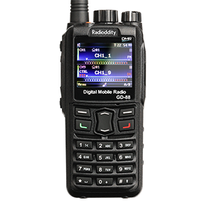
GD-88
Manuals & Software
Here you will find user manuals, device drivers and softwares for a wide range of our products.
ANALOG SERIES

R2
Manuals & Software
Here you will find user manuals, device drivers and softwares for a wide range of our products.

GA-2S
Manuals & Software
Here you will find user manuals, device drivers and softwares for a wide range of our products.

GA-5S
Manuals & Software
Here you will find user manuals, device drivers and softwares for a wide range of our products.

GA-510
Manuals & Software
Here you will find user manuals, device drivers and softwares for a wide range of our products.

GS-5B
Manuals & Software
Here you will find user manuals, device drivers and softwares for a wide range of our products.

GA-5E
Manuals & Software
Here you will find user manuals, device drivers and softwares for a wide range of our products.
Mobile Series

DB25/ DB25 Pro
Manuals & Software
Here you will find user manuals, device drivers and softwares for a wide range of our products.
QB25/ QB25 Pro
Manuals & Software
Here you will find user manuals, device drivers and softwares for a wide range of our products.

CB-27
Manuals & Software
Here you will find user manuals, device drivers and softwares for a wide range of our products.

CB-27 Pro
Manuals & Software
Here you will find user manuals, device drivers and softwares for a wide range of our products.

CS-47
Manuals & Software
Here you will find user manuals, device drivers and softwares for a wide range of our products.

DB20-G
Manuals & Software
Here you will find user manuals, device drivers and softwares for a wide range of our products.

DB20-UV
Manuals & Software
Here you will find user manuals, device drivers and softwares for a wide range of our products.

DB25-G
Manuals & Software
Here you will find user manuals, device drivers and softwares for a wide range of our products.

DB25-D
Manuals & Software
Here you will find user manuals, device drivers and softwares for a wide range of our products.
FRS & PMR SERIES

FS-T1 / PR-T1
Manuals & Software
Here you will find user manuals, device drivers and softwares for a wide range of our products.

FS-T2 / PR-T2
Manuals & Software
Here you will find user manuals, device drivers and softwares for a wide range of our products.

FS-T3 / PR-T3
Manuals & Software
Here you will find user manuals, device drivers and softwares for a wide range of our products.

PR-T5
Manuals & Software
Here you will find user manuals, device drivers and softwares for a wide range of our products.

R2 PMR446
Manuals & Software
Here you will find user manuals, device drivers and softwares for a wide range of our products.
GMRS & MURS SERIES

GM-30
Manuals & Software
Here you will find user manuals, device drivers and softwares for a wide range of our products.

GM-N1
Manuals & Software
Here you will find user manuals, device drivers and softwares for a wide range of our products.

MU-5
Manuals & Software
Here you will find user manuals, device drivers and softwares for a wide range of our products.
Others

Voyage RV6
Manuals & Software
Here you will find user manuals, device drivers and softwares for a wide range of our products.

GM Series
Manuals & Software
Here you will find user manuals, device drivers and softwares for a wide range of our products.

VR-P25U/UD
Manuals & Software
Here you will find user manuals, device drivers and softwares for a wide range of our products.

PAX100
Manuals & Software
Here you will find user manuals, device drivers and softwares for a wide range of our products.

LPFX7 & LPMX2
Manuals & Software
Here you will find user manuals, device drivers and softwares for a wide range of our products.

QR20
Manuals & Software
Here you will find user manuals, device drivers and softwares for a wide range of our products.
-

-
October 25 2017, 20:31
Стимулом для приобретения этой мобильной радиостанции было исследование DMR в калининградском регионе . Здесь, вроде бы, есть радиолюбительский репитер на двойке и ещё кто-то работает .
Первое виртуальное знакомство со станцией было в обзоре ЖЖ http://rv6lrj.livejournal.com/40460.html
Покупал на eBay в этом магазине https://www.ebay.com/usr/radioptimum
Цена на момент оплаты = 94.99$ via PayPal
Время доставки : оплачено 20-го сентября , 16-го октября прибыла в пункт назначения . Почта Нидерландов принимала участие , потом Шереметьево-Внуково, Павелецкий вокзал — Белорусский вокзал .
ТТХ и описание на офсайте https://www.radioddity.com
1. Галочка стоит в графе SALE OF GOODS . Origin : China . Value 12$ (объявленная ценность)
2.
3. Что внутри коробки :
Батарея
USB зарядка (от сотового зарядка не работает)
Адаптер питания
Мануал
Антенна на два диапазона
Защёлка на пояс (+ два винтика)
Радиостанция (само собой)
Кабель программирования
4. MADE IN CHINA
5.
6. Что открывается взору при открытии коробки . Сверху лежит инструкция . Малоинформативная, надо сказать. Представьте, там нет описания значков дисплея! 
7. Каждая единица комплекта упакована в плёнку
8. Клипса на пояс . Крепится двумя винтиками к корпусу
9. Переходник под евророзетку Sain Sonic . Похоже , бонус от продавца. Хорошо!
10. Зарядный стакан , диск с программой управления
11. Металлическое шасси и батарея на 2200 мАч / 7.4 Вольт
12. Посылка погуляла по Москве
13. Приятное оповещение от eBay
Потом напишу про версии программ