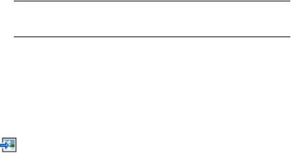
This tutorial introduces the following AutoCAD Raster Design toolset features:
- AutoCAD Raster Design toolset setup options
- Image management features
- Image properties
- Methods of saving images
In these exercises, you set AutoCAD Raster Design toolset options that control feature settings and learn how to control image display. Also, you learn how to view and modify the properties of an image or a group of images, and how to save modified images.
You should complete the exercises in this tutorial before continuing with the other AutoCAD Raster Design toolset tutorials. The subsequent tutorials assume that you are familiar with the features covered in these exercises.
You can access AutoCAD Raster Design toolset commands and features in the following ways:
- Raster menu
- Shortcut menu
- Raster Design Toolbar
Each of the tutorial exercises requires a specific drawing file from the Tutorials folder where AutoCAD Raster Design toolset is installed. For information on these drawing files, see Using the Tutorial Images and Drawings.
 Loading…
![]()
AutoCAD Raster Design 2010
User’s Guide
April 2009
© 2009 Autodesk, Inc. All Rights Reserved. Except as otherwise permitted by Autodesk, Inc., this publication, or parts thereof, may not be reproduced in any form, by any method, for any purpose.
Certain materials included in this publication are reprinted with the permission of the copyright holder.
Trademarks
The following are registered trademarks or trademarks of Autodesk, Inc., in the USA and other countries: 3DEC (design/logo), 3December, 3December.com, 3ds Max, ADI, Alias, Alias (swirl design/logo), AliasStudio, Alias|Wavefront (design/logo), ATC, AUGI, AutoCAD, AutoCAD Learning Assistance, AutoCAD LT, AutoCAD Simulator, AutoCAD SQL Extension, AutoCAD SQL Interface, Autodesk, Autodesk Envision, Autodesk Insight, Autodesk Intent, Autodesk Inventor, Autodesk Map, Autodesk MapGuide, Autodesk Streamline, AutoLISP, AutoSnap, AutoSketch, AutoTrack, Backdraft, Built with ObjectARX (logo), Burn, Buzzsaw, CAiCE, Can You Imagine, Character Studio, Cinestream, Civil 3D, Cleaner, Cleaner Central, ClearScale, Colour Warper, Combustion, Communication Specification, Constructware, Content Explorer, Create>what’s>Next> (design/logo), Dancing Baby (image), DesignCenter, Design Doctor, Designer’s Toolkit, DesignKids, DesignProf, DesignServer, DesignStudio, Design|Studio (design/logo), Design Web Format, Discreet, DWF, DWG, DWG (logo), DWG Extreme, DWG TrueConvert, DWG TrueView, DXF, Ecotect, Exposure, Extending the Design Team, Face Robot, FBX, Filmbox, Fire, Flame, Flint, FMDesktop, Freewheel, Frost, GDX Driver, Gmax, Green Building Studio, Heads-up Design, Heidi, HumanIK, IDEA Server, i-drop, ImageModeler, iMOUT, Incinerator, Inferno, Inventor, Inventor LT, Kaydara, Kaydara (design/logo), Kynapse, Kynogon, LandXplorer, LocationLogic, Lustre, Matchmover, Maya, Mechanical Desktop, Moonbox, MotionBuilder, Movimento, Mudbox, NavisWorks, ObjectARX, ObjectDBX, Open Reality, Opticore, Opticore Opus, PolarSnap, PortfolioWall, Powered with Autodesk Technology, Productstream, ProjectPoint, ProMaterials, RasterDWG, Reactor, RealDWG, Real-time Roto, REALVIZ, Recognize, Render Queue, Retimer,Reveal, Revit, Showcase, ShowMotion, SketchBook, Smoke, Softimage, Softimage|XSI (design/logo), SteeringWheels, Stitcher, Stone, StudioTools, Topobase, Toxik, TrustedDWG, ViewCube, Visual, Visual Construction, Visual Drainage, Visual Landscape, Visual Survey, Visual Toolbox, Visual LISP, Voice Reality, Volo, Vtour, Wire, Wiretap, WiretapCentral, XSI, and XSI (design/logo).
The following are registered trademarks or trademarks of Autodesk Canada Co. in the USA and/or Canada and other countries: Backburner,Multi-Master Editing, River, and Sparks.
The following are registered trademarks or trademarks of MoldflowCorp. in the USA and/or other countries: Moldflow, MPA, MPA (design/logo),Moldflow Plastics Advisers, MPI, MPI (design/logo), Moldflow Plastics Insight,MPX, MPX (design/logo), Moldflow Plastics Xpert.
All other brand names, product names or trademarks belong to their respective holders.
Disclaimer
THIS PUBLICATION AND THE INFORMATION CONTAINED HEREIN IS MADE AVAILABLE BY AUTODESK, INC. «AS IS.» AUTODESK, INC. DISCLAIMS ALL WARRANTIES, EITHER EXPRESS OR IMPLIED, INCLUDING BUT NOT LIMITED TO ANY IMPLIED WARRANTIES OF MERCHANTABILITY OR FITNESS FOR A PARTICULAR PURPOSE REGARDING THESE MATERIALS.
Published by: Autodesk, Inc.
111 Mclnnis Parkway
San Rafael, CA 94903, USA
Contents
Chapter 1 Introduction to AutoCAD Raster Design 2010 . . . . . . . . . . . 1
What is New in AutoCAD Raster Design 2010 . . . . . . . . . . . . . . . 1 Accessing the Raster Design Home Page . . . . . . . . . . . . . . . . . . 4 About AutoCAD Raster Design dialog box . . . . . . . . . . . . . . . . . 5 Installation Requirements . . . . . . . . . . . . . . . . . . . . . . . . . 5 Supported Image Formats . . . . . . . . . . . . . . . . . . . . . . . . . 5 Image Portability . . . . . . . . . . . . . . . . . . . . . . . . . . . . . . 6 AutoCAD Raster Design History . . . . . . . . . . . . . . . . . . . . . . 7
Chapter 2 Inserting and Correlating Images . . . . . . . . . . . . . . . . . 9
Inserting Images . . . . . . . . . . . . . . . . . . . . . . . . . . . . . . 9 Inserting Local Images Using the Insert Image Dialog Box . . . . . 10 Inserting an Image from the Internet Using the Insert Image
Dialog Box . . . . . . . . . . . . . . . . . . . . . . . . . . . . . 12 Inserting an Image from an FTP Site Using the Insert Image
Dialog Box . . . . . . . . . . . . . . . . . . . . . . . . . . . . . 14 Inserting an Image Using the Command Line . . . . . . . . . . . 16 Adding Image Sources to Favorites . . . . . . . . . . . . . . . . . 18 Assigning a Color Map to an Image . . . . . . . . . . . . . . . . . 18 Creating New Images . . . . . . . . . . . . . . . . . . . . . . . . 20
Correlating Images . . . . . . . . . . . . . . . . . . . . . . . . . . . . 21 Correlating an Image During Insertion . . . . . . . . . . . . . . . 21 Using Quick Insert . . . . . . . . . . . . . . . . . . . . . . . . . 22
iii
Specifying Correlation Settings . . . . . . . . . . . . . . . . . . . 23 Adjusting the Image Frame Before Insertion . . . . . . . . . . . . 27 Correlating an Image After Insertion . . . . . . . . . . . . . . . . 28 Matching Image Points . . . . . . . . . . . . . . . . . . . . . . . 28 Moving an Image . . . . . . . . . . . . . . . . . . . . . . . . . . 29 Scaling an Image . . . . . . . . . . . . . . . . . . . . . . . . . . 30 Rubbersheeting an Image . . . . . . . . . . . . . . . . . . . . . . 31
Chapter 3 Saving Images . . . . . . . . . . . . . . . . . . . . . . . . . . . 39
Saving an Image . . . . . . . . . . . . . . . . . . . . . . . . . . . . . . 39 Saving Images with AutoCAD Save . . . . . . . . . . . . . . . . . . . . 41 Embedding Images in a Drawing . . . . . . . . . . . . . . . . . . . . . 42 Saving an Image to Another File Name, Type, or Location . . . . . . . . 43 Saving an Image to an FTP Site . . . . . . . . . . . . . . . . . . . . . . 45 Capturing an Image . . . . . . . . . . . . . . . . . . . . . . . . . . . . 47 Exporting Images . . . . . . . . . . . . . . . . . . . . . . . . . . . . . 48
Exporting an Image . . . . . . . . . . . . . . . . . . . . . . . . . 49 Exporting an Image to an FTP Site . . . . . . . . . . . . . . . . . 51 Exporting a World File . . . . . . . . . . . . . . . . . . . . . . . 52 Correlation Output Types . . . . . . . . . . . . . . . . . . . . . . 54 Encoding and Data Organization Methods . . . . . . . . . . . . . 54
Chapter 4 Changing Image Properties . . . . . . . . . . . . . . . . . . . . 57
AutoCAD Properties . . . . . . . . . . . . . . . . . . . . . . . . . . . . 57 Image Display Properties . . . . . . . . . . . . . . . . . . . . . . . . . 58 Image Display Quality . . . . . . . . . . . . . . . . . . . . . . . . . . . 58 Image Frame Display . . . . . . . . . . . . . . . . . . . . . . . . . . . 59 Image Layer . . . . . . . . . . . . . . . . . . . . . . . . . . . . . . . . 60 Linetype of an Image Frame . . . . . . . . . . . . . . . . . . . . . . . . 61 Foreground Color of a Bitonal Image . . . . . . . . . . . . . . . . . . . 61 Transparency Color of an Image . . . . . . . . . . . . . . . . . . . . . 62 Unused Color for Transparent Color . . . . . . . . . . . . . . . . . . . 63
Chapter 5 Managing Images and Insertions . . . . . . . . . . . . . . . . . 65
Controlling the Image Manager Toolspace . . . . . . . . . . . . . . . . 65 Modifying the Item View Layout . . . . . . . . . . . . . . . . . . 65 Copying Information to the Clipboard . . . . . . . . . . . . . . . 66 Managing Image Display and Data . . . . . . . . . . . . . . . . . . . . 67 Zooming to an Image . . . . . . . . . . . . . . . . . . . . . . . . 67 Changing the Color Map of an Image . . . . . . . . . . . . . . . 68 Adding a Visual Elevation Key to a DEM Image . . . . . . . . . . 69 Creating Another Insertion of an Image . . . . . . . . . . . . . . 70 Displaying Point Data . . . . . . . . . . . . . . . . . . . . . . . . 71 Showing and Hiding Images . . . . . . . . . . . . . . . . . . . . 72
iv | Contents
Changing the Display Order of Images . . . . . . . . . . . . . . . 73 Erasing an Image . . . . . . . . . . . . . . . . . . . . . . . . . . 74 Detaching an Image . . . . . . . . . . . . . . . . . . . . . . . . . 74 Unloading/Reloading an Image . . . . . . . . . . . . . . . . . . . 75 Changing the Active Path . . . . . . . . . . . . . . . . . . . . . . 75 Changing the Saved Path . . . . . . . . . . . . . . . . . . . . . . 76
Chapter 6 Modifying Images . . . . . . . . . . . . . . . . . . . . . . . . . 79
Selecting an Image . . . . . . . . . . . . . . . . . . . . . . . . . . . . 79 Controlling Image Frames . . . . . . . . . . . . . . . . . . . . . . . . . 81 Undoing Edits to an Image . . . . . . . . . . . . . . . . . . . . . . . . 81 Snapping to COGO Points . . . . . . . . . . . . . . . . . . . . . . . . 82 Cleaning Up Images . . . . . . . . . . . . . . . . . . . . . . . . . . . . 82
Deskewing an Image . . . . . . . . . . . . . . . . . . . . . . . . 83 Removing Speckles from an Image . . . . . . . . . . . . . . . . . 84 Adjusting the Image Bias . . . . . . . . . . . . . . . . . . . . . . 86 Reversing the Light and Dark Shades in an Image . . . . . . . . . 88 Mirroring an Image . . . . . . . . . . . . . . . . . . . . . . . . . 88 Touching Up an Image . . . . . . . . . . . . . . . . . . . . . . . 89
Image Processing . . . . . . . . . . . . . . . . . . . . . . . . . . . . . 91 Adjusting Images with the Histogram . . . . . . . . . . . . . . . 92 Adjusting the Brightness and Contrast of an Image . . . . . 92 Maximizing Details in an Image . . . . . . . . . . . . . . . 96 Converting a Color Image to Grayscale . . . . . . . . . . . 98 Converting a Grayscale or Color Image to Bitonal . . . . . 100 Making Tonal Adjustments to an Image . . . . . . . . . . 101 Convolving an Image . . . . . . . . . . . . . . . . . . . . . . . 105 Reducing Harshness and Noise in an Image . . . . . . . . 105 Median Filter . . . . . . . . . . . . . . . . . . . . . . . . . 106 Making Differences in Shading More Distinct . . . . . . . 107 Lowpass Filtering . . . . . . . . . . . . . . . . . . . . . . 108 Highpass Filters . . . . . . . . . . . . . . . . . . . . . . . 109 Edge Enhancements Filters . . . . . . . . . . . . . . . . . 110 Shift and Difference Edge Enhancements Filters . . . . . . 110 Laplace Edge Enhancements Filters . . . . . . . . . . . . . 110 Gradient Directional Edge Enhancements Filters . . . . . . 111 Matched Filter Edge Enhancements Filters . . . . . . . . . 111 Using Bitonal Filters . . . . . . . . . . . . . . . . . . . . . 112 Changing Image Density . . . . . . . . . . . . . . . . . . 115 Setting the Color Depth for an Image . . . . . . . . . . . . 116
Using the Palette Manager . . . . . . . . . . . . . . . . . . . . . . . . 118 Manipulating the Color Table . . . . . . . . . . . . . . . . . . . 118 Changing Selected Colors in the Image Palette . . . . . . . 118 Combining Selected Colors in the Image Palette . . . . . . 120 Designating a Transparent Color . . . . . . . . . . . . . . 121 Selecting a Color Directly from the Image . . . . . . . . . 122
Contents | v
Removing Duplicate Entries from the Image Palette . . . . 123 Resetting the Image Palette . . . . . . . . . . . . . . . . . 124 Importing and Exporting Image Palettes . . . . . . . . . . . . . 125 Importing an Image Palette . . . . . . . . . . . . . . . . . 125 Exporting an Image Palette . . . . . . . . . . . . . . . . . 128 Displaying Image Palette Information . . . . . . . . . . . 129 Converting Grayscale Images to Paletted Images . . . . . . 130 Controlling Palette Views . . . . . . . . . . . . . . . . . . . . . 131 Controlling the Display of Unused Colors . . . . . . . . . 131 Controlling the Display of Transparent Colors . . . . . . . 132 Controlling the Display of Color Values . . . . . . . . . . 133 Sorting the Color Table . . . . . . . . . . . . . . . . . . . 134
Adding and Removing Columns from the List
Window . . . . . . . . . . . . . . . . . . . . . . . . . . 135 Masking Images . . . . . . . . . . . . . . . . . . . . . . . . . . . . . 136 Creating a New Mask . . . . . . . . . . . . . . . . . . . . . . . 137 Creating a New Mask Using the Command Line . . . . . . . . . 138 Changing an Existing Mask . . . . . . . . . . . . . . . . . . . . 138 Changing the Image Mask Properties . . . . . . . . . . . . 139
Changing an Existing Mask Using the Command
Line . . . . . . . . . . . . . . . . . . . . . . . . . . . . . 140 Enabling or Disabling a Mask . . . . . . . . . . . . . . . . 141 Clipping an Image . . . . . . . . . . . . . . . . . . . . . . . . . 142 Converting a Mask to Image Clips . . . . . . . . . . . . . . . . 143
Cropping Images . . . . . . . . . . . . . . . . . . . . . . . . . . . . . 144 Line Cropping . . . . . . . . . . . . . . . . . . . . . . . . . . . 145 Circular Cropping . . . . . . . . . . . . . . . . . . . . . . . . . 145 Rectangular Cropping . . . . . . . . . . . . . . . . . . . . . . . 146 Diagonal Cropping . . . . . . . . . . . . . . . . . . . . . . . . . 147 Polygonal Cropping . . . . . . . . . . . . . . . . . . . . . . . . 147 Aligned Rectangular Cropping . . . . . . . . . . . . . . . . . . . 148
Removing (Rubbing) Images . . . . . . . . . . . . . . . . . . . . . . . 149 Rubbing a Raster Line . . . . . . . . . . . . . . . . . . . . . . . 149 Rubbing a Raster Arc . . . . . . . . . . . . . . . . . . . . . . . . 150 Rubbing a Raster Circle . . . . . . . . . . . . . . . . . . . . . . 151 Rubbing Multiple Line Segments . . . . . . . . . . . . . . . . . 151 Rubbing Raster Data Within a Circular Region . . . . . . . . . . 152 Rubbing Raster Data Within a Diagonal Region . . . . . . . . . 153 Rubbing Raster Data Within a Polygonal Region . . . . . . . . . 154 Rubbing Raster Data Within a Rectangular Region . . . . . . . . 155 Remove Raster Using Existing Vector Geometry . . . . . . . . . 155 Removing Raster Entities Using REM Commands . . . . . . . . . 156
Removing a Line, Arc, or Circle Using Smart Pick . . . . . 157 Removing a REM Line Primitive . . . . . . . . . . . . . . . 158 Removing a REM Arc Primitive . . . . . . . . . . . . . . . 158 Removing a REM Circle Primitive . . . . . . . . . . . . . . 159
vi | Contents
Merging Objects . . . . . . . . . . . . . . . . . . . . . . . . . . . . . 160 Merging Images . . . . . . . . . . . . . . . . . . . . . . . . . . 160 Merging Vectors into a Raster Image . . . . . . . . . . . . . . . 161 Selecting Pen Widths for Vector Merge . . . . . . . . . . . . . . 162
Chapter 7 Raster Entity Manipulation . . . . . . . . . . . . . . . . . . . 165
Characteristics of REM Objects . . . . . . . . . . . . . . . . . . . . . 166 How REM Objects Are Associated with an Image . . . . . . . . . 166 Deciding Which Image to Use REM Commands On . . . . . . . 166 AutoCAD Properties of REM Objects . . . . . . . . . . . . . . . 167 REM Objects and Non-REM Edits . . . . . . . . . . . . . . . . . 167
Defining REM Region Objects . . . . . . . . . . . . . . . . . . . . . . 168 Defining a REM Rectangular Region . . . . . . . . . . . . . . . . 169 Defining a REM Polygonal Region . . . . . . . . . . . . . . . . . 170 Defining a REM Diagonal Region . . . . . . . . . . . . . . . . . 171 Defining a REM Circular Region . . . . . . . . . . . . . . . . . . 172 Defining a Region From an Existing Vector Object . . . . . . . . 174 Removing Part of a Region Object . . . . . . . . . . . . . . . . . 175
Defining REM Enhanced Bitonal Regions . . . . . . . . . . . . . . . . 176 Defining REM Primitive Objects . . . . . . . . . . . . . . . . . . . . . 178 Defining a REM Line Primitive . . . . . . . . . . . . . . . . . . 180 Defining a REM Circle Primitive . . . . . . . . . . . . . . . . . . 181 Defining a REM Arc Primitive . . . . . . . . . . . . . . . . . . . 183 Defining a REM Primitive Using Smart Pick . . . . . . . . . . . . 184 Defining a REM Primitive From Existing Vectors . . . . . . . . . 185 Changing the Linetype of a Primitive Object . . . . . . . . . . . 186 Manipulating REM Objects . . . . . . . . . . . . . . . . . . . . . . . 187 Editing REM Objects . . . . . . . . . . . . . . . . . . . . . . . . 187 Resizing a REM Object . . . . . . . . . . . . . . . . . . . . . . . 189 Using REM Operations . . . . . . . . . . . . . . . . . . . . . . . 191 Trimming and Extending REM Lines . . . . . . . . . . . . 191 Filleting REM Lines . . . . . . . . . . . . . . . . . . . . . 192 Offsetting REM Objects . . . . . . . . . . . . . . . . . . . 193 Smoothing REM Linework . . . . . . . . . . . . . . . . . . 194 Defining REM Objects Partially Outside the Image . . . . . . . . 195 Using REM to Delete Raster Data . . . . . . . . . . . . . . . . . 195 Clearing REM Objects . . . . . . . . . . . . . . . . . . . . . . . 197 Merging REM Objects into an Image . . . . . . . . . . . . . . . 198 Converting REM Objects to a New Raster Image . . . . . . . . . 199 Using REM Transparency . . . . . . . . . . . . . . . . . . . . . 200 Using REM Copy To Clipboard Command . . . . . . . . . . . . 200 Separating Raster Linework Using Knife . . . . . . . . . . . . . . 201
Chapter 8 Converting Raster Entities to Vector . . . . . . . . . . . . . . 203
Configuring VTools . . . . . . . . . . . . . . . . . . . . . . . . . . . 204
Contents | vii
ProdNameShort Options . . . . . . . . . . . . . . . . . . . . . . 204 Dynamic Input Settings . . . . . . . . . . . . . . . . . . . . . . 204 Using SmartCorrect . . . . . . . . . . . . . . . . . . . . . . . . . . . 205 Vectorizing Raster Geometry . . . . . . . . . . . . . . . . . . . . . . . 206 Vectorizing Raster Lines and Polylines . . . . . . . . . . . . . . 207 Vectorizing Raster Rectangles . . . . . . . . . . . . . . . . . . . 212 Vectorizing Raster Circles . . . . . . . . . . . . . . . . . . . . . 213 Vectorizing Raster Arcs . . . . . . . . . . . . . . . . . . . . . . . 215 Following Polylines . . . . . . . . . . . . . . . . . . . . . . . . . . . 217 Using the Polyline Follower . . . . . . . . . . . . . . . . . . . . 219 Using the Contour Follower . . . . . . . . . . . . . . . . . . . . 220 Using the 3D Polyline Follower . . . . . . . . . . . . . . . . . . 223 Vectorizing Raster Text . . . . . . . . . . . . . . . . . . . . . . . . . . 225 Creating Single-Line Vector Text . . . . . . . . . . . . . . . . . 226 Creating Multiline Vector Text . . . . . . . . . . . . . . . . . . 228 Using Text Recognition . . . . . . . . . . . . . . . . . . . . . . 230 Entering Settings for Text Recognition . . . . . . . . . . . 230 Recognizing and Converting Text . . . . . . . . . . . . . . 232 Using the Verify Text Window . . . . . . . . . . . . . . . . . . . 234 View Window Options . . . . . . . . . . . . . . . . . . . . . . . 235 Edit Pane Options . . . . . . . . . . . . . . . . . . . . . . . . . 235
Chapter 9 Raster Snapping . . . . . . . . . . . . . . . . . . . . . . . . . 237
Specifying Raster Snap Settings . . . . . . . . . . . . . . . . . . . . . 237 Snap Modes . . . . . . . . . . . . . . . . . . . . . . . . . . . . . . . 238
Chapter 10 Configuring Raster Design . . . . . . . . . . . . . . . . . . . . 241
Changing the Quick Bar Visibility . . . . . . . . . . . . . . . . . . . . 241 Changing the Image Frame Visibility . . . . . . . . . . . . . . . . . . 242 Setting the Default Internet Location for Images . . . . . . . . . . . . 242 Setting the Options . . . . . . . . . . . . . . . . . . . . . . . . . . . 244 Contour Vector Separation Options . . . . . . . . . . . . . . . . 244 Correlation Defaults . . . . . . . . . . . . . . . . . . . . . . . . 245 Correlation Search Paths . . . . . . . . . . . . . . . . . . . . . . 247 General Vector Separation Options . . . . . . . . . . . . . . . . 249 General VTool Settings . . . . . . . . . . . . . . . . . . . . . . . 250 Image Detach Method . . . . . . . . . . . . . . . . . . . . . . . 252 Image Defaults . . . . . . . . . . . . . . . . . . . . . . . . . . . 253 Image Mask Options . . . . . . . . . . . . . . . . . . . . . . . . 254 Image Thumbnails . . . . . . . . . . . . . . . . . . . . . . . . . 255 Inserting Images From GSX or ESP . . . . . . . . . . . . . . . . 256 Locking Method for Image Files . . . . . . . . . . . . . . . . . . 258 Message Display Method . . . . . . . . . . . . . . . . . . . . . 259 Mouse Settings . . . . . . . . . . . . . . . . . . . . . . . . . . . 260 New Image Defaults . . . . . . . . . . . . . . . . . . . . . . . . 261
viii | Contents
QSave Preference . . . . . . . . . . . . . . . . . . . . . . . . . . 262 Raster Design Startup Options . . . . . . . . . . . . . . . . . . . 263 Raster Entity Detection Settings . . . . . . . . . . . . . . . . . . 264 REM Settings . . . . . . . . . . . . . . . . . . . . . . . . . . . . 265 Rub and Crop Line Width . . . . . . . . . . . . . . . . . . . . . 266 Remove Under Method . . . . . . . . . . . . . . . . . . . . . . 268 Vector Merge Settings . . . . . . . . . . . . . . . . . . . . . . . 268 VTools Follower Settings . . . . . . . . . . . . . . . . . . . . . . 270
Appendix A Troubleshooting and Reference Guide . . . . . . . . . . . . . 273
Troubleshooting . . . . . . . . . . . . . . . . . . . . . . . . . . . . . 273 Correcting Image Display Order using REGEN . . . . . . . . . . 273 Raster Snap Troubleshooting . . . . . . . . . . . . . . . . . . . 274 Plotting Raster Images . . . . . . . . . . . . . . . . . . . . . . . 274 Images that are Not Editable . . . . . . . . . . . . . . . . . . . . 274 Problems Inserting Images from the Internet . . . . . . . . . . . 275 Sharing Projects with Images from Different Locations . . . . . . 276
Command-Line Commands . . . . . . . . . . . . . . . . . . . . . . . 276 AutoCAD Commands for Images . . . . . . . . . . . . . . . . . . . . 285 Image Menu . . . . . . . . . . . . . . . . . . . . . . . . . . . . . . . 286 Toolbars . . . . . . . . . . . . . . . . . . . . . . . . . . . . . . . . . 288 Raster Design Toolbar . . . . . . . . . . . . . . . . . . . . . . . 288 Raster Entity Manipulation Toolbars . . . . . . . . . . . . . . . 294 The Quick Bar . . . . . . . . . . . . . . . . . . . . . . . . . . . 298
Appendix B Raster Design Dialog Boxes . . . . . . . . . . . . . . . . . . . 301
About AutoCAD Raster Design Box . . . . . . . . . . . . . . . . . . . 301 Assign Multispectral Band Dialog Box . . . . . . . . . . . . . . . . . . 301 Band Assignment Color Map Dialog Box . . . . . . . . . . . . . . . . 301 Bitonal Filters Dialog Box . . . . . . . . . . . . . . . . . . . . . . . . 302 Change Density Dialog Box . . . . . . . . . . . . . . . . . . . . . . . 303 Choose a New Directory Dialog Box . . . . . . . . . . . . . . . . . . . 303 Choose a Resource File Directory Dialog Box . . . . . . . . . . . . . . 304 Coordinate System Assignment Dialog Box . . . . . . . . . . . . . . . 305 Data Organization Dialog Box . . . . . . . . . . . . . . . . . . . . . . 307 Despeckle Dialog Box . . . . . . . . . . . . . . . . . . . . . . . . . . 307 Display Manager Raster Layer Capture Dialog Box . . . . . . . . . . . 307 Drafting Settings Dialog Box . . . . . . . . . . . . . . . . . . . . . . . 308
Raster Snap Tab (Drafting Settings Dialog Box) . . . . . . . . . . 309 Edit Status Dialog Box . . . . . . . . . . . . . . . . . . . . . . . . . . 310 Encoding Method Dialog Box . . . . . . . . . . . . . . . . . . . . . . 311 Export Dialog Box . . . . . . . . . . . . . . . . . . . . . . . . . . . . 311 Export Options Dialog Box . . . . . . . . . . . . . . . . . . . . . . . 313 Export Palette Dialog Box . . . . . . . . . . . . . . . . . . . . . . . . 314 GeoTIFF Coordinate System Properties Dialog Box . . . . . . . . . . . 315
Contents | ix
Grid Parameters Dialog Box . . . . . . . . . . . . . . . . . . . . . . . 315 Histogram Dialog Box . . . . . . . . . . . . . . . . . . . . . . . . . . 316 Brightness/Contrast Tab (Histogram Dialog Box) . . . . . . . . . 316 Equalize Tab (Histogram Dialog Box) . . . . . . . . . . . . . . . 318 Threshold Tab (Histogram Dialog Box) . . . . . . . . . . . . . . 320 Color to Grayscale Tab (Histogram Dialog Box) . . . . . . . . . . 321 Tonal Adjustment Tab (Histogram Dialog Box) . . . . . . . . . . 322 Image Data Properties Dialog Box . . . . . . . . . . . . . . . . . . . . 324 Image Filters Dialog Box . . . . . . . . . . . . . . . . . . . . . . . . . 324 Image Insertion Dialog Box . . . . . . . . . . . . . . . . . . . . . . . 325 Assign Color Map Tab (Image Insertion Dialog Box) . . . . . . . 325 Source Tab (Image Insertion Dialog Box) . . . . . . . . . . . . . 326 Modify Tab (Image Insertion Dialog Box) . . . . . . . . . . . . . 327 Insertion Tab (Image Insertion Dialog Box) . . . . . . . . . . . . 328 Transform Tab (Image Insertion Dialog Box) . . . . . . . . . . . 329 Image Manager Toolspace . . . . . . . . . . . . . . . . . . . . . . . . 330 Image Insertions View (Image Manager Toolspace) . . . . . . . . 331 Image Data View (Image Manager Toolspace) . . . . . . . . . . . 332 Image Select Dialog Box . . . . . . . . . . . . . . . . . . . . . . . . . 335 Import Data Dialog Box . . . . . . . . . . . . . . . . . . . . . . . . . 336 Import Palette Dialog Box . . . . . . . . . . . . . . . . . . . . . . . . 337 Insert Image Dialog Box . . . . . . . . . . . . . . . . . . . . . . . . . 338 Median Filter Dialog Box . . . . . . . . . . . . . . . . . . . . . . . . 340 Mirror Dialog Box . . . . . . . . . . . . . . . . . . . . . . . . . . . . 341 Multi-frame Select Dialog Box . . . . . . . . . . . . . . . . . . . . . . 341 New Image Dialog Box . . . . . . . . . . . . . . . . . . . . . . . . . . 342 New Image Mask Dialog Box . . . . . . . . . . . . . . . . . . . . . . 343 New Palette Color Insertion Dialog Box . . . . . . . . . . . . . . . . . 344 Palette Assignment Color Map Dialog Box . . . . . . . . . . . . . . . 345 Palette Color Map Definition Dialog Box . . . . . . . . . . . . . . . . 345 Palette Information Dialog Box . . . . . . . . . . . . . . . . . . . . . 348 Palette Manager Dialog Box . . . . . . . . . . . . . . . . . . . . . . . 348 Raster Data Query Dialog Box . . . . . . . . . . . . . . . . . . . . . . 350 Raster Design Options Dialog Box . . . . . . . . . . . . . . . . . . . . 351 Image Defaults Tab (Raster Design Options Dialog Box) . . . . . 351 Feature Settings Tab (Raster Design Options Dialog Box) . . . . . 352 Image Mask Tab (Raster Design Options Dialog Box) . . . . . . . 353 New Image Tab (Raster Design Options Dialog Box) . . . . . . . 354 Paths Tab (Raster Design Options Dialog Box) . . . . . . . . . . 355 REM Tab (Raster Design Options Dialog Box) . . . . . . . . . . . 357
Raster Entity Detection Tab (Raster Design Options Dialog
Box) . . . . . . . . . . . . . . . . . . . . . . . . . . . . . . . 357 User Preferences Tab (Raster Design Options Dialog Box) . . . . 358 Vector Merge Tab (Raster Design Options Dialog Box) . . . . . . 359 VTools Follower Tab (Raster Design Options Dialog Box) . . . . . 360 VTools General Tab (Raster Design Options Dialog Box) . . . . . 362
x | Contents
Raster Pen Settings Dialog Box . . . . . . . . . . . . . . . . . . . . . . 363 Recognition Character Sets Dialog Box . . . . . . . . . . . . . . . . . 364 Rubbersheet — Set Control Points Dialog Box . . . . . . . . . . . . . . 364 Save As Dialog Box . . . . . . . . . . . . . . . . . . . . . . . . . . . . 366 Select a Lock File Directory Dialog Box . . . . . . . . . . . . . . . . . 367 Select Coordinate System (Export) Dialog Box . . . . . . . . . . . . . 368 Select Coordinate System (Insert) Dialog Box . . . . . . . . . . . . . . 369 Select Global Coordinate System Dialog Box . . . . . . . . . . . . . . 369 Select Working Coordinate System Dialog Box . . . . . . . . . . . . . 369 Target Color Dialog Box . . . . . . . . . . . . . . . . . . . . . . . . . 370 Temporary File Location Dialog Box . . . . . . . . . . . . . . . . . . . 370 Text Recognition Setup Dialog Box . . . . . . . . . . . . . . . . . . . 371 Transparency Color Dialog Box . . . . . . . . . . . . . . . . . . . . . 373 Vector Separation Options Dialog Box . . . . . . . . . . . . . . . . . 373
General Tab (Vector Separation Options Dialog Box) . . . . . . . 373 Contour Tab (Vector Separation Options Dialog Box) . . . . . . 375 Verify Text/Table Dialog Box . . . . . . . . . . . . . . . . . . . . . . . 376 VText Edit Dialog Box . . . . . . . . . . . . . . . . . . . . . . . . . . 379
Glossary . . . . . . . . . . . . . . . . . . . . . . . . . . . . . 381
Index . . . . . . . . . . . . . . . . . . . . . . . . . . . . . . . 403
Contents | xi
xii

|
Introduction to AutoCAD |
1 |
|
Raster Design 2010 |
The AutoCAD Raster Design User’s Guide includes conceptual, procedural, and reference details about the tools and features found in AutoCAD Raster Design 2010.
This chapter provides information to help you get acquainted with Raster Design requirements, capabilities, and history.
What is New in AutoCAD Raster Design 2010
AutoCAD Raster Design 2010 builds on the features introduced in Raster Design
|
2009. |
|
|
New in Raster Design 2010 |
|
|
Function |
Description |
|
Citrix support |
AutoCAD Raster Design 2010 is now avail- |
|
able for use on Citrix XenApp v4.5 and 5.0 |
|
|
for use with AutoCAD Map 3D 2010. |
|
|
Additional Autodesk product support |
AutoCAD Raster Design 2010 can now be |
|
used with AutoCAD P&ID 2010 and |
|
|
Autodesk Topobase 2010. |
|
|
Improved image format support |
Support for TIFF and BIL image formats |
|
had been improved. In addition, AutoCAD |
|
|
Raster Design 2010 now includes 64-bit |
|
|
MrSID Codec support. |
1

|
New in Raster Design 2010 |
||
|
Function |
Description |
|
|
Updated ribbon |
The ribbon interface has been updated to |
|
|
be even easier to use. |
||
|
New in Raster Design 2009 |
||
|
Function |
Description |
|
|
64-bit support |
AutoCAD Raster Design 2010 supports |
|
|
both the 32-bit and 64-bit environments |
||
|
of its hosting Autodesk products. This will |
||
|
allow you to easily and confidently install |
||
|
AutoCAD Raster Design 2010 on any sup- |
||
|
porting application, using any of its suppor- |
||
|
ted operating systems. |
||
|
Discrete-themed data handling |
Discrete-themed data is a form of raster |
|
|
data commonly used to represent such |
||
|
things as land cover, zoning, and any other |
||
|
classified data. Coupled with the continu- |
||
|
ous-themed data handling required for |
||
|
working with elevations, this provides a |
||
|
much more robust environment for accur- |
||
|
ately using raster grid data. |
||
|
Vista ribbon-style interface |
This interface presents command options |
|
|
in a concise visual format, enabling you to |
||
|
quickly select commands based on the |
||
|
work you are doing. Moving between ap- |
||
|
plications is now quick and intuitive. The |
||
|
ribbon is both customizable and expand- |
||
|
able, so it can be optimized for each user |
||
|
and to meet each company’s standards. |
||
|
New in Raster Design 2008 |
||
|
Function |
Description |
|
|
Support for additional image formats |
Read images in these formats: |
|
|
■ |
QuickBird TIFF |
|
|
■ |
Landsat FAST |
2 | Chapter 1 Introduction to AutoCAD Raster Design 2010

|
New in Raster Design 2008 |
|
|
Function |
Description |
|
■ NITF (National Image Transmission |
|
|
Format) |
|
|
Vectorization improvements |
Prompts during vectorization operations |
|
can display conveniently near the cursor, |
|
|
using AutoCAD Dynamic Input. Grips ap- |
|
|
pear on previously vectorized segments to |
|
|
facilitate editing. |
|
|
Editing multi-resolution images |
Edit MrSID, ECW, and JPEG2000 images, |
|
then save changes in JPEG2000 format. |
|
|
Image embedding |
Embed one or more bitonal images inside |
|
the drawing for convenience of image |
|
|
transfer and management. |
|
|
Improved insert options |
The insert process has been improved with |
|
better image preview handling, support |
|
|
for multi-frame images, better indication |
|
|
when default settings are being applied, |
|
|
and enhanced control over coordinate |
|
|
transforms. |
|
|
Enhanced image capture |
When used with AutoCAD Map 3D, Raster |
|
Design can capture FDO (Feature Data |
|
|
Object) data, either in source format, or as |
|
|
stylized by Display Manager. |
|
|
Improved Despeckle |
Procedures are streamlined to make des- |
|
peckle operations easier and more effective. |
|
|
New in Raster Design 2007 |
|
|
Function |
Description |
|
DTED format support |
Read images in this format. |
|
ESRI Grid format support |
Read images in both ASCII and binary ver- |
|
sions of this format. |
What is New in AutoCAD Raster Design 2010 | 3

|
New in Raster Design 2007 |
|
|
Function |
Description |
|
Coordinate system transformation |
Automatic assignment of the Autodesk |
|
Map coordinate system code when insert- |
|
|
ing a GeoTIFF or DEM file. Also, automatic |
|
|
assignment of the correct EPSG code when |
|
|
exporting to GeoTIFF format. |
|
|
New in Raster Design 2006 |
|
|
Function |
Description |
|
Touchup tools for bitonal images |
Edit images at the pixel level. |
|
REM Operations tools |
Extend and trim raster lines to intersec- |
|
tions, add corner fillets, and offset lines. |
|
|
Raster Data Query dialog box |
Display data about the pixel under the |
|
cursor, such as color value, elevation, and |
|
|
coordinates in the specified coordinate |
|
|
system. |
|
|
Transform and edit complex image data |
When using Autodesk Map 3D, transform |
|
the coordinate system of 16-bit, multispec- |
|
|
tral or digital elevation models (DEM) to |
|
|
match a drawing coordinate system. |
|
|
Write to more image formats |
Save images to JPG 2000 format, and write |
|
DEM data to GeoTIFF or DEM format |
|
|
Image Capture |
Save displayed images from satellite data, |
|
digital elevation models, and other data |
|
|
types that cannot be otherwise saved. |
|
|
Default file name formats |
Names now reflect the image source and |
|
sequence number. |
Accessing the Raster Design Home Page
If you have an Internet connection, then you can access the Raster Design home page for information about product updates.
4 | Chapter 1 Introduction to AutoCAD Raster Design 2010

To access the Raster Design home page
■On the Image menu, select Raster Design Home Page. or click  in the Raster Design toolbar.
About AutoCAD Raster Design dialog box
This dialog box provides you with the following information about Raster Design:
■Name of the licensed owner
■Serial number
■Source of the licence
Installation Requirements
For hardware and software system requirements, refer to System Requirements for a Single User or System Requirements for Network Installations.
If your computer does not meet the minimum requirements, you should upgrade your computer before installing Raster Design.
Supported Image Formats
Raster Design can support most single-image and multispectral file formats. For multispectral files, Raster Design can read most common formats, but can best interpret metadata for the formats listed in the following table.
Image Formats Supported by Raster Design
|
Read-Write |
Read Only |
||
|
bitmap (BMP) |
CALS (page 383) |
DOQ (page 388) |
DTED (page 388) |
|
(page 382) |
|||
|
DEM (page 387) |
GeoTIFF (page |
ECW (page 388) |
ESRI Grid (page |
|
390) |
389) |
About AutoCAD Raster Design dialog box | 5

|
Image Formats Supported by Raster Design |
|||
|
GIF (page 390) |
JFIF — JPEG (page |
FLIC (page 389) |
Generic multispec- |
|
391) |
tral |
||
|
JPEG 2000 (page |
PCX (page 394) |
GeoSPOT (page |
GIF (page 390) |
|
391) |
390) |
||
|
PNG (page 394) |
TARGA (page 399) |
IG4 (page 391) |
IKONOS (8- or 16- |
|
bit) |
|||
|
TIFF (page 399) |
Landsat FAST L7A |
NITF (page 393) |
|
|
(page 392) |
|||
|
PICT (page 394) |
QuickBird TIFF |
||
|
(page 394) |
|||
|
RLC (page 395) |
SID (MrSID) |
||
|
RLC2 (page 395) |
(page 396) |
Image Portability
Whether you can open a Raster Design drawing in another Autodesk application depends on the type of image included in the drawing:
AutoCAD image objects can be displayed in the standard version of other Autodesk products such as AutoCAD 2008 and AutoCAD Map 3D. The format of this image type can be
■1-bit bitonal
■4- or 8-bit grayscale
■8-bit index color
■24-bit true color
Raster Design image objects can be displayed in other Autodesk products that include the Raster Design Object Enabler. The format of this image type can be
■ single-band floating-point digital elevation model (DEM)
6 | Chapter 1 Introduction to AutoCAD Raster Design 2010
■16or 32-bit single-band integer
■8- or 16-bit multiband multispectral
The Raster Design Object Enabler can be installed from the main Install page of the application CD for AutoCAD Raster Design, or from the Autodesk Object Enabler website (http://www.autodesk.com/aecobjenabler). The following applications support the Raster Design Object Enabler:
■AutoCAD® 2010
■AutoCAD® Architectural Desktop 2010
■AutoCAD® Civil 3D® 2010
■AutoCAD® Electrical 2010
■AutoCAD® Map 3D 2010
■AutoCAD® Mechanical 2010
■AutoCAD® MDE 2010
■AutoCAD® Topobase 2010
AutoCAD Raster Design History
AutoCAD Raster Design was formerly known as CAD Overlay.
Raster Design History
CAD Overlay 1.0 was introduced in 1988 for AutoCAD Release 2.6. CAD Overlay was the first application to display raster in AutoCAD for “heads up digitizing” of scanned drawings.
CAD Overlay ESP, introduced in 1989, allowed editing and plotting of scanned images. This release was the first to be available in French, German and Italian versions. A Japanese version followed in 1991.
CAD Overlay GS, introduced in 1991, supported grayscale imagery in AutoCAD.
CAD Overlay ESP 4.0 was introduced in 1992 for AutoCAD Release 12.
CAD Overlay GSX was introduced in 1993, and in 1994 the LFX (line following extension) function broke new ground in raster to vector conversion.
AutoCAD Raster Design History | 7
CAD Overlay S7.5 shipped in 1996, the first ObjectARX application that supported AutoCAD Release 13c4. This release combined the functionality of ESP, LFX, and GSX.
CAD Overlay S8 and Autodesk CAD Overlay Release 14 were introduced worldwide in 1997.
CAD Overlay 14.01, introduced in 1998, was the first AEC Product to become Object ARX compliant, and also introduced the first ActiveX interface in CAD Overlay, which adds the ability to customize CAD Overlay through the AutoCAD Visual Basic Editor.
CAD Overlay 2000, introduced in 1999 as part of the Design 2000 family, focused on raster editing enhancements.
CAD Overlay 2000i, introduced in 2000, focused on vectorization enhancements. Powerful “VTools” enhancements increased the speed and accuracy of converting raster geometry to vector.
CAD Overlay 2002, introduced in 2001, was an AutoCAD 2002-enabled version of CAD Overlay 2000i.
Raster Design 3, introduced in 2002, focused on improving the appearance and standardizing the use of color images, and enabling the interactive conversion of scanned text to AutoCAD text. Improved features also enabled the correction of distortions in images with greater accuracy.
Raster Design 2004, introduced in 2003, was an AutoCAD 2004-enabled version, including improved installation and licensing features, as well as True Color support.
Raster Design 2005, introduced in 2004, was based on AutoCAD 2005 and supports a larger range of image types, including digital elevation models (DEM) and multispectral datatypes. Image analysis and display capabilities were improved.
Raster Design 2006, introduced in 2005, was based on AutoCAD 2006 and included new image capture functionality and new raster editing tools. New write formats introduced in this release were GeoTIFF and JPEG 2000.
Raster Design 2007, introduced in 2006, was based on AutoCAD 2007 and designed for greater interoperability with Autodesk Map 3D. This release included support for new file formats ESRI GRID and DTED.
Raster Design 2008, introduced in 2007, was based on AutoCAD 2008.
Raster Design 2009, introduced in 2008, was based on AutoCAD 2009.
8 | Chapter 1 Introduction to AutoCAD Raster Design 2010
|
Inserting and Correlating |
2 |
|
Images |
Use the ProdNameShort insertion tools to insert images into AutoCAD drawings and assign color maps; use correlation tools to precisely position, scale, and rotate images.
Inserting Images
You can use ProdNameShort to insert images for many different supported image types (page 399) and formats into an AutoCAD drawing.
You can insert images from local folders, network locations, or from the Internet.
ProdNameShort provides three ways to insert an image:
■Use the Insert Image (page 338) dialog box to select the image, assign a color map, and specify a correlation method. In this dialog box, you can also preview the image and information such as file type, color depth, density, and size. Shortcuts are provided to various file locations, including Buzzsaw.com and a History folder, which displays the locations you have used most recently.
■Use the Image Data (page 332) view of the Image Manager toolspace to create another insertion of an image that is already in the drawing. For more information, see Creating Another Insertion of an Image (page 70).
■Bypass the Insert Image dialog box by setting the AutoCAD FILEDIA variable to 0, which allows you to insert an image by typing an image file name on the command line. This method is useful if you already have correlation data stored with your images, or if you want to use an AutoLISP routine to automatically insert images into your drawing.
9

When you use ProdNameShort to open image files from the Internet, the image file you specify is downloaded to your computer and inserted into your drawing using the correlation method you select. Images downloaded from an HTTP site are opened as read-only files. You can edit the image and save it locally. Images opened from FTP sites can be saved back to their original locations.
NOTE When you insert a bitonal image, ProdNameShort looks for the foreground color in the correlation source selected. If it cannot find the color information, then the foreground color defaults to the current color.
See also:
■Correlating an Image During Insertion (page 21)
■Inserting Images From GSX or ESP (page 256)
■Assigning a Color Map to an Image (page 18)
Inserting Local Images Using the Insert Image Dialog
Box
Use the Insert Image dialog box to insert images from a folder on your computer or from a source on the local area network.
After selecting the image, you can view information about the image, and specify a correlation method.
See also:
■Selecting an Image (page 79)
■Assigning a Color Map to an Image (page 18)
■Correlating an Image During Insertion (page 21)
■Image Insertion Dialog Box (page 325)
To insert images from local sources
1 Click Image menu Insert.
10 | Chapter 2 Inserting and Correlating Images

2In the Insert Image (page 338) dialog box, navigate to the folder where the image is located using one of the following methods:
■Choose the drive and folder using standard Windows navigation procedures.
■Click an icon on the Places List on the left side of the dialog box to navigate directly to a location such as My Documents, the Desktop, or the Favorites folder.
3In the Files of Type box, choose the file format of the images you want to insert.
NOTE If you want to insert more than one image type at a time, select All Images.
4From the list of images, choose the image(s) you want to insert. You can use standard Windows selection methods to select more than one image at a time, or Click the Favorites button to choose a shortcut to an image in a familiar location.
5To view information about an image, such as file type and creation date, before you insert it, click Views Information.
6To display a preview of the image, click Views Preview. Click Open.
This preview setting is especially useful if you are inserting a multi-frame image, as it enables you to preview each frame of the image set.
NOTE When you insert more than one image at a time, the default correlation information is used for the images. The images are inserted automatically into the drawing and the Correlation Wizard is not displayed.
7In the Insert Options section, choose a correlation method:
■Quick Insert automatically inserts the image using correlation values embedded in the image file, correlation data stored in a separate file, or using default correlation values.
■Insertion Wizard divides the insertion process into a series of steps that can vary depending on image type: assigning a color map, specifying a correlation source, setting various positioning values, and transforming coordinate systems. This method is recommended for new or intermediate users.
■Insertion Dialog provides the same functions as the Insertion Wizard, but without the step-by-step process. You can change settings on the
Inserting Local Images Using the Insert Image Dialog Box | 11

tabs of the dialog box in any order, then apply them to the image. This method is recommended for advanced users.
8If you want to display only the frame (page 389) of the image you insert, select the Show Frames Only check box.
9If you are inserting multiple images that you want to view as a multispectral set, select Treat as Multispectral.
10To zoom to the extents of the image(s) you insert after correlation, select Zoom to Image(s).
11After configuring the insert options, select the image or images to insert.
12If you are inserting a multi-frame image, under Multi-frame Options, specify whether to insert only the first frame, all frames, or a selection of frames. If you choose the latter, you will see the Multi-frame Select Dialog Box (page 341) after you click Open.
13Click Open to insert the image or images.
Quick Reference
Menu
Image Insert
Raster Design Toolbar
Command Line
iinsert
Dialog Box
Insert Image Dialog Box (page 338)
Inserting an Image from the Internet Using the Insert Image Dialog Box
Use the Insert Image dialog box to insert an image file from the Internet.
12 | Chapter 2 Inserting and Correlating Images

Many Internet connections require you to enter a valid user name and password before accessing the Internet. ProdNameShort prompts you to enter this information.
Some of the ProdNameShort custom image formats may not be insertable from an internet connection.
NOTE Images inserted from an HTTP site are opened as read-only images.
See also:
■Assigning a Color Map to an Image (page 18)
■Correlating an Image During Insertion (page 21)
■Image Insertion Dialog Box (page 325)
To insert an image file from the Internet
1Click Image menu Insert.
2In the Insert Image (page 338) dialog box, do one of the following:
■Click the Search the Web icon at the top of the dialog box to navigate the Internet using AutoCAD’s Browse the Web-Open dialog box.
■Click the History icon in the Places List at the left of the dialog box to navigate to Internet locations where you’ve recently downloaded or stored images.
■Click the Buzzsaw icon in the Places List at the left of the dialog box to navigate to Buzzsaw.com where you can view current construction projects in Internet Explorer.
3If you selected Search the Web in step 2, enter the complete URL of the file in the File Name text box, then click Open.
4Click Open.
NOTE Include the Transfer Protocol (i.e., http:// or ftp://) and the extension (i.e.,
.jpg or .tif) of the file you want to open.
Inserting an Image from the Internet Using the Insert Image Dialog Box | 13

Quick Reference
Menu
Image Insert
Raster Design Toolbar
Command Line
iinsert
Dialog Box
Insert Image Dialog Box (page 338)
Inserting an Image from an FTP Site Using the Insert Image Dialog Box
Use the Insert Image dialog box to insert an image file from an FTP site on the Internet.
Unlike images from HTTP sites, images inserted from FTP sites can be saved back to their original location.
See also:
■Assigning a Color Map to an Image (page 18)
■Correlating an Image During Insertion (page 21)
■Image Insertion Dialog Box (page 325)
To insert an image file from an FTP site
1Click Image menu Insert.
2In the Insert Image (page 338) dialog box, click the FTP icon in the Places List.
3Click Tools menu Add/Modify FTP Locations. The Add/Modify FTP Locations dialog box appears.
4In the Name of FTP Site text box, type the name of the FTP server.
14 | Chapter 2 Inserting and Correlating Images

5In the Log On As section, choose either Anonymous or User.
If you select the User option, enter a username in the combo box.
6Enter a password in the Password text box.
7Click Add.
8Click OK to return to the Insert Image dialog box.
9Navigate to the FTP site using standard Windows navigation methods.
10On the list of images, choose the image(s) that you want to insert. You can use standard Windows selection methods to select more than one image at a time. The selected image(s) are listed in the File Name box.
NOTE If more than one kind of file with the same name is present in the folder, do not type in a filename with no extension.
11In the Insert Options section, choose a correlation method:
■Quick Insert automatically inserts the image using correlation values embedded in the image file, correlation data stored in a separate file, or using default correlation values.
■Insertion Wizard divides the insertion process into a series of steps that can vary depending on image type: assigning a color map, specifying a correlation source, setting various positioning values, and transforming coordinate systems. This method is recommended for new or intermediate users.
■Insertion Wizard divides the insertion process into a series of steps that can vary depending on image type: specifying a correlation source, setting various positioning values. This method is recommended for new or intermediate users.
■Insertion Dialog provides the same functions as the Insertion Wizard, but without the step-by-step process. You can change settings on the tabs of the dialog box in any order, then apply them to the image.
This method is recommended for advanced users.
12If you want to display only the frame of the image you insert, select the Show Frames Only check box.
13To zoom to the extents of the image(s) you insert after correlation, select the Zoom to Image(s) check box.
Inserting an Image from an FTP Site Using the Insert Image Dialog Box | 15
14To view information about an image before you insert it, choose Views Information to view information such as file type and creation date.
15To display a preview of the image, click Views Preview. Click Open.
NOTE When you insert more than one image at a time, the default correlation information is used for the images. The images are inserted automatically into the drawing and the Insertion Wizard is not displayed.
Quick Reference
Menu
Image Insert
Raster Design Toolbar
Command Line
iinsert
Dialog Box
Insert Image Dialog Box (page 338)
Inserting an Image Using the Command Line
You can bypass the Insert Image dialog box by using the command line.
Setting the AutoCAD FILEDIA variable to 0 allows you to insert an image by typing an image file name on the command line. This method is useful if you already have correlation data stored with your images, or if you want to use an AutoLISP routine to automatically insert images into your drawing.
When ProdNameShort locates the image, it inserts it into your drawing using correlation data stored with the image. If ProdNameShort cannot find a correlation file, the image is inserted using the information you defined in the Raster Design Options dialog box. For more information, see Image Defaults Tab (ProductNameShort Options Dialog Box) (page 351). ProdNameShort searches for a correlation source using the following order:
■ Resource file
16 | Chapter 2 Inserting and Correlating Images

■World file
■Tab file
■Image file
For more information about the AutoCAD FILEDIA variable, see the AutoCAD online Help or printed User’s Guide.
See also:
■Assigning a Color Map to an Image (page 18)
■Correlating an Image During Insertion (page 21)
■Image Insertion Dialog Box (page 325)
To insert an image when FILEDIA is <0>
1Click Image menu Insert.
2Do one of the following:
■Type the name of the image you want to insert and its file extension. Example: contour.rlc
If you do not specify a path to the image, ProdNameShort searches for the image using the Project Files Search Path configured in the AutoCAD Preferences dialog box. For more information, open the main Help window for Autodesk Civil 3D or Land Desktop, then select AutoCAD Help User’s Guide The User Interface Customize the Drawing Environment Set Interface Options.
■Type the path name of the image, the image name, and the file extension. Example: c:AutoCAD 2000cosamplecontour.rlc
ProdNameShort searches for the image in the path that you specify. If ProdNameShort cannot locate the image in this path, it searches for the image using the AutoCAD Project Files Search Path.
NOTE When FILEDIA is set to 0, you can type a tilde (~) to display the Insert Image dialog box if needed.
Inserting an Image Using the Command Line | 17
Adding Image Sources to Favorites
You can create shortcuts to provide quick access to the files or folders that contain your images.
When you select a folder, drawing, or other file and choose Add to Favorites, a shortcut to that item is added to the Favorites folder in the Windows system. The original file or folder doesn’t move. The shortcuts you create using AutoCAD DesignCenter can also be stored in Favorites.
A shortcut relies on a specific path, so it fails if the destination file or folder is moved or renamed. In that case, you need to create a new shortcut.
To add image sources to Favorites
1Click Image menu Insert.
The Insert Image (page 338) dialog box is displayed.
2Do one of the following:
■If the source is a file, folder, or Internet location, in the Insert Image dialog box, select the item, then click Tools menu Add to Favorites.
■If the source consists of DesignCenter palette contents, right-click the palette background and choose Add to Favorites. The container of the palette contents is added to the Favorites folder.
Quick Reference
Menu
Tools Add to Favorites
Dialog Box
Insert Image Dialog Box (page 338)
Assigning a Color Map to an Image
You typically assign a color map to an image at the time of insertion, but you can change the color map at any time, using the Image Manager toolspace.
Color maps apply primarily to digital elevation models (DEM) and multispectral images. ProdNameShort automatically assigns color maps to traditional bitmaps, tagged image files (TIFF) and other displayed images at the time of
18 | Chapter 2 Inserting and Correlating Images
![]()
insertion. When a DEM or multispectral image is inserted, ProdNameShort displays the appropriate dialog for configuring a color map.
DEM files use a palette color map, which has multiple settings that are configured in the Palette Color Map Definition Dialog Box (page 345). Palette color maps can be saved for reuse with other files.
NOTE To remove all unused color maps from a drawing, type ipurgecm at the command line.
Multispectral files use a band assignment color map, which simply assigns data bands to color channels. This type of color map is not saved, as it is quite easy to configure in the process of image insertion.
See also:
■ Assign Color Map Tab (Image Insertion Dialog Box) (page 325)
To assign a color map to an image
On the Color Map Assignment dialog box, do one of the following:
■For a palette color map, use the drop-down list to select a color map. If you want to edit, copy, or create a new color map, click the appropriate button to the right of the list, then use the Palette Color Map Definition (page 345) dialog box to make changes. If you do not want to insert the image into the display, clear the Insert Into Display check box.
■For a band assignment color map, use the three drop-down lists to specify a data band for each color channel. If you want to turn off one or more of the colors, clear the appropriate check boxes. If you do not want to insert the image into the display, clear the Insert Into Display check box.
Quick Reference
Menu
Click Image Insert. Then select Insertion Wizard or Insertion Dialog
Command Line
iinsert
Assigning a Color Map to an Image | 19

Dialog Box
Assign Color Map Tab (Image Insertion Dialog Box) (page 325)
Creating New Images
You can create a new blank image for use with the image merge and vector merge tools.
When you create a new image, you begin by defining an image frame in the New Image (page 342) dialog box. After you have created a new image, you must save it to create a link between the drawing and the image file.
To create a new image
1Click Image menu New.
The New Image (page 342) dialog box is displayed.
NOTE If the Show New Image Dialog check box is cleared in the Raster Design Options dialog box, on the New Image tab, then you can access the command line interface. For more information, see New Image Tab (ProductNameShort Options Dialog Box) (page 354).
2Do one of the following to choose the AutoCAD properties of your image:
■Type the X, Y, and Z coordinates of the lower left corner of the image, and values for scale and rotation.
■Click Pick to select two points on the AutoCAD screen that are used to define these properties.
3In the Color Type area, select the color type of your new image, either Bitonal, Grayscale, Indexed Color, or True Color.
4In the Image Properties area, review the values for width, height, and density and modify them if required.
Specify width and height values using either image units (pixels) or surface units (meters, feet, etc.). You can use the Dots Per drop-down list to change surface units.
5Click OK to close the dialog box and create the new image.
20 | Chapter 2 Inserting and Correlating Images

Quick Reference
Menu
Image New
Raster Design Toolbar
Command Line
inew
Dialog Box
New Image Dialog Box (page 342)
Correlating Images
Use correlation procedures to precisely position, scale, and rotate an image within an AutoCAD drawing.
You can correlate an image during or after insertion. For instance, when using the Insertion Wizard, correlation data can be read from the image or from a file associated with the image. After you have inserted the image, you may want to rubbersheet the image to correct distortions that interfere with precise alignment of the image. Once you’ve aligned the image precisely, you can export correlation data for use in other drawings.
See also:
■Exporting Images (page 48)
■Correlation Output Types (page 54)
Correlating an Image During Insertion
You can choose from three methods to provide correlation data during insertion.
■Quick Insert automatically inserts the image using correlation values embedded in the image file, correlation data stored in a separate file, or using default correlation values.
Correlating Images | 21
■Insertion Wizard divides the insertion process into a series of steps that can vary depending on image type: assigning a color map, specifying a correlation source, setting various positioning values, and transforming coordinate systems. This method is recommended for new or intermediate users.
■Insertion Wizard divides the insertion process into a series of steps that can vary depending on image type: specifying a correlation source, setting various positioning values. This method is recommended for new or intermediate users.
■Insertion Dialog provides the same functions as the Insertion Wizard, but without the step-by-step process. You can change settings on the tabs of the dialog box in any order, then apply them to the image. This method is recommended for advanced users.
Using Quick Insert
You can use Quick Insert to perform automatic correlation during image insertion.
The Quick Insert option uses the correlation data stored with the image or in an associated file. ProdNameShort searches for a correlation data source using the following order:
1Resource file
2World file
3Tab file
4Image file
The highest order source is used to correlate the image after you click Open on the Insert Image dialog box. If ProdNameShort cannot find correlation data stored with the image, the image is inserted using the settings defined on the Image Defaults (page 351) tab of the Raster Design Options dialog box. For example, geographical maps are often used not in true scale, but in 1:1 scale. With ProdNameShort you can set the default value of the insertion point to 0,0, the scale to 1:1, and the rotation to 0, then use the Quick Insert method to make insertion quicker and more efficient.
22 | Chapter 2 Inserting and Correlating Images

To insert an image using Quick Insert
■In the Insert Options section of the Insert Image (page 338) dialog box, choose Quick Insert.
Quick Reference
Menu
Image Insert
Raster Design Toolbar
Command Line
iinsert
Dialog Box
Insert Image Dialog Box (page 338)
Specifying Correlation Settings
You can use either the Insertion Wizard or the Image Insertion (page 325) dialog box to provide correlation settings at the time of image insertion.
The Insertion Wizard is recommended for new or intermediate ProdNameShort users, as it walks you through the correlation settings in a logical sequence. The Image Insertion dialog box presents the same settings on several tabs so you can review and modify the settings in any order.
The tabs are as follows, though you may see only three or four of them, depending on image type and application environment:
■The Assign Color Map (page 325) tab is presented when inserting digital elevation model (DEM) files or multispectral images, as you can choose various color map options before insertion.
■The Source (page 326) tab displays correlation data from the current correlation source for the image.
■The Modify (page 327) tab displays the correlation values in fields that you can modify to correlate the image.
Specifying Correlation Settings | 23
■The Transform (page 329) tab is presented only if ProdNameShort is running on a geographic application such as AutoCAD Map 3D. This tab is used to transform the coordinate system of an image.
■The Insertion (page 328) tab displays the revised correlation values, reflecting any changes you made on the Modify and Transform tabs. Use this tab to review the settings before insertion and to select a color for the image frame or the foreground of a bitonal image.
To use the Insertion Wizard
1In the Insert Options section of the Insert Image dialog box, choose Insertion Wizard.
2After you have chosen your insert option and image file name, click Open.
3If applicable, choose a color map for the image.
4On the Pick Correlation Source panel, select a correlation source and review the displayed correlation settings.
For correlation sources other than Image Default and Image File, the full path for the listed source is displayed for you to verify that the proper correlation file is being read. If you find that the desired correlation source is not available, you should cancel the insertion process and set the correlation path in the Raster Design Options (page 351) dialog box, or copy the correlation file to a new folder.
5Click Next. The Modify Correlation Values panel is displayed. Modify correlation values
6On the Modify (page 327) tab, in the Modify Correlation Values area, enter any required changes to the location of the insertion point, rotation, or scale.
The insertion point is the lower left corner of the image in the drawing.
The scale value represents the ratio of AutoCAD units to the scanned image units. A scale factor greater than 1 enlarges the image; a value less than 1 shrinks the image.
7Optionally choose new units of measurement from the Image Units list.
For example, if your image was scanned at 300 dpi, choose Inch as the density units. If density information was stored with the correlation source you selected, you cannot change this value.
8Click Next.
24 | Chapter 2 Inserting and Correlating Images
If the Transform panel is displayed, complete step 9 to 14; otherwise go to step 15.
Transform coordinate system
9Compare the coordinate systems of the image and of the current drawing, as displayed on the Transform (page 329) panel. If the two coordinate systems do not match, you should perform a coordinate transformation on the image to position it properly in the drawing.
10To convert the image coordinate system, select the Transform to Drawing’s Coordinate System check box; otherwise, go to step 14. If you are transforming the image, select the appropriate Transform Type:
■True (pixel by pixel): produces the most accurate results.
■4-Point Rubbersheet: approximate transformation, most accurate near the control points.
■3-Point Affine: replicates the transformation performed by FDO Connect.
11If known, enter the code for the image coordinate system, then go to step 14.
12Choose the coordinate system category used in your image from the list at the top of the dialog box.
13Choose the coordinate system used in your image from the Coordinate Systems in Category list.
14Click Next. The Insertion panel is displayed. Change AutoCAD insertion values
15Optionally, to change correlation values, do one of the following:
■To specify numeric values, type coordinates in the X, Y, and Z boxes to identify the insertion point in the drawing, and type any required changes to the rotation and scale values.
■to specify the insertion point (lower left corner), rotation, and scale on the screen, click the Pick button. The Pick button is dimmed if a coordinate transformation has been applied. For more information, go to Adjusting the Image Frame Before Insertion (page 27).
The ProdNameShort Insertion Wizard is modeless, which means you can leave the wizard open on your desktop and continue to grip-edit the image frame during correlation. Any grip editing changes that
Specifying Correlation Settings | 25

you make to the image frame are reflected immediately in the Insertion Values dialog box.
16Optionally, to change the color of the image frame, under Color, click Select.
NOTE Inserting a bitonal image (page 382) changes the foreground color. When you insert a bitonal image, ProdNameShort first looks for the foreground color in the correlation source specified. If it cannot find the color information, the foreground color defaults to current color.
17Click Finish. The image is inserted into the drawing.
To use the Insertion dialog box
1In the Insert Options section of the Insert Image dialog box, choose Insertion dialog box.
2After you have chosen your insert option and image file name, click Open.
3In the Image Insertion dialog box, review and modify correlation data on the available tabs.
It is recommended that you review and modify data on the tabs from left to right: Assign Color Map, Source, Modify, Transform, then Insertion. Use the Source tab to see settings linked to the image, then modify the settings as required on the Modify and Transform tabs, finally review the results on the Insertion tab before inserting the image into the drawing. For more information about the settings on each tab, click the Help button on the tab or use the following links:
■Assign Color Map tab (page 325)
■Source tab (page 326)
■Modify tab (page 327)
■Transform tab (page 329)
■Insertion tab (page 328)
4On the Insertion tab, click Finish. The image is inserted into the drawing.
26 | Chapter 2 Inserting and Correlating Images

Adjusting the Image Frame Before Insertion
You can manually or numerically adjust the frame size, scale, and rotation before inserting an image into a drawing.
This procedure is useful if you do not know the exact coordinates for the image, but you have a general idea of the image location, size, and rotation angle.
As you draw the frame on screen, its size changes proportionally to retain the aspect ratio of the image.
To adjust the frame for the image you want to insert
1On the Insertion Tab (Image Insertion Dialog Box) (page 328), click Pick. The dialog box closes so you can select points on the screen.
2Specify an insertion point.
You can also enter coordinates on the command line, or, if correlation data is already specified, you can press Enter to accept the existing coordinates.
An outline of the frame is displayed, reflecting the aspect ratio of the image you are inserting.
3Enter the rotation angle or move the cursor to define the rotation angle. The Insertion tab displays the new coordinates, scale, and rotation.
4Specify the second corner point to define the size of the frame.
NOTE You can type UNDO to undo each point, and then specify the points again.
5If you are using the Insertion dialog box, click Apply; if you are using the Insertion Wizard, click Finish.
The image is inserted onto the current AutoCAD layer, and its correlation data is saved in the AutoCAD drawing. The next time you open the drawing, the image is displayed.
NOTE You can select the frame and use grip(s) (page 390) or AutoCAD commands to size, move, or rotate the image while the Insertion Wizard is open.
Adjusting the Image Frame Before Insertion | 27

Correlating an Image After Insertion
You can adjust the size and location of an image at any time after inserting it into a drawing.
For instance, you may need to correct distortions caused by scanning errors. There are several ways to ensure precise correlation of an inserted image:
■Match points on an image to points in your drawing in order to scale or rotate a raster image.
■Displace an image, to move it in reference to existing raster or vector entities without scaling or rotating it.
■Scale a raster image without rotating it.
■Rubbersheet an image to eliminate distortion and stretch or shrink a portion of your image to align with selected control points.
Matching Image Points
You can match points between two images or between an image and a vector drawing to change the image scale and position.
The image size and orientation change to align the selected match points.
To match image points
1 Click Image menu Correlate Match.
2Select one or more images to scale and rotate by clicking the image frames, then press Enter.
3Specify the first source point on the selected image.
NOTE You can select a point on the image frame by using object snaps, or you can select points on specific raster entities by using raster snaps.
4Specify the destination point where you want the first source point to move to.
5Specify the second source point on the selected image.
6Specify the destination point where you want the second source point to move to.
28 | Chapter 2 Inserting and Correlating Images
![]()
NOTE If you are using AutoCAD Land Desktop, you can substitute COGO points by typing .p, .g, or .n when ProdNameShort prompts you to enter destination points. For more information, see Snapping to COGO Points (page 82).
Quick Reference
Menu
Image Correlate Match
Raster Design Toolbar
Command Line
imatch
Moving an Image
You can move an image without rotating or scaling it so that a base point on the image matches with a destination point on an existing vector entity or raster image.
To move an image
1 Click Image menu Correlate Displace.
2Select an image to move by clicking its image frame.
3Select the base point on the image you want to move.
NOTE You can select a point on the image frame by using object snaps, or you can select points on specific raster entities by using raster snaps.
4Select the destination point for the image. This can be any AutoCAD point, a point on an existing vector, or a point on a raster image.
Moving an Image | 29

Quick Reference
Menu
Image Correlate Displace
Raster Design Toolbar
Command Line
idisplace
Scaling an Image
You can match the scale of an image to the scale of a vector drawing or another image.
To scale an image
1 Click Image menu Correlate Scale.
2Select an image to scale by clicking its image frame.
3Select a base point for the scale. This point acts as an anchor point for the image as its dimensions are scaled.
NOTE You can select a point on the image frame by using object snaps, or you can select points on specific raster entities by using raster snaps.
4Define the source distance factor by typing a value or by selecting two points to define the distance.
For example, if you want to match the scale of one image to another image, select two points on the source image that you want to match with points on the image that is correctly scaled.
5Define the destination distance by typing a value or by picking two points to define the distance.
For example, select two points on the correctly scaled image that you want the source image to align with. If the source and destination distance factors are the same value, then the image will not be scaled.
30 | Chapter 2 Inserting and Correlating Images

NOTE If you want to match the image rotation, use the Deskew option. If you want to move or scale the image as well as rotate the image, use the Match option. For more information, see Snapping to COGO Points (page 82) and Correlating an Image After Insertion (page 28).
Quick Reference
Menu
Image Correlate Scale
Raster Design Toolbar
Command Line
iscale
Rubbersheeting an Image
You can transform an image to correct distortions in distance and shape.
Image distortions can sometimes prevent you from aligning an image in your drawing. For example, correlation by scanning or matching may not work on aerial photographs that include distortions caused by parallax, unevenness of terrain, or lens distortion. In these cases, you can use rubbersheeting to permanently correct most of the distortions in an image.
Rubbersheeting uses a set of matched control points, consisting of source points in the image and destination points in the drawing. You can specify these points by picking them directly in the drawing, or by establishing a grid of destination points, to which you match source points. Once these control points are established, the image is transformed so that the points align as closely as possible.
NOTE If you are using AutoCAD Land Desktop, you can substitute COGO points by typing .p, .g, or .n when ProdNameShort prompts you to enter destination points. For more information, see Snapping to COGO Points (page 82).
Rubbersheeting an Image | 31

There are two transformation methods you can use to correct your image:
■The Triangular method draws a series of triangles between the control points, then applies the transformation to those areas. This process uses the Delaunay triangulation method in which no point lies inside the circle that includes the vertices of any triangle. Each triangular area is transformed separately, so this method is much more accurate than the polynomial method, but can result in the loss of some image data. The area to be transformed, called the convex hull, is defined by the outermost destination points. Image data outside the convex hull is discarded. You can see which portion of the image will be transformed using the Preview. If you want to preserve more of the image data, place control points near the extents of the image.
■The Polynomial method transforms the entire image to match, as nearly as possible, the control points you specify. Unlike the triangular method, however, the actual destination points are not always located at the destination points you specified. The resulting positional error is expressed as a numerical value in the Rubbersheet dialog box, and is displayed graphically on the image after the control points have been entered. As shown in the following figure, the error for each point is measured as a distance from the intended destination point to the actual destination point.
The error is calculated using the following distance formula:
The total RMS (Root Mean Square) error of the image is calculated using the following formula:
32 | Chapter 2 Inserting and Correlating Images
By adjusting the polynomial degree, you can increase the accuracy of the matching points. However, reducing the error can create a higher degree of warping in the image as it is transformed to match the control points. Therefore, you should use the lowest possible polynomial degree that will still give you an acceptable result. Higher polynomial degrees result in smaller errors at the control points, but more warping at locations away from the control points.
The following table lists the maximum polynomial degrees possible for ranges of control points. For example, if you select 12 control points, the maximum polynomial degree you can select is 3. When the minimum number of control points is used for a particular polynomial degree, the reported errors at the control points will be zero.
|
Number of Control Points |
Maximum Polynomial De- |
|
grees |
|
|
3-5 |
1 |
|
6-9 |
2 |
|
10-14 |
3 |
|
15-20 |
4 |
|
21-27 |
5 |
ProdNameShort does not limit the number of control points you can use.
The Preview tool allows you to see the extents of the transformed image before you actually apply the changes. The convex hull of destination points is displayed in red, while the convex hull of source points is shown in blue.
Using four points to rubbersheet (e.g., four corners of an image) usually results in error at these points. In some applications, such as when rubbersheeted images will be tiled, this error may be unacceptable. To eliminate this error, you can change the polynomial equation so that a zero error condition results from the use of four points rather than three points. This change is made in the system registry. For complete instructions, go to the ProdNameShort Support website (http://www.autodesk.com/rasterdesign-support) and search on the term “4 point rubbersheet”.
Rubbersheeting an Image | 33

NOTE Rubbersheeting is best suited for making minor transformations to an image. For best results, start with a comprehensive and accurate network of survey control points, then use match and scale before rubbersheeting to get the image as close to the desired results as possible. It is also helpful to get a good spread of the control points over the entire image. Where you don’t have control points, you can specify anchor points.
TIP If you prefer to use the command line to rubbersheet your images, type -irsheet.
NOTE Use the match feature to get the image as close as possible to the desired result before you begin rubbersheeting.
To rubbersheet an image
1 Click Image menu Correlate Rubbersheet.
2Select the image to rubbersheet.
NOTE If there is only one image in the current drawing, that image is automatically selected.
3On the Rubbersheet dialog box, select a method: Triangular or Polynomial.
4Choose one of the following rubbersheeting methods:
■Manually add control points by picking directly from the image. Follow steps 5 to 8.
■Create a grid of destination points to which you can match source points. Follow steps 9 to 15.
■Import a list of saved control points by clicking the Import button and choosing the .txt file from the Open dialog box.
NOTE When you click OK, Rubbersheet automatically saves the last control points you enter to a file named LASTRS.txt in your Temp folder.
The Rubbersheet dialog box displays the exact coordinates of each source point and destination point, and the amount of error (if any).
Pick control points
5 Click the Add Points button.
34 | Chapter 2 Inserting and Correlating Images

The Rubbersheet dialog box disappears and ProdNameShort prompts you to select the first source point. You must select at least three pairs of source points and destination points.
6Select the first source point for the first control point on the image.
NOTE You can select points on specific raster entities by using raster snaps.
7Do one of the following:
■Specify the destination point to which the source point should be moved.
■Type a to anchor the selected point where it is.
■Type u to undo the point and select the point again.
NOTE If you are using AutoCAD Land Desktop, you can substitute COGO points by typing .p, .g, or .n when ProdNameShort prompts you to enter destination points. For more information, see Snapping to COGO Points (page 82).
8Select at least three more pairs of source and destination points, and then press Enter to return to the Rubbersheet dialog box. Go to step 16.
9Click the Grid Points button.
The Rubbersheet dialog box disappears and the Grid Parameters dialog box appears.
10In the Points section, choose how many rows and columns of points you want to comprise the grid.
The total number of points in the grid is displayed at the bottom of the Points section.
11In the Grid section, enter the X and Y origins of the grid, or click the Pick button to choose the grid origin directly from the drawing (pressing Enter to return to the Grid Parameters dialog box).
12In the Cell section, enter the X and Y sizes to determine the distance between columns and rows (respectively), or click the Pick button to draw a two-point rectangle representing the cell size directly in the drawing (pressing Enter to return to the Grid Parameters dialog box).
13Click the Preview button to see a representation of the grid in the drawing (pressing Enter to return to the Grid Parameters dialog box).
Rubbersheeting an Image | 35

14Click the Add Points button to match source points to the grid of destination points.
The Grid Parameters dialog box disappears and ProdNameShort automatically pans to the first destination point.
NOTE You can select points on specific raster entities by using raster snaps.
15Do one of the following:
■Click to enter a corresponding source point for the current destination point.
■Type a to anchor the selected point where it is.
■Type s to skip to the next destination point. ProdNameShort will return to this point when the other destination points have been matched to source points.
■Type u to undo the point and select the point again. ProdNameShort automatically pans to the next point until all of the destination points have been matched to source points.
16If you selected Polynomial as the transformation method, and you entered six or more control points, you can adjust the polynomial Degree value.
This decreases error by increasing the degree to which an image can be transformed in order to match control points.
NOTE It is a good idea to use the lowest possible polynomial degree that will still give you an acceptable result. Higher polynomial degrees result in smaller errors at the control points, but also result in more warping at places where there are no control points.
17If you want to view a specific point, select that point from the list of control points, and then click the Zoom To button to view the point in the drawing.
18If you want to adjust a specific point, select that point from the list of control points, and then click the Repick button to enter a new control point.
NOTE Select the Auto Zoom check box if you want AutoCAD to zoom in to the selected control point when you use Repick.
36 | Chapter 2 Inserting and Correlating Images

19If you want to remove a specific control point from the list, select that point from the list of control points, and then click the Delete button.
20Click the Preview button to see the extents of the transformed image before you actually apply the changes. The convex hull of destination points is displayed in red, while the convex hull of source points is shown in blue. Press Enter to return to the Rubbersheet dialog box.
21Click the Export button to save your control point set to a .txt file for later use.
NOTE You can import the saved control points to rubbersheet other images, such as superimposed images for the same drawing.
22Click OK to perform the rubbersheet.
If you do not get the results you want, use the UNDO command and try again. Use the match feature to get the image as close as possible to the desired result. For more information, see Undoing Edits to an Image (page 81).
Quick Reference
Menu
Image Correlate Rubbersheet
Raster Design Toolbar
Command Line
irsheet
Dialog Box
Grid Parameters Dialog Box (page 315)
Rubbersheeting an Image | 37
38
![]()
AutoCAD is a commercially-available program for CAD and design work. It was first developed and released by a back in December 1982 and has, since then, slowly put itself above its competitors in the CAD industry. The program has users in the architectural, project management, engineering, urban planning, and graphic design fields.
While most CAD users will be familiar with AutoCAD as a program, not all are familiar with AutoCAD’s Raster Design toolset. The Raster Design toolset allows users to seamlessly use images – be it scanned photos, drone snapshots, digital elevation models, or even satellite images – within the AutoCAD program. The latest version of Raster Design can open all common image formats and can support all the formats that AutoCAD can handle.
-

-
NEED TO CONVERT YOUR DESIGNS FOR CAD?
Scan2CAD is the market leading conversion software for CAD. Download your free trial.

Now, most AutoCAD users understand the basics of importing images into their file. Imported images usually contain manual sketches and scanned copies of plans and details that need to be digitized and added to a CAD file. Designers are familiar with the process of scanning initial sketches of a plan or a design detail and creating more refined, digital copies of them by tracing over the initial sketches and fine-tuning the angles and lines. The result of this importing and tracing process is accurate CAD files that can be plotted out as blueprints or fed into CNC or laser-cutting machines for accurate cutouts.
An Image converted to vector by Raster Design (source)
Importing and converting images through AutoCAD is a tedious process. If you’ve ever tried to do it manually before, you’ll know that complex images will sometimes take hours to fully and accurately plot onto a CAD file. There is conversion software online for these types of processes but not all produce accurate and workable output. That’s why Autodesk saw it fit to release Raster Design which is specifically designed to take out most of the tedium in importing image files. In this blog post, we’ll be talking about how to go about using Autodesk Raster Design to its fullest potential.
Which image types can I import?
To discuss how Raster Design can be used for image importing, let’s first discuss the difference between raster images (the type of images that the program handles) with vector images.
Vector images are made up of formulas and mathematical data that are then processed and translated into viewable images. A vector image of a square is actually a bunch of information that dictates the measurements, outline width and color, and angle of the lines that create the square. CAD files are actually examples of vector images and are what Raster Designs seeks to convert imported images into.
Raster images or bitmap images, on the other hand, are made out of pixels with a designated color assigned for each of these pixels. Put together, they form a coherent and comprehensible image. The different types of raster images that Autodesk Raster Design handles are the following:
- Bitmap (BMP / .bmp)
- Computer-Aided Acquisition and Logistics Support (CALS / .cal)
- Digital Elevation Model (DEM / .dem)
- Digital Orthophoto Quadrangle (DOQ / .doq)
- Digital Terrain Elevation Data (DTED / .dto)
- Enhanced Compressed Wavelet (ECW / .ecw)
- ESRI interchange format (ESRI ASCII Grid / .asc)
- ESRI internal format (ESRI Binary Grid / .adf)
- Animator FLIC (FLIC / .flc)
- SPOT Image Corporation’s raster format with georeferencing format (GeoSPOT / .bil)
- Geo-referenced TIFF (GeoTIFF / .tif)
- Compuserve Graphics Interchange Format (GIF / .gif)
- Image Systems Group 4 (IG4 / .ig4)
- Joint Photographics Expert Group, best suited for 24-bit images (JFIF- JPEG / .jpg)
- JPEG 2000 (JPG2000 / .jp2)
- Multispectral format used by Landsat 7, primarily for multiframe image sets (Landsat FAST-L7A / .fst)
- Multiresolution Seamless Image Database (MrSID / .sid)
- National Imaging Transmission Format; can be multiframe multispectral (NITF / .ntf)
- A simple run-length encoded format (PCX / .pcx)
- Apple Computer format (PICT / .pct)
- Portable Network Graphics (PNG, .png)
- Adobe Photoshop (PSD, .psd)
- Images from DigitalGlobe’s QuickBird satellite; typically multiframe, multispectral, but can also be single-frame panchromatic (QuickBird TIFF, .tif)
- Run-Length Coding with no header (RLC1, .rlc)
- RLC with IST headers (RLC2, .rlc)
- Format developed by Truevision Inc. Usually 24-bit true color; can be 8-bit grayscale or simple run length encoded (TARGA, .tga)
- Tagged Image File Format, developed by Aldus Corporation (TIFF, .tif)
-
-
YOU MIGHT ALSO LIKE:
How to Convert an Image to AutoCAD
How to insert an image into Raster Design
Locate the Insert tool on the far left of the Raster Design Ribbon Tab. This tool lets you navigate to the image that you want to insert into the file. You can also opt to execute the command using the command line and typing in “INSERT”. This is a bit of a departure from the usual AutoCAD command of “ATTACH” so be mindful not to get confused.
After executing the command, an Insert Image dialog box will open up. Here, you can browse for your image, but also take note of the tick boxes at the bottom. “Insertion wizard”, the default choice, will give you various guided prompts for you to personalize the insertion of the image. If you’re good with the default settings of the Insertion Wizard and don’t want to waste time going through the individual prompts, you can opt for the Quick Insert tick box.
The first thing you need to adjust after exiting the dialog box is the position and scale of your inserted image. Use the Scale command to accurately change the size of the image or simply drag one of the corners of the image to adjust its scale. You can move it using the Move command.
Editing and Cleaning up Inserted Images
Color
Raster Design works best when working with black and white – bitonal – images. Some of its tools in fact only work on bitonal images. To turn an otherwise colored inserted image black and white, click on “Process Image” on the Ribbon tabs. On the drop-down menu, click “Change Color Depth” and then type in the letter B in AutoCAD’s command line to choose the Bitonal option of the tool.
A common operation that needs to be done when converting images to black and white is to invert the resulting colors from the Process Image process. Simply click on the “Cleanup” tab and on the drop-down menu, click “Invert”.
Despeckle
Most scanned copies of plans or drawings will have speckles all over the drawing. The older and more deteriorated the physical copy of the drawings or the lower the quality of the scan, the more apparent and prolific the speckles are. But these can easily be cleaned up on Autodesk Raster Design.
Look for the “Cleanup” option in the Ribbon Tab and choose “Despeckle” from the drop-down menu. The command prompt will then ask you to specify the area that you wish to despeckle with the options “entire Image”, “Clip region”, “Polygon”, “Existing”. Afterward, specify the size of the speckle and the program will find similarly-sized blemishes and clean them up out of the image. Pick within a speckle to make a selection and then any speckles that fit the parameters you set will be indicated in red. Accept the selection when you’re satisfied with it and you have an image. Do note that depending on the speckle sizes, the program might erase things such as dots, periods, or punctuation marks that look like speckles. Just be wary of this when making your selections and the operation should run smoothly.
Manual Clean-Up
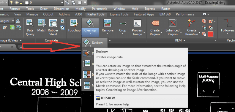
Selecting Deskew in Autodesk Raster Design (source)
Even with the advanced editing options in Raster Design, there will always be the need for manual fine-tuning. To do this, use the “Touchup” tool to manually add or take away sections of the inserted image. The use of the tool will be similar to the tools used in Microsoft Paint, so if you’ve ever had the chance to play around with that program, you’ll have an easy time using Touchup. The different settings of the tool are as follows:
- Color: switch the color of the Touchup tool from black to white or vice versa by clicking “Toggle drawing color”
- Shape and Angle: you can control the shape of the brush used by the Touchup tool by playing around with the options on the left of the toolbar. You can change the angle of the brush as well.
- Size: The fourth option from the left of the Touchup toolbar controls the size of the brush.
Once you’ve done your edits, exit the tool by using the buttons on its toolbar. You can choose “Cancel” to exit without executing the changes you made or Ok to exit and push through with the edits.
Converting to Vector
What truly makes Raster Design such a useful add-on is its ability to convert pixelated lines into vectorized, AutoCAD ready objects, this process is sometimes referred to as ‘Object Recognition‘. Click on the “Vectorize & Recognize Text” button on the Ribbon Tab and then click the “Primitives” button. The drop-down menu will have options to recognize lines, polylines, rectangles, circles, and arcs.
Align your cursor with the line or lines you wish to convert into vector objects and if the object is recognized by Raster Design, dashes will appear on it along with a yellow arrow. Accept the recognized line by pressing Enter and the program will turn it into a vector AutoCAD line while erasing the original pixel line. Clean up any remaining pixels with the Touchup tool. Sometimes you’ll find that lines recognized and converted by this tool might not always meet at corners as accurately as you’d like. Remedy this by using the Fillet tool with a radius of zero.
After editing all the lines, you might want to convert them back into raster image lines to match with the rest of the remaining image. Do this by selecting the vector lines, right-clicking on them, and then selecting “Merge Vector to Raster Image”.
Managing the Embedded Image
When you’re ready with the final image, you might want to embed the image onto the file.
By default, AutoCAD inserts images into its files as references. That is, if you send over the file to a different machine without sending over the separate reference image, the file won’t open accurately. The workaround is embedding the image.
Locate the “Insert & Write” panel on the Ribbon and click on “Embed”. It’s that easy to embed the image into your drawing.

Запустите Автокад. Введите OPTIONS в командной строке и перейдите на вкладку Files. Разверните путь поиска файлов поддержки и добавьте следующие пути, выбрав номер версии установленного Raster Design: C:program filesautodeskautocad raster design 20xx.
Откройте окно «Параметры», введя ОПЦИИ в командной строке или нажав кнопку «Параметры» в меню приложения AutoCAD в левом верхнем углу, щелкните вкладку «Отображение», а затем в разделе «Элементы макета» установите флажок «Отображать вкладки «Макет» и «Модель». а затем нажмите кнопку ОК.
Как вставить растровое изображение в AutoCAD?
Привязка файлов изображений к DWG в Autocad
- После того, как файл изображения открыт в Paint> на клавиатуре «Ctrl + A» вместе (сочетание клавиш «Выбрать все»)> затем нажмите «Ctrl + C» (сочетание клавиш для копирования в буфер обмена)
- Откройте файл Autocad, в который нужно вставить изображение.
- В командной строке введите PASTESPEC > нажмите ENTER.
- Появится диалоговое окно > выберите «Рисунок кисти» > нажмите «ОК».
Включен ли растровый дизайн в AutoCAD 2020?
Теперь входит в состав AutoCAD
В набор инструментов AutoCAD Raster Design добавлены инструменты преобразования растровых изображений в векторные, помогающие преобразовывать растровые изображения в объекты DWG™. Редактируйте отсканированные чертежи в знакомой среде AutoCAD. Удаление пятен, смещение, зеркальное отражение и ретушь ваших изображений. Используйте стандартные команды AutoCAD для растровых областей и примитивов.
Что такое AutoCAD Designer?
Чертежи AutoCAD специализируются на создании моделей автоматизированного проектирования (САПР) с использованием программного обеспечения Autodesk AutoCAD. Эти высококвалифицированные чертежники работают с архитекторами и инженерами над проектированием и созданием 2D и 3D компьютерных моделей зданий и деталей машин по чертежам или с нуля.
Какое определение для raster?
: шаблон сканирования (как для электронного луча в электронно-лучевой трубке), при котором область сканируется из стороны в сторону линиями сверху вниз, а также: шаблон из близко расположенных рядов точек, формирующих изображение (как на электронно-лучевая трубка телевизора или компьютерного дисплея)
Что такое вкладка «Макет» в AutoCAD?
Компоновка — это двухмерная рабочая среда для создания чертежных листов. … Вы можете получить доступ к одному или нескольким макетам на вкладках, расположенных в левом нижнем углу области рисования справа от вкладки «Модель».
Как добавить вкладку в AutoCAD?
Создать вкладку ленты
- На вкладке «Настройка» «Настройки в щелкните значок плюса (+) рядом с узлом ленты, чтобы развернуть его.
- Щелкните правой кнопкой мыши «Вкладки» и выберите «Новая вкладка». …
- Щелкните правой кнопкой мыши Новая вкладка. …
- Выберите новую вкладку ленты в древовидном представлении и обновите панель свойств: …
- Нажмите «Применить».
Перейдите в верхнюю часть панели инструментов на вкладке «Управление», нажмите значок «НПИ» и перетащите «Макет» на «Быструю панель инструментов» в верхней части. Он должен появиться после того, как вы закроете окно. Надеюсь, это помогло. Я перенесу это на форум AutoCAD 2017 для получения дополнительной информации.
Как я могу преобразовать JPG в DWG?
Как конвертировать файлы JPG в DWG онлайн?
- Загрузите JPG-файл. Нажмите кнопку «Выбрать файл», чтобы выбрать файл jpg на вашем компьютере. Размер файла JPG не должен превышать 50 Мб.
- Преобразование JPG в DWG. Нажмите кнопку «Конвертировать», чтобы начать конвертацию.
- Загрузите файл DWG. Когда процесс преобразования завершится, вы сможете загрузить файл DWG.
Можно ли связать изображения в AutoCAD?
Правильный способ — прикрепить изображение с относительным путем (или без него, если изображение находится в той же папке). … Идеальный способ: используйте команду etransmit для всех внешних вещей, таких как шрифты, изображения, другие внешние ссылки, таблица стилей печати.. Единственный способ вставить изображение в качестве содержимого в dwg — это вставить его как встроенный объект OLE.
Можно ли импортировать JPEG в AutoCAD?
В диалоговом окне «Выбор файла изображения» выберите имя файла из списка или введите имя файла изображения в поле «Имя файла». Щелкните Открыть. … Выберите «Указать на экране», чтобы использовать указывающее устройство для вставки изображения в нужном месте, масштабе или под нужным углом.
Является ли AutoCAD векторной программой?
В цифровом мире существует два основных типа графических файлов: векторные рисунки и растровые изображения. AutoCAD — это программа, работающая с векторной графикой. Другими словами, когда вы создаете чертеж AutoCAD, вы работаете с определенными типами объектов: дугами, линиями и текстом.
Как открыть векторный файл в AutoCAD?
Adobe Illustrator создает векторные рисунки, которые по умолчанию сохраняются в формате Adobe [AI]. Этот формат нельзя прочитать в AutoCAD®, но вы можете экспортировать в формат файла DWG в Adobe Illustrator. Экспортируемый файл будет иметь следующие характеристики: Формат DWG AutoCAD 2000.
Что такое растровая растровая графика?
Растровая графика, также называемая растровой графикой, тип цифрового изображения, в котором используются крошечные прямоугольные пиксели или элементы изображения, расположенные в виде сетки для представления изображения.
Heading large > KievitPro Regular 23 on 23 pt, 75%
black. Ut enim ad mini mim veniami quis nostrud
exercitation ullam, corpor suscipit laboris Lorem
ipsum etalus siti amet, duis autem conitu secutur
adipscing elitsef diam eiusmod magnus. Etion
ullam, corpor suscipit laboris Lorem ipsum etalus
siti amet, duis autem conitu secutur adipscing
elitsef diam eiusmod magnus.
Text heading > KievitPro Bold 8.5 on 10.5 pt, product family color
Body Text > KievitPro Regular 8.5 on 10.5 pt, black. lorem ipsum etalus sit amet,
duis autem consecutur adipscing elit, sef diam nonumy eiusmod tempor incident
ut labore magna aliquam erat volupat. Ut enim ad minimim veniami quis
nostrud exercitation ullam, corpor suscipit laboris nisi ut aliquip ex ea commodo
conseauat. Duis autem vel eum irure etalus in reprehjenderit in volupate velit
ewsse moestai xom consequat.
Text heading
Body Text. Vel illum etalusim eu fugiat nulla pariartur —ignissim qui blandit
praes entl upatum delenit aigue duos etalus et molestais excepturisio toccaecet
cupidat non. Lorem ipsum etalus sit amet, duis autem consecutur adipscing elit,
sef diam nonumy eiusmod te mpor incident ut labore magna aliquam erat.
Text heading
Body text. Lorem ipsum etalus sit amet, duis autem consecutur adipscing elit,
sef diam nonumy eiusmod tempor incident ut labore magna aliquam erat
volupat. Ut enim ad minimim veniami quis nostrud exercitation ullam, corpor
suscipit laboris nisi ut aliquip ex ea commodo conseauat. Duis autem vel eum
irure etalus in reprehjenderit.
Legal text > KievitPro Regular 6 on 8 pt, black — Registered trademarks of Autodesk, Inc., in the USA
and/or other countries. All other product names, brand names, or trademarks belong to their respective
holders. © 2008 Autodesk, Inc. All rights reserved. part number
Image is everything.
AutoCAD
®
Raster Design
Learn More or Purchase
Access specialists worldwide who can provide product expertise, a deep
understanding of your industry, and value that extends beyond your software
purchase. To purchase AutoCAD Raster Design software, contact an Autodesk
Premier Solutions Provider or Autodesk Authorized Reseller. Locate a reseller
near you at www.autodesk.com/reseller.
To learn more about AutoCAD Raster Design, visit
www.autodesk.com/rasterdesign.
Looking for high-resolution aerial and satellite imagery as well as vector data for
your projects? Visit www.autodesk.com/geodata.
Autodesk Learning and Education
From instructor-led or self-paced classes to online training or education
resources, Autodesk oers learning solutions to fit your needs. Get expert
guidance at an Autodesk Authorized Training Center (ATC
®
) site, access learning
tools online or at your local bookstore, and validate your experience with
Autodesk certifications. Learn more at www.autodesk.com/learning.
Autodesk Services and Support
Accelerate return on investment and optimize productivity with innovative
purchase methods, companion products, consulting services, and support from
Autodesk and Autodesk authorized partners. Designed to get you up to speed
and keep you ahead of the competition, these tools help you make the most
of your software purchase—no matter what industry you are in. Learn more at
www.autodesk.com/servicesandsupport.
Autodesk Subscription
Get the benefits of increased productivity, predictable budgeting, and simplified
license management with Autodesk
®
Subscription. You get any new upgrades
of your Autodesk software and any incremental product enhancements, if
these are released during your subscription term. In additon, you get exclusive
license terms available only to Subscription members. A range of community
resources, including web support direct from Autodesk technical experts,
self-paced training, and e-Learning, help extend your skills and make Autodesk
Subscription the best way to optimize your investment. Learn more at
www.autodesk.com/subscription.
Autodesk is committed to sustainability. This brochure is printed on percent postconsumer waste recycled paper.
Autodesk, AutoCAD, Civil D, and Topobase are registered trademarks of Autodesk, Inc., and/or its subsidiaries
and/or aliates in the USA and/or other countries. All other brand names, product names, or trademarks belong
to their respective holders. Autodesk reserves the right to alter product oerings and specifications at any time
without notice, and is not responsible for typographical or graphical errors that may appear in this document.
© Autodesk, Inc. All rights reserved.
When our customers bring in their old drawings
that might have been sitting in a drawer for
years, it’s safe to say that the quality of the
drawings may have degraded from age, water
damage, or just plain old dirt. Scans that result from
such damaged drawings aren’t the highest quality;
however, with the powerful suite of tools in Raster
Design, including rubbersheeting, despeckling,
and others, we can massage the data and make it
accurately convey the design intent once again.
— Michael C. Johnson
CEO
Advanced Career Development
Make the most of rasterized scanned drawings,
maps, aerial photos, satellite imagery, and digital
elevation models. Get more out of your raster data
with AutoCAD
®
Raster Design software.
Use AutoCAD Raster Design software with
AutoCAD
®
, AutoCAD
®
Architecture, AutoCAD
®
Civil, AutoCAD
®
Civil D
®
, AutoCAD
®
Electrical,
AutoCAD
®
Map D, AutoCAD
®
Mechanical,
AutoCAD
®
MEP, AutoCAD
®
P&ID, and Autodesk
®
Topobase™ software to unlock and extend
the value of existing design information.
Helping design professionals across a broad range of
industries—civil; GIS/mapping; mechanical, electrical, and
plumbing (MEP); architectural; and manufacturing.
Designs Enhanced
AutoCAD Raster Design enables you to work in an
AutoCAD environment, significantly reducing the
need to purchase and learn multiple applications.
Extend the Value of Existing Information
Unlock and make the most of existing scanned
engineering drawings, plans, and maps by using
them in current projects. You can save redrafting
time with powerful raster editing and raster-to-
vector conversion tools.
Use Industry-Standard Image Formats
AutoCAD Raster Design supports numerous image
formats so designers can easily integrate and use
imagery within their projects. Supported image
formats include MrSID,
®
ECW, and JPEG ,
DigitalGlobe
®
Quickbird TIFF, Landsat FAST-LA
format multispectral imagery, and the National
Imagery Transmission Format (NITF), which is an
important tool for the U.S. Department of Defense
and the federal intelligence community.
Other supported formats include the following:
BMP CALS DEM
DOQ ESRI GRID FLIC
GeoSPOT GeoTIFF GIF
IG JPEG/JFIF DTED
PCX PICT PNG
RLC TGA TIFF
Clean Raster Drawings and Images
Improve usability and legibility of scanned drawings
with powerful image cleanup tools. Despeckle
removes stray pixels that result from scanning dirty
or faded drawings or blueprints. Deskew corrects
drawings that were crooked as they were fed through
a scanner. Bias corrects distortion in an image’s aspect
ratio. Mirror can correct transparencies that have
been scanned upside down. By using these and other
tools, you can reduce the time and eort necessary
to clean up scanned drawings and maps while better
maintaining your image archives.
Enhance Images with Intuitive
Image-Processing Tools
Several image-processing features are available to help
designers get the most from existing imagery. The
histogram feature includes functions to equalize images,
adjust brightness and contrast, convert grayscale or
color images to bitonal images, and perform nonlinear
tonal adjustments. The convolve feature has smoothing
filters to reduce ruggedness and noise as well as
sharpening filters to make dierences in shading more
distinct. The invert feature reverses the light and dark
shades of binary, color, and grayscale images. These and
“While we are working
to create digital versions
of our older paper maps,
we use Raster Design
to edit and maintain
scanned maps digitally.
The software helps us
maintain our existing maps
and lets us easily find and
use our raster assets.”
— Greg Ammon
Water GIS Systems Manager
Los Angeles Department of
Water and Power
Perform raster drawing cleanup, editing and manipulation,
raster-to-vector conversion, and image processing while
working with a breadth of imagery.
Approvals Accelerated
other image-processing features in AutoCAD Raster
Design can help improve the appearance of existing
images, so you can get the full benefit from your
investment in imagery.
Convert Raster Data to Vector
Do you want to be able to use scanned drawings and
map content without having to redraft? Would you
like to convert raster lines, arcs, and text to vector
for use in AutoCAD-based products as part of your
drawing, model, or design? With vectorization tools in
AutoCAD Raster Design, you can interactively convert
raster to vector to accelerate project turnarounds and
improve eciency.
Use Optical Character Recognition
Recognize machine and hand-printed text and
tables on raster images to create AutoCAD text
or multiline text (mtext) automatically. Use
interactive verification to correct results with
dictionary matching. Save manual data entry
time and improve accuracy when converting
scanned documents with a lot of text.
Improve Decision Making
Get projects approved faster by creating drawings
and presenting proposals that integrate information-
rich plans, maps, aerial photos, and other forms
of imagery that enhance communication and
understanding of your design intent.
When used with AutoCAD Map D-based software,
AutoCAD Raster Design provides additional
functionality so you can better utilize geospatial
imagery to create color elevation representations
directly from DEM, DTED, and ESRI
®
GRID raster
files. Visualize the slope and aspect information
you need to help make better design and policy
decisions. Show vegetation, land cover, and
environmental information using readily available
multispectral satellite imagery.
Enhance, Preserve, and Maintain Valuable
Raster Assets
AutoCAD Raster Design software enables you to
easily clean up, edit, enhance, and maintain your
archive of scanned drawings and plans with image
cleanup, processing, and hybrid editing tools in a
familiar AutoCAD environment.
Incorporate widely available geospatial raster data that can be used to visualize information such as land cover.
Data used in
image from USGS National Land Cover Database
.
Use correlation tools such as the unlimited point
rubbersheet function to align aerial photos to drawings.
Accurately vectorize partial or entire scanned sheets
using the semiautomatic and interactive raster-to-vector
conversion utilities.