-
Contents
-
Table of Contents
-
Bookmarks
Quick Links
®
Relion
670 series
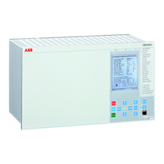
Transformer protection RET670 ANSI
Pre-configured
Product Guide
Related Manuals for ABB RET670
Summary of Contents for ABB RET670
-
Page 1
® Relion 670 series Transformer protection RET670 ANSI Pre-configured Product Guide… -
Page 2: Table Of Contents
20. Ordering……………..83 Disclaimer © Copyright 2012 ABB. All rights reserved. Trademarks ABB and Relion are registered trademarks of ABB Group. All other brand or product names mentioned in this document may be trademarks or registered trademarks of their respective holders.
-
Page 3: Application
IED the ideal solution operation for post-fault disturbance analysis. even for the most demanding applications. Since RET670 has very low requirements on the main Breaker failure protection for each transformer CTs, no interposing CTs are required.It is suitable…
-
Page 4
Transformer protection RET670 ANSI 1MRK 504 118-BUS A Pre-configured Product version: 1.2 The wide application flexibility makes this product are available as template in the graphical an excellent choice for both new installations and configuration tool. An alternative for the refurbishment of existing installations. -
Page 5
Transformer protection RET670 ANSI 1MRK 504 118-BUS A Pre-configured Product version: 1.2 RET 670 50BF TRIP BKR1 WDG1 WDG2 51P/67P TRIP BKR3 50BF 51N/67N VT’s from WDG 2 side of XFRM ANSI10000087-2-en.vsd ANSI10000087 V2 EN Figure 1. A typical protection application for a two winding transformer in single breaker arrangements is shown on the figure. -
Page 6
Transformer protection RET670 ANSI 1MRK 504 118-BUS A Pre-configured Product version: 1.2 Trip from 50-BF1, 50-BF2 50/51N 50BF2 50BF1 TRIP BKR1 94/86 50/51P BKR1 BKR2 50/51G TRIP BKR2 94/86 WDG1 WDG2 50/51G 50/51P 50BF4 TRIP BKR3 94/86 BKR4 BKR3 50BF3… -
Page 7
Transformer protection RET670 ANSI 1MRK 504 118-BUS A Pre-configured Product version: 1.2 Trip from 50-BF1, 50-BF2 50/51P 50BF5 TRIP BKR5 94/86 50/51N 94/86 50BF2 50BF1 TRIP 50/51P BKR1 94/86 94/86 BKR1 BKR2 WDG3 TRIP BKR2 94/86 WDG1 WDG2 50/51G 50/51P… -
Page 8: Available Functions
Transformer protection RET670 ANSI 1MRK 504 118-BUS A Pre-configured Product version: 1.2 2. Available functions Main protection functions = number of basic instances 3-A03 = optional function included in packages A03 (refer to ordering details) IEC 61850 ANSI Function description…
-
Page 9: Current Protection
Transformer protection RET670 ANSI 1MRK 504 118-BUS A Pre-configured Product version: 1.2 Back-up protection functions IEC 61850 ANSI Function description Transformer Current protection OC4PTOC 51_67 Four step phase overcurrent protection EF4PTOC 51N_67 Four step residual overcurrent protection NS4PTOC 46I2 Four step directional negative phase sequence…
-
Page 10: Secondary System Supervision
Transformer protection RET670 ANSI 1MRK 504 118-BUS A Pre-configured Product version: 1.2 Control and monitoring functions IEC 61850 ANSI Function description Transformer Control SESRSYN Synchrocheck, energizing check and synchronizing APC30 Apparatus control for up to 6 bays, max 30 apparatuses (6CBs) incl.
-
Page 11: Monitoring
Transformer protection RET670 ANSI 1MRK 504 118-BUS A Pre-configured Product version: 1.2 IEC 61850 ANSI Function description Transformer Configuration logic blocks 40-280 40-280 40-280 Fixed signal function blocks B16I Boolean 16 to Integer conversion B16IFCVI Boolean 16 to Integer conversion with Logic Node…
-
Page 12: Remote
Transformer protection RET670 ANSI 1MRK 504 118-BUS A Pre-configured Product version: 1.2 Designed to communicate IEC 61850 ANSI Function description Transformer Station communication SPA communication protocol LON communication protocol IEC60870-5-103 communication 20/1 20/1 20/1 protocol Operation selection between SPA and IEC60870-5-103 for SLM DNP3.0 for TCP/IP and EIA-485…
-
Page 13: Basic Ied Functions
Transformer protection RET670 ANSI 1MRK 504 118-BUS A Pre-configured Product version: 1.2 Basic IED functions IEC 61850 Function description Basic functions included in all products IntErrorSig Self supervision with internal event list TIME Time and synchronization error TimeSynch Time synchronization…
-
Page 14
Transformer protection RET670 ANSI 1MRK 504 118-BUS A Pre-configured Product version: 1.2 3. Differential protection The low-impedance function is a percentage biased function with an additional zero sequence current Transformer differential protection T2WPDIF/ directional comparison criterion. This gives excellent T3WPDIF (87T) sensitivity and stability during through faults. -
Page 15
Transformer protection RET670 ANSI 1MRK 504 118-BUS A Pre-configured Product version: 1.2 The thermal overload protection estimates the Four step residual overcurrent protection, zero internal heat content of the transformer/generator sequence and negative sequence direction (temperature) continuously. This estimation is made… -
Page 16
Transformer protection RET670 ANSI 1MRK 504 118-BUS A Pre-configured Product version: 1.2 5. Voltage protection Overexcitation protection OEXPVPH (24) Two step undervoltage protection UV2PTUV (27) When the laminated core of a power transformer or Undervoltages can occur in the power system generator is subjected to a magnetic flux density during faults or abnormal conditions. -
Page 17
Transformer protection RET670 ANSI 1MRK 504 118-BUS A Pre-configured Product version: 1.2 generating plant, generator governor problems can restraining facility is available as well. At too low also cause over frequency. polarizing voltage the overcurrent feature can be either blocked, made non directional or ordered to… -
Page 18
Transformer protection RET670 ANSI 1MRK 504 118-BUS A Pre-configured Product version: 1.2 The fuse failure supervision function basically has SESRSYN (25) function includes a built-in voltage three different algorithms, negative sequence and selection scheme for double bus and breaker-and-a- zero sequence based algorithms and an additional half or ring busbar arrangements. -
Page 19
Transformer protection RET670 ANSI 1MRK 504 118-BUS A Pre-configured Product version: 1.2 with enhanced security, the command is processed transformer so that for example, the voltage control and the resulting position is supervised. can be blocked if the power reverses etc. -
Page 20: Local
Transformer protection RET670 ANSI 1MRK 504 118-BUS A Pre-configured Product version: 1.2 Single command, 16 signals Supervision of mA input signals The IEDs can receive commands either from a The main purpose of the function is to measure and substation automation system or from the local process signals from different measuring HMI.
-
Page 21: Local
Transformer protection RET670 ANSI 1MRK 504 118-BUS A Pre-configured Product version: 1.2 signals from start of pre-fault time to the end of The event recorder logs all selected binary input post-fault time will be included in the recording. signals connected to the Disturbance report function.
-
Page 22: Human Machine Interface
Transformer protection RET670 ANSI 1MRK 504 118-BUS A Pre-configured Product version: 1.2 before the trigger instant can be saved in the be used as conditions in the configurable logic or disturbance file. for alarming purpose. The disturbance recorder information for up to 100 12.
-
Page 23: Station Communication
ABB IED’s and the new IED 670. SPA communication protocol A single glass or plastic port is provided for the ABB SPA protocol. This allows extensions of simple substation automation systems but the main use is IEC07000077 V1 EN for Substation Monitoring Systems SMS.
-
Page 24: Remote Communication
Transformer protection RET670 ANSI 1MRK 504 118-BUS A Pre-configured Product version: 1.2 as status of primary switchgear apparatus or Multiple command and transmit intertripping signals to the remote IED. An IED can When 670 IED’s are used in Substation Automation communicate with up to 4 remote IEDs.
-
Page 25: Remote
Transformer protection RET670 ANSI 1MRK 504 118-BUS A Pre-configured Product version: 1.2 evaluation of operation of the IED and for all Line data communication module LDCM associated electrical circuits. Each module has one optical port, one for each remote end to which the IED communicates.
-
Page 26
Transformer protection RET670 ANSI 1MRK 504 118-BUS A Pre-configured Product version: 1.2 resistor, is available in a single phase unit and a Layout and dimensions three phase unit. Both are mounted on a 1/1 19 Dimensions inch apparatus plate with compression type terminals. -
Page 27
Transformer protection RET670 ANSI 1MRK 504 118-BUS A Pre-configured Product version: 1.2 Case size 6U, 1/2 x 19” 10.47 8.81 7.92 9.53 9.96 8.10 6U, 3/4 x 19” 10.47 13.23 7.92 9.53 9.96 12.52 6U, 1/1 x 19” 10.47 17.65 7.92… -
Page 28: Connection Diagrams
Transformer protection RET670 ANSI 1MRK 504 118-BUS A Pre-configured Product version: 1.2 18. Connection diagrams Table 1. Designations for 1/2 x 19” casing with 1 TRM slot Module Rear Positions BIM, BOM, SOM, IOM or X31 and X32 etc. to X51…
-
Page 29
Transformer protection RET670 ANSI 1MRK 504 118-BUS A Pre-configured Product version: 1.2 Table 2. Designations for 3/4 x 19” casing with 1 TRM slot Module Rear Positions BIM, BOM, SOM, IOM or X31 and X32 etc. to X101 and X102… -
Page 30
Transformer protection RET670 ANSI 1MRK 504 118-BUS A Pre-configured Product version: 1.2 Table 3. Designations for 1/1 x 19” casing with 2 TRM slots Module Rear Positions BIM, BOM, SOM, X31 and X32 etc. to X131 IOM or MIM and X132… -
Page 31
Transformer protection RET670 ANSI 1MRK 504 118-BUS A Pre-configured Product version: 1.2 1MRK002802-AB-10-670-1.2-PG-ANSI V1 EN Figure 8. Transformer input module (TRM) ■ Indicates high polarity. See table Note that internal polarity can be adjusted by setting of analog input CT neutral direction and/or on SMAI pre- processing function blocks. -
Page 32
Transformer protection RET670 ANSI 1MRK 504 118-BUS A Pre-configured Product version: 1.2 1MRK002802-AB-7-670-1.2-PG-ANSI V1 EN Figure 9. Power supply module (PSM) -
Page 33
Transformer protection RET670 ANSI 1MRK 504 118-BUS A Pre-configured Product version: 1.2 1MRK002802-AB-11-670-1.2-PG-ANSI V1 EN Figure 10. Binary input module (BIM). Input contacts named XA corresponds to rear position X31, X41, etc. and input contacts named XB to rear position X32, X42, etc. -
Page 34
Transformer protection RET670 ANSI 1MRK 504 118-BUS A Pre-configured Product version: 1.2 1MRK002802-AB-8-670-1.2-PG-ANSI V1 EN Figure 15. IED with basic functionality communication interfaces… -
Page 35
Transformer protection RET670 ANSI 1MRK 504 118-BUS A Pre-configured Product version: 1.2 IED670 BUS A BUS B 87B-TRIP 189-OPEN 189b BLOCK LV 51P 189-CL 189a BFI 3PH 289b 289-OPEN 289a 289-CL SUDDEN PRESSURE TRIP OIL TEMP TRIP TRM1:1-3 WIND TEMP TRIP… -
Page 36
Transformer protection RET670 ANSI 1MRK 504 118-BUS A Pre-configured Product version: 1.2 Figure 16. Typical connection diagram for two winding transformer in a single breaker arrangement. Note! Including IO for control option. -
Page 37
Transformer protection RET670 ANSI 1MRK 504 118-BUS A Pre-configured Product version: 1.2 IED670 BUS A 189-OPEN 189b 87B-TRIP 189-CL 189a 6289-OPEN 6289b BLOCK LV 51P 6289-CL 6289a 6289 BFI 3PH TRM1:1-3 SUDDEN TRM1:4-6 TO MAIN 2 PRESSURE TRIP OIL TEMP TRIP… -
Page 38
Transformer protection RET670 ANSI 1MRK 504 118-BUS A Pre-configured Product version: 1.2 BUS A IED670 BUS B 87B-TRIP 189-OPEN 189b 189-CL 189a BLOCK LV 51P 289-OPEN 289b 289-CL 289a BFI 3PH TRM1:1-3 SUDDEN PRESSURE TRIP TO MAIN 2 OIL TEMP TRIP… -
Page 39
Transformer protection RET670 ANSI 1MRK 504 118-BUS A Pre-configured Product version: 1.2 Figure 18. Typical connection diagram for three winding transformer in a single breaker arrangement. Note! Including IO for control option. -
Page 40
Transformer protection RET670 ANSI 1MRK 504 118-BUS A Pre-configured Product version: 1.2 BUS A IED670 TO SECOND BAY 189-OPEN 189b 189-CL 189a 6289-OPEN 6289b 6289-CL 6289a 87B-TRIP 6289 TRM1:1-3 BLOCK LV 51P TRM1:4-6 BFI 3PH TO MAIN 2 TO MAIN 2… -
Page 41: Technical Data
Transformer protection RET670 ANSI 1MRK 504 118-BUS A Pre-configured Product version: 1.2 19. Technical data General Definitions Reference value The specified value of an influencing factor to which are referred the characteristics of the equipment Nominal range The range of values of an influencing quantity (factor) within which, under specified conditions, the…
-
Page 42
Transformer protection RET670 ANSI 1MRK 504 118-BUS A Pre-configured Product version: 1.2 Table 6. TRM — Energizing quantities, rated values and limits for measuring transformer modules Quantity Rated value Nominal range Current = 1 or 5 A (0-1.8) × I… -
Page 43
Transformer protection RET670 ANSI 1MRK 504 118-BUS A Pre-configured Product version: 1.2 Auxiliary DC voltage Table 9. PSM — Power supply module Quantity Rated value Nominal range Auxiliary dc voltage, EL (input) EL = (24 — 60) V EL ± 20% EL = (90 — 250) V EL ±… -
Page 44
Transformer protection RET670 ANSI 1MRK 504 118-BUS A Pre-configured Product version: 1.2 Table 11. BIM — Binary input module with enhanced pulse counting capabilities Quantity Rated value Nominal range Binary inputs DC voltage, RL 24/30 V RL ± 20% 48/60 V RL ±… -
Page 45
Transformer protection RET670 ANSI 1MRK 504 118-BUS A Pre-configured Product version: 1.2 Table 13. IOM — Binary input/output module contact data (reference standard: IEC 61810-2) Function or quantity Trip and signal relays Fast signal relays (parallel reed relay) Binary outputs… -
Page 46
Transformer protection RET670 ANSI 1MRK 504 118-BUS A Pre-configured Product version: 1.2 Table 14. SOM — Static Output Module (reference standard: IEC 61810-2): Static binary outputs Function of quantity Static binary output trip Rated voltage 48 — 60 VDC 110 — 250 VDC… -
Page 47
Transformer protection RET670 ANSI 1MRK 504 118-BUS A Pre-configured Product version: 1.2 Table 15. SOM — Static Output module data (reference standard: IEC 61810-2): Electromechanical relay outputs Function of quantity Trip and signal relays Max system voltage 250V AC/DC Number of outputs… -
Page 48
Transformer protection RET670 ANSI 1MRK 504 118-BUS A Pre-configured Product version: 1.2 Influencing factors Table 17. Temperature and humidity influence Parameter Reference value Nominal range Influence Ambient temperature, +20 °C -10 °C to +55 °C 0.02% /°C operate value Relative humidity… -
Page 49
Transformer protection RET670 ANSI 1MRK 504 118-BUS A Pre-configured Product version: 1.2 Type tests according to standards Table 20. Electromagnetic compatibility Test Type test values Reference standards 1 MHz Oscillatory burst disturbance 2.5 kV IEC 60255-22-1 100 kHz slow damped oscillatory wave immunity 2.5 kV… -
Page 50
Transformer protection RET670 ANSI 1MRK 504 118-BUS A Pre-configured Product version: 1.2 Table 22. Environmental tests Test Type test value Reference standard Cold test Test Ad for 16 h at -25°C IEC 60068-2-1 Storage test Test Ad for 16 h at -40°C… -
Page 51
Transformer protection RET670 ANSI 1MRK 504 118-BUS A Pre-configured Product version: 1.2 Differential protection Table 25. Transformer differential protection T2WPDIF, T3WPDIF (87T) Function Range or value Accuracy Operating characteristic Adaptable ± 1.0% of In for I < In ± 1.0% of In for I > In Reset ratio >95%… -
Page 52
Transformer protection RET670 ANSI 1MRK 504 118-BUS A Pre-configured Product version: 1.2 Table 26. Restricted earth fault protection, low impedance REFPDIF (87N) Function Range or value Accuracy Operate characteristic Adaptable ± 1.0% of I for I < I ± 1.0% of I for I > I Reset ratio >95%… -
Page 53
Transformer protection RET670 ANSI 1MRK 504 118-BUS A Pre-configured Product version: 1.2 Current protection Table 27. Four step phase overcurrent protection OC4PTOC (51/67) Function Setting range Accuracy Operate current (1-2500)% of lBase ± 1.0% of I at I ≤ I ±… -
Page 54
Transformer protection RET670 ANSI 1MRK 504 118-BUS A Pre-configured Product version: 1.2 Table 28. Four step residual overcurrent protection EF4PTOC (51N/67N) Function Range or value Accuracy lBase Operate current (1-2500)% of ± 1.0% of I at I £ I ± 1.0% of I at I > I Reset ratio >… -
Page 55
Transformer protection RET670 ANSI 1MRK 504 118-BUS A Pre-configured Product version: 1.2 Table 29. Four step negative sequence overcurrent protection NS4PTOC (46I2) Function Range or value Accuracy lBase Operate value, negative (1-2500)% of ± 1.0% of I at I £ I sequence current, step 1-4 ±… -
Page 56
Transformer protection RET670 ANSI 1MRK 504 118-BUS A Pre-configured Product version: 1.2 Table 30. Thermal overload protection, two time constants TRPTTR (49) Function Range or value Accuracy IBase Base current 1 and 2 (30–250)% of ± 1.0% of I Operate time: = load current before overload IEC 60255–8, class 5 + 200 ms… -
Page 57
Transformer protection RET670 ANSI 1MRK 504 118-BUS A Pre-configured Product version: 1.2 Voltage protection Table 33. Two step undervoltage protection UV2PTUV (27) Function Range or value Accuracy Operate voltage, low and high step (1–100)% of VBase ± 0.5% of V Absolute hysteresis (0–100)% of… -
Page 58
Transformer protection RET670 ANSI 1MRK 504 118-BUS A Pre-configured Product version: 1.2 Table 35. Two step residual overvoltage protection ROV2PTOV (59N) Function Range or value Accuracy VBase Operate voltage, low and high step (1-200)% of ± 0.5% of V at V < V ±… -
Page 59
Transformer protection RET670 ANSI 1MRK 504 118-BUS A Pre-configured Product version: 1.2 Table 37. Loss of voltage check LOVPTUV (27) Function Range or value Accuracy Operate voltage (0–100)% of VBase ± 0.5% of V Pulse timer (0.050–60.000) s ± 0.5% ± 10 ms Timers (0.000–60.000) s… -
Page 60
Transformer protection RET670 ANSI 1MRK 504 118-BUS A Pre-configured Product version: 1.2 Frequency protection Table 38. Underfrequency protection SAPTUF (81) Function Range or value Accuracy Operate value, pickup function (35.00-75.00) Hz ± 2.0 mHz Operate time, pickup function 100 ms typically… -
Page 61
Transformer protection RET670 ANSI 1MRK 504 118-BUS A Pre-configured Product version: 1.2 Table 39. Overfrequency protection SAPTOF (81) Function Range or value Accuracy Operate value, pickup function (35.00-75.00) Hz ± 2.0 mHz at symmetrical three- phase voltage Operate time, pickup function 100 ms typically at f -0.5 Hz to f… -
Page 62
Transformer protection RET670 ANSI 1MRK 504 118-BUS A Pre-configured Product version: 1.2 Multipurpose protection Table 41. General current and voltage protection CVGAPC Function Range or value Accuracy Measuring current input Phase A, Phase B, Phase C, PosSeq, NegSeq, 3*ZeroSeq, MaxPh, MinPh,… -
Page 63
Transformer protection RET670 ANSI 1MRK 504 118-BUS A Pre-configured Product version: 1.2 Table 41. General current and voltage protection CVGAPC , continued Function Range or value Accuracy Operate time, pickup overvoltage 25 ms typically at 0 to 2 x V… -
Page 64
Transformer protection RET670 ANSI 1MRK 504 118-BUS A Pre-configured Product version: 1.2 Secondary system supervision Table 42. Current circuit supervision CCSRDIF (87) Function Range or value Accuracy Operate current (5-200)% of I ± 10.0% of I at I £ I ±… -
Page 65
Transformer protection RET670 ANSI 1MRK 504 118-BUS A Pre-configured Product version: 1.2 Control Table 44. Synchronizing, synchronism check and energizing check SESRSYN (25) Function Range or value Accuracy Phase shift, j (-180 to 180) degrees line Voltage ratio, V (0.40-25.000) % of… -
Page 66: Logic Smpptrc
Transformer protection RET670 ANSI 1MRK 504 118-BUS A Pre-configured Product version: 1.2 Logic Table 45. Tripping logic SMPPTRC (94) Function Range or value Accuracy Trip action 3-ph, 1/3-ph, 1/2/3-ph Minimum trip pulse length (0.000-60.000) s ± 0.5% ± 10 ms Timers (0.000-60.000) s…
-
Page 67
Transformer protection RET670 ANSI 1MRK 504 118-BUS A Pre-configured Product version: 1.2 Monitoring Table 47. Measurements CVMMXN Function Range or value Accuracy Frequency (0.95-1.05) × f ± 2.0 mHz Connected current (0.2-4.0) × I ± 0.5% of I at I £ I ±… -
Page 68
Transformer protection RET670 ANSI 1MRK 504 118-BUS A Pre-configured Product version: 1.2 Table 50. Disturbance report DRPRDRE Function Range or value Accuracy Pre-fault time (0.05–9.90) s Post-fault time (0.1–10.0) s Limit time (0.5–10.0) s Maximum number of recordings 100, first in — first out… -
Page 69
Transformer protection RET670 ANSI 1MRK 504 118-BUS A Pre-configured Product version: 1.2 Table 53. Event recorder Function Value Buffer capacity Maximum number of events in disturbance report Maximum number of disturbance reports Resolution 1 ms Accuracy Depending on time synchronizing Table 54. -
Page 70
Transformer protection RET670 ANSI 1MRK 504 118-BUS A Pre-configured Product version: 1.2 Metering Table 56. Pulse counter PCGGIO Function Setting range Accuracy Input frequency See Binary Input Module (BIM) Cycle time for report of counter (1–3600) s value Table 57. Energy metering ETPMMTR… -
Page 71
Transformer protection RET670 ANSI 1MRK 504 118-BUS A Pre-configured Product version: 1.2 Station communication Table 58. IEC 61850-8-1 communication protocol Function Value Protocol IEC 61850-8-1 Communication speed for the IEDs 100BASE-FX Table 59. LON communication protocol Function Value Protocol Communication speed 1.25 Mbit/s… -
Page 72
Transformer protection RET670 ANSI 1MRK 504 118-BUS A Pre-configured Product version: 1.2 Table 63. SLM – SPA/IEC 60870-5-103/DNP3 port Quantity Range or value Optical connector Glass fiber: type ST Plastic fiber: type HFBR snap-in Fiber, optical budget Glass fiber: 11 dB (3000ft/1000 m typically *) -
Page 73: Remote
Transformer protection RET670 ANSI 1MRK 504 118-BUS A Pre-configured Product version: 1.2 Remote communication Table 67. Line data communication module Characteristic Range or value Type of LDCM Short range (SR) Medium range (MR) Long range (LR) Type of fiber Graded-index Singlemode 9/125 µm…
-
Page 74
Transformer protection RET670 ANSI 1MRK 504 118-BUS A Pre-configured Product version: 1.2 Hardware Table 68. Case Material Steel sheet Front plate Steel sheet profile with cut-out for HMI Surface treatment Aluzink preplated steel Finish Light grey (RAL 7035) Table 69. Water and dust protection level according to IEC 60529… -
Page 75
Transformer protection RET670 ANSI 1MRK 504 118-BUS A Pre-configured Product version: 1.2 Basic IED functions Table 73. Self supervision with internal event list Data Value Recording manner Continuous, event controlled List size 1000 events, first in-first out Table 74. Time synchronization, time tagging… -
Page 76
Transformer protection RET670 ANSI 1MRK 504 118-BUS A Pre-configured Product version: 1.2 Table 77. IRIG-B Quantity Rated value Number of channels IRIG-B Number of channels PPS Electrical connector: Electrical connector IRIG-B Pulse-width modulated 5 Vpp Amplitude modulated – low level 1-3 Vpp –… -
Page 77
Transformer protection RET670 ANSI 1MRK 504 118-BUS A Pre-configured Product version: 1.2 Inverse characteristic Table 78. ANSI Inverse time characteristics Function Range or value Accuracy Operating characteristic: td = (0.05-999) in steps of 0.01 unless otherwise stated æ ö ç… -
Page 78
Transformer protection RET670 ANSI 1MRK 504 118-BUS A Pre-configured Product version: 1.2 Table 79. IEC Inverse time characteristics Function Range or value Accuracy Operating characteristic: td = (0.05-999) in steps of 0.01 æ ö ç ÷ × ç ÷ è… -
Page 79
Transformer protection RET670 ANSI 1MRK 504 118-BUS A Pre-configured Product version: 1.2 Table 80. RI and RD type inverse time characteristics Function Range or value Accuracy RI type inverse characteristic td = (0.05-999) in steps of 0.01 IEC 60255-3, class 5 + 40 ms ×… -
Page 80
Transformer protection RET670 ANSI 1MRK 504 118-BUS A Pre-configured Product version: 1.2 Table 81. Inverse time characteristics for overvoltage protection Function Range or value Accuracy Type A curve: td = (0.05-1.10) in steps of 0.01 unless Class 5 +40 ms otherwise stated æ… -
Page 81
Transformer protection RET670 ANSI 1MRK 504 118-BUS A Pre-configured Product version: 1.2 Table 82. Inverse time characteristics for undervoltage protection Function Range or value Accuracy Type A curve: td = (0.05-1.10) in steps of 0.01 unless Class 5 +40 ms otherwise stated æ… -
Page 82
Transformer protection RET670 ANSI 1MRK 504 118-BUS A Pre-configured Product version: 1.2 Table 83. Inverse time characteristics for residual overvoltage protection Function Range or value Accuracy Type A curve: td = (0.05-1.10) in steps Class 5 +40 ms of 0.01 æ… -
Page 83: Ordering
To obtain the complete ordering code, please combine code from the tables, as given in the example below. Example code: RET670*1.2-A30A-A01A02B12C05D01D03E01F02H09-B1-X0-C-B-KA-B3X0-A-ABC-X-XD. Using the code of each position #1-11 specified as RET670*1-2 2-3-4-5-6-7 7-8-9 9 9 9-10 10 10 10 10 10-11 11 11 11 11 11 11-12 12 RET670*…
-
Page 84
Transformer protection RET670 ANSI 1MRK 504 118-BUS A Pre-configured Product version: 1.2 Casing Notes and Rules 1/2 x 19″ case Note: Only for A30A 3/4 x 19″ case 1TRM slot Note: Only for A30A 1/1 x 19″ case 2 TRM slots Note: Only for B30A/B40A Selection for position #5. -
Page 85
Transformer protection RET670 ANSI 1MRK 504 118-BUS A Pre-configured Product version: 1.2 Binary input/output module, mA and time Notes and Rules synchronization boards. Note: 1 BIM and 1 BOM included in A30A, 2 BIM and 1 BOM included in B30A/ B40A. -
Page 86: Remote
Transformer protection RET670 ANSI 1MRK 504 118-BUS A Pre-configured Product version: 1.2 Remote end communication, DNP serial comm. and time Notes and Rules synchronization modules Slot position (rear view) Available slots in 1/2 case with 1 TRM █ █ █…
-
Page 87
Transformer protection RET670 ANSI 1MRK 504 118-BUS A Pre-configured Product version: 1.2 Test switch RHGS 6 Case or RHGS 12 Case with mounted The test system COMBITEST intended for use with RTXP 24 and the on/off switch for dc-supply are the IED 670 products is described in 1MRK 512 ordered separately. -
Page 88
Transformer protection RET670 ANSI 1MRK 504 118-BUS A Pre-configured Product version: 1.2 Configuration and monitoring tools Front connection cable between LCD-HMI and PC Quantity: 1MRK 001 665-CA LED Label special paper A4, 1 pc Quantity: 1MRK 002 038-CA LED Label special paper Letter, 1 pc… -
Page 89
670 series SPA and signal list 1MRK 500 092-WUS IEC 61850 Data objects list for 670 series 1MRK 500 091-WUS Engineering manual 670 series 1MRK 511 256-UUS Communication set-up for Relion 670 series 1MRK 505 260-UEN More information can be found on www.abb.com/substationautomation. -
Page 91
ABB Inc. 3450 Harvester Road Burlington, ON L7N 3W5, Canada Phone Toll Free: 1-800-HELP-365, menu option #8 ABB Mexico S.A. de C.V. Paseo de las Americas No. 31 Lomas Verdes 3a secc. 53125, Naucalpan, Estado De Mexico, MEXICO Phone (+1) 440-585-7804, menu…
- Manuals
- Brands
- ABB Manuals
- Protection Device
- RELION RET670
Manuals and User Guides for ABB RELION RET670. We have 17 ABB RELION RET670 manuals available for free PDF download: Applications Manual, Commissioning Manual, Installation And Commissioning Manual, Operator’s Manual, Product Manual, Installation Manual, Communication Protocol Manual
ABB RELION RET670 Applications Manual (744 pages)
Transformer protection
Brand: ABB
|
Category: Protection Device
|
Size: 10.28 MB
Table of Contents
-
Table of Contents
7
-
Introduction
27
-
This Manual
27
-
Intended Audience
27
-
Product Documentation
28
-
Product Documentation Set
28
-
Document Revision History
29
-
Related Documents
29
-
Document Symbols and Conventions
30
-
Symbols
30
-
Document Conventions
31
-
IEC61850 Edition 1 / Edition 2 Mapping
31
-
-
Application
39
-
General IED Application
39
-
Main Protection Functions
40
-
Back-Up Protection Functions
43
-
Control and Monitoring Functions
46
-
Communication
52
-
Basic IED Functions
55
-
-
Configuration
59
-
Introduction
59
-
Description of Configuration RET670
60
-
Introduction
60
-
Description of Configuration A30
60
-
Description of Configuration B30
61
-
Description of Configuration A40
63
-
Description of Configuration B40
65
-
Description of Configuration A10
67
-
Description of Configuration A25
69
-
-
Analog Inputs
71
-
Introduction
71
-
Setting Guidelines
71
-
Setting of the Phase Reference Channel
71
-
Example
72
-
Setting of Current Channels
72
-
Example 1
72
-
Example 2
73
-
Example 3
74
-
Examples on How to Connect, Configure and Set CT Inputs for most Commonly Used CT Connections
78
-
Example on How to Connect a Star Connected Three-Phase CT Set to the IED
79
-
Example How to Connect Delta Connected Three-Phase CT Set to the IED
82
-
Example How to Connect Single-Phase CT to the IED
84
-
Relationships between Setting Parameter Base Current, CT Rated Primary Current and Minimum Pickup of a Protection IED
85
-
Setting of Voltage Channels
86
-
Example
86
-
Examples How to Connect, Configure and Set VT Inputs for most Commonly Used VT Connections
86
-
Examples on How to Connect a Three Phase-To-Earth Connected VT to the IED
87
-
Example on How to Connect a Phase-To-Phase Connected VT to the IED
89
-
Example on How to Connect an Open Delta VT to the IED for High Impedance Earthed or Unearthed Netwoeks
91
-
Example How to Connect the Open Delta VT to the IED for Low Impedance Earthed or Solidly Earthed Power Systems
92
-
Example on How to Connect a Neutral Point VT to the IED
94
-
-
Local HMI
97
-
Display
98
-
Leds
99
-
Keypad
100
-
Local HMI Functionality
102
-
Protection and Alarm Indication
102
-
Parameter Management
103
-
Front Communication
103
-
-
Differential Protection
105
-
Transformer Differential Protection T2WPDIF and T3WPDIF
105
-
Identification
105
-
Application
105
-
Setting Guidelines
106
-
Restrained and Unrestrained Differential Protection
106
-
Elimination of Zero Sequence Currents
108
-
Inrush Restraint Methods
109
-
Overexcitation Restraint Method
109
-
Cross-Blocking between Phases
109
-
External/Internal Fault Discriminator
110
-
On-Line Compensation for On-Load Tap-Changer Position
111
-
Differential Current Alarm
111
-
Open CT Detection
112
-
Switch Onto Fault Feature
112
-
Setting Example
112
-
Introduction
112
-
Typical Main CT Connections for Transformer Differential Protection
113
-
Application Examples
114
-
Summary and Conclusions
121
-
High Impedance Differential Protection, Single Phase HZPDIF
122
-
Identification
122
-
Application
122
-
The Basics of the High Impedance Principle
123
-
Connection Examples for High Impedance Differential Protection
128
-
Connections for Three-Phase High Impedance Differential Protection
128
-
Connections for 1Ph High Impedance Differential Protection HZPDIF
129
-
Setting Guidelines
130
-
Configuration
130
-
Settings of Protection Function
130
-
T-Feeder Protection
130
-
Autotransformer Differential Protection
132
-
Tertiary Reactor Protection
137
-
Restricted Earth Fault Protection
139
-
Alarm Level Operation
140
-
Low Impedance Restricted Earth Fault Protection REFPDIF
141
-
Identification
141
-
Application
141
-
Transformer Winding, Solidly Earthed
142
-
Transformer Winding, Earthed through Zig-Zag Earthing Transformer
143
-
Autotransformer Winding, Solidly Earthed
143
-
Reactor Winding, Solidly Earthed
144
-
Multi-Breaker Applications
145
-
CT Earthing Direction
146
-
Setting Guidelines
146
-
Setting and Configuration
146
-
Settings
147
-
Additional Security Logic for Differential Protection LDRGFC
147
-
Identification
147
-
Application
148
-
Setting Guidelines
149
-
Advertisement
ABB RELION RET670 Applications Manual (1016 pages)
RELION 670 SERIES Transformer protection Version 2.2 ANSI
Brand: ABB
|
Category: Protection Device
|
Size: 14.18 MB
Table of Contents
-
Table of Contents
7
-
Table of Contents
14
-
Section 1 Introduction
33
-
This Manual
33
-
Intended Audience
33
-
Product Documentation
34
-
Product Documentation Set
34
-
Document Revision History
35
-
Related Documents
36
-
-
Document Symbols and Conventions
36
-
Symbols
36
-
Document Conventions
37
-
-
IEC 61850 Edition 1 / Edition 2 Mapping
38
-
-
Section 2 Application
49
-
General IED Application
49
-
Main Protection Functions
51
-
Back-Up Protection Functions
52
-
Control and Monitoring Functions
54
-
Communication
59
-
Basic IED Functions
62
-
-
Section 3 Configuration
65
-
Description of Configuration RET670
65
-
Introduction
65
-
Description of Configuration A10
65
-
Description of Configuration A25
68
-
Description of Configuration B30
69
-
Description of Configuration B40
72
-
-
-
-
Section 4 Analog Inputs
75
-
Introduction
75
-
Setting Guidelines
75
-
Setting of the Phase Reference Channel
75
-
Example
76
-
-
Setting of Current Channels
76
-
Example 1
77
-
Example 2
77
-
Example 3
78
-
For most Commonly Used CT Connections
81
-
Example on How to Connect a Wye Connected Three-Phase CT Set to the IED
82
-
Example How to Connect Delta Connected Three-Phase CT Set to the IED
87
-
-
Example How to Connect Single-Phase CT to the IED
90
-
Relationships between Setting Parameter Base Current, CT Rated Primary Current and Minimum Pickup of a Protection IED
92
-
Example
93
-
Examples on How to Connect a Three Phase-To-Ground Connected VT to the IED
94
-
Example on How to Connect a Phase-To-Phase Connected VT to the IED
96
-
Example on How to Connect an Open Delta VT to the IED for High Impedance Grounded or Ungrounded Networks
98
-
Example How to Connect the Open Delta VT to the IED for Low Impedance Grounded or Solidly Grounded Power Systems
101
-
-
-
-
-
-
Section 5 Local HMI
105
-
Display
106
-
Leds
109
-
Keypad
110
-
Local HMI Functionality
112
-
Parameter Management
113
-
Front Communication
114
-
C37.118 Phasor Measurement Data Streaming Protocol Configuration PMUCONF
115
-
Short Guidance for Use of TCP
116
-
Short Guidance for Use of UDP
117
-
-
Protocol Reporting Via IEEE 1344 and C37.118 PMUREPORT
119
-
Application
120
-
Operation Principle
122
-
Frequency Reporting
124
-
Reporting Filters
126
-
Scaling Factors for ANALOGREPORT Channels
127
-
PMU Report Function Blocks Connection Rules in PCM600 Application Configuration Tool (ACT)
129
-
Setting Guidelines
135
-
Transformer Differential Protection T2WPDIF and T3WPDIF (87T)
141
-
Setting Guidelines
142
-
-
Elimination of Zero Sequence Currents
146
-
Cross-Blocking between Phases
147
-
On-Line Compensation for On-Load Tap-Changer Position
149
-
Differential Current Alarm
150
-
Switch Onto Fault Feature
151
-
Typical Main CT Connections for Transformer Differential Protection
152
-
Application Examples
153
-
-
Summary and Conclusions
161
-
-
-
High Impedance Differential Protection, Single Phase HZPDIF (87)
163
-
Application
164
-
Connection Examples for High Impedance Differential Protection
170
-
Connections for 1Ph High Impedance Differential Protection HZPDIF (87)
171
-
Setting Guidelines
172
-
Configuration
173
-
-
-
Tertiary Reactor Protection
176
-
Restricted Earth Fault Protection (87N)
179
-
Alarm Level Operation
181
-
Low Impedance Restricted Earth Fault Protection REFPDIF (87N)
182
-
Transformer Winding, Solidly Grounded
183
-
Transformer Winding, Grounded through Zig-Zag Grounding Transformer
184
-
Autotransformer Winding, Solidly Grounded
185
-
Reactor Winding, Solidly Grounded
186
-
Multi-Breaker Applications
187
-
CT Grounding Direction
188
-
Settings
189
-
-
-
Additional Security Logic for Differential Protection LDRGFC (11)
190
-
Setting Guidelines
192
-
Compensated Lines ZMCPDIS (21), ZMCAPDIS (21), ZDSRDIR 21D)
195
-
System Grounding
196
-
Fault Infeed from Remote End
198
-
-
Load Encroachment
199
-
Long Transmission Line Application
200
-
Parallel Line Application with Mutual Coupling
201
-
Tapped Line Application
209
-
Series Compensation in Power Systems
211
-
Challenges in Protection of Series Compensated and Adjacent Power Lines
220
-
Impact of Series Compensation on Protective IED of Adjacent Lines
232
-
Distance Protection
233
-
Setting Guidelines
241
-
-
-
Setting of Zone1
242
-
Setting of Reverse Zone
243
-
Setting of Zones for Parallel Line Application
249
-
Setting of Reach in Resistive Direction
251
-
Load Impedance Limitation, with Load Encroachment Function Activated
253
-
Setting of Timers for Distance Protection Zones
254
-
Application
255
-
-
Resistive Reach with Load Encroachment Characteristic
261
-
Minimum Operate Currents
262
-
Distance Measuring Zones, Quadrilateral Characteristic ZMQPDIS 21), ZMQAPDIS (21), ZDRDIR (21D)
263
-
Fault Infeed from Remote End
267
-
Load Encroachment
268
-
Short Line Application
269
-
Long Transmission Line Application
270
-
Parallel Line Application with Mutual Coupling
271
-
Tapped Line Application
278
-
Setting Guidelines
281
-
Setting of Zone 1
282
-
Setting of Reverse Zone
283
-
Setting of Zones for Parallel Line Application
284
-
Setting of Reach in Resistive Direction
285
-
Load Impedance Limitation, Without Load Encroachment Function
286
-
Load Impedance Limitation, with Phase Selection with Load Encroachment, Quadrilateral Characteristic Function Activated
288
-
-
-
Setting of Timers for Distance Protection Zones
291
-
Setting Guidelines
292
-
Full-Scheme Distance Protection, Quadrilateral for Earth Faults ZMMPDIS (21), ZMMAPDIS (21)
296
-
Fault Infeed from Remote End
300
-
Load Encroachment
301
-
Short Line Application
302
-
Long Transmission Line Application
303
-
Tapped Line Application
309
-
Setting Guidelines
312
-
Setting of Reverse Zone
313
-
Setting of Zones for Parallel Line Application
314
-
Setting of Reach in Resistive Direction
315
-
Load Impedance Limitation, Without Load Encroachment Function
316
-
Load Impedance Limitation, with Load Encroachment Function Activated
318
-
Identification
319
-
Mho Impedance Supervision Logic ZSMGAPC
321
-
Setting Guidelines
322
-
Faulty Phase Identification with Load Encroachment FMPSPDIS (21)
323
-
Setting Guidelines
324
-
Load Encroachment
325
-
Distance Protection Zone, Quadrilateral Characteristic, Separate Settings ZMRPDIS (21), ZMRAPDIS (21) and ZDRDIR (21D)
326
-
Identification
327
-
Fault Infeed from Remote End
331
-
Load Encroachment
332
-
Short Line Application
333
-
Long Transmission Line Application
334
-
Tapped Line Application
341
-
Setting Guidelines
343
-
Setting of Zone 1
344
-
Setting of Reverse Zone
345
-
Setting of Zones for Parallel Line Application
346
-
Setting of Reach in Resistive Direction
347
-
Load Impedance Limitation, Without Load Encroachment Function
348
-
Load Impedance Limitation, with Phase Selection with Load Encroachment, Quadrilateral Characteristic Function Activated
350
-
Setting of Timers for Distance Protection Zones
351
-
Load Encroachment Characteristics
357
-
-
-
Phase-To-Ground Fault in Forward Direction
358
-
Phase-To-Ground Fault in Reverse Direction
360
-
Phase-To-Phase Fault in Forward Direction
361
-
Setting Guidelines
363
-
Resistive Reach with Load Encroachment Characteristic
364
-
Minimum Operate Currents
365
-
Setting Guidelines
366
-
-
Resistive Reach with Load Encroachment Characteristic
372
-
Minimum Operate Currents
373
-
Application
374
-
Fault Infeed from Remote End
377
-
Load Encroachment
378
-
Short Line Application
379
-
Long Transmission Line Application
380
-
Parallel Line Application with Mutual Coupling
381
-
Tapped Line Application
388
-
Setting Guidelines
390
-
Setting of Zone 1
391
-
Setting of Reverse Zone
392
-
Setting of Zones for Parallel Line Application
393
-
-
Setting the Reach with Respect to Load
394
-
Zone Reach Setting Lower than Minimum Load Impedance
395
-
Zone Reach Setting Higher than Minimum Load Impedance
397
-
-
Other Settings
398
-
ZMMMXU Settings
401
-
High Speed Distance Protection for Series Compensated Lines ZMFCPDIS (21)
402
-
System Grounding
403
-
Fault Infeed from Remote End
405
-
-
Load Encroachment
406
-
Short Line Application
407
-
Long Transmission Line Application
408
-
Parallel Line Application with Mutual Coupling
409
-
Tapped Line Application
416
-
Series Compensation in Power Systems
419
-
Increase in Power Transfer
420
-
Voltage and Current Inversion
421
-
Impact of Series Compensation on Protective IED of Adjacent Lines
430
-
Distance Protection
431
-
-
Underreaching and Overreaching Schemes
432
-
Setting Guidelines
439
-
Setting of Zone 1
440
-
-
Setting of Reverse Zone
441
-
Setting of Zones for Parallel Line Application
446
-
Setting of Reach in Resistive Direction
448
-
Load Impedance Limitation, Without Load Encroachment Function
449
-
Zone Reach Setting Higher than Minimum Load Impedance
450
-
Parameter Setting Guidelines
451
-
ZMMMXU Settings
454
-
Application
455
-
Setting Guidelines
456
-
-
Power Swing Logic PSLPSCH
464
-
Setting Guidelines
466
-
Blocking and Tripping Logic for Evolving Power Swings
471
-
-
Pole Slip Protection PSPPPAM (78)
472
-
Application
473
-
Setting Guidelines
475
-
Setting Example for Line Application
477
-
Setting Example for Generator Application
482
-
-
Out-Of-Step Protection OOSPPAM (78)
487
-
Setting Guidelines
490
-
-
Automatic Switch Onto Fault Logic ZCVPSOF
494
-
Setting Guidelines
495
-
-
Phase Preference Logic PPLPHIZ
496
-
Application
497
-
Setting Guidelines
500
-
-
Phase Preference Logic PPL2PHIZ
501
-
Application
502
-
Setting Guidelines
505
-
Under Impedance Protection for Generators and Transformers ZGVPDIS
507
-
Operating Zones
509
-
Zone 1 Operation
510
-
Zone 3 Operation
511
-
CT and VT Positions
512
-
External Block Signals
513
-
Setting Guidelines
514
-
Load Encroachment
515
-
Under Voltage Seal-In
516
-
-
Instantaneous Phase Overcurrent Protection PHPIOC (50)
519
-
Setting Guidelines
520
-
Meshed Network Without Parallel Line
521
-
Meshed Network with Parallel Line
523
-
Directional Phase Overcurrent Protection, Four Steps OC4PTOC(51_67)
525
-
Setting Guidelines
526
-
Settings for each Step
528
-
Setting Example
532
-
-
-
Instantaneous Residual Overcurrent Protection EFPIOC (50N)
537
-
Identification
540
-
Application
541
-
Setting Guidelines
543
-
Nd Harmonic Restrain
545
-
Switch Onto Fault Logic
546
-
Settings for each Step (X = 1, 2, 3 and 4)
547
-
Transformer Application Example
550
-
Four Step Directional Negative Phase Sequence Overcurrent Protection NS4PTOC (46I2)
555
-
Setting Guidelines
557
-
-
Common Settings for All Steps
560
-
Sensitive Directional Residual Overcurrent and Power Protection SDEPSDE (67N)
561
-
-
Identification
562
-
Setting Guidelines
564
-
Thermal Overload Protection, One Time Constant Fahrenheit Celsius LFPTTR/LCPTTR (26)
573
-
-
Setting Guideline
574
-
-
Breaker Failure Protection CCRBRF(50BF)
577
-
Setting Guidelines
578
-
Stub Protection STBPTOC (50STB)
581
-
Setting Guidelines
582
-
Pole Discrepancy Protection CCPDSC(52PD)
583
-
Setting Guidelines
584
-
Directional Underpower Protection GUPPDUP (37)
585
-
Setting Guidelines
587
-
-
Directional Overpower Protection GOPPDOP (32)
591
-
Setting Guidelines
593
-
-
Broken Conductor Check BRCPTOC (46)
597
-
Application
598
-
Application
599
-
SCB Protection
601
-
Setting Guidelines
603
-
Restrike Detection
605
-
-
Ns2Ptoc (46I2)
606
-
Features
607
-
Generator Continuous Unbalance Current Capability
608
-
Setting Guidelines
610
-
Pickup Sensitivity
611
-
Alarm Function
612
-
Base Quantities
613
-
Setting Guidelines
614
-
Voltage-Restrained Overcurrent Protection for Generator and Step-Up Transformer
616
-
-
-
Two Step Undervoltage Protection UV2PTUV (27)
619
-
Setting Guidelines
620
-
Backup Protection for Power System Faults
621
-
-
Two Step Overvoltage Protection OV2PTOV (59)
622
-
Identification
623
-
Setting Guidelines
624
-
Power Supply Quality
625
-
-
-
-
Two Step Residual Overvoltage Protection ROV2PTOV (59N)
627
-
Setting Guidelines
628
-
Power Supply Quality
629
-
Direct Grounded System
630
-
-
Overexcitation Protection OEXPVPH (24)
632
-
Setting Guidelines
635
-
Service Value Report
636
-
Setting Example
637
-
-
-
Voltage Differential Protection VDCPTOV (60)
638
-
Application
639
-
Setting Guidelines
640
-
-
Loss of Voltage Check LOVPTUV (27)
642
-
Underfrequency Protection SAPTUF (81)
643
-
Setting Guidelines
644
-
Identification
645
-
Rate-Of-Change of Frequency Protection SAPFRC (81)
646
-
Setting Guidelines
647
-
General Current and Voltage Protection CVGAPC
649
-
Current and Voltage Selection for CVGAPC Function
650
-
Base Quantities for CVGAPC Function
653
-
Inadvertent Generator Energization
654
-
Setting Guidelines
655
-
Negative Sequence Overcurrent Protection
657
-
Generator Stator Overload Protection in Accordance with IEC or ANSI Standards
660
-
Open Phase Protection for Transformer, Lines or Generators and Circuit Breaker Head Flashover Protection for Generators
662
-
Voltage Restrained Overcurrent Protection for Generator and Step-Up Transformer
663
-
-
-
-
Multipurpose Filter SMAIHPAC
667
-
Setting Guidelines
669
-
-
Current Circuit Supervision (87)
673
-
Setting Guidelines
674
-
Setting Guidelines
675
-
Setting of Common Parameters
676
-
Zero Sequence Based
677
-
Dead Line Detection
678
-
-
-
Fuse Failure Supervision VDSPVC (60)
679
-
Setting Guidelines
680
-
Synchronism Check, Energizing Check, and Synchronizing SESRSYN (25)
683
-
-
Synchronism Check
685
-
Energizing Check
687
-
Voltage Selection
688
-
External Fuse Failure
689
-
Application Examples
690
-
Single Circuit Breaker with Single Busbar
691
-
Single Circuit Breaker with Double Busbar, External Voltage Selection
692
-
Single Circuit Breaker with Double Busbar, Internal Voltage Selection
693
-
-
Double Circuit Breaker
694
-
Breaker-And-A-Half
695
-
Setting Guidelines
698
-
-
-
Apparatus Control APC
703
-
Bay Control QCBAY
709
-
Switch Controller SCSWI
710
-
Proxy for Signals from Switching Device Via GOOSE XLNPROXY
711
-
Reservation Function (QCRSV and RESIN)
714
-
Interaction between Modules
716
-
Setting Guidelines
720
-
Switch (SXCBR/SXSWI)
721
-
Proxy for Signals from Switching Device Via GOOSE XLNPROXY
722
-
Bay Reserve (QCRSV)
723
-
-
Configuration Guidelines
724
-
Interlocking for Line Bay ABC_LINE (3)
725
-
Signals from Bus-Coupler
726
-
Configuration Setting
730
-
-
Interlocking for Bus-Coupler Bay ABC_BC (3)
731
-
Signals from Bus-Coupler
734
-
Configuration Setting
735
-
-
Interlocking for Transformer Bay AB_TRAFO (3)
736
-
Signals from Bus-Coupler
737
-
Configuration Setting
738
-
-
Interlocking for Bus-Section Breaker A1A2_BS (3)
739
-
Configuration Setting
742
-
-
Interlocking for Bus-Section Disconnector A1A2_DC (3)
743
-
Signals in Double-Breaker Arrangement
746
-
Signals in Breaker and a Half Arrangement
749
-
-
Interlocking for Busbar Grounding Switch BB_ES (3)
750
-
Signals in Single Breaker Arrangement
751
-
Signals in Double-Breaker Arrangement
755
-
Signals in Breaker and a Half Arrangement
756
-
-
Interlocking for Double CB Bay DB (3)
757
-
Interlocking for Breaker-And-A-Half Diameter BH (3)
758
-
Configuration Setting
759
-
-
-
Voltage Control
760
-
Setting Guidelines
796
-
TR1ATCC (90) or TR8ATCC (90) Setting Group
797
-
TCMYLTC and TCLYLTC (84) General Settings
807
-
Logic Rotating Switch for Function Selection and LHMI Presentation SLGAPC
808
-
-
-
Selector Mini Switch VSGAPC
809
-
Setting Guidelines
810
-
Setting Guidelines
811
-
Identification
812
-
Identification
813
-
Application
814
-
Setting Guidelines
815
-
Scheme Communication Logic for Distance or Overcurrent Protection ZCPSCH(85)
817
-
-
-
-
Blocking Schemes
818
-
Delta Blocking Scheme
819
-
Permissive Schemes
820
-
Intertrip Scheme
824
-
Delta Blocking Scheme
825
-
Intertrip Scheme
826
-
Blocking Scheme
828
-
Intertrip Scheme
830
-
Permissive Underreache Scheme
831
-
Current Reversal and Weak-End Infeed Logic for Distance Protection 3-Phase ZCRWPSCH (85)
832
-
Weak-End Infeed Logic
833
-
Setting Guidelines
834
-
Current Reversal and Weak-End Infeed Logic for Phase Segregated Communication ZC1WPSCH (85)
835
-
Setting Guidelines
837
-
Scheme Communication Logic for Residual Overcurrent Protection ECPSCH (85)
838
-
Setting Guidelines
839
-
Current Reversal and Weak-End Infeed Logic for Residual Overcurrent Protection ECRWPSCH (85)
840
-
-
-
Weak-End Infeed Logic
841
-
Current Reversal
842
-
Weak-End Infeed
843
-
-
Tripping Logic SMPPTRC (94)
845
-
Three-Pole Tripping
846
-
Single- And/Or Three-Pole Tripping
847
-
Single-, Two- or Three-Pole Tripping
848
-
Lock-Out
849
-
Blocking of the Function Block
851
-
Identification
852
-
Application
853
-
Application
854
-
Configuration
855
-
-
-
Fixed Signal Function Block FXDSIGN
856
-
Boolean 16 to Integer Conversion B16I
857
-
Application
858
-
-
Boolean to Integer Conversion with Logical Node Representation
859
-
Integer to Boolean 16 Conversion IB16
860
-
Integer to Boolean 16 Conversion with Logic Node Representation ITBGAPC
861
-
Identification
862
-
Elapsed Time Integrator with Limit Transgression and Overflow Supervision TEIGAPC
863
-
-
Comparator for Integer Inputs — INTCOMP
864
-
Setting Example
865
-
Comparator for Real Inputs — REALCOMP
866
-
Setting Example
867
-
Measurement
869
-
Application
870
-
Zero Clamping
871
-
Setting Guidelines
872
-
Setting Examples
875
-
-
-
Gas Medium Supervision SSIMG (63)
882
-
Setting Guidelines
883
-
Liquid Medium Supervision SSIML (71)
884
-
Breaker Monitoring SSCBR
885
-
Setting Guidelines
889
-
Event Function EVENT
890
-
Setting Guidelines
891
-
Identification
892
-
Setting Guidelines
893
-
Recording Times
896
-
Analog Input Signals
897
-
Sub-Function Parameters
898
-
-
-
Logical Signal Status Report BINSTATREP
899
-
Application
900
-
Setting Guidelines
901
-
Connection of Analog Currents
902
-
-
-
Limit Counter L4UFCNT
903
-
Application
904
-
Setting Guidelines
905
-
Setting Guidelines
910
-
-
Setting Example
919
-
Setting Parameters for Insulation Loss of Life Calculation Function (LOL1)
920
-
-
Pulse-Counter Logic PCFCNT
925
-
Function for Energy Calculation and Demand Handling ETPMMTR
926
-
Setting Guidelines
927
-
Access Point
929
-
Redundant Communication
931
-
Setting Guidelines
933
-
Merging Unit
934
-
Setting Guidelines
935
-
Communication Protocols
937
-
Setting Guidelines
939
-
Receiving Data
940
-
-
LON Communication Protocol
942
-
MULTICMDRCV and MULTICMDSND
944
-
Setting Guidelines
946
-
-
IEC 60870-5-103 Communication Protocol
947
-
Design
948
-
Settings
951
-
Settings from PCM600
952
-
-
Function and Information Types
954
-
-
DNP3 Communication Protocol
955
-
Binary Signal Transfer
957
-
Communication Hardware Solutions
958
-
Setting Guidelines
959
-
-
Authority Status ATHSTAT
965
-
Change Lock CHNGLCK
966
-
Denial of Service SCHLCCH/RCHLCCH
967
-
Setting Guidelines
968
-
IED Identifiers TERMINALID
969
-
Factory Defined Settings
970
-
Identification
971
-
Setting Guidelines
972
-
-
Summation Block 3 Phase 3PHSUM
973
-
Application
974
-
-
Signal Matrix for Binary Outputs SMBO
975
-
Application
976
-
Setting Guidelines
977
-
Test Mode Functionality TESTMODE
982
-
Setting Guidelines
983
-
Time Synchronization TIMESYNCHGEN
984
-
Setting Guidelines
985
-
Current Transformer Requirements
989
-
Conditions
991
-
Fault Current
992
-
General Current Transformer Requirements
993
-
Transformer Differential Protection
994
-
Distance Protection
995
-
Breaker Failure Protection
996
-
Restricted Ground Fault Protection (Low Impedance Differential)
997
-
Current Transformer Requirements for Cts According to Other Standards
999
-
Current Transformers According to IEC 61869-2, Class P, PR
1000
-
-
-
Voltage Transformer Requirements
1001
-
SNTP Server Requirements
1002
-
-
-
-
Section 26 Glossary
1005
-

ABB RELION RET670 Applications Manual (888 pages)
Brand: ABB
|
Category: Protection Device
|
Size: 18.28 MB
Table of Contents
-
Table of Contents
7
-
Section 1 Introduction
21
-
Introduction to the Application Manual
21
-
About the Complete Set of Manuals for an IED
21
-
About the Application Manual
22
-
Intended Audience
23
-
Related Documents
23
-
Revision Notes
23
-
-
-
Section 2 Requirements
25
-
Current Transformer Requirements
25
-
Current Transformer Classification
25
-
Conditions
26
-
Fault Current
27
-
Secondary Wire Resistance and Additional Load
27
-
General Current Transformer Requirements
28
-
Rated Equivalent Secondary E.M.f. Requirements
28
-
Transformer Differential Protection
28
-
Distance Protection
29
-
Restricted Ground Fault Protection (Low Impedance Differential)
30
-
-
Current Transformer Requirements for Cts According to Other Standards
33
-
Current Transformers According to IEC 60044-1, Class P, PR
33
-
Current Transformers According to IEC 60044-1, Class PX, IEC 60044-6, Class TPS (and Old British Standard, Class X)
34
-
Current Transformers According to ANSI/IEEE
34
-
-
-
Voltage Transformer Requirements
35
-
SNTP Server Requirements
35
-
IEC 61850-9-2LE Merging Unit Requirements
36
-
-
Section 3 IED Application
37
-
General IED Application
37
-
Analog Inputs
39
-
Introduction
39
-
Setting Guidelines
39
-
Setting of the Phase Reference Channel
39
-
-
Setting Parameters
68
-
-
Local Human-Machine Interface
75
-
Human Machine Interface
75
-
Local HMI Related Functions
76
-
Introduction
76
-
General Setting Parameters
76
-
-
Indication Leds
77
-
Introduction
77
-
Setting Parameters
78
-
-
-
Basic IED Functions
80
-
Self Supervision with Internal Event List
80
-
Application
80
-
Setting Parameters
80
-
-
Time Synchronization
81
-
Application
81
-
Setting Guidelines
81
-
Setting Parameters
83
-
-
Parameter Setting Groups
87
-
Application
87
-
Setting Guidelines
87
-
Setting Parameters
87
-
-
Test Mode Functionality TEST
88
-
Application
88
-
Setting Guidelines
88
-
Setting Parameters
88
-
-
Change Lock CHNGLCK
88
-
Application
89
-
Setting Parameters
90
-
-
IED Identifiers
90
-
Application
90
-
-
Product Information
90
-
Setting Parameters
91
-
-
Rated System Frequency PRIMVAL
91
-
Application
92
-
Setting Guidelines
92
-
Setting Parameters
92
-
-
Signal Matrix for Binary Inputs SMBI
92
-
Signal Matrix for Binary Outputs SMBO
92
-
Application
93
-
Setting Guidelines
93
-
Setting Parameters
93
-
-
Signal Matrix for Ma Inputs SMMI
93
-
Signal Matrix for Analog Inputs SMAI
94
-
Application
94
-
Frequency Values
94
-
Setting Guidelines
95
-
Setting Parameters
100
-
-
Summation Block 3 Phase 3PHSUM
101
-
Application
101
-
Setting Guidelines
101
-
Setting Parameters
102
-
-
Authority Status ATHSTAT
102
-
Application
102
-
Setting Parameters
103
-
-
Denial of Service DOS
103
-
Application
103
-
Setting Guidelines
103
-
-
-
Differential Protection
103
-
Transformer Differential Protection T2WPDIF (87T) and T3WPDIF (87T)
103
-
Application
104
-
Setting Guidelines
105
-
Setting Example
114
-
Setting Parameters
126
-
-
Restricted Earth-Fault Protection, Low Impedance REFPDIF (87N)
131
-
Application
132
-
Setting Guidelines
137
-
Setting Parameters
139
-
-
1Ph High Impedance Differential Protection HZPDIF (87)
140
-
Identification
140
-
Application
140
-
Connection Examples for High Impedance Differential Protection
147
-
Setting Guidelines
150
-
Setting Parameters
165
-
-
-
Impedance Protection
165
-
Distance Measuring Zones, Quadrilateral Characteristic ZMQPDIS (21), ZMQAPDIS (21), ZDRDIR (21D)
165
-
Identification
165
-
Application
165
-
Setting Guidelines
183
-
Setting Parameters
193
-
-
Distance Measuring Zone, Quadrilateral Characteristic for Series Compensated Lines ZMCPDIS (21), ZMCAPDIS (21), ZDSRDIR (21D)
195
-
Application
195
-
Setting Guidelines
241
-
Setting Parameters
254
-
-
Phase Selection, Quadrilateral Characteristic with Fixed Angle
257
-
Fdpspdis (21)
257
-
Identification
257
-
Application
258
-
Setting Guidelines
258
-
Setting Parameters
265
-
-
Full-Scheme Distance Measuring, Mho Characteristic ZMHPDIS (21)
266
-
Application
266
-
Setting Guidelines
280
-
Setting Parameters
287
-
-
Full-Scheme Distance Protection, Quadrilateral for Earth Faults ZMMPDIS (21), ZMMAPDIS (21)
289
-
Zmmpdis (21), Zmmapdis (21)
289
-
Application
289
-
Setting Guidelines
304
-
Setting Parameters
311
-
-
Additional Distance Protection Directional Function for Earth Faults ZDARDIR
312
-
Application
312
-
Setting Guidelines
312
-
Setting Parameters
315
-
-
Mho Impedance Supervision Logic ZSMGAPC
315
-
Application
315
-
Setting Guidelines
316
-
Setting Parameters
317
-
-
Faulty Phase Identification with Load Encroachment FMPSPDIS
317
-
Application
318
-
Setting Guidelines
318
-
Setting Parameters
321
-
-
Distance Protection Zone, Quadrilateral Characteristic, Separate Settings ZMRPDIS (21), ZMRAPDIS (21) and ZDRDIR (21D)
322
-
Application
322
-
Setting Guidelines
338
-
Setting Parameters
345
-
-
Phase Selection, Quadrilateral Characteristic with Settable Angle FRPSPDIS (21)
347
-
Application
347
-
Load Encroachment Characteristics
353
-
Setting Guidelines
359
-
Setting Parameters
361
-
-
Power Swing Detection ZMRPSB (68)
362
-
Application
362
-
Setting Guidelines
364
-
Setting Parameters
371
-
-
Power Swing Logic ZMRPSL
372
-
Application
372
-
Setting Guidelines
374
-
Setting Parameters
380
-
-
Pole Slip Protection PSPPPAM (78)
380
-
Application
380
-
Setting Guidelines
383
-
Setting Parameters
395
-
-
Phase Preference Logic PPLPHIZ
395
-
Application
396
-
Setting Guidelines
399
-
Setting Parameters
401
-
-
-
Current Protection
401
-
Instantaneous Phase Overcurrent Protection 3-Phase Output PHPIOC (50)
401
-
Application
402
-
Setting Guidelines
402
-
Setting Parameters
407
-
-
Four Step Phase Overcurrent Protection OC4PTOC (51/67)
407
-
Setting Guidelines
409
-
Setting Parameters
419
-
-
-
Instantaneous Residual Overcurrent Protection EFPIOC (50N)
424
-
Application
425
-
Setting Parameters
428
-
Setting Guidelines
430
-
Setting Parameters
441
-
Four Step Directional Negative Phase Sequence Overcurrent Protection NS4PTOC (46I2)
446
-
Setting Guidelines
448
-
Setting Parameters
452
-
Sensitive Directional Residual Overcurrent and Power Protection SDEPSDE (67N)
457
-
Setting Guidelines
459
-
Setting Parameters
469
-
-
Thermal Overload Protection, Two Time Constants TRPTTR (49)
471
-
Setting Guideline
472
-
Setting Parameters
475
-
-
Breaker Failure Protection CCRBRF (50BF)
476
-
Setting Parameters
480
-
Application
481
-
Setting Parameters
482
-
-
Directional Underpower Protection GUPPDUP (37)
483
-
Setting Guidelines
485
-
Setting Parameters
489
-
-
Directional Overpower Protection GOPPDOP (32)
490
-
Application
491
-
Setting Guidelines
493
-
Setting Parameters
497
-
Broken Conductor Check BRCPTOC (46)
499
-
Setting Parameters
500
-
Setting Guidelines
504
-
Setting Parameters
507
-
Negativ Sequence Time Overcurrent Protection for Machines NS2PTOC (46I2)
508
-
Setting Guidelines
511
-
Setting Parameters
514
-
-
-
Voltage Protection
515
-
Setting Guidelines
516
-
Setting Parameters
519
-
Two Step Overvoltage Protection OV2PTOV (59)
521
-
Setting Guidelines
522
-
Setting Parameters
525
-
Two Step Residual Overvoltage Protection ROV2PTOV (59N)
527
-
Setting Guidelines
528
-
-
Setting Parameters
533
-
Overexcitation Protection OEXPVPH (24)
535
-
Setting Guidelines
537
-
Setting Parameters
541
-
-
Voltage Differential Protection VDCPTOV (60)
542
-
Application
543
-
Setting Guidelines
544
-
Setting Parameters
546
-
-
Application
547
-
-
Frequency Protection
548
-
Setting Guidelines
549
-
Setting Parameters
550
-
Overfrequency Protection SAPTOF (81)
551
-
Setting Parameters
552
-
Rate-Of-Change Frequency Protection SAPFRC (81)
553
-
Setting Parameters
554
-
-
Multipurpose Protection
555
-
Setting Guidelines
561
-
Setting Parameters
571
-
-
Secondary System Supervision
578
-
Setting Guidelines
579
-
Fuse Failure Supervision SDDRFUF
580
-
Setting Guidelines
581
-
-
Setting Parameters
584
-
-
Control
585
-
Application
586
-
Application Examples
591
-
Setting Guidelines
600
-
Setting Parameters
605
-
Apparatus Control APC
608
-
Application
609
-
Interaction between Modules
615
-
Setting Guidelines
617
-
-
Setting Parameters
619
-
Interlocking (3)
621
-
Configuration Guidelines
623
-
Interlocking for Bus-Coupler Bay ABC_BC (3)
629
-
Interlocking for Transformer Bay AB_TRAFO (3)
634
-
Interlocking for Bus-Section Breaker A1A2_BS (3)
636
-
Interlocking for Bus-Section Disconnector A1A2_DC (3)
639
-
Interlocking for Busbar Grounding Switch BB_ES (3)
647
-
Interlocking for Double CB Bay DB (3)
654
-
Interlocking for Breaker-And-A-Half Diameter BH (3)
656
-
Horizontal Communication Via GOOSE for Interlocking GOOSEINTLKRCV
657
-
-
Application
658
-
Setting Guidelines
693
-
-
Setting Parameters
704
-
Logic Rotating Switch for Function Selection and LHMI Presentation SLGGIO
712
-
Setting Parameters
713
-
Setting Guidelines
714
-
-
IEC61850 Generic Communication I/O Functions DPGGIO
715
-
Setting Guidelines
716
-
Automationbits, Command Function for DNP3.0 AUTOBITS
717
-
Single Command, 16 Signals SINGLECMD
732
-
Setting Guidelines
735
-
Setting Guidelines
736
-
Setting Parameters
737
-
-
Application
738
-
Setting Guidelines
739
-
Setting Parameters
741
-
Setting Guidelines
746
-
Setting Parameters
747
-
Setting Parameters
748
-
Setting Parameters
749
-
-
-
Fixed Signal Function Block FXDSIGN
750
-
Setting Parameters
752
-
Setting Guidelines
753
-
Setting Parameters
754
-
Zero Clamping
756
-
Setting Guidelines
757
-
Setting Parameters
767
-
-
Event Counter CNTGGIO
781
-
-
Introduction
782
-
Setting Parameters
783
-
Logical Signal Status Report BINSTATREP
785
-
Setting Guidelines
786
-
Application
787
-
Setting Guidelines
788
-
Setting Parameters
794
-
-
-
Sequential of Events
804
-
Setting Guidelines
805
-
Setting Guidelines
806
-
Setting Guidelines
807
-
Setting Guidelines
808
-
Setting Guidelines
809
-
Function for Energy Calculation and Demand Handling ETPMMTR
810
-
Setting Guidelines
811
-
Setting Parameters
812
-
-
-
Overview
815
-
Setting Guidelines
817
-
IEC 61850 Generic Communication I/O Functions SPGGIO SP16GGIO
818
-
Setting Parameters
819
-
Setting Guidelines
821
-
Setting Parameters
822
-
-
IEC 61850-9-2LE Communication Protocol
823
-
Setting Guidelines
826
-
Functions When Using Signals from IEC 61850-9-2LE Communication
827
-
Setting Examples for IEC 61850-9-2LE and Time Synchronization
830
-
Setting Parameters
834
-
-
LON Communication Protocol
835
-
Setting Parameters
836
-
SPA Communication Protocol
837
-
Setting Guidelines
839
-
Setting Parameters
840
-
-
IEC 60870-5-103 Communication Protocol
841
-
Setting Parameters
846
-
Multiple Command and Transmit MULTICMDRCV MULTICMDSND
849
-
Application
850
-
-
Advertisement

ABB RELION RET670 Commissioning Manual (330 pages)
Transformer protection
Brand: ABB
|
Category: Transformer
|
Size: 7.14 MB
Table of Contents
-
Table of Contents
7
-
Introduction
21
-
Intended Audience
21
-
This Manual
21
-
Product Documentation
22
-
Product Documentation Set
22
-
Document Revision History
23
-
Document Symbols and Conventions
24
-
Related Documents
24
-
Symbols
24
-
Document Conventions
25
-
IEC 61850 Edition 1 / Edition 2 Mapping
26
-
-
Safety Information
31
-
Symbols on the Product
31
-
Warnings
31
-
Caution Signs
32
-
Note Signs
33
-
-
Available Functions
35
-
Main Protection Functions
35
-
Back-Up Protection Functions
36
-
Control and Monitoring Functions
38
-
Communication
44
-
Basic IED Functions
47
-
-
Starting up
51
-
Commissioning Checklist
51
-
Factory and Site Acceptance Testing
51
-
Checking the IED Operation
52
-
Checking the Power Supply
52
-
Energizing the IED
52
-
IED Start-Up Sequence
52
-
Setting up Communication between PCM600 and the IED
53
-
Checking CT Circuits
58
-
Writing an Application Configuration to the IED
58
-
Checking VT Circuits
59
-
Using the RTXP Test Switch
59
-
Binary Input Circuits
60
-
Binary Output Circuits
60
-
Checking Optical Connections
60
-
Configuring the IED and Changing Settings
61
-
-
-
Checking the Binary Input/Output Circuits
60
-
-
Section 5 Configuring the IED and Changing Settings
61
-
Overview
61
-
Configuring Analog CT Inputs
61
-
Supervision of Input/Output Modules
62
-
Establishing Connection and Verifying the SPA/IEC Communication
63
-
-
-
Section 6 Establishing Connection and Verifying the SPA/IEC Communication
63
-
Entering Settings
63
-
Entering SPA Settings
63
-
Entering IEC Settings
63
-
Verifying the Communication
64
-
Verifying SPA Communication
64
-
Verifying IEC Communication
64
-
Fiber Optic Loop
64
-
Optical Budget Calculation for Serial Communication with SPA/IEC
65
-
Establishing Connection and Verifying the LON Communication
67
-
-
-
Section 7 Establishing Connection and Verifying the LON Communication
67
-
Communication Via the Rear Ports
67
-
LON Communication
67
-
The LON Protocol
68
-
Hardware and Software Modules
68
-
Optical Budget Calculation for Serial Communication with LON
70
-
Establishing Connection and Verifying the IEC 61850 Communication
71
-
-
-
Section 8 Establishing Connection and Verifying the IEC 61850 Communication
71
-
Overview
71
-
Setting the Station Communication
71
-
Verifying the Communication
71
-
Establishing Connection and Verifying the IEEE C37.118/1344 Communication
73
-
-
-
Section 9 Establishing Connection and Verifying the IEEE C37.118/1344
73
-
Overview
73
-
Setting the PMU Station Communication (PMU Report)
73
-
Setting the PMU Station Communication (PMU Configuration)
73
-
Setting the TCP/UDP Client Communication
74
-
Verifying the Communication
78
-
Verifying the IEEE C37.118/1344 TCP Communication
78
-
Verifying the IEEE C37.118/1344 UDP Communication
84
-
Optical Budget Calculation for PMU — PDC Communication
85
-
ABB RELION RET670 Commissioning Manual (328 pages)
Transformer protection
Brand: ABB
|
Category: Protection Device
|
Size: 5.83 MB
Table of Contents
-
Table of Contents
7
-
Section 1 Introduction
19
-
This Manual
19
-
Intended Audience
19
-
Product Documentation
20
-
Product Documentation Set
20
-
Document Revision History
21
-
Related Documents
22
-
-
Document Symbols and Conventions
22
-
Symbols
22
-
Document Conventions
23
-
-
IEC 61850 Edition 1 / Edition 2 Mapping
24
-
-
Section 2 Safety Information
35
-
Symbols on the Product
35
-
Warnings
35
-
Caution Signs
37
-
Note Signs
38
-
-
Section 3 Available Functions
39
-
Main Protection Functions
39
-
Back-Up Protection Functions
40
-
Control and Monitoring Functions
42
-
Communication
47
-
Basic IED Functions
49
-
-
Section 4 Starting up
51
-
Factory and Site Acceptance Testing
51
-
Commissioning Checklist
51
-
Checking the Power Supply
52
-
Energizing the IED
52
-
Checking the IED Operation
52
-
IED Start-Up Sequence
53
-
-
Setting up Communication between PCM600 and the IED
53
-
Writing an Application Configuration to the IED
58
-
Checking CT Circuits
59
-
Checking VT Circuits
60
-
Using the RTXP Test Switch
60
-
Checking the Binary Input/Output Circuits
61
-
Binary Input Circuits
61
-
Binary Output Circuits
62
-
-
Checking Optical Connections
62
-
-
Section 5 Configuring the IED and Changing Settings
63
-
Overview
63
-
Configuring Analog CT Inputs
64
-
Supervision of Input/Output Modules
64
-
-
Section 6 Establishing Connection and Verifying the SPA/IEC Communication
67
-
Entering Settings
67
-
Entering SPA Settings
67
-
Entering IEC Settings
67
-
-
Verifying the Communication
68
-
Verifying SPA Communication
68
-
Verifying IEC Communication
68
-
-
Fibre Optic Loop
69
-
Optical Budget Calculation for Serial Communication with SPA/IEC
69
-
-
Section 7 Establishing Connection and Verifying the LON Communication
71
-
Communication Via the Rear Ports
71
-
LON Communication
71
-
The LON Protocol
72
-
Hardware and Software Modules
72
-
-
Optical Budget Calculation for Serial Communication with LON
74
-
-
Section 8 Establishing Connection and Verifying the IEC 61850 Communication
77
-
Overview
77
-
Setting the Station Communication
77
-
Verifying the Communication
78
-
-
Section 9 Establishing Connection and Verifying the IEEE C37.118/1344 Communication
79
-
Overview
79
-
Setting the PMU Station Communication (PMU Report)
79
-
Setting the PMU Station Communication (PMU Configuration)
80
-
Setting the TCP/UDP Client Communication
81
-
Verifying the Communication
84
-
Verifying the IEEE C37.118/1344 TCP Communication
85
-
Verifying the IEEE C37.118/1344 UDP Communication
91
-
-
Optical Budget Calculation for PMU — PDC Communication
92
-

ABB RELION RET670 Commissioning Manual (318 pages)
RELION 670 Series, Transformer protection
Brand: ABB
|
Category: Protection Device
|
Size: 6.07 MB
Table of Contents
-
Table of Contents
7
-
Section 1 Introduction
19
-
This Manual
19
-
Intended Audience
19
-
Product Documentation
20
-
Product Documentation Set
20
-
Document Revision History
21
-
Related Documents
22
-
-
Document Symbols and Conventions
22
-
Symbols
22
-
Document Conventions
23
-
-
IEC 61850 Edition 1 / Edition 2 Mapping
24
-
-
Section 2 Safety Information
33
-
Symbols on the Product
33
-
Warnings
33
-
Caution Signs
35
-
Note Signs
35
-
-
Section 3 Available Functions
37
-
Main Protection Functions
37
-
Back-Up Protection Functions
39
-
Control and Monitoring Functions
41
-
Communication
48
-
Basic IED Functions
51
-
-
Section 4 Starting up
53
-
Factory and Site Acceptance Testing
53
-
Commissioning Checklist
53
-
Checking the Power Supply
54
-
Energizing the IED
54
-
Checking the IED Operation
54
-
IED Start-Up Sequence
55
-
-
Setting up Communication between PCM600 and the IED
55
-
Writing an Application Configuration to the IED
60
-
Checking CT Circuits
61
-
Checking VT Circuits
62
-
Using the RTXP Test Switch
62
-
Checking the Binary Input/Output Circuits
63
-
Binary Input Circuits
63
-
Binary Output Circuits
63
-
-
Checking Optical Connections
64
-
-
Section 5 Configuring the IED and Changing Settings
65
-
Overview
65
-
Configuring Analog CT Inputs
66
-
Supervision of Input/Output Modules
66
-
-
Section 6 Establishing Connection and Verifying the SPA/IEC Communication
69
-
Entering Settings
69
-
Entering SPA Settings
69
-
Entering IEC Settings
69
-
-
Verifying the Communication
70
-
Verifying SPA Communication
70
-
Verifying IEC Communication
70
-
-
Fibre Optic Loop
71
-
Optical Budget Calculation for Serial Communication with SPA/IEC
71
-
-
Section 7 Establishing Connection and Verifying the LON Communication
73
-
Communication Via the Rear Ports
73
-
LON Communication
73
-
The LON Protocol
74
-
Hardware and Software Modules
74
-
-
Optical Budget Calculation for Serial Communication with LON
76
-
-
Section 8 Establishing Connection and Verifying the IEC 61850 Communication
77
-
Overview
77
-
Setting the Station Communication
77
-
Verifying the Communication
78
-
-
Section 9 Establishing Connection and Verifying the IEEE C37.118/1344 Communication
79
-
Overview
79
-
Setting the PMU Station Communication (PMU Report)
79
-
Setting the PMU Station Communication (PMU Configuration)
80
-
Setting the TCP/UDP Client Communication
81
-
Verifying the Communication
84
-
Verifying the IEEE C37.118/1344 TCP Communication
85
-
Verifying the IEEE C37.118/1344 UDP Communication
91
-
-
Optical Budget Calculation for PMU — PDC Communication
92
-
ABB RELION RET670 Installation And Commissioning Manual (240 pages)
Brand: ABB
|
Category: Protection Device
|
Size: 5.3 MB
Table of Contents
-
Table of Contents
7
-
Section 1 Introduction
17
-
Introduction to the Installation and Commissioning Manual
17
-
About the Complete Set of Manuals for an IED
17
-
About the Installation and Commissioning Manual
18
-
Intended Audience
19
-
Related Documents
19
-
Revision Notes
20
-
-
-
Section 2 Safety Information
21
-
Warning Signs
21
-
Caution Signs
22
-
Note Signs
23
-
-
Section 3 Overview
25
-
Commissioning and Installation Overview
25
-
-
Section 4 Unpacking and Checking the IED
27
-
Taking Delivery, Unpacking and Checking
27
-
-
Section 5 Installing the IED
29
-
Overview
29
-
Dimensions
30
-
Case Without Rear Cover
30
-
Case with Rear Cover
32
-
Flush Mounting Dimensions
34
-
Side-By-Side Flush Mounting Dimensions
35
-
Wall Mounting Dimensions
36
-
-
Mounting Methods and Details
36
-
Mounting the IED
36
-
Flush Mounting
38
-
Overview
38
-
Mounting Procedure for Flush Mounting
39
-
19″ Panel Rack Mounting
40
-
Overview
40
-
Mounting Procedure for 19″ Panel Rack Mounting
41
-
-
Wall Mounting
42
-
Overview
42
-
Mounting Procedure for Wall Mounting
42
-
How to Reach the Rear Side of the IED
43
-
Side-By-Side 19″ Rack Mounting
44
-
Overview
44
-
Mounting Procedure for Side-By-Side Rack Mounting
45
-
IED in the 670 Series Mounted with a RHGS6 Case
45
-
-
Side-By-Side Flush Mounting
46
-
Overview
46
-
Mounting Procedure for Side-By-Side Flush Mounting
47
-
-
-
Making the Electrical Connection
48
-
IED Connectors
48
-
Overview
48
-
Front Side Connectors
50
-
Rear Side Connectors
51
-
Connection Examples
61
-
-
Connecting to Protective Earth
64
-
Connecting the Power Supply Module
65
-
Connecting to CT and VT Circuits
65
-
Configuration for Analog CT Inputs
66
-
-
Connecting the Binary Input and Output Signals
66
-
Making the Screen Connection
68
-
-
Making the Optical Connections
69
-
Connecting Station Communication Interfaces
69
-
Connecting Remote Communication Interfaces LDCM
70
-
-
Installing the Serial Communication Cable for RS485
71
-
RS485 Serial Communication Module
71
-
Installing the Serial Communication Cable for RS485 SPA/IEC
74
-
Data on RS485 Serial Communication Module Cable
76
-
-
Installing the GPS Antenna
76
-
Antenna Installation
76
-
Electrical Installation
78
-
Lightning Protection
78
-
-
-
ABB RELION RET670 Operator’s Manual (128 pages)
Transformer protection
Brand: ABB
|
Category: Protection Device
|
Size: 3.27 MB
Table of Contents
-
Table of Contents
7
-
Section 1 Introduction
17
-
Introduction to the Operator’s Manual
17
-
About the Complete Set of Manuals for an IED
17
-
About the Operator’s Manual
18
-
Intended Audience
19
-
Related Documents
19
-
Revision Notes
20
-
-
-
Section 2 Safety Information
21
-
Warnings
21
-
-
Section 3 Overview
23
-
Operator Overview
23
-
Identify the IED
23
-
-
Section 4 Understand the IED Local Human-Machine Interface
27
-
Overview
27
-
Keypad
28
-
Key Activated Screens
29
-
The Help Screen
29
-
The Reset Screen
30
-
-
Lcd
30
-
Small
30
-
Medium
30
-
-
Led
31
-
Introduction
31
-
Status Indication Leds
31
-
Indication Leds
31
-
-
Local HMI Setup
32
-
How to Navigate
32
-
Read
32
-
Change
32
-
Control
33
-
-
-
Section 5 Understand the HMI Tree
35
-
Overview
35
-
Menu-Tree for RET670
35
-
-
-
Section 6 Read Measured Values
37
-
Overview
37
-
View Analog Primary Values
38
-
Overview
38
-
-
View Analog Secondary Values
38
-
View Analog Mean Values
39
-
Overview
39
-
Ma Input Module MIM
39
-
Signal Matrix for Ma Inputs SMMI
39
-
-
-
View Monitoring Values
39
-
Service Values CVMMXN
39
-
Current Phasors CMMXU
39
-
Voltage Phasors VMMXU/VNMMXU
40
-
Current Sequence Component CMSQI
40
-
Voltage Sequence Component VMSQI
40
-
-
View Metering Values
40
-
Pulse Counter Logic PCGGIO
40
-
Function for Energy Calculation and Demand Handling ETPMMTR
41
-
-
-
-
Section 7 Event List
43
-
View Events
43
-
Overview
43
-
-
-
Section 8 Handle Disturbances
45
-
Identify a Disturbance
45
-
View Disturbance Record Details
45
-
View General Information
45
-
View Disturbance Indications
45
-
View Event Recordings
45
-
View Trip Values
46
-
Trigger a Disturbance Report Manually
46
-
-

ABB RELION RET670 Commissioning Manual (254 pages)
Transformer protection Version 2.1 ANSI
Brand: ABB
|
Category: Power distribution unit
|
Size: 4.31 MB
Table of Contents
-
Table of Contents
7
-
Introduction
17
-
This Manual
17
-
Intended Audience
17
-
Section 1 Introduction
17
-
Product Documentation
18
-
Product Documentation Set
18
-
Document Revision History
19
-
Related Documents
19
-
Document Symbols and Conventions
20
-
Symbols
20
-
Document Conventions
21
-
IEC61850 Edition 1 / Edition 2 Mapping
21
-
-
Safety Information
29
-
Symbols on the Product
29
-
Warnings
29
-
Section 2 Safety Information
29
-
Caution Signs
30
-
Note Signs
31
-
-
Available Functions
33
-
Main Protection Functions
33
-
Section 3 Available Functions
33
-
Back-Up Protection Functions
34
-
Control and Monitoring Functions
36
-
Communication
40
-
Basic IED Functions
42
-
-
Starting up
45
-
Factory and Site Acceptance Testing
45
-
Commissioning Checklist
45
-
Section 4 Starting up
45
-
Checking the Power Supply
46
-
Energizing the IED
46
-
Checking the IED Operation
46
-
IED Start-Up Sequence
46
-
Setting up Communication between PCM600 and the IED
47
-
Writing an Application Configuration to the IED
52
-
Checking CT Circuits
52
-
Checking VT Circuits
53
-
Using the RTXP Test Switch
53
-
Checking the Binary I/O Circuits
54
-
Binary Input Circuits
54
-
Binary Output Circuits
54
-
Checking Optical Connections
54
-
-
Configuring the IED and Changing Settings
57
-
Overview
57
-
Configuring Analog CT Inputs
57
-
Reconfiguring the IED
58
-
-
Establishing Connection and Verifying the SPA/IEC Communication
59
-
Entering Settings
59
-
Entering SPA Settings
59
-
Entering IEC Settings
59
-
Verifying the Communication
60
-
Verifying SPA Communication
60
-
Verifying IEC Communication
60
-
Fiber Optic Loop
60
-
Optical Budget Calculation for Serial Communication with SPA/IEC
61
-

ABB RELION RET670 Product Manual (127 pages)
Brand: ABB
|
Category: Relays
|
Size: 2.83 MB
Table of Contents
-
Table of Contents
2
-
Application
3
-
Description of Configuration A30
4
-
Description of Configuration B30
5
-
Description of Configuration A40
6
-
Description of Configuration B40
7
-
Description of Configuration A10
8
-
Description of Configuration A25
9
-
Main Protection Functions
10
-
-
Available Functions
10
-
Differential Protection
11
-
Impedance Protection
11
-
Back-Up Protection Functions
13
-
Current Protection
13
-
Voltage Protection
13
-
General Calculation
14
-
Frequency Protection
14
-
Multipurpose Protection
14
-
Control and Monitoring Functions
15
-
Secondary System Supervision
16
-
Communication
19
-
Scheme Communication
21
-
Basic IED Functions
22
-
Transformer Differential Protection
23
-
Additional Security Logic for Differential Protection LDRGFC
24
-
1Ph High Impedance Differential Protection HZPDIF
24
-
Restricted Earth-Fault Protection, Low Impedance REFPDIF
24
-
Distance Measuring Zone, Quadrilateral Characteristic
25
-
Phase Selection, Quadrilateral Characteristic W. Fixed Angle FDPSPDIS
26
-
Full-Scheme Distance Measuring, Mho Characteristic ZMHPDIS
26
-
Full-Scheme Distance Protection, Quadrilateral for Earth Faults
26
-
Mho Impedance Supervision Logic ZSMGAPC
27
-
Faulty Phase Identification with Load Encroachment FMPSPDIS
27
-
Phase Selection/Quadrilateral Characteristic W. Settable Angle
27
-
Distance Zones Quad with High Speed Distance Protection ZMFPDIS
27
-
Power Swing Logic PSLPSCH
28
-
Pole Slip Protection PSPPPAM
28
-
Power Swing Detection ZMRPSB
28
-
Distance Zones Quad with High Speed Distance
28
-
Out-Of-Step Protection OOSPPAM
29
-
Phase Preference Logic PPLPHIZ
29
-
Four Step Phase Overcurrent Protection OC4PTOC
29
-
Instantaneous Residual Overcurrent Protection EFPIOC
29
-
Thermal Overload Protection, One Time Constant LCPTTR/LFPTTR
30
-
Thermal Overload Protection, Two Time Constant TRPTTR
30
-
Breaker Failure Protection CCRBRF
30
-
Pole Discordance Protection CCPDSC
30
-
Voltage Protection
31
-
Capacitor Bank Protection (CBPGAPC)
31
-
Negative Sequence Time Overcurrent Protection for Machines
31
-
Two Step Undervoltage Protection UV2PTUV/OV2PTOV
31
-
Loss of Voltage Check LOVPTUV
32
-
Overfrequency Protection SAPTOF
32
-
Underfrequency Protection SAPTUF
32
-
General Current and Voltage Protection CVGAPC
32
-
Secondary System Supervision
33
-
Control
33
-
Fuse Failure Supervision VDSPVC
33
-
Apparatus Control APC
33
-
Switch Controller SCSWI
34
-
Circuit Breaker SXCBR
34
-
Reservation Function QCRSV
34
-
Local Remote Locrem/Local Remote Control LOCREMCTRL
34
-
Selector Mini Switch VSGAPC
35
-
Single Point Generic Control 8 Signals SPC8GAPC
35
-
Single Command, 16 Signals
35
-
Tripping Logic SMPPTRC
35
-
Fixed Signal Function Block
36
-
Group Alarm Logic Function ALMCALH
36
-
Group Warning Logic Function WRNCALH
36
-
ABB RELION RET670 Installation Manual (112 pages)
Brand: ABB
|
Category: Power distribution unit
|
Size: 4.88 MB
Table of Contents
-
Table of Contents
7
-
Section 1 Introduction
11
-
This Manual
11
-
Intended Audience
11
-
Product Documentation
12
-
Product Documentation Set
12
-
Document Revision History
13
-
Related Documents
14
-
-
Document Symbols and Conventions
16
-
Symbols
16
-
Document Conventions
16
-
-
-
Section 2 Safety Information
19
-
Symbols on the Product
19
-
Warnings
19
-
Caution Signs
21
-
Note Signs
22
-
-
Section 3 Environmental Aspects
23
-
Sustainable Development
23
-
Disposing of the IED
23
-
-
Section 4 Unpacking, Inspecting and Storing
25
-
Removing Transport Packaging
25
-
Inspecting the Product
25
-
Identifying the Product
25
-
Checking Delivery Items
25
-
Inspecting the IED
25
-
Returning an IED Damaged in Transit
26
-
-
Storing
26
-
-
Section 5 Mounting
27
-
Required Tools
27
-
Checking Environmental Conditions and Mounting Space
27
-
Mounting the IED
27
-
Flush Mounting
28
-
Overview
28
-
Mounting Procedure for Flush Mounting
29
-
19″ Panel Rack Mounting
30
-
Overview
30
-
Mounting Procedure for 19″ Panel Rack Mounting
31
-
-
Wall Mounting
32
-
Overview
32
-
Mounting Procedure for Wall Mounting
33
-
How to Reach the Rear Side of the IED
33
-
Side-By-Side 19″ Rack Mounting
34
-
Overview
34
-
Mounting Procedure for Side-By-Side Rack Mounting
35
-
IED Mounted with a RHGS6 Case
35
-
-
Side-By-Side Flush Mounting
36
-
Overview
36
-
Mounting Procedure for Side-By-Side Flush Mounting
37
-
-
Mounting the Injection Unit REX060 (REG670 Only)
37
-
Mounting the Coupling Capacitor Unit REX061 and Shunt Resistor Unit REX062 (REG670 Only)
38
-
Coupling Capacitor Unit REX061
38
-
Shunt Resistor Unit REX062
39
-
-
-
ABB RELION RET670 Installation Manual (102 pages)
Version 2.2 ANSI
Brand: ABB
|
Category: Protection Device
|
Size: 6.22 MB
Table of Contents
-
Table of Contents
7
-
Introduction
11
-
This Manual
11
-
Intended Audience
11
-
Section 1 Introduction
11
-
Product Documentation
12
-
Product Documentation Set
12
-
Document Revision History
13
-
Related Documents
13
-
Document Symbols and Conventions
15
-
Symbols
15
-
Document Conventions
16
-
-
Safety Information
17
-
Symbols on the Product
17
-
Warnings
17
-
Section 2 Safety Information
17
-
Caution Signs
18
-
Note Signs
19
-
-
Environmental Aspects
21
-
Sustainable Development
21
-
Disposing of the IED
21
-
Section 3 Environmental Aspects
21
-
-
Unpacking, Inspecting and Storing
23
-
Removing Transport Packaging
23
-
Inspecting the Product
23
-
Identifying the Product
23
-
Checking Delivery Items
23
-
Inspecting the IED
23
-
Returning an IED Damaged in Transit
23
-
Storing
24
-
-
Mounting
25
-
Required Tools
25
-
Checking Environmental Conditions and Mounting Space
25
-
Mounting the IED
25
-
Section 5 Mounting
25
-
Flush Mounting
26
-
Overview
26
-
Mounting Procedure for Flush Mounting
27
-
19″ Panel Rack Mounting
27
-
Overview
27
-
Mounting Procedure for 19″ Panel Rack Mounting
28
-
Wall Mounting
29
-
Overview
29
-
Mounting Procedure for Wall Mounting
29
-
How to Reach the Rear Side of the IED
29
-
Side-By-Side 19″ Rack Mounting
30
-
Overview
30
-
Mounting Procedure for Side-By-Side Rack Mounting
31
-
IED Mounted with a RHGS6 Case
31
-
Side-By-Side Flush Mounting
32
-
Overview
32
-
Mounting Procedure for Side-By-Side Flush Mounting
33
-
Mounting the Injection Unit REX060 (REG670 Only)
33
-
Mounting the Coupling Capacitor Unit REX061 and Shunt Resistor Unit REX062 (REG670 Only)
34
-
Coupling Capacitor Unit REX061
34
-
Shunt Resistor Unit REX062
35
-

ABB RELION RET670 Product Manual (113 pages)
Transformer protection
Brand: ABB
|
Category: Surge Protector
|
Size: 3.04 MB
Table of Contents
-
Table of Contents
2
-
Application
3
-
Available Functions
4
-
Differential Protection
4
-
Impedance Protection
4
-
Current Protection
5
-
Voltage Protection
5
-
Frequency Protection
5
-
Multipurpose Protection
5
-
Secondary System Supervision
6
-
Control
6
-
Logic
6
-
Monitoring
7
-
Metering
7
-
Basic IED Functions
9
-
Human Machine Interface
24
-
Station Communication
25
-
Remote Communication
26
-
Hardware Description
26
-
Connection Diagrams
30
-
Technical Data
39
-
Ordering
93
ABB RELION RET670 Product Manual (91 pages)
Relion 670 series Transformer protection ANSI
Pre-configured
Brand: ABB
|
Category: Protection Device
|
Size: 4.38 MB
Table of Contents
-
Table of Contents
2
-
Application
3
-
Available Functions
8
-
Differential Protection
8
-
Current Protection
9
-
Voltage Protection
9
-
Frequency Protection
9
-
Multipurpose Protection
9
-
Qcbay
10
-
Secondary System Supervision
10
-
Control
10
-
Logic
10
-
Monitoring
11
-
Metering
11
-
Remote
12
-
Local
13
-
-
Basic IED Functions
13
-
Local
20
-
Local
21
-
-
Human Machine Interface
22
-
Station Communication
23
-
Remote Communication
24
-
Hardware Description
24
-
Remote
25
-
Connection Diagrams
28
-
Technical Data
41
-
Logic SMPPTRC
66
-
Remote
73
-
Local
83
-
-
Ordering
83
-
Remote
86
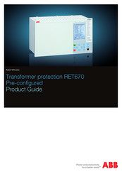
ABB RELION RET670 Product Manual (102 pages)
Brand: ABB
|
Category: Protection Device
|
Size: 2.79 MB
Table of Contents
-
Table of Contents
2
-
Application
3
-
Available Functions
9
-
Functionality
12
-
Hardware Description
27
-
Connection Diagrams
30
-
Technical Data
42
-
Ordering
90

ABB RELION RET670 Communication Protocol Manual (48 pages)
Brand: ABB
|
Category: Power distribution unit
|
Size: 1.4 MB
Table of Contents
-
Table of Contents
7
-
Introduction
9
-
This Manual
9
-
Intended Audience
9
-
Product Documentation
9
-
Product Documentation Set
9
-
Document Revision History
10
-
Related Documents
11
-
Document Symbols and Conventions
12
-
Symbols
12
-
Document Conventions
13
-
SPA Application
15
-
SPA Communication Protocol
15
-
Application
15
-
Setting Guidelines
16
-
SPA Operation Principle
17
-
Operation Principle
17
-
Introduction of SPA Protocol
17
-
SPA Protocol
17
-
I/O Modules
18
-
Single Command, 16 Signals
18
-
Event Function EVENT
20
-
Connection of Signals as Events
21
-
Communication Ports
22
-
Design
22
-
SPA Settings
25
-
Settings
25
-
SPA Technical Data
27
-
Technical Data
27
-
Establishing Connection and Verifying the SPA/IEC Communication
29
-
Entering Settings
29
-
Entering SPA Settings
29
-
Verifying the Communication
29
-
Verifying SPA Communication
29
-
Fiber Optic Loop
30
-
Optical Budget Calculation for Serial Communication with SPA/IEC
30
-
SPA Functions
31
-
SPA, 670 Series Communication Protocol Manual
31
-
Event Function EVENT
31
-
Identification
31
-
Function Block
31
-
Signals
31
-
Settings
32
-
Operation Principle
34
-
Setting Guidelines
35
-
Eventmask (Ch_1 — 16)
35
-
Lonchannelmask or Spachannelmask
35
-
Minrepintval (1 — 16)
36
-
Logical Signal Status Report BINSTATREP
36
-
Identification
36
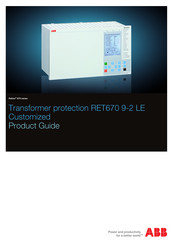
ABB RELION RET670 Product Manual (69 pages)
Relion 670 series
Transformer protection 9-2 LE Customized
Brand: ABB
|
Category: Transformer
|
Size: 2.52 MB
Table of Contents
-
Table of Contents
2
-
Application
3
-
Available Functions
8
-
Differential Protection
8
-
Impedance Protection
8
-
Current Protection
8
-
Voltage Protection
8
-
Secondary System Supervision
9
-
Control
9
-
Logic
9
-
Monitoring
9
-
Metering
10
-
Basic IED Functions
11
-
Human Machine Interface
18
-
Station Communication
18
-
Hardware Description
18
-
Connection Diagrams
21
-
Technical Data
26
-
Ordering
59
Advertisement
Related Products
-
ABB RET650 2.1 IEC
-
ABB RET630
-
ABB RET650 2.2
-
ABB RET615
-
ABB RET 670
-
ABB RET670 ANSI
-
ABB REJ601
-
ABB REM615 ANSI 5.0 FP1
-
ABB REB670 Series
-
ABB REM615 ANSI
ABB Categories
Industrial Equipment
Controller
Battery Charger
Measuring Instruments
DC Drives
More ABB Manuals
Инструкция по оперативному обслуживанию основной защиты T-1 на базе микропроцессорного терминала типа RET-670 на ПС «Гелиос
Знание настоящей инструкции обязательно для:
1. Персонал СРЗА Крымской ЭС;
2. Персонал ЦДС Крымской ЭС;
3. Персонал СРЗА Симферопольских МЭС;
4. Персонал ОДС Симферопольских МЭС;
5. Оперативный персонал группы ПС «Западнокрымская»,»Гелиос»,»Таврия»;
6. ИТР группы ПС «Западнокрымская»,»Гелиос»,»Таврия».
Содержание
1. Введение
2. Технические особенности работы защиты
3. Указание мер безопасности
4. Оперативное обслуживание защиты
Приложение 1 Положение переключающих устройств терминала RET — 670
1. Введение
Терминал RET — 670 является микропроцессорной защитой и предназначен для использования в качестве основной защиты Т-1. Терминал также содержит функции резервных защит Т-1.
Терминал типа RET — 670 включает в себя:
Основная защита:
· дифференциальная защита с:
— внутренней адаптацией к различным коэффициентам трансформации ТТ (нет необходимости использовать промежуточные ТТ);
— торможением при сквозных КЗ;
— блокировкой по форме кривой и по второй гармонике при броске тока намагничивания трансформатора;
— блокировкой по пятой гармонике при перевозбуждении;
— высокой чувствительностью к межвитковым КЗ.
Резервные защиты:
· четырехступенчатая дистанционная защита от всех видов КЗ (не используется):
· четырехступенчатая токовая защита нулевой последовательности (EF4PTOC) (не используется),
· четырехступенчатая МТЗ с токозависимыми / независимыми выдержками времени и органом направления мощности POCM (51/67) для ВН и НН :
· Токовая отсечка IOC;
· функция блокировки от качаний RPSB (78) (не используется);
· контроль исправности цепей напряжения (RFUF) для каждой обмотки Т (не используется);
· защита от тепловой перегрузки PTTR_49;
· защита минимального напряжения PTUV_27 (не используется);
· функция автоматического ускорения резервных защит при включении на повреждение (PSOF) (не используется);
Терминал расположен на панели №4 ПС Гелиос.
Терминал RET — 670 в исправном состоянии должен быть всегда введен в работу.
Основная защита Т-1– RET — 670 находятся в оперативном управлении диспетчера Симферопольских МЭС и ведении диспетчера Крымской ЭС.
2. Технические особенности работы защиты.
2.1.В терминале RET- 670 предусмотрено следующие группы уставок:
Группа уставок №1 – для нормального режима работы Т-1.
2.2.Основная защита Т-1.
2.2.1. В качестве основной защиты Т-1 используется дифференциальная защита с торможением в составе микропроцессорного терминала RET — 670 и с возможностью блокировки по контролю формы тока и наличию гармонических составляющих при бросках намагничивающего тока (БНТ).
Воздействие дифференциальной защиты осуществляется в схемы управления выключателями от внутренних повреждений в Т-1 для отключения со всех сторон.
2.3. Дистанционная защита стороны 110кВ Т-1.
2.3.1. В качестве резервной защит стороны 110 кВ Т-1 используются две ступени дистанционных защит от междуфазных КЗ терминала RET — 670, в качестве которых используются III и IV ступени ДЗ. Указанные ступени по цепям переменного напряжения подключаются через испытательные блоки панели согласно приложения таблицы 1 к ТН — 110 кВ.
2.3.2. По цепям переменного тока указанные ступени подключаются через испытательные блоки панели согласно приложения таблицы 1 на встроенные в Т-1 ТТ 110кВ.
2.3.3. Для повышения надежности резервирования защит от внутренних повреждений в Т, а также резервных защит стороны 110 кВ, IV ступень дистанционных защит направлена в сторону Т-1.
2.3.4. Действие ступеней дистанционных защит стороны 110 кВ Т-1:
— III ступень, направленная в сторону 110 кВ, действует с заданными выдержками времени на отключение выключателя 110 кВ с пуском УРОВ и АПВ.
С третьей выдержкой времени ступень действуют на общевыходную группу реле Т-1.
Данная ступень автоматически ускоряется при опробование Т-1 со стороны 110кВ с воздействием на общевыходную группу реле.
Оперативное ускорение III ступени осуществляется при выводе из работы дифференциальной защиты Т-1 и действует с выдержкой времени на общевыходную группу реле Т-1.
Все ступени блокируются от функционального модуля RFUF при неисправности цепей напряжения.
2.4.Токовые защиты нулевой последовательности стороны 110 кВ Т-1:
2.4.1. В качестве резервных защит от КЗ на землю стороны 110 кВ Т-1 используется
четыре ступени ТЗНП, с выполнением направления трех ступеней в сторону 110 кВ и IV-й ступени в сторону Т-1. Блокирование по 2-й гармонике предусматривается только для оперативно ускоряемой IV ступени при опробование Т-1 со стороны 110кВ.
2.4.2. Действие I, II, III ступеней ТЗНП стороны 110 кВ осуществляется с заданными выдержками времени через общие выходные реле с III зоной дистанционной защиты стороны 110 кВ Т-1.
Действие IV ступени ТЗНП стороны 110 кВ — аналогично действию IV ступени дистанционной защиты стороны 110кВ Т-1.
Автоматическое ускорение аналогично IV зоны ДЗ.
Оперативное ускорение IV ступени ТЗНП выполняемое при выводе из работы диф. защиты Т-1 в RET — 670, действует аналогично оперативному ускорению IV зоны ДЗ стороны 110 кВ Т-1.
2.5.Состав панели:
2.5.1. Панель включает в себя терминал типа RET — 670, резервные защиты, выходные реле, переключатели, указательные реле, испытательные блоки, накладки и сигнальную лампу.
Перечень переключающих устройств и их рабочее положение приведены в приложении таблица 1. Сведения о сигнализации панели приведены в п. 2.10.
Напряжение 220В постоянного тока подается на панель от автомата (SF1) находящегося на панели №…
Терминал RET — 670 может оказаться неготовым к работе или выведенным в следующих случаях:
— при неустойчивых повреждениях внутри терминала или на его выходах, обнаруженных системой самоконтроля;
— при кратковременном исчезновении оперативного постоянного тока на входе панели и его повторном появлении (например, при отыскании «земли» поочередным кратковременным отключением групп присоединений);
2.6. Сигнализация.
2.6.1. При действии устройства или его неисправности срабатывают указательные реле указанные в таблице 1 приложения, своими контактами подающие сигналы для пуска регистратора аварийных событий типа «Рекон».
Срабатывание указательных реле сопровождается загоранием сигнальной лампы ____ на панели RET — 670, работой предупредительной звуковой сигнализации.
2.6.2. На лицевой стороне терминала RET — 670 расположены:
• Светодиоды для индикации состояния устройства:
— 3 светодиода, указывающие состояние терминала (1-зеленый Ready (Готов), 2-желтый Start (Пуск), 3-красный Trip (Отключение))
• Светодиоды аварийной сигнализации, которые состоят из 6 красных и 9 желтых
светодиодов, свободно программируемые пользователем. Могут быть выполнены как с фиксацией так и без.
Расшифровка светодиодной сигнализации приведена в таблицах ниже.
Светодиодная сигнализация состояния терминала для RET670
|
Светодиод, расположенный над дисплеем |
Функция светодиода |
|
Не светится ни один светодиод |
Нет напряжения, или терминал поврежден |
|
Постоянно светится зеленый светодиод |
Терминал готов к работе |
|
Зеленый светодиод мигает |
Внутренняя неисправность, идет запуск |
|
Мигает желтый LED |
Терминал находится в испытательном режиме |
|
Постоянно светится желтый LED |
Запуск отчета об анормальных режимах |
|
Постоянно светится красный LED |
Активизация команды TRIP (отключение). |
|
Мигает красный LED |
Терминал блокирован |
Сброс светодиодной сигнализации терминала осуществляется нажатием кнопки SB1 “Возврат светодиодной сигнализации”
2.7. Взаимодействие с другими устройствами защиты и автоматики.
Выходные реле терминала воздействуют на отключение выключателей и другие устройства РЗА через испытательные блоки в соответствии с таблицей 1 приложения.
Терминал оснащен внутренним регистратором аварийных событий, фиксирующим работу защиты.
3. Указание мер безопасности
3.1. Выполнение работ по техническому обслуживанию ДЗТ на базе REТ — 670 разрешается персоналу служб РЗА или подрядной организации, допущенному к самостоятельной работе на этом устройстве. Работы выполняются по распоряжению при наличии разрешенной оперативной заявки на вывод защиты из работы. При этом у допускаемой бригады оперативными работниками подстанции проверяется наличие исполнительных схем и программы производства работ. Работы необходимо производить в соответствии с требованиями ПБЭЭ (ДНАОП 1.1.10-1.01-97), Правил технического обслуживания устройств РЗА (ГКД 34.35.604-96), Типовой инструкции по организации и производству работ в устройствах РЗА (РД 34.35.302-90).
При работе в цепях ДЗТ Т-1 на базе RET — 670 принять меры, предотвращающие отключение от защиты находящихся в работе присоединений.
Работы на панели защиты должны производиться только инструментом с изоляционным покрытием, соответствующим требованиям Правил эксплуатации электрозащитных средств (ДНАОП 1.1.10-1.07-01).
После окончания работ персонал РЗА должен сделать запись в журнале РЗА ПС «Гелиос» о выполненных работах, отразив при этом характер неисправности (если она была выявлена и устранена), и о возможности ввода в работу ДЗТ Т-1 на базе терминала RET — 670.
3.2. Конструкция панели обеспечивает безопасность обслуживания в соответствии с ГОСТ-12.2.007.7-75.
3.3. Разрешается персоналу СРЗА производить работы в порядке текущей эксплуатации по снятию осциллограмм с помощью ПК, подключенному к терминалу.
4. Оперативное обслуживание защиты
ОПЕРАТИВНОМУ ПЕРСОНАЛУ КАТЕГОРИЧЕСКИ ЗАПРЕЩАЕТСЯ:
манипулировать кнопками управления на лицевой стороне терминала типа RET — 670
4.1. Оперативный ввод и вывод панели из работы.
4.1.1. Подготовка к вводу панели в работу:
1) проверить, что сняты рабочие крышки испытательных блоков цепей выходных воздействий;
2) проверить, что на панели установлены рабочие крышки испытательных блоков цепей переменного тока и напряжения согласно таблицы 1 приложения;
3) включить автоматом оперативный ток панели RET — 670:
— через 10 секунд начнет мигать зеленый светодиод;
— через 10 секунд в окне дисплея появится надпись «Starting» (Пуск терминала);
— через 2 мин на дисплей будет выведено основное меню, в верхней строке будет указано: «Ready» (Готовность).
— в зависимости от свечения зеленого светодиода с левой стороны над дисплеем терминала можно сделать вывод:
а) ровно горящий зеленый светодиод указывает на успешный запуск терминала, что дает право ввода терминала в работу;
б) мигание зеленного светодиода и появление в верхней строке окна, вместо надписи «Ready» (Готов), надписи «Fail» (Неисправность) говорит о внутренней неисправности терминала. Необходимо прекратить ввод терминала RET — 670 в работу, сообщить диспетчеру СМЭС и поставить в известность персонал СРЗА;
— проверить отсутствие свечения светодиодной сигнализации, при необходимости произвести ее сброс, см. п. 2.10.2.;
— проверить отсутствие выпавших блинкеров и сигналов неисправности на панели.
4.1.2. Ввод панели в работу:
— установить переключатель SA1 «Диф. защита» в положение «Введено»;
— установить переключатель SA2 «МТЗ» в положение «Введено»;
— установить переключатель SA3 «ТЗНП» в положение «Введено»;
— установить переключатель SA4 «ДЗ» в положение «Введено»;
— установить переключатель SA5 «Группы уставок» в положение соответствующее режиму работы Т-1;
-проверить отсутствие свечения светодиодной сигнализации, при необходимости произвести ее сброс , см. п. 2.10.2.;
— проверить отсутствие выпавших блинкеров и сигналов неисправности на панели.
— установить рабочие крышки испытательных блоков выходных цепей SG5-SG23 терминала.
4.1.3. Вывод панели из работы:
— установить переключатель SA4 «Диф. защита» в положение «Выведено»;
— установить переключатель SA5 «МТЗ» в положение «Выведено»;
— установить переключатель SA6 «ТЗНП» в положение «Выведено»;
— установить переключатель SA7 «ДЗ» в положение «Выведено»;
— снять рабочие крышки испытательных блоков выходных цепей SG8-SG12 терминала
4.1.4. При оперировании с блоками токовых цепей дифференциальной защиты RET — 670:
вывод любой стороны T-1, необходимо вывести дифференциальную защиту Т-1 RET — 670 из работы с помощью переключателя SA1 «Диф. защита».
4.1.6. При потере цепей напряжения защит по стороне 110 кВ, для предотвращения неправильной работы ступеней дистанционной защиты производится их оперативное блокирование ключом SA4. Этот же ключ используется также для оперативного ввода-вывода дистанционных защит.
4.2. Действия дежурного персонала при срабатывании указательных реле.
4.2.2. При срабатывании указательного реле КН3 «Работа терминала», а также указательных реле таблицы «Положение переключающих устройств и указательных реле Т-1» оперативный персонал подстанции должен:
1) определить по появившейся сигнализации и внешним осмотром что произошло, какие защиты сработали, какие коммутационные аппараты отключались, после чего сделать запись в оперативном журнале и сообщить диспетчеру МЭС;
2) квитировать ключи управления отключившихся коммутационных аппаратов, в том числе отказавшего выключателя;
3) осмотреть все устройства защиты и автоматики Т-1, ВЛ, ДЗШ и переписать все сработавшие указательные реле и светящиеся светодиоды, квитировать их;
4) осмотреть регистраторы аварийных событий и записать в оперативный журнал результаты осмотра;
5) сообщить диспетчеру МЭС об обстановке и о результатах осмотра панелей;
6) дальнейшие действия диспетчера подстанции по ликвидации аварии – по указаниям диспетчера МЭС;
7) после ликвидации аварии записать в журнале учета работы устройств РЗА выпавшие блинкеры и световые сигналы.
Если сигналы не снимаются, сообщить персоналу СРЗА.
4.2.3. Пpи срабатывании указательного реле КН1 «Неисправность устройства RET — 670»:
— вывести терминал из работы, согласно п.4.1.3.;
— записать в оперативном журнале световые сигналы терминала и блинкера на панели;
— доложить диспетчеру МЭС об обстановке, после чего действовать по его указаниям в зависимости от характера сигналов на панели RET- 670;
сообщить персоналу СРЗА.
4.2.4 Пpи срабатывании указательного реле КН2 «Предупредительная сигнализация»:
— в зависимости от свечения зеленого светодиода «Ready» с левой стороны над дисплеем терминала можно сделать вывод:
а) ровно горящий зеленый светодиод указывает на нормальную работоспособность терминала;
б) мигание зеленного светодиода «Ready» говорит о внутренней неисправности терминала. Необходимо вывести терминал из работы, см. п.4.1.3, сообщить диспетчеру МЭС и поставить в известность персонал СРЗА;
-проверить отсутствие свечения светодиодной сигнализации, при необходимости произвести ее сброс нажатием кнопки SB1 «Сброс светодиодов», см. п. 2.10.;
— проверить отсутствие выпавших блинкеров и сигналов неисправности на панели;
— квитировать указательное реле КН2 «Предупредительная сигнализация»:
1) в случае возврата КН2 и отсутствия других неисправностей записать в оперативном журнале световые сигналы терминала и блинкера на панели;
— сообщить персоналу СРЗА.
2) в случае повторного срабатывания КН2 и отсутствия других неисправностей записать в оперативном журнале световые сигналы терминала и блинкера на панели, терминал остается в работе:
— доложить диспетчеру МЭС об обстановке, после чего действовать по его указаниям в зависимости от характера сигналов на панели REТ- 670;
— сообщить персоналу СРЗА.
4.2.5 Пpи срабатывании указательного реле КН7 «Неисправность цепей переменного напряжения»:
— по светодиодной индикации терминала RET — 670 уточнить неисправность TH-110 или(и) TH-10.
— вывести из работы дистанционную защиту соответствующей стороны, с помощью ключей ввода-вывода ДЗ;
— проверить наличие напряжения от ТН на щитовом приборе и включенное положение автоматов цепей переменного напряжения и автомат опер. тока их реле повторителей. Если автоматы цепей переменного напряжения отключены однократно попробовать включить, при повторном отключении принять меры к восстановлению цепей переменного напряжения;
— при устойчивом сигнале на КН7: терминал остается в работе c выведенной функцией ДЗ;
— записать в оперативном журнале световые сигналы на панели;
— доложить диспетчеру МЭС об обстановке, после чего действовать по его указаниям в зависимости от характера сигналов на панели RET — 670.
— сообщить персоналу СРЗА.
4.2.5. Пpи срабатывании указательного реле KH5 «Неисправность цепей оперативного тока»:
— проверить включенное положение автомата оперативного тока терминала RET — 670, в случае отключенного состояния, повторно включить автомат, после чего:
1) если автомат включился, квитировать указательное реле KH5 и сделать запись в оперативном журнале;
2) если автомат не включился или при включенном автомате КН5 не квитируется (есть другие признаки отсутствия оперативного тока), вывести терминал RET — 670 из работы, согласно 4.1.3.:
— записать в оперативном журнале световые сигналы терминала и
блинкера панели RET — 670;
— доложить диспетчеру МЭС об обстановке, после чего действовать по его указаниям в зависимости от характера сигналов на панели RET — 670;
— сообщить персоналу СРЗА.
4.2.6. При срабатывании указательного реле КН4 «Перегруз Т-1» действовать согласно инструкциям по Т-1.
4.2.7. При срабатывании указательного реле КН6 «Работа газовой защиты»
— определить по появившейся сигнализации и внешним осмотром Т-1 что произошло, какие коммутационные аппараты отключались, после чего сделать запись в оперативном журнале и сообщить диспетчеру МЭС;
— квитировать ключи управления отключившихся коммутационных аппаратов, в том числе отказавшего выключателя;
-осмотреть регистраторы аварийных событий и записать в оперативный журнал результаты осмотра;
-сообщить диспетчеру МЭС об обстановке и о результатах осмотра панелей;
-дальнейшие действия диспетчера подстанции по ликвидации аварии – по указаниям диспетчера МЭС;
-после ликвидации аварии записать в журнале учета работы устройств РЗА выпавшие блинкеры и световые сигналы.
ВНИМАНИЕ: во избежание «зависания» терминала ЗАПРЕЩАЕТСЯ отключать автомат опер. тока раньше чем через 3 мин после его включения и включать автомат опер. тока раньше чем через 1 мин после его отключения.
Table of Contents for ABB RELION RET670:
-
Table 51. General current and voltage protection (GAPC), continued Function Range or value Accuracy Undervoltage: Critical impulse time 10 ms typically at 2 to 0 x U set — Impulse margin time 15 ms typically — Secondary system supervision Table 52. Current circuit supervision CCSRDIF Function Range or value Accuracy Operate current (5-200)% of I r ± 10.0% of I r at I £ I r ± 10.0% of I at I > I r Block current (5-500)% of I r ± 5.0% of I r at I £ I r ± 5.0% of I at I > I r Table 53. Fuse
-
Table 78. Line data communication module Characteristic Range or value Type of LDCM Short range (SR) Medium range (MR) Long range (LR) Type of fibre Graded-index multimode 62.5/125 µm or 50/125 µm Singlemode 9/125 µm Singlemode 9/125 µm Wave length 850 nm 1310 nm 1550 nm Optical budget Graded-index multimode 62.5/125 mm, Graded-index multimode 50/125 mm 13 dB (typical distance about 3 km *) 9 dB (typical distance about 2 km *) 22 dB (typical distance 80 km *) 26 dB (typical distance 110 k
-
Contact us ABB AB Substation Automation Products SE-721 59 Västerås, Sweden Phone +46 (0) 21 32 50 00 Fax +46 (0) 21 14 69 18 www.abb.com/substationautomation 1MRK 504 091-BEN B © Copyright 2010 ABB. All rights reserved.
-
by the binary input module and then read by the pulse counter function. A scaled service value is available over the station bus. The special Binary input module with enhanced pulse counting capabilities must be ordered to achieve this functionality. Function for energy calculation and demand handling ETPMMTR Outputs from Measurements (CVMMXU) function can be used to calculate energy. Active as well as reactive values are calculated in import and export direction. Values
-
IED Table 79. Case Material Steel sheet Front plate Steel sheet profile with cut-out for HMI Surface treatment Aluzink preplated steel Finish Light grey (RAL 7035) Table 80. Water and dust protection level according to IEC 60529 Front IP40 (IP54 with sealing strip) Rear, sides, top and bottom IP20 Table 81. Weight Case size Weight 6U, 1/2 x 19” £ 10 kg 6U, 3/4 x 19” £ 15 kg 6U, 1/1 x 19” £ 18 kg Connection system Table 82. CT and VT circuit connectors Connector type Rated voltage and current Maximum conductor area Terminal blocks of feed through
-
Table 12. SOM — Static Output Module (reference standard: IEC 61810-2): Static binary outputs Function of quantity Static binary output trip Rated voltage 48 — 60 VDC 110 — 250 VDC Number of outputs 6 6 Impedance open state ~300 kΩ ~810 kΩ Test voltage across open contact, 1 min No galvanic separation No galvanic separation Current carrying capacity: Continuous 5A 5A 1.0s 10A 10A Making capacity at capacitive load with the maximum capacitance of 0.2 μF : 0.2s 30A 30A 1.0s 10A 10A Breaking capacit
-
Table 10. IOM — Binary input/output module Quantity Rated value Nominal range Binary inputs 8 — DC voltage, RL 24/40 V 48/60 V 110/125 V 220/250 V RL ± 20% RL ± 20% RL ± 20% RL ± 20% Power consumption 24/40 V 48/60 V 110/125 V 220/250 V max. 0.05 W/input max. 0.1 W/input max. 0.2 W/input max. 0.4 W/input — Table 11. IOM — Binary input/output module contact data (reference standard: IEC 61810-2) Function or quantity Trip and signal relays Fast signal relays (parallel reed relay) Binary outputs 10 2 Max system voltage 250 V AC, D
-
User documentation Rule: Specify the number of printed manuals requested Operator’s manual IEC Quantity: 1MRK 504 087-UEN ANSI Quantity: 1MRK 504 087-UUS Technical reference manual IEC Quantity: 1MRK 504 086-UEN ANSI Quantity: 1MRK 504 086-UUS Installation and commissioning manual IEC Quantity: 1MRK 504 088-UEN ANSI Quantity: 1MRK 504 088-UUS Application manual IEC Quantity: 1MRK 504 089-UEN ANSI Quantity: 1MRK 504 089-UUS Engineering guide IED 670 products
-
IN> 4 4 3U> 2 2 3U< 2 2 I->O 51/67 51N/67N 59 27 94/86 87T 3Id/I> IdN/I> 87N IdN/I> 87N 3I> 50BF 3I> 4 4 IN> 4 4 51N/67N SC/VC 25 51/67 3I> 50BF 3I> 4 4 I->O 94/86 TRIP BUSBAR&CB2/3/4 TRIP BUSBAR &CB1/2/4 CB3 TRIP CB3 CB1 TRIP CB1 CB2 S 3I> 50BF TRIP CB1/3/4/X I->O 94/86 TRIP CB2 CB4 3I> 4 4 3I> 50BF TRIP BUSBAR &CB1/2/3 TRIP UN> 2 2 59N t2 I->O 94/86 en05000275.vsd IEC05000275 V1 EN Figure 4. A typical protection application for a three winding t
-
IN> 4 4 3U> 2 2 3U< 2 2 I->O 51/67 51N/67N 59 27 94/86 87T 3Id/I> IdN/I> 87N IdN/I> 87N 3I> 50BF 3I> 4 4 IN> 4 4 51N/67N SC/VC 25 51/67 3I> 50BF 3I> 4 4 I->O 94/86 TRIP BUSBAR&CB2 TRIP BUSBAR &CB1/2 CB3 TRIP CB3 CB1 TRIP CB1 CB2 S 3I> 50BF TRIP CB1/3 I->O 94/86 TRIP CB2 en05000273.vsd IEC05000273 V1 EN Figure 2. A typical protection application for a two winding transformer in multi breaker arrangements is shown on the f
-
Binary inputs and outputs Table 8. BIM — Binary input module Quantity Rated value Nominal range Binary inputs 16 — DC voltage, RL 24/40 V 48/60 V 110/125 V 220/250 V RL ± 20% RL ± 20% RL ± 20% RL ± 20% Power consumption 24/40 V 48/60 V 110/125 V 220/250 V max. 0.05 W/input max. 0.1 W/input max. 0.2 W/input max. 0.4 W/input — Counter input frequency 10 pulses/s max — Oscillating signal discriminator Blocking settable 1�
-
Function description Transformer back-up protection (A10) Voltage control (A25) Single breaker, 2 winding (A30) Multi breaker, 2 winding (B30) Single breaker, 3 winding (A40) Multi breaker, 3 winding (B40) ANSI Basic Option (Qty/ option design) Basic Option (Qty/ option design) Basic Option (Qty/ option design) Basic Option (Qty/ option design) Basic Option (Qty/ option design) Basic Option (Qty/ option design) Apparatus control for up to 6 bays, max 30 apparatuses incl. interlocking (APC30) — — — — — 1/H09 — 1/H09 — 1/H09 — 1/H09 90 Automatic volt
Questions, Opinions and Exploitation Impressions:
You can ask a question, express your opinion or share our experience of ABB RELION RET670 device using right now.
-
7, 87N 50/51P 27P 59P 50/51G 50/51P BKR1 60 49 50BF2 50BF1 50BF4 50BF3 VT’s from MV side of XFRM 94/86 Trip from 50-BF1, 50-BF2 Trip from 50-BF3, 50-BF4 50/51N 50/51N BKR2 BKR4 CT1 CT2 CT7 WDG1 WDG2 59N 50BF5 50/51P 94/86 TRIP BKR5 BKR3 CT3 CT4 WDG3 CT5 67P 24 94/86 TRIP BKR3 TRIP BKR4 94/86 TRIP BKR1 94/86 TRIP BKR2 94/86 94/86 87T ANSI10000089-3-en.vsd ANSI10000089 V3 EN Figure 3. A typ…
-
52, Table 26. Restricted earth fault protection, low impedance REFPDIF (87N) Function Range or value Accuracy Operate characteristic Adaptable ± 1.0% of I n for I < I n ± 1.0% of I for I > I n Reset ratio >95% — Base sensitivity function (4.0-100.0)% of IBase ± 1.0% of I n Directional characteristic Fixed 180 degrees or ± 60 to ± 90 degrees ± 2.0 degre…
-
11, IEC 61850 ANSI Function description Transformer RET670 (A30A) RET670 (B30A) RET670 (B40A) Configuration logic blocks 40-280 40-280 40-280 Fixed signal function blocks 1 1 1 B16I Boolean 16 to Integer conversion 16 16 16 B16IFCVI Boolean 16 to Integer conversion with Logic Node representation 16 16 16 IB16 Integer to Boolean 16…
-
2, Contents 1. Application……………………………………………………………….3 2. Available functions…………………………………………………….8 3. Differential protection……………………………………………….14 4. Current protection……………………………………………………14 5. Voltage protection………………….…
-
39, Figure 18. Typical connection diagram for three winding transformer in a single breaker arrangement. Note! Including IO for control option. Transformer protection RET670 ANSI 1MRK 504 118-BUS A Pre-configured Product version: 1.2 ABB 39
… -
9, Back-up protection functions IEC 61850 ANSI Function description Transformer RET670 (A30A) RET670 (B30A) RET670 (B40A) Current protection OC4PTOC 51_67 Four step phase overcurrent protection 2 2 3 EF4PTOC 51N_67 N Four step residual overcurrent protection 2 2 3 NS4PTOC 46I2 Four step directional negative phase sequence overcurrent protection …
-
64, Secondary system supervision Table 42. Current circuit supervision CCSRDIF (87) Function Range or value Accuracy Operate current (5-200)% of I n ± 10.0% of I n at I £ I n ± 10.0% of I at I > I n Block current (5-500)% of I n ± 5.0% of I n at I £ I n ± 5.0% of I at I > I n Table 43. Fuse failure supervision SDDRFUF Function Range or value Accuracy Operate voltage, zero sequ…
-
40, 189 6289 BUS A TO MAIN 2 TO BB PROT TRM2:7-9 TRM2:1-3 TO BUS PROT TO MAIN 2 RELAY TRM1:11 TRM2:4-6 TRM1:1-3 689 6189 TO MAIN 2 989 TRM1:4-6 = TO SECOND BAY TRM1:12 Res. for Bus 2 VT en05000259_ansi.vsd 87B-TRIP BFI 3PH SUDDEN PRESSURE TRIP MAN SC OK F A U L T S I G N A L L I N G — + IRF WIND TEMP WARN HV 50BF OIL TEMP TRIP WIND TEMP TRIP OIL TEMP WARN OIL LOW GA…
-
16, 5. Voltage protection Two step undervoltage protection UV2PTUV (27) Undervoltages can occur in the power system during faults or abnormal conditions. Two step undervoltage protection (UV2PTUV, 27) function can be used to open circuit breakers to prepare for system restoration at power outages or as long- time delayed back-up to primary protection. UV2PTUV (27) has two voltag…
-
82, Table 83. Inverse time characteristics for residual overvoltage protection Function Range or value Accuracy Type A curve: = — æ ö ç ÷ è ø t td V VPickup VPickup EQUATION1661 V1 EN V = V measured td = (0.05-1.10) in steps of 0.01 Class 5 +40 ms Type B curve: = × — × — — æ ö ç ÷ è ø 2.0 480 32 0.5 0.035 t td V VPickup VPickup EQUATION1662 V1 EN td = (0.…
-
84, Casing #5 Notes and Rules 1/2 x 19″ case A Note: Only for A30A 3/4 x 19″ case 1TRM slot B Note: Only for A30A 1/1 x 19″ case 2 TRM slots E Note: Only for B30A/B40A Selection for position #5. Mounting details with IP40 of protection from the front #6 Notes and Rules No mounting kit included X 19″ rack mounting kit for 1/2 x 19″ c…
-
61, Table 39. Overfrequency protection SAPTOF (81) Function Range or value Accuracy Operate value, pickup function (35.00-75.00) Hz ± 2.0 mHz at symmetrical three- phase voltage Operate time, pickup function 100 ms typically at f set -0.5 Hz to f set +0.5 Hz — Reset time, pickup function 100 ms typically — Operate time, definite time function (0.000-60.000)s ± 0.5% ± 10 ms …
-
83, 20. Ordering Guidelines Carefully read and follow the set of rules to ensure problem-free order management. Please refer to the available functions table for included application functions. PCM600 can be used to make changes and/or additions to the delivered factory configuration of the pre-configured. To obtain the complete ordering code, please combine code from the tables,…
-
62, Multipurpose protection Table 41. General current and voltage protection CVGAPC Function Range or value Accuracy Measuring current input Phase A, Phase B, Phase C, PosSeq, NegSeq, 3*ZeroSeq, MaxPh, MinPh, UnbalancePh, Phase A-Phase B, Phase B-Phase C, Phase C-Phase A, MaxPh- Ph, MinPh-Ph, UnbalancePh-Ph — Base current (1 — 99999) A — Measuring voltage input Phase A, Phase B, Phase C, PosSeq, …
-
73, Remote communication Table 67. Line data communication module Characteristic Range or value Type of LDCM Short range (SR) Medium range (MR) Long range (LR) Type of fiber Graded-index multimode 62.5/125 µm or 50/125 µm Singlemode 9/125 µm Singlemode 9/125 µm Wave length 850 nm 1310 nm 1550 nm Optical budget Graded-index multimode 62.5/125 mm, Graded-index multimode 50/125 mm 13 dB (t…