- Manuals
- Brands
- ABB Manuals
- Surge Protector
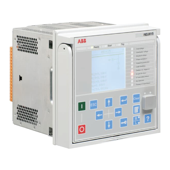
- REU615
- Manual
-
Contents
-
Table of Contents
-
Bookmarks
Quick Links
®
Relion
615 series
Voltage Protection and Control
REU615
DNP3 Point List Manual
Related Manuals for ABB Relion REU 615
Summary of Contents for ABB Relion REU 615
-
Page 1
® Relion 615 series Voltage Protection and Control REU615 DNP3 Point List Manual… -
Page 3
Document ID: 1MRS757056 Issued: 2013-02-21 Revision: C Product version: 4.0 FP1 © Copyright 2013 ABB. All rights reserved… -
Page 4
Copyright This document and parts thereof must not be reproduced or copied without written permission from ABB, and the contents thereof must not be imparted to a third party, nor used for any unauthorized purpose. The software or hardware described in this document is furnished under a license and may be used, copied, or disclosed only in accordance with the terms of such license. -
Page 5
In case any errors are detected, the reader is kindly requested to notify the manufacturer. Other than under explicit contractual commitments, in no event shall ABB be responsible or liable for any loss or damage resulting from the use of this manual or the application of the equipment. -
Page 6
(EMC Directive 2004/108/EC) and concerning electrical equipment for use within specified voltage limits (Low-voltage directive 2006/95/EC). This conformity is the result of tests conducted by ABB in accordance with the product standards EN 50263 and EN 60255-26 for the EMC directive, and with the product standards EN 60255-1 and EN 60255-27 for the low voltage directive. -
Page 7: Table Of Contents
Table of contents Table of contents Section 1 Introduction……………7 This manual………………7 Intended audience…………….7 Product documentation……………7 Product documentation set…………7 Document revision history………….8 Related documentation…………..8 Symbols and conventions…………..9 Symbols………………9 Document conventions…………..9 Functions, codes and symbols…………10 Section 2 DNP3 data mappings………….13 Overview……………….13 Supported functions…………….13 Binary inputs………………15 System functions……………..15 CTRL.LLN0 Local/remote state (also present in DNP IIN-…
-
Page 8
Table of contents LD0.LEDPTRC1 Global protection signals……20 LD0.TRPPTRC1 Global conditioning (1)……..20 LD0.TRPPTRC2 Global conditioning (2)……..21 LD0.FRPFRQ1 Frequency protection (1)…….21 LD0.FRPFRQ2 Frequency protection (2)…….21 LD0.FRPFRQ3 Frequency protection (3)…….21 LD0.FRPFRQ4 Frequency protection (4)…….22 LD0.FRPFRQ5 Frequency protection (5)…….22 LD0.FRPFRQ6 Frequency protection (6)…….22 LD0.LSHDPFRQ1 Load-shedding — instance 1……23 LD0.LSHDPFRQ2 Load-shedding — instance 2……23 LD0.LSHDPFRQ3 Load-shedding — instance 3……23 LD0.LSHDPFRQ4 Load-shedding — instance 4……24… -
Page 9
Table of contents LD0.SECRSYN1 Synchrocheck ……….28 Generic functions……………..29 LD0.MAPGAPC1 Multipurpose analog protection function (1)…………….29 LD0.MAPGAPC2 Multipurpose analog protection function (2)…………….29 LD0.MAPGAPC3 Multipurpose analog protection function (3)…………….29 LD0.MAPGAPC4 Multipurpose analog protection function (4)…………….29 LD0.MAPGAPC5 Multipurpose analog protection function (5)…………….29 LD0.MAPGAPC6 Multipurpose analog protection function (6)…………….30 LD0.MVGAPC1 Multipurpose binary inputs (1)……30 LD0.MVGAPC2 Multipurpose binary inputs (2)……30… -
Page 10
Table of contents Generic functions……………..36 LD0.SPCGGIO1 Multipurpose binary outputs (1)….36 LD0.SPCGGIO2 Multipurpose binary outputs (2)….37 LD0.SRGAPC1 Multipurpose binary outputs — flip-flop resets (1)…………….38 LD0.SRGAPC2 Multipurpose binary outputs — flip-flop resets (2)…………….38 Analog inputs………………38 System functions……………..39 CTRL.LLN0 Local remote station off……..39 LD0.LPHD1 System values…………39 LD0.DNPGGIO1 Active parameter setting group….39 LD0.LEDGGIO1 LHMI LED indications (3 states)….40… -
Page 11
Table of contents Protection functions…………..45 LD0.T2PTTR1 Temperature protection values (2)….45 Protection-related functions…………45 DR.RDRE1 Disturbance recorder values…….45 LD0.SECRSYN1 Synchrocheck line and bus state….45 Generic functions……………..46 LD0.XRGGIO130 RTD inputs……….46 Section 3 DNP3 protocol implementation……..47 DNP3 device profile…………….47 DNP3 implementation table…………..49 Section 4 Glossary……………..53 REU615 Point List Manual… -
Page 13: Section 1 Introduction
Section 1 1MRS757056 C Introduction Section 1 Introduction This manual The point list manual describes the outlook and properties of the data points specific to the IED. The manual should be used in conjunction with the corresponding communication protocol manual. Intended audience This manual addresses the communication system engineer or system integrator responsible for pre-engineering and engineering for communication setup in a…
-
Page 14: Document Revision History
Content updated to correspond to the product version C/2013-02-21 4.0 FP1 Content updated to correspond to the product series version Download the latest documents from the ABB Website http://www.abb.com/substationautomation. 1.3.3 Related documentation Name of the document Document ID DNP3 Communication Protocol Manual…
-
Page 15: Symbols And Conventions
Section 1 1MRS757056 C Introduction Symbols and conventions 1.4.1 Symbols The caution icon indicates important information or warning related to the concept discussed in the text. It might indicate the presence of a hazard which could result in corruption of software or damage to equipment or property.
-
Page 16: Functions, Codes And Symbols
Section 1 1MRS757056 C Introduction 1.4.3 Functions, codes and symbols Table 1: REU615 functions, codes and symbols Function IEC 61850 IEC 60617 IEC-ANSI Protection Three-phase non-directional overcurrent PHLPTOC1 3I> (1) 51P-1 (1) protection, low stage Three-phase non-directional overcurrent PHHPTOC1 3I>> (1) 51P-2 (1) protection, high stage Three-phase non-directional overcurrent…
-
Page 17
Section 1 1MRS757056 C Introduction Function IEC 61850 IEC 60617 IEC-ANSI Multi-purpose protection MAPGAPC1 MAP (1) MAP (1) MAPGAPC2 MAP (2) MAP (2) MAPGAPC3 MAP (3) MAP (3) MAPGAPC4 MAP (4) MAP (4) MAPGAPC5 MAP (5) MAP (5) MAPGAPC6 MAP (6) MAP (6) Load shedding and restoration LSHDPFRQ1… -
Page 19: Section 2 Dnp3 Data Mappings
Section 2 1MRS757056 C DNP3 data mappings Section 2 DNP3 data mappings Overview This document describes the DNP3 data points and structures available in the IED. The data points are unmapped as a default on the DNP3 level. The point lists describe a superset of all DNP3 data available through the standard configuration/s including the optional functionalities.
-
Page 20
Section 2 1MRS757056 C DNP3 data mappings Function block UE01 UE02 PSPTUV2 ● NSPTOV1 ● NSPTOV2 ● FRPFRQ1 ● FRPFRQ2 ● FRPFRQ3 ● FRPFRQ4 ● FRPFRQ5 ● FRPFRQ6 ● T2PTTR1 ● TRPPTRC1 ● ● TRPPTRC2 ● ● ARCSARC1 ARCSARC2 ARCSARC3 MAPGAPC1 MAPGAPC2 MAPGAPC3… -
Page 21: Binary Inputs
Section 2 1MRS757056 C DNP3 data mappings Function block UE01 UE02 TCSSCBR2 ● ● CCRDIF1 ● SEQRFUF1 ● RDRE1 ● ● CMMXU1 ● CSMSQI1 ● VMMXU1 ● ● RESVMMXU1 ● VSMSQI1 ● ● PEMMXU1 ● XRGGIO130 FMMXU1 ● ● = available in the device variant, o = optionally available in the device variant Binary inputs Table 3: Explanations of the binary input table columns…
-
Page 22: Ld0.Lln0 Settings Supervision
Section 2 1MRS757056 C DNP3 data mappings 2.3.1.2 LD0.LLN0 Settings supervision Table 5: LD0.LLN0 Settings supervision IEC 61850 name SA name Description Values LD0.LLN0 .SetChg.stVal Settings changed 1=Changed .SetSeld.stVal Settings reserved 1=Reserved 2.3.2 Switchgear functions 2.3.2.1 CTRL.Cxxxxx1 Circuit breaker (1) CB object and failure protection Table 6: CTRL.Cxxxxx1 Circuit breaker (1) CB object and failure protection IEC 61850 name…
-
Page 23: Ctrl.dxxxxx2 Controllable Disconnector (2)
Section 2 1MRS757056 C DNP3 data mappings 2.3.2.3 CTRL.Dxxxxx2 Controllable disconnector (2) Table 8: CTRL.Dxxxxx2 Controllable disconnector (2) IEC 61850 name SA name Description Values CTRL.DCCILO2 .EnaCls.stVal ENA_CLOSE Close enabled 1=Enabled .EnaOpn.stVal ENA_OPEN Open enabled 1=Enabled .ItlByPss.stVal ITL_BYPASS Interlocking bypass 1=Bypassed CTRL.DCCSWI2 .Pos.stSeld…
-
Page 24: Ld0.Arcsarc2 Fault Arc Protection Stage 2
Section 2 1MRS757056 C DNP3 data mappings 2.3.3.2 LD0.ARCSARC2 Fault arc protection stage 2 Table 11: LD0.ARCSARC2 Fault arc protection stage 2 IEC 61850 name SA name Description Values LD0.ARCSARC21 .FADet.stVal ARC_FLT_DET Arc detected 1=Detected LD0.ARCPTRC21 .Op.general OPERATE Operate 1=Operate 2.3.3.3 LD0.ARCSARC3 Fault arc protection stage 3 Table 12:…
-
Page 25: Automatic Control Functions
Section 2 1MRS757056 C DNP3 data mappings 2.3.4 Automatic control functions 2.3.4.1 LD0.OLATCC1 On-load tap changer controller Table 15: LD0.OLATCC1 On-load tap changer controller IEC 61850 name SA name Description Values LD0.OLATCC1 .ParOp.stVal PARALLEL Parallel or single op. 1=Parallel .Auto.stVal AUTO Auto or manual op.
-
Page 26: Ld0.Vmmxu1 Three-Phase Voltage Limit Supervision
Section 2 1MRS757056 C DNP3 data mappings 2.3.5.3 LD0.VMMXU1 Three-phase voltage limit supervision Table 18: LD0.VMMXU1 Three-phase voltage limit supervision IEC 61850 name SA name Description Values LD0.VMMXU1 .HiAlm.stVal HIGH_ALARM High alarm 1=Alarm .HiWrn.stVal HIGH_WARN High warning 1=Warning .LoAlm.stVal LOW_ALARM Low alarm 1=Alarm .LoWrn.stVal…
-
Page 27: Ld0.Trpptrc2 Global Conditioning (2)
Section 2 1MRS757056 C DNP3 data mappings 2.3.6.3 LD0.TRPPTRC2 Global conditioning (2) Table 22: LD0.TRPPTRC2 Global conditioning (2) IEC 61850 name SA name Description Values .Op.general Operate input signal 1=Operate .Tr.general Trip output signal 1=Trip 2.3.6.4 LD0.FRPFRQ1 Frequency protection (1) Table 23: LD0.FRPFRQ1 Frequency protection (1) IEC 61850 name…
-
Page 28: Ld0.Frpfrq4 Frequency Protection (4)
Section 2 1MRS757056 C DNP3 data mappings IEC 61850 name SA name Description Values .Op.general OPR_OFRQ -Operate 1=Operate LD0.FRPTUF3 Underfrequency .Op.general OPR_UFRQ -Operate 1=Operate LD0.FRPFRC3 Frequency gradient .Op.general OPR_FRG -Operate 1=Operate 2.3.6.7 LD0.FRPFRQ4 Frequency protection (4) Table 26: LD0.FRPFRQ4 Frequency protection (4) IEC 61850 name SA name Description…
-
Page 29: Ld0.Lshdpfrq1 Load-Shedding — Instance 1
Section 2 1MRS757056 C DNP3 data mappings IEC 61850 name SA name Description Values .Op.general OPR_OFRQ -Operate 1=Operate LD0.FRPTUF6 Underfrequency .Op.general OPR_UFRQ -Operate 1=Operate LD0.FRPFRC6 Frequency gradient .Op.general OPR_FRG -Operate 1=Operate 2.3.6.10 LD0.LSHDPFRQ1 Load-shedding — instance 1 Table 29: LD0.LSHDPFRQ1 Load-shedding — instance 1 IEC 61850 name SA name Description…
-
Page 30: Ld0.Lshdpfrq4 Load-Shedding — Instance 4
Section 2 1MRS757056 C DNP3 data mappings 2.3.6.13 LD0.LSHDPFRQ4 Load-shedding — instance 4 Table 32: LD0.LSHDPFRQ4 Load-shedding — instance 4 IEC 61850 name SA name Description Values LD0.LSHDPTRC4 .Op.general OPERATE Stage operate 1=Operate .Str.general START Stage start 1=Start .RestLodOp.general RESTORE Restore the load 1=Restore .RestLodStr.general…
-
Page 31: Ld0.Phhptoc1 Phase Overcurrent Protection — High Stage 1
Section 2 1MRS757056 C DNP3 data mappings 2.3.6.17 LD0.PHHPTOC1 Phase overcurrent protection — high stage 1 Table 36: LD0.PHHPTOC1 Phase overcurrent protection — high stage 1 IEC 61850 name SA name Description Values LD0.PHHPTOC1 .Op.general OPERATE Stage operate 1=Operate .Str.general START Stage start 1=Start…
-
Page 32: Ld0.Phptov3 Phase Overvoltage Protection — Stage 3
Section 2 1MRS757056 C DNP3 data mappings 2.3.6.22 LD0.PHPTOV3 Phase overvoltage protection — stage 3 Table 41: LD0.PHPTOV3 Phase overvoltage protection — stage 3 IEC 61850 name SA name Description Values LD0.PHPTOV3 .Op.general OPERATE Stage operate 1=Operate .Str.general START Stage start 1=Start 2.3.6.23 LD0.PHPTUV1 Phase undervoltage protection — stage 1…
-
Page 33: Ld0.Psptuv2 Positive-Sequence Undervoltage Protection — Stage 2
Section 2 1MRS757056 C DNP3 data mappings 2.3.6.27 LD0.PSPTUV2 Positive-sequence undervoltage protection — stage 2 Table 46: LD0.PSPTUV2 Positive-sequence undervoltage protection — stage 2 IEC 61850 name SA name Description Values LD0.PSPTUV2 .Op.general OPERATE Stage operate 1=Operate .Str.general START Stage start 1=Start 2.3.6.28 LD0.ROVPTOV1 Residual overvoltage protection (1)
-
Page 34: Protection-Related Functions
Section 2 1MRS757056 C DNP3 data mappings 2.3.7 Protection-related functions 2.3.7.1 LD0.CCRDIF1 Current circuit failure protection Table 51: LD0.CCRDIF1 Current circuit failure protection IEC 61850 name SA name Description Values LD0.CCRDIF1 .Alm.stVal FAIL Fail Alarm 1=Alarm .Op.general ALARM Fail Operate 1=Operate 2.3.7.2 LD0.SEQRFUF1 Fuse failure protection…
-
Page 35: Generic Functions
Section 2 1MRS757056 C DNP3 data mappings 2.3.8 Generic functions 2.3.8.1 LD0.MAPGAPC1 Multipurpose analog protection function (1) Table 55: LD0.MAPGAPC1 Multipurpose analog protection function (1) IEC 61850 name SA name Description Values LD0.MAPGAPC1 .Op.general OPERATE Stage operate 1 = Operate .Str.general START Stage start…
-
Page 36: Ld0.Mapgapc6 Multipurpose Analog Protection Function (6)
Section 2 1MRS757056 C DNP3 data mappings 2.3.8.6 LD0.MAPGAPC6 Multipurpose analog protection function (6) Table 60: LD0.MAPGAPC6 Multipurpose analog protection function (6) IEC 61850 name SA name Description Values LD0.MAPGAPC6 .Op.general OPERATE Stage operate 1 = Operate .Str.general START Stage start 1 = Start 2.3.8.7 LD0.MVGAPC1 Multipurpose binary inputs (1)
-
Page 37: Ld0.Spcggio2 Multipurpose Binary Outputs — Status (2)
Section 2 1MRS757056 C DNP3 data mappings 2.3.8.9 LD0.SPCGGIO2 Multipurpose binary outputs — status (2) Table 63: LD0.SPCGGIO2 Multipurpose binary outputs — status (2) IEC 61850 name SA name Description Values LD0.SPCGGIO2 .SPCS01.stVal Output 1 state 0/1=Off/On .SPCS02.stVal Output 2 state 0/1=Off/On .SPCS03.stVal Output 3 state…
-
Page 38: Ld0.Xggio100 Physical I/O
Section 2 1MRS757056 C DNP3 data mappings 2.3.9.3 LD0.XGGIO100 Physical I/O Table 66: LD0.XGGIO100 Physical I/O IEC 61850 name SA name Description Values LD0.XGGIO100 .SPCSO1.stVal X100-Output 1 1/0=ON/OFF .SPCSO2.stVal X100-Output 2 1/0=ON/OFF .SPCSO3.stVal X100-Output 3 1/0=ON/OFF .SPCSO4.stVal X100-Output 4 1/0=ON/OFF .SPCSO5.stVal X100-Output 5 1/0=ON/OFF…
-
Page 39: Binary Outputs
Section 2 1MRS757056 C DNP3 data mappings IEC 61850 name SA name Description Values .Ind6.stVal X130-Input 6 1/0=ON/OFF .SPCSO1.stVal X130-Output 1 1/0=ON/OFF .SPCSO2.stVal X130-Output 2 1/0=ON/OFF .SPCSO3.stVal X130-Output 3 1/0=ON/OFF Binary outputs Table 69: Explanations of the binary output table columns Column name Description IEC 61850…
-
Page 40: Switchgear Functions
Section 2 1MRS757056 C DNP3 data mappings IEC 61850 name SA name Description Type .ActSG4.ctlVal Setting group 4 .ActSG5.ctlVal Setting group 5 .ActSG6.ctlVal Setting group 6 2.4.2 Switchgear functions 2.4.2.1 CTRL.CBCSWI1 Circuit breaker control Table 72: CTRL.CBCSWI1 Circuit breaker control IEC 61850 name SA name Description…
-
Page 41: Metering And Measurand Functions
Section 2 1MRS757056 C DNP3 data mappings 2.4.3 Metering and measurand functions 2.4.3.1 LD0.PEMMXU1 Reset accumulated energy values Table 76: LD0.PEMMXU1 Reset accumulated energy values IEC 61850 name SA name Description Type LD0.PEMMXU1 .SupDmdRs.Oper.ctlVal RSTACM Reset accum. energy 2.4.4 Protection functions 2.4.4.1 LD0.LSHDPFRQ1 Loadshedding controls (1) Table 77:…
-
Page 42: Ld0.Lshdpfrq4 Load Shedding Controls (4)
Section 2 1MRS757056 C DNP3 data mappings 2.4.4.4 LD0.LSHDPFRQ4 Load shedding controls (4) Table 80: LD0.LSHDPFRQ4 Load shedding controls (4) IEC 61850 name SA name Description Type LD0.LSHDPTRC4 .ManRest.Oper.ctlVal MAN_RESTORE Manual restore .BlkRest.Oper.ctlVal BLK_REST Cancel restore 2.4.4.5 LD0.LSHDPFRQ5 Load shedding controls (5) Table 81: LD0.LSHDPFRQ5 Load shedding controls (5) IEC 61850 name…
-
Page 43: Ld0.Spcggio2 Multipurpose Binary Outputs (2)
Section 2 1MRS757056 C DNP3 data mappings IEC 61850 name SA name Description Type .SPCS04.ctlVal Output 4 control On/Off .SPCS05.ctlVal Output 5 control On/Off .SPCS06.ctlVal Output 6 control On/Off .SPCS07.ctlVal Output 7 control On/Off .SPCS08.ctlVal Output 8 control On/Off .SPCS09.ctlVal Output 9 control On/Off .SPCS10.ctlVal…
-
Page 44: Ld0.Srgapc1 Multipurpose Binary Outputs — Flip-Flop Resets (1)
Section 2 1MRS757056 C DNP3 data mappings 2.4.6.3 LD0.SRGAPC1 Multipurpose binary outputs — flip-flop resets (1) Table 85: LD0.SRGAPC1 Multipurpose binary outputs — flip-flop resets (1) IEC 61850 name SA name Description Type LD0.SRGAPC1 .Rs1.ctlVal Reset flip-flop 1 .Rs2.ctlVal Reset flip-flop 2 .Rs3.ctlVal Reset flip-flop 3 .Rs4.ctlVal…
-
Page 45: System Functions
Section 2 1MRS757056 C DNP3 data mappings Column name Description Values The value range of the original IEC 61850 data. Scaling is needed to convert floating point data into DNP3 integer values. Scaling type selected as default. Default “R” means ratio scaling. See the DNP communication protocol manual for details.
-
Page 46: Ld0.Ledggio1 Lhmi Led Indications (3 States)
Section 2 1MRS757056 C DNP3 data mappings 2.5.1.4 LD0.LEDGGIO1 LHMI LED indications (3 states) Table 91: LD0.LEDGGIO1 LHMI LED indications (3 states) IEC 61850 name SA name Description Values Arg 1,2,3,4 LD0.LEDGGIO1 0/1/3=Off/Ok/ .ISCSO1.stVal LED 1 state Alarm 0,3,0,3 0/1/3=Off/Ok/ .ISCSO2.stVal LED 2 state Alarm…
-
Page 47: Ctrl.dcsxswi2 Disconnector 2, 4-Pole (2 Bit) Position Values
Section 2 1MRS757056 C DNP3 data mappings 2.5.2.3 CTRL.DCSXSWI2 Disconnector 2, 4-pole (2 bit) position values Table 94: CTRL.DCSXSWI2 Disconnector 2, 4-pole (2 bit) position values IEC 61850 name SA name Description Values Arg 1,2,3,4 CTRL.DCSXSWI2 Intermediate=0; Off=1; On=2; .Pos.stVal POSITION Bad=3 0…3…
-
Page 48: Ctrl.essxswi2 Earth Switch 2, 4-Pole (2 Bit) Position Values
Section 2 1MRS757056 C DNP3 data mappings 2.5.2.8 CTRL.ESSXSWI2 Earth switch 2, 4-pole (2 bit) position values Table 99: CTRL.ESSXSWI2 Earth switch 2, 4-pole (2 bit) position values IEC 61850 name SA name Description Values Arg 1,2,3,4 CTRL.ESSXSWI2 Intermediate=0; Off=1; On=2; .Pos.stVal POSITION Bad=3…
-
Page 49: Metering And Measurand Functions
Section 2 1MRS757056 C DNP3 data mappings 2.5.5 Metering and measurand functions 2.5.5.1 LD0.CMMXU1 Phase currents (1) Table 103: LD0.CMMXU1 Phase currents (1) IEC 61850 name SA name Description Values Arg 1,2,3,4 LD0.CMMXU1 Phase-to-ground current .A.phsA.instCVal.mag I_INST_A -phsA magnitude 0.00..40.0 [xIn] 0,40,0,4000 .A.phsB.instCVal.mag I_INST_B…
-
Page 50: Ld0.Resvmmxu1 Residual Voltage (1)
Section 2 1MRS757056 C DNP3 data mappings IEC 61850 name SA name Description Values Arg 1,2,3,4 0.00…4.00 .phsAB.cVal.mag U_DB_AB -phsAB magnitude [xUn] 0,4,0,400 0.00…4.00 .phsBC.cVal.mag U_DB_BC -phsBC magnitude [xUn] 0,4,0,400 0.00…4.00 .phsCA.cVal.mag U_DB_CA -phsCA magnitude [xUn] 0,4,0,400 2.5.5.5 LD0.RESVMMXU1 Residual voltage (1) Table 107: LD0.RESVMMXU1 Residual voltage (1) IEC 61850 name…
-
Page 51: Ld0.Fmmxu1 Frequency Measurement
Section 2 1MRS757056 C DNP3 data mappings 2.5.5.8 LD0.FMMXU1 Frequency measurement Table 110: LD0.FMMXU1 Frequency measurement IEC 61850 name SA name Description Values Arg 1,2,3,4 LD0.FMMXU1 .Hz.mag Frequency value 35…75 [Hz] 35,75,3500,7500 2.5.6 Protection functions 2.5.6.1 LD0.T2PTTR1 Temperature protection values (2) Table 111: LD0.T2PTTR1 Temperature protection values (2) IEC 61850 name…
-
Page 52: Generic Functions
Section 2 1MRS757056 C DNP3 data mappings 2.5.8 Generic functions 2.5.8.1 LD0.XRGGIO130 RTD inputs Table 114: LD0.XRGGIO130 RTD inputs IEC 61850 name SA name Description Values Arg 1,2,3,4 -10000… .AnIn1.instMag AI_VAL1 RTD input 1 10000 -1E4,1E4,-1E4,1E4 -10000… .AnIn2.instMag AI_VAL2 RTD input 2 10000 -1E4,1E4,-1E4,1E4 -10000……
-
Page 53: Section 3 Dnp3 Protocol Implementation
Implementation table and the point list tables, provides a complete configuration/interoperability guide for communicating with a device. Table 115: Device profile document DNP3 device profile document Vendor name: ABB Oy Device name: REU615 Highest DNP level supported: Device function: For requests: Level 2+ ○…
-
Page 54
Section 3 1MRS757056 C DNP3 protocol implementation DNP3 device profile document ○ Sometimes ● Configurable as: «Only when reporting event data», or «When reporting event data or multi-fragment messages» Timeouts while waiting for: Data link ○ None ○ Fixed at ____ ○… -
Page 55: Dnp3 Implementation Table
Section 3 1MRS757056 C DNP3 protocol implementation DNP3 device profile document ○ Configurable ○ When device restarts ○ Only certain objects ○ When status flags change ○ Sometimes (attach explanation) ○ ENABLE/DISABLE UNSOLICITED No other options are permitted. function codes supported Default counter object/variation: Counters roll over at: ●…
-
Page 56
Section 3 1MRS757056 C DNP3 protocol implementation Table 116: Implementation table OBJECT REQUEST (Library will parse) RESPONSE (Library will respond with) Object Variation Function codes Qualifier codes number number Description Function codes (dec) Qualifier codes (hex) (dec) (hex) Binary 1 (read) 00, 01 (start-stop) input –… -
Page 57
Section 3 1MRS757056 C DNP3 protocol implementation OBJECT REQUEST (Library will parse) RESPONSE (Library will respond with) 16-bit 1 (read) 00, 01 (start-stop) 129 (response) 00, 01 (start-stop) 2 (default) analog 06 (no range, or all) 17, 28 (index) input 07, 08 (limited qty) 17, 28 (index) 32-bit… -
Page 58
Section 3 1MRS757056 C DNP3 protocol implementation OBJECT REQUEST (Library will parse) RESPONSE (Library will respond with) Time delay 129 (response) 07 (limited qty) fine (qty = 1) Not defined Class 0 1 (read) 06 (no range, or all) data Class 1 1 (read) 06 (no range, or all) -
Page 59: Section 4 Glossary
Section 4 1MRS757056 C Glossary Section 4 Glossary Application function block library CROB Control relay output block Common time of occurrence. The time and date CTO object is an information object that represents the absolute time of day. DNP3 A distributed network protocol originally developed by Westronic.
-
Page 64
Contact us ABB Oy Medium Voltage Products, Distribution Automation P.O. Box 699 FI-65101 VAASA, Finland Phone +358 10 22 11 +358 10 22 41094 ABB Limited Distribution Automation Maneja Vadodara 390013, India Phone +91 265 2604032 +91 265 2638922 www.abb.com/substationautomation…
-
Contents
-
Table of Contents
-
Bookmarks
Quick Links
®
Relion
615 series
Voltage Protection and Control
REU615
Product Guide
Related Manuals for ABB REU615
Summary of Contents for ABB REU615
-
Page 1
® Relion 615 series Voltage Protection and Control REU615 Product Guide… -
Page 2: Table Of Contents
15. Current circuit supervision………..14 Disclaimer The information in this document is subject to change without notice and should not be construed as a commitment by ABB. ABB assumes no responsibility for any errors that may appear in this document. © Copyright 2012 ABB.
-
Page 3: Description
CB control, measuring and supervising can be altered by means of the graphical signal ® functions. REU615 is a member of ABB’s Relion matrix or the graphical application functionality of product family and part of its 615 protection and the Protection and Control IED Manager PCM600.
-
Page 4
Voltage Protection and Control 1MRS757058 D REU615 Product version: 4.0 Table 2. Supported functions Functionality Protection Three-phase non-directional overcurrent protection, low stage, instance 1 ● Three-phase non-directional overcurrent protection, high stage, instance 1 ● Three-phase non-directional overcurrent protection, instantaneous stage, instance 1 ●… -
Page 5
Voltage Protection and Control 1MRS757058 D REU615 Product version: 4.0 Table 2. Supported functions, continued Functionality Multi-purpose protection, instance 6 Load shedding and restoration, instance 1 ● Load shedding and restoration, instance 2 ● Load shedding and restoration, instance 3 ●… -
Page 6: Protection Functions
Voltage Protection and Control 1MRS757058 D REU615 Product version: 4.0 Table 2. Supported functions, continued Functionality RTD/mA measurement Frequency measurement ● ● = included, o = optional at the time of order The instances of a protection function represent the number of identical function blocks available in a standard configuration. By setting the application specific parameters of an instance, a protection function stage can be established.
-
Page 7
Voltage Protection and Control 1MRS757058 D REU615 Product version: 4.0 and the timers of the protection function can be set to operate when the input values are below or exceeds the set values. GUID-5E258DF3-B410-4FEE-9925-A8FC9C3617CE V2 EN Figure 1. Protection function overview of standard configuration A… -
Page 8: Application
Standard configuration A REU615 can be used for loss-of-mains (LOM) protection for single power generating units. The A configuration of REU615 is intended to be used in medium voltage switchgear, supplied with Standard configuration B a dedicated voltage measurement cubicle. The A…
-
Page 9
REU615 and REF615 are employed for busbar protection for the voltage measurement bay and related parts of the busbar. Apart from the busbar protection and supervision the REU615 IED is utilized for centralized load shedding (disconnection) and restoration (reconnection) of one of the outgoing feeders. -
Page 10: Supported Abb Solutions
GUID-A90B4035-68B9-4264-83C5-DD791DDEDAB0 V2 EN Figure 4. Tap changer control and power transformer thermal overload protection using REU615 with the standard configuration B. The tap changer position information is received as a mA-signal from the tap changer operation mechanism. The position value is sent to the transformer differential protection function of the RET615 IED using GOOSE messaging.
-
Page 11
MicroSCADA Pro features of COM600. The data historian can be and System 800xA used for accurate process performance monitoring by following process and equipment Table 3. Supported ABB solutions Product Version Grid Automation controller COM600 3.5 or later MicroSCADA Pro SYS 600 9.3 FP1 or later… -
Page 12: Control
Voltage Protection and Control 1MRS757058 D REU615 Product version: 4.0 GUID-6984D893-45D5-427A-BABF-F1E1015C18E2 V3 EN Figure 6. Industrial power system example using 615 series IEDs, Grid Automation controller COM600 and System 800xA 6. Control voltage and voltage phase sequence component The IED offers control of one circuit breaker with measurement.
-
Page 13: Disturbance Recorder
Voltage Protection and Control 1MRS757058 D REU615 Product version: 4.0 remotely using the web-browser based user record includes current, voltage and angle values, interface. time stamp, etc. The fault recording can be triggered by the start signal or the trip signal of a protection block, or by both.
-
Page 14: Current Circuit Supervision
Voltage Protection and Control 1MRS757058 D REU615 Product version: 4.0 15. Current circuit supervision The residual current input and the phase-current Current circuit supervision is used for detecting inputs are rated 1/5 A. The three phase-voltage faults in the current transformer secondary inputs and the residual-voltage input covers the circuits.
-
Page 15: Station Communication
IED simultaneously. values, such as surrounding temperature values, Further, Modbus serial and Modbus TCP can be to other IED applications. In REU615 analog used in parallel, and if required both IEC 61850 GOOSE messaging is employed in control and Modbus protocols can be run simultaneously.
-
Page 16
Voltage Protection and Control 1MRS757058 D REU615 Product version: 4.0 connections are supported. Termination and pull- With special time synchronization wiring: up/down resistors can be configured with jumpers • IRIG-B (Inter-Range Instrumentation Group — on the communication card so external resistors Time Code Format B) are not needed. -
Page 17
Voltage Protection and Control 1MRS757058 D REU615 Product version: 4.0 Table 5. Supported station communication interfaces and protocols Interfaces/Protocols Ethernet Serial 100BASE-TX RJ-45 100BASE-FX LC RS-232/RS-485 Fibre-optic ST IEC 61850 ● ● MODBUS RTU/ASCII ● ● MODBUS TCP/IP ● ●… -
Page 18: Technical Data
Voltage Protection and Control 1MRS757058 D REU615 Product version: 4.0 19. Technical data Table 6. Dimensions Description Value Width frame 177 mm case 164 mm Height frame 177 mm (4U) case 160 mm Depth 201 mm (153 + 48 mm)
-
Page 19
Voltage Protection and Control 1MRS757058 D REU615 Product version: 4.0 Table 8. Energizing inputs Description Value Rated frequency 50/60 Hz ± 5 Hz Current inputs Rated current, I 1/5 A Thermal withstand capability: • Continuously 20 A • For 1 s… -
Page 20
Voltage Protection and Control 1MRS757058 D REU615 Product version: 4.0 Table 10. RTD/mA measurement (XRGGIO130) Description Value RTD inputs Supported RTD 100 Ω platinum TCR 0.00385 (DIN 43760) sensors 250 Ω platinum TCR 0.00385 100 Ω nickel TCR 0.00618 (DIN 43760) 120 Ω… -
Page 21
Voltage Protection and Control 1MRS757058 D REU615 Product version: 4.0 Table 12. Signal outputs and IRF output Description Value Rated voltage 250 V AC/DC Continuous contact carry Make and carry for 3.0 s 10 A Make and carry 0.5 s… -
Page 22
Voltage Protection and Control 1MRS757058 D REU615 Product version: 4.0 Table 16. Station communication link, fibre-optic Connector Wave length Max. distance Fibre type Permitted path attenuation MM 62.5/125 or 50/125 1300 nm 2 km <8 dB μm glass fibre core MM 62.5/125 or 50/125… -
Page 23
Voltage Protection and Control 1MRS757058 D REU615 Product version: 4.0 Table 21. Environmental tests Description Type test value Reference Dry heat test • 96 h at +55ºC IEC 60068-2-2 • 16 h at +85ºC Dry cold test • 96 h at -25ºC IEC 60068-2-1 •… -
Page 24
Voltage Protection and Control 1MRS757058 D REU615 Product version: 4.0 Table 22. Electromagnetic compatibility tests Description Type test value Reference 1 MHz/100 kHz burst disturbance IEC 61000-4-18 test: IEC 60255-22-1, class III IEEE C37.90.1-2002 • Common mode 2.5 kV • Differential mode 2.5 kV… -
Page 25
Voltage Protection and Control 1MRS757058 D REU615 Product version: 4.0 Table 22. Electromagnetic compatibility tests, continued Description Type test value Reference Voltage dips and short interruptions: 30%/10 ms IEC 61000-4-11 60%/100 ms 60%/1000 ms >95%/5000 ms Power frequency immunity test:… -
Page 26
Voltage Protection and Control 1MRS757058 D REU615 Product version: 4.0 Table 25. Product safety Description Reference LV directive 2006/95/EC Standard EN 60255-27 (2005) EN 60255-1 (2009) Table 26. EMC compliance Description Reference EMC directive 2004/108/EC Standard EN 50263 (2000) EN 60255-26 (2007) Table 27. -
Page 27
Voltage Protection and Control 1MRS757058 D REU615 Product version: 4.0 Protection functions Table 28. Three-phase non-directional overcurrent protection (PHxPTOC) Characteristic Value Operation accuracy Depending on the frequency of the current measured: f ±2 Hz PHLPTOC ±1.5% of the set value or ±0.002 x I PHHPTOC ±1.5% of set value or ±0.002 x I… -
Page 28
Voltage Protection and Control 1MRS757058 D REU615 Product version: 4.0 Table 29. Three-phase non-directional overcurrent protection (PHxPTOC) main settings Parameter Function Value (Range) Step Start Value PHLPTOC 0.05…5.00 x I 0.01 PHHPTOC 0.10…40.00 x I 0.01 PHIPTOC 1.00…40.00 x I 0.01… -
Page 29
Voltage Protection and Control 1MRS757058 D REU615 Product version: 4.0 Table 31. Three-phase overvoltage protection (PHPTOV) main settings Parameter Function Value (Range) Step Start value PHPTOV 0.05…1.60 x U 0.01 Time multiplier PHPTOV 0.05…15.00 0.01 Operate delay time PHPTOV 40…300000 ms… -
Page 30
Voltage Protection and Control 1MRS757058 D REU615 Product version: 4.0 Table 34. Positive-sequence undervoltage protection (PSPTUV) Characteristic Value Operation accuracy Depending on the frequency of the voltage measured: f ±2 Hz ±1.5% of the set value or ±0.002 x U… -
Page 31
Voltage Protection and Control 1MRS757058 D REU615 Product version: 4.0 Table 37. Negative-sequence overvoltage protection (NSPTOV) main settings Parameter Function Value (Range) Step Start value NSPTOV 0.010…1.000 x U 0.001 Operate delay time NSPTOV 40…120000 ms Table 38. Frequency protection (FRPFRQ) -
Page 32
Voltage Protection and Control 1MRS757058 D REU615 Product version: 4.0 Table 40. Thermal overload protection, two time constants (T2PTTR) Characteristic Value Operation accuracy Depending on the frequency of the current measured: f ±2 Hz Current measurement: ±1.5% of the set value or ±0.002 (at currents in the range of 0.01…4.00 x I… -
Page 33
Voltage Protection and Control 1MRS757058 D REU615 Product version: 4.0 Table 43. Residual overvoltage protection (ROVPTOV) main settings Parameter Function Value (Range) Step Start value ROVPTOV 0.010…1.000 x U 0.001 Operate delay time ROVPTOV 40…300000 ms Table 44. Arc protection (ARCSARC) -
Page 34
Voltage Protection and Control 1MRS757058 D REU615 Product version: 4.0 Table 48. Load shedding (LSHDPFRQ) Characteristic Value Operation accuracy f< ±10 mHz df/dt ±100 mHz/s (in range |df/dt| < 5 Hz/s) ± 2.0% of the set value (in range 5 Hz/ s <… -
Page 35
Voltage Protection and Control 1MRS757058 D REU615 Product version: 4.0 Table 50. Operation characteristics Parameter Values (Range) Operating curve type 1=ANSI Ext. inv. 2=ANSI Very. inv. 3=ANSI Norm. inv. 4=ANSI Mod inv. 5=ANSI Def. Time 6=L.T.E. inv. 7=L.T.V. inv. 8=L.T. inv. -
Page 36
Voltage Protection and Control 1MRS757058 D REU615 Product version: 4.0 Control functions Table 51. Synchrocheck (SECRSYN) Characteristic Value Operation accuracy Depending on the frequency of the voltage measured: f ±1 Hz Voltage: ±3.0% of the set value or ±0.01 x U Frequency: ±10 mHz… -
Page 37
Voltage Protection and Control 1MRS757058 D REU615 Product version: 4.0 Table 52. Synchronism and energizing check (SECRSYN) main settings Parameter Values (Range) Unit Step Default Description Live dead mode -1=Off 1=Both Dead Energizing check 1=Both Dead mode 2=Live L, Dead B… -
Page 38
Voltage Protection and Control 1MRS757058 D REU615 Product version: 4.0 Table 52. Synchronism and energizing check (SECRSYN) main settings, continued Parameter Values (Range) Unit Step Default Description Maximum Syn 100…6000000 2000 Maximum time to time accept synchronizing Energizing time 100…60000… -
Page 39
Voltage Protection and Control 1MRS757058 D REU615 Product version: 4.0 Table 54. On-load tap changer control with voltage regulator (OLATCC) main settings Parameter Function Value (Range) Step Band center voltage OLATCC 0.000…2.000 x Un 0.001 Control delay time 1 OLATCC 1000…300000 ms… -
Page 40
Voltage Protection and Control 1MRS757058 D REU615 Product version: 4.0 Measurement functions Table 55. Three-phase current measurement (CMMXU) Characteristic Value Operation accuracy Depending on the frequency of the current measured: f ±2 Hz ±0.5% or ±0.002 x I (at currents in the range of 0.01…4.00 x I… -
Page 41
Voltage Protection and Control 1MRS757058 D REU615 Product version: 4.0 Table 59. Three-phase power and energy (PEMMXU) Characteristic Value Operation accuracy At all three currents in range 0.10…1.20 x I At all three voltages in range 0.50…1.15 x U At the frequency f ±1 Hz… -
Page 42
Voltage Protection and Control 1MRS757058 D REU615 Product version: 4.0 Supervision functions Table 62. Current circuit supervision (CCRDIF) Characteristic Value < 30 ms Operate time Including the delay of the output contact. Table 63. Current circuit supervision (CCRDIF) main settings… -
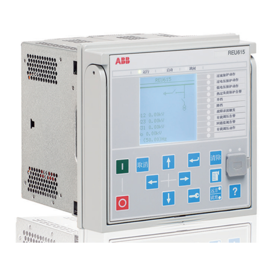
Page 43: Local Hmi
Voltage Protection and Control 1MRS757058 D REU615 Product version: 4.0 20. Local HMI default single line diagram. The SLD view can also The IED is available with two optional displays, a be accessed using the web-browser based user large one and a small one. The large display is interface.
-
Page 44: Mounting Methods
Voltage Protection and Control 1MRS757058 D REU615 Product version: 4.0 Table 66. Large display Rows in the view Characters per row Character size Small, mono-spaced (6×12 pixels) Large, variable width (13×14 pixels) 8 or more Depending on the selected language 21.
-
Page 45: Ied Case And Ied Plug-In Unit
Voltage Protection and Control 1MRS757058 D REU615 Product version: 4.0 22. IED case and IED plug-in unit on the upper part of the plug-in-unit. An order For safety reasons, the IED cases for current number label is placed on the side of the plug-in measuring IEDs are provided with automatically unit as well as inside the case.
-
Page 46
Voltage Protection and Control 1MRS757058 D REU615 Product version: 4.0 The communication module hardware determines the available communication proto — H B U B C C A H C 1 B B N 1 X E cols. Choose the hardware from one of the rows below to define the digits # 9-10. -
Page 47
Voltage Protection and Control 1MRS757058 D REU615 Product version: 4.0 H B U B C C A H B C C 1 B B N 1 Description Language English English and German English and Swedish English and Spanish English and Russian… -
Page 48: Accessories And Ordering Data
Voltage Protection and Control 1MRS757058 D REU615 Product version: 4.0 24. Accessories and ordering data Table 67. Cables Item Order number Cable for optical sensors for arc protection 1.5 m 1MRS120534-1.5 Cable for optical sensors for arc protection 3.0 m 1MRS120534-3.0…
-
Page 49: Tools
IED can be accessed either locally or Table 69. Tools Configuration and setting tools Version PCM600 2.4 SP1 or later Web-browser based user interface IE 7.0, IE 8.0 or IE 9.0 REU615 Connectivity Package 4.0 or later…
-
Page 50
Voltage Protection and Control 1MRS757058 D REU615 Product version: 4.0 Table 70. Supported functions Function WebHMI PCM600 Basic/ PCM600 Engineering Engineering IED parameter setting ● ● ● Saving of IED parameter settings in the IED ● ● ● Signal monitoring ●… -
Page 51: Terminal Diagrams
Voltage Protection and Control 1MRS757058 D REU615 Product version: 4.0 26. Terminal diagrams GUID-B89BFFF3-08F0-40D3-8F12-99FB21B3900F V1 EN Figure 14. Terminal diagram of standard configuration A…
-
Page 52
Voltage Protection and Control 1MRS757058 D REU615 Product version: 4.0 GUID-E5FA44B9-524F-4B19-A002-49D39DF6D6D5 V1 EN Figure 15. Terminal diagram of standard configuration B… -
Page 53: References
You will find the latest relevant information on the The Features and Application tabs contain REU615 protection IED on the product page. product related information in a compact format. GUID-2ECAAEFE-CEF1-4A31-97F4-B88FCF66DB8E V1 EN Figure 16.
-
Page 54: Functions, Codes And Symbols
Voltage Protection and Control 1MRS757058 D REU615 Product version: 4.0 28. Functions, codes and symbols Table 71. REU615 functions, codes and symbols Function IEC 61850 IEC 60617 IEC-ANSI Protection Three-phase non-directional overcurrent protection, low PHLPTOC1 3I> (1) 51P-1 (1) stage…
-
Page 55
Voltage Protection and Control 1MRS757058 D REU615 Product version: 4.0 Table 71. REU615 functions, codes and symbols, continued Function IEC 61850 IEC 60617 IEC-ANSI Multi-purpose protection MAPGAPC1 MAP (1) MAP (1) MAPGAPC2 MAP (2) MAP (2) MAPGAPC3 MAP (3) MAP (3) -
Page 56: Document Revision History
Voltage Protection and Control 1MRS757058 D REU615 Product version: 4.0 Table 71. REU615 functions, codes and symbols, continued Function IEC 61850 IEC 60617 IEC-ANSI Residual voltage measurement RESVMMXU1 Sequence voltage measurement VSMSQI1 U1, U2, U0 U1, U2, U0 Three-phase power and energy measurement…
-
Page 60
Contact us ABB Oy Distribution Automation P.O. Box 699 FI-65101 VAASA, Finland Phone +358 10 22 11 +358 10 22 41094 www.abb.com/substationautomation…
Specifications:
|
Accompanying Data:
ABB REU615 Controller, Control Unit PDF Product Manual (Updated: Thursday 6th of April 2023 11:35:28 PM)
Rating: 4.6 (rated by 16 users)
Compatible devices: Shunt Trip AA, Circuit Shield 87B, TPME Series, KH-2, i-bus FCC/S 1 1 Series, RED670 Relion 670 series, SafeGear, Relion REM615.
Recommended Documentation:
ABB REU615: Text of Product Manual
(Ocr-Read Version Summary of Contents, UPD: 06 April 2023)
-
18, 19. Technical data Table 6. Dimensions Description Value Width frame 177 mm case 164 mm Height frame 177 mm (4U) case 160 mm Depth 201 mm (153 + 48 mm) Weight complete IED 4.1 kg plug-in unit only 2.1 kg Table 7. Power supply Description Type 1 Type 2 U aux nominal 100, 110, 120, 220, 240 V AC, 50 and 60 Hz 24, 30, 48, 60 V DC 48, 60, 110, 125, 220, 250 V DC Max…
-
9, GUID-CA7B4D3E-1269-450F-A061-5A404FF52455 V2 EN Figure 3. Busbar protection and supervision using REU615 with the standard configuration A. The arc protection schemes of REU615 and REF615 are employed for busbar protection for the voltage measurement bay and related parts of the busbar. Apart from the busbar protection and supervision the REU615 IED is utilized for centralized lo…
-
45, 22. IED case and IED plug-in unit For safety reasons, the IED cases for current measuring IEDs are provided with automatically operating contacts for short-circuiting the CT secondary circuits when a IED unit is withdrawn from its case. The IED case is further provided with a mechanical coding system preventing current measuring IED units from being inserted into a IED case for a…
-
28, Table 29. Three-phase non-directional overcurrent protection (PHxPTOC) main settings Parameter Function Value (Range) Step Start Value PHLPTOC 0.05…5.00 x I n 0.01 PHHPTOC 0.10…40.00 x I n 0.01 PHIPTOC 1.00…40.00 x I n 0.01 Time multiplier PHLPTOC 0.05…15.00 0.01 PHHPTOC 0.05…15.00 0.01 Operate delay time PHLPTOC 40…200000 ms 10 PHHPTOC 40…200000 ms 10 PHIPTOC 20…200000 …
-
52, GUID-E5FA44B9-524F-4B19-A002-49D39DF6D6D5 V1 EN Figure 15. Terminal diagram of standard configuration B Voltage Protection and Control 1MRS757058 D REU615 Product version: 4.0 52 ABB
… -
31, Table 37. Negative-sequence overvoltage protection (NSPTOV) main settings Parameter Function Value (Range) Step Start value NSPTOV 0.010…1.000 x U n 0.001 Operate delay time NSPTOV 40…120000 ms 1 Table 38. Frequency protection (FRPFRQ) Characteristic Value Operation accuracy f>/f< ±10 mHz df/dt ±100 mHz/s (in range |df/dt| < 5 Hz/s) ± 2.0% of the set …
-
12, GUID-6984D893-45D5-427A-BABF-F1E1015C18E2 V3 EN Figure 6. Industrial power system example using 615 series IEDs, Grid Automation controller COM600 and System 800xA 6. Control The IED offers control of one circuit breaker with dedicated push-buttons for circuit breaker opening and closing. Further, the optional large graphical LCD of the IED’s HMI includes a single- lin…
-
22, Table 16. Station communication link, fibre-optic Connector Fibre type 1) Wave length Max. distance Permitted path attenuation 2) LC MM 62.5/125 or 50/125 μm glass fibre core 1300 nm 2 km <8 dB ST MM 62.5/125 or 50/125 μm glass fibre core 820-900 nm 1 km <11 dB 1) (MM) multi-mode fibre, (SM) single-mode fibre 2) Maximum allowed attenuation caused by connectors and ca…
-
5, Table 2. Supported functions, continued Functionality A B Multi-purpose protection, instance 6 4) — o 5) Load shedding and restoration, instance 1 ● — Load shedding and restoration, instance 2 ● — Load shedding and restoration, instance 3 ● — Load shedding and restoration, instance 4 ● — Load shedding and restoration, instance 5 ● — Control Circuit-breaker control �…
-
13, remotely using the web-browser based user interface. 8. Disturbance recorder The IED is provided with a disturbance recorder featuring up to 12 analog and 64 binary signal channels. The analog channels can be set to record either the waveform or the trend of the currents and voltage measured. The analog channels can be set to trigger the recording function when the measured value f…
-
23, Table 21. Environmental tests Description Type test value Reference Dry heat test • 96 h at +55ºC • 16 h at +85ºC 1) IEC 60068-2-2 Dry cold test • 96 h at -25ºC • 16 h at -40ºC IEC 60068-2-1 Damp heat test • 6 cycles (12 h + 12 h) at +25°C… +55°C, humidity >93% IEC 60068-2-30 Change of temperature test • 5 cycles (3 h + 3 h) at -25°C…+55°C IEC60…
-
51, 26. Terminal diagrams GUID-B89BFFF3-08F0-40D3-8F12-99FB21B3900F V1 EN Figure 14. Terminal diagram of standard configuration A Voltage Protection and Control 1MRS757058 D REU615 Product version: 4.0 ABB 51
…
ABB REU615: Recommended Instructions
Lightning FXM, bSure2, Food Waste Disposer, Incline Trainer 9800


-
akYtec GmbH · Vahrenwalder Str. 269 A · 30179 Hannover · Germany · Tel.: +49 (0) 511 16 59 672-0 · www.akytec.de PR200 Programmable relay User guide PR200_2020.02_0309_EN © All rights reserved Subject to technical changes and misprints …
PR200 42
-
SHR-X L3 Id.-Nr. 00373.94230V Schaltstufe für Empfängermodule Bedienungsanleitung (D – GB – F)Lesen Sie diese Anleitung bitte sorgfältig durch! Die Bedienungsanleitung gehört zu diesem Produkt. Sie enthält wichtige Hinweise zur Inbetriebnahme und Handhabung. Achten Sie hierauf auch wenn Sie dieses Produkt an Dritte weitergeben! Heben Sie deshalb diese Bedienungsanleitung …
SHR-X L3 8
-
831776A2.CDRL30 Line Current Differential SystemUR Series Instruction ManualL30 revision: 5.7xManual P/N: 1601-9050-U3 (GEK-113525B)Copyright © 2010 GE MultilinGE Multilin215 Anderson Avenue, Markham, OntarioCanada L6E 1B3Tel: (905) 294-6222 Fax: (905) 201-2098Internet: http://www.GEmultilin.comgGE Industrial SystemsTitle PageIISO9001:2000GEMULTILINREGISTEREDGE Multilin’s Quality M …
L30 586
-
— 1 -19 045-05PNOZ X1Sicherheitsbestimmungen• Das Gerät darf nur von Personen instal-liert und in Betrieb genommen werden, diemit dieser Betriebsanleitung und dengeltenden Vorschriften über Arbeitssicher-heit und Unfallverhütung vertraut sind.Beachten Sie die VDE- sowie die örtlichenVorschriften, insbesondere hinsichtlichSchutzmaßnahmen.• Beim Trans …
PNOZ X1 12
-
1MMR-X3-001-A230Z00ASYMMETRIC VOLTAGE RELAYASYMETRICKÉ NAPĚŤOVÉ RELÉENGLISHČESKYINSTRUCTIONS FOR USE, NÁVOD K POUŽITÍMontáž, obsluhu a údržbu smí provádět jen osoba s odpovídající elektrotechnickou kvalifikací.Installation, service and maintenance of the electrical equipment may be carried outby an authorized person only.994070aOEZ s.r.o., edivská 339, 561 51 Letohrad, …
MINIA MMR-X3-001-A230 7
-
1New ProductConductive Level ControllerK8DT-LSIdeal for water level control.Sensitivity adjustment and timer for easy usage.• Sensitivity adjustment from 10 k to 100 kΩ.• Enables easy onsite adjustment.ON-delay timer from 0.1 to 10 s.Ideal as countermeasure for waves on liquid surfaces.• Width of 17.5 mm to reduce space required in panels.• Push-In Plus Terminal that reduce wiring work.T …
K8DT-LS Series 12
-
SIRIUS 3RU1.3DEÜberlastrelaisESRelé de protección contra sobrecargaTRAşırı akım rölesi ENOverload RelayITRelè di sovraccaricoРУреле перегрузкиFRRelais de surchargePTRelé de sobrecarga中文过载继电器NEB652012910000/RS-AA/003 Last update: 02 September 20143ZX1012-0RU11-1CA1sBetriebsanleitungDEOperating InstructionsENInstructions de serviceFRInstructivoESIstruzioni op …
SIRIUS 3RU1.3 4
-
Broyce Control Ltd., Pool Street, Wolverhampton, West Midlands WV2 4HN. England Tel: +44 (0) 1902 773746 Fax: +44 (0) 1902 420639 Email: [email protected] Web: www.broycecontrol.com The information provided in this literature is believed to be accurate (subject to change without prior notice); however, use of such information shall be entirely at the user’s own risk. P9680-3-A 1111 01 …
P9680 7
Additional Information:
Popular Right Now:
Operating Impressions, Questions and Answers:
Download Product manual of ABB REU615 Controller, Control Unit for Free or View it Online on All-Guides.com.
Brand:
ABB
Category:
Controller
, Control Unit
, Relays
, Surge Protector
Type:
Product manual for ABB REU615
Pages: 60
Download ABB REU615 Product manual

1

2

3

4

5

6

7

8

9

10

11

12

13

14

15

16

17

18

19

20

21

22

23

24

25

26

27

28

29

30

31

32

33

34

35

36

37

38

39

40

41

42

43

44

45

46

47

48

49

50

51

52

53

54

55

56

57

58

59

60

Relion
®
615 series
Voltage Protection and Control
REU615
Product Guide
Related Products for ABB REU615
-
ABB CI522-MODTCP-XC
-
ABB REC 523
-
ABB M10x-M 240VAC
-
ABB 07 MK 92 R1161
-
ABB 1SAT113000R1011
-
ABB ACS580-07-0870A-4
-
ABB OmniCore C30
-
ABB RELION REX640
-
ABB Symphony Harmony Series
-
ABB MV3B1RN5CB
Related Manuals for ABB REU615
- ABB REL650 Technical Manual Technical manual (942 pages)
- ABB CV Series Instruction Leaflet Instruction leaflet (28 pages)
- ABB ACS880-07 Hardware Manual Hardware manual (274 pages)
- ABB NPBA-12 Installation And Startup Manual Installation and startup manual (52 pages)
- ABB RELION 615 series Installation Manual Installation manual (80 pages)
- ABB MOD 30ML Demonstration Manual Demonstration manual (4 pages)
- ABB SSV-T Instruction Leaflet Instruction leaflet (12 pages)
- ABB RELION 615 Series Applications Manual Applications manual (220 pages)
- ABB PSTX Series Spare Part Instruction Spare part instruction (8 pages)
- ABB RED670 Product Manual Product manual (101 pages)
- ABB RELION 630 Series Technical Manual Technical manual (380 pages)
- ABB RED670 Commissioning Manual Commissioning manual (308 pages)
- ABB rec670 Commissioning Manual Commissioning manual (218 pages)
- ABB Relion 670 Series Product Manual Product manual (65 pages)
- ABB SPA 650 Series Communication Protocol Manual Communication protocol manual (56 pages)
- ABB Relion 650 Series Point List Manual Point list manual (58 pages)
- ABB ACS 400 User Manual Operation & user’s manual (44 pages)
- ABB Relion 630 Series Communication Protocol Manual Communication protocol manual (60 pages)
- ABB RMC-100 Quick Start Manual Quick start manual (2 pages)
- ABB SPAU 140 C User Manual And Technical Description User manual and technical description (72 pages)
ABB REU615: Frequently viewed Manuals
- Crestron C3COM-3 Installation Manual Installation manual (2 pages)
- Instrutech VGC301A User Manual Operation & user’s manual (34 pages)
- ABB Relion 670 Series Applications Manual Applications manual (624 pages)
- Steca Elektronik Tarom MPPT 6000-M Setup Manual Setup manual (2 pages)
- Polycom VVX 500 Owner’s Manual Owner’s manual (55 pages)
- Sera 620.10 Operating Instructions Manual Operating instructions manual (20 pages)
- Ebmpapst CN1116 Operating And Maintenance Instructions Manual Operating and maintenance instructions manual (45 pages)
- Chore-Time 28999 User Manual Operation & user’s manual (12 pages)
- Siemens PPU 26x.3 series Manual Manual (264 pages)
- Little Giant PC50 Instruction Sheet Instruction sheet (8 pages)
- Andco Eagle Installation Manual Installation manual (12 pages)
- ABB BSFC-02C Hardware Manual Hardware manual (34 pages)
- Feig Electronic OBID i-scan ID ISC.LR200 Manual Manual (174 pages)
- Dataprobe iBootBar iBB-N15 Installation And Operations Installation and operations (37 pages)
- SurgeX Defender Series User Manual Operation & user’s manual (27 pages)
- Balluff BNI EIP-306-100-Z010 User Manual Operation & user’s manual (22 pages)
- Supermicro SUPERO C9Z590-CG Quick Reference Manual Quick reference manual (32 pages)
- YASKAWA SigmaLogic7 Compact Hardware Manual Hardware manual (54 pages)
- KIPI eSTER_x40 Series Installation And Operating Manual Installation and operating manual (44 pages)
- Control Data 3234 Series Hardware Reference Manual Hardware reference manual (91 pages)