Характеристики
Цифровой Интеллектуальный промышленный регулятор температуры RH400 PID RKC 220
Описание товара
Описание
Название продукта: регулятор температуры
Номер модели: RH400
Точность: ± 0.5% от полной шкалы
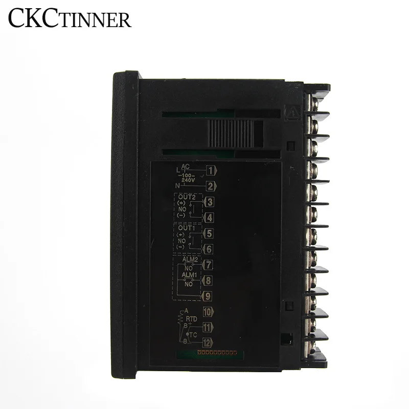
Напряжение питания: 100-240 В переменного тока, 50/60 Гц
Типы входов-термопары K, J, R, S, B, E, N, T
RTD Pt100, Cu50
В настоящее время 0-20mA, 4-20mA
Тип выхода электромагнитное реле, SSR, ток, SCR
Потребляемая мощность: менее 5 ва
Метод управления: PID контроль (с автоматической настройкой) или самонастройка, или ВКЛ/ВЫКЛ
Метод настройки: сенсорный переключатель
Дисплей и светодиодный индикатор
Сигнал тревоги отклонение высокое, низкое, Высокое/низкое, полоса, процесс высокое, низкое значение набора высокое, низкое
Период выборки: 0.5s
Электромагнитная совместимость: IEC61000-4-4 (Электрический быстрый переходный взрыв), 4кВ/5 кГц; IEC61000-4-5 (всплеск), 4кВ
Изоляционное напряжение> = 2300 в среди терминала питания, релейного контакта и сигнала; >= 600 в между двумя изолированными терминалами слабого сигнала
Рабочая температура: от 0 до 50 ℃ (от 32 до 122 ℃)
Рабочая влажность: 30-85% RH макс, без конденсации


Трекер стоимости
История цены
Отзывы покупателей
Новые отзывы о товарах
Отзывы о Цифровой Интеллектуальный промышленный регулятор температуры RH400 PID RKC 220
- Manuals
- Brands
- RKS Manuals
- Temperature Controller
- RZ400
- Instruction manual
-
Contents
-
Table of Contents
-
Troubleshooting
-
Bookmarks
Quick Links
Temperature Controller
RZ100/RZ400
RS100/RS400
Instruction Manual
.
RKC INSTRUMENT INC.
IMR02Y03-E1
®
Summary of Contents for RKS RZ400
-
Page 1
Temperature Controller RZ100/RZ400 RS100/RS400 Instruction Manual RKC INSTRUMENT INC. IMR02Y03-E1 ®… -
Page 2
NOTICE This manual assumes that the reader has a fundamental knowledge of the principles of electricity, process control, computer technology and communications. The figures, diagrams and numeric values used in this manual are only for explanation purpose. RKC is not responsible for any damage or injury that is caused as a result of using this instrument, instrument failure or indirect damage. -
Page 3: Safety Precautions
Safety Precautions Pictorial Symbols (safety symbols) Various pictorial symbols are used in this manual to ensure safe use of the product, to protect you and other people from harm, and to prevent damage to property. The symbols are described below. Be sure you thoroughly understand the meaning of the symbols before reading this manual.
-
Page 4: For Proper Disposal
This product is intended for use with industrial machines, test and measuring equipment. (It is not designed for use with medical equipment and nuclear energy plant.) This is a Class A instrument. In a domestic environment, this instrument may cause radio interference, in which case the user may be required to take additional measures.
-
Page 5: Symbols
Symbols Pictorial Symbols (safety symbols) : This mark indicates important information on installation, handling and operating procedures. : This mark indicates supplemental information on installation, handling and operating procedures. : This mark indicates where additional information may be located. …
-
Page 6: Table Of Contents
Contents Page NOTICE Safety Precautions …………………… i-1 Pictorial Symbols (safety symbols) …………….i-1 WARNING ……………………i-1 CAUTION …………………….. i-2 For Proper Disposal ………………….i-2 Symbols ……………………..i-3 Pictorial Symbols (safety symbols) …………….i-3 Character Symbols ………………….. i-3 …
-
Page 7
The chapter 3 describes wiring cautions, wiring layout and wiring of terminals. 3.1 Wiring Cautions ……………….. 3-2 3.2 Terminal Layout ……………….. 3-5 RZ100/RS100 ………………….3-5 RZ400/RS400 ………………….3-5 Isolations of input and output ………………3-6 3.3 Wiring of Each Terminal …………….3-7 Power supply ………………….3-7 … -
Page 8
Page 5. OPERATION …………..5-1 The chapter 5 describes Operating precautions, Setup procedures and Parameter setting that are required before operation. 5.1 Operating Precautions ……………… 5-2 5.2 Setup Procedures ………………5-4 5.3 Initial Setup before Operation …………… 5-5 5.3.1 Initial setting of setup example 1 (Setting parameters related to the alarm) …. 5-6 5.3.2 Initial setting of setup example 2 (Setting parameters related to the input, control, output and alarm) ……. -
Page 9
Page 9. DISPLAY FUNCTION …………9-1 The chapter 9 describes display related functions, setting contents and setting procedure based on the key words related to Display. 9.1 Releasing the Display Restriction of the Parameters ……..9-2 9.2 Changing the Display Position of STOP during the Control Stop ….9-4 9.3 Hiding the Display of the Set Value (SV) ………… -
Page 10
Page 11. CONTROL FUNCTION ……….11-1 The chapter 11 describes control related functions, setting contents and setting procedure based on the key words related to controls. 11.1 Running/Stopping control (RUN/STOP transfer) ……..11-2 11.2 Changing Control Action …………….11-4 11.3 Setting PID Values Automatically (Autotuning) ……..11-8 11.4 Setting PID Values Automatically (Startup tuning) …….. -
Page 11
Page 13. TROUBLESHOOTING ……….. 13-1 The chapter 13 describes Error displays and countermeasures for errors. 13.1 Error Displays ………………13-2 Input error displays ………………..13-2 Self-diagnostic error ………………..13-3 13.2 Solutions for Problems …………….13-4 Displays ……………………13-5 … -
Page 12
MEMO i-10 IMR02Y03-E1… -
Page 13: Outline
OUTLINE This chapter describes features, package contents, model code, etc. 1.1 Features ………………. 1-2 1.2 Checking the Product …………… 1-3 1.3 Model Code ………………1-4 1.4 Parts Description …………….1-8 1.5 Input/Output and Function Blocks ……….1-10 1.6 Handling Procedure to Operation ……….. 1-11 IMR02Y03-E1…
-
Page 14: Features
1.1 Features This high performance digital controller has the following features: Panel space saving: 60 mm depth (RZ400 and RS400), 63 mm (RZ100 and RS100) Sampling cycle 0.25 seconds Incorporates Autotuning (AT) for easy setting of PID values Automatically calculates the PID values to provide fast stabilization.
-
Page 15: Checking The Product
Check that all of the items delivered are complete. (Refer to below) RZ100/400 Accessories Q’TY Remarks Instrument Mounting bracket (with screw) RZ100/RZ400 Instruction Manual Enclosed with RZ100/400 (for English) (IMR02Y02-E) RS100/400 Accessories Q’TY Remarks Instrument …
-
Page 16: Model Code
Check that the product received is correctly specified by referring to the following model code list: If the product is not identical to the specifications, please contact RKC sales office or the agent. Suffix code RZ100 RZ400 -□ □ □*□ □ □ /□-□ □□□ RS100 (1) (2) (3) (4) (5) (6)
-
Page 17
1. OUTLINE If Quick start code is not specified, control action, input range and outputs are factory configured as follows depending on with or without outputs. With/Without output(s) Factory setting Control Output 1 Output 2 Output 3 Range method Output 1 (OUT1) Output 2 (OUT2) Output 3 (OUT3) (OUT1) -
Page 18
1. OUTLINE Input Range Code Table Thermocouple (TC) input RTD input Input type Code Range Input type Code Range Input type Code Range 0 to 200 C 0 to 300 F 199.9 to 649.0 C Pt100 0 to 400 C 328 to 2192 F 199.9 to 200.0 C 0 to 600 C… -
Page 19: Quick Start Code 2 (Initial Setting Code)
1. OUTLINE Quick start code 2 (Initial setting code) Quick start code 2 tells the factory to ship with each parameter preset to the values detailed as specified by the customer. Quick start code 2 is not necessarily specified when ordering, unless the preset is requested. These parameters are software selectable items and can be re-programmed in the field following procedures found in the manual.
-
Page 20: Parts Description
OUT1 OUT2 OUT3 ALM lamp [Red] RZ100 Set (SET) key Shift key Down key Up key RZ400 8888 Measured value (PV) display [Green] 8888 Set value (SV) display [Orange] AT lamp [Green] OUT1 OUT2 OUT3 RS400 OUT1 to OUT3 lamp [Green]…
-
Page 21: Bottom View
To avoid damage to the instrument, never use a sharp object to press keys. Bottom View Loader communication connector is supplied as standard on RZ100/400 only. RZ100 RZ400 Loader communication connector Loader communication Setting and monitoring on a personal computer (PC) is possible if the controller is connected with…
-
Page 22: Input/Output And Function Blocks
1. OUTLINE 1.5 Input/Output and Function Blocks This section describes the input/output and function blocks of the instrument. : Monitor display Set value : Only RZ100/400 Marked : Optional PV monitor Measured Control processing MV monitor input Control output Input processing …
-
Page 23: Handling Procedure To Operation
1. OUTLINE 1.6 Handling Procedure to Operation After installation and wiring, follow the procedure below to configure settings required for operation. Power ON Conditions specified at time of ordering are acceptable Set operation conditions? To change pre-set conditions Initial Setting Refer to 5.3 Initial Setup before Operation (P.
-
Page 24
MEMO 1-12 IMR02Y03-E1… -
Page 25: Mounting
MOUNTING This chapter describes mounting cautions, dimensions and mounting procedures. 2.1 Mounting Cautions …………….2-2 2.2 Dimensions ………………2-3 2.3 Procedures of Mounting and Removing ……….. 2-4 IMR02Y03-E1…
-
Page 26: Mounting Cautions
2. MOUNTING 2.1 Mounting Cautions To prevent electric shock or instrument failure, always turn off the power before mounting or removing the instrument. (1) This instrument is intended to be used under the following environmental conditions. (IEC61010-1) [OVERVOLTAGE CATEGORY II, POLLUTION DEGREE 2] (2) Use this instrument within the following environment conditions: …
-
Page 27: Dimensions
0.6 Close horizontal mounting 0.6 L1 = 48 n 3 79.1 n = Number of controllers (2 to 6) RZ400/RS400 (Unit: mm) Individual mounting 0.6 25 45 Close horizontal mounting 0.6 L1 = 48 n 3 n = Number of controllers (2 to 6) 70.1…
-
Page 28: Procedures Of Mounting And Removing
The mounting position of the mounting brackets Mounting positions for a single controller RZ100/RS100 RZ400/RS400 * If mounting brackets are installed on the sides of the Waterproof/Dustproof type controller as shown in the figure (marked with *), sufficient Waterproof/Dustproof performance cannot be obtained.
-
Page 29: Mounting Procedures (Standard Type)
2. MOUNTING Mounting procedures (Standard type) 1. Prepare the panel cutout as specified in Fig. 2.1. Fig. 2.1 Panel (Panel thickness: 1 to 10 mm) Refer to 2.2 Dimensions (P. 2-3). Mounting holes Fig. 2.2 2. Insert the instrument through the panel cutout. (Fig. 2.2) Panel 3.
-
Page 30: Mounting Procedures (Waterproof/Dustproof Type) [Only Rz100/400]
2. MOUNTING Mounting procedures (Waterproof/Dustproof type) [Only RZ100/400] The front of the instrument conforms to IP66 [Specify when ordering] when mounted on the panel. For effective Waterproof/Dustproof, the gasket must be securely placed between the instrument and the panel without any gap.
-
Page 31: Removal Procedures
2. MOUNTING Removal procedures 1. Turn the power OFF. Fig. 2.11 2. Remove the wiring. 3. Loosen the screw of the mounting bracket. 4. Remove the mounting bracket by pulling it up (Fig. 2.12 ) Rear of mounting bracket and forward (Fig.
-
Page 32
MEMO IMR02Y03-E1… -
Page 33: Wiring
WIRING This chapter describes wiring cautions, wiring layout and wiring of terminals. 3.1 Wiring Cautions …………….3-2 3.2 Terminal Layout …………….3-5 3.3 Wiring of Each Terminal …………..3-7 3.4 Handling of the Terminal Cover (Optional) ……..3-11 IMR02Y03-E1…
-
Page 34: Wiring Cautions
3. WIRING 3.1 Wiring Cautions To prevent electric shock or instrument failure, do not turn on the power until all wiring is completed. Make sure that the wiring is correct before applying power to the instrument. For thermocouple input, use the appropriate compensation wire. …
-
Page 35: Rz100/Rs100
Top view Panel (RZ100/RS100 is used in the example shown, but restrictions for crossover wiring are the same for RZ400/RS400.) If solderless terminal lugs other than the recommended dimensions are used, terminal screws may not tighten. In that case, bend each solderless terminal lug before wiring.
-
Page 36: Rz400/Rs400
When mounting and removing the terminal cover, apply pressure very carefully to avoid damage to the terminal cover. If a solderless terminal lug touches the RZ400/RS400 common terminal cover, remove the projection from the terminal cover by manually bending it back and forth until it breaks off.
-
Page 37: Terminal Layout
Relay contact/Voltage pulse/Current Current transformer (CT) input 2 (CT2) * Current transformer (CT) input 1 (CT1) * [Refer to P. 3-10] * Optional RZ400/RS400 Power supply voltage [Refer to P. 3-7] 100 to 240 V AC Communication * Output 2 (OUT2) [Refer to P.
-
Page 38: Isolations Of Input And Output
3. WIRING Isolations of input and output For the Input/Output isolation block of this instrument, refer to the following: Power supply Isolated Isolated Isolated Isolated Non-Isolated Output 1 Commu- OUT1 Measured input Isolated Isolated Isolated nication Output 3 Output 2 (RS-485) Non-Isolated OUT3…
-
Page 39: Wiring Of Each Terminal
7.6 VA max. (at 240 V AC) Power supply frequency: 50/60 Hz RZ400/RS400: 5.9 VA max. (at 100 V AC) 8.4 VA max. (at 240 V AC) If there is electrical noise in the vicinity of the instrument that could affect operation, use a noise filter.
-
Page 40: Output 1 (Out1)/Output 2 (Out2)/Output 3 (Out3)
Terminals 5 and 6 are for output 1 (OUT1); Terminals 3 and 4 are for output 2 (OUT2); Terminals 8 and 9 are for output 3 (OUT3). Connect an appropriate load according to the output type. (Specify when ordering) RZ100/RS100 RZ400/RS400 Output 3 (OUT3) Output 2 (OUT2) Output 2 (OUT2)
-
Page 41
RS100 Electrical life: 100,000 times or more (Rated load) Output 3 (OUT3) Control output Mechanical life: 20 million times or more RZ400 Output 3 (OUT3) (Switching: 300 times/min) RS400 Contact type: 1a contact Contact rating (Resistive load): 250 V AC 3 A, 30 V DC 1 A… -
Page 42: Current Transformer (Ct) Input (Optional)
Current transformer (CT) input (optional) Models that were specified with a current transformer (CT) when ordering can use the following terminal numbers. RZ100/RS100: Terminal No. 16 to 18 (CT1, CT2) RZ400/RS400: Terminal No. 22 to 24 (CT1, CT2) RZ100/RS100 RZ100/RS100 CT input…
-
Page 43: Handling Of The Terminal Cover (Optional)
Terminal cover RZ100/RS100 terminal cover RZ400/RS400 common terminal cover Protrusions Drawing of RZ100/RS100 with terminal caver Drawing of RZ400/RS400 with terminal caver This section of RZ400/RS400 terminal cover can be removed by bending it. Remove unnecessary part(s) depending on the wiring condition.
-
Page 44
3. WIRING Removal procedures Release the protrusions of terminal cover from the insertion slots () shown in the following figure, and then pull the terminal cover () to remove it from the case. 3-12 IMR02Y03-E1… -
Page 45: Basic Operation And Parameter List
BASIC OPERATION PARAMETER LIST This chapter describes basic operations, different types of modes, switching between modes, and changing/storing the set values. 4.1 Mode Types and Switching ………….. 4-2 4.1.1 Switching between modes …………..4-2 4.1.2 Input type and input range display …………4-3 4.2 Parameter Types and Switching …………
-
Page 46: Mode Types And Switching
4. BASIC OPERATION AND PARAMETER LIST 4.1 Mode Types and Switching 4.1.1 Switching between modes The instrument has five different modes. Modes can be switched through key operations of keys. Power ON Input type/Input range display (Refer to P. 4-3) Automatically (in 4 seconds) Monitor display mode SV setting mode…
-
Page 47: Input Type And Input Range Display
4. BASIC OPERATION AND PARAMETER LIST 4.1.2 Input type and input range display As soon as this instrument is powered on, input type and input range will be displayed. Example: When sensor type is K thermocouple (0 to 400 C) Power ON Input symbol Table 1: Input type symbol…
-
Page 48: Parameter Types And Switching
4. BASIC OPERATION AND PARAMETER LIST 4.2 Parameter Types and Switching 4.2.1 Scrolling through parameters The diagram below shows operating navigation. Parameters not included in the specification will not be displayed. : Press : Press (P. 4-9) (P. 4-8) (P. 4-8) Communication setting Power ON モニタ表示モード…
-
Page 49
4. BASIC OPERATION AND PARAMETER LIST : Press : Press (P. 4-10) Initial setting mode Parameter setting mode Alarm 1 set value (ALM1) Proportional band Initial setting code Alarm 1 set value (ALM1) [high] [heat-side] Fine tuning Code No.: 0000 CAL1 0001 0000… -
Page 50
4. BASIC OPERATION AND PARAMETER LIST : Press : Press Initial setting mode Initial setting code Initial setting code Initial setting code Initial setting code Initial setting code Code No.: 0001 Code No.: 0002 Code No.: 0003 Code No.: 1021 Code No.: 1030 0000 1041… -
Page 51
4. BASIC OPERATION AND PARAMETER LIST : Press : Press Initial setting mode Initial setting code Initial setting code Initial setting code Initial setting code Initial setting code Code No.: 1041 Code No.: 1042 Code No.: 1045 Code No.: 1051 Code No.: 1052 1030 1041… -
Page 52: Parameter List
4. BASIC OPERATION AND PARAMETER LIST 4.2.2 Parameter list Monitor display mode Factory Symbol Name Display range Page set value PV/SV monitor PV display unit: Measured range low (5 % of Measured range) to Measured range high (5 % of Measured range) For a range with a decimal point, the maximum display range is 199.9 to 999.9.
-
Page 53: Communication Setting Mode
4. BASIC OPERATION AND PARAMETER LIST Communication setting mode Factory Symbol Name Data range Page set value CMPS Communication protocol 0: RKC communication 12-8 Communication Protocol specified 1: Modbus at the time of ordering. RKC communication: 0 to 99 Device address 12-8 communication:…
-
Page 54: Parameter Setting Mode
4. BASIC OPERATION AND PARAMETER LIST Parameter setting mode Factory Symbol Name Data range Page set value 1999 to 9999 or 199.9 to 999.9 Alarm 1 set value (ALM1) 10 or 10.0 5-13 (Unit: C [F]) Alarm 1 set value (ALM1) [high] 10-2 10 or 10.0 AL1`…
-
Page 55
4. BASIC OPERATION AND PARAMETER LIST Factory Symbol Name Data range Page set value Proportional band [cool-side] 1 to 1000 % of Proportional band [heat-side] 11-24 (ON/OFF action of cool-side only is not possible.) 10 to 10 or 10.0 to 10.0 Overlap/Deadband 0 or 0.0 11-24… -
Page 56: Initial Setting Mode
4. BASIC OPERATION AND PARAMETER LIST Initial setting mode Factory Symbol Name Data range Page set value Initial setting code This is the first parameter symbol of Initial setting code 0000 0000 0000: TC input K 1000: TC input S Input type When input range 0001: TC input J…
-
Page 57
4. BASIC OPERATION AND PARAMETER LIST Factory Symbol Name Data range Page set value ALM2 Alarm 2 type 0: None When alarm code is 10-8 1: Deviation high specified at the time of ordering, 2: Deviation high/low the Alarm type in 3: Process high the alarm code is 5: Deviation low… -
Page 58
4. BASIC OPERATION AND PARAMETER LIST Factory Symbol Name Data range Page set value oAL1 Output assignment of 0: No assignment When Alarm output Alarm 1 assignment is 1: Output 1 (OUT1) * specified at the time 2: Output 2 (OUT2) * of ordering, the 3: Output 3 (OUT3) ordered output… -
Page 59
4. BASIC OPERATION AND PARAMETER LIST Factory Symbol Name Data range Page set value Setting limiter low Input range low to Setting limiter high Input range low Varies with the setting of the Decimal point position. dSoP PV flashing display at input 0: Flashing display 6-10 error… -
Page 60
4. BASIC OPERATION AND PARAMETER LIST Factory Symbol Name Data range Page set value Initial setting code This is the first parameter symbol of Initial setting code 1045 1045 CTr1 CT1 ratio 1 to 1000 When CTL-6-P-N 10-40 is specified at the Set the following value depending on the CT type. -
Page 61
4. BASIC OPERATION AND PARAMETER LIST Factory Symbol Name Data range Page set value Control output at burnout 0: Result of control computation PID control: 6-10 1: PID control: Output limiter low (output OFF) Heat/Cool PID control: 5.0 % (output OFF) * Heat/Cool PID control: * Both heating and cooling outputs are forced OFF. -
Page 62: Changing Set Value
4. BASIC OPERATION AND PARAMETER LIST 4.3 Changing Set Value The highlighted digit indicates which digit can be set. Press key to go to a different digit. Every time key is pressed, the highlighted digit moves as follows. 8.8.8.8 Highlighted …
-
Page 63: Protecting Setting Data
4. BASIC OPERATION AND PARAMETER LIST 4.4 Protecting Setting Data To protect setting data in the instrument, the setting data can be locked so that no changes can be made (Set data lock function). The Set data lock function uses the lower three digits of the set value to restrict the setting in the SV setting mode, the Parameter setting mode, and the Communication setting mode.
-
Page 64
MEMO 4-20 IMR02Y03-E1… -
Page 65: Operation
OPERATION This chapter describes Operating precautions, Setup procedures and Parameter setting that are required before operation. 5.1 Operating Precautions …………..5-2 5.2 Setup Procedures …………….5-4 5.3 Initial Setup before Operation …………5-5 5.3.1 Initial setting of setup example 1 (Setting parameters related to the alarm) ……….
-
Page 66: Operating Precautions
5. OPERATION 5.1 Operating Precautions Before starting the operation, check the following items. Power ON As soon as the instrument is powered up, operation is started after the display of the input type and the input range. Action at input error In case of input failure this instrument provides the following behaviors and output.
-
Page 67
5. OPERATION Alarm hold action The Alarm hold action is activated when the power is turned on or when transferred from STOP mode to RUN mode. (in case of “with hold action”) The Alarm re-hold action is activated when not only the Set value (SV) is changed, but also the power is turned on or when transferred from STOP mode to RUN mode. -
Page 68: Setup Procedures
5. OPERATION 5.2 Setup Procedures Setup the controller prior to operating the instrument. Refer to the following setup example. Setup example 1 Setup example 2 Thermocouple (K), 0 to 400 C RTD (Pt100), 0.0 to 300.0 C Input: Input: Control: PID control with AT (reverse action) Control: Heat/Cool PID control with AT (air cooling) Output: Control output: Uses Output 1 (OUT1) Output: Control output: Heat-side: Uses Output 1 (OUT1)
-
Page 69: Initial Setup Before Operation
5. OPERATION 5.3 Initial Setup before Operation Before starting the operation, confirm that the set value of the parameter matches the model code as specified when ordered. Parameters which were not specified when ordered must be set before use. Some functions may need to be set in the Initial setting mode. Read the following part before attempting the setting.
-
Page 70: Initial Setting Of Setup Example
5. OPERATION 5.3.1 Initial setting of setup example 1 (Setting parameters related to the alarm) In the Setup example 1 (refer to P. 5-4), all default factory set values except alarm related parameters can be used in actual applications without any changes. This section describes the Initial setting of the alarm related operation used in the Setup example 1.
-
Page 71
5. OPERATION From Cod 0000 Initial setting mode Display mode selection Initial setting code 1Cod dSEL 0003 0001 Set “1: Expanded display mode” 3 times Initial setting mode Alarm 1 action Alarm 1 timer at input burnout Initial setting code Alarm 1 differential gap ALT1 1Cod… -
Page 72: (Setting Parameters Related To The Input, Control, Output And Alarm)
5. OPERATION 5.3.2 Initial setting of setup example 2 (Setting parameters related to the input, control, output and alarm) The setup example 2 (refer to P. 5-4) describes the initial setting of input, control, output and alarm action. Setup example 2: RTD (Pt100), 0.0 to 300.0 C Input: Control: Heat/Cool PID control with AT (air cooling)
-
Page 73
5. OPERATION From Parameter setting mode Initial setting mode Initial setting code Input type Decimal point position Input range high 1Cod 1InP PGdP PGSH 0000 1100 0001 300. Set Input type. Set Decimal point Set Input range high position 300.0 1100: RTD input 1: One decimal place [Setting range:… -
Page 74
5. OPERATION From Cod 0003 Initial setting mode Setting limiter high Setting limiter low Initial setting code Temperature unit 1Cod UnIT dSLH dSLL 3 times 1021 0001 300. 000. Set Temperature unit Set Setting limiter high Set Setting limiter low 1: C 300.0 [Setting range:… -
Page 75
5. OPERATION From Cod 1042 Initial setting mode Cool action Control output at burnout Initial setting code Control action UOSc 0obo 1Cod UnXE 3 times 0000 0000 1051 0001 Set Control output at Set Cool action Set Control action burnout 0: Air cooling 1: Heat/Cool PID control 0: Result of control… -
Page 76: Setting The Control Set Value [Set Value (Sv)]
5. OPERATION 5.4 Setting the Control Set Value [Set value (SV)] After finishing the initial settings, set the control target value, SV. [Setting example: Set the set value (SV) to 200 C.] Switch the display to the Set value (SV) setting mode …
-
Page 77: Setting The Alarm Set Value
5. OPERATION 5.5 Setting the Alarm Set Value After finishing the initial settings, set the alarm set values if they are used. [Setting example: Set the Alarm 1 set value (ALM1) to 20 C.] Switch the mode to the Parameter setting mode [Switch the screen to Alarm 1 set value (ALM1)] …
-
Page 78: Tuning The Pid Parameters (Execution Of At)
5. OPERATION 5.6 Tuning the PID Parameters (Execution of AT) Suitable PID values are automatically calculated by Autotuning (AT) function. The Autotuning (AT) function automatically measures, computes and sets the optimum PID values. Before starting the Autotuning, make sure that all required conditions to start the AT are satisfied. (Refer to 11.3 Setting PID Values Automatically (Autotuning) [P.
-
Page 79
5. OPERATION When canceling the Autotuning (AT) function, press the key to be set to “0: PID control” with the Autotuning (AT) screen. To return to the PV/SV monitor, press and hold the key for 2 seconds or more. If no key operation is performed within 1 minute, the display returns to the PV/SV monitor screen. If the Autotuning (AT) is not completed yet at this moment, the Autotuning (AT) continues even after the display has returned to the PV/SV monitor. -
Page 80
MEMO 5-16 IMR02Y03-E1… -
Page 81: Input Function
INPUT FUNCTION This chapter describes input related functions, setting contents and setting procedure based on the key words related to inputs. 6.1 Changing Input …………….. 6-2 6.2 Correcting Input …………….6-7 6.3 Removing Input Noise …………..6-8 6.4 Changing Error Handling at Input Error ………. 6-10 IMR02Y03-E1…
-
Page 82: Changing Input
6. INPUT FUNCTION 6.1 Changing Input Measured input can be changed at following parameters. Set the input according to the sensor and the application. Input type Decimal point position Input range high/Input range low Temperature unit …
-
Page 83
6. INPUT FUNCTION Parameter setting Refer to the Measured range table (P. 6-5) for the measured range of each input type. For the input range code, refer to Input range code table (P. 6-5). Input type Cod 0000 [Initial setting mode: Parameter symbol Data range… -
Page 84
6. INPUT FUNCTION Input range low Cod 0000 [Initial setting mode: Parameter symbol Data range Factory set value PGSL Measured range low to (Input range high 1 digit) When input range code is specified at the time of Varies with the setting of the Decimal point position. -
Page 85
6. INPUT FUNCTION Measured range table TC input RTD input Input type Measured range Input type Measured range 200 to 1372 C 328 to 2502 F 200 to 649 C 328 to 1200 F Pt100 199.9 to 400.0 C 100.0 to 752.0 F 199.9 to 649.0 C 199.9 to 999.9 F… -
Page 86
6. INPUT FUNCTION Setting procedure Input type, Decimal point position and Input range high/low can be set at Cod 0000 in the Initial setting mode. Temperature unit can be set at Cod 1021 in the Initial setting mode. Procedure to enter the Initial setting mode Monitor display mode Parameter setting mode… -
Page 87: Correcting Input
RZ400 [A]: 200 C RZ400 [B]: 198 C To correct the Measure value (PV) of RZ400 [B], add bias of 2 C by PV bias: Displayed value = Measured value (PV) + PV bias 198 C 2 C 200 C Level (Temperature) 200 C…
-
Page 88: Removing Input Noise
6. INPUT FUNCTION 6.3 Removing Input Noise To remove input noise influence, first-order delay PV digital filter is available. Description of function PV digital filter is software designed to reduce variance of PV caused by noise. Effect of Input noise can be reduced by setting time constant of PV digital filter based on the controlled object requirement and its level of noise.
-
Page 89
6. INPUT FUNCTION Setting procedure PV digital filter can be set in the Parameter setting mode. To show the PV digital filter, enter the Expanded display mode by setting the “Display mode selection” at Cod 0003 in the Initial setting mode. Procedure to enter the Initial setting mode Monitor display mode Parameter setting mode… -
Page 90: Changing Error Handling At Input Error
6. INPUT FUNCTION 6.4 Changing Error Handling at Input Error PV flashing display at input error, Control output at burnout and Alarm action at input burnout can be set. Description of function When the Measured value (PV) exceeds the input range high limit or goes below the input range low limit, action is switched to the one specified in the Selection of control output at input burnout.
-
Page 91
6. INPUT FUNCTION Parameter setting PV flashing display at input error Cod 1021 [Initial setting mode: Parameter symbol Data range Factory set value DSOP 0: Flashing display 1: Non-flashing display To show the “PV flashing display at input error,” enter the Expanded display mode by setting the “Display mode selection”… -
Page 92
6. INPUT FUNCTION Setting procedure PV flashing display at input error can be set at Cod 1021 in the Initial setting mode. Alarm 1 output action at input burnout can be set at Cod 1041 in the Initial setting mode. … -
Page 93
6. INPUT FUNCTION Initial setting mode Alarm 1 action Initial setting code at input burnout 1Cod Abo1 To end setting Twice 1041 0003 Set Alarm 1 action at input burnout To continue setting To continue 3 times setting Press a few times depending on the setting item Go to one of following… -
Page 94
MEMO 6-14 IMR02Y03-E1… -
Page 95: Output Function
OUTPUT FUNCTION This chapter describes output related functions, setting contents and setting procedure based on the key words related to outputs. 7.1 Changing Output Assignment …………7-2 7.2 Limiting Output …………….. 7-6 7.3 Changing Proportional Cycle Time ……….7-8 7.4 Changing Alarm Output (Energize/De-energize) ……7-12 7.5 Monitoring Manipulated Output Value ……….
-
Page 96: Changing Output Assignment
Assign outputs [control output, alarm output, heater break alarm (HBA) output] to the output terminals. When assigning outputs, assign Control output(s) first. Then, assign Alarm output and Heater break alarm (HBA) output. Refer to the following table for available assignments. Output terminals RZ400/RS400 RZ100/RS100 ① ①…
-
Page 97
Contact rating (Resistive load): 250 V AC 3 A, 30 V DC 1 A RS100 Control Output 3 (OUT3) Electrical life: 100,000 times or more (Rated load) output RZ400 Mechanical life: 20 million times or more Output 3 (OUT3) (Switching: 300 times/min) RS400 Contact type:… -
Page 98
7. OUTPUT FUNCTION Output assignment of Alarm 1, 2 Cod 0002 [Initial setting mode: Parameter symbol Data range Factory set value OAL1 0: No assignment When Alarm output assignment is 1: Output 1 (OUT1) specified at the time of ordering, the OAL2 2: Output 2 (OUT2) ordered output assignment is the… -
Page 99
7. OUTPUT FUNCTION Setting procedure Control output assignment, Output assignment of Alarm and Output assignment of Heater break alarm can Cod 0002 be set at in the Initial setting mode. Procedure to enter the Initial setting mode Monitor display mode Parameter setting mode PV/SV monitor Alarm 1 set value… -
Page 100: Limiting Output
7. OUTPUT FUNCTION 7.2 Limiting Output Use output limiter to limit the output. Description of function This is the function which restricts the high and low limits of Manipulated output values (MV). Manipulated output value (MV) 105.0 % The manipulated output value is not produced within this range.
-
Page 101
7. OUTPUT FUNCTION Setting procedure Output limiter high/low can be set in the Parameter setting mode. To show the “Output limiter high/low,” enter the Expanded display mode by setting the “Display mode selection” at Cod 0003 in the Initial setting mode. Procedure to enter the Initial setting mode Monitor display mode Parameter setting mode… -
Page 102: Changing Proportional Cycle Time
7. OUTPUT FUNCTION 7.3 Changing Proportional Cycle Time When time proportioning output (relay output or voltage pulse output) is specified at the time of ordering, proportional cycle and Minimum ON/OFF time can be changed. Description of function Proportional cycle time PV change Manipulated output value turns ON and OFF in Proportional…
-
Page 103
7. OUTPUT FUNCTION Parameter setting Proportional cycle time [heat-side] [Parameter setting mode] Parameter symbol Data range Factory set value 88PT 1 to 100 seconds Relay contact output: 20 Voltage pulse output: 2 To show the “Proportional cycle time [heat-side],” specify time proportioning output (relay contact output or voltage pulse output) on the heat-side control output. -
Page 104
7. OUTPUT FUNCTION Minimum ON/OFF time of proportioning cycle [cool-side] [Parameter setting mode] Parameter symbol Data range Factory set value 0 to 1000 ms To show the “Minimum ON/OFF time of proportioning cycle [cool-side],” specify time proportioning output (relay contact output or voltage pulse output) on the cool-side control output. To show the “Minimum ON/OFF time of proportioning cycle [cool-side],”… -
Page 105
7. OUTPUT FUNCTION Minimum ON/OFF time of proportioning cycle Minimum ON/OFF time of proportioning cycle can be set in the Parameter setting mode. To show the “Minimum ON/OFF time of proportioning cycle,” enter the Expanded display mode by setting the “Display mode selection”… -
Page 106: Changing Alarm Output (Energize/De-Energize)
7. OUTPUT FUNCTION 7.4 Changing Alarm Output (Energize/De-energize) Energize or De-energize can be selected for Alarm outputs and Heater break alarm (HBA) outputs (optional). Energize or De-energize can be set on the output terminals (OUT1 to OUT3) which were configured at Cod 0002 in the Initial setting mode for “Output assignment of Alarm 1 and 2” and “Output assignment of Heater break alarm 1 and 2.”…
-
Page 107
7. OUTPUT FUNCTION Output 2 (OUT2) energize/de-energize when assigned to alarm Cod 0002 [Initial setting mode: Parameter symbol Data range Factory set value EXC2 0: Energize 1: De-energize (Contact CLOSE or OPEN, at STOP) * 2: De-energize (Contact OPEN, at STOP) * If the controller is not in the alarm state at STOP, contact CLOSE. -
Page 108
7. OUTPUT FUNCTION Setting procedure Cod 0002 Output energize/de-energize when assigned to alarm can be set at in the Initial setting mode. Procedure to enter the Initial setting mode Monitor display mode Parameter setting mode PV/SV monitor Alarm 1 set value Set data lock 1328 1AL1… -
Page 109: Monitoring Manipulated Output Value
7. OUTPUT FUNCTION 7.5 Monitoring Manipulated Output Value Manipulated output value can be monitored on this instrument. Display contents Manipulated output value [heat-side] [Monitor display mode] Parameter symbol Data range Factory set value PID control: Output limiter low to Output limiter high Heat/Cool PID control: 5.0 % to Heat-side output limiter (high) To show the “Manipulated output value [heat-side],”…
-
Page 110
7. OUTPUT FUNCTION Display operation Manipulated output value can be found in the Minitor display mode. To show the “Manipulated output value,” enter the Expanded display mode by setting the “Display mode selection” at Cod 0003 in the Initial setting mode. Procedure to enter the Initial setting mode Monitor display mode Parameter setting mode… -
Page 111: Setting And Key Operation
SETTING KEY OPERATION This chapter describes display related functions, setting contents and setting procedure based on the keywords related to setting and key operation. 8.1 Limiting the Setting Range of Set Value (SV) ……..8-2 8.2 Continuing the Control when Entering the Initial Setting Mode ..8-5 8.3 Restricting Key Operation …………..
-
Page 112: Limiting The Setting Range Of Set Value (Sv)
8. SETTING AND KEY OPERATION 8.1 Limiting the Setting Range of Set Value (SV) To limit the setting range of the Set value (SV), Setting limiter is used. Description of function Setting limiter is a function to limit the setting range of the Set value (SV) within the input range. Example: The input range is from 200 to 1372 C, the Setting limiter high is 400 C, and the Setting limiter low is 0 C.
-
Page 113
8. SETTING AND KEY OPERATION Setting limitter high is initialized to the input range high value when the input range is changed. Similarly when setting limiter low is changed, it is initialized to the value of Input range low. [Example] Assuming that the setting limiter high is set to 200 ºC and the setting limiter low is set to 50 ºC on the instrument with a range of 0 to 400 ºC, changing the input range high to 300 ºC will initialize the setting limiter high to the value same as the input range high (300 ºC). -
Page 114
8. SETTING AND KEY OPERATION Setting procedure Cod 1021 Setting limiter high/low can be set at in the Initial setting mode. Procedure to enter the Initial setting mode Monitor display mode Parameter setting mode PV/SV monitor Alarm 1 set value Set data lock 1328 1AL1… -
Page 115: Continuing The Control When Entering The Initial Setting Mode
8. SETTING AND KEY OPERATION 8.2 Continuing the Control when Entering the Initial Setting Mode With the factory setting, the instrument is configured to automatically stop the control (STOP) when the instrument is switched to the Initial setting mode. With another setting, the instrument can continue the control (RUN) even if the instrument is switched to the Initial setting mode.
-
Page 116
8. SETTING AND KEY OPERATION Parameter setting STOP function at Initial setting mode Cod 1030 [Initial setting mode: Parameter symbol Data range Factory set value 0: STOP in the Initial setting mode 1: RUN/STOP continues in the Initial setting mode To show the “STOP function at Initial setting mode,”… -
Page 117: Restricting Key Operation
8. SETTING AND KEY OPERATION 8.3 Restricting Key Operation The set data lock function limits access of unauthorized personnel to the parameters and prevents parameter change by mistake. Description of function The Set data lock function uses the lower three digits of the set value to restrict the setting in the SV setting mode, the Parameter setting mode, and the Communication setting mode.
-
Page 118
8. SETTING AND KEY OPERATION The display status of the Set value (SV) depends on the following items; Lock/unlock of the Set value (SV), Show SV/Hide SV” setting at Cod1021 in the Initial setting mode, Selection of STOP display at Cod1030 in the Initial setting, and … -
Page 119
8. SETTING AND KEY OPERATION Parameter setting Set data lock [Parameter setting mode] Parameter symbol Data range Factory set value 0000 0 or 1 is settable at each digit. 00000 SV display unit Parameters in the Parameter setting mode and the Communication setting mode excluding the Set value (SV) and Alarm set values (ALM1, ALM2) 0: Unlock… -
Page 120
MEMO 8-10 IMR02Y03-E1… -
Page 121: Display Function
DISPLAY FUNCTION This chapter describes display related functions, setting contents and setting procedure based on the key words related to Display. 9.1 Releasing the Display Restriction of the Parameters ……. 9-2 9.2 Changing the Display Position of STOP during the Control Stop ..9-4 9.3 Hiding the Display of the Set Value (SV) ………
-
Page 122: Releasing The Display Restriction Of The Parameters
9. DISPLAY FUNCTION 9.1 Releasing the Display Restriction of the Parameters This instrument has two display modes; “Standard display mode” and “Expanded display mode.” The instrument is shipped from the factory with the factory setting of “Standard display mode.” Switch the mode to “Expanded display mode”…
-
Page 123
9. DISPLAY FUNCTION Parameter setting Display mode selection Cod 0003 [Initial setting mode: Parameter symbol Data range Factory set value dSEL 0: Standard display mode 1: Expanded display mode Setting procedure Cod 0003 Display mode selection can be set at in the Initial setting mode. -
Page 124: Changing The Display Position Of Stop During The Control Stop
(Factory set value) OUT1 OUT2 OUT3 OUT1 OUT2 OUT3 In the above figure RZ400 is used for explanation, but the operation is the same for RZ100/RS100/RS400. Parameter setting STOP display selection Cod 1030 [Initial setting mode: Parameter symbol…
-
Page 125
9. DISPLAY FUNCTION Continued from the previous page. Initial setting mode Initial setting code Display mode selection 1Cod 1Cod dSEL 3 times 0000 0003 0001 Set “1: Expanded display mode” Twice Initial setting mode Initial setting code STOP display selection 1Cod SPCH Twice… -
Page 126: Hiding The Display Of The Set Value (Sv)
8200 OUT1 OUT2 OUT3 OUT1 OUT2 OUT3 Display off In the above figure RZ400 is used for explanation, but the operation is the same for RZ100/RS100/RS400. Parameter setting Show/Hide SV display Cod 1021 [Initial setting mode: Parameter symbol…
-
Page 127
9. DISPLAY FUNCTION Continued from the previous page. Initial setting mode Initial setting code Display mode selection 1Cod 1Cod dSEL 3 times 0000 0003 0001 Set “1: Expanded display mode” Initial setting mode Initial setting code Show/Hide SV display SdSV 1Cod 5 times Setting End… -
Page 128
MEMO IMR02Y03-E1… -
Page 129: Alarm Function
ALARM FUNCTION This chapter describes alarm related functions, setting contents and setting procedure based on the key words related to alarms. 10.1 Using Alarm Function …………..10-2 10.1.1 Setting procedure for alarm function ……….10-2 10.1.2 Changing alarm type ……………. 10-8 10.1.3 Setting a differential gap in alarm action ……..
-
Page 130: Using Alarm Function
10. ALARM FUNCTION 10.1 Using Alarm Function 10.1.1 Setting procedure for alarm function Set alarm as follows: Set the Alarm type. Set the Alarm type For alarm type, refer to 10.1.2 Changing alarm type (P. 10-8). Set the parameter related to Alarm output. Set the parameter …
-
Page 131: Setting Example: Set The Alarm 1 (Model Code: Rz100-Mnm*Nnn/N)
To stop the control when switching the Initial setting mode, refer to 8.2 Continuing the Control when Entering the Initial Setting Mode (P. 8-5). In the following procedure RZ100 is used for explanation, but the operation is the same for RZ400/RS100/RS400. [Setting procedure] Enabling parameter to be set…
-
Page 132
10. ALARM FUNCTION Initial setting mode Initial setting mode Parameter setting mode (Initial setting code screen) (Display mode selection screen) (Alarm 1 set value screen) 8AL1 8CoD 8CoD dSEL 001. 000. 000. 000. OUT1 OUT2 OUT3 OUT1 OUT2 OUT3 OUT1 OUT2 OUT3 OUT1… -
Page 133
10. ALARM FUNCTION Setting up alarm output Initial setting mode Initial setting mode Initial setting mode (Alarm 2 type screen) (Initial setting code screen) (Output assignment of Alarm 1) ALM2 oAL1 8CoD 8CoD 000. 000. 000. 000. OUT1 OUT2 OUT3 OUT1 OUT2… -
Page 134
10. ALARM FUNCTION Setting up Alarm 1 Initial setting mode Initial setting mode Initial setting mode (STOP display selection screen) (Initial setting code screen) (Alarm 1 differential gap screen) SPCH 8CoD 8CoD SAH1 000. 103. 104. 1 000. OUT1 OUT2 OUT3 OUT1… -
Page 135
10. ALARM FUNCTION Setting up Alarm 1 set value Parameter setting mode Initial setting mode Monitor display mode (Alarm 1 set value screen) (Initial setting code screen) (PV/SV monitor screen) 8CoD 8828 8AL1 8AL1 104. 1 888. 001. 010. OUT1 OUT2 OUT3… -
Page 136: Changing Alarm Type
10. ALARM FUNCTION 10.1.2 Changing alarm type There are 21 types of alarm in total. Deviation high Deviation high with hold action Deviation high with re-hold action Deviation low Deviation low with hold action Deviation low with re-hold action …
-
Page 137
10. ALARM FUNCTION Deviation high/low Two types of Deviation high/low action are available. Without high/low individual setting: When the absolute deviation PV – SV is more/less than the Alarm set values, the alarm ON occurs. With high/low individual setting: High action: When the deviation (PV – SV) is more than the Alarm set value [high], the alarm ON occurs. Low action: When the deviation (PV –… -
Page 138
10. ALARM FUNCTION Set value action When the Set value (SV) reaches the Alarm set value, alarm ON occurs. ON: Alarm action turned on : Alarm set value ☆: Alarm differential gap) OFF: Alarm action turned off ( : Set value (SV) SV high When the Set value (SV) is more than the Alarm set values, the alarm ON occurs. -
Page 139
10. ALARM FUNCTION Re-hold action When Re-hold action is ON, the alarm action is also suppressed at the control set value (SV) change until the Measured value (PV) has entered the non-alarm range. Action condition Hold action Re-hold action When the power is turned on With function With function… -
Page 140
10. ALARM FUNCTION Parameter setting Alarm 1 and 2 type Cod 0000 [Initial setting mode: Parameter symbol Data range Factory set value ALM1 When alarm code is specified at the 0: None Deviation high time of ordering, the Alarm type in ALM2 Deviation high/low the alarm code is the factory setting. -
Page 141
10. ALARM FUNCTION Setting procedure Cod 0000 Alarm type can be set at in the Initial setting mode. Procedure to enter the Initial setting mode Monitor display mode Parameter setting mode PV/SV monitor Alarm 1 set value Set data lock 1328 1AL1 1LCK… -
Page 142: Setting A Differential Gap In Alarm Action
10. ALARM FUNCTION 10.1.3 Setting a differential gap in alarm action Description of function It prevents chattering of alarm output due to the Measured value (PV) fluctuation around the Alarm set value. Alarm set Differential gap value Differential gap Alarm set value Time…
-
Page 143
10. ALARM FUNCTION Setting procedure Alarm 1 differential gap can be set at Cod 1041 in the Initial setting mode. Alarm 2 differential gap can be set at Cod 1042 in the Initial setting mode. Procedure to enter the Initial setting mode Monitor display mode Parameter setting mode PV/SV monitor… -
Page 144: Preventing Alarm From Turning On Due To A Transient Abnormal Input
10. ALARM FUNCTION 10.1.4 Preventing alarm from turning on due to a transient abnormal input Alarm timer can be used to prevent alarm from turning on for the alarm state shorter than the set time. Description of function When an alarm condition becomes ON, the output is suppressed until the Alarm timer set time elapses. If the alarm output is still ON after the time is up, the output will resume.
-
Page 145
10. ALARM FUNCTION Parameter setting Alarm 1 and 2 timer Cod 1041 Cod 1042 [Initial setting mode: Parameter symbol Data range Factory set value ALT1 0 to 600 seconds ALT2 To show the “Alarm 1 timer” and “Alarm 2 timer,” enter the Expanded display mode by setting the “Display mode selection”… -
Page 146
10. ALARM FUNCTION Continued from the previous page. Initial setting mode Initial setting code Alarm 1 timer 1Cod ALT1 To end setting 3 times 1041 0000 Set Alarm 1 timer To continue To continue setting Twice setting Initial setting mode Initial setting code Alarm 2 timer 1Cod… -
Page 147: Keeping The Alarm State (Interlock Function)
10. ALARM FUNCTION 10.1.5 Keeping the alarm state (Interlock function) Description of function The Alarm interlock function holds the alarm state even if the Measured value (PV) is out of the alarm zone after it enters the alarm zone once. Example: When the Alarm interlock function is used for Deviation high Measured value (PV) Alarm interlock…
-
Page 148
10. ALARM FUNCTION Setting procedure Alarm 1 interlock can be set at Cod 1041 in the Initial setting mode. Alarm 2 interlock can be set at Cod 1042 in the Initial setting mode. Procedure to enter the Initial setting mode Monitor display mode Parameter setting mode PV/SV monitor… -
Page 149: Releasing The Alarm State (Interlock Release)
10. ALARM FUNCTION 10.1.6 Releasing the alarm state (Interlock release) Description of function The Alarm interlock function holds the alarm state even if the Measured value (PV) is out of the alarm zone after it enters the alarm zone once. In case of Control loop break alarm (LBA), once the LBA has turned ON, the LBA ON state is kept even if LBA OFF conditions are met.
-
Page 150
10. ALARM FUNCTION Parameter setting Interlock release [SV setting mode] Parameter symbol Data range Factory set value oFF: Interlock release on: Interlock state To show the “Interlock release (ILr),” “Interlock” parameter must be set to “on: Used” at any one of “Alarm 1 interlock”… -
Page 151: Using Control Loop Break Alarm (Lba)
10. ALARM FUNCTION 10.2 Using Control Loop Break Alarm (LBA) Setting procedure for control loop break alarm (LBA) Control loop break alarm (LBA) is one of alarm functions. Because of this reason, many of the setting items for Control loop break alarm (LBA) are common to the alarm function. However, it should be noted that Control loop break alarm (LBA) can be assigned to Alarm 2 only.
-
Page 152: Setting Example: Setting Control Loop Break Alarm (Lba) On Alarm
To stop the control when switching the mode to the Initial setting, refer to 8.2 Continuing the Control when Entering the Initial Setting Mode (P. 8-5). In the following procedure RZ100 is used for explanation, but the operation is the same for RZ400/RS100/RS400. [Setting procedure] Enabling parameter to be set…
-
Page 153
10. ALARM FUNCTION Initial setting mode Initial setting mode Parameter setting mode (Initial setting code screen) (Display mode selection screen) (Alarm 1 set value screen) 8AL1 8CoD 8CoD dSEL 001. 000. 000. 000. OUT1 OUT2 OUT3 OUT1 OUT2 OUT3 OUT1 OUT2 OUT3 OUT1… -
Page 154
10. ALARM FUNCTION Setting up alarm output Initial setting mode Initial setting mode (Initial setting code screen) (Output assignment of Alarm 1) 8CoD 8CoD oAL1 oAL1 000. 000. 000. 000. OUT1 OUT2 OUT3 OUT1 OUT2 OUT3 OUT1 OUT2 OUT3 OUT1 OUT2 OUT3… -
Page 155
10. ALARM FUNCTION Setting up Alarm 2 Initial setting mode Initial setting mode (Alarm 2 action (Initial setting code screen) at input burnout screen) 8CoD 8CoD Abo2 Abo2 000. 104. 1 000. 000. OUT1 OUT2 OUT3 OUT1 OUT2 OUT3 OUT1 OUT2 OUT3… -
Page 156
10. ALARM FUNCTION Setting up Control loop break alarm (LBA) set value Parameter setting mode Initial setting mode Monitor display mode (Control loop break alarm time screen) (Initial setting code screen) (PV/SV monitor screen) 8CoD 8828 8LbA 8LbA 104. 1 888. -
Page 157
10. ALARM FUNCTION Description of function The Control loop break alarm (LBA) function is used to detect a load (heater) break or a failure in the external actuator (power controller, magnet relay, etc.), or a failure in the control loop caused by an input (sensor) break. -
Page 158
10. ALARM FUNCTION If the Control loop break alarm (LBA) setting time does not match the controlled object requirements, the Control loop break alarm (LBA) setting time should be lengthened. If setting time is not correct, the Control loop break alarm (LBA) will malfunction by turning on or off at inappropriate times or not turning on at all. -
Page 159
10. ALARM FUNCTION Setting procedure Control loop break alarm (LBA) time and LBA deadband (LBD) can be set in the Parameter setting mode. Parameter setting mode Monitor display mode Control loop break alarm PV/SV monitor LBA deadband (LBD) (LBA) time 1328 1LbA 1Lbd… -
Page 160: Using Heater Break Alarm (Hba) (Optional)
10. ALARM FUNCTION 10.3 Using Heater Break Alarm (HBA) (Optional) 10.3.1 Setting procedure for heater break alarm (HBA) Set Heater break alarm (HBA) as follows: Set the parameter related to Heater break alarm (HBA) output. Set the parameter Output assignment of Heater break alarm related to HBA output …
-
Page 161: Setting Example: Set The Heater Break Alarm 1 (Hba1)
To stop the control when switching the Initial setting mode, refer to 8.2 Continuing the Control when Entering the Initial Setting Mode (P. 8-5). In the following procedure RZ100 is used for explanation, but the operation is the same for RZ400/RS100/RS400. [Setting procedure] Enabling parameter to be set…
-
Page 162
10. ALARM FUNCTION Parameter setting mode Initial setting mode Initial setting mode (Alarm 1 set value screen) (Initial setting code screen) (Display mode selection screen) 8AL1 8CoD 8CoD dSEL 001. 000. 000. 000. OUT1 OUT2 OUT3 OUT1 OUT2 OUT3 OUT1 OUT2 OUT3 OUT1… -
Page 163
10. ALARM FUNCTION Initial setting mode (Output 3 (OUT3) Initial setting mode energize/de-energize when (Initial setting code screen) assigned to alarm screen) EXC3 EXC3 8CoD 000. 000. 000. OUT1 OUT2 OUT3 OUT1 OUT2 OUT3 OUT1 OUT2 OUT3 RZ100 RZ100 RZ100 Press the SET key to store Output 3 energize/de-energize the new value. -
Page 164
10. ALARM FUNCTION Setting up Heater break alarm 1 (HBA1) Initial setting mode Initial setting mode Initial setting mode (STOP display selection screen) (Initial setting code screen) (CT1 ratio screen) SPCH 8CoD 8CoD CTr1 000. 103. 104. 1 080. 1 OUT1 OUT2 OUT3… -
Page 165
10. ALARM FUNCTION Setting up Heater break alarm 1 (HBA1) set value Parameter setting mode Parameter setting mode Initial setting mode Monitor display mode (Alarm 1 set value screen) (Heater break alarm 1 set value screen) (Initial setting code screen) (PV/SV monitor screen) 8CoD 8828… -
Page 166: Setting The Heater Break Alarm (Hba) Set Value
When the control output is OFF and the CT input value is equal to or greater than the heater break determination point for the preset number of consecutive sampling cycles, an alarm is activated. Operating Control output unit RZ100/RZ400 RS100/RS400 CT input Current transformer (CT) Heater…
-
Page 167
10. ALARM FUNCTION Setting procedure Heater break alarm (HBA) set value can be set in the Parameter setting mode. Monitor display mode Parameter setting mode Heater break alarm 1 Heater break alarm 2 PV/SV monitor Alarm 1 set value (HBA1) set value (HBA2) set value 1328… -
Page 168: Changing The Current Transformer (Ct) Type
10. ALARM FUNCTION 10.3.3 Changing the current transformer (CT) type Set the number of turns (ratio) in the Current transformer (CT) for Heater break alarm (HBA). Parameter setting CT1 and 2 ratio Cod 1045 [Initial setting mode: Parameter symbol Data range Factory set value CTr1…
-
Page 169
10. ALARM FUNCTION Continued from the previous page. Initial setting mode CT1 ratio CT2 ratio Initial setting code CTr1 CTr2 1Cod 0800 0800 1045 Set CT1 ratio Set CT2 ratio Setting End Next parameter is displayed. Set the “Display mode selection” at Cod 0003 in the Initial setting mode to “0: Standard display mode.”… -
Page 170
10. ALARM FUNCTION 10.3.4 Preventing Heater break alarm (HBA) from turning on due to a transient abnormal input If alarm should not be generated in case the Heater break alarm (HBA) condition is shorter than the set time, HBA determination time is used. … -
Page 171
10. ALARM FUNCTION Setting procedure Cod 1045 HBA determination time can be set at in the Initial setting mode. Procedure to enter the Initial setting mode Monitor display mode Parameter setting mode PV/SV monitor Alarm 1 set value Set data lock 1328 1AL1 1LCK… -
Page 172: Keeping The Heater Break Alarm (Hba) State (Interlock Function)
10. ALARM FUNCTION 10.3.5 Keeping the Heater break alarm (HBA) state (Interlock function) HBA interlock function is used to maintain the Heater break alarm (HBA) state. Once the Heater break alarm (HBA) condition is reached, the Heater break alarm (HBA) condition is held even if the alarm ON condition is lost.
-
Page 173: Releasing Heater Break Alarm (Hba) State (Interlock Release)
10. ALARM FUNCTION Continued from the previous page. Initial setting mode Initial setting code HBA1 interlock HBA2 interlock HIL1 HIL2 1Cod 3 times 0oFF 0oFF 1045 Set HBA1 interlock Set HBA2 interlock Setting End Next parameter is displayed. Set the “Display mode selection” at Cod 0003 in the Initial setting mode to “0: Standard display mode.”…
-
Page 174: Keeping The Alarm State In Stop Mode
10. ALARM FUNCTION 10.4 Keeping the Alarm State in STOP Mode Both Alarm action and Heater break alarm (HBA) action can continue the action in control stop (STOP) state. Setting can be made at “Action selection at STOP mode.” Heater break alarm (HBA) is an optional function. …
-
Page 175
10. ALARM FUNCTION Continued from the previous page. Initial setting mode Action selection at STOP Initial setting code mode UnSS 1Cod Setting End 0000 1030 Next parameter is displayed. Set Action selection Set the “Display mode selection” at Cod 0003 in the Initial at STOP mode… -
Page 176: Checking Alarm On State
When in Alarm ON condition, the ALM lamp lights. However, because the controller has only one lamp, the lamp is lit as an OR of Alarm 1, Alarm 2, Heater break alarm 1, and Heater break alarm 2. RZ400 RZ100…
-
Page 177
10. ALARM FUNCTION Display operation Comprehensive alarm state can be found in the Monitor display mode. Monitor display mode Comprehensive alarm PV/SV monitor state 1328 HALM 0000 10-49 IMR02Y03-E1… -
Page 178
MEMO 10-50 IMR02Y03-E1… -
Page 179: Control Function
CONTROL FUNCTION This chapter describes control related functions, setting contents and setting procedure based on the key words related to controls. 11.1 Running/Stopping control (RUN/STOP transfer) ……11-2 11.2 Changing Control Action …………. 11-4 11.3 Setting PID Values Automatically (Autotuning) ……11-8 11.4 Setting PID Values Automatically (Startup tuning) ….
-
Page 180: Running/Stopping Control (Run/Stop Transfer)
11. CONTROL FUNCTION 11.1 Running/Stopping control (RUN/STOP transfer) In the Monitor display mode, control start (RUN) and stop (STOP) can be switched between each other. The factory set value is RUN. As soon as the controller is powered on, control is started. The RUN/STOP transfer can be made by the key operation or communication (optional function).
-
Page 181
11. CONTROL FUNCTION Setting procedure Pressing the <R/S key for one second in the Monitor display mode switches the mode from RUN to STOP or from STOP to RUN. PV/SV monitor screen Monitor display mode Monitor display mode PV/SV monitor PV/SV monitor [RUN state]… -
Page 182: Changing Control Action
11. CONTROL FUNCTION 11.2 Changing Control Action Refer to the following 6 types of control action: PID control (direct action) PID control (reverse action) ON/OFF action Heat/Cool PID control (water cooling) Heat/Cool PID control (air cooling) …
-
Page 183
11. CONTROL FUNCTION Heat/Cool PID control In Heat/Cool control, only one controller enables heating and cooling control. Water cooling/Air cooling: The algorithm assuming plastic molding machine Heat/Cool control is employed. Even in equipment provided with a cooling mechanism having nonlinear characteristics, it responds quickly to attain the characteristic responding to the set value with small overshooting. -
Page 184
11. CONTROL FUNCTION Parameter setting Control action Cod 1051 [Initial setting mode: Parameter symbol Data range Factory set value When control action is specified 0: PID control at the time of ordering, the 1: Heat/Cool PID control ordered code for control action is the factory setting. -
Page 185
11. CONTROL FUNCTION Setting procedure Cod 0051 Control action, Direct/Reverse action and Cool action can be set at in the Initial setting mode. Procedure to enter the Initial setting mode Monitor display mode Parameter setting mode PV/SV monitor Alarm 1 set value Set data lock 1328 1AL1… -
Page 186: Setting Pid Values Automatically (Autotuning)
11. CONTROL FUNCTION 11.3 Setting PID Values Automatically (Autotuning) The Autotuning (AT) automatically measures, computes and sets the optimum PID values. The Autotuning (AT) can be used for PID control (Direct action/Reverse action) and Heat/Cool PID control. Description of function …
-
Page 187
11. CONTROL FUNCTION Parameter setting Autotuning (AT) [Parameter setting mode] Parameter symbol Data range Factory set value 0: PID control 1: Start Autotuning (AT) Setting procedure Start the Autotuning (AT) PID/AT transfer can be set in the Parameter setting mode. Before start AT, refer to “●… -
Page 188: Setting Pid Values Automatically (Startup Tuning)
11. CONTROL FUNCTION 11.4 Setting PID Values Automatically (Startup tuning) Startup tuning (ST) is a function which automatically computes and sets the PID values (Proportional band: heat-side only) from the response characteristics of the controlled system at power ON, transfer from STOP to RUN, and Set value (SV) change.
-
Page 189
11. CONTROL FUNCTION Requirements for Startup tuning (ST) start Start the Startup tuning (ST) when all following conditions are satisfied: PID control Operation state Startup tuning (ST) is set to ON (Execute once, Execute always) Output limiter high 0.1 %, Output limiter low 99.9 % Parameter setting [Heat/Cool PID control type: Output limiter high (heat-side) … -
Page 190
11. CONTROL FUNCTION Parameter setting Startup tuning (ST) [Parameter setting mode] Parameter symbol Data range Factory set value 0: ST unused 1: Execute once * 2 Execute always * When the Startup tuning (ST) is finished, the control will automatically return to “0: ST unused.”… -
Page 191
11. CONTROL FUNCTION Continued from the previous page. Initial setting mode Initial setting code ST start condition SSTS 1Cod Setting End 0000 1052 Next parameter is displayed. Set ST start condition Set the “Display mode selection” at Cod 0003 in the Initial setting mode to “0: Standard display mode.”… -
Page 192: Setting Pid Values Manually
11. CONTROL FUNCTION 11.5 Setting PID Values Manually To perform PID control, PID parameters shown below need to be set up. These PID parameters can be automatically set using Autotuning (AT) or Startup tuning (ST). Manual adjustment is also available. …
-
Page 193
11. CONTROL FUNCTION Integral action Temperature Deviation occurred Proportional action provides more stable Measured value (PV) control than ON/OFF control, but causes Set value (SV) offset. This offset can be automatically corrected by Integral action. Time As long as deviation exists between the Set Manipulated value (SV) and the Measured value (PV), output value… -
Page 194
11. CONTROL FUNCTION Outline of effect of PID The following figure shows control behaviors under various control actions; ON/OFF control, proportional control (P), Proportional + Integral action (PI action), and Proportional + Integral + Derivative actions (PID control). Temperature ON/OFF action (P) action (P) + ( I) action… -
Page 195
11. CONTROL FUNCTION Parameter setting Proportional band [heat-side] [Parameter setting mode] Parameter symbol Data range Factory set value 0 (0.0) to Input span (Unit: C [F]) 30 or 30.0 For a scale range with a decimal point, when the input span exceeds the display limit, the maximum value is 999.9. -
Page 196
11. CONTROL FUNCTION Setting procedure Proportional band [heat-side], Integral time, Derivative time, Anti-reset windup (ARW), and Proportional band [cool-side] can be set in the Parameter setting mode. Monitor display mode Parameter setting mode Proportional band PV/SV monitor Alarm 1 set value [heat-side] Integral time 1328… -
Page 197: Controlling With On/Off Action
11. CONTROL FUNCTION 11.6 Controlling with ON/OFF Action In ON/OFF control, the Manipulated output value (MV) is turned on or off depending on the Measured value (PV) whether it is above or below the Set value (SV). Description of function When the Measured value (PV) is above the Set value (SV), the Manipulated output value (MV) is turned OFF, and when the Measured value (PV) is below the Set value (SV), the Manipulated output value (MV) is turned ON.
-
Page 198
11. CONTROL FUNCTION Heat/Cool control with ON/OFF action Select “1: Heat/Cool PID control” at the “Cod 1051 (Control action)” in the Initial setting mode. Then, select one from “0: Heat/Cool PID control: Water cooling (for Extruder),” “1: Heat/Cool PID control: Air cooling (for Extruder)”… -
Page 199
11. CONTROL FUNCTION Parameter setting Proportional band [heat-side] [Parameter setting mode] Parameter symbol Data range Factory set value 0 (0.0) to Input span (Unit: C [F]) 30 or 30.0 For a scale range with a decimal point, when the input span exceeds the display limit, the maximum value is 999.9. -
Page 200
11. CONTROL FUNCTION Setting procedure Set the ON/OFF action differential gap Cod 1051 ON/OFF action differential gap can be set at in the Initial setting mode. Procedure to enter the Initial setting mode Monitor display mode Parameter setting mode PV/SV monitor Alarm 1 set value Set data lock… -
Page 201
11. CONTROL FUNCTION Set the ON/OFF action To select an ON/OFF control, go to the Parameter setting mode and set the Proportional band [heat-side] to “0.” Monitor display mode Parameter setting mode Proportional band PV/SV monitor Alarm 1 set value [heat-side] 1328 1AL1… -
Page 202: Controlling With Heat/Cool Action
11. CONTROL FUNCTION 11.7 Controlling with Heat/Cool Action With Heat/Cool PID control method, heat-side and cool-side can be controlled by a controller. For example, this is effective when cooling control is required in extruder cylinder temperature control. Description of function …
-
Page 203
11. CONTROL FUNCTION Integral time [Parameter setting mode] Parameter symbol Data range Factory set value 0 to 3600 seconds (0: PD action) Derivative time [Parameter setting mode] Parameter symbol Data range Factory set value 0 to 3600 seconds (0: PI action) … -
Page 204
11. CONTROL FUNCTION Control action Cod 1051 [Initial setting mode: Parameter symbol Data range Factory set value When control action is specified 0: PID control at the time of ordering, the 1: Heat/Cool PID control ordered code for control action is the factory setting. -
Page 205
11. CONTROL FUNCTION Setting procedure Set the Control action to “Heat/Cool PID control” Cod 1051 Control action and Cool action can be set at in the Initial setting mode. Procedure to enter the Initial setting mode Monitor display mode Parameter setting mode PV/SV monitor Alarm 1 set value… -
Page 206
11. CONTROL FUNCTION Set the parameters related to Heat/Cool PID control Proportional band [heat-side], Integral time, Derivative time, Anti-reset windup (ARW), Proportional band [cool-side], and Overlap/Deadband can be set in the Parameter setting mode. Monitor display mode Parameter setting mode Proportional band PV/SV monitor Alarm 1 set value… -
Page 207: Increasing Control Response/Suppressing Overshoot (Fine Tuning)
11. CONTROL FUNCTION 11.8 Increasing Control Response/Suppressing Overshoot (Fine tuning) Fine tuning is a function to adjust the control response time or the amount of overshoot without changing the PID parameters when a Set value (SV) is changed or when external disturbance occurs. Fine tuning fine-tunes the PID values according to the Fine tuning setting to improve the control response.
-
Page 208
11. CONTROL FUNCTION Setting procedure Fine tuning can be set in Parameter setting mode. To show the “Fine tuning,” enter the Expanded display mode by setting the “Display mode selection” at Cod 0003 in the Initial setting mode. Procedure to enter the Initial setting mode Monitor display mode Parameter setting mode PV/SV monitor… -
Page 209: Communication Function (Optional)
COMMUNICATION FUNCTION (OPTIONAL) This chapter describes Host communication including connection, setting, protocol and communication data. 12.1 Outline ………………12-2 12.2 Connections …………….12-4 12.2.1 Wiring for host communication …………12-4 12.2.2 Connections for loader communication (Only RZ100/400) ….12-7 12.3 Setting ………………12-8 12.3.1 Description of each parameter …………
-
Page 210: Outline
The communication function makes it possible to monitor and set the data of the Temperature Controller RZ100/RZ400/RS100/RS400 (hereafter called controller) from a host computer. The controller interfaces with the host computer via Modbus or RKC communication (ANSI X3.28-1976 subcategories 2.5 and A4) protocols.
-
Page 211
12. COMMUNICATION FUNCTION (OPTIONAL) Communication Tool PROTEM2 PROTEM2 is an integrated configuration support software to manage parameter setting and measured values of our controllers and consists of the following tools: ・Base Tool: Used o set/verify controller parameters. ・Recipe Tool: Used to conduct overall management of parameter set values of our controllers (storing to a computer and transfer to other controllers.) ・Logger Tool:… -
Page 212: Connections
12. COMMUNICATION FUNCTION (OPTIONAL) 12.2 Connections To prevent electric shock or instrument failure, turn off the power before connecting or disconnecting the instrument and peripheral equipment. 12.2.1 Wiring for host communication Host communication is used for a connection to a host computer via RS-485. …
-
Page 213
12. COMMUNICATION FUNCTION (OPTIONAL) Connection to the RS-232C port of the host computer (master) Use a RS-232C/RS-485 converter with an automatic send/receive transfer function. Wiring example Host computer Paired wire Controller (Slave) RS-485 (Master) () RS-232C T/R (A) 14 T/R (A) T/R (B) T/R (B) -
Page 214
12. COMMUNICATION FUNCTION (OPTIONAL) Connection to the USB of the host computer (master) Connect the USB communication converter between the host computer and the controller. When the host computer has a standard USB connector, our communication converter COM-K2 (sold separately) can be used. -
Page 215: Connections For Loader Communication (Only Rz100/400)
Software operation environment: Consult the manual that you downloaded Loader communication connector Communication port of host computer RZ400 bottom view USB port: Based on USB Ver.2.0 Communication settings on the computer (The following values are all fixed) — The device address for loader communication is fixed at “0.”…
-
Page 216: Setting
12. COMMUNICATION FUNCTION (OPTIONAL) 12.3 Setting 12.3.1 Description of each parameter To establish communication between host computer (master) and controller (slave), it is necessary to set the following parameters. The communication related parameters can be found in the Communication setting mode.
-
Page 217: Setting Procedure
12. COMMUNICATION FUNCTION (OPTIONAL) 12.3.2 Setting procedure The communication related parameters can be found in the Communication setting mode. Set value change and registration The highlighted digit indicates which digit can be set. The highlighted digit can be shifted by pressing the key.
-
Page 218: Communication Requirements
12. COMMUNICATION FUNCTION (OPTIONAL) 12.3.3 Communication requirements Processing times during data send/receive When the host computer is using either the polling or selecting procedure for communication, the following processing times are required for controller to send data: — Response wait time after controller sends BCC in polling procedure — Response wait time after controller sends ACK or NAK in selecting procedure Response send time is time when interval time is set at 0 ms.
-
Page 219
12. COMMUNICATION FUNCTION (OPTIONAL) RS-485 (2-wire system) send/receive timing (RKC communication) RS-485 communication is conducted through two wires, therefore, the transmission and reception of data requires precise timing. Polling procedure Possible Send data (Possible/Impossible) Host Impossible computer Sending status — — — — — Possible Send data… -
Page 220: Rkc Communication Protocol
12. COMMUNICATION FUNCTION (OPTIONAL) 12.4 RKC Communication Protocol The RKC communication uses the Polling/Selecting method to establish a data link. The basic procedure is based on ANSI X3.28-1976 subcategories 2.5 and A4 basic mode data transmission control procedure (Fast selecting is the selecting method used in this controller). …
-
Page 221
12. COMMUNICATION FUNCTION (OPTIONAL) Polling procedures (1) Data link initialization Host computer sends EOT to the controllers to initiate data link before polling sequence. (2) Data sent from host computer — Polling sequence The host computer sends the polling sequence in the following type of format: Example: Address Identifier… -
Page 222
12. COMMUNICATION FUNCTION (OPTIONAL) 3. Data (6 digits) Data which is indicated by an identifier of the controller. It is expressed in decimal ASCII code including a minus sign ( ) and a decimal point. Data is not zero-suppressed. The number of the digit of the following item is other than 6 digits. -
Page 223
12. COMMUNICATION FUNCTION (OPTIONAL) (7) NAK (Negative acknowledge) If the host computer does not receive correct data from the controller, it sends a negative acknowledgment NAK to the controller. The controller will re-send the same data when NAK is received. This cycle will go on continuously until either recovery is achieved or the data link is corrected at the host computer. -
Page 224
12. COMMUNICATION FUNCTION (OPTIONAL) Polling procedure example (When the host computer requests data) Normal transmission (1) When the measured value (PV) monitor (identifier: M1) is polled Host computer send Host computer send Address Identifier Identifier Data Controller send (2) Polling the next identifier with ACK (acknowledgment) after polling ends Host computer send Host computer send… -
Page 225
12. COMMUNICATION FUNCTION (OPTIONAL) Error transmission Host computer send Host computer send Error data Address Identifier To *1 Identifier Data Controller send Host computer send Identifier Data Controller re-send 12-17 IMR02Y03-E1… -
Page 226: Selecting
12. COMMUNICATION FUNCTION (OPTIONAL) 12.4.2 Selecting Selecting is the action where the host computer requests one of the connected controllers to receive data. An example of the selecting procedure is shown below: Host computer Host computer send Controller send send [Address] No response [Identifier] [Data]…
-
Page 227
12. COMMUNICATION FUNCTION (OPTIONAL) (3) Data sent from the host computer The host computer sends data for the selecting sequence with the following format: Identifier Data For the STX, ETX and BCC, refer to 12.4.1 Polling (P. 12-12). 1. Identifier (2 digits) The identifier specifies the type of data that is requested from the controller, such as set value. -
Page 228
12. COMMUNICATION FUNCTION (OPTIONAL) (4) ACK (Acknowledgment) An acknowledgment ACK is sent by the controller when data received is correct. When the host computer receives ACK from the controller, the host computer will send any remaining data. If there is no more data to be sent to the controller, the host computer sends EOT to terminate the data link. -
Page 229
12. COMMUNICATION FUNCTION (OPTIONAL) Selecting procedure example (When the host computer sends the set values) Normal transmission Host computer send Address Identifier Data Controller send To *1 Host computer send Host computer send Identifier Data Controller send Error transmission Error data Host computer send Address… -
Page 230: Modbus Protocol
12. COMMUNICATION FUNCTION (OPTIONAL) 12.5 Modbus Protocol The master controls communication between master and slave. A typical message consists of a request (query message) sent from the master followed by an answer (response message) from the slave. When master begins data transmission, a set of data is sent to the slave in a fixed sequence. When it is received, the slave decodes it, takes the necessary action, and returns data to the master.
-
Page 231: Function Code
12. COMMUNICATION FUNCTION (OPTIONAL) 12.5.2 Function code Function code contents Function code Function Contents (Hexadecimal) Read holding registers Measured (PV) value monitor, Alarm state monitor, etc. Preset single register Set value (SV), Alarm set value, PID constants, PV bias, etc. (Write single data) Diagnostics (loopback test) loopback test…
-
Page 232: Slave Responses
12. COMMUNICATION FUNCTION (OPTIONAL) 12.5.4 Slave responses (1) Normal response In the response message of the Read Holding Registers, the slave returns the read out data and the number of data items with the same slave address and function code as the query message. …
-
Page 233: Calculating Crc-16
12. COMMUNICATION FUNCTION (OPTIONAL) 12.5.5 Calculating CRC-16 The Cyclic Redundancy Check (CRC) is a 2 byte (16-bit) error check code. After constructing the data message, not including start, stop, or parity bit, the master calculates a CRC code and appends this to the end of the message.
-
Page 234
12. COMMUNICATION FUNCTION (OPTIONAL) The flow chart of CRC-16 START FFFF H CRC Register CRC Register next byte of the message Register 0 n Shift CRC Register right 1 bit Carry flag is 1 A001 H CRC Register Register n + 1 … -
Page 235
12. COMMUNICATION FUNCTION (OPTIONAL) Example of a CRC calculation in the ‘C’ language This routine assumes that the data types ‘uint16’ and ‘uint8’ exist. These are unsigned 16-bit integer (usually an ‘unsigned short int’ for most compiler types) and unsigned 8-bit integer (unsigned char). ‘z_p’ is a pointer to a Modbus message, and ‘z_messaage_length’… -
Page 236: Register Read And Write
12. COMMUNICATION FUNCTION (OPTIONAL) 12.5.6 Register read and write Read holding registers [03H] The query message specifies the starting register address and quantity of registers to be read. The contents of the holding registers are entered in the response message as data, divided into two parts: the high-order 8-bit and the low-order 8-bit, arranged in the order of the register numbers.
-
Page 237
12. COMMUNICATION FUNCTION (OPTIONAL) Preset single register [06H] The query message specifies data to be written into the designated holding register. The write data is arranged in the query message with high-order 8-bit first and low-order 8-bit next. Only R/W holding registers can be specified. Example: Data is written into the holding register 0006H of slave address 1. -
Page 238
12. COMMUNICATION FUNCTION (OPTIONAL) Diagnostics (Loopback test) [08H] The master’s query message will be returned as the response message from the slave. This function checks the communication system between the master and slave (the controller). Example: Loopback test for slave address 1 Query message Slave address Function code… -
Page 239
12. COMMUNICATION FUNCTION (OPTIONAL) Preset multiple registers (Write multiple registers) [10H] The query message specifies the starting register address and quantity of registers to be written. The write data is arranged in the query message with high-order 8-bit first and low-order 8-bit next. Only R/W holding registers can be specified. -
Page 240: Caution For Handling Communication Data
12. COMMUNICATION FUNCTION (OPTIONAL) 12.5.7 Caution for handling communication data The numeric range of data used in Modbus protocol is 0000H to FFFFH. Only the set value within the setting range is effective. FFFFH represents 1. The Modbus protocol does not recognize data with decimal points during communication. Example 1: When Manipulated output value monitor [heat-side] is 5.0 %, 5.0 is processed as 50, 50 = 0032H.
-
Page 241: Communication Data List
12. COMMUNICATION FUNCTION (OPTIONAL) 12.6 Communication Data List 12.6.1 Reference to communication data list Register address Data range Name Factory set value Measured range low (5 % of Measured range) to Measured value (PV) monitor 0000 Measured range high (5 % of Measured range) For a range with a decimal point, the maximum display range is 199.9 to 999.9.
-
Page 242: Communication Data [Rkc Communication/Modbus]
12.6.2 Communication data [RKC communication/Modbus] Register address Name Data range Factory set value Measured range low (5 % of Measured range) to Measured range high (5 % of Measured value (PV) monitor 0000 Measured range) For a range with a decimal point, the maximum display range is 199.9 to 999.9. Varies with the setting of the Decimal point position.
-
Page 243
Register address Name Data range Factory set value 1999 to 9999 or 199.9 to 999.9 Alarm 2 set value (ALM2) 0008 10 or 10.0 (Unit: C [F]) (Alarm 2 set value (ALM2) [high]) Varies with the setting of the Decimal point position. Heater break alarm 1 (HBA1) set 0009 0.0 to 100.0 A… -
Page 244
Register address Name Data range Factory set value 0016 0 to 100 seconds Proportional cycle time [cool-side] For “Cooling linear type” configured to have “Voltage pulse output”: 2 Otherwise: 20 1999 or 9999 or 199.9 to 999.9 0017 0 or 0.0 PV bias (Unit: C [F]) Varies with the setting of the Decimal point position. -
Page 245
Register address Name Data range Factory set value EEPROM state 001C 0: The content of the EEPROM does not coincide with that of the RAM. 1: The content of the EEPROM coincides with that of the RAM. Interlock release 003A To release the interlock, write “0 (zero).”… -
Page 246
Register address Name Data range Factory set value Comprehensive alarm state 002F Modbus (Bit data) Bit 0: Alarm 1 Bit 1: Alarm 2 Bit 2: Heater break alarm 1 (HBA1) Bit 3: Heater break alarm 2 (HBA2) Bit 4 to 15: Unused Data 0: OFF or No alarm 1: ON… -
Page 247
Register address Name Data range Factory set value 1999 to 9999 or 199.9 to 999.9 10 or 10.0 Alarm 1 set value (ALM1) [low] 004C (Unit: C [F]) Varies with the setting of the Decimal point position. 1999 to 9999 or 199.9 to 999.9 10 or 10.0 Alarm 2 set value (ALM2) [low] 004D… -
Page 248
Data items for Initial setting mode Data in the Initial setting mode becomes RO (Read only) during the RUN (control). To set the initial setting data, the controller must be set to STOP (control stop) using RUN/STOP transfer. Register address Name Data range… -
Page 249
Register address Name Data range Factory set value Action selection at STOP mode 006A RKC communication Least significant digit: Alarm action 2nd digit: Heater break alarm (HBA) action 3rd digit to Most significant digit: Unused Data 0: Alarm is cleared at STOP 1: Alarm remains on at STOP Modbus (Bit data) Bit 0:… -
Page 250
Register address Name Data range Factory set value Alarm 1 action at input burnout 0073 0: Alarm output is not forcibly turned ON when the burnout function is activated. 1: ON at over-scale; no action at underscale 2: ON at underscale; no action at over-scale 3: ON at over-scale or underscale 4: OFF at over-scale or underscale Output 1 (OUT1) -
Page 251
Register address Name Data range Factory set value Alarm 2 action at input burnout 007A 0: Alarm output is not forcibly turned ON when the burnout function is activated. 1: ON at over-scale; no action at underscale 2: ON at underscale; no action at over-scale 3: ON at over-scale or underscale 4: OFF at over-scale or underscale Output 2 (OUT2) -
Page 252
Register address Name Data range Factory set value Control action 00A0 When control action is 0: PID control specified at the time of 1: Heat/Cool PID control ordering, the ordered code for control action is the factory setting. If control action is not specified, factory setting depends on the specification (with or… -
Page 253
Register address Name Data range Factory set value STOP display selection 009A 0: STOP on PV display 1: STOP on SV display When Control output Control output assignment 00A1 0: No assignment * assignment is specified at 1: PID control: Output 1 (OUT1) the time of ordering, the Heat/Cool PID control: ordered output assignment… -
Page 254
Register address Name Data range Factory set value 00A6 0: STOP in the Initial setting mode STOP function at Initial setting mode 1: RUN/STOP continues in the Initial setting mode 00A7 0: Show SV Show/Hide SV display 1: Hide SV 00A8 0: Standard display mode Display mode selection… -
Page 255
Register address Name Data range Factory set value 100 Data bit configuration 00AD Data bit configuration Setting Data bit Parity bit Stop bit Without Without Even Even Even Even Without Without Setting range of RKC communication: 0 to 11 Setting range of Modbus: 0, 1, 6, 7, 8, 9 00AE 101 Interval time… -
Page 256
MEMO 12-48 IMR02Y03-E1… -
Page 257: Troubleshooting
TROUBLE SHOOTING This chapter describes error displays and countermeasures for errors. 13.1 Error Displays …………….13-2 13.2 Solutions for Problems …………..13-4 13.3 Verifying Instrument Information ……….13-12 13-1 IMR02Y03-E1…
-
Page 258: Error Displays
The table below shows displays, description, actions and solutions when the measured value (PV) exceeds the display range. Before replacing the sensor, always turn OFF the power of the RZ100/RZ400/RS100/RS400 or switch the mode to STOP with RUN/STOP transfer. Display…
-
Page 259: Self-Diagnostic Error
Please contact RKC 120 C or less) is abnormal. sales office or the agent. If any of the following errors occur, all action of the RZ100/RZ400/RS100/RS400 is stopped. In this case the error code is not displayed. Error Description…
-
Page 260: Solutions For Problems
13. TROUBLESHOOTING 13.2 Solutions for Problems This section explains possible causes and solutions of the errors. For any inquiries or to confirm the specifications of the product, please contact RKC sales office or the agent. If the instrument needs to replaced, always strictly observe the warnings below. …
-
Page 261
13. TROUBLESHOOTING Display related errors Problem Possible cause Solution No display appears The internal assembly is not inserted Insert the internal assembly into the case into the case correctly. correctly. Power supply terminal connection is Connect power supply correctly by not correct. -
Page 262: Control Related Errors
13. TROUBLESHOOTING Control related errors Problem Possible cause Solution Control is abnormal Supply voltage is not correct. Apply proper power supply voltage by referring to General specifications (P. 14-13). Disconnection of sensor or sensor Turn off the power or STOP the wire.
-
Page 263
13. TROUBLESHOOTING Continued from the previous page. Problem Possible cause Solution Optimum PID values cannot Autotuning (AT) does not match Set PID constants manually by be obtained by Autotuning the characteristics of the controlled referring 11.5 Setting PID Values (AT) object. -
Page 264: Operation Related Errors
13. TROUBLESHOOTING Operation related errors Problem Possible cause Solution No setting change can be Set data is locked. Release the Set data lock by referring made by key operation to 8.3 Restricting Key Operation (P. 8-7). A set value (SV) above (or Setting limiter is set.
-
Page 265: Control Loop Break Alarm (Lba) Related Errors
13. TROUBLESHOOTING Control loop break alarm (LBA) related errors Problem Possible cause Solution Control loop break alarm LBA time setting is not appropriate. Set an appropriate value by referring (LBA) is not generated under to 10.2 Using Control Loop Break the alarm condition.
-
Page 266: Communication Related Errors
13. TROUBLESHOOTING Communication related errors RKC communication Problem Possible cause Solution No response Wrong connection, no connection or Check connection and connect cable disconnection of the communication properly. cable Disconnection, contact failure, or Check wiring and connector. wrong connection of communication Repair or replace, if necessary.
-
Page 267
13. TROUBLESHOOTING Continued from the previous page. Problem Possible cause Solution No response Time interval between data that Retransmit after time-out or consist a message is more than Review program on master side 24-bit time. Communication protocol setting is Set Communication protocol to wrong. -
Page 268: Verifying Instrument Information
13. TROUBLESHOOTING 13.3 Verifying Instrument Information When error occurs and when you contact us, you are requested to provide us with the information on the instrument model code and specification. You can check the ROM version, model code and serial number of the instrument on the instrument display.
-
Page 269: How To Check
Model code monitor Displays the model code of the instrument. As the Model code is too long to be displayed on a single screen, it can be scrolled left and right with keys. Example: Model code is RZ400-MNMN rZ40 Z400 400-…
-
Page 270
MEMO 13-14 IMR02Y03-E1… -
Page 271: Specifications
SPECIFICATIONS This chapter describes Specifications. 14-1 IMR02Y03-E1…
-
Page 272
14. SPECIFICATIONS Measured input 1 point Number of input: TC input: K, J, T, S, R, E, B, N (JIS-C1602-1995) Input type: PLII (NBS), W5Re/W26Re (ASTM-E988-96) U, L (DIN43710-1985) RTD input: Pt100 (JIS-C1604-1997) JPt100 (JIS-C1604-1997, Pt100 of JIS-C1604-1981) 3-wire system TC input (Measured range table) Input range: Measured range… -
Page 273
14. SPECIFICATIONS 1999 to 9999 C [F] or 199.9 to 999.9 C [F] PV bias: Measured input correction: PV digital filter (First order lag digital filter): 0 to 100 seconds (0: Filter OFF) Current transformer (CT) input 2 points Number of input: CTL-6-P-N or CTL-12-S56-10-N (Sold separately) CT type:… -
Page 274
(1): OUT1, OUT2 and OUT3 of RZ100/RS100: Control output OUT3 of RZ400/RS400: Control output Relay contact output (2): OUT2 and OUT3 of RZ400/RS400: Control output OUT1, OUT2 For control output (heat-side) and control output (cool-side), any one of Relay output (1) or (2), Voltage pulse output, or Current output can be assigned to this port respectively. -
Page 275
14. SPECIFICATIONS Current output Output current (Rated): 4 to 20 mA DC, 0 to 20 mA DC Output range: 3.2 to 20.8 mA DC, 0 to 21 mA DC Allowable load resistance: 500 or less Control output at burnout 0: Result of control computation 1: PID control: Output limiter low (output OFF) Heat/Cool PID control:… -
Page 276
14. SPECIFICATIONS Performance (at the ambient temperature 23 2 C) Reference performance (Performance under the standard performance condition) Measured input: Accuracy Input type Input range Accuracy Less than 100 C (2.0 C 1digit) K, J, T, PLII, E, U, L 100 C or more, Less than 500 C (1.0 C … -
Page 277
14. SPECIFICATIONS Display 4-digit 7-segment LED (Green) Measured input display: Display range: Measured range low (5 % of Measured range) to Measured range high + (5 % of Measured range) The display starts flashing when the input exceeds the input range. The display starts flashing “oooo”… -
Page 278
14. SPECIFICATIONS Control PID control Overshoot suppression function: Anti-reset windup (ARW) method TC/RTD inputs: Proportional band: 0 (0.0) to Input span (Unit: C [F]) If the input span exceeds 9999 (999.9) C [F], the maximum value is 9999 (999.9) C [F]. 0 (0.0): ON/OFF action 0 to 3600 seconds (0: PD action) Integral time:… -
Page 279
14. SPECIFICATIONS Proportional band [cool-side]: 1 to 1000 of Proportional band [heat-side] This setting is disabled by setting the Proportional band to zero. ON/OFF action of cool-side only is not possible. 10.0 to 10.0 (Unit: C [F]) TC/RTD inputs: Overlap/Deadband: Minus (−) setting results in overlap. -
Page 280
14. SPECIFICATIONS Alarm function 2 points Number of alarm: Deviation high Alarm type: Deviation high with hold action Deviation high with re-hold action Deviation low Deviation low with hold action Deviation low with re-hold action Deviation high/low Deviation high/low with hold action Deviation high/low with re-hold action Deviation high/low (High/Low individual setting) Deviation high/low with hold action (High/Low individual setting) -
Page 281
14. SPECIFICATIONS Heater break alarm (HBA) 2 points (1 point per CT input) Number of HBA: 0.0 to 100.0 A Setting range: (0.0: HBA function OFF [Current value monitoring is still available]) CT does not detect current value when the control output ON time or control output OFF time is less than 250 ms. -
Page 282
14. SPECIFICATIONS Modbus Based on RS-485, EIA standard Interface: 2-wire system, half-duplex multi-drop connection Connection method: Start/Stop synchronous type Synchronous method: 2400 bps, 4800 bps, 9600 bps, 19200 bps, 38400 bps Communication speed: Start bit: Data bit configuration: Data bit: Parity bit: Without, Odd or Even Stop bit: 1 or 2… -
Page 283
Power consumption (at maximum load): RZ100/RS100: 5.1 VA max. (at 100 V AC) 7.6 VA max. (at 240 V AC) RZ400/RS400: 5.9 VA max. (at 100 V AC) 8.4 VA max. (at 240 V AC) 5.6 A or less (at 100 V AC) Rush current: 13.3 A or less (at 240 V AC) -
Page 284
14. SPECIFICATIONS Power failure: A power failure of 20 ms or less will not affect the control Power failure handling: action (at Rated voltage) Memory backup: Backed up by non-volatile memory Number of writing: Approx. 1,000,000 times Depending on storage and operating conditions. -
Page 285
(Waterproof and dustproof structure is an optional function for RZ100/400.) RZ100/RS100: Approx. 115 g Weight: RZ400/RS400: Approx. 165 g RZ100/RS400: 48 mm 48 mm 63 mm (W H D) Dimensions: RS100/RS400: 48 mm 96 mm 60 mm (W H D) … -
Page 286
MEMO 14-16 IMR02Y03-E1… -
Page 287: Appendix
APPENDIX A.1 Parameters to be Initialized/Changed at the time of changing set values ……………. A-2 A.1.1 Data to be initialized …………….A-2 A.1.2 Data to be automatically converted …………. A-5 A.2 Replacing the Waterproof/Dustproof Gasket (Option of RZ100/400) …………..A-7 A.3 Current Transformer (CT) Dimensions (Optional) ……
-
Page 288: Parameters To Be Initialized/Changed At The Time Of Changing Set Values
A. APPENDIX A.1 Parameters to be Initialized/Changed at the time of changing set values If any of the following parameters are changed, the set values of relevant parameters are initialized or automatically converted according to the new setting. If not properly set, it may result in malfunction or failure of the instrument.
-
Page 289
A. APPENDIX When Input range high (PGSH) [Initial setting mode] is changed The following parameter will be changed to factory default values according to the new setting. Mode Name Symbol Default value Initial setting mode Setting limiter high Input range high Cod1021 … -
Page 290
A. APPENDIX When Alarm 1 type (ALM1) [Initial setting mode] is changed The following parameter will be changed to factory default values according to the new setting. Mode Name Symbol Default value Alarm 1 set value 10 or 10.0 Parameter setting mode Alarm 1 set value [high] AL1`… -
Page 291: Data To Be Automatically Converted
A. APPENDIX When Control output assignment (oCo) [Initial setting mode] is changed The following parameter will be changed to factory default values according to the new setting. Mode Name Symbol Default value Relay contact output: 20 Proportional cycle time [heat-side] Voltage pulse output: 2 Relay contact output: 20 For “Air cooling/Water cooling”…
-
Page 292
A. APPENDIX When Input range low (PGSL) [Initial setting mode] are changed The following parameter will be automatically converted. Set value (SV) Proportional band [heat-side] Setting limiter high For details of automatic conversion, refer to Example of automatic conversion (P. A-6). … -
Page 293: Replacing The Waterproof/Dustproof Gasket (Option Of Rz100/400
3. Remove the mounting bracket, and then remove the instrument from the control panel. Refer to 2.3 Procedures of Mounting and Removing (P. 2-4). 4. Remove the old gasket, and then replace the old gasket with a new one. New gasket Old gasket Gasket for the case: RZ100: KRB100-39 RZ400: KFB400-36 IMR02Y03-E1…
-
Page 294
A. APPENDIX Replacing the gasket for the front frame 1. Turn the power OFF. 2. Insert the slotted screwdriver into the case lock section as shown in the following figure, and then lightly turn the slotted screwdriver to release the case lock section. The case lock section is released. Case lock section (Upper: 2 places) * * The number of case lock sections of… -
Page 295
5. Remove the old gasket, and then replace the old gasket with a new one. Old gasket New gasket Gasket has been attached. Gasket for the front frame: RZ100: KFB100-35 RZ400: KRB400-39 Gasket mounting status 6. Insert the internal assembly in the case. IMR02Y03-E1… -
Page 296: Current Transformer (Ct) Dimensions (Optional
A. APPENDIX A.3 Current Transformer (CT) Dimensions (Optional) CTL-6-P-N (For 0 to 30 A) (Unit: mm) Approx. 130 14.5 CTL-12-S56-10L-N (For 0 to 100 A) (Unit: mm) Approx. 100 M3 Depth 4 A-10 IMR02Y03-E1…
-
Page 297
INDEX INDEX [Alphabetical order] Control action ······················· 4-7, 4-16, 11-6, 11-26, 12-44 A/D conversion error ·············································· 13-3 Control loop break alarm (LBA) time ······························· 4-5, 4-10, 10-30, 12-35 ACK (Acknowledgment) ······························ 12-14, 12-20 Control output assignment ··· 1-7, 1-10, 4-6, 4-13, 7-3, 12-45 Action selection at STOP mode ·······… -
Page 298
INDEX EOT ··············································· 12-14, 12-15, 12-20 Initial setting code 1051 ···································· 4-7, 4-16 Error check ························································ 12-22 Initial setting code 1052 ···································· 4-7, 4-17 Error code ························································· 12-34 Initial setting mode ···································· 4-2, 4-5, 4-12 ETX ·································································· 12-14 Input range code table ······································· 1-6, 6-5 Expanded display mode ·······························… -
Page 299
INDEX Proportional action ··············································· 11-14 NAK (Negative acknowledge) ······················· 12-15, 12-20 Proportional band [cool-side] · 4-5, 4-11, 11-17, 11-25, 12-35 No response ···································· 12-14, 12-15, 12-20 Proportional band [heat-side] ········································ 4-5, 4-10, 11-17, 11-21, 11-24, 12-35 Noise filter ····························································· 3-2 Proportional cycle time [cool-side] ·······… -
Page 300
INDEX Temperature compensation error ····························· 13-3 Temperature unit ····························· 4-6, 4-14, 6-4, 12-46 Terminal cover ····························· 1-3, 2-3, 3-3, 3-4, 3-11 Termination resistors ······························ 12-4, 12-5, 12-6 Underscale ············································ 5-2, 6-10, 13-2 Upscale························································· 5-2, 14-2 USB communication converter ·················· 12-2, 12-6, 12-7 Watchdog timer error ·············································… -
Page 301
INDEX INDEX [Character order] * Mode MONI: Monitor display mode SV: SV setting mode COMM: Communication setting mode PARA: Parameter setting mode INI: Initial setting mode (Code number) : Parameters displayed in the Expanded display mode (The Expanded display mode can be set in the “Display mode selection” in the Initial setting mode.) Symbol Name… -
Page 302
INDEX Symbol Name Mode * Page ON/OFF action differential gap 4-7, 4-16, o H L 1051 (lower) 11-21 Output limiter high o L H PARA 4-5, 4-11, 7-6 [Heat-side output limiter (high)] Output limiter low o L L PARA 4-5, 4-11, 7-6 [Cool-side output limiter (high)] 4-7, 4-16, Direct/Reverse action… -
Page 303
The first edition: MAY 2015 [IMQ00]… -
Page 304
RKC INSTRUMENT INC. HEADQUARTERS: 16-6, KUGAHARA 5-CHOME, OHTA-KU TOKYO 146-8515 JAPAN PHONE: 03-3751-9799 (+81 3 3751 9799) FAX: 03-3751-8585 (+81 3 3751 8585) E-mail: info@rkcinst.co.jp Website: http://www.rkcinst.com/ IMR02Y03-E1 MAY 2015…
Название продукта: регулятор температурыНомер модели: RH400Точность: ± 0.5% от полной шкалыНапряжение питания: 100-240 В переменного тока, 50/60 ГцТипы входов-термопары K, J, R, S, B, E, N, TRTD Pt100, Cu50В настоящее время 0-20mA, 4-20mAТип выхода электромагнитное реле, SSR, ток, SCRПотребляемая мощность: менее 5 ваМетод управления: PID контроль (с автоматической настройкой) или самонастройка, или ВКЛ/ВЫКЛМетод настройки: сенсорный переключательДисплей и светодиодный индикаторСигнал тревоги отклонение высокое, низкое, Высокое/низкое, полоса, процесс высокое, низкое значение набора высокое, низкоеПериод выборки: 0.5sЭлектромагнитная совместимость: IEC61000-4-4 (Электрический быстрый переходный взрыв), 4кВ/5 кГц; IEC61000-4-5 (всплеск), 4кВИзоляционное напряжение> = 2300 в среди терминала питания, релейного контакта и сигнала; >= 600 в между двумя изолированными терминалами слабого сигналаРабочая температура: от 0 до 50 ℃ (от 32 до 122 ℃)Рабочая влажность: 30-85% RH макс, без конденсации


Digital Controllers
- Catalog
- Instruction Manuals
- CAD files
- Software
| Model | Catalog No. | File type |
File size |
Download |
|---|---|---|---|---|
| RZ100 / RZ400 | CRZ4104E | 1 MB |  |
|
| RB100 / RB400 / RB500 / RB700 / RB900 | CRB05E | 2 MB | |
|
| SA100 | SA100_03E | 235 KB | |
|
| SA200 | SA200_06E | 328 KB | |
|
| CB100 / CB400 / CB500 / CB700 / CB900 | CB_09E | 281 KB | |
|
| CB103 / CB403 / CB903 | CB3_08E | 254 KB | |
|
| REX-C100 / REX-C400 / REX-C410 / REX-C700 / REX-C900 | C_02E | 139 KB | |
|
| FZ110 / FZ400 / FZ900 | C149FZ07E | 2 MB | |
|
| FB100 | FB100E4 | 1 MB | |
|
| FB400 / FB900 | C9400FB03 | 1 MB | |
|
| GZ400 / GZ900 | C49GZ05E | 2 MB | |
|
| HA930 | HA3_04E | 155 KB | |
|
| REX-F9000 | F9000_03E | 80 KB | |
|
| SB1 | SB1E | 2 MB | |
| Models | Description | Manual No. | File type |
File size |
Download |
|---|---|---|---|---|---|
| RZ100 / RZ400 | Instruction Manual | IMR02Y05-E4 | 3 MB | |
|
| Instruction Manual | IMR02Y02-E3 | 395 KB | |
||
| RB100 / RB400 / RB500 / RB700 / RB900 | Instruction Manual | IMR02C15-E6 | 2 MB | |
|
| Communication Instruction Manual | IMR02C16-E3 | 2 MB | |
||
| Installation Manual | IMR02C38-E5 | 471 KB | |
||
| Quick Operation Manual | IMR02C39-E2 | 9 MB | |
||
| Parameter List | IMR02C40-E2 | 11 MB | |
||
| Communication Quick Manual | IMR02C41-E2 | 269 KB | |
||
| SA100 | Instruction Manual | IMR01J01-E6 | 247 KB | |
|
| Communication Instruction Manual | IMR01J02-E2 | 1 MB | |
||
| Initial Setting Manual | IMR01J03-EE1 | 915 KB | |
||
| SA200/SA201 | Instruction Manual | IMR01D14-E1 | 2 MB | |
|
| Communication Instruction Manual | IMR01D15-E1 | 894 KB | |
||
| Quick Operation Manual | IMR01D13-E1 | 359 KB | |
||
| Installation Manual | IMR01D12-X1 | 515 KB | |
||
| Z-1067 Specification | IMR01D10-E1 | 185 KB | |
||
| CB100 / CB400 / CB500 / CB700 / CB900 | Instruction Manual | IMCB34-E1 | 503 KB | |
|
| Installation Manual | IMCB37-E1 | 231 KB | |
||
| Communication Instruction Manual | IMCB03-E5 | 904 KB | |
||
| Communication Quick Manual | IMCB31-E1 | 359 KB | |
||
| Initial Setting Manual | IMCB04-E10 | 1 MB | |
||
| CB103 / CB403 / CB903 | Instruction Manual | IMCB35-E1 | 472 KB | |
|
| Installation Manual | IMCB38-E1 | 211 KB | |
||
| Initial Setting Manual | IMCB12-E3 | 853 KB | |
||
| REX-C100 / REX-C400 / REX-C410 / REX-C700 / REX-C900 | Instruction Manual | IMNZC22-E1 | 406 KB | |
|
| Initial Setting Manual | IMNZC01-E2 | 753 KB | |
||
| FZ110 / FZ400 / FZ900 | Instruction Manual [Part1: Hardware] | IMR03A04-E8 | 5 MB | |
|
| Instruction Manual [Part2: Parameters/Functions] | IMR03A05-E6 | 4 MB | |
||
| Instruction Manual [Host Communication] | IMR03A07-E6 | 2 MB | |
||
| Instruction Manual [PLC Communication] | IMR03A08-E4 | 4 MB | |
||
| Installation Manual | IMR03A01-E6 | 697 KB | |
||
| Quick Operation Manual | IMR03A02-E3 | 306 KB | |
||
| Parameter List | IMR03A03-E5 | 361 KB | |
||
| FB100 | Instruction Manual | IMR01W16-E7 | 3 MB | |
|
| Communication Instruction Manual | IMR01W04-E6 | 705 KB | |
||
| Installation Manual | IMR01W12-E5 | 226 KB | |
||
| Quick Operation Manual | IMR01W13-E2 | 211 KB | |
||
| Parameter List | IMR01W14-E3 | 148 KB | |
||
| Communication Quick Manual | IMR01W15-E2 | 327 KB | |
||
| FB400 / FB900 | Instruction Manual | IMR01W03-E9 | 4 MB | |
|
| Communication Instruction Manual | IMR01W04-E6 | 705 KB | |
||
| Installation Manual | IMR01W01-E8 | 231 KB | |
||
| Quick Operation Manual | IMR01W02-E3 | 207 KB | |
||
| Parameter List | IMR01W06-E6 | 151 KB | |
||
| Communication Quick Manual | IMR01W07-E4 | 330 KB | |
||
| GZ400 / GZ900 | Instruction Manual [Part1: Hardware] | IMR03D04-E3 | 4 MB | |
|
| Instruction Manual [Part2: Parameters/Functions] | IMR03D05-E1 | 4 MB | |
||
| Instruction Manual [Host Communication] | IMR03D07-E2 | 2 MB | |
||
| Instruction Manual [PLC Communication] | IMR03D08-E2 | 4 MB | |
||
| Installation Manual | IMR03D01-E2 | 626 KB | |
||
| Quick Operation Manual | IMR03D02-E2 | 305 KB | |
||
| Parameter List | IMR03D03-E2 | 351 KB | |
||
| HA930 | Operation Manual | IMR01N12-E7 | 2 MB | |
|
| Instruction Manual | IMR01N11-E8 | 167 KB | |
||
| Communication Instruction Manual | IMR01N13-E3 | 4 MB | |
||
| Quick Operation Manual | IMR01N16-E2 | 2 MB | |
||
| REX-F9000 | Instruction Manual | IM9000F01-E7 | 1 MB | |
|
| Communication Instruction Manual | IM9000F02-E4 | 433 KB | |
||
| SB1 | Instruction Manual | IMR02M04-E3 | 3 MB | |
|
| Installation Manual | IMR02M01-E3 | 409 KB | |
||
| Communication Quick Manual | IMR02M02-E1 | 7 MB | |
||
| Parameter List | IMR02M03-E1 | 229 KB | |
| Models | CAD Type |
CAD file format | File type |
File size |
Download |
|---|---|---|---|---|---|
| RZ100 | 3D | STEP | ZIP | 3 MB |  |
| 2D | DXF | DXF | 2 MB |  |
|
| RZ400 | 3D | STEP | ZIP | 4 MB | |
| 2F | DXF | DXF | 2 MB | |
|
| RB100 | 3D | STEP | ZIP | 3 MB | |
| 2D | DXF | DXF | 2 MB | |
|
| RB400 | 3D | ZIP | 4 MB | |
|
| 2D | DXF | DXF | 2 MB | |
|
| RB410 | 3D | STEP | ZIP | 7 MB | |
| 2D | DXF | DXF | 3 MB | |
|
| RB500 | 3D | STEP | ZIP | 4 MB | |
| 2D | DXF | DXF | 3 MB | |
|
| RB700 | 3D | STEP | ZIP | 6 MB | |
| 2D | DXF | DXF | 4 MB | |
|
| RB900 | 3D | STEP | ZIP | 4 MB | |
| 2D | DXF | DXF | 3 MB | |
|
| RB910 | 3D | STEP | ZIP | 7 MB | |
| 2D | DXF | DXF | 3 MB | |
|
| SA200 | 2D | DXF | DXF | 606 KB | |
| CB100 / CB103 | 2D | DXF | DXF | 350 KB | |
| CB400 / CB403 | 2D | DXF | DXF | 228 KB | |
| CB500 | 2D | DXF | DXF | 413 KB | |
| CB700 | 2D | DXF | DXF | 326 KB | |
| CB900 / CB903 | 2D | DXF | DXF | 239 KB | |
| FZ110 | 3D | STEP | ZIP | 3 MB | |
| 2D | DXF | DXF | 2 MB | |
|
| FZ400 | 3D | STEP | ZIP | 8 MB | |
| 2D | DXF | DXF | 9 MB | |
|
| FZ900 | 3D | STEP | ZIP | 9 MB | |
| 2D | DXF | DXF | 5 MB | |
|
| FB100 | 2D | DXF | DXF | 1 MB | |
| FB400 | 2D | DXF | DXF | 2 MB | |
| FB900 | 2D | DXF | DXF | 2 MB | |
| GZ400 | 3D | STEP | ZIP | 9 MB | |
| 2D | DXF | DXF | 4 MB | |
|
| GZ900 | 3D | STEP | ZIP | 10 MB | |
| 2D | DXF | DXF | 3 MB | |
|
| HA930 | 2D | DXF | DXF | 640 KB | |
| SB1 | 3D | STEP | ZIP | 2 MB | |
| Models | Description | File name | File type | File size | Download |
|---|---|---|---|---|---|
| FZ110 / FZ400 / FZ900 / GZ400 / GZ900 / RZ100 / RZ400 / RB100 / RB400 / RB500 / RB700 / RB900 / FB100 / FB400 / FB900 / HA400 / HA900 / HA401 / HA901 / HA430 / HA930 / CB100 / CB400 / CB500 / CB700 / CB900 / SB1 | PROTEM2 Software Ver.2 (Update released on April 7, 2023.) | protem2_2041e.zip | ZIP | 8 MB | |
| COM-KG | USB driver OS: Windows 7 * Windows 10 / 11 does not need a driver installation.USB driver. | comkg_driver_0.zip | ZIP | 963 B | |
Click here to download previous software
| Models | Description | File name | File type | File size | Download |
|---|---|---|---|---|---|
| FZ110 / FZ400 / FZ900 / GZ400 / GZ900 / RZ100 / RZ400 / RB100 / RB400 / RB500 / RB700 / RB900 / FB100 / FB400 / FB900 / HA400 / HA900 / HA401 / HA901 / HA430 / HA930 / CB100 / CB400 / CB500 / CB700 / CB900 / SB1 | PROTEM2 Software Ver.1 | protem2_10217e.zip | ZIP | 7 MB | |
| RB100 / RB400 / RB500 / RB700 / RB900 / FB100 / FB400 / FB900 / HA400 / HA900 / HA401 / HA901 / CB100 / CB400 / CB500 / CB700 / CB900 / REX-F9000 | WinUCI-A Software | winuci_a1302e.zip | ZIP | 2 MB | |
| RB100 / RB400 / RB500 / RB700 / RB900 | WinUCI-B for RB series | winuci_rb_1030.zip | ZIP | 440 KB | |
| FB100 / FB400 / FB900 | WinUCI-B for FB series | winuci_fb_3010.zip | ZIP | 329 KB | |