-
Contents
-
Table of Contents
-
Bookmarks
Quick Links
2017-2018
REBA® and Bluto™
s e r v i c e
m a n u a l
GEN0000000005114 Rev C
© 2017 SRAM, LLC
Related Manuals for Rock Shox REBA
Summary of Contents for Rock Shox REBA
-
Page 1
2017-2018 REBA® and Bluto™ s e r v i c e m a n u a l GEN0000000005114 Rev C © 2017 SRAM, LLC… -
Page 2
SRAM® LLC WARRANTY EXTENT OF LIMITED WARRANTY Except as otherwise set forth herein, SRAM warrants its products to be free from defects in materials or workmanship for a period of two years after original purchase. This warranty only applies to the original owner and is not transferable. Claims under this warranty must be made through the retailer where the bicycle or the SRAM component was purchased. -
Page 3: Table Of Contents
TABLE OF CONTENTS EXPLODED VIEW …………………………………………..6 ROCKSHOX® SERVICE …………………………………7 PART PREPARATION …………………………………………7 SERVICE PROCEDURES …………………………………………7 PARTS, TOOLS, AND SUPPLIES ……………………………………..8 RECOMMENDED SERVICE INTERVALS ……………………………………9 RECORD YOUR SETTINGS ……………………………………….9 TORQUE VALUES …………………………………………..9 OIL VOLUME AND OIL HEIGHT ……………………………………..9 LOWER LEG REMOVAL ………………………………..10 50/200 HOUR SERVICE LOWER LEG REMOVAL …………………………………………10…
-
Page 4
SAFETY FIRST! We care about YOU. Please, always wear your safety glasses and protective gloves when servicing RockShox® products. Protect yourself! Wear your safety gear! -
Page 5: Exploded View
E x p l o d e d V i e w * Your product’s chassis and internals may differ from the pictures contained in this publication. Air Shaft Assembly Air Shaft Assembly Air valve cap Compression Damper Compression Damper Assembly Assembly Rebound Damper…
-
Page 6: Rockshox® Service
R o c k S h o x ® S e r v i c e We recommend that you have your RockShox suspension serviced by a qualified bicycle mechanic. Servicing RockShox suspension requires knowledge of suspension components, as well as the use of specialized tools and lubricants/fluids. Failure to follow the procedures outlined in this service manual may cause damage to your component and void the warranty.
-
Page 7: Parts, Tools, And Supplies
P a r t s , T o o l s , a n d S u p p l i e s Parts Common Tools • AM SVC kit 200h/1yr Reba A7 80-100 mm (Boost & Standard) • 1.5, 2, 2.5, 5, and 8 mm hex wrenches Reba A6-A7 120 mm (Boost) (2016+) •…
-
Page 8: Recommended Service Intervals
O i l V o l u m e a n d O i l H e i g h t Lower Leg Upper Tube Volume Fork Model Travel (mm) Suspension Oil Volume (mL) Suspension Oil Oil Height (mm) +/- 2 (mL) RCT3 Bluto™ 80-120 80-100 15wt 70-75 Reba® 110-120 130-150 Recommended Service Intervals…
-
Page 9: Lower Leg Removal
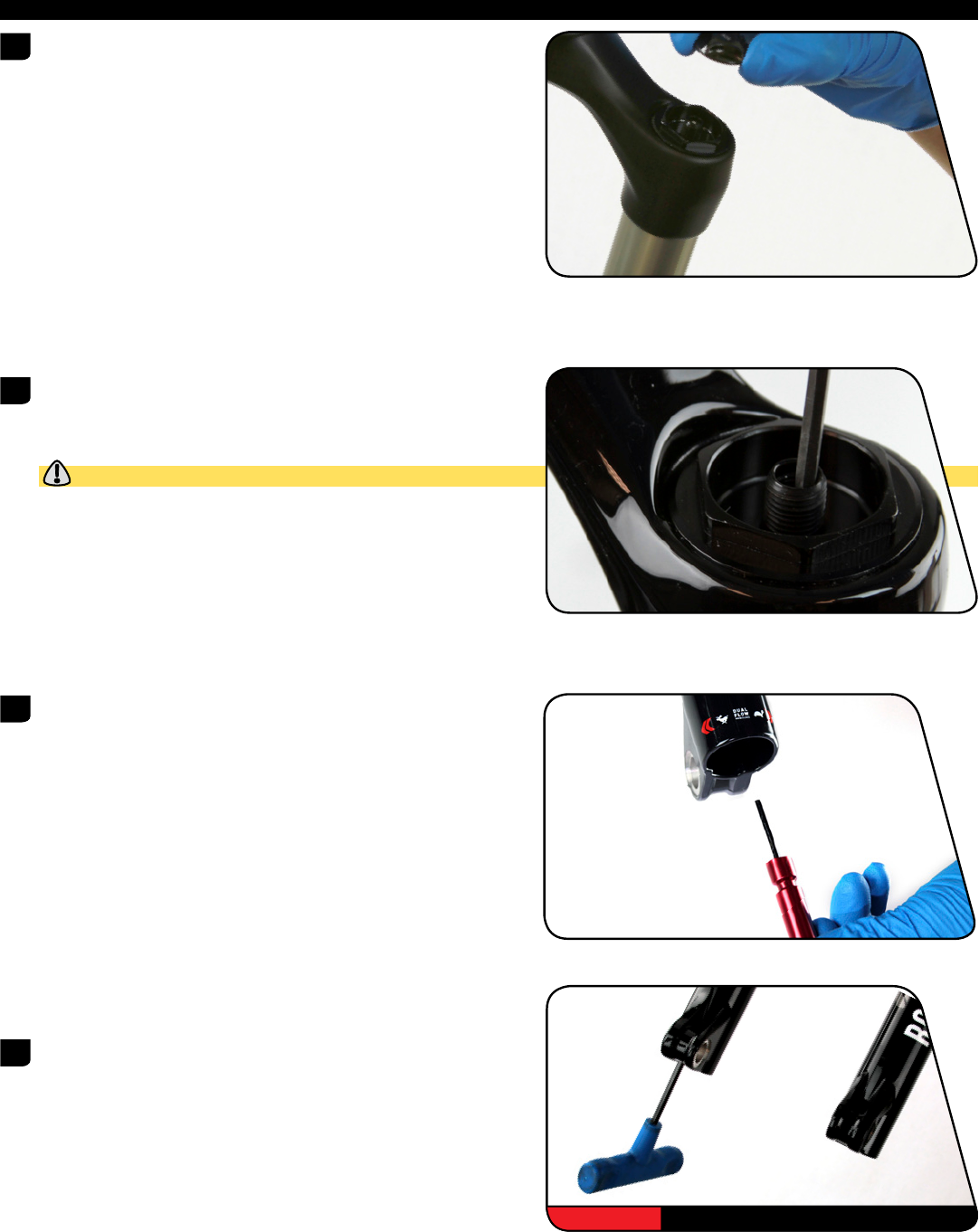
L o w e r L e g R e m o v a l 5 0 / 2 0 0 H o u r S e r v i c e L o w e r L e g R e m o v a l Remove the air valve cap.
-
Page 10: 50/200 Hour Service
Strike the wrench to dislodge the shaft from the lower leg on each side. 5 mm Remove each bottom bolt. Mallet & 5 mm Firmly pull the lower leg downward until oil begins to drain. Continue pulling downward to remove the lower leg. If the lower leg does not slide off of the upper tube or if oil does not drain from either side, the press fit of the shaft(s) into the lower leg may still be engaged.
-
Page 11: Lower Leg Service
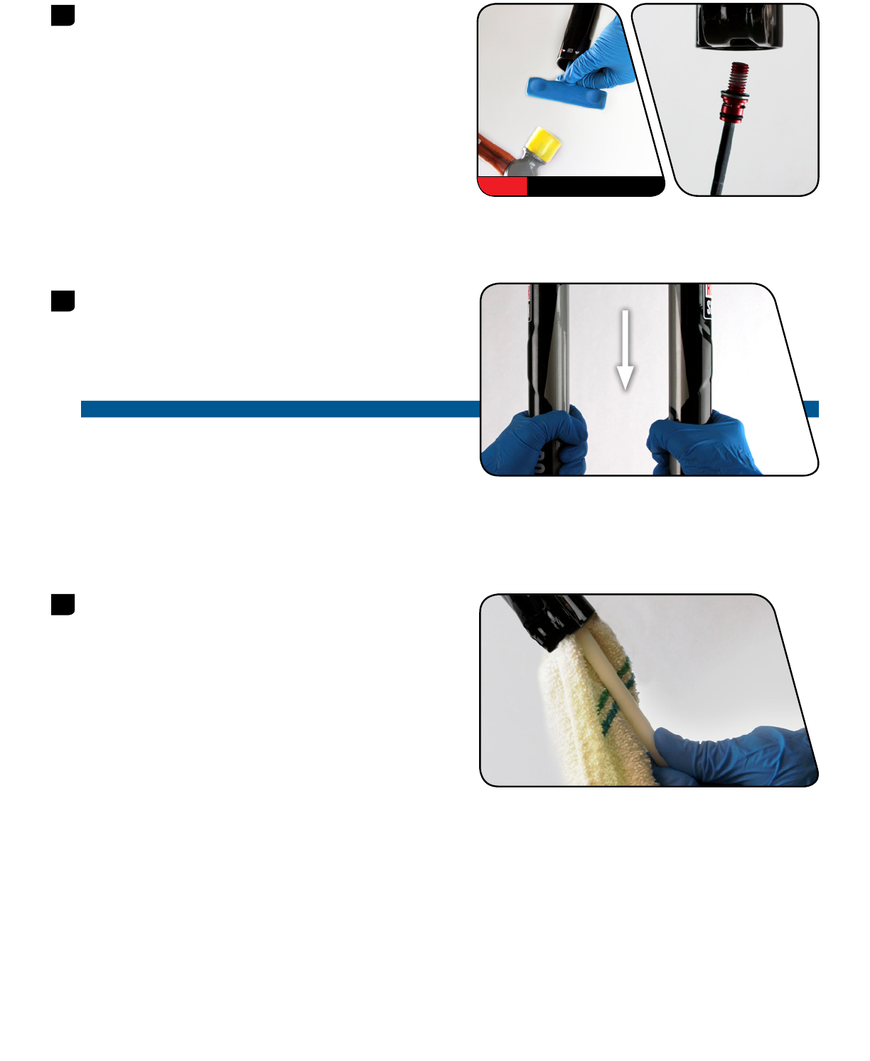
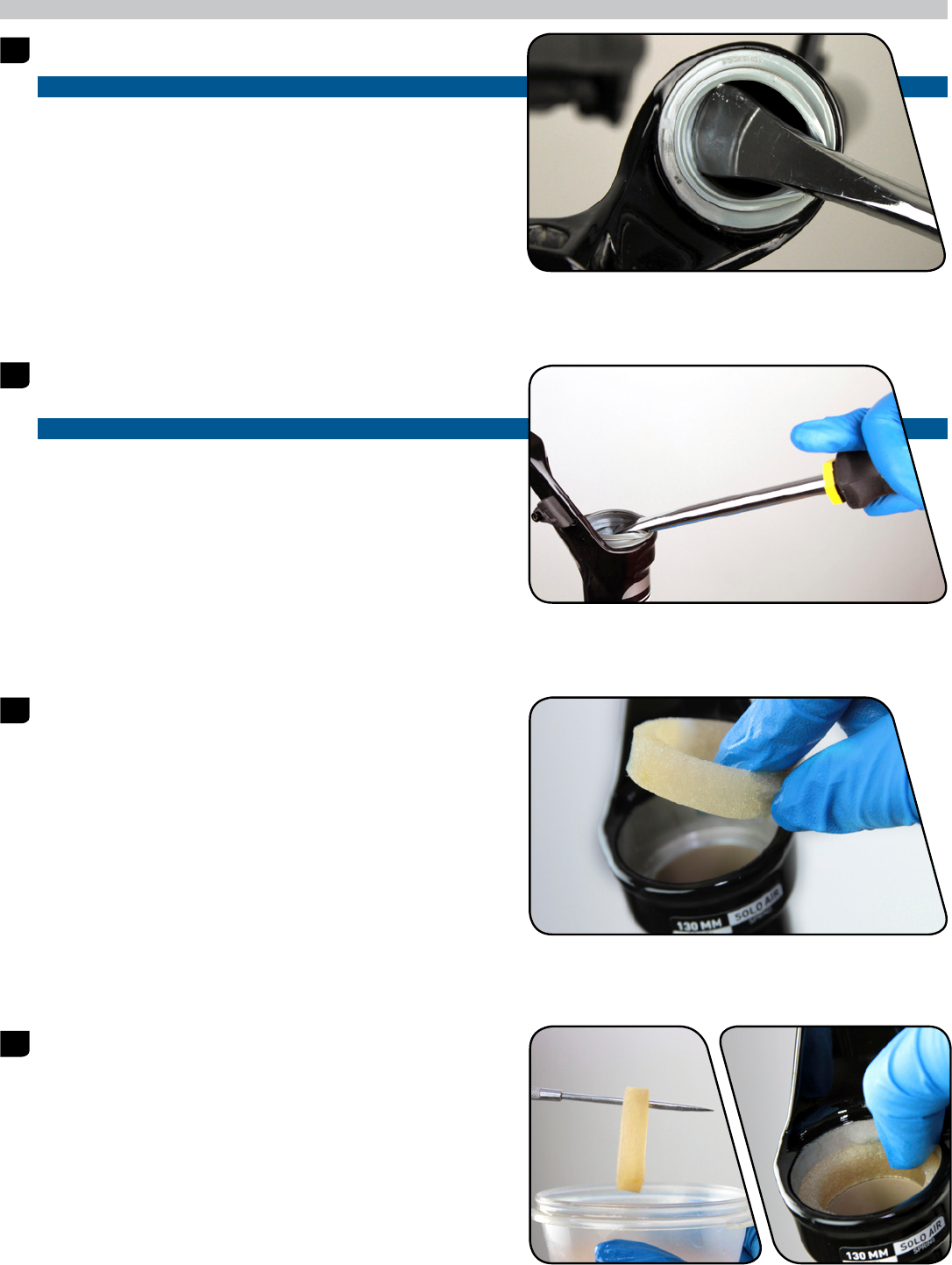
5 0 H o u r S e r v i c e L o w e r L e g S e r v i c e Remove the foam rings. Spray the foam rings with isopropyl alcohol and clean them with a rag.
-
Page 12: 200 Hour Service
2 0 0 H o u r S e r v i c e L o w e r L e g S e a l S e r v i c e Stabilize the lower leg on a bench top. Place the tip of a downhill tire lever under the wiper seal.
-
Page 13
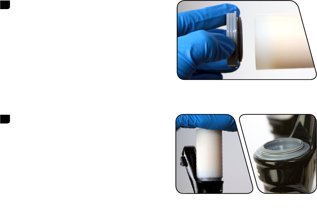
Remove the outer wire spring from each new wiper seal and set them aside. Insert the narrow end of a new wiper seal into the recessed end of the 32 mm Flanged appropriate RockShox® seal installation tool. 32 mm Flangeless Hold the lower leg steady and press the wiper seal into the lower leg until 32 mm Flanged… -
Page 14: Solo Air™ Spring Service
T r a v e l C h a n g e A d j u s t m e n t — O p t i o n a l To increase or decrease the travel in your Reba® or Bluto™ fork, the air spring must be replaced with the correct length air spring shaft assembly. Refer to the RockShox®…
-
Page 15: 200 Hour Service
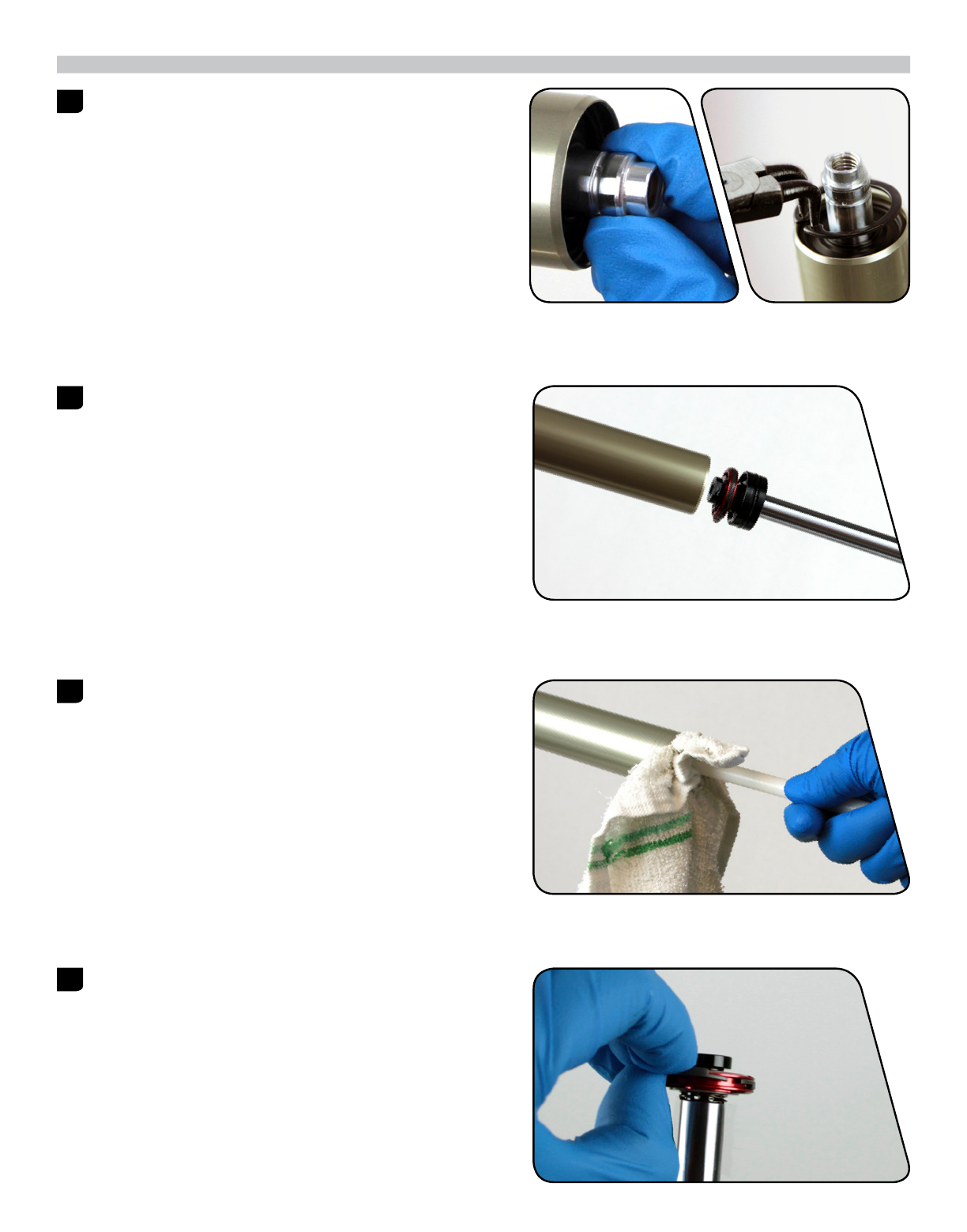
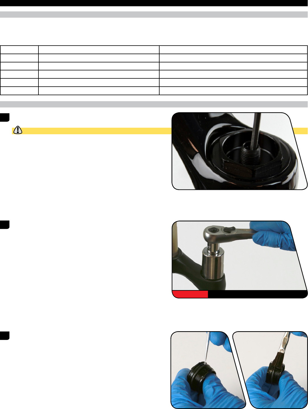
Reba only Only use SRAM® Butter grease on Bluto™ forks. Use Liquid O-Ring® PM600 military grease or SRAM Butter when servicing Reba® forks. No other grease is approved for use. When replacing seals and o-rings, use your fingers or a pick to remove the seal or o-ring.
-
Page 16
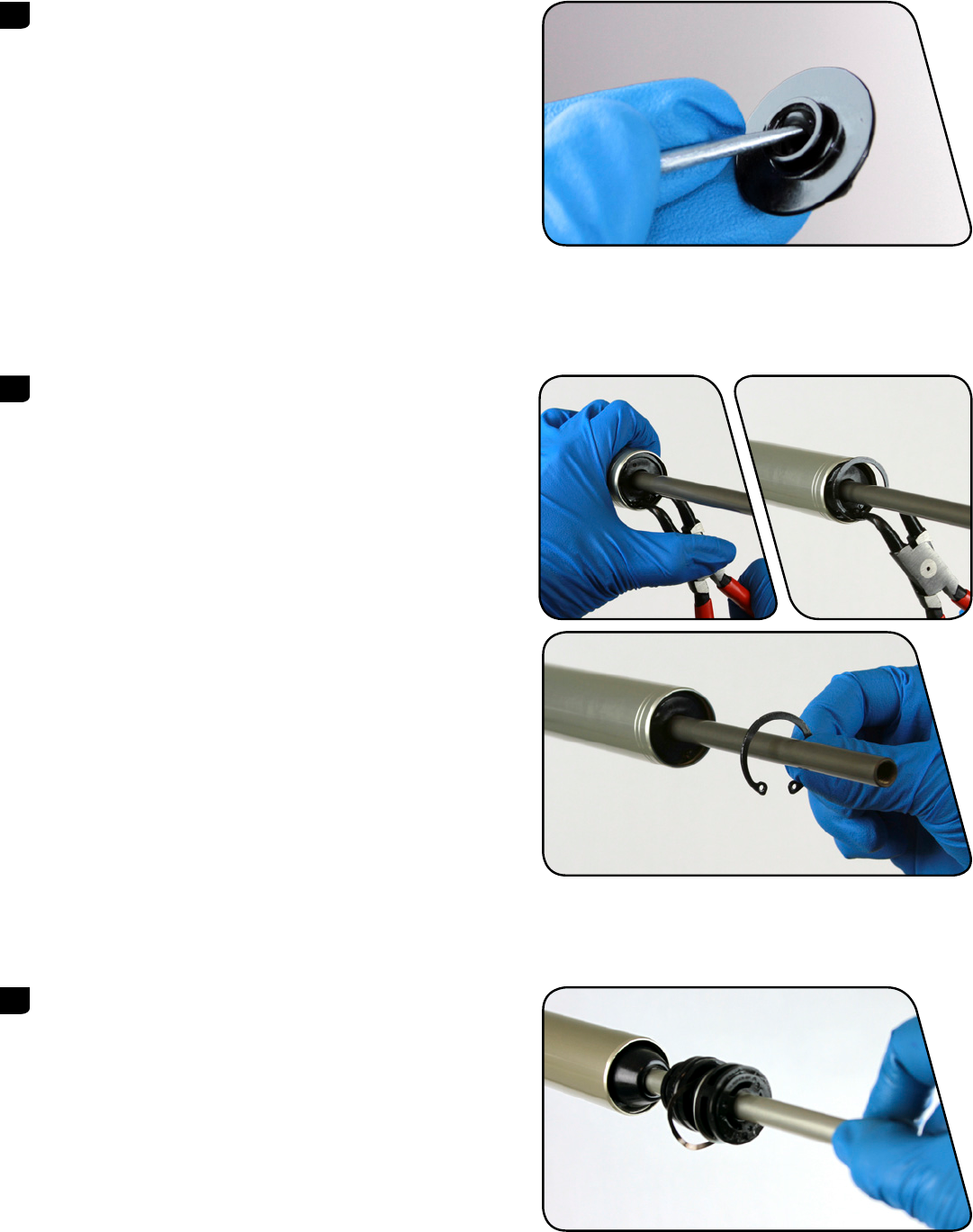
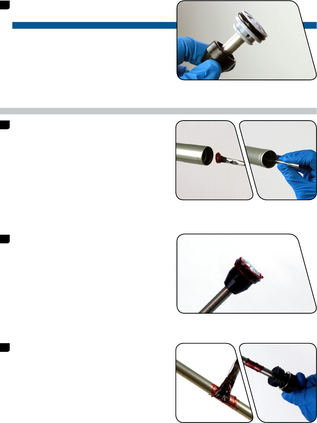
Reba® 100 mm travel forks: Remove the jounce bottom out bumper from the air shaft. Push the air shaft into the upper tube to prevent it from getting scratched Retaining ring pliers while removing the retaining ring. Use a flat blade screwdriver to push the air shaft guide under the retaining ring. -
Page 17
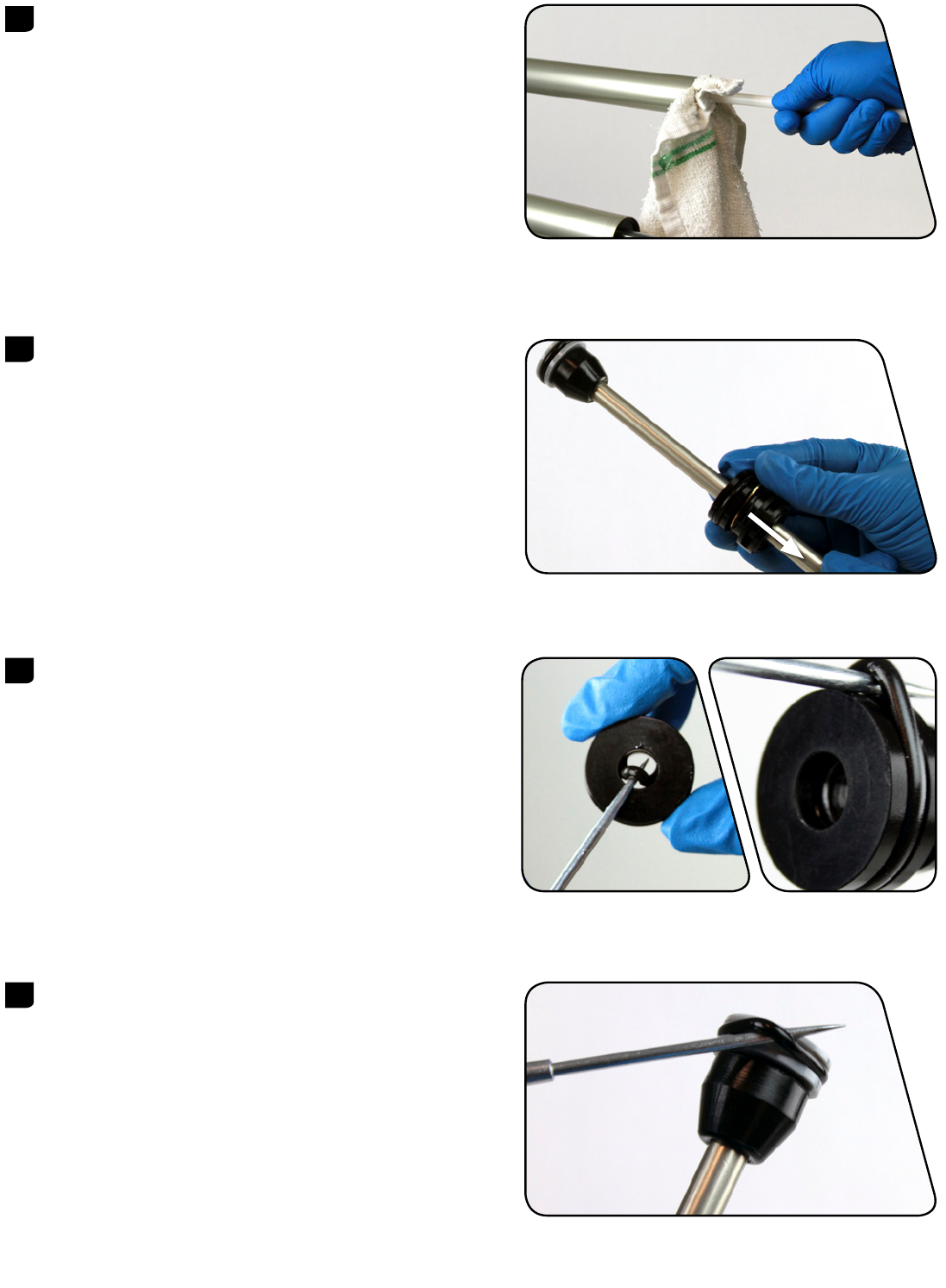
Clean the inside and outside of the upper tube. Inspect the inside and outside of the upper tube for damage. Remove the seal head assembly from the air shaft. Clean the air shaft assembly. Air Spring Service… -
Page 18
Pick Remove the air piston outer o-ring. Apply grease and install a new o-ring. SRAM Butter (Bluto™ or Reba®) / PM600 (Reba only) Remove the top out bumper cone from the air piston. Inspect the tension pin hole on the air piston. Install the top out bumper cone onto the air piston. -
Page 19
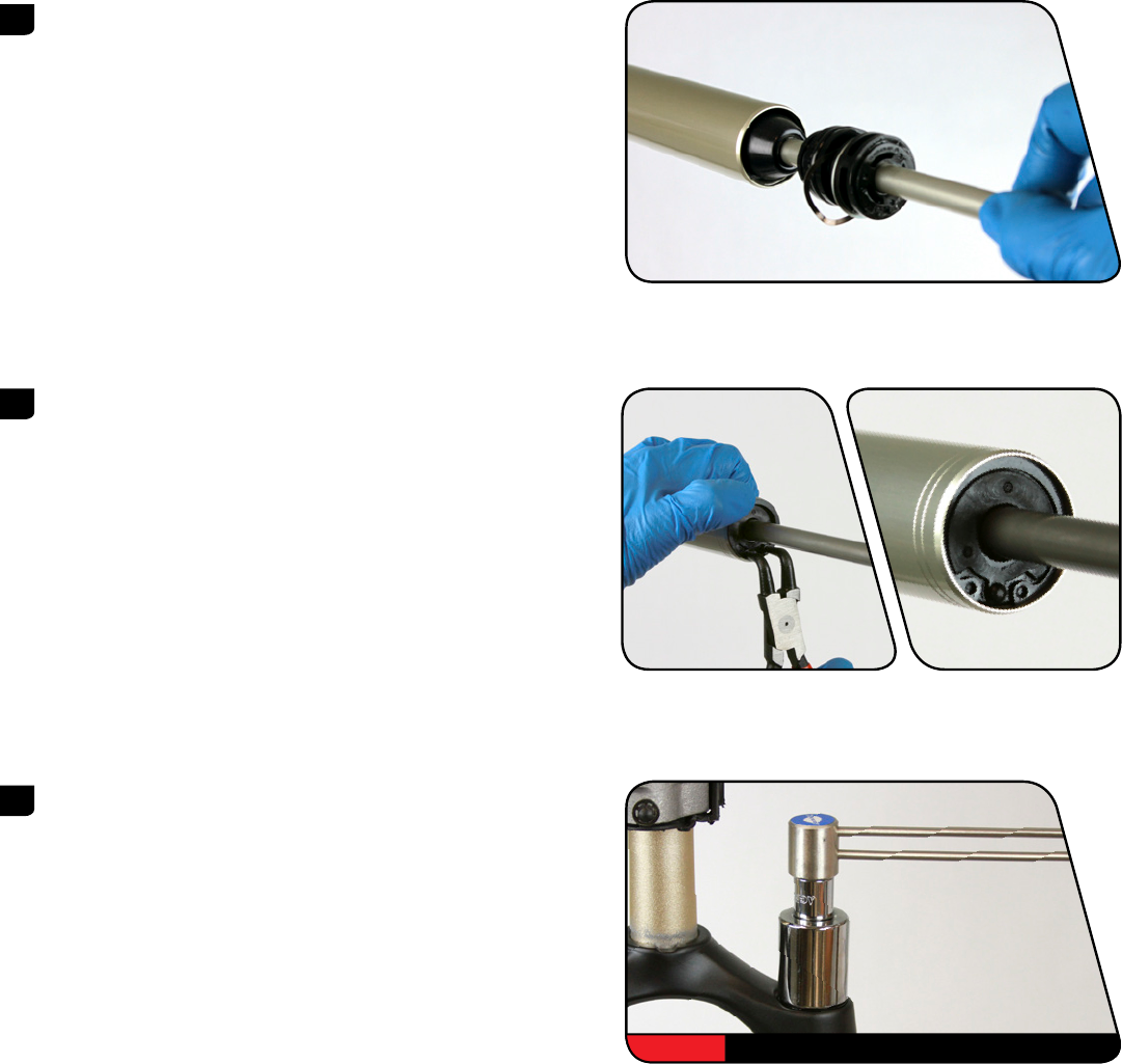
Apply a liberal amount of grease to the air piston and top out bumper cone. SRAM Butter (Bluto™ or Reba®) / PM600 (Reba only) Apply a liberal amount of grease 40-60 mm wide around the air shaft. Install the floating seal head, floating seal head top out bumper, aluminum support washer, wavy washer, and air shaft guide, in that order, onto the air shaft. -
Page 20
Reba® 100 mm travel forks: Install the jounce bottom out bumper on the air shaft. -
Page 21: Motion Control™ Dna Damper Service
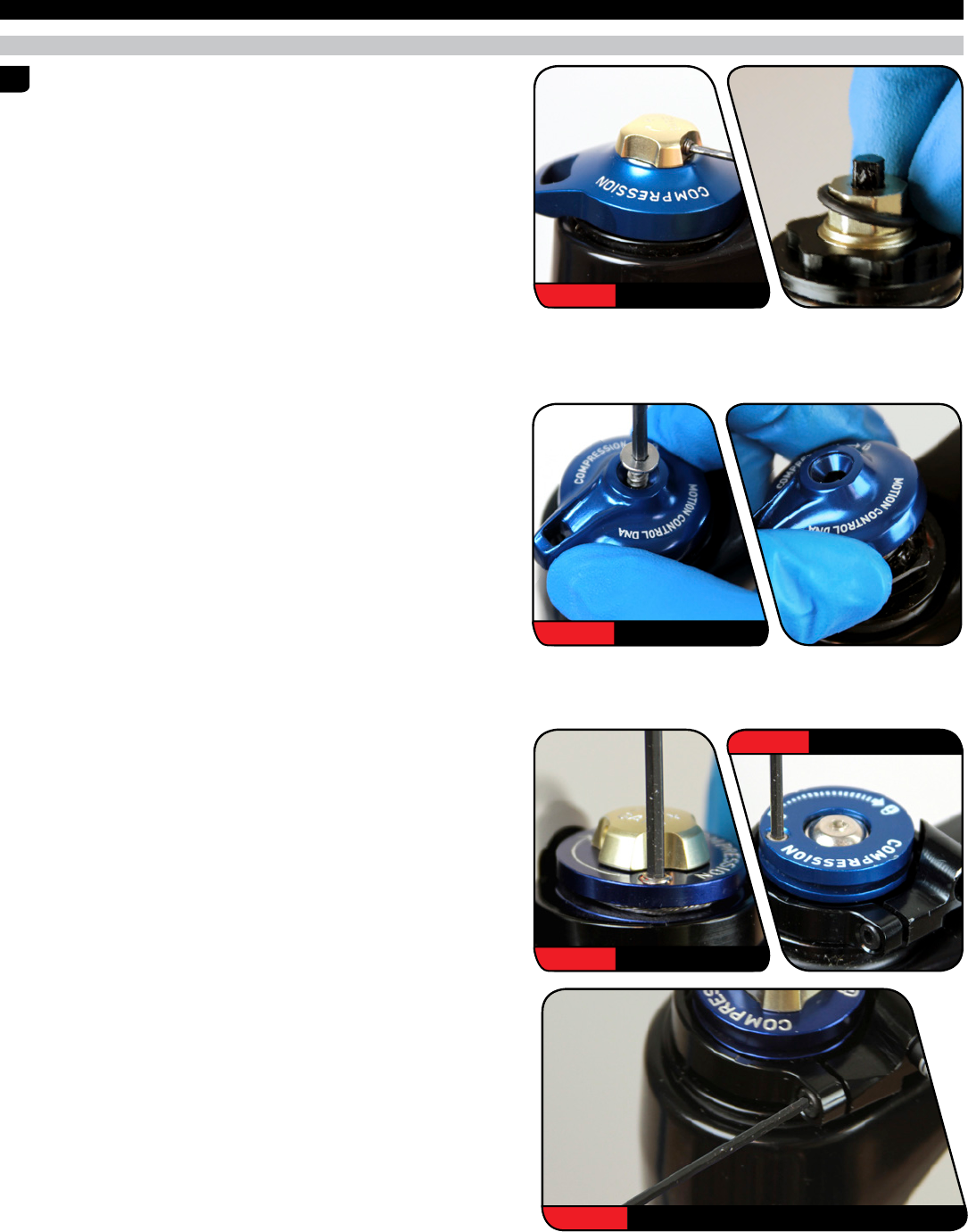
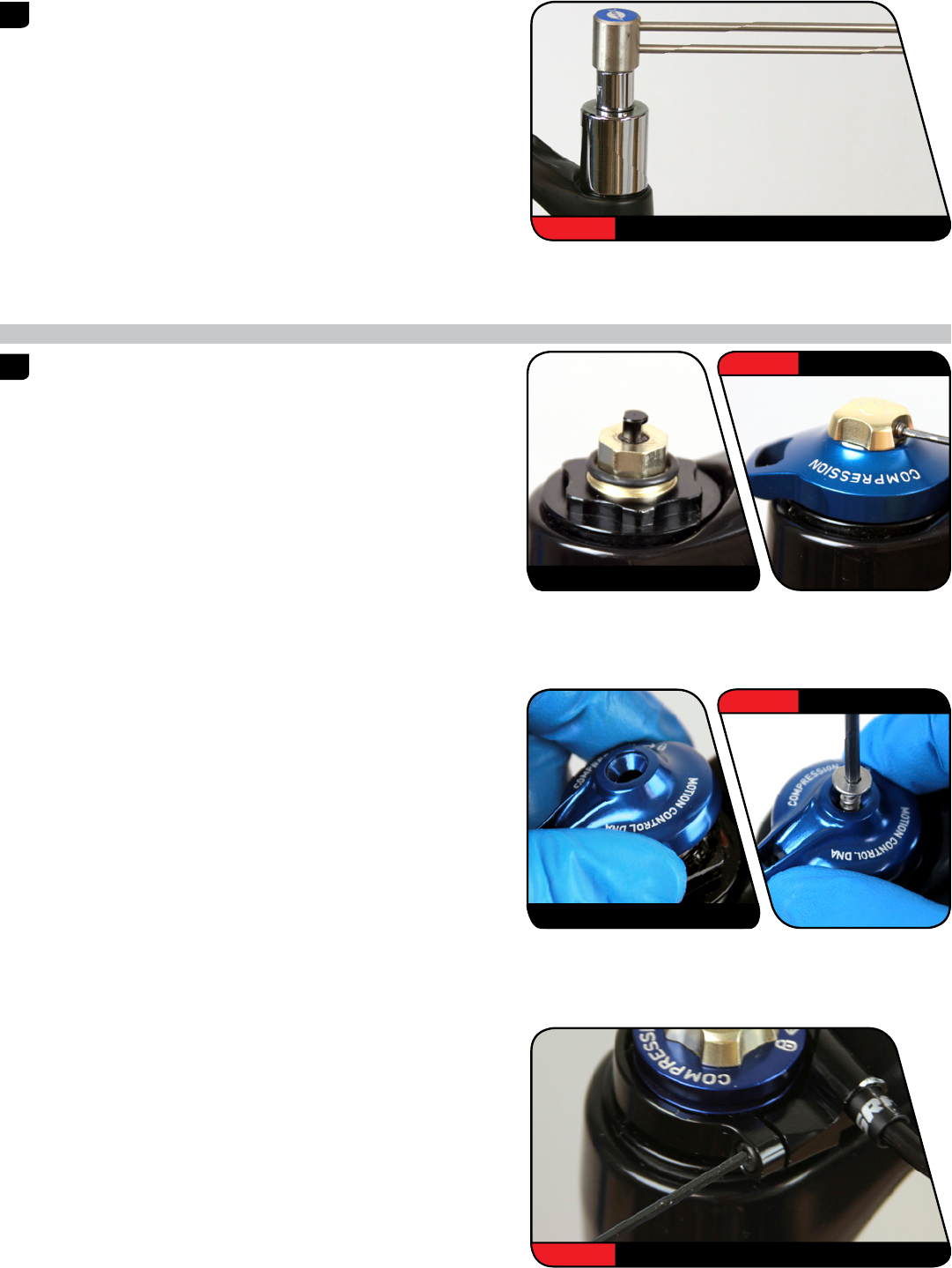
M o t i o n C o n t r o l ™ D N A D a m p e r S e r v i c e 2 0 0 H o u r S e r v i c e D a m p e r S e r v i c e Crown Adjust: Rotate the adjuster knob to the open position.
-
Page 22
Remove the compression top cap o-ring. Install a new o-ring. Grease or 5wt Remove the compression damper piston o-ring. Apply grease to the new RL Remote o-ring and install it. RCT3: Install a new glide ring on the compression damper piston. RCT3 RCT3 Pour the suspension oil into an oil pan. -
Page 23
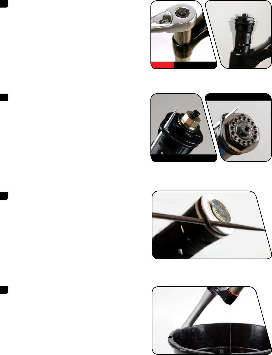
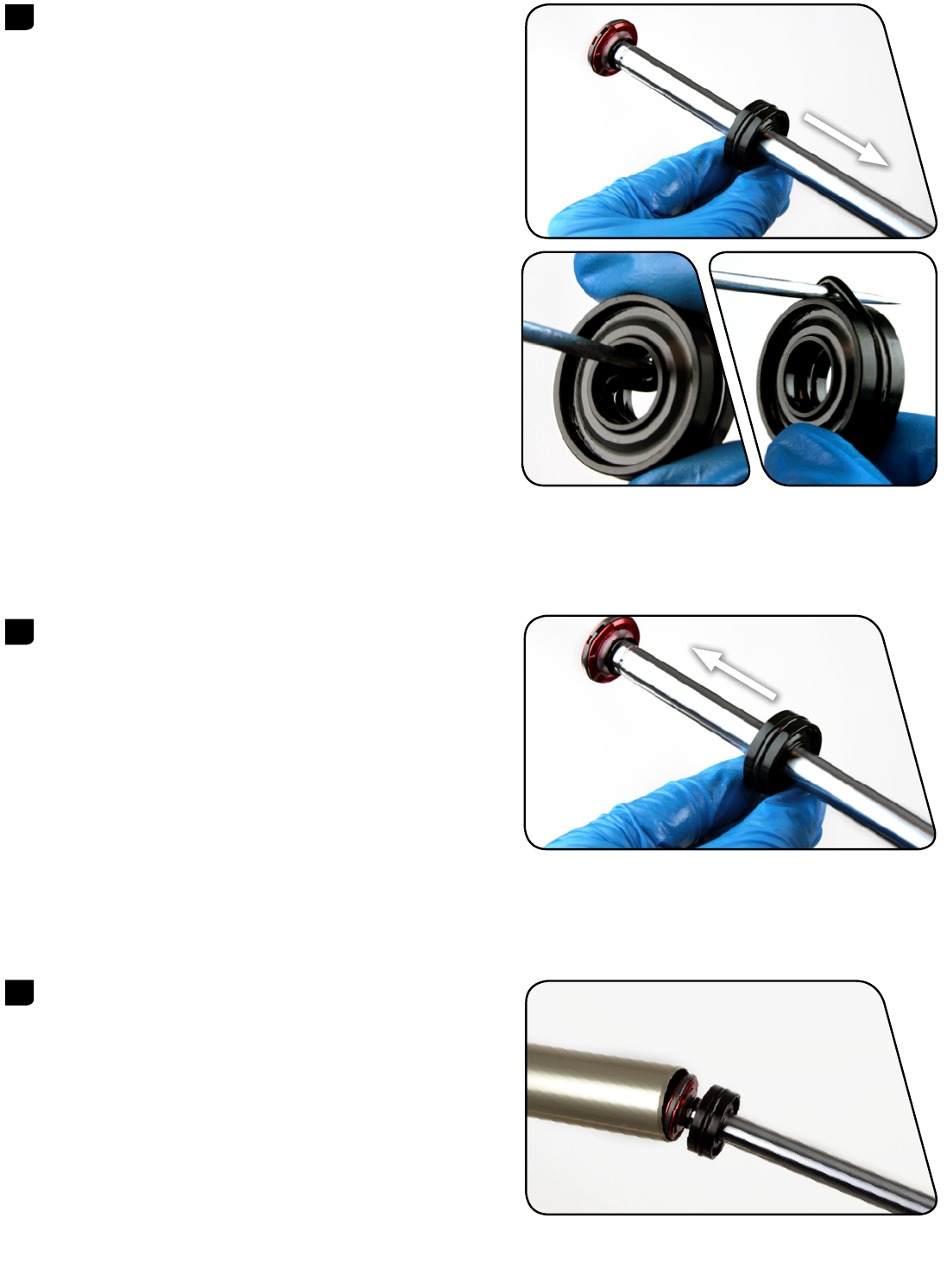
Push the rebound damper shaft into the upper tube and remove the Retaining ring pliers rebound damper retaining ring. NOT ICE Do not let the retaining ring contact the shaft. Scratches on the shaft will allow fluid to bypass the seal head into the lower leg. Scratches can result in reduced damper performance. -
Page 24
Remove the outer seal head o-ring. Use a pick to pierce and remove the inner seal head o-ring. Apply grease to the new o-rings and install them on the seal head. Remove the glide ring from the piston and install a new glide ring. Install the seal head on the damper shaft. -
Page 25
Pull the rebound damper shaft out to the fully extended position. Pour suspension oil into the damper side upper tube. Travel Oil Volume Oil Height Fork Model (mm) +/- 2 (mL) (mm) RCT3 Bluto™ 80-120 80-100 70-75 Reba® 110-120 130-150 Damper Service… -
Page 26
RL and RCT3: Verify the compression damper valve is in the open position. A closed compression valve will restrict oil flow during installation. Install the compression damper into the upper tube. Press down and rotate in a circular motion until the damper is installed. Tighten the top cap. -
Page 27
RCT3: Install the compression adjuster knob on the top cap so the knob 1.5 mm 0.6 N·m (5 in-lb) rotates from open to closed. Install and tighten the washer bolt. Install and tighten the low speed compression knob and set screw. 10 mm RCT3 RL: Install the lockout adjuster knob on the top cap so the knob rotates from… -
Page 28: Lower Leg Assembly
L o w e r L e g A s s e m b l y 5 0 / 2 0 0 H o u r S e r v i c e L o w e r L e g I n s t a l l a t i o n Clean the upper tubes.
-
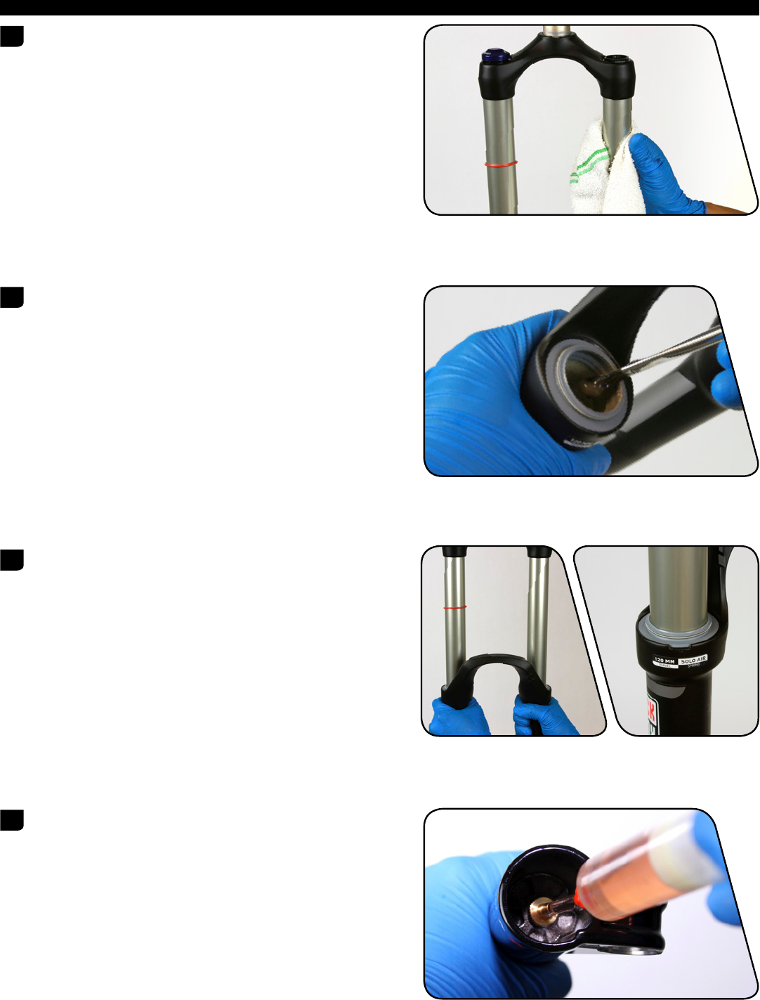
Page 29
Position the fork at an angle with the lower leg bolt holes oriented upward. Angle a syringe fitting in each lower leg bolt hole so the oil will only contact the inside of the lower leg. Inject 5 mL of suspension oil into each lower leg through the lower leg bolt hole. -
Page 30
Install the air valve cap onto the air spring top cap. Clean the entire fork. This concludes the service of your RockShox® Bluto™ & Reba® suspension forks. For Remote user manuals, please visit www.sram.com/service. Lower Leg Installation… -
Page 31
This publication includes trademarks and registered trademarks of the following company: Liquid-O-Ring® is a registered trade name of Oil Center Research, Inc. -
Page 32
www.sram.com ASIAN HEADQUARTERS WORLD HEADQUARTERS EUROPEAN HEADQUARTERS SRAM Taiwan SRAM LLC SRAM Europe No. 1598-8 Chung Shan Road 1000 W. Fulton Market, 4th Floor Paasbosweg 14-16 Shen Kang Hsiang, Taichung City Chicago, Illinois 60607 3862ZS Nijkerk Taiwan R.O.C. The Netherlands…
This manual is also suitable for:
Bluto
Download Service manual of Rock Shox Bluto Bicycle Accessories for Free or View it Online on All-Guides.com.

1

2

3

4

5

6

7

8

9

10

11

12

13

14

15

16

17

18

19

20

21

22

23

24

25

26

27

28

29

30

31

32

GEN0000000005114 Rev C
© 2017 SRAM, LLC
2017-2018
REBA® and Bluto™
service
manual
Specifications:
|
Accompanying Data:
Rock Shox REBA Bicycle Accessories PDF Service Manual (Updated: Wednesday 15th of February 2023 12:33:10 AM)
Rating: 4.6 (rated by 33 users)
Compatible devices: reverb a2, oneloc remote, Judy T2, Seatpost 2002, BoXXer R2C2, PILOT, 30, SID RACE ADJUST.
Recommended Documentation:
Rock Shox REBA: Text of Service Manual
(Ocr-Read Version Summary of Contents, UPD: 15 February 2023)
-
15, 16Air Spring Service 200 Hour Service Air Spring Service ⚠ WARNING- EYE HAZARD Verify all pressure is removed from the fork before proceeding. Depress the Schrader valve again to remove any remaining air pressure. Failure to do so can result in injury and/or damage to the fork. NOTICE Only use SRAM® Butter grease on Bluto™ forks. Use Liquid O-Ring® PM600 military grease or SRAM Butter when…
-
17, 18Air Spring Service Clean the inside and outside of the upper tube. Inspect the inside and outside of the upper tube for damage. Remove the seal head assembly from the air shaft. Clean the air shaft assembly. 6 space between frames space between steps 7
… -
14, 15Solo Air™ Spring Service Solo Air™ Spring Service Travel Change Adjustment — Optional To increase or decrease the travel in your Reba® or Bluto™ fork, the air spring must be replaced with the correct length air spring shaft assembly. Refer to the RockShox® Spare Parts Catalog available on our website at www.sram.com/service for spare part kit details. Solo Air™ Bottomless …
-
3, TABLE OF CONTENTS EXPLODED VIEW ………………………………………………………………………………………………………………………………………………………………………………………………………………………. 6 ROCKSHOX® SERVICE …………………………………………………………………….…
-
31, This publication includes trademarks and registered trademarks of the following company: Liquid-O-Ring® is a registered trade name of Oil Center Research, Inc.
… -
32, 33 ASIAN HEADQUARTERS SRAM Taiwan No. 1598-8 Chung Shan Road Shen Kang Hsiang, Taichung City Taiwan R.O.C. WORLD HEADQUARTERS SRAM LLC 1000 W. Fulton Market, 4th Floor Chicago, Illinois 60607 USA EUROPEAN HEADQUARTERS SRAM Europe Paasbosweg 14-16 3862ZS Nijkerk The Netherlands www.sram.com
… -
25, 26Damper Service Push the rebound seal head into the upper tube until the retaining ring groove is visible. Retaining rings have a sharper-edged side and a rounder-edged side. Install retaining rings with the sharper-edged side facing the tool to allow for easier installation and removal. Push the rebound damper shaft into the upper tube to prevent it from getting scratched while installing …
-
18, 19Air Spring Service Remove the outer and inner o-rings on the floating seal head. Apply grease and install new o-rings. Remove the air piston outer o-ring. Apply grease and install a new o-ring. Remove the top out bumper cone from the air piston. Inspect the tension pin hole on the air piston. Install the top out bumper cone onto the air piston. NOTICE If the tension pin is protruding…
-
13, 14Lower Leg Seal Service Remove the outer wire spring from each new wiper seal and set them aside. Insert the narrow end of a new wiper seal into the recessed end of the appropriate RockShox® seal installation tool. Hold the lower leg steady and press the wiper seal into the lower leg until the seal surface is flush with the top of the lower leg. Repeat on t…
-
12, 13Lower Leg Seal Service 200 Hour Service Lower Leg Seal Service Stabilize the lower leg on a bench top. Place the tip of a downhill tire lever under the wiper seal. Press down on the downhill tire lever handle to remove the seal. Repeat on the other side. Discard the wiper seals. NOTICE Keep the lower leg stable. Do not allow the lower leg to twist in opposit…
-
8, 9Recommended Service Intervals Recommended Service Intervals Regular service is required to keep your RockShox® product working at peak performance. Follow this maintenance schedule and install the service parts included in each service kit that corresponds with the Service Hours Interval recommendation below. For spare part kit contents and details, refer to the …
-
30, 31Lower Leg Installation Install the rebound damper knob. Refer to your pre-service recorded rebound setting to adjust the rebound. Refer to your pre-service recorded settings to pressurize your air spring, or use the air chart on the fork’s lower leg and pressurize the air spring. You may see a drop in the indicated air pressure on the pump gauge while fillin…
-
22, 23Damper Service Remove the compression top cap o-ring. Install a new o-ring. Remove the compression damper piston o-ring. Apply grease to the new o-ring and install it. RCT3: Install a new glide ring on the compression damper piston. Pour the suspension oil into an oil pan. 3 Grease or 5wt 4 RL RL Remote RCT3 RCT3 5
… -
2, SRAM® LLC WARRANTY EXTENT OF LIMITED WARRANTY Except as otherwise set forth herein, SRAM warrants its products to be free from defects in materials or workmanship for a period of two years after original purchase. This warranty only applies to the original owner and is not transferable. Claims under this warranty must be made through the retailer where the bicycle or the SRAM component was p…
-
11, 12Lower Leg Service 50 Hour Service Lower Leg Service Remove the foam rings. Spray the foam rings with isopropyl alcohol and clean them with a rag. Soak the foam rings in suspension oil. Clean the inside and outside of the lower leg. Clean the wiper seals. Install the foam rings under the wiper seals. 50 Hour Service Continue the 50 Hour Service wi…
Rock Shox REBA: Recommended Instructions
L206WTQ-BF — — 20″ LCD Monitor, GT1531, 67 20 03, TFC-461R


-
TÜV Rheinlandgeprüfte Sicherheit608•3DF2/501-6216-05Follow me…Box 69, 330 33 Hillerstorp, SWEDENwww.thule.com2973-24973240SKNávod na montážSLONavodila za pritrjevanjeHRUputa za sastavljanjeHUA felszerelés módjaGRΟδηγες συναρμολγησηςTRMontaj talimatlar¤Óá¹Ð¹Ó¡ÒõԴµÑé§GB Fitting instructionsD MontageanleitungF I …
973-24 2
-
Lifevisa WIRELESS BIKE CADENCE SENSOR [RPS-2300] USER MANUALCOMPONENTSCADENCE SENSOR BATTERY INSTALLMENTThis Cadence Sensor includes a 3V CR2032 lithium battery. Please follow below steps to install the battery.Step 1. Insert the battery (CR2032) with the positive (+) side up.Make sure the battery is hooked by the contact spring.Step 2.Put on the O-Ring in the groove to ensure water …
RPS-2300 2
-
1 23 546 7B-TRAVELbellelli srlvia meucci 232 — 45021 badia polesineRovigo — ITALYwww.bellelli.comproduced by:MAX3 kg / 6.5 lbsMAX35 kg / 77 lbsMAX16 kg / 35 lbsMAX1,10 m / 43”MAX 2 CHILDREN>9 monthsMAX3 kg / 6.5 lbsMAX35 kg / 77 lbsMAX16 kg / 35 lbsMAX1,10 m / 43”MAX 2 CHILDREN>9 monthsMAX3 kg / 6.5 lbsMAX35 kg / 77 lbsMAX16 kg / 35 lbsMAX1,10 m / 43”MAX 2 CHILDREN>9 month …
B-TRAVEL 26
-
StageStage 1: Increase Pedal EfficiencyStage 2: Better Muscle BalanceStage 3:Full ActivationStage 4:Customization and Finalization Cause SymptomSolutionROTOR Q-Ring Setup GuidePart 2: CUSTOMIZING Q-RING SETUPIt is recommended you complete part 1 (minimum 10 hours riding) before changing your OCP (Optimum Chainring Position) setupRoad or XC2 bike? Start in position 3Triathl …
Q-Ring 2
-
CHARGINGLIGHT OPERATION & BATTERY LIFEUSER GUIDEBLAZEFully Charge your light before rst use. Locate the charge port on top of the light by lifting the silicone top cap.IMPORTANT: After charging is complete correctly replace the top-cap to prevent water ingress.Fully insert the USB Top-Up Cable and begin charging from a USB supply. An LED behind the Function Button will ash green to ind …
BLAZE 4
-
1191116C-Bow Taschenhalter / Soft bag holderTRIUMPH Thruxton/Rab Baujahr 2016 / from date of manufacture 2016Artikel Nr.: / Item-no.: 6630 7542 00 01 schwarz/black 630 7542 00 02 chrom/chrome1x 700009474 Halter vorne links schwarz — adapter front left black1 700009478 Schraubensatz/Screw kit:1x 700009475 Halter vorne rechts schwarz — adapter front right black2x U-Sc …
C-Bow 4
-
2x Zylinderschraube Innensechskant M8x402x Zylinderschraube Innensechskant M8x554x Zylinderschraube Innensechskant M6x204x Zylinderschraube Innensechskant M6x124x Selbstsichernde Mutter M64x Viereck-Scheibe 20x20x ø6,46x U- Scheibe Ø6,42x U- Scheibe Ø8,42x Aludistanz Ø18xØ9x40mm2x allen screw M8x402x allen screw M8x554x allen screw M6x204x allen screw M6x1 …
Easyrack 4
-
UserManualHAMAX OUTBACK / OUTBACK ONEMultifunctional child carrier2-in-1 Bicycle trailercdeafbdce123lmbagclick!click!4 576baaHamax ASVålerveien 159N-1599 MossNorwayTel.: +47 69 23 38 38email: [email protected] User Manual Outback 2-in-1 ASTM Only10846 Rev. 009kbaihfabjCONTENTSEN — English 9FR — Français 14ES — Español 20Strollergh10846, Rev. 008, Manu …
OUTBACK 23
-
Charging � …
Zecto Drive 2
Additional Information:
Product Types by Rock Shox:
- Bicycle Accessories
- Bicycle
Popular Right Now:
Operating Impressions, Questions and Answers:

FORK SPRING WHEEL
SIZE MODEL <140 LBS
(<63 KG)
140-160
LBS
(63-72 KG)
160-180
LBS
(72-81 KG)
180-200
LBS
(81-90 KG)
200-220
LBS
(90-99 KG)
MAX PSI
Argyle Solo Air 26” RCT 120-135 psi 135-150 psi 150-165 psi 165-180 psi 180+ psi 220 psi
BoXXer Solo Air 26” World Cup 40-55 psi 55-70 psi 70-85 psi 85-100 psi 100-115 psi 200 psi
Lyrik
Dual
Position
Air
26” RC2L, RC2 DH,
RC, R 45-65 psi 65-85 psi 85-105 psi 105-125 psi 125-145 psi 248 psi
Solo Air 26” RC2L, RC2 DH,
RC, R 45-55 psi 55-65 psi 65-75 psi 75-85 psi 85-95 psi 148 psi
Reba Dual Air 29” RLT, RL, RLT, RL 70-90 psi 90-105 psi 105-120 psi 120-135 psi 135+ psi 200 psi
Recon Gold
80mm Solo Air
26” RL, TK, R
90-110 psi 110-125 psi 125-140 psi 140-160
psi 175+ psi 225 psi
29” TK
Recon Gold
100-120mm Solo Air
26” RL, TK, R
50-70 psi 70-85 psi 85-100 psi 100-120 psi 135+ psi 225 psi
29” TK
Recon
Silver
80mm
Solo Air
26” TK, R
90-110 psi 110-125 psi 125-140 psi 140-160 psi 175+ psi 225 psi
29” TK
Recon
Silver
100-120mm
Solo Air
26” TK, R
50-70 psi 70-85 psi 85-100 psi 100-120 psi 135+ psi 225 psi
29” TK
Revelation
Dual Air
26” World Cup, XX,
RCT3, RLT, RL, 70-90 psi 90-105 psi 105-120 psi 120-135 psi 135+ psi 200 psi
29” XX, RCT3, RLT, RL
Dual
Position
Air
26”
World Cup, World
Cup XX, XX, RCT3,
RLT, RL <110 psi 110-125 psi 125-140 psi 140-155 psi 155-170 psi 250 psi
29” XX, RCT3, RLT, RL
Sektor Solo Air 26” RL, TK 50-70 psi 70-85 psi 85-100 psi 100-115 psi 115-130+
psi 225 psi
SID Dual Air
26”
World Cup XX,
World Cup, XX,
RTC3, RLT, RL
70-90 psi 90-105 psi 105-120 psi 120-135 psi 135+ psi 200 psi
29”
World Cup XX,
World Cup, XX
29, RCT3, RLT, RL
Totem
Dual
Position
Air
26” RC, RC2 DH 35-40 psi 40-55 psi 55-75 psi 75-90 psi 90-110 psi 186 psi
Solo Air 26” RC2 DH 20-35 psi 35-50 psi 50-65 psi 65-80 psi 80-95 psi 148 psi
SUSPENSION FORK
Air Spring Chart
2012
GEN.0000000004148)Rev)A

2013
Reba Service Manual
GEN.0000000004216 Rev A © 2012 SRAM LLC

SRAM LLC WARRANTY
EXTENT OF LIMITED WARRANTY
!»#$%&'()’*&+$,-.)$’)$&’/*,&+’+$,$.01’2345′-(,,(0&)’.&)’%,*67#&)’&*’8$’/,$$’/,*9’6$/$#&)’.0’9(&$,.(:)’*,’-*,;9(0)+.%’/*,'(‘%$,.*6’*/’&-*'<$(,)'(/&$,’
*,.=.0(:’%7,#+()$>‘‘?+.)’-(,,(0&<‘*0:<‘(%%:.$)’&*’&+$’*,.=.0(:’*-0$,'(06′.)’0*&’&,(0)/$,(8:$>’@:(.9)’706$,’&+.)’-(,,(0&<’97)&’8$’9(6$’&+,*7=+’&+$’,$&(.:$,’
-+$,$’&+$’8.#<#:$’*,’&+$’2345’#*9%*0$0&’-()’%7,#+()$6>’A,.=.0(:’%,**/’*/’%7,#+()$’.)’,$B7.,$6>’Except’as’described’herein,’SRAM’makes’no’
other’warranties,’guaranties,’or’representations’of’any’type'(express’or’implied),’and’all’warranties'(including’any’implied’warranties’of’
reasonable’care,’merchantibility,’or’fitness’for’a’particular’purpose)’are’hereby’disclaimed.
LOCAL LAW
7KLVZDUUDQWVWDWHPHQWJLYHVWKHFXVWRPHUVSHFL¿FOHJDOULJKWV7KHFXVWRPHUPDDOVRKDYHRWKHUULJKWVZKLFKYDUIURPVWDWHWRVWDWH86$IURP
SURYLQFHWRSURYLQFH&DQDGDDQGIURPFRXQWUWRFRXQWUHOVHZKHUHLQWKHZRUOG
7RWKHH[WHQWWKDWWKLVZDUUDQWVWDWHPHQWLVLQFRQVLVWHQWZLWKWKHORFDOODZWKLVZDUUDQWVKDOOEHGHHPHGPRGL¿HGWREHFRQVLVWHQWZLWKVXFKODZXQGHU
VXFKORFDOODZFHUWDLQGLVFODLPHUVDQGOLPLWDWLRQVRIWKLVZDUUDQWVWDWHPHQWPDDSSOWRWKHFXVWRPHU)RUH[DPSOHVRPHVWDWHVLQWKH8QLWHG6WDWHV
RI$PHULFDDVZHOODVVRPHJRYHUQPHQWVRXWVLGHRIWKH8QLWHG6WDWHVLQFOXGLQJSURYLQFHVLQ&DQDGDPD
(>’C,$#:76$’&+$’6.)#:(.9$,)'(06′:.9.&(&.*0)’*/’&+.)’-(,,(0&<‘)&(&$9$0&’/,*9′:.9.&.0=’&+$’)&(&7&*,<‘,.=+&)’*/’&+$’#*0)79$,»
HJ8QLWHG.LQJGRP
8>’A&+$,-.)$’,$)&,.#&’&+$'(8.:.&<‘*/'(‘9(07/(#&7,$,’&*’$0/*,#$’)7#+’6.)#:(.9$,)’*,’:.9.&(&.*0)>
For’Australian’customers:
7KLV65$0OLPLWHGZDUUDQWLVSURYLGHGLQ$XVWUDOLDE65$0//&1RUWK.LQJVEXUWKÀRRU&KLFDJR,OOLQRLV86$7RPDNHDZDUUDQW
FODLPSOHDVHFRQWDFWWKHUHWDLOHUIURPZKRPRXSXUFKDVHGWKLV65$0SURGXFW$OWHUQDWLYHORXPDPDNHDFODLPEFRQWDFWLQJ65$0$XVWUDOLD
5(,#*’@*7,&1’3*-D.::$’EFGH1′47)&,(:.(>’I*,’D(:.6’#:(.9)’2345′-.::1′(&’.&)’*%&.*01’$.&+$,’,$%(.,’*,’,$%:(#$'<*7,’2345’%,*67#&>»40<‘$»%$0)$)’.0#7,,$6′.0′
PDNLQJWKHZDUUDQWFODLPDUHRXUUHVSRQVLELOLW7KHEHQH¿WVJLYHQEWKLVZDUUDQWDUHDGGLWLRQDOWRRWKHUULJKWVDQGUHPHGLHVWKDWRXPDKDYH
706$,’:(-)’,$:(&.0=’&*’*7,’%,*67#&)>»A7,’=**6)’#*9$’-.&+’=7(,(0&$$)’&+(&’#(00*&’8$’$»#:76$6’706$,’&+$’47)&,(:.(0’@*0)79$,’J(->»K*7′(,$’$0&.&:$6’&*’
(‘,$%:(#$9$0&’*,’,$/706’/*,'(‘9(L*,’/(.:7,$'(06’/*,’#*9%$0)(&.*0’/*,'(0<‘*&+$,’,$()*0(8:<‘/*,$)$$(8:$’:*))’*,’6(9(=$>»K*7′(,$'(:)*’$0&.&:$6’&*’+(D$’&+$’
=**6)’,$%(.,$6’*,’,$%:(#$6′./’&+$’=**6)’/(.:’&*’8$’*/'(##$%&(8:$’B7(:.&<‘(06’&+$’/(.:7,$’6*$)’0*&'(9*70&’&*'(‘9(L*,’/(.:7,$>
LIMITATIONS OF LIABILITY
7RWKHH[WHQWDOORZHGEORFDOODZH[FHSWIRUWKHREOLJDWLRQVVSHFL¿FDOOVHWIRUWKLQWKLVZDUUDQWVWDWHPHQWLQQRHYHQWVKDOO65$0RULWVWKLUGSDUW
)7%%:.$,)’8$’:.(8:$’/*,’6.,$#&1′.06.,$#&1′)%$#.(:1′.0#.6$0&(:1’*,’#*0)$B7$0&.(:’6(9(=$)>’
LIMITATIONS OF WARRANTY
?+.)’-(,,(0&<‘6*$)’0*&'(%%:<‘&*’%,*67#&)’&+(&’+(D$’8$$0’.0#*,,$#&:<‘.0)&(::$6′(06M*,'(6L7)&$6′(##*,6.0=’&*’&+$’,$)%$#&.D$’2345’7)$,’9(07(:>’?+$’2345′
7)$,’9(07(:)’#(0’8$’/*706’*0:.0$'(&’),(9>#*91′,*#;)+*»>#*91′(D.68.;$>#*91’&,7D(&.D>#*91’*,’N.%%>#*9>
?+.)’-(,,(0&<‘6*$)’0*&'(%%:<‘&*’6(9(=$’&*’&+$’%,*67#&’#(7)$6’8<‘(‘#,()+1′.9%(#&1′(87)$’*/’&+$’%,*67#&1’0*0O#*9%:.(0#$’-.&+’9(07/(#&7,$,)’
VSHFL¿FDWLRQVRIXVDJHRUDQRWKHUFLUFXPVWDQFHVLQZKLFKWKHSURGXFWKDVEHHQVXEMHFWHGWRIRUFHVRUORDGVEHRQGLWVGHVLJQ
7KLVZDUUDQWGRHVQRWDSSOZKHQWKHSURGXFWKDVEHHQPRGL¿HGLQFOXGLQJEXWQRWOLPLWHGWRDQDWWHPSWWRRSHQRUUHSDLUDQHOHFWURQLFDQG
$:$#&,*0.#’,$:(&$6’#*9%*0$0&)1′.0#:76.0=’&+$’9*&*,1’#*0&,*::$,1’8(&&$,<‘%(#;)1′-.,.0=’+(,0$))$)1’)-.&#+$)1′(06’#+(,=$,)>
?+.)’-(,,(0&<‘6*$)’0*&'(%%:<‘-+$0’&+$’)$,.(:’0798$,’*,’%,*67#&.*0’#*6$’+()’8$$0’6$:.8$,(&$:<‘(:&$,$61’6$/(#$6’*,’,$9*D$6>
?+.)’-(,,(0&<‘6*$)’0*&'(%%:<‘&*’0*,9(:’-$(,'(06’&$(,>’P$(,'(06’&$(,’%(,&)'(,$’)78L$#&’&*’6(9(=$'()'(‘,$)7:&’*/’0*,9(:’7)$1’/(.:7,$’&*’)$,D.#$'(##*,6.0=’
&*’2345′,$#*99$06(&.*0)'(06M*,’,.6.0=’*,’.0)&(::(&.*0′.0’#*06.&.*0)’*,'(%%:.#(&.*0)’*&+$,’&+(0′,$#*99$06$6>
:HDUDQGWHDUSDUWVDUHLGHQWL¿HGDV
Notwithstanding’anything’else’set’forth’herein1’&+.)’-(,,(0&<‘.)’:.9.&$6’&*’*0$'<$(,’/*,'(::’$:$#&,*0.#'(06’$:$#&,*0.#’,$:(&$6’#*9%*0$0&)’.0#:76.0=’
9*&*,)1’#*0&,*::$,)1’8(&&$,<‘%(#;)1′-.,.0=’+(,0$))$)1′)-.&#+$)1′(06’#+(,=$,)>’?+$’8(&&$,<‘%(#;'(06’#+(,=$,’-(,,(0&<‘6*$)’0*&’.0#:76$’6(9(=$’/,*9′
%*-$,’)7,=$)1’7)$’*/’.9%,*%$,’#+(,=$,1′.9%,*%$,’9(.0&$0(0#$1’*,’)7#+’*&+$,’9.)7)$>
?+.)’-(,,(0&<‘)+(::’0*&’#*D$,’6(9(=$)’#(7)$6’8<‘&+$’7)$’*/’%(,&)’*/’6.//$,$0&’9(07/(#&7,$,)>
?+.)’-(,,(0&<‘)+(::’0*&’#*D$,’6(9(=$)’#(7)$6’8<‘&+$’7)$’*/’%(,&)’&+(&'(,$’0*&’#*9%(&.8:$1’)7.&(8:$'(06M*,'(7&+*,.)$6’8<‘2345’/*,’7)$’-.&+’2345′
#*9%*0$0&)>
7KLVZDUUDQWVKDOOQRWFRYHUGDPDJHVUHVXOWLQJIURPFRPPHUFLDOUHQWDOXVH
Q7)&’)$(:)
R7)+.0=)
4.,’)$(:.0=’*O,.0=)
S:.6$’,.0=)
3788$,’9*D.0=’%(,&)
I*(9′,.0=)
3$(,’)+*#;’9*70&.0=’+(,6-(,$’
(06’9(.0′)$(:)
8SSHUWXEHVVWDQFKLRQV
6WULSSHGWKUHDGVEROWVDOXPLQLXP
WLWDQLXPPDJQHVLXPRUVWHHO
R,(;$’):$$D$)
R,(;$’%(6)
@+(.0)
2%,*#;$&)
@())$&&$)
6KLIWHUDQGEUDNHFDEOHVLQQHU
DQGRXWHU
T(06:$8(,’=,.%)
2+./&$,’=,.%)
U*#;$<‘-+$$:)
Q.)#’8,(;$’,*&*,)
P+$$:’8,(;.0=’)7,/(#$)
R*&&*9*7&’%(6)
R$(,.0=)
R$(,.0=’,(#$)
C(-:)
?,(0)9.)).*0’=$(,)
2%*;$)
I,$$’+78)
4$,*’8(,’%(6)
@*,,*).*0
?**:)
5*&*,)
R(&&$,.$)
TABLE OF CONTENTS
REBA EXPLODED VIEW ………………………………………………………………………………………………………………………………………………. 4
ROCKSHOX SUSPENSION SERVICE …………………………………………………………………………………………………………………………….. 5
PARTS AND TOOLS NEEDED FOR SERVICE ……………………………………………………………………………………………………………………………………………………….5
LOWER LEG REMOVAL ………………………………………………………………………………………………………………………………………………… 6
LOWER LEG SEAL SERVICE …………………………………………………………………………………………………………………………………………………………………………………… 8
SOLO AIR SPRING SERVICE ………………………………………………………………………………………………………………………………………. 10
OPTIONAL TRAVEL CHANGE ADJUSTMENT ……………………………………………………………………………………………………………………………………………………10
SOLO AIR SPRING REMOVAL ………………………………………………………………………………………………………………………………………………………………………………..10
SOLO AIR SPRING INSTALLATION ………………………………………………………………………………………………………………………………………………………………………. 13
DAMPER SERVICE ……………………………………………………………………………………………………………………………………………………….15
COMPRESSION DAMPER REMOVAL ……………………………………………………………………………………………………………………………………………………………………15
REBOUND DAMPER SERVICE ………………………………………………………………………………………………………………………………………………………………………………. 17
COMPRESSION DAMPER INSTALLATION ………………………………………………………………………………………………………………………………………………………….20
LOWER LEG INSTALLATION ………………………………………………………………………………………………………………………………………..21
PUSHLOC™ REMOTE SERVICE …………………………………………………………………………………………………………………………………..24
CABLE REMOVAL …………………………………………………………………………………………………………………………………………………………………………………………………….24
CABLE INSTALLATION …………………………………………………………………………………………………………………………………………………………………………………………..25

SAFETY FIRST!
We care about YOU. Please, always wear your safety glasses and
protective gloves when servicing RockShox products.
Protect yourself! Wear your safety gear!

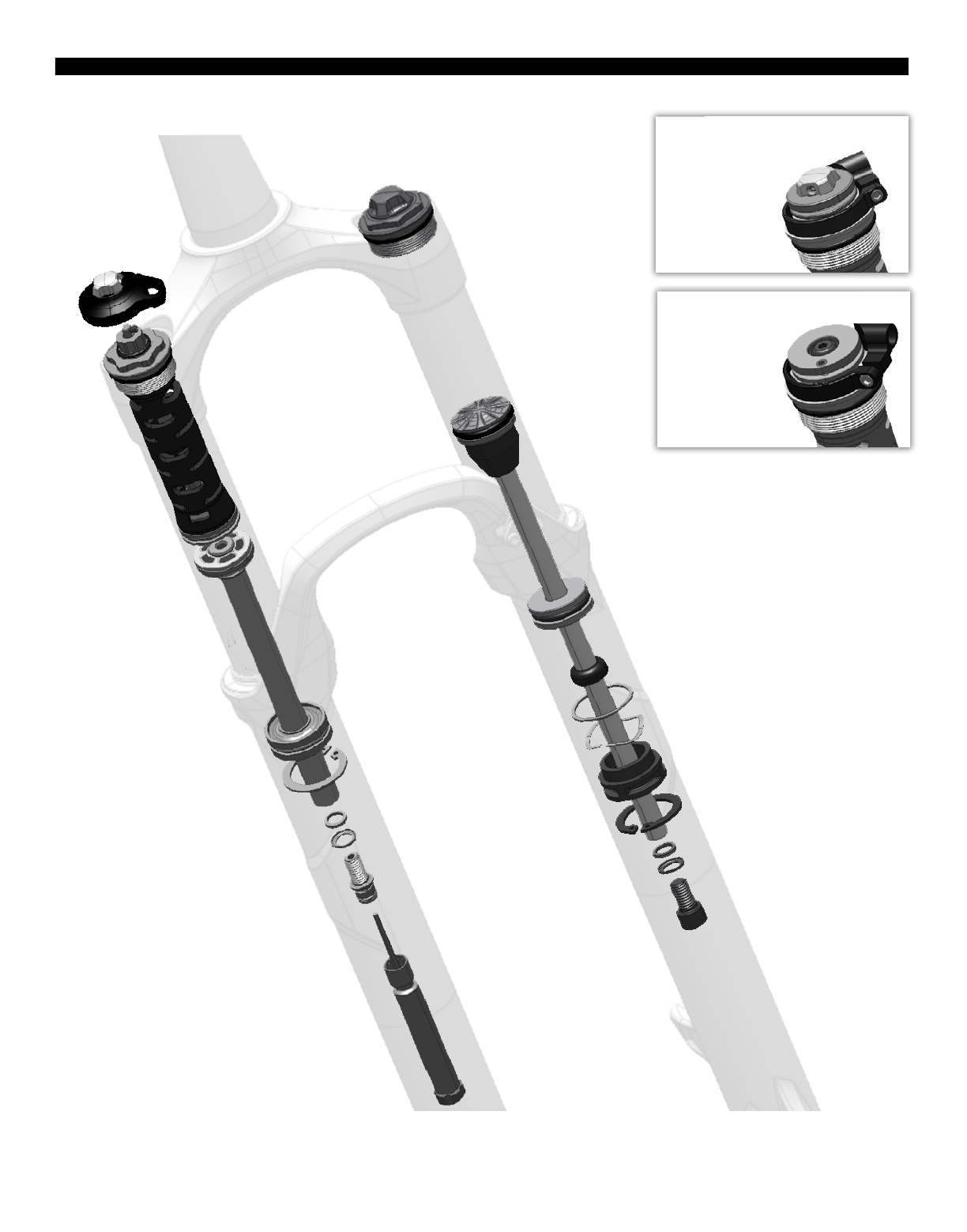
REBA EXPLODED VIEW
4REBA EXPLODED VIEW
RLT Remote
Rebound Piston
Compression Adjuster or Lockout
Damper Shaft
Air Shaft
Air Piston
Air Valve Cap
Floating Seal Head Topout Bumper
Topout Bumper
Cone
Spool
Spool
Cable Stop Collar
Cable Stop Collar
Floating Seal Head
Aluminum Support Washer
Wavy Washer
Air Shaft Guide
Rebound Seal Head
Snap Ring
Snap Ring
Crush Washer
Crush Washer
Crush Washer Retainer
Crush Washer Retainer
Shaft Bolt
Shaft Bolt
Rebound Adjuster
Lower Leg
RL Remote
Compression Damper
Gate Adjuster
Steerer Tube
Crown
Top Cap
Compression Piston

ROCKSHOX SUSPENSION SERVICE
We recommend that you have your RockShox suspension serviced by a qualified bicycle mechanic. Servicing RockShox suspension
requires knowledge of suspension components as well as the special tools and fluids used for service.
For exploded diagram and part number information, please refer to the Spare Parts Catalog available on our website at
sram.com/service. For order information, please contact your local SRAM distributor or dealer.
Information contained in this publication is subject to change at any time without prior notice. For the latest technical information,
please visit our website at sram.com/service.
Your product‘s appearance may dier from the pictures contained in this publication.
PARTS AND TOOLS NEEDED FOR SERVICE
đƫ Safety glasses
đƫ Nitrile gloves
đƫ Apron
đƫ Clean, lint-free rags
đƫ Oil pan
đƫ Isopropyl alcohol
đƫ RockShox 15wt suspension fluid
đƫ RockShox 5wt suspension fluid
đƫ Liquid O-Ring® PM600 military grease
đƫ Buzzy’s® Slick Honey bike grease
đƫ Shock pump
đƫ Seal installation tool
đƫ Downhill tire lever
đƫ Rubber mallet
đƫ Schrader valve core tool
đƫ 1.5, 2, 2.5, and 5 mm hex wrench
đƫ 1.5, 2, 2.5, and 5 mm hex bit socket
đƫ 24 mm socket wrench
đƫ Torque wrench
đƫ Large internal snap ring pliers
đƫ Pick
đƫ Long plastic or wooden dowel
đƫ Syringe
đƫ Optional travel change solo air spring assembly
SAFETY INSTRUCTIONS
Always wear safety glasses and nitrile gloves when working with suspension fluid.
Place an oil pan on the floor underneath the area where you will be working on the fork.
NOTICE
Do not scratch any sealing surfaces when servicing your suspension. Scratches can cause leaks.
When replacing o-rings, use your fingers or a pick to remove the o-ring. Clean the o-ring groove and apply grease to the new o-ring.
5ROCKSHOX SUSPENSION SERVICE
LOWER LEG REMOVAL
1 Remove the air valve cap from the top cap located on the
non-drive side fork leg.
2 Use a small hex wrench to depress the Schrader valve and release
all of the air pressure from the air chamber.
Use a Schrader valve tool to remove the valve core from the valve
body. Install a new Schrader valve.
CAUTION- EYE HAZARD
Verify all pressure is removed from the fork before proceeding.
Failure to do so can result in injury and/or damage to the fork.
3 Remove the external rebound adjuster knob by pulling it from the
shaft bolt at the bottom of the drive side fork leg.
4 Use a 5 mm hex wrench to loosen both shaft bolts 3 to 4 turns.
5 mm
6LOWER LEG REMOVAL
5 Place an oil pan beneath the fork to catch any draining fluid.
Insert a 5 mm hex wrench into the one of the shaft bolts. Use a
plastic mallet to firmly strike the wrench and free the bolt from the
lower leg. Remove the shaft bolt from the lower leg. Repeat this
procedure for the other shaft bolt.
6 Firmly pull the lower legs downward until fluid begins to drain.
Remove the lower leg from the fork by pulling it downward,
holding onto both legs or the brake arch.
If the lower legs do not slide out of the upper tubes or if fluid
doesn’t drain from either side, the press fit of the shaft(s) to the
lower leg may still be engaged. Reinstall the shaft bolts 2 to 3 turns
and repeat the previous step.
NOTICE
Do not hit the brake arch with any tool when removing the lower
leg as this could damage the fork.
7 Spray isopropyl alcohol on the inside and outside of the lower leg.
Wipe the outside of the lower leg with a rag.
Wrap a rag around a long dowel and insert it into the lower leg to
clean the inside of each lower leg.
5 mm
7LOWER LEG REMOVAL

LOWER LEG SEAL SERVICE
1 Place the tip of a downhill tire lever underneath the lower lip of the
dust wiper seal.
NOTICE
If using a flat head screwdriver, make sure it has a round shaft. A
screwdriver with a square shaft will damage the fork leg.
2 Stabilize the lower legs on a bench top or on the floor. Hold the
lower legs firmly and use downward force on the tool handle to
leverage the dust wiper seal out. Repeat on the other side.
NOTICE
Keep the lower leg assembly stable. Do not allow the lower legs
to twist in opposite directions, compress toward each other, or
be pulled apart. This will damage the lower leg.
3 Use your fingers to remove and discard the foam rings inside the
lower legs.
4 Soak the new foam rings in RockShox 15wt suspension fluid.
Reinstall new foam rings on the top bushings in the lower legs.
8LOWER LEG SEAL SERVICE

5 Use a seal installation tool to install the new dust wiper seals.
Position the dust wiper into the recessed side of the tool, so the
grooved side of the seal is visible.
6 Hold one of the lower legs and use the seal installation tool to push
the dust wiper seal evenly into the lower legs until there is no gap
between the dust wiper seal and lower legs.
9LOWER LEG SEAL SERVICE

SOLO AIR SPRING SERVICE
OPTIONAL TRAVEL CHANGE ADJUSTMENT
To change the travel in your suspension fork, replace the entire solo air spring assembly according to the directions below. For part
number information, please refer to the Spare Parts Catalog available on our website at sram.com/service. For ordering information,
please contact your local SRAM distributor or dealer.
Desired Travel Required Solo Air Spring Assembly Length for 26″ Required Solo Air Spring Assembly Length for 27.5″ and 29″
80 147.2 182.2
90 157.2 192.2
100 167.2 202.2
110 177.2 212.2
120 187.2 222.2
SOLO AIR SPRING REMOVAL
1 Use a small hex wrench to depress the Schrader valve and release
all of the air pressure from the air chamber.
CAUTION- EYE HAZARD
Verify all pressure is removed from the fork before proceeding.
Failure to do so can result in injury and/or damage to the fork.
2 Use a 24 mm socket wrench to remove the air spring top cap.
Once removed, clean the upper tube threads with a rag.
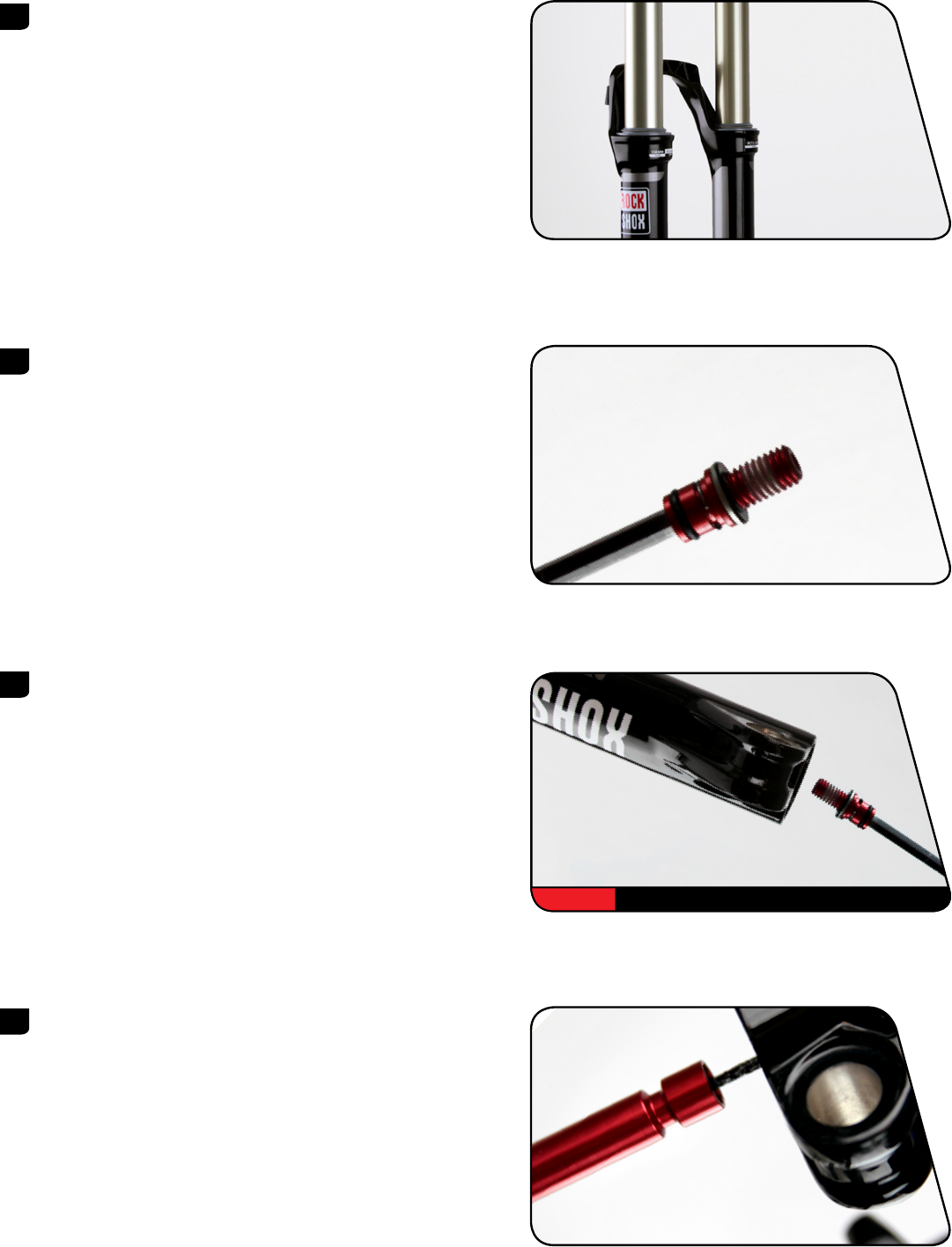
3 Use a pick to remove the top cap o-ring. Apply a small amount of
grease to a new top cap o-ring and install it. Apply a small amount
of grease to the top cap threads.
Do not scratch the top cap. Scratches can cause leaks.
24 mm
10 SOLO AIR SPRING SERVICE
4 Use a pick to remove and replace the air valve cap o-ring.
5 Place the tips of large internal snap ring pliers into eyelets of the
snap ring, located at the bottom of the non-drive side upper tube.
Press firmly on the pliers to push the air shaft guide into the upper
tube enough to compress and remove the snap ring.
Guide the snap ring over the air shaft to prevent scratching.
Scratches on the air shaft will allow air to bypass the seal head
into the lower legs, resulting in reduced spring performance.
6 Firmly pull on the air shaft to remove the air shaft assembly from
the upper tube. Clean and inspect the assembly for damage.
11 SOLO AIR SPRING REMOVAL

7 Spray isopropyl alcohol on the inside and outside of the upper
tube. Wipe the outside of the upper tube with a clean rag.
Wrap a rag around a long dowel and insert it into the upper tube
to clean inside the upper tube.
8 Remove the floating seal head, washers, floating seal head topout
bumper, and air shaft guide from the air shaft.
Spray isopropyl alcohol on the air shaft and clean it with a rag.
9 Use a pick to remove the inner and outer floating seal head o-rings.
Inspect the seal head for scratches. Spray isopropyl alcohol on the
seal head and clean it with a rag.
Apply a liberal amount of grease to the new o-rings and install
them.
Do not scratch the floating seal head. Scratches can cause leaks.
10 Use a pick to remove the air piston outer o-ring.
Inspect air piston for scratches. Spray isopropyl alcohol on the air
piston and clean it with a rag.
Apply a liberal amount of grease to the new o-ring and install it.
Do not scratch the air piston. Scratches can cause leaks.
12 SOLO AIR SPRING REMOVAL
11 Use your fingers to remove the bumper cone from the air shaft.
Install a new bumper cone onto the air shaft so it covers the
tension pin hole.
NOTICE
If the pin tension is protruding or not centered, replace the piston
assembly.
SOLO AIR SPRING INSTALLATION
1 Apply a liberal amount of grease to the inside of the upper tube,
from the end of the tube to approximately 60 mm into the tube.
2 Apply a liberal amount of grease to the air piston.
3 Apply a liberal amount of grease 40-60 mm around the air shaft.
Install the floating seal head, a new floating seal head topout
bumper, new aluminum support washer, new wavy washer and the
air shaft guide, in that order, onto the air shaft.
13 SOLO AIR SPRING INSTALLATION
4 Firmly push the air assembly into the bottom of the upper tube
while gently rocking the air shaft side to side.
Orient the washers so that the aluminum support washer goes into
the upper tube first, followed by the wavy washer.
5 Install the snap ring onto internal snap ring pliers. Use the pliers to
push the air shaft into the upper tube while installing the snap ring
into its groove. The air shaft guide should be situated between the
snap ring eyelets.
Make sure the snap ring is securely fastened in the snap ring
groove. Check this by using the snap ring pliers to rotate the
snap ring back and forth a couple of times, then firmly pulling
down on the air shaft.
Snap rings have a sharper-edged side and a rounder-edged side.
Installing snap rings with the sharper-edged side facing the tool
will allow for easier installation and removal.
6 Insert the top cap into the top of the upper tube. Use a torque
wrench with a 24 mm socket to tighten the top cap to
7.3 N·m (65 in-lb).
24 mm 7.3 N·m (65 in-lb)
14 SOLO AIR SPRING INSTALLATION
DAMPER SERVICE
COMPRESSION DAMPER REMOVAL
1 RLT: Use a 1.5 mm hex wrench to remove the gate adjuster set
screw. Remove the gate adjuster, compression adjuster knob, and
the o-ring seal.
RL: Use a 2.5 mm hex wrench to remove the compression adjuster
knob retention screw. Remove the compression adjuster knob.
Remote Only: Use a 2 mm hex wrench to loosen the cable pinch
bolt and remove the cable.
Use a 2 mm hex wrench to loosen the cable stop collar clamping
bolt. Remove the cable stop collar.
You do not need to remove the remote cable spool.
2.5 mm RL
1.5 mm RLT
2 mm RLT
2 mm RL
2 mm
15 DAMPER SERVICE
2 Use a 24 mm socket to loosen the compression damper top cap.
Remove the compression damper by pulling up and gently rocking
side to side. Clean the upper tube threads with a rag.
3 Use a pick or your fingers to remove the compression damper top
cap o-ring. Apply grease to the new o-ring and install it.
RLT Only: Install a new o-ring on the cam.
Do not scratch the top cap. Scratches can cause leaks.
4 Use a pick or your fingers to remove the compression damper
piston o-ring. Apply suspension fluid to the new o-ring and install
it.
Do not scratch the piston. Scratches may cause air to leak.
5 Remove the fork from the bicycle stand and pour the suspension
fluid into an oil pan.
24 mm
RLT
RL
16 COMPRESSION DAMPER REMOVAL
REBOUND DAMPER SERVICE
1 Clamp the fork into the bicycle stand. From the bottom of the
upper tube, push the rebound shaft in until enough shaft is
exposed to hold onto with your fingers.
Use internal snap ring pliers to remove the rebound damper seal
head snap ring.
2 Remove the rebound damper and seal head assembly from the
upper tube.
3 Spray isopropyl alcohol on the inside and outside of the upper
tube. Wipe the outside of the upper tube with a rag.
Wrap a rag around a long dowel and insert it into the upper tube
to clean inside the upper tube.
4 Install a new piston glide ring on the rebound damper.
17 REBOUND DAMPER SERVICE
5 Remove the rebound seal head from the damper shaft.
Use a pick to remove the inner and outer rebound seal head
o-rings. Inspect the rebound seal head for scratches and wipe it
with a rag.
Apply suspension fluid to the new o-rings and install.
Spray isopropyl alcohol on the rebound damper shaft and clean it
with a rag.
Do not scratch the seal head. Scratches can cause leaks.
6 Spray isopropyl alcohol on the rebound damper shaft and clean it
with a rag.
Install the rebound seal head onto the shaft.
7 Insert the rebound damper piston into the bottom of the upper
tube at an angle with the side opposite the glide ring split entering
first. Continue to angle and rotate until the glide ring is in the
upper tube.
18 REBOUND DAMPER SERVICE

8 Push the rebound seal head firmly into the upper tube until the
retaining ring groove is visible.
Push the rebound damper shaft into the seal head, until enough
shaft is exposed to hold onto with your fingers.
9 Use internal snap ring pliers to secure the snap ring into the
retaining ring groove.
Make sure the snap ring is securely fastened in the snap ring
groove. Check this by using the snap ring pliers to rotate the
snap ring back and forth a couple of times, then firmly pulling
down on the air shaft.
Snap rings have a sharper-edged side and a rounder-edged side.
Installing snap rings with the sharper-edged side facing the tool
will allow for easier installation and removal.
10 Clamp the fork vertically in the bicycle stand. Pull the rebound
damper shaft down to the fully extended position.
Use the chart to determine the amount of RockShox 5wt
suspension fluid to measure and pour into the drive side upper
tube.
Reba
RLT, RL 106 mL
RL3 111 mL
Suspension fluid volume is critical. Too much suspension fluid
reduces available travel, too little suspension fluid decreases
damping performance.
11 Turn the hex shaft to the unlocked position. Insert the compression
damper into the upper tube. Press down and rock side to side until
the damper is installed.
19 REBOUND DAMPER SERVICE
12 Use a torque wrench with a 24 mm socket to tighten the
compression damper to 7.3 N·m (65 in-lb).
COMPRESSION DAMPER INSTALLATION
1 RLT: Install a new o-ring on the cam, then install the compression
adjuster knob so the knob dial is against the hard stop.
Use a 1.5 mm hex bit socket to tighten the gate adjuster knob set
screw to 0.6 Nm (5 in-lb).
RL: Install the compression adjuster knob with the knob dial
against the hard stop.
Use a 2.5 mm hex bit socket to install the compression adjuster
knob retention screw to 1.4 Nm (12 in-lb).
Remote Only: Install the cable stop collar onto the top cap with
the cable stop facing toward the front of the fork, perpendicular to
the crown. Use a 2 mm hex bit socket to tighten the collar clamp
bolt to 1.4 Nm (12 in-lb).
24 mm 7.3 N·m (65 in-lb)
RLT
1.5 mm 0.6 Nm (5 in-lb)
RL
2.5 mm 1.4 Nm (12 in-lb)
2 mm 1.4 N·m (12 in-lb)
20 COMPRESSION DAMPER INSTALLATION
LOWER LEG INSTALLATION
1 Spray isopropyl alcohol on the upper tubes and clean them with a
rag.
2 Apply a liberal amount of Buzzy’s® Slick Honey grease to the inner
surfaces of the dust wiper seals.
Dust wipers may already be pregreased from the factory. If that is
the case, do not apply more grease.
3 Slide the lower leg assembly onto the upper tube assembly just
enough to engage the upper bushing with the upper tubes.
Make sure both dust wiper seals slide onto the tubes without
folding the outer lip of either seal.
4 Position the fork at a slight angle with the shaft bolt holes oriented
upward, then inject 5 mL of RockShox 15wt suspension fluid into
each lower leg through the shaft bolt hole.
21 LOWER LEG INSTALLATION
5 Slide the lower leg assembly along the upper tubes until it stops
and the spring and damper shafts are visible through the shaft bolt
holes. Wipe all excess fluid from the outer surface of the lower
legs.
6 Install a new o-ring into the top gland of a new shaft bolt. Install a
new spring clip in the lower gland of the shaft bolt.
Apply a thick layer of grease around the diameter of the bolt head
and o-ring.
Replace the crush washers and crush washer retainers.
Dirty or damaged crush washers can cause leaks.
7 Insert the shaft bolts into the lower legs through the threaded
shaft bolt holes.
Use a torque wrench with a 5 mm hex bit socket to tighten the
bolts to 7.3 N·m (65 in-lb).
8 Insert the external rebound damper knob into the rebound damper
shaft bolt until it is secure. Adjust the rebound.
5 mm 7.3 N·m (65 in-lb)
22 LOWER LEG INSTALLATION

9 Refer to the air chart on the fork lower leg and pressurize the air
spring to the appropriate pressure for your rider weight.
You may see a drop in the indicated air pressure on the pump gage
while filling the air spring, this is normal. Continue to fill the air
spring to the recommended air pressure.
10 Spray isopropyl alcohol on the entire fork and clean it with a rag.
23 LOWER LEG INSTALLATION

PUSHLOC™ REMOTE SERVICE
CABLE REMOVAL
1 Push the remote lever until it returns toward you.
2 RLT: Use a 2 mm hex wrench to loosen the cable pinch bolt on the
spool and pull the cable out of the cable end slot. Use pliers to
remove the cable end.
RL: Use a 2 mm hex wrench to loosen the cable pinch bolt on the
spool. Use pliers to remove the cable end.
3 Disconnect the cable from the damper and pull the cable housing
o the cable.
4 Use a 2 mm hex wrench to open the cable hatch cover.
Push the cable through the remote until the cable head is far
enough out of the lever to access.
2 mm RLT
2 mm RL
2 mm
24 PUSHLOC™ REMOTE SERVICE
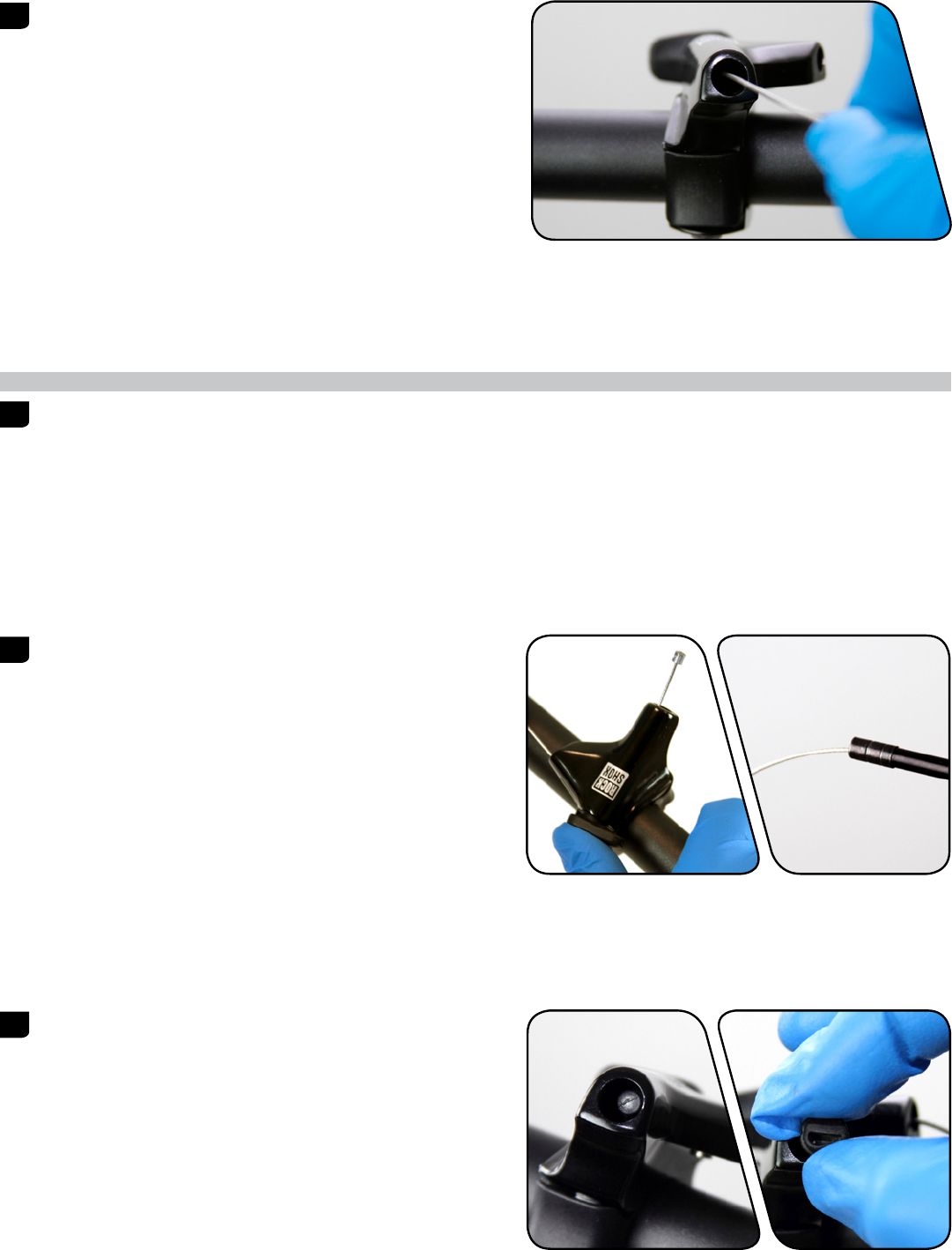
5 Pull the cable head to remove the cable from the remote system.
CABLE INSTALLATION
1 If replacing the cable housing, detach the cable housing and end
caps from the lever and the cable housing stop on the fork.
Attach the new housing and end caps to the remote lever and the
cable housing stop on the fork. Cut a length of shifter housing to
accommodate travel and suspension movement.
2 Hold the remote lever in and install the new shifter cable through
remote. Install the cable housing onto the new shifter cable.
3 Pull the cable until the cable head is seated in the remote lever.
With the cable head seated in the remote lever, close the cable
hatch cover and push the lever to return it to the unlocked
position.
25 CABLE INSTALLATION

4 RLT: Wrap the cable around the spool and insert it through the
cable fixing port. While firmly pulling the cable, use a 2 mm hex
wrench to tighten the cable pinch bolt to 0.9 Nm (8 in-lb).
Cut the excess cable, leaving 30 mm protruding from the cable
fixing port. Install a cable end fitting and tuck the cable end into
the slot in the spool.
RL: Wrap the cable around the spool. While firmly pulling the
cable, use a 2 mm hex wrench to tighten the cable pinch bolt to
0.9 Nm (8 in-lb).
Cut the excess cable and install a cable end fitting.
This concludes the service for RockShox Reba front suspension forks.
2 mm RLT
2 mm RL
26 CABLE INSTALLATION
2013
Reba Service Manual
GEN.0000000004216 Rev A © 2012 SRAM LLC

SRAM LLC WARRANTY
EXTENT OF LIMITED WARRANTY
!»#$%&'()’*&+$,-.)$’)$&’/*,&+’+$,$.01’2345′-(,,(0&)’.&)’%,*67#&)’&*’8$’/,$$’/,*9’6$/$#&)’.0’9(&$,.(:)’*,’-*,;9(0)+.%’/*,'(‘%$,.*6’*/’&-*'<$(,)'(/&$,’
*,.=.0(:’%7,#+()$>‘‘?+.)’-(,,(0&<‘*0:<‘(%%:.$)’&*’&+$’*,.=.0(:’*-0$,'(06′.)’0*&’&,(0)/$,(8:$>’@:(.9)’706$,’&+.)’-(,,(0&<’97)&’8$’9(6$’&+,*7=+’&+$’,$&(.:$,’
-+$,$’&+$’8.#<#:$’*,’&+$’2345’#*9%*0$0&’-()’%7,#+()$6>’A,.=.0(:’%,**/’*/’%7,#+()$’.)’,$B7.,$6>’Except’as’described’herein,’SRAM’makes’no’
other’warranties,’guaranties,’or’representations’of’any’type'(express’or’implied),’and’all’warranties'(including’any’implied’warranties’of’
reasonable’care,’merchantibility,’or’fitness’for’a’particular’purpose)’are’hereby’disclaimed.
LOCAL LAW
7KLVZDUUDQWVWDWHPHQWJLYHVWKHFXVWRPHUVSHFL¿FOHJDOULJKWV7KHFXVWRPHUPDDOVRKDYHRWKHUULJKWVZKLFKYDUIURPVWDWHWRVWDWH86$IURP
SURYLQFHWRSURYLQFH&DQDGDDQGIURPFRXQWUWRFRXQWUHOVHZKHUHLQWKHZRUOG
7RWKHH[WHQWWKDWWKLVZDUUDQWVWDWHPHQWLVLQFRQVLVWHQWZLWKWKHORFDOODZWKLVZDUUDQWVKDOOEHGHHPHGPRGL¿HGWREHFRQVLVWHQWZLWKVXFKODZXQGHU
VXFKORFDOODZFHUWDLQGLVFODLPHUVDQGOLPLWDWLRQVRIWKLVZDUUDQWVWDWHPHQWPDDSSOWRWKHFXVWRPHU)RUH[DPSOHVRPHVWDWHVLQWKH8QLWHG6WDWHV
RI$PHULFDDVZHOODVVRPHJRYHUQPHQWVRXWVLGHRIWKH8QLWHG6WDWHVLQFOXGLQJSURYLQFHVLQ&DQDGDPD
(>’C,$#:76$’&+$’6.)#:(.9$,)'(06′:.9.&(&.*0)’*/’&+.)’-(,,(0&<‘)&(&$9$0&’/,*9′:.9.&.0=’&+$’)&(&7&*,<‘,.=+&)’*/’&+$’#*0)79$,»
HJ8QLWHG.LQJGRP
8>’A&+$,-.)$’,$)&,.#&’&+$'(8.:.&<‘*/'(‘9(07/(#&7,$,’&*’$0/*,#$’)7#+’6.)#:(.9$,)’*,’:.9.&(&.*0)>
For’Australian’customers:
7KLV65$0OLPLWHGZDUUDQWLVSURYLGHGLQ$XVWUDOLDE65$0//&1RUWK.LQJVEXUWKÀRRU&KLFDJR,OOLQRLV86$7RPDNHDZDUUDQW
FODLPSOHDVHFRQWDFWWKHUHWDLOHUIURPZKRPRXSXUFKDVHGWKLV65$0SURGXFW$OWHUQDWLYHORXPDPDNHDFODLPEFRQWDFWLQJ65$0$XVWUDOLD
5(,#*’@*7,&1’3*-D.::$’EFGH1′47)&,(:.(>’I*,’D(:.6’#:(.9)’2345′-.::1′(&’.&)’*%&.*01’$.&+$,’,$%(.,’*,’,$%:(#$'<*7,’2345’%,*67#&>»40<‘$»%$0)$)’.0#7,,$6′.0′
PDNLQJWKHZDUUDQWFODLPDUHRXUUHVSRQVLELOLW7KHEHQH¿WVJLYHQEWKLVZDUUDQWDUHDGGLWLRQDOWRRWKHUULJKWVDQGUHPHGLHVWKDWRXPDKDYH
706$,’:(-)’,$:(&.0=’&*’*7,’%,*67#&)>»A7,’=**6)’#*9$’-.&+’=7(,(0&$$)’&+(&’#(00*&’8$’$»#:76$6’706$,’&+$’47)&,(:.(0’@*0)79$,’J(->»K*7′(,$’$0&.&:$6’&*’
(‘,$%:(#$9$0&’*,’,$/706’/*,'(‘9(L*,’/(.:7,$'(06’/*,’#*9%$0)(&.*0’/*,'(0<‘*&+$,’,$()*0(8:<‘/*,$)$$(8:$’:*))’*,’6(9(=$>»K*7′(,$'(:)*’$0&.&:$6’&*’+(D$’&+$’
=**6)’,$%(.,$6’*,’,$%:(#$6′./’&+$’=**6)’/(.:’&*’8$’*/'(##$%&(8:$’B7(:.&<‘(06’&+$’/(.:7,$’6*$)’0*&'(9*70&’&*'(‘9(L*,’/(.:7,$>
LIMITATIONS OF LIABILITY
7RWKHH[WHQWDOORZHGEORFDOODZH[FHSWIRUWKHREOLJDWLRQVVSHFL¿FDOOVHWIRUWKLQWKLVZDUUDQWVWDWHPHQWLQQRHYHQWVKDOO65$0RULWVWKLUGSDUW
)7%%:.$,)’8$’:.(8:$’/*,’6.,$#&1′.06.,$#&1′)%$#.(:1′.0#.6$0&(:1’*,’#*0)$B7$0&.(:’6(9(=$)>’
LIMITATIONS OF WARRANTY
?+.)’-(,,(0&<‘6*$)’0*&'(%%:<‘&*’%,*67#&)’&+(&’+(D$’8$$0’.0#*,,$#&:<‘.0)&(::$6′(06M*,'(6L7)&$6′(##*,6.0=’&*’&+$’,$)%$#&.D$’2345’7)$,’9(07(:>’?+$’2345′
7)$,’9(07(:)’#(0’8$’/*706’*0:.0$'(&’),(9>#*91′,*#;)+*»>#*91′(D.68.;$>#*91’&,7D(&.D>#*91’*,’N.%%>#*9>
?+.)’-(,,(0&<‘6*$)’0*&'(%%:<‘&*’6(9(=$’&*’&+$’%,*67#&’#(7)$6’8<‘(‘#,()+1′.9%(#&1′(87)$’*/’&+$’%,*67#&1’0*0O#*9%:.(0#$’-.&+’9(07/(#&7,$,)’
VSHFL¿FDWLRQVRIXVDJHRUDQRWKHUFLUFXPVWDQFHVLQZKLFKWKHSURGXFWKDVEHHQVXEMHFWHGWRIRUFHVRUORDGVEHRQGLWVGHVLJQ
7KLVZDUUDQWGRHVQRWDSSOZKHQWKHSURGXFWKDVEHHQPRGL¿HGLQFOXGLQJEXWQRWOLPLWHGWRDQDWWHPSWWRRSHQRUUHSDLUDQHOHFWURQLFDQG
$:$#&,*0.#’,$:(&$6’#*9%*0$0&)1′.0#:76.0=’&+$’9*&*,1’#*0&,*::$,1’8(&&$,<‘%(#;)1′-.,.0=’+(,0$))$)1’)-.&#+$)1′(06’#+(,=$,)>
?+.)’-(,,(0&<‘6*$)’0*&'(%%:<‘-+$0’&+$’)$,.(:’0798$,’*,’%,*67#&.*0’#*6$’+()’8$$0’6$:.8$,(&$:<‘(:&$,$61’6$/(#$6’*,’,$9*D$6>
?+.)’-(,,(0&<‘6*$)’0*&'(%%:<‘&*’0*,9(:’-$(,'(06’&$(,>’P$(,'(06’&$(,’%(,&)'(,$’)78L$#&’&*’6(9(=$'()'(‘,$)7:&’*/’0*,9(:’7)$1’/(.:7,$’&*’)$,D.#$'(##*,6.0=’
&*’2345′,$#*99$06(&.*0)'(06M*,’,.6.0=’*,’.0)&(::(&.*0′.0’#*06.&.*0)’*,'(%%:.#(&.*0)’*&+$,’&+(0′,$#*99$06$6>
:HDUDQGWHDUSDUWVDUHLGHQWL¿HGDV
Notwithstanding’anything’else’set’forth’herein1’&+.)’-(,,(0&<‘.)’:.9.&$6’&*’*0$'<$(,’/*,'(::’$:$#&,*0.#'(06’$:$#&,*0.#’,$:(&$6’#*9%*0$0&)’.0#:76.0=’
9*&*,)1’#*0&,*::$,)1’8(&&$,<‘%(#;)1′-.,.0=’+(,0$))$)1′)-.&#+$)1′(06’#+(,=$,)>’?+$’8(&&$,<‘%(#;'(06’#+(,=$,’-(,,(0&<‘6*$)’0*&’.0#:76$’6(9(=$’/,*9′
%*-$,’)7,=$)1’7)$’*/’.9%,*%$,’#+(,=$,1′.9%,*%$,’9(.0&$0(0#$1’*,’)7#+’*&+$,’9.)7)$>
?+.)’-(,,(0&<‘)+(::’0*&’#*D$,’6(9(=$)’#(7)$6’8<‘&+$’7)$’*/’%(,&)’*/’6.//$,$0&’9(07/(#&7,$,)>
?+.)’-(,,(0&<‘)+(::’0*&’#*D$,’6(9(=$)’#(7)$6’8<‘&+$’7)$’*/’%(,&)’&+(&'(,$’0*&’#*9%(&.8:$1’)7.&(8:$'(06M*,'(7&+*,.)$6’8<‘2345’/*,’7)$’-.&+’2345′
#*9%*0$0&)>
7KLVZDUUDQWVKDOOQRWFRYHUGDPDJHVUHVXOWLQJIURPFRPPHUFLDOUHQWDOXVH
Q7)&’)$(:)
R7)+.0=)
4.,’)$(:.0=’*O,.0=)
S:.6$’,.0=)
3788$,’9*D.0=’%(,&)
I*(9′,.0=)
3$(,’)+*#;’9*70&.0=’+(,6-(,$’
(06’9(.0′)$(:)
8SSHUWXEHVVWDQFKLRQV
6WULSSHGWKUHDGVEROWVDOXPLQLXP
WLWDQLXPPDJQHVLXPRUVWHHO
R,(;$’):$$D$)
R,(;$’%(6)
@+(.0)
2%,*#;$&)
@())$&&$)
6KLIWHUDQGEUDNHFDEOHVLQQHU
DQGRXWHU
T(06:$8(,’=,.%)
2+./&$,’=,.%)
U*#;$<‘-+$$:)
Q.)#’8,(;$’,*&*,)
P+$$:’8,(;.0=’)7,/(#$)
R*&&*9*7&’%(6)
R$(,.0=)
R$(,.0=’,(#$)
C(-:)
?,(0)9.)).*0’=$(,)
2%*;$)
I,$$’+78)
4$,*’8(,’%(6)
@*,,*).*0
?**:)
5*&*,)
R(&&$,.$)
TABLE OF CONTENTS
REBA EXPLODED VIEW ………………………………………………………………………………………………………………………………………………. 4
ROCKSHOX SUSPENSION SERVICE …………………………………………………………………………………………………………………………….. 5
PARTS AND TOOLS NEEDED FOR SERVICE ……………………………………………………………………………………………………………………………………………………….5
LOWER LEG REMOVAL ………………………………………………………………………………………………………………………………………………… 6
LOWER LEG SEAL SERVICE …………………………………………………………………………………………………………………………………………………………………………………… 8
SOLO AIR SPRING SERVICE ………………………………………………………………………………………………………………………………………. 10
OPTIONAL TRAVEL CHANGE ADJUSTMENT ……………………………………………………………………………………………………………………………………………………10
SOLO AIR SPRING REMOVAL ………………………………………………………………………………………………………………………………………………………………………………..10
SOLO AIR SPRING INSTALLATION ………………………………………………………………………………………………………………………………………………………………………. 13
DAMPER SERVICE ……………………………………………………………………………………………………………………………………………………….15
COMPRESSION DAMPER REMOVAL ……………………………………………………………………………………………………………………………………………………………………15
REBOUND DAMPER SERVICE ………………………………………………………………………………………………………………………………………………………………………………. 17
COMPRESSION DAMPER INSTALLATION ………………………………………………………………………………………………………………………………………………………….20
LOWER LEG INSTALLATION ………………………………………………………………………………………………………………………………………..21
PUSHLOC™ REMOTE SERVICE …………………………………………………………………………………………………………………………………..24
CABLE REMOVAL …………………………………………………………………………………………………………………………………………………………………………………………………….24
CABLE INSTALLATION …………………………………………………………………………………………………………………………………………………………………………………………..25

SAFETY FIRST!
We care about YOU. Please, always wear your safety glasses and
protective gloves when servicing RockShox products.
Protect yourself! Wear your safety gear!
REBA EXPLODED VIEW
4REBA EXPLODED VIEW
RLT Remote
Rebound Piston
Compression Adjuster or Lockout
Damper Shaft
Air Shaft
Air Piston
Air Valve Cap
Floating Seal Head Topout Bumper
Topout Bumper
Cone
Spool
Spool
Cable Stop Collar
Cable Stop Collar
Floating Seal Head
Aluminum Support Washer
Wavy Washer
Air Shaft Guide
Rebound Seal Head
Snap Ring
Snap Ring
Crush Washer
Crush Washer
Crush Washer Retainer
Crush Washer Retainer
Shaft Bolt
Shaft Bolt
Rebound Adjuster
Lower Leg
RL Remote
Compression Damper
Gate Adjuster
Steerer Tube
Crown
Top Cap
Compression Piston

ROCKSHOX SUSPENSION SERVICE
We recommend that you have your RockShox suspension serviced by a qualified bicycle mechanic. Servicing RockShox suspension
requires knowledge of suspension components as well as the special tools and fluids used for service.
For exploded diagram and part number information, please refer to the Spare Parts Catalog available on our website at
sram.com/service. For order information, please contact your local SRAM distributor or dealer.
Information contained in this publication is subject to change at any time without prior notice. For the latest technical information,
please visit our website at sram.com/service.
Your product‘s appearance may dier from the pictures contained in this publication.
PARTS AND TOOLS NEEDED FOR SERVICE
đƫ Safety glasses
đƫ Nitrile gloves
đƫ Apron
đƫ Clean, lint-free rags
đƫ Oil pan
đƫ Isopropyl alcohol
đƫ RockShox 15wt suspension fluid
đƫ RockShox 5wt suspension fluid
đƫ Liquid O-Ring® PM600 military grease
đƫ Buzzy’s® Slick Honey bike grease
đƫ Shock pump
đƫ Seal installation tool
đƫ Downhill tire lever
đƫ Rubber mallet
đƫ Schrader valve core tool
đƫ 1.5, 2, 2.5, and 5 mm hex wrench
đƫ 1.5, 2, 2.5, and 5 mm hex bit socket
đƫ 24 mm socket wrench
đƫ Torque wrench
đƫ Large internal snap ring pliers
đƫ Pick
đƫ Long plastic or wooden dowel
đƫ Syringe
đƫ Optional travel change solo air spring assembly
SAFETY INSTRUCTIONS
Always wear safety glasses and nitrile gloves when working with suspension fluid.
Place an oil pan on the floor underneath the area where you will be working on the fork.
NOTICE
Do not scratch any sealing surfaces when servicing your suspension. Scratches can cause leaks.
When replacing o-rings, use your fingers or a pick to remove the o-ring. Clean the o-ring groove and apply grease to the new o-ring.
5ROCKSHOX SUSPENSION SERVICE

LOWER LEG REMOVAL
1 Remove the air valve cap from the top cap located on the
non-drive side fork leg.
2 Use a small hex wrench to depress the Schrader valve and release
all of the air pressure from the air chamber.
Use a Schrader valve tool to remove the valve core from the valve
body. Install a new Schrader valve.
CAUTION- EYE HAZARD
Verify all pressure is removed from the fork before proceeding.
Failure to do so can result in injury and/or damage to the fork.
3 Remove the external rebound adjuster knob by pulling it from the
shaft bolt at the bottom of the drive side fork leg.
4 Use a 5 mm hex wrench to loosen both shaft bolts 3 to 4 turns.
5 mm
6LOWER LEG REMOVAL

5 Place an oil pan beneath the fork to catch any draining fluid.
Insert a 5 mm hex wrench into the one of the shaft bolts. Use a
plastic mallet to firmly strike the wrench and free the bolt from the
lower leg. Remove the shaft bolt from the lower leg. Repeat this
procedure for the other shaft bolt.
6 Firmly pull the lower legs downward until fluid begins to drain.
Remove the lower leg from the fork by pulling it downward,
holding onto both legs or the brake arch.
If the lower legs do not slide out of the upper tubes or if fluid
doesn’t drain from either side, the press fit of the shaft(s) to the
lower leg may still be engaged. Reinstall the shaft bolts 2 to 3 turns
and repeat the previous step.
NOTICE
Do not hit the brake arch with any tool when removing the lower
leg as this could damage the fork.
7 Spray isopropyl alcohol on the inside and outside of the lower leg.
Wipe the outside of the lower leg with a rag.
Wrap a rag around a long dowel and insert it into the lower leg to
clean the inside of each lower leg.
5 mm
7LOWER LEG REMOVAL
LOWER LEG SEAL SERVICE
1 Place the tip of a downhill tire lever underneath the lower lip of the
dust wiper seal.
NOTICE
If using a flat head screwdriver, make sure it has a round shaft. A
screwdriver with a square shaft will damage the fork leg.
2 Stabilize the lower legs on a bench top or on the floor. Hold the
lower legs firmly and use downward force on the tool handle to
leverage the dust wiper seal out. Repeat on the other side.
NOTICE
Keep the lower leg assembly stable. Do not allow the lower legs
to twist in opposite directions, compress toward each other, or
be pulled apart. This will damage the lower leg.
3 Use your fingers to remove and discard the foam rings inside the
lower legs.
4 Soak the new foam rings in RockShox 15wt suspension fluid.
Reinstall new foam rings on the top bushings in the lower legs.
8LOWER LEG SEAL SERVICE
5 Use a seal installation tool to install the new dust wiper seals.
Position the dust wiper into the recessed side of the tool, so the
grooved side of the seal is visible.
6 Hold one of the lower legs and use the seal installation tool to push
the dust wiper seal evenly into the lower legs until there is no gap
between the dust wiper seal and lower legs.
9LOWER LEG SEAL SERVICE
SOLO AIR SPRING SERVICE
OPTIONAL TRAVEL CHANGE ADJUSTMENT
To change the travel in your suspension fork, replace the entire solo air spring assembly according to the directions below. For part
number information, please refer to the Spare Parts Catalog available on our website at sram.com/service. For ordering information,
please contact your local SRAM distributor or dealer.
Desired Travel Required Solo Air Spring Assembly Length for 26″ Required Solo Air Spring Assembly Length for 27.5″ and 29″
80 147.2 182.2
90 157.2 192.2
100 167.2 202.2
110 177.2 212.2
120 187.2 222.2
SOLO AIR SPRING REMOVAL
1 Use a small hex wrench to depress the Schrader valve and release
all of the air pressure from the air chamber.
CAUTION- EYE HAZARD
Verify all pressure is removed from the fork before proceeding.
Failure to do so can result in injury and/or damage to the fork.
2 Use a 24 mm socket wrench to remove the air spring top cap.
Once removed, clean the upper tube threads with a rag.
3 Use a pick to remove the top cap o-ring. Apply a small amount of
grease to a new top cap o-ring and install it. Apply a small amount
of grease to the top cap threads.
Do not scratch the top cap. Scratches can cause leaks.
24 mm
10 SOLO AIR SPRING SERVICE

4 Use a pick to remove and replace the air valve cap o-ring.
5 Place the tips of large internal snap ring pliers into eyelets of the
snap ring, located at the bottom of the non-drive side upper tube.
Press firmly on the pliers to push the air shaft guide into the upper
tube enough to compress and remove the snap ring.
Guide the snap ring over the air shaft to prevent scratching.
Scratches on the air shaft will allow air to bypass the seal head
into the lower legs, resulting in reduced spring performance.
6 Firmly pull on the air shaft to remove the air shaft assembly from
the upper tube. Clean and inspect the assembly for damage.
11 SOLO AIR SPRING REMOVAL
7 Spray isopropyl alcohol on the inside and outside of the upper
tube. Wipe the outside of the upper tube with a clean rag.
Wrap a rag around a long dowel and insert it into the upper tube
to clean inside the upper tube.
8 Remove the floating seal head, washers, floating seal head topout
bumper, and air shaft guide from the air shaft.
Spray isopropyl alcohol on the air shaft and clean it with a rag.
9 Use a pick to remove the inner and outer floating seal head o-rings.
Inspect the seal head for scratches. Spray isopropyl alcohol on the
seal head and clean it with a rag.
Apply a liberal amount of grease to the new o-rings and install
them.
Do not scratch the floating seal head. Scratches can cause leaks.
10 Use a pick to remove the air piston outer o-ring.
Inspect air piston for scratches. Spray isopropyl alcohol on the air
piston and clean it with a rag.
Apply a liberal amount of grease to the new o-ring and install it.
Do not scratch the air piston. Scratches can cause leaks.
12 SOLO AIR SPRING REMOVAL

11 Use your fingers to remove the bumper cone from the air shaft.
Install a new bumper cone onto the air shaft so it covers the
tension pin hole.
NOTICE
If the pin tension is protruding or not centered, replace the piston
assembly.
SOLO AIR SPRING INSTALLATION
1 Apply a liberal amount of grease to the inside of the upper tube,
from the end of the tube to approximately 60 mm into the tube.
2 Apply a liberal amount of grease to the air piston.
3 Apply a liberal amount of grease 40-60 mm around the air shaft.
Install the floating seal head, a new floating seal head topout
bumper, new aluminum support washer, new wavy washer and the
air shaft guide, in that order, onto the air shaft.
13 SOLO AIR SPRING INSTALLATION

4 Firmly push the air assembly into the bottom of the upper tube
while gently rocking the air shaft side to side.
Orient the washers so that the aluminum support washer goes into
the upper tube first, followed by the wavy washer.
5 Install the snap ring onto internal snap ring pliers. Use the pliers to
push the air shaft into the upper tube while installing the snap ring
into its groove. The air shaft guide should be situated between the
snap ring eyelets.
Make sure the snap ring is securely fastened in the snap ring
groove. Check this by using the snap ring pliers to rotate the
snap ring back and forth a couple of times, then firmly pulling
down on the air shaft.
Snap rings have a sharper-edged side and a rounder-edged side.
Installing snap rings with the sharper-edged side facing the tool
will allow for easier installation and removal.
6 Insert the top cap into the top of the upper tube. Use a torque
wrench with a 24 mm socket to tighten the top cap to
7.3 N·m (65 in-lb).
24 mm 7.3 N·m (65 in-lb)
14 SOLO AIR SPRING INSTALLATION

DAMPER SERVICE
COMPRESSION DAMPER REMOVAL
1 RLT: Use a 1.5 mm hex wrench to remove the gate adjuster set
screw. Remove the gate adjuster, compression adjuster knob, and
the o-ring seal.
RL: Use a 2.5 mm hex wrench to remove the compression adjuster
knob retention screw. Remove the compression adjuster knob.
Remote Only: Use a 2 mm hex wrench to loosen the cable pinch
bolt and remove the cable.
Use a 2 mm hex wrench to loosen the cable stop collar clamping
bolt. Remove the cable stop collar.
You do not need to remove the remote cable spool.
2.5 mm RL
1.5 mm RLT
2 mm RLT
2 mm RL
2 mm
15 DAMPER SERVICE

2 Use a 24 mm socket to loosen the compression damper top cap.
Remove the compression damper by pulling up and gently rocking
side to side. Clean the upper tube threads with a rag.
3 Use a pick or your fingers to remove the compression damper top
cap o-ring. Apply grease to the new o-ring and install it.
RLT Only: Install a new o-ring on the cam.
Do not scratch the top cap. Scratches can cause leaks.
4 Use a pick or your fingers to remove the compression damper
piston o-ring. Apply suspension fluid to the new o-ring and install
it.
Do not scratch the piston. Scratches may cause air to leak.
5 Remove the fork from the bicycle stand and pour the suspension
fluid into an oil pan.
24 mm
RLT
RL
16 COMPRESSION DAMPER REMOVAL

REBOUND DAMPER SERVICE
1 Clamp the fork into the bicycle stand. From the bottom of the
upper tube, push the rebound shaft in until enough shaft is
exposed to hold onto with your fingers.
Use internal snap ring pliers to remove the rebound damper seal
head snap ring.
2 Remove the rebound damper and seal head assembly from the
upper tube.
3 Spray isopropyl alcohol on the inside and outside of the upper
tube. Wipe the outside of the upper tube with a rag.
Wrap a rag around a long dowel and insert it into the upper tube
to clean inside the upper tube.
4 Install a new piston glide ring on the rebound damper.
17 REBOUND DAMPER SERVICE

5 Remove the rebound seal head from the damper shaft.
Use a pick to remove the inner and outer rebound seal head
o-rings. Inspect the rebound seal head for scratches and wipe it
with a rag.
Apply suspension fluid to the new o-rings and install.
Spray isopropyl alcohol on the rebound damper shaft and clean it
with a rag.
Do not scratch the seal head. Scratches can cause leaks.
6 Spray isopropyl alcohol on the rebound damper shaft and clean it
with a rag.
Install the rebound seal head onto the shaft.
7 Insert the rebound damper piston into the bottom of the upper
tube at an angle with the side opposite the glide ring split entering
first. Continue to angle and rotate until the glide ring is in the
upper tube.
18 REBOUND DAMPER SERVICE
8 Push the rebound seal head firmly into the upper tube until the
retaining ring groove is visible.
Push the rebound damper shaft into the seal head, until enough
shaft is exposed to hold onto with your fingers.
9 Use internal snap ring pliers to secure the snap ring into the
retaining ring groove.
Make sure the snap ring is securely fastened in the snap ring
groove. Check this by using the snap ring pliers to rotate the
snap ring back and forth a couple of times, then firmly pulling
down on the air shaft.
Snap rings have a sharper-edged side and a rounder-edged side.
Installing snap rings with the sharper-edged side facing the tool
will allow for easier installation and removal.
10 Clamp the fork vertically in the bicycle stand. Pull the rebound
damper shaft down to the fully extended position.
Use the chart to determine the amount of RockShox 5wt
suspension fluid to measure and pour into the drive side upper
tube.
Reba
RLT, RL 106 mL
RL3 111 mL
Suspension fluid volume is critical. Too much suspension fluid
reduces available travel, too little suspension fluid decreases
damping performance.
11 Turn the hex shaft to the unlocked position. Insert the compression
damper into the upper tube. Press down and rock side to side until
the damper is installed.
19 REBOUND DAMPER SERVICE

12 Use a torque wrench with a 24 mm socket to tighten the
compression damper to 7.3 N·m (65 in-lb).
COMPRESSION DAMPER INSTALLATION
1 RLT: Install a new o-ring on the cam, then install the compression
adjuster knob so the knob dial is against the hard stop.
Use a 1.5 mm hex bit socket to tighten the gate adjuster knob set
screw to 0.6 Nm (5 in-lb).
RL: Install the compression adjuster knob with the knob dial
against the hard stop.
Use a 2.5 mm hex bit socket to install the compression adjuster
knob retention screw to 1.4 Nm (12 in-lb).
Remote Only: Install the cable stop collar onto the top cap with
the cable stop facing toward the front of the fork, perpendicular to
the crown. Use a 2 mm hex bit socket to tighten the collar clamp
bolt to 1.4 Nm (12 in-lb).
24 mm 7.3 N·m (65 in-lb)
RLT
1.5 mm 0.6 Nm (5 in-lb)
RL
2.5 mm 1.4 Nm (12 in-lb)
2 mm 1.4 N·m (12 in-lb)
20 COMPRESSION DAMPER INSTALLATION

LOWER LEG INSTALLATION
1 Spray isopropyl alcohol on the upper tubes and clean them with a
rag.
2 Apply a liberal amount of Buzzy’s® Slick Honey grease to the inner
surfaces of the dust wiper seals.
Dust wipers may already be pregreased from the factory. If that is
the case, do not apply more grease.
3 Slide the lower leg assembly onto the upper tube assembly just
enough to engage the upper bushing with the upper tubes.
Make sure both dust wiper seals slide onto the tubes without
folding the outer lip of either seal.
4 Position the fork at a slight angle with the shaft bolt holes oriented
upward, then inject 5 mL of RockShox 15wt suspension fluid into
each lower leg through the shaft bolt hole.
21 LOWER LEG INSTALLATION

5 Slide the lower leg assembly along the upper tubes until it stops
and the spring and damper shafts are visible through the shaft bolt
holes. Wipe all excess fluid from the outer surface of the lower
legs.
6 Install a new o-ring into the top gland of a new shaft bolt. Install a
new spring clip in the lower gland of the shaft bolt.
Apply a thick layer of grease around the diameter of the bolt head
and o-ring.
Replace the crush washers and crush washer retainers.
Dirty or damaged crush washers can cause leaks.
7 Insert the shaft bolts into the lower legs through the threaded
shaft bolt holes.
Use a torque wrench with a 5 mm hex bit socket to tighten the
bolts to 7.3 N·m (65 in-lb).
8 Insert the external rebound damper knob into the rebound damper
shaft bolt until it is secure. Adjust the rebound.
5 mm 7.3 N·m (65 in-lb)
22 LOWER LEG INSTALLATION

9 Refer to the air chart on the fork lower leg and pressurize the air
spring to the appropriate pressure for your rider weight.
You may see a drop in the indicated air pressure on the pump gage
while filling the air spring, this is normal. Continue to fill the air
spring to the recommended air pressure.
10 Spray isopropyl alcohol on the entire fork and clean it with a rag.
23 LOWER LEG INSTALLATION
PUSHLOC™ REMOTE SERVICE
CABLE REMOVAL
1 Push the remote lever until it returns toward you.
2 RLT: Use a 2 mm hex wrench to loosen the cable pinch bolt on the
spool and pull the cable out of the cable end slot. Use pliers to
remove the cable end.
RL: Use a 2 mm hex wrench to loosen the cable pinch bolt on the
spool. Use pliers to remove the cable end.
3 Disconnect the cable from the damper and pull the cable housing
o the cable.
4 Use a 2 mm hex wrench to open the cable hatch cover.
Push the cable through the remote until the cable head is far
enough out of the lever to access.
2 mm RLT
2 mm RL
2 mm
24 PUSHLOC™ REMOTE SERVICE

5 Pull the cable head to remove the cable from the remote system.
CABLE INSTALLATION
1 If replacing the cable housing, detach the cable housing and end
caps from the lever and the cable housing stop on the fork.
Attach the new housing and end caps to the remote lever and the
cable housing stop on the fork. Cut a length of shifter housing to
accommodate travel and suspension movement.
2 Hold the remote lever in and install the new shifter cable through
remote. Install the cable housing onto the new shifter cable.
3 Pull the cable until the cable head is seated in the remote lever.
With the cable head seated in the remote lever, close the cable
hatch cover and push the lever to return it to the unlocked
position.
25 CABLE INSTALLATION
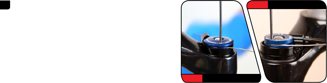
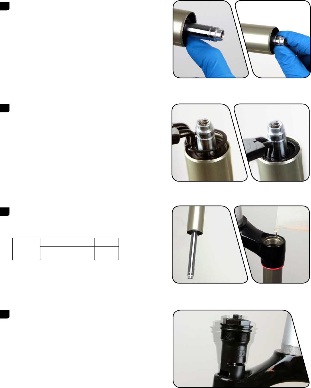
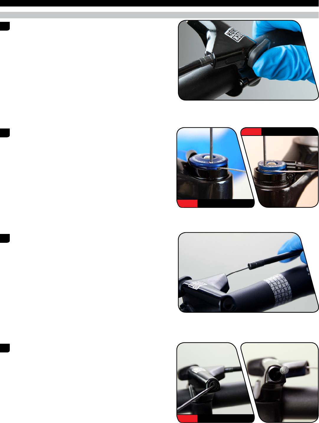
4 RLT: Wrap the cable around the spool and insert it through the
cable fixing port. While firmly pulling the cable, use a 2 mm hex
wrench to tighten the cable pinch bolt to 0.9 Nm (8 in-lb).
Cut the excess cable, leaving 30 mm protruding from the cable
fixing port. Install a cable end fitting and tuck the cable end into
the slot in the spool.
RL: Wrap the cable around the spool. While firmly pulling the
cable, use a 2 mm hex wrench to tighten the cable pinch bolt to
0.9 Nm (8 in-lb).
Cut the excess cable and install a cable end fitting.
This concludes the service for RockShox Reba front suspension forks.
2 mm RLT
2 mm RL
26 CABLE INSTALLATION

Rock Shox Reba
Устройство и ремонт своими руками (Любительский мануал)
ОГЛАВЛЕНИЕ:
1. Общие сведения и устройство вилки
2. Разборка вилки
3. Подготовка к покраске и покраска
4. Изменение хода вилки
5. Сборка вилки
6. Варианты накачивания воздушных камер
7. Резюме
P.S. Букв в тексте много, для тех кому оно не нужно просто резюмирую:
Я перебрал полностью свою вилку с покраской + замена масла, сальников
+ увеличение хода вилки с 100 мм до 115 мм с улучшением динамических характеристик
+ к тому-же при наклейке фирменных наклеек моя вилка 2006 года автоматически становиться вилкой 2009 года рождения.
На лицо махинация с продажной ценой ![]()
Одной из мотиваций переборки вилки дома самому стала цена мастерских: 250грн. ![]()
Скажу сразу: полная переборка вилки с заменой масла занимает максимум 1 — 1,5 часа свободного времени! ![]()
Теперь как говориться у меня очередной «Level UP»! ![]()
Из оставшихся частей велосипеда я еще не залазил в гидравлические тормоза и подшипники во втулках.
Будет скучно – залезу
ДО:_____________________________________________________________ПОСЛЕ:____________________
ОБЩИЕ СВЕДЕНИЯ и УСТРОЙСТВО ВИЛКИ
Вилка Rock Shox Reba представляет собой самую совершенную конструкцию пневматической подвески: упругим элементом выступают независимые позитивная и негативная воздушные камеры, которые работают на сжатие и отбой, поглощая ударные нагрузки и уменьшая амплитуду перемещений (в левой ноге), гасящим – открытая масляная ванна, которая смягчает и замедляет сжатие и отбой, уменьшая вертикальные ускорения и демпфируя колебания (в правой ноге). Заявленный ход вилки составляет 100 мм.
Вилка имеет широчайшие возможности настройки:
— регулировку жёсткости сжатия за счёт изменения давления воздуха в позитивной воздушной камере;
— регулировку мягкости отбоя за счёт изменения давления воздуха в негативной воздушной камере;
— настройку прелоада и усилия страгивания благодаря созданию разности давлений в независимых воздушных камерах (в интервале 1 атм);
— регулировку демпфирования сжатия вплоть до полной блокировки;
— регулировку демпфирования отбоя;
— изменение качества демпфирования за счёт замены вязкости и объёма масла (в диапазоне +/- 5 мл).
Общая структура вилки: 
Система с независимыми воздушными камерами и раздельными ниппелями для их накачки носит название Dual Air и является самой совершенной системой воздушной амортизации.
Во-первых, благодаря тому, что камеры внутри не сообщаются и при сжатии/отбое вилки воздух не переходит из одной камеры в другую, мы получаем прогрессивную характеристику работы вилки.
Когда она начинает сжиматься, шток с поршнем уходит вверх, уменьшая объём позитивной и увеличивая объём негативной камер. Соответственно, давление в позитивной камере увеличивается, сопротивляясь сжатию и гася ударный импульс, а в негативной уменьшается.
Когда вилка разжимается, всё происходит с точностью до наоборот — объём негативной камеры уменьшается и давление возрастает, благодаря чему происходит гашение отбоя, что снижает риск быть выбитым из седла. Вследствие повышения давления воздуха при сжатии вилки происходит его нагревание, которое приводит к дополнительному расширению воздуха и увеличению компрессии. Т.о. благодаря уменьшению объёма и повышению температуры воздуха имеет место суперпозиция давлений, ввиду чего давление воздуха в камерах возрастает не линейно, а параболически.
Прогрессивная характеристика позволяет получить мягкую вилку в начале хода (давление возрастает медленно), средней жёсткости на крупных колдобинах (парабола начинает уходить вверх) и жёсткую непробиваемую подвеску при крутых приземлениях (ибо сжать воздух на 100% невозможно).
Таким образом, энергоёмкости пневматической подвески с независимыми камерами сжатия и отбоя хватит во всех ситуациях и пробить её до буфера сжатия (который отсутствует ввиду ненадобности) попросту невозможно.
Тем не менее, на штоке всё же стоит буфер отбоя, необходимый для того, чтобы при разжатии вилки не допустить удара поршня о нижнее уплотнительное кольцо маленькой по объёму негативной камеры, что чревато поломкой вилки.
Во-вторых, опять же благодаря тому, что камеры внутри не сообщаются, их можно накачивать на разное давление (разница должна составлять не более 1 атм ~ 15 psi).
Это даёт возможность создать в позитивной камере меньшее давление, чем в негативной, что является ещё одним большим преимуществом системы Dual Air.
Поскольку позитивная камера с самого начала накачана на определённое давление, для начала сжатия (страгивания) вилки необходимо приложить усилие, равное этому давлению (по третьему закону Ньютона F1=-F2). Ввиду этого подвеска не сможет отрабатывать мелкие и средние неровности, срабатывая только на крупных колдобинах.
Для нивелирования данного недостатка служит негативная камера, которая, помимо того, что гасит отбой, ещё и помогает страгиванию вилки, подталкивая разделительный поршень вверх.
Таким образом, если накачать позитивную и негативную камеру на одинаковое давление (например, 100 psi / 100 psi), то сопротивление началу сжатия станет равным нулю, как это имеет место в пружинных вилках (по закону Гука F=kx, при x=0, F=0).
Но на практике под действием статической нагрузки от веса райдера вилка с самого начала прожмётся на определённую высоту, ввиду чего давление в позитивной камере увеличится, а в негативной уменьшится.
Причём вследствие того, что объём негативной камеры в несколько раз меньше, чем позитивной, давление в ней будет падать быстрее (допустим, что в 2 раза, скажем, 110 psi / 80 psi).
Следовательно, для страгивания вилки всё же нужно будет приложить некое начальное усилие, возникшее в результате прелоада (в нашем случае 30 psi). Для уменьшения давления прелоада на позитивную камеру как раз и существует возможность сильнее накачивать негативную камеру (например, 100 psi / 115 psi).
Тогда под действием предварительной нагрузки давление прелоада уменьшится (в нашем случае станет равным 110 psi / 95 psi, т.е. 15 psi), благодаря чему вилка будет лучше отрабатывать мелкие неровности. Т.к. давление в негативной камере будет превышать давление в позитивной, шток с поршнем поднимется вверх и вылет вилки уменьшится приблизительно на 5..10 мм.
И, в-третьих, вследствие того, что Dual Air относится к классу пневматических систем высокого давления, она не подвержена падению компрессии при отрицательных температурах, как это имеет место в воздушных вилках низкого давления.
Благодаря этому существует возможность эксплуатировать велосипед зимой, не опасаясь за возможное сдутие подвески.
Демпфер, именуемый ^ , конструктивно состоит из трёх камер – позитивной, центральной и негативной — и заполняющей их открытой масляной ванны. 
Изначально объём негативной камеры невелик и масло практически полностью находится в центральной камере. Когда вилка начинает сжиматься, нижний шток толкает поршень вверх. При этом объём центральной камеры уменьшается и масло переходит частично в позитивную камеру для компенсации объёма нижнего штока (через зазор клапана сжатия верхнего поршня), но в основном — в негативную (через открывающийся под давлением подпружиненный клапан отбоя в нижнем поршне и центральное отверстие в штоке). Соответственно, демпфирование сжатия осуществляется за счёт сопротивления перетеканию масла из центральной камеры в позитивную, а демпфирование отбоя — из негативной камеры обратно в центральную. Регулировка скорости демпфирования сжатия производится путём постепенного перекрытия зазора клапана верхнего поршня (вплоть до полной блокировки), а демпфирования отбоя – отверстия нижнего штока. Вследствие того, что данные регулировки независимы, демпфер обладает несимметричной характеристикой. Стоит также отметить, что из-за вязкостной характеристики масла жидкостное трение линейно при малой скорости колебаний и прогрессивно при высокой скорости, благодаря чему эффективнее гасятся вертикальные ускорения, вызывающие укачку райдера.
Открытая масляная ванна, несмотря на то, что уступает закрытому картриджу в качестве регулировки демпфирования, имеет перед ним целый ряд преимуществ. Во-первых, благодаря большей площади поперечного сечения вилки с открытой ванной работают мягче (по закону Архимеда p=F/S, чем больше площадь S, тем равномернее распределяется усилие F и тем меньшее давление p передаётся на поршень). Во-вторых, существует возможность менять вязкость и объём заливаемого масла (в установленных пределах), что будет сказываться на характеристиках демпфирования. В-третьих, одновременно с демпфированием осуществляется смазка внутренностей вилки. В целом, в пружинных вилках я бы предпочёл использовать закрытый масляный картридж (т.к. варьировать жёсткость вилки в широких пределах без замены пружин невозможно, и здесь как нельзя кстати окажется прецизионная регулировка демпфирования), а в воздушных – открытую масляную ванну.
Работа демфера MOTION CONTROL и регулятора Rebound:
1. Что такое Floodgate в демпфере Motion Control:
Cначала разберемся в принципе блокировки и механизмах, с помощью которых они осуществляются.
Все предельно просто: поршень идущий снизу давит масло через дырку в форме полумесяца сделанную в донышке картриджа во внутреннюю полость.
Блокировка соответственно осуществляется предельно просто.
При закрывании этого отверстия мы получаем практически на 100 % герметичную полость заполненную упругим веществом – маслом и ход поршня вверх будет не возможен только исходя из того, что малейшее движения его вверх создаст давление в полости за счет того что внутрь войдет часть штока, что вызовет сжатие масла.
Итак с механизмом блокировки все ясно, для того чтобы не позволит маслу пойти в полость картриджа блокировки при уменьшении внутреннего давления перекрывается отверстие.
Но гениальные конструкторы из фирмы Rock Shox на этом изобретении не остановились и создали простое как мычание устройство Floodgate.
Оно нужно только лишь для того, чтобы вилка в заблокированном положении имела ход.
Начинаем разбираться с механикой.
Это осуществляется за счет перемещения клапана блокировки вниз, за счет чего открывается щель позволяющая сбросить давление в картридже.
Физика процесса тоже очень проста: щель эта во первых очень мала, во вторых имеет изгибы за счет того что масло протекает через цель между шайбой и стенкой ноги и потом только через щель под клапан, то есть даже при полностью выкрученном регуляторе Floodgate нельзя добиться той скорости сжатия, которая есть при не заблокированной вилке, так как когда вилка Rock Shox не заблокирована масло протекает по прямой траектории. 
Все теперь с механикой и физикой блокировки все ясно осталось рассказать зачем это сделано.
Представим следующую ситуацию. Вы заблокировали вилку Rock Shox на длинном прямом участке асфальта для устранения раскачки при педалировании.
Но как всегда на наших дорогах в асфальте неожиданно появляются ямы в которые с успехом проваливается колесо сантиметров скажем на 5-7. Естественно что перед ямой вы будете тормозить и вам будет не до выключения блокировки, что приведет к тому что вилка Rock Shox вообще не отработает ямку.
Для этого в принципе и создан Floodgate, он позволяет оставлять возможность хода вилки Rock Shox даже при включенной блокировки.
А как упоминалось выше раскачивание велосипеда резко сократится, так как даже при полностью выкрученном регуляторе Floodgate скорость сжатия меньше чем не на заблокированной вилке.
Так чтобы вы не долго не настраивали Floodgate я бы перечислил несколько стандартных ландшафтов и соответствующую настройку
100% включенный Floodgate
При этом достигается минимальная блокировка то есть вилка Rock Shox едва меняет скорость сжатия. Эту настройку я применял на грунтовых дорогах без ям, без резких подъемов, при этом педалирование было не активным. Скажем на грейдерах с плавными ямками на подъеме такая настройка позволяет вилке работать на неровностями и немного устраняет раскачку на подъеме
70% включенный Floodgate
Применял при относительно крутых подъемах (передача не ниже 2-1) на пересеченной местности с грунтовыми дорогами. Соответственно по сравнению с первым пунктом возрастала раскачка и приходилось ее гасить.
50 % включенный Floodgate
Такую настройку я применяю часто так как она наиболее оптимальна. Раскачка относительно сильно подавляется, и потери при этом минимализируются, что позволяет ползти в горки на передаче 1-1 а вилка кушает относительно большие ямки, благодаря чему велосипед на сбрасывает скорость на них в подъемы и не страшны выбоины в асфальте
30% включенный Floodgate
Использую только на шоссе, причем вилку Rock Shox блокирую только в подъемы, так как на прямой в режиме езды колесо в колеса с ведущим активность педалирования резко падает. При такой настройке вилка Rock Shox максимально гасит раскачку и дает возможность привставать и активно вкручивать
0% включенный Floodgate
Такую настройку я применяю наиболее часто так как вилка полностью активна и будет отзываться на все препятствия. Но при этом значительно увеличивается раскачка при педалировании, которая гасит полезную энергию при активном подъеме и разгоне на шоссе.
Полностью блокировать вилку Rock Shox я не советую так как если все таки в поймаете ямку это вызовет резкое увеличение нагрузки на сальники, что может вызвать поломку.
регулятор «отскока «Rebound (регулировка демпфирования отбоя)
Здесь тоже всё просто. ![]() Регулировка производиться за счет увеличения или уменьшения специального отверстия находящегося в металлическом штоке негативной маслянной камеры:
Регулировка производиться за счет увеличения или уменьшения специального отверстия находящегося в металлическом штоке негативной маслянной камеры:
Проще всего показать принцип действия на картинках:
Рис. 1. Устройство демпфера
1 — шток демпфера
2 — опорная втулка
3 — поршень с перепускными отверстиями (5)
4 — уплотнительное кольцо
5 — перепускные отверстия
6 — подпружиненный клапан
7 — клапанная пружина
8 — регулировочная втулка
9 — дросселирующее отверстие
10 — внутренняя полость штока
Ход сжатия:
При сжатии вилки поршень 3 относительно ноги передвигается вверх.
Масло, находящееся в надпоршневом пространстве, идет по двум направлениям.
Первое и основное: через перепускные отверстия 5 в поршне 3, преодолевая силу пружины 7 и открывая клапан 6. Второе направление, через которое поступает гораздо меньше масла — через полость 10 и далее через дросселирующее отверстие 9.
Сопротивление потоку из-за достаточно большого сечения перепускных отверстий 5 минимальное, то есть при сжатии демпфер не создает большого сопротивления. 
Другое дело — отбой… Работа на отбой:
При ходе отбоя масло, наоборот, вытесняется из подпоршневого пространства в надпоршневое. Но поскольку клапан 6 перекрывает перепускные отверстия 5 и масло не может его «отжать», основной поток масла идет через дросселирующее отверстие 9 в штоке 1 демпфера. Его сечение намного меньше, чем у перепускных отверстий в поршне, пэтому при отбое демпфер создает достаточно большое сопротивление. Которое можно регулировать…
^
Разборка вилки в домашних условиях, своими руками, вопреки кажущемуся мнению, ничего сложного не представляет и занимает максимум 1 час свободного времени при наличии подходящих инструментов.
Итак, начнем попорядку:
1. В начале мы имеем Вилку Rock Shox Reba Race 2006 года рождения с установленным ходом 100 мм:

Для разборки и ремонта вилки нам понадобятся следующие инструменты:
— набор шестигранников (из велонабора)
— молоток и деревянный брусок (или резиновая киянка)
— гаечные ключи на 5, 24 (или разводной ключ)
— маленькие плоскогубцы
— отвертка с прямым наконечником
— сниматель стопорных колец
— медицинский шприц (желательно на 10 или 20 мл)
— вилочное масло (Fork OIL) вязкостью 5w и 15w 
2. Стравливаем полностью (поочередно и постепенно) воздух из позитивной и негативной воздушных камер.
3. Снимаем регулятор ребаунда (отскока). Снимается она очень просто: с усилием тащим ее вверх. (сломать не получиться, бояться не нужно )
4. Далее сняв регулятор ребаунда (отскока), шестигранником на 5 приоткручиваем болт в низу правой ноги.
Накидным ключом на 12 приоткручиваем гайку на шредере. Все это проделывается для того, чтобы оторвать штаны от направляющих, которые плотно в них сели.
5. Далее самое страшное ![]() :
:
Берем деревянный брусокдоску и молоток. Переворачиваем вилку штоком вниз, наступаем на корону и тянем штаны вверх (это делается для того, чтобы упростить себе жизнь, ибо бить по плюшевой вилке можно вечно).
Прикладываем брусок сначала к болту правой ноги и легкими ударами даем ему нырнуть до головки в штаны.
Тоже самое делаем со шредером (бить по нему мне пришлось гораздо сильнее).
Это делается для того что-бы оторвать внутреннюю часть вилки от пластиковой прокладки внутри штанов вилки (от постоянного давления в вилке и длительной работе внутренние части вилки «прикипают» к этой прокладке).
Бить молотком не бойтесть, но всё-таки без «фанатизма» ![]()

6. После того, как направляющие отошли от штанов, откручиваем болт и гайку и аккуратно снимаем штаны (зарание приготовив емкости для слива отработанного масла.:
7. Далее аккуратно беремся за «штаны» и вытягиваем внутренности, при этом незабываем про всё еще стекающее масло 
8. Беремся за штаны. Сначала достаем поролоновые колечки, пропитанные грязным маслом. Достать их может быть не просто. Очень часто края зажаты сальниками, что у меня и наблюдалось. Нужно аккуратно, помогая себе пинцетом или отверткой отковырять колечки. Закончив процесс отковыривания идем их мыть. Очень хорошо отмываются моющим средством для посуды. Отмыв оставляем их сушиться на батареи (сохнут быстро).
9. Дальше снимаем сальники (серые резиновые прокладки которые были над поролоном) — достать их будет трудно: здесь надо изловчиться и аккуратко подцепить их снизу отверткой и с контролируемым усилием вытянуть один край сальника, далее он пойдет легко.
10. Теперь вытаскиваем «кишки» вилки:
Для начала разбираем маслянную камеру. ключем на 24 откручиваем пластиковый винт на вилке, который фиксирует маслянный демфер и достаем его из ноги , при этом постоянно помним про стекающее масло:

11. переворачиваем ноги вилки и съемником стопорных колец снимаем зажимающие стопорные кольца:

12. дальше берем руками за торчащие из ног вилки «штырей» тянем с усилием на выход. Усилие нужно для выхода резиновых уплотнителей. не бойтесь тянуть. ничего не сломается, однако всё время помните про масло в ногах вилки, которым легко можно забрызгаться.
13. Аналогично разбирается воздушная часть вилки: вверху откручивается пластиковый винт на 24, и через низ вытягиваются кишки воздушной камеры.
При разборке воздушной камеры на сальнике позитивной воздушной камеры оказалось что вилочное масло под постоянным рабочим давлением взбилось в желе! ![]() :
:

14 На этом вилка разобрана. Полная картинка разобранной вилки выглядит так (здесь фото не моё, поскольку моя фотка получилась ужасного качества и четкости ![]() :
:

3. Подготовка к покраске и покраска
Совершенно не обязательное условие обслуживание вилки это ее покраска. Только для приведения ее в более эстетичный вид, ну и для проверки незаводской покраски. Оговорюсь сразу — сама процедура краски вилки проходила в СТО а не в домашних условиях. Это единственный момент который я проводил не дома, поскольку не хотел связываться с токсичной краской дома да и условия окружающей среды не способствовали качественной покраске (влажность, пыль, отсутствие сушки), к тому же покраска ручными баллончиками не дает качественной усадки краски, поскольку ручные баллончики дают малый напор краски. Вследствии этого однозначно было выбрано СТО с мощным краско-пультом.
Теперь по поводу краски: самый лучший вариант (конечно-же после заводского) это порошковая краска, но я не был уверен в том что штаны вилки благополоучно пройдут процедуру порошковой покраски, в следствии того что технология порошка требует нагрева рабочей поверхности детали до 200-250 градусов. А так как штаны вилки сделаны из сплава алюимния с магнием и имеют внутренние металлические вставки — башинги, я рисковать прочностными характеристиками вилки не стал, и решил обойтись обычной распылительной краской с краскопульта. Краска и технологии на СТО были от фирмы RM Paint.
Итак готовим к покраске штаны вилки:
Для этого необходимо вычистить штаны вилки от остатков масла с помощью спирта (или растворителя уайт-спирит) и мягкой тряпки.
И достать все сальники из штанов вилки.
металлические башинги можно не доставать (тем более что это наиболее сложная процедура в ремонте вилок, и единственно что вам может не удасться сделать дома). но это и не нужно
![]()
окупаем на базаре смывку краски (растворитель старых лакокрасочных поверхностей). Я брал немецкую:

Строго придерживаясь техники безопасности с токсичными веществами (резиновые перчатки, очки на глазах, полностью проветриваемое помещение) наносим кисточкой слой смывки на штаны вилки.
Через 15-20 минут старая краска начинает вспучиваться:
и ее легко снять шпателем. Для более лучшего снятия наносим смывку еще несколько раз на «проблемные участки»
После снятия старой краски шпателем, зашкуриваем поверхность мелкой наждачкой нулевкой до полного снятия краски и слоя старой грунтовки под ней, до блеска алюминиевой поверхности. и закрываем отверстия в штанах вилки малярным скотчем:
Ну собственно к покраске поверхность готова. ![]() Хотя это всё могли сделать и в СТО, но подготовленная к покраске поверхность снижает стоимость услуг СТО
Хотя это всё могли сделать и в СТО, но подготовленная к покраске поверхность снижает стоимость услуг СТО ![]()
Относим штаны в СТО. и через пару дней забираем покрашенные в чудесный белый цвет:
4. Изменение хода вилки
В вилке Rock Shox Reba Race 2006 года заявленные ходы вилки значатся как 85/100/115. Изначально вилка поставляется с установленным ходом в 100 мм.
Изменение хода вилки в ту или иную сторону достигается путем добавления или снятия пластиковых ограничителей на штоке позитивной воздушной камеры.
Рассмотрим на картинке:

Свою вилку ради эксперимента я разогнал до 115 мм из изначальных 100.
Это дало следующие преимущества.
Во-первых, ход вилки увеличился со 100 мм до 115 мм.
Во-вторых, уменьшился объём негативной камеры, что, несмотря на закачанное прежнее давление, теоретически должно было привести к более жёсткому отбою и страгиванию вилки (т.к. при увеличении объёма негативной камеры во время сжатия давление в ней будет падать быстрее).
Объём же позитивной камеры наоборот возрос.
К чему же привела подобная переброска объёмов?
Прежде всего скажу, что предполагаемое повышение жёсткости работы подвески из-за уменьшения объёма негативной камеры на практике оказалось далеко от истины и себя не оправдало – возврат вилки в исходное положение и страгивание при начале сжатия жёстче не стали.
А вот изменение объёма позитивной камеры пришлось на руку – благодаря его увеличению давление при сжатии подвески стало возрастать не так быстро, добавив мягкости в начале работы вилки за счёт смещения параболы вправо, что позволило лучше отрабатывать мелкие неровности (см. График сжатия).

5. Сборка вилки
Общими словами можно сказать что сборка вилки проходит в обратном порядке разборки вилки ![]() .
.
При этом все детали должны быть вычищены от старой отработанной смазки и смазаны заново.
Для сборки есстественно понабятся те-же инструменты что и приразборке, за исключением молотка и деревянной проставки ![]() .
.
В качестве вилочного масла мной было выбрано масло Liqui Molly Fork Oil:
Соблюдая мануал по Rock Shox Reba смазываем все трущиеся детали внутренности вилки вилочным маслом вязкозтью 15W? так-же этим маслом смазываем сальники и поролоновые прокладки.
Также мной были заменены старые сальники на новые образца 2009-2010 годов в которых поролон значительно уменьшен и добавлен еще один резиновый сальник:
В процессе переборки вилки в ней также было заменено всё масло.
Изначально в демпфере находилось масло зелёного цвета неизвестной основы.
Инструкция по обслуживанию гласила, что в правую ногу необходимо заливать 110+/-5 мл вилочного масла вязкостью 5W. При этом дополнительные 5 мл рекомендуется доливать для улучшения характеристик демпфирования. Ввиду этого сверху в правую ногу было залито 115 мл вилочной синтетики Liqui Moly Racing Fork Oil 5W, а в левую ногу для смазки позитивной воздушной камеры — 5 мл Liqui Moly Racing Fork Oil 15W.
Для уменьшения трения сопрягаемых поверхностей в штаны снизу было залито по 15 мл того же масла 15W.
Еще один момент: инструкция к вилки гласит что эти 15 мл масла в штаны вилки следует наливать при угле наклона вилки примерно 45 градусов, иначе масло с вязкостью 15W может попасть в камеры с маслом 5W. В домашних условиях угол выдерживался таким образом:
Таким образом, в левое перо оказалось залито 20 мл, а в правое 130 мл синтетического вилочного масла.
Также все сальники, уплотнительные кольца и поршни, работающие внутри вилки, были пропитаны в масле 15W.
6. Варианты накачивания воздушных камер
После окончательной сборки и накачки вилки до давления 110 psi / 110 psi при проверке её работоспособности я пришёл в восторг – так мягко и упруго вилка не работала ещё никогда!!!
Благодаря оптимальным для моего веса и стиля катания характеристикам подвески, которые я подбирал методом проб и ошибок в течение нескольких сотен пройденных километров предыдущего сезона, а именно: высокому давлению воздушных камер, низкоскоростному демпфированию сжатия и высокоскоростному демпфированию отбоя — вилка осталась, как и прежде, довольно жёсткой и информативной, но при начале сжатия, а затем и отбоя, стала работать на удивление плавно!
Замена вилочного масла в демпфере моментально улучшила характеристики работы подвески!
Плюс сказалось увеличение объёма позитивной воздушной камеры.
Вначале я ради интереса попробовал подспустить её на 15 psi (95 psi / 110 psi) – благодаря уменьшению усилия страгивания вилка стала ещё более плюшевой и податливой, что добавило дополнительный комфорт, но уменьшило её жёсткость.
Тогда, вернув позитивной камере прежнее давление, я добавил 15 psi в негативной камере (110 psi / 125 psi) – усилие страгивания, как и в первом случае, уменьшилось, но жёсткость вилки осталась на прежнем уровне.
При этом в обоих случаях ход вилки уменьшился до 110 мм.
Тем не менее я как сторонник жёстких спортивных подвесок, честно передающих на руль всю дорожную мелочёвку и улучшающих обратную связь с покрытием, вернул обоим камерам одинаковое давление.
Сэг вилки составил ровно 20% (вылет 92 мм) при допустимых значениях 15…25%.
А это говорит о том, что эмпирически подобранное давление оказалось верным.
Ещё один важный момент, о котором стоит упомянуть – позитивную камеру необходимо накачивать выше требуемого давления на 2.5 psi, а негативную – на 10 psi (т.е. в моём случае 112.5 psi / 120 psi), ибо при скручивании насоса с ниппелей вилки часть закачанного воздуха стравливается обратно, причём из негативной камеры в 4 раза сильнее, чем из позитивной.
Если говорить про ощущения, то после проведения дополнительного апгрейда работа вилки стала ещё лучше.
Во-первых, как и было запланировано, повысилась её жёсткость.
Но, несмотря на увеличение усилия сжатия, отработка мелких неровностей осталась на прежнем уровне, а вот прогрессия, начиная с середины хода, заметно повысилась, что увеличило энергоёмкость подвески.
Во-вторых, улучшилась мягкость и уменьшилась скорость отбоя, что добавило дополнительную безопасность и комфорт при езде.
Сэг вилки составил 85 мм, а максимальное сжатие, на которое мне удалось пробить подвеску, оказалось равным 85 мм.
Таким образом, при полных 110 мм хода статический прогиб подвески fст составил 25 мм, динамический fдин – 60 мм (рабочая зона), запас хода – 25 мм.
В целом, в зоне низкочастотного резонанса работа подвески улучшилась (она стала незаметнее глотать крупные неровности), а в зоне высокочастотного резонанса — несмотря на повышение жёсткости — осталась на прежнем уровне, удовлетворительно отрабатывая дорожную мелочь.
Благодаря этому при крутых приземлениях на высокой скорости (~ 25 км/час с высоты ~ 70 см) работа вилки стала практически незаметной, эффективно поглощая вертикальные ускорения и перемещения, что является главным показателем качества работы подвески.
Существует так-же правило 60% для накачивания вилки (подсмотренное у американских гонщиков МТБ):
Это правило «60%»: берёте свой вес в фунтах, позитивную камеру качаете (в PSI) 60% от этого числа; в негатив 60% от позитива — получаете гоночную настройку.
Я это правило нарушаю, качаю в негатив 80% от позитива — получаю сбалансированную трейловую настройку с 20-25% сэгом.
7. Резюме
Итак резюмируем что сделано и что пучилось.
Было: Rock Shox Reba Race 100 мм модели 2006 года
Стало: Rock Shox Reba Race 115 мм модели 2009 года (предварительно были в ручную наклеены нужные наклейки ![]() )
)
+ поменено всё масло в вилке,
+ поменены сальники
+ перекрашенные штаны вилки
+ лично для себя: я таки разобрался в работе вилки и могу ее перебирать в домашних условиях очень быстро и уверенно ![]()
P.S. частично материалы для статьи были взяты из:
http://forum.poehali.net/
http://veloline.ru/
http://forum.velomania.ru/
http://www.sram.com/rockshoxhttp://www.4sport.ua/forum/viewtopic.php?f=35&t=114
Создал в формате .Doc RUDOLF http://vk.com/club47795265