-
Contents
-
Table of Contents
-
Troubleshooting
-
Bookmarks
Quick Links
User´s
Manual
IM 01R01B30-00E-E
Model RAKD
Small Metal ROTAMETER
Rota Yokogawa GmbH & Co. KG
Rheinstr. 8
D-79664 Wehr
Germany
IM 01R01B30-00E-E
©
Copyright 2003 (Rü)
6th edition, October 2014 (Rü)
Related Manuals for YOKOGAWA RAKD series
Summary of Contents for YOKOGAWA RAKD series
-
Page 1
Model RAKD User´s Manual Small Metal ROTAMETER IM 01R01B30-00E-E Rota Yokogawa GmbH & Co. KG IM 01R01B30-00E-E © Rheinstr. 8 Copyright 2003 (Rü) D-79664 Wehr 6th edition, October 2014 (Rü) Germany… -
Page 2
Blank Page… -
Page 3: Table Of Contents
4.1 Hints on flow rate measurement …………..4-1 4.2 Pulsation and pressure shock ……………4-1 4.3 Start of operation of electronic transmitter ……….4-1 5. Limit switches (Option /K1 to /K10) …………….5-1 All Rights Reserved. Copyright © 2003, Rota Yokogawa IM 01R01B30-00E-E 6th edition October 01, 2014 -00…
-
Page 4
8.5 Dust proofed limit switches (ATEX) (/KS2) ……….8-9 8.4 Intrinsically safe INMETRO certified RAKD (/US1) ……..8-10 8.5 Intrinsically safe «ic» RAKD for Category 3G (ATEX /IECEx) (/KS3, /ES3) 8-11 All Rights Reserved. Copyright © 2003, Rota Yokogawa IM 01R01B30-00E-E 6th edition October 01, 2014-00… -
Page 5
A1.3 Definitions and Abbreviations …………..A1-4 A1.3.1 Definitions ………………….A1-4 A1.3.2 Abbreviations ………………..A1-4 A1.4 Assessment results ………………A1-5 A1.4.1 Safety related parameters …………….A1-5 All Rights Reserved. Copyright © 2003, Rota Yokogawa IM 01R01B30-00E-E 6th edition October 01, 2014 -00… -
Page 6: Im 01R01B30-00E-E 6Th Edition October 01,
<CONTENTS> Blank Page All Rights Reserved. Copyright © 2003, Rota Yokogawa IM 01R01B30-00E-E 6th edition October 01, 2014-00…
-
Page 7: Introduction
Yokogawa for repairs and EXPLOSION PROTECTED RAKD” . The de- modifications. scription in Chapter 8 is prior to other descrip- tions in this instruction manual. All Rights Reserved. Copyright © 2003, Rota Yokogawa IM 01R01B30-00E-E 6th edition October 01, 2014 -00…
-
Page 8
• reason of force measure such as fires, earthquakes, storms/ floods, thunder/lightning, or other reasons not attributable to the instrument in question. All Rights Reserved. Copyright © 2003, Rota Yokogawa IM 01R01B30-00E-E 6th edition October 01, 2014 -00… -
Page 9: General Description
YOKOGAWA service centre or sales office. Please describe any defect precisely and indicate model code as well as com. no. number. YOKOGAWA refuses any liability for units which have been repaired by the user without prior consent and do not meet the specifications as a consequence..
-
Page 10: Overview
Li= 0.73mH Ci= 2.4nF Limit switch Limit Switch: SC2-N0 KEMA 00ATEX 1037X Ex-data limit switch Ex ia IIC T6 see certificate for data F12.EPS All Rights Reserved. Copyright © 2003, Rota Yokogawa IM 01R01B30-00E-E 6th edition October 01, 2014 -00…
-
Page 11: Precautions
3-2 and tables 7-2 to 7-5 must be regarded. The minimum ambient temperature is -25°C. All Rights Reserved. Copyright © 2003, Rota Yokogawa IM 01R01B30-00E-E 6th edition October 01, 2014 -00…
-
Page 12
(e.g. by valve). *: Position numbers are illustrated in the explosion drawings in chapter 6. All Rights Reserved. Copyright © 2003, Rota Yokogawa IM 01R01B30-00E-E 6th edition October 01, 2014 -00… -
Page 13: Installation
The load resistance of metering or indicating instruments, which are connected serial to the current output, may not exceed (U- 13.5 V) / 20 mA . All Rights Reserved. Copyright © 2003, Rota Yokogawa IM 01R01B30-00E-E 6th edition October 01, 2014 -00…
-
Page 14
L = 97mH KEMA 00ATEX 1037X PTB 00ATEX 2081 F3.EPS Fig. 3-2 RAKD with 2 limit switches in combination with transmitter relay in Ex- version All Rights Reserved. Copyright © 2003, Rota Yokogawa IM 01R01B30-00E-E 6th edition October 01, 2014 -00… -
Page 15
Limit switch MAX, upper MIN (/K9) Lower connector 1 (+) 2 (-) /K1, /K3, /K6, /K8, /K9, /K10 Limit switch MIN, lower MAX (/K10) All Rights Reserved. Copyright © 2003, Rota Yokogawa IM 01R01B30-00E-E 6th edition October 01, 2014 -00… -
Page 16
— Slide the rubber seal as far as the rim of the insulation and then slide the cap onto the rubber seal. This provides the strain relief for the conductor (fig. 3-5). All Rights Reserved. Copyright © 2003, Rota Yokogawa IM 01R01B30-00E-E… -
Page 17
(IDC connection system). F9.EPS All Rights Reserved. Copyright © 2003, Rota Yokogawa IM 01R01B30-00E-E 6th edition October 01, 2014 -00… -
Page 18: Conductor M12 Connection (Option /A29 Or /A30)
K10: upper switch, e.g. MIN MAX ==> MAX Lower connector 1 (+) 2 (-) Electronic transmitter, 4-20 mA supply Lower connector 3 (+) 4 (-) Electronic transmitter, pulse output (option /CP) All Rights Reserved. Copyright © 2003, Rota Yokogawa IM 01R01B30-00E-E 6th edition October 01, 2014 -00…
-
Page 19: Start Of Operation
Switch on the power supply.. The RAKD is now ready for operation.. The transmitter is prepared and calibrated according to its model code as a 2 wire unit. All Rights Reserved. Copyright © 2003, Rota Yokogawa IM 01R01B30-00E-E 6th edition October 01, 2014 -00…
-
Page 20
<4. START OF INSTALLATION> Blank Page All Rights Reserved. Copyright © 2003, Rota Yokogawa IM 01R01B30-00E-E 6th edition October 01, 2014 -00… -
Page 21: Limit Switches (Option /K1 To /K10)
If other transmitter relays are used as the above mentioned types, the transmitter relay has to be applied as protection technology to ensure functional safety. Please notice chapter 7.2 «Standard specifications». For questions regarding protection technology, please consult your YOKOGAWA service center. All Rights Reserved. Copyright © 2003, Rota Yokogawa IM 01R01B30-00E-E…
-
Page 22
<5. LIMIT SWITCHES OPTION /K1 TO /K10> Blank Page All Rights Reserved. Copyright © 2003, Rota Yokogawa IM 01R01B30-00E-E 6th edition October 01, 2014 -00… -
Page 23: Service
Assembling the float take care that the lower guide bar of the float is fixed in the middle boring of the lower stop. The guide bar should not be bended. All Rights Reserved. Copyright © 2003, Rota Yokogawa IM 01R01B30-00E-E…
-
Page 24: Explosion Drawings
Controller Tube for unit without valve and controller F61.EPS Fig. 6-1 RAKD without valve and controller F62.EPS Fig. 6-2 RAKD with valve and controller All Rights Reserved. Copyright © 2003, Rota Yokogawa IM 01R01B30-00E-E 6th edition October 01, 2014 -00…
-
Page 25: Electronic Transmitter
Establish the small cover and fix the scale with the screw. Final actions: · Fix the cover of the indicator. · Switch power on. · Check the unit for a faultless function. All Rights Reserved. Copyright © 2003, Rota Yokogawa IM 01R01B30-00E-E 6th edition October 01, 2014 -00…
-
Page 26: Troubleshooting
Precision problems with «T» unit: execute test acc. fig. 6-3 If the indicated countermeasure do not remedy the fault or in case of troubles which cannot be remedied by the user, please contact your YOKOGAWA service centre. F63.EPS Fig. 6-3 All Rights Reserved.
-
Page 27: Template For Sending Back To Service
In case a RAKD has to be sent for repairs or checking to our service, please observe the following: Due to legislation for the protection of the environment and for the safety of our staff, YOKOGAWA may only ship, repair and check sent devices on the condition that this does not constitute any risk to environment and staff.
-
Page 28
Name Date Signature All Rights Reserved. Copyright © 2003, Rota Yokogawa IM 01R01B30-00E-E 6th edition October 01, 2014 -00… -
Page 29: Technical Data
7.1 RAKD Type-, Suffix-codes and Options RAKD with valve and controller (option /R1 and /R3) 1.0 — 100 l/h water / 40 — 3250 l/h air All Rights Reserved. Copyright © 2003, Rota Yokogawa IM 01R01B30-00E-E 6th edition October 01, 2014 -00…
-
Page 30
<7. TECHNICAL DATA> RAKD with valve 1.0 — 250 l/h water / 40 — 8000 l/h air All Rights Reserved. Copyright © 2003, Rota Yokogawa IM 01R01B30-00E-E 6th edition October 01, 2014 -00… -
Page 31
<7. TECHNICAL DATA> RAKD without valve 1.0 — 100 l/h water / 40 — 3250 l/h air All Rights Reserved. Copyright © 2003, Rota Yokogawa IM 01R01B30-00E-E 6th edition October 01, 2014 -00… -
Page 32
<7. TECHNICAL DATA> RAKD without valve 160 — 250 l/h water / 5000 — 8000 l/h air All Rights Reserved. Copyright © 2003, Rota Yokogawa IM 01R01B30-00E-E 6th edition October 01, 2014 -00… -
Page 33
Special design must be specification on extra sheet *) if no instruction manual is selected, only a DVD with instruction manuals is shipped with the flowmeter All Rights Reserved. Copyright © 2003, Rota Yokogawa IM 01R01B30-00E-E 6th edition October 01, 2014 -00… -
Page 34: Standard Specifications
4 — 20 mA ELECTRICAL CONNECTION (Indicator/Code -E) : Type Quickon Cable diameter 4 – 6 mm Maximum cross section of core Ø 0.34 to 0.75 mm All Rights Reserved. Copyright © 2003, Rota Yokogawa IM 01R01B30-00E-E 6th edition October 01, 2014 -00…
-
Page 35
/W2F or /W4F must be selected. Signal Function Pointer SJ2-S1N above LV 1 mA below LV 3 mA Fail Safe 1 mA Note: LV = Limit value All Rights Reserved. Copyright © 2003, Rota Yokogawa IM 01R01B30-00E-E 6th edition October 01, 2014 -00… -
Page 36
Option /QR1 is for Russia. Option /QR2 is for Kazakhstan. Option /QR3 is for Uzbekistan. For the Ukraine the test certificate of Rota Yokogawa is sufficient. Therefore no special option exists. For Belorussia Rota Yokogawa has no “Pattern Approval Certificate” , that means devices which need primary verification should be calibrated in Belarus by Belorussian special bod- ies. -
Page 37
— IECEx PTB 11.0091X ( SC2-NO) for /K1 to /K3 Entity parameter : — IECEx PTB 11.0092X (SJ2-S.N) for /K6 to /K10 see table 6 Temperature specification : see table 7 All Rights Reserved. Copyright © 2003, Rota Yokogawa IM 01R01B30-00E-E 6th edition October 01, 2014 -00… -
Page 38
Option /KS1 must be selected. PESO- certificate is available at your Yokogawa Sales Office. RAKD with KOSHA- certification (Korea) Option /ES1 must be selected. Same data as for IECEx certification. All Rights Reserved. Copyright © 2003, Rota Yokogawa IM 01R01B30-00E-E 6th edition October 01, 2014 -00… -
Page 39
Output signal : 4 — 20 mA Control circuit : Intrinsically safe [Ex ia] IIC; group II ; category (1)GD Entity parameters : see fig. 5 All Rights Reserved. Copyright © 2003, Rota Yokogawa IM 01R01B30-00E-E 6th edition October 01, 2014 -00… -
Page 40: Dimensions And Weights
7.3 Dimensions and weights F8.EPS F7.EPS Fig. 7-2 Version without valve Fig. 7-3 Version with flange connection F13.EPS Fig. 7-4 Back view with mounting All Rights Reserved. Copyright © 2003, Rota Yokogawa IM 01R01B30-00E-E 6th edition October 01, 2014 -00…
-
Page 41
7-13 <7. TECHNICAL DATA> Cutting ring F9.EPS Fig. 7-5 Version with inlet valve Cutting ring F12.EPS Fig. 7-6 Version with outlet valve All Rights Reserved. Copyright © 2003, Rota Yokogawa IM 01R01B30-00E-E 6th edition October 01, 2014 -00… -
Page 42
G or NPT thread approx. 135 approx. 113 approx. 60 Cutting ring F11.eps ENG-018555 Fig. 7-8 Version with outlet valve and back pressure controller All Rights Reserved. Copyright © 2003, Rota Yokogawa IM 01R01B30-00E-E 6th edition October 01, 2014 -00… -
Page 43
8 mm 182 mm —— 56.5 mm 166 mm WEIGHTS TABLE 7-14 without valve with valve with controller Weight approx. 600g approx. 1000g approx. 1800g All Rights Reserved. Copyright © 2003, Rota Yokogawa IM 01R01B30-00E-E 6th edition October 01, 2014 -00… -
Page 44: Temperature Curves
For option /NS1 (Ex-i-version NEPSI) the maximum values for ambient and process temperature according to the respective temperature class mentioned in table 11 must be regarded. The minimum ambient temperature is -25°C. Lower temperatures on request. All Rights Reserved. Copyright © 2003, Rota Yokogawa IM 01R01B30-00E-E 6th edition October 01, 2014 -00…
-
Page 45: Explosion-Protected Type Instruments
<8. EXPLOSION-PROTECTED TYPE INSTRUMENTS> 8. Explosion-protected Type Instruments This is only applicable to the countries in European Union. All Rights Reserved. Copyright © 2003, Rota Yokogawa IM 01R01B30-00E-E 6th edition October 01, 2014 -00…
-
Page 46: General
(refer to Technical data, section 7). To ensure intrinsically safety, it is not permitted to repair or modify the measuring transmitter. All Rights Reserved. Copyright © 2003, Rota Yokogawa IM 01R01B30-00E-E 6th edition October 01, 2014 -00…
-
Page 47: Intrinsically Safe Atex Certified Rakd (/Ks1)
= 64 mW 169 mW Inner inductance: = 0.15 mH 0.15 mH = 0.1 mH 0.1 mH Inner capacity: = 150nF 150nF = 30nF 30nF All Rights Reserved. Copyright © 2003, Rota Yokogawa IM 01R01B30-00E-E 6th edition October 01, 2014 -00…
-
Page 48
For example the type KFA6-SR2-Ex… (option (W2_) according certificate PTB 00 ATEX 2081 (230V AC supply) or the type KFD2-SR2-Ex… (option (W4_) according certificate PTB 00 ATEX 2080 (24V DC supply) can be used. All Rights Reserved. Copyright © 2003, Rota Yokogawa IM 01R01B30-00E-E 6th edition October 01, 2014 -00… -
Page 49: Installation
Fig. 8-2 Ex-Version acc. ATEX (Option /KS1) with electronic transmitter in combination with power supply and additional limit switch or pulse output with transmitter relay All Rights Reserved. Copyright © 2003, Rota Yokogawa IM 01R01B30-00E-E 6th edition October 01, 2014 -00…
-
Page 50: Intrinsically Safe Iecex Certified Rakd (/Es1)
= 64 mW 169 mW Innere Induktivität: = 0.15 mH 0.15 mH = 0.1 mH 0.1 mH Innere Kapazität: = 150nF 150nF = 30nF 30nF All Rights Reserved. Copyright © 2003, Rota Yokogawa IM 01R01B30-00E-E 6th edition October 01, 2014 -00…
-
Page 51
For example the type KFA6-SR2-Ex… (option (W2_) according certificate IECEx PTB 11.0031 (230V AC supply) or the type KFD2-SR2-Ex… (option (W4_) according certificate IECEx PTB 11.0034 (24V DC supply) can be used. All Rights Reserved. Copyright © 2003, Rota Yokogawa IM 01R01B30-00E-E… -
Page 52: Installation
Fig. 8-4 Ex-Version acc. IECEx (Option /ES1) with electronic transmitter in combination with power supply and additional limit switch or pulse output with transmitter relay All Rights Reserved. Copyright © 2003, Rota Yokogawa IM 01R01B30-00E-E 6th edition October 01, 2014 -00…
-
Page 53: Intrinsically Safe Inmetro Certified Rakd (/Us1)
Used standards: — ABNT NBR IEC 60079-0: 2008 — ABNT NBR IEC 60079-11: 2009 Technical data see IECEx chapter 8.3.1 Installation see IECEx chapter 8.3.2 All Rights Reserved. Copyright © 2003, Rota Yokogawa IM 01R01B30-00E-E 6th edition October 01, 2014 -00…
-
Page 54: Intrinsically Safe «Ic» Rakd For Category 3G (Atex /Iecex) (/Ks3, /Es3)
= 64 mW 169 mW Innere Induktivität: = 0.15 mH 0.15 mH = 0.1 mH 0.1 mH Innere Kapazität: = 150nF 150nF = 30nF 30nF All Rights Reserved. Copyright © 2003, Rota Yokogawa IM 01R01B30-00E-E 6th edition October 01, 2014 -00…
-
Page 55: Intrinsically Safe Fm / Csa (Usa + Canada) Components (/Fs1, /Cs1)
Maximum Entity Field Wiring Parameters : see CSA drawing 116-0047 on page 8-14 and 8-15 WARNING Only in combination with power supply option /WxA or /WxB. All Rights Reserved. Copyright © 2003, Rota Yokogawa IM 01R01B30-00E-E 6th edition October 01, 2014 -00…
-
Page 56
2010-jun-03 Control Drawing respons. US.DRL change notice 116-0165F approved US.DWR NAMUR SENSORS – FM 150- 1915 Twinsburg norm US.GAP sheet 1 of 8 All Rights Reserved. Copyright © 2003, Rota Yokogawa IM 01R01B30-00E-E 6th edition October 01, 2014 -00… -
Page 57
2010-jun-03 Control Drawing respons. US.DRL change notice 116-0165F approved US.DWR NAMUR SENSORS – FM 150- 1915 Twinsburg norm US.GAP sheet 7 of 8 All Rights Reserved. Copyright © 2003, Rota Yokogawa IM 01R01B30-00E-E 6th edition October 01, 2014 -00… -
Page 58
8-14 <8. EXPLOSION-PROTECTED TYPE INSTRUMENTS> FM: Limit switches non incendive All Rights Reserved. Copyright © 2003, Rota Yokogawa IM 01R01B30-00E-E 6th edition October 01, 2014 -00… -
Page 59
8-15 <8. EXPLOSION-PROTECTED TYPE INSTRUMENTS> CSA: limit switches intrinsically safe (1) All Rights Reserved. Copyright © 2003, Rota Yokogawa IM 01R01B30-00E-E 6th edition October 01, 2014 -00… -
Page 60
8-16 <8. EXPLOSION-PROTECTED TYPE INSTRUMENTS> CSA: limit switches intrinsically safe (2) All Rights Reserved. Copyright © 2003, Rota Yokogawa IM 01R01B30-00E-E 6th edition October 01, 2014 -00… -
Page 61: Intrinsically Safe Nepsi (China) Certified Rakd (/Ns1)
Pi [mW] Li [µH] Ci [nF] Max. ambient temperature for T6 [°C] Max. ambient temperature for T5 [°C] Max. ambient temperature for T4-T1 [°C] All Rights Reserved. Copyright © 2003, Rota Yokogawa IM 01R01B30-00E-E 6th edition October 01, 2014 -00…
-
Page 62: Intrinsically Safe Eac (Russia, Belarus, Kazakhstan) Certified Rakd (/Gs1)
100°C type 2 73°C 135°C 24°C 65°C 37°C 80°C Indicator «T» 34°C 100°C with limit switch(es) 57°C 80°C type 3 54°C 100°C 48°C 135°C All Rights Reserved. Copyright © 2003, Rota Yokogawa IM 01R01B30-00E-E 6th edition October 01, 2014 -00…
-
Page 63: Appendix 1. Safety Instrumented Systems Installation
This document provides an overview of the user responsibilities for installation and operation of the Rota Yokogawa RAKD variable area flow meter in order to maintain the designed safety level. Items that will be addressed are proof testing, repair and replacement of the flow meter, reliability data, lifetime, environmental and application limits, and parameter settings.
-
Page 64: A1.2.2 Diagnostic Response Time
Maintenance information can be found in section 6, Maintenance of the User’s Manual Model RAKD Small Metal ROTAMETER, IM 01R01B30-00E-E. If repair is to be performed with the process online the Rota Yokogawa RAKD variable area flow meter will need to be bypassed during the repair. The user should setup appropriate bypass procedures for that.
-
Page 65: A1.2.6 Startup Time
The expected lifetime of the Yokogawa Rota Yokogawa RAKD variable area flow meter is 10 years. The reliability data listed in 2.7 is only valid for this period. The failure rates of the Rota Yokogawa RAKD variable area flow meter may increase sometime after this period. Reliability calculations based on the data listed in A1.2.7 for Rota Yokogawa RAKD variable area flow meter lifetimes beyond 10 years may yield results that…
-
Page 66: A1.3 Definitions And Abbreviations
IEC 61508-4. A1.3.2 Abbreviations FMEDA Failure Mode, Effects and Diagnostic Analysis Safety Instrumented Function Safety Integrity Level Safety Instrumented System Safety Lifecycle All Rights Reserved. Copyright © 2003, Rota Yokogawa IM 01R01B30-00E-E 6th edition October 01, 2014 -00…
-
Page 67: A1.4 Assessment Results
A1.4 Assessment results A1.4.1 Safety related parameters The following results have been obtained from the assessment report Report No.: ROTA YOKOGAWA 08/07-23 R002 Version V2, Revision R1; August 2010 issued by exida. Average PFD values have been calculated assuming a Diagnostic Coverage (DC) of 99%, a mission time of 10 years and a Mean Time To Restoration of 24 hours.
-
Page 68
8.80E-08 1/h 1.58E-07 1/h T[Proof] = 1 year T[Proof] = 5 years T[Proof] = 10 years PFDAVG = 4.01E-04 PFDAVG = 1.86E-03 PFDAVG = 3.68E-03 All Rights Reserved. Copyright © 2003, Rota Yokogawa IM 01R01B30-00E-E 6th edition October 01, 2014 -00… -
Page 69
1.68E-07 1/h 2.57E-07 1/h T[Proof] = 1 year T[Proof] = 5 years T[Proof] = 10 years PFDAVG = 7.83E-04 PFDAVG = 3.63E-03 PFDAVG = 7.18E-03 All Rights Reserved. Copyright © 2003, Rota Yokogawa IM 01R01B30-00E-E 6th edition October 01, 2014 -00… -
Page 70
7 The switching contact output is connected to a standard switching amplifier (e.g. Pepperl+Fuchs KF**- SR2-Ex*.W). The failure rates of the amplifier are not included in the listed failure rates. All Rights Reserved. Copyright © 2003, Rota Yokogawa IM 01R01B30-00E-E… -
Page 71
Blank Page All Rights Reserved. Copyright © 2003, Rota Yokogawa IM 01R01B30-00E-E 6th edition October 01, 2014 -00… -
Page 72
Rotameter is a trademark of Rota Yokogawa GmbH & Co. KG, a subsidiary of Yokogawa Electric Corporation, Japan. In the United Kingdom Rotameter is a trademark of Emerson Electric Co. All Rights Reserved. Copyright © 2003, Rota Yokogawa…
3.4 Marking
Name plate of RAGN:
ROTA YOKOGAWA D-79664 Wehr
Rota Yokogaw
Rheinstr. 8
S/N D1L301985
D-79664 Wehr
Type : RI20-10-K
RAGN01-D4SS-L624-TTBLN/B1/B4/L12/V1/GM1/GD/MN/P6/H1
U = 4.5 … 15V
SN : …………..
PS:16bar TS:-25°C-100°C PTmax:24bar
100% = 650 l/min Wasser 20°C
Tag-No:123456789012345678901234567890123456789012345
*) only for RAGN04, RAGN05, RAGN06
Name plate of inductive ring sensor (option /GR2 to /GR8)
All Rights Reserved. Copyright © 2011, Rota Yokogawa
<3. PRODUCT DESCRIPTION>
**)
KCC-REM-
RYG-GR-RAGN
**) only with option /KC
Rota Yokogawa
Rota Yokogaw
Rheinstr. 8
Rheinstr. 8
D-79664 Wehr
D-79664 Wehr
Type : RI20-10-K
Type : RI20-10-K
U = 4.5 … 15V
U = 4.5 … 15V
SN : …………..
SN : …………..
*)
IM 01R01B10-00E-E
4th edition: June 28, 2017-00
3-3
 Loading…
![]()
 3 Series
Coriolis Mass Flow and Density Meter
Integral Type RCCT3
Remote Type RCCF31 + RCCS3
Remote Type RCCR31 + RCCS3
IM 01R04B04-00E-E
Rota Yokogawa GmbH & Co. KG
Rheinstr. 8
D-79664 Wehr
Germany
IM 01R04B04-00E-E ©Copyright July 2003 (Rü) 8th edition, April 2011 (Rü)

Blank Page

|
CONTENTS |
||
|
Contents |
||
|
1. Introduction……………………………………………………………………….. |
1-1 |
|
|
1.1 |
Using the Coriolis Flowmeter Safely…………………………………………………… |
1-2 |
|
1.2 |
Warranty…………………………………………………………………………………………….. |
1-3 |
|
1.3 |
Instruction according EMC…………………………………………………………………. |
1-3 |
|
1.4 |
ATEX Documentation………………………………………………………………………….. |
1-4 |
|
1.5 |
Disposal, Cleaning and Return……………………………………………………………. |
1-5 |
|
1.6 |
Confirmation of accessories……………………………………………………………….. |
1-8 |
|
2. Transportation and Storage…………………………………………. |
2-1 |
|
|
3. Product description…………………………………………………………. |
3-1 |
|
|
3.1 |
The functional principle………………………………………………………………………. |
3-1 |
|
3.2 |
The Integral Type RCCT34 to 39/IR……………………………………………………… |
3-2 |
|
3.3 |
The Remote Field-Mount Converter RCCF31……………………………………….. |
3-2 |
|
3.4 |
The Remote Rack-Mount Converter RCCR31………………………………………. |
3-3 |
|
3.5 |
The Remote Detector RCCS30 to 33……………………………………………………. |
3-4 |
|
3.6 |
The Remote Detector RCCS30 to 33 /Tx………………………………………………. |
3-4 |
|
3.7 |
The Remote Detector RCCS34 to 39/IR……………………………………………….. |
3-5 |
|
3.8 |
The Remote Detector RCCS34 to 39/IR /Tx………………………………………….. |
3-6 |
|
3.9 |
The Remote and Integral Type RCCx39/XR………………………………………….. |
3-7 |
|
3.10 |
Measurement system and applications……………………………………………… |
3-8 |
|
3.11 |
Name Plates……………………………………………………………………………………… |
3-9 |
|
All Rights Reserved. Copyright © 2003, Rota Yokogawa |
IM 01R04B04-00E-E 8th edition March 01, 2011 -00 |

|
CONTENTS |
||
|
4. Installation…………………………………………………………………………. |
4-1 |
|
|
4.1 |
General …………………………………………………………………………………………………………………………. |
4-1 |
|
4.2 |
Mounting of detector RCCS30 to 33 option /PD………………………………………… |
4-2 |
|
4.3 |
Piping…………………………………………………………………………………………………. |
4-2 |
|
4.4 |
Customer insulation……………………………………………………………………………. |
4-6 |
|
4.5 |
Mounting of converter RCCF31 to 2-inch pipe………………………………………. |
4-6 |
|
4.6 |
Mounting of converter RCCR31 in a subrack………………………………………… |
4-7 |
|
4.7 |
Alteration of display (RCCT3 / RCCF31)………………………………………………. |
4-7 |
|
4.8 |
Wiring………………………………………………………………………………………………… |
4-8 |
|
4.8.1 |
General items…………………………………………………………………………………………. |
4-8 |
|
|
4.8.2 |
Ground (earth) connections…………………………………………………………………… |
4-10 |
|
|
4.8.3 Wiring technique……………………………………………………………………………………. |
4-11 |
||
|
4.8.4 |
Assembling and connecting the Remote Cable RCCY03………………………… |
4-12 |
|
|
4.8.5 |
Power supply wiring……………………………………………………………………………… |
4-15 |
|
|
4.8.6 |
Connecting to external instruments………………………………………………………. |
4-18 |
|
|
4.8.7 |
Connecting HARTCommunication……………………………………………………….. |
4-22 |
|
|
4.8.8 |
Flowmeters with intrinsic safe outputs………………………………………………….. |
4-22 |
|
|
5. Basic operating procedures…………………………………………… |
5-1 |
||
|
5.1 |
Liquid crystal display…………………………………………………………………………. |
5-1 |
|
|
5.2 |
Display modes……………………………………………………………………………………. |
5-3 |
|
|
5.3 |
Setting via keys………………………………………………………………………………….. |
5-4 |
|
|
5.4 |
Examples of parameter settings via keys……………………………………………. |
5-5 |
|
|
5.4.1 |
Display configuration, set volume flow to line 1………………………………………. |
5-5 |
|
|
5.4.2 |
Setting Temperature 20-120°C to Analog Output 2 ………………………………….. |
5-6 |
|
|
5.5 |
Setting parameters in converter with option /NC…………………………………. |
5-8 |
|
|
5.6 |
Zero adjustment (Autozero)………………………………………………………………… |
5-9 |
|
IM 01R04B04-00E-E 8th edition March 01, 2011 -00 |
ii |
All Rights Reserved. Copyright © 2003, Rota Yokogawa |

|
CONTENTS |
||
|
6. Operation via HART…………………………………………………………….. |
6-1 |
|
|
6.1 |
Conditions of communication line………………………………………………………. |
6-1 |
|
6.2 |
Communication via FieldMate…………………………………………………………….. |
6-2 |
|
6.3 |
Communication via HART Communicator……………………………………………. |
6-5 |
|
6.4 |
Unique functions of HART Communicator…………………………………………… |
6-6 |
|
6.5 |
Transmitting device variables via HART……………………………………………… |
6-7 |
|
6.6 |
Hardware Write Protect………………………………………………………………………. |
6-8 |
|
7. Parameter description…………………………………………………….. |
7-1 |
|
|
7.1 |
Overview…………………………………………………………………………………………….. |
7-1 |
|
7.2 |
Parameter list……………………………………………………………………………………… |
7-2 |
|
7.3 |
Parameter tree, Display menu…………………………………………………………… |
7-21 |
|
7.4 |
Parameter tree, HART menu……………………………………………………………… |
7-51 |
|
7.5 |
Mass flow functions (Basic or Detailed Setup)…………………………………… |
7-83 |
|
7.6 |
Volume flow functions (Basic or Detailed Setup)……………………………….. |
7-84 |
|
7.7 |
Density functions (Basic or Detailed Setup)………………………………………. |
7-85 |
|
7.8 |
Temperature functions (Basic or Detailed Setup)………………………………. |
7-86 |
|
7.9 |
Velocity functions (Detailed Setup)……………………………………………………. |
7-86 |
|
7.10 |
Analog 1 functions (Basic or Detailed Setup)…………………………………… |
7-87 |
|
7.11 |
Analog 2 functions (Basic or Detailed Setup)…………………………………… |
7-88 |
|
7.12 |
Pulse/Status output 1 functions (Basic or Detailed Setup)……………….. |
7-89 |
|
7.13 Pulse/Status output 2 functions (Basic or Detailed Setup)………………… |
7-93 |
|
|
7.14 |
Status input functions (Basic or Detailed Setup)……………………………… |
7-94 |
|
7.15 |
HART output (Detailed Setup)………………………………………………………….. |
7-95 |
|
7.16 |
Totalizer functions (Basic or Detailed Setup)…………………………………… |
7-96 |
|
7.17 |
Flow direction function (Detailed Setup)………………………………………….. |
7-97 |
|
7.18 |
Concentration measurement (Detailed Setup)………………………………….. |
7-98 |
|
7.19 |
Net flow (Detailed Setup)…………………………………………………………………. |
7-99 |
|
7.20 |
Slug detection (Detailed Setup)……………………………………………………… |
7-100 |
|
7.21 |
Empty pipe detection (Detailed Setup)…………………………………………… |
7-101 |
|
All Rights Reserved. Copyright © 2003, Rota Yokogawa |
iii |
IM 01R04B04-00E-E 8th edition March 01, 2011 -00 |

|
CONTENTS |
|||
|
7.22 |
Corrosion detection (Detailed Setup)……………………………………………… |
7-102 |
|
|
7.23 |
Detector data (Detailed Setup)……………………………………………………….. |
7-102 |
|
|
7.24 |
Autozero (Diag/Service)…………………………………………………………………. |
7-103 |
|
|
7.25 |
Reading maximum fluid temperature (Detailed Setup)……………………. |
7-104 |
|
|
7.26 |
Option /GA for Gas Measurement………………………………………………….. |
7-104 |
|
|
8. Self-diagnostic and Troubleshooting…………………………. |
8-1 |
||
|
8.1 Error descriptions and countermeasure……………………………………………….. |
8-1 |
||
|
8.2 |
Reading Event + Error History (Diag/Service, Self test/Status)…………….. |
8-3 |
|
|
8.3 |
Self test (Diag/Service)……………………………………………………………………….. |
8-3 |
|
|
8.4 |
Signaland I/O-Test (Diag/Service)……………………………………………………… |
8-3 |
|
|
8.5 |
Output trim…………………………………………………………………………………………. |
8-4 |
|
|
8.6 |
Detector cleaning……………………………………………………………………………….. |
8-4 |
|
|
8.7 |
Troubleshooting…………………………………………………………………………………. |
8-5 |
|
|
8.7.1 |
No indication…………………………………………………………………………………………… |
8-5 |
|
|
8.7.2 |
No key-setting possible…………………………………………………………………………… |
8-6 |
|
|
8.7.3 |
No HART communication………………………………………………………………………… |
8-6 |
|
|
8.7.4 |
Unstable zero………………………………………………………………………………………….. |
8-7 |
|
|
8.7.5 |
Disagreement of indication with actual flow rate……………………………………… |
8-8 |
|
|
8.7.6 |
Disagreement of indication with actual density……………………………………….. |
8-9 |
|
|
8.7.7 |
Disagreement of indication with actual temperature………………………………. |
8-10 |
|
|
8.7.8 |
Discrepancy of output signals to the assigned measurand……………………. |
8-11 |
|
|
8.7.9 |
Setting «Burn-out» mode……………………………………………………………………….. |
8-12 |
|
|
8.8 |
Detection of metering tube failure…………………………………………………….. |
8-13 |
|
|
8.9 |
Customer Maintenance Part List……………………………………………………….. |
8-14 |
|
IM 01R04B04-00E-E 8th edition March 01, 2011 -00 |
iv |
All Rights Reserved. Copyright © 2003, Rota Yokogawa |

|
CONTENTS |
|||
|
9. Explosion protected type instruments………………………….. |
9-1 |
||
|
9.1 |
ATEX………………………………………………………………………………………………….. |
9-1 |
|
|
9.1.1 |
Technical Data………………………………………………………………………………………… |
9-1 |
|
|
9.1.2 |
Installation………………………………………………………………………………………………. |
9-4 |
|
|
9.1.3 |
Operation………………………………………………………………………………………………… |
9-7 |
|
|
9.1.4 |
Maintenance and repair…………………………………………………………………………… |
9-7 |
|
|
9.1.5 |
Ex-relevant marking on name plates (refer to chapter 3.11)……………………… |
9-7 |
|
|
9.2 |
FM |
(USA + Canada)……………………………………………………………………………. |
9-9 |
|
9.2.1 |
Technical Data………………………………………………………………………………………… |
9-9 |
|
|
9.2.2 |
Installation…………………………………………………………………………………………….. |
9-10 |
|
|
9.2.3 |
General warnings………………………………………………………………………………….. |
9-12 |
|
|
9.2.4 |
Ex-relevant marking on name plates (refer to chapter 3.11)……………………. |
9-13 |
|
|
9.2.5 |
Control drawings…………………………………………………………………………………… |
9-14 |
|
|
9.3 |
IECEx……………………………………………………………………………………………….. |
9-19 |
|
|
9.3.1 |
Technical Data………………………………………………………………………………………. |
9-19 |
|
|
9.3.2 |
Installation…………………………………………………………………………………………….. |
9-22 |
|
|
9.3.3 |
Operation………………………………………………………………………………………………. |
9-24 |
|
|
9.3.4 |
Maintenance and repair…………………………………………………………………………. |
9-24 |
|
|
9.3.5 |
Ex-relevant marking on name plates (refer to chapter 3.11)……………………. |
9-25 |
|
|
9.4 |
INMETRO (Brazil)………………………………………………………………………………. |
9-26 |
|
|
9.5 |
Gost approval…………………………………………………………………………………… |
9-26 |
|
|
10. PED (Pressure Equipment Directive)………………………………………………. |
10-1 |
||
|
11. Technical Data……………………………………………………………………………………. |
11-1 |
||
|
11.1 |
Specifications…………………………………………………………………………………. |
11-1 |
|
|
11.2 |
Dimensions…………………………………………………………………………………….. |
11-8 |
|
|
11.3 |
Model, Suffix and Option Codes……………………………………………………. |
11-15 |
|
|
APPENDIX 1. Software change History…………………………… |
A1-1 |
|
All Rights Reserved. Copyright © 2003, Rota Yokogawa |
IM 01R04B04-00E-E 8th edition March 01, 2011 -00 |

CONTENTS
|
APPENDIX 2. Safety Instrumented Systems Installation…………….. |
A2-1 |
||
|
A2.1 |
Scope and Purpose……………………………………………………………………….. |
A2-1 |
|
|
A2.2 |
Using Rotamass 3 for a SIS Application…………………………………………. |
A2-1 |
|
|
A2.2.1 |
Safety Function…………………………………………………………………………………… |
A2-1 |
|
|
A2.2.2 |
Safety Accuracy………………………………………………………………………………….. |
A2-2 |
|
|
A2.2.3 |
Diagnostic Response Time………………………………………………………………….. |
A2-2 |
|
|
A2.2.4 |
Setup………………………………………………………………………………………………….. |
A2-2 |
|
|
A2.2.5 |
Proof Testing………………………………………………………………………………………. |
A2-2 |
|
|
A2.2.6 |
Repair and Replacement……………………………………………………………………… |
A2-3 |
|
|
A2.2.7 |
Startup Time……………………………………………………………………………………….. |
A2-3 |
|
|
A2.2.8 |
Firmware Update…………………………………………………………………………………. |
A2-3 |
|
|
A2.2.9 |
Reliability Data……………………………………………………………………………………. |
A2-3 |
|
|
A2.2.10 |
Lifetime Limits………………………………………………………………………………….. |
A2-3 |
|
|
A2.2.11 |
Required Parameter Settings…………………………………………………………….. |
A2-3 |
|
|
A2.2.12 |
Environmental Limits………………………………………………………………………… |
A2-4 |
|
|
A2.2.13 |
Application Limits……………………………………………………………………………… |
A2-4 |
|
|
A2.3 |
Definitions and Abbreviations………………………………………………………… |
A2-4 |
|
|
A2.3.1 |
Definitions………………………………………………………………………………………….. |
A2-4 |
|
|
A2.3.2 |
Abbreviations……………………………………………………………………………………… |
A2-4 |
|
IM 01R04B04-00E-E 8th edition March 01, 2011 -00 |
vi |
All Rights Reserved. Copyright © 2003, Rota Yokogawa |
1. Introduction
This instrument has been adjusted at the factory before shipment.
To ensure correct use of the instrument, please read this manual thoroughly and fully understand how to operate the instrument before operating it.
NOTE
This manual describes the hardware and software configurations of the ROTAMASS Coriolis Massflowmeter.
Regarding This User’s Manual
•This manual should be provided to the end user.
•Before use, read this manual thoroughly to comprehend its contents.
•The contents of this manual may be changed without prior notice.
•All rights are reserved. No part of this manual may be reproduced in any form without Yokogawa’s written permission.
•Yokogawa makes no warranty of any kind with regard to this material, including, but not limited to, implied warranties of merchantability and suitability for a particular purpose.
•All reasonable effort has been made to ensure the accuracy of the contents of this manual. However, if any errors or omissions are found, please inform Yokogawa.
•Yokogawa assumes no responsibilities for this product except as stated in the warranty.
•Please note that this user’s manual may not be revised for any specification changes, construction changes or operating part changes that are not considered to affect function or performance.
•If the customer or any third party is harmed by the use of this product, Yokogawa assumes no responsibility for any such harm owing to any defects in the product which were not predictable, or for any indirect damages.
1. INTRODUCTION
Safety and Modification Precautions
•The following general safety precautions must be observed during all phases of operation, service, and repair of this instrument. Failure to comply with these precautions or with specific WARNINGS given elsewhere in this manual violates safety standards of design, manufacture, and intended use of the instrument. Yokogawa assumes no liability for the customer’s failure to comply with these requirements. If this instrument is used in a manner not specified in this manual, the protection provided by this instrument may be impaired.
•The following safety symbol marks are used in this user’s manual and instrument.
WARNING
A WARNING sign denotes a hazard. It calls attention to procedure, practice, condition or the like, which, if not correctly performed or adhered to, could result in injury or death of personnel.
CAUTION
A CAUTION sign denotes a hazard. It calls attention to procedure, practice, condition or the like, which, if not correctly performed or adhered to, could result in damage to or destruction of part or all of the product.
IMPORTANT
An IMPORTANT sign denotes that attention is required to avoid damage to the instrument or system failure.
NOTE
A NOTE sign denotes information necessary for essential understanding of operation and features.
|
All Rights Reserved. Copyright © 2003, Rota Yokogawa |
1-1 |
IM 01R04B04-00E-E 8th edition March 01, 2011 -00 |

1. INTRODUCTION
 Protective grounding terminal
Functional grounding terminal
(This terminal should not be used as a protective grounding terminal.)
 Alternating current
 Direct current
1.1Using the Coriolis Flowmeter Safely
WARNING
(1) Installation
•Installation of the Coriolis flowmeter must be performed by expert engineer or skilled personnel. No operator shall be permitted to perform procedures relating to installation.
•The Coriolis flowmeter is a heavy instrument. Be careful that no damage is caused to personnel through accidentally dropping it, or by exerting excessive force on the Coriolis flowmeter. When moving the Coriolis flowmeter, always use a trolley and have at least two people carry it.
•When the Coriolis flowmeter is processing hot fluids, the instrument itself may become extremely hot. Take sufficient care not to get burnt.
•Where the fluid being processed is a toxic substance, avoid contact with the fluid and avoid inhaling any residual gas, even after the instrument has been taken off the line for maintenance and so forth.
•All procedures relating to installation must comply with the electrical code of the country where it is used.
(2) Wiring
•The wiring of the Coriolis flowmeter must be performed by expert engineer or skilled personnel. No operator shall be permitted to perform procedures relating to wiring.
•When connecting the wiring, check that the supply voltage is within the range of the voltage specified for this instrument before connecting the power cable. In addition, check that no voltage is applied to the power cable before connecting the wiring.
•The protective grounding must be connected securely at the terminal with the  mark to avoid danger to personnel.
(3) Operation
•Do not open the cover until the power has been off for at least 10 minutes. Only expert engineer or skilled personnel are permitted to open the cover.
(4) Maintenance
•Maintenance on the Coriolis flowmeter should be performed by expert engineer or skilled personnel. No operator shall be permitted to perform any operations relating to maintenance.
•Always conform to maintenance procedures outlined in this manual. If necessary, contact Yokogawa.
•Care should be taken to prevent the build up of dirt, dust or other substances on the display panel glass or data plate. If these surfaces do get dirty, wipe them clean with a soft dry cloth.
(5) European Pressure Equipment Directive
(PED)
•When using the instrument as a PED-compliant product, be sure to read Chapter 10 before
use.
(6) Hazardous Duty Type Instruments
• For explosion proof type instruments the description in chapter 9 «EXPLOSION PRO-
TECTED TYPE INSTRUMENT» has priority to the other descriptions in this instruction manual.
•All instruction manuals for ATEX Ex related products are available in English, German and French. Should you require Ex related instructions in your local language, you should contact your nearest Yokogawa office or representative.
•Only trained personal should install and maintain instruments in hazardous areas.
•The protective grounding terminal  must be connected to a suitable IS grounding system.
•Avoid mechanical generated sparks while working on the equipment and peripherial devices in hazardous areas.
|
IM 01R04B04-00E-E 8th edition March 01, 2011 -00 |
1-2 |
All Rights Reserved. Copyright © 2003, Rota Yokogawa |
![]()
1.2 Warranty
•The warranty terms of this instrument that are guaranteed are described in the quotation. We will make any repairs that may become necessary during the guaranteed term free of charge.
•Please contact our sales office if this instrument requires repair.
•If the instrument is faulty, contact us with complete details about the problem and the length of time it has been faulty, and state the model and serial number. We would appreciate the inclusion of drawings or additional information.
•The results of our examination will determine whether the meter will be repaired free of charge or on an at-cost basis.
The guarantee will not apply in the following cases:
•Damage due to negligence or insufficient maintenance on the part of the customer.
•Problems or damage resulting from handling, operation or storage that violates the intended use and specifications.
•Problems that result from using or performing maintenance on the instrument in a location that does not comply with the installation location specified by Yokogawa.
•Problems or damage resulting from repairs or modifications not performed by Yokogawa or someone authorized by Yokogawa.
•Problems or damage resulting from inappropriate installation after delivery.
•Problems or damage resulting from disasters such as fires, earthquakes, storms, floods, or lightning strikes and external causes.
1.3 Instruction according EMC
The ROTAMASS Coriolis flowmeter is conform to the European EMC Guideline and fulfills the following standards:
EN 61326-1: 2006;
EN 61326-2-3: 2006;
EN 61000-3-2: 2006;
EN 61000-3-3: 1995+A1+A2
ROTAMASS is a class A product and should be used and installed properly according to the EMC Class A requirements
1. INTRODUCTION
Restriction on Use of Radio Transceiver :
IMPORTANT
Although the products has been designed to resist high frequency electrical noise, if a radio transceiver is used near the flowmeter or its external wiring, the transmitter may be affected by high frequency noise pickup. To test for such effects, bring the transceiver in use slowly from a distance of several meters from the flowmeter, and observe the measurement loop for noise effects. Thereafter, always use the transceiver outside the area affected by noise.
Installation
CAUTION
The function ground terminal or the PEterminal have to be connected to protective ground to ensure electro-magnetic interference protection.
To ensure the EMC specifications the following measures must be carried out :
1.Put the power cables through the ferrite core clamp before connecting to the terminals as shown in chapter ´ Installation ´ (Power supply wiring).
2.Put the I/O- cables through the ferrite core clamp before connecting to the terminals as shown in chapter ´ Installation ´ (Power supply wiring).
3.Connect protective ground conductor of power supply to PEterminal in the terminal box (see chapter ´ Installation ´ (Power supply wiring).
4.In case of Explosion proof type instrument, further requirements are described in chapter 9 “EXPLOSION PROTECTED TYPE INSTRUMENTS”. The description in this chapter is prior to other descriptions in this instruction manual.
|
All Rights Reserved. Copyright © 2003, Rota Yokogawa |
1-3 |
IM 01R04B04-00E-E 8th edition March 01, 2011 -00 |

1.INTRODUCTION
1.4ATEX Documentation
This is only applicable to the countries in European Union.
CZ
DK
EST
NL
PL
SF


 SLO P
SLO P 


H
F
BG
D
RO
S
M
GR
|
IM 01R04B04-00E-E 8th edition March 01, 2011 -00 |
1-4 |
All Rights Reserved. Copyright © 2003, Rota Yokogawa |
1.5Disposal, Cleaning and Return
For safe use
WARNING
If the process fluid is harmful to personnel, handle the instrument carefully even after it has been removed from the process line for maintenance or other purposes. Exercise extreme care to prevent the fluid from coming into contact with human skin and to avoid inhaling any residual gas. Before sending it to the Seller for examination and/or repair please clean the instrument thoroughly and make sure, that no harmful chemicals are in or at the meter. If the instrument contains unknown fluids the Seller will send it back to the Purchaser
for cleaning on their cost.
WARNING
ROTAMASS might be heavy instruments. Please give attention to prevent that persons are not injured by carrying or installing. It is preferable when carrying the instrument to use a cart and be done by two or more persons. When removing the instrument from hazardous processes, avoid contact with the fluid and the interior of the meter.
Warranty
The warranty of the instruments shall cover the period noted on the quotation presented to the purchaser at the time of purchase. The Seller shall repair the instrument free of charge when the failure occurred during the warranty period.
All inquiries on instrument failure should be directed to the Seller’s sales representative from whom you purchased the instrument or your nearest sales office of the Seller.
Should the instrument fail, contact the Seller, specifying the model and instrument number of the product in question. Be specific in describing details on the failure and the process in which
1. INTRODUCTION
the failure occurred. It will be helpful if schematic diagrams and/or records of data are attached to the failed instrument. Whether or not the failed instrument should be repaired free of charge shall be left solely to the discretion of the Seller as a result of an inspection by the Seller.
The Purchaser shall not be entitled to receive repair services from the Seller free of charge, even during the warranty period, if the malfunction or damage is due to improper and/or inadequate maintenance of the instrument in question by the Purchaser handling, use or storage of the instrument in question beyond the design and/or specifications requirements, use of the instrument in question in a location no conforming to the conditions specified in the Seller’s General Specification or Instruction Manual retrofitting and/or repair by an other party than the Seller or a party to whom the Seller has entrusted repair services. improper relocation of the instrument in question after delivery reason of force measure such as fires, earthquakes, storms/ floods, thunder/lightning, or other reasons not attributable to the instrument in question.
For disposal and recycling please refer to your national regulations.
Please find following help. After remove of all products rests the instruments can be disassembled and the parts treated different.
Naming: R = recycling, D = disposal,
Sd = special disposal
|
Name |
Body |
Converter |
Cover with |
Elec- |
||||
|
of |
housing |
window |
tron- |
|||||
|
product |
ics |
|||||||
|
Rota- |
SS |
R |
Al |
R |
Al + |
D |
Sd |
|
|
mass |
Glass |
In case of return of flow meters to Yokogawa for testing or repair purposes please fill out one of the following forms and send it with the equipment to YOKOGAWA.
|
All Rights Reserved. Copyright © 2003, Rota Yokogawa |
1-5 |
IM 01R04B04-00E-E 8th edition March 01, 2011 -00 |

1. INTRODUCTION
|
Delivery Note (for EU-Countries) |
Date : |
||||
|
Ref. REPAIR for serial no. __________________________ |
|||||
|
We are sending following type of article |
|||||
|
via forwarding agent : Yusen Air ; Raunheim/Frankfurt |
|||||
|
Item Article |
Unit Price |
Total Price |
|||
|
Type (MS-Code) |
|||||
|
________________________________ |
€ __________ |
€__________ |
|||
|
(nominal value) |
|||||
|
Charges for airworthy packing |
|||||
|
and delivery FOB |
€___________ |
||||
|
Total value |
€ ___________ |
||||
|
Value for customs purpose only |
€ _________ |
||||
|
(current value) |
|||||
|
Gross weight . |
_____________________kg |
||||
|
Net weight : |
_____________________kg |
||||
|
Customs Tariff No. : |
_____________________ |
||||
|
Country og origin : |
Federal Republic of Germany |
||||
|
Delivery note 2-fold accompanis the goods |
|||||
|
SPECIMEN Certificate |
|||||
|
Company : |
________________________ |
Address : |
______________________ |
||
|
Department : |
________________________ |
Name : |
______________________ |
||
|
Telephone : |
________________________ |
Fax : |
______________________ |
|
The attached flowmeter : |
|||||||||
|
Type : ______________________________ |
Orderor Serial No. |
___________ |
|||||||
|
has been operated with following liquids:___________________________________________ |
|||||||||
|
Because the liquid is |
water-endangering |
toxic |
caustic |
flammable |
|||||
|
we have |
checked, that all cavities in the flowmeter are free from such substances
flushed out and neutralised all cavities in the flowmeter
Please check applicable description
We confirm that there is no risk to man or enviroment through any residual liquid containes in this flowmeter.
|
Date : _____________________ |
Signature : _______________________ |
Company stamp:
|
IM 01R04B04-00E-E 8th edition March 01, 2011 -00 |
1-6 |
All Rights Reserved. Copyright © 2003, Rota Yokogawa |

1. INTRODUCTION
|
PROFORMA INVOICE (for Third-party-Countries) |
Date : |
|||
|
Ref. REPAIR for serial no. __________________________ |
||||
|
We are sending following type of article |
||||
|
via forwarding agent : Yusen Air ; Raunheim/Frankfurt |
||||
|
Item Article |
Unit Price |
Total Price |
||
|
Type (MS-Code) |
||||
|
________________________________ |
€ __________ |
€__________ |
||
|
(nominal value) |
||||
|
Charges for airworthy packing |
||||
|
and delivery FOB |
€___________ |
|||
|
Total value |
€ ___________ |
|||
|
Value for customs purpose only |
€ _________ |
|||
|
(current value) |
||||
|
Gross weight . |
_____________________kg |
|||
|
Net weight : |
_____________________kg |
|||
|
Customs Tariff No. : |
_____________________ |
|||
|
Country og origin : |
Federal Republic of Germany |
|||
|
Delivery note 2-fold accompanis the goods |
||||
|
SPECIMEN Certificate |
||||
|
Company : |
________________________ |
Address : |
______________________ |
|
|
Department : |
________________________ |
Name : |
______________________ |
|
|
Telephone : |
________________________ |
Fax : |
______________________ |
|
The attached flowmeter : |
|||||||||
|
Type : ______________________________ |
Orderor Serial No. |
___________ |
|||||||
|
has been operated with following liquids:___________________________________________ |
|||||||||
|
Because the liquid is |
water-endangering |
toxic |
caustic |
flammable |
|||||
|
we have |
checked, that all cavities in the flowmeter are free from such substances
flushed out and neutralised all cavities in the flowmeter
Please check applicable description
We confirm that there is no risk to man or enviroment through any residual liquid containes in this flowmeter.
|
Date : _____________________ |
Signature : _______________________ |
Company stamp:
|
All Rights Reserved. Copyright © 2003, Rota Yokogawa |
1-7 |
IM 01R04B04-00E-E 8th edition March 01, 2011 -00 |

1. INTRODUCTION
1.6 Confirmation of accessories
When you received the instrument, please check the following accessories.
RCCF31 remote type converter
—1x ferrite cores for power line
—1x ferrite core for I/O lines
—1x band for fixing the ferrite cores on power line
—1x 2-inch pipe mounting bracket set
—1x bracket
—1x U-bracket
—2x nuts
—2x washers
—4x bolts with hexagon socket
—1x terminal wiring auxiliary tool
—1x cable gland for wiring port detector signal
—M20 cable gland (metal) (for RCCF31-xxxM…)
—NPT 1/2´´ cable gland (metal) (for RCCF31-xxxA…)
—2x cable gland for power supply and I/O signal wiring port
—M20 cable gland (plastic) (for RCCF31-xxxM…)
—NPT 1/2´´ (for RCCF31-xxxA…) cable glands for power supply and I/O signal wiring port are not attached.
Remote type detector RCCS3
—1x cable gland for wiring port detector signal
—1x M20 cable gland (for RCCS3x-Mxxxxxx)
—1x NPT 1/2´´ cable gland + 1x adapter M20 to NPT (for RCCS3x-Axxxxxx)
Integral RCCT3
—1x ferrite cores for power line
—1x ferrite core for I/O lines
—1x band for fixing the ferrite cores on power line
—1x terminal wiring auxiliary tool
—2x cable gland for power supply and I/O signal wiring port
—M20 Cable gland (plastic) (for RCCT3x-xxxMxxxxxx)
—1x NPT 1/2´´ cable gland + 1x adapter M20 to NPT (for RCCS3x-Axxxxxx)
|
IM 01R04B04-00E-E 8th edition March 01, 2011 -00 |
1-8 |
All Rights Reserved. Copyright © 2003, Rota Yokogawa |

2. Transportation and storage
2. Transportation and Storage
Transport instructions
When transporting the instrument, you must observe the following safety instructions in order to avoid lethal injury, damage to the instrument and other material damage.
The steps involved in transport may only be carried out by qualified persons taking into account the safety instructions.
•Observe the transport instructions on the packaging.
•Observe the below mentioned storage conditions.
•Use only the original packaging.
•The packaging material must be disposed of in accordance with the regulations.
•The transport braces must not be removed until installation.
•Read the chapter “Safety instructions”.
•To avoid any damages, unpack the flowmeter only at the installation site.
•Mechanical shocks are to be avoided.
WARNING
ROTAMASS is a heavy instrument. Please be careful to prevent persons from injuring when it is handled.
Storage conditions
Please note the following for storage purposes :
The detector and converter should be stored in its transport packaging.
Choose a storage place that meets the following requirements:
•Protection from rain and humidity
•Free of mechanical vibration and shocks
|
• Ambient temperature between |
-40°C to 55°C |
(RCCT3 / RCCF31 / RCCR31) |
|
-50°C to 80°C |
(RCCS3) |
•Atmospheric humidity ranging from 0 to 100%. Operation above 95% for longer times is not recommended
Before storing a used flowmeter remove any fluid from the flowmeter line completely. Properties of the instrument can change when stored outdoors.
|
All Rights Reserved. Copyright © 2003, Rota Yokogawa |
2-1 |
IM 01R04B04-00E-E 8th edition March 01, 2011 -00 |

2. Transportation and storage
Blank Page
|
IM 01R04B04-00E-E 8th edition March 01, 2011 -00 |
2-2 |
All Rights Reserved. Copyright © 2003, Rota Yokogawa |
3. Product description
3. Product description
3.1 The functional principle
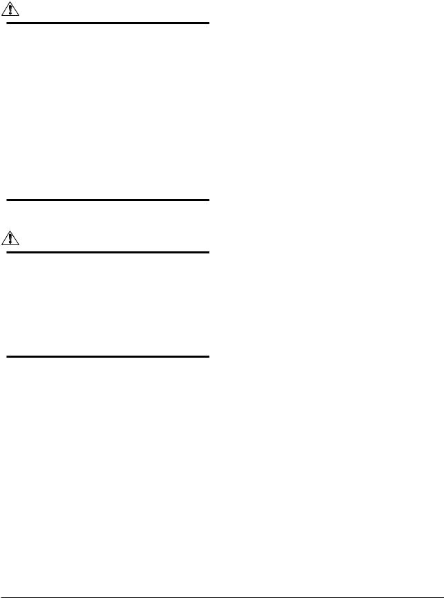
The ROTAMASS instrument measures the mass flow with the help of the so-called Coriolis force. This force occurs, when the medium being measured is flowing at velocity ν through a tube that is rotating around an axis perpendicular to the direction of flow at
angular velocity ϖ.
When the medium moves away from the axis of rotation it must be accelerated to an
increasingly high peripheral velocity. The force required for this is called Coriolis force, after its discoverer. The Coriolis force reduces the rotation. The opposite effect occurs, when the medium flows towards the axis of rotation. Then the Coriolis force amplifies the rotation.
The formula for the Coriolis force is as follows:
Fc = — 2 m (ϖ x ν )
x ν )
The entire measurement tube is deformed slightly by the Coriolis forces, in the way shown. This deformation is registered by movement sensors at points S1 and S2 .
For practical exploitation of this physical principle, it is sufficient for the tube to perform sympathetic oscillations on a small section of a circular path. This is achieved by exciting the measurement tube at point E by means of an electromagnetic exciter.
The general construction of a Coriolis mass flowmeter looks as followed:
|
All Rights Reserved. Copyright © 2003, Rota Yokogawa |
3-1 |
IM 01R04B04-00E-E 8th edition March 01, 2011 -00 |
3. Product description
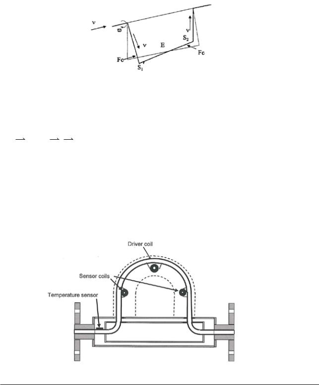
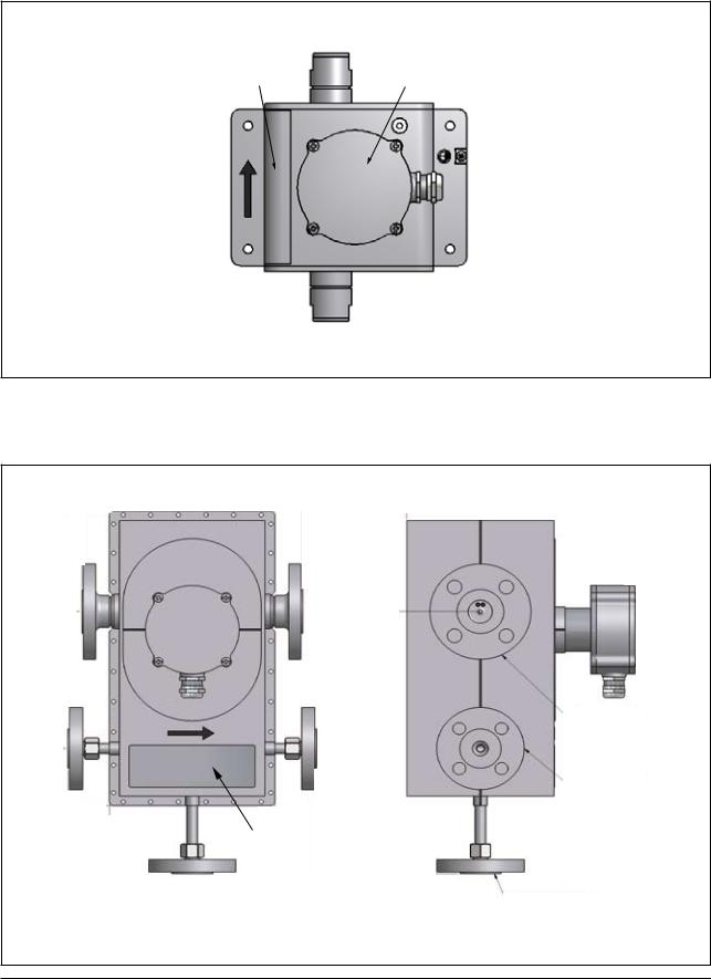
3.2 The Integral Type RCCT34 to 39/IR
The following drawing shows the general construction of the integral type ROTAMASS
|
Display |
Terminal box power and I/O |
Power supply cable entry
I/O — line cable entry
Name plate
Flow direction arrow
 Detector assembly
F31.EPS
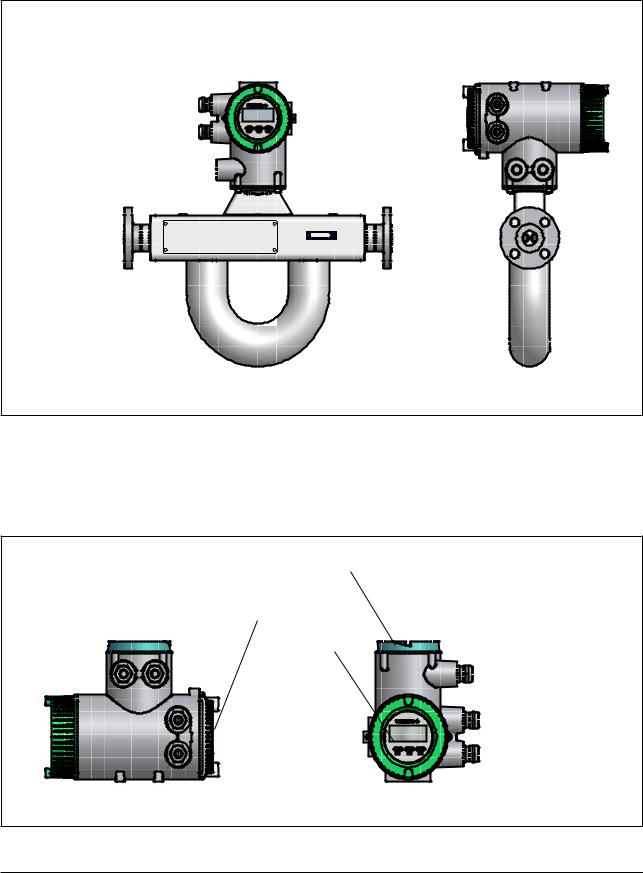
3.3 The Remote Field-Mount Converter RCCF31
The following drawing shows the general construction of the remote field-mount converter.
Terminal box detector connection
Terminal box power and I/O
Display
I/O cable entry
Power supply cable entry
F32.EPS
|
IM 01R04B04-00E-E 8th edition March 01, 2011 -00 |
3-2 |
All Rights Reserved. Copyright © 2003, Rota Yokogawa |
![]()
3. Product description
3.4 The Remote Rack-Mount Converter RCCR31
The following drawing shows the general construction of the remote rack-mount converter.
|
19-inch cassette |
Terminal board |
|||
|
Input / |
||||
|
Output |
||||
|
terminals |
||||
|
D+ |
||||
|
D- |
||||
|
S1+ |
||||
|
S1- |
||||
|
S2+ |
||||
|
S2- |
Iout1+ |
|||
|
TP1 |
||||
|
Iout1- |
||||
|
TP2 |
||||
|
Iout2+ |
||||
|
TP3 |
||||
|
Iout2- |
||||
|
COM |
||||
|
Pout+ |
||||
|
Pout- |
||||
|
Sin+ |
||||
|
Detector |
Sin- |
|||
|
Sout+ |
||||
|
Sout- |
||||
|
connection |
||||
|
L/+ |
||||
|
terminals |
||||
|
N/- |
||||
|
G |
||||
|
Display and infrared switches |
Ground |
|||
|
terminals |
||||
|
Power |
||||
|
terminals |
F35.EPS |
|
All Rights Reserved. Copyright © 2003, Rota Yokogawa |
3-3 |
IM 01R04B04-00E-E 8th edition March 01, 2011 -00 |
3. Product description
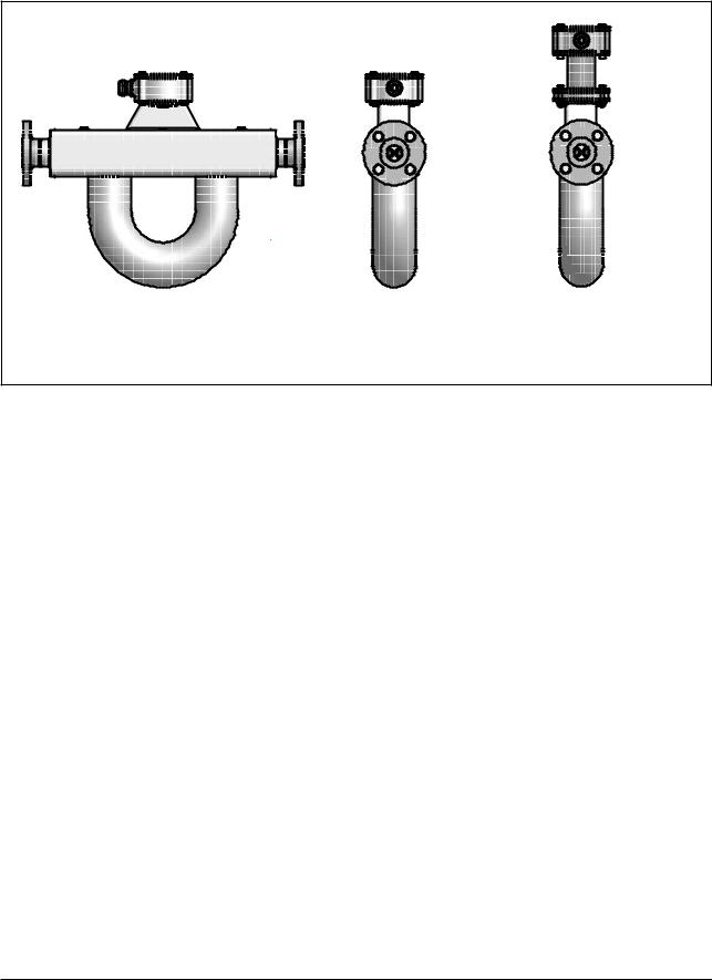
3.5 The Remote Detector RCCS30 to 33
The following drawing shows the general construction of the remote detector RCCS30 to 33.
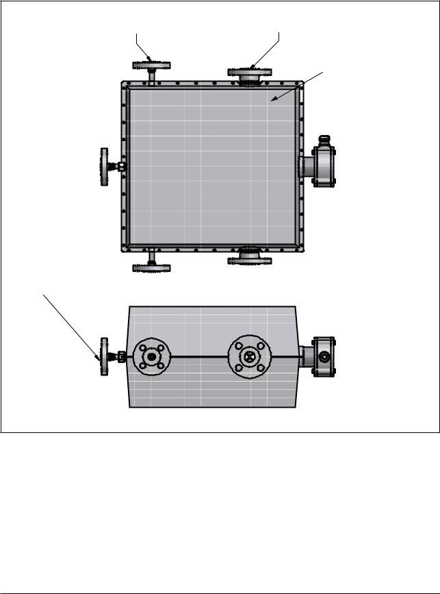
3.6 The Remote Detector RCCS30 to 33 /Tx
The following drawing shows the general construction of the remote detector RCCS30 to 33 /Tx.
see table 8
Factory insulation
Terminal box
Process connection
Heating connection
Name plate
Ventilation optional /T3
F37.EPS
Dimensions in mm
Weight (without process flanges): 12kg
|
IM 01R04B04-00E-E 8th edition March 01, 2011 -00 |
3-4 |
All Rights Reserved. Copyright © 2003, Rota Yokogawa |
3. Product description
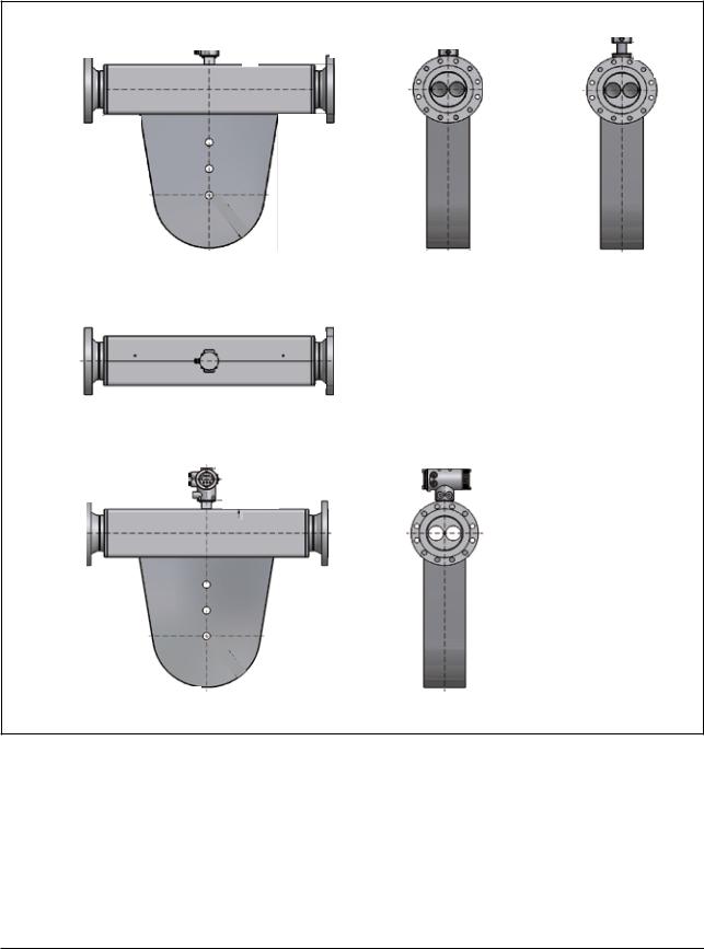
3.7 The Remote Detector RCCS34 to 39/IR
The following drawing shows the general construction of the remote detector RCCS34 to 39/IR.
Terminal box
Option /S2 and /MT
F34.EPS
|
All Rights Reserved. Copyright © 2003, Rota Yokogawa |
3-5 |
IM 01R04B04-00E-E 8th edition March 01, 2011 -00 |
3. Product description
3.8 The Remote Detector RCCS34 to 39/IR /Tx
The following drawing shows the general construction of the remote detector RCCS34 to 39/IR /Tx.
|
Heating connection |
Process connection |
|
optional /T2 or /T3 |
Factory insulation
Terminal box
Ventilation optional /T3
F36.EPS
|
IM 01R04B04-00E-E 8th edition March 01, 2011 -00 |
3-6 |
All Rights Reserved. Copyright © 2003, Rota Yokogawa |
3. Product description
3.9 The Remote and Integral Type RCCx39/XR
The following drawing shows the general construction of the RCCx39/XR.
Remote Type RCCS39/XR
Terminal box
Option /S2 and /MT
Integral Type RCCT39/XR
F38.EPS
|
All Rights Reserved. Copyright © 2003, Rota Yokogawa |
3-7 |
IM 01R04B04-00E-E 8th edition March 01, 2011 -00 |

3. Product description
3.10 Measurement system and applications
ROTAMASS measures the mass flow of fluids directly.
The measurement system uses the Coriolis principle and is suitable for a wide range of continuous flow measurement applications in all branches of process technology.
ROTAMASS has two components: the detector and the converter.
The detector measures the mass flow directly and converts it into electrical signals. The converter evaluates the electrical signals and outputs the following values:
—mass flow, independent from media properties, such as density, temperature, viscosity
—fluid density
—fluid temperature
The values are displayed and output as electrical values for use by other systems.
The converter is operated by three infra-red keys and a 4- line display and is standard equipped with HARTcommunication protocol.
ROTAMASS is suitable for
—measuring liquids, liquids with solid content, multi-phase mixtures
—measuring gases (restricted by density and pressure loss)
—simultaneous measurement of mass flow, density, temperature, volume flow and cumulated mass and volume
—measuring of concentrations of liquid mixtures, solutions and suspensions
—connection to controllers and process control systems
ROTAMASS provides the following I/O-connections and can be configured for a wide
variety of different measurement applications (controlling, checking, monitoring, metering, mixing, filling).
—2 active analog outputs
—2 passive pulse outputs / status outputs
—1 status input
optional /AP:
—1 active pulse output / status output
optional /NM:
—1 pulse output / status output according EN 50227 (NAMUR)
optional /KF2 :
—1 passive analog output Ex ia
—1 passive pulse output / status output Ex ia
These capabilities make ROTAMASS ideal for the increasing demand of requirements for automation and the growing trend towards batch processes.
optional /FB see IM 01R04B05-00E-E :
—1 Foundation Fieldbus communication line
optional /FB and /KF4 see IM 01R04B05-00E-E :
—1 intrinsic safe Ex ia Foundation Fieldbus communication line
|
IM 01R04B04-00E-E 8th edition March 01, 2011 -00 |
3-8 |
All Rights Reserved. Copyright © 2003, Rota Yokogawa |
3. Product description
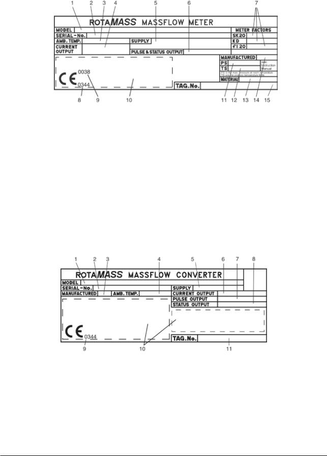
3.11 Name Plates
Name plate of Integral type RCCT3:
1 Model code
2Serial number
3Ambient temperature range
4 Current output range and load resistance range
5Power supply range
6 Maximum supply voltage and maximum current for passive pulseand statusoutput
7Calibration constants of detector (see also on calibration certificate)
8Number of notified body according ATEX (only for ATEX certified flowmeters)
9Number of notified body according PED (only for units with process connections more than DN25)
10Area for Exrelevant marking (see chapter 9). The CE-mark is not present for FM-approved units.
11PS = maximum permissible pressure
12TS = maximum permissible process temperature
13Material of metering tubes
14Year of manufacturing
15Customer specified tag number if option /BG was ordered
Name plate of Remote Converter RCCF31 / RCCR31:
1 Model code
2Serial number
3Year of manufacturing
4 Ambient temperature range
5Power supply range
6Current output range and load resistance range
7 Maximum supply voltage and maximum current for passive pulse output
8Maximum supply voltage and maximum current for passive status output
9Number of notified body according ATEX (only for ATEX certified flowmeters)
10Area for Exrelevant marking (see chapter 9). The CE-mark is not present for FM-approved units.
11Customer specified tag number if option /BG was ordered
|
All Rights Reserved. Copyright © 2003, Rota Yokogawa |
3-9 |
IM 01R04B04-00E-E 8th edition March 01, 2011 -00 |
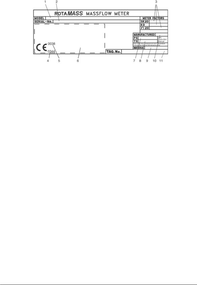
3. Product description
Name plate of Remote Detector RCCS3:
1 Model code
2Serial number
3Calibration constants of detector (see also on calibration certificate)
4Number of notified body according ATEX (only for ATEX certified flowmeters)
5 Number of notified body according PED (only for units with process connections greater than DN25) 6 Area for Exrelevant marking (see chapter 9). The CE-mark is not present for FM-approved units.
7PS = maximum permissible pressure
8 TS = maximum permissible process temperature
9 Material of metering tubes
10Year of manufacturing
11Customer specified tag number if option /BG was ordered
Name plate of RCCT3 and RCCS3 with option /DS (Dual Seal approval):
In general the name plates of these units are the same as shown above. The difference is as followed:
PS is named as «Working pressure range» TS is named as «Process temperature range»
«Dual Seal» is additionally stated on the name plate
|
IM 01R04B04-00E-E 8th edition March 01, 2011 -00 |
3-10 |
All Rights Reserved. Copyright © 2003, Rota Yokogawa |

4. INSTALLATION
4. Installation
4.1 General
WARNING
This instrument must be installed by an expert engineer or skilled personal. The procedures described in this chapter are not permitted for operators.
For the installation of explosion protected instruments see chapter 9 „Explosion protected type instruments”. If the detector is not insulated, the surface of detector may be very hot according to the process temperature.
IMPORTANT
—Keep protection sheet on the flanges attached until the flowmeter is installed to piping.
—Don’t open the terminal box until the wiring procedure. Leaving the box opened can result in insulation deterioration.
—A newly installed piping-line often contains foreign matters (such as welding scrap and wood chips). Remove them by flushing the piping before installing the flowmeter. This will help to prevent not only damaging the flowmeter, but making erroneous signal generated by foreign matters.
—For RCCT3 or RCCF31 at ambient temperature above 50°C a sunshade is recommended. This is particularly important in countries with high ambient temperatures.
About the site
To stabilize the instrument, please consider the following items where to place the instrument for your long-term use.
—Ambient Temperature
Please avoid installing in a place which has a large temperature gradient and variation as possible. And if the meter is subjected to radiant heat from plant, please use heat insulation measure or please set up so that is well ventilated.
—Atmospheric conditions
Please avoid to place in a corrosive atmosphere as possible. When used in corrosive atmosphere, allow better ventilation.
—Shock and vibration
Please install in a place without shock and vibration as possible.
—Explosion-proof equipment installations
If the product is installed in hazardous areas please notice the installation hints in chapter 9.
Sequence of installation:
—Mounting of detector RCCS30 to 33 on a 2-inch pipe if option /PD was ordered (see chapter 4.2)
—Piping of the detector or integral flowmeter in the line (see chapter 4.3)
—Customer insulation of detector if necessary (see chapter 4.4)
—Mounting of converter RCCF31 on a 2-inch pipe (see chapter 4.5)
—Mounting of converter RCCR31 in a subrack (see chapter 4.6)
—Alteration of converter display of converter RCCF31 if necessary (see chapter 4.7)
—Wiring of converter (see chapter 4.8)
—After installation an autozero according chapter 5.6 must be executed. When carrying out the zeroadjustment, the measuring tube should be filled with the liquid at “no flow”. It is therefore recommended to have shut-off valves at appropriate points of the upstream (vertical installation) and downstream (horizontal installation) of the flowmeter.
|
All Rights Reserved. Copyright © 2003, Rota Yokogawa |
4-1 |
IM 01R04B04-00E-E 8th edition March 01, 2011 -00 |
4. INSTALLATION
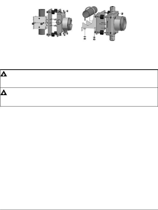
4.2 Mounting of detector RCCS30 to 33 option /PD
The detector RCCS30 to 33 can be mounted on a 2-inch pipe (option /PD) with a bracket and U-bolt assy.
4.3 Piping
IMPORTANT
When the following notes are not observed, flow measurements may not be correct and can damage the instrument. Please make correct piping design in accordance with the present guidelines.
IMPORTANT
Please be careful to install the flowmeter not too close to motors, transformers, inverters and other power
source, induction failure may occur.
1.The upstream and downstream piping length has no influence on the functioning of the instrument.
2.Piping requirements for proper operation :
•A Coriolis mass flowmeter can be installed vertically, horizontally or at any angle from the horizontal position.
•However, the piping must be installed to ensure that the measuring tube is always filled with liquid.
•The position of installation of the detector is arbitrary. A vertical mounting is recommended however.
|
IM 01R04B04-00E-E 8th edition March 01, 2011 -00 |
4-2 |
All Rights Reserved. Copyright © 2003, Rota Yokogawa |
![]()
4. INSTALLATION
Vertical installation (recommended):
Makes pipe easier to empty (in case of maintenance, startup, product change). Helps gas bubbles to escape.
Only one shut-off valve is required to ensure “no flow” for setting Autozero.
Horizontal installation :
For liquids: Measuring tube downwards so that no gas can collect if “no flow”.
For gasses: Measuring tube upwards so that no liquid can collect if “no flow”.
Installation at highest point of a piping system:
Avoid it, as this can lead to collection of gas bubbles.
Installation with pressure below 1 bar abs:
Avoid it, as suction can draw air into the measuring tube, leading to incorrect measurements. Free outlets to containers or vessels can generate low pressure by earth gravity acceleration.
|
Flow |
|
Flow |
|
Flow |
|
Flow |
|
F41.EPS |
•Do not stress the detector mechanically. Fix the pipe not on both ends of the detector but only at one side. Let the other side run free for minimum mechanical stress on the detector.
•Please use the standard reducers if the piping’s crosssection differs at the inlet or outlet point of the flowmeter.
Use shut-off valve and bypass line
To facilitate zero adjustment and maintenance, providing a bypass line is recommended.
|
Bypassvalve |
||
|
Shut-off |
Shut-off |
|
|
valve |
||
|
valve |
||
|
Coriolisflowmeter |
F0301.ai |
Supporting the Coriolis flowmeter
WARNING
—Please prevent the detector from pipeline stretching, vibration or shock.
—Please prevent the detector from direct fixing. (See figure below.)
—Please fix the pipe at first and support the detector with piping. (See figure below.)
—Please fix only one side of the detector instead of both sides so as to minimize mechanical stress to the detector.
|
All Rights Reserved. Copyright © 2003, Rota Yokogawa |
4-3 |
IM 01R04B04-00E-E 8th edition March 01, 2011 -00 |

4. INSTALLATION
|
pipe |
detector |
pipe |
pipe |
detector |
pipe |
||||||||||||||||||||||||
Please avoid direct fixing at detector. This causes measurement errors.
Please use the piping to support the detector.
In addition, to secure the support of only one side of the pipe detector.
F0302.ai
IMPORTANT
When density measurement is used and the instrument is set up horizontally, you will need to set a predetermined correction factor into the converter. Please see chapter 7.7.
Check the adjacent pipe
WARNING
Eccentricity and inclination are dangerous and may cause leakage in the piping. This may cause damage to the pipe flanges.
If the dimensions are not in tolerance or you have incline or eccentric pipes, please correct before installing detectors.
FDDFOUSJDJUZ

 JODMJOBUJPO
‘ BJ
If a new pipeline is provided, it may have other foreign materials such as wood chips and welding trash. Before installing, please remove them by flushing.
Mounting of integral and remote type detector
IMPORTANT
Please prepare your flange bolts and nuts. Please provide a gasket in the piping. However, if the gasket diameter is too large or too small.
(1) Mounting direction
Please note the flow direction according the arrow on the instrument. If flow is opposite to the direction of the arrow change parameter «Flow Direction» (see chapter 7.17).
(2) Mounting Flange
Install piping by using bolts, nuts and gaskets.
Bolts, nuts and gaskets are not included. Please prepare those according the flanges.
|
IM 01R04B04-00E-E 8th edition March 01, 2011 -00 |
4-4 |
All Rights Reserved. Copyright © 2003, Rota Yokogawa |

4. INSTALLATION
1JQF GMBOHF
(BTLFU
‘MPXNFUFS ‘MBOHF
/VU
(3) Mounting Clamp
Clamp and gasket must be mounted to fit into the groove of the ferrules of the pipe, fitted to cover the taper portion of the ferrule to the Coriolis flowmeter.
The ferrules, clamps, gaskets are not included and must be provided on site.
Clamp
Gasket


 Ferrule
F0306.ai
Gas flow measurement
CAUTION
A stable zero is mandatory for a good mass flow measurement. Mechanical installation stress and flow noise influence zero stability. Action has to be taken to avoid any generation of sound.
Recommendations:
•Support the weight of the detector by soft coupling (silicon or other kind of rubber support.
•Do not bend or stress the detector via the adjacent pipe. This is achieved by supporting the pipe 10D or more away from the detector.
•Pipe reduction or extension should be avoided directly before or after the meter.
•Avoid any control valves or orifices or any other sound generator near the detector.
|
All Rights Reserved. Copyright © 2003, Rota Yokogawa |
4-5 |
IM 01R04B04-00E-E 8th edition March 01, 2011 -00 |

4. INSTALLATION
4.4 Customer insulation
Customer insulation is only possible for remote detector RCCS3x with option /S2 (terminal box on distance). The upper line of the insulation must be minimum 40 mm below the terminal box.
IMPORTANT
For explosion proof types see tables «Temperature classification» in chapter 9.
4.5 Mounting of converter RCCF31 to 2-inch pipe
The field-mount converter RCCF31 can be mounted on a 2-inch pipe. Therefore use the delivered bracket and U-bolt assy.
F0309.ai
|
IM 01R04B04-00E-E 8th edition March 01, 2011 -00 |
4-6 |
All Rights Reserved. Copyright © 2003, Rota Yokogawa |

4. INSTALLATION
4.6 Mounting of converter RCCR31 in a subrack
If the remote rack mount converter RCCR31 was not ordered with option /SR1 or /SR2, the customer has to mount it to an own 19´´ subrack. The terminal board must be fixed by 6 screws (M2.5×10) to the rear side of the subrack.
The RCCR31 rack cassette must be inserted into the subrack.
4.7 Alteration of display (RCCT3 / RCCF31)
LCD display can be turned its direction with respect to piping configurations.
Removing four screws, adjusting display’s orientation and fixing the screws tightly again as shown in figure
|
below. |
Lock screw for cover (Ex d) |
F43.EPS
IMPORTANT
Fix the lock screw for use in hazardous area. After modification the user must ensure that the cover is screwed down tightly to maintain the IP rating of the housing, failure to do so may allow moisture ingress and failure of electronic components.
|
All Rights Reserved. Copyright © 2003, Rota Yokogawa |
4-7 |
IM 01R04B04-00E-E 8th edition March 01, 2011 -00 |

4. INSTALLATION
4.8Wiring
4.8.1General items
Notes concerning the wiring
When wiring, please observe the following precautions.
WARNING
—In order to prevent damage from condensation ensure isolation of the terminal box of the Coriolis flowmeter.
—Conduit wiring is recommended. Please use wiring conduit thick steel or flexible. In order to prevent rainwater from flowing or remain into the wiring pipe, please keep the watertight using a seal tape.
—Before opening the terminal box, be sure to turn off the power.
—Please fully tighten the terminal box cover.
—When removing the cover, please unlock the locking screw clockwise. (See figure below).
—After mounting the cover, please lock the cover by turning the locking screw counterclockwise. (See figure below).
—For explosion proof wiring please see chapter 9.
$PWFS MPDLJOH TDSFX
*OEJDBUPS 

 *OEJDBUPS
$PWFS MPDLJOH TDSFX
|
3$$5 *OUFHSBM UZQF |
3$$’ 3FNPUF UZQF DPOWFSUFS ‘ BJ |
|
IM 01R04B04-00E-E 8th edition March 01, 2011 -00 |
4-8 |
All Rights Reserved. Copyright © 2003, Rota Yokogawa |

4. INSTALLATION
Wiring port handling
(1) When waterproof property is unnecessary
For meters with NPT 1/2´´ threads the wiring port is sealed with a cap (not water-proof) that must be removed before wiring. For the unused wiring port, please prepare plug by the customer. For explosion proof, please refer to Chapter 9.
(BTLFU
1MBTUJD HMBOE
‘ BJ
(2) When waterproof property is necessary (Wiring using waterproof glands)
IMPORTANT
To prevent water or condensation from entering the converter housing, waterproof glands are recommended. Do not over-tighten the glands or damage to the cables may result. Tightness of the gland can be checked by confirming that the cable is held firmly in place.
(3) Conduit Wiring
When wiring the conduits, utilize the waterproof gland to prevent water from flowing into wiring connection port. Place the conduit pipe on an angle as shown in Figure below. Install a drain valve at the low end of the vertical pipe, and open the valve regularly.
%SBJO WBMWF
F0402.ai
|
All Rights Reserved. Copyright © 2003, Rota Yokogawa |
4-9 |
IM 01R04B04-00E-E 8th edition March 01, 2011 -00 |

4. INSTALLATION
4.8.2 Ground (earth) connections
IMPORTANT
Grounding resistance of 10 Ω or less is necessary. For explosion proof type follow the domestic electrical requirements as regulated in each country.
The following table shows the grounding:
|
*OUFHSBM UZQF |
3FNPUF UZQF |
r 1SPUFDUJWF FBSUI UFSNJOBM DPOOFDUFE BT CFMPX r %FUFDUPS DPOOFDUFE UP DPOWFSUFS WJB SFNPUF DBCMF r 1SPUFDUJWF FBSUI UFSNJOBM DPOOFDUFE BT CFMPX
|
1SPUFDUJWF FBSUI |
1SPUFDUJWF FBSUI |
|
%FUFDUPS |
3FNPUF DBCMF |
|
%FUFDUPS |
|
(SPVOEJOH SFTJTUBODF 0IN PS MFTT |
(SPVOEJOH SFTJTUBODF |
|
|
0IN PS MFTT |
||
|
‘ BJ |
—The location of the protective earth terminal is at the terminal box of converter as shown in figure below.
—In case of remote type, the detector is grounded at the converter. (See figure above.)
—Use insulated PVC wire for 600 V for grounding wire.
DPWFS MPDLJOH TDSFX
EJTQMBZ 

 EJTQMBZ
QSPUFDUJWF FBSUI
UFSNJOBM MPDBUJPO
DPWFS MPDLJOH TDSFX
|
3$$5 JOUFHSBM UZQF |
3$$’ SFNPUF DPOWFSUFS |
‘ BJ


 1SPUFDUJWF FBSUI UFSNJOBM . TDSFX
‘ BJ
|
IM 01R04B04-00E-E 8th edition March 01, 2011 -00 |
4-10 |
All Rights Reserved. Copyright © 2003, Rota Yokogawa |

4. INSTALLATION
4.8.3 Wiring technique
Cable connection on terminal block:
For connecting the cables to power-, I/O- and remote cable connection terminals a special tool is attached to the instrument. The terminal looks as follows:
$BCMF DPOOFDUJPO QPSU
|
8JSJOH UPPM TMPU |
|||
|
$BCMF |
|||
|
PP |
$BCMF DPOOFDUJPO |
8JSJOH UPPM TMPU |
|
|
D+ |
|||
|
D– |
QPSU |
S1+
S1–
S2+
S2–
TP1
TP2
TP3
COM
YOKOGAWA
‘ BJ
Insert the auxiliary tool from the top into the terminal block.
‘ BJ
Tilt the tool until it opens the cable port and insert the cable. Tilt the tool back and the opening is closed and the cable is fixed. Remove the tool. Fix the wires one at a time, please make sure that is secured to the wiring terminal block.
‘ BJ
IMPORTANT
— Do external electrical connection in conformity with EN 61010-1 or equivalent national regulations. For hazardous area installation in Europe (ATEX) use standard EN 60079-14 as a guideline.
— Do not switch power supply on before all wiring is finished.
|
All Rights Reserved. Copyright © 2003, Rota Yokogawa |
4-11 |
IM 01R04B04-00E-E 8th edition March 01, 2011 -00 |

4. INSTALLATION
4.8.4 Assembling and connecting the Remote Cable RCCY03
Remote type converter RCCF31 / RCCR31 are used with remote type detector RCCS3. To connect these instruments use pair- / triple-twisted cable with overall shielding type Li2Y(st)+CY 3x2AWG24 + 1×3 AWG20 exclusive cable RCCY03. The maximum length is 300 m / 984 ft; 50 m/164 ft for FM-applications Cross-sectional view of remote cable RCCY03:
1MBTUJD TIFBU 0VUFS TIJFME
8SBQ
|
«MVNJOJVNGPJM |
||
|
$PSF |
||
|
‘JMMFS |
||
|
*OOFSTIJFME |
‘ BJ |
|
|
For RCCY03 -1-L |
the cable is completely terminated. |
|
|
For RCCY03 -0-L |
the termination set is attached and the customer has to terminate the cable by his own. |
The termination set contains:
|
— 6 x 20 mm 0.15 m shrink down plastic tube, d= 3.2 mm |
||||||||||
|
— |
2 x 20 mm 0.05 m shrink down plastic tube, d= 4.8 mm |
|||||||||
|
— |
18 conductor markers |
|||||||||
— 12 terminal sleeves 0.25 mm2 light blue
— 6 terminal sleeves 0.5 mm2 orange
— 1 terminal sleeve 1.5 mm2
‘ BJ
For ATEX explosion proof application cable RCCY03-xLxxx /KS1 (blue color) is recommended.
NOTE
Careful assembly of the cable is indispensable for correct connection between the detector and the converter. This ensures good measuring results.
|
IM 01R04B04-00E-E 8th edition March 01, 2011 -00 |
4-12 |
All Rights Reserved. Copyright © 2003, Rota Yokogawa |
![]()
4. INSTALLATION
Termination procedure:
Cable end detector
—Remove PVC outer sheeting and outer shielding 100 mm from the end.
—Remove the clear wrap and the filler material.
—Remove the foil that is around the isolated wires.
—Clip off each drain wire close to the cable jacket.
—Slide a shrink down plastic tube (d = 3.2 mm, l = 20 mm) over each of the 3 pairs and a shrink down plastic tube (d = 4.8 mm, l = 20 mm) over the triple of wires, push it to the cable jacket and heat with hot air.
—Strip 8 mm of the cable ends.
—Fix the light blue terminal sleeves (0.25 mm2) to the wire endings of the 3 cable pairs.
—Fix the orange terminal sleeves (0.5 mm2) to the wire endings of the cable triple
—Make a radial cut into the PVC outer sheeting 25 mm from the end and cut lenghtwise.
Rotamass Remote Cable RCCY03 : Detector RCCS side
|
1 |
|||
|
2 |
|||
|
Terminal sleeves |
3 |
||
|
0.25mm (light blue) |
|||
|
Shrinkdown |
4 |
||
|
Cut |
plastic tube |
||
|
d 3.2mm |
5 |
||
|
6 |
|
25 |
|
Shrinkdown |
|
plastic tube |
|
d 5mm |
7
8
 9
9
Terminal sleeves 0.5mm (orange)
Cable end converter
—Remove PVC outer sheeting and outer shielding 100 mm from the end.
—Remove the clear wrap and the filler material.
—Remove the foil that is around the isolated wires.
—Do not clip off the drain wires !
—Twist the 4 drain wires together and fix the 1.5 mm2 terminal sleeve.
—Slide a shrink-down plastic tube (d = 3.2 mm, l =20 mm) over each of the 3 pairs and a shrink down plastic tube (d = 4.8 mm, l = 20 mm) over the triple of wires, push it to the cable jacket and heat with hot air.
—Strip 8 mm of the cable ends.
—Fix the light blue terminal sleeves (0.25 mm2) to the wire endings of the 3 cable pairs.
—Fix the orange terminal sleeves (0.5 mm2) to the wire endings of the cable triple
—Make a radial cut into the PVC outer sheeting 25 mm from the end and cut lenghtwise.
—Slide the conductor markers onto the pairs of wires on both sides of the cable, so that the pairs are numbered 1-2, 3-4, 5-6 and the triple 7-8-9. Each cable must have the same number on detector and on
converter side.
Rotamass Remote Cable RCCY03 : Converter RCCF31 side
|
1 |
||
|
2 |
||
|
3 |
||
|
Cut |
Shrinkdown |
4 |
|
plastic tube |
||
|
d 3.2mm |
5 |
|
|
6 |
|
7 |
|
|
7 |
|
|
8 |
|
|
25 |
9 |
|
Shrinkdown |
9 |
|
plastic tube |
|
|
d = 5mm |
|
All Rights Reserved. Copyright © 2003, Rota Yokogawa |
4-13 |
IM 01R04B04-00E-E 8th edition March 01, 2011 -00 |

4. INSTALLATION
Cable connection to detector RCCS3 and field-mount converter RCCF31: 1. Remove connection box cover detector and converter (see figure below).
‘ BJ
2.Loosen the thread of cable gland and insert the cable into the cap and the clamp part. (See figure below.)
3.Remove the PVC outer sheathing 25 mm from the end and fold back outer shield over the clamp part.
(See figure below.)
|
$BQ |
8JSJOH QPSU |
|||||||||||||||||||
|
$MBNQ QBSU |
||||||||||||||||||||
|
$BCMF |
||||||||||||||||||||
|
$BCMF HMBOE |
0VUFS TIJFME |
4DSFX QBSU |
|
|
PG DBCMF |
‘ BJ |
4.Tighten the cable gland.
5.Connect the numbered leads to the terminals as shown in the figure below.
6.Connect inner shields to terminal COM.
|
3$$4 |
3$$: |
3$$’ |
||||
|
% |
% |
|||||
|
% |
% |
|||||
|
3FNPUF EFUFDUPS 3$$4 |
4 |
4 |
3FNPUF $POWFSUFS 3$$’ |
|||
|
4 |
4 |
|||||
|
UFSNJOBM |
4 |
4 |
UFSNJOBM |
||
|
4 |
4 |
||||
|
51 |
51 |
||||
|
51 |
51 |
||||
|
51 |
51 |
||||
|
% |
*OOFS TIJFMET |
$0. |
% |
||
|
% |
% |
||||
|
4 |
|||||
|
4 |
|||||
|
4 |
|||||
|
4 |
|||||
|
4 |
|||||
|
4 |
|||||
|
4 |
|||||
|
4 |
|||||
|
51 |
|||||
|
51 |
|||||
|
51 |
|||||
|
51 |
|||||
|
51 |
|||||
|
51 |
|||||
|
$0. |
|||||
‘ BJ
7. Close the connection box covers.
|
IM 01R04B04-00E-E 8th edition March 01, 2011 -00 |
4-14 |
All Rights Reserved. Copyright © 2003, Rota Yokogawa |

4. INSTALLATION
Cable connection to rack-mount converter RCCR31:
1.Loose the cable clamp on terminal board
2.Remove the 25 mm section of PVC outer sheathing from the cable and fix the outer ring of the cable with the cable clamp on terminal board. (see left figure below).
3.Connect the numbered leads to the terminals as shown in the right figure below.
4.Connect inner shields to terminal COM.
|
Detector |
Cable |
Converter |
|||||||||||
|
RCCS3 |
RCCY03 |
RCCR31 |
|||||||||||
|
D+ |
1 |
1 |
D+ |
||||||||||
|
D- |
2 |
2 |
D- |
||||||||||
|
S1+ |
3 |
3 |
S1+ |
||||||||||
|
S1- |
4 |
4 |
S1- |
||||||||||
|
S2+ |
5 |
5 |
S2+ |
||||||||||
|
S2- |
6 |
6 |
S2- |
||||||||||
|
TP1 |
7 |
7 |
TP1 |
||||||||||
|
TP2 |
8 |
8 |
TP2 |
||||||||||
|
TP3 |
9 |
9 |
TP3 |
||||||||||
|
Shields |
COM |
||||||||||||
4.8.5 Power supply wiring
The terminals for the power supply and for the I/O ports are in a separate terminal box as shown in the figures below.
$PWFS MPDLJOH TDSFXT
%JTQMBZ
 %JTQMBZ
$PWFS MPDLJOH TDSFXT
|
3$$5 *OUFHSBM UZQF |
3$$’ SFNPUF DPOWFSUFS |
‘ BJ |
1PXFS UFSNJOBM CMPDL
1SPUFDUJWF FBSUI
*OQVU 0VUQVU TJHOBM 


 UFSNJOBM . TDSFX UFSNJOBM CMPDL
‘ BJ
|
All Rights Reserved. Copyright © 2003, Rota Yokogawa |
4-15 |
IM 01R04B04-00E-E 8th edition March 01, 2011 -00 |

4. INSTALLATION
CAUTION
1.Before starting the wiring, turn off the source of the supply power and check with the tester that there is no voltage at the cable.
2. For RCCT3 / RCCF31 the protective ground conductor must be connected to the separate PE terminal in the terminal box with Crimp-on ring-type terminal in order to avoid personal shock hazard.
2.For RCCR31 the protective ground conductor must be connected to the separate PE terminal on the terminal board in order to avoid personal shock hazard.
3.An exclusive external circuit breaker must be placed near each flowmeter.
4.Check the external circuit breaker’s rating conforms to the requirements specified in the specification of this instrument.
5.Wire the power supply cable keeping the distance of 1 cm or more from other signal wires.
6.Confirm the operating voltage of the converter before operation.
7.Please lock the cover of the converter with hexagon lock screw before operation (only RCCT3 /RCCF31)
•Connect the power supply cable to the terminals inside of the converter terminal box (RCCT3 /RCCF31) or on terminal board (RCCR31).
•Confirm two ferrite core sets are attached to the flowmeter.
•Insert the cables into ferrite core before connecting to the terminals. Fix the ferrite core to the cable with clamping wire.
•Connect the power cables to the terminals according to the figure below.
•For the connection of protective ground conductor to PE terminal of RCCF31 / RCCT3 use a crimp-on ring type terminal. For RCCR31 connect the protective ground conductor to PE terminal of terminal board.
|
IM 01R04B04-00E-E 8th edition March 01, 2011 -00 |
4-16 |
All Rights Reserved. Copyright © 2003, Rota Yokogawa |

+ — 20.5 to 28.8 V DC
4. INSTALLATION
CAUTION
Special connections for Ex version :
The converter case must be connected to the potential equalisation facility of the
hazardous area , e.g. to the U-clamp PA terminal on the outside at the converter. Please refer to chapter 9 “Explosion Protected Type Instruments”.
Power supply cable
Cable : Use cables acc. to VDE 0250, VDE 0281 or equivalents.
Outer diameter : DIN and NPT cable gland: 6.5 to 10.5 mm in diameter
|
Nominal cross section of conductive wire |
: 0.5 to 2.5 mm² |
|
Outer diameter of cores insulation part |
: < 3.6 mm |
|
Connecting length of conductive wire part |
: < 9 mm |
24V DC connections
For the DC power supply type, connect a 24 V DC power supply, following the precautions below.
1. Connecting Power Supply
Please refer to the Figure in right. AC power supplies
can not be connected. Confirm the polarity of DC power supply.
F49.EPS
2. Supply voltage rating
The specification for the supply voltage is 20.5 – 28.8 V DC. But because the input voltage of the converter drops due to cable resistance, it should be used within the following range.
3. Ground connection
Connect ground as shown on page 4-8 due to EMC protection.
Allowed cable length m (ft)
|
1000 |
||||||
|
(3300) |
||||||
|
900 |
||||||
|
(2970) |
||||||
|
800 |
||||||
|
(2640) |
||||||
|
700 |
||||||
|
(2310) |
||||||
|
600 |
||||||
|
(1980) |
||||||
|
500 |
||||||
|
(1650) |
||||||
|
400 |
||||||
|
(1320) |
||||||
|
300 |
||||||
|
(990) |
||||||
|
200 |
||||||
|
(660) |
||||||
|
100 |
||||||
|
(330) |
||||||
|
0 |
voltage V |
|||||
|
20 |
22 |
24 |
26 |
28 |
30 |
|
|
Cable crosssection area 2mm |
|
Cable crosssection area 1.25mm |
F410.EPS |
|
All Rights Reserved. Copyright © 2003, Rota Yokogawa |
4-17 |
IM 01R04B04-00E-E 8th edition March 01, 2011 -00 |

4. INSTALLATION
4.8.6 Connecting to external instruments
•Use cables with cross section 0.08 to 0.5 mm²
•Connect the cables from the external instruments to the terminals inside of the converter terminal box (RCCT3 / RCCF31 or on terminal board (RCCR31).
•Confirm two ferrite core sets are attached to the flowmeter.
•Insert the cable into ferrite core before connecting to the terminals. Fix the ferrite core (see figure on page 4-16)
•Connect the cables to the terminals according to the figure below.
I/O-Terminal Overview :
1.Analog signal output (Iout 1 and Iout 2) ROTAMASS has 2 analog outputs, 4 to 20 mA DC.
Load resistance 20600 Ω (/KF2 has only one analog output, which is intrinsic safe. See chapter 4.8.8).
|
+ |
Iout + |
|
ROTAMASS |
Receiving instrument |
|
— |
— |
|
Iout — |
|
|
Load resistance max. 600 Ω |
|
|
F411.EPS |
|
IM 01R04B04-00E-E 8th edition March 01, 2011 -00 |
4-18 |
All Rights Reserved. Copyright © 2003, Rota Yokogawa |

4. INSTALLATION
2.Pulse Output passive (Pout / Sout)
ROTAMASS has 2 pulse outputs (isolated transistor contact).
Attention must be paid to voltage and polarity when wiring (/KF2 has one passive pulse output, which is intrinsic safe. See chapter 4.8.8)
|
Protective diode |
||
|
ROTAMASS |
Pout +/Sout + |
|
|
Pulse output |
Mechanical counter |
|
|
Pout — / |
||
|
Sout- |
30VDC, 200mA max |
|
|
ROTAMASS |
Pout + /Sout + |
|
|
Pulse output |
Load |
Electronic counter |
|
Pout — / |
||
|
Sout- |
F412.EPS |
3.Status Output passive (Pout / Sout)
The pulse outputs can be set to status outputs by menu item. Since this is an isolated
transistor contact, attention must be paid to voltage and polarity when wiring. This output cannot switch an AC load. To switch an AC load, an intermediate relay (see the figure below) is required.
|
Protective diode |
||
|
ROTAMASS |
Pout + /Sout + |
|
|
Load |
||
|
Pout — / |
||
|
Sout- |
30VDC, 200mA max |
|
|
ROTAMASS |
Pout + /Sout + |
|
|
Magnetic |
||
|
valve |
||
|
Pout — / |
||
|
Sout- |
F413.EPS |
|
|
All Rights Reserved. Copyright © 2003, Rota Yokogawa |
4-19 |
IM 01R04B04-00E-E 8th edition March 01, 2011 -00 |

4. INSTALLATION
4.Pulse Output active (option /AP)
Pulse output 1 (Pout) can be ordered as active output. Not possible with intrinsic safe outputs option /KF2.
|
305″.»44 |
7 |
||||||
|
1VMTF SBUF )[ L)[ |
|||||||
|
Lų |
|||||||
|
1PVU |
*G UIF MPBE SFTJTUBODF JT Lų |
||||||
|
7 7 WPMUBHF QVMTF JT PCUBJOFE |
|||||||
|
-PBE |
&MFDUSPOJD DPVOUFS |
||||||
|
1PVU |
‘ BJ |
||||||
5.Status Output active (option /AP)
Status output 1 (Pout) can be ordered as active output. Not possible with intrinsic safe outputs option /KF2.
+
ROTAMASS
12V, 6mA max., Load > 10kΩ
Pout +
Load
Pout —
ROTAMASS +
12V, 6mA max. Pout +
Magnetic valve
Pout —
F421.EPS
|
IM 01R04B04-00E-E 8th edition March 01, 2011 -00 |
4-20 |
All Rights Reserved. Copyright © 2003, Rota Yokogawa |

4. INSTALLATION
6.Pulse / Status Output according EN 60947-5-6 (NAMUR) (option /NM) Pulse output 1 (Pout) can be ordered as NAMUR output.
|
Transmitter Relay |
||
|
~ |
~ |
|
|
ROTAMASS |
Pout + |
|
|
1k |
U |
|
|
10k |
+ |
|
|
Pulse output |
— |
|
|
Pout — |
F426.EPS
7.Status input (Sin)
Status input is designed for use with voltage-free (“dry”) contact (activate source current to detect the contact state). Be careful not to connect to any signal source carrying any voltage. Applying voltage may damage the input circuit.
Close: 200Ω max
Open: 100kΩ min
|
Sin- |
Voltage-free |
|
|
contact input |
F415.EPS |
|
All Rights Reserved. Copyright © 2003, Rota Yokogawa |
4-21 |
IM 01R04B04-00E-E 8th edition March 01, 2011 -00 |

4. INSTALLATION
4.8.7 Connecting HARTCommunication
HART communication is available on analog output 1 and the HART-communicator is connected via load resistance (230 … 600 Ω) as shown on the figure below.
Control room
4 to 20mA DC signal trans-
Intermediate mission line Terminal board terminals
Receiving instrument
ROTAMASS
|
HART |
HART |
HART |
|
|
Communicator |
Communicator |
Communicator |
F417.EPS |
4.8.8 Flowmeters with intrinsic safe outputs
ROTAMASS with option /KF2 has one intrinsic safe current output and one intrinsic safe pulse / status output. The Ex-data of this output can be found in chapter 9.1.
The second current output, the second pulse / status output and the status input are not available. The concerning parameters in the menu are not visible.
Current output : The intrinsic safe current output is passive and an external power supply with shunt-diode type barrier or isolation type barrier should be connected.
Example of installation :
|
Hazardous area |
Safe area |
||
|
ROTAMASS |
Vin |
||
|
/KF2 |
Iout + |
||
|
R barrier |
|||
|
Iout — |
V out |
||
|
4-20mA |
R load |
||
|
Ground |
|||
|
F418.EPS |
|
IM 01R04B04-00E-E 8th edition March 01, 2011 -00 |
4-22 |
All Rights Reserved. Copyright © 2003, Rota Yokogawa |