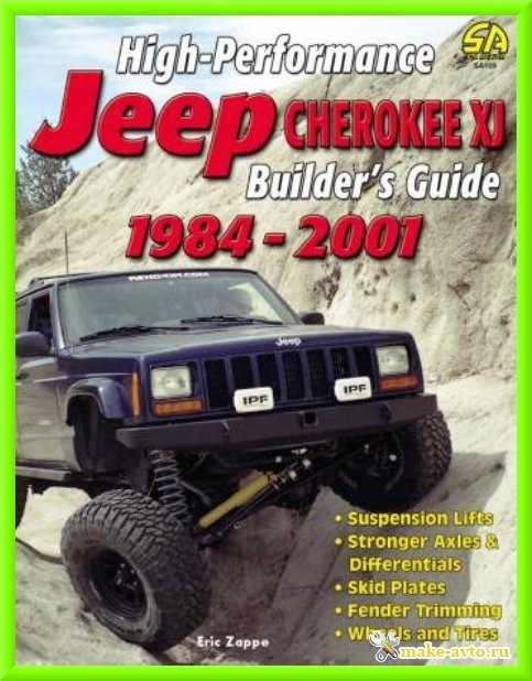
Подборка руководств на английском языке по техническому обслуживанию и ремонту автомобиля Jeep Cherokee в кузове XJ 1988-2001 годов выпуска.
- Автор: —
- Издательство: Chrysler International
- Год издания: 1988-2001
- Страниц: —
- Формат: PDF
- Размер: 311,0 Mb
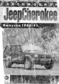
Руководство по ремонту автомобиля Jeep Cherokee 1984-1991 годов выпуска.
- Автор: —
- Издательство: —
- Год издания: 1995
- Страниц: 145
- Формат: PDF
- Размер: 46,7 Mb
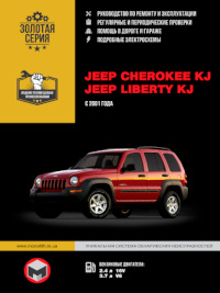
Руководство по эксплуатации и ремонту автомобилей Jeep Cherokee и Jeep Liberty с 2001 года выпуска с бензиновыми двигателями объемом 2,4/3,7 л.
- Автор: —
- Издательство: Монолит
- Год издания: —
- Страниц: 328
- Формат: —
- Размер: —

Руководство по эксплуатации и техническому обслуживанию автомобиля Jeep Cherokee 2014 года выпуска.
- Автор: —
- Издательство: Chrysler International
- Год издания: 2013
- Страниц: 412
- Формат: PDF
- Размер: 5,7 Mb

Недавно разобрался на компьютере в куче документов на чирка. Всё лишнее отсеял, оставил для себя только файлы с описанием машин до 91-го года. Залил на Яндекс.Диск. Может кому-то пригодится.
1. Самый полезный мануал по ремонту (1984-1990гг). Всё на русском. Такая же книжка валяется в машине, уже не раз выручала — Скачать
2. Аналогичная инструкция по ремонту, но немного отличается от предыдущей. Много полезного, но качество фоток так себе. И непонятно на какие года, но точно до 93-го года. Тоже на русском — Скачать
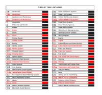
3. Удобный каталог с номерами запчастей (1987-1990гг). Слева в менюшке всё расписано по категориям. Правда на английском. Но по картинкам в принципе всё понятно — Скачать
4. Каталог запчастей (с номерами) фирмы Crown на вагонир, команч и чирок до 90-го года. Ни разу толком не пользовался. Но пусть будет на всякий случай  — Скачать
5. Главный интернет каталог — Elcats.ru. Нажимая кнопку «цена» автоматически переводит вас на сайт Exist.ru.
Ещё совет тем, кто ездит далеко и надолго с ноутбуком — скачайте себе всю Энциклопедию Jeep на комп. Весит немного, но при поломке вдалеке от дома может пригодится. Скачать можно любым оффлайн-браузером. Например Teleport Pro
Если у кого есть что-нибудь полезное по теме — кидайте ссылки в комменты, добавлю в пост.
инструкцияJeep Cherokee (2017)

Cherokee
ơƦƭƧƩƥƙƯơƸƨƧƶƣƪƨƤƬƙƫƙƯơơ
Посмотреть инструкция для Jeep Cherokee (2017) бесплатно. Руководство относится к категории Автомобили, 4 человек(а) дали ему среднюю оценку 8.5. Руководство доступно на следующих языках: русский. У вас есть вопрос о Jeep Cherokee (2017) или вам нужна помощь? Задайте свой вопрос здесь
Главная
Не можете найти ответ на свой вопрос в руководстве? Вы можете найти ответ на свой вопрос ниже, в разделе часто задаваемых вопросов о Jeep Cherokee (2017).
Как перевести мили в километры?
Где я могу узнать идентификационный номер транспортного средства Jeep?
Что такое идентификационный номер транспортного средства (VIN)?
Когда транспортному средству Jeep требуется техническое обслуживание?
Когда следует заменять тормозную жидкость на Jeep?
В чем разница между топливом E10 и E5?
Одна или несколько дверей не открываются изнутри. Что мне делать?
Автомобильный радиоприемник не включается, что делать?
Инструкция Jeep Cherokee (2017) доступно в русский?
Не нашли свой вопрос? Задайте свой вопрос здесь
Искать в
-
Везде
-
Файлы
-
Ещё…
Поиск контента, содержащего…
-
Любое слово запроса
-
Все слова запроса
Поиск результатов в…
-
Заголовки и содержание контента
-
Только заголовки контента
- Manuals
- Brands
- Jeep Manuals
- Automobile
- GRAND CHEROKEE 2021
- Owner’s manual
-
Contents
-
Table of Contents
-
Bookmarks
Quick Links
202 1 CH ER OKEE
OWN ER’S MA N UA L
Related Manuals for Jeep CHEROKEE 2021
Summary of Contents for Jeep CHEROKEE 2021
-
Page 1
202 1 CH ER OKEE OWN ER’S MA N UA L… -
Page 2
This Owner’s Manual illustrates and describes the operation of features and equipment that are either standard or optional on this vehicle. This manual may also include a description of features and equipment that are no longer available or were not ordered on this vehicle. -
Page 3: Table Of Contents
TABLE OF CONTENTS INTRODUCTION ……………………..8 GETTING TO KNOW YOUR VEHICLE …………….. 14 GETTING TO KNOW YOUR INSTRUMENT PANEL …………85 STARTING AND OPERATING ………………..108 MULTIMEDIA ……………………..180 SAFETY ……………………….262 IN CASE OF EMERGENCY ………………..327 SERVICING AND MAINTENANCE ………………363 TECHNICAL SPECIFICATIONS ………………..
-
Page 4
INTRODUCTION STEERING WHEEL……….40 VEHICLE SECURITY SYSTEM — IF EQUIPPED..23 To Arm The System ……..23 Tilt/Telescoping Steering Column ….40 Symbols Key…………9 To Disarm The System ……. 24 Heated Steering Wheel — If Equipped ..41 ROLLOVER WARNING ……….. 9 Rearming Of The System…… -
Page 5
INTERIOR STORAGE AND EQUIPMENT….79 Turn Signals ……….49 POWER SUNROOF WITH POWER SHADE — IF Lane Change Assist — If Equipped ….. 49 EQUIPPED …………68 Storage…………79 Battery Saver……….49 Sun Visors ……….. 81 Opening And Closing The Sunroof ….68 INTERIOR LIGHTS ……….49 AUX/USB Control —… -
Page 6
PARKSENSE FRONT/REAR PARK ASSIST ONBOARD DIAGNOSTIC SYSTEM — OBD II … 106 FOUR-WHEEL DRIVE OPERATION ….120 Onboard Diagnostic System 1-Speed Four-Wheel Drive (4WD) — If SYSTEM — IF EQUIPPED ……..141 (OBD II) Cybersecurity……..106 Equipped …………120 ParkSense Sensors ……..142 EMISSIONS INSPECTION AND MAINTENANCE 2-Speed Four-Wheel Drive ParkSense Display…….. -
Page 7
TRAILER TOWING ……….163 UCONNECT INTRODUCTION ……196 CONNECTED SERVICES FAQs ……252 Common Towing Definitions …..164 System Overview ……..196 Connected Services SOS FAQs ….252 Trailer Hitch Classification ……166 Drag & Drop Menu Bar……198 Connected Services Remote Door Trailer Towing Weights (Maximum Trailer Safety And General Information ….198 Lock/Unlock FAQs …….. -
Page 8
SAFETY IN CASE OF EMERGENCY TOWING A DISABLED VEHICLE……357 Front-Wheel Drive (FWD) Models …..358 SAFETY FEATURES ……….262 HAZARD WARNING FLASHERS……327 4×4 Models With 1–Speed Power Anti-Lock Brake System (ABS) ….262 ASSIST AND SOS MIRROR — IF EQUIPPED …327 Transfer Unit ……….359 Anti-Lock Brake (ABS) Warning Light..263 FUSES …………..331… -
Page 9
CUSTOMER ASSISTANCE DEALER SERVICE ……….371 INTERIORS …………409 Engine Oil ……….372 Seats And Fabric Parts ……409 SUGGESTIONS FOR OBTAINING SERVICE FOR Engine Oil Filter……….372 Plastic And Coated Parts……409 YOUR VEHICLE ……….420 Engine Air Cleaner Filter ……373 Leather Surfaces ……..410 Prepare For The Appointment …. -
Page 10: Introduction
For this reason, it reserves the right to make changes to the model described for technical and/or commercial reasons. For further information, contact an authorized dealer. When it comes to service, remember that authorized dealers know your JEEP® best, have factory-trained technicians and genuine MOPAR® parts, and care about your satisfaction.
-
Page 11: Symbols Key
SYMBOLS KEY ROLLOVER WARNING Utility vehicles have a significantly higher rollover rate than other types of Indicates a potentially hazardous situation, vehicles. This vehicle has a higher ground clearance and a higher center of WARNING! which if not avoided, could result in death or gravity than many passenger vehicles.
-
Page 12: Warnings And Cautions
SYMBOL GLOSSARY Failure to use the driver and passenger seat belts provided is a major cause of severe or fatal injury. In fact, the US government notes that Some car components have colored labels with symbols indicating the universal use of existing seat belts could cut the highway death toll by precautions to be observed when using this component.
-
Page 13
Yellow Warning Lights Red Warning Lights Adaptive Cruise Control (ACC) Fault Warning Electronic Throttle Control (ETC) Warning Light Light — If Equipped Ú page 98 Ú page 100 Engine Coolant Temperature Warning Light Electronic Park Brake Warning Light Ú page 99 Ú… -
Page 14
Yellow Indicator Lights Yellow Warning Lights Active Speed Limiter Fault Indicator LaneSense Warning Light — If Equipped Light — If Equipped Ú page 101 Ú page 104 Engine Check/Malfunction Indicator Warning Forward Collision Warning (FCW) Off Indicator Light (MIL) Light — If Equipped Ú… -
Page 15
Green Indicator Lights White Indicator Lights Adaptive Cruise Control (ACC) Ready Light — If Cruise Control Set Indicator Light — If Equipped Equipped Ú page 104 Ú page 105 Adaptive Cruise Control (ACC) Set Light — If Front Fog Indicator Light — If Equipped Equipped Ú… -
Page 16: Getting To Know Your Vehicle
GETTING TO KNOW YOUR VEHICLE KEYS 1 — PANIC Button 2 — Unlock Button 3 — Lock Button Your vehicle may be equipped with a standard 4 — Remote Start Button ignition key fob or a keyless ignition key fob. 5 —…
-
Page 17
GETTING TO KNOW YOUR VEHICLE NOTE: 1 — Liftgate Button The key fob may not be found if it is located 2 — Unlock Button next to a mobile phone, laptop or other elec- 3 — Lock Button tronic device; these devices may block the 4 —… -
Page 18
GETTING TO KNOW YOUR VEHICLE To Lock/Unlock The Doors And Liftgate Replacing The Battery In The Key Fob Push the interior door unlock button on the door The replacement battery is one CR2032 battery. panel. NOTE: NOTE: Customers are recommended to use a … -
Page 19: Sentry Key
GETTING TO KNOW YOUR VEHICLE SENTRY KEY 3. Remove the battery by turning the back Only key fobs that are programmed to the cover over (battery facing downward) and vehicle electronics can be used to start and The Sentry Key Immobilizer system prevents operate the vehicle.
-
Page 20: Ignition Switch
GETTING TO KNOW YOUR VEHICLE IGNITION SWITCH If the vehicle security light turns on during normal vehicle operation (vehicle running for (IGNM) — I longer than ten seconds), it indicates that there GNITION ODULE is a fault in the electronics. Should this occur, QUIPPED have the vehicle serviced as soon as possible by The Ignition Node Module (IGNM) operates…
-
Page 21: Keyless Enter-N-Go — Ignition
GETTING TO KNOW YOUR VEHICLE -N-G — I The push button ignition can be placed in the NOTE: EYLESS NTER GNITION following modes: If the ignition switch does not change with the QUIPPED push of a button, the key fob may have a low This feature allows the driver to operate the battery.
-
Page 22: Remote Start — If Equipped
GETTING TO KNOW YOUR VEHICLE REMOTE START — IF EQUIPPED WARNING! WARNING! (Continued) This system uses the key fob to start Before exiting a vehicle, always come to a Do not leave children or animals inside the engine conveniently from outside complete stop, then shift the automatic parked vehicles in hot weather.
-
Page 23: How To Use Remote Start
GETTING TO KNOW YOUR VEHICLE For security, power window and power sunroof Vehicle Security system indicator flashing EMOTE TART operation (if equipped) are disabled when the Ignition in OFF position Push and release the remote start button on the …
-
Page 24: Remote Start Cancel Message
GETTING TO KNOW YOUR VEHICLE The Remote Start system will turn the engine off EMOTE TART ANCEL ESSAGE EMOTE TART RONT EFROST with another push and release of the remote — I CTIVATION QUIPPED The following messages will display in the start button on the key fob, or if the engine is instrument cluster display if the vehicle fails to When Remote Start is active, and the outside…
-
Page 25: Remote Start Windshield Wiper De-Icer Activation — If Equipped
GETTING TO KNOW YOUR VEHICLE VEHICLE SECURITY SYSTEM — IF EQUIPPED Automatic Temperature Control (ATC) — If For more information on ATC, MTC, and climate Equipped control settings, see Ú page 55. The Vehicle Security system monitors the vehicle The climate controls automatically adjust to NOTE: doors, hood, liftgate, and the Keyless Enter-N-Go the optimal temperature and mode settings…
-
Page 26: To Disarm The System
GETTING TO KNOW YOUR VEHICLE 2. Perform one of the following methods to NOTE: battery is reconnected; the exterior lights will lock the vehicle: flash, and the horn will sound. If this occurs, The driver’s door key cylinder and the liftgate …
-
Page 27: Power Door Locks
GETTING TO KNOW YOUR VEHICLE If the red indicator is hidden when you shut the OWER OCKS WARNING! (Continued) door, the door is locked. Therefore, make sure The power door lock switches are located on the key fob is not inside the vehicle before When exiting the vehicle, always remove …
-
Page 28: Keyless Enter-N-Go — Passive Entry
GETTING TO KNOW YOUR VEHICLE The driver’s door will unlock automatically if the NOTE: To Unlock From The Driver Or Passenger Side keys are found inside the car when door lock With a valid Passive Entry key fob within 5 ft Passive Entry may be programmed on/off …
-
Page 29
GETTING TO KNOW YOUR VEHICLE All doors will unlock when the front NOTE: To Lock The Liftgate passenger door handle is grabbed regardless The vehicle will only unlock the doors when a With a valid Passive Entry key fob within 5 ft of the driver’s door unlock preference valid Passive Entry key fob is detected inside (1.5 m) of the liftgate, push the Passive Entry… -
Page 30: Automatic Unlock Doors On Exit
GETTING TO KNOW YOUR VEHICLE To Lock The Vehicle’s Doors And Liftgate UTOMATIC NLOCK OORS With one of the vehicle’s Passive Entry key fobs The doors will unlock automatically on vehicles within 5 ft (1.5 m) of either front door handle, with power door locks if: push the Passive Entry lock button located on 1.
-
Page 31: Child-Protection Door Lock System
GETTING TO KNOW YOUR VEHICLE NOTE: NOTE: HILD ROTECTION Always use this device when carrying children. — R YSTEM OORS When the child lock system is engaged, the After engaging the child lock on both rear doors, door can be opened only by using the outside To provide a safer environment for small check for effective engagement by trying to door handle even though the inside door lock…
-
Page 32: Programming The Memory Feature
GETTING TO KNOW YOUR VEHICLE NOTE: ROGRAMMING EMORY EATURE INKING NLINKING EMORY Your vehicle is equipped with two key fobs, To create a new memory profile, perform the each can be linked to either memory following: Your remote keyless entry key fob can be position 1 or 2.
-
Page 33: Memory Position Recall
GETTING TO KNOW YOUR VEHICLE SEATS 4. Push and release the lock button on the key ANUAL DJUSTMENT fob within 10 seconds. ) — I RONT EATS QUIPPED Seats are a part of the Occupant Restraint System of the vehicle. NOTE: WARNING! Your key fob can be unlinked to your memory…
-
Page 34
GETTING TO KNOW YOUR VEHICLE Manual Front Seat Forward/Rearward While sitting in the seat, lift up on the bar and Manual Seat Height Adjustment move the seat forward or rearward. Release the Adjustment The driver’s and passenger’s seat height can be bar once you have reached the desired position. -
Page 35: Manual Adjustment (Rear Seats)
GETTING TO KNOW YOUR VEHICLE Manual Front Seat Recline Adjustment Rear Seat Recline Adjustment ANUAL DJUSTMENT EATS To adjust the seatback, lift the lever located on The rear seatback also reclines for additional WARNING! the outboard side of the seat, lean back to the passenger comfort.
-
Page 36
GETTING TO KNOW YOUR VEHICLE On vehicle’s equipped with a fixed rear seat, 60/40 Split Folding Rear Seat With To Lower The Rear Seat pull on the handle located on the upper Fold-Flat Feature 1. Lift the seatback release lever located on outboard side of the seatback. -
Page 37: Power Adjustment (Front Seats)
GETTING TO KNOW YOUR VEHICLE ) — 2. Fold the rear seatback completely forward. Forward Or Rearward Adjustment OWER DJUSTMENT RONT EATS QUIPPED The seat can be adjusted both forward and NOTE: rearward. Push the seat switch forward or You may experience deformation in the seat Some models may be equipped with a power rearward, the seat will move in the direction of cushion from the seat belt buckles if the seats…
-
Page 38
GETTING TO KNOW YOUR VEHICLE Reclining The Seatback Forward Or Power Lumbar — If Equipped The distance the driver seat moves depends on where you have the driver seat positioned when Rearward Vehicles equipped with power driver or you place the vehicle’s ignition in the OFF passenger seats may be equipped with power The seatback can be reclined both forward and position. -
Page 39: Heated Seats — If Equipped
GETTING TO KNOW YOUR VEHICLE — I Front Heated Seats — If Equipped Rear Heated Seats — If Equipped EATED EATS QUIPPED The front heated seats control buttons are On some models, the two outboard rear seats WARNING! located within the Uconnect system. You can are equipped with heated seats.
-
Page 40: Front Ventilated Seats — If Equipped
GETTING TO KNOW YOUR VEHICLE HEAD RESTRAINTS — I — F RONT ENTILATED EATS EACTIVE ESTRAINTS RONT QUIPPED EATS Head restraints are designed to reduce the risk of injury by restricting head movement in the The ventilated seats are equipped with fans The front driver and passenger seats are event of a rear impact.
-
Page 41: Rear Head Restraints
GETTING TO KNOW YOUR VEHICLE NOTE: ESTRAINTS WARNING! To remove the head restraint, raise it as far as it The rear outboard head restraints have two can go. Then, push the release button and the A loose head restraint thrown forward in a …
-
Page 42: Steering Wheel
GETTING TO KNOW YOUR VEHICLE STEERING WHEEL NOTE: To remove the head restraint, raise it as far ELESCOPING TEERING OLUMN as it can go. Then, push the release button and the adjustment button at the base of This feature allows you to tilt the steering each post while pulling the head restraint up.
-
Page 43: Heated Steering Wheel — If Equipped
GETTING TO KNOW YOUR VEHICLE — I To unlock the steering column, push the control Vehicles Equipped With Remote Start EATED TEERING HEEL handle downward (toward the floor). To tilt the QUIPPED On models that are equipped with remote start, steering column, move the steering wheel the heated steering wheel can be programmed The steering wheel contains a heating element…
-
Page 44: Uconnect Voice Recognition
GETTING TO KNOW YOUR VEHICLE UCONNECT VOICE RECOGNITION ASIC OICE OMMANDS The basic Voice Commands below can be given NTRODUCING OICE ECOGNITION at any point while using your Uconnect system. Start using Uconnect Voice Recognition with Push the VR button .
-
Page 45: Additional Information
GETTING TO KNOW YOUR VEHICLE Each time you give a Voice Command, first DDITIONAL NFORMATION push the VR button, wait until after the beep, © 2020 FCA US LLC. All rights reserved. Mopar then say your Voice Command. and Uconnect are registered trademarks and You can interrupt the help message or Mopar Owner Connect is a trademark of FCA US …
-
Page 46: Outside Mirrors
GETTING TO KNOW YOUR VEHICLE Auto Dimming Mirror— If Equipped NOTE: UTSIDE IRRORS The automatic dimming feature is disabled A single ball joint mirror is provided in the The outside mirror(s) can be adjusted to the when the vehicle is in REVERSE to improve rear vehicle.
-
Page 47: Heated Mirrors — If Equipped
GETTING TO KNOW YOUR VEHICLE EXTERIOR LIGHTS Power Mirrors LLUMINATED ANITY IRRORS The power mirror switches are located on the An illuminated vanity mirror is on each sun ULTIFUNCTION EVER driver’s door trim panel. visor. To use the mirror, rotate the sun visor The multifunction lever controls the operation down and swing the mirror cover upward.
-
Page 48: Headlight Switch
GETTING TO KNOW YOUR VEHICLE NOTE: EADLIGHT WITCH For vehicles sold in Canada, rotate the head- The headlight switch is located on the left side light switch clockwise from the parking light and of the instrument panel. This switch controls the instrument panel light position to the first operation of the headlights, parking lights, detent to turn the headlight switch to the AUTO…
-
Page 49: High/Low Beam Switch
GETTING TO KNOW YOUR VEHICLE Broken, muddy, or obstructed headlights and This means the headlights will stay on for up to WITCH taillights of vehicles in the field of view will 90 seconds after you place the ignition in the After the low beam headlights are turned on, push cause headlights to remain on longer (closer to OFF position.
-
Page 50: Automatic Headlights With
GETTING TO KNOW YOUR VEHICLE — I NOTE: UTOMATIC EADLIGHTS IGHTS QUIPPED The headlight delay feature is automatically — I IPERS QUIPPED The front fog light switch is built into the activated if the customer leaves the headlight headlight switch. When this feature is active, the headlights will switch in the AUTO position while the ignition is turn on after the wipers are turned on if the…
-
Page 51: Turn Signals
GETTING TO KNOW YOUR VEHICLE To activate the front fog lights, turn on the A “Turn Signal On” message will appear in the NOTE: parking lights or the low beam headlights and instrument cluster display and a continuous Battery saver mode is canceled if the ignition is ON. chime will sound if the vehicle is driven more push the headlight switch.
-
Page 52: Interior Courtesy Lights
GETTING TO KNOW YOUR VEHICLE Instrument Panel Dimmer Control NTERIOR OURTESY IGHTS The instrument panel dimmer control is part Front Map/Reading Lights of the headlight switch and is located on the The front map/reading lights are mounted in driver’s side of the instrument panel. the overhead console.
-
Page 53: Windshield Wipers And Washers
GETTING TO KNOW YOUR VEHICLE WINDSHIELD WIPERS AND WASHERS Ambient Light Control — If Equipped Rotate the ambient dimmer control upward The windshield wiper/washer controls are or downward to increase or decrease the located on the windshield wiper/washer lever brightness of the ambient light located in the on the right side of the steering column.
-
Page 54: Windshield Wiper Operation
GETTING TO KNOW YOUR VEHICLE NOTE: Windshield Washers INDSHIELD IPER PERATION Do not operate the windshield wipers with the To use the washer, pull the lever rearward Rotate the end of the lever to one of the first blades lifted from the windshield. toward you and hold.
-
Page 55: Rain Sensing Wipers — If Equipped
GETTING TO KNOW YOUR VEHICLE — I Mist The Rain Sensing feature can be turned ENSING IPERS QUIPPED on and off using the Uconnect system Push the lever upward to the MIST position and This feature senses rain or snowfall on the Ú…
-
Page 56: Rear Window Wiper/Washer
GETTING TO KNOW YOUR VEHICLE — I To use the washer, push the lever INDOW IPER ASHER INDSHIELD IPER forward and hold while spray is QUIPPED The rear wiper/washer controls are located on the desired. If the lever is pushed while in windshield wiper/washer lever on the right side of Your vehicle may be equipped with a Windshield the intermittent setting, the wiper will…
-
Page 57: Climate Controls
GETTING TO KNOW YOUR VEHICLE CLIMATE CONTROLS MAX A/C Button Press and release the MAX A/C button The Climate Control system allows you to on the touchscreen to change the regulate the temperature, air flow, and direction current setting to the coldest output of air circulating throughout the vehicle.
-
Page 58
GETTING TO KNOW YOUR VEHICLE Recirculation Button You can turn AUTO on in one of two ways: Rear Defrost Button Press and release this button on the Press and release the Rear Defrost Press and release this button on the touch- … -
Page 59
GETTING TO KNOW YOUR VEHICLE Driver and Passenger Temperature Up and Changing the passenger’s temperature setting Touchscreen while in SYNC will automatically exit this Down Buttons Use the small blower icon to reduce the blower feature. These buttons provide the driver setting and the large blower icon to increase the and passenger with independent blower setting. -
Page 60: And Functions
GETTING TO KNOW YOUR VEHICLE Bi-Level Mode Climate Control OFF Button If fog or mist appears on the windshield or side glass, select Defrost mode, and increase Selecting this mode from the Press and release the OFF button on blower speed if needed.
-
Page 61
GETTING TO KNOW YOUR VEHICLE On systems with Manual Climate Controls, if Blower Control CAUTION! equipped, the Recirculation mode is not Blower Control regulates the amount allowed in Defrost mode to improve window Failure to follow these cautions can cause of air forced through the climate clearing operation. -
Page 62: Manual Climate Controls With
GETTING TO KNOW YOUR VEHICLE Bi-Level Mode Climate Control OFF Air comes from the instrument panel To turn the Climate Controls off, turn outlets and floor outlets. A slight amount the blower control knob to the OFF (O) of air is directed through the defrost and position.
-
Page 63
GETTING TO KNOW YOUR VEHICLE MAX A/C Button If your air conditioning performance seems On systems with Manual Climate Controls, if lower than expected, check the front of the equipped, the Recirculation mode is not Press and release the MAX A/C button A/C condenser (located in front of the radi- allowed in Defrost mode to improve window on the touchscreen to change the… -
Page 64
GETTING TO KNOW YOUR VEHICLE Rear Defrost Button Driver and Passenger Temperature Control Changing the passenger’s temperature setting while in SYNC will automatically exit this Buttons Press and release the Rear Defrost feature. button on the touchscreen, or push These buttons provide the driver and release the button on the and passenger with independent NOTE:… -
Page 65: Automatic Temperature Control (Atc) — If Equipped
GETTING TO KNOW YOUR VEHICLE Touchscreen Bi-Level Mode Climate Control OFF Button Selecting this mode from the Press and release the OFF button on Use the small blower icon to reduce the blower touchscreen causes air to flow from the touchscreen, or push the OFF setting and the large blower icon to increase the the instrument panel outlets and floor button on the faceplate to turn the…
-
Page 66: Climate Voice Commands
GETTING TO KNOW YOUR VEHICLE NOTE: Summer Operation LIMATE OICE OMMANDS The engine cooling system must be protected It is not necessary to move the temperature Adjust vehicle temperatures hands-free and with a high-quality antifreeze coolant to provide settings for cold or hot vehicles. The system keep everyone comfortable while you keep proper corrosion protection and to protect automatically adjusts the temperature,…
-
Page 67
GETTING TO KNOW YOUR VEHICLE Window Fogging Windshield Wiper De-Icer — If Equipped Operating Tips Chart Vehicle windows tend to fog on the inside in mild, The windshield wiper de-icer is a heating NOTE: rainy, and/or humid weather. To clear the element located at the base of the windshield. -
Page 68: Windows
GETTING TO KNOW YOUR VEHICLE The passenger door windows can also be UTOMATIC INDOW EATURES WEATHER CONTROL SETTINGS operated by using the single window switches Auto-Down Feature Set the mode control to the on the passenger door trim panel. The window (Floor Mode) position.
-
Page 69: Reset Auto-Up
GETTING TO KNOW YOUR VEHICLE NOTE: INDOW OCKOUT WITCH UFFETING Any impact due to rough road conditions may The window lockout switch on the driver’s door trim Wind buffeting can be described as the trigger the auto-reverse function unexpectedly panel allows you to disable the window controls on perception of pressure on the ears or a during auto-closure.
-
Page 70: Power Sunroof With Power Shade — If
GETTING TO KNOW YOUR VEHICLE POWER SUNROOF WITH POWER SHADE — WARNING! (Continued) IF EQUIPPED In a collision, there is a greater risk of being thrown from a vehicle with an open sunroof. The power sunroof switches are located to the You could also be seriously injured or killed.
-
Page 71: Opening And Closing The Power Shade
GETTING TO KNOW YOUR VEHICLE Express Open/Close Any release of the switch during open or close Express Open/Close operation will stop the sunroof movement. Push the switch rearward to open and release it Push the sunshade switch rearward to open The sunroof will remain in a partially opened within one-half second, the sunroof will open to and release it within one-half second, the…
-
Page 72: Pinch Protect Feature
GETTING TO KNOW YOUR VEHICLE Manual Open/Close INCH ROTECT EATURE GNITION PERATION Push and hold the sunshade switch rearward to This feature will detect an obstruction in the closing The power sunroof switch will remain active for open. The shade will open to the half open of the sunroof during the Express Close operation.
-
Page 73: Hood
GETTING TO KNOW YOUR VEHICLE HOOD CAUTION! PENING To prevent possible damage, do not slam the hood to close it. Lower hood to approximately Two latches must be released to open the hood. 12 inches (30 cm) and drop the hood to close.
-
Page 74
GETTING TO KNOW YOUR VEHICLE The power liftgate may also be opened or closed Power Liftgate Malfunction Procedure: by pushing the liftgate button located on the 1. In the event of a power malfunction to the instrument panel to right of the headlight liftgate, the liftgate can be released by switch. -
Page 75: To Lock/Close The Liftgate
GETTING TO KNOW YOUR VEHICLE The power liftgate may be closed by pushing the To open or close the liftgate using hands-free LOSE IFTGATE rear power liftgate button, located in the upper activation, use a straight in and out kicking There are several different ways to close the left trim in the liftgate opening.
-
Page 76: Cargo Area Features
GETTING TO KNOW YOUR VEHICLE The Hands-Free Liftgate feature may be The power liftgate will release, but not power NOTE: turned on or off through the Uconnect system open, in temperatures below −12°F (−24°C). Allow the power system to open the liftgate. Ú…
-
Page 77
GETTING TO KNOW YOUR VEHICLE Cargo Extension Panels (Only With Sliding WARNING! WARNING! (Continued) Rear Seat) — If Equipped Cargo tie-downs are not safe anchors for a Always place cargo evenly on the cargo Cargo extension panels can be folded and child seat tether strap. -
Page 78: Universal Garage Door Opener
GETTING TO KNOW YOUR VEHICLE UNIVERSAL GARAGE DOOR OPENER To operate HomeLink®, push and release Ensure that your vehicle is parked outside of the any of the programmed HomeLink® buttons. garage before you begin programming. (HOMELINK®) — IF EQUIPPED These buttons will activate the devices they It is recommended that you erase all the are programmed to with each press of the…
-
Page 79: Identifying Whether You Have A Rolling
GETTING TO KNOW YOUR VEHICLE ® T NOTE: DENTIFYING HETHER ROGRAMMING Make sure the garage door opener motor is OLLING OLLING ARAGE PENER plugged in before moving on to the rolling EVICE To program any of the HomeLink® buttons to code/non-rolling code final steps.
-
Page 80: Miscellaneous Device
GETTING TO KNOW YOUR VEHICLE ® T Non-Rolling Code Garage Door Opener Final 1. Place the ignition in the ON/RUN position, ROGRAMMING Steps without starting the engine. ISCELLANEOUS EVICE 1. Push and hold the programmed 2. Push and hold the desired HomeLink® The procedure on how to program HomeLink®…
-
Page 81: Reprogramming A Single Homelink
GETTING TO KNOW YOUR VEHICLE INTERIOR STORAGE AND EQUIPMENT It may be helpful to unplug the device during the NOTE: cycling process to prevent possible overheating If the indicator light stays on constantly, of the garage door or gate motor. TORAGE programming is complete and the garage 1.
-
Page 82
GETTING TO KNOW YOUR VEHICLE There is also an additional storage bin located To access the upper storage compartment, above the instrument panel in the center of the lift the top latch. To access the lower storage dash. compartment, lift the bottom latch. WARNING! WARNING! Do not operate this vehicle with a glove… -
Page 83: Sun Visors
GETTING TO KNOW YOUR VEHICLE AUX/USB C — I ISORS ONTROL QUIPPED An illuminated vanity mirror is on each sun visor. To use the mirror, rotate the sun visor down and swing the mirror cover upward. The lights will turn on automatically. Closing the mirror cover will turn off the light.
-
Page 84: Power Outlets
GETTING TO KNOW YOUR VEHICLE NOTE: OWER UTLETS The rear cargo power outlet can be changed to Your vehicle is equipped with 12 Volt (13 Amp) “battery” powered anytime by switching the rear power outlets that can be used to power cellular power outlet fuse in the Power Distribution phones, small electronics, and other low Center panel from fuse location F91 to F81.
-
Page 85: Power Inverter — If Equipped
GETTING TO KNOW YOUR VEHICLE 150 Watts. Certain high-end game consoles WARNING! CAUTION! (Continued) exceed this power limit, as will most power To avoid serious injury or death: tools. After the use of high power draw accesso- ries, or long periods of the vehicle not being Only devices designed for use in this type of To turn on the power inverter outlet, simply plug …
-
Page 86: Roof Luggage Rack — If Equipped
GETTING TO KNOW YOUR VEHICLE ROOF LUGGAGE RACK — IF EQUIPPED CAUTION! CAUTION! (Continued) The load carried on the roof, when equipped To avoid damage to the roof rack and Loads should always be secured to cross- with a luggage rack, must not exceed 150 lbs vehicle, do not exceed the maximum roof bars first, with tie down loops used as addi- (68 kg), and it should be uniformly distributed…
-
Page 87: Getting To Know Your Instrument Panel
GETTING TO KNOW YOUR INSTRUMENT PANEL INSTRUMENT CLUSTER Base Instrument Cluster…
-
Page 88
GETTING TO KNOW YOUR INSTRUMENT PANEL Premium Instrument Cluster… -
Page 89: Instrument Cluster Descriptions
GETTING TO KNOW YOUR INSTRUMENT PANEL 4. Fuel Gauge NSTRUMENT LUSTER ESCRIPTIONS WARNING! The fuel gauge shows the level of fuel in 1. Tachometer A hot engine cooling system is dangerous. the fuel tank when the ignition is in the Indicates the engine speed in revolutions You or others could be badly burned by steam …
-
Page 90: Instrument Cluster Display
GETTING TO KNOW YOUR INSTRUMENT PANEL INSTRUMENT CLUSTER DISPLAY The system allows the driver to select information by pushing the following buttons Your vehicle may be equipped with an mounted on the steering wheel: instrument cluster display, which offers useful information to the driver.
-
Page 91: Oil Life Reset — If Equipped
GETTING TO KNOW YOUR INSTRUMENT PANEL — I Left And Right Arrow Buttons: 2. Navigate to “Oil Life” submenu in “Vehicle ESET QUIPPED Info” in the instrument cluster display. Using the left or right arrow button allows Your vehicle may be equipped with an engine oil you to cycle through the submenu items of the 3.
-
Page 92: Instrument Cluster Display Menu Items
GETTING TO KNOW YOUR INSTRUMENT PANEL Tire Pressure: This menu option will display Adaptive Cruise Control (ACC) Menu — If NSTRUMENT LUSTER ISPLAY the current tire pressure. A low tire will be Equipped TEMS highlighted in red for the 7 inch cluster and it The instrument cluster display displays the will be highlighted in white text for the NOTE:…
-
Page 93
GETTING TO KNOW YOUR INSTRUMENT PANEL Push and release the SET + or the SET- button LaneSense — If Equipped NOTE: (located on the steering wheel) and the Significant changes in driving style or vehicle The instrument cluster display displays following will display in the instrument cluster loading will greatly affect the actual drivable the current LaneSense system settings. -
Page 94
GETTING TO KNOW YOUR INSTRUMENT PANEL Trip Info Stop/Start – If Equipped Screen Setup Push and release the up or down arrow Push and release the up or down arrow Push and release the up or down arrow button until the Trip menu title is displayed in button until the Stop/Start menu title is button until the Screen Setup Menu Icon/Title is displayed in the instrument cluster display. -
Page 95
GETTING TO KNOW YOUR INSTRUMENT PANEL Screen Setup Driver Selectable Items Favorite Menus Upper Left or Right Speedometer None Vehicle Info Compass Driver Assist (show/hide) Outside Temp. Fuel Economy (show/hide) Time Trip Info (show/hide) … -
Page 96
GETTING TO KNOW YOUR INSTRUMENT PANEL Center None Compass Outside Temp. Time Range to Empty Gear Display — If Equipped With A Premium Cluster Average MPG (or L / 100 km or km / L) Full … -
Page 97: Instrument Cluster Display Selectable Items
GETTING TO KNOW YOUR INSTRUMENT PANEL Speed Warning NOTE: These messages indicate the vehicle battery Depending on the vehicles options, feature has a low state of charge and continues to lose Push and release the up or down arrow settings may vary Ú page 88. electrical charge at a rate that the charging button until the Speed Warning Menu icon/title is system cannot sustain.
-
Page 98: Warning Lights And Messages
GETTING TO KNOW YOUR INSTRUMENT PANEL Loss of the battery charge may indicate one or The battery was discharged by an electrical After a trip: load left on when the vehicle was parked. more of the following conditions: Check if any aftermarket equipment was …
-
Page 99: Red Warning Lights
GETTING TO KNOW YOUR INSTRUMENT PANEL Brake Warning Light The dual brake system provides a reserve ARNING IGHTS braking capacity in the event of a failure to a This warning light monitors various Seat Belt Reminder Warning Light portion of the hydraulic system. A leak in either brake functions, including brake fluid half of the dual brake system is indicated by the This warning light indicates when…
-
Page 100
GETTING TO KNOW YOUR INSTRUMENT PANEL Vehicles equipped with the Anti-Lock Brake Battery Charge Warning Light Electric Power Steering Fault Warning System (ABS) are also equipped with Electronic Light This warning light will illuminate when Brake Force Distribution (EBD). In the event of the battery is not charging properly. -
Page 101
GETTING TO KNOW YOUR INSTRUMENT PANEL NOTE: Hood Open Warning Light Do not operate the vehicle until the cause is This light may turn on if the accelerator and corrected. This light may or may not indicate This warning light will illuminate when brake pedals are pressed at the same time. -
Page 102: Yellow Warning Lights
GETTING TO KNOW YOUR INSTRUMENT PANEL Transmission Temperature Warning Vehicle Security Warning Light — If Anti-Lock Brake System (ABS) Warning Light — If Equipped Equipped Light This warning light will illuminate to This light will flash at a fast rate for This warning light monitors the (ABS).
-
Page 103
GETTING TO KNOW YOUR INSTRUMENT PANEL Electronic Stability Control (ESC) Active The ESC system will make buzzing or clicking Low Washer Fluid Warning Light — If sounds when it is active. This is normal; the Warning Light — If Equipped Equipped sounds will stop when ESC becomes inactive. -
Page 104
GETTING TO KNOW YOUR INSTRUMENT PANEL Engine Check/Malfunction Indicator system is not functioning properly and that WARNING! service is required. We recommend you drive to Warning Light A malfunctioning catalytic converter, as the nearest service center and have the vehicle The Engine Check/Malfunction referenced above, can reach higher serviced immediately. -
Page 105
GETTING TO KNOW YOUR INSTRUMENT PANEL Tire Pressure Monitoring System Warning vehicle has tires of a different size than the size Your vehicle has also been equipped with a indicated on the vehicle placard or tire inflation TPMS malfunction indicator to indicate when Light pressure label, you should determine the the system is not operating properly. -
Page 106: Yellow Indicator Lights
GETTING TO KNOW YOUR INSTRUMENT PANEL Forward Collision Warning Off Indicator Adaptive Cruise Control (ACC) Set With CAUTION! Light — If Equipped Target Vehicle Light — If Equipped The TPMS has been optimized for the original This light indicates that Forward This will display when the ACC is set equipment tires and wheels.
-
Page 107: White Indicator Lights
GETTING TO KNOW YOUR INSTRUMENT PANEL LaneSense Indicator Light — If Equipped NOTE: Hill Descent Control Indicator Light — If Equipped The LaneSense indicator light A continuous chime will sound if the vehicle is illuminates solid green when both This indicator shows when the Hill driven more than 1 mile (1.6 km) with either lane markings have been detected…
-
Page 108: Blue Indicator Lights
GETTING TO KNOW YOUR INSTRUMENT PANEL Selec-Speed Control Indicator Light — If turn on the high beams. Pull the multifunction CAUTION! lever rearward (toward the rear of the vehicle) to Equipped turn off the high beams. If the high beams are Prolonged driving with the MIL on could …
-
Page 109: Emissions Inspection And Maintenance
GETTING TO KNOW YOUR INSTRUMENT PANEL EMISSIONS INSPECTION AND 2. As soon as you cycle the ignition switch to the WARNING! ON position, you will see the Malfunction MAINTENANCE PROGRAMS ONLY an authorized service technician Indicator Light symbol come on as part of a …
-
Page 110: Starting And Operating
STARTING AND OPERATING STARTING THE ENGINE NOTE: WARNING! (Continued) Only press one pedal at a time while driving the Before starting your vehicle, adjust your seat, vehicle. Torque performance of the vehicle Do not leave the key fob in or near the …
-
Page 111: Extreme Cold Weather (Below -20°F Or −29°C)
STARTING AND OPERATING 4. If the engine fails to start after eight XTREME EATHER WARNING! (Continued) attempts, allow the starter to cool for –20°F O −29°C) ELOW at least 10 minutes, then repeat the If the vehicle has a discharged battery, …
-
Page 112: Engine Break-In Recommendations
STARTING AND OPERATING The engine block heater cord is routed under WARNING! CAUTION! the hood, behind to the driver’s side headlamp. Follow the steps below to properly use the Remember to disconnect the engine block Never use Non-Detergent Oil or Straight engine block heater: heater cord before driving.
-
Page 113
STARTING AND OPERATING You can engage the park brake in two ways: movement. The parking brake can be applied brake disengages. You may also notice a small even when the ignition switch is OFF but amount of movement in the brake pedal. Once Manually, by applying the EPB switch. -
Page 114
STARTING AND OPERATING CAUTION! WARNING! WARNING! (Continued) If the Brake System Warning Light remains on Driving the vehicle with the parking brake Never leave children alone in a vehicle, or with access to an unlocked vehicle. Allowing with the parking brake released, a brake engaged, or repeated use of the parking children to be in a vehicle unattended is system malfunction is indicated. -
Page 115
STARTING AND OPERATING Any single auto park brake application can be Brake Service Mode While in service mode, the EPB fault lamp will bypassed by pushing the EPB switch to the flash continuously while the ignition is ON. We recommend having your brakes serviced by release position while the transmission is an authorized dealer. -
Page 116: Automatic Transmission
STARTING AND OPERATING AUTOMATIC TRANSMISSION WARNING! (Continued) WARNING! (Continued) You must press and hold the brake pedal while When leaving the vehicle, always make Do not leave the key fob in or near the shifting out of PARK. sure the ignition is in the OFF mode, vehicle (or in a location accessible to chil- remove the key fob from the vehicle, and…
-
Page 117: Key Ignition Park Interlock
STARTING AND OPERATING The electronically-controlled transmission GNITION NTERLOCK PEED UTOMATIC RANSMISSION adapts its shift schedule based on driver inputs, This vehicle is equipped with a Key Ignition Park The transmission gear range (PRND) is along with environmental and road conditions. Interlock which requires the transmission to be displayed both beside the gear selector and in The nine-speed transmission has been…
-
Page 118: Gear Ranges
STARTING AND OPERATING NOTE: When exiting the vehicle, always: ANGES If the gear selector cannot be moved to the Apply the parking brake. Do not press the accelerator pedal when PARK, REVERSE, or NEUTRAL position (when shifting out of PARK or NEUTRAL. Shift the transmission into PARK.
-
Page 119
STARTING AND OPERATING CAUTION! WARNING! (Continued) WARNING! (Continued) Before moving the transmission gear It is dangerous to shift out of PARK or When leaving the vehicle, always make selector out of PARK, you must turn the igni- NEUTRAL if the engine speed is higher than sure the ignition is in the OFF mode, idle speed. -
Page 120
STARTING AND OPERATING REVERSE (R) If the transmission temperature exceeds normal CAUTION! operating limits, the transmission controller may This range is for moving the vehicle backward. Towing the vehicle, coasting, or driving for modify the transmission shift schedule, reduce Shift into REVERSE only after the vehicle has any other reason with the transmission in engine torque, and/or expand the range of come to a complete stop. -
Page 121
STARTING AND OPERATING SPORT — If Equipped 4. Wait approximately 10 seconds. Operation This mode alters the transmission’s automatic When the gear selector is in the AutoStick 5. Restart the engine. shift schedule for sportier driving. Upshift position (beside the DRIVE position), it can be 6. -
Page 122: Four-Wheel Drive Operation
STARTING AND OPERATING FOUR-WHEEL DRIVE OPERATION You can start out (from a stop) in FIRST or WARNING! SECOND gear. Starting out in SECOND gear can be helpful in snow or icy conditions. Do not downshift for additional engine braking PEED HEEL RIVE…
-
Page 123: 2-Speed Four-Wheel Drive (4Wd) — If Equipped
STARTING AND OPERATING The Four-Wheel Drive is fully automatic in the Because four-wheel drive provides improved PEED HEEL RIVE normal driving mode. The Selec-Terrain buttons traction, there is a tendency to exceed safe (4WD) — I QUIPPED provide three selectable mode positions: turning and stopping speeds.
-
Page 124: Shifting Procedures
STARTING AND OPERATING 4WD LOW NOTE: This range is for low speed four-wheel drive. It If shift conditions/interlocks are not met, a provides an additional gear reduction which message will flash from the instrument allows for increased torque to be delivered to cluster display with instructions on how to both the front and rear wheels while providing complete the requested shift Ú…
-
Page 125
STARTING AND OPERATING Activating The Rear E-Locker Deactivating The Rear E-Locker System When disengaging Rear E-Locker, the indi- cator lights in the instrument cluster and on To activate the Rear E-Locker System, the To deactivate the Rear E-Locker System, the the REAR LOCK button will begin to flash. -
Page 126: Selec-Terrain
STARTING AND OPERATING SELEC-TERRAIN SNOW — Tuning set for additional stability in ROCK — Off-road calibration is only available inclement weather. Use when driving on in 4WD LOW range. Rock mode provides the loose traction surfaces such as snow, while most aggressive four-wheel drive perfor- ESCRIPTION either on or off-road.
-
Page 127: Power Steering
STARTING AND OPERATING POWER STEERING STOP/START SYSTEM If the “POWER STEERING SYSTEM HOT — PERFORMANCE MAY BE LIMITED” message and The power steering system will provide The Stop/Start function was developed to an icon are displayed on the instrument cluster increased vehicle response and ease of reduce fuel consumption.
-
Page 128: Possible Reasons The Engine Does Not Autostop
STARTING AND OPERATING The engine will shut down, the tachometer will HVAC is set to full defrost mode at a high TART NGINE HILE blower speed move to the zero position and the Stop/Start UTOSTOP indicator light will illuminate indicating you HVAC set to MAX A/C …
-
Page 129: To Manually Turn Off The Stop/Start System
STARTING AND OPERATING Conditions That Force An Application Of The ANUALLY ANUALLY Electric Park Brake While In Autostop Mode: TART YSTEM TART YSTEM The driver’s door is open and brake pedal Push the Stop/Start OFF switch (located on the released switch bank).
-
Page 130: Cruise Control Systems — If Equipped
STARTING AND OPERATING CRUISE CONTROL SYSTEMS — IF EQUIPPED The Cruise Control buttons are located on the In order to ensure proper operation, the Cruise Control system has been designed to right side of the steering wheel. Your vehicle may be equipped with the Cruise shut down if multiple speed control functions Control system, or the Adaptive Cruise Control are operated at the same time.
-
Page 131
STARTING AND OPERATING To Vary The Speed Setting To Accelerate For Passing WARNING! To Increase Or Decrease The Set Speed Press the accelerator as you would normally. Leaving the Cruise Control system on when When the pedal is released, the vehicle will When the Cruise Control is set, you can increase not in use is dangerous. -
Page 132: Adaptive Cruise Control (Acc)
STARTING AND OPERATING (ACC) — I To Resume Speed Any chassis / suspension or tire size modifi- DAPTIVE RUISE ONTROL cations to the vehicle will affect the perfor- To resume a previously set speed, push the RES QUIPPED mance of the Adaptive Cruise Control and button and release.
-
Page 133
STARTING AND OPERATING Adaptive Cruise Control (ACC) Operation WARNING! (Continued) WARNING! (Continued) The buttons on the right side of the steering The ACC system: You should switch off the ACC system: wheel operate the ACC system. Does not react to pedestrians, When driving in fog, heavy rain, heavy … -
Page 134
STARTING AND OPERATING Adaptive Cruise Control (ACC) Menu The ACC screen may display once again if any of NOTE: the following ACC activity occurs: You cannot engage ACC under the following The instrument cluster display will show the conditions: current ACC system settings. The information it System Cancel … -
Page 135
STARTING AND OPERATING To Activate/Deactivate NOTE: NOTE: Fixed Speed Cruise Control can be used without Fixed Speed Cruise Control cannot be set below Push and release the Adaptive Cruise Control an ACC distance set. To change between the 20 mph (32 km/h). (ACC) on/off button. -
Page 136
STARTING AND OPERATING To Cancel To Turn Off NOTE: The following conditions cancel the ACC or Fixed The system will turn off and erase the set speed While in ACC mode when the vehicle comes Speed Cruise Control systems: in memory if: to a complete stop longer than two seconds, the system will cancel. -
Page 137
STARTING AND OPERATING To Vary The Speed Setting NOTE: Setting The Following Distance In ACC When you override and push the SET (+) button To Increase Or Decrease The Set Speed The specified following distance for ACC can be or SET (-) buttons, the new set speed will be the set by varying the distance setting between four After setting a speed, you can increase the set current speed of the vehicle. -
Page 138
STARTING AND OPERATING To increase the distance setting, push the The maximum braking applied by ACC is limited; Overtake Aid Distance Increase button and release. Each however, the driver can always apply the brakes When driving with Adaptive Cruise Control (ACC) time the button is pushed, the distance setting manually, if necessary. -
Page 139
STARTING AND OPERATING NOTE: Display Warnings And Maintenance NOTE: After the ACC system holds your vehicle at a If the “ACC/FCW Unavailable Wipe Front Radar “Wipe Front Radar Sensor In Front Of Vehicle” standstill for approximately three consecutive Sensor” warning is active, Fixed Speed Cruise Warning Control is still available. -
Page 140
STARTING AND OPERATING If the sensor or front end of the vehicle is “Clean Front Windshield” Warning When the condition that created limited damaged due to a collision, see your autho- functionality is no longer present, the system The “ACC/FCW Limited Functionality Clean Front rized dealer for service. -
Page 141
STARTING AND OPERATING Precautions While Driving With ACC Offset Driving Turns And Bends In certain driving situations, ACC may have ACC may not detect a vehicle in the same lane When driving on a curve with ACC engaged, the system may decrease the vehicle speed and detection issues. -
Page 142
STARTING AND OPERATING Using ACC On Hills Lane Changing Narrow Vehicles When driving on hills, ACC may not detect a vehicle ACC may not detect a vehicle until it is Some narrow vehicles traveling near the outer in your lane. Depending on the speed, vehicle load, completely in the lane in which you are edges of the lane or edging into the lane are not traffic conditions, and the steepness of the hills,… -
Page 143: Parksense Front/Rear Park Assist System — If Equipped
STARTING AND OPERATING PARKSENSE FRONT/REAR PARK ASSIST Stationary Objects And Vehicles Automatic brakes will not be available if there is a faulted condition detected with the ACC does not react to stationary objects and SYSTEM — IF EQUIPPED ParkSense Park Assist system or the Braking stationary vehicles.
-
Page 144: Parksense Sensors
STARTING AND OPERATING NOTE: ENSE ENSORS ENSE ISPLAY The system is provided to assist the driver The six ParkSense sensors (four when vehicle is The warning display will turn on indicating the and not to substitute the driver. not equipped with front sensors), located in the system status when the vehicle is in REVERSE rear fascia/bumper, and the six ParkSense or when the vehicle is in DRIVE and an obstacle…
-
Page 145
STARTING AND OPERATING Front/Rear/Side ParkSense Arcs 1 — No Tone/Solid Arc 7 — Fast Tone/Flashing Arc 2 — No Tone/Flashing Arc 8 — Slow Tone/Solid Arc 3 — Fast Tone/Flashing Arc 9 — Slow Tone/Solid Arc 4 — Continuous Tone/Flashing Arc 10 —… -
Page 146
STARTING AND OPERATING The vehicle is close to the obstacle when the instrument cluster display shows one flashing arc and sounds a continuous tone. The following chart shows the warning alert operation when the system is detecting an obstacle: WARNING ALERTS FOR REAR Greater than Less than Rear Distance… -
Page 147
STARTING AND OPERATING WARNING ALERTS FOR FRONT Front Distance Greater than 47 inches 47-39 inches 39-25 inches 25-12 inches Less than 12 inches (inches/cm) (120 cm) (120-100 cm) (100-65 cm) (65-30 cm) (30 cm) Audible Alert Chime None None None Fast Continuous Arcs-Left… -
Page 148: Parksense Warning Display
STARTING AND OPERATING Front Park Assist Audible Alerts NABLING ISABLING ENSE ERVICE ENSE SSIST YSTEM ParkSense will turn off the Front Park Assist ParkSense can be enabled and disabled with audible alert (chime) after approximately the ParkSense switch located below the During vehicle start up, when the ParkSense three seconds when an obstacle has been Uconnect display.
-
Page 149: Cleaning The Parksense System
STARTING AND OPERATING WIPE FRONT SENSORS», or «PARKSENSE Clean the ParkSense sensors regularly, ENSE YSTEM SAGE UNAVAILABLE SERVICE REQUIRED» messages if taking care not to scratch or damage them. RECAUTIONS The sensors must not be covered with ice, an object is detected within the five second snow, slush, mud, dirt or debris.
-
Page 150: Side Distance Warning System
STARTING AND OPERATING The system warns the driver with an acoustic WARNING! CAUTION! signal and, when enabled, with visual Drivers must be careful when backing up ParkSense is only a parking aid and it is indications on the instrument panel display. …
-
Page 151
STARTING AND OPERATING Activation/Deactivation ParkSense Usage Precautions erly. The ParkSense system might not detect an obstacle behind or in front of the fascia/ The system can operate only after driving a Some conditions may influence the bumper, or it could provide a false indication short distance and if the vehicle speed is performance of the Side Distance Warning that an obstacle is behind or in front of the… -
Page 152: Parksense Active Park Assist System — If Equipped
STARTING AND OPERATING NOTE: WARNING! (Continued) CAUTION! (Continued) The driver is always responsible for controlling Before using ParkSense, it is strongly The vehicle must be driven slowly when the vehicle, responsible for any surrounding recommended that the ball mount and using ParkSense in order to be able to stop objects, and must intervene as required.
-
Page 153: Enabling And Disabling The Parksense Active Park Assist System
STARTING AND OPERATING Steering Wheel is touched during active Driver’s door is closed. NABLING ISABLING steering guidance into the parking space ENSE CTIVE SSIST Rear liftgate is closed. ParkSense Front and Rear Park Assist switch YSTEM Vehicle speed is less than 15 mph (25 km/h).
-
Page 154: Parallel/Perpendicular Parking Space Assistance Operation
STARTING AND OPERATING system will automatically search for a parking When an available parking space has been ARALLEL ERPENDICULAR ARKING space on the passenger’s side of the vehicle found, and the vehicle is not in position, you will PACE SSISTANCE PERATION if the turn signal is not activated.
-
Page 155
STARTING AND OPERATING The system may then instruct the driver to wait The system may instruct several more gear When the system instructs the driver to for steering to complete before then instructing shifts (DRIVE and REVERSE), with hands off of remove their hands from the steering wheel, the driver should check their surroundings to check surroundings and move backward. -
Page 156: Exiting The Parking Space
STARTING AND OPERATING Selection Of The Maneuver Side WARNING! CAUTION! (Continued) Use the direction indicators to choose the Drivers must be careful when performing The vehicle must be driven slowly when direction that you want to perform the maneuver. parallel or perpendicular parking maneuvers using the ParkSense Active Park Assist Use the right arrow indicator to perform the…
-
Page 157: Lanesense — If Equipped
STARTING AND OPERATING LANESENSE — IF EQUIPPED When only a single lane marking is detected, a haptic or a torque warning will not be provided. ENSE PERATION NOTE: The LaneSense system is operational at speeds When operating conditions have been met, the above 37 mph (60 km/h) and below 112 mph LaneSense system will monitor if the driver’s (180 km/h).
-
Page 158: Lanesense Warning Message
STARTING AND OPERATING Left Lane Departure — Only Left Lane Detected ENSE ARNING ESSAGE When the LaneSense system is on, the Lane- The LaneSense system will indicate the current Sense telltale is solid white when only the lane drift condition through the instrument left lane marking has been detected and the cluster display.
-
Page 159
STARTING AND OPERATING Left Lane Departure — Both Lanes Detected When the LaneSense system senses a lane When the LaneSense system senses the lane drift situation, the left thick lane line and the has been approached and is in a lane depar- When the LaneSense system is on, the lane … -
Page 160
STARTING AND OPERATING Premium Instrument Cluster Display — If When the LaneSense system senses the lane Left Lane Departure — Both Lanes Detected has been approached and is in a lane depar- Equipped When the LaneSense system is on, the lane … -
Page 161: Changing Lanesense Status
STARTING AND OPERATING When the LaneSense system senses a lane When the LaneSense system senses the lane HANGING ENSE TATUS drift situation, the left thick lane line and left has been approached and is in a lane depar- The LaneSense system has settings to adjust thin line turn solid yellow.
-
Page 162: Parkview Rear Back Up Camera
STARTING AND OPERATING PARKVIEW REAR BACK UP CAMERA position, or the touchscreen button “X” to When enabled, active guidelines are overlaid on disable the display of the Rear View Camera is the image to illustrate the width of the vehicle Your vehicle is equipped with the ParkView Rear pressed.
-
Page 163: Refueling The Vehicle
STARTING AND OPERATING NOTE: 3. Fill the vehicle with fuel, and when the fuel WARNING! If snow, ice, mud, or any foreign substance nozzle “clicks” or shuts off, the fuel tank is Drivers must be careful when backing up builds up on the camera lens, clean the lens, full.
-
Page 164: Vehicle Loading
STARTING AND OPERATING This label contains the month and year of Gross Axle Weight Rating (GAWR) WARNING! manufacture, Gross Vehicle Weight Rating The GAWR is the maximum permissible load Never have any smoking materials lit in or (GVWR), front and rear Gross Axle Weight Rating …
-
Page 165: Trailer Towing
STARTING AND OPERATING Inflation Pressure The entire vehicle should first be weighed on a CAUTION! commercial scale to ensure that the GVWR has This is the cold tire inflation pressure for your not been exceeded. The weight on the front and Do not load your vehicle any heavier than the vehicle for all loading conditions up to full rear of the vehicle should then be determined…
-
Page 166: Common Towing Definitions
STARTING AND OPERATING Gross Trailer Weight (GTW) Gross Combination Weight Rating (GCWR) OMMON OWING EFINITIONS The GTW is the weight of the trailer plus the The GCWR is the total allowable weight of your The following trailer towing related definitions weight of all cargo, consumables, and vehicle and trailer when weighed in will assist you in understanding the following…
-
Page 167
STARTING AND OPERATING Tongue Weight (TW) Weight-Carrying Hitch distributing (load equalizing) hitch are recommended for heavier Tongue Weights (TW) The TW is the downward force exerted on the A weight-carrying hitch supports the trailer and may be required depending on vehicle and hitch ball by the trailer. -
Page 168: Trailer Hitch Classification
STARTING AND OPERATING RAILER ITCH LASSIFICATION The following chart provides the industry standard for the maximum trailer weight a given trailer hitch class can tow, and should be used to assist you in selecting the correct trailer hitch for your intended towing condition. Trailer Hitch Classification Definitions Class Max.
-
Page 169: Trailer Towing Weights (Maximum Trailer Weight Ratings)
STARTING AND OPERATING RAILER OWING EIGHTS AXIMUM RAILER EIGHT ATINGS Maximum GTW Maximum Tongue Wt. Engine/Transmission Model Frontal Area (Gross Trailer Wt.) (See Note) 2.0L Automatic FWD or 4WD 32 sq ft (2.97 sq m) 2,000 lbs (907 kg) 200 lbs (90 kg) 2.0L Automatic With Trailer Tow FWD or 4WD 32 sq ft (2.97 sq m)
-
Page 170: Trailer And Tongue Weight
STARTING AND OPERATING Consider the following items when computing RAILER ONGUE EIGHT OWING EQUIREMENTS the weight on the rear axle of the vehicle: Never exceed the maximum tongue weight To promote proper break-in of your new vehicle The tongue weight of the trailer. …
-
Page 171
STARTING AND OPERATING Check for signs of tire wear or visible tire CAUTION! WARNING! (Continued) damage before towing a trailer. Do not tow a trailer at all during the first Safety chains must always be used Replacing tires with a higher load carrying … -
Page 172
STARTING AND OPERATING Towing Requirements — Trailer Lights And WARNING! Wiring Do not connect trailer brakes to your Whenever you pull a trailer, regardless of the vehicle’s hydraulic brake lines. It can over- trailer size, stoplights and turn signals on the load your brake system and cause it to fail. -
Page 173: Towing Tips
STARTING AND OPERATING Automatic Transmission To prevent excess heat generation, avoid continuous driving at high RPM. Reduce The DRIVE (D) range can be selected when vehicle speed as necessary to avoid towing. The transmission controls include a extended driving at high RPM. Return to a drive strategy to avoid frequent shifting when higher gear or vehicle speed when grade and towing.
-
Page 174: Recreational Towing (Behind Motorhome)
STARTING AND OPERATING RECREATIONAL TOWING (BEHIND MOTORHOME) OWING EHICLE EHIND NOTHER EHICLE 4X4 Models Towing Wheels OFF Front-Wheel Drive 1-Speed Power 2-Speed Power Transfer Unit Condition the Ground (FWD) Models Transfer Unit See Instructions: Transmission in PARK Flat Tow NONE NOT ALLOWED NOT ALLOWED…
-
Page 175: Recreational Towing Front -Wheel Drive (Fwd) Models
STARTING AND OPERATING — — 5. Turn the ignition to the ON/RUN mode, but ECREATIONAL OWING ECREATIONAL OWING do not start the engine. (FWD) M RONT HEEL RIVE ODELS ODELS PEED OWER 6. Press and hold the brake pedal. RANSFER DO NOT flat tow this vehicle.
-
Page 176: Recreational Towing — 4X4 Models With 2-Speed Power Transfer Unit
STARTING AND OPERATING — 4 Shifting Into NEUTRAL (N) ECREATIONAL OWING CAUTION! (Continued) ODELS PEED OWER WARNING! Before recreational towing, perform the RANSFER procedure outlined under “Shifting into You or others could be injured or killed if you NEUTRAL (N)” to be certain that the power The power transfer unit must be shifted into leave the vehicle unattended with the power transfer unit is fully in NEUTRAL (N).
-
Page 177
STARTING AND OPERATING 1. Bring the vehicle to a complete stop on 15. Attach the vehicle to the tow vehicle using a level ground, and shift the transmission to suitable tow bar. PARK. 16. Turn the ignition to the ON/RUN mode, but 2. -
Page 178
STARTING AND OPERATING The ignition must be in the ON/RUN mode for 13. Press and hold the brake pedal. a shift to take place and for the position indi- 14. Release the parking brake. cator lights to be operable. If the ignition is not in the ON/RUN mode, the shift will not 15. -
Page 179: Driving Tips
STARTING AND OPERATING A flashing NEUTRAL (N) position indicator Driving through water more than a few inches/ RIVING light indicates that shift requirements have centimeters deep will require extra caution to When To Use 4WD LOW Range not been met. ensure safety and prevent damage to your vehicle.
-
Page 180
STARTING AND OPERATING Standing Water Driving In Snow, Mud And Sand NOTE: Brakes should be applied at increased slippage, In heavy snow, when pulling a load, or for Avoid driving in standing water deeper than but before coming to a stop to avoid digging into additional control at slower speeds, shift the 16 inches (40.5 cm), and reduce speed the loose surface and rendering the operator of… -
Page 181
STARTING AND OPERATING NOTE: After Driving Off-Road After extended operation in mud, sand, Remember, never drive diagonally across a hill water, or similar dirty conditions, have the Off-road operation puts more stress on your radiator, fan, brake rotors, wheels, brake — drive straight up or down. -
Page 182: Multimedia
MULTIMEDIA UCONNECT SYSTEMS needed. Similar to a computer or other devices, WARNING! (Continued) your vehicle may require software updates to For detailed information about your Uconnect improve the usability and performance of your ONLY insert media (e.g., USB, SD card, or …
-
Page 183: Uconnect Settings
MULTIMEDIA Only connect and use trusted media Your Uconnect system may also have Screen For the Uconnect 3 With 5-inch Display, devices (e.g. personal mobile phones, Off and Mute buttons on the faceplate. Uconnect 4 With 7-inch Display, and the USBs, CDs).
-
Page 184
MULTIMEDIA Language When the Language button is pressed on the touchscreen, the system displays the different language options. Once an option is selected, the system will display in the chosen language. The available setting is: Setting Name Selectable Options This setting will change the language of the Uconnect system. Language The available languages are English, Français, and Español. -
Page 185
MULTIMEDIA Setting Name Description This setting will change the keyboard type on the display. The selectable Keyboard keyboards are ABCDEF Keyboard, QWERTY Keyboard, and AZERTY Keyboard. Touchscreen Beep This setting will allow you to turn the touchscreen beep on or off. This setting allows you to set the Control Screen to turn off automatically Control Screen Timeout after five seconds or stay open until manually closed. -
Page 186
MULTIMEDIA Voice When the Voice button is pressed on the touchscreen, the system displays the options related to the vehicle’s Voice Recognition feature. Description Setting Name This setting will change the response length for the Voice Recognition system. The “Brief” setting provides a shortened audio description from Voice Response Length the system. -
Page 187
MULTIMEDIA Setting Name Description This setting will allow you to set the hours. Sync Time With GPS must be Set Time Hours off for this setting to be available. The “+” setting will increase the hours. The “-” setting will decrease the hours. This setting will allow you to set the minutes. -
Page 188
MULTIMEDIA Safety/Driving Assistance When the Safety/Driving Assistance button is pressed on the touchscreen, the system displays the options related to the vehicle’s safety settings. These options will differ depending on the features equipped on the vehicle. The settings may display in list form or within subfolders on the screen. To access a subfolder, select the desired folder;… -
Page 189
MULTIMEDIA Setting Name Description This setting will change the type of ParkSense alert when a close object is detected. The “Sound Only” setting will provide an audible chime when ParkSense an object is detected. The “Sound and Display” setting will provide both an audible chime and a visual display when an object is detected. -
Page 190
MULTIMEDIA Setting Name Description This setting will turn the Side Distance Warning on or off and set how the system will communicate with the user. The “Off” setting will deactivate Side Distance Warning the system. The “Sound” setting will provide an audible chime to the user. The “Sound And Display”… -
Page 191
MULTIMEDIA Lights When the Lights button is pressed on the touchscreen, the system displays the options related to the vehicle’s exterior and interior lights. NOTE: When the “Daytime Running Lights” feature is selected, the daytime running lights can be turned On or Off. This feature is only allowed by law in the country of the vehicle purchased. -
Page 192
MULTIMEDIA Doors & Locks When the Doors & Locks button is pressed on the touchscreen, the system displays the options related to locking and unlocking the vehicle’s doors. Setting Name Description This setting will unlock the doors when any of the doors are opened from Auto Unlock On Exit the inside. -
Page 193
MULTIMEDIA Seats & Comfort When the Seats & Comfort button is pressed on the touchscreen, the system displays the options related to the vehicle’s comfort systems when remote start has been activated or the vehicle has been started. Setting Name Selectable Options This setting will activate the vehicle’s comfort system and heated seats (if equipped) or heated steering wheel (if equipped) when the vehicle is… -
Page 194
MULTIMEDIA Audio When the Audio button is pressed on the touchscreen, the system displays options related to the vehicle’s sound system. These settings can change the audio location within the vehicle, adjust the bass or treble levels, and auto-play settings from an audio device or smartphone. Setting Name Description This setting will adjust audio levels from specific speakers in the front/… -
Page 195
MULTIMEDIA Phone/Bluetooth® When the Phone/Bluetooth® button is pressed on the touchscreen, the system displays the options related to Bluetooth® connectivity from an external audio device or smartphone. The list of paired audio devices or smartphones can be accessed from this menu. Setting Name Description This setting will activate phone message pop-ups in the instrument… -
Page 196
MULTIMEDIA SiriusXM® Setup — If Equipped NOTE: A subscription to SiriusXM® satellite radio is required for these settings to be functional. When the SiriusXM® Setup button is pressed on the touchscreen, the system displays options related to SiriusXM® satellite radio. These settings can be used to skip specific radio channels and restart favorite songs from the beginning. -
Page 197
MULTIMEDIA Clear Personal Data/Restore Settings When the Clear Personal Data/Restore Settings button is pressed on the touchscreen, the system displays the options related to resetting the Uconnect system back to its default settings. These settings can clear personal data and reset selected settings from other menus. Setting Name Description This setting will return all the previously changed settings to their factory… -
Page 198: Uconnect Introduction
MULTIMEDIA UCONNECT INTRODUCTION YSTEM VERVIEW Uconnect 4 With 7-inch Display 1 — Radio Button 2 — Media Button 3 — Climate Button Uconnect 3 With 5-inch Display 4 — Apps Button 1 — Radio Button 5 — Controls Button 2 — Compass Button 6 —…
-
Page 199
MULTIMEDIA Feature Description Press the Radio button or Media button to enter Radio Mode/Media Mode and access the radio functions and Radio/Media external audio sources Ú page 199. Phone Press the Phone button to enter Phone Mode and access the hands-free phone system Ú page 213. Press the Settings button to access the Uconnect Settings Settings Ú… -
Page 200: Drag & Drop Menu Bar
MULTIMEDIA & D Stop use immediately if a problem occurs. AFETY ENERAL NFORMATION Failure to do so may cause injury or damage The Uconnect features and services in the main Safety Guidelines to the product. See an authorized dealer for menu bar are easily customized for your repair.
-
Page 201: Uconnect Modes
MULTIMEDIA UCONNECT MODES Care And Maintenance The left-hand control is a rocker-type switch with a push button in the center. The function of the Do not press the touchscreen with any hard TEERING HEEL UDIO ONTROLS left-hand control is different depending on or sharp objects (pen, USB stick, jewelry, which mode you are in.
-
Page 202: Radio Mode
MULTIMEDIA Press the Radio button on the touchscreen to ADIO enter the Radio Mode. The different tuner Radio Controls modes, AM, FM, and SXM, can then be selected by pressing the corresponding buttons in Radio Mode. Volume & On/Off Control Push the Volume &…
-
Page 203
MULTIMEDIA Seek NOTE: Pressing and holding either the Seek Up The Seek Up and Down functions are activated Once the last digit of a station has been by pressing the double arrow buttons on the Seek Down button will scan the different entered, press “GO”. -
Page 204
MULTIMEDIA SiriusXM® Satellite Radio Mode — If SiriusXM® Satellite Radio uses direct This functionality is only available for radios satellite-to-receiver broadcasting technology to equipped with a Satellite receiver. In order to Equipped provide clear, coast-to-coast radio content. receive satellite radio, the vehicle needs to be SiriusXM®… -
Page 205
MULTIMEDIA NOTE: In addition to the tuning operation functions You will need to provide the SiriusXM® ID (RID) common to all radio modes, the replay, Traffic/ located at the bottom of the Channel 0 screen. Weather button, and Favorite button functions are available in SiriusXM®… -
Page 206
MULTIMEDIA Press the Replay button on the touchscreen. The play/pause, rewind/forward and live buttons will display at the top of the screen, along with the replay time. You can exit by pressing the Replay button on the touchscreen any time during the Replay Mode. Press the Pause/Play button on the touchscreen to pause the playing of live or rewound Play/Pause content at any time. -
Page 207
MULTIMEDIA Browse In SXM Preset Selection Press the All button on the Browse Screen. A preset can be selected by pressing any of the When pressing the All button, the following listed Presets, or by pushing the Enter/Browse categories become available: button on the Tune/Scroll knob to select the currently highlighted Preset. -
Page 208
MULTIMEDIA Remove Favorites On Air Alert Settings Press the Alert Setting tab at the top of the Press the Remove Favorites tab at the top of the Press the On-Air tab at the top of the screen. screen. Press the Delete All button on the The On-Air list provides a list of Channels screen. -
Page 209
MULTIMEDIA Setting Presets When you are on a station that you wish to save Scrolling Preset List as a preset, press and hold the numbered Once in the Browse Presets screen, you can button on the touchscreen for more than scroll the preset list by rotation of the Tune/ two seconds. -
Page 210
MULTIMEDIA Return To Main Radio Screen You can return to the Main Radio Screen by pressing the X button or the Back Arrow button when in the Browse Presets screen. Audio Settings Press the Audio button within the settings main menu to activate the Audio Settings screen. -
Page 211
MULTIMEDIA Audio Setting Description Press the Balance/Fade button on the touchscreen to balance audio between the front Balance/Fade speakers or fade the audio between the rear and front speakers. Press the Front, Rear, Left or Right buttons or press and drag the red Speaker icon to adjust the Balance/Fade. Press the + or –… -
Page 212: Media Mode
MULTIMEDIA Media Mode is entered by pushing the MEDIA Audio Source Selection EDIA button located on the faceplate. Once in Media Mode, press the Source or Operating Media Mode Source Select button on the touchscreen and the desired mode button on the touchscreen. USB, AUX, and Bluetooth®…
-
Page 213
MULTIMEDIA Types of Media Modes Before proceeding, the Bluetooth® device AUX Mode must be paired to the Uconnect Phone to Overview USB Mode communicate with the Uconnect system. Auxiliary Mode (AUX) is entered by inserting an Overview On the Uconnect 3 with 5-inch Display, push the AUX device using a cable with a 3.5 mm audio Media button located on the faceplate. -
Page 214
MULTIMEDIA NOTE: Browse In AUX Mode, press the Media button on the The radio unit is acting as the amplifier for audio touchscreen to select the desired audio source: In USB Mode, press the Browse button on the output from the Auxiliary device. Therefore, if AUX. -
Page 215: Phone Mode
MULTIMEDIA Info Media Voice Commands HONE Uconnect offers connections via USB, In both Disc and USB Modes, press the Info Overview Bluetooth®, and auxiliary (AUX) ports. Voice button on the touchscreen to display the Uconnect Phone is a voice-activated, operation is only available for connected USB current track information.
-
Page 216
MULTIMEDIA Screen Activated Features For Uconnect customer support: without wires or a docking station. Ensure you phone is turned on with Bluetooth® active and Dialing via Keypad using touchscreen. US visit UconnectPhone.com or call has been paired to the Uconnect system. Up to 877-855-8400 Viewing and Calling contacts from Phonebooks 10 mobile phones or audio devices are allowed… -
Page 217
MULTIMEDIA Phone Operation For each feature explanation in this section, The system handles multiple inputs in the same only the compound command form of the phrase or sentence such as “make a phone Operation voice command is given. You can also break call”… -
Page 218
MULTIMEDIA Cancel Command Follow the steps below to pair your phone: At any prompt, after the beep, you can say 1. Place the ignition in the ACC or ON/RUN “Cancel” and you will be returned to the main position. menu. 2. -
Page 219
MULTIMEDIA NOTE: 9. When the pairing process has successfully You can also use the following VR command to During the pairing procedure, you may receive a completed, the system will prompt you to bring up the Paired Phone screen from any pop-up on your touchscreen asking you to make choose whether or not this is your favorite screen on the radio:… -
Page 220
MULTIMEDIA 3. Press the Bluetooth® button on the NOTE: Disconnecting or Deleting A Phone Or Audio touchscreen to display the Paired Audio For devices which are not made a favorite, the Device Devices screen. device priority is determined by the order in which it was paired. -
Page 221
MULTIMEDIA 4. The option’s pop-up will be displayed. Phonebook Download (Automatic Phonebook Transfer From Mobile Phone) — If Equipped 5. Press the Disconnect Device or the Delete If supported by your phone, Uconnect Phone Device button on the touchscreen. has the ability to download contact names and 6. -
Page 222
MULTIMEDIA A maximum of 5,000 contact names with 2. After loading the mobile phonebook, select Phone Call Features four numbers per contact will be downloaded Contacts from the Phone main screen, and The following features can be accessed through and updated every time a phone is then select the appropriate number. -
Page 223
MULTIMEDIA Call Controls Key Pad Number Entry The touchscreen allows you to control the 1. Press the Phone button. following call features: 2. Press the Dial/Keypad button on the touchscreen. 3. The Touch-Tone screen will be displayed. 4. Use the numbered buttons on the touchscreens to enter the number and Uconnect 4 With 7-inch Display press Dial/Call. -
Page 224
MULTIMEDIA Answer Or Ignore An Incoming Call — No Call NOTE: Currently In Progress Phones that are compatible with the Uconnect system in the market today do not support When you receive a call on your mobile phone, rejecting an incoming call when another call is the Uconnect Phone will interrupt the vehicle in progress. -
Page 225
MULTIMEDIA NOTE: Toggling Between Calls You can also push the Phone button to toggle Only the first 25 characters can be seen on the between the active and held phone call. touchscreen while typing a custom message. Join Calls While in Do Not Disturb, Conference Call can be When two calls are in progress (one active and selected so you can still place a second call one on hold), press the Join/Merge Calls Call… -
Page 226
MULTIMEDIA Call Continuation Things You Should Know About Uconnect WARNING! Phone Call continuation is the progression of a phone ALWAYS drive safely with your hands on the call on the Uconnect Phone after the vehicle Voice Command wheel. You have full responsibility and ignition has been switched to OFF. -
Page 227
MULTIMEDIA Audio Performance 2. “Reply” after an incoming text message has Push the Phone button and wait for the beep been read. to say a command. See some examples below: Audio quality is maximized under: Listen to the Uconnect prompts. After the “Call John Smith”… -
Page 228: Android Auto™ & Apple Carplay® — If Equipped
MULTIMEDIA ANDROID AUTO™ & APPLE CARPLAY® — IF NOTE: back to confirm your requests. The system is Only use the numbering listed in the provided designed to keep your eyes on the road and EQUIPPED table. Otherwise, the system will not transpose your hands on the wheel by letting Siri help you the message.
-
Page 229
MULTIMEDIA To use Android Auto™, follow the following Once Android Auto™ is up and running on your procedure: Uconnect system, the following features can be utilized using your smartphone’s data plan: 1. Download the Android Auto™ app from the Google Maps™ for navigation Google Play store on your Android™-powered … -
Page 230
MULTIMEDIA For further information, refer to Communication Android Auto™ allows you to use your voice to www.android.com/auto/ (US) or https:// interact with Android’s™ best-in-class speech With Android Auto™ connected, push www.android.com/intl/en_ca/auto/ (Canada). technology through your vehicle’s voice and hold the VR button on the steering recognition system, and use your smartphone’s wheel to activate voice recognition For further information on the navigation… -
Page 231: Apple Carplay
MULTIMEDIA NOTE: NOTE: with cellular coverage. Your data and cellular Requires compatible smartphone running Be sure to use the factory-provided Lightning coverage is shown on the left side of the radio Android™ 5.0 or higher and download app on cable that came with your phone, as after- screen.
-
Page 232: If Equipped
MULTIMEDIA Music Apps Connect your iPhone® 5 or higher to one of the media USB ports, using the factory-provided Apple CarPlay® allows you to access The Apple CarPlay® App plays all compatible Lightning cable, and press the new Apple all your artists, playlists, and music apps that are available to use, every time it is CarPlay®…
-
Page 233: Android Auto™ And Apple Carplay® Tips And Tricks
MULTIMEDIA CONNECTED VEHICLE SERVICES — IF ™ A Multiple Devices Connecting To The Uconnect NDROID PPLE System — If Equipped ® T RICKS EQUIPPED It is possible to have multiple devices connected Android Auto™ And Apple CarPlay® Automatic to the Uconnect system. For example, if using EHICLE ONNECTED Bluetooth®…
-
Page 234: Introduction To Connected Vehicle Services
MULTIMEDIA SiriusXM Guardian™ Contact Information What Is SiriusXM Guardian™? NTRODUCTION ONNECTED EHICLE And Business Hours SiriusXM Guardian™ uses an embedded device ERVICES in the Uconnect system installed in your vehicle, SiriusXM Guardian™/Care One of the many benefits of your vehicle’s which receives GPS signals and communicates US residents visit: https://www.driveucon- Uconnect system is that you can now take…
-
Page 235
MULTIMEDIA Not all features of SiriusXM Guardian™ are The ability to locate your vehicle, when you 3. For customer in the United States, select available everywhere at all times, particularly forget where you parked, using the Vehicle “Customer Care” to speak with a SiriusXM in remote or enclosed areas. -
Page 236: Getting Started With Connected Vehicle Services
MULTIMEDIA Features And Packages Download the Uconnect app to your mobile device. After the trial period, you must purchase a subscription to continue your services by calling Use your Owner Account login and password a SiriusXM Guardian™ Customer Care agent. to open the app and then set up a PIN.
-
Page 237
MULTIMEDIA d. After clicking the email link, it will take b. Press the Activate Services button from Using Your Owner’s Site you to a website and prompt you to the apps list. Your Owner’s Site website https:// assign your account with a password. www.mopar.com/en-us.html (US Residents), or c. -
Page 238: Using Siriusxm Guardian
MULTIMEDIA XM G ™ Edit/Edit Profile: Editing Your Notifications SING IRIUS UARDIAN Notifications are an important element of your To manage the details of your SiriusXM SOS Call SiriusXM Guardian™ account. For example, any Guardian™ account, such as your contact time you use your remote services (such as information, password and SiriusXM WARNING!
-
Page 239
MULTIMEDIA Description NOTE: SOS Call System Limitations SOS Call offers a convenient way to get in contact Vehicles that have been purchased in the US In case the SOS Call button is accidentally with a SiriusXM Guardian™ Customer Care agent and that travel into Mexico and Canada may pushed, there is a 10-second delay before in the event of an emergency. -
Page 240
MULTIMEDIA These include, but are not limited to, the Requirements WARNING! (Continued) following factors: This feature is available only on vehicles sold Do not add any aftermarket electrical equip- The ignition key is in OFF position. in the US or Canada. … -
Page 241
MULTIMEDIA Press this button to lock WARNING! (Continued) 1 — Lock your vehicle. Ignoring the Rearview Mirror Light could Press this button to unlock mean you will not have SOS Call services if 2 — Unlock your vehicle. needed. If the Rearview Mirror Light is illu- Press this button to start minated, have an authorized dealer service 3 —… -
Page 242
MULTIMEDIA Using A Remote Command Through Your Mobile 2. If you have more than one vehicle 3. After providing your SiriusXM Guardian™ Device And The Uconnect App registered into your Owner’s Site, select the Security PIN, you can ask them to perform a vehicle you want to send the command to by remote command. -
Page 243
MULTIMEDIA Requirements Remote Vehicle Start Working Vehicle Conditions Description Vehicle must be properly equipped with the The vehicle must be off or in ACC mode. SiriusXM Guardian™ system. The Remote Vehicle Start feature provides you The vehicle has been started with the key fob … -
Page 244
MULTIMEDIA NOTE: NOTE: Uconnect Care — In-vehicle support for all non-connected Uconnect system features, The SiriusXM Guardian™ Customer Care agents The Remote Horn & Lights feature is designed are not authorized for Remote Vehicle Start to be loud and get noticed. Please keep in mind such as radio and Bluetooth®… -
Page 245
MULTIMEDIA Vehicle must have an operable LTE (voice/ SiriusXM Guardian™ services in your vehicle, or data) or 3G or 4G (data) network connection. via a landline or mobile device, and may share information obtained through such recording Vehicle must be registered with SiriusXM … -
Page 246
MULTIMEDIA How It Works Requirements Vehicle must be properly equipped with the 1. Use the Uconnect App to find the destination. Uconnect system and a Uconnect 4C or Ucon- There are multiple ways to find a destina- nect 4C NAV unit. tion. -
Page 247
MULTIMEDIA Vehicle must have an operable LTE (voice/ Vehicle Finder data) or 3G or 4G (data) network connection Description compatible with your device. The Vehicle Finder feature of the Uconnect App allows you to find the location of your stationary vehicle. -
Page 248
MULTIMEDIA 3. You can also select the “Person” icon to see Requirements Enables all your passengers to be simultane- ously connected to the web. your location. Vehicle Finder will not work while vehicle is in motion. 4. Once the vehicle has been located, you can Connect several devices at one time. -
Page 249
MULTIMEDIA Create A 4G Wi-Fi Hotspot For Use In Your Once the 4G Wi-Fi Hotspot is purchased, you Stolen Vehicle Assistance Vehicle can change its name and the password by Description selecting the Wi-Fi Hotspot App and pressing How It Works If your vehicle is stolen, the SiriusXM Guardian™… -
Page 250
MULTIMEDIA 4. SiriusXM Guardian™ Customer Care will Monthly Vehicle Health Report Please see the Uconnect Privacy Policy work with your local law enforcement to for more information, located at Description locate the vehicle. You will be contacted www.driveuconnect.com/connectedservices/ Monthly Vehicle Health Report is a Uconnect by law enforcement if your vehicle is privacy (US Residents) or www.driveuconnect.ca service through which a summary of the… -
Page 251
MULTIMEDIA In-Vehicle Notifications — If Equipped If you need assistance, you can always ask 3. Search for <vehicle brand> skill, then tap Alexa® for help, or complete a list of commands Enable. Description by saying: “Alexa®, ask <brand name> for help 4. -
Page 252
MULTIMEDIA Here are a few examples of commands: 3. Press the Discover button in the bottom left Family Drive Alerts — If Equipped corner of the screen. Enter the vehicle Description “Hey Google, ask <vehicle brand> to start my brand name. -
Page 253
MULTIMEDIA SmartWatch Integration — If Equipped For help, refer to the Uconnect YouTube 4. Once you receive the text message, press channel for SmartWatch Integration. the link provided. You will be directed to a Description Sign-in screen. Enter your email and Uconnect Market SmartWatch Integration puts the Uconnect app password. -
Page 254: Manage M Y Sirius Xm Guardian Account
MULTIMEDIA XM G ™ SOS FAQ 2. Which is faster, my key fob or the Uconnect ANAGE IRIUS UARDIAN ONNECTED ERVICES App? Your key fob will lock/unlock the door CCOUNT 1. What happens if I accidentally push the more quickly, however its range is limited To manage your SiriusXM Guardian™…
-
Page 255: Connected Services Roadside
MULTIMEDIA & G 5. Why is the Uconnect App running slow? ONNECTED ERVICES ONNECTED ERVICES EHICLE INDER The Uconnect App relies on a mobile network connection from your device to send commands to your vehicle which must 1. How long does it take to send the route and 1.
-
Page 256: Connected Services Stolen Vehicle Assistance Faqs
MULTIMEDIA 3. Can SiriusXM Guardian™ lower my 2. Which is faster, my key fob or the Uconnect ONNECTED ERVICES TOLEN EHICLE insurance rates? Some insurance providers App? Your key fob will remote start your SSISTANCE offer lower rates on vehicles equipped with vehicle more quickly.
-
Page 257: Connected Services Remote
MULTIMEDIA 5. Can I stop a vehicle that is being driven with 3. How do I turn off the horn and lights after I Press the Activate Services icon in the the cancel Remote Vehicle Start command? turn them on? If you are close enough to the Apps menu.
-
Page 258
MULTIMEDIA 3. How do I create a SiriusXM Guardian™ 6. How do I update my SiriusXM Guardian™ 9. What happens when my subscription security PIN? Set up your SiriusXM profile? Your name, home address, phone comes up for renewal? If you have added a Guardian™… -
Page 259: Data Collection & Privacy
MULTIMEDIA & P 12. How do I update my credit card 16. What should I do if I want to sell my vehicle? OLLECTION RIVACY information? Login to your Owner’s Site, Before your vehicle is sold to a new owner, The Uconnect system collects and transmits data and select Edit Profile, then select SiriusXM you’ll want to remove your account…
-
Page 260: Off-Road Pages — If Equipped
MULTIMEDIA Even if you cancel your SiriusXM Guardian™ AGES TATUS subscription, this vehicle diagnostic health The Off-Road Pages Status Bar is located along information, including location data, may still be the bottom of Off-Road Pages and is present transmitted from your vehicle and you may still in each of the five selectable page options.
-
Page 261: Drivetrain
MULTIMEDIA & R RIVETRAIN ITCH CCESSORY AUGES The Drivetrain page displays information The Pitch & Roll page displays the vehicle’s The Accessory Gauges page displays the concerning the vehicle’s drivetrain. current pitch (angle up and down) and roll current status of the vehicle’s Coolant (angle side to side) in degrees.
-
Page 262: Selec-Terrain — If Equipped
MULTIMEDIA RADIO OPERATION AND MOBILE PHONES — I NOTE: ELEC ERRAIN QUIPPED While in the Selec-Terrain pages, the Off-Road The Selec-Terrain page displays the current Under certain conditions, the mobile phone being Pages Status Bar will also display the current Selec-Terrain mode through a high resolution on in your vehicle can cause erratic or noisy Selec-Terrain mode.
-
Page 263: Regulatory And Safety Information
MULTIMEDIA The radio manufacturer believes the internal If this equipment does cause harmful inter- EGULATORY AFETY wireless radio is safe for use by consumers. ference to radio or television reception, NFORMATION which can be determined by turning the The level of energy emitted is far less than the USA/CANADA equipment off and on, the user is encour- electromagnetic energy emitted by wireless…
-
Page 264: Safety
SAFETY SAFETY FEATURES You also may experience the following when WARNING! (Continued) ABS activates: (ABS) RAKE YSTEM Pumping of the Anti-Lock Brakes will ABS motor noise or clicking sounds (you may diminish their effectiveness and may lead continue to hear for a short time after the stop). ABS provides increased vehicle stability and to a collision.
-
Page 265: Anti-Lock Brake (Abs) Warning Light
SAFETY (ABS) W (EBC) braking distances. The BAS complements the RAKE ARNING LECTRONIC RAKE ONTROL Anti-Lock Brake System (ABS). Applying the IGHT YSTEM brakes very quickly results in the best BAS The yellow ABS Warning Light will turn on when Your vehicle is equipped with an advanced EBC assistance.
-
Page 266
SAFETY Brake System Warning Light NOTE: power to lessen the chance that wheel lift will The DST feature is only meant to help the driver occur. ERM can only reduce the chance of The red Brake System Warning Light will turn on realize the correct course of action through wheel lift occurring during severe or evasive when the ignition is placed in the ON/RUN… -
Page 267
SAFETY Electronic Stability Control (ESC) Indicator Light begins to flash during WARNING! (Continued) acceleration, ease up on the accelerator and ESC enhances directional control and stability apply as little throttle as possible. Be sure to Vehicle modifications, or failure to properly … -
Page 268
SAFETY ESC Operating Modes NOTE: Full Off — If Equipped For vehicles with multiple partial ESC modes, Depending upon model and mode of operation, This mode is intended for off-highway or the push and release of the button will toggle the ESC system may have multiple operating off-road use only and should not be used on any the ESC modes. -
Page 269
SAFETY ESC Activation/Malfunction Indicator Light The ESC OFF Indicator Light indicates WARNING! that the Electronic Stability Control And ESC OFF Indicator Light In the ESC “Full Off” mode, the engine (ESC) is in a reduced mode. The ESC Activation/Malfunction torque reduction and stability features are Indicator Light in the instrument NOTE:… -
Page 270
SAFETY HDC Has Three States: Activating HDC 8th = 5.0 mph (8 km/h) Once HDC is enabled it will activate 9th = 5.6 mph (9 km/h) – If Equipped 1. Off (feature is not enabled and will not automatically if driven down a grade of activate). -
Page 271
SAFETY Disabling HDC The cluster icon and switch lamp will flash for Hill Start Assist (HSA) several seconds then extinguish when the HSA is designed to mitigate roll back from a HDC will be deactivated and disabled if any of driver pushes the HDC switch but enable complete stop while on an incline. -
Page 272
SAFETY Towing With HSA Rain Brake Support (RBS) WARNING! HSA will also provide assistance to mitigate roll RBS may improve braking performance in wet There may be situations where the Hill Start back while towing a trailer. conditions. It will periodically apply a small Assist (HSA) will not activate and slight rolling amount of brake pressure to remove any water may occur, such as on minor hills or with a… -
Page 273
SAFETY SSC has three states: Activating SSC 5th = 3.1 mph (5 km/h) Once SSC is enabled it will activate automatically 6th = 3.7 mph (6 km/h) 1. Off (feature is not enabled and will not once the following conditions are met: activate). -
Page 274
SAFETY Driver Override: Feedback To The Driver: Traction Control System (TCS) The TCS monitors the amount of wheel spin of The driver may override SSC activation with The instrument cluster has an SSC icon and the each of the driven wheels. If wheel spin is throttle or brake application at any time. -
Page 275: Auxiliary Driving Systems
SAFETY AUXILIARY DRIVING SYSTEMS Trailer Sway Control (TSC) The BSM detection zone covers approximately one lane width on both sides of the vehicle 12 ft TSC uses sensors in the vehicle to recognize an (BSM) — I LIND ONITORING (3.7 m). The zone length starts at the outside excessively swaying trailer and will take the mirror and extends approximately 10 ft (3 m) appropriate actions to attempt to stop the sway.
-
Page 276
SAFETY The Blind Spot Monitoring (BSM) system may The BSM system will provide a visual alert in the The BSM system monitors the detection zone experience dropouts (blinking on and off) of appropriate side view mirror based on a from three different entry points (side, rear, front) the side mirror Warning Indicator lamps when detected object. -
Page 277
SAFETY Entering From The Rear The BSM system will not alert you of objects that are traveling in the opposite direction of the Vehicles that come up from behind your vehicle vehicle in adjacent lanes Ú page 423. on either side and enter the rear detection zone with a relative speed of less than 30 mph (48 km/h). -
Page 278
SAFETY Rear Cross Path (RCP) When RCP is on and the vehicle is in REVERSE Blind Spot Modes (R), the driver is alerted using both the visual RCP is intended to aid the driver when backing Blind Spot has three selectable modes of and audible alarms, including reducing the out of parking spaces where their vision of operation that are available in the Uconnect… -
Page 279: Forward Collision Warning (Fcw) With Mitigation — If Equipped
SAFETY (FCW) NOTE: ings by braking and the system determines that ORWARD OLLISION ARNING Whenever an audible alert is requested by the the driver intends to avoid the collision by — I ITIGATION QUIPPED BSM system, the radio is also muted. braking but has not applied sufficient brake force, the system will compensate and provide FCW With Mitigation Operation…
-
Page 280
SAFETY When the system determines a collision with FCW may not react to irrelevant objects such NOTE: as overhead objects, ground reflections, the vehicle in front of you is no longer probable, When the FCW is “on”, this allows the system … -
Page 281: System (Tpms)
SAFETY FCW Braking Status And Sensitivity Near Service FCW Warning The FCW Sensitivity and Active Braking status If the system turns off, and the instrument When the sensitivity of FCW is set to the are programmable through the Uconnect cluster display reads: “Near”…
-
Page 282
SAFETY molded into the tire sidewall. The tire pressure For example, your vehicle may have a CAUTION! will also increase as the vehicle is driven. This is recommended cold (parked for more than normal and there should be no adjustment for three hours) placard pressure of 33 psi (227 The TPMS has been optimized for the orig- … -
Page 283
SAFETY NOTE: Premium System Service TPMS Warning The Tire Pressure Monitoring System (TPMS) When a system fault is detected, the Tire The TPMS is not intended to replace normal uses wireless technology with wheel rim Pressure Monitoring Warning Light will flash on tire care and maintenance, or to provide mounted electronic sensors to monitor tire and off for 75 seconds and then remain on… -
Page 284
SAFETY If the ignition key is cycled, this sequence will Vehicles With Compact Spare or Non-Matching 4. For each subsequent ignition key cycle, a repeat, providing the system fault still exists. Full Size Spare chime will sound, the TPMS Warning Light If the system fault no longer exists, the Tire will flash on and off for 75 seconds and then 1. -
Page 285
SAFETY Tire Pressure Monitoring Low Pressure Warnings cold placard pressure value as shown in the NOTE: «Inflate to XX» message. Once the system The Tire Pressure Monitoring Warning Only one tire can be filled at a time when receives the updated tire pressures, the system Light will illuminate in the instrument using the Tire Fill Alert system. -
Page 286: Occupant Restraint Systems
SAFETY OCCUPANT RESTRAINT SYSTEMS Operation: To deactivate the TPMS, first replace all four wheel and tire assemblies (road tires) with tires The horn will chirp once to let the user know Some of the most important safety features in not equipped with Tire Pressure Monitoring (TPM) when to stop filling the tire, when it reaches your vehicle are the restraint systems:…
-
Page 287: Seat Belt Systems
SAFETY Here are some simple steps you can take to 7. The driver and front passenger seats should YSTEMS minimize the risk of harm from a deploying air be moved back as far as practical to allow Buckle up even though you are an excellent bag: the front air bags room to inflate.
-
Page 288
SAFETY Initial Indication The BeltAlert warning sequence may repeat NOTE: based on vehicle speed until the driver and If BeltAlert has been deactivated and the driver If the driver is unbuckled when the ignition switch occupied outboard front seat passenger seat or outboard front seat passenger (if equipped is first in the START or ON/RUN position, a chime belts are buckled. -
Page 289
SAFETY WARNING! (Continued) WARNING! (Continued) WARNING! (Continued) In a collision, you and your passengers can Wearing your seat belt incorrectly could A twisted seat belt may not protect you suffer much greater injuries if you are not make your injuries in a collision much properly. -
Page 290
SAFETY Lap/Shoulder Belt Operating Instructions 3. When the seat belt is long enough to fit, WARNING! (Continued) insert the latch plate into the buckle until 1. Enter the vehicle and close the door. Sit you hear a “click.” A seat belt that is worn under your arm is … -
Page 291
SAFETY 4. Position the lap belt so that it is snug and 6. To release the seat belt, push the red button Adjustable Upper Shoulder Belt Anchorage lies low across your hips, below your on the buckle. The seat belt will automatically In the driver and outboard front passenger abdomen. -
Page 292
SAFETY NOTE: Second Row Center Seat Belt Operating 2. Grab the mini-latch plate and pull the seat The adjustable upper shoulder belt anchorage is belt over the seat. Instructions — Fixed Rear Seat — If equipped with an Easy Up feature. This feature Equipped allows the shoulder belt anchorage to be The second row center seat belt may feature a… -
Page 293
SAFETY 3. Route the shoulder belt through the seat 8. Position the shoulder belt on your chest so belt guide loop on the top of the seatback that it is comfortable and not resting on your near the inboard side of the left head neck. -
Page 294
SAFETY 10. To disengage the mini-latch plate from the Seat Belt Extender WARNING! mini-buckle for storage, insert the regular If a seat belt is not long enough to fit properly, latch plate into the center red slot on the If the mini-latch plate and mini-buckle are … -
Page 295
SAFETY Seat Belts And Pregnant Women Seat Belt Pretensioner Energy Management Feature The front outboard seat belt system is equipped The front outboard seat belt system is equipped with pretensioning devices that are designed to with an Energy Management feature that may remove slack from the seat belt in the event help further reduce the risk of injury in the event of a collision. -
Page 296
SAFETY In Automatic Locking Mode, the shoulder belt is How To Engage The Automatic Locking Mode automatically pre-locked. The seat belt will still 1. Buckle the combination lap and shoulder belt. retract to remove any slack in the shoulder belt. 2. -
Page 297: Supplemental Restraint Systems (Srs)
SAFETY Air Bag System Components Air Bag Warning Light WARNING! (Continued) Occupant Restraint Controller (ORC) The Occupant Restraint Controller Do not use the Automatic Locking Mode to (ORC) monitors the readiness of the restrain occupants who are wearing the Air Bag Warning Light …
-
Page 298
SAFETY The ORC also includes diagnostics that will Front Air Bags WARNING! illuminate the instrument panel Air Bag Warning This vehicle has front air bags and lap/shoulder Light if a malfunction is detected that could Ignoring the Air Bag Warning Light in your belts for both the driver and front passenger. -
Page 299
SAFETY The first stage inflator is triggered immediately WARNING! WARNING! during an impact that requires air bag Being too close to the steering wheel or instru- deployment. A low energy output is used in less No objects should be placed over or near the … -
Page 300
SAFETY including some that may produce substantial Occupant Classification System (OCS) — The ORC may reduce the inflation rate of the vehicle damage — for example, some pole Passenger Advanced Front Air Bag deployment Front Passenger Seat collisions, truck underrides, and angle offset based on occupant classification. -
Page 301
SAFETY Front Passenger Seat Occupant Status Front Passenger Air Bag Output Rear-facing child restraint Reduced-power deployment Child, including a child in a forward-facing child restraint or booster seat* Reduced-power deployment OR Full-power deployment Properly seated adult Full-power deployment OR reduced-power deployment Unoccupied seat Reduced-power deployment * It is possible for a child to be classified as an… -
Page 302
SAFETY In order for the OCS to operate as designed, it is Lighter Weight Passengers deployment of the Passenger Advanced Front important for the front passenger to be seated (Including Small Adults) Air Bag. properly and properly wearing the seat belt. When a lighter weight passenger, including a Examples of improper front passenger seating Properly seated passengers are:… -
Page 303
SAFETY The OCS determines the front passenger’s most WARNING! probable classification. If an occupant in the front passenger seat is seated improperly, the If a child restraint system, child, small teen- ager or adult in the front passenger seat is occupant may provide an output signal to the OCS that is different from the occupant’s seated improperly, the occupant may… -
Page 304
SAFETY The following requirements must be strictly The Air Bag Warning Light in the instrument WARNING! followed: panel will turn on whenever the OCS is unable Unapproved modifications or service proce- to classify the front passenger seat status. Do not modify the front passenger seat … -
Page 305
SAFETY Knee Impact Bolsters Supplemental Side Air Bags When the SAB deploys, it opens the seam on the outboard side of the seatback’s trim cover. The Knee Impact Bolsters help protect the Supplemental Seat-Mounted Side Air Bags The inflating SAB deploys through the seat knees of the driver and front passenger, and (SABs) seam into the space between the occupant and… -
Page 306
SAFETY Supplemental Side Air Bag Inflatable Curtains edge of the headliner out of the way and covers Side Impacts (SABICs) the window. The SABICs inflate with enough The Side Air Bags are designed to activate in force to injure occupants if they are not belted This vehicle is equipped with Supplemental certain side impacts. -
Page 307
SAFETY Side Air Bags are a supplement to the seat belt Rollover Events WARNING! restraint system. Side Air Bags deploy in less Side Air Bags and seat belt pretensioners are time than it takes to blink your eyes. Side Air Bags need room to inflate. Do not … -
Page 308
SAFETY Air Bag System Components If A Deployment Occurs eye irritation, rinse the area with cool water. For nose or throat irritation, move to fresh air. The front air bags are designed to deflate NOTE: If the irritation continues, see your doctor. immediately after deployment. -
Page 309
SAFETY Enhanced Accident Response System Cut off battery power to the: Enhanced Accident Response System Reset Procedure In the event of an impact, if the communication Engine network remains intact, and the power remains In order to reset the Enhanced Accident Electric Motor (if equipped) … -
Page 310
SAFETY Event Data Recorder (EDR) These data can help provide a better WARNING! (Continued) understanding of the circumstances in which This vehicle is equipped with an event data crashes and injuries occur. It is dangerous to try to repair any part of … -
Page 311: Child Restraints
SAFETY There are different sizes and types of restraints NOTE: HILD ESTRAINTS for children from newborn size to the child For additional information, refer to http:// Everyone in your vehicle needs to be buckled up almost large enough for an adult safety belt. www.nhtsa.gov/parents-and-caregivers or call: at all times, including babies and children.
-
Page 312
SAFETY Summary Of Recommendations For Restraining Children In Vehicles Child Size, Height, Weight Or Age Recommended Type Of Child Restraint Children who are two years old or younger and Either an Infant Carrier or a Convertible Child Infants and Toddlers who have not reached the height or weight limits Restraint, facing rearward in a rear seat of the of their child restraint… -
Page 313
SAFETY Infant And Child Restraints Forward-facing child seats and convertible child WARNING! seats used in the forward-facing direction are Safety experts recommend that children ride Never place a rear-facing child restraint in front for children who are over two years old or who … -
Page 314
SAFETY Children Too Large For Booster Seats If the answer to any of these questions was “no,” WARNING! then the child still needs to use a booster seat in Children who are large enough to wear the Improper installation can lead to failure of this vehicle. -
Page 315
SAFETY Recommendations For Attaching Child Restraints Use Any Attachment Method Shown With An “X” Below Combined Weight of LATCH – Lower Restraint Type the Child + Child LATCH – Lower Seat Belt + Top Seat Belt Only Anchors + Top Restraint Anchors Only Tether Anchor… -
Page 316
SAFETY Lower Anchors And Tethers For CHildren LATCH Positions For Installing Child (LATCH) Restraint System Restraints In This Vehicle Fixed Second Row LATCH Positions LATCH Label Lower Anchorage Symbol (2 Anchorages Per Seating Position) Your vehicle is equipped with the child restraint Sliding Second Row LATCH Positions Top Tether Anchorage Symbol anchorage system called LATCH, which stands… -
Page 317
SAFETY Frequently Asked Questions About Installing Child Restraints With LATCH Use the LATCH anchorage system until the combined weight of the What is the weight limit (child’s weight + weight child and the child restraint is 65 lbs (29.5 kg). Use the seat belt of the child restraint) for using the LATCH 65 lbs (29.5 kg) and tether anchor instead of the LATCH system once the combined… -
Page 318
SAFETY Locating The LATCH Anchorages Fixed 2nd Row Seat: Locating The Upper Tether Anchorages Sliding 2nd Row Seat: There are tether strap anchorages The lower anchorages are round bars behind each rear seating position that are found at the rear of the seat The lower anchorages are round bars located on the back of the seat. -
Page 319
SAFETY Center Seat LATCH 2. Right outboard and center seating positions (1 and 2): Install the first child seat in the Sliding 2nd Row Seat: right outboard seating position using lower This vehicle has 5 lower LATCH anchorages in anchorages A and B. Install the second child the rear seat. -
Page 320
SAFETY Always follow the directions of the child WARNING! (Continued) restraint manufacturer when installing your child restraint. Not all child restraint systems Never use the same lower anchorage to attach more than one child restraint. will be installed as described here. If you are installing three child restraints … -
Page 321
SAFETY 3. Attach the lower hooks or connectors of the How To Stow An Unused Switchable-ALR WARNING! child restraint to the lower anchorages in (ALR) Seat Belt: the selected seating position. Improper installation of a child restraint to When using the LATCH attaching system to the LATCH anchorages can lead to failure of install a child restraint, stow all ALR seat belts 4. -
Page 322
SAFETY Installing Child Restraints Using The the retractor. If it is locked, the ALR will make a clicking noise while the webbing is pulled back Vehicle Seat Belt into the retractor. See the “Automatic Locking Child restraint systems are designed to be Mode”… -
Page 323
SAFETY Frequently Asked Questions About Installing Child Restraints With Seat Belts What is the weight limit (child’s weight + weight of Always use the tether anchor when using the seat belt to the child restraint) for using the Tether Anchor Weight limit of the Child Restraint install a forward facing child restraint, up to the with the seat belt to attach a forward facing child… -
Page 324
SAFETY Installing A Child Restraint With A 2. Pull enough of the seat belt webbing from 7. Finally, pull up on any excess webbing to the retractor to pass it through the belt path tighten the lap portion around the child Switchable Automatic Locking Retractor of the child restraint. -
Page 325
SAFETY Installing Child Restraints Using The Top 1. Look behind the seating position where you plan to install the child restraint to find Tether Anchorage the tether anchorage. You may need to WARNING! move the seat forward to provide better access to the tether anchorage. -
Page 326: Transporting Pets
SAFETY SAFETY TIPS XHAUST WARNING! An incorrectly anchored tether strap could RANSPORTING ASSENGERS WARNING! lead to increased head motion and possible NEVER TRANSPORT PASSENGERS IN THE Exhaust gases can injure or kill. They contain injury to the child. Use only the anchorage CARGO AREA.
-
Page 327: Safety Checks You Should Make Inside The Vehicle
SAFETY Whenever a change is noticed in the sound of the Air Bag Warning Light is securely attached using the floor mat exhaust system, when exhaust fumes can be fasteners so it cannot slip out of position and The Air Bag Warning light will turn on for four detected inside the vehicle, or when the interfere with the accelerator, brake or clutch…
-
Page 328: Periodic Safety Checks You Should Make Outside The Vehicle
SAFETY ERIODIC AFETY HECKS HOULD WARNING! (Continued) WARNING! (Continued) UTSIDE EHICLE ONLY install floor mats designed to fit your NEVER place any objects under the floor vehicle. NEVER install a floor mat that mat (e.g., towels, keys, etc.). These objects Tires cannot be properly attached and secured to could change the position of the floor mat…
-
Page 329: In Case Of Emergency
IN CASE OF EMERGENCY HAZARD WARNING FLASHERS ASSIST AND SOS MIRROR — IF EQUIPPED This is an emergency warning system and it should not be used when the vehicle is in The Hazard Warning Flashers switch is located in motion. Use it when your vehicle is disabled and the lower center area of the instrument panel.
-
Page 330
IN CASE OF EMERGENCY ASSIST Call call button on the Rearview Mirror or press the WARNING! cancellation button on the Device Screen. The ASSIST Button is used to automatically ALWAYS obey traffic laws and pay attention to Termination of the SOS Call will turn off the connect you to any one of the following support the road. -
Page 331
IN CASE OF EMERGENCY in the vehicle. The vehicle’s SOS Call system WARNING! WARNING! (Continued) will attempt to remain connected with the ALWAYS obey traffic laws and pay attention to SOS operator until the SOS operator termi- The SOS Call system is embedded into the … -
Page 332
IN CASE OF EMERGENCY SOS Call System Limitations These include, but are not limited to, the WARNING! following factors: Vehicles sold in Mexico DO NOT have SOS Call Ignoring the Rearview Mirror light could system capabilities. The ignition is in the OFF position … -
Page 333: Fuses
IN CASE OF EMERGENCY FUSES Weather Never place anything on or near the vehicle’s LTE (voice/data), 3G or 4G (data) and GPS Buildings, structures, geographic terrain, or antennas. You could prevent LTE (voice/data), ENERAL NFORMATION tunnels 3G or 4G (data) and GPS signal reception, which can prevent your vehicle from placing an WARNING! WARNING!
-
Page 334: Underhood Fuses
IN CASE OF EMERGENCY NDERHOOD USES CAUTION! The Power Distribution Center is located in the If it is necessary to wash the engine engine compartment near the battery. This compartment, take care not to directly hit the center contains cartridge fuses, mini-fuses and fuse box, and the windshield wiper motors relays.
-
Page 335
IN CASE OF EMERGENCY Cavity Blade Fuse Cartridge Fuse Description – – Not Used Powertrain Control Mod (PCM) (Diesel) / Surge Solenoid Purge Valve (Gas) – If 15 Amp Blue – Equipped 25 Amp Clear – Fuel Injectors (Gas), ECM (Gas), PCM/Fuel Injectors (Diesel) 15 Amp Blue (Gas) Coolant Pump (Gas) –… -
Page 336
IN CASE OF EMERGENCY Cavity Blade Fuse Cartridge Fuse Description 5 Amp Tan – Radiator Fan (PWM) Enable 50 Amp Red – Voltage Stability Module (VSM) #2 20 Amp Yellow – Rear Wiper F25B 20 Amp Yellow – FT/RR Washer –… -
Page 337
IN CASE OF EMERGENCY Cavity Blade Fuse Cartridge Fuse Description – 30 Amp Pink Trailer Tow Module – If Equipped 20 Amp Yellow – Fuel Pump Motor – 30 Amp Pink Trailer Tow Receptacle — If Equipped – 30 Amp Pink Passenger Door Module (PDM) –… -
Page 338
IN CASE OF EMERGENCY Cavity Blade Fuse Cartridge Fuse Description 20 Amp Yellow – Windshield De-Icer – If Equipped 20 Amp Yellow – Front Heated/Ventilated Seats — If Equipped 20 Amp Yellow – Rear Heated Seats – If Equipped In Vehicle Temperature Sensor/Humidity Sensor/Driver Assist System Module 10 Amp Red –… -
Page 339
IN CASE OF EMERGENCY Cavity Blade Fuse Cartridge Fuse Description – – Customer Selectable Location For F91 Power Outlet Feed 5 Amp Tan – Cybersecurity Gateway Module 20 Amp Blue Engine Controller Module (Gas) – 30 Amp Pink SCU Module (Diesel) –… -
Page 340: Interior Fuses
IN CASE OF EMERGENCY Cavity Blade Fuse Cartridge Fuse Description F100 – – Not Used Circuit Breakers 30 Amp * Power Seat (Driver) 30 Amp * Power Seat (Pass) 25 Amp Power Window * 30 Amp mini fuse is substituted for 25 Amp Circuit Breaker. NTERIOR USES The interior fuse panel is located on the Body Control Module (BCM) in the passenger compartment on the left side dash panel under the instrument panel.
-
Page 341: Jacking And Tire Changing
IN CASE OF EMERGENCY Cavity Blade Fuse Description 7.5 Amp Brown Left Front Fog Lamp (Low And High Line) 7.5 Amp Brown Right Front Fog Lamp (High Line) 10 Amp Red Low Beam Right JACKING AND TIRE CHANGING 3. Apply the parking brake. WARNING! (Continued) 4.
-
Page 342: Jack Location/Spare Tire Stowage
IN CASE OF EMERGENCY NOTE: 3. Remove the hook from the stowed position Passengers should not remain in the vehicle on the back side of the load floor and place when the vehicle is being lifted or raised. the hook over the top body flange and weather seal.
-
Page 343: Jacking Instructions
IN CASE OF EMERGENCY ACKING NSTRUCTIONS CAUTION! WARNING! (Continued) Do not attempt to raise the vehicle by jacking Only use the jack in the positions indicated WARNING! and for lifting this vehicle during a tire on locations other than those indicated in the Carefully follow these tire changing warnings change.
-
Page 344
IN CASE OF EMERGENCY 4. Place the jack underneath the lift area that is closest to the flat tire. Turn the jack screw clockwise to firmly engage the jack saddle with the lift area of the sill flange, centering the jack saddle inside the cutout in the sill cladding. -
Page 345
IN CASE OF EMERGENCY 7. Remove the alignment pin from the jack assembly and thread the pin into the wheel hub to assist in mounting the spare tire. Mounting Spare Tire Installing Wheel Bolts NOTE: WARNING! For vehicles equipped, do not attempt to To avoid the risk of forcing the vehicle off the … -
Page 346: Tire Service Kit — If Equipped
IN CASE OF EMERGENCY TIRE SERVICE KIT — IF EQUIPPED 11. Finish tightening the wheel bolts. Push 13. Securely stow the jack, tools, chocks, and down on the wrench while at the end of the flat tire. Small punctures up to 1/4 inch (6 mm) in the handle for increased leverage.
-
Page 347: Tire Service Kit Storage
IN CASE OF EMERGENCY ERVICE TORAGE ERVICE OMPONENTS PERATION The Tire Service Kit is stowed under the load floor behind the rear seat. NOTE: Tire service kit may vary, depending on trim 1. Open the liftgate. level. 2. Lift the access cover using the load floor handle.
-
Page 348: Tire Service Kit Usage Precautions
IN CASE OF EMERGENCY Using The Mode Select Knob And Hoses ERVICE SAGE RECAUTIONS Your Tire Service Kit is equipped with the Replace the Tire Service Kit Sealant Bottle following symbols to indicate the air or sealant and Sealant Hose prior to the expiration date mode.
-
Page 349
IN CASE OF EMERGENCY You can use the Tire Service Kit air pump to WARNING! (Continued) WARNING! (Continued) inflate bicycle tires. The kit also comes with two needles, located in the Accessory Storage If the tire has any sidewall damage. Take care not to allow the contents of Tire … -
Page 350: Sealinga Tire With Tire Service Kit
IN CASE OF EMERGENCY (B) Setting Up To Use Tire Service Kit: (C) Injecting Tire Service Kit Sealant Into EALING ERVICE The Deflated Tire: 1. Push in the Mode Select Knob and turn to (A) Whenever You Stop To Use Tire Service Always start the engine before turning ON the …
-
Page 351
IN CASE OF EMERGENCY If the sealant (white fluid) does not flow within If the sealant (white fluid) does flow through the If the tire does not inflate to at least 26 psi 0 – 10 seconds through the Sealant Hose: Sealant Hose: (1.8 Bar) pressure within 15 minutes: 1. -
Page 352
IN CASE OF EMERGENCY 3. Immediately disconnect the Sealant Hose If tire pressure is less than 19 psi (1.3 Bar): WARNING! from the valve stem, reinstall the cap on the The tire is too badly damaged. Do not attempt to fitting at the end of the hose, and place the Tire Service Kit is not a permanent flat tire drive the vehicle further. -
Page 353: Jump Starting
IN CASE OF EMERGENCY JUMP STARTING 5. Remove the Speed Limit sticker from the 4. Clean any remaining sealant from the Tire instrument panel after the tire has been Service Kit housing. If your vehicle has a discharged battery, it can repaired.
-
Page 354: Preparations For Jump Start
IN CASE OF EMERGENCY See below steps to prepare for jump starting: REPARATIONS TART WARNING! 1. Apply the parking brake, shift the The battery in your vehicle is located in the front Do not allow vehicles to touch each other as automatic transmission into PARK (P) and of the engine compartment, behind the left this could establish a ground connection and…
-
Page 355
IN CASE OF EMERGENCY Connecting The Jumper Cables an accessory bracket or large bolt. Disconnecting The Jumper Cables The ground must be away from the battery 1. Disconnect the negative (-) end of the and the fuel injection system. jumper cable from the engine ground of the vehicle with the discharged battery. -
Page 356: Refueling In Emergency — If Equipped
IN CASE OF EMERGENCY IF YOUR ENGINE OVERHEATS CAUTION! If the vehicle is overheating, it will need to be Accessories plugged into the vehicle power serviced by an authorized dealer. outlets draw power from the vehicle’s battery, even when not in use (i.e., cellular devices, In any of the following situations, you can etc.).
-
Page 357: Gear Selector Override
IN CASE OF EMERGENCY GEAR SELECTOR OVERRIDE NOTE: There are steps that you can take to slow down If a malfunction occurs and the gear selector an impending overheat condition: cannot be moved out of the PARK (P) position, If your Air Conditioner (A/C) is on, turn it off. …
-
Page 358: Freeing A Stuck Vehicle
IN CASE OF EMERGENCY FREEING A STUCK VEHICLE WARNING! CAUTION! If your vehicle becomes stuck in mud, sand or Fast spinning tires can be dangerous. Forces Racing the engine or spinning the wheels snow, it can often be moved using a rocking may lead to transmission overheating and generated by excessive wheel speeds may motion.
-
Page 359: Towing A Disabled Vehicle
IN CASE OF EMERGENCY TOWING A DISABLED VEHICLE This section describes procedures for towing a disabled vehicle using a commercial towing service. If the transmission and drivetrain are operable, disabled 4×4 vehicles may also be towed as described under Ú page 172. 4X4 MODELS Wheels OFF The Towing Condition…
-
Page 360: Front-Wheel Drive (Fwd) Models
IN CASE OF EMERGENCY (FWD) M NOTE: Electric Park Brake each time the driver’s door RONT HEEL RIVE ODELS is opened, by pressing the brake pedal and then You must ensure that the Auto Park Brake The FCA US LLC recommends towing your …
-
Page 361: Transfer Unit
IN CASE OF EMERGENCY 1–S 2–S ODELS PEED OWER ODELS PEED OWER CAUTION! RANSFER RANSFER Front or rear wheel lifts must not be used The FCA US LLC requires towing with all four The FCA US LLC recommends towing with all (if the remaining wheels are on the ground).
-
Page 362: Enhanced Accident Response
IN CASE OF EMERGENCY ENHANCED ACCIDENT RESPONSE Using Recovery Strap WARNING! SYSTEM (EARS) 1. Review all warnings and instructions first. Recovery straps should only be used in emergencies to rescue stranded vehicles. 2. Position the recovery vehicle. This vehicle is equipped with an Enhanced Only use Recovery straps on vehicles that fit Accident Response System.
-
Page 363: Bulb Replacement
IN CASE OF EMERGENCY BULB REPLACEMENT EPLACEMENT ULBS NOTE: See an Authorized Dealer for LED bulb replacement. Interior Bulbs Bulb Name Bulb Number Cargo Lamp TL212–2 Overhead Console Lamp PLW214–2A Reading Lamp WL212–2 Exterior Bulbs Bulb Name Bulb Number Low Beam/High Beam Headlamps LED (Serviced at an Authorized Dealer) Front Park/Daytime Running Lamps LED (Serviced at an Authorized Dealer)
-
Page 364: Replacing Exterior Bulbs
IN CASE OF EMERGENCY Exterior Bulbs Bulb Name Bulb Number Rear Turn Signal Lamps LED (Serviced at an Authorized Dealer) Center High Mounted Stop Lamp (CHMSL) LED (Serviced at an Authorized Dealer) Back-Up Lamps W21W License Plate Lamp LED (Serviced at an Authorized Dealer) 3.
-
Page 365: Servicing And Maintenance
SERVICING AND MAINTENANCE SCHEDULED SERVICING An authorized dealer will reset the oil change Severe Duty All Models indicator message after completing the Vehicles that are operated in a dusty and Your vehicle is equipped with an automatic oil scheduled oil change. If a scheduled oil change off-road environment, or predominately at idle change indicator system.
-
Page 366: Maintenance Plan
SERVICING AND MAINTENANCE AINTENANCE Refer to the following required maintenance intervals. At Every Oil Change Interval As Indicated By Oil Change Indicator System: Change oil and filter Rotate the tires NOTE: Rotate at the first sign of irregular wear, even if it occurs before the oil indicator system turns on. Inspect battery and clean and tighten terminals as required …
-
Page 367
SERVICING AND MAINTENANCE Mileage or time passed (whichever comes first) Or Years: Or Kilometers: Additional Inspections Inspect the CV/Universal joints. Inspect front suspension, boot seals. tie rod ends, and replace if necessary. Inspect the brake linings, parking brake function. Inspect front accessory drive belt, tensioner, idler pulley, and replace if necessary. -
Page 368
SERVICING AND MAINTENANCE Mileage or time passed (whichever comes first) Or Years: Or Kilometers: Flush and replace the engine coolant at 10 years or 150,000 miles (240,000 km) whichever comes first. Inspect and replace PCV valve if necessary. 1. The spark plug change interval is mileage based only, yearly intervals do not apply. 2. -
Page 369: Engine Compartment
SERVICING AND MAINTENANCE ENGINE COMPARTMENT 2.0L E NGINE 1 — Engine Air Cleaner Filter 5 — Washer Fluid Reservoir Cap 2 — Oil Fill Cap 6 — Battery 3 — Brake Fluid Reservoir Cap 7 — Engine Coolant Reservoir 4 — Power Distribution Center (Fuses) 8 —…
-
Page 370: L Engine
SERVICING AND MAINTENANCE 2.4L E NGINE 1 — Engine Air Cleaner Filter 5 — Washer Fluid Reservoir Cap 2 — Oil Fill Cap 6 — Battery 3 — Brake Fluid Reservoir Cap 7 — Engine Coolant Reservoir 4 — Power Distribution Center (Fuses) 8 —…
-
Page 371: L Engine
SERVICING AND MAINTENANCE 3.2L E NGINE 1 — Engine Air Cleaner Filter 6 — Battery 2 — Oil Filter Access Cover 7 — Engine Coolant Reservoir 3 — Brake Fluid Reservoir Cap 8 — Engine Oil Dipstick 4 — Power Distribution Center (Fuses) 9 —…
-
Page 372: Checking Oil Level
SERVICING AND MAINTENANCE NOTE: When refilling the washer fluid reservoir, take HECKING EVEL Always maintain the oil level within the cross- some washer fluid and apply it to a cloth or To ensure proper engine lubrication, the engine hatch markings on the dipstick. towel and wipe clean the wiper blades, this will oil must be maintained at the correct level.
-
Page 373: Maintenance-Free Battery
SERVICING AND MAINTENANCE DEALER SERVICE AINTENANCE ATTERY CAUTION! Your vehicle is equipped with a maintenance-free An authorized dealer has the qualified service It is essential when replacing the cables on battery. You will never have to add water, and personnel, special tools, and equipment to the battery that the positive cable is periodic maintenance is not required.
-
Page 374: Engine Oil
SERVICING AND MAINTENANCE American Petroleum Institute (API) Engine Materials Added To Engine Oil NGINE Oil Identification Symbol The manufacturer strongly recommends Engine Oil Selection — 2.0L Engine against the addition of any additives (other than This symbol means that the oil has been For best performance and maximum protection leak detection dyes) to the engine oil.
-
Page 375: Engine Air Cleaner Filter
SERVICING AND MAINTENANCE Engine Air Cleaner Filter Inspection and 2. If equipped with a 2.0L, remove the screws NGINE LEANER ILTER from the engine air cleaner filter cover and Replacement Refer to the Maintenance Plan in this section for disconnect the electrical sensor. Inspect engine air cleaner filter for dirt and or the proper maintenance intervals Ú…
-
Page 376: Accessory Drive Belt Inspection
SERVICING AND MAINTENANCE 3. Lift the engine air cleaner filter cover to Engine Air Cleaner Filter Installation CCESSORY RIVE NSPECTION access the engine air cleaner filter. NOTE: WARNING! Inspect and clean the housing assembly if dirt or debris is present before replacing the engine Do not attempt to inspect an accessory …
-
Page 377: Air Conditioner Maintenance
SERVICING AND MAINTENANCE NOTE: Drive belt tension should also be checked at Identify and correct problem before new belt is this time. installed. WARNING! Noise (objectionable squeal, squeak, or Use only refrigerants and compressor lubri- rumble is heard or felt while drive belt is in …
-
Page 378
SERVICING AND MAINTENANCE Refrigerant Recovery And Recycling The A/C air filter is located in front of the CAUTION! evaporator on the lower right of center console. R-1234yf — If Equipped Do not use chemical flushes in your air Perform the following procedure to replace the R-1234yf Air Conditioning Refrigerant is a conditioning system as the chemicals can filter:… -
Page 379: Body Lubrication
SERVICING AND MAINTENANCE 3. Pull down the passenger hush panel under 5. Remove the A/C air filter by pulling it Refer to the Maintenance Plan in this chapter the dash panel. straight out of the housing. Take note of the for the proper maintenance intervals air filter position indicators.
-
Page 380: Windshield Wiper Blades
SERVICING AND MAINTENANCE The wiper blades and wiper arms should be 1. Lift the wiper arm to raise the wiper blade INDSHIELD IPER LADES inspected periodically, not just when wiper off of the glass, until the wiper arm is in the Clean the rubber edges of the wiper blades and performance problems are experienced.
-
Page 381
SERVICING AND MAINTENANCE 2. To disengage the wiper blade from the wiper 3. With the wiper blade disengaged, remove the Installing The Front Wipers arm, flip up the release tab on the wiper wiper blade from the wiper arm by holding 1. -
Page 382
SERVICING AND MAINTENANCE Rear Wiper Blade Removal/Installation 2. Lift the rear wiper arm fully off the glass. NOTE: Resistance will be accompanied by an audible 1. Lift the rear wiper arm pivot cap away from snap. the glass to allow the rear wiper blade to be 4. -
Page 383: Exhaust System
SERVICING AND MAINTENANCE Installing The Rear Wiper XHAUST YSTEM WARNING! (Continued) 1. Lift the rear wiper arm pivot cap away from The best protection against carbon monoxide A hot exhaust system can start a fire if you the glass to allow the rear wiper blade to be entry into the vehicle body is a properly park over materials that can burn.
-
Page 384: Cooling System
SERVICING AND MAINTENANCE Under normal operating conditions, the To minimize the possibility of catalytic converter WARNING! (Continued) catalytic converter will not require damage: maintenance. However, it is important to keep Keep hands, tools, clothing, and jewelry Do not interrupt the ignition when the trans- …
-
Page 385
SERVICING AND MAINTENANCE Check the engine cooling system hoses for Selection Of Coolant This vehicle has not been designed for use brittle rubber, cracking, tears, cuts, and with propylene glycol-based engine coolant. Refer to Engine Fluids And Lubricants for Use of propylene glycol-based engine coolant tightness of the connection at the coolant further information Ú… -
Page 386
SERVICING AND MAINTENANCE Please review these recommendations for NOTE: Cooling System Pressure Cap using OAT engine coolant that meets the The cap must be fully tightened to prevent loss It is the owner’s responsibility to maintain the requirements of FCA Material Standard of engine coolant (antifreeze), and to ensure proper level of protection against freezing MS.90032. -
Page 387
SERVICING AND MAINTENANCE Disposal Of Used Coolant When additional engine coolant is needed to If frequent engine coolant additions are maintain the proper level, only OAT coolant that required, the cooling system should be pres- Used ethylene glycol-based coolant (antifreeze) is sure tested for leaks. -
Page 388: Brake System
SERVICING AND MAINTENANCE Fluid Level Check — Brake Master Cylinder RAKE YSTEM WARNING! (Continued) The fluid level of the brake master cylinder In order to ensure brake system performance, all To avoid contamination from foreign matter should be checked whenever the vehicle is brake system components should be inspected or moisture, use only new brake fluid or fluid serviced, or immediately if the brake system…
-
Page 389: Automatic Transmission — If Equipped
SERVICING AND MAINTENANCE — I tools. If you notice fluid leakage or transmission Selection Of Lubricant UTOMATIC RANSMISSION malfunction, visit an authorized dealer It is important to use the proper transmission fluid QUIPPED immediately to have the transmission fluid level to ensure optimum transmission performance and checked.
-
Page 390: Tires
SERVICING AND MAINTENANCE TIRES LT (Light Truck) — Metric tire sizing is based 3 — Service Description on US design standards. The size designation 4 — Maximum Load for LT-Metric tires is the same as for P-Metric AFETY NFORMATION 5 —…
-
Page 391
SERVICING AND MAINTENANCE Tire Sizing Chart EXAMPLE: Example Size Designation: P215/65R15XL 95H, 215/65R15 96H, LT235/85R16C, T145/80D18 103M, 31×10.5 R15 LT P = Passenger car tire size based on US design standards, or «..blank..» = Passenger car tire based on European design standards, or LT = Light truck tire based on US design standards, or T or S = Temporary spare tire or 31 = Overall diameter in inches (in) -
Page 392
SERVICING AND MAINTENANCE EXAMPLE: H = Speed Symbol A symbol indicating the range of speeds at which a tire can carry a load corresponding to its load index under certain operating conditions The maximum speed corresponding to the speed symbol should only be achieved under specified operating conditions (i.e., tire pressure, vehicle … -
Page 393
SERVICING AND MAINTENANCE EXAMPLE: L9 = Code representing the tire size (two digits) ABCD = Code used by the tire manufacturer (one to four digits) 03 = Number representing the week in which the tire was manufactured (two digits) 03 means the 3rd week … -
Page 394
SERVICING AND MAINTENANCE Tire Loading And Tire Pressure This placard tells you important information about the: NOTE: 1. Number of people that can be carried in The proper cold tire inflation pressure is listed the vehicle. on the driver’s side B-Pillar or the rear edge of the driver’s side door. -
Page 395
SERVICING AND MAINTENANCE (4) The resulting figure equals the For further information on GAWRs, vehicle Metric Example For Load Limit loading, and trailer towing, refer to “Vehicle available amount of cargo and luggage For example, if “XXX” amount equals 635 kg Loading”… -
Page 396
SERVICING AND MAINTENANCE… -
Page 397: Tires — General Information
SERVICING AND MAINTENANCE Safety Both underinflation and overinflation affect the WARNING! stability of the vehicle and can produce a feeling WARNING! Overloading of your tires is dangerous. of sluggish response or over responsiveness in Overloading can cause tire failure, affect the steering.
-
Page 398
SERVICING AND MAINTENANCE Tire Inflation Pressures The cold tire inflation pressure must not exceed Tire Pressures For High Speed Operation the maximum inflation pressure molded into The proper cold tire inflation pressure is listed The manufacturer advocates driving at safe the tire sidewall. -
Page 399
SERVICING AND MAINTENANCE Radial Ply Tires Damaged Run Flat tires, or Run Flat tires that NOTE: have experienced a loss of pressure should be TPM Sensor must be replaced after driving the WARNING! replaced immediately with another Run Flat tire vehicle on a flat tire condition. -
Page 400
SERVICING AND MAINTENANCE Tread Wear Indicators Life Of Tire NOTE: Wheel Valve Stem must be replaced as well Tread wear indicators are in the original The service life of a tire is dependent upon when installing new tires due to wear and tear equipment tires to help you in determining varying factors including, but not limited to: in existing tires. -
Page 401: Tire Types
SERVICING AND MAINTENANCE See the Tire Sizing Chart example found in the WARNING! CAUTION! Tire Safety Information for more information relating to the Load Index and Speed Symbol of Do not use a tire, wheel size, load rating, or Replacing original tires with tires of a …
-
Page 402: Spare Tires — If Equipped
SERVICING AND MAINTENANCE — I Summer Or Three Season Tires — If Snow Tires PARE IRES QUIPPED Equipped Some areas of the country require the use of NOTE: snow tires during the Winter. Snow tires can be Summer tires provide traction in both wet and For vehicles equipped with Tire Service Kit identified by a “mountain/snowflake”…
-
Page 403
SERVICING AND MAINTENANCE Compact Spare Tire — If Equipped Limited Use Spare — If Equipped WARNING! The compact spare is for temporary emergency The limited use spare tire is for temporary Compact and collapsible spares are for emergency use only. This tire is identified by a label use only. -
Page 404: Wheel And Wheel Trim Care
SERVICING AND MAINTENANCE NOTE: HEEL HEEL CAUTION! If you intend parking or storing your vehicle for All wheels and wheel trim, especially aluminum Avoid products or automatic car washes that use an extended period after cleaning the wheels and chrome plated wheels, should be cleaned acidic solutions or strong alkaline additives or with wheel cleaner, drive your vehicle and apply regularly using mild (neutral Ph) soap and water…
-
Page 405: Snow Traction Devices
SERVICING AND MAINTENANCE RACTION EVICES Use of traction devices require sufficient tire-to-body clearance. Due to limited clearance, the following snow traction devices are recommended. Follow these recommendations to guard against damage. Snow traction device must be of proper size for the tire, as recommended by the snow traction device manufacturer. …
-
Page 406
SERVICING AND MAINTENANCE Snow Traction Device 4X4 — Jeep Active Drive I Axle Tire/Wheel Size (maximum projection beyond Trim Level tire profile or equivalent) Sport Latitude Latitude Plus 215/60R17 Front 9mm Cable Chain Trailhawk 17 x7.0 x 41mm Limited Overland… -
Page 407: Tire Rotation Recommendations
SERVICING AND MAINTENANCE WARNING! CAUTION! (Continued) CAUTION! (Continued) Using tires of different size and type (M+S, To avoid damage to your vehicle or tires, Observe the traction device manufacturer’s Snow) between front and rear axles can observe the following precautions: instructions on the method of installation, cause unpredictable handling.
-
Page 408: Department Of Transportation
SERVICING AND MAINTENANCE DEPARTMENT OF TRANSPORTATION Refer to the Maintenance Plan for the proper significantly from the norm due to maintenance intervals Ú page 364. The reasons variations in driving habits, service UNIFORM TIRE QUALITY GRADES for any rapid or unusual wear should be corrected practices, and differences in road prior to rotation being performed.
-
Page 409: Temperature Grades
SERVICING AND MAINTENANCE BODYWORK EMPERATURE RADES WARNING! The Temperature grades are A (the The temperature grade for this tire is ROTECTION TMOSPHERIC highest), B, and C, representing the tire’s established for a tire that is properly inflated GENTS resistance to the generation of heat and and not overloaded.
-
Page 410: Body And Underbody Maintenance
SERVICING AND MAINTENANCE What Causes Corrosion? To minimize the possibility of scratching the Use a high quality cleaner wax, such as Mopar Cleaner Wax to remove road film, lenses and reducing light output, avoid wiping Corrosion is the result of deterioration or with a dry cloth.
-
Page 411: Interiors
SERVICING AND MAINTENANCE INTERIORS Special Care WARNING! If you drive on salted or dusty roads or if you EATS ABRIC ARTS A frayed or torn belt could rip apart in a drive near the ocean, hose off the undercar- collision and leave you with no protection.
-
Page 412: Leather Surfaces
SERVICING AND MAINTENANCE Cleaning Plastic Instrument Cluster NOTE: LASS URFACES If equipped with light colored leather, it tends to Lenses All glass surfaces should be cleaned on a show any foreign material, dirt, and fabric dye The lenses in front of the instruments in this regular basis with Mopar Glass Cleaner, or any transfer more so than darker colors.
-
Page 413: Technical Specifications
TECHNICAL SPECIFICATIONS VEHICLE IDENTIFICATION NUMBER BRAKE SYSTEM WHEEL AND TIRE TORQUE SPECIFICATIONS The Vehicle Identification Number (VIN) is found Your vehicle is equipped with dual hydraulic Proper lug nut/bolt torque is very important to on the left front corner of the instrument panel. brake systems.
-
Page 414: Fuel Requirements
TECHNICAL SPECIFICATIONS FUEL REQUIREMENTS Inspect the wheel mounting surface prior to mounting the tire and remove any corrosion or While operating on gasoline with the required loose particles. octane number, hearing a light knocking sound from the engine is not a cause for concern. However, if the engine is heard making a heavy knocking sound, see a dealer immediately.
-
Page 415: L Engine
TECHNICAL SPECIFICATIONS 2.0L E NGINE EFORMULATED ASOLINE ASOLINE XYGENATE LENDS This engine is designed to meet all Many areas of the country require the use of Some fuel suppliers blend unleaded gasoline emission requirements, and provide cleaner burning gasoline referred to as with oxygenates such as ethanol.
-
Page 416: Do Not Use E-85 In Non-Flex Fuel
TECHNICAL SPECIFICATIONS E-85 I CNG A LP F YSTEM ATERIALS DDED EHICLES ODIFICATIONS Besides using unleaded gasoline with the proper octane rating, gasolines that contain Non-Flex Fuel Vehicles (FFV) are compatible Modifications that allow the engine to run on detergents, corrosion and stability additives with gasoline containing up to 15% ethanol Compressed Natural Gas (CNG) or Liquid are recommended.
-
Page 417: Fuel System Cautions
TECHNICAL SPECIFICATIONS YSTEM AUTIONS ARBON ONOXIDE ARNINGS CAUTION! (Continued) The use of fuel additives, which are now CAUTION! WARNING! being sold as octane enhancers, is not Follow these guidelines to maintain your Carbon monoxide (CO) in exhaust gases is recommended.
-
Page 418: Fluid Capacities
TECHNICAL SPECIFICATIONS FLUID CAPACITIES Metric Fuel (Approximate) All Engines 15.8 Gallons 60 Liters Engine Oil With Filter 2.0L Engine 5 Quarts 4.7 Liters 2.4L Engine 5.5 Quarts 5.2 Liters 3.2L Engine 6 Quarts 5.6 Liters Cooling System* 2.0L Engine 9 Quarts 8.6 Liters 2.4L Engine 7.2 Quarts…
-
Page 419: Engine Fluids And Lubricants
TECHNICAL SPECIFICATIONS ENGINE FLUIDS AND LUBRICANTS Component Fluid, Lubricant, or Genuine Part We recommend you use Mopar Antifreeze/Coolant 10 Year/150,000 Mile (240,000 km) Formula Engine Coolant OAT (Organic Additive Technology) or equivalent meeting the requirements of FCA Standard MS.90032. We recommend you use Mopar API SP/GF-6 Certified SAE 5W-30 Full Synthetic Engine Oil which meets the requirements of FCA Material Standard MS-13340.
-
Page 420
TECHNICAL SPECIFICATIONS CAUTION! CAUTION! (Continued) Mixing of engine coolant (antifreeze) other Do not use water alone or alcohol-based than specified Organic Additive Technology engine coolant (antifreeze) products. (OAT) engine coolant (antifreeze), may Do not use additional rust inhibitors or anti- result in engine damage and may decrease rust products, as they may not be compat- corrosion protection. -
Page 421: Chassis Fluids And Lubricants
TECHNICAL SPECIFICATIONS CHASSIS FLUIDS AND LUBRICANTS Component Fluid, Lubricant, or Genuine Part Use only Mopar ZF 8&9 Speed ATF Automatic Transmission Fluid, or equivalent. Automatic Transmission Failure to use the correct fluid may affect the function or performance of your transmission. Brake Master Cylinder We recommend you use Mopar DOT 3 Brake Fluid, SAE J1703 should be used.
-
Page 422: Customer Assistance
CUSTOMER ASSISTANCE SUGGESTIONS FOR OBTAINING SERVICE IF YOU NEED ASSISTANCE Any communication to FCA US LLC’s customer center should include the following information: FOR YOUR VEHICLE FCA US LLC and its authorized dealers are vitally Owner’s name and address interested in your satisfaction.
-
Page 423: Mexico
CUSTOMER ASSISTANCE (TTY) in the United States, can communicate FCA US LLC is not responsible for any service EXICO with FCA US LLC by dialing 1-800-380-2479. contract you may have purchased from another Av. Prolongacion Paseo de la Reforma, 1240 manufacturer.
-
Page 424: Warranty Information
CUSTOMER ASSISTANCE WARRANTY INFORMATION If NHTSA receives similar complaints, it ANADA may open an investigation, and if it finds If you believe that your vehicle has a safety See the Warranty Information for the terms and that a safety defect exists in a group of provisions of FCA US LLC warranties applicable defect, you should contact the Customer vehicles, it may order a recall and…
-
Page 425: General Information
CUSTOMER ASSISTANCE Diagnostic Procedure Manuals Le présent appareil est conforme aux CNR d`Innovation, Science and Economic Diagnostic Procedure Manuals are filled with To order a hard copy of your Owner’s Development applicables aux appareils radio diagrams, charts and detailed illustrations. Information, visit: exempts de licence.
-
Page 426
INDEX ……… 375 ….63 Air Conditioner System Automatic Temperature Control (ATC) ………411 ……65 ……..114 About Your Brakes Air Conditioning Filter Automatic Transaxle …….64 …….. 115 Adaptive Cruise Control (ACC) Air Conditioning, Operating Tips Automatic Transmission ……..128 …………373 ………. -
Page 427
Brake Control System ……..263 Chart, Tire Sizing ……….. 389 Cooling System ……….382 Brake Fluid …………386 Check Engine Light (Malfunction Adding Coolant (Antifreeze) …… 383 Brake System ……..386 Indicator Light) ……….107 Coolant Level ……….385 Anti-Lock (ABS) ……….411 Checking Your Vehicle For Safety …. -
Page 428
…………. 339 Disposal Jacking …….385 ……….. 351 ……….250 Antifreeze (Engine Coolant) Jump Starting Family Alerts …………222 ..107 Disturb Emission Control System Maintenance Filters ……….. 98 ………367 ……….373 Door Ajar Engine Air Cleaner ……….99 ……….373 ……… 65 Door Ajar Light Air Cleaner Air Conditioning… -
Page 429
Fuel Headlights …………46 Instrument Cluster Additives ………..414 Automatic …………47 Descriptions ……..85 Clean Air …………413 Automatic High Beam ……..47 Display …………88 Ethanol …………413 Cleaning ……….. 408 Engine Oil Reset ……….89 Light …………101 High Beam ……….45 Menu Items ……….90 Materials Added ……..414 High Beam/Low Beam Select Switch ..47… -
Page 430
….267 ……279 Hill Descent Control Indicator Low Tire Pressure System ……… 49 ……….50 ………. 377 Lane Change Assist Intensity Control Lubrication, Body …………155 …………49 ……….411 LaneSense Interior Lug Nuts/Bolts ……..286 ……..48 ……….84 Lap/Shoulder Belts Lights On Reminder Luggage Carrier …………326 ……….. -
Page 431
Radio Mode ……….. 200 New Vehicle Break-In Period ……110 Paddle Shifters ……….119 Radio Operation ……..200 Paint Care …………. 407 Radio Remote Controls ……… 199 Parking Brake ……….110 Rain Sensitive Wiper System ……53 Occupant Restraints ……..284 ParkSense Active Park Assist …… -
Page 432
……..16 ………… 324 …………..31 Remote Keyless Entry Safety Tips Seats ……….23 ……….202 ……….31 Arm The Alarm Satellite Radio Adjustment ……..24 ……..207 …………36 Disarm The Alarm Saved Radio Stations Easy Entry ….17 …….. 363 ………..38 Programming Additional Key Fobs Schedule, Maintenance Head Restraints… -
Page 433
Side View Mirror Adjustment ……44 Storage …………. 79 Tires ……..326 Signals, Turn ……..105 Console …………80 Aging (Life Of Tires) ……..398 Sirius Satellite Radio ……..202 Storage Compartment, Center Seat ….80 Air Pressure ……….395 Favorites ………..204 Storage, Vehicle ……..64 Chains ………… -
Page 434
……..163 ……….215 Towing Operation ……..357 ……….. 213 Disabled Vehicle Uconnect Overview ……….172 ……… 220 Recreational Phone Call Features Pair (Link) Uconnect Phone To A ……172 ……..216 Towing Behind A Motorhome Things You Should Know About Your Mobile Phone ……….272 …….. -
Page 435
Window Fogging ……….65 Vanity Mirrors ……….45 Warning Lights (Instrument Cluster Windows …………66 Vehicle Finder ……..245 Descriptions) ……….101 Power …………66 Vehicle Health Alert ……..248 Warnings And Cautions ……..10 Windshield Defroster ……..325 Vehicle Health Report ……..248 Warnings, Roll Over ……….. -
Page 439
Some states or provinces prohibit the use of cellular telephones or texting while driving. It is always the driver’s responsibility to comply with all local laws. This Owner’s Manual has been prepared to help you get acquainted with your new Jeep brand vehicle and to provide a ®… -
Page 440
© 2020 FCA US LLC. All Rights Reserved. Tous droits réservés. Jeep is a registered trademark of FCA US LLC. Jeep est une marque déposée de FCA US LLC. App Store is a registered trademark of Apple Inc. Google Play Store is a registered trademark of Google.