
- Manuals
- Brands
- Webasto Manuals
- Water Heater
- Thermo Pro 90
- Workshop manual
-
Contents
-
Table of Contents
-
Troubleshooting
-
Bookmarks
Quick Links
Visit www.butlertechnik.com for more technical information and downloads.
Water Heaters
Workshop Manual
Thermo Pro 90
Thermo Pro 90 12 V Diesel — ADR
Thermo Pro 90 24 V Diesel — ADR
www.butlertechnik.com
Related Manuals for Webasto Thermo Pro 90
Summary of Contents for Webasto Thermo Pro 90
-
Page 1
Visit www.butlertechnik.com for more technical information and downloads. Water Heaters Workshop Manual Thermo Pro 90 Thermo Pro 90 12 V Diesel — ADR Thermo Pro 90 24 V Diesel — ADR www.butlertechnik.com… -
Page 2
Only genuine Webasto parts may be used. See also Webasto air and water heaters accessories catalogue. NEVER try to install or repair Webasto heating or cooling systems if you have not completed a Webasto training course, you do not have the necessary technical skills and you do not have the technical documentation, tools and equipment available to ensure that you can complete the installation and repair work properly. -
Page 3
Visit www.butlertechnik.com for more technical information and downloads. www.butlertechnik.com… -
Page 4: Table Of Contents
5.2.1 Error code output with Webasto Thermo Test PC Diagnosis ……507 5.2.2 Error code output without Webasto Thermo Test PC Diagnosis .
-
Page 5
Table of Contents Thermo Pro 90 Operating tests …………… 601 General . -
Page 6
Fig. 1001 Preferred position of Thermo Pro 90 heater for storage and transport ……1001… -
Page 7: Introduction
IMPORTANT and NOTE have the following meanings: WARNING The Thermo Pro 90 water heater was designed for use in This heading is used to highlight operating instructions or commercial vehicles. The applicable regulations must be procedures which, if not or not correctly followed, may taken into account when installing in special vehicles.
-
Page 8: Spare Parts
Non-compliance with the installation/operating instructions and the warnings contained therein will lead to the exclusion of all liability by Webasto. The same applies if repairs are carried out incorrectly or with the use of parts other than genuine spare parts. This will…
-
Page 9: Fig. 201
Visit www.butlertechnik.com for more technical information and downloads. 2 General description Thermo Pro 90 General description The Thermo Pro 90 water heater is used in conjunction with The Thermo Pro 90 heater mainly consists of the following the original vehicle heating system in the parking heating components: mode for –…
-
Page 10: Fig. 202 Combustion Air Fan
Visit www.butlertechnik.com for more technical information and downloads. Thermo Pro 90 2 General description Combustion air fan 2.2.2 Overheating protection The overheating protection (bi-metal) protects the heater The combustion air fan feeds the air required for combus- against impermissibly high operating temperatures. The tion to the burner unit.
-
Page 11: Fig. 205 Burner Head With Combustion Pipe
Visit www.butlertechnik.com for more technical information and downloads. 2 General description Thermo Pro 90 Combustion pipe Circulation pump The combustion pipe supports the combustion of the fuel- The circulation pump ensures the pumping of the coolant in air mixture, and as a result partially also the heating of the the vehicle and/or heater circuit.
-
Page 12: Fig. 301
10) Control break 21) Run-on ended 11) «Flame OFF” detection Fig. 301 Operating sequence of Thermo Pro 90 Switching on and residual-heat utilisation phase The heater is switched on depending on the equipment The activation of the residual-heat utilisation phase can only variant by means of a switch or standard timer.
-
Page 13: Starting And Control Mode
Visit www.butlertechnik.com for more technical information and downloads. 3 Description of Operation Thermo Pro 90 If the criterion b) is met during the activation of the residual- heat utilisation phase or during the residual-heat utilisation phase, then the heater is automatically started.
-
Page 14: Technical Data
Visit www.butlertechnik.com for more technical information and downloads. Thermo Pro 90 4 Technical Data Technical Data Heater Operation Thermo Pro 90 12 V 24 V Approval symbol E1 122R 00 0320 (Heater) E1 10R 03 6196 (EMC) Model Water heater with evaporator-type burner Heat output Max.
-
Page 15: Faults, Troubleshooting
The error code is used by the workshop or the authorised Webasto dealer for troubleshooting. NOTE In the Webasto Thermo Test PC Diagnosis, W bus must be selected under “Diagnosis” => “Device selection”. It is rec- ommended that the operating and fault data and the extended fault environment conditions be printed out.
-
Page 16
Visit www.butlertechnik.com for more technical information and downloads. Thermo Pro 90 5 Faults, Troubleshooting Elimination of faults with Webasto Thermo Test PC Heater lock-out Diagnosis With Webasto Thermo Test PC Diagnosis Switch on heater (switch/standard timer or with Is unlocked as follows: «Parking Heating“… -
Page 17: Fig. 501 Overview Of Possible Faults
Troubleshooting without error code output Possible faults The overview only shows some of the possible faults. The Webasto Service Hotline must be contacted in individual cases. IMPORTANT The error points specified from Tables Fig. 501 and Fig. 502 DO NOT match the error code numbers for error code output!
-
Page 18
S4, Pin F to earth – Check fuse F2 DP42 metering Measure fuel feed rate (use Webasto Thermo Test PC Diesel feed rate at metering pump Diagnosis for controlling the metering pump), also pump frequency of 9 Hz and see Section 6.4.5… -
Page 19
Disconnect the fuel line from the heater, hold the hose in a catch container and operate the metering pump with the Webasto Thermo Test PC Diagnosis for 180 s at 9 Hz. When doing so, watch whether the fuel is pumped bubble-free… -
Page 20
Visit www.butlertechnik.com for more technical information and downloads. Thermo Pro 90 5 Faults, Troubleshooting Error point Component Recommended workshop action Parameter Vehicle fan Check fuse F1 Observe coolant temperature (K5 switches at approx. 25 °C) Check switching signal on the relay K5, ground on… -
Page 21: Fig. 503 Error Code Output By Standard Timer/Switch
Troubleshooting with error code output The error code is displayed via: NOTE – the operation indicator or In the Webasto Thermo Test PC Diagnosis, W bus must be – the «ON/OFF» switch or selected under “Diagnosis” => “Device selection”. It is –…
-
Page 22
Visit www.butlertechnik.com for more technical information and downloads. Thermo Pro 90 5 Faults, Troubleshooting Error code Fault message Possible causes Recommended workshop action number/ Number of flashing pulses Supply voltage Power supply Check battery too high/Operat- Check electrical connections ing voltage too… -
Page 23
Visit www.butlertechnik.com for more technical information and downloads. 5 Faults, Troubleshooting Thermo Pro 90 Error code Fault message Possible causes Recommended workshop action number/ Number of flashing pulses Exhaust gas tem- Exhaust temperature sensor Check wiring for damage, open circuit and short circuit… -
Page 24: Fig. 504 Visual Inspection, Rear Wall Of Burner
Visit www.butlertechnik.com for more technical information and downloads. Thermo Pro 90 5 Faults, Troubleshooting Visual inspection for evaluation of burner unit Observe the specific features of the burner unit if it needs to First, the burner unit is checked for completeness and be replaced or no source of error is apparent.
-
Page 25: Fig. 505 Visual Inspection, Entire Burner Unit
Visit www.butlertechnik.com for more technical information and downloads. 5 Faults, Troubleshooting Thermo Pro 90 • Fasteners (3x) of metal fibre evaporator are deformed or missing. Therefore, metal fibre evaporator is not pressed on correctly. Remedy Replace burner unit. Combustion chamber…
-
Page 26: Operating Tests
Operating checks in vehicle The Thermo Pro 90 is equipped with an automatic altitude compensation function. As a result, the permissible operat- ing altitude for the heater is 0 to 3500 m above sea level.
-
Page 27: Checking Individual Components
The reason for this is sensors in the control Measuring accuracy better than ± 5 mohms according to unit which are required for speed control. 4-conductor measuring principle The test is carried out with the related Webasto Thermo Test PC Diagnosis. Speed specification is 6,100 rpm www.butlertechnik.com…
-
Page 28: Testing Dp42 Metering Pump
6.4.7 Testing circulation pump The operation of the circulation pump (UP) must be tested with the component test function in the Webasto Thermo Test PC Diagnosis. In addition, operation can also be felt by touching the circulation pump with the hand. When doing so, a constant vibration of the circulation pump must be felt.
-
Page 29: Fig. 701 Connector Assignment On Control Unit
Fig. 704 shows the circuit of the Thermo Pro 90 heater, parking heater with On/Off switch without ADR. Fig. 705 shows the circuit of the Thermo Pro 90 heater, parking heater with On/Off switch with ADR with auxiliary drive. Fig. 706 shows the circuit of the Thermo Pro 90 heater, parking heater with On/Off switch with ADR without auxiliary drive.
-
Page 30
Visit www.butlertechnik.com for more technical information and downloads. Thermo Pro 90 7 Circuit diagrams Table 3 Legend for wiring diagrams Item Description Comment Temperature coding D+ signal (vehicle engine ON/OFF) for determination of the control temperature Standard clock P2 –… -
Page 31: Fig. 703 Wiring Diagram For Thermo Pro 90, Parking Heater With Standard Timer Without Adr
Visit www.butlertechnik.com for more technical information and downloads. 7 Circuit diagrams Thermo Pro 90 Fig. 703 Wiring diagram for Thermo Pro 90, parking heater with standard timer without ADR. www.butlertechnik.com…
-
Page 32: Fig. 704 Circuit Diagram For Thermo Pro 90, Parking Heater With On/Off Switch Without Adr
Visit www.butlertechnik.com for more technical information and downloads. Thermo Pro 90 7 Circuit diagrams Fig. 704 Circuit diagram for Thermo Pro 90, parking heater with On/Off switch without ADR. www.butlertechnik.com…
-
Page 33: Fig. 705 Circuit Diagram For Thermo Pro 90, Parking Heater With On/Off Switch With Adr With Auxiliary Drive
Visit www.butlertechnik.com for more technical information and downloads. 7 Circuit diagrams Thermo Pro 90 Fig. 705 Circuit diagram for Thermo Pro 90, parking heater with On/Off switch with ADR with auxiliary drive. www.butlertechnik.com…
-
Page 34
Visit www.butlertechnik.com for more technical information and downloads. Thermo Pro 90 7 Circuit diagrams Fig. 706 Circuit diagram for Thermo Pro 90, parking heater with On/Off switch with ADR without auxiliary drive. www.butlertechnik.com… -
Page 35: Work On Vehicle
Visit www.butlertechnik.com for more technical information and downloads. 8 Servicing work Thermo Pro 90 Servicing work This section describes the servicing work that can be carried Checking work out on the heater and its components while installed. In the interest of the operating safety of the heater, the…
-
Page 36: Installation
7 Bleed coolant circuit. With the fuel line completely drained, the line must be filled with the Webasto Thermo Test PC Diagnosis: Press the «Fuel 8 Bleed vehicle fuel system if necessary. prime» button and prime line with fuel until fuel is present at the heater.
-
Page 37: Maintaining And Replacing Components
Visit www.butlertechnik.com for more technical information and downloads. 9 Maintaining and Replacing Components Thermo Pro 90 Maintaining and Replacing Components General This section describes the permissible repair work on the heater when removed. Any and all warranty claims shall be voided if the heater is dismantled further.
-
Page 38: Fig. 901 Replacing Circulation Pump
Visit www.butlertechnik.com for more technical information and downloads. Thermo Pro 90 9 Maintaining and Replacing Components Replacing circulation pump Removal Installation 1. Remove heater (see Section 8.5.1). 1. Coat sealing ring (1, Fig. 901) with acid-free grease 2. Disconnect electrical connections (see Section 9.3).
-
Page 39: Replacing Overheating Protection
Visit www.butlertechnik.com for more technical information and downloads. 9 Maintaining and Replacing Components Thermo Pro 90 Replacing overheating protection Replacing coolant temperature sensor Removal Removal NOTE 1. Remove heater (see Section 8.5.1). The overheating protection may only be removed if it is 2.
-
Page 40: Fig. 902 Replacing Overheating Protection And Coolant Temperature Sensor
Visit www.butlertechnik.com for more technical information and downloads. Thermo Pro 90 9 Maintaining and Replacing Components 1 = Protective cap 2 = Clamp 3 = Overheating protection 4 = Heat exchanger 5 = Round sealing ring 6 = Coolant temperature sensor Fig.
-
Page 41: Fig. 903 Replacing Combustion Air Fan
Visit www.butlertechnik.com for more technical information and downloads. 9 Maintaining and Replacing Components Thermo Pro 90 Replacing combustion air fan Removal Installation 1. Remove heater (see Section 8.5.1), depending on space NOTE required. Ensure intact, moulded-on sealing bead. 2. Disconnect electrical connections (see Section 9.3).
-
Page 42: Replacing Burner Unit And Glow Plug
Visit www.butlertechnik.com for more technical information and downloads. Thermo Pro 90 9 Maintaining and Replacing Components Replacing burner unit and glow plug Removal Installation 1. Remove heater (see Section 8.5.1), depending on space 1. Carefully insert glow plug (4) in burner unit (1) as far as required.
-
Page 43: Fig. 904 Replacing Burner Unit, Glow Plug, Burner Head And Exhaust Temperature Sensor
Visit www.butlertechnik.com for more technical information and downloads. 9 Maintaining and Replacing Components Thermo Pro 90 1 = Burner unit 7 = Grommet 12 = Hold-down device for exhaust 2 = Burner head 8 = Heat exchanger temperature sensor 3 = Screw…
-
Page 44: Replacing Heat Exchanger
Visit www.butlertechnik.com for more technical information and downloads. Thermo Pro 90 9 Maintaining and Replacing Components 9.10 Replacing heat exchanger 9.12 Replacing exhaust temperature sensor Removal Removal 1. Remove heater (see Section 8.5.1). 1. Disconnect electrical connections (see Section 9.3).
-
Page 45: Fig. 905 Permissible Bending Angle And Permissible Load
Visit www.butlertechnik.com for more technical information and downloads. 9 Maintaining and Replacing Components Thermo Pro 90 IMPORTANT The exhaust-temperature sensor cable is designed as a high- temperature-resistant line. The material is resistant to continuous effects of tempera- tures of up to 185 °C, however it is sensitive to external mechanical influences.
-
Page 46: Fig. 1001 Preferred Position Of Thermo Pro 90 Heater For Storage And Transport
The type label and the surface of the heater must be protected against damage with a suitable surface (e.g. cardboard). Fig. 1001 Preferred position of Thermo Pro 90 heater for storage and transport 1001 www.butlertechnik.com…
-
Page 47
Germany Visitors’address: Friedrichshafener Str. 9 82205 Gilching Germany Internet: www.webasto.com Technical Extranet: http://dealers.webasto.com The telephone number of each country can be found in the Webasto service center leaflet or the website of the respective Webasto representative of your country. www.butlertechnik.com…
Содержание
- №1 F01 — F02: F01 пуск отсутствует (после 2 попыток) F 02 обрыв пламени
- Старая горелка 90S (90ST):
- №2 F 08: обрыв цепи, короткое замыкание или неправильное число оборотов мотора нагнетателя воздуха
- Нагнетатель воздуха
- №3 F10 — F11:F 10 перегрев и F 11 обрыв цепи или короткое замыкание циркуляционного насоса
- Датчик перегрева
- Обрыв цепи или короткое замыкание циркуляционного насоса
- PS
Автономный подогреватель Webasto Thermo 90S (90ST) имеет свойство ломаться в самый неподходящий момент. Особенно это происходит в сильный мороз. Все проблемы и болячки начинают вылазить наружу.
Чтобы этого не происходило, необходимо проводить обслуживание подогревателя.
- меняйте вовремя топливный фильтр (опциально);
- запускайте подогреватель летом (2 раза в месяц);
- используйте качественное топливо
По поводу топлива отдельная тема, которая в России всегда стоит особенно остро.
Попробую описать часто встречающиеся неисправности подогревателя Thermo 90S (90ST)
Описание всех неисправностей находятся здесь.
№1 F01 — F02: F01 пуск отсутствует (после 2 попыток) F 02 обрыв пламени
| Фото 1 Старая горелка 90S (90ST) |
Фото 2 Новая горелка 90S (90ST) |
| Фото 3 Деформированная часть камеры сгорания |
Фото 4 Индикатор пламени и свеча |
Все эти фотографии можно отнести к этим неисправностям.
Расмотрим подробнее.
Старая горелка 90S (90ST):
Такая горелка вполне способна вызвать ошибки F01 и F02 подогревателя во время запуска, даже летом. Причина банальна — плохое качество топлива! Такую горелку нужно менять! Чистить или отмачивать в керосине или ещё в чём-нибудь не приведёт к положительному резульлтату, только потеряете время.
Причём эта горелка ещё не совсем в удручающем состоянии, бывает гораздо хуже.
При замене горелки возможно повреждение индикатора пламени по причине его «прикипания» к самой горелке.
Ошибку F01 чаще всего может вызывать неисправный индикатор пламени. Этот электронный прибор отвечает за контроль пламяобразования в камере сгорания. Если он неисправен, то блок управления выдаёт эту ошибку.
Сопротивление исправного индикатора пламени составляет от 3,7 Ом до 4,0 Ом. Он применяется один и на 24V и на 12V. Отличаются индикаторы 90S и 90ST только разъёмом. Каталожный номер индикатора пламени 90ST — 9010617B
Ошибку F02 чаще всего вызывает отсутствие топлива. Зимой это может быть замерзание дизельного топлива в баке, либо не соответствие топлива стандарту по температуре.
Ещё одной причиной может служить «подсасывание» воздуха в линии топливопровода.
Ну и конечно же неисправная горелка.
Каталожный номер горелки — 82413B. Горелки взаимозаменяемы между 90S и 90ST.
Также плохое качество топлива может вывести из строя и саму камеру сгорания. А это уже совсем другие деньги!
Следите за топливом и своим подогревателем.
№2 F 08: обрыв цепи, короткое замыкание или неправильное число оборотов мотора нагнетателя воздуха
| Фото 5 Разборка разъёма |
Фото 6 Разъём в разобранном виде |
| Фото 7 Извлечённая распорная пластина |
Фото 8 Нагнетатель воздуха и блок управления |
Нагнетатель воздуха
Как видно из фотографии, этот подогреватель видел жизнь ещё ту.
Кстати, именно этот нагнетатель воздуха и блок управления исправены. Просто выглядят не товарно.
Проявление неисправности мотора продувки или нагнетателя воздуха могут быть разные. Чаще всего — начинают «свистеть» подшипники.
Для демонтажа (снятия) нагнетателя воздуха отверните два шестигранных винта на 4мм. Выкручивайте аккуратно, так как возможно повреждение резъбовой части в корпусе теплообменника.
Затем рассоедините разъём, и разберите его (фото 5, 6, 7). Вкрутите саморез или ещё что нибудь в середину распорной пластины и извлеките её со своего посадочного места. Извлеките провода мотора (коричневый — «—», синий — «+» )
Нагнетатель воздуха не разборной (почти). Если надумаете разбирать и ремонтировать электродвигатель, то делайте это крайне аккуратно, особенно крыльчатку.
Для разборки снимите обжимной хомут, и снимите корпус крепления блока управления.
Затем извлеките из корпуса нагнетателя заглушку из нержавеющей стали. Под крыльчаткой отверните винты крепления электродвигателя.
Сразу надо сказать, что подшипники Вы не сможете подобрать среди отечественных. Диаметр вала электродвигателя 7,5 мм.
Нагнетатель воздуха Thermo 90S и Thermo 90ST отличаются разъёмом, а также бывают на 12 и 24 V.
№3 F10 — F11:F 10 перегрев и F 11 обрыв цепи или короткое замыкание циркуляционного насоса
| Фото 9 Датчик перегрева |
Фото 10 Крыльчатка циркуляционного насоса в разобраном виде |
| Фото 11 Магнит циркуляционного насоса |
Фото 12 Циркуляционный насос в сборе |
| Фото 13 Крыльчатка циркуляционного насоса 90S и 90ST |
Датчик перегрева
Перегрев происходит по причине отсутствия циркуляции охлаждающей жидкости. Отсутствие циркуляции может не быть либо по причине недостаточного уровня охлаждающей жидкости, либо по причине выхода из строя циркуляционного насоса.
Если у Вас нет таймера 1531, а стоит простой выключатель, перегрев можно определить по тому, как быстро выключается Webasto, либо по гидроударам в шлангах подогревателя. Ещё один способ — это когда при заведёном двигателе подогреватель продолжает работать, а когда двигатель остановлен, подогреватель работает секунд 30 — 45, а потом выключается.
Ошибку F 10 можно устранить без разборки и демонтажа подогревателя. Достаточно нажать на резиновый колпачок, которым закрыт датчик перегрева.
Сам по себе датчик перегрева — это термобиметаллический предохранитель, который срабатывает при перегреве. Поэтому он не выходит из строя физически, а просто разрывает цепь подачи топлива, и легко восстанавливается путём нажатия.
Обрыв цепи или короткое замыкание циркуляционного насоса
Циркуляционный насос U 4846 каталожный номер 38631A (Webasto 90S) и циркуляционный насос U 4846 каталожный номер 1300717A (Webasto 90ST) отличаются между собой только разъёмом.
Оба насоса на 24 V.
Причин выхода из строя несколько:
- короткое замыкание электродвигателя циркуляционного насоса;
- течь тосола в местах соединений электродвигателя и крыльчатки;
- заклинивание крыльчатки циркуляционного насоса;
Короткое замыкание электродвигателя циркуляционного насоса.
При коротком замыкании электродвигателя циркуляционного насоса его просто меняют на новый, так как сам электродвигатель не разборной.
Течь тосола в местах соединений электродвигателя и крыльчатки.
Течь тосола в местах соединений электродвигателя и крыльчатки устранить можно, если поменять резиновое кольцо (оранжевого цвета фото 10). Также возможно повреждение самого корпуса крыльчатки.
Заклинивание крыльчатки циркуляционного насоса.
Заклинивание крыльчатки циркуляционного насоса происходит по причине грязного тосола. В результате налипания частиц металла и с этими частицами грязи, происходит заклинивание крыльчатки циркуляционного насоса.
Устранить можно, но не всегда, разобрав крыльчатку циркуляционного насоса (фото 10).
PS
Это часто встречающиеся неисправности автономного подогревателя Webasto Thermo 90S и 90ST.
Это наш новый раздел, который будем дополнять различными «интересностями». Вы также можете:
- Задать вопрос по поиску инструкции на нашем форуме (там много добрых людей)
У Вас есть инструкция (мануал) на автобус? Пришлите ее и мы обязательно ее опубликуем на сайте! Помогите своим друзьям-автобусникам!
")
- Количество проголосовавших
- 22
- Сумма оценок
- 106
- Рейтинг
- 4.29
Библиотека Bus-club.ru: Инструкции и манулы для автобусов
Полное описание
Полный каталог инструкций для подключения Webasto
Инструкции по эксплуатации отопителей
- Инструкция для Webasto Thermo Top C, E, Z(rus)
- Инструкция для Webasto Thermo Top V(rus)
- Инструкция для Webasto Thermo Top V(eng)
- Инструкция по эксплуатации Webasto Thermo Top EVO(rus)
- Инструкция по обслуживанию и ремонту Webasto Thermo 50
- Инструкция по обслуживанию и ремонту Webasto Thermo Top C / E / Z
- Инструкция по обслуживанию и ремонту Webasto Thermo Top Evo
- Инструкция по обслуживанию и ремонту Webasto Thermo Top T / BW 50 / DW 50
- Инструкция по обслуживанию и ремонту Webasto Thermo Top 90 S
- Инструкция по обслуживанию и ремонту Webasto Thermo Top 90 ST
- Инструкция по обслуживанию и ремонту Webasto Thermo Top Pro 90
- Инструкция по обслуживанию и ремонту Webasto HL 24/32 / AirTop 24/32
- Инструкция по обслуживанию и ремонту Webasto HL 90
- Инструкция по обслуживанию и ремонту Webasto Air Top 2000
- Инструкция по обслуживанию и ремонту Webasto Air Top 2000 ST
- Инструкция по обслуживанию и ремонту Webasto Air Top 3500 / 5000
- Инструкция по обслуживанию и ремонт Вебасто Air Top 3500 / 5000 ST
- Инструкция по обслуживанию и ремонт Webasto Air Top Evo 3900/5500
Установка
- Инструкция по установке Webasto DBW 46 / BBW 46
- Инструкция по установке Webasto Thermo 50
- Инструкция по установке Webasto Thermo Top C / E / P
- Инструкция по установке Webasto Thermo Top Z
- Инструкция по установке Webasto Thermo Top Evo
- Инструкция по установке Webasto Termo 90S / 90ST
- Инструкция по установке Webasto Air Top 2000 ST
- Инструкция по установке Webasto Air Top EBO 3900 / 5500
Схемы установки
- Легковые автомобили
- Грузовые автомобили
- Автобусы
- Спецтехника
Каталоги запасных частей
- Каталог запасных частей Webasto DBW46 / BBW46
- Каталог запасных частей Webasto Thermo Top С/E/Z
- Каталог запасных частей Webasto Thermo Top EVO
- Каталог запасных частей Webasto Thermo Top V (VAG)
- Каталог запасных частей Webasto Thermo Top V (aftermarket, Daimler, Ford, Volvo)
- Каталог запасных частей Webasto Thermo 50
- Каталог запасных частей Webasto Thermo Top T/S/Tele
- Каталог запасных частей Webasto HL 18 D
- Каталог запасных частей Webasto HL 90
- Каталог запасных частей Webasto HL 3030.32
- Каталог запасных частей Webasto HL 10011
- Каталог запасных частей Webasto Air Top 18 D / HL 18 D / HL 18 B
- Каталог запасных частей Webasto Air Top 24/32
- Каталог запасных частей Webasto Air Top 2000 / 2000 S / 2000 D
- Каталог запасных частей Webasto Air Top 2000 ST
- Каталог запасных частей Webasto Air Top 3500 / 5000
- Каталог запасных частей Webasto Air Top Evo 3900 / 5500
Инструкции для органов управления
- Минитаймер 1533 — инструкция по эксплуатации(rus)
- Telestart T91 Aftermarket — инструкция по эксплуатации(rus)
- Telestart T100 HTM Aftermarket — инструкция по эксплуатации(rus)
- Telestart T91 Aftermarket — инструкция по монтажу(ger)
- Telestart T91 / 100 HTM Aftermarket — инструкция по монтажу(ger)
- Telestart T90 /91 / 100 — распиновка разъема
- Thermo Call TC3 — инструкция по эксплуатации
- GSM модуль «Омега» — инструкция по эксплуатации, настройке и монтажу(rus)
- GSM модуль «Омега» — краткая инструкция с рекомендуемыми настройками SIM-карты(rus)
- GSM модуль 101v06 — инструкция по эксплуатации, настройке и монтажу(rus)
- GSM модуль 101v083 — инструкция по эксплуатации, настройке и монтажу(rus)
- GSM модуль Altox WBUS-4
- GSM модуль Altox WBUS-4(eng)
- GSM модуль Altox WBUS-4 настройки интернета
- Как изменить минус на плюс через реле
Инструкции по дооснащению штатных догревателей и ремонт Вебасто
- Audi Q7 — дооснащение догревателя в предпусковой отопитель(rus)
- VW Touareg — дооснащение догревателя в предпусковой отопитель(rus)
- VW Touareg дооснащение полной платой, Telestart T91 и потолочным таймером(eng)
- VW T5 с Climatic — дооснащение догревателя в предпусковой отопитель(rus)
- VW T5 с Climatronic — дооснащение догревателя в предпусковой отопитель(eng)
- VW Touareg — T5 — Amarok — инструкция для штатного потолочного таймера
Диагностика
- Webasto Termo Test V2.14
- Webasto Thermo Test V3.0
- EDiTH
- EDITH RUS
- Инструкция для Webasto Thermo Test 2.14
- Драйвер для USB K-Line адаптера(WIN XP/2003/7/8 32bit)
- Драйвер для USB K-Line адаптера(WIN XP/2003/7/8 64bit)
- Драйвер для Altox Diagnostic WE
- Коды ошибок диагностики
Прочее
- Инструкция по программированию IPCU модуля(rus)
- Настройки для IPCU модуля
- Настройки для IPCU модуля
Так случилось, что осеннее нездоровье вынудило отодвинуть завершающие этапы шумоизоляции на неделю-другую… Но нет худа без добра — на днях я сделал большое дело!
Очень советую эту запись к прочтению, т.к. она поможет сэкономить не одну сотню евро!
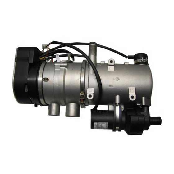
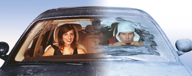
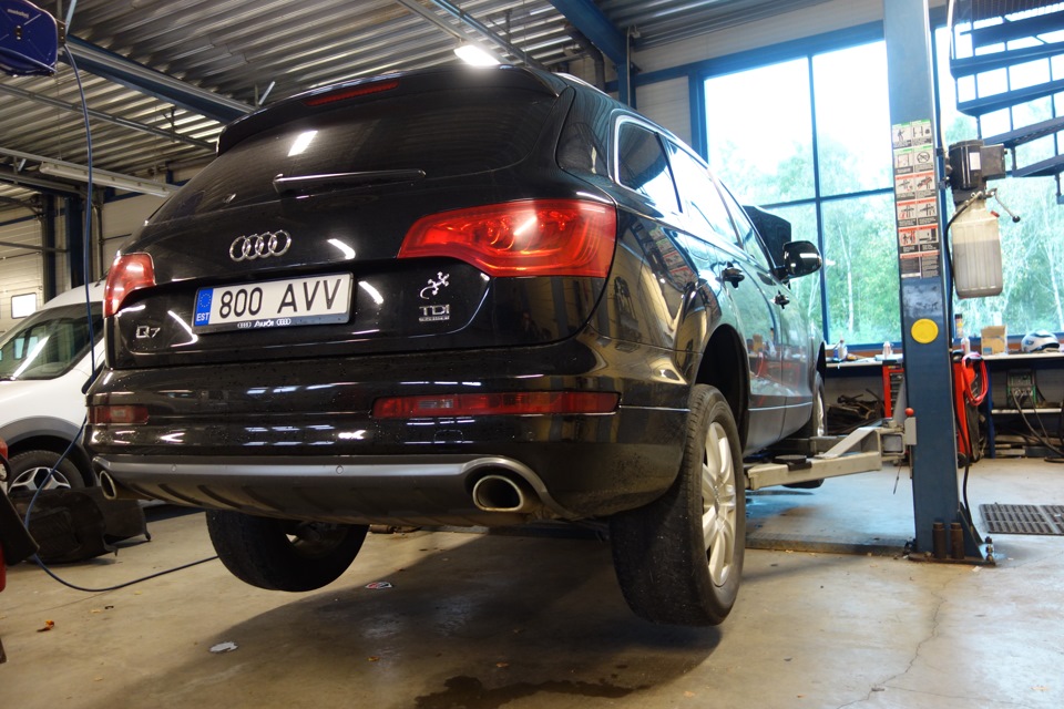
Вот уже почти как год являясь владельцем кушки, прошлую зиму я провел как рядовой владелец дизельной машины — в ожидании прогрева двигателя, чтобы отопить салон. Вообщем, штатная Вебасто не работала, более того, она вовсе была снята еще у предыдущего владельца. Прогнозы его были неутишительные и мне не сильно хотелось вкладываться на круглую сумму в первые месяцы владения авто.
Тем не менее, отопитель был успешно отремонтирован и теперь тепло гарантировано!
А проблема заключалась в следующем. Исходя из результатов диагностики, Вебасто выдавала ошибку:
01414 — Combustion-Air Blower (V6)
007 — Short to Ground
Или, как это отображается в спец. прогремме Webasto Thermo Test V2.12:
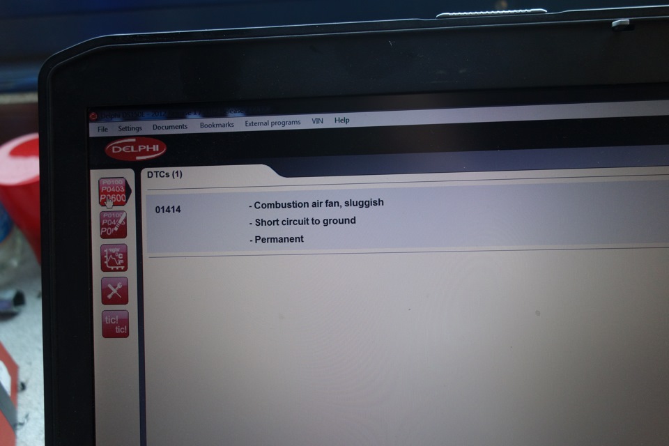
Исходя из вышеописанного следует закономерный вывод — не дует нагнетатель в камеру сгорания.
Симптомом может быть срабатывание вебасты через раз или вовсе ноль эмоций со стороны отопителя.
ОД, разумеется, пошлет на замену камеры вкупе с мозгами и вентилятором разом, это 600-1000 евро у нас, плюс работа и прошивка на машине.
Более продвинутые конторы, занимающиеся вебастами, посоветуют для начала махнуть вентилятор (код W1322649A — у нас 125 евро), а после, если не поможет (а оно вряд ли поможет), менять мозги (~300евро + прошивка) и надеяться на чудо.
Но не найдется той конторы, которая выдаст то, что написано ниже.
Как успел выяснить за один из вечеров, болячка это распространенная у отопителей, прослуживших 5+ лет. Большая часть меняют все по очереди, выкладывая немалые суммы за комплектующие и работу. В единичных случаях у русского пытливого ума срабатывает мысль проверить вентилятор и сделать закономерные выводы…
Далее процесс.
Снятый подопытный:
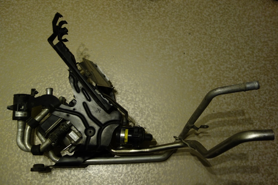
Мозги (плата управления) находится со стороны разъемов.
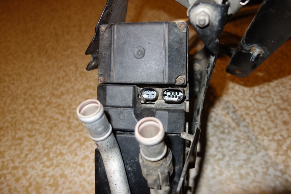
Там же, под трубками, под кожухом прячется злосчастный нагнетатель воздуха:
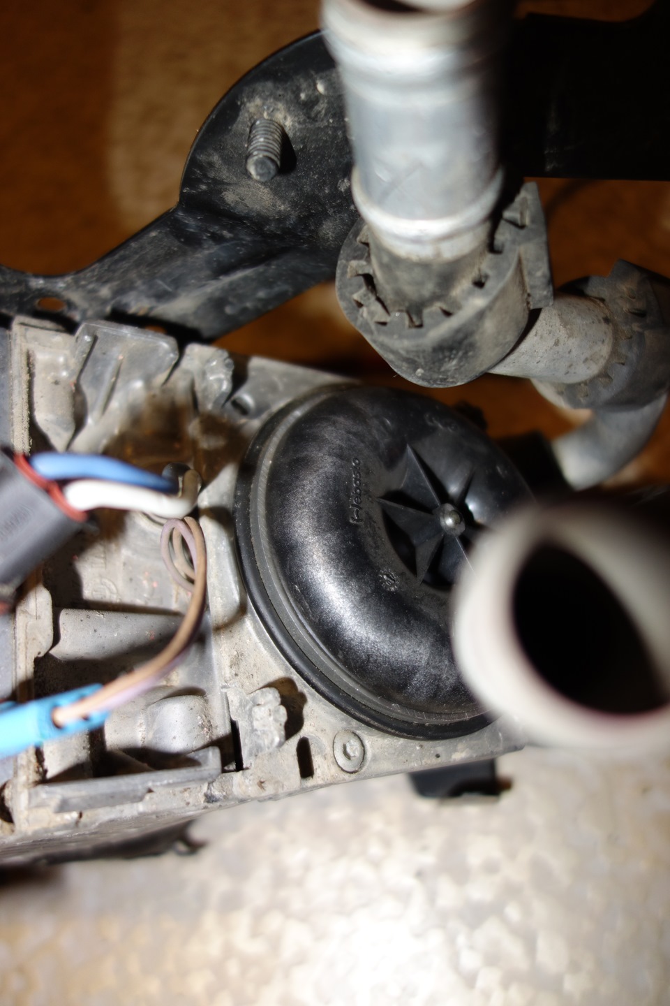
Питание его — тонкие коричневые провода, уходящие в корпус. Второй разъем с более толстыми — керамический элемент накала.
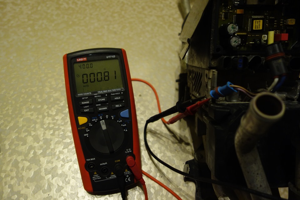
Сопротивление мотора должно быть в пределах 1 Ома. Это значит, что либо он рабочий, либо замкнули щетки. Но контакт есть, и это уже хорошо!
При подключении 12В нагнетатель бодро оживает, издавая знакомые звуки…
Отлично! Значит, черед лезть в мозги!
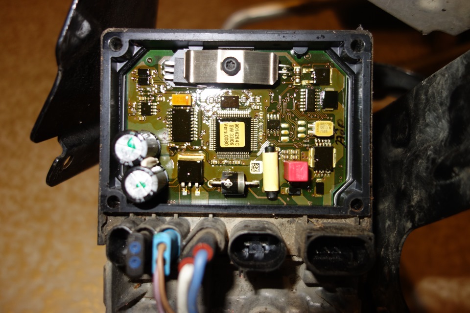
Плата управления снята. Вся в лаке, чтобы не окислялась. Долго мучить не буду, и скажу прямо.
Основная болячка Webasto Thermo Top C/D/E в том, что при частых перепадах температур от -30 до +100гр отваливается пайка на круглых резисторах.
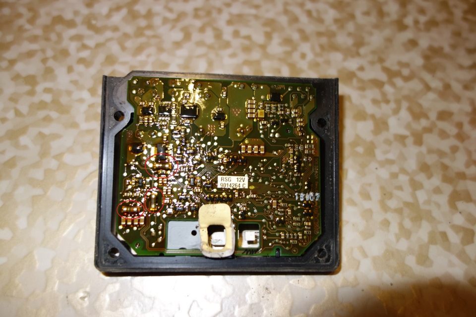
При активном ковырянии пальцами или пинцетом можно определить виновника торжества:
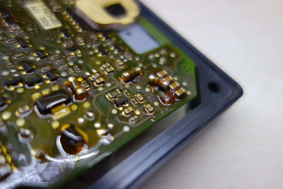
Визуально это практически невозможно разглядеть — на площадках со временем появляются кольцевые трещины, видимые только при хорошем увеличении:
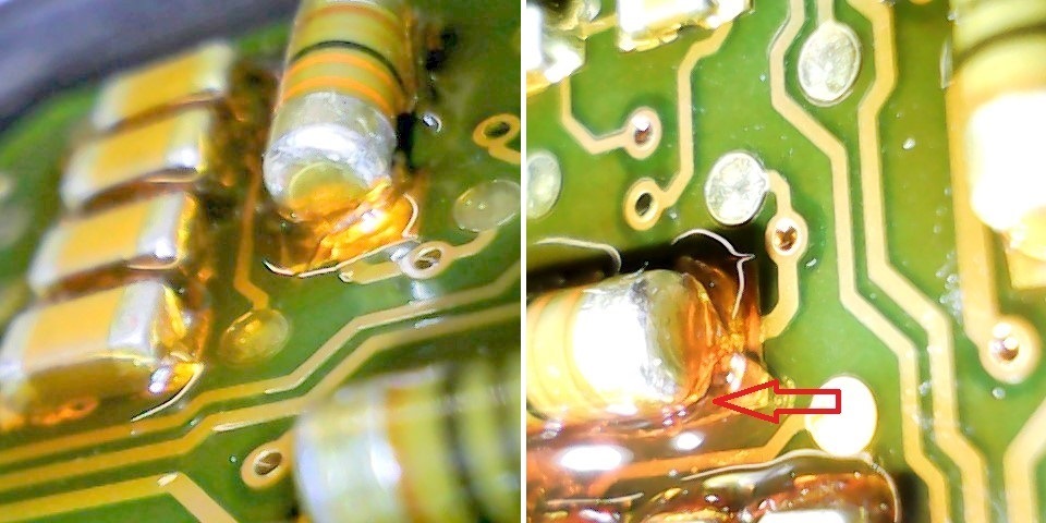
Берем в руки паяльник, 5 минут работы и собираем все обратно!
ВСЁ! На этом весь ремонт, альтернатива которому — новый блок отопителя за 600-1000евро!
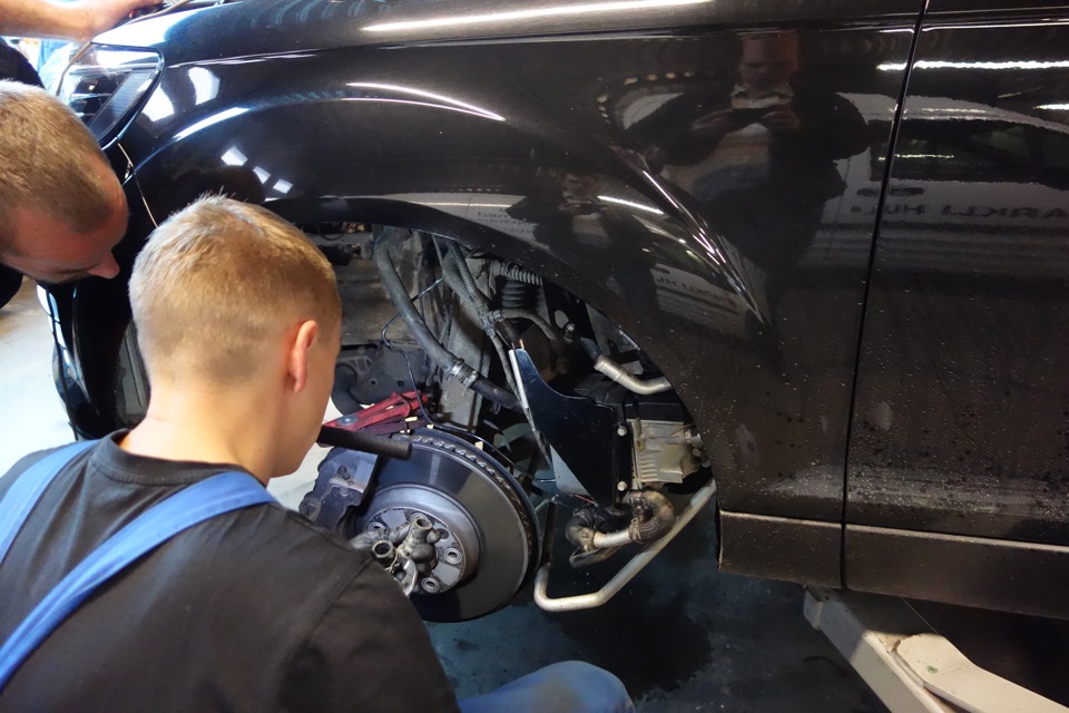
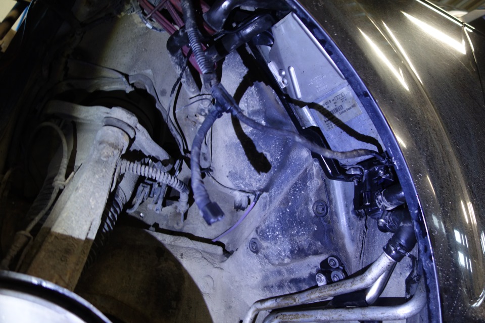
Еще одна хорошая новость — при определенной сноровке можно снять-поставить плату управления, не снимая вебасто с машины! Находится это все в недрах левого крыла. Снимаем колесо, локер (подкрылок) и видим доступ:
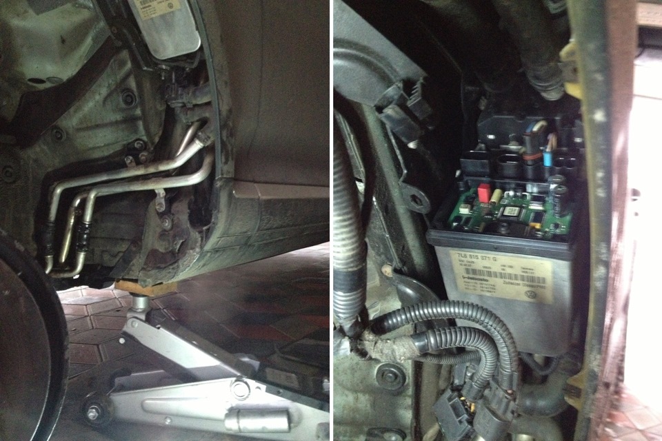
Поскольку у меня отопитель был на руках и его надо было грамотно установить, за эту работу я решил не браться, и поехал к более опытным установщикам.
Советую крупную контору Parkli HL для таллинцев — работают быстро, час стоит 36 евро. Мне все поставили на место за 2,5 часа (взяли за 2) вместе с диагностикой и проверками. Не пожалел, что к ним обратился.
Почти готово, места себе не находил…
Все, установка завершена! Но не все так просто, как хотелось бы…
Важный момент! Если вебасто много раз не запускалась, то она намеренно сядет в собственную защиту! Ее диагностикой зачастую не выявить — все ошибки стерты и не появляются. Все должно работать, но не хочет!
А это ничто иное, как очередная попытка заставить владельца поменять живую вебасто на новую.
На деле нужно снять блокировку с помощью VAG-COM, которая находится:
— Блок 18 — Aux. Heat
— Adaptation (10)
— канал 07 — ставим «1» и жмем Save!
После выполнения данных манипуляций улыбка на лице владельца Q7 расплывается в предвещении теплого салона по утрам! Первый успешный старт после более, чем года простоя!
После нескольких минут работы приставшая грязь начала испаряться, в результате чего дым немного пошел и через капот. Это нормально при долгом простое вебасто!
Если же это происходит зачастую, стоит обратить внимание на беспрепятственное продувание камеры сгорания! Возможно, вентилятор дает потихоньку о себе знать…
В итоге под тахометром появился долгожданный значок работающей вебасто!
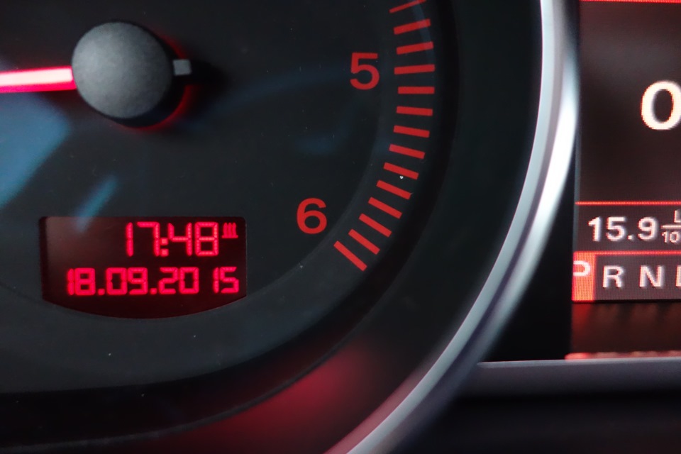
Вот такие дела! На данном этапе я очередной раз сэкономил на ремонте не одну сотню евро. И охотно верю, что этот отчет очень придется кстати отдельным владельцам не обязательно Q7, столкнувшимся с подобной проблемой!
Не спешите менять блоки, хватит кормить дилеров! Почаще читайте форумы и соответствующие тематические сайты — это поможет направить сэкономленные деньги в нужное русло!
Кстати, может кому понадобится мануал по Webasto Thermo Top на русском.
Теперь и я к зиме готов! Не важно, сколько градусов будет за окном.
Но впереди еще один важный этап, который я постараюсь осуществить до наступления холодов!
Следите за обновлениями и узнаете, о чем пойдет речь в следующий раз!
- Manuals
- Brands
- Webasto Manuals
- Water Heater
- Thermo Top V
- Workshop manual
-
Contents
-
Table of Contents
-
Troubleshooting
-
Bookmarks
Quick Links
Luft-Heizgeräte
Water heaters
Visit www.butlertechnik.com for more technical information and downloads.
www.butlertechnik.com
03/2003
Workshop Manual
Thermo Top V
Type Thermo Top V (Petrol)
Type Thermo Top V (Diesel)
Related Manuals for Webasto Thermo Top V
Summary of Contents for Webasto Thermo Top V
-
Page 1: Water Heaters
Visit www.butlertechnik.com for more technical information and downloads. Luft-Heizgeräte 03/2003 Water heaters Workshop Manual Thermo Top V Type Thermo Top V (Petrol) Type Thermo Top V (Diesel) www.butlertechnik.com…
-
Page 2
Webasto training course and have the appropriate technical documentation, special tools and special equipment. NEVER try to install or repair Webasto heating or cooling systems if you have not completed a Webasto training course, you do not have the necessary technical skills and you do not have the technical documentation, tools and equipment available to ensure that you can complete the installation and repair work properly. -
Page 3: Table Of Contents
Visit www.butlertechnik.com for more technical information and downloads. Thermo Top V Table of Contents Table of Contents Introduction …………….101 Contents and purpose.
-
Page 4
Table of Contents Thermo Top V Operating tests …………… 601 General . -
Page 5
Visit www.butlertechnik.com for more technical information and downloads. Thermo Top V Table of Contents Packing, Storage and Shipping …………1001 10.1 General. -
Page 6
Cross-sectional functional model of Thermo Top V water heater ……201… -
Page 7: Introduction
This workshop manual contains all necessary information directly at the vehicle manufacturer’s plant as original equip- and instructions for the repair of Thermo Top V water heat- ment. ers. Normally, there is no need to use additional documentation.
-
Page 8: General Information
Webasto. The same applies if repairs are carried out incorrectly or with the use of parts other than gen- uine spare parts. This will result in the invalidation of the type approval for the heater and therefore of its ho- mologation / EC type licence.
-
Page 9: Fig. 201 Cross-Sectional Functional Model Of Thermo Top V Water Heater
Combustion air inlet Fuel inlet Exhaust outlet Fig. 201 Cross-sectional functional model of Thermo Top V water heater Combustion-air fan unit/control unit The combustion air fan supplies the air required for the combustion process from the combustion air inlet to the combustion chamber.The combustion-air fan unit contains:…
-
Page 10: Fig. 203 Standard Connector Plate With Amp Connector Basket
Visit www.butlertechnik.com for more technical information and downloads. General description Thermo Top V Diesel/petrol burner Connector plate variants The processing of the fuel-air mixture and the actual com- bustion take place in the burner. The fuel flows into the pre- heating chamber with the shut-off valve opened, where it is at first heated up.
-
Page 11: Fig. 208 Diesel Burner Without Fuel Preheating
Visit www.butlertechnik.com for more technical information and downloads. Thermo Top V General description For information on removing and installing the burner, see section 9.2.5 and 9.2.7. IMPORTANT Ensure that the correct burner is always used, as otherwise malfunctions and/or damage will occur on the heater and its service life will be reduced! 2.2.1 Fuel preheating…
-
Page 12: Fig. 212 Solenoid Valve
Visit www.butlertechnik.com for more technical information and downloads. General description Thermo Top V Heat exchanger The heat generated in the heat exchanger by combustion is transferred to the coolant circuit. The heat exchanger consists of an inner and an outer sec- Solenoid valve tion, which are sealed off with an O-ring.
-
Page 13: Fig. 216 Dp40/Dp41 Metering Pump
Visit www.butlertechnik.com for more technical information and downloads. Thermo Top V General description Metering pump The metering pump is a combined transport, metering and shut-off system for supplying fuel from the vehicle’s tank to the heater. For information on checking and installing the metering pump, see section 8.6.2.2.
-
Page 14
Visit www.butlertechnik.com for more technical information and downloads. General description Thermo Top V Page for notes www.butlertechnik.com… -
Page 15: Fig. 301
In case of a heater lock-out, the fault must be identified with 7) Switching off of glow plug (glow plug ramp) the Webasto Thermo Test PC diagnosis, the fault memory
 Flame-monitor measuring phase must be printed out and the faults must be deleted. Then 9) Combustion operation at full load (5 kW) the cause of the fault must be eliminated.
 -
Page 16: Fig. 302 Unlocking Heater
NOTE heater control. The combustion is ended and the run-on As the Thermo Top V auxiliary heater is not switched on begins. In the process, the combustion air fan continues to with a heater control, but instead receives the On signal…
-
Page 17
Visit www.butlertechnik.com for more technical information and downloads. Thermo Top V Description of operation Switch-off or new switch-on signals are processed accord- ing to the following rules: 1. A switch-off signal on a heater control always as priority irrespective of the heater operating state. -
Page 18: Description Of Operation
Visit www.butlertechnik.com for more technical information and downloads. Description of operation Thermo Top V Page for notes www.butlertechnik.com…
-
Page 19: Fig. 401
(permitted function range) Heater dimensions Length 222 mm Width 91 mm Height 144/180 mm Weight 2.1 kg Fig. 401 Technical data for Thermo Top V Circulating pump 4849 4847 Econ Volume flow against 0.14 bar 500 l/h 450 l/h Rated voltage…
-
Page 20
Visit www.butlertechnik.com for more technical information and downloads. Technical data Thermo Top V Page for notes www.butlertechnik.com… -
Page 21: Fig. 501 Overview Of Possible Faults
If there is doubt as to whether the parts are reusable, then Fig. 501 Overview of possible faults new parts should generally be installed. The overview only shows some of the possible faults. The Webasto Service Hotline must be contacted in individual cases. www.butlertechnik.com…
-
Page 22: Fig. 502 Overview Of Functional Analysis Of Heater And Components
Test resistance of the metering pump at +20 °C = 5.2 ohms ± 5 % as described in section 8.6.2.2 Measure delivery rate with Webasto Thermo Test PC Diagnosis as described in section 8.6.2.2 — Petrol: 34 to 42 ml in 180 sec. at 7 Hz.
-
Page 23: Fault Lock-Out Due To Fault On Heater
Unlock as described in section 5.2.2 and installation instructions/installation sug- gestion Control unit (fault memory) Read out fault memory with Webasto Thermo Test PC Diagnosis, then print out and clear fault memory. Include fault log when sending heater to Webasto.
-
Page 24: Troubleshooting
Visit www.butlertechnik.com for more technical information and downloads. Troubleshooting Thermo Top V Page for notes www.butlertechnik.com…
-
Page 25: General
CO meter (e.g. from MSI). 11.5 V. The CO setting is carried out with Webasto Thermo Test PC 5 Switch on the heater with the heater control or the Diagnosis. Webasto Thermo Test PC Diagnosis.
-
Page 26: Fig. 602
6.3.1.3 Testing solenoid valve 6.3.1.1 Testing fan unit Only for diesel burners with solenoid valve. The fan must be tested with the Webasto Thermo Test PC Diagnosis V 2.08 (or higher) as follows: Testing cold resistance: Connect the contacts 1 and 2 of connector X6 (see Fig. 701)
-
Page 27: Electrical Test Of Glow Plug
Visit www.butlertechnik.com for more technical information and downloads. Thermo Top V Operating tests 6.3.1.4 Electrical test of glow plug The cold resistance must be checked using a multimeter with the 4-conductor measuring principle. Multimeters without the 4-conductor measuring principle may not be used for this purpose.
-
Page 28
Visit www.butlertechnik.com for more technical information and downloads. Operating tests Thermo Top V www.butlertechnik.com… -
Page 29: Fig. 701 Connector Assignment Of Heater
General Fig. 701 shows the plug assignment on the control unit. Fig. 702 shows the circuit of the Thermo Top V heater, additional heater and 12 V digital timer. See section 7.2 for legend of wiring diagram. X1 = Connection of vehicle wiring harness (radio remote control, control of metering pump)
-
Page 30: Fig. 702 Wiring Diagram Of Thermo Top V Additional Heater And 12 V Digital Timer
Visit www.butlertechnik.com for more technical information and downloads. Circuit diagrams Thermo Top V Fig. 702 Wiring diagram of Thermo Top V additional heater and 12 V digital timer. www.butlertechnik.com…
-
Page 31
Visit www.butlertechnik.com for more technical information and downloads. Thermo Top V Circuit diagrams Legend for wiring diagram Cable cross-sections Cable colours < 7.5 m 7.5 — 15 m blue brown 0.5 mm 0.75 mm yellow green 0.75 mm 1.0 mm grey 1.0 mm… -
Page 32
Visit www.butlertechnik.com for more technical information and downloads. Circuit diagrams Thermo Top V Page for notes www.butlertechnik.com… -
Page 33: Fig. 801 Circulating Pump U4849 And U4847 Econ Installation Positions
Visit www.butlertechnik.com for more technical information and downloads. Thermo Top V Servicing work Servicing work General • Check fastening of circulating pump and metering pump for damage This section describes the servicing work that can be carried • Conduct operating test of heater as described in section out on the heater when it is installed.
-
Page 34: Fig. 802 Pipe/Hose Connections
In addition, the operation of the pump must be tested as fol- Correct lows: When starting the heater, a slight vibration must be felt on the pump. When controlling with the Webasto Thermo Test Clip PC Diagnosis with maximum power, a soft pump noise must be audible.
-
Page 35: Fig. 804 Information Sign Of Dp40/Dp41 Metering Pump
Visit www.butlertechnik.com for more technical information and downloads. Thermo Top V Servicing work Overview of uses for metering pumps Delivery quantity of metering pumps DP40 and DP41 Metering pump Modulation Diesel Petrol frequency of DP41 ID No. 9009529_ Diesel heater with solenoid metering valve (see section 2.2.2)
-
Page 36: Removal
1 Interrupt power supply of heater by removing 20 A blade fuse from Webasto fuse holder. All coolant and fuel connections must be checked for leaks and secure attachment during a trial run of the heater. If the 2 Separate connectors on heater.
-
Page 37: Fig. 901 Dismantling Heater
This section describes the permissible repair work on the pull out of control unit (Q) in axial direction. Thermo Top V heater while removed. If it is dismantled fur- ther, any and all warranty claims are voided. An operating Release connector cover (P) on side facing away from test must be conducted after all repairs.
-
Page 38: Fig. 902 Installing Air-Intake And Exhaust Connection Piece
Visit www.butlertechnik.com for more technical information and downloads. Repair Thermo Top V 9.2.2 Assembling heater IMPORTANT When screwing on the water connection pieces and the sensors, do not recut the thread several times. The screw For information on installing new temperature sensors must be carefully screwed into the existing thread by hand (G, Fig.
-
Page 39: Fig. 904 Installing Water Connection-Piece Variant B Without Teeth
The locking lug must be engaged in the connection piece as shown. Engaging is carried out mechanically at Webasto, which is why the entire unit, consisting of the retaining plate and the connection piece, must always be ordered.
-
Page 40: Fig. 907 Cable Routing Of Glow Plug
Visit www.butlertechnik.com for more technical information and downloads. Repair Thermo Top V NOTE ID No. of burner Only for diesel burner with fuel preheating: the heating cartridge of the fuel preheating may not be removed! NOTE Only for diesel burners with solenoid valve: the solenoid valve cannot be removed! 9.2.6 Cable routing for glow plug on burner…
-
Page 41: Fig. 909 Heat Exchanger
Visit www.butlertechnik.com for more technical information and downloads. Thermo Top V Repair 3. Loosen screw (2, Fig. 901). 9.2.10 Heat exchanger 4. Remove retaining spring (F) and pull sensors out of heat Existing soot deposits must be completely removed with a exchanger (sensors are not accessible from inside).
-
Page 42: Fig. 910 Cable Routing For Temperature Sensor And Overheating Sensor With Water Connection-Piece Variant A
Visit www.butlertechnik.com for more technical information and downloads. Repair Thermo Top V Wrong Correct Fig. 910 Cable routing for temperature sensor and overheating sensor with water connection-piece variant A blue Fig. 911 Cable routing for temperature sensor and overheating sensor with water connection-piece variant B…
-
Page 43: Fig. 1001 Preferred Position Of Tt-V Heater For Storage And Transport
Packing, Storage and Shipping 10.1 General 10.3 Transport If the heater or its components are sent to Webasto AG for The heater can be transported in any position. testing or repair, it must be cleaned and packed in such a…
-
Page 44
Visit www.butlertechnik.com for more technical information and downloads. Packing, Storage and Shipping Thermo Top V Page for notes 1002 www.butlertechnik.com… -
Page 45
Visit www.butlertechnik.com for more technical information and downloads. www.butlertechnik.com… -
Page 46
Visit www.butlertechnik.com for more technical information and downloads. Webasto AG Postfach 80 D — 82131 Stockdorf Germany National: Hotline: 01805 93 22 78 (€ 0,14 aus dem deutschen Festnetz) Hotfax: 0395 5592 353 Hotmail: hotline@webasto.de www.webasto.de International: www.webasto.com www.butlertechnik.com…
 Flame-monitor measuring phase must be printed out and the faults must be deleted. Then 9) Combustion operation at full load (5 kW) the cause of the fault must be eliminated.