-
Contents
-
Table of Contents
-
Troubleshooting
-
Bookmarks
Quick Links
Reference Manual
Ed 22
January 2017
MAS 2600
Tank Contents Transmitter
Related Manuals for Emerson MAS 2600
Summary of Contents for Emerson MAS 2600
-
Page 1
Reference Manual Ed 22 January 2017 MAS 2600 Tank Contents Transmitter… -
Page 2
Damcos A/S and Rosemount Tank Radar AB accepts no responsibility for any errors that may appear in this publication. As each system may be configured for each delivery, the content and illustrations in this manual may differ from your system. Copyright © Damcos A/S, 2017 Reference Manual for MAS 2600 in English… -
Page 3: Table Of Contents
MAS2600: Table of Contents Reference Manual January 2017 Ed 22 Table of Contents Description and Technical Data ……..3 Description and Operation .
-
Page 4
Reference Manual MAS2600: Table of Contents Ed 22 January 2017… -
Page 5: Description And Technical Data
MAS2600: Description and Technical Data Reference Manual January 2017 Ed 22 Description and Technical Data…
-
Page 6
Reference Manual MAS2600: Description and Technical Data Ed 22 January 2017… -
Page 7: Description And Operation
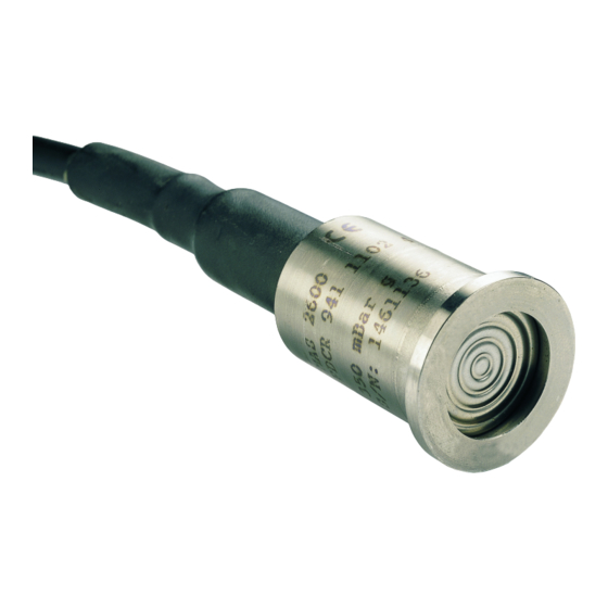
Ed 22 Description and Operation MAS 2600 Tank Contents Transmitter The MAS 2600 is a 2-wire 4-20 mA level transmitter consisting of a transducer, an amplifier and an interconnecting cable. Transducer The transducer is a pressure sensitive silicon micro strain gauge sensor mounted in a glass to metal seal.
-
Page 8: Technical Specification
Reference Manual MAS2600: Description and Technical Data Ed 22 January 2017 Technical Specification Gauge 0 — 3.5 / 0 — 7 / 0 — 16 / 0 — 35 m H Transducer Ranges Absolute 0 — 20.394 / 0 — 35.690 m H ±…
-
Page 9: Transmitter Dimensions
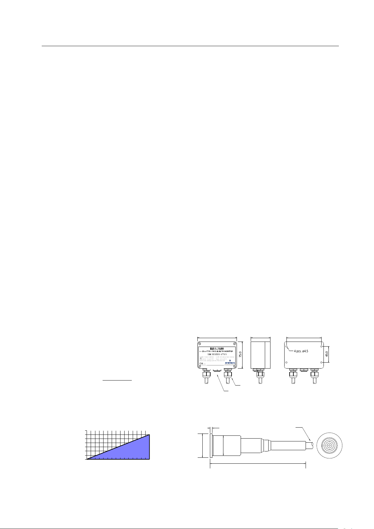
MAS2600: Description and Technical Data Reference Manual January 2017 Ed 22 Power Supply The Power Supply can vary from 17-33 VDC. Permissible load resistance is shown graphically below. (KOhm) = loop max. — 17 V) / 32 mA loop Transmitter Dimensions Amplifier Box Transducer…
-
Page 10
Reference Manual MAS2600: Description and Technical Data Ed 22 January 2017… -
Page 11: Ordering Information
MAS2600: Ordering Information Reference Manual January 2017 Ed 22 Ordering Information…
-
Page 12: Mas2600 Ordering Information
Reference Manual MAS2600: Ordering Information Ed 22 January 2017 MAS 2600 Ordering Information Type Absolute Transducer Gauge Transducer High Temperature Gauge Transducer Transducer Ranges 3,5 mH O gauge 7,0 mH O gauge 16,0 mH O gauge 35,0 mH O gauge or 0,8 to 3,5 bar absolute…
-
Page 13: Type
MAS2600: Ordering Information Reference Manual January 2017 Ed 22 Type MAS 2600 -XXX-XX-X/XX Type Absolute Trans- The absolute transducer has no breather pipe, because it refers to ducer absolute vacuum. An atmospheric pressure sensor is used to compen- sate for the atmospheric pressure. The absolute transducer is espe- cially suitable for open deck applications, where the amplifier box may be exposed to flooding.
-
Page 14: Measuring Ranges
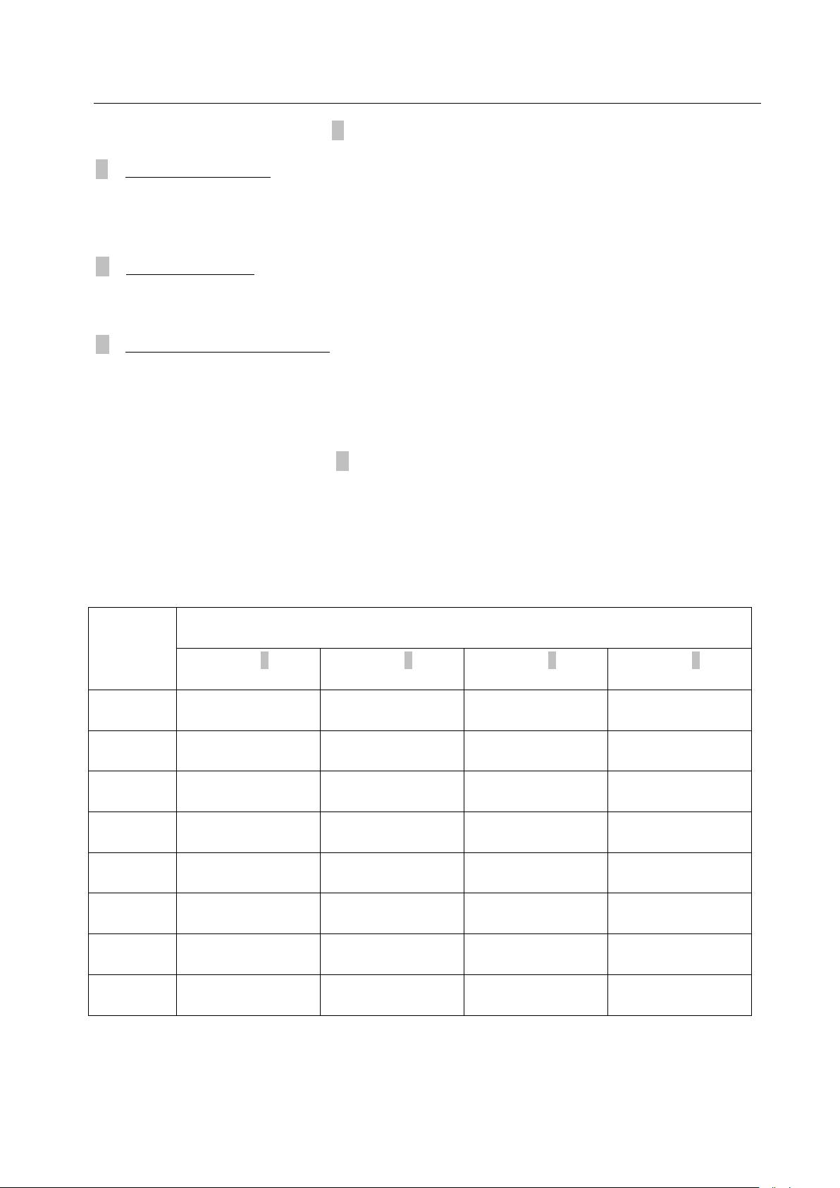
MAS 2600 -XXX-XX-X/XX Gauge Transmitter The MAS 2600 Gauge Transmitter is supplied in 4 ranges. In the programmable amplifier the measur- ing range is divided into 8 sub-ranges and operated by means of the range select switch. The transmitter output signal can be adjusted to 20 mA within the sub-ranges as of the table below.
-
Page 15
The transducer measures the height of the fluid from the transducer diaphragm to the surface of the fluid, including the fluid in the vent pipe. MAS 2600 Amplifier box 2 6 0 0 S E R I E S — 2 0 m A… -
Page 16
Turn amplifier range select switch to range No. 6. Draft Vent pipe min. 1” MAS 2600 amplifier box 2 6 0 0 S E R I E S 4 — 2 0 m A I R E T R A N S… -
Page 17: Temperature Sensor
Reference Manual January 2017 Ed 22 Temperature Sensor MAS 2600 -XXX-XX-X/XX The transducer can be supplied with a built-in Pt100 temperature sensor. The temperature sensor will only give a proper reading, if the transducer is an internally mounted type. Temperature Sensor Without temperature sensor.
-
Page 18: Cable
80C, and high temperature cable for applications with temperatures up to 125C. The trans- ducer cable is delivered in whole meters. To make the MAS 2600 transmitter easy to install, and for later service purposes, the transducer cable should be as short as possible, though considering the position of the transducer and amplifier box.
-
Page 19: Mounting Methods
MAS2600: Ordering Information Reference Manual January 2017 Ed 22 Mounting Methods MAS 2600 -XXX-XX-X/XX Brackets for Internal Mounting (dwg no. P022P010) 2600 S E R IE S 4- 20 mA TW O W IR E TR ANSM ITTE R S/ N: 2 600 CE R T IF ICATE R E F .:…
-
Page 20
Reference Manual MAS2600: Ordering Information Ed 22 January 2017 Pole Mounting (dwg no. P022P011) 2600 SE RIE S 4- 20 mA TW O W IRE TR ANSM ITTE R S/ N: 2600 CERTIFICATE RE F.: 90- C.95948 amb.: — 40 t o + 85 ° C L int = 20 uH Cint = 10 nF Umax = 33 V… -
Page 21
MAS2600: Ordering Information Reference Manual January 2017 Ed 22 1” Pipe End Mounting (dwg no. P022P015) 2 6 0 0 S E R I E S 4 — 2 0 m A I R E T R A N S M I T T E E E X a S / N : 2 6 0 0… -
Page 22
Reference Manual MAS2600: Ordering Information Ed 22 January 2017 Flange Mounting (dwg no. P022P013) 2 6 0 0 S E R I E S 4 — 2 0 m A I R E T R A N S M I T T / N : 2 6 0 0 C E R T I F I C A T E R E F . -
Page 23
MAS2600: Ordering Information Reference Manual January 2017 Ed 22 Flexible Rubber Tube Mounting (dwg no. P022P001) 2 6 0 0 S E R I E S 4 — 2 0 m A I R E T R A N S M I T T / N : 2 6 0 0 C E R T I F I C A T E R E F . -
Page 24
The customer can exchange the MAS 2600 transmitter by ordering a G022B085 and a G022B082 together with the new MAS 2600 transducer. It must clearly be specified that it is a replacement for an MAS 2600 XXX-XX-P/XX. -
Page 25
MAS2600: Ordering Information Reference Manual January 2017 Ed 22 DN25 flange with 1” ball valve (dwg no. P022P019) 2 6 0 0 S E R I E S 4 — 2 0 m A I R E T R A N S M I T T x E E S / N : 2 6 0 0… -
Page 26: Amplifier Box
Amplifier Box MAS 2600 -XXX-XX-X/XX The MAS 2600 amplifier box is manufactured of polyester, which has the strength and stability of alu- minium, insulation and resistance properties of plastics. Color code RAL 7000. The amplifier box is protected to the level of IP 56 and must be mounted outside the tank, e.g. in the engine room or other dry areas.
-
Page 27: Amplifier Pcb
MAS2600: Ordering Information Reference Manual January 2017 Ed 22 Amplifier PCB MAS 2600 -XXX-XX-X/XX The PCB is available in different types for the different transducers. Amplifier PCB Without amplifier PCB. Programmable output range. The amplifier can be calibrated to 4-20 mA output in whatever range wanted within the transducer range.
-
Page 28
Reference Manual MAS2600: Ordering Information Ed 22 January 2017… -
Page 29: Intrinsically Safe Installation
MAS2600: Intrinsically Safe Installation Reference Manual January 2017 Ed 22 Intrinsically Safe Installation Description of the Ex safety information and Intrinsically Safe Installation MAS 2600…
-
Page 30
Reference Manual MAS2600: Intrinsically Safe Installation Ed 22 January 2017… -
Page 31: Intrinsic Safety
Safety Certifications The MAS 2600 Level Transmitter is intrinsically safe and meets the requirements of all the major clas- sification societies. The MAS 2600 has the following safety Ex-certifications: •…
-
Page 32: Intrinsically Safe Installation
MAS2600: Intrinsically Safe Installation Ed 22 January 2017 Intrinsically Safe Installation The MAS 2600 is designed for use in an approved intrinsically safe installation. The amplifier is fitted with a label describing the IS category: Item Explanation Serial number — production year…
-
Page 33
Be sure to order and use sensor cable with the right temperature specification. Check that the ambient temperature for the entire cable run do not exceed the max limit for the cable. MAS 2600 contain no repairable parts. Repairing or fixing the circuit or replacing components may impact the intrinsic safety. -
Page 34
Reference Manual MAS2600: Intrinsically Safe Installation Ed 22 January 2017 The entity concept allows inter-connections of intrinsically safe apparatus to associated apparatus not specifically examined in combination as a system. The approved values of maximum open circuit voltage and maximum short circuit current and maximum output power, for the associated appara- tus must be less than or equal to the maximum safe input voltage (U ), maximum safe input current ), and maximum safe input power (P… -
Page 35: Installation
MAS2600: Installation Reference Manual January 2017 Ed 22 Installation Installation and Handling the MAS 2600…
-
Page 36: Handling
MAS2600: Installation Ed 22 January 2017 Handling The MAS 2600 transducer is a highly sensitive electronic piece of equipment and proper handling is most important. To avoid damaging the transducers: • NEVER lift by the cable if transducer is mounted with fittings.
-
Page 37: Installation
MAS2600: Installation Reference Manual January 2017 Ed 22 Installation As part of the installation please check that: • the serial numbers on the transducer, amplifier and lid of amplifier box complies. The serial num- bers are found on the S/N on the amplifier box at the bottom line and on the transducer S/N on the range label.
-
Page 38
Reference Manual MAS2600: Installation Ed 22 January 2017… -
Page 39: Testing And Recalibration
MAS2600: Testing and Recalibration Reference Manual January 2017 Ed 22 Testing and Recalibration Testing and Recalibration of the MAS 2600…
-
Page 40: Testing
Reference Manual MAS2600: Testing and Recalibration Ed 22 January 2017 Testing Caution! Please observe that testing and recalibration of transmitters mounted in hazardous areas shall be carried out by Ex qualified personnel. Before dispatch, the MAS2600 transmitter is calibrated in accordance with the requirements speci- fied in the order.
-
Page 41: Recalibrating Gauge Transmitter Using Pressure On The Transducer
MAS2600: Testing and Recalibration Reference Manual January 2017 Ed 22 Recalibrating Gauge Transmitter using Pressure on the Transducer Caution! Please observe that testing and recalibration of transmitters mounted in hazardous areas shall be carried out by Ex qualified personnel. When recalibrating the MAS2600 Gauge Transmitter a pressure calibrator with a range of -1 to 3.5 bar should be used.
-
Page 42: Recalibrating Gauge Transmitter Using Vacuum (For Gauge Transmitters Only)
Reference Manual MAS2600: Testing and Recalibration Ed 22 January 2017 Recalibrating Gauge Transmitter using Vacuum (for gauge transmitters only) Caution! Please observe that testing and recalibration of transmitters mounted in hazardous areas shall be carried out by Ex qualified personnel. An internally mounted transducer can also be recalibrated by using vacuum.
-
Page 43: Recalibrating The Absolute Transmitter Using Pressure On The Transducer
MAS2600: Testing and Recalibration Reference Manual January 2017 Ed 22 Recalibrating the Absolute Transmitter using Pressure on the Transducer Caution! Please observe that testing and recalibration of transmitters mounted in hazardous areas shall be carried out by Ex qualified personnel. When recalibrating the MAS2600 Absolute Transmitter a pressure calibrator with a range of -1 to 3.5 bar should be used.
-
Page 44
Reference Manual MAS2600: Testing and Recalibration Ed 22 January 2017… -
Page 45: Maintenance And Troubleshooting
MAS2600: Maintenance and Troubleshooting Reference Manual January 2017 Ed 22 Maintenance and Troubleshooting…
-
Page 46: Maintenance
Reference Manual MAS2600: Maintenance and Troubleshooting Ed 22 January 2017 Maintenance Caution! Please observe that testing and recalibration of transmitters mounted in hazardous areas shall be carried out by Ex qualified personnel. Marine Tank Management recommends that the following to be checked annually: Visual inspection of the cable, transducer and amplifier.
-
Page 47: Trouble Shooting
Please observe that testing and recalibration of transmitters mounted in hazardous areas shall be carried out by Ex qualified personnel. If the MAS 2600 transmitter is not functioning in accordance with Marine Tank Management instruc- tions, check that: the 24 VDC power supply has been correctly connected, and is between 17-33 VDC.
-
Page 48: Mas2600 Test Sheet
Emerson Process Management Marine Tank Management Damcos A/S, Service Department FAX.: +45 5578 7272 Ship name Yard NB no. MAS 2600 Transducer serial no. MAS 2600 Amplifier serial no. Tank name Liquid in tank Ballast Other The tank is Full…
-
Page 49: Index
MAS2600: Index Reference Manual January 2017 Ed 22 Index Numerics Mounting Methods ……….17 1” Pipe End Mounting………. 19 Operation ………….. 5 Ordering Information……….. 10 Absolute Transducers ………. 11 Absolute Transmitter……….. 12 Amplifier …………… 5 Amplifier Box…………24 Pole Mounting …………. 18 Amplifier PCB …………
-
Page 50
Reference Manual MAS2600: Index Ed 22 January 2017… -
Page 52
©2017 Emerson. All rights reserved. Emerson Automation Solutions Damcos A/S The Emerson logo is a trademark and service mark of Emerson Electric Co. Rosemount and the Aaderupvej 41 Rosemount logotype are registered trademarks of Rosemount Inc. Damcos and the Damcos DK-4700 Naestved logotype are trademarks of Damcos A/S.
Скачать
Installation & User Manual
Ed 19UK
June 2013
MAS2600
Tank Contents Transmitter
Краткое содержание страницы № 1
Installation & User Manual
Ed 19UK
June 2013
MAS2600
Tank Contents Transmitter
Краткое содержание страницы № 2
Installation & User Manual Ed 19UK June 2013 Table of contents Description and Operation ………………………………………………………………………………… 3 MAS2600 Tank Contents Transmitter ………………………………………………………………………………….3 Application ………………………………………………………………………………………………………………………..3 Intrinsically Safe
Краткое содержание страницы № 3
Installation & User Manual June 2013 Ed 19UK Description and Operation MAS2600 Tank Contents Transmitter The MAS2600 is a 2-wire 4-20 mA level • Differential version: For measuring of transmitter consisting of a transducer and an both pressure and vacuum measuring. amplifier interconnected by a 6-core vented cable. The amplifier is housed in a sea water resistant polyester casing (IP56). Transducer: The transducer is a pressure sensitive silicon Application mi
Краткое содержание страницы № 4
Installation & User Manual Ed 19UK June 2013 Technical Specifications Output Current: 4-20 mA DC, loop powered 2-wire system. Transducer Ranges: Current Limiting: Gauge: 0-3.5 / 0-7 / 0-16 / 0-35 m H O. 2 Max: 25 mA Absolute: 0-20.394 / 0-35.690 m H O. 2 Sensor Materials: Programmable Measuring Ranges: Housing: Titanium Grade 2 Each transducer range is programmable in 8 Diaphragm: Titanium Grade 4 steps. Operating Temperature Ranges: Accuracy: Transdu
Краткое содержание страницы № 5
Installation & User Manual June 2013 Ed 19UK MAS2600 Ordering Information Type A absolute transducer G gauge transducer H high temperature gauge transducer Transducer Ranges 1 3,5 mH O gauge or high temp. 2 2 7,0 mH O gauge or high temp. 2 3 16,0 mH O gauge or high temp. 2 4 35,0 mH O gauge or 0,8 – 3,5 bar absolute 2 7 0,8 – 2,0 bar absolute Temperature Sensor 0 without 1 Built-in Pt100 (Not available for IS installations ) Cable Max. 300 meters –
Краткое содержание страницы № 6
Installation & User Manual Ed 19UK June 2013 Type MAS2600-XXX-XX-X/XX A: Absolute Transducer. The absolute transducer has no breather pipe, because it refers to absolute vacuum. An atmospheric pressure sensor is used to compensate for the atmospheric pressure. The absolute transducer is especially suitable for open deck applications, where the amplifier box may be exposed to flooding. G: Gauge Transducer. The gauge transducer is fitted with a breather pipe at the back of the di
Краткое содержание страницы № 7
Installation & User Manual June 2013 Ed 19UK Absolute Transmitter: The MAS2600 Absolute Transmitter is available in two ranges. The output signals are calibrated as follows: Transducer type 4 : 0.8 — 3.5 bar abs Transducer type 7 : 0.8 — 2.0 bar abs Selecting the Measuring Range: When selecting the measuring range it is important to consider the tank height, vent pipe height, the tank type and the specific gravity (SG) of the tank contents. The transducer measures
Краткое содержание страницы № 8
Installation & User Manual Ed 19UK June 2013 Absolute Transducers: The Absolute Transmitter is typically used if the amplifier is exposed to water, e.g. on open deck. The Absolute Transmitter is available in 2 ranges: 0-20 and 0-35 mH O. In practice this means 10 2 mH O less than the nominal range because of the atmospheric pressure which must be taken into 2 consideration when choosing the transducer. A transducer with an effective range larger than the tank height should
Краткое содержание страницы № 9
Installation & User Manual June 2013 Ed 19UK Draft: Vent pipe min. 1” MAS2600 amplifier box 2600 SERIES 4-20 mA TWO WIRE TRANSMITTER x a 2600 EEX i CT5 S/N: CERTIFICATE REF.: 90-C.95948Tamb.: -40 to +85 °C Lint = 20 uH Cint = 10 nF Umax = 33 V I 45 m K= < A MARINE AUTOMATION DENMARK Weather deck Min. draft Sensor pos. above Ships hull Class approved Sea valve Ships hull Transducer measuring range > max. draft minus sensor position.
Краткое содержание страницы № 10
Installation & User Manual Ed 19UK June 2013 Brackets for Internal Mounting — drawing no. G022P010: 2600 SERIES 4-20 mA TWO WIRE TRANSMITTER x a 2600 EEX i CT5 S/N: CERTIFICATE REF.: 90-C.95948Tamb.: -40 to +85 °C Lint = 20 uH Cint = 10 nF Umax = 33 V I K = < 45 mA MARINE AUTOMATION DENMARK Tank top Bulkhead 125.0 45.0 160.0 Tank bottom The brackets are U-shaped and manufactured of 2 mm SS 316L plated steel. Diameter of mounting holes: 11.5 mm. The transducer is secured by m
Краткое содержание страницы № 11
Installation & User Manual June 2013 Ed 19UK 1” Pipe End Mounting — drawing no. G022P015: 2600 SERIES 4-20 mA TWO WIRE TRANSMITTER x 2600 EEX ia CT5 S/N: CERTIFICATE REF.: 90-C.95948Tamb.: -40 to +85 °C Lint = 20 uH Cint = 10 nF Umax = 33 V I 45 K= < mA MARINE AUTOMATION DENMARK 80,0 55,0 24.0 25,0 Tank top Bulkhead Tank bottom The thread collar and the nut are manufactured of SS 316L steel. The gaskets are made of nitrile rubber. Note: Max torque
Краткое содержание страницы № 12
Installation & User Manual Ed 19UK June 2013 Flexible rubber tube mounting 80 ºC — drawing no. G022P001: 2600 SERIES 4-20 mA TWO WIRE TRANSMITTER x EEX ia CT5 S/N: 2600 CERTIFICATE REF.: 90-C.95948Tamb.: -40 to +85 °C Lint = 20 uH Cint = 10 nF Umax = 33 V I K < = 45 mA MARINE AUTOMATION DENMARK Tank top H Bulkhead Tank bottom A top flange made of SS 316L connected to rubber tube by a tightening clip using a special tool. The opposite hose end covers the tran
Краткое содержание страницы № 13
Installation & User Manual June 2013 Ed 19UK DN25 flange with 1” ball valve – drawing no. G022P019: 2600 SERIES 4-20 mA TWO WIRE TRANSMITTER x a 2600 EEX i CT5 S/N: CERTIFICATE REF.: 90-C.95948Tamb.: -40 to +85 °C Lint = 20 uH Cint = 10 nF Umax = 33 V I K < = 45 mA MARINE AUTOMATION DENMARK Tank top Bulkhead Tank bottom Flange, valve and nut are manufactured of SS 316L steel. The gaskets are made of nitrile rubber. Note: Max torque 20 Nm (slightly
Краткое содержание страницы № 14
Installation & User Manual Ed 19UK June 2013 Amplifier Box MAS2600-XXX-XX-X/XX The MAS2600 amplifier box is manufactured in polyester, which has the strength and stability of aluminium, insulation and resistance properties of plastics. Colour code RAL 7000. The amplifier box is protected to the level of IP 56 and must be mounted outside the tank, e.g. in the engine room or other dry areas. The amplifier box is available with a PG9 hole for silicone gel filling to protect t
Краткое содержание страницы № 15
Installation & User Manual June 2013 Ed 19UK Amplifier PCB MAS2600-XXX-XX-X/XX The PCB is available in different types for the different transducers, with or without terminals for Pt100 temperature sensor. 0: Without amplifier PCB. P or S: Programmable output range. The amplifier can be calibrated to 4-20 mA output in whatever range wanted within the transducer range. Calibration is made by means of dip switches and potentiometers. D or M: Differential output range. The
Краткое содержание страницы № 16
Installation & User Manual Ed 19UK June 2013 Handling The MAS2600 transducer is a highly sensitive electronic piece of equipment and proper handling is most important. To avoid damaging the transducers: • NEVER lift by the cable if transducer is mounted with fittings. • NEVER remove the protection cap in front of the diaphragm before installation. • NEVER knock the transducer. • NEVER apply pressure to the diaphragm in any way whatsoever, whether using fingers, tools
Краткое содержание страницы № 17
Installation & User Manual June 2013 Ed 19UK Installation Prior to installation please check that: • the serial numbers on the transducer, amplifier and lid of amplifier box agree. The serial numbers are to be found on the inside of the lid of the amplifier box on the bottom line — amplifier S/N and transducer S/N on the range label. • the transducer is fitted in the correct tank. • the transducer is correctly connected to the amplifier. NOTE: The white and brown wires i
Краткое содержание страницы № 18
Installation & User Manual Ed 19UK June 2013 If the amplifier box is installed in an area with over pressure or negative pressure in relation to the atmospheric pressure in the tank, the breather tube must be directed to an area with atmospheric pressure equalling the pressure inside the tank. This applies to gauge transmitters only. For absolute transmitters this has no affect, due to the reference to absolute vacuum and not atmospheric pressure. This is also the reason why no breath
Краткое содержание страницы № 19
Installation & User Manual June 2013 Ed 19UK Intrinsically Safe Installation The MAS2600 is designed for use in an approved intrinsically safe installation. The amplifier is fitted with a label describing the IS category: S/N: XXXXXX-YYYY DEMKO 11 ATEX 146506X IECEx ULD 10.0013X Ui: 29V Ii: 93 mA Li: 20µH Ci: 60 nF Pi: 0.68 W II 2(1) G Ex ia IIC T4 Tamb.: -20 to +80 °C Damcos A/S, Aaderupvej 41,DK-4700, Naestved Where S/N : serial number – production y
Краткое содержание страницы № 20
Installation & User Manual Ed 19UK June 2013 Before installing intrinsically safe units within an approved installation, it is essential to ensure that there are no deviations from the conditions of the order or the requirements of the approved block schematic diagram and the following related instructions: 1. No circuits other than those shown on the drawing are permitted. There must be no interconnection to any other circuits. 2. The intrinsically safe cabling must not be conne
-
Emerson MAS 2600 — page 1
Installa tion & User Ma nual Ed 19 UK June 2013 MAS 2600 Tank Con tents Tra nsmi tte r …
-
Emerson MAS 2600 — page 2
Installa tion & User Manual Ed 19 UK June 2013 Page 2 of 28 Table of con ten ts Description and Operation ………………………………………………………………………………… 3 MAS2600 Tan k Conte nts Tr ansm itte r …………………………………………………………………………………. 3 Applica …
-
Emerson MAS 2600 — page 3
Installa tion & User Ma nual June 2013 Ed 19 UK Page 3 of 28 C ERTI FI C ATE RE F. : 4- 20 m A L i n t = 2 0 uH x MARI NE AUT OMATI ON DE NMARK S/N: Um ax = 33 V T Ci nt = 1 0 n F C i EE X a 90- C.95948 T5 am b . : -40 to +85 ° C I 4 5 mA K = < 2600 T WO WI RE T RA NS MI T T E R 2600 SERI ES S/N 46374 1. 5 bar g PDCR- 941-1 MAS 2600 DMS Des …
-
Emerson MAS 2600 — page 4
Installa tion & User Manual Ed 19 UK June 2013 Page 4 of 28 0 100 200 300 400 500 600 700 17 20 23 26 29 32 Load resistance (ohm) Power supply (V) Max. load resistanc e at v arious power supply T echnic al Spe cifi cati ons Trans ducer Ra nges: Gauge: 0-3.5 / 0-7 / 0-16 / 0-35 m H 2 O. Absolute: 0-20.394 / 0-35.690 m H 2 O. Progra mmable Mea su …
-
Emerson MAS 2600 — page 5
Installa tion & User Ma nual June 2013 Ed 19 UK Page 5 of 28 MAS2600 Or deri ng Infor mati on Typ e A absolute transducer G gaug e transducer H high temperature gaug e transducer Transduce r Ranges 1 3,5 mH 2 O gauge or high tem p. 2 7,0 mH 2 O gauge or high tem p. 3 16,0 mH 2 O gaug e or high temp. 4 35,0 mH 2 O gaug e or 0,8 – 3,5 bar absol …
-
Emerson MAS 2600 — page 6
Installa tion & User Manual Ed 19 UK June 2013 Page 6 of 28 Type MAS2600-X XX — XX — X/XX A: Absolute Transducer. The absolute transducer has no breather pipe, because it refers to absolute vacuum. An atmospheric pressure sensor is used to compensate for the atmospheric pressure. The abs olute t rans ducer is es pecial l y suitabl e for open d …
-
Emerson MAS 2600 — page 7
Installa tion & User Ma nual June 2013 Ed 19 UK Page 7 of 28 M AS 2600 Am pli f i er box Fl ange mounted G022P 013 Sensor pos . above l owest poi nt T ankhei ght V ent pi pe hei ght TWO WIRE TRANSM ITTER 2600 SERIES 90-C.95948 T5 Cint = 10 nF C CERTIFICATE REF.: 4-20 mA Lint = 20 uH x i EE X a MARINE AUTOMATION DENMARK S/N: Umax = 33 V T amb.: …
-
Emerson MAS 2600 — page 8
Installa tion & User Manual Ed 19 UK June 2013 Page 8 of 28 Absol ute Tr ans duce rs : The Absolute Transmitter is typically used if the amplifier is exposed to water, e.g. on open deck. The Absolu te Transmitter is av ailable i n 2 rang es: 0 -20 and 0-35 mH 2 O. In practice this means 10 mH 2 O less than the nominal range beca use of the atmo …
-
Emerson MAS 2600 — page 9
Installa tion & User Ma nual June 2013 Ed 19 UK Page 9 of 28 Class approved Sea valv e TWO WIRE TRAN SMITTER 2600 SERIES 90-C.95948 T5 Cint = 10 nF C CERTIFICATE REF.: 4-20 mA Lint = 20 uH x i EE X a MARINE AUTOMATION DENMARK S/N: Umax = 33 V T amb.: -40 to +85 °C I 45 mA K= < 2600 W eathe r d eck MAS2600 am plifier box Sens or p os. ab ove …
-
Emerson MAS 2600 — page 10
Installa tion & User Manual Ed 19 UK June 2013 Page 10 of 28 Brac kets f or In terna l M ounti ng — drawi ng no. G022P010 : Bulkhead T ank bott om TWO WIRE TRAN SMITTER 2600 SERIES 90-C.95948 T5 Cint = 10 nF C CERTIFICATE REF.: 4-20 mA Lint = 20 uH x i EE X a MARINE AUTOMATION DENMARK S/N: Umax = 33 V T amb.: -40 to +85 °C I 45 mA K = < 260 …
-
Emerson MAS 2600 — page 11
Installa tion & User Ma nual June 2013 Ed 19 UK Page 11 of 28 19,5 D k d b TWO WI RE TR ANSMI TTE R 2600 SERIES 90-C.95948 T5 Cint = 10 nF C CERTIFICATE REF.: 4-20 mA Lint = 20 uH x i EE X a MARINE AUTOMATI ON DENMARK S/N: Umax = 33 V T amb.: -40 to +85 °C I 45 mA K= < 2600 Tank t op Tank bot t om Bul khe ad 25,0 55, 0 80, 0 34.0 26,0 24.0 …
-
Emerson MAS 2600 — page 12
Installa tion & User Manual Ed 19 UK June 2013 Page 12 of 28 Tank bot t om H Bul khe ad Lint = 20 uH CERTIFICATE REF. : 4-20 m A Tank t op x S/N: MARINE AUTOMATI ON DENMARK Umax = 33 V 90-C.95948 TWO WIRE TRAN SMITTER Cint = 10 nF X EE i a T5 C 2600 SERIES I 4 5 mA amb.: -40 to +85 °C < = K T 2600 Bul khe ad Tank bot t om Tank t op TWO WI R …
-
Emerson MAS 2600 — page 13
Installa tion & User Ma nual June 2013 Ed 19 UK Page 13 of 28 Tank bot t om Bul khe ad Tank t op 4-20 mA CERTIFICATE REF.: Lint = 20 uH x EE X 2600 amb.: -40 to +85 °C I 45 mA MARINE AUTOMATION DENMARK TWO WIRE TRANSM I TTER 90-C.95948 Umax = 33 V Cint = 10 nF C a i T5 T S/N: < = K 2600 SERIES DN25 f lange wi th 1” ball va lve – dra win …
-
Emerson MAS 2600 — page 14
Installa tion & User Manual Ed 19 UK June 2013 Page 14 of 28 Amplifier Box MAS2600- XXX — XX — X/ XX The MAS2600 amplifier box is manufactured in poly ester, which has the strength and stability of aluminium, insulation and resistance properties of plastics. Colour code RAL 7000. The amplifier box is protected to the level of IP 56 and must be …
-
Emerson MAS 2600 — page 15
Installa tion & User Ma nual June 2013 Ed 19 UK Page 15 of 28 Amplifier P CB MAS2600- XXX — XX — X/XX The PC B is avail able in different t ypes for the d ifferen t tran s ducers, with or without terminals for Pt100 temperature sensor. 0: Without amplifie r PCB. P or S : Program mable ou tput ran ge. Th e ampli fier can b e cal ibrated t o 4 -2 …
-
Emerson MAS 2600 — page 16
Installa tion & User Manual Ed 19 UK June 2013 Page 16 of 28 Handling The MAS2600 transducer is a highly sensitive electronic piece of equipment and proper handling is most importan t. To avoid damaging the transducers : • NEVER lift by the ca ble if transduc er is mounted with fittings. • NEVER remove the protection cap in front of the dia …
-
Emerson MAS 2600 — page 17
Installa tion & User Ma nual June 2013 Ed 19 UK Page 17 of 28 Installati on Prior to insta llation pleas e check tha t: • the serial numbers on the transducer, amplifier and lid of amplifier box agree. The serial numbers are to be found on the inside of the lid of the amplifier box on the bottom line — ampli fier S/N and transd ucer S /N on t …
-
Emerson MAS 2600 — page 18
Installa tion & User Manual Ed 19 UK June 2013 Page 18 of 28 If the a mplifier bo x is installed in an a rea with over pressure or negative pressure in relation to the atmospheric pressure in the tank, the breather tube must be directed to an area with atmospheric pressure equalling the pressure inside the tank. This applies to ga uge transmitt …
-
Emerson MAS 2600 — page 19
Installa tion & User Ma nual June 2013 Ed 19 UK Page 19 of 28 Intrinsi call y S afe Installation The MAS2600 is designed for use in an approved intrinsically safe installation. The amplifier is fitted with a label de scribing the IS category : S/N: XXXXXX- YYY Y DEMKO 11 ATEX 146506X IECEx ULD 10.0013X Ui: 29V Ii: 93 mA Li: 20µH C i: 60 nF Pi: …
-
Emerson MAS 2600 — page 20
Installa tion & User Manual Ed 19 UK June 2013 Page 20 of 28 Before in st alling intrins ically safe un its within an ap proved insta llation, it is essential to e nsure that there are no deviations from the conditions of the order or the requirements of the approved block schematic diagram and the following related instructions: 1. No circuits …
-
Emerson MAS 2600 — page 21
Installa tion & User Ma nual June 2013 Ed 19 UK Page 21 of 28 4- 20 m A Hazar dous ar ea Saf e ar ea Any 28V / 300R Shunt zener di ode s af t y bar r i er or Ex r epeat er cer t i fi ed to Ex I a I IC. T r ans ducer Am pl i f i er box MARI NE AUT OMATI ON DENMARK Cint = 10 nF 2600 SERIES 4-20 mA CERTIFICATE REF.: Lint = 20 uH x EE X i a C amb.: …
-
Emerson MAS 2600 — page 22
Installa tion & User Manual Ed 19 UK June 2013 Page 22 of 28 T esting and R ec alibr ating Please observe that testing and recalibration of sensors mounted in hazardous arias shall be carried out of Ex qualified pe rsonnel. Testin g Before di spatch, the MA S2600 transm itter i s calib rated in ac cord ance wit h the requ irem ents specifi ed i …
-
Emerson MAS 2600 — page 23
Installa tion & User Ma nual June 2013 Ed 19 UK Page 23 of 28 Recalibrating Gauge Trans mitter using Vacuu m (for gauge trans mitters only) An internally mounted transducer can also be recalibrated by using vacuum. 1. Check that the tank is empty. 2. Check t hat the ran ge sel ect swi tch on t he ampli fier i s correctl y set. 3. Set the calibr …
-
Emerson MAS 2600 — page 24
Installa tion & User Manual Ed 19 UK June 2013 Page 24 of 28 Recalibr ati ng t he Abso lute T ransm itter using Test Cup type G0 22 S100 When recal ibr ating the MAS2600 Absol ute Tran smit ter a press ure cal i brator w ith a range o f -1 to 3.5 bar should be used. It should have an accuracy of 0.05% FS or better, as well as a 4½ digit millia …
-
Emerson MAS 2600 — page 25
Installa tion & User Ma nual June 2013 Ed 19 UK Page 25 of 28 EXAMPLE: If the range of the transducer is 3.5 bar abs and the atmospheric pressure is 1005 mbar. Calculated output at atmospheric pressure: mA @ Atm .p ress = 4 16 1005 800 3500 800 + − − * ( ) = 5.215 mA Calculated applied pressure for maximum output: mbarg @ 20 mA = 3500 1005 …
-
Emerson MAS 2600 — page 26
Installa tion & User Manual Ed 19 UK June 2013 Page 26 of 28 Maint enance and T r o uble Shooting Mainten an ce Damcos recommends that the following to be checked annually: 1. Visual inspection of the cable, transducer and amplifier. 2. Compare signal with e.g. hand sounding, and if necessary perform a zero and full- scale calibra tion. Trouble …
-
Emerson MAS 2600 — page 27
Installa tion & User Ma nual June 2013 Ed 19 UK Page 27 of 28 MAS260 0 Tes t sh eet ATT.: Emerson Process Management Marine Solutions Damcos A /S, Service Departm ent F AX . : +45 5578 7272 Nam e: Ship name: Yard: NB No: MAS2600: Transduce r serial n o.: Amp lifier seri al no.: Tank nam e: Liquid in tank HFO: DO: Ballast: Othe r: Th e tan k is …
-
Emerson MAS 2600 — page 28
Installa tion & User Manual Ed 19 UK June 2013 Page 28 of 28 Emerson P rocess Manag ement Damcos A/S Aaderupve j 41 DK — 4700 Naestved T +45 5578 7200 F +45 5578 7272 www. EmersonProcesss. com/mtm ©2013 Emerso n Process Management. All rights res erved. The Emerson logo is a trademark and service mark of Emerson Electric Co. Damcos and the Dam …
 Loading…
Installation & User Manual
Ed 19UK
June 2013
MAS2600
Tank Contents Transmitter

Installation & User Manual
Ed 19UK June 2013
Page 2 of 28
Table of contents
Description and Operation ………………………………………………………………………………… 3
MAS2600 Tank Contents Tra nsmit ter ………………………………………………………………………………….3
Application ………………………………………………………………………………………………………………………..3
Intrinsically Safe in Hazardous Areas …………………………………………………………………………………..3
Type Approvals ………………………………………………………………………………………………………………...3
Technical Specifications …………………………………………………………………………………… 4
MAS2600 Ordering Information ……………………………………………………………………… 5
Type …………………………………………………………………………………………………………………………………6
Measuring Ranges ……………………………………………………………………………………………………………..6
Selecting the Measuring Range ………………………………………………………………………………………..7
Selecting the Transducer Type …………………………………………………………………………………………7
Absolute Transducers ……………………………………………………………………………………………………..8
Basic Rules ……………………………………………………………………………………………………………………8
Forepeak Tank ……………………………………………………………………………………………………………….8
Draft ……………………………………………………………………………………………………………………………..9
Temperature Sensor ……………………………………………………………………………………………………………9
Cable ………………………………………………………………………………………………………………………………..9
Brackets for Interna l Mounting — drawing no. G022 P010 ………………………………………………… 10
Pole Mounting — drawing no. G022P 011 ……………………………………………………………………….. 10
1” Pipe End Mounting — drawing no. G022P015 …………………………………………………………….. 11
Flange Mounting — drawing no. G022P013 …………………………………………………………………….. 11
Flexible rubber tube mounting 80 …………………………………………………………………………………. 12
Flexible PTFE tube mounting ………………………………………………………………………………………. 12
DN25 flange with 1” ball va lve – drawing no. G022 P019 ……………………………………………….. 13
Amplifier Box ………………………………………………………………………………………………………………... 14
Deck Box 165B9035 ………………………………………………………………………………………. 15
Handling ……………………………………………………………………………………………………….. 16
Installation …………………………………………………………………………………………………….. 17
Intrinsically Safe Installation …………………………………………………………………………… 19
Testing and Recalibrating ……………………………………………………………………………….. 22
Testing …………………………………………………………………………………………………………………………… 22
Recalibrating Gauge Tra nsmitter u si ng Te st Cup ty pe G022 S100 ………………………………………… 22
Recalibrating Gauge Transmitter using Vacuum (for gauge transmitters only) ………………………. 23
Recalibrating the Absolu t e Tra nsm itter us ing Te st Cup type G022S100 ……………………………….. 24
Maintenance and Trouble Shooting ………………………………………………………………….. 26
Maintenance …………………………………………………………………………………………………………………… 26
Trouble Shooting ……………………………………………………………………………………………………………. 26
MAS2600 Test sheet ………………………………………………………………………………………………………. 27

Installation & User Manual
June 2013 Ed 19UK
Page 3 of 28
CERTIFICATE REF.:
4—20 mA
Li nt = 20 uH
x
MARINE AUTOMAT ION DENMARK
S/N:
Umax = 33 V
T
Ci nt = 1 0 nF
C
i
EE
X
a
90—C.95948
T5
amb.: —40 to +85 °C
I 45 mA
K=
<
2600
TWO WI RE T RANSMITTER
2600 SERIES
S/N 46374
1.5 bar g
PDCR-941-1
MAS 2600
DMS
Description and Operation
MAS2600 Tank Contents Transmitter
The MAS2600 is a 2—wire 4-20 mA level
transmitter consisting of a transducer and an
amplifier interconnected by a 6—core vented
cable.
Transducer:
The transducer is a pressure sensitive silicon
micro strain gauge sensor mounted in a glass
to metal seal. The sensor is protected by an
isolation diaphragm, electron beam welded
to the transducer housing, with an oil filling
between the sensor and the diaphragm.
Pressure changes on the front of the
diaphragm will bring a resistance change in
the Wheatstone bridge of the transducer.
This change in the Wheatstone bridge will
be transmitted to the amplifier as a change in
the electrical signal.
The transducer is fully welded, housed in
titanium with a titanium diaphragm.
All transducer types are submersible (IP68).
The transducer is available in three versions:
• Gauge version.
• Absolute version.
• High temperature gauge vers io n.
As optional the transducer is available with a
built-in Pt100 temperature sensor.
Amplifier:
The amplifier is available in the following
options:
• Programmable version: Calibration is
made by dip switches and potentiometers.
• Differential version: For measuring of
both pressure and vacuum measuring.
The amplifier is housed in a sea water
resistant polyester casing (IP56).
Application
The MAS2600 has been developed for level
measuring in ballast, oil, service and fresh
water tanks as well as tanks containing
media which are not hostile to titanium.
Intrinsically Safe in Hazardous Areas
The MAS2600 is DEMKO approved for use
with standard transmitter zener barriers or
Ex isolation amplifiers and is Ex ia IIC T4
compliant in accordance with IEC 60079-
0:2007 and IEC 60079-11:2006.
Type Approvals
DNV, GL, LRS, MRS, BV, RINA, KRS,
ABS.
CE marked in accordance with EU directive.
Transducer
Installation & User Manual
Ed 19UK June 2013
Page 4 of 28
0
100
200
300
400
500
600
700
Load resistance (ohm)
Power supply (V)
Max. load resistance
at various power supply
Technical Specifications
Transducer Ranges:
Gauge: 0-3.5 / 0-7 / 0-16 / 0-35 m H
2
O.
Absolute: 0-20.394 / 0-35.690 m H
2
O.
Programmable Measuring Ranges:
Each transducer range is programmable in 8
steps.
Accuracy:
± 0.25% F.S. at 20°C.
Stability:
Max. ± 0.1% / Year.
TEB (Total Error Band):
± 2.0% F.S. at -20 to +80°C.
EMC immunity influence < ±0.5%FS
Overload Capability:
Min. 4 x transducer range with no changes in
calibration.
6 x transducer range burst pressure.
Built—in Temperature Sensor Pt100:
Optional.
Power Supply:
The Power Supply can vary from 17-33
VDC. Permissible load resistance is shown
graphically below. Calculation formula:
R
loop max.
(Kohm) =
Output Current:
4-20 mA DC, loop powered 2-wire system.
Current Limiting:
Max: 25 mA
Sensor Materials:
Housing: Titanium Grade 2
Diaphragm: Titanium Grade 4
Operating Temperature Ranges:
Transducer: -20 to +125°C
Standard cable: -20 to + 80°C
High temperature cable: -20 to +125°C
Amplifier: -40 to + 85°C
Protection Class:
Transducer: IP 68
Amplifier: IP 56
Intrinsic Safety:
Ex ia IIC T4 compliant.
Max. 75 m cable between transducer and
transmitter amplifier.
Transmitter dimensions
Amplifier box:
MARINE AUTOMATION DENMARK
Cint = 10 nF
2600 SERIES
4-20 mA
CERTIFICATE REF.:
Lint = 20 uH
x
EE
X
i
a
C
amb.: —40 to +85 °C
I 45 mA
S/N:
Umax = 33 V
T5
90—C.95948
2600
T
K=
<
TWO WIRE TRANSMITTER
55.0
110.0
75.0
45.0
98.0
PG11
cable gland
1/8″ NPT
vent fitting
4 pcs. ø4.5
Use 4x20mm bolts and nuts
for suspension on a 4mm
thick surface
Transducer:
120.0
3.0
30.0
25.0
6-core vented cable, ø8.0
Front view

Installation & User Manual
June 2013 Ed 19UK
Page 5 of 28
MAS2600 Ordering Information
A absolute transducer
G gauge transducer
H high temperature gauge transducer
1 3,5 mH
2
O gauge or high temp.
2 7,0 mH
2
O gauge or high temp.
3 16,0 mH
2
O gauge or high temp.
4 35,0 mH
2
O gauge or 0,8 – 3,5 bar absolute
7 0,8 – 2,0 bar absolute
0 without
1 Built—in Pt100 (Not available for IS installations )
Cable Max. 300 meters – max 75 meters for IS installations
XX XLPE standard cable length in meters (up to 80°C).
XX FEP high temperature cable length in meters (up to 125°C) (Not IS inst).
0 without fittings
1 brackets for internal mounting
2 pole mounting
3 1″ pipe end mounting
4 flange mounting DN 25
5 flange mounting DN 40
6 flange mounting DN 50
9 flexible rubber tube mounting – 80 ºC (add length in meters)
P flexible PTFE tube mounting – 125 ºC (add length in meters) (Not IS inst)
V DN25 flange / 1” ball valve
0 not supplied
1 standard box with PG 11 / PG 11
2 standard box with PG 11 / PG 13,5
3 standard box with PG 11 / PG 16
5 standard box with PG 13,5 / PG 13,5
6 standard box with PG 11 / PG 11 – filling hole
7 standard box with PG 11 / PG 13,5 – filling hole
8 standard box with PG 11 / PG 16 – filling hole
0 not supplied
without terminals for temperature sensors:
P programmable output range gauge
D differential output range gauge
with terminals for temperature sensors:
S programmable output range gauge
M differential output range gauge
Installation & User Manual
Ed 19UK June 2013
Page 6 of 28
Type MAS2600-XXX—XX—X/XX
A: Absolute Transducer. The absolute transducer has no breather pipe, because it refers to
absolute vacuum. An atmospheric pressure sensor is used to compensate for the atmospheric
pressure. The absolute transducer is especially suitable for open deck applications, where the
amplifier box may be exposed to flooding.
G: Gauge Transducer. The gauge transducer is fitted with a breather pipe at the back of the
diaphragm to compensate for the atmospheric pressure. The breather pipe is connected to a
vent plug in the amplifier box. The gauge transducer is suitable for most applications.
H: High Temperature Transducer. The high temperature transducer is available in gauge version
only. The transducer is mounted with a special high temperature cable and designed for
heated tanks e.g. HFO tanks, and other applications with high tank media temperatures. The
transducer can be flange mounted or internally mounted.
Measuring Ranges MAS2600-XXX-XX—X/XX
Gauge Transmitter:
The MAS2600 Gauge Transmitter is supplied in 4 ranges. In the programmable amplifier the
measuring range is divided into 8 sub-ranges and operated by means of the range select switch.
The transmitter output signal can be adjusted to 20 mA within the following sub-ranges.
Transducer type
Type 1:
0 – 3.5 mH
2
O
Type 2:
0 – 7.0 mH
2
O
Type 3:
0 – 16.0 mH
2
O
Type 4:
0 – 35.0 mH
2
O
1 0.20 – 0.37 mH
2
O 0.20 – 0.30 mH
2
O 0.50 – 0.75 mH
2
O 1.00 – 1.90 mH
2
O
2 0.37 – 0.54 mH
2
O 0.30 – 0.50 mH
2
O 0.75 – 1.00 mH
2
O 1.90 – 2.80 mH
2
O
3 0.54 – 0.73 mH
2
O 0.50 – 0.70 mH
2
O 1.00 – 1.50 mH
2
O 2.80 – 3.90 mH
2
O
4 0.73 – 1.10 mH
2
O 0.70 – 1.10 mH
2
O 1.50 – 2.50 mH
2
O 3.90 – 5.80 mH
2
O
5 1.10 – 1.92 mH
2
O 1.10 – 1.80 mH
2
O 2.50 – 4.00mH
2
O 5.80 – 9.90 mH
2
O
6 1.92 – 3.10 mH
2
O 1.80 – 3.00 mH
2
O 4.00 – 6.00 mH
2
O 9.90 – 15.30 mH
2
O
7 3.10 – 3.50 mH
2
O 3.00 – 4.80 mH
2
O 6.00 – 10.00 mH
2
O 15.30 – 25.10 mH
2
O
8
NOT
APPLICABLE
4.80 – 7.10 mH
2
O 10.00 – 16.00 mH
2
O 25.10 – 35.60 mH
2
O
Installation & User Manual
June 2013 Ed 19UK
Page 7 of 28
MAS 2600 A m plifier box
Flange mounted
G022P013
Sensor pos. above
lowest point
Tankheight
Vent pipe height
TWO WIRE TRANSMITTER
2600 SERIES
90-C.95948
T5
Cint = 10 nF
C
CERTIFICATE REF.:
4-20 mA
Lint = 20 uH
x
i
EE
X
a
MARINE AUTOMATION DENMARK
S/N:
Umax = 33 V
T
amb.: -40 to +85 °C
I 45 mA
K=
<
2600
Absolute Transmitter:
The MAS2600 Absolute Transmitter is available in two ranges.
The output signals are calibrated as follows:
Transducer type 4 : 0.8 — 3.5 bar abs
Transducer type 7 : 0.8 — 2.0 bar abs
Selecting the Measuring Range:
When selecting the measuring range it is important to consider the tank height, vent pipe height,
the tank type and the specific gravity (SG) of the tank contents.
The transducer measures the height of the fluid (water gauge) from the transducer diaphragm to
the surface of the fluid, including the fluid in the vent pipe.
To ensure measuring accuracy a transducer type within the range no. 4, 5, 6, 7 and 8 is
recommended.
Guidelines for selection of transducer measuring ranges are set out in the following.
Selecting the Transducer Type:
Gauge and High Temperature Gauge Transducers:
The Gauge Transmitter is normally used on dry and pressure neutral locations.
The Gauge Transmitter is available in 4 ranges:
0-3.5 mH
2
O.
0-7.0 mH
2
O.
0-16.0 mH
2
O.
0-35.0 mH
2
O.

Installation & User Manual
Ed 19UK June 2013
Page 8 of 28
Absolute Transducers
:
The Absolute Transmitter is typically used if the amplifier is exposed to water, e.g. on open deck.
The Absolute Transmitter is available in 2 ranges: 0-20 and 0-35 mH
2
O. In practice this means 10
mH
2
O less than the nominal range because of the atmospheric pressure which must be taken into
consideration when choosing the transducer.
A transducer with an effective range larger than the tank height should be selected.
Basic Rules:
1. The selected measuring range must be larger than the tank height.
2. The selected measuring range must be larger than
tank height + vent pipe height
2
EXAMPLE: Tank height = 6 m
Vent pipe height = 14 m
1. The selected measuring range must be larger than 6 m due to the height of the tank.
2. The selected measuring range must be larger than
= 10 m due to the total height of the
tank and the vent pipe combined.
Select a transducer with a measuring range of 16 mH
2
O as this is the next measuring range larger
than 10 m.
Turn the range select switch on the amplifier to range No. 7.
Normally the selection of transducer, range select and calibration are done by DAMCOS.
Special consideration applies to e.g. forepeak tanks and draft measuring when selecting the
measuring range of the transducer.
Forepeak Tank:
Transducer measuring range > tank height: Select the next measuring range.
EXAMPLE: Tank height 12 m.
Based on the tank height a transducer with a measuring range of 16 mH
2
O should be selected.
However, due to the dynamic conditions in the forepeak tank, a transducer with a measuring
range of 35 mH
2
O, i.e. the next in line, should be selected.
Turn amplifier range select switch to range No. 6.
Installation & User Manual
June 2013 Ed 19UK
Page 9 of 28
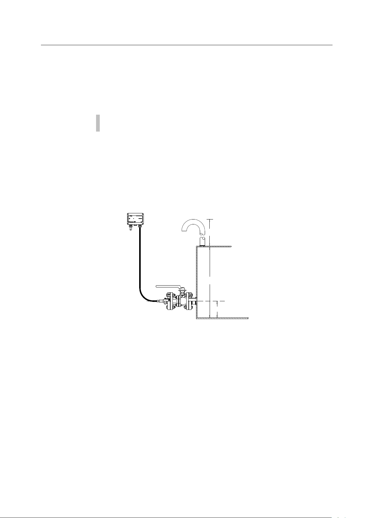
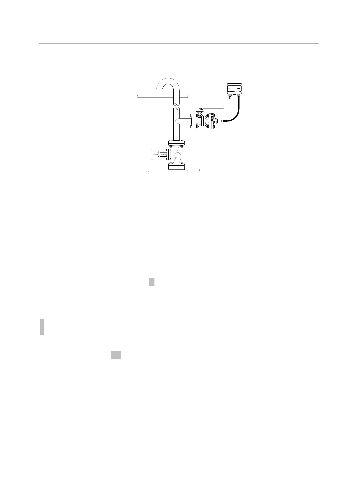
Class approved
Sea valve
TWO WIRE TRANSMITTER
2600 SERIES
90-C.95948
T5
Cint = 10 nF
C
CERTIFICATE REF.:
4-20 mA
Lint = 20 uH
x
i
EE
X
a
MARINE AUTOMATION DENMARK
S/N:
Umax = 33 V
T
amb.: -40 to +85 °C
I 45 mA
K=
<
2600
Weather deck
Ships hull
Vent pipe min. 1”
Draft
:
Transducer measuring range > max. draft minus sensor position.
This rule applies provided the transducer is mounted in accordance with the installation drawing
for draft transmitters (vent pipe min. 1″). The sensor may be mounted direct on the sea valve with
an air release valve if the ship is sailing in calm waters.
If the transducer is installed in tanks which may have excessive dynamic stresses such as e.g.
high pump pressure, long bottomed tanks with a risk of slashing etc., contact Emerson Process
Management Marine Solutions, Damcos.
Temperature Sensor MAS2600-XXX-XX—X/XX
The transducer can be supplied with a built-in Pt100 temperature sensor. The temperature sensor
will only give a proper reading, if the transducer is an internally mounted type.
0: Without temperature sensor.
1: With temperature sensor
Cable MAS2600-XXX—XX—X/XX
Two types of transducer cable is available. The standard cable for applications with temperatures
never exceeding 80°C, and high temperature cable for applications with temperatures up to
125°C. The transducer cable is delivered in whole meters.
For further information require data sheet.
To make the MAS2600 transmitter easy to install, and for later service purposes, the transducer
cable should be as short as possible, though considering the position of the transducer and
amplifier box.
Max. cable length: 300 m.
When installing in hazardous areas max. cable length: 75 m.