Если вам сложно разобраться со специфическими терминами руководства к роутеру D-Link 2640U или у вас его нет, эта простая инструкция поможет вам быстро справиться с настройкой устройства.
Чтобы вы не запутались при подключении роутера, вначале разберем алгоритм подключения и те моменты, которые помогут вам быстрее разобраться с маршрутизатором.
Быстрое знакомство с элементами роутера
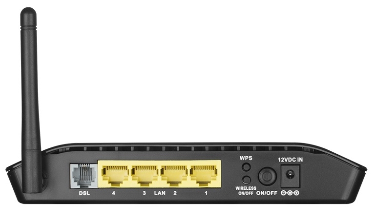
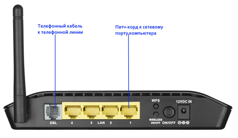
Поверните к себе устройство задней стороной и рассмотрите все элементы. Здесь есть порт DSL, в который подключается телефонный провод, а также четыре порта LAN. Они нужны для подключения к роутеру компьютеров, телевизоров и других устройств вашего дома, оснащенных сетевыми портами. Также один из портов LAN можно использовать в качестве порта WAN для подключения кабеля провайдера, если таковой заходит к вам в дом. Из имеющихся на этой панели кнопок для подключения роутера вам понадобится кнопка питания On/Off и разъем для подключения кабеля к розетке.
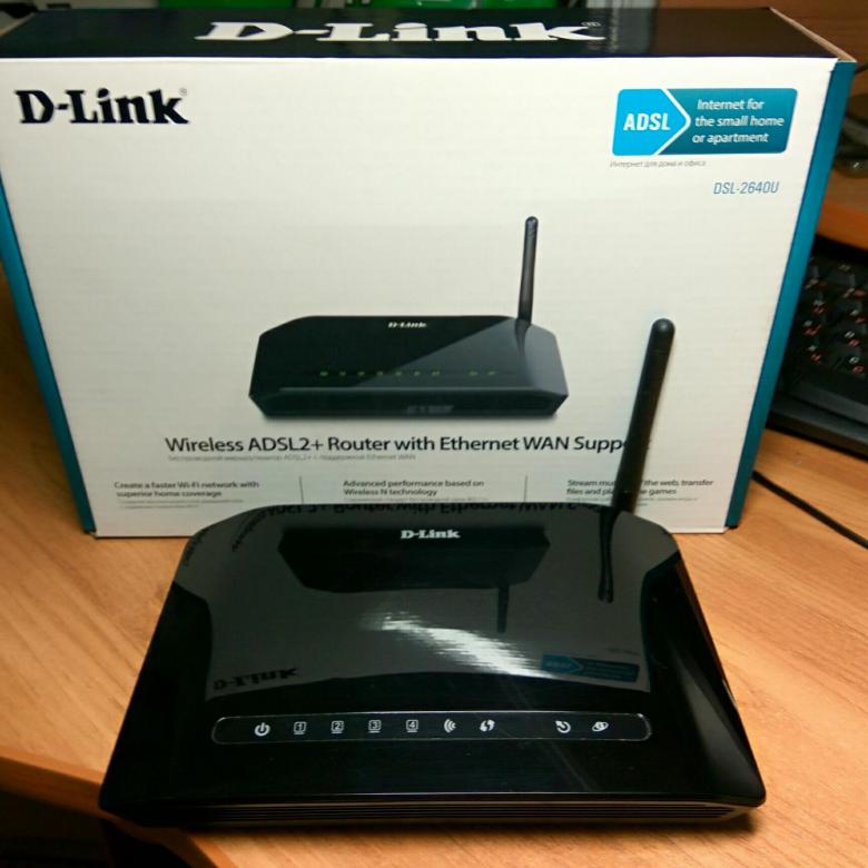
 Теперь изучим обозначения индикаторов, чтобы вы могли в любой момент понять состояние маршрутизатора. Поверните роутер к себе лицевой стороной и рассмотрите значки. Первым слева изображен индикатор питания, который кроме классического состояния «горит» и «не горит» может светиться красным. Этот цвет означает либо загрузку роутера, либо переход в режим аварийного восстановления. Значки с цифрами от 1 до 4 отражают состояние LAN-портов. Например, если вы подключили в порт с цифрой 2 компьютер, то индикатор с цифрой 2 будет гореть постоянно или мигать (если пойдет передача данных между роутером и компьютером). Если один из LAN-портов вы задействуете в качестве WAN-порта для подключения кабеля провайдера, тогда индикатор будет показывать наличие или отсутствие подключения по кабелю.
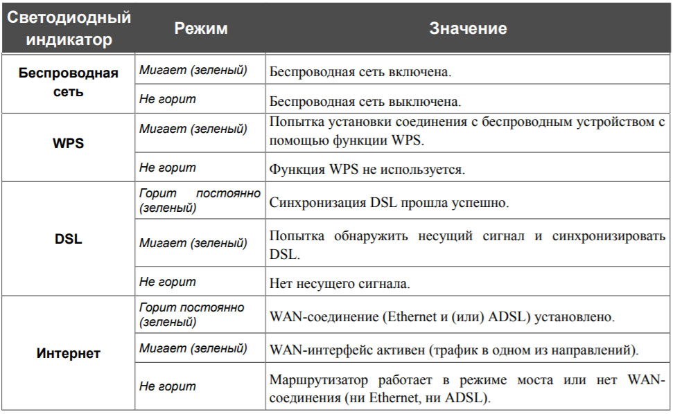
 Следующие четыре значка – это Wi-Fi-сеть, функция WPS, DSL и интернет. Их режимы вам подскажет таблица ниже. Заметим лишь, что последний значок интернета подсказывает, все ли в порядке с подключением роутера к интернету через телефонный провод или кабель провайдера.
Подготовка оборудования
Чтобы роутер раздавал в вашем доме интернет, вам понадобятся такие условия:
- Доступ в интернет через телефонный провод (в DSL-2640U встроен модем) или по кабелю провайдера.
- Устройство, на котором вы будете настраивать роутер. У него должен быть сетевой порт для настройки по кабелю или Wi-Fi-адаптер для настройки по сети Wi-Fi. Также на устройстве должен стоять браузер с включенной поддержкой jаvascript для захода в панель управления или установлена программа Telnet. В роли такого устройства может выступить, например, стационарный компьютер или, ноутбук.

Алгоритм подключения и настройки роутера
- Подключить роутер к интернету.
- Подключить к роутеру управляющее устройство.
- С управляющего устройства ввести данные провайдера и при желании задать свои настройки.
- Подключить к роутеру другие устройства через LAN-порты или через сеть Wi-Fi.
Как подключить роутер D-Link DSL-2640U
Теперь рассмотрим два первых шага приведенного выше алгоритма.
Как подключить роутер к интернету
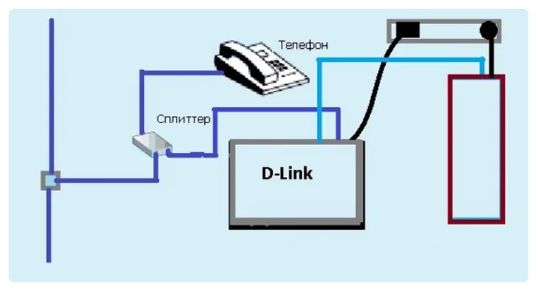
Если к вам в квартиру заходит телефонный провод, достаньте из коробки роутера телефонный кабель и сплиттер. При помощи сплиттера вы подключите к телефонной линии свой домашний телефон, то есть сможете одновременно задействовать телефонную линию и для интернета, и для звонков по стационарному телефону. Телефонный кабель из коробки роутера подсоедините к порту роутера с надписью DSL. Другой его конец вставьте в порт ADSL OUT сплиттера. После этого подключите свой домашний телефон к порту PHONE сплиттера, и включите кабель от телефонной розетки к порту ADSL
IN сплиттера. Картинка ниже поможет вам разобраться с этим подключением.
 Если к вам к дом заходит кабель провайдера, тогда вставьте его в любой порт LAN и запомните, в какой порт вы его подключили. Позднее, вам нужно будет указать именно этот порт через панель управления.
Как подключить роутер к компьютеру
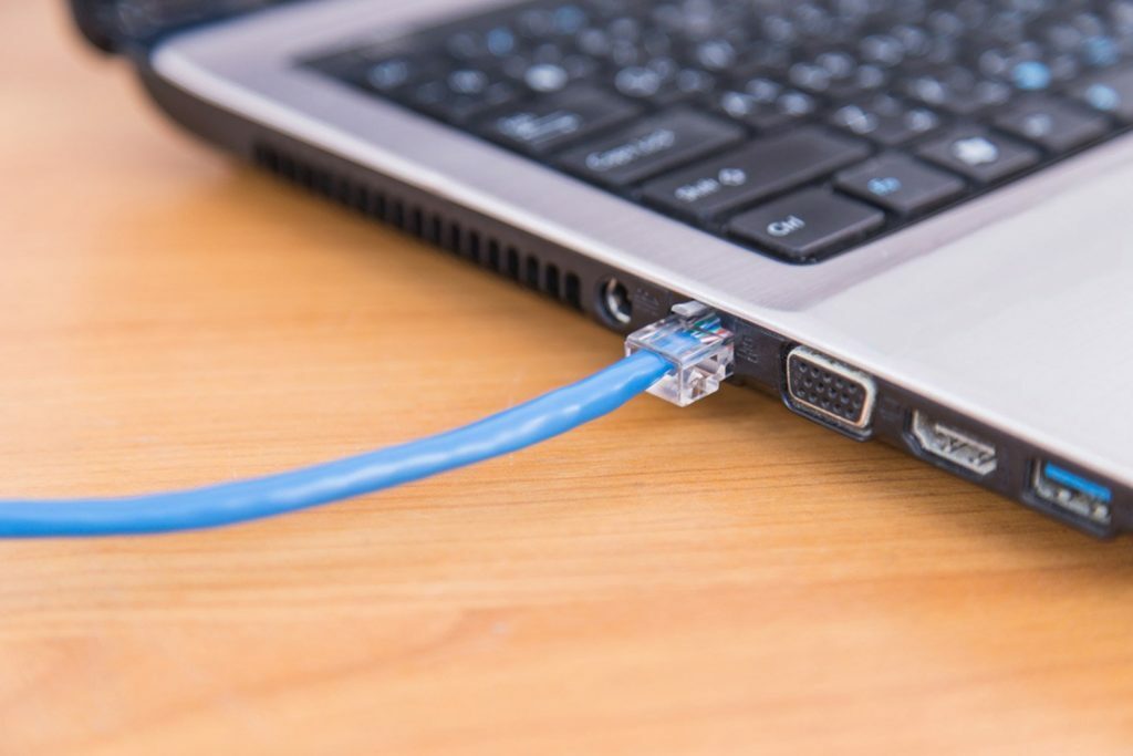
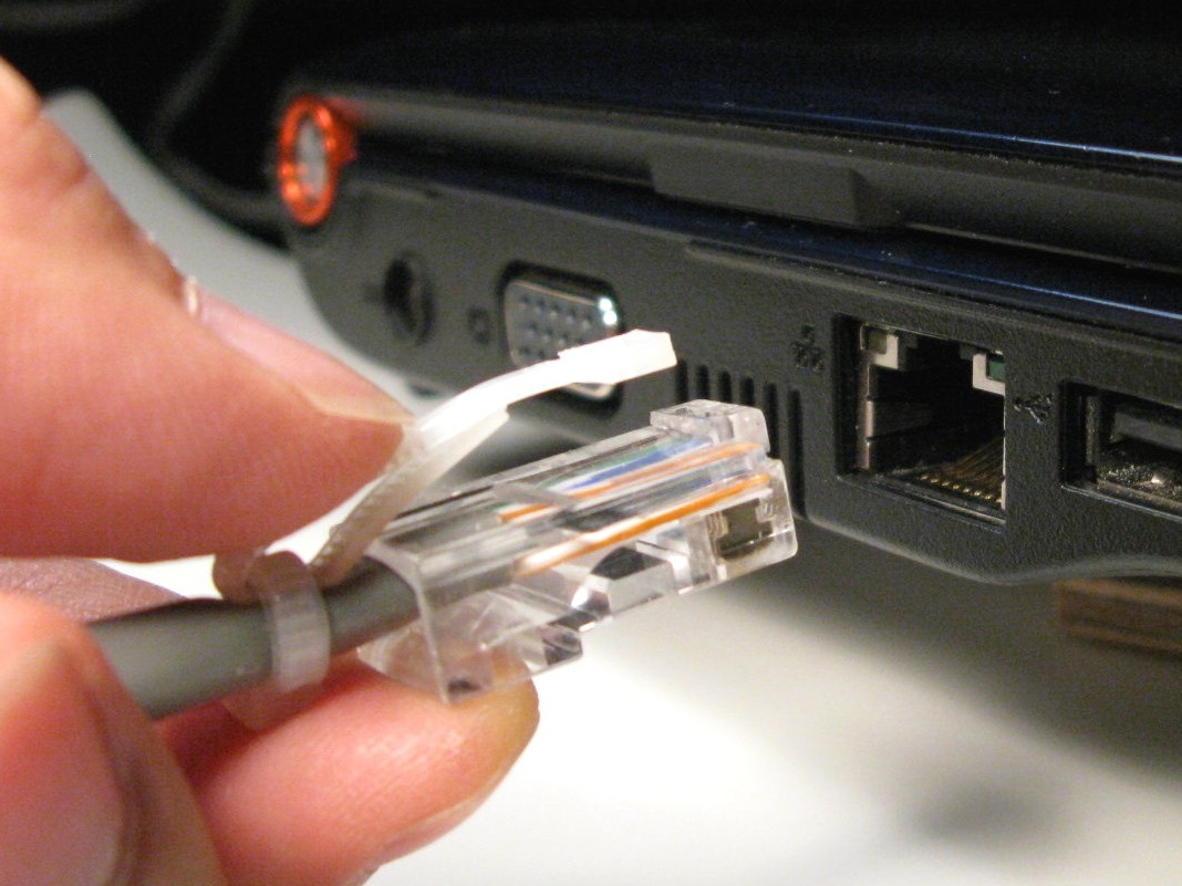
В качестве управляющего устройства мы возьмем компьютер. Для его подключения к роутеру воспользуйтесь одним из двух способов: проводным или беспроводным. В первом случае вставьте патч-корд из комплекта роутера одним концом в любой незанятный порт LAN, а другим концом в сетевое гнездо компьютера. Подключите роутер к розетке, при необходимости нажмите кнопку питания и дождитесь его загрузки. Включите в сеть компьютер и дождитесь его загрузки.
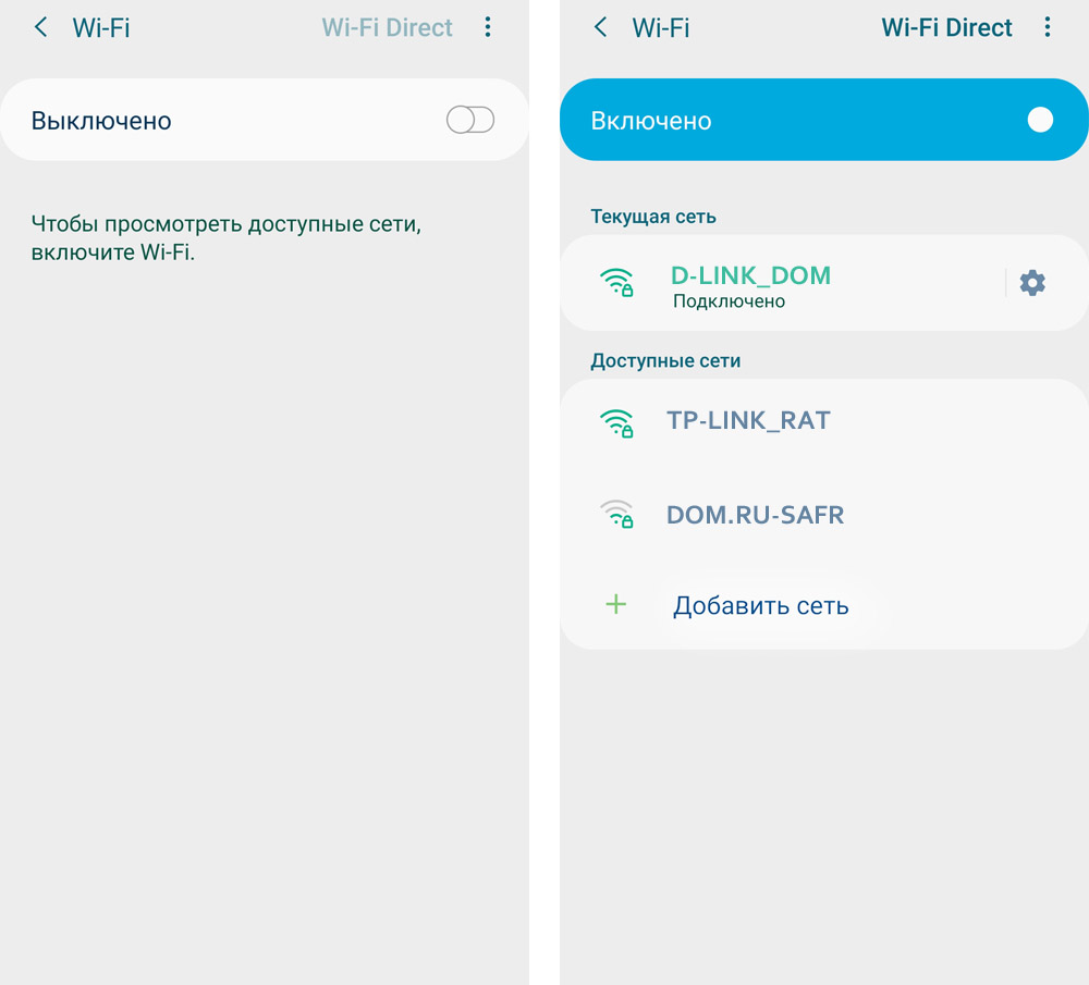
 В случае беспроводного подключения загрузите роутер и компьютер. После загрузки при необходимости включите на компьютере Wi-Fi-адаптер. На некоторых компьютерах он включается кнопкой, переключателем или комбинацией клавиш. Часто он также включен по умолчанию. После этого постройте список находящихся поблизости сетей Wi-Fi при помощи раздела сетевых подключений. На разных устройствах эта процедура выполняется по-разному. В операционной системе Windows 10 значок сетевых подключений можно найти на панели задач, в скрытых значках, в панели уведомлений или в панели управления.
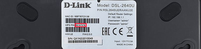
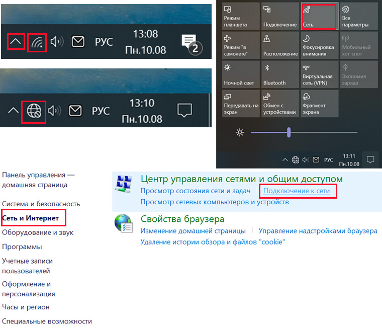 После построения списка найдите вашу сеть DSL-2640U и подключитесь к ней, используя в качестве пароля WPS PIN. Последний указан на этикетке вашего роутера в одноименной строке.
Как настроить роутер D-Link DSL-2640U
Заход в настройки D-Link DSL-2640U. Пароль по умолчанию
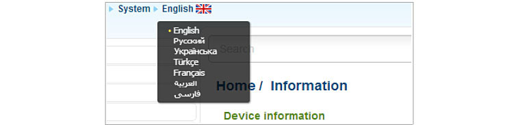
После соединения всех устройств приступим к настройкам роутера (в приведенном выше алгоритме это шаг 3). Для этого запустите на управляющем устройстве браузер и перейдите по тому IP, который указан на этикетке вашего роутера. На картинке выше это 192.168.1.1. Так вы попадаете в панель управления. Имя и пароль по умолчанию для входа в нее тоже указаны на этикетке и в нашем случае это admin и admin. При первом заходе роутер потребует сменить заводские данные, так как они не считаются надежными. Придумайте и введите новый пароль и повторите его в поле ниже. В случае открывания панели управления на иностранном языке найдите вверху слово System, разверните меню и найдите в нем свой язык.
Настройка основных параметров
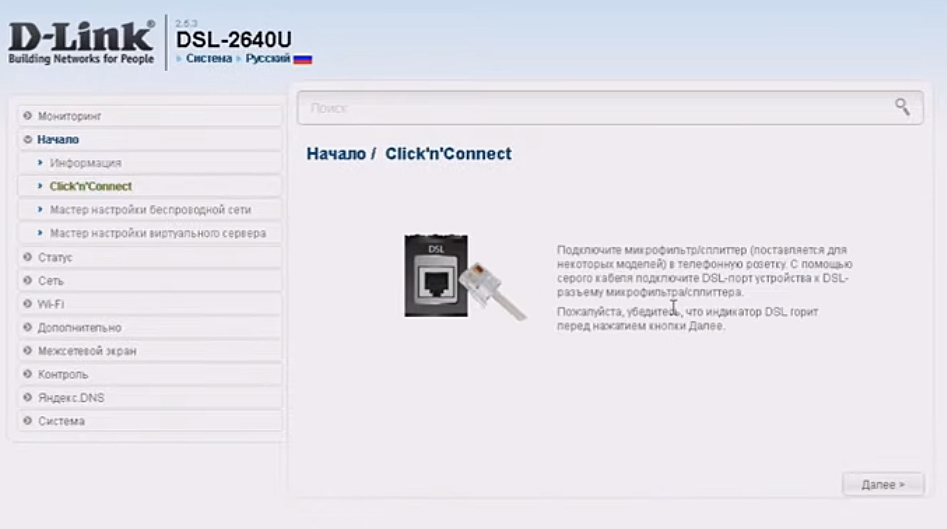
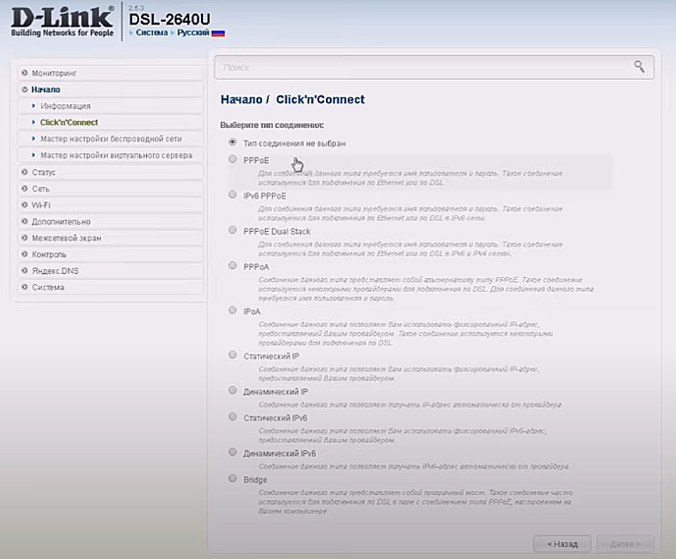
Интернет можно настраивать несколькими способами. Мы разберем вариант запуска мастера настройки. В разделе «Начало» кликните по строке Click’n Connect и в следующем окне кнопку «Далее», так как мы с вами уже подсоединили кабели.
 Дальше выберите тип соединения и задайте запрашиваемые данные. Этот пункт является наиболее сложным на всех шагах настроек и при неправильном заполнении приведет к подключению с ограничениями. Поэтому при необходимости пообщайтесь с провайдером или загляните в договор, чтобы задать точные параметры. Если тип соединения в договоре не прописан, попробуйте вариант «Динамический IP». После задания всех настроек нажмите кнопку «Применить». Сервис предложит вам перезагрузить роутер, поэтому сделайте это и дождитесь окончания перезагрузки.
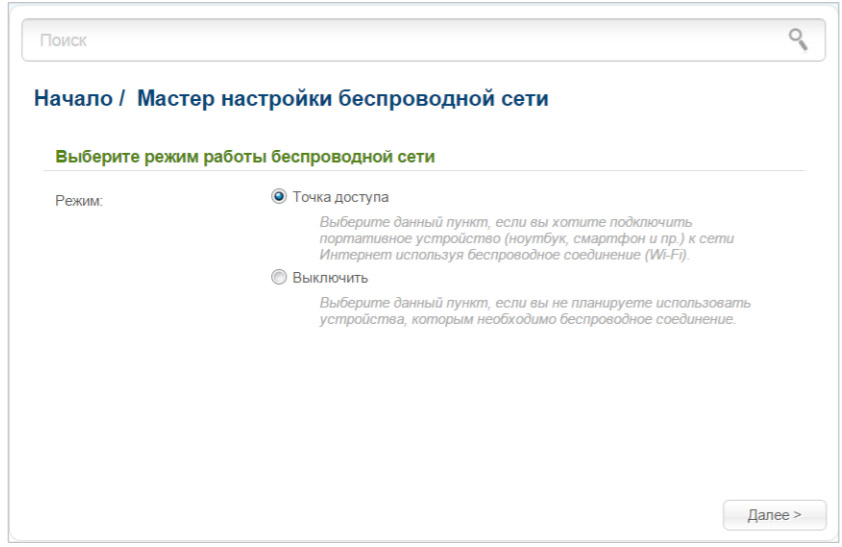
 После этого у вас должен появиться интернет. Откройте в браузере любую поисковую систему и убедитесь в этом. Но на этом настройка не завершена, так как вам нужно еще изменить параметры сети Wi-Fi. Для этого кликните в меню строку «Мастер
настройки беспроводной сети». В диалоговом окне оставьте переключатель на «Точке доступа» и нажмите «Далее».
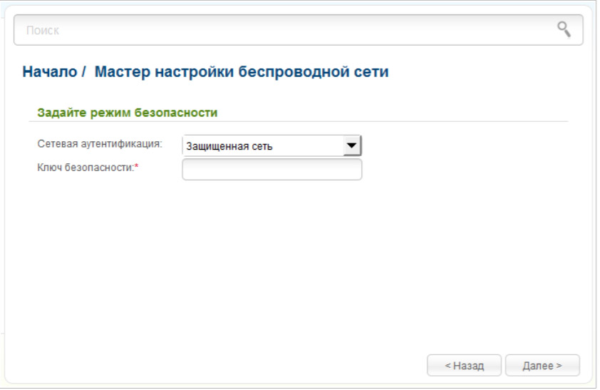
На следующем шаге придумайте SSID — имя для вашей домашней сети Wi-Fi. SSID задается латинскими буквами. Затем выберите «Защищенная сеть» и придумайте пароль для своей сети. Введите его в строку «Ключ безопасности» и нажмите «Далее» и затем «Применить».
Как подключить к роутеру другие устройства
Нам осталось рассмотреть четвертый пункт приведенного выше алгоритма подключения роутера. Домашние устройства вы можете подключить по Wi-Fi, если такой модуль имеется на устройстве, или по проводу при наличии в устройстве сетевого порта. Некоторые гаджеты могут подключаться обоими способами, поэтому выбирайте любой из них по принципу удобства. Устройства, требующие мощных ресурсов, практичнее подключать по кабелю.
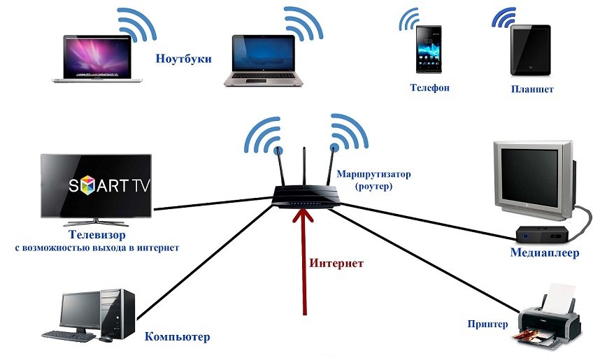
Для беспроводного подключения активируйте на подключаемом устройстве Wi-Fi, постройте список Wi-Fi-сетей и найдите в нем сеть своего роутера. Не забывайте, что на этапе настроек вы должны были сменить имя и пароль к этой сети. Подключитесь к сети, введя свой новый пароль. Для проводного подключения подготовьте патч-корд нужной длины (короткий патч-корд есть в коробке вашего роутера). Вставьте его одним концом в свободный порт LAN роутера и другим в сетевое гнездо подключаемого устройства. Зайдите в меню устройства и задайте необходимые настройки согласно договору с поставщиком услуг.
Сброс настроек роутера D-Link DSL-2640U до заводских
После сброса роутер вернется к заводским настройкам, то есть у него установится заводское название сети Wi-Fi, пароль к ней, заводские имя и пароль для входа в панель управления (они прописаны на этикетке маршрутизатора), а также сбросятся все введенные вами данные провайдера и другие настройки. Поэтому прибегайте к этой процедуре, когда потеряли пароль для входа в настройки, если роутер работает с ошибками или вы сделали неудачные настройки.

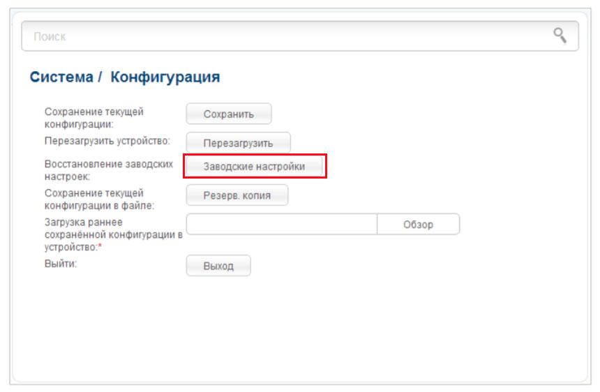
Для сброса переверните корпус роутера и найдите снизу кнопку Reset. Зажмите ее острым предметом на десять секунд и отпустите. После этого начнется возврат роутера к заводским настройкам. Если у вас нет возможности нажать кнопку, выполните сброс через панель управления. Для этого зайдите в меню «Система», выберите раздел «Конфигурация» и кликните по «Заводские настройки».
Обновление прошивки роутера D-Link DSL-2640U
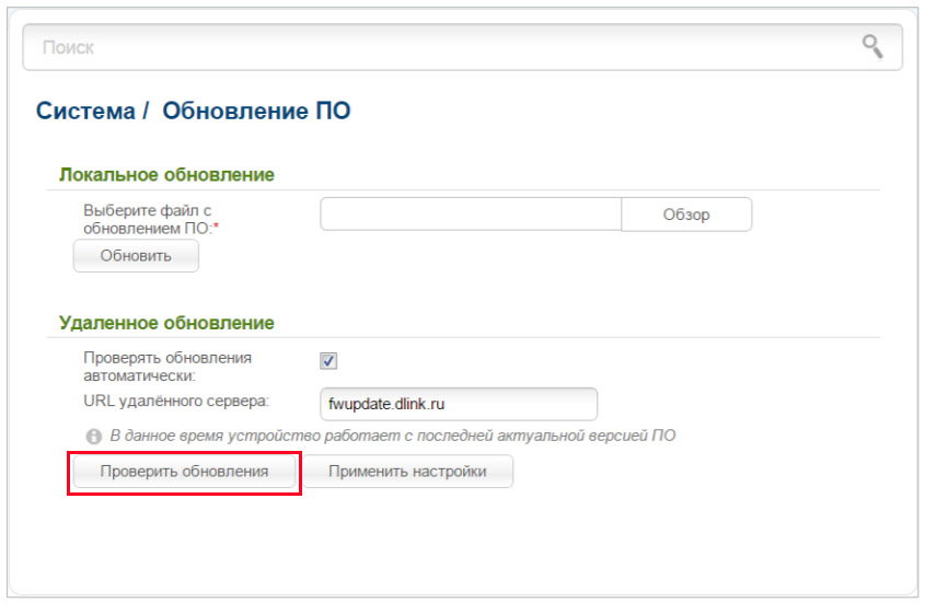
У модели DSL-2640U есть встроенная функция проверки обновлений, поэтому вам не нужно самостоятельно искать файлы новых прошивок. Когда сервис обнаружит на сайте производителя новую версию, у вас в панели управления вверху появится предупреждение об этом с предложением обновить программу. Самостоятельно проверить наличие обновлений можно в разделе «Система» и пункте «Обновление ПО». Кликните кнопку «Проверить обновления» и следуйте указаниям сервиса.
Также вы можете закачать свой файл прошивки в этом же разделе в строке «Локальное обновление». Этот пункт вам пригодится, если из-за программного сбоя роутер не хочет устанавливать обновления. Однако будьте внимательны, так как неизвестной прошивкой можно вывести роутер из строя. К этому же результату приведет и установка прошивки без учета аппаратной версии маршрутизатора. В процессе обновления прошивки нельзя выключать или перезагружать роутер, так как это может привести к его поломке. Если обновление привело к сбоям в работе роутера, нужно выполнить сброс настроек, как описано в разделе выше.
Разобравшись с основными возможностями роутера D-Link DSL-2640U, вы сможете быстро настраивать интернет на новом месте или восстанавливать его после сбоев.

-
Contents
-
Table of Contents
-
Bookmarks
Quick Links
User Manual
DSL-2640U
Wireless N 150 ADSL2+ Modem Router
June 2013
Related Manuals for D-Link DSL-2640U
Summary of Contents for D-Link DSL-2640U
-
Page 1
User Manual DSL-2640U Wireless N 150 ADSL2+ Modem Router June 2013… -
Page 2: Table Of Contents
DSL-2640U Wireless N 150 ADSL2+ Modem Router User Manual Contents Chapter 1. Introduction……….4 Contents and Audience…………4 Conventions…………..4 Document Structure…………4 Chapter 2. Overview……….5 General Information…………5 Specifications…………..6 Product Appearance…………10 Front Panel…………..10 Side Panel……………12 Back Panel……………13 Delivery Package…………14 Chapter 3. Installation and Connection……15 Before You Begin…………15…
-
Page 3
DSL-2640U Wireless N 150 ADSL2+ Modem Router User Manual Wi-Fi…………..92 Basic Settings…………92 Security Settings…………94 MAC Filter……………97 Station List………….99 WPS…………..100 Using WPS Function via Web-based Interface……102 Using WPS Function without Web-based Interface……102 Additional Settings………….104 Advanced…………..106 Interface Grouping…………107 DDNS…………..111 DNS…………..112 Routing…………..113 ADSL…………..115 Remote Access…………116… -
Page 4: Chapter 1. Introduction
Chapter 2 gives an overview of the router’s hardware and software features and describes its appearance and the package contents. Chapter 3 explains how to install the wireless router DSL-2640U and configure a PC in order to access its web-based interface.
-
Page 5: Chapter 2. Overview
In addition, any Ethernet port of the device can be used to connect to a private Ethernet line. Also DSL-2640U can operate as a base station for connecting wireless devices of the standards 802.11b, 802.11g, and 802.11n. The router supports multiple functions for the wireless interface: several security standards (WEP, WPA/WPA2), MAC address filtering, and the WPS function.
-
Page 6: Specifications
DSL-2640U Wireless N 150 ADSL2+ Modem Router Overview User Manual Specifications Interfaces ADSL: 1 RJ-11 port • LAN: 4 RJ-45 10/100BASE-TX Fast Ethernet ports with auto-MDI/MDIX • WLAN: built-in 802.11b, g, and n wireless interface • Frequency Range 2412 ~ 2484MHz •…
-
Page 7
DSL-2640U Wireless N 150 ADSL2+ Modem Router Overview User Manual ADSL Standards ADSL • ◦ Multi-mode, ANSI T1.413 Issue 2, ITU-T G.992.1 (G.dmt) Annex A, ITU-T G.992.2 (G.lite) Annex A, ITU-T G.994.1 (G.hs) ADSL2 • ◦ ITU-T G.992.3 (G.dmt.bis) Annex A/L/M, ITU-T G.992.4 (G.lite.bis) Annex A ADSL2+ •… -
Page 8
DSL-2640U Wireless N 150 ADSL2+ Modem Router Overview User Manual ATM/PPP Protocols Bridged and routed Ethernet encapsulation • VC-based or LLC-based multiplexing • ATM Forum UNI3.1/4.0 PVC (up to 8 PVCs) • ATM Adaptation Layer Type 5 (AAL5) • ITU-T I.610 OAM F4/F5 loopback •… -
Page 9
DSL-2640U Wireless N 150 ADSL2+ Modem Router Overview User Manual Interface grouping • VLAN priority (802.1p) • Configuration and Management Multilingual web-based interface for configuration and management • Access via TELNET • Firmware update via web-based interface • Saving/restoring configuration to/from file •… -
Page 10: Product Appearance
DSL-2640U Wireless N 150 ADSL2+ Modem Router Overview User Manual Product Appearance Front Panel Figure 1. Front panel view. Mode Description The router is powered on. Solid green POWER No light The router is powered off. The router is in the crash recovery mode.
-
Page 11
DSL-2640U Wireless N 150 ADSL2+ Modem Router Overview User Manual Mode Description The router’s WLAN is on. Solid green WLAN The WLAN interface is active (upstream or downstream traffic). Blinking green A device is connected to the port of the router (for the LAN port… -
Page 12: Side Panel
DSL-2640U Wireless N 150 ADSL2+ Modem Router Overview User Manual Side Panel Figure 2. Side panel view. Name Description A button to enable/disable the router’s wireless network and to quickly add wireless devices to the router’s WLAN (the WPS function).
-
Page 13: Back Panel
DSL-2640U Wireless N 150 ADSL2+ Modem Router Overview User Manual Back Panel Figure 3. Back panel view. Port Description A DSL port to connect the router to the telephone line. 4 Ethernet ports to connect Ethernet devices. One port can be used to connect to a LAN 1-4 private Ethernet line.
-
Page 14: Delivery Package
DSL-2640U Wireless N 150 ADSL2+ Modem Router Overview User Manual Delivery Package The following should be included: Wireless router DSL-2640U • Power adapter DC 12V/0.5A • RJ-11 telephone cable • Straight-through Ethernet cable (CAT 5E) • Splitter • “Quick Installation Guide” (brochure).
-
Page 15: Chapter 3. Installation And Connection
Operating System Configuration of the multifunction wireless ADSL/Ethernet router DSL-2640U (hereinafter referred to as “the router”) is performed via the built-in web-based interface. The web-based interface is available from any operating system that supports a web browser.
-
Page 16: Connecting To Pc
DSL-2640U Wireless N 150 ADSL2+ Modem Router Installation and Connection User Manual Connecting to PC PC with Ethernet Adapter 1. Make sure that your PC is powered off. 2. Connect an Ethernet cable between any of four Ethernet ports located on the back panel of the router and the Ethernet port of your PC.
-
Page 17: Obtaining Ip Address Automatically In Os Windows Xp
DSL-2640U Wireless N 150 ADSL2+ Modem Router Installation and Connection User Manual Obtaining IP Address Automatically in OS Windows XP 1. Click the Start button and proceed to the Control Panel > Network and Internet Connections > Network Connections window.
-
Page 18
DSL-2640U Wireless N 150 ADSL2+ Modem Router Installation and Connection User Manual 3. In the Local Area Connection Properties window, on the General tab, select the Internet Protocol (TCP/IP) line. Click the Properties button. Figure 5. The Local Area Connection Properties window. -
Page 19
DSL-2640U Wireless N 150 ADSL2+ Modem Router Installation and Connection User Manual 4. Select the Obtain an IP address automatically and Obtain DNS server address automatically radio buttons. Click the OK button. Figure 6. The Internet Protocol (TCP/IP) Properties window. -
Page 20: Obtaining Ip Address Automatically In Os Windows 7
DSL-2640U Wireless N 150 ADSL2+ Modem Router Installation and Connection User Manual Obtaining IP Address Automatically in OS Windows 7 1. Click the Start button and proceed to the Control Panel window. 2. Select the Network and Sharing Center section. (If the Control Panel has the category…
-
Page 21
DSL-2640U Wireless N 150 ADSL2+ Modem Router Installation and Connection User Manual 3. In the menu located on the left part of the window, select the Change adapter settings line. Figure 8. The Network and Sharing Center window. Page 21 of 149… -
Page 22
DSL-2640U Wireless N 150 ADSL2+ Modem Router Installation and Connection User Manual 4. In the opened window, right-click the relevant Local Area Connection icon and select the Properties line in the menu displayed. Figure 9. The Network Connections window. Page 22 of 149… -
Page 23
DSL-2640U Wireless N 150 ADSL2+ Modem Router Installation and Connection User Manual 5. In the Local Area Connection Properties window, on the Networking tab, select the Internet Protocol Version 4 (TCP/IPv4) line. Click the Properties button. Figure 10. The Local Area Connection Properties window. -
Page 24
DSL-2640U Wireless N 150 ADSL2+ Modem Router Installation and Connection User Manual 6. Select the Obtain an IP address automatically and Obtain DNS server address automatically radio buttons. Click the OK button. Figure 11. The Internet Protocol Version 4 (TCP/IPv4) Properties window. -
Page 25: Pc With Wi-Fi Adapter
DSL-2640U Wireless N 150 ADSL2+ Modem Router Installation and Connection User Manual PC with Wi-Fi Adapter 1. To connect the router to a DSL line: connect a phone cable between the DSL port of the router and the ADSL OUT port of the splitter. Connect your phone to the PHONE port of the splitter.
-
Page 26: Configuring Wi-Fi Adapter In Os Windows Xp
DSL-2640U Wireless N 150 ADSL2+ Modem Router Installation and Connection User Manual Configuring Wi-Fi Adapter in OS Windows XP 1. Click the Start button and proceed to the Control Panel > Network and Internet Connections > Network Connections window. 2. Select the icon of the wireless network connection and make sure that your Wi-Fi adapter is Figure 12.
-
Page 27: Configuring Wi-Fi Adapter In Os Windows 7
DSL-2640U Wireless N 150 ADSL2+ Modem Router Installation and Connection User Manual Configuring Wi-Fi Adapter in OS Windows 7 1. Click the Start button and proceed to the Control Panel window. 2. Select the Network and Sharing Center section. (If the Control Panel has the category…
-
Page 28
DSL-2640U Wireless N 150 ADSL2+ Modem Router Installation and Connection User Manual 6. In the opened window, in the list of available wireless networks, select the wireless network DSL-2640U and click the Connect button. Figure 15. The list of available networks. -
Page 29: Connecting To Web-Based Interface
2. In the address bar of the web browser, enter the IP address of the router (by default, the following IP address is specified: 192.168.1.1). Press the Enter key. Figure 16. Connecting to the web-based interface of the DSL-2640U device. 3. On the opened page, enter the username and password for the administrator account in the Login and Password fields correspondingly (by default, the following username and password are specified: admin, admin).
-
Page 30: Web-Based Interface Structure
DSL-2640U Wireless N 150 ADSL2+ Modem Router Installation and Connection User Manual Web-based Interface Structure After successful registration the router’s quick settings page opens. Figure 18. The quick settings page. The web-based interface of the router is multilingual. Select a needed language from the menu displayed when the mouse pointer is over the Language caption.
-
Page 31
DSL-2640U Wireless N 150 ADSL2+ Modem Router Installation and Connection User Manual On the quick settings page you can run a needed Wizard, quickly get to some pages of the web- based interface, search for a specific page, or switch to the advanced settings section. -
Page 32
DSL-2640U Wireless N 150 ADSL2+ Modem Router Installation and Connection User Manual Figure 20. The advanced settings page. The pages of the Status section display data on the current state of the router (for the description of the pages, see the Status section, page 69). -
Page 33: Saving And Restoring Settings
DSL-2640U Wireless N 150 ADSL2+ Modem Router Installation and Connection User Manual Also you can find a specific page via search. To do this, enter the name of the page, wholly or partly, in the search bar in the top part of the web-based interface page, and then select a needed link in the search results.
-
Page 34
DSL-2640U Wireless N 150 ADSL2+ Modem Router Installation and Connection User Manual Figure 23. The top-page menu. Click the Reboot line if you have already saved the router’s settings. Click the Save&Reboot line to save new settings and immediately reboot the router. -
Page 35: Chapter 4. Configuring Via Web-Based Interface
DSL-2640U Wireless N 150 ADSL2+ Modem Router Configuring via Web-based Interface User Manual CHAPTER 4. CONFIGURING WEB-BASED INTERFACE Click’n’Connect To configure a WAN connection, click the Click’n’Connect link in the Net section. Figure 24. Configuring a WAN connection. Connect a phone or Ethernet cable to the router (see the Connecting to PC section, page 16).
-
Page 36
DSL-2640U Wireless N 150 ADSL2+ Modem Router Configuring via Web-based Interface User Manual Figure 25. The page for selecting the connection type. On the opened page, select the needed choice of the radio button and click the Next button. Figure 26. The page for selecting a port or interface. -
Page 37: Creating Wan Connection
DSL-2640U Wireless N 150 ADSL2+ Modem Router Configuring via Web-based Interface User Manual Creating WAN Connection PPPoE or PPPoA Connection Figure 27. Configuring PPPoE WAN connection. In the Connection name field, specify a name for the connection for easier identification.
-
Page 38
DSL-2640U Wireless N 150 ADSL2+ Modem Router Configuring via Web-based Interface User Manual Figure 28. Configuring PPPoE WAN connection. The expert settings mode. The ATM section. Parameter Description Connection name A name for connection for easier identification. Virtual Path Identifier. -
Page 39
DSL-2640U Wireless N 150 ADSL2+ Modem Router Configuring via Web-based Interface User Manual Parameter Description the Peak Cell Rate field is displayed. Specify a required value (in cells per second). (Constant Bit Rate): This service is used for applications that require a constant data rate. -
Page 40
DSL-2640U Wireless N 150 ADSL2+ Modem Router Configuring via Web-based Interface User Manual Figure 29. Configuring PPPoE WAN connection. The expert settings mode. The Ethernet section. Parameter Description Ethernet The maximum size of units transmitted by the interface. A MAC address assigned to the interface. This parameter is mandatory if your ISP uses MAC address binding. -
Page 41
DSL-2640U Wireless N 150 ADSL2+ Modem Router Configuring via Web-based Interface User Manual Figure 30. Configuring PPPoE WAN connection. The expert settings mode. The PPP section. Parameter Description Username A username (login) to access the Internet. Select the checkbox if you don’t need to enter a username and Without authorization password to access the Internet. -
Page 42: Static Ip Address
DSL-2640U Wireless N 150 ADSL2+ Modem Router Configuring via Web-based Interface User Manual Parameter Description Select the checkbox if you want the router to establish connection to the Internet on demand. In the Maximum idle time field, specify a Dial on demand period of inactivity (in seconds) after which the connection should be terminated.
-
Page 43
DSL-2640U Wireless N 150 ADSL2+ Modem Router Configuring via Web-based Interface User Manual Parameter Description Miscellaneous Select the checkbox to allow multicast traffic from the external Enable IGMP Multicast network (e.g. video streaming) to be received. Select the checkbox if you want one WAN IP address to be used for all computers of your LAN. -
Page 44: Ipoa Or Static Ip Connection
DSL-2640U Wireless N 150 ADSL2+ Modem Router Configuring via Web-based Interface User Manual IPoA or Static IP Connection Figure 32. Configuring Static IP WAN connection. In the Connection name field, specify a name for the connection for easier identification. For ADSL WAN connection, fill in the VPI and VCI fields.
-
Page 45
DSL-2640U Wireless N 150 ADSL2+ Modem Router Configuring via Web-based Interface User Manual Figure 33. Configuring Static IP WAN connection. The expert settings mode. The ATM and IP sections. Parameter Description Connection name A name for connection for easier identification. -
Page 46
DSL-2640U Wireless N 150 ADSL2+ Modem Router Configuring via Web-based Interface User Manual Parameter Description the Peak Cell Rate field is displayed. Specify a required value (in cells per second). (Constant Bit Rate): This service is used for applications that require a constant data rate. -
Page 47
DSL-2640U Wireless N 150 ADSL2+ Modem Router Configuring via Web-based Interface User Manual Figure 34. Configuring Static IP WAN connection. The expert settings mode. The Ethernet section. Parameter Description Ethernet The maximum size of units transmitted by the interface. A MAC address assigned to the interface. This parameter is mandatory if your ISP uses MAC address binding. -
Page 48
DSL-2640U Wireless N 150 ADSL2+ Modem Router Configuring via Web-based Interface User Manual Figure 35. Configuring Static IP WAN connection. The expert settings mode. The Miscellaneous and VLAN sections. Parameter Description Miscellaneous Select the checkbox to allow multicast traffic from the external Enable IGMP Multicast network (e.g. -
Page 49
DSL-2640U Wireless N 150 ADSL2+ Modem Router Configuring via Web-based Interface User Manual Parameter Description A priority tag for the type of traffic transmitted. The field is VLAN priority displayed when the Use VLAN checkbox is selected. Click the Next button to continue. -
Page 50: Dynamic Ip Connection
DSL-2640U Wireless N 150 ADSL2+ Modem Router Configuring via Web-based Interface User Manual Dynamic IP Connection Figure 36. Configuring Dynamic IP WAN connection. In the Connection name field, specify a name for the connection for easier identification. For ADSL WAN connection, fill in the VPI and VCI fields.
-
Page 51
DSL-2640U Wireless N 150 ADSL2+ Modem Router Configuring via Web-based Interface User Manual Figure 37. Configuring Dynamic IP WAN connection. The expert settings mode. The ATM and IP sections. Parameter Description Connection name A name for connection for easier identification. -
Page 52
DSL-2640U Wireless N 150 ADSL2+ Modem Router Configuring via Web-based Interface User Manual Parameter Description the Peak Cell Rate field is displayed. Specify a required value (in cells per second). (Constant Bit Rate): This service is used for applications that require a constant data rate. -
Page 53
DSL-2640U Wireless N 150 ADSL2+ Modem Router Configuring via Web-based Interface User Manual Figure 38. Configuring Dynamic IP WAN connection. The expert settings mode. The Ethernet section. Parameter Description Ethernet The maximum size of units transmitted by the interface. A MAC address assigned to the interface. This parameter is mandatory if your ISP uses MAC address binding. -
Page 54
DSL-2640U Wireless N 150 ADSL2+ Modem Router Configuring via Web-based Interface User Manual Figure 39. Configuring Dynamic IP WAN connection. The expert settings mode. The Miscellaneous and VLAN sections. Parameter Description Miscellaneous Select the checkbox to allow multicast traffic from the external Enable IGMP Multicast network (e.g. -
Page 55
DSL-2640U Wireless N 150 ADSL2+ Modem Router Configuring via Web-based Interface User Manual Parameter Description A priority tag for the type of traffic transmitted. The field is VLAN priority displayed when the Use VLAN checkbox is selected. Click the Next button to continue. -
Page 56: Bridge Connection
DSL-2640U Wireless N 150 ADSL2+ Modem Router Configuring via Web-based Interface User Manual Bridge Connection Figure 40. Configuring Bridge WAN connection. In the Connection name field, specify a name for the connection for easier identification. For ADSL WAN connection, fill in the VPI and VCI fields.
-
Page 57
DSL-2640U Wireless N 150 ADSL2+ Modem Router Configuring via Web-based Interface User Manual Figure 41. Configuring Bridge WAN connection. The expert settings mode. The ATM and VLAN sections. Parameter Description Connection name A name for connection for easier identification. Virtual Path Identifier. -
Page 58
DSL-2640U Wireless N 150 ADSL2+ Modem Router Configuring via Web-based Interface User Manual Parameter Description the Peak Cell Rate field is displayed. Specify a required value (in cells per second). (Constant Bit Rate): This service is used for applications that require a constant data rate. -
Page 59
DSL-2640U Wireless N 150 ADSL2+ Modem Router Configuring via Web-based Interface User Manual Figure 42. Configuring Bridge WAN connection. The expert settings mode. The Ethernet section. Parameter Description Ethernet The maximum size of units transmitted by the interface. A MAC address assigned to the interface. This parameter is mandatory if your ISP uses MAC address binding. -
Page 60: Checking Internet Availability
DSL-2640U Wireless N 150 ADSL2+ Modem Router Configuring via Web-based Interface User Manual Checking Internet Availability On the page, you can check the WAN connection you have created. Figure 43. Checking the Internet availability. In the Result section, the status of the WAN connection and possible causes of malfunctions are displayed.
-
Page 61: Configuring Wireless Connection
DSL-2640U Wireless N 150 ADSL2+ Modem Router Configuring via Web-based Interface User Manual Configuring Wireless Connection Figure 44. The page for selecting the operating mode for the wireless network. If you are not going to use the wireless connection, select the Turn off choice of the Mode radio button.
-
Page 62
DSL-2640U Wireless N 150 ADSL2+ Modem Router Configuring via Web-based Interface User Manual On the opened page, in the SSID field, specify a new name for the network (use digits and Latin characters). Figure 45. Page for changing the name of the wireless LAN. -
Page 63
DSL-2640U Wireless N 150 ADSL2+ Modem Router Configuring via Web-based Interface User Manual On the next page, you can modify security settings of the WLAN. The default security settings do not provide sufficient protection for the WLAN. Please, specify your own security settings for the WLAN. -
Page 64: Wireless Network Settings Wizard
DSL-2640U Wireless N 150 ADSL2+ Modem Router Configuring via Web-based Interface User Manual Wireless Network Settings Wizard To specify all needed settings for your wireless network, click the Wireless network settings wizard in the Wi-Fi section. Figure 47. The page for selecting the operating mode for the wireless network.
-
Page 65
DSL-2640U Wireless N 150 ADSL2+ Modem Router Configuring via Web-based Interface User Manual On the opened page, in the SSID field, specify a new name for the network (use digits and Latin characters). Figure 48. Page for changing the name of the wireless LAN. -
Page 66
DSL-2640U Wireless N 150 ADSL2+ Modem Router Configuring via Web-based Interface User Manual On the next page, you can modify security settings of the WLAN. The default security settings do not provide sufficient protection for the WLAN. Please, specify your own security settings for the WLAN. -
Page 67: Virtual Server Settings Wizard
DSL-2640U Wireless N 150 ADSL2+ Modem Router Configuring via Web-based Interface User Manual Virtual Server Settings Wizard To create a virtual server for redirecting incoming Internet traffic to a specified IP address in the LAN, click the Virtual server settings wizard link in the Firewall section.
-
Page 68
DSL-2640U Wireless N 150 ADSL2+ Modem Router Configuring via Web-based Interface User Manual Parameter Description Enter the IP address of the server from the local area network. To Private port (begin)/ choose a device connected to the router’s LAN at the moment, select… -
Page 69: Status
DSL-2640U Wireless N 150 ADSL2+ Modem Router Configuring via Web-based Interface User Manual Status The pages of this section display data on the current state of the router: network statistics • DSL connection status • active WAN connections • IP addresses leased by the DHCP server •…
-
Page 70: Dsl Status
DSL-2640U Wireless N 150 ADSL2+ Modem Router Configuring via Web-based Interface User Manual DSL Status The information shown on the tabs of the Status / DSL status page can be used for troubleshooting and diagnosing connection problems. Figure 52. The Status / DSL status page.
-
Page 71: Wan Status
DSL-2640U Wireless N 150 ADSL2+ Modem Router Configuring via Web-based Interface User Manual WAN Status The Status / WAN status page displays active WAN connections. Figure 53. The Status / WAN status page. Page 71 of 149…
-
Page 72: Dhcp
DSL-2640U Wireless N 150 ADSL2+ Modem Router Configuring via Web-based Interface User Manual DHCP The Status / DHCP page displays the information on computers that have been identified by hostnames and MAC addresses and have got IP addresses from the DHCP server of the device, as well as the IP address expiration periods (the lease time).
-
Page 73: Routing Table
DSL-2640U Wireless N 150 ADSL2+ Modem Router Configuring via Web-based Interface User Manual Routing Table The Status / Routing table page displays the information on routes. The table contains destination IP addresses, gateways, subnet masks, and other data. Figure 55. The Status / Routing table page.
-
Page 74: Clients
DSL-2640U Wireless N 150 ADSL2+ Modem Router Configuring via Web-based Interface User Manual Clients On the Status / Clients page, you can view the list of devices connected to the router and devices accessing its web-based interface. Figure 56. The Status / Clients page.
-
Page 75: Net
DSL-2640U Wireless N 150 ADSL2+ Modem Router Configuring via Web-based Interface User Manual In this menu you can configure basic parameters of the router’s local area network and configure connection to the Internet (a WAN connection). On the Net / WAN page, you can create and edit connections used by the router.
-
Page 76: Creating Adsl Wan Connection
DSL-2640U Wireless N 150 ADSL2+ Modem Router Configuring via Web-based Interface User Manual Creating ADSL WAN Connection Figure 58. The page for creating a new connection. The General settings and ATM sections. Parameter Description General settings A type of network protocol to be used by the connection. Available…
-
Page 77
DSL-2640U Wireless N 150 ADSL2+ Modem Router Configuring via Web-based Interface User Manual Parameter Description Direction The direction of this connection. Virtual Path Identifier. The valid range is from 0 to 250. Virtual Circuit Identifier. The valid range is from 32 to 65535. -
Page 78
DSL-2640U Wireless N 150 ADSL2+ Modem Router Configuring via Web-based Interface User Manual Parameter Description Realtime VBR (Real-time Variable Bit Rate): This service is used for delay- sensitive applications such as real time video. The Rt-VBR provides higher network flexibility than the CBR service. When you select… -
Page 79
DSL-2640U Wireless N 150 ADSL2+ Modem Router Configuring via Web-based Interface User Manual Parameter Description A priority tag for the type of traffic transmitted. The field is VLAN priority displayed when the Use VLAN checkbox is selected. The Miscellaneous section is displayed for all connection types except for Bridge. -
Page 80
DSL-2640U Wireless N 150 ADSL2+ Modem Router Configuring via Web-based Interface User Manual The PPP section is displayed for the PPPoE and PPPoA connection types. Figure 61. The page for creating a new connection. The PPP section. Parameter Description Username A username (login) to access the Internet. -
Page 81
DSL-2640U Wireless N 150 ADSL2+ Modem Router Configuring via Web-based Interface User Manual Parameter Description Select the checkbox if you want the router to establish connection to the Internet on demand. In the Maximum idle time field, specify a Dial on demand period of inactivity (in seconds) after which the connection should be terminated. -
Page 82
DSL-2640U Wireless N 150 ADSL2+ Modem Router Configuring via Web-based Interface User Manual Parameter Description Displayed for the Static IP and IPoA types only. IP Address Enter an IP address for this WAN connection. Displayed for the Static IP and IPoA types only. -
Page 83: Creating Ethernet Wan Connection
DSL-2640U Wireless N 150 ADSL2+ Modem Router Configuring via Web-based Interface User Manual Creating Ethernet WAN Connection Prior to creating an Ethernet WAN connection, specify a LAN port that will be used as the WAN port (see the Interface Grouping section, page 107).
-
Page 84
DSL-2640U Wireless N 150 ADSL2+ Modem Router Configuring via Web-based Interface User Manual Parameter Description Ethernet The maximum size of units transmitted by the interface. A MAC address assigned to the interface. This parameter is mandatory if your ISP uses MAC address binding. In the field, enter the MAC address registered by your ISP upon concluding the agreement. -
Page 85
DSL-2640U Wireless N 150 ADSL2+ Modem Router Configuring via Web-based Interface User Manual The Miscellaneous section is displayed for all connection types except for Bridge. Figure 64. The page for creating a new connection. The Miscellaneous section. Parameter Description Miscellaneous… -
Page 86
DSL-2640U Wireless N 150 ADSL2+ Modem Router Configuring via Web-based Interface User Manual The PPP section is displayed for the PPPoE connection type. Figure 65. The page for creating a new connection. The PPP section. Parameter Description Username A username (login) to access the Internet. -
Page 87
DSL-2640U Wireless N 150 ADSL2+ Modem Router Configuring via Web-based Interface User Manual Parameter Description Select the checkbox if you want the router to establish connection to the Internet on demand. In the Maximum idle time field, specify a Dial on demand period of inactivity (in seconds) after which the connection should be terminated. -
Page 88
DSL-2640U Wireless N 150 ADSL2+ Modem Router Configuring via Web-based Interface User Manual Parameter Description Displayed for the Static IP type only. IP Address Enter an IP address for this WAN connection. Displayed for the Static IP type only. Netmask Enter a subnet mask for this WAN connection. -
Page 89: Lan
DSL-2640U Wireless N 150 ADSL2+ Modem Router Configuring via Web-based Interface User Manual To configure the router’s local interface, proceed to the Net / LAN page. Figure 67. Basic settings of the local interface. If needed, edit the basic parameters of the local interface.
-
Page 90
DSL-2640U Wireless N 150 ADSL2+ Modem Router Configuring via Web-based Interface User Manual In the DHCP server section, you can configure the built-in DHCP server of the router. The built-in DHCP server automatically assigns IP addresses to computers of the main local subnet (you need to specify IP addresses manually for computers of the additional local subnet). -
Page 91
DSL-2640U Wireless N 150 ADSL2+ Modem Router Configuring via Web-based Interface User Manual When all needed settings are configured, click the Save button. In the Static DHCP section, you can specify MAC address and IP address pairs (set a fixed IP address in the local area network for a device with a certain MAC address). -
Page 92: Wi-Fi
DSL-2640U Wireless N 150 ADSL2+ Modem Router Configuring via Web-based Interface User Manual Wi-Fi In this menu you can specify all needed settings for your wireless network. Basic Settings On the Wi-Fi / Basic settings page, you can enable your wireless local area network (WLAN) and configure its basic parameters.
-
Page 93
(It is recommended not to select this checkbox in order to simplify initial configuration of your WLAN.) A name for the WLAN. By default, the value DSL-2640U is SSID specified. It is recommended to specify another name for the network upon initial configuration (use digits and Latin characters). -
Page 94: Security Settings
DSL-2640U Wireless N 150 ADSL2+ Modem Router Configuring via Web-based Interface User Manual Security Settings On the Wi-Fi / Security settings page, you can modify security settings of the WLAN. Figure 72. The default security settings. By default, the Open network authentication type with no encryption is specified for the WLAN.
-
Page 95
DSL-2640U Wireless N 150 ADSL2+ Modem Router Configuring via Web-based Interface User Manual When the Open value is selected, the WEP Encryption settings section is displayed: Figure 73. The Open value is selected from the Network Authentication drop-down list. Parameter Description The checkbox activating WEP encryption. -
Page 96
DSL-2640U Wireless N 150 ADSL2+ Modem Router Configuring via Web-based Interface User Manual When the WPA-PSK or WPA2-PSK value is selected, the WPA Encryption settings section is displayed: Figure 74. The WPA2-PSK value is selected from the Network Authentication drop-down list. -
Page 97: Mac Filter
DSL-2640U Wireless N 150 ADSL2+ Modem Router Configuring via Web-based Interface User Manual MAC Filter On the Wi-Fi / MAC Filter page, you can define a set of MAC addresses of devices which will be allowed to access the WLAN, or define MAC addresses of devices which will not be allowed to access the WLAN.
-
Page 98
DSL-2640U Wireless N 150 ADSL2+ Modem Router Configuring via Web-based Interface User Manual Figure 76. The tab for adding a MAC address. Click the Add button and enter an address in the field displayed. Also you can enter the MAC address of a device connected to the router’s LAN at the moment. -
Page 99: Station List
DSL-2640U Wireless N 150 ADSL2+ Modem Router Configuring via Web-based Interface User Manual Station List On the Wi-Fi / Station List page, you can view the list of wireless clients connected to the router. Figure 77. The list of the router’s wireless clients.
-
Page 100: Wps
DSL-2640U Wireless N 150 ADSL2+ Modem Router Configuring via Web-based Interface User Manual On the Wi-Fi / WPS page, you can enable the function for secure configuration of the WLAN and select a method used to easily add wireless devices to the WLAN.
-
Page 101
DSL-2640U Wireless N 150 ADSL2+ Modem Router Configuring via Web-based Interface User Manual To activate the WPS function, select the WPS Enable checkbox and click the Change button. When the checkbox is selected, the Information and Connection sections are available on the page. -
Page 102: Using Wps Function Via Web-Based Interface
DSL-2640U Wireless N 150 ADSL2+ Modem Router Configuring via Web-based Interface User Manual Using WPS Function via Web-based Interface To add a wireless device via the PIN method of the WPS function, follow the next steps: 1. Select the WPS Enable checkbox.
-
Page 103
DSL-2640U Wireless N 150 ADSL2+ Modem Router Configuring via Web-based Interface User Manual Later you will be able to add wireless devices to the WLAN by pressing the WPS/WLAN button of the router. 1. Select the PBC method in the software of the wireless device that you want to connect to the router’s WLAN. -
Page 104: Additional Settings
DSL-2640U Wireless N 150 ADSL2+ Modem Router Configuring via Web-based Interface User Manual Additional Settings On the Wi-Fi / Additional settings page, you can define additional parameters for the router’s WLAN. Changing parameters presented on this page may negatively affect your WLAN! Figure 79.
-
Page 105
DSL-2640U Wireless N 150 ADSL2+ Modem Router Configuring via Web-based Interface User Manual The following fields are available on the page: Parameter Description The time interval (in milliseconds) between packets sent to synchronize Beacon Period the wireless network. The minimum size (in bites) of a packet for which an RTS frame is RTS Threshold transmitted. -
Page 106: Advanced
DSL-2640U Wireless N 150 ADSL2+ Modem Router Configuring via Web-based Interface User Manual Advanced In this menu you can configure advanced settings of the router: define interface groups and allow the router to connect to a private Ethernet line •…
-
Page 107: Interface Grouping
DSL-2640U Wireless N 150 ADSL2+ Modem Router Configuring via Web-based Interface User Manual Interface Grouping On the Advanced / Interface grouping page, you can assign virtual PVC connections to the router’s ports (create groups of interfaces), which allows distinguishing different types of traffic.
-
Page 108
DSL-2640U Wireless N 150 ADSL2+ Modem Router Configuring via Web-based Interface User Manual To change the operating parameters of a LAN port of the router, place the mouse pointer on the relevant LAN port and click the Setup speed and stream line in the menu displayed (the line is not available if the LAN port is used as the WAN port). -
Page 109
DSL-2640U Wireless N 150 ADSL2+ Modem Router Configuring via Web-based Interface User Manual To enable the Ethernet WAN function, follow the steps below. 1. Place the mouse pointer on the router’s LAN port that will be used as the WAN port and click the Make WAN line in the menu displayed. -
Page 110
DSL-2640U Wireless N 150 ADSL2+ Modem Router Configuring via Web-based Interface User Manual You can specify the following parameters: Parameter Description A name for the group for easier identification. You can specify any Name name. The list of available internal interfaces is displayed in the left drop- down list. -
Page 111: Ddns
DSL-2640U Wireless N 150 ADSL2+ Modem Router Configuring via Web-based Interface User Manual DDNS On the Advanced / DDNS page, you can define parameters of the DDNS service, which allows associating a domain name with dynamic IP addresses. Figure 83. The Advanced / DDNS page.
-
Page 112: Dns
DSL-2640U Wireless N 150 ADSL2+ Modem Router Configuring via Web-based Interface User Manual On the Advanced / DNS page, you can add DNS servers to the system. Figure 84. The Advanced / DNS page. DNS servers are used to determine the IP address from the name of a server in Intranets or the Internet (as a rule, they are specified by an ISP or assigned by a network administrator).
-
Page 113: Routing
DSL-2640U Wireless N 150 ADSL2+ Modem Router Configuring via Web-based Interface User Manual Routing On the Advanced / Routing page, you can add static routes (routes for networks that are not connected directly to the device but are available through the interfaces of the device) into the system.
-
Page 114
DSL-2640U Wireless N 150 ADSL2+ Modem Router Configuring via Web-based Interface User Manual To edit an existing route, select a needed field in the relevant line of the table, change its value, and click the Save button. To remove an existing route, select the checkbox located to the left of the relevant line in the table and click the Save button. -
Page 115: Adsl
DSL-2640U Wireless N 150 ADSL2+ Modem Router Configuring via Web-based Interface User Manual ADSL The Advanced / ADSL page includes the set of ADSL standards that should be defined by an ISP. Contact your ISP to set proper parameters. Select the relevant options and click the Change button.
-
Page 116: Remote Access
DSL-2640U Wireless N 150 ADSL2+ Modem Router Configuring via Web-based Interface User Manual Remote Access On the Advanced / Remote access page, you can configure remote access to the web-based interface of the router. By default, the access from external networks to the router is closed. If you need to allow access to the router from the external network, create relevant rules.
-
Page 117
DSL-2640U Wireless N 150 ADSL2+ Modem Router Configuring via Web-based Interface User Manual To edit a rule for remote access, select a needed field in the relevant line of the table, change its value, and click the Save button. To remove a rule for remote access, select the checkbox located to the left of the relevant line in the table and click the Save button. -
Page 118: Firewall
DSL-2640U Wireless N 150 ADSL2+ Modem Router Configuring via Web-based Interface User Manual Firewall In this menu you can configure the firewall of the router: add rules for IP filtering • create virtual servers • define a DMZ • configure the Port Triggering function •…
-
Page 119
DSL-2640U Wireless N 150 ADSL2+ Modem Router Configuring via Web-based Interface User Manual Figure 89. The page for adding a rule for IP filtering. You can specify the following parameters: Parameter Description General Name A name for the rule for easier identification. -
Page 120
DSL-2640U Wireless N 150 ADSL2+ Modem Router Configuring via Web-based Interface User Manual Parameter Description The source host/subnet IP address. To choose a device connected to the router’s LAN at the moment, select the relevant IP address from the drop-down list (the field will be filled in automatically). -
Page 121: Virtual Servers
DSL-2640U Wireless N 150 ADSL2+ Modem Router Configuring via Web-based Interface User Manual Virtual Servers On the Firewall / Virtual servers page, you can create virtual servers for redirecting incoming Internet traffic to a specified IP address in the local area network.
-
Page 122
DSL-2640U Wireless N 150 ADSL2+ Modem Router Configuring via Web-based Interface User Manual Figure 91. The page for adding a virtual server. You can specify the following parameters: Parameter Description Select a virtual server template from the drop-down list, or select… -
Page 123
DSL-2640U Wireless N 150 ADSL2+ Modem Router Configuring via Web-based Interface User Manual Parameter Description The IP address of the server from the local area network. To choose a device connected to the router’s LAN at the moment, select the… -
Page 124: Dmz
DSL-2640U Wireless N 150 ADSL2+ Modem Router Configuring via Web-based Interface User Manual A DMZ is a host or network segment located “between” internal (local) and external (global) networks. In the router, the DMZ implements the capability to transfer a request coming to a port of the DSL router from the external network to a specified host of the internal network.
-
Page 125: Application Rules
DSL-2640U Wireless N 150 ADSL2+ Modem Router Configuring via Web-based Interface User Manual Application Rules On the Firewall / Application rules page, you can define rules for the Port Triggering function. Figure 93. The Firewall / Application rules page. To add a new rule for the Port Triggering function, click the Add button. In the line displayed, you…
-
Page 126
DSL-2640U Wireless N 150 ADSL2+ Modem Router Configuring via Web-based Interface User Manual Parameter Description A protocol to which this rule will be applied upon transferring data Outgoing from the specified port range. After specifying the needed parameters, click the Save button. -
Page 127: Mac Filter
DSL-2640U Wireless N 150 ADSL2+ Modem Router Configuring via Web-based Interface User Manual MAC Filter The MAC-address-based filtering allows blocking traffic subject to the source and destination MAC addresses. MAC-address-based filtering is active only when the device is configured as a transparent bridge (the Bridge mode).
-
Page 128
DSL-2640U Wireless N 150 ADSL2+ Modem Router Configuring via Web-based Interface User Manual After specifying the needed parameters, click the Save button. To edit a rule for filtering, select a needed field in the relevant line of the table, change its value, and click the Save button. -
Page 129: Control
DSL-2640U Wireless N 150 ADSL2+ Modem Router Configuring via Web-based Interface User Manual Control This menu is designed to create restrictions on access to the Internet for users of your LAN: forbid access for specified computers and limit access to certain web sites.
-
Page 130
DSL-2640U Wireless N 150 ADSL2+ Modem Router Configuring via Web-based Interface User Manual Figure 96. The page for adding a new parental control rule. Page 130 of 149… -
Page 131
DSL-2640U Wireless N 150 ADSL2+ Modem Router Configuring via Web-based Interface User Manual You can specify the following parameters: Parameter Description Parent control editing Select the checkbox to enable the rule. A name for the rule for easier identification. You can specify any Name name. -
Page 132: Url Filter
DSL-2640U Wireless N 150 ADSL2+ Modem Router Configuring via Web-based Interface User Manual URL Filter On the Control / URL filter page, you can specify restrictions on access to certain web sites. Figure 97. The Control / URL filter page. The Configuration tab.
-
Page 133
DSL-2640U Wireless N 150 ADSL2+ Modem Router Configuring via Web-based Interface User Manual Figure 98. The Control / URL filter page. The URL addresses tab. Click the Add button and enter a URL address in the URL address field, specify a port (as usual, you need to specify port 80 for HTTP), then click the Save button. -
Page 134: System
DSL-2640U Wireless N 150 ADSL2+ Modem Router Configuring via Web-based Interface User Manual System In this menu you can do the following: change the password used to access the router’s settings • save the current settings to the non-volatile memory •…
-
Page 135: Administrator Password
DSL-2640U Wireless N 150 ADSL2+ Modem Router Configuring via Web-based Interface User Manual Administrator Password On the System / Administrator password page, you can change the password for the administrator account used to access the web-based interface of the router and to access the device settings via TELNET.
-
Page 136: Configuration
DSL-2640U Wireless N 150 ADSL2+ Modem Router Configuring via Web-based Interface User Manual Configuration On the System / Configuration page, you can save the changed settings to the non-volatile memory, restore the factory defaults, backup the current configuration, or restore the router’s configuration from a previously created file.
-
Page 137: System Log
DSL-2640U Wireless N 150 ADSL2+ Modem Router Configuring via Web-based Interface User Manual System Log On the System / System log page, you can set the system log options and configure sending the system log to a remote host. Figure 101. The System / System log page. The Configuration tab.
-
Page 138
DSL-2640U Wireless N 150 ADSL2+ Modem Router Configuring via Web-based Interface User Manual Control Description Select a type of messages and alerts/notifications to be sent to the remote host specified in the Server field. The field is available, Remote logging level when the Remote or Local and remote value is selected from the Logging type drop-down list. -
Page 139: Firmware Upgrade
The current version of the router’s firmware is displayed in the Firmware version field located next the D-Link logo in the top left corner of the page. If you need to install a newer version of the firmware, follow the next steps: Attention! Do not turn off the router before the firmware upgrade is completed.
-
Page 140
DSL-2640U Wireless N 150 ADSL2+ Modem Router Configuring via Web-based Interface User Manual 6. Select the Factory line in the top-page menu displayed when the mouse pointer is over the System caption. 7. Wait until the router is rebooted. Log into the web-based interface, using the default IP address, login and password (192.168.1.1, admin, admin). -
Page 141: Ntp Client
DSL-2640U Wireless N 150 ADSL2+ Modem Router Configuring via Web-based Interface User Manual NTP Client On the System / NTP client page, you can manually set the time and date of the router or configure automatic synchronization of the system time with a time server on the Internet.
-
Page 142: Telnet
DSL-2640U Wireless N 150 ADSL2+ Modem Router Configuring via Web-based Interface User Manual Telnet On the System / Telnet page, you can enable or disable access to the device settings via TELNET from your LAN. By default, access is enabled.
-
Page 143: Chapter 5. Operation Guidelines
DSL-2640U Wireless N 150 ADSL2+ Modem Router Operation Guidelines User Manual CHAPTER 5. OPERATION GUIDELINES Safety Instructions Place your router on a flat horizontal surface or mount the router on the wall (the mounting holes are located on the back panel of the device). Make sure that the router is provided with sufficient ventilation.
-
Page 144: Wireless Installation Considerations
RF noise in your home or office. To maximize your wireless range, follow the guidelines below. 1. Keep the number of walls and ceilings between the DSL-2640U device and other network devices to a minimum – each wall or ceiling can reduce your wireless network range by 3- 90 feet (1-30 meters).
-
Page 145: Creating Two Connections On One Channel
DSL-2640U Wireless N 150 ADSL2+ Modem Router Operation Guidelines User Manual Creating Two Connections on One Channel ADSL WAN Connections In some cases, it is necessary to assign two WAN connections (of the Bridge/Static IP/Dynamic IP type) to one virtual channel (that is, to specify the same values of the VPI/VCI).
-
Page 146: Ethernet Wan Connections
DSL-2640U Wireless N 150 ADSL2+ Modem Router Operation Guidelines User Manual 11. Go to the Advanced / Interface grouping page. 12. Create a group containing the WAN connection of the Bridge type and the LAN 2 port. 13. Create another group containing the WAN connection of the Dynamic IP type, the LAN 3 port, and the wireless interface.
-
Page 147
DSL-2640U Wireless N 150 ADSL2+ Modem Router Operation Guidelines User Manual 13. In the VLAN section, select the Allow to create several connections assigned to this port checkbox. 14. Click the Save button. Figure 108. Two WAN connections for one physical interface. -
Page 148: Chapter 6. Abbreviations And Acronyms
DSL-2640U Wireless N 150 ADSL2+ Modem Router Abbreviations and Acronyms User Manual CHAPTER 6. ABBREVIATIONS AND ACRONYMS Advanced Encryption Standard Address Resolution Protocol BSSID Basic Service Set Identifier Cyclic Redundancy Check DDNS Dynamic Domain Name System DDoS Distributed Denial of Service…
-
Page 149
DSL-2640U Wireless N 150 ADSL2+ Modem Router Abbreviations and Acronyms User Manual Routing Information Protocol Request To Send SSID Service Set Identifier TKIP Temporal Key Integrity Protocol UPnP Universal Plug and Play Uniform Resource Locator Virtual Circuit Virtual Circuit Identifier…
 06:27
06:27
D Link 2640 U Краткая настройка роутера
 19:04
19:04
D-Link DSL-2640U — Из ADSL в Ethernet интернет
 05:07
05:07
Как настроить роутер D-link. Основная настройка
 09:02
09:02
D-Link DSL-2640U роутер настройка Интернет, Интерактивное ТВ, Wi-Fi
 04:50
04:50
Настройка Wi-Fi ADSL2/2+ роутера D-Link DSL-2640U/NRU/C4 (1.0.24)
 15:21
15:21
Как прошить роутер D-Link DSL-2640U
 15:01
15:01
Настройка Wi-Fi сети интернета дома.
 02:55
02:55
D Link DSL 2640u Прошивка C4
Руководство по быстрой установке
DSL-2640U/NRU
ADSL/Ethernet-маршрутизатор c Wi-Fi и
встроенным коммутатором

Предварительная подготовка, Комплект поставки, Установки по умолчанию
Системные требования и оборудование
- Изображение
- Текст
DSL-2640U/NRU
Руководство по быстрой установке
ПРЕДВАРИТЕЛЬНАЯ ПОДГОТОВКА
Комплект поставки
•
Беспроводной маршрутизатор DSL-2640U/NRU,
•
адаптер питания,
•
телефонный кабель с разъемом RJ-11,
•
прямой Ethernet-кабель (CAT 5E),
•
сплиттер,
•
компакт-диск с документами «Руководство пользователя» и
«Руководство по быстрой установке»,
•
документ «Руководство по быстрой установке» (буклет).
Если в комплекте поставки маршрутизатора отсутствует какой-либо
компонент, обратитесь к Вашему поставщику.
!
Использование источника питания с напряжением, отличным
от поставляемого с устройством, может привести к
повреждению устройства и потере гарантии на него.
Установки по умолчанию
IP-адрес беспроводного маршрутизатора
192.168.1.1
Имя пользователя
admin
Пароль
admin
Название беспроводной сети
DSL_2640NRU
Системные требования и оборудование
•
Компьютер с любой операционной системой, которая поддерживает
web-браузер.
•
Web-браузер для доступа к web-интерфейсу: Windows Internet
Explorer, Mozilla Firefox или Opera.
2

Подключение к компьютеру (в ос windows xp), Подключение к компьютеру с ethernet-адаптером, Подключение к компьютеру с ethernet- адаптером
Страница 3
- Изображение
- Текст
DSL-2640U/NRU
Руководство по быстрой установке
•
Сетевая карта (Ethernet- или Wi-Fi-адаптер) для подключения к
маршрутизатору.
•
Wi-Fi-адаптер (стандарта 802.11b, g или n) для создания
беспроводной сети.
ПОДКЛЮЧЕНИЕ К КОМПЬЮТЕРУ
(В ОС WINDOWS XP)
Подключение к компьютеру с Ethernet-
адаптером
1. Выключите питание Вашего компьютера.
2. Подключите Ethernet-кабель к одному из четырех Ethernet-портов,
расположенных на задней панели DSL-2640U/NRU, и к Ethernet-
адаптеру Вашего компьютера.
3. Для подключения устройства к DSL-линии: подключите
телефонный кабель к DSL-порту маршрутизатора и порту ADSL
OUT сплиттера, затем подсоедините телефон к порту PHONE
сплиттера и подключите кабель от телефонной розетки к порту
ADSL IN сплиттера.
4. Для подключения устройства к Ethernet-линии: подключите
Ethernet-кабель к одному из четырех
Ethernet-портов,
расположенных на задней панели DSL-2640U/NRU, и к Ethernet-
линии.
5. Подключите адаптер питания к соответствующему разъему на
задней панели маршрутизатора, а затем – к электрической розетке.
6. Включите компьютер и дождитесь загрузки операционной системы.
Далее необходимо настроить Ваш компьютер на автоматическое
получение IP-адреса (в качестве DHCP-клиента).
1. Нажмите кнопку Пуск и перейдите в раздел Панель управления
> Сеть и подключения к Интернету > Сетевые
подключения.
3

DSL-2640U/NRU
Руководство по быстрой установке
2. В окне Сетевые подключения щелкните правой кнопкой мыши
по соответствующему Подключению по локальной сети и
выберите пункт Свойства в появившемся контекстном меню.
3. В окне Подключение по локальной сети – свойства, на
вкладке Общие, в разделе Компоненты, используемые этим
подключением выделите строку Протокол Интернета
(TCP/IP). Нажмите кнопку Свойства.
4

DSL-2640U/NRU
Руководство по быстрой установке
4. Установите переключатель в положение Получить IP-адрес
автоматически. Нажмите кнопку OK.
Нажмите кнопку ОК в окне Подключение по локальной сети –
свойства. Теперь Ваш компьютер настроен на автоматическое
получение IP-адреса.
Подключение к компьютеру с Wi-Fi-адаптером
1. Для подключения устройства к DSL-линии: подключите
телефонный кабель к DSL-порту маршрутизатора и порту ADSL
OUT сплиттера, затем подсоедините телефон к порту PHONE
сплиттера и подключите кабель от телефонной розетки к порту
ADSL IN сплиттера.
2. Для подключения устройства к Ethernet-линии: подключите
Ethernet-кабель к одному из четырех
Ethernet-портов,
расположенных на задней панели DSL-2640U/NRU, и к Ethernet-
линии.
3. Подключите адаптер питания к соответствующему разъему на
задней панели маршрутизатора, а затем – к электрической розетке.
5

DSL-2640U/NRU
Руководство по быстрой установке
4. Включите беспроводное соединение маршрутизатора – нажмите
кнопку включения/выключения беспроводной сети на задней панели
устройства.
5. Включите компьютер, дождитесь загрузки операционной системы.
6. Включите Wi-Fi-адаптер.
На портативных компьютерах,
оснащенных встроенным беспроводным сетевым адаптером, как
правило, есть кнопка или переключатель, активирующий
беспроводной сетевой адаптер (см. документацию по Вашему ПК).
Если Ваш компьютер оснащен подключаемым беспроводным
сетевым адаптером, установите программное обеспечение,
поставляемое вместе с адаптером.
Далее необходимо настроить Wi-Fi-адаптер.
1. Нажмите кнопку Пуск и перейдите в раздел Панель управления
> Сеть и подключения к Интернету > Сетевые
подключения.
2. Выделите значок беспроводного сетевого подключения и убедитесь,
что Ваш беспроводной сетевой адаптер включен.
3. Выполните поиск доступных сетей.
4. В открывшемся окне Беспроводное сетевое подключение
выделите беспроводную сеть DSL_2640NRU и нажмите кнопку
Подключить.
После нажатия на кнопку Подключить отобразится окно Состояние
беспроводного сетевого соединения.
6

Настройка маршрутизатора, Подключение к web-интерфейсу
Страница 7
- Изображение
- Текст
DSL-2640U/NRU
Руководство по быстрой установке
НАСТРОЙКА МАРШРУТИЗАТОРА
Подключение к web-интерфейсу
1. Запустите web-браузер.
2. В адресной строке web-браузера введите IP-адрес маршрутизатора
(по умолчанию – 192.168.1.1). Нажмите клавишу Enter.
3. На открывшейся странице введите имя пользователя и пароль
администратора для доступа к web-интерфейсу маршрутизатора (по
умолчанию имя пользователя – admin, пароль – admin). Нажмите
кнопку Вход.
!
Если при попытке подключения к web-интерфейсу
маршрутизатора браузер выдает ошибку типа
«Невозможно
отобразить страницу»
, убедитесь, что устройство правильно
подключено к компьютеру.
В случае успешной регистрации откроется страница системной
статистики. На странице приведена общая информация по
маршрутизатору и его программному обеспечению.
!
Настоятельно рекомендуется изменить пароль администратора при
первоначальной настройке маршрутизатора. Чтобы изменить
пароль, установленный по умолчанию, перейдите на страницу
Система
/
Пароль администратора
.
7

Настройка подключения к сети интернет, Adsl wan-соединение
Страница 8
- Изображение
- Текст
DSL-2640U/NRU
Руководство по быстрой установке
Web-интерфейс маршрутизатора доступен на двух языках – английском и
русском. Выберите нужный язык в меню, которое отображается при
наведении указателя мыши на надпись Язык в правом верхнем углу
страницы. Вы можете переключить язык в любом разделе меню web-
интерфейса маршрутизатора.
Настройка подключения к сети Интернет
!
Настройка подключения к глобальной сети производится в
соответствии с данными, предоставленными провайдером доступа
к сети Интернет. Прежде чем настраивать соединение, убедитесь,
что Вы получили всю необходимую информацию. Если у Вас нет
таких данных, обратитесь к своему провайдеру.
ADSL WAN-соединение
1.
Перейдите на страницу Сеть / Соединения и нажмите кнопку
Добавить.
2.
В разделе Главные настройки задайте название соединения
(может быть произвольным) в поле Имя и тип соединения в
раскрывающемся списке Тип соединения.
8

DSL-2640U/NRU
Руководство по быстрой установке
3. В разделе
Физический уровень
задайте значения
идентификаторов VPI и VCI в соответствующих полях, а также
выберите метод инкапсуляции в раскрывающемся списке Метод
инкапсуляции.
4.
Для типа соединения IPoE или IPoA заполните поля IP-адрес,
Сетевая маска и IP-адрес шлюза в разделе Настройки IP. Для
типа IPoE возможно задать автоматическое получение этих
параметров от провайдера (для этого установите флажок Получить
IP-адрес автоматически).
9

DSL-2640U/NRU
Руководство по быстрой установке
5.
Для типа соединения PPPoE или РРРоА введите данные для
авторизации, предоставленные Вашим провайдером, в разделе
Настройки PPP (имя пользователя (логин) в поле PPP Имя
пользователя и пароль в поля Пароль и Подтверждение
пароля). Если Ваш провайдер не предоставил таких данных,
установите флажок Без авторизации.
6.
Если Ваш провайдер требует отключить преобразование сетевых
адресов, снимите флажок NAT в разделе Разное.
7.
Нажмите кнопку Сохранить.
Ethernet WAN-соединение
1.
Перейдите на страницу Дополнительно / Группирование
интерфейсов.
2.
Выберите положение переключателя Ethernet WAN порт,
соответствующее LAN-порту, который будет использоваться как
WAN-порт, и нажмите кнопку Сохранить.
3.
Перейдите на страницу Сеть / Соединения и нажмите кнопку
Добавить.
4.
В разделе Главные настройки задайте название соединения
(может быть произвольным) в поле Имя и тип соединения в
раскрывающемся списке Тип соединения (для соединения типа
Static IP и DHCP выберите значение IPoE).
10
