![]()
4-я Красноармейская, 2А
Санкт-Петербург, 190005
Email: info@lenmoto.ru
Телефон: +7 (921) 930-81-18
Телефон: +7 (911) 928-08-06
Компания ЛенМото
Запчасти, аксессуары, экипировка, тюнинг для мотоциклов, скутеров, квадроциклов, снегоходов, багги, гидроциклов, катеров и лодочных моторов.
Подпишитесь на наши новости
Подписаться
- Manuals
- Brands
- Yamaha Manuals
- Outboard Motor
- F30A
- Service manual
-
Contents
-
Table of Contents
-
Troubleshooting
-
Bookmarks
Related Manuals for Yamaha F30A
Summary of Contents for Yamaha F30A
-
Page 1
F30A F40B SERVICE MANUAL 67C-28197-3K-11… -
Page 2: Important Information
NOTICE This manual has been prepared by Yamaha primarily for use by Yamaha dealers and their trained mechanics when performing maintenance procedures and repairs to Yamaha equipment. It has been written to suit the needs of persons who have a basic understanding of the mechanical and electrical concepts and procedures inherent in the work, for without such knowledge attempted repairs or service to the equipment could render it unsafe or unfit for use.
-
Page 3: Table Of Contents
Contents General information INFO Specification SPEC Periodic check and adjustment Fuel system FUEL Power unit POWR Lower unit LOWR Bracket unit BRKT – Electrical system ELEC Troubleshooting TRBL SHTG Index…
-
Page 5: General Information
INFO General information How to use this manual …………….. 1-1 Manual format……………….. 1-1 Symbol………………….. 1-2 Abbreviation………………..1-3 Sealant and locking agent table …………..1-3 Safety while working………………1-4 Fire prevention………………. 1-4 Ventilation………………..1-4 Self-protection ………………. 1-4 Part, lubricant, and sealant……………. 1-4 Good working practice…………….
-
Page 6: How To Use This Manual
INFO General information How to use this manual Manual format The format of this manual has been designed to make service procedures clear and easy to under- stand. Use the information below as a guide for effective and quality service. •…
-
Page 7: Symbol
7 Apply 4-stroke motor oil A Apply corrosion resistant grease 8 Apply gear oil (Yamaha grease D) 9 Apply water resistant grease (Yamaha grease A) B Apply low temperature resistant grease 0 Apply molybdenum disulfide grease (Yamaha grease C) C Apply injector grease Symbols D to I in an exploded diagram or illustration indicate the type of sealant or locking agent and the application point.
-
Page 8: Abbreviation
INFO General information Abbreviation The following abbreviations are used in this service manual. Abbreviation Description American Petroleum Institute ATDC After Top Dead Center Bow end Cold Cranking Ampere Capacitor Discharge Ignition D model Hydraulic tilt model E model Electric starter model European Norm (European standard) Exhaust F position…
-
Page 9: Safety While Working
Part, lubricant, and sealant Use only genuine Yamaha parts, lubricants, and sealants, or those recommended by Yamaha, when servicing or repairing the out- board motor. Ventilation Gasoline vapor and exhaust gas are heavier than air and extremely poisonous.
-
Page 10: Good Working Practice
INFO General information 6. Maintain good standards of personal and Disassembling and assembling industrial hygiene. 1. Use compressed air to remove dust and dirt during disassembly. Good working practice Special service tool 2. Apply oil or fluid to the contact surfaces Use the recommended special service tools of moving parts before assembly.
-
Page 11: Identification
S67C1010 1 Model name 2 Approved model code 3 Transom height 4 Serial number Approved Starting Model name model code serial No. F30A 1008205– F40B 1035037– 67C3K11…
-
Page 12: Special Service Tool
INFO General information Special service tool Oil filter wrench Pilot screw adjusting tool 90890-01426 90890-03154 Digital tachometer Vacuum gauge 90890-06760 90890-03094 Timing light Compression gauge 90890-03141 90890-03160 Leakage tester Flywheel holder 90890-06840 90890-06522 Vacuum/pressure pump gauge set Flywheel puller 90890-06756 90890-06521 67C3K11…
-
Page 13
Special service tool Valve spring compressor Valve seat cutter 90890-04019 90890-06312, 90890-06323, 90890-06325, 90890-06327, 90890-06328 Valve spring compressor attachment 90890-06320 Driver rod LS 90890-06606 Valve guide remover/installer 90890-06801 Ball bearing attachment 90890-06631 Valve guide reamer 90890-06804 Piston slider 90890-06529 Valve seat cutter holder 90890-06316 Bearing separator 90890-06534… -
Page 14
INFO General information Stopper guide plate Driver rod SS 90890-06501 90890-06604 Stopper guide stand Bearing depth plate 90890-06538 90890-06603 Bearing puller assembly Ball bearing attachment 90890-06535 90890-06637 Driver rod L3 Bearing inner race attachment 90890-06652 90890-06639, 90890-06640, 90890-06641 Needle bearing attachment Ball bearing attachment 90890-06612, 90890-06614 90890-06633… -
Page 15
Special service tool Drive shaft holder 3 Driver rod SL 90890-06517 90890-06602 Pinion nut holder Ball bearing attachment 90890-06715 90890-06634 Bearing outer race puller assembly Bearing inner race attachment 90890-06523 90890-06644 Driver rod LL Shimming plate 90890-06605 90890-06701 Bearing outer race attachment Pinion height gauge 90890-06622, 90890-06627 90890-06710… -
Page 16
INFO General information Pinion height gauge plate B Magnet base plate 90890-06712 90890-07003 Digital caliper Dial gauge set 90890-06704 90890-01252 Center bolt Magnet base B 90890-06504 90890-06844 Bearing housing puller claw S Bushing installer center bolt 90890-06564 90890-06601 Backlash indicator Digital circuit tester 90890-06706 90890-03174… -
Page 17
Special service tool Needle bearing attachment Test harness (2 pins) 90890-06615 90890-06868 Cylinder-end screw wrench 90890-06568 Peak voltage adapter B 90890-03172 Test harness (2 pins) 90890-06867 Ignition tester 90890-06754 1-12 67C3K11… -
Page 18: Propeller Selection
Propeller size When the engine speed is in the full throttle The size of the propeller is indicated on a operating range (4,500–5,500 r/min [F30A] or propeller blade, on the propeller boss end, 5,000–6,000 r/min [F40B]), the ideal propeller and on the side of the propeller boss.
-
Page 19: Predelivery Check
Propeller selection / Predelivery check Predelivery check To make the delivery process smooth and efficient, the predelivery checks should be completed as explained below. Checking the outboard motor mounting height 1. Check that the anti-cavitation plate is between the bottom of the boat and a maximum of 25 mm (1 in) a below it.
-
Page 20: Checking The Gear Oil Level
INFO General information 2. Turn the throttle cam 1 clockwise until Checking the gear oil level the cam contacts the fully closed stopper 1. Check the gear oil level. a on the throttle cam bracket 2 and hold it in that position. Connect the throt- tle cable 3 to the throttle cam, and then install the clip 4.
-
Page 21: Checking The Gear Shift And Throttle Operation
Predelivery check NOTE: NOTE: Center the shift arm 5 in its free play c and • The shift lever cannot be operated unless the shift cable 6 in its free play d, and then the throttle grip is in the fully closed posi- connect the shift cable.
-
Page 22: Checking The Steering System
INFO General information Checking the steering system Checking the tilt system (D model) 1. Set the tilt lock lever 1 to the release 1. Check the steering friction for proper position a and tilt the outboard motor to adjustment. (H model) the fully up position.
-
Page 23: Checking The Engine Start Switch And Engine Shut-Off Switch
Predelivery check È É S6AU1035 S67C1034 È H model É Ê É R model 2. Check that the engine turns off when the engine shut-off switch is pushed. (H model) Check that the engine turns off when the engine start switch is turned to “OFF.” (H model with electric starter and R model) S67C1035 È…
-
Page 24: Checking The Cooling Water Pilot Hole
INFO General information 3. Check that the engine turns off when the NOTE: clip is pulled from the engine shut-off Make sure that the cooling water hoses are switch. securely connected and that the flushing È hose joint adapter 1 is not loose or dam- aged.
-
Page 25: After The Test Run
Predelivery check 4. After the 1st 10 hours of operation: Operate the engine normally. È S67C1048 S69J1240 È Hour After the test run 1. Check for water in the gear oil. 2. Check for fuel leakage in the cowling. 3. Flush the cooling water passages with fresh water using the flushing kit and with the engine running at idle.
-
Page 26
INFO General information — MEMO — 1-21 67C3K11… -
Page 27: Specification
SPEC Specification General specification ………………2-1 Maintenance specification …………….2-7 Power unit………………..2-7 Fuel system ………………… 2-10 Lower unit ………………..2-11 Electrical ………………..2-12 Power unit………………..2-14 Fuel system ………………… 2-17 Lower unit ………………..2-18 Electrical ………………..2-19 Dimension………………..2-22 Tightening torque………………
-
Page 28: General Specification
SPEC Specification General specification Model Item Unit F30AMHD F40BMHD F40BWHD F40BED Dimension Overall length mm (in) 1,332 (52.4) (27.6) Overall width mm (in) 378 (14.9) Overall height mm (in) 1,246 (49.1) — mm (in) 1,369 (53.9) 1,340 (52.8) Transom height mm (in) 410 (16.1) —…
-
Page 29
General specification Model Item Unit F30AMHD F40BMHD F40BWHD F40BED Ignition control system CDI (micro computer) Advanced type Micro computer Ignition timing ATDC 5 ± 2 at 850 r/min Degree Maximum generator output W, A 85, 6.0 — V, A — 12, 15.0 Spark plug DPR6EA-9 (NGK) -
Page 30
SPEC Specification Model Item Unit F30AMHD F40BMHD F40BWHD F40BED Electrical Battery minimum capacity CCA/EN — 20HR/IEC — Electrolyte specific gravity at 20 °C (68 °F) — 1.280 67C3K11… -
Page 31
General specification Model Item Unit F30AEHT F30AET F40BWHT F40BET Dimension Overall length mm (in) 1,332 1,332 (52.4) (27.6) (52.4) (27.6) Overall width mm (in) 378 (14.9) Overall height mm (in) — 1,217 — 1,217 (47.9) (47.9) mm (in) 1,340 1,340 1,369 1,340 (52.8) -
Page 32
SPEC Specification Model Item Unit F30AEHT F30AET F40BWHT F40BET Ignition control system CDI (micro computer) Advanced type Micro computer Ignition timing ATDC 5 ± 2 at 850 r/min Degree Maximum generator output V, A 12, 15.0 Spark plug DPR6EA-9 (NGK) Cooling system Water Exhaust system… -
Page 33
General specification Model Item Unit F30AEHT F30AET F40BWHT F40BET Electrical Battery minimum capacity CCA/EN 20HR/IEC Electrolyte specific gravity at 20 °C (68 °F) 1.280 67C3K11… -
Page 34: Maintenance Specification
SPEC Specification Maintenance specification Power unit Model Item Unit F30AMHD F40BMHD F40BWHD F40BED Power unit Minimum compression 600 (6.0, 87.0) 380 (8.3, 120.4) (*1) pressure (kgf/cm , psi) (*2) Oil pressure 210 (2.1, 30.5) at 52 °C (126 °F) with SL (kgf/cm , psi) 10W-30 engine oil and at engine idle speed…
-
Page 35
Maintenance specification Model Item Unit F30AMHD F40BMHD F40BWHD F40BED Rocker arm shaft Outside diameter mm (in) 15.971–15.991 (0.6288–0.6296) Rocker arm Inside diameter mm (in) 16.000–16.018 (0.6299–0.6306) Valve Valve clearance (cold) ± ± Intake mm (in) 0.20 0.05 (0.008 0.002) ± ±… -
Page 36
SPEC Specification Model Item Unit F30AMHD F40BMHD F40BWHD F40BED Piston Piston diameter (D) mm (in) 64.950–64.965 (2.5571–2.5577) Measuring point (H) mm (in) 2.0 (0.08) (*1) Piston clearance mm (in) 0.035–0.065 (0.0014–0.0026) Piston pin boss bore mm (in) 15.974–15.985 (0.6289–0.6293) Oversize piston diameter mm (in) 65.200–65.215 (2.5669–2.5675) mm (in) -
Page 37: Fuel System
Maintenance specification Model Item Unit F30AMHD F40BMHD F40BWHD F40BED Crankshaft Crankshaft journal diameter mm (in) 42.984–43.000 (1.6923–1.6929) Crankpin diameter mm (in) 32.984–33.000 (1.2986–1.2992) Crankpin width mm (in) 21.000–21.070 (0.8268–0.8295) Crankshaft runout limit mm (in) 0.05 (0.0020) Crankcase Crankshaft journal oil mm (in) 0.012–0.044 (0.0005–0.0017) (*1)
-
Page 38: Lower Unit
SPEC Specification Model Item Unit F30AMHD F40BMHD F40BWHD F40BED Fuel pump Fuel pump holding pressure Fuel inlet positive pressure 50 (0.5, 7.3) (kgf/cm , psi) Fuel inlet negative pressure 30 (0.3, 4.4) (kgf/cm , psi) Fuel outlet positive pressure 50 (0.5, 7.3) (kgf/cm , psi) Fuel joint holding pressure…
-
Page 39: Electrical
Maintenance specification Electrical Model Item Unit F30AMHD F40BMHD F40BWHD F40BED Ignition and ignition control system Spark plug gap mm (in) 0.8–0.9 (0.031–0.035) (*1) Spark plug cap resistance kΩ 4.0–6.0 (*1) Ignition coil resistance Primary coil (O – B/W) Ω at 20 °C (68 °F) 0.18–0.24 Secondary coil (B/W –…
-
Page 40
SPEC Specification Model Item Unit F30AMHD F40BMHD F40BWHD F40BED Fuel control system (*1) Prime Start resistance (Y – Y) Ω at 20 °C (68 °F) 20.0–23.0 (*1) Prime Start plunger length mm (in) 10.7 (0.42) Starting system Power bobbin output peak voltage (Y/B –… -
Page 41: Power Unit
Maintenance specification Power unit Model Item Unit F30AEHT F30AET F40BWHT F40BET Power unit Minimum compression 830 (8.3, 120.4) (*1) pressure (kgf/cm , psi) (*2) Oil pressure 210 (2.1, 30.5) at 52 °C (126 °F) with SL (kgf/cm , psi) 10W-30 engine oil and at engine idle speed Cylinder head Warpage limit mm (in)
-
Page 42
SPEC Specification Model Item Unit F30AEHT F30AET F40BWHT F40BET Rocker arm Inside diameter mm (in) 16.000–16.018 (0.6299–0.6306) Valve Valve clearance (cold) ± ± Intake mm (in) 0.20 0.05 (0.008 0.002) ± ± Exhaust mm (in) 0.30 0.05 (0.012 0.002) Head diameter (A) Intake mm (in) 31.9–32.1 (1.256–1.264) -
Page 43
Maintenance specification Model Item Unit F30AEHT F30AET F40BWHT F40BET Piston Piston diameter (D) mm (in) 64.950–64.965 (2.5571–2.5577) Measuring point (H) mm (in) 2.0 (0.08) (*1) Piston clearance mm (in) 0.035–0.065 (0.0014–0.0026) Piston pin boss bore mm (in) 15.974–15.985 (0.6289–0.6293) Oversize piston diameter mm (in) 65.200–65.215 (2.5669–2.5675) mm (in) -
Page 44: Fuel System
SPEC Specification Model Item Unit F30AEHT F30AET F40BWHT F40BET Crankshaft Crankshaft journal diameter mm (in) 42.984–43.000 (1.6923–1.6929) Crankpin diameter mm (in) 32.984–33.000 (1.2986–1.2992) Crankpin width mm (in) 21.000–21.070 (0.8268–0.8295) Crankshaft runout limit mm (in) 0.05 (0.0020) Crankcase Crankshaft journal oil mm (in) 0.012–0.044 (0.0005–0.0017) (*1)
-
Page 45: Lower Unit
Maintenance specification Model Item Unit F30AEHT F30AET F40BWHT F40BET Pilot jet (P.J.) (For Europe) — — (For Oceania) 1 7/8 ± 1/2 2 ± 1/2 Pilot screw (P.S.) turns out 850 ± 50 Engine idle speed r/min Fuel pump Fuel pump holding pressure Fuel inlet positive pressure 50 (0.5, 7.3) (kgf/cm…
-
Page 46: Electrical
SPEC Specification Electrical Model Item Unit F30AEHT F30AET F40BWHT F40BET Ignition and ignition control system Spark plug gap mm (in) 0.8–0.9 (0.031–0.035) (*1) Spark plug cap resistance kΩ 4.0–6.0 (*1) Ignition coil resistance Primary coil (O – B/W) Ω at 20 °C (68 °F) 0.18–0.24 Secondary coil (B/W –…
-
Page 47
Maintenance specification Model Item Unit F30AEHT F30AET F40BWHT F40BET Fuel control system (*1) Prime Start resistance (Y – Y) Ω at 20 °C (68 °F) 20.0–23.0 (*1) Prime Start plunger length mm (in) 10.7 (0.42) Starting system Power bobbin output peak voltage (Y/B –… -
Page 48
SPEC Specification Model Item Unit F30AEHT F30AET F40BWHT F40BET PTT system Trim sensor setting (*1) resistance (P – B) Ω at 20 °C (68 °F) 9–11 (*1) Trim sensor resistance (P – B) Ω at 20 °C (68 °F) 238.8–378.8 PTT motor Output 0.18… -
Page 49: Dimension
Maintenance specification Dimension Exterior F30AMHD, F40BMHD (For Europe) (S-transom model) mim (in) 40˚ 763 (30.0) 384 (15.1) 234 (9.2) 814 (32.0) 175 (6.9) 569 (22.4) 65 (2.6) 62˚ 12˚ –4˚ 522 (20.6) S67C2002 2-22 67C3K11…
-
Page 50
SPEC Specification Exterior F30AMHD, F40BMHD (For Europe), F30AEHT, F40BWHD, F40BWHT (For Oceania) (L-transom model) mim (in) 40˚ 763 (30.0) 384 (15.1) 234 (9.2) 923 (36.3) 175 (6.9) 569 (22.4) 65 (2.6) 62˚ 12˚ –4˚ 522 (20.6) S67C2003 2-23 67C3K11… -
Page 51
Maintenance specification Exterior F30AET, F40BET (For Europe) (S-transom model) mim (in) 40˚ 354 (13.9) 814 (32.0) (5.2) 569 (22.4) 65 (2.6) 62˚ 12˚ –4˚ 522 (20.6) S67C2001 2-24 67C3K11… -
Page 52
SPEC Specification Exterior F30AET, F40BED, F40BET (For Europe), F30AET, F40BET (For Oceania) (L-tran- som model) mim (in) 40˚ 354 (13.9) 923 (36.3) (5.2) 569 (22.4) 65 (2.6) 62˚ 12˚ –4˚ 522 (20.6) S67C2004 2-25 67C3K11… -
Page 53
Maintenance specification Clamp bracket mim (in) 180 (7.1) 180 (7.1) 163.5 (6.4) 163.5 (6.4) 13 (0.5) 124.5 (4.9) 124.5 (4.9) 13 (0.5) S67C2005 2-26 67C3K11… -
Page 54: Tightening Torque
SPEC Specification Tightening torque Specified torque Tightening torques Part to be tightened Thread size N·m kgf·m ft·lb Fuel system Fuel joint bolt Fuel pump screw Fuel pump valve screw 0.05 0.37 Carburetor assembly bolt Carburetor unit bolt Intake silencer bolt Dashpot screw Power unit Power unit mounting bolt…
-
Page 55
Tightening torque Tightening torques Part to be tightened Thread size N·m kgf·m ft·lb Union bolt — 29.5 Oil pump assembly bolt Thermostat cover bolt Exhaust cover bolt 11.1 22.1 Crankcase bolt Connecting rod cap bolt 12.5 14.0 Ground lead bolt Lower unit Gear oil drain screw —… -
Page 56: General Torque
SPEC Specification Tightening torques Part to be tightened Thread size N·m kgf·m ft·lb Bottom cowling PTT motor lead holder bolt (H model with PTT) Upper mounting nut — 17.7 Steering arm stud bolt — 14.8 Upper case plug (L-transom model) 12.5 Baffle plate screw Steering arm lock bolt…
-
Page 57
Periodic check and adjustment Maintenance interval chart…………….3-1 Top cowling ………………..3-3 Checking the top cowling…………….3-3 Fuel system ………………..3-3 Checking the fuel joint and fuel hose (fuel joint to carburetor) ….3-3 Checking the fuel filter …………….3-3 Draining the fuel ……………… -
Page 58: Chk Adj
Periodic check and adjustment Maintenance interval chart Use the following chart as a guideline for general maintenance. Adjust the maintenance intervals according to the operating conditions of the outboard motor. Initial Every Refer to Item Remarks 20 hours 100 hours 300 hours 500 hours page…
-
Page 59
Wiring harness connections/ Check/replace lead coupler connections (Yamaha) Meter/gauge Check — (Yamaha) Fuel tank Check/clean — NOTE: • When operating in muddy, turbid, or salt water, the engine should be flushed with clean water after each use. • When using leaded or high-sulfur gasoline, checking the valve clearances may be required more frequently than every 500 hours. -
Page 60: Periodic Check And Adjustment
Periodic check and adjustment Top cowling Checking the top cowling 1. Check the fitting by pushing the cowling with both hands. Adjust if necessary. S67C3001 2. Loosen the nuts 1. 3. Move the hook 2 up or down slightly to S67C3003 adjust its position.
-
Page 61: Power Unit
Top cowling / Fuel system / Power unit S67C3005 S67C1017 NOTE: CAUTION: • If the oil appears milky or dirty, check for When replacing the fuel filter 1, the arrow and repair the cause, and then change the mark a must point toward the fuel pump. oil.
-
Page 62: Replacing The Oil Filter
Periodic check and adjustment 3. Place a drain pan under the drain hole, 2. Place a rag under the oil filter, and then and then remove the engine oil drain bolt remove the oil filter using a 64 mm (2.5 2 and let the oil drain completely.
-
Page 63: Checking The Timing Belt
Power unit Checking the spark plug Recommended engine oil: 1. Disconnect the spark plug caps and 4-stroke motor oil remove the spark plugs. API: SE, SF, SG, SH, SJ, or SL SAE: 5W-30, 10W-30, or 10W-40 2. Clean the electrodes 1 with a spark plug Engine oil quantity: cleaner or wire brush.
-
Page 64: Checking The Thermostat
Periodic check and adjustment 6. Connect the spark plug caps. Water Valve opening a Checking the thermostat temperature 1. Remove the thermostat cover 1 and 0.05 mm thermostat 2. 58–62 °C (0.0020 in) (136–144 °F) (valve begins to open) Above More than 70 °C (158 °F) 3.0 mm (0.12 in)
-
Page 65: Control System
Power unit / Control system S67C3061 6. Turn the throttle grip (H model) or move the remote control lever (R model) to the fully open and fully closed positions and S67C3019 check that the throttle cam operates smoothly. Control system Adjusting the throttle link NOTE: 1.
-
Page 66: Checking The Gear Shift Operation
Periodic check and adjustment 2. Check that the throttle cam 4 contacts Checking the gear shift operation the fully closed stopper a on the throttle 1. Check that the gear shift operates cam bracket 5. smoothly when the shift lever (H model) or remote control lever (R model) is shifted from the N position to the F posi- tion or R position.
-
Page 67: Checking The Start-In-Gear Protection (M And W Model)
Control system 5. Adjust the position of the shift cable joint 9. Turn the throttle grip to the fully closed 3 until its hole is aligned with the set pin position, and then check that the shift- lock cam d on the throttle shaft 6 is not on the shift arm 4.
-
Page 68: Checking The Engine Idle Speed
Periodic check and adjustment 3. Turn the throttle stop screw 2 in direc- 2. Set the shift lever to the N position and tion a or b until the specified engine loosen the locknut 1. Align the cable end a with the mark b on the manual idle speed is obtained.
-
Page 69: Bracket Unit
Control system / Bracket unit S67C3038 S67C3036 Ignition timing at 850 r/min: Checking the tilt operation ATDC 5 ± 2° 1. Tilt the outboard motor to the fully up and fully down positions a few times and check the entire tilt range for smooth Bracket unit operation.
-
Page 70: Lower Unit
Periodic check and adjustment 2. Remove the gear oil check screw 1, and Checking the PTT fluid level then check the gear oil level in the lower 1. Tilt the outboard motor to the fully up case. Also, check the oil for discoloration position, and then support it with the tilt and its viscosity.
-
Page 71: Checking The Lower Unit For Air Leakage
Bracket unit / Lower unit Gear oil check screw 2 and drain screw 1: 9 N·m (0.9 kgf·m, 6.6 ft·lb) Checking the lower unit for air leakage 1. Remove the gear oil check screw 1, and then install the special service tool. S67C3044 3.
-
Page 72: Checking The Propeller
Periodic check and adjustment Checking the propeller È 1. Check the propeller blades and splines. Replace the propeller if cracked, dam- aged, or worn. NOTE: When replacing the propeller, see “Propeller selection” (1-13) and select a propeller of the same size as originally installed. S67C3050 General È…
-
Page 73: Checking The Battery
Lower unit / General Checking the battery WARNING 1. Check the battery electrolyte level. If the Battery electrolyte is dangerous; it con- level is at or below the minimum level mark a, add distilled water until the level tains sulfuric acid which is poisonous and highly caustic.
-
Page 74: Lubricating The Outboard Motor
Periodic check and adjustment Lubricating the outboard motor 1. Apply water resistant grease to the areas shown. S67C3056 3. Apply corrosion resistant grease to the area shown. S67C3053 S67C3054 È È S67C3055 È H model NOTE: Apply grease until it flows from the bushings 2.
-
Page 75
FUEL Fuel system Hose routing ………………..4-1 Fuel hose, blowby hose, and cooling water hose……..4-1 Fuel pump, fuel filter, and fuel joint …………. 4-2 Checking the fuel pump…………….4-4 Checking the fuel filter …………….4-4 Checking the fuel joint …………….4-5 Disassembling the fuel pump ………….. -
Page 76: Fuel System
FUEL Fuel system Hose routing Fuel hose, blowby hose, and cooling water hose S67C4001 1 Fuel hoses (fuel pump to carburetor assembly) 2 Blowby hose (cylinder head cover to intake silencer) 3 Breather hoses (carburetor to carburetor joint) 4 Flushing hose (flushing hose adapter to exhaust cover) 5 Fuel hose (fuel joint to fuel filter assembly) 6 Fuel hose (fuel filter assembly to fuel pump)
-
Page 77: Fuel Pump, Fuel Filter, And Fuel Joint
Hose routing / Fuel pump, fuel filter, and fuel joint Fuel pump, fuel filter, and fuel joint · · · m (0.8 kgf m, 5.9 ft · · · 10 N m (1.0 kgf m, 7.4 ft 6 5 8 S67C4002 Part name Q’ty…
-
Page 78
FUEL Fuel system · · · m (0.3 kgf m, 2.2 ft · · · 0.5 N m (0.05 kgf m, 0.37 ft · · · 0.5 N m (0.05 kgf m, 0.37 ft · · · m (0.3 kgf m, 2.2 ft S67C4003 Part name… -
Page 79: Checking The Fuel Pump
Fuel pump, fuel filter, and fuel joint Checking the fuel pump 1. Connect the special service tool to the fuel pump inlet. 2. Cover the fuel pump outlets with your fin- gers, and then apply the specified posi- tive pressure. Check that there is no air leakage.
-
Page 80: Checking The Fuel Joint
FUEL Fuel system Checking the fuel joint 1. Check the fuel joint. Replace if cracked or damaged. 2. Connect the special service tool to the 90˚ fuel joint outlet. 3. Apply the specified positive pressure. Replace the fuel joint if the specified pressure cannot be maintained for at S67C4010 least 10 seconds.
-
Page 81: Assembling The Fuel Pump
Fuel pump, fuel filter, and fuel joint Assembling the fuel pump NOTE: Clean the parts and soak the valves and the diaphragms in gasoline before assembly. 1. Install the plunger 1 and diaphragm into fuel pump body 1 2, and then install the pin 3 to the plunger.
-
Page 82: Carburetor Unit
FUEL Fuel system Carburetor unit · · · m (0.8 kgf m, 5.9 ft · · · m (0.8 kgf m, 5.9 ft · · · m (0.8 kgf m, 5.9 ft S67C4016 Part name Q’ty Remarks Blowby hose Clamp Clamp Clamp Fuel hose…
-
Page 83
Carburetor unit · · · m (0.8 kgf m, 5.9 ft · · · m (0.5 kgf m, 3.7 ft · · · m (0.5 kgf m, 3.7 ft S67C4037 Part name Q’ty Remarks Carburetor joint assembly Plug O-ring Not reusable Insulator Hose Carburetor #1… -
Page 84
FUEL Fuel system · · · m (0.8 kgf m, 5.9 ft · · · m (0.5 kgf m, 3.7 ft · · · m (0.5 kgf m, 3.7 ft S67C4037 Part name Q’ty Remarks Plate O-ring Not reusable M6 × 90 mm Bolt M6 ×… -
Page 85: Carburetor
Carburetor unit Carburetor S67C4018 Part name Q’ty Remarks ø4 × 9 mm Screw Cover Gasket Not reusable Throttle stop screw Spring Carburetor body Needle valve Pilot jet Plug Main nozzle Main jet Prime Start ø4 × 9 mm Screw Retainer Boot Plunger rod Spring…
-
Page 86
FUEL Fuel system S67C4018 Part name Q’ty Remarks O-ring Not reusable Pilot screw For Europe Pilot screw For Oceania Gasket Not reusable Float Float pin ø4 × 8 mm Screw ø3 × 6 mm Screw Plunger Spring Float chamber ø4 × 14 mm Screw 4-11 67C3K11… -
Page 87: Removing The Carburetor
Carburetor unit Removing the carburetor 1. Disconnect the fuel hoses 1 and blowby hose 2. S67C4019 S67C4038 2. Disconnect the throttle link rod 3. Disassembling the carburetor 3. Disconnect the Prime Start leads 4. NOTE: See the exploded diagram for disassembly 4.
-
Page 88: Checking The Prime Start
FUEL Fuel system 2. Blow compressed air into all passages and jets. S67C4024 NOTE: S67C4022 Take measurements at the float position shown opposite its pivoting side. WARNING Wear appropriate protective eye gear dur- ing the cleaning process to prevent any Float height a: eye injury by the blown-off debris or liq- 12.0–16.0 mm (0.47–0.63 in)
-
Page 89: Assembling The Carburetor
Europe): 90890-03154 zle 3, and main jet 4 to the carburetor body as shown. Pilot screw setting: F30A: 1 7/8 ± 1/2 turns out F40B: 2 ± 1/2 turns out S67C4026 2. Install the needle valve 5, float 6, float pin 7, and screw 8 as shown, and then check the float for smooth operation.
-
Page 90: Installing The Carburetor
FUEL Fuel system Installing the carburetor 1. Install the carburetor joint assembly 1, carburetor assemblies 2, throttle link plate 3, and plate 4, and then tighten the bolts 5 to the specified torque. 2. Install the intake silencer 6, and then tighten the bolts 7 and 8 to the speci- fied torque.
-
Page 91
Pilot screw adjusting tool 2 (for Europe): 90890-03154 Pilot screw setting: F30A: 1 7/8 ± 1/2 turns out F40B: 2 ± 1/2 turns out 5. Turn the throttle stop screw 3 in direc- tion c or d until the specified engine idle speed is obtained. -
Page 92: Synchronizing The Carburetor
FUEL Fuel system Synchronizing the carburetor Engine idle speed: 850 ± 50 r/min CAUTION: Do not adjust the carburetors when they 4. Check the vacuum pressure of all cylin- are operating properly. Excessive adjust- ders. ment may cause poor engine perfor- mance.
-
Page 93
Carburetor unit Digital tachometer: 90890-06760 3. Turn the throttle grip (H model) or move the remote control lever (R model) until the engine speed is 3,750 ± 50 r/min. 4. Turn the adjusting screw 2 until it is just touching the stopper 3. S67C4041 5. -
Page 94
POWR Power unit Power unit (check and adjustment)………….. 5-1 Checking the compression pressure …………5-1 Checking the oil pressure …………….5-1 Checking the valve clearance…………..5-2 Replacing the timing belt …………….5-3 Manual starter (M and W model)…………..5-7 Disassembling the manual starter …………. 5-9 Checking the manual starter………….. -
Page 95
Cylinder block ………………..5-40 Disassembling the cylinder block …………5-42 Checking the piston diameter …………..5-43 Checking the cylinder bore …………..5-43 Checking the piston clearance …………..5-43 Checking the piston ring …………….5-43 Checking the piston ring end gap …………5-44 Checking the piston ring groove ………….. -
Page 96: Power Unit
POWR Power unit Power unit (check and Minimum compression pressure adjustment) (reference data): Checking the compression pressure 600 kPa (6.0 kgf/cm , 87.0 psi) 1. Start the engine, warm it up, and then (M and W model) turn it off. 830 kPa (8.3 kgf/cm , 120.4 psi) (E model)
-
Page 97: Checking The Valve Clearance
Power unit (check and adjustment) 4. Turn the flywheel magnet clockwise and NOTE: ” mark a on the driven align the “1 Because the Prime Start operates when the sprocket 5 with the “ ” mark b on the engine is started, the engine idle speed will cylinder head.
-
Page 98: Replacing The Timing Belt
POWR Power unit 6. Loosen the rocker arm locknut 6, and Replacing the timing belt then turn the adjusting screw 7 until the CAUTION: specified valve clearance is obtained. Do not turn the flywheel magnet counter- clockwise, otherwise the water pump impeller may be damaged.
-
Page 99
Power unit (check and adjustment) ” mark a on the driven 4. Remove the flywheel magnet, Woodruff 6. Align the “1 sprocket 2 with the “ ” mark b on the key and spring washer. cylinder head. S67C5017 S67C5018 CAUTION: NOTE: To prevent damage to the engine or tools, Check that the notch c in the drive sprocket… -
Page 100
POWR Power unit 7. Remove the timing belt 3 from the NOTE: driven sprocket, and then remove it from Before installing the timing belt, make sure the drive sprocket. that the notch on the drive sprocket and the mark on the driven sprocket are aligned with the marks on the cylinder block and cylinder head respectively. -
Page 101
Power unit (check and adjustment) NOTE: • Be sure to remove any grease from the tapered portion h of the crankshaft and the inner surface k of the flywheel magnet 8. • Apply engine oil to the threads m of the fly- wheel magnet nut 9 and upper and lower surfaces n of the washer before installa- tion. -
Page 102: Manual Starter (M And W Model)
POWR Power unit Manual starter (M and W model) S67C5025 Part name Q’ty Remarks Start-in-gear protection cable Spring M6 × 25 mm Bolt Starter handle Starter rope 1,750 mm (68.9 in) (reference data) Damper M6 × 25 mm Bolt Collar Starter rope guide Manual starter assembly Spring…
-
Page 103
Manual starter (M and W model) S67C5025 Part name Q’ty Remarks M6 × 25 mm Bolt Spiral spring E-clip Sheave drum Drive pawl Drive pawl spring 2 Spring Drive pawl spring 1 Drive plate M6 × 15 mm Bolt 67C3K11… -
Page 104: Disassembling The Manual Starter
POWR Power unit Disassembling the manual starter 1. While holding the starter rope 1, turn the sheave drum 2 in the direction of the arrow shown until there is no tension in the spiral spring. S67C5161 WARNING The spiral spring 6 can pop out. Cover the spiral spring with rags when removing S67C5026 NOTE:…
-
Page 105: Assembling The Manual Starter
NOTE: • When replacing the starter rope with a new one, make sure that the length is approxi- mately 1,750 mm (68.9 in). • Be sure to use a genuine Yamaha starter rope. S67C5033 Assembling the manual starter 1. Install the starter rope 1 into the sheave NOTE: drum 2.
-
Page 106
POWR Power unit 5. Install the spiral spring 8 into the manual 8. While holding the starter rope 1, turn the starter cover 9. sheave drum 2 3 turns in the direction of the arrow shown. S67C5034 S67C5037 NOTE: Hook the end c of the spiral spring 8 onto NOTE: the cut-out d in the manual starter cover 9. -
Page 107
Manual starter (M and W model) 11. Install the manual starter onto the power unit, and then connect the start-in-gear protection cable. NOTE: • Place the start-in-gear protection cable in its original position, making sure to route it correctly. • To adjust the start-in-gear protection cable, see “Checking the start-in-gear protection (M and W model)”… -
Page 108: Power Unit
POWR Power unit Power unit Power unit assembly · · · m (0.8 kgf m, 5.9 ft · · · 21 N m (2.1 kgf m, 15.5 ft S67C5040 Part name Q’ty Remarks Manual starter M and W model Driven sprocket cover M and W model Flywheel magnet cover E model…
-
Page 109
Power unit · · · m (0.8 kgf m, 5.9 ft · · · 21 N m (2.1 kgf m, 15.5 ft S67C5040 Part name Q’ty Remarks 10-pin main harness E and W model M8 × 80 mm Bolt M6 × 16 mm Bolt ø6 ×… -
Page 110: Starter Motor, Starter Relay, And Ptt Relay (E And W Model)
POWR Power unit Starter motor, starter relay, and PTT relay (E and W model) · · · m (0.8 kgf m, 5.9 ft · · · m (0.8 kgf m, 5.9 ft · · · m (0.8 kgf m, 5.9 ft ·…
-
Page 111: Ignition Coil, Cdi Unit, And Rectifier Regulator
Power unit Ignition coil, CDI unit, and Rectifier Regulator · · · 17 N m (1.7 kgf m, 12.5 ft · · · m (0.5 kgf m, 3.7 ft · · · m (0.8 kgf m, 5.9 ft · · ·…
-
Page 112
POWR Power unit · · · 17 N m (1.7 kgf m, 12.5 ft · · · m (0.5 kgf m, 3.7 ft · · · m (0.8 kgf m, 5.9 ft · · · m (0.6 kgf m, 4.4 ft ·… -
Page 113: Throttle Cam
Power unit Throttle cam · · · m (0.8 kgf m, 5.9 ft · · · m (0.8 kgf m, 5.9 ft · · · · · · 19 N m (1.9 kgf m, 14.0 ft m (0.8 kgf m, 5.9 ft S67C5043 Part name Q’ty…
-
Page 114
POWR Power unit · · · m (0.8 kgf m, 5.9 ft · · · m (0.8 kgf m, 5.9 ft · · · · · · 19 N m (1.9 kgf m, 14.0 ft m (0.8 kgf m, 5.9 ft S67C5043 Part name Q’ty… -
Page 115: Removing The Power Unit
Power unit Removing the power unit É 1. Disconnect the start-in-gear protection cable. (M and W model) Disconnect the battery cables 1. (E and W model) S67C5164 È M model É E and W model 4. Disconnect the flushing hose 8, cooling water hose 9, and fuel hose 0.
-
Page 116
POWR Power unit 7. Remove the oil dipstick and apron, and then remove the mounting bolts C. 8. Remove the power unit D, gasket E, and dowels F. S67C5047 5-21 67C3K11… -
Page 117: Timing Belt And Sprocket
Power unit / Timing belt and sprocket Timing belt and sprocket · · · 157 N m (15.7 kgf m, 115.8 ft · · · 38 N m (3.8 kgf m, 28.0 ft · · · m (0.6 kgf m, 4.4 ft S67C5048 Part name Q’ty…
-
Page 118: Removing The Timing Belt And Sprocket
POWR Power unit Removing the timing belt and sprocket 1. Remove the manual starter and driven sprocket cover. (M and W model) Remove the flywheel magnet cover. (E model) ” mark a on the driven 2. Align the “1 sprocket 1 with the “ ” mark b on the S67C5051 cylinder head.
-
Page 119: Checking The Timing Belt And Sprocket
Timing belt and sprocket Checking the timing belt and NOTE: sprocket Apply engine oil to the driven sprocket bolt 6 1. Check the interior and exterior of the tim- before installation. ing belt. Replace if cracked, damaged, or worn. 3. Hold the driven sprocket using the spe- 2.
-
Page 120
POWR Power unit 5. Align the notch c in the drive sprocket 8. Install stator assembly, spring with the “ ” mark d on the cylinder washer, and flywheel magnet. block. NOTE: See “Replacing the timing belt” (5-3). Flywheel magnet nut: 157 N·m (15.7 kgf·m, 115.8 ft·lb) S67C5063 6. -
Page 121: Cylinder Head
Timing belt and sprocket / Cylinder head Cylinder head · · · 23 N m (2.3 kgf m, 17.0 ft · · · 46 N m (4.6 kgf m, 33.9 ft · · · m (0.2 kgf m, 1.5 ft ·…
-
Page 122
POWR Power unit · · · · · · m (0.8 kgf m, 5.9 ft 14 N m (1.4 kgf m, 10.3 ft 16 15 14 16 15 14 18 17 16 15 14 18 17 · · · m (0.8 kgf m, 5.9 ft ·… -
Page 123
Cylinder head · · · · · · m (0.8 kgf m, 5.9 ft 14 N m (1.4 kgf m, 10.3 ft 16 15 14 16 15 14 18 17 16 15 14 18 17 · · · m (0.8 kgf m, 5.9 ft ·… -
Page 124: Removing The Cylinder Head
POWR Power unit Removing the cylinder head NOTE: 1. Remove the cylinder head cover. • Loosen the locknuts and adjusting screws to ease the tension on the rocker arm shaft 2. Remove the cylinder head bolts in the 5 before removing it. sequence shown.
-
Page 125: Checking The Cylinder Head
Cylinder head 2. Measure the valve spring tilt b. Replace Checking the cylinder head if above specification. 1. Eliminate carbon deposits from the com- bustion chambers and check the cylinder head for damage or scratches. 2. Check the cylinder head warpage using a straightedge 1 and thickness gauge 2 in the directions shown.
-
Page 126: Checking The Valve Guide
POWR Power unit 3. Measure the valve stem diameter b. Replace the valve if out of specification. S6AU5085 Valve guide inside diameter a: Intake and exhaust: Valve stem diameter b: 5.500–5.512 mm Intake: (0.2165–0.2170 in) 5.475–5.490 mm (0.2156–0.2161 in) 2. Calculate the valve-stem-to-valve-guide Exhaust: clearance as follows.
-
Page 127: Checking The Valve Seat
Cylinder head 3. Insert the special service tool 1 into the 5. Measure the valve guide inside diameter. camshaft end of a new valve guide 3, Valve guide inside diameter: and then strike the tool to drive the guide Intake and exhaust: into the cylinder head.
-
Page 128: Refacing The Valve Seat
POWR Power unit 4. Determine the valve seat contact width a by measuring the blueing dye marking Valve seat cutter holder: 90890-06316 on the valve face. Reface the valve seat Valve seat cutter: if the valve is not seated properly or if the 30°…
-
Page 129
Cylinder head 7. If the valve seat contact area is too wide and situated in the center of the valve 30˚ face, use a 30° cutter to cut the top edge of the valve seat, and then use a 60° cut- ter to cut the bottom edge to center the area and set its width. -
Page 130: Checking The Rocker Arm And Rocker Arm Shaft
POWR Power unit 9. If the valve seat contact area is too nar- Checking the rocker arm and rocker row and situated near the bottom edge of arm shaft the valve face, use a 60° cutter to cut the 1. Check the rocker arms, rocker arm shaft, bottom edge of the valve seat, and then and contact surface a of each rocker use a 45°…
-
Page 131: Assembling The Cylinder Head
Cylinder head Cam lobe height a: Camshaft journal diameter c: Intake and exhaust: 36.935–36.955 mm 30.834–31.034 mm (1.4541–1.4549 in) Camshaft journal diameter d: (1.2139–1.2218 in) Cam lobe width b: 36.925–36.945 mm Intake and exhaust: (1.4537–1.4545 in) 25.900–26.100 mm Cylinder head journal inside diameter e: (1.0197–1.0276 in) 37.000–37.025 mm…
-
Page 132
POWR Power unit 2. Install the valve 2, valve spring seat 3, valve spring 4, and valve spring retainer 5 in the sequence shown, and then attach the special service tools. S67C5162 S6AG5310 5. Install a new oil seal 9. S6AG5290 NOTE: Face the wide-pitched spring end a, identi-… -
Page 133
Cylinder head S67C5110 7. Align the dowel hole b in the camshaft with the “ ” mark c on the cylinder head as shown. S67C5114 S67C5111 S67C5113 8. Install the rocker arms D, rocker arm NOTE: Before installing the oil pump assembly, be shaft E, springs F, and retainers G into sure to fill it with a small amount of engine oil the cylinder head, and then tighten the… -
Page 134: Installing The Cylinder Head
POWR Power unit Installing the cylinder head 1. Install a new gasket, the dowels, and the cylinder head, and then tighten the bolts to the specified torques in the sequence shown. S67C5115 CAUTION: Do not reuse the cylinder head gasket, always replace it with a new one.
-
Page 135: Cylinder Block
Cylinder head / Cylinder block Cylinder block · · · 15 N m (1.5 kgf m, 11.1 ft · · · 30 N m (3.0 kgf m, 22.1 ft · · · m (0.6 kgf m, 4.4 ft · · ·…
-
Page 136
POWR Power unit · · · 15 N m (1.5 kgf m, 11.1 ft · · · 30 N m (3.0 kgf m, 22.1 ft · · · m (0.6 kgf m, 4.4 ft · · · 17 N m (1.7 kgf m, 12.5 ft ·… -
Page 137: Disassembling The Cylinder Block
Cylinder block Disassembling the cylinder block 4. Remove the connecting rod caps 5 and bearings 6, and then remove the con- 1. Remove the thermostat cover bolts and necting rods, bearings, piston exhaust cover bolts in the sequence assemblies. shown, and then remove the thermostat cover 1, thermostat, and exhaust cover S67C5119 2.
-
Page 138: Checking The Piston Diameter
POWR Power unit Checking the piston diameter Cylinder bore (D –D 1. Measure the piston diameter a at the 64.985–65.015 mm specified measuring point b. Replace if (2.5585–2.5596 in) out of specification. Checking the piston clearance 1. Check the piston clearances if replacing the pistons, piston ring sets, cylinder block, or all parts.
-
Page 139: Checking The Piston Ring End Gap
Cylinder block Piston ring end gap b (reference Piston ring dimensions: Top ring a: data): B: 1.17–1.19 mm Top ring: (0.0461–0.0469 in) 0.15–0.30 mm T: 2.30–2.50 mm (0.0059–0.0118 in) (0.0906–0.0984 in) 2nd ring: 2nd ring b: 0.30–0.50 mm B: 1.47–1.49 mm (0.0118–0.0197 in) (0.0579–0.0587 in) Oil ring:…
-
Page 140: Checking The Piston Ring Side Clearance
POWR Power unit Checking the piston ring side clearance 1. Measure the piston ring side clearance. Replace the piston and piston rings as a set if out of specification. Piston pin diameter: 15.965–15.970 mm (0.6285–0.6287 in) S67C5131 Checking the connecting rod small Piston ring side clearance: end inside diameter and big end Top ring a:…
-
Page 141: Checking The Connecting Rod Big End Side Clearance
Cylinder block Checking the connecting rod big end Crankshaft journal diameter a: side clearance 42.984–43.000 mm 1. Measure the connecting rod big end side (1.6923–1.6929 in) clearance a. Crankpin diameter b: 32.984–33.000 mm (1.2986–1.2992 in) Crankpin width c: 21.000–21.070 mm (0.8268–0.8295 in) 2.
-
Page 142: Selecting The Connecting Rod Bearing
POWR Power unit 3. Install the connecting rod 1 and bear- 5. Remove the connecting rod cap and ings to the crankpin 2. measure the width of the compressed Plastigauge (PG-1) on the crankpin. Check the connecting rods, bearings, and crankshaft if out of specification and replace the defective parts.
-
Page 143: Checking The Crankshaft Journal Oil Clearance
Cylinder block Connecting rod NOTE: Bearing color c mark a/color b Be sure not to put the Plastigauge (PG-1) over the oil hole in each crankshaft journal. I/Red Blue II/Blue Black 5. Install the remaining half of the main Brown III/Yellow bearings into the crankcase.
-
Page 144: Selecting The Crankshaft Main Bearing
POWR Power unit 6. Install the crankcase onto the cylinder Crankshaft journal oil clearance block, and then tighten the crankcase (reference data): bolts to the specified torques in 2 stages 0.012–0.044 mm and in the sequence shown. (0.0005–0.0017 in) Selecting the crankshaft main bearing 1.
-
Page 145
Cylinder block CAUTION: Do not scratch the pistons or break the piston rings. NOTE: After installing the piston rings, check that they move smoothly. S67C5148 4. Install the piston with the “UP” mark on CAUTION: the piston crown facing towards the fly- Do not reuse the piston pin clips 4, wheel magnet. -
Page 146
POWR Power unit 6. Install the oil seals A and B onto the Connecting rod cap bolt: crankshaft C as shown, and then install 1st: 6 N·m (0.6 kgf·m, 4.4 ft·lb) the crankshaft into the cylinder block. 2nd: 17 N·m (1.7 kgf·m, 12.5 ft·lb) 8. -
Page 147: Installing The Power Unit
Cylinder block Crankcase bolt 1–8 (M8): 1st: 15 N·m (1.5 kgf·m, 11.1 ft·lb) 2nd: 30 N·m (3.0 kgf·m, 22.1 ft·lb) Crankcase bolt 9–F (M6): 1st: 6 N·m (0.6 kgf·m, 4.4 ft·lb) 2nd: 12 N·m (1.2 kgf·m, 8.9 ft·lb) 11. Install the union bolt E and tighten it to S67C5158 the specified torque.
-
Page 148
POWR Power unit 3. Install the apron and oil dipstick. È 4. Connect the shift link rod 5, and then install the clip 6. S67C5167 É S67C5166 5. Connect the throttle cable and shift cable, and then adjust them. NOTE: To adjust the throttle cable and shift cable, S67C5168 see “Adjusting the throttle cable”… -
Page 149
Cylinder block 10. Connect start-in-gear protection cable. (M and W model) NOTE: To connect the start-in-gear protection cable, see “Checking the start-in-gear protection (M and W model)” (3-10). 5-54 67C3K11… -
Page 150
POWR Power unit — MEMO — 5-55 67C3K11… -
Page 151
LOWR Lower unit Lower unit ………………….. 6-1 Removing the lower unit …………….6-4 Removing the water pump…………….. 6-5 Checking the water pump…………….6-5 Propeller shaft housing …………….. 6-6 Removing the propeller shaft housing assembly……..6-7 Disassembling the propeller shaft assembly ……….6-7 Disassembling the propeller shaft housing assembly…….. -
Page 152: Lower Unit
LOWR Lower unit Lower unit · · · m (0.9 kgf m, 6.6 ft · · · 39 N m (3.9 kgf m, 28.8 ft · · · · · · m (0.9 kgf m, 6.6 ft 18 N m (1.8 kgf m, 13.3 ft ·…
-
Page 153
Lower unit · · · m (0.9 kgf m, 6.6 ft · · · 39 N m (3.9 kgf m, 28.8 ft · · · · · · m (0.9 kgf m, 6.6 ft 18 N m (1.8 kgf m, 13.3 ft ·… -
Page 154
LOWR Lower unit · · · 18 N m (1.8 kgf m, 13.3 ft S67C6002 Part name Q’ty Remarks Collar Rubber spacer M8 × 30 mm Bolt Water pump housing Insert cartridge Impeller O-ring Not reusable Dowel Outer plate cartridge Gasket Not reusable Woodruff key… -
Page 155: Removing The Lower Unit
Lower unit Removing the lower unit 1. Drain the gear oil. S67C6005 NOTE: Set the gear shift to the N position before dis- connecting the shift rod 3. S67C6003 5. Remove the lower case mounting bolts 4 and 5, and then remove the lower 2.
-
Page 156: Removing The Water Pump
LOWR Lower unit Removing the water pump 1. Remove the water pump housing 1 and impeller 2. 2. Remove the Woodruff key 3 from the drive shaft, and then remove the outer plate cartridge 4. 3. Remove the dowels 5 from the lower case.
-
Page 157: Propeller Shaft Housing
Lower unit / Propeller shaft housing Propeller shaft housing · · · 16 N m (1.6 kgf m, 11.8 ft S67C6008 Part name Q’ty Remarks Shift plunger Cross pin Dog clutch Spring Spring Propeller shaft Washer Reverse gear Reverse gear shim —…
-
Page 158: Removing The Propeller Shaft Housing Assembly
LOWR Lower unit Removing the propeller shaft Disassembling the propeller shaft housing assembly housing assembly 1. Remove the bolts 1 from the propeller 1. Remove the reverse gear and shim(s). shaft housing. 2. Remove the propeller shaft housing assembly 2. S6AU6009 S67C6087 NOTE:…
-
Page 159: Checking The Propeller Shaft Housing
Propeller shaft housing Stopper guide plate 2: 90890-06501 Stopper guide stand 3: 90890-06538 Bearing puller assembly 4: 90890-06535 3. Remove the oil seals and needle bear- ing. S67C6016 Propeller shaft runout limit: 0.02 mm (0.0008 in) 3. Check the dog clutch, shift plunger, and cross pin.
-
Page 160: Assembling The Propeller Shaft Housing Assembly
LOWR Lower unit Assembling the propeller shaft NOTE: housing assembly Install an oil seal halfway into the propeller 1. Install a new needle bearing into the pro- shaft housing, and then install the other oil peller shaft housing to the specified seal.
-
Page 161
Propeller shaft housing S67C6089 NOTE: After installing the reverse gear and shim(s), check that the gear rotates smoothly. Driver rod LS 4: 90890-06606 Ball bearing attachment 7: 90890-06633 6-10 67C3K11… -
Page 162: Drive Shaft And Lower Case
LOWR Lower unit Drive shaft and lower case · · · 74 N m (7.4 kgf m, 54.6 ft S67C6026 Part name Q’ty Remarks O-ring Not reusable Shift rod housing O-ring Not reusable Washer Shift rod L-transom model/S-transom model Taper roller bearing Not reusable Pinion shim —…
-
Page 163
Drive shaft and lower case · · · 74 N m (7.4 kgf m, 54.6 ft S67C6026 Part name Q’ty Remarks Forward gear shim — Taper roller bearing Not reusable Forward gear 6-12 67C3K11… -
Page 164: Removing The Drive Shaft, Oil Seal Housing, And Shift Rod
LOWR Lower unit Removing the drive shaft, oil seal housing, and shift rod 1. Remove the oil seal housing 1, washer 2, shift rod housing 3, washer 4, and shift rod 5. S67C6091 Bearing inner race attachment 9: 90890-06641 Disassembling the oil seal housing 1.
-
Page 165: Disassembling The Lower Case
Drive shaft and lower case Disassembling the lower case Stopper guide stand 2: 1. Remove the taper roller bearing outer 90890-06538 race and forward gear shim(s). Stopper guide plate 3: 90890-06501 Bearing puller assembly 4: 90890-06535 3. Remove the needle bearing from the lower case.
-
Page 166: Checking The Shift Rod
LOWR Lower unit 2. Measure the drive shaft runout. Replace if above specification. S67C6037 Drive shaft runout limit: S67C6041 0.5 mm (0.0197 in) NOTE: • Install the needle bearing with the manufac- Checking the shift rod ture identification mark b facing upward. 1.
-
Page 167: Assembling The Forward Gear
Drive shaft and lower case NOTE: Driver rod LS 1: 90890-06606 Be sure to select the pinion shim(s) if replac- Ball bearing attachment 2: ing the pinion, taper roller bearing, or lower 90890-06634 case. To select the shims, see “Shimming” (6-21).
-
Page 168: Installing The Shift Rod, Oil Seal Housing, And Drive Shaft
LOWR Lower unit Installing the shift rod, oil seal Drive shaft holder 3 5: 90890-06517 housing, and drive shaft Pinion nut holder 6: 90890-06505 1. Install the forward gear assembly 1 into Socket adapter 1 7: 90890-06506 the lower case. 2.
-
Page 169: Installing The Water Pump
Drive shaft and lower case S67C6050 S67C6054 NOTE: Propeller shaft housing bolt 4: When installing the impeller 5 onto the drive 16 N·m (1.6 kgf·m, 11.8 ft·lb) shaft, align the groove in the impeller with the Woodruff key 4. 3. Check that the shifting mechanism works properly and smoothly.
-
Page 170: Installing The Lower Unit
LOWR Lower unit 4. Install the water pump housing 8 onto the lower case, and then install the rub- ber spacer 9 and collar 0. S67C6057 3. Install the lower unit to the upper case, and then tighten the lower case mounting bolts 1 and 2 to the specified torque.
-
Page 171
Drive shaft and lower case S67C6059 S67C6061 NOTE: After connecting the shift rod 8, check that the gear shift operates properly. Screwed in length a: 8.0–9.0 mm (0.31–0.35 in) 6. Install the anode 0, trim tab A, and S67C6108 cooling water inlet covers B, and then tighten the trim tab bolt C and cooling WARNING water inlet cover screw D to the speci-… -
Page 172
LOWR Lower unit Shimming B3 A3 42.0 B1 28.0 28.0 S67C6063 6-21 67C3K11… -
Page 173: Shimming
Shimming Shimming Pinion height gauge 3: NOTE: 90890-06710 • Shimming is not required when assembling Pinion height gauge plate B 4: the original lower case and inner parts. 90890-06712 • Shimming is required when assembling the original inner parts and a new lower case. 2.
-
Page 174: Selecting The Forward Gear Shim
LOWR Lower unit 4. Calculate the pinion shim thickness (T3) Example: as shown in the examples below. If “T3” is 0.35 mm, then the pinion shim thick- ness is 0.35 mm. If “T3” is 0.43 mm, then the pinion shim thick- ness is 0.45 mm.
-
Page 175: Selecting The Reverse Gear Shim
Shimming Example: If “T1” is 0.50 mm, then the forward gear shim thickness is 0.48 mm. If “T1” is 0.42 mm, then the forward gear shim thickness is 0.40 mm. Selecting the reverse gear shim 1. Remove the reverse gear and reverse gear shim(s) from the propeller shaft S67C6067 housing.
-
Page 176
LOWR Lower unit 2. Measure the propeller shaft housing height (M3) as shown. S67C6078 NOTE: “R” is the deviation of the lower case dimen- sion from standard. The “R” mark a is stamped on the trim tab mounting surface of the lower case in 0.01 mm units. -
Page 177: Backlash
Shimming / Backlash Example: Center bolt 1: 90890-06504 If “T2” is 1.20 mm, then the reverse gear Stopper guide plate 2: 90890-06501 shim thickness is 1.18 mm. Bearing housing puller claw S 3: If “T2” is 1.24 mm, then the reverse gear 90890-06564 shim thickness is 1.22 mm.
-
Page 178
LOWR Lower unit 8. Slowly turn the drive shaft clockwise and Propeller nut: counterclockwise and measure the back- 5 N·m (0.5 kgf·m, 3.7 ft·lb) lash between where the drive shaft stops in each direction. 13. Slowly turn the drive shaft clockwise and NOTE: counterclockwise and measure the back- •… -
Page 179
Backlash 15. Remove the special service tools and propeller, and then install the water pump assembly. NOTE: To install the water pump assembly, see “Installing the water pump” (6-18). 16. Fill the lower unit with gear oil to the cor- rect level. -
Page 180: Bracket Unit
BRKT Bracket unit Tiller handle (H model) ……………… 7-1 Removing the tiller handle …………….. 7-6 Installing the tiller handle …………….7-6 Friction plate (H model) …………….. 7-8 Disassembling the friction plate…………..7-9 Assembling the friction plate…………..7-9 Bottom cowling ……………….. 7-11 Upper case and steering arm…………..
-
Page 181
PTT cylinder ………………..7-46 Disassembling the PTT cylinder ………….. 7-47 Checking the tilt cylinder and piston …………7-47 Assembling the tilt cylinder …………..7-48 Bleeding the PTT unit …………….7-50 Bleeding the PTT unit (installed) …………. 7-51 PTT electrical system ……………… 7-52 Checking the fuse……………… -
Page 182: Tiller Handle (H Model)
BRKT Bracket unit Tiller handle (H model) · · · 10 N m (1.0 kgf m, 7.4 ft S67C7001 Part name Q’ty Remarks Tiller handle assembly Shift cable Throttle cable Clip M6 × 25 mm Bolt Retaining plate Cable holder Grommet Grommet M model…
-
Page 183
Tiller handle (H model) · · · m (0.4 kgf m, 3.0 ft · · · m (0.2 kgf m, 1.5 ft · · · m (0.2 kgf m, 1.5 ft · · · m (0.2 kgf m, 1.5 ft S67C7119 Part name Q’ty… -
Page 184
BRKT Bracket unit · · · · · · 18 N m (1.8 kgf m, 13.3 ft 32 N m (3.2 kgf m, 23.6 ft 24 22 S67C7002 Part name Q’ty Remarks Shift lever ø6 × 15 mm Screw M8 × 40 mm Bolt Bushing Grommet… -
Page 185
Tiller handle (H model) · · · · · · 18 N m (1.8 kgf m, 13.3 ft 32 N m (3.2 kgf m, 23.6 ft 24 22 S67C7002 Part name Q’ty Remarks Holder Cable bracket M6 × 14 mm Bolt Holder Clip… -
Page 186
BRKT Bracket unit · · · · · · 18 N m (1.8 kgf m, 13.3 ft 32 N m (3.2 kgf m, 23.6 ft 24 22 S67C7002 Part name Q’ty Remarks ø5 × 22 mm Screw Grip Bushing Cotter pin Washer Throttle rod cam Collar… -
Page 187: Removing The Tiller Handle
Tiller handle (H model) Removing the tiller handle 1. Disconnect the engine shut-off switch leads (M model), or 10-pin main harness and warning indicator assembly coupler (E and W model). NOTE: To disconnect the leads or wiring harness, see “Electrical component and wiring har- ness routing”…
-
Page 188
BRKT Bracket unit 4. Install the throttle friction adjuster 7, and then install a new cotter pin 8. S67C7114 7. Install the tiller handle assembly to the S67C7006 steering arm, and then tighten the nuts to 5. Install the bushing 9, throttle grip 0, the specified torque. -
Page 189: Friction Plate (H Model)
Tiller handle (H model) / Friction plate (H model) Friction plate (H model) · · · 37 N m (3.7 kgf m, 27.3 ft 9.0 mm (0.35 in) 3.7 mm (0.15 in) 8.0 mm (0.31 in) 5.4 mm (0.21 in) ·…
-
Page 190: Disassembling The Friction Plate
BRKT Bracket unit Disassembling the friction plate NOTE: 1. Remove the tiller handle and friction If the steering lock shaft 1 is not aligned with plate bolts 1, and then remove the fric- position c, turn it whichever direction tion plate assembly from the swivel requires less than 90°…
-
Page 191
Friction plate (H model) S67C7014 NOTE: To check and adjust the friction plate, see “Checking the steering operation (H model)” (3-12). Friction plate self-locking nut 5: 4 N·m (0.4 kgf·m, 3.0 ft·lb) 7-10 67C3K11… -
Page 192: Bottom Cowling
BRKT Bracket unit Bottom cowling · · · 10 N m (1.0 kgf m, 7.4 ft · · · 10 N m (1.0 kgf m, 7.4 ft · · · 10 N m (1.0 kgf m, 7.4 ft 22 41 ·…
-
Page 193
Bottom cowling · · · 10 N m (1.0 kgf m, 7.4 ft · · · 10 N m (1.0 kgf m, 7.4 ft · · · 10 N m (1.0 kgf m, 7.4 ft 22 41 · · · m (0.8 kgf m, 5.9 ft ·… -
Page 194
BRKT Bracket unit · · · 10 N m (1.0 kgf m, 7.4 ft · · · 10 N m (1.0 kgf m, 7.4 ft · · · 10 N m (1.0 kgf m, 7.4 ft 22 41 · · ·… -
Page 195: Upper Case And Steering Arm
Bottom cowling / Upper case and steering arm Upper case and steering arm · · · 24 N m (2.4 kgf m, 17.7 ft · · · 20 N m (2.0 kgf m, 14.8 ft 31 30 29 28 Ó ·…
-
Page 196
BRKT Bracket unit · · · 24 N m (2.4 kgf m, 17.7 ft · · · 20 N m (2.0 kgf m, 14.8 ft 31 30 29 28 Ó · · · m (0.3 kgf m, 2.2 ft Ú ·… -
Page 197
Upper case and steering arm · · · m (0.3 kgf m, 2.2 ft · · · 21 N m (2.1 kgf m, 15.5 ft · · · 17 N m (1.7 kgf m, 12.5 ft S67C7145 Part name Q’ty Remarks ø5 ×… -
Page 198
BRKT Bracket unit 6 5 4 · · · 10 N m (1.0 kgf m, 7.4 ft · · · 17 N m (1.7 kgf m, 12.5 ft S67C7143 Part name Q’ty Remarks Oil seal Not reusable Exhaust guide M6 × 20 mm Bolt Plate M5 ×… -
Page 199
Upper case and steering arm 6 5 4 · · · 10 N m (1.0 kgf m, 7.4 ft · · · 17 N m (1.7 kgf m, 12.5 ft S67C7143 Part name Q’ty Remarks Oil pan M6 × 25 mm Bolt Drain bolt Gasket… -
Page 200: Removing The Upper Case
BRKT Bracket unit Removing the upper case NOTE: Drain the engine oil before removing the upper case assembly. 1. Remove the lower mount cover 1. (L- È transom model) 2. Remove the ground lead 2 and speed- ometer hose. 3. Remove the lower mount housings 3, and then remove the upper and lower mounting nuts 4 and 5.
-
Page 201: Checking The Muffler, Exhaust Manifold, Oil Pan, And Exhaust Guide
Upper case and steering arm 8. Remove the oil seal J and anode K Stopper guide plate O: from the exhaust guide. 90890-06501 Bushing installer center bolt P: 90890-06601 Checking the muffler, exhaust È manifold, oil pan, and exhaust guide 1.
-
Page 202: Assembling The Upper Case
BRKT Bracket unit 3. Install the dowels 9, the cooling water Assembling the upper case pipe 0, new gaskets A and B, the relief 1. Install the drive shaft bushing 1 and col- valve assembly C, and the oil strainer D lar 2 into the upper case 3, and then onto the exhaust guide 8.
-
Page 203: Removing The Steering Arm
Upper case and steering arm 8. Install the dowels M and oil pan assem- bly N, and then tighten the upper case bolts O to the specified torque. 9. Install the upper mount P, and then tighten the bolts Q. È…
-
Page 204: Installing The Steering Arm
BRKT Bracket unit Installing the steering arm NOTE: 1. Install the washer 1, bushing 1 2, a Hold the steering arm, and then strike the new O-ring 3, and bushing 2 4 onto the steering yoke 0 with a copper hammer to steering arm 5.
-
Page 205
Upper case and steering arm S67C7031 Upper mounting nut 4: 24 N·m (2.4 kgf·m, 17.7 ft·lb) Grease nipple: 3 N·m (0.3 kgf·m, 2.2 ft·lb) 7-24 67C3K11… -
Page 206: Hydraulic Tilt Unit And Ptt Unit
BRKT Bracket unit Hydraulic tilt unit and PTT unit S67C7120 Part name Q’ty Remarks E-clip Shaft Bushing Bushing Plastic tie PTT model M8 × 15 mm Bolt Washer Shaft Bushing Bushing PTT model PTT unit PTT model Bolt M6 × 10 mm/PTT model Hydraulic tilt unit D model Anode…
-
Page 207: Clamp Bracket And Swivel Bracket
Hydraulic tilt unit and PTT unit / Clamp bracket and swivel bracket Clamp bracket and swivel bracket · · · 22 N m (2.2 kgf m, 16.2 ft · · · m (0.8 kgf m, 5.9 ft È É · ·…
-
Page 208
BRKT Bracket unit · · · 22 N m (2.2 kgf m, 16.2 ft · · · m (0.8 kgf m, 5.9 ft È É · · · m (0.2 kgf m, 1.5 ft · · · m (0.3 kgf m, 2.2 ft S67C7047 Part name… -
Page 209: Removing The Hydraulic Tilt Unit
Clamp bracket and swivel bracket Removing the hydraulic tilt unit 1. Tilt the outboard motor to the fully up position, and then support it with the tilt stop lever. S67C7048 WARNING After tilting up the outboard motor, be sure to support it with the tilt stop lever. S67C7135 Otherwise, the outboard motor could sud- WARNING…
-
Page 210: Removing The Clamp Bracket
BRKT Bracket unit 4. Remove the bolts 5 and disconnect the É ground leads 6 from the PTT unit 7. 5. Remove the bolts 8, washers 9, bush- ings 0, and shaft A. 6. Remove the E-clips B, shaft C, and bushing D.
-
Page 211: Installing The Hydraulic Tilt Unit
Clamp bracket and swivel bracket 3. Install the bolt 5, and then tighten it. Self-locking nut 6: 4. Install the self-locking nut 6 onto the 22 N·m (2.2 kgf·m, 16.2 ft·lb) through tube 4, and then tighten it to the Anode bolt 0: specified torque.
-
Page 212: Installing The Ptt Unit
BRKT Bracket unit 2. Install the collar 1 onto the hydraulic tilt unit 2. 3. Install the hydraulic tilt unit 2, collar 3, bushings 4, shaft 5, and washers 6 onto the clamp brackets 7, and then tighten the bolts 8. 4.
-
Page 213: Adjusting The Trim Sensor Cam (R Model)
Clamp bracket and swivel bracket Adjusting the trim sensor cam (R model) 1. Tilt the outboard motor to the fully down position. 2. Loosen the trim sensor cam screw 1. 3. Adjust the trim sensor cam 2 so that the trim sensor setting resistance is within S67C7056 specification.
-
Page 214
BRKT Bracket unit 5. Tilt the outboard motor to the fully up position, and then support it with the tilt stop lever. S67C3039 WARNING After tilting up the outboard motor, be sure to support it with the tilt stop lever. Otherwise, the outboard motor could sud- denly lower if the PTT unit should lose fluid pressure. -
Page 215: Ptt Motor
Clamp bracket and swivel bracket / PTT motor PTT motor · · · m (0.7 kgf m, 5.2 ft · · · m (0.7 kgf m, 5.2 ft S67C7059 Part name Q’ty Remarks PTT motor assembly Stator ø4 × 10 mm Screw O-ring Not reusable…
-
Page 216: Disassembling The Ptt Motor
BRKT Bracket unit Disassembling the PTT motor 1. Remove the PTT unit from the bracket. NOTE: To remove the PTT unit, see “Removing the PTT unit” (7-28). 2. Fully extend the tilt ram, and then open the manual valve 1 by turning it clock- wise.
-
Page 217: Checking The Ptt Motor
PTT motor 6. Remove the brush holder screws B, brushes C, brush springs D, and oil seal from the PTT motor base 9. PTT motor commutator standard undercut a: 1.00 mm (0.039 in) S67C7064 Wear limit: 0.50 mm (0.020 in) Checking the PTT motor 1.
-
Page 218: Checking The Brush Holder And Brush
BRKT Bracket unit Checking the brush holder and Motor brush standard length: brush 6.0 mm (0.24 in) 1. Check the brush holder assembly for Wear limit a: 3.0 mm (0.12 in) continuity. Replace the PTT motor base if out of specification. Assembling the PTT motor CAUTION: •…
-
Page 219
PTT motor 3. Push the brushes into the holders, and then install the armature assembly 8 and tighten the armature plate screw 9. S67C7073 S67C7075 4. Install a new O-ring = and the stator A to the PTT motor base 7, and then PTT motor assembly bolt G: tighten the screws B. -
Page 220: Ptt Gear Pump
BRKT Bracket unit PTT gear pump · · · · · · m (0.3 kgf m, 2.2 ft m (0.4 kgf m, 3.0 ft 24 23 22 21 20 21 22 · · · m (0.7 kgf m, 5.2 ft ·…
-
Page 221
PTT gear pump · · · · · · m (0.3 kgf m, 2.2 ft m (0.4 kgf m, 3.0 ft 24 23 22 21 20 21 22 · · · m (0.7 kgf m, 5.2 ft · · · m (0.9 kgf m, 6.6 ft ·… -
Page 222
BRKT Bracket unit · · · · · · m (0.3 kgf m, 2.2 ft m (0.4 kgf m, 3.0 ft 24 23 22 21 20 21 22 · · · m (0.7 kgf m, 5.2 ft · · · m (0.9 kgf m, 6.6 ft ·… -
Page 223: Disassembling The Gear Pump
PTT gear pump Disassembling the gear pump 5. Remove the circlip A, and then remove the manual valve B. 1. Remove the bolts 1, and then remove the gear pump housing 2. 2. Remove the balls 3, absorber valve pins 4, and filter 5.
-
Page 224: Checking The Gear Pump
BRKT Bracket unit 7. Remove the valve lock screw E and Checking the valve seal relief valve assembly F. 1. Check the main valve seal assembly 1 and absorber valve pin assemblies 2. 8. Remove the valve lock screw G, valve Replace if damaged.
-
Page 225: Assembling The Gear Pump
PTT gear pump 3. Install the shuttle piston 7, and then NOTE: tighten the main valves 8 to the speci- See the exploded diagram for the filter instal- fied torque. lation positions (7-39). Assembling the gear pump CAUTION: • Do not use a rag when assembling the PTT unit as dust and particles on the PTT unit components can lead to poor performance.
-
Page 226
BRKT Bracket unit 5. Install the filters A, main valve seal B, NOTE: and valve pin C. When installing the gear pump housing I, apply grease to the O-rings and balls H to 6. Install the gear pump assembly D, and prevent them from falling out. -
Page 227: Ptt Cylinder
PTT gear pump / PTT cylinder PTT cylinder · · · 61 N m (6.1 kgf m, 45.0 ft · · · 90 N m (9.0 kgf m, 66.4 ft S67C7087 Part name Q’ty Remarks Tilt ram assembly Dust seal Not reusable O-ring Not reusable…
-
Page 228: Ptt Cylinder
BRKT Bracket unit Disassembling the PTT cylinder 1. Hold the cylinder 1 in a vise using alumi- num plates a on both sides. 2. Loosen the tilt cylinder end screw, and then remove the tilt ram assembly 2. S67C7090 6. Remove the absorber valves 8 from the tilt piston 6.
-
Page 229: Assembling The Tilt Cylinder
PTT cylinder S67C7094 2. Install a new O-ring 6 and the backup ring 7 to the tilt piston 8. 3. Install the tilt cylinder end screw 5 and tilt piston 8 to the tilt ram 9. S67C7092 4. Check the absorber valves 8. Clean if there is dirt or residue.
-
Page 230
BRKT Bracket unit 4. Hold the tilt ram in a vise using aluminum plates a on both sides. 5. Install the balls 0, absorber valve pins A, springs B, and balls C as shown. 6. Install the washer D and bolt E to the tilt piston 8, and then tighten the bolt to the specified torque. -
Page 231: Bleeding The Ptt Unit
PTT cylinder S67C7138 S67C7104 NOTE: Cylinder-end screw wrench I: • If the fluid is at the correct level, a small 90890-06568 amount of fluid should overflow out of the filler hole. Tilt cylinder end screw 5: • If fluid is below the correct level, add the 90 N·m (9.0 kgf·m, 66.4 ft·lb) recommended PTT fluid.
-
Page 232: Bleeding The Ptt Unit (Installed)
BRKT Bracket unit 5. Connect the PTT motor leads to the bat- NOTE: tery terminals to fully retract the tilt ram. • Repeat steps 5–6 to fully extend and retract the tilt ram 4 to 5 times. • If the tilt ram does not move up and down easily, push and pull on the ram to assist the operation.
-
Page 233: Ptt Electrical System
PTT cylinder / PTT electrical system S67C3040 NOTE: • If the fluid is at the correct level, a small amount of fluid should overflow out of the filler hole when the cap is removed. • If the fluid is below the correct level, add the recommended PTT fluid.
-
Page 234: Checking The Ptt Relay
BRKT Bracket unit Checking the PTT relay 1. Check the PTT relay for continuity. Replace if out of specification. S67C7108 PTT relay continuity Red (R) 6 – Green (G) 2 Continuity Red (R) 6 – Blue (L) 3 No continuity Green (G) 2 –…
-
Page 235: Checking The Ptt Switch
PTT electrical system Checking the PTT switch 1. Check the PTT switch for continuity. Replace if out of specification. È S67C7110 S67C7142 É NOTE: • Turn the trim sensor lever 1 from a to c and measure the resistance as it gradually changes.
-
Page 236
BRKT Bracket unit — MEMO — 7-55 67C3K11… -
Page 237: Elec
– ELEC Electrical system Electrical component and wiring harness routing……..8-1 Top view ………………..8-1 Bow view ………………..8-2 Port view………………..8-3 Tiller handle ………………..8-5 Checking the electrical component………….. 8-7 Measuring the peak voltage …………..8-7 Starter motor (E and W model) …………..8-8 Removing the starter motor ……………
-
Page 238: Electrical System
– ELEC Electrical system Electrical component and wiring harness routing Top view S67C8001 1 Ignition coil 2 Spark plug 3 Pulser coil 4 Oil pressure switch 5 Starter motor (E and W model) 6 CDI unit 7 Stator assembly 8 Prime Start 67C3K11…
-
Page 239: Bow View
Electrical component and wiring harness routing Bow view S67C8005 + E and W model 7 Warning indicator assembly lead (H model , M model with electric starter) 8 Warning indicator assembly (M model) 1 CDI unit 9 Engine shut-off switch lead (M model) 2 Starter motor (E and W model) 3 Rectifier Regulator (E and W model) 4 10-pin main harness coupler (E and W model)
-
Page 240: Port View
– ELEC Electrical system Port view È É Í Ì Ë Ê S67C8006 È Fasten the negative battery cable and fuse 1 CDI unit 2 Starter motor (E and W model) holder with the holder. É Fasten the pulser coil lead, Rectifier Regulator 3 Starter relay (E and W model) 4 Pulser coil lead, and thermo sensor connector with the…
-
Page 241
Electrical component and wiring harness routing È É Í Ì Ë Ê S67C8006 Ì Align the positioning tape on the wiring harness with the bottom of the starter motor. Í Install the terminal so that it is facing upward, within ± 15° of vertical. 67C3K11… -
Page 242: Tiller Handle
– ELEC Electrical system Tiller handle È É Ê Ë Ì Í Î S67C8008 + E and W model 6 Warning indicator assembly lead (E and W , M model model) — PTT model 7 10-pin main harness (E and W model) .
-
Page 243
Electrical component and wiring harness routing È É Ê Ë Ì Í Î S67C8008 É Position the warning indicator coupler between Ë Route the PTT switch lead above the warning the engine start switch and the engine shut-off buzzer as shown. (PTT model) Ì… -
Page 244: Checking The Electrical Component
– ELEC Electrical system Checking the electrical NOTE: component • Before measuring the peak voltage, check Measuring the peak voltage all wiring for corrosion and proper connec- To check the electrical components or mea- tion, and check that the battery is fully sure the peak voltage, use the special ser- charged.
-
Page 245: Starter Motor (E And W Model)
Checking the electrical component / Starter motor (E and W model) Starter motor (E and W model) · · · 30 N m (3.0 kgf m, 22.1 ft · · · m (0.8 kgf m, 5.9 ft S67C8013 Part name Q’ty Remarks Pinion stopper set…
-
Page 246: Removing The Starter Motor
– ELEC Electrical system Removing the starter motor WARNING 1. Remove the starter motor from the power Do not place any objects near the pinion unit. or touch it. The pinion 9 moves slightly NOTE: away from the starter motor body and •…
-
Page 247: Checking The Starter Motor Pinion
Starter motor (E and W model) Checking the starter motor pinion 1. Check the pinion teeth. Replace the pin- ion if cracked or worn. 2. Check the pinion for smooth operation. S67C8063 NOTE: Turn the pinion counterclockwise to check S67C8064 that it operates smoothly and turn it clockwise to check that it locks in place.
-
Page 248: Checking The Brush Holder And Brush
– ELEC Electrical system 3. Measure the commutator undercut a. Replace the armature if below specifica- tion. S67C8021 S67C8023 Starter motor commutator undercut wear limit a: 0.8 mm (0.03 in) Brush holder assembly continuity 4. Check armature continuity. Checking points Continuity Replace the armature if out of specifica- Brush 1 –…
-
Page 249
Starter motor (E and W model) 1. Install the brush holder 1 and brush set 2 into the bracket 3, and then tighten the bolts 4. 2. Install the spacer 5 and nut 6. S67C8068 Pinion stopper nut C: 30 N·m (3.0 kgf·m, 22.1 ft·lb) 4. -
Page 250: Installing The Starter Motor
– ELEC Electrical system Installing the starter motor 1. Install the starter motor to the power unit. È 2. Connect the wiring harness to the starter motor, and then fasten the wiring har- ness. NOTE: To connect the wiring harness to the starter motor, see “Electrical component and wiring harness routing”…
-
Page 251: Checking The Neutral Switch (E And W Model)
Starter motor (E and W model) / Starting system È É START Ê S67C8033 S67C8070 È H model É É R model START Ê 7-pin main harness model Lead color White Black Yellow Brown Switch (Br) position Ê START 5. Connect the 10-pin (7-pin) main harness S67C8036 coupler.
-
Page 252: Checking The Starter Relay (E And W Model)
– ELEC Electrical system Checking the starter relay (E and W 6. Connect the digital circuit tester leads to the starter relay terminals. model) 1. Disconnect the starter relay 1 coupler. 7. Connect the brown (Br) lead of the starter relay to the positive battery termi- 2.
-
Page 253: Checking The Spark Plug Cap
Starting system / Ignition and ignition control system 3. Crank the engine and check for a spark. If there is no spark, check the ignition system. S6AG8040 Spark plug cap resistance (reference data): 4.0–6.0 kΩ S67C8039 WARNING Checking the ignition coil •…
-
Page 254: Checking The Pulser Coil
– ELEC Electrical system Checking the pulser coil Pulser coil output peak voltage: 1. Disconnect the pulser coil 1 coupler. Red (R) – White (W) 2. Connect the special service tool 2 to the Unloaded Loaded r/min pulser coil coupler. Cranking 1,500 3,500…
-
Page 255: Checking The Engine Shut-Off Switch (M Model)
Ignition and ignition control system NOTE: • To prevent the engine from starting when cranking it, be sure to disconnect all spark plug caps. • Do not remove the clip from the engine shut-off switch. • If measuring the output peak voltage under the unloaded conditions, disconnect the charge coil connectors.
-
Page 256: Checking The Engine Shut-Off Switch (E And W Model)
– ELEC Electrical system 2. Check the engine shut-off switch 1 for È continuity between the engine shut-off switch connector and ground terminal (engine shut-off switch end). Replace if out of specification. S67C8071 É START S6AG8150 Ê Engine shut-off switch continuity: White (W) –…
-
Page 257
Ignition and ignition control system / Engine electric control system Test harness (2 pins) 2: CDI unit output peak voltage 90890-06867 (reference data): #1: Orange (O) – Black/orange (B/O) 3. Measure the CDI unit 3 output peak #2: Orange (O) – voltage. -
Page 258: Checking The Thermo Sensor
– ELEC Electrical system Checking the thermo sensor 1. Disconnect the thermo sensor 1 cou- pler. 2. Connect jumper leads (thin terminals) 2 (commercially available) to the thermo sensor coupler (wiring harness end) as shown. 3. Start the engine, and then measure the S67C8050 input voltage at the thermo sensor cou- 7.
-
Page 259
Engine electric control system S67C8052 S67C8053 Oil pressure switch input voltage Oil pressure switch continuity: (reference data): Oil pressure switch – Ground Pink (P) – Ground Engine condition Continuity 10.44–11.35 V at engine idle Stopped speed Running 3. Push the engine stop button. (M model) 5. -
Page 260: Checking The Warning Indicator Assembly
– ELEC Electrical system 7. Check the oil pressure switch for continu- 3. Push the engine stop button. (M model) ity at the specified pressures. Replace if Turn the engine start switch to “OFF.” (E out of specification. and W model) 4.
-
Page 261
Engine electric control system É CAUTION: • Only use a penlight battery (1.5 V) when checking the LEDs. Other batteries (e.g., alkaline batteries or high-voltage batter- ies) will damage the diodes. • Do not apply more than 1.7 V to the leads when checking the LEDs. -
Page 262: Checking The Power Bobbin (For Prime Start)
– ELEC Electrical system Checking the power bobbin (for Power bobbin resistance Prime Start) (reference data): 1. Measure the power bobbin 1 output Yellow/black (Y/B) – peak voltage. Replace the stator assem- Yellow/black (Y/B) bly if below specification. 6.5–7.2 Ω at 20 °C (68 °F) 4.
-
Page 263: Checking The Rectifier Regulator (E And W Model)
Engine electric control system / Charging system Lighting coil output peak voltage (6 A model): Yellow (Y) – Yellow (Y) Unloaded r/min Cranking 1,500 3,500 DC V 14.1 39.7 95.2 Lighting coil output peak voltage (15 A model): Yellow (Y) – Yellow (Y) Unloaded r/min Cranking…
-
Page 264
– ELEC Electrical system 3. Check the Rectifier Regulator for conti- Rectifier Regulator continuity nuity. Replace if out of specification. (testing diode) NOTE: Tester lead Display value (V) Conti- The voltage values given in the table are for (reference data) nuity reference only. -
Page 265: Trbl Shtg
TRBL SHTG Troubleshooting Troubleshooting the outboard motor…………9-1 Troubleshooting table format…………..9-1 Troubleshooting the power unit …………..9-1 Troubleshooting the PTT unit (PTT model) ……….9-8 Troubleshooting the lower unit …………..9-9 67C3K11…
-
Page 266: Troubleshooting The Outboard Motor
TRBL SHTG Troubleshooting Troubleshooting the outboard motor NOTE: Before troubleshooting the outboard motor: • Make sure that fresh fuel of the specified type has been used. • Make sure that the battery is fully charged. • Be sure to check that the couplers, connectors, and battery terminals are securely connected. •…
-
Page 267
Troubleshooting the outboard motor Refer Symptom 2 Cause 1 Cause 2 Checking step page Starter rope Manual starter mal- Disassemble and operates, but the function — check the manual engine does not starter. crank Damaged flywheel Check the flywheel 5-22 magnet Woodruff —… -
Page 268
TRBL SHTG Troubleshooting Refer Symptom 2 Cause 1 Cause 2 Checking step page Starter motor oper- Stuck piston Seizure or rust Disassemble and ates, but the engine check the power Piston lock due to does not crank unit. water in the com- —… -
Page 269
Troubleshooting the outboard motor Refer Symptom 2 Cause 1 Cause 2 Checking step page Fuel not supplied Pinched or kinked Check the fuel fuel hose — hoses and fuel hose joint. Clogged fuel filter Replace the fuel fil- — ter. Fuel pump malfunc- Disassemble and tion… -
Page 270
TRBL SHTG Troubleshooting Symptom 1: Unstable engine idle speed, poor acceleration, poor performance, limited engine speed, or engine stalls Refer Symptom 2 Cause 1 Cause 2 Checking step page Intermittent spark Spark plug malfunc- Check the spark — tion plug. Spark plug cap mal- Check the spark 8-16… -
Page 271
Troubleshooting the outboard motor Refer Symptom 2 Cause 1 Cause 2 Checking step page Low compression Valve clearance not Adjust the valve — pressure adjusted correctly clearance. Damaged cylinder Disassemble and 5-29 head gasket check the cylinder 5-42 head and power Damaged valve unit. -
Page 272
TRBL SHTG Troubleshooting Symptom 1: Limited engine speed Refer Symptom 2 Cause 1 Cause 2 Checking step page • Buzzer comes on Clogged cooling Check the cooling — (E and W model) water inlet water inlets. • Overheat warning Clogged cooling Check the cooling indicator comes water passages… -
Page 273
Troubleshooting the outboard motor Troubleshooting the PTT unit (PTT model) Symptom 1: PTT unit does not operate Refer Symptom 2 Cause 1 Cause 2 Checking step page PTT motor does not Blown fuse — Check the fuse. 8-13 operate PTT switch mal- Check the PTT 7-54 —… -
Page 274: Troubleshooting The Lower Unit
TRBL SHTG Troubleshooting Symptom 1: PTT unit does not hold the outboard motor up Refer Symptom 2 Cause 1 Cause 2 Checking step page Manual valve left Manual valve mal- Check the manual 7-43 open function valve. Insufficient PTT Add sufficient fluid. 3-13 —…
-
Page 275
Troubleshooting the outboard motor Symptom 1: Cooling water does not discharge from the cooling water pilot hole Refer Symptom 2 Cause 1 Cause 2 Checking step page Clogged cooling Check the cooling — water inlet water inlets. Clogged cooling Check the cooling water passages water passages. -
Page 276
Index Checking the CDI unit……. 8-19 Checking the charge coil ……8-17 Abbreviation ……….1-3 Checking the compression pressure ..5-1 Adjusting the dashpot …….4-17 Checking the connecting Adjusting the pilot screw ……4-15 rod big end side clearance ….. 5-46 Adjusting the throttle cable……3-8 Checking the connecting rod Adjusting the throttle link……3-8 small end inside diameter and… -
Page 277
Index Checking the muffler, exhaust manifold, Checking the timing belt ……3-6 oil pan, and exhaust guide ……7-20 Checking the timing belt and sprocket..5-24 Checking the neutral switch Checking the top cowling……3-3 (E and W model) ……..8-14 Checking the trim sensor……7-54 Checking the oil pressure ……5-1 Checking the valve …….. -
Page 278
Index Friction plate (H model)…….7-8 Measuring the peak voltage ……. 8-7 Fuel hose, blowby hose, Model…………1-6 and cooling water hose ……4-1 Fuel pump, fuel filter, and fuel joint …..4-2 Fuel system……2-10 2-17 Part, lubricant, and sealant……1-4 Port view…………. 8-3 Power unit…… -
Page 279
Index Self-protection……….1-4 Serial number……….1-6 Shimming ……..6-21 6-22 Special service tool ……..1-7 Specified torque ……..2-27 Starter motor (E and W model) ….8-8 Starter motor, starter relay, and PTT relay (E and W model) …..5-15 Starting system ………8-13 Symbol …………1-2 Synchronizing the carburetor ….4-17 Test run………….1-19 Throttle cam ……….5-18 Tightening torque ……..2-27… -
Page 280
Wiring diagram F30AMHD, F40BMHD 1 CDI unit Color code 2 Stator assembly : Black 3 Pulser coil : Orange 4 Thermo sensor : Pink 5 Ignition coil : Red 6 Spark plug : White 7 Oil pressure switch : Yellow 8 Warning indicator assembly : Black/orange 9 Engine shut-off switch… -
Page 281
Wiring diagram F30AEHT, F30AET, F40BWHD, F40BWHT, F40BED, F40BET 1 CDI unit Color code 2 Stator assembly : Black 3 Pulser coil : Brown 4 Thermo sensor : Green 5 Ignition coil : Gray 6 Spark plug : Blue 7 PTT switch (bottom cowling) (R model with : Light green PTT) : Orange… -
Page 283
YAMAHA MOTOR CO., LTD. Printed in China Aug. 2007 – 1.2 × 1 CR… -
Page 284
F30AMHD, F40BMHD Br/B 12 11 10 6 5 3 1 24 20 19 17 16 15 14 13 Br/B… -
Page 285
F30AEHT, F30AET, F40BWHD, F40BWHT, F40BED, F40BET Ì START FREE DOWN Í Br/B É 12 11 10 6 5 3 1 24 23 20 19 17 16 15 14 13 Br/B È Ê FREE DOWN Ê Ì Ë Ê…
This manual is also suitable for:
F40b
 Loading…
![]()
30D
OWNER’S MANUAL
q Read this manual carefully before operating this
outboard motor.
6J8-28199-74-E0

EMU25052
Read this manual carefully before operating this outboard motor. Keep this manual onboard in a waterproof bag when boating. This manual should stay with the outboard motor if it is sold.

Important manual information
EMU25105
To the owner
Thank you for choosing a Yamaha outboard motor. This Owner’s Manual contains information needed for proper operation, maintenance and care. A thorough understanding of these simple instructions will help you obtain maximum enjoyment from your new Yamaha. If you have any question about the operation or maintenance of your outboard motor, please consult a Yamaha dealer.
In this Owner’s Manual particularly important information is distinguished in the following ways.
 : This is the safety alert symbol. It is used to alert you to potential personal injury hazards. Obey all safety messages that follow this symbol to avoid possible injury or death.
EWM00781
 WARNING
A WARNING indicates a hazardous situation which, if not avoided, could result in death or serious injury.
ECM00701
NOTICE
A NOTICE indicates special precautions that must be taken to avoid damage to the outboard motor or other property.
TIP:
A TIP provides key information to make procedures easier or clearer.
Yamaha continually seeks advancements in product design and quality. Therefore, while this manual contains the most current product information available at the time of printing, there may be minor discrepancies between your machine and this manual. If
there is any question concerning this manual, please consult your Yamaha dealer.
To ensure long product life, Yamaha recommends that you use the product and perform the specified periodic inspections and maintenance by correctly following the instructions in the owner’s manual. Any damage resulting from neglect of these instructions is not covered by warranty.
Some countries have laws or regulations restricting users from taking the product out of the country where it was purchased, and it may be impossible to register the product in the destination country. Additionally, the warranty may not apply in certain regions. When planning to take the product to another country, consult the dealer where the product was purchased for further information.
If the product was purchased used, please consult your closest dealer for customer reregistration, and to be eligible for the specified services.
TIP:
The 30DEO, 30DETO, 30DMHO and the standard accessories are used as a base for the explanations and illustrations in this manual. Therefore some items may not apply to every model.
EMU25121
30D OWNER’S MANUAL
©2008 by Yamaha Motor Co., Ltd. 1st Edition, April 2008
All rights reserved.
Any reprinting or unauthorized use without the written permission of Yamaha Motor Co., Ltd.
is expressly prohibited. Printed in Japan

Table of contents
|
Safety information……………………….. |
1 |
|
Outboard motor safety ……………….. |
1 |
|
Propeller…………………………………….. |
1 |
|
Rotating parts……………………………… |
1 |
|
Hot parts ……………………………………. |
1 |
|
Electric shock ……………………………… |
1 |
|
Power trim and tilt ……………………….. |
1 |
|
Engine shut-off cord (lanyard)……….. |
1 |
|
Gasoline …………………………………….. |
1 |
|
Gasoline exposure and spills ………… |
2 |
|
Carbon monoxide………………………… |
2 |
|
Modifications ………………………………. |
2 |
|
Boating safety …………………………… |
2 |
|
Alcohol and drugs ……………………….. |
2 |
|
Personal flotation devices …………….. |
2 |
|
People in the water ……………………… |
2 |
|
Passengers ………………………………… |
2 |
|
Overloading………………………………… |
2 |
|
Avoid collisions …………………………… |
3 |
|
Weather …………………………………….. |
3 |
|
Passenger training ………………………. |
3 |
|
Boating safety publications …………… |
3 |
|
Laws and regulations …………………… |
3 |
|
General information …………………….. |
4 |
|
Identification numbers record………. |
4 |
|
Outboard motor serial number ………. |
4 |
|
Key number………………………………… |
4 |
|
EC Declaration of Conformity |
|
|
(DoC) ……………………………………… |
4 |
|
CE Marking ………………………………. |
4 |
|
Read manuals and labels……………. |
6 |
|
Warning labels ……………………………. |
6 |
|
Specifications and requirements… |
10 |
|
Specifications ………………………….. |
10 |
|
Installation requirements …………… |
11 |
|
Boat horsepower rating ………………. |
11 |
|
Mounting motor …………………………. |
11 |
|
Remote control requirements…….. |
11 |
|
Battery requirements………………… |
12 |
|
Battery specifications …………………. |
12 |
|
Mounting battery ……………………….. |
12 |
|
Multiple batteries ……………………….. |
12 |
|
Without a rectifier or Rectifier |
|
|
Regulator ……………………………….. |
12 |
|
Propeller selection……………………. |
12 |
|
Start-in-gear protection …………….. |
13 |
|
Engine oil requirements ……………. |
13 |
|
Fuel requirements ……………………. |
13 |
|
Gasoline …………………………………… |
13 |
|
Muddy or acidic water ………………. |
13 |
|
Anti-fouling paint ……………………… |
14 |
|
Motor disposal requirements……… |
14 |
|
Emergency equipment ……………… |
14 |
|
Components ……………………………… |
15 |
|
Components diagram……………….. |
15 |
|
Fuel tank ………………………………….. |
15 |
|
Fuel joint…………………………………… |
16 |
|
Fuel gauge ……………………………….. |
16 |
|
Fuel tank cap…………………………….. |
16 |
|
Air vent screw……………………………. |
16 |
|
Remote control box ……………………. |
16 |
|
Remote control lever ………………….. |
16 |
|
Neutral interlock trigger ………………. |
17 |
|
Neutral throttle lever…………………… |
17 |
|
Choke switch…………………………….. |
17 |
|
Tiller handle………………………………. |
17 |
|
Gear shift lever………………………….. |
18 |
|
Throttle grip ………………………………. |
18 |
|
Throttle indicator ……………………….. |
18 |
|
Throttle friction adjuster………………. |
18 |
|
Engine shut-off cord (lanyard) and |
|
|
clip…………………………………………. |
19 |
|
Engine stop button …………………….. |
19 |
|
Choke knob for pull type …………….. |
20 |
|
Manual starter handle ………………… |
20 |
|
Main switch ………………………………. |
20 |
|
Steering friction adjuster …………….. |
20 |
|
Power trim and tilt switch on remote |
|
|
control ……………………………………. |
21 |
|
Trim tab with anode……………………. |
21 |
|
Trim rod (tilt pin) ………………………… |
22 |
|
Shallow water lever ……………………. |
22 |
|
Tilt lock mechanism……………………. |
22 |
|
Tilt support knob………………………… |
22 |
|
Tilt support lever for manual tilt |
|
|
model …………………………………….. |
23 |
|
Top cowling lock lever(s) |
|
|
(turn type)……………………………….. |
23 |
|
2-pin connector …………………………. |
23 |
|
Battery charging information ……….. |
24 |

Table of contents
|
Alert indicator ……………………………. |
24 |
|
Engine control system……………….. |
25 |
|
Alert system ……………………………. |
25 |
|
Overheat alert …………………………… |
25 |
|
Oil level alert and oil filter clogging |
|
|
alert……………………………………….. |
25 |
|
Installation ………………………………… |
27 |
|
Installation ………………………………. |
27 |
|
Mounting the outboard motor………. |
27 |
|
Clamping the outboard motor ……… |
28 |
|
Operation ………………………………….. |
30 |
|
First-time operation ………………….. |
30 |
|
Breaking in engine …………………….. |
30 |
|
Getting to know your boat …………… |
30 |
|
Checks before starting engine …… |
30 |
|
Fuel level………………………………….. |
31 |
|
Remove cowling………………………… |
31 |
|
Fuel system………………………………. |
31 |
|
Controls……………………………………. |
31 |
|
Engine shut-off cord (lanyard)……… |
32 |
|
Oil……………………………………………. |
32 |
|
Engine……………………………………… |
32 |
|
Operation after long period of |
|
|
storage…………………………………… |
32 |
|
Install cowling……………………………. |
33 |
|
Power trim and tilt system …………… |
33 |
|
Battery……………………………………… |
34 |
|
Filling fuel and engine oil…………… |
34 |
|
Filling fuel for portable tank …………. |
34 |
|
Filling oil for manual starter |
|
|
model …………………………………….. |
35 |
|
Filling oil for electric start models …. |
35 |
|
Oil level indicator operation…………. |
37 |
|
Operating engine……………………… |
37 |
|
Feeding fuel (portable tank) ………… |
37 |
|
Starting engine………………………….. |
38 |
|
Checks after starting engine ……… |
42 |
|
Cooling water ……………………………. |
42 |
|
Warming up engine ………………….. |
42 |
|
Choke start models ……………………. |
42 |
|
Checks after engine warm-up ……. |
42 |
|
Shifting …………………………………….. |
42 |
|
Stop switches ……………………………. |
42 |
|
Shifting …………………………………… |
42 |
|
Stopping boat………………………….. |
44 |
|
Stopping engine………………………. |
44 |
|
Procedure…………………………………. |
44 |
|
Trimming outboard motor………….. |
45 |
|
Adjusting trim angle for manual tilt |
|
|
models …………………………………… |
46 |
|
Adjusting trim angle (power tilt |
|
|
models) ………………………………….. |
46 |
|
Adjusting boat trim …………………….. |
47 |
|
Tilting up and down………………….. |
48 |
|
Procedure for tilting up (manual tilt |
|
|
models) ………………………………….. |
48 |
|
Procedure for tilting up (power trim |
|
|
and tilt models)………………………… |
49 |
|
Procedure for tilting down (manual |
|
|
tilt models)………………………………. |
50 |
|
Procedure for tilting down (power |
|
|
trim and tilt models)………………….. |
50 |
|
Shallow water………………………….. |
51 |
|
Cruising in shallow water (manual |
|
|
tilt models)………………………………. |
51 |
|
Power trim and tilt models…………… |
52 |
|
Cruising in other conditions……….. |
53 |
|
Maintenance ……………………………… |
54 |
|
Transporting and storing outboard |
|
|
motor ……………………………………. |
54 |
|
Clamp screw mounting models ……. |
54 |
|
Storing outboard motor ………………. |
54 |
|
Procedure…………………………………. |
55 |
|
Lubrication (oil injection models)….. |
57 |
|
Cleaning the outboard motor……….. |
57 |
|
Checking painted surface of |
|
|
motor……………………………………… |
57 |
|
Periodic maintenance ………………. |
57 |
|
Replacement parts …………………….. |
58 |
|
Severe operating conditions………… |
58 |
|
Maintenance chart 1…………………… |
59 |
|
Maintenance chart 2…………………… |
61 |
|
Greasing…………………………………… |
62 |
|
Cleaning and adjusting spark |
|
|
plug ……………………………………….. |
63 |
|
Checking fuel filter……………………… |
64 |
|
Inspecting idling speed……………….. |
64 |
|
Checking water in engine oil tank … |
65 |
|
Checking wiring and connectors ….. |
65 |

|
Table of contents |
|
|
Checking propeller …………………….. |
65 |
|
Removing propeller ……………………. |
66 |
|
Installing propeller ……………………… |
66 |
|
Changing gear oil ………………………. |
67 |
|
Cleaning fuel tank ……………………… |
68 |
|
Inspecting and replacing |
|
|
anode(s)…………………………………. |
69 |
|
Checking battery (for electric start |
|
|
models) ………………………………….. |
69 |
|
Connecting the battery……………….. |
70 |
|
Disconnecting the battery …………… |
70 |
|
Trouble Recovery………………………. |
72 |
|
Troubleshooting ………………………. |
72 |
|
Temporary action in emergency…. |
75 |
|
Impact damage …………………………. |
75 |
|
Replacing fuse ………………………….. |
75 |
|
Power trim and tilt will not |
|
|
operate…………………………………… |
76 |
|
Starter will not operate ……………….. |
76 |
|
Emergency starting engine …………. |
77 |
|
Treatment of submerged motor….. |
78 |

 Safety information
 Safety information
EMU33622
Outboard motor safety
Observe these precautions at all times.
EMU36500
Propeller
People can be injured or killed if they come in contact with the propeller. The propeller can keep moving even when the motor is in neutral, and sharp edges of the propeller can cut even when stationary.
●Shut off the engine when a person is in the water near you.
●Keep people out of reach of the propeller,
even when the engine is off.
EMU33630
Rotating parts
Hands, feet, hair, jewelry, clothing, PFD straps, etc. can become entangled with internal rotating parts of the engine, resulting in serious injury or death.
Keep the top cowling in place whenever possible. Do not remove or replace the cowling with the engine running.
Only operate the engine with the cowling removed according to the specific instructions in the manual. Keep hands, feet, hair, jewelry, clothing, PFD straps, etc. away from any exposed moving parts.
EMU33640
Hot parts
During and after operation, engine parts are hot enough to cause burns. Avoid touching any parts under the top cowling until the engine has cooled.
EMU33650
Electric shock
Do not touch any electrical parts while starting or operating the engine. They can cause shock or electrocution.
EMU33660
Power trim and tilt
Body parts can be crushed between the mo-
tor and the clamp bracket when the motor is trimmed or tilted. Keep body parts out of this area at all times. Be sure no one is in this area before operating the power trim and tilt mechanism.
The power trim and tilt switches operate even when the main switch is off. Keep people be away from the switches whenever working around the motor.
Never get under the lower unit while it is tilted, even when the tilt support lever is locked. Severe injury could occur if the outboard motor accidentally falls.
EMU33671
Engine shut-off cord (lanyard)
Attach the engine shut-off cord so that the engine stops if the operator falls overboard or leaves the helm. This prevents the boat from running away under power and leaving people stranded, or running over people or objects.
Always attach the engine shut-off cord to a secure place on your clothing or your arm or leg while operating. Do not remove it to leave the helm while the boat is moving. Do not attach the cord to clothing that could tear loose, or route the cord where it could become entangled, preventing it from functioning.
Do not route the cord where it is likely to be accidentally pulled out. If the cord is pulled during operation, the engine will shut off and you will lose most steering control. The boat could slow rapidly, throwing people and objects forward.
EMU33810
Gasoline
Gasoline and its vapors are highly flammable and explosive. Always, refuel according to the procedure on page 37 to reduce the risk of fire and explosion.
1

 Safety information
EMU33820
Gasoline exposure and spills
Take care not to spill gasoline. If gasoline spills, wipe it up immediately with dry rags. Dispose of rags properly.
If any gasoline spills onto your skin, immediately wash with soap and water. Change clothing if gasoline spills on it.
If you swallow gasoline, inhale a lot of gasoline vapor, or get gasoline in your eyes, get immediate medical attention. Never siphon fuel by mouth.
EMU33900
Carbon monoxide
This product emits exhaust gases which contain carbon monoxide, a colorless, odorless gas which may cause brain damage or death when inhaled. Symptoms include nausea, dizziness, and drowsiness. Keep cockpit and cabin areas well ventilated. Avoid blocking exhaust outlets.
EMU33780
Modifications
Do not attempt to modify this outboard motor. Modifications to your outboard motor may reduce safety and reliability, and render the outboard unsafe or illegal to use.
EMU33740
Boating safety
This section includes a few of the many important safety precautions that you should follow when boating.
EMU33710
Alcohol and drugs
Never operate after drinking alcohol or taking drugs. Intoxication is one of the most common factors contributing to boating fatalities.
EMU33720
Personal flotation devices
Have an approved personal flotation device (PFD) on board for every occupant. Yamaha
recommends that you must wear a PFD whenever boating. At a minimum, children and non-swimmers should always wear PFDs, and everyone should wear PFDs when there are potentially hazardous boating conditions.
EMU33730
People in the water
Always watch carefully for people in the water, such as swimmers, skiers, or divers, whenever the engine is running. When someone is in the water near the boat, shift into neutral and shut off the motor.
Stay away from swimming areas. Swimmers can be hard to see.
The propeller can keep moving even when the motor is in neutral. Shut off the engine when a person is in the water near you.
EMU33750
Passengers
Consult your boat manufacturer’s instructions for details about appropriate passenger locations in your boat and be sure all passengers are positioned properly before accelerating and when operating above an idle speed. Standing or sitting in non-designated locations may result in being thrown either overboard or within the boat due to waves, wakes, or sudden changes in speed or direction. Even when people are positioned properly, alert your passengers if you must make any unusual maneuver. Always avoid jumping waves or wakes.
EMU33760
Overloading
Do not overload the boat. Consult the boat capacity plate or boat manufacturer for maximum weight and number of passengers. Be sure that weight is properly distributed according to the boat manufacturers instructions. Overloading or incorrect weight distribution can compromise the boats han-
2
 Safety information
dling and lead to an accident, capsizing or swamping.
EMU33771
Avoid collisions
Scan constantly for people, objects, and other boats. Be alert for conditions that limit your visibility or block your vision of others.
ZMU06025
Operate defensively at safe speeds and keep a safe distance away from people, objects, and other boats.
●Do not follow directly behind other boats or waterskiers.
●Avoid sharp turns or other maneuvers that make it hard for others to avoid you or understand where you are going.
●Avoid areas with submerged objects or shallow water.
●Ride within your limits and avoid aggressive maneuvers to reduce the risk of loss of control, ejection, and collision.
●Take early action to avoid collisions. Remember, boats do not have brakes, and stopping the engine or reducing throttle can reduce the ability to steer. If you are not sure that you can stop in time before hitting an obstacle, apply throttle and turn
in another direction.
EMU33790
Weather
Stay informed about the weather. Check weather forecasts before boating. Avoid
boating in hazardous weather.
EMU33880
Passenger training
Make sure at least one other passenger is trained to operate the boat in the event of an emergency.
EMU33890
Boating safety publications
Be informed about boating safety. Additional publications and information can be obtained from many boating organizations.
EMU33600
Laws and regulations
Know the marine laws and regulations where you will be boatingand obey them. Several sets of rules prevail according to geographic location, but all are basically the same as the International Rules of the Road.
3
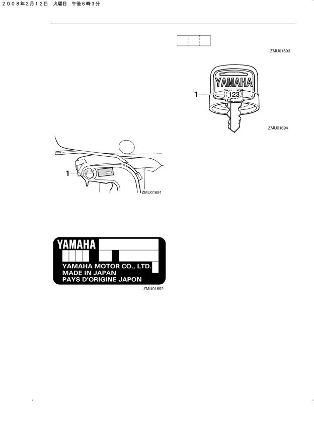
General information
EMU25171
Identification numbers record
EMU25183
Outboard motor serial number
The outboard motor serial number is stamped on the label attached to the port side of the clamp bracket.
Record your outboard motor serial number in the spaces provided to assist you in ordering spare parts from your Yamaha dealer or for reference in case your outboard motor is stolen.
1. Outboard motor serial number location
EMU25190
Key number
If a main key switch is equipped with the motor, the key identification number is stamped on your key as shown in the illustration. Record this number in the space provided for reference in case you need a new key.
1. Key number
EMU37290
EC Declaration of Conformity
(DoC)
This outboard motor conforms to certain portions of the European Parliament directive relating to machinery.
Each conformed outboard motor accompanied with EC DoC.EC DoC contains the following information;
●Name of Engine Manufacture
●Model name
●Product code of model (Approved model code)
●Code of conformed directives
EMU25203
CE Marking
Outboard motors affixed with this “CE”marking conform with the directives of; 98/37/EC, 94/25/EC — 2003/44/EC and 2004/108/EC.
4
![]()
General information
1
ZMU06200
1. CE marking location
ZMU06040
5
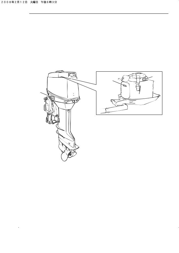
General information
EMU33520
Read manuals and labels
Before operating or working on this motor:
●Read this manual.
●Read any manuals supplied with the boat.
●Read all labels on the outboard motor and the boat.
If you need any additional information, contact your Yamaha dealer.
EMU33831
Warning labels
If these labels are damaged or missing, contact your Yamaha dealer for replacements.
6
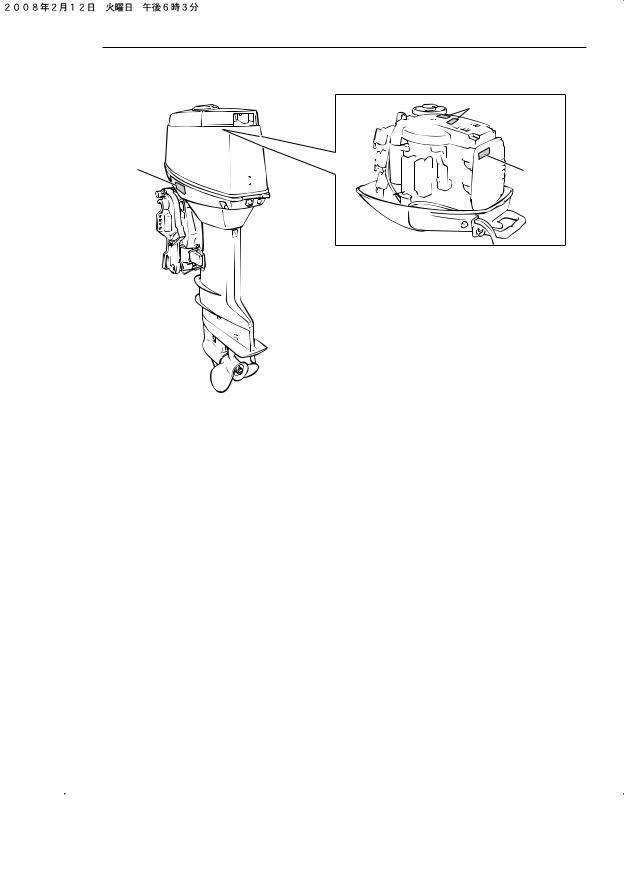
General information
|
30DEO, 30DETO |
|
|
1 |
|
|
3 |
2 |
|
ZMU06202 |
7

EMU33912
Contents of labels
The above warning labels mean as follows.
1
EWM01691
WARNING
Emergency starting does not have start- in-gear protection. Ensure shift control is in neutral before starting engine.
2
EWM01681
WARNING
●Keep hands, hair, and clothing away from rotating parts while the engine is running.
●Do not touch or remove electrical parts when starting or during operation.
ZMU05706
3
EWM01671
WARNING
●Read Owner’s Manuals and labels.
●Wear an approved personal flotation device (PFD).
●Attach engine shut-off cord (lanyard) to your PFD, arm, or leg so the engine stops if you accidentally leave the helm, which could prevent a runaway boat.
8
General information
EMU33843
Symbols
The following symbols mean as follows.
Notice/Warning
ZMU05696
Read Owner’s Manual
ZMU05664
Hazard caused by continuous rotation
ZMU05665
Electrical hazard
ZMU05666
Remote control lever/gear shift lever operating direction, dual direction
ZMU05667
Engine start/ Engine cranking
ZMU05668
9

Specifications and requirements
EMU31480
Specifications
TIP:
“(AL)” stated in the specification data below represents the numerical value for the aluminum propeller installed.
Likewise, “(SUS)” represents the value for stainless steel propeller installed and “(PL)” for plastic propeller installed.
EMU2821C
Dimension:
Overall length:
30DEO 662 mm (26.1 in) 30DETO 662 mm (26.1 in) 30DMHO 993 mm (39.1 in)
Overall width:
30DEO 307 mm (12.1 in) 30DETO 307 mm (12.1 in) 30DMHO 360 mm (14.2 in)
Overall height S:
30DEO 1140 mm (44.9 in) 30DMHO 1158 mm (45.6 in)
Overall height L:
30DEO 1261 mm (49.6 in) 30DETO 1261 mm (49.6 in) 30DMHO 1279 mm (50.4 in)
Transom height S:
30DEO 424 mm (16.7 in) 30DMHO 424 mm (16.7 in)
Transom height L: 545 mm (21.5 in)
Weight (AL) S:
30DEO 60.0 kg (132 lb) 30DMHO 60.0 kg (132 lb)
Weight (AL) L:
30DEO 62.0 kg (137 lb) 30DETO 66.0 kg (146 lb) 30DMHO 62.0 kg (137 lb)
Performance:
Full throttle operating range:
4500–5500 r/min Maximum output:
22.1 kW@5000 r/min
(30 HP@5000 r/min) Idling speed (in neutral):
30DEO 750 ±50 r/min 30DETO 1050 ±50 r/min 30DMHO 750 ±50 r/min
Engine:
Type: 2-stroke L
Displacement: 496.0 cm3 Bore × stroke:
59.5 × 59.5 mm (2.34 × 2.34 in) Ignition system:
CDI
Spark plug with resistor (NGK): BR7HS-10
Spark plug gap:
0.9–1.0 mm (0.035–0.039 in) Control system:
30DEO Remote control 30DETO Remote control 30DMHO Tiller
Starting system: 30DEO Electric 30DETO Electric 30DMHO Manual
Starting carburetion system: Choke valve
Min. cold cranking amps (CCA/EN): 30DEO 347.0 A
30DETO 347.0 A
Min. rated capacity (20HR/IEC): 30DEO 40.0 Ah
30DETO 40.0 Ah Alternator output:
30DMHO 80 W Maximum generator output:
30DEO 6.0 A
10

Specifications and requirements
30DETO 6.0 A
Drive unit:
Gear positions: Forward-neutral-reverse
Gear ratio:
1.85 (24/13) Trim and tilt system:
30DEO Manual tilt 30DETO Power trim and tilt 30DMHO Manual tilt
Propeller mark: F
Fuel and oil:
Recommended fuel:
Regular unleaded gasoline Min. research octane:
90
Fuel tank capacity:
25 L (6.60 US gal, 5.50 Imp.gal) Recommended engine oil:
YAMALUBE 2-stroke outboard motor oil
Lubrication:
Oil injection
Engine oil tank capacity:
0.9 L (0.95 US qt, 0.79 Imp.qt) Recommended gear oil:
Hypoid gear oil SAE#90 Gear oil quantity:
0.200 L (0.211 US qt, 0.176 Imp.qt)
Tightening torque for engine:
Spark plug:
25.0 Nm (2.55 kgf-m, 18.4 ft-lb) Propeller nut:
35.0 Nm (3.57 kgf-m, 25.8 ft-lb)
Noise and vibration level:
Operator sound pressure level (ICOMIA 39/94 and 40/94):
91.7 dB(A)
Sound power level (ICOMIA 39/94 and 40/94):
98.7 dB(A)
Vibration on tiller handle (ICOMIA 38/94): Vibration on tiller handle is under 2.5 m/s2
EMU33553
Installation requirements
EMU33563
Boat horsepower rating
EWM01560
 WARNING
Overpowering a boat can cause severe instability.
Before installing the outboard motor(s), confirm that the total horsepower of your motor(s) does not exceed the boats maximum horsepower rating. See the boat’s capacity plate or contact the manufacturer.
EMU33571
Mounting motor
EWM01570
 WARNING
●Improper mounting of the outboard motor could result in hazardous conditions such as poor handling, loss of control, or fire hazards.
●Because the motor is very heavy, special equipment and training is required to mount it safely.
Your dealer or other person experienced in proper rigging should mount the motor using correct equipment and complete rigging instructions. For further information, see page 27.
EMU33581
Remote control requirements
EWM01580
 WARNING
●If the engine starts in gear, the boat can move suddenly and unexpectedly, possibly causing a collision or throwing
11
Specifications and requirements
passengers overboard.
●If the engine ever starts in gear, the start-in-gear protection device is not working correctly and you should discontinue using the outboard. Contact your Yamaha dealer.
The remote control unit must be equipped with a start-in-gear protection device(s). This device prevents the engine from starting unless it is in neutral.
EMU25694
Battery requirements
EMU25721
Battery specifications
Minimum cold cranking amps (CCA/EN): 30DEO 347.0 A
30DETO 347.0 A
Minimum rated capacity (20HR/IEC): 30DEO 40.0 Ah
30DETO 40.0 Ah
The engine cannot be started if battery voltage is too low.
EMU36290
Mounting battery
Mount the battery holder securely in a dry, well-ventilated, vibration-free location in the boat. WARNING! Do not put flammable items, or loose heavy or metal objects in the same compartment as the battery. Fire, explosion or sparks could result.
[EWM01820]
EMU36300
Multiple batteries
To connect multiple batteries, such as for multiple engine configurations or for an accessory battery, consult your Yamaha dealer about battery selection and correct wiring.
EMU25730
Without a rectifier or Rectifier Regulator
ECM01090
NOTICE
A battery cannot be connected to models that do not have a rectifier or Rectifier Regulator.
If you wish to use a battery with the models without a rectifier or Rectifier Regulator, install an optional Rectifier Regulator.
Using a maintenance-free battery with the above models can shorten the life of the battery significantly.
Install an optional Rectifier Regulator or use accessories rated to withstand 18 volts or higher with the above models. Consult your Yamaha dealer for details on installing an optional Rectifier Regulator.
EMU34191
Propeller selection
Next to selecting an outboard, choosing the right propeller is one of the most important purchasing decisions a boater can make. The type, size, and design of your propeller have a direct impact on acceleration, top speed, fuel economy, and even engine life. Yamaha designs and manufactures propellers for every Yamaha outboard motor and every application.
Your outboard motor came with a Yamaha propeller chosen to perform well over a range of applications, but there may be uses where a different propeller would be more appropriate.
Your Yamaha dealer can help you select the right propeller for your boating needs. Select a propeller that will allow the engine to reach the middle or upper half of the operating range at full throttle with the maximum boatload. Generally, chose a larger pitch propel-
12
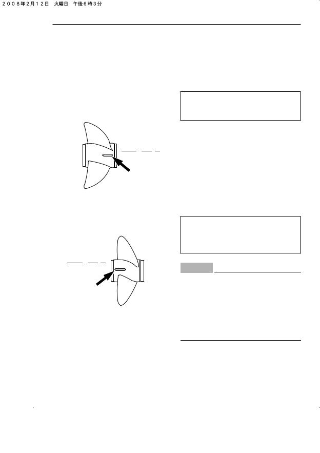
Specifications and requirements
ler for a smaller operating load and a smaller pitch propeller for a heavier load. If you carry loads that vary widely, chose the propeller that lets the engine run in the proper range for your maximum load but remember that you may need to reduce your throttle setting to stay within the recommended engine speed range when carrying lighter loads.
For instructions on propeller removal and installation, see page 65.

 x
x
 —
—
 1 2 3
1 2 3
ZMU04605
1.Propeller diameter in inches
2.Propeller pitch in inches
3.Type of propeller (propeller mark)

 x
x —
— 1 2 3
1 2 3
ZMU04606
1.Propeller diameter in inches
2.Propeller pitch in inches
3.Type of propeller (propeller mark)
EMU25770
Start-in-gear protection
proved remote control units are equipped with start-in-gear protection device(s). This feature permits the engine to be started only when it is in neutral. Always select neutral before starting the engine.
EMU25651
Engine oil requirements
Recommended engine oil: YAMALUBE 2-stroke outboard motor oil
If the recommended engine oil is not available, another 2-stroke engine oil with an NMMA-certified TC-W3 rating may be used.
EMU36360
Fuel requirements
EMU36801
Gasoline
Use a good quality gasoline that meets the minimum octane rating. If knocking or pinging occurs, use a different brand of gasoline or premium unleaded fuel.
Recommended gasoline:
Regular unleaded gasoline with a minimum octane rating of 90 (Research Octane Number).
ECM01980
NOTICE
●Do not use leaded gasoline. Leaded gasoline can seriously damage the engine.
●Avoid getting water and contaminants in the fuel tank. Contaminated fuel can cause poor performance or engine damage. Use only fresh gasoline that has been stored in clean containers.
EMU36880
Muddy or acidic water
Yamaha outboard motors or Yamaha-ap- Yamaha strongly recommends that you have
13
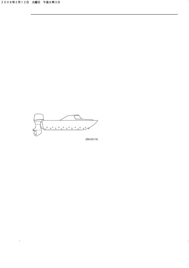
Specifications and requirements
your dealer install the optional chromiumplated water pump kit if you use the outboard motor in muddy or acidic water conditions. However, depending on the model it might not be required.
EMU36330
Anti-fouling paint
A clean hull improves boat performance. The boat bottom should be kept as clean of marine growth as possible. If necessary, the boat bottom can be coated with an anti-foul- ing paint approved for your area to inhibit marine growth.
Do not use anti-fouling paint which includes copper or graphite. These paints can cause more rapid engine corrosion.
EMU36340
Motor disposal requirements
Never illegally discard (dump) the motor Yamaha recommends consulting the dealer about discarding the motor.
EMU36351
Emergency equipment
Keep the following items onboard in case there is trouble with the motor.
●A tool kit with assorted screwdrivers, pliers, wrenches (including metric sizes), and electrical tape.
●Waterproof flashlight with extra batteries.
●An extra engine shut-off cord (lanyard) with clip.
●Spare parts, such as an extra set of spark plugs.
Consult your Yamaha dealer for details.
14
![]()
Components
EMU2579H
Components diagram
TIP:
* May not be exactly as shown; also may not be included as standard equipment on all mod-
|
els. |
||||
|
30DEO, 30DMHO, 30DETO |
||||
|
1 |
9 |
|||
|
10 |
||||
|
22 |
11 |
|||
|
2 |
12 |
|||
|
18 |
||||
|
14 |
13 |
|||
|
17 |
15 |
|||
|
3 |
16 |
|||
|
8 |
||||
|
19 |
||||
|
20 |
21 |
|||
|
7 |
4 |
|||
|
5 |
||||
|
6 |
||||
|
ZMU03758 |
1.Oil tank filler cap
2.Top cowling
3.Top cowling lock lever(s)
4.Anti-cavitation plate
5.Trim tab (anode)
6.Propeller
7.Cooling water inlet
8.Tilt rod*
9.Manual starter handle*
10.Engine stop button/Engine shut-off switch*
11.Alert indicator*
12.Gear shift lever*
13.Throttle grip*
14.Tilt lock lever*
15.Transom clamp handle*
16.Shallow water lever*
17.Rope attachment
18.Choke knob
19.Tilt support knob*
20.Remote control box (side mount type)*
21.Fuel tank
22.Clip*
EMU25802
Fuel tank
If your model was equipped with a portable fuel tank, its function is as follows.
EWM00020
 WARNING
The fuel tank supplied with this engine is
15

Components
its dedicated fuel reservoir and must not be used as a fuel storage container. Commercial users should conform to relevant licensing or approval authority regulations.
1.Fuel joint
2.Fuel gauge
3.Fuel tank cap
4.Air vent screw
EMU25830
Fuel joint
This joint is used to connect the fuel line.
EMU25841
Fuel gauge
This gauge is located on either the fuel tank cap or on the fuel joint base. It shows the approximate amount of fuel remaining in the tank.
EMU25850
Fuel tank cap
This cap seals the fuel tank. When removed, the tank can be filled with fuel. To remove the cap, turn it counterclockwise.
EMU25860
Air vent screw
This screw is on the fuel tank cap. To loosen the screw, turn it counterclockwise.
EMU26181
Remote control box
The remote control lever actuates both the shifter and the throttle. The electrical switch-
es are mounted on the remote control box.
1.Power trim and tilt switch
2.Remote control lever
3.Neutral interlock trigger
4.Neutral throttle lever
5.Main switch / choke switch
6.Engine shut-off switch
7.Throttle friction adjuster
EMU26190
Remote control lever
Moving the lever forward from the neutral position engages forward gear. Pulling the lever back from neutral engages reverse. The engine will continue to run at idle until the lever is moved about 35° (a detent can be felt). Moving the lever farther opens the throttle, and the engine will begin to accelerate.
1.Neutral “ ”
”
2.Forward “ ”
”
3.Reverse “ ”
”
16
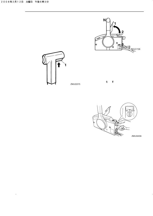
Components
4.Shift
5.Fully closed
6.Throttle
7.Fully open
EMU26201
Neutral interlock trigger
To shift out of neutral, first pull the neutral interlock trigger up.
1. Neutral interlock trigger
EMU26211
Neutral throttle lever
To open the throttle without shifting into either forward or reverse, put the remote control lever in the neutral position and lift the neutral throttle lever.
TIP:
The neutral throttle lever will operate only when the remote control lever is in neutral. The remote control lever will operate only when the neutral throttle lever is in the closed position.
1.Fully open
2.Fully closed
EMU26221
Choke switch
To activate the choke system, press in the main switch while the key is turned to the “ ” (on) or “
 ” (start) position. The choke system will then supply the rich fuel mixture required to start the engine. When the key is released, the choke will switch off automatically.
EMU25911
Tiller handle
To change direction, move the tiller handle to the left or right as necessary.
17
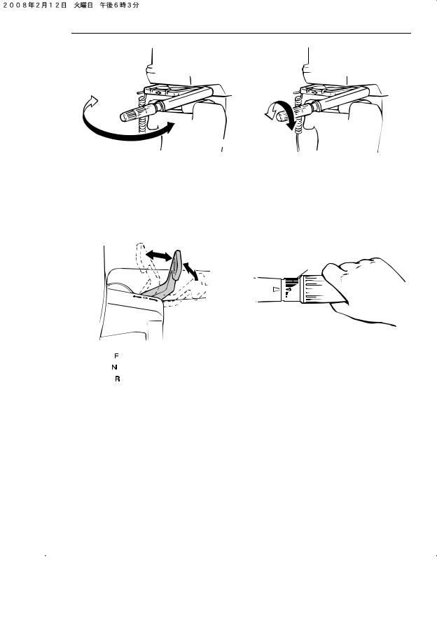
EMU25922
Gear shift lever
Pulling the gear shift lever towards you puts the engine in forward gear so that the boat moves ahead. Pushing the lever away from you puts the engine in reverse gear so that the boat moves astern.
EMU25961
Throttle indicator
The fuel consumption curve on the throttle indicator shows the relative amount of fuel consumed for each throttle position. Choose the setting that offers the best performance and fuel economy for the desired operation.
1
 F
F  1
1
1.Forward “ ”
2.Neutral “ ”
3.Reverse “ ”
EMU25941
Throttle grip
The throttle grip is on the tiller handle. Turn the grip counterclockwise to increase speed and clockwise to decrease speed.
1. Throttle indicator
EMU25973
Throttle friction adjuster
A friction device provides adjustable resistance to movement of the throttle grip or the remote control lever, and can be set according to operator preference.
To increase resistance, turn the adjuster clockwise. WARNING! Do not overtighten the friction adjuster. If there is too much resistance, it could be difficult to move the remote control lever or throttle grip, which could result in an accident. [EWM00032]
18
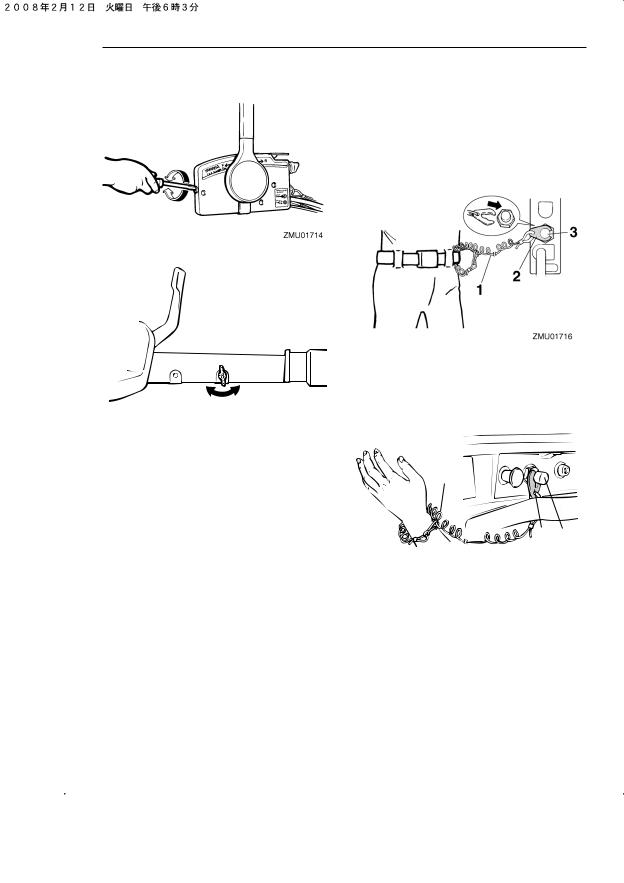
Components
To decrease resistance, turn the adjuster counterclockwise.
tangled, preventing it from functioning. Avoid accidentally pulling the cord during normal operation. Loss of engine power means the loss of most steering control. Also, without engine power, the boat could slow rapidly. This could cause people and objects in the boat to be thrown forward. [EWM00122]
When constant speed is desired, tighten the adjuster to maintain the desired throttle setting.
EMU25993
Engine shut-off cord (lanyard) and clip
The clip must be attached to the engine shutoff switch for the engine to run. The cord should be attached to a secure place on the operator’s clothing, or arm or leg. Should the operator fall overboard or leave the helm, the cord will pull out the clip, stopping ignition to the engine. This will prevent the boat from running away under power. WARNING! Attach the engine shut-off cord to a secure place on your clothing, or your arm or leg while operating. Do not attach the cord to clothing that could tear loose. Do not route the cord where it could become en-
1.Cord
2.Clip
3.Engine shut-off switch
1.Clip
2.Cord
3.Engine shut-off switch
EMU26001
Engine stop button
To open the ignition circuit and stop the engine, push this button.
19
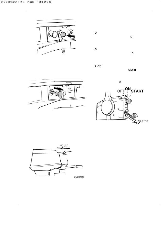
Components
ZMU03760
EMU26011
Choke knob for pull type
To supply the engine with the rich fuel mixture required to start, pull out this knob.
Manual starter handle
EMU26090
Main switch
The main switch controls the ignition system; its operation is described below.
● “  ” (off)
With the main switch in the “  ” (off) position, the electrical circuits are off, and the key can be removed.
● “  ” (on)
With the main switch in the “  ” (on) position, the electrical circuits are on, and the key cannot be removed.
|
● “ |
” (start) |
|
|
With the main switch in the “ |
” (start) po- |
sition, the starter motor turns to start the engine. When the key is released, it returns automatically to the “  ” (on) position.
To start the engine, first gently pull the han-
|
dle out until resistance is felt. From that posi- |
EMU26122 |
|
|
Steering friction adjuster |
||
|
tion, then pull the handle straight out quickly |
||
|
A friction device provides adjustable resis- |
||
|
to crank the engine. |
||
|
tance to the steering mechanism, and can be |
||
|
set according to operator preference. An ad- |
||
|
justing screw or bolt is located on the swivel |
||
|
bracket. |
20
Условные обозначения моделей лодочных моторов Honda
Все двигатели Honda — четырехтактные
Условные обозначения:
Буквы в обозначении мотора, например: BF 10 D2 S H S E
- BF – обозначение всех лодочных моторов производства Honda;
- 10 – мощность мотора в л.с.;
- D2 – семейство ( D ) и модельный год (2 = 2002г.);
- S, X, L – высота транца (короткий, длинный, сверхдлинный соответственно);
- H, R – тип управления (дистанционное управление или румпельная рукоятка);
Модели с дистанционным управлением оборудованы электростартером и выходом для зарядки аккумулятора 12В–6А. Все остальные типы оборудованы выходом для зарядки аккумулятора 12В-12А.
Эта позиция может отсутствовать:
- S – электрический стартер, система подзарядки аккумулятора 12В-12А (без электростартера 12В-6А);
- G – газовый подъём мотора;
- E – регион, для которого предназначен мотор ( E = Европа).
Расшифровка буквенных обозначений в лодочных моторах HONDA
BF — обозначение всех 4-х тактных лодочных моторов производства Honda
20 — мощность мотора в л.с.
A2 — семейство (A) и модельный год (2=2002г)
S — высота транца короткий 381 мм.(BF-20 D3 SRTE)
L — высота транца, длинный 508 мм.
X — высота транца, сверхдлинный, 635 мм.
E — регион, для которого предназначен мотор (E-европа);
B — система подзарядки аккумулятора (может не указываться)
H — управление с румпеля
R — дистанционное управление
S — электростартер (если S в последних 2-х буквах BF20D3 LHSU)
D — ручной запуск
G — подъем газовым цилиндром
T — электрогидроподъем