Руководство на английском языке по техническому обслуживанию и ремонту грузового автомобиля Iveco Stralis AT/AD.
- Автор: —
- Издательство: Iveco
- Год издания: 2003
- Страниц: 1507
- Формат: PDF
- Размер: 58,0 Mb

Руководство по эксплуатации и техническому обслуживанию + каталог запчастей грузовых автомобилей Iveco Stralis.
- Автор: —
- Издательство: Диез
- Год издания: —
- Страниц: 400
- Формат: —
- Размер: —

Руководство по ремонту грузовых автомобилей Iveco Stralis с двигателями Cursor 8, 10, 13.
- Автор: —
- Издательство: Диез
- Год издания: —
- Страниц: 544
- Формат: —
- Размер: —

Руководство по техническому обслуживанию и ремонту грузовых автомобилей Iveco Stralis стандартов евро 4 и евро 5 с 2007 года выпуска.
- Автор: —
- Издательство: Диез
- Год издания: —
- Страниц: 352
- Формат: —
- Размер: —

Руководство по эксплуатации и ремонту грузовых автомобилей Iveco Stralis стандартов евро 4 и евро 5 с 2007 года выпуска.
- Автор: —
- Издательство: Диез
- Год издания: —
- Страниц: 400
- Формат: —
- Размер: —

Руководство по ремонту грузовых автомобилей Iveco Stralis.
- Автор: —
- Издательство: Терция
- Год издания: —
- Страниц: 292
- Формат: —
- Размер: —

Руководство по техническому обслуживанию и ремонту грузового автомобиля Iveco Stralis.
- Автор: —
- Издательство: Iveco
- Год издания: 2001
- Страниц: 1748
- Формат: PDF
- Размер: 43,6 Mb

Руководство на итальянском языке по техническому обслуживанию и ремонту грузового автомобиля Iveco Stralis AT/AD.
- Автор: —
- Издательство: Iveco
- Год издания: 2004
- Страниц: 2232
- Формат: PDF
- Размер: 70,0 Mb

Руководство по эксплуатации, техническому обслуживанию и ремонту грузового автомобиля Iveco Stralis с 2002 года выпуска.
- Автор: —
- Издательство: Арго-Авто
- Год издания: —
- Страниц: 768
- Формат: —
- Размер: —

Руководство по эксплуатации и техническому обслуживанию грузового автомобиля Iveco Stralis.
- Автор: —
- Издательство: Iveco
- Год издания: 2001
- Страниц: 346
- Формат: PDF
- Размер: 3,2 Mb

libcats.org
Главная →

Iveco Stralis
Iveco Stralis КНИГИ,ТЕХНИКА Название: Iveco Stralis Издательство: Satiz msx Год: 2002 Страниц: 1748 Формат: pdfРазмер: 72,6 Mb Качество: Нормальное (ч/б) Язык: РусскийIveco Stralis. Руководство по ремонту и техническому обслуживанию.Описание: Техническая документация по ремонту автомобилей Iveco Stralis с двигателями Курсор 10 (в т.ч электрические схемы и регулировочные параметры).. 0
Скачать книгу бесплатно (pdf, 72.61 Mb)
Читать «Iveco Stralis»
Популярные книги за неделю:
#1
![]()
Ф.И.Бурдейный, Н.В.Казанский. Карманный справочник радиолюбителя-коротковолновика (1959, DjVu)
440 Kb
#2
![]()
Я.Войцеховский. Радиоэлектронные игрушки (1977, djvu)
13.76 Mb
#3
![]()
Подготовка саперов, подразделений специального назначения по разминированию
Категория: Научно-популярная литература (разное)
1.49 Mb
#4

128 советов начинающему программисту
Очков В.Ф., Пухначев Ю.В.
Категория: computers, computers, prog
8.91 Mb
#5

Английский язык в картинках
I.A. Richards; Christine M. Gibson
Категория: Иностранные языки
5.77 Mb
#6

Красота в изгнании. Королевы подиума
Александр Васильев
Категория: Исторические
21.01 Mb
#7

Ограждение участка. Ограды. Заборы. Калитки. Ворота
В.И.Рыженко
Категория: Строительство
1.23 Mb
#8

Эти загадочные зеркала
В. Правдивцев
Категория: Религия. Эзотерика
88.19 Mb
#9

Самоделки школьника
Тарасов Б.В.
Категория: science, science, technical, hobby, oddjob
41.91 Mb
#10
![]()
Наука и жизнь.Маленькие хитрости
Категория: E_Engineering, EM_Mechanics of elastic materials
3.50 Mb
Только что пользователи скачали эти книги:
#1
![]()
Жизнь и необыкновенные приключения капитан-лейтенанта Головнина, путешественника и мореходца
Категория: Морские приключения, Исторические приключения, Путешествия и география
6.17 Mb
#2

Надежность тягового подвижного состава
В.Г.Галкин, В.П.Парамзин, В.А.Четвергов
Категория: civil, civil, transport
1.84 Mb
#3
![]()
Философия науки — традиции и новации. Учебное пособие для вузов
Лешкевич Т.Г.
Категория: Философия логика этика
1.47 Mb
#4

Практика ремонта видеомагнитофонов
Родин А.В (ред)
4.94 Mb
#5
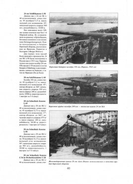
Артиллерия Вермахта
Категория: Вооружение
30.16 Mb
#6

Туган-Барановский М.И. Периодические промышленные кризисы
Туган-Барановский М.И.
Категория: science, , science, human
4.45 Mb
#7

Поспеловский Д. В. Русская православная церковь в XX веке
31.76 Mb
#8

Сто схем с индикаторами
Быстров Ю. А. и др.
Категория: АППАРАТУРА
1.98 Mb
#9

Целебное питание
Шаталова Г.С.
Категория: КНИГИ, ЗДОРОВЬЕ
12.98 Mb
#10
![]()
Домашний тренинг — максимум свободы
Домогацкий С.
Категория: спорт
21.60 Mb
Руководство по эксплуатации, техобслуживанию и ремонту Iveco Stralis
 3339 просмотров")
Дизельные двигатели: F2B, F3A
Выпуск: с 2002 года
Язык: Английский
Формат: PDF
Размер: 89,5 Мб
Скачать документацию Iveco Stralis
для распаковки архива используйте пароль — avtoproblem-net.ru
——————————
Язык: Русский
Формат: PDF
Размер: 61,3 Мб
Скачать документацию Iveco Stralis
для распаковки архива используйте пароль — avtoproblem-net.ru
- Главная
- Iveco
- Stralis
Автомобили Iveco Stralis относятся к категории грузовой техники, которая используется в основном для транспортировки различных видов грузов. Марка Iveco Stralis выпускается уже почти 20 лет, начиная с 2002 года. Модельный ряд марки достаточно широк и включает различные модификации автомобиля.
В разделе представлено большое количество информации, необходимой для эксплуатации автомобилей данной марки. Здесь можно заказать и скачать книги по ремонту, руководства по эксплуатации, инструкции в удобном формате PDF. Пособия станут полезными не только для частного использования, но и для применения профессиональными мастерами.
Обновление цен:
23.04.2023
Диапазон цен:
1292 — 1922 руб.
Руководство по ремонту Iveco Stralis с 2007 г., ЕВРО-4/5, Том 1
Книга-руководство по ремонту, эксплуатации, техническим обслуживаниям, индетификациям, двигателям, сцеплению, колёсам, по плановым диагностикам и внешнему строению марки грузового автомобиля Iveco Stralis Евро 4, Евро 5 с 2007 года выпуска.
- от 1730 руб.
- 2007 — 2020 гг.
- бензин
- скачать
Книга по эксплуатации и ремонту Iveco Stralis, дизель
Книга по ремонту Iveco Stralis рассчитана на тягачи с 2002 г. в., которые оснащены турбированными и атмосферными дизельными моторами Cursor 13/10/8 объемом 12.8, 10.3 и 7.8 л. соответственно. Встречаются иные обозначения двигателей (указаны по порядку): F3B, F2A, F2B.
- от 1292 руб.
- 2002 — 2020 гг.
- дизель
- скачать

-
Contents
-
Table of Contents
-
Bookmarks
Related Manuals for Iveco Stralis MY 2016
Summary of Contents for Iveco Stralis MY 2016
-
Page 1
I S S U E 0 3 — 2 0 1 9… -
Page 2
IVECO S.p.A Homologation, Technical Application & Regulation Lungo Stura Lazio, 49 10156 Torino (TO) — Italy www.iveco.com Printed 692.68.697 – 5 Ed. 03/2019 Images and text: IVECO S.p.A. 2019 All rights reserved. -
Page 3
UPDATE DATA Section Chapter Description Revision date – Printed 692.68.697 – 5 Ed. — Base 03/2019… -
Page 4
Data and information contained in this publication may be outdated as a result of changes adopted by IVECO, at any time, for tech- nical or commercial reasons or due to the need to adapt the vehicle to new legal requirements. -
Page 5
INDEX OF SECTIONS GENERAL INFORMATION CHASSIS INTERVENTIONS APPLICATIONS OF SUPERSTRUCTURES POWER TAKE-OFFS ELECTRONIC SUB-SYSTEMS ADBLUE AND SCRT SYSTEM STRALIS NP — CURSOR CNG-LNG — Printed 692.68.697 – 5 Ed. — Base 03/2019… -
Page 6
— Printed 692.68.697 – 5 Ed. — Base 03/2019… -
Page 7
SECTION 1 GENERAL INFORMATION — Printed 692.68.697 – 5 Ed. — Base 03/2019… -
Page 8
— Printed 692.68.697 – 5 Ed. — Base 03/2019… -
Page 9: Table Of Contents
ELECTRONICALLY ….. . . 1.3 IVECO AUTHORISATION ….
-
Page 10
NEW STRALIS MY2016 ‒ GUIDELINES FOR BODYBUILDERS GENERAL INFORMATION – Printed 692.68.697 – 5 Ed. — Base 03/2019… -
Page 11: Scope Of The Guidelines
It should be noted that the collaboration with IVECO is based on the assumption that the Bodybuilder uses the maximum of their technical and organisational skills and that operations are technically and perfectly complete. As outlined below, the topic is extens- ive and we can only provide the rules and minimum precautions that can allow development of the technical initiative.
-
Page 12: Authorisation Request
● the implementation; ● the compliance of the design and implementation to any specific indications provided by IVECO and the laws in force in the countries where the vehicle is destined; ● effects on functionality, safety, reliability and, in general, good behaviour of the vehicle;…
-
Page 13: Warranties
(e.g. approval documents/test reports). Before signing the Technical Agreement IVECO reserves the right to visit the Bodybuilder, in order to verify qualifications to carry out the fittings and/or processing for which the above collaboration is requested.
-
Page 14: Quality System Management
● training and qualification of staff. The availability of ISO 9001 certification, even though not required, is considered very important by IVECO. 1.10 ACCIDENT PREVENTION Do not allow unauthorised personnel to intervene or operate on the vehicle. It is forbidden to use the vehicle with safety devices that have been tampered with or are damaged.
-
Page 15: Vehicle Management On The Part Of Bodybuilder
12.1 V the battery should be replaced. Note The batteries must be maintained at regular intervals (refer to IVECO Std 20-1812 and/or IVECO Std 20-1804) until delivery of the vehicle to the Customer/Dealer to avoid problems of insufficient charging, short circuit or corrosion.
-
Page 16: Vehicle Names
NEW STRALIS MY2016 ‒ GUIDELINES FOR BODYBUILDERS GENERAL INFORMATION 1.13 VEHICLE NAMES 1.13 VEHICLE NAMES The commercial name of IVECO vehicles (for example STRALIS 480 E6) does not match the type approval name. A complete example is provided below. Type approval name STRALIS HI-WAY 440 S 48 T/P ●…
-
Page 17: Trademarks And Symbols
The dimensions and masses of vehicles allowed on the axles are shown in the drawings, the technical descriptions and, more gener- ally, on the documents on the official IVECO website. Defects refer to vehicles in their standard versions; the use of special equip- ment may lead to changes on the masses and their distribution on the axles.
-
Page 18
NEW STRALIS MY2016 ‒ GUIDELINES FOR BODYBUILDERS GENERAL INFORMATION 1.15 DIMENSIONS AND GROUND Figure 2 192336 Example to determine the placement of the centre of gravity of the payload plus superstructure (Vehicle with 2 axles; vehicles with 3 axles having equal loads on two rear axles) Front wheel axle or tandem centre line L1 = Distance of centre of gravity from the centre line of the… -
Page 19
NEW STRALIS MY2016 ‒ GUIDELINES FOR BODYBUILDERS GENERAL INFORMATION 1.15 DIMENSIONS AND GROUND Note For vehicles with three or more axes, with variable ratio of the distribution of the masses on the two rear axles depending on the load, the «virtual» value of the wheelbase and the centre line between the axles must be determined for the respective load condi- tion realized, using the instructions on the vehicle cab diagram. -
Page 20
● in considering (for liquids) the density; ● in prescribing the adoption of adequate precautions for driving. Any cases where evaluation is difficult should be submitted to IVECO for approval. – Printed 692.68.697 – 5 Ed. — Base 03/2019… -
Page 21: Respect Of The Permitted Masses
Respect of the permitted masses All the limits shown on IVECO documentation must be respected. It is particularly important to evaluate the maximum ground on the front axle in any load condition, in order to ensure the necessary steering features in all road surface conditions.
-
Page 22: Instructions For Proper Functioning Of The Vehicle Parts And Accessibility
NEW STRALIS MY2016 ‒ GUIDELINES FOR BODYBUILDERS GENERAL INFORMATION 1.16 INSTRUCTIONS FOR PROPER FUNCTIONING OF THE VEHICLE PARTS AND ACCESSIBILITY Variations on permitted masses Special exemptions from the maximum permissible masses may be granted for specific uses, for which, however, there are precise limits for use and reinforcements to be made to parts of the vehicle.
-
Page 23
These dimensions are shown on the diagrams for Bodybuilders available on the website www.ibb.iveco.com; ●… -
Page 24: Exhaust System Accessibility (Only Diesel Versions)
NEW STRALIS MY2016 ‒ GUIDELINES FOR BODYBUILDERS GENERAL INFORMATION 1.16 INSTRUCTIONS FOR PROPER FUNCTIONING OF THE VEHICLE PARTS AND ACCESSIBILITY Exhaust system accessibility (only diesel versions) Each outfitting must ensure access to the exhaust gas post-treatment assembly (muffler) and, in particular, to the cover of the ceramic particulate filter housing.
-
Page 25
NEW STRALIS MY2016 ‒ GUIDELINES FOR BODYBUILDERS GENERAL INFORMATION 1.17 GENERAL REGULATION FOR THE PREVENTION OF FIRE RISK 1.17 GENERAL REGULATION FOR THE PREVENTION OF FIRE RISK Particular attention must be paid to prevent the spillage of hydraulic fluids or inflammable liquids above components which may become hot or overheated. -
Page 26
NEW STRALIS MY2016 ‒ GUIDELINES FOR BODYBUILDERS GENERAL INFORMATION – Printed 692.68.697 – 5 Ed. — Base 03/2019… -
Page 27
SECTION 2 CHASSIS INTERVENTIONS — Printed 692.68.697 – 5 Ed. — Base 03/2019… -
Page 28
— Printed 692.68.697 – 5 Ed. — Base 03/2019… -
Page 29
NEW STRALIS MY2016 ‒ GUIDELINES FOR BODYBUILDERS CHASSIS INTERVENTIONS Contents Contents 2.7 ASSEMBLING AN ADDITIONAL AXLE ..General information ….2.1 GENERAL CHASSIS MODIFICATION Reinforcements on the chassis . -
Page 30
NEW STRALIS MY2016 ‒ GUIDELINES FOR BODYBUILDERS CHASSIS INTERVENTIONS Contents 2.17 PART RELOCATION AND ANCHORAGE OF ADDITIONAL UNITS AND EQUIPMENT ..Spare wheel holder ….Additional fuel tank (only diesel vehicles) . -
Page 31: General Chassis Modification Standards
NEW STRALIS MY2016 ‒ GUIDELINES FOR BODYBUILDERS CHASSIS INTERVENTIONS 2.1 GENERAL CHASSIS MODIFICATION STANDARDS CHASSIS INTERVENTIONS 2.1 GENERAL CHASSIS MODIFICATION STANDARDS Keep in mind that: ● weldings on the supporting structures of the chassis are absolutely forbidden (except as prescribed in Para- graph»Weldings»…
-
Page 32: Characteristics Of The Material Used In Chassis Modifications
If it is not possible to procure materials of the thickness indicated, materials having immediately higher standard thickness may be employed. Table 2.1 — Material to be used in chassis modifications Breaking strength Yield stress Name of steel Elongation [N/mm [N/mm IVECO Fe E490 Europe S500MC Germany QStE500TM IVECO Fe 510D Europe…
-
Page 33: Stresses On The Chassis
NEW STRALIS MY2016 ‒ GUIDELINES FOR BODYBUILDERS CHASSIS INTERVENTIONS 2.2 DRILLS ON THE CHASSIS Area of side member near wheelbase A x B x t Wheelbase Model [mm] [mm] (see Figure 6) STRALIS 440 T/*P (-LT), TX/P 289 x 80 x 6.7 STRALIS 440 T/P (-HR, -RR), TY/P, TY/PT, TZ/P-HM 289 x 80 x 7.7 Stresses on the chassis…
-
Page 34: Screws And Nuts
NEW STRALIS MY2016 ‒ GUIDELINES FOR BODYBUILDERS CHASSIS INTERVENTIONS 2.2 DRILLS ON THE CHASSIS Screws and nuts We generally recommend the use of the same type and class of screws and nuts as those employed for similar anchorages on the original vehicle (see Table 2.3). Table 2.3 — Screws resistance classes Breaking strength Yield stress…
-
Page 35
NEW STRALIS MY2016 ‒ GUIDELINES FOR BODYBUILDERS CHASSIS INTERVENTIONS 2.2 DRILLS ON THE CHASSIS ● if an electric circuit breaker (main switch) is present, wait for it to complete the cycle; ● disconnect the negative pole from the battery; ● disconnect the positive pole of the battery without connecting it to earth; do NOT short-circuit the negative pole; ●… -
Page 36: Sealing Holes By Welding
Holes of 20 mm diameter can be sealed off by using chamfered washers welded on both sides. 2.3 RUST AND PAINT PROTECTION Note All components mounted on the chassis must be painted in compliance with IVECO Standard 18-1600 Colour IC444 RAL 7021 — 70/80 gloss. Original vehicle parts The following tables show, respectively, the classes of coating and protection required for the original vehicle components, the protections required for the parts not painted or in aluminium and treatments required for the painted parts.
-
Page 37
NEW STRALIS MY2016 ‒ GUIDELINES FOR BODYBUILDERS CHASSIS INTERVENTIONS 2.3 RUST AND PAINT PROTECTION Table 2.5 — Unpainted aluminium parts — IVECO Standard 18 — 1600 (Table IV) Classes IVECO Type of protection standard B — B1 — B2 – –… -
Page 38: Added Or Modified Parts
NEW STRALIS MY2016 ‒ GUIDELINES FOR BODYBUILDERS CHASSIS INTERVENTIONS 2.3 RUST AND PAINT PROTECTION Classes Cycle phase description – Bi-component (30-40 μm) – RUST PREVENTER – – Single-component (30-40 μm) Single (130 °C) or bicomponent (30-40 μm) – – – – –…
-
Page 39: Precautions
NEW STRALIS MY2016 ‒ GUIDELINES FOR BODYBUILDERS CHASSIS INTERVENTIONS 2.3 RUST AND PAINT PROTECTION Table 2.8 — Unpainted or aluminium modified parts or add-ons Class Type of protection A — B – Stainless steel – Geomet – Zinc coating Free from hexavalent chromium Precautions a) On the vehicle Appropriate precautions must be taken to protect parts on which paint could be harmful to the conservation and operation…
-
Page 40: Wheelbase Modification
If the dimensions of the superstructure are suitable, it is best to use wheelbases in standard production because this allows the use of original drive shafts and pre-defined crossbar positions. Nevertheless, IVECO must issue its authorisation for wheelbases below the minimum or maximum approved standard sizes on the market.
-
Page 41: Effects On Braking
Generally speaking, shortening the wheelbase will have a negative effect on braking. Contact the IVECO Department — Homologation & Technical Application to find out at what conditions (brake cylinders, minimum tare, theoretically admissible loads, tyres, height of centre of gravity) transformation can be allowed.
-
Page 42: Checking Chassis Stress
— along the entire contour of the wheelbase — until achieving area strength modulus equal to IVECO values for the same wheelbase or for the next admissible greater length. In alternative, for cases allowed by local standards, larger counter-frame profiles can be adopted.
-
Page 43: Gearbox Modifications
NEW STRALIS MY2016 ‒ GUIDELINES FOR BODYBUILDERS CHASSIS INTERVENTIONS 2.5 REAR OVERHANG MODIFICATION Gearbox modifications See Chapter 2.8 ( ➠ Page 38) for checks of modifications allowed. 2.5 REAR OVERHANG MODIFICATION General information When modifying the rear overhang, the limits set by national standards must be respected. This is also the case for the maximum distances from the rear structural edge and distance from the ground, defined for the tow hook and under-run protection.
-
Page 44
NEW STRALIS MY2016 ‒ GUIDELINES FOR BODYBUILDERS CHASSIS INTERVENTIONS 2.5 REAR OVERHANG MODIFICATION Figure 7 91454 1. Added part 3. Reinforcing profile (alternative solution) 2. Reinforcing profile 4. Original rear cross member Figure 8 91455 1. Added part 3. Original rear cross member 2. -
Page 45: Installing The Tow Hook
NEW STRALIS MY2016 ‒ GUIDELINES FOR BODYBUILDERS CHASSIS INTERVENTIONS 2.6 INSTALLING THE TOW HOOK 2.6 INSTALLING THE TOW HOOK General information The application of a tow hook is possible without authorization: ● on vehicles with the specifically prescribed crossbar (opt. 6151) for inertia trailers; ●…
-
Page 46
NEW STRALIS MY2016 ‒ GUIDELINES FOR BODYBUILDERS CHASSIS INTERVENTIONS 2.6 INSTALLING THE TOW HOOK Figure 9 196787 1. 2. Free field for towing hooks Free field for coupling hooks according to standard DIN 74058 ESC-152 – Printed 692.68.697 – 5 Ed. — Base 03/2019… -
Page 47: Towing Hooks For Conventional Trailers
NEW STRALIS MY2016 ‒ GUIDELINES FOR BODYBUILDERS CHASSIS INTERVENTIONS 2.6 INSTALLING THE TOW HOOK Towing hooks for conventional trailers According to Directive 94/20/CE, both for the choice of the hook and for the application of any reinforcements to the rear cross- bar, it is important to take into account the action of the horizontal forces generated by the masses of the tractor and trailer, based on the following formula: D = 9.81 (T •…
-
Page 48
If you wish to use the tow with a vehicle not originally designed (and in compliance with the limits established by IVECO for each model), only original rear cross members which have already been hole punched can be mounted. Towable masses and the bear- able vertical loads can be defined based on the size of the hole. -
Page 49
NEW STRALIS MY2016 ‒ GUIDELINES FOR BODYBUILDERS CHASSIS INTERVENTIONS 2.6 INSTALLING THE TOW HOOK Towable mass (R) and static load (S) on the hook of the centre axle trailer [kg] Wheel- Over- Models R≤9500 R≤12000 R≤14000 R≤16000 R≤18000 R≤20000 R≤22000 R≤24000… -
Page 50
NEW STRALIS MY2016 ‒ GUIDELINES FOR BODYBUILDERS CHASSIS INTERVENTIONS 2.6 INSTALLING THE TOW HOOK Towable mass (R) and static load (S) on the hook of the centre axle trailer [kg] Wheel- Over- Models R≤9500 R≤12000 R≤14000 R≤16000 R≤18000 R≤20000 R≤22000 R≤24000… -
Page 51
NEW STRALIS MY2016 ‒ GUIDELINES FOR BODYBUILDERS CHASSIS INTERVENTIONS 2.6 INSTALLING THE TOW HOOK Towable mass (R) and static load (S) on the hook of the centre axle trailer [kg] Wheel- Over- Models R≤9500 R≤12000 R≤14000 R≤16000 R≤18000 R≤20000 R≤22000 R≤24000… -
Page 52
NEW STRALIS MY2016 ‒ GUIDELINES FOR BODYBUILDERS CHASSIS INTERVENTIONS 2.6 INSTALLING THE TOW HOOK Towable mass (R) and static load (S) on the hook of the centre axle trailer [kg] Wheel- Over- Models R≤9500 R≤12000 R≤14000 R≤16000 R≤18000 R≤20000 R≤22000 R≤24000… -
Page 53
NEW STRALIS MY2016 ‒ GUIDELINES FOR BODYBUILDERS CHASSIS INTERVENTIONS 2.6 INSTALLING THE TOW HOOK Towable mass (R) and static load (S) on the hook of the centre axle trailer [kg] Wheel- Over- Models R≤9500 R≤12000 R≤14000 R≤16000 R≤18000 R≤20000 R≤22000 R≤24000… -
Page 54
NEW STRALIS MY2016 ‒ GUIDELINES FOR BODYBUILDERS CHASSIS INTERVENTIONS 2.6 INSTALLING THE TOW HOOK Towable mass (R) and static load (S) on the hook of the centre axle trailer [kg] Wheel- Over- Models R≤9500 R≤12000 R≤14000 R≤16000 R≤18000 R≤20000 R≤22000 R≤24000… -
Page 55: Rear Crossbar In Lowered Position
Rear crossbar in lowered position When the tow hook must be lowered from its original position, IVECO may issue an authorisation to lower the original drawbar or install an additional drawbar, which is the same as the original, in a lowered positioned.
-
Page 56
NEW STRALIS MY2016 ‒ GUIDELINES FOR BODYBUILDERS CHASSIS INTERVENTIONS 2.6 INSTALLING THE TOW HOOK Figure 11 245555 1. Original rear cross member. 3. M14 threaded hole — 10.9 (1/10 kN) 2. Additional strap 4. Connecting corner The outer corners should have a thickness of not less than that of the side members of the vehicle, they should extend in length for a distance of at least 2.5 times the height of the side member itself (max 600 mm) and should use a material with the minimum requirements set out in Chapter 3.3 — Paragraph «Choosing the type of connection»… -
Page 57
NEW STRALIS MY2016 ‒ GUIDELINES FOR BODYBUILDERS CHASSIS INTERVENTIONS 2.6 INSTALLING THE TOW HOOK Figure 12 192344 1. Lowered rear cross member 4. Connecting plate 2. Connecting plate or angle 5. C-profile (same dimensions as chassis) 3. Coupling plate 6. Space for rear spring retainer The movements between the drawbar and the vehicle established by regulations in force must be ensured. -
Page 58
NEW STRALIS MY2016 ‒ GUIDELINES FOR BODYBUILDERS CHASSIS INTERVENTIONS 2.6 INSTALLING THE TOW HOOK Tow beam in a lowered and forward position (close coupling) for centre axle trailers Vehicles that, to tow centre axle trailers, must adopt a two beam in a lowered and forward position (close to the rear housings of the rear suspension or air springs), do not require special chassis reinforcement. -
Page 59
Chapter 1.15 ( ➠ Page 11). Increase of tow weight As regards tow vehicles, IVECO may evaluate — in certain cases and for particular applications — the possibility to authorise greater tow weights than those normally allowed. -
Page 60: Assembling An Additional Axle
On some models of the Stralis range, it may be possible to apply an additional axle and consequently increase gross vehicle mass. For its implementation, the mass limits and conditions imposed by IVECO must be respected, as well as all other conditions reques- ted by national laws and the necessity to ensure driving safety and proper vehicle function.
-
Page 61: Added Axle
NEW STRALIS MY2016 ‒ GUIDELINES FOR BODYBUILDERS CHASSIS INTERVENTIONS 2.7 ASSEMBLING AN ADDITIONAL AXLE In the case of a subframe reinforcement, the anchors provided on the chassis may be used (if in existence), otherwise they should be made according to the indications in Chapter 3.1 — Paragraph «Sizing of profiles» ( ➠ Page 5) and subsequent paragraphs. We recommend creating a cut-resistant joint in the area of the rear overhang and for about half of the wheelbase length (and always for lengths of at least 2 m from the front axle) (see Figure 15).
-
Page 62: Steering Axles
Exception is made for fittings or special uses for which, in order to increase suspension rigidity, the application of rubber elastic elements may be authorised. In special cases and only after IVECO approval, the addition of supplemental sheets on the parabolic springs may be allowed; this must be carried out by a specialised spring manufacturer.
-
Page 63: Stabiliser Bars
NEW STRALIS MY2016 ‒ GUIDELINES FOR BODYBUILDERS CHASSIS INTERVENTIONS 2.7 ASSEMBLING AN ADDITIONAL AXLE Stabiliser bars In the case of an additional axle with air suspension, it might be necessary, depending on the solution adopted, to provide a stabiliser bar, particularly when there is a superstructure with high centre of gravity. Similar stability measures should be adopted for mixed suspensions on added rear axles.
-
Page 64: Lifting Device
The maximum tilt values of the standard propeller shafts must be respected, also in the event of interventions on the suspension and on the engine rear axle. Contact the IVECO Technical Application for any difficulties; and send them a diagram with the length and tilt of the new transmis- sion for a constant-velocity check.
-
Page 65: Lengths Allowed
NEW STRALIS MY2016 ‒ GUIDELINES FOR BODYBUILDERS CHASSIS INTERVENTIONS 2.8 TRANSMISSION MODIFICATION Values that must be valid both when the vehicle is empty (tare only) and when the vehicle has a static load considering the max- imum allowed load on the rear axle. The scope of these instructions is to safeguard proper operation of the gearbox, limit sound level and avoid stress transmitted by the drive assembly.
-
Page 66
NEW STRALIS MY2016 ‒ GUIDELINES FOR BODYBUILDERS CHASSIS INTERVENTIONS 2.8 TRANSMISSION MODIFICATION Engine Model Engine code Power [HP — kW] F2CFE611B*J 360 — 265 2200 CURSOR 9 F2CFE611A*J 400 — 294 2200 F3GFE611F*J 420 — 309 1900 F3GFE611E*J 460 — 338 1900 CURSOR 11 F3GFE611D*J (with EGR) -
Page 67: Positioning The Sections
NEW STRALIS MY2016 ‒ GUIDELINES FOR BODYBUILDERS CHASSIS INTERVENTIONS 2.8 TRANSMISSION MODIFICATION Table 2.13 — Maximum possible lengths Maximum possible lengths LG to LZ [mm] External diameter x Joint dimensions 1800 1900 2000 2100 2200 2300 2400 2500 thickness [mm] Maximum propeller shaft speed [rpm] 2040 100 x 4.5 3400…
-
Page 68
The application of flexible supports must be done using support plates with a thickness of at least 5 mm (see Figure 22), connected to cross members with characteristics similar to those specified by IVECO. In modifying the wheelbase, it is best to plan for disassembly of intermediate shafts when shaft length is less than approximately 800… -
Page 69: Modifying The Engine Air Intake And Exhaust Systems
Furthermore, the wheelbase on these vehicles may not be reduced beyond the shortest value for the series (e.g. tipper truck). We recommend using original IVECO gearboxes; if this is not possible, the use of raw steel pipes with a yield load of at least 420…
-
Page 70: Intake
NEW STRALIS MY2016 ‒ GUIDELINES FOR BODYBUILDERS CHASSIS INTERVENTIONS 2.10 WORK ON THE ENGINE COOLING SYSTEM Exhaust Engine Model Engine code Intake vacuum [kPa] counter-pressure [kPa] F3HFE611G*J CURSOR 13 F3HFE611D*J F3HFE611F*J Intake The air intake must be mounted as to avoid intake of hot air from the engine compartment, or dust and water. The intake compartment must be sealed airtight and fitted with rubber gaskets that prevent hot air recirculation.
-
Page 71: Installing An Additional Heating System
We recommend using IVECO type heating systems whenever it is necessary to install an additional heating system. On vehicles where IVECO does not employ these heaters, installation must be done in compliance with the instructions issued by the equipment Manufacturer (installation of heaters, pipes, electric system, etc.) and in relation to the following indications.
-
Page 72: Installing An Air Conditioning System
● installation of the evaporator unit and of the bellow inside the cab (in cases where not provided directly from IVECO) must be planned as not to negatively impact control functions and access to equipment; b) cab roof-installed systems : ●…
-
Page 73: Work On The Cab
General information Note All interventions on the driver’s cab or on the roof must be authorised by IVECO in advance. The modifications must not hinder operation of the control devices located in the area of the modification (e.g. pedals, switches, pipes, etc.) nor alter the strength of load-bearing elements (frames, reinforcement profiles, etc.).
-
Page 74: Changing Tyre Size
Note Replacing the tyres with others of measure or load bearing capacity that differs from the specifications recorded at vehicle approval require IVECO certification, as well as a test to determine whether the braking system requires adjustment. The vehicle must successively be presented to the competent Body that will inspect the new tyres and the vehicle documents.
-
Page 75: Work On The Braking System
● on hydraulic lines. Operations must provide: ● materials and dimensions: Standard DIN 74324 (IVECO STD 18-0400) Maximum operating pressure 12.5 bar ● radii of curvature (referring to the centre line of the pipe): ■ Φ 6 to 35 mm…
-
Page 76
■ Φ 16 to 85 mm Preparation and assembly (IVECO STD 17-2403) Cut the pipe at right angles (15° maximum error), using a special tool in order to avoid imperfections that affect the sealing. Permanently mark the section of pipe (dimension L in Figure 23) to be inserted into the coupling to ensure secure sealing. -
Page 77
NEW STRALIS MY2016 ‒ GUIDELINES FOR BODYBUILDERS CHASSIS INTERVENTIONS 2.15 WORK ON THE BRAKING SYSTEM Vehicle pipe installation Before use, the new pipes must be thoroughly cleaned inside, for example by blowing air with a compressor. The pipes must be fixed to the frame with elements which envelop the pipe completely and which may be metal with rubber/plastic protection or be made of plastic material. -
Page 78: Abs Electronic Brake Control Devices
In vehicles with a pneumatic braking system, it is possible to withdraw a small amount of air from the auxiliary pneumatic circuit. To protect the auxiliary users (vehicle side), the connection is only possible with an additional overpressure valve (IVECO 8169974 EZ) without reflux and with an opening pressure of 6.7 — 7.0 bar.
-
Page 79: Electrical System: Current Interventions And Draws
NEW STRALIS MY2016 ‒ GUIDELINES FOR BODYBUILDERS CHASSIS INTERVENTIONS 2.16 ELECTRICAL SYSTEM: CURRENT INTERVENTIONS AND DRAWS 2.16 ELECTRICAL SYSTEM: CURRENT INTERVENTIONS AND DRAWS For information on work on the electrical system and the current draws, refer to indications provided in Section 5 — Chapter 5.6 ( ➠…
-
Page 80
NEW STRALIS MY2016 ‒ GUIDELINES FOR BODYBUILDERS CHASSIS INTERVENTIONS 2.17 PART RELOCATION AND ANCHORAGE OF ADDITIONAL UNITS AND EQUIPMENT Figure 26 196784 The chosen solution must be implemented in compliance with specific regulations. The piping additions must ensure prefect sealing, have technical features and internal dimensions not less than those provided for in the original system and be properly clamped. -
Page 81: Moving To The Opposite Side Member (Only Diesel Vehicles)
NEW STRALIS MY2016 ‒ GUIDELINES FOR BODYBUILDERS CHASSIS INTERVENTIONS 2.17 PART RELOCATION AND ANCHORAGE OF ADDITIONAL UNITS AND EQUIPMENT Moving to the opposite side member (only diesel vehicles) Figure 27 245556 The fuel tank can be moved to the left side member providing a minimum distance of 200 mm from the DPF/muffler housing is maintained.
-
Page 82: Transport Of Hazardous Materials (Adr)
The possibility of adopting a different brake type from the original (for example, with electro-magnetic actuation) requires compat- ibility with the characteristics of the vehicle and what has already been approved by IVECO. Please note that any unauthorised work on the original retarder will invalidate the vehicle warranty.
-
Page 83: Rear Under-Run Protection (Rup)
2.21 REAR MUD GUARDS AND WHEEL ARCHES On cab version vehicles without rear fenders, the Bodybuilder must implement solutions equal to those provided by IVECO. For the realisation of the fenders, the wheel arch boxes and the shaping of the superstructure, keep in mind that: ●…
-
Page 84: Rain Flap
NEW STRALIS MY2016 ‒ GUIDELINES FOR BODYBUILDERS CHASSIS INTERVENTIONS 2.22 RAIN FLAP In this figure, the dimensions refer to tyres 315/80 R 22.5; with the measurement 385/65 R 22.5 the dimensions in section A-A must be increased by 50 mm. Figure 31 116725 …
-
Page 85
Figure 32 192349 A For the IVECO profile C Test load 1 kN — Sagging allowed under the test load: ≤ B With the lower part of the superstructure over 1300 mm 30 mm on the rear part, including the last 250 mm of the device;… -
Page 86
NEW STRALIS MY2016 ‒ GUIDELINES FOR BODYBUILDERS CHASSIS INTERVENTIONS – Printed 692.68.697 – 5 Ed. — Base 03/2019… -
Page 87
SECTION 3 APPLICATIONS OF SUPERSTRUCTURES — Printed 692.68.697 – 5 Ed. — Base 03/2019… -
Page 88
— Printed 692.68.697 – 5 Ed. — Base 03/2019… -
Page 89
NEW STRALIS MY2016 ‒ GUIDELINES FOR BODYBUILDERS APPLICATIONS OF SUPERSTRUCTURES Contents Contents 3.9 INSTALLATION OF TAIL LIFTS … Procedure for calculating the bending moment 3.1 CONSTRUCTION OF THE SUBFRAME ..on the chassis with overhangs not provided as standard . -
Page 90
NEW STRALIS MY2016 ‒ GUIDELINES FOR BODYBUILDERS APPLICATIONS OF SUPERSTRUCTURES – Printed 692.68.697 – 5 Ed. — Base 03/2019… -
Page 91: Construction Of The Subframe
Following are the characteristics of certain materials which were taken into account in some of the applications stated below. Table 3.1 — Material to be used for the construction of superstructures Std IVECO 15-2110 and 15-2812 Breaking strength…
-
Page 92
IVECO. Please note that in defining the minimum size of the reinforcement profiles in addition to the limit of the allowable stress for aluminium, reference must be made to the different Elastic Modulus with respect to steel (approx. -
Page 93: Longitudinal Profiles
NEW STRALIS MY2016 ‒ GUIDELINES FOR BODYBUILDERS APPLICATIONS OF SUPERSTRUCTURES 3.2 ELEMENTS MAKING UP THE SUBFRAME Similarly, when the connection between the chassis and subframe is such as to ensure the transmission of the shear stresses (con- nection with plates), in checking the stresses at the two ends of the individual section, it is necessary to define the new neutral axis for this, on the basis of the different elastic modulus of two materials.
-
Page 94
NEW STRALIS MY2016 ‒ GUIDELINES FOR BODYBUILDERS APPLICATIONS OF SUPERSTRUCTURES 3.2 ELEMENTS MAKING UP THE SUBFRAME cases, precautions must be taken to achieve a correct transmission of forces between the structure of the counter chassis and the vertical rib of the chassis. This can be achieved by inserting an intermediate profile suitably adapted to the side member, or by applying an adequately stiffened connecting bracket. -
Page 95
NEW STRALIS MY2016 ‒ GUIDELINES FOR BODYBUILDERS APPLICATIONS OF SUPERSTRUCTURES 3.2 ELEMENTS MAKING UP THE SUBFRAME Figure 4 193867 1. Normal boxed profiles 3. 15 mm lintel (width of the wing of the profile) 2. Gradual passage from the boxed section to the open section It is necessary to create continuity of support between the profiles of the counter chassis and those of the chassis;… -
Page 96: Cross Members
NEW STRALIS MY2016 ‒ GUIDELINES FOR BODYBUILDERS APPLICATIONS OF SUPERSTRUCTURES 3.2 ELEMENTS MAKING UP THE SUBFRAME Cross members A sufficient number of crossbars, possibly to be placed in correspondence with the fastening clamps to the chassis, must brace the two sections of the subframe. The crossbars may be open section (e.g.
-
Page 97
NEW STRALIS MY2016 ‒ GUIDELINES FOR BODYBUILDERS APPLICATIONS OF SUPERSTRUCTURES 3.2 ELEMENTS MAKING UP THE SUBFRAME Figure 7 193869 1 Subframe 2. Diagonals Figure 8 193870 1. Subframe 2. Box profile – Printed 692.68.697 – 5 Ed. — Base 03/2019… -
Page 98: Connection Between Chassis And Subframe
Choosing the type of connection The choice of the type of connection to be used, if not provided by IVECO originally, is very important for the purposes of contri- bution of the counter chassis in terms of strength and stiffness.
-
Page 99: Connection With Brackets
NEW STRALIS MY2016 ‒ GUIDELINES FOR BODYBUILDERS APPLICATIONS OF SUPERSTRUCTURES 3.3 CONNECTION BETWEEN CHASSIS AND SUBFRAME Subframe dimension In case of elastic connection between chassis and subframe the bending moment M must be subdivided proportionately between chassis and subframe at the moments of inertia of the sections: Figure 9 204635 = static bending moment generated by the superstructure [Nmm]…
-
Page 100
In the event in which the vehicle chassis is already equipped with brackets for the attachment of a body of a type established by IVECO, these brackets must be used for this purpose. For the brackets applied to the subframe or to the superstructure, resist- ance characteristics not less than those originally mounted on the vehicle should be provided (see Table 2.1 and Table 3.1). -
Page 101: Connections With Greater Elasticity
NEW STRALIS MY2016 ‒ GUIDELINES FOR BODYBUILDERS APPLICATIONS OF SUPERSTRUCTURES 3.3 CONNECTION BETWEEN CHASSIS AND SUBFRAME Connections with greater elasticity When the connection needs greater flexibility (e.g. vehicles with high stiffness of the superstructure such as vans, tanks, etc., used on winding roads or in poor conditions, vehicles for special use, etc.), hardware of the type indicated in Figure 11 should be adop- ted in the area behind the driver’s cab.
-
Page 102: Connection With Longitudinal And Transverse Sealing Plates (Rigid Junction)
NEW STRALIS MY2016 ‒ GUIDELINES FOR BODYBUILDERS APPLICATIONS OF SUPERSTRUCTURES 3.3 CONNECTION BETWEEN CHASSIS AND SUBFRAME Figure 12 193873 1. Chassis 4. Closure with anti-unscrewing system 2. Subframe 5. Spacers 3. Clevis fasteners 6. Guide plates (if necessary) Connection with longitudinal and transverse sealing plates (rigid junction) The type of mounting shown in Figure 13, made with plates that are welded or bolted to the subframe and fixed with nails or screws to the vehicle chassis, ensures a good capacity for reacting to longitudinal and transverse thrusts and the greatest contri- bution to the stiffness of the assembly.
-
Page 103: Mixed Connection
NEW STRALIS MY2016 ‒ GUIDELINES FOR BODYBUILDERS APPLICATIONS OF SUPERSTRUCTURES 3.3 CONNECTION BETWEEN CHASSIS AND SUBFRAME Figure 13 193875 For the correct use of these plates, please keep in mind that: ● the vertical rib of the chassis should be fastened only after making sure that the subframe is snug against the chassis itself; ●…
-
Page 104: Container Application
NEW STRALIS MY2016 ‒ GUIDELINES FOR BODYBUILDERS APPLICATIONS OF SUPERSTRUCTURES 3.4 CONTAINER APPLICATION Figure 14 193874 1. Subframe 3. Clevis fasteners 2. Chassis 4. Hardware for longitudinal and transverse containment 3.4 CONTAINER APPLICATION Dimensions and centres of gravity Check the correct load distribution and in particular, respect the indications regarding the height of the centre of gravity as provided in Section 1 using suitable construction precautions and ensure that the transported load has maximum stability while running.
-
Page 105
Fastening is achieved through specially crafted brackets along the vertical rib of the side members; if such connections have not already been specified by IVECO, they must be made according to the instructions in Paragraph «Connection with brackets» ( ➠ Page 13). To achieve adequate longitudinal containment, in the case of connections with brackets or clamps it is good practice to provide a rigid connection on the end of the rear overhang (one per side), obtained with screws or plates on the upper flange of the side member (see Figures 13 and 14). -
Page 106
NEW STRALIS MY2016 ‒ GUIDELINES FOR BODYBUILDERS APPLICATIONS OF SUPERSTRUCTURES 3.4 CONTAINER APPLICATION Figure 15 193884 1. Counter chassis 3. Containment elements 2. Brackets For special equipment where a reinforcing section of moderate height is needed, the structure of the subframe can be integrated by brackets for the anchorage of the bodywork so as to affect the height across the section of the reinforcing longitudinal profile (see Figure 16). -
Page 107: Tipper Bodies
The use of tipper bodies, rear and three sided, generally subjects the chassis to considerable stress. Therefore, please observe the following indications. The use of a stabiliser bar on all IVECO models for which it is an optional, is recommended. The counter chassis must be: ■…
-
Page 108
NEW STRALIS MY2016 ‒ GUIDELINES FOR BODYBUILDERS APPLICATIONS OF SUPERSTRUCTURES 3.4 CONTAINER APPLICATION Figure 17 193886 1. Counter chassis 3. Plates 2. Brackets 4. Joint cover – Printed 692.68.697 – 5 Ed. — Base 03/2019… -
Page 109: Heavy-Duty Services
NEW STRALIS MY2016 ‒ GUIDELINES FOR BODYBUILDERS APPLICATIONS OF SUPERSTRUCTURES 3.4 CONTAINER APPLICATION Figure 18 193887 1. Counter chassis 3. Plates 2. Brackets 4. Joint cover Heavy-duty services Note Not applied on Stralis. – Printed 692.68.697 – 5 Ed. — Base 03/2019…
-
Page 110: Light-Duty Services
NEW STRALIS MY2016 ‒ GUIDELINES FOR BODYBUILDERS APPLICATIONS OF SUPERSTRUCTURES 3.4 CONTAINER APPLICATION Light-duty services For these applications, we recommend using models with short wheelbases. The sections to be used are given in Table 3.5. It is understood that the vehicle must be used for light duty on good roads, to transport freight with a low volume and a low friction coefficient.
-
Page 111: Roll Off Containers
It is important, with this type of vehicle, to adhere to the indications concerning the height of the centre of gravity (see Chapter 1.15 ( ➠ Page 11)); when containers for high payloads are used, use the most rigid rear suspension and rear stabilizer bar available if IVECO provides for this. Figure 19 193888 The distance between the last rear axle and the sliding pivot must not exceed 900 mm.
-
Page 112: Tractor For Semi-Trailer
NEW STRALIS MY2016 ‒ GUIDELINES FOR BODYBUILDERS APPLICATIONS OF SUPERSTRUCTURES 3.5 TRACTOR FOR SEMI-TRAILER 3.5 TRACTOR FOR SEMI-TRAILER Fifth wheel The fifth wheel and the chassis fastening plate are safety devices and must be type-approved; ▶ therefore, modifications to their structure is not permitted. For installation of the aforementioned units, pay careful attention to the indications supplied by the Manufacturer.
-
Page 113
3.5 TRACTOR FOR SEMI-TRAILER Vehicles 6x2C Figure 21 263074 ( * ) Formulas: If necessary, contact IVECO Technical Application W = Load on fifth wheel Lv = Virtual wheelbase W1 = Load on front axle Lp = Rear axle centreline W2 = Load on first rear axle… -
Page 114
NEW STRALIS MY2016 ‒ GUIDELINES FOR BODYBUILDERS APPLICATIONS OF SUPERSTRUCTURES 3.5 TRACTOR FOR SEMI-TRAILER 6×4 vehicles Figure 23 263076 W = Load on fifth wheel Lv = Virtual wheelbase (from front axle to tandem centre W1 = Load on front axle line) W2 = Load on rear tandem Lt… -
Page 115: Tractor And Semi-Trailer Combination
NEW STRALIS MY2016 ‒ GUIDELINES FOR BODYBUILDERS APPLICATIONS OF SUPERSTRUCTURES 3.5 TRACTOR FOR SEMI-TRAILER Example 2 — Maximum load on the fifth wheel of a tractor 4×2 and corresponding GVW for a given point (for example 700 mm) With the same previous start data: …
-
Page 116
NEW STRALIS MY2016 ‒ GUIDELINES FOR BODYBUILDERS APPLICATIONS OF SUPERSTRUCTURES 3.5 TRACTOR FOR SEMI-TRAILER Consult the Standard ISO 1726 for details. Figure 24 193889 E. F. Tractor free front radius Tractor rear clearance radius E1. Semi-trailer front clearance radius F1. Semi-trailer rear free radius The axle load must always be checked on the basis of the fifth wheel position. -
Page 117: Fifth Wheel Supporting Structure
Application of simple plate structure As a general rule, for tractors destined for use on normal roads and unless otherwise envisaged by IVECO, the structure for fitting the fifth wheel may be of the «ribbed plate» type, to be connected to the chassis via longitudinal sections and designated brackets or by direct assembly.
-
Page 118
NEW STRALIS MY2016 ‒ GUIDELINES FOR BODYBUILDERS APPLICATIONS OF SUPERSTRUCTURES 3.5 TRACTOR FOR SEMI-TRAILER 6x2C 6x2P Fifth wheel support 440 T/FP-LT 440 T/P 440 T/P SL 440 TX/P 440 TY/P 440 TZ/P-HM 440 T/FP-CT Fifth wheel H = 140 mm — In-built –… -
Page 119
NEW STRALIS MY2016 ‒ GUIDELINES FOR BODYBUILDERS APPLICATIONS OF SUPERSTRUCTURES 3.5 TRACTOR FOR SEMI-TRAILER Assembly instruction for 4X2 models: Stralis 440 S … T/P and T/FP Figure 25 193890 1. Fifth wheel axis 7. Fastening spacer (h = 15 mm) 2. -
Page 120
NEW STRALIS MY2016 ‒ GUIDELINES FOR BODYBUILDERS APPLICATIONS OF SUPERSTRUCTURES 3.5 TRACTOR FOR SEMI-TRAILER Assembly instruction for 4X2 models: Stralis 440 S … T/P e T/FP — With cross member (Opt. 7727 — 7728) Figure 26 193891 1. Fifth wheel axis 6. -
Page 121
NEW STRALIS MY2016 ‒ GUIDELINES FOR BODYBUILDERS APPLICATIONS OF SUPERSTRUCTURES 3.5 TRACTOR FOR SEMI-TRAILER Assembly instruction for 4X2 models: Stralis 440 S … T/P e T/FP — Without cross member (Opt. 703) Figure 27 193892 1. Fifth wheel axis 6. Screws with flange M16x1.5 — 10.9 2. -
Page 122
NEW STRALIS MY2016 ‒ GUIDELINES FOR BODYBUILDERS APPLICATIONS OF SUPERSTRUCTURES 3.5 TRACTOR FOR SEMI-TRAILER Assembly instruction for 4X2 models: Stralis 440 S … T/P e T/FP — Without cross member (Opt. 5704 and 5705) Figure 28 193893 1. Fifth wheel axis 6. -
Page 123
The plates forming the fifth wheel support must be connected stiffly to the basis chassis (longitudinal elements and cross members). Use fastening elements already provided by IVECO (plates and/or brackets) for fastening the structure to the frame: a good con- nection requires the use of plates providing transverse and longitudinal resistance in the rear area and near the fifth wheel and brackets towards the front end (see Figure 29). -
Page 124: Transport Of Inseparable Materials
3.6 TRANSPORT OF INSEPARABLE MATERIALS (TRAILER TRUCKS) Adjustable height fifth wheel IVECO also has variable height fifth wheels, to make the connection between lowered tractors (Low tractor) and the various types of semi-trailer possible. This device can however also be used for other tractors: ●…
-
Page 125
The front anchoring must provide flexibility so as to permit the necessary torsional movements of the vehicle chassis; ● other anchoring solutions must be authorised by IVECO. Self-supporting tanks can be arranged directly onto the vehicle chassis with adequate supports, positioned directly behind the cab and in the area of the rear axle(s). -
Page 126: Installing A Crane
NEW STRALIS MY2016 ‒ GUIDELINES FOR BODYBUILDERS APPLICATIONS OF SUPERSTRUCTURES 3.8 INSTALLING A CRANE Figure 31 193896 A suitable subframe which ensures good distribution of load and suitable torsional stiffness for the chassis-subframe assembly must be ensured by means of shearing resistant connections when two or more separate containers are applied on the vehicle. A good solution consists in a stiff connection which joins the containers.
-
Page 127
Special cases, whose M value falls within the areas designated by letter «E» in the mentioned Table (or for higher values) must be checked individually each time and must receive specific authorisation from IVECO. Figure 32 193897 g = acceleration of gravity equals 9.81 m/s… -
Page 128: Crane Behind Cab
NEW STRALIS MY2016 ‒ GUIDELINES FOR BODYBUILDERS APPLICATIONS OF SUPERSTRUCTURES 3.8 INSTALLING A CRANE Crane behind cab The fastening of the reinforcement sections to the chassis must be carried out using the standard brackets (see Figure 33), sup- plementing them, if necessary, with other fasteners of elastic type (brackets or clamps) in order to keep the flexural and torsional characteristics of the chassis as unchanged as possible.
-
Page 129
In the crane area, brace the reinforcement profile sections which have a thickness of less than 5 mm. E = To be checked case-by-case. Send IVECO technical documentation with verification of stress and stability. When a higher section modulus is required for the superstructure (eg. container application) also use the latter for the crane. -
Page 130
NEW STRALIS MY2016 ‒ GUIDELINES FOR BODYBUILDERS APPLICATIONS OF SUPERSTRUCTURES 3.8 INSTALLING A CRANE The application of cranes on off-road vehicles may require flexible connections on the front and middle parts between chassis and subframe (see Figure 11) so as not to excessively restrict torsional movement of the chassis. In these cases, the crane is practically connected to the subframe only, the dimensions of the longitudinal sections must therefore be suited to withstand the moment induced when the crane is used. -
Page 131: Cranes On Rear Overhang
NEW STRALIS MY2016 ‒ GUIDELINES FOR BODYBUILDERS APPLICATIONS OF SUPERSTRUCTURES 3.8 INSTALLING A CRANE Cranes on rear overhang The subframe should extend for the entire length of the vehicle to the rear part of the cab; The dimensions of the longitudinal sections are shown in Table 3.10.
-
Page 132
In the crane area, brace the reinforcement profile sections which have a thickness of less than 5 mm. E = To be checked case-by-case. Send IVECO technical documentation with verification of stress and stability. When a higher section modulus is required for the superstructure (eg. container application) also use the latter for the crane. -
Page 133: Removable Cranes
NEW STRALIS MY2016 ‒ GUIDELINES FOR BODYBUILDERS APPLICATIONS OF SUPERSTRUCTURES 3.9 INSTALLATION OF TAIL LIFTS Removable cranes The installation of removable cranes on the rear overhang may be carried out according to the specifications of the previous para- graph provided the type of fixing used between the crane and the subframe does not cause additional stress to the vehicle chassis. Since the vehicle may be used with or without the crane (where permitted), it is recommended that the position of the payload is marked on the superstructure.
-
Page 134
NEW STRALIS MY2016 ‒ GUIDELINES FOR BODYBUILDERS APPLICATIONS OF SUPERSTRUCTURES 3.9 INSTALLATION OF TAIL LIFTS Tail lift capacity in kN (kg) Wheel- Over- Models Max overhang 12.5 17.5 base hang superstructure (750) (1000) (1250) (1500) (1750) (2000) (2500) (3000) chassis … -
Page 135
NEW STRALIS MY2016 ‒ GUIDELINES FOR BODYBUILDERS APPLICATIONS OF SUPERSTRUCTURES 3.9 INSTALLATION OF TAIL LIFTS Tail lift capacity in kN (kg) Wheel- Over- Models Max overhang 12.5 17.5 base hang superstructure (750) (1000) (1250) (1500) (1750) (2000) (2500) (3000) chassis … -
Page 136
NEW STRALIS MY2016 ‒ GUIDELINES FOR BODYBUILDERS APPLICATIONS OF SUPERSTRUCTURES 3.9 INSTALLATION OF TAIL LIFTS Procedure for calculating the bending moment on the chassis with overhangs not provided as standard Figure 36 194753 = Weight of tail lift = Tail lift capacity … -
Page 137
NEW STRALIS MY2016 ‒ GUIDELINES FOR BODYBUILDERS APPLICATIONS OF SUPERSTRUCTURES 3.9 INSTALLATION OF TAIL LIFTS ● any modifications to the under-run cross member or the arrangement of another new type (see Chapter 2.20 ); ● the observance of the visibility of the rear lights, ●… -
Page 138
For the superstructure connections, especially when rapid closing systems are used, verify that the longitudinal and transverse thrusts which occur under dynamic conditions are adequately withstood. The possibility of doing without a subframe or a specific sub-structure can be allowed with IVECO authorization under the follow- ing conditions: ●… -
Page 139
SECTION 4 POWER TAKE-OFFS — Printed 692.68.697 – 5 Ed. — Base 03/2019… -
Page 140
— Printed 692.68.697 – 5 Ed. — Base 03/2019… -
Page 141
NEW STRALIS MY2016 ‒ GUIDELINES FOR BODYBUILDERS POWER TAKE-OFFS Contents Contents 4.1 GENERAL SPECIFICATIONS … . . 4.2 PTO FROM GEARBOX ….4.3 POWER TAKE-OFF FROM TRANSFER BOX . -
Page 142
NEW STRALIS MY2016 ‒ GUIDELINES FOR BODYBUILDERS POWER TAKE-OFFS – Printed 692.68.697 – 5 Ed. — Base 03/2019… -
Page 143: General Specifications
NEW STRALIS MY2016 ‒ GUIDELINES FOR BODYBUILDERS POWER TAKE-OFFS 4.1 GENERAL SPECIFICATIONS POWER TAKE-OFFS 4.1 GENERAL SPECIFICATIONS Different types of power take-offs (PTO) for motion withdrawal can be mounted for operating auxiliary units. Depending on the type of use and performance required, the application can be fitted to: ●…
-
Page 144
NEW STRALIS MY2016 ‒ GUIDELINES FOR BODYBUILDERS POWER TAKE-OFFS 4.1 GENERAL SPECIFICATIONS PTO transmission In full compliance of the Manufacturer’s transmission specifications, the kinematic forces from the power take-off to the relevant apparatus should be carefully considered (angles, rpm, moment) during the design phase as well as the dynamic behaviour in the installation phase. -
Page 145: Pto From Gearbox
Drive may be taken from the layshaft via flanges or fittings located to the rear side or lower part of the gearbox. Table 4.1 shows available torque levels and the ratios between output rpm and engine rpm for the different types of IVECO op- tional gearbox/PTO combinations.
-
Page 146
NEW STRALIS MY2016 ‒ GUIDELINES FOR BODYBUILDERS POWER TAKE-OFFS 4.2 PTO FROM GEARBOX Option Available torque Gearbox PTO type Assembly side PTO ratio Speed factor [Nm] 5258 N221/10b above 1.48 1.62 1.35 5260 N221/10b above 1.91 2.09 1.75 16 S 2220 TO 5264 N221/10b above… -
Page 147: Power Take-Off From Transfer Box
The transmission is an important part for the safety of the vehicle, and as such any intervention ▶ on the transmission must only be carried out by specialist companies approved by the manufac- turer. Any intervention on the driveshaft without prior authorisation from IVECO will immediately ▶ invalidate the warranty. …
-
Page 148: Multipower Pto On Engine Fly-Wheel
Multipower PTO on engine fly-wheel Depending on the models in the range, it is possible to install an optional IVECO Multipower power take-off, designed to take off higher torques than other types of PTO. Mounted on the rear of the engine, it takes drive from the flywheel and is independent of the clutch control.
-
Page 149: Power Take-Off On The Camshaft
NEW STRALIS MY2016 ‒ GUIDELINES FOR BODYBUILDERS POWER TAKE-OFFS 4.5 POWER TAKE-OFF FROM ENGINE Weight 70 kg Oil capacity 2 litres If PTO is engaged while driving, it must be remembered that depending on the gearing ratio of the power take-off (see Table 4.2), connected pumps may reach high rotating speeds (for example: an engine speed of 1800 rpm corresponds to a pump speed of 2400 rpm).
-
Page 150
0.03 kgm Once the maximum admissible value for the inertia has been exceeded, a flexible coupling needs to be applied the technical spe- cifications of which are to be requested directly from IVECO. … -
Page 151: Pto Management
NEW STRALIS MY2016 ‒ GUIDELINES FOR BODYBUILDERS POWER TAKE-OFFS 4.6 PTO MANAGEMENT 4.6 PTO MANAGEMENT Interventions that are carried out which do not comply with the following indications, may cause ▶ serious damage to the on-board systems (not covered by the contractual warranty) and could compromise the safety, reliability and correct functioning of the vehicle.
-
Page 152: Physical Pto Activation
PTO. Various parameter sets are available for the different PTOs (depending on the engine and transmission). These guarantee PTO engagement is compliant with the specific requirements. The PTO configuration may be customised by Iveco Service upon the specific customer request. The physical activation of the PTO is stored in the EM.
-
Page 153: Configurations
Configurations Depending on the planned use of the vehicle, Bodybuilders are required to contact IVECO Service in order to carry out the neces- sary programming of the controls involved (EM, VCM, etc.) for operation of each individual power take-off.
-
Page 154
NEW STRALIS MY2016 ‒ GUIDELINES FOR BODYBUILDERS POWER TAKE-OFFS 4.6 PTO MANAGEMENT Each switch may be allocated its own PTO configuration. If switch operation also activates «Intermediate speed control» mode, then when different switches are operated simultaneously a selection needs to be made. The following priority must be observed: ●… -
Page 155
NEW STRALIS MY2016 ‒ GUIDELINES FOR BODYBUILDERS POWER TAKE-OFFS 4.6 PTO MANAGEMENT The EM control unit expects that certain PTO engagement conditions are met within a certain time period (standard 20 seconds) after the PTO request. Once this period has elapsed, the PTO mode request is rejected and an error is displayed. The time interval is programmable (0 — 25 seconds). -
Page 156
PTO modes 1, 2, 3 (configurable) Through IVECO Service, three different and independent PTO maps can be set. Since the engine can only operate with one PTO mode at a time, the following priorities are assigned to the modes: ●… -
Page 157
NEW STRALIS MY2016 ‒ GUIDELINES FOR BODYBUILDERS POWER TAKE-OFFS 4.6 PTO MANAGEMENT Parameter Option 1 Option 2 Speed deactivation if this is greater than maximum speed setting Speed deactivation due to an error in the CC module Speed deactivation in the event of service brake and parking brake switch error Deactivation of accelerator pedal Resume function on start-up Maintaining other PTO operating modes via Resume function key… -
Page 158
NEW STRALIS MY2016 ‒ GUIDELINES FOR BODYBUILDERS POWER TAKE-OFFS 4.6 PTO MANAGEMENT Three adjustment options are available in this case: (12) ● Option 1: No possibility of calibration. The speed set at Note is fixed and cannot be altered by the driver by means of SET+ / SET-; (10) ●… -
Page 159
NEW STRALIS MY2016 ‒ GUIDELINES FOR BODYBUILDERS POWER TAKE-OFFS 4.6 PTO MANAGEMENT Figure 7 193880 1. Example of engine curve 3. Over-revving adjustment 2. Maximum torque straight limitation line 4. Engine curve point After setting a maximum for engine rpm and a variation mode (slope 3), we obtain a point of intersection X with the straight line of the set torque and therefore the maximum rpm compatible with this torque on the x-axis. -
Page 160
(torque, intersection point and curve gradient) may be selected independently of one another; It is, however, advisable to set a combination; ● these parameters may only be activated by IVECO. Figure 8 193881 We will take a look at the example in Figure 8: ●… -
Page 161: Standard Configurations
POWER TAKE-OFFS 4.7 STANDARD CONFIGURATIONS 4.7 STANDARD CONFIGURATIONS Note The conditions described below can be modified by IVECO Customer Service. No PTO installed or pre-installations Only the engine speed programming is requested by the VCM. The switches select the following three speed modes: Table 4.8…
-
Page 162: Pto 1,2 And Gearbox 12Tx
NEW STRALIS MY2016 ‒ GUIDELINES FOR BODYBUILDERS POWER TAKE-OFFS 4.7 STANDARD CONFIGURATIONS PTO 1,2 and gearbox 12TX Activation conditions Gearbox status consent Engine status Vehicle status stationary Coolant temperature < 120 [°C] Deactivation conditions Vehicle status Coolant temperature > 120 [°C] …
-
Page 163: Expansion Module (Em)
NEW STRALIS MY2016 ‒ GUIDELINES FOR BODYBUILDERS POWER TAKE-OFFS 4.8 EXPANSION MODULE (EM) 4.8 EXPANSION MODULE (EM) The EM control unit can be used for the electronic management of the PTO and for special applications (for example: waste collec- tion); alternatively, the EM provides a CANopen interface with special access points for Bodybuilder, in accordance with standard CiA 413 Truck Gateway.
-
Page 164
NEW STRALIS MY2016 ‒ GUIDELINES FOR BODYBUILDERS POWER TAKE-OFFS 4.8 EXPANSION MODULE (EM) Figure 10 193883 To ensure PTO activation and representation of this on the IC instrument panel, the connections on ST91, ST92 and ST93 (de- scribed in Chapter 5.2 — Paragraph «Connectors on the chassis» ( ➠ Page 24)) must be made as indicated in Figure 9; the Table be- low describes the functions available at the terminals of these connectors. -
Page 165
SECTION 5 ELECTRONIC SUB-SYSTEMS — Printed 692.68.697 – 5 Ed. — Base 03/2019… -
Page 166
— Printed 692.68.697 – 5 Ed. — Base 03/2019… -
Page 167
NEW STRALIS MY2016 ‒ GUIDELINES FOR BODYBUILDERS ELECTRONIC SUB-SYSTEMS Contents Contents 5.9 CURRENT DRAWS ….A) Main current switch (DGC) … . . 5.1 ELECTRONIC SYSTEM . -
Page 168
NEW STRALIS MY2016 ‒ GUIDELINES FOR BODYBUILDERS ELECTRONIC SUB-SYSTEMS – Printed 692.68.697 – 5 Ed. — Base 03/2019… -
Page 169: Electronic System
NEW STRALIS MY2016 ‒ GUIDELINES FOR BODYBUILDERS ELECTRONIC SUB-SYSTEMS 5.1 ELECTRONIC SYSTEM ELECTRONIC SUB-SYSTEMS 5.1 ELECTRONIC SYSTEM An innovative electronic system, called Hi-MUX, checks and controls the vehicle subsystems. This system consists of the BCM (Body Computer Module) and FCM (Frame Computer Module) control units, which communic- ate with each other via the BCB CAN line.
-
Page 170
NEW STRALIS MY2016 ‒ GUIDELINES FOR BODYBUILDERS ELECTRONIC SUB-SYSTEMS 5.1 ELECTRONIC SYSTEM Position of electronic control units Figure 2 245782 1. BCM Body Computer Module 7. BM Bed Module 2. EM Expansion Module 8. IC Instrument Cluster 3. VCM Vehicle Control Module 9. -
Page 171
NEW STRALIS MY2016 ‒ GUIDELINES FOR BODYBUILDERS ELECTRONIC SUB-SYSTEMS 5.1 ELECTRONIC SYSTEM Figure 3 245784 Frame Computer Module (FCM) The Frame Computer Module (FCM) processes information from the subsystems (rear light assembly, EC-APU, fuel tank…) and the Bodybuilder connectors located in the rear part of the chassis, as well as those coming from the trailer and semi-trailer. This information is then forwarded to the BCM. -
Page 172
NEW STRALIS MY2016 ‒ GUIDELINES FOR BODYBUILDERS ELECTRONIC SUB-SYSTEMS 5.1 ELECTRONIC SYSTEM Figure 5 190402 Expansion Module (EM) The EM (Expansion Module) control unit, located in the cab control unit compartment (passenger side), controls the power take- offs and makes it possible to carry out complex applications such as: ●… -
Page 173: Bodybuilder Connectors
112596 For a more in-depth analysis of the operating logic of the EM, it is possible to access the specific EM WP 2.2 Bodybuilder Manual, by making a request at www.ibb.iveco.com. 5.2 BODYBUILDER CONNECTORS The standard vehicle outfitting requires connectors ST14A, ST14B, ST52, ST64, ST77, ST78.
-
Page 174: A) Connectors In Cab
NEW STRALIS MY2016 ‒ GUIDELINES FOR BODYBUILDERS ELECTRONIC SUB-SYSTEMS 5.2 BODYBUILDER CONNECTORS Table 5.2 — Connector 72072B Cable section Contact code 0.35 mm — 0.5 mm 500314820 EZ 0.75 mm — 1.5 mm 500314821 EZ Table 5.3 — Connectors ST52, ST64, ST77, ST78, ST91, ST92, ST93 Cable section Contact code …
-
Page 175
NEW STRALIS MY2016 ‒ GUIDELINES FOR BODYBUILDERS ELECTRONIC SUB-SYSTEMS 5.2 BODYBUILDER CONNECTORS a) Standard connector ST14A: 21 pin, blue Figure 8 190411 A.41118338 Counterpart to be coupled (female) B. 41118319 Existing part on vehicle (male) Table 5.4 — Basic functions of connector ST14A Wire Max. -
Page 176
NEW STRALIS MY2016 ‒ GUIDELINES FOR BODYBUILDERS ELECTRONIC SUB-SYSTEMS 5.2 BODYBUILDER CONNECTORS Wire Max. Description Connected to Remarks code Load Input signal Input CC OFF 8154 VCM X3-30 Open wire = Off not activated 10 mA Ground = OFF activated Input signal Input Cruise Control RES 8155… -
Page 177
If on fully air suspended vehicles type «-CM» the front axle is lifted with stabilizers, or when unloading a roller container, an overflow valve with backflow has to be mounted on the supply line of the front axle ECAS valve according to the IVECO diagram 5801691560. -
Page 178
NEW STRALIS MY2016 ‒ GUIDELINES FOR BODYBUILDERS ELECTRONIC SUB-SYSTEMS 5.2 BODYBUILDER CONNECTORS As said ECU pin is fed by the «2nd driving height» or «ECAS reset» switch in the cabin, it is necessary to install a relay according the following circuit diagram: … -
Page 179
VCM default vehicle speed is 3 km/h. The value must not be modified in the case of certain Refurbishing Near Market require- ments for RCV (please contact the IVECO market manager) Vehicles with electrically activated main battery switch (OPT 2532) The Service Network can change the signal to «K15 Remote Activation»… -
Page 180
NEW STRALIS MY2016 ‒ GUIDELINES FOR BODYBUILDERS ELECTRONIC SUB-SYSTEMS 5.2 BODYBUILDER CONNECTORS Figure 12 248432 1. K15 activation request switch 2. ShutOff relay with timed delay of 5 s All the safety aspects, as well as their implementation, are the direct responsibility of the Bodybuilder. Not available on Stralis CNG. -
Page 181
NEW STRALIS MY2016 ‒ GUIDELINES FOR BODYBUILDERS ELECTRONIC SUB-SYSTEMS 5.2 BODYBUILDER CONNECTORS Wire Max. Description Connected to Remarks code Load Limitation 1 gear and inhibition reverse gear Open wire = function active +24V = function not engaged Ground = function active This function is normally enabled with an operator-controlled momentary switch. -
Page 182
NEW STRALIS MY2016 ‒ GUIDELINES FOR BODYBUILDERS ELECTRONIC SUB-SYSTEMS 5.2 BODYBUILDER CONNECTORS Wire Max. Description Connected to Remarks code Load For special applications — Logic mode «and» mode with pin 8 Open wire = function inactive +24 V = function inactive Value close to digital ground = function active Double Automatic Input… -
Page 183
NEW STRALIS MY2016 ‒ GUIDELINES FOR BODYBUILDERS ELECTRONIC SUB-SYSTEMS 5.2 BODYBUILDER CONNECTORS Wire Max. Description Connected to Remarks code Load Output Vehicle speed 5541 IC A/20 Instrument Cluster = Dashboard 10 mA Output +12 V 7712 25770 / F04 Protected by fuse 5 A –… -
Page 184
NEW STRALIS MY2016 ‒ GUIDELINES FOR BODYBUILDERS ELECTRONIC SUB-SYSTEMS 5.2 BODYBUILDER CONNECTORS Wire Max. Description Connected to Remarks code Load It must be activated by the Bodybuilder when the version is in operation, otherwise some of the Bodybuilder functions will not be Input supported: Load… -
Page 185
EM X3-20 Input to activate the Stopping brake (V < 6 km/h) request (EN1501) 10 mA Ground = active, low side switch Reserved for IVECO exclusively Stop brake signal return Input 0995 EM X3-21 Input to monitor the stop brake pressure… -
Page 186
In case of an emergency during operation of the Bodybuilder application, the vehicle goes into the «Vehicle StoppedState» independ- ently via activation of the Bodybuilder Emergency input (IVECO can offer pre-configured «StoppedState» settings). This feature is only available when the Bodybuilder application is in operation and not during vehicle movement; therefore, the Bodybuilder Enable input (72072A, pin 3)is simultaneously switched to ground. -
Page 187
State» of the application activates independently. ● If the application also requires a «recovery» strategy while the «Vehicle with full CAN operation» output is passive, contact IVECO. ● The ‘Vehicle StoppedState’ signal values will be transmitted directly after the Bodybuilder Emergency has been activated and will re- main active until: ■… -
Page 188: B) Connectors On The Chassis
LSO (Low Side Output), activated in the case of CO initiated (typically ~3 seconds after K15 ON) CO (CANopen) Output 0975 EM X4-28 For adjustment contact IVECO Technical Service operational 0.5 A Open circuit = CANopen not operational 0 V = CANopen operational Bodybuilder CAN…
-
Page 189
NEW STRALIS MY2016 ‒ GUIDELINES FOR BODYBUILDERS ELECTRONIC SUB-SYSTEMS 5.2 BODYBUILDER CONNECTORS Location of chassis connectors Figure 19 248436 A.Truck B. Tractor a) Connectors ST52 and ST64: 3 pin, black Figure 20 190416 A.98435344 Existing part on vehicle (male) B. 98435331 Counterpart to be coupled (female) Table 5.11 — Basic functions of connector ST52 Wire Max. -
Page 190
LSO (Low Side Output), activated in the case of CO initiated (typically ~3 seconds after K15 ON) Output CO enable (CANopen) 0975 EM X4-28 For adjustment contact the IVECO Technical Service 0.5 A Open circuit = CANopen not operational 0 V = CANopen operational Bodybuilder CAN CAN H… -
Page 191
NEW STRALIS MY2016 ‒ GUIDELINES FOR BODYBUILDERS ELECTRONIC SUB-SYSTEMS 5.2 BODYBUILDER CONNECTORS Wire Max. Description Connected to Remarks code Load CAN line Ground 0999 EM X4-09 HF Ground (High Frequency),capacitive coupled Bodybuilder CAN CAN L EM X4-19 CANopen Truckgateway Reserved 10A can be used in combination with K30 on connector ST14A pin 21 … -
Page 192: Special Instructions
During the K15 OFF phase, the input will not be activated so as to avoid an increase in the sleep current of «». 5.3 SPECIAL INSTRUCTIONS a) Smart Auxiliaries On C11 and C13 engine variants IVECO offers a highly sophisticated fuel saving package, making use of smart auxiliaries. These auxiliaries can be ordered via: ● CCP 78467 – Smart Auxiliaries ●…
-
Page 193: B) Operating Supply Voltage Range
It is the responsibility of the BodyBuilder to keep the vehicle owner / operators / workshops informed accordingly. IVECO cannot accept any warranty for components, malfunctions or resulting damages.
-
Page 194: Tail Lift
CAN FMS termination. Note If the vehicle is not equipped with the optional 14569, it is mandatory that the necessary modifications to the electrical system and software upgrades are made at an authorised IVECO Service Centre. Characteristics of the CAN line Unshielded twisted pair cable compliant with ISO std.
-
Page 195
NEW STRALIS MY2016 ‒ GUIDELINES FOR BODYBUILDERS ELECTRONIC SUB-SYSTEMS 5.4 TAIL LIFT Cable Max. Description Connected to Remarks code Load If pin 6 = NOT Ground AND pin 5 = NOT U , then: Ground = no indication on the instrument panel Tail lift indication on Open circuit = no indication on the instrument panel 0258… -
Page 196
NEW STRALIS MY2016 ‒ GUIDELINES FOR BODYBUILDERS ELECTRONIC SUB-SYSTEMS 5.4 TAIL LIFT Tail lift for STRALIS Hi-Way Figure 24 241901 8000 Starter motor 50005 Switch with built-in warning light for heated rear-view 20000 Starter battery mirrors 25200 Ignition contactor 52219 Switch for activating tail lift 25550 Contactor for preventing tail lift start-up engaged 52502 Key switch for services with start-up 25571 Contactor for VEHH tail lift control… -
Page 197
NEW STRALIS MY2016 ‒ GUIDELINES FOR BODYBUILDERS ELECTRONIC SUB-SYSTEMS 5.4 TAIL LIFT Tail lift for STRALIS Hi-Road / Hi-Street Figure 25 241902 8000 Starter motor 50005 Switch with built-in warning light for heated rear-view 20000 Starter battery mirrors 25200 Ignition contactor 52219 Switch for activating tail lift 25550 Contactor for preventing tail lift start-up engaged 52502 Key switch for services with start-up… -
Page 198: Electronic Control Units
● disconnect the control unit. Repositioning electronic control units IVECO recommends avoiding modifications which entail the repositioning of the electronic control units. However, if repositioning is unavoidable, follow the instructions below: ● the electronic control units must be positioned on the chassis or in the cab and secured with a fastening similar to the original one (i.e.
-
Page 199: Electrical System
Any electrical work which does not comply with regulations may cause significant damage (e.g. ▶ short circuits with the possibility of fire and destruction of the vehicle) and authorises IVECO to annul the warranty. Before removing any electrical/electronic equipment, disconnect the ground cable from the battery negative terminal.
-
Page 200: Precautions For Work On The Chassis
( ➠ Page 36)); the related wiring harnesses should not be coupled to the electronic circuits that already exist on the vehicle in order to avoid electromagnetic interference. Ensure that the wiring of the electronic devices (length, type of conductor, position, strips, cable shielding connection, etc.) comply with indications provided by IVECO. Carefully restore the original system after any operations. Ground points The original ground connections of the vehicle should never be altered;…
-
Page 201
NEW STRALIS MY2016 ‒ GUIDELINES FOR BODYBUILDERS ELECTRONIC SUB-SYSTEMS 5.6 ELECTRICAL SYSTEM Figure 26 191316 1. 2. Ground connections: (A) connection is correct; (B) connec- Correct cable fastening to the ground point using: (A) tion is incorrect screw, (B) cable terminal, (C) washer, (D) nut 3. -
Page 202
NEW STRALIS MY2016 ‒ GUIDELINES FOR BODYBUILDERS ELECTRONIC SUB-SYSTEMS 5.6 ELECTRICAL SYSTEM The negative leads connected to a ground point in the system must be as short as possible and must be connected to each other in a «star» formation, while tightening must be done in an orderly and adequate manner. As far as electronic components are concerned, the following instructions should be followed: ●… -
Page 203: Electromagnetic Comparability
NEW STRALIS MY2016 ‒ GUIDELINES FOR BODYBUILDERS ELECTRONIC SUB-SYSTEMS 5.6 ELECTRICAL SYSTEM Electromagnetic comparability It is recommended that electrical, electro-mechanical and electronic devices which comply with the following immunity require- ments for electromagnetic emissions, (both irradiated and conducted) are used. The level of electromagnetic immunity of the electronic devices equipping the vehicle at a distance of 1 metre from the transmit- ting aerial must be: ●…
-
Page 204: Receiver-Transmission Systems
191312 a ≥ 6 mm The values in the table are only to be considered respected if the device comes form «IVECO Spare Parts» or it has been certified as per the international standards ISO, CISPR, VDE etc. Whenever equipment is used which runs on mains power (220 V AC) for its primary or secondary source of power, it must be checked to ensure that its characteristics are in line with IEC regulations.
-
Page 205
NEW STRALIS MY2016 ‒ GUIDELINES FOR BODYBUILDERS ELECTRONIC SUB-SYSTEMS 5.7 RECEIVER-TRANSMISSION SYSTEMS Figure 31 98915 1. Antenna support 4. Fastening screw M6x8.5 (tighten to a tightening torque of 2. Gasket 2 Nm) 3. Fixed joint cover 5. Antenna 6. Roof panel 7. -
Page 206: Amateur Equipment For Cb (27 Mhz) And 2 M Band (144 Mhz)
NEW STRALIS MY2016 ‒ GUIDELINES FOR BODYBUILDERS ELECTRONIC SUB-SYSTEMS 5.7 RECEIVER-TRANSMISSION SYSTEMS Amateur equipment for CB (27 MHz) and 2 m band (144 MHz) The transmitter part must be installed in a separate area from the vehicle’s electrical components; if the transmission is impulsive it must be at a distance of least 1 meter away from other devices.
-
Page 207: Additional Equipment
In any case, when increasing battery capacity, it is advisable not to exceed 20-30% of the maximum values provided as optional by IVECO, so as not to damage some of the components (e.g. starter motor). When higher capacities are necessary, use additional batteries, making the necessary provisions for recharging as indicated below.
-
Page 208: Additional Alternators
NEW STRALIS MY2016 ‒ GUIDELINES FOR BODYBUILDERS ELECTRONIC SUB-SYSTEMS 5.8 ADDITIONAL EQUIPMENT Figure 33 246282 1. Standard batteries 5. Ignition switch 2. Additional batteries 6. Contactor switches 3. Alternator with built-in regulator 7. Instrument panel 4. Starter motor 8. BCM All the lines downstream of all batteries are to be adequately protected, under any fault condi- ▶…
-
Page 209: Additional Electrical Units
If you need to modify the system in a way other than described in this manual (for example, adding batteries in parallel), it is neces- sary to share the operation with IVECO. Additional electrical units Particular attention must be paid when installing cooling units that use a second alternator, mounted on the engine (additional gen- erator), as a power source.
-
Page 210: Current Draws
Note Parallel connection is permitted with the output of the switch, provided that the current draw does not exceed 150A, suitable fuses are used and the necessary precautions are taken. If other draws are in progress, an additional strong one may generate difficulties. Specific solutions must be authorised by IVECO. B) Main current contactor (TGC) When the vehicle is equipped with the TGC optional, the draw may be made on the appropriate pin.
-
Page 211
NEW STRALIS MY2016 ‒ GUIDELINES FOR BODYBUILDERS ELECTRONIC SUB-SYSTEMS 5.9 CURRENT DRAWS Figure 35 248433 1. PDU Control unit 4. Cable from the PDU to the fusebox on the roof (RH drive 2. Positive cable from the battery cutoff switch to the PDU vehicles only) 50 mm²… -
Page 212
NEW STRALIS MY2016 ‒ GUIDELINES FOR BODYBUILDERS ELECTRONIC SUB-SYSTEMS 5.9 CURRENT DRAWS Figure 36 259169 A. Application on trucks 1. PDU Control unit B. Solution for low floors (Car Transporter) 2. Maxifuse 150A 3. Power supply for Bodybuilders … -
Page 213: Voltage Reducer
NEW STRALIS MY2016 ‒ GUIDELINES FOR BODYBUILDERS ELECTRONIC SUB-SYSTEMS 5.9 CURRENT DRAWS Time-current characteristic curve for the 150 A fuse @ 23 °C — Basic: ISO Standard 8820 Figure 37 254329 Time [s] Electric current [A] Voltage reducer The electrical system of the vehicle is prepared for the power supply of 12V devices. Connection with a voltage reducer (from 24V to 12V) is possible in the cab.
-
Page 214: Miscellaneous
NEW STRALIS MY2016 ‒ GUIDELINES FOR BODYBUILDERS ELECTRONIC SUB-SYSTEMS 5.10 MISCELLANEOUS 5.10 MISCELLANEOUS a) Additional circuits They must be separated and protected from the vehicle main circuit by means of a specific fuse. The cables used must be a size that is suitable for the relative functions and must be well insulated. They must also be suitable pro- tected in sheaths (not PVC) or routed though flexible conduits in the case of a plurality of functions (the use of polyamide type 6 plastic is recommended) and they must be correctly installed in a place where they are protected from impact and heat sources.
-
Page 215: B) Interventions For Modifying The Wheelbase And Overhang
Assistance after the vehicle has been purchased. Figure 38 190412 OPT 6821 is incompatible with OPT 14861 (HillHolder).. Please contact the IVECO Service Assistance to have the control units reprogrammed (EM, EBS, IC, …). Table 5.22 — Basic functions of connector ST14E cable Max.
-
Page 216: D) Trailer Connectors
Ramp switch request Input to activate the Refuse stepper switch 0996 10 mA EM X4-06 (EN1501) Ground = active, low side switch reserved for IVECO exclusively Buzzer Output EN1501 Warning sound indicator 6987 EM X4-01 (EN1501) 0 V = not engaged +24V = engaged …
-
Page 217
NEW STRALIS MY2016 ‒ GUIDELINES FOR BODYBUILDERS ELECTRONIC SUB-SYSTEMS 5.10 MISCELLANEOUS Table 5.23 — Basic functions of the 15-pole connector (72010) for the trailer Cable Max. Description Connected to Remarks code Load The FCM control unit is able to manage current peaks of up to 4.5 A Left trailer indicator 1180 2.3 A… -
Page 218: E) Side Marker Light Installation (Side Marker Lamps)
NEW STRALIS MY2016 ‒ GUIDELINES FOR BODYBUILDERS ELECTRONIC SUB-SYSTEMS 5.10 MISCELLANEOUS Cable Max. Description Connected to Remarks code Load Key activated positive connected to fuse for EBS 8847 10 A 75000-A8 / F8 / speed limiter Ground 0000 10 A Ground Ground 0000 30 A…
-
Page 219
NEW STRALIS MY2016 ‒ GUIDELINES FOR BODYBUILDERS ELECTRONIC SUB-SYSTEMS 5.10 MISCELLANEOUS Figure 41 195917 Table 5.25 — Basic functions of connector ST77 cable Max. Description Connected to Remarks code Load Sidelights 3330 FCM A28 Common with 15-pin Trailer socket — Pin 6 Ground 0000 Wiring… -
Page 220: F) Fuses And Relays
NEW STRALIS MY2016 ‒ GUIDELINES FOR BODYBUILDERS ELECTRONIC SUB-SYSTEMS 5.10 MISCELLANEOUS f) Fuses and relays Special fuses are reserved for use by the bodybuilder; their position is shown in the following figure. Figure 42 245783 Table 5.27- Fuses Maximum Connector Locking Location Description load…
-
Page 221: Safety Electronic Devices
Since the device carries out processing operations which are fundamental for safety, installation ▶ and calibration procedures are required which can only be carried out by IVECO during the first equipment: After-sales installation is not permitted. For compliance with the safety specifications and functional levels of the vehicle, the following key points must be considered be- fore additional parts are positioned in the front part of the vehicle (for example, mount for additional lights, etc.).
-
Page 222
NEW STRALIS MY2016 ‒ GUIDELINES FOR BODYBUILDERS ELECTRONIC SUB-SYSTEMS 5.11 SAFETY ELECTRONIC DEVICES Figure 43 270268 1. 3. Width (Azimuth) Height (Elevation) 2. Spherical zone ● do not modify, replace or tamper with the radar, the radar support bracket or any of the relative fixing points of the radar and the bracket ●… -
Page 223: Notes For Additional Components
5.12 OPTIMISED TRACTION ON VEHICLES 6X2 Note Changes to one or more than one of these parameters requires specific authorisation from IVECO as well as new deliberation and calibration of the device; any financial cost will be charged to the Bodybuilder.
-
Page 224
NEW STRALIS MY2016 ‒ GUIDELINES FOR BODYBUILDERS ELECTRONIC SUB-SYSTEMS 5.12 OPTIMISED TRACTION ON VEHICLES 6X2 Figure 45 261215 A2. Drive axle A3. 3rd axle Table 5.30 — Available versions Models Axles Max. loads [kg] Distribution stages of the loads [kg] drive axle 11,500 / 12,000 10,200… -
Page 225
SECTION 6 ADBLUE AND SCRT SYSTEM — Printed 692.68.697 – 5 Ed. — Base 03/2019… -
Page 226
— Printed 692.68.697 – 5 Ed. — Base 03/2019… -
Page 227
NEW STRALIS MY2016 ‒ GUIDELINES FOR BODYBUILDERS ADBLUE AND SCRT SYSTEM Contents Contents 6.1 GENERAL INFORMATION ….6.2 THE NITROGEN OXIDE CATALYTIC REDUCTION PRINCIPLE ….6.3 INSTRUCTIONS . -
Page 228
NEW STRALIS MY2016 ‒ GUIDELINES FOR BODYBUILDERS ADBLUE AND SCRT SYSTEM – Printed 692.68.697 – 5 Ed. — Base 03/2019… -
Page 229: General Information
ADBLUE AND SCRT SYSTEM 6.1 GENERAL INFORMATION To comply with Euro VI requirements on engine gas emissions, IVECO has developed the «Hi-e SCR» system (High-efficiency Se- lective Catalytic Reduction), consisting of the combined action of a diesel particulate filter (DPF) and post-treatment of exhaust gases (SCR).
-
Page 230: Instructions
6.3 INSTRUCTIONS 6.3 INSTRUCTIONS Note The materials and layouts of normal IVECO production are specifically approved; all other circumstances of variation must be spe- cifically authorized. If changes are made to the chassis which also involve the AdBlue system, the following criteria must be observed: ●…
-
Page 231: Moving The Tank
D. AdBlue delivery union E. Electrical connector All modifications must be studied and authorised by IVECO. Moving the tank ● vertically: The AdBlue tank can be moved provided that the new height of the SM module, to which it is secured, continues to comply with the conditions outlined in Figure 3.
-
Page 232: Moving The Muffler
DM (for example S = 10 mm). Note After moving the AdBlue tank, contact the IVECO Service Network for the software upgrade connected to the management of the relative system.
-
Page 233: Interventions On The Wiring And Adblue And Water Pipes
NOx sensor cable. (If it is absolutely impossible to keep these cables unchanged, IVECO must be contacted and the indications provided must be followed). b) With regards to the pipes for the AdBlue and heating water: the adoption of flexible materials allows not only interventions for lengthening or shortening but also interventions for bending.
-
Page 234
NEW STRALIS MY2016 ‒ GUIDELINES FOR BODYBUILDERS ADBLUE AND SCRT SYSTEM 6.4 MOVING ADBLUE SYSTEM COMPONENTS Note The pipes may be modified using specific equipment and couplings; to select and obtain these parts, contact the IVECO Service Assistance. Figure 6 247862… -
Page 235
APPENDIX A STRALIS NP — CURSOR CNG-LNG — Printed 692.68.697 – 5 Ed. — Base 03/2019… -
Page 236
— Printed 692.68.697 – 5 Ed. — Base 03/2019… -
Page 237
NEW STRALIS MY2016 ‒ GUIDELINES FOR BODYBUILDERS STRALIS NP — CURSOR CNG-LNG Contents Contents A.1 GENERAL INFORMATION ….A.2 SAFETY REGULATIONS ….A.3 MAIN COMPONENTS . -
Page 238
NEW STRALIS MY2016 ‒ GUIDELINES FOR BODYBUILDERS STRALIS NP — CURSOR CNG-LNG – Printed 692.68.697 – 5 Ed. — Base 03/2019… -
Page 239: General Information
Vehicle type-approval is the full responsibility of the Bodybuilder. Note IVECO only authorises CNG and LNG type-approved vehicles for ADR use according to Regulation UNECE 105 and produced in plants with the required equipment. If required, type-approval of the specific vehicle is indicated in the Certificate of Conformity.
-
Page 240: Main Components
NEW STRALIS MY2016 ‒ GUIDELINES FOR BODYBUILDERS STRALIS NP — CURSOR CNG-LNG A.3 MAIN COMPONENTS A.3 MAIN COMPONENTS a) Cylinders / Tanks The NP STRALIS supply system consists of a series of cylinders (CNG vehicles) or tanks (LNG vehicles) or a combination of these assemblies, as well as valves and rigid pipes.
-
Page 241: B) Ventilation Valve
NEW STRALIS MY2016 ‒ GUIDELINES FOR BODYBUILDERS STRALIS NP — CURSOR CNG-LNG A.3 MAIN COMPONENTS Figure 1 269947 b) Ventilation valve Downstream of the CNG cylinder packs or LNG tanks, there is a manual cock for maintenance operations if partial or full empty- ing of the high pressure system section is required.
-
Page 242: D) Safety Solenoid Valve (Cng)
A.4 REQUIREMENTS General instructions Note If extending or shortening the wheelbase length from a type-approved length to a type-approved length, authorisation from IVECO is not necessary if the gas system remains unchanged in terms of layout and position on the chassis.
-
Page 243: Indications For Parts
NEW STRALIS MY2016 ‒ GUIDELINES FOR BODYBUILDERS STRALIS NP — CURSOR CNG-LNG A.4 REQUIREMENTS ● For reasons of safety, both when outfitting and during maintenance, it is strictly prohibited to use the gas pipes as a support for other pipes. ● In some situations of limited space, it is permitted to secure some electric cables (using collars) to the gas pipes, provided they serve only as a guide and not as a support.
-
Page 244
NEW STRALIS MY2016 ‒ GUIDELINES FOR BODYBUILDERS STRALIS NP — CURSOR CNG-LNG A.4 REQUIREMENTS ● the stainless steel pipes of the gas supply system ● the pipe connection fittings ● the hose from the pressure reducer to the rail on the engine ●… -
Page 245
NEW STRALIS MY2016 ‒ GUIDELINES FOR BODYBUILDERS STRALIS NP — CURSOR CNG-LNG A.4 REQUIREMENTS Always keep a safe distance between the outfitting and the solenoid valves to allow the solenoid valves to open/close correctly and to allow for maintenance operations to be carried out: the minimum recommended distance is 200 mm. … -
Page 246: Emptying The Cng System
A.5 EMPTYING THE CNG SYSTEM Note Contact the IVECO Service Network before carrying out any intervention. Before any welding operations on the vehicle or maintenance operations on the engine, the fuel ▶ system must be fully «ventilated», i.e., it must be emptied of gas.
-
Page 247: A) Partial Emptying
NEW STRALIS MY2016 ‒ GUIDELINES FOR BODYBUILDERS STRALIS NP — CURSOR CNG-LNG A.5 EMPTYING THE CNG SYSTEM Figure 6 269946 3. Truck C8 or C9 NP 400 / C13 NP460 Safety solenoid valve on cylinder 4. Articulated truck C8 or C9 NP 400 Ventilation valve 5.
-
Page 248: B) Emptying Fully
NEW STRALIS MY2016 ‒ GUIDELINES FOR BODYBUILDERS STRALIS NP — CURSOR CNG-LNG A.5 EMPTYING THE CNG SYSTEM b) Emptying fully After partially emptying the circuit, emptying fully involves ventilating the cylinders by extracting the mobile equipment of each shut- off valve as described below. Before performing this operation: ●…
-
Page 249
NEW STRALIS MY2016 ‒ GUIDELINES FOR BODYBUILDERS STRALIS NP — CURSOR CNG-LNG A.5 EMPTYING THE CNG SYSTEM Figure 9 242462 ● Extract the spring washer. The valve still contains a small amount of highly pressurised gas. To reduce this pressure, slowly ▶… -
Page 250: Restore The Fittings After Having Disconnected / Replaced A Pipe
Only gear I, III, V and Reverse RL can be used and gear shifting is only possible when the vehicle is stationary. Note The power take-offs are available from IVECO, but the SW calibration SW must be implemented in a specific manner for all applic- ations.
-
Page 251
NEW STRALIS MY2016 ‒ GUIDELINES FOR BODYBUILDERS STRALIS NP — CURSOR CNG-LNG A.7 POWER TAKE-OFF Connection Transmission Gearbox Opt. No. PTO type Fitting position Torque [Nm] type ratios 5255 N221/10c above Pump 1.13 / 0.95 16 S 1621 TD 5259 N221/10c above Pump 1.35 / 1.14… -
Page 252
The PTO load can be applied after the first 0.9 seconds following activation of the configurable engine speed set point. If these limits are exceeded, engine malfunction and overheating of the catalytic converter lead to the risk of fire. IVECO cannot be held liable for any damage caused by insufficient PTO torque in «PTO Operation at full load (blue area). -
Page 253: B) Cursor 9 Np
NEW STRALIS MY2016 ‒ GUIDELINES FOR BODYBUILDERS STRALIS NP — CURSOR CNG-LNG A.7 POWER TAKE-OFF b) Cursor 9 NP Power take-off from the gearbox Table A.4 — PTOs available on gearbox Option Connection Speed Available torque Gearbox PTO type Assembly side PTO ratio [Nm] type factor…
-
Page 254
— Printed 692.68.697 – 5 Ed. — Base 03/2019…