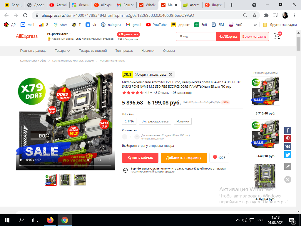
Материнская плата atermiter x79 была куплена мной на Aliexpress за 61,99$ , это примерно 4526рублей 14 декабря 2021 года.

Сейчас стоимость этой материнской платы около 6000руб
Я собирал компьютер самостоятельно и из тех комплектующих, которые были мне интересны. Собирал медленно и по частям. Почему выбор пал именно на материнскую плату с DDR3 слотом? — ответить не смогу. Но скажу однозначно что рассматривал именно серверный процессор, поскольку десктоповские аналоги от интел(i5,i7) стоят в разы дороже. В итоге мне не хватило полной суммы и я взял к этой плате затычку в виде intel xeon e5 2620. это многоядерный проц с маленькой частотой. Но и он уже уделывал на тот момент все то, что было у меня дома.
Китайская atermiter попала ко мне на стол как необычная материнская плата для домашнего компьютера. Дело в том, что мне нужно было собрать машину для решения бытовых задач, рендеринга, программирования на Unity и новых компьютерных игр.

На материнской плате имеется 8 usb выходов(два из которых USB 3.0) и стандартные порты под мышь и клавиатуру, а также все необходимые выходы и входы для аудиоустройств.
atermiter характеристики
Материнская плата китайского изготовления atermiter x79 имеет следующие характеристики:
Процессор: LGA 2011
Оперативная практика: 4xDDR3 1866 МГц/1600 МГц/1333 МГц
а также REG ECC DDR3
3xPCI Express 3.0
1xNVME SSD
2xPCI Express x4
2xSATA 3.0
Также на плате установлены огромные радиаторы на резисторы над местом установки процессора. А еще есть удобнейшие оверклокерские кнопочки включения и Reset, которые расположены справа внизу платы.
Atermiter x79 подключение
Для того, чтобы выполнить правильное подключение платы , обязательно посмотрите все предоставленные ниже видео. Я специально пробовал по всякому подключать плату и нашел правильную схему подключения материнской платы.

Распиновка материнской платы Atermiter x79 практически ничем не отличается от любой другой. Для включения компьютера нам стандартно необходимы только два ближайших контакта Power SW, которые расположены в линии из четырех Pin. Панель, на которой расположены эти контакты, находится внизу материнской платы и именована F_panel, что означает Front panel(Передняя панель)
Для удобства подключения посмотрите видео
Далее чтобы плата хорошо и долго работала, Вам необходимо сделать правильную вентиляцию внутри системного блока. Благо, материка позволяет подключить сразу три 3Pin для подключения вентиляторов, помимо процессорного кулера.
-
Contents
-
Table of Contents
-
Bookmarks
Quick Links
Related Manuals for Asus X79-DELUXE
Summary of Contents for Asus X79-DELUXE
-
Page 1
X79-DELUXE… -
Page 2
Product warranty or service will not be extended if: (1) the product is repaired, modified or altered, unless such repair, modification of alteration is authorized in writing by ASUS; or (2) the serial number of the product is defaced or missing. -
Page 3: Table Of Contents
Contents Safety information …………………. vi About this guide ………………….vii X79-DELUXE specifications summary …………..ix Package contents ………………… xiii Installation tools and components …………….. xiv Chapter 1: Product Introduction Special features………………1-1 1.1.1 Product highlights……………. 1-1 1.1.2 Dual Intelligent Processors 4 with 4-Way Optimization ….1-2 1.1.3…
-
Page 4
3.6.8 Network Stack …………….3-32 Monitor menu ………………. 3-33 Boot menu ………………..3-36 Tool menu ………………..3-42 3.9.1 ASUS EZ Flash 2 Utility …………3-42 3.9.2 ASUS DRAM SPD Information ……….3-42 3.9.3 ASUS O.C. Profile …………..3-43 3.10 Exit menu ………………..3-44 3.11… -
Page 5
Wi-Fi Engine…………….4-21 4.4.6 Wi-Fi GO! ……………… 4-23 4.4.7 EZ Update …………….. 4-40 4.4.8 Network iControl……………. 4-42 4.3.9 ASUS SSD Caching II …………… 4-44 4.4.10 System Information …………..4-45 Audio configurations …………….4-46 Chapter 5: RAID support RAID configurations ……………… 5-1 5.1.1 RAID definitions ……………. -
Page 6: Safety Information
Safety information Electrical safety • To prevent electrical shock hazard, disconnect the power cable from the electrical outlet before relocating the system. • When adding or removing devices to or from the system, ensure that the power cables for the devices are unplugged before the signal cables are connected. If possible, disconnect all power cables from the existing system before you add a device.
-
Page 7: About This Guide
Refer to the following sources for additional information and for product and software updates. ASUS website The ASUS website (www.asus.com) provides updated information on ASUS hardware and software products. Optional documentation Your product package may include optional documentation, such as warranty flyers, that may have been added by your dealer.
-
Page 8: Conventions Used In This Guide
Conventions used in this guide To ensure that you perform certain tasks properly, take note of the following symbols used throughout this manual. DANGER/WARNING: Information to prevent injury to yourself when trying to complete a task. CAUTION: Information to prevent damage to the components when trying to complete a task IMPORTANT: Instructions that you MUST follow to complete a task.
-
Page 9: X79-Deluxe Specifications Summary
** Hyper DIMM support is subject to the physical characteristics of individual CPUs. Please refer to Memory QVL (Qualified Vendors List) for details. *** Refer to www.asus.com or this user manual for the Memory QVL (Qualified Vendors List). Expansion slots 3 x PCI Express 3.0 x16 slots (dual at x16/x16;…
-
Page 10
— 2 x USB 3.0/2.0 ports at mid-board for front panel support — 6 x USB 3.0/2.0 ports at rear panel with 1 additional ASMedia SuperSpeed USB hub controller ASUS Dual Intelligent Processors 4 — 4-Way ASUS Exclusive Features Optimization tuning key… -
Page 11
— Disk Unlocker — AI Suite 3 — Anti Surge — MemOK! ASUS Quiet Thermal Solution: — ASUS Fan Xpert 2 featuring Fan Auto Tuning function for optimized speed control — ASUS Fanless Design: Heat-pipe solution ASUS Q-Design — ASUS Q-Code… -
Page 12
4 x USB 2.0/1.1 ports (white port supports USB BIOS Flashback) 1 x USB BIOS Flashback button 2 x ASUS Wi-Fi GO! SMA antenna ports (2T2R) (Wi-Fi 802.11 a/b/g/n/ac and Bluetooth v4.0) 2 x LAN (RJ45) ports (1 x Intel LAN) ®… -
Page 13: Package Contents
Check your motherboard package for the following items ASUS X79-DELUXE motherboard User manual Support DVD 6 x Serial ATA 6Gb/s cables 1 x ASUS 3-WAY SLI™ bridge 1 x ASUS SLI™ bridge connector connector 4 x Serial ATA 3Gb/s cables 1 x 2T2R dual-band Wi-Fi moving…
-
Page 14: Installation Tools And Components
Installation tools and components 1 bag of screws Philips (cross) screwdriver PC chassis Power supply unit Intel LGA2011 CPU Intel LGA2011 compatible CPU Fan ® ® DIMM SATA hard disk drive SATA optical disc drive (optional) Graphics card The tools and components in the table above are not included in the motherboard package.
-
Page 15: Chapter 1: Product Introduction
The Intel X79 Express Chipset natively supports the next-generation SATA (Serial ATA) ® interface, delivering up to 6Gb/s data transfer. ASUS provides extra 6Gb/s ports with enhanced scalability, faster data retrieval, and double the bandwidth of current bus systems. ASUS X79-DELUXE…
-
Page 16: Dual Intelligent Processors 4 With 4-Way Optimization
TPU (Turbo Processing Unit), offers precise voltage control and advanced monitoring mechanisms through the Auto Tuning and TurboV functions in your ASUS AI Suite 3 utility. EPU (Energy Processing Unit), the world’s first real-time system power-saving chip, automatically detects the current system load and intelligently moderates power usage.
-
Page 17: Asus Exclusive Features
ASUS Exclusive Features Wi-Fi GO! ASUS Wi-Fi GO! leads the way to a more enjoyable home entertainment. With ASUS Wi-Fi GO!, you can wirelessly stream media files to DLNA devices, remotely control and access your computer using your smart device and easily transfer files between your computer and smart device.
-
Page 18: Asus Quiet Thermal Solution
The heatsink design also lowers the temperature of the chipset and power phase area through high efficient heat-exchange. Combined with usability and aesthetics, the ASUS stylish heatsink will give you an extremely silent and cooling experience with its elegant appearance.
-
Page 19: Other Special Features
ASUS Q-connector ASUS Q-Connector is a unique adapter that allows you to easily connect or disconnect the chassis front panel cables to one module, eliminating the hassle of plugging one cable at a time and making the connection quick and accurate.
-
Page 20: Motherboard Overview
Motherboard overview 1.2.1 Before you proceed Take note of the following precautions before you install motherboard components or change any motherboard settings. • Unplug the power cord from the wall socket before touching any component. • Before handling components, use a grounded wrist strap or touch a safely grounded object or a metal object, such as the power supply case, to avoid damaging them due to static electricity.
-
Page 21: Motherboard Layout
1.2.2 Motherboard layout Refer to 1.2.8 Internal connectors and 2.3.1 Rear I/O connection for more information about rear panel connectors and internal connectors. ASUS X79-DELUXE…
-
Page 22: Layout Contents
Layout contents Connectors/Jumpers/Buttons and switches/Slots Page 1. DDR3 DIMM slots 1-10 2. ATX power connectors (24-pin EATXPWR, 8-pin EATX12V) 1-44 3. LGA2011 CPU socket 4. CPU, CPU optional, and chassis fan connectors (4-pin CPU_FAN, 1-42 4-pin CPU_OPT, 4-pin CHA_FAN1-4 ) 5.
-
Page 23: Central Processing Unit (Cpu)
Contact your retailer immediately if the PnP cap is missing, or if you see any damage to the PnP cap/socket contacts/motherboard components. ASUS will shoulder the cost of repair only if the damage is shipment/ transit-related.
-
Page 24: System Memory
1.2.4 System memory The motherboard comes with eight Double Data Rate 3 (DDR3) Dual Inline Memory Modules (DIMM) slots. A DDR3 module is notched differently from a DDR or DDR2 module. DO NOT install a DDR or DDR2 memory module to the DDR3 slot. Recommended memory configurations Chapter 1: Product introduction 1-10…
-
Page 25: Memory Configurations
Always install the DIMMS with the same CAS Latency. For an optimum compatibility, we recommend that you install memory modules of the same version or data code (D/ C) from the same vendor. Check with the vendor to get the correct memory modules. ASUS X79-DELUXE 1-11…
-
Page 26
X79-DELUXE Motherboard Qualified Vendors List (QVL) DDR3 2400 MHz capacity Vendors Part No. Size Chip Chip Timing Voltage DIMM socket support Brand (Optional) A-DATA AX3U2400GW8G11(XMP) 16GB 11-13- 1.65 • • • (2x8GB) 13-35 Apacer 78.BAGFL.AFD0C(XMP) 11-12- • (2x4GB) 12-30 Apacer 783BAGF3.AFD0C(XMP) -
Page 27
TX2133KLH-16GK 16GB (2x8GB) 2133-10-11- • (XMP) 10-27 Transcend TX2133KLN-8GK 8GB (2x4GB) 2133-10-11- • (XMP) 10-27 Team TLD38G2133HC11 16GB (2x8GB) 11-11-11-31 1.65 • • • • ABK(XMP) Team TLD34G2133HC1 8GB (2x4GB) 11-11-11-31 1.65 • • • • 1ABK(XMP) ASUS X79-DELUXE 1-13… -
Page 28
DDR3 2000 MHz capacity Vendors Part No. Size Chip Chip NO. Timing Voltage DIMM socket support Brand (Optional) GEIL GUP34GB2000C9DC 4GB (2x2GB) 9-9-9-28 1.65 • • • • (XMP) AEXEA AXA3ES4GK2000LG28 4GB (2x2GB) 1.65 • • V(XMP) Asint SLA302G08-ML2HB Hynix H5TQ2G8 9-9-9-27 •… -
Page 29
• • • HC10SBK(XMP) Team TED34GM18 6 Hynix H5TC2G 13-13-13-32 • • • • 6C13BK 83EFR Team TLD34G1866 8GB (2x4GB) 9-11-9-27 • • • • HC9KBK(XMP) Team TED38GM1 Hynix H5TQ4G 13-13-13-32 • • • • 866C13BK 83AFR ASUS X79-DELUXE 1-15… -
Page 30
DDR3 1600 MHz capacity Vendors Part No. Size SS/DS Chip Chip NO. Timing Voltage DIMM socket support Brand (Optional) A-DATA AD3U1600C2G11 MICRON D9PFJ 11-11- • • • 11-28 A-DATA AD3U1600W4G11 A-DATA 3WCD- 11-11- • • • 1211A 11-28 A-DATA AX3U1600GW8 16GB (2x8GB) 9-9-9- •… -
Page 31
SAMSUNG K4B4G 11-11- • • 0846B 11-28-2 Transcend JM1600KLH- Transcend TK963 • • 8G(626633) EBF3 Transcend TS1GLK64V6 SAMSUNG K4B4G • • H(620945) 0846B Transcend TS1GLK64W6H SAMSUNG K4B4G 11-11- • • 0846B 11-28-1 (Continued on the next page) ASUS X79-DELUXE 1-17… -
Page 32
DDR3 1600 MHz capacity Vendors Part No. Size SS/DS Chip Chip NO. Timing Voltage DIMM socket support Brand (Optional) AE32G1609U1-U 23EY4587MB6H • • • Asint SLZ302G08- ASint 302G08-GN1C • • • EGN1C Asint SLA304G08- Asint 304G08-GN1B 9-11- • • • ENG1B 11-28 Asint… -
Page 33
MICRON D9QBJ • • H(620053) AE32G1339U1-U 23EY4587MB3H • • • AE34G1339U2-U 23EY4587MB3H • • Asint SLA302G08- ASint 302G08-DJ1C • • • EDJ1C Asint SLA304G08- Asint 304G08-DJ1B 9-10- • • • EDJ1B 10-26 (Continued on the next page) ASUS X79-DELUXE 1-19… -
Page 34
DDR3 1600 MHz capacity Vendors Part No. Size SS/DS Chip Chip NO. Timing Voltage DIMM socket support Brand (Optional) Asint SLZ302G08- ASint 302G08-DJ1C • • • EDJ1C Asint SLB304G08- Asint 304G08-DJ1B 9-9-9- • • • EDJ1B BUFFALO D3U1333-1G Elpida J1108BFBG- •… -
Page 35
ASUS exclusively provides hyper DIMM support function. • Hyper DIMM support is subject to the physical characteristics of individual CPUs. Load the X.M.P. or D.O.C.P. settings in the BIOS for the hyper DIMM support. • Visit the ASUS website for the latest QVL. ASUS X79-DELUXE 1-21… -
Page 36: Expansion Slots
1.2.5 Expansion slots Unplug the power cord before adding or removing expansion cards. Failure to do so may cause you physical injury and damage motherboard components. Slot No. Slot Description PCIe 3.0 x16_1 slot PCIe 2.0 x1_1 slot PCIe 3.0 x16_2 slot PCIe 3.0 x16_3 slot (at x4 mode) PCIe 3.0 x16_4 slot PCIe 2.0 x1_2 slot…
-
Page 37
Controller 1 ASMedia USB 3.0 – shared – – – – – – Controller 2 ASMedia USB 3.0 – – shared – – – – – Controller 3 Realtek – shared – – – – – – ® ASUS X79-DELUXE 1-23… -
Page 38: Onboard Buttons And Switches
1.2.6 Onboard buttons and switches Onboard buttons and switches allow you to fine-tune performance when working on a bare or open-case system. This is ideal for overclockers and gamers who continually change settings to enhance system performance. Power-on button The motherboard comes with a power-on button that allows you to power up or wake up the system.
-
Page 39
BIOS default settings. A message will appear during POST reminding you that the BIOS has been restored to its default settings. • We recommend that you download and update to the latest BIOS version from the ASUS website at www.asus.com after using the MemOK! function. ASUS X79-DELUXE 1-25… -
Page 40
DirectKey button This feature allows your system to go to the BIOS Setup program with the press of a button. With DirectKey, you can enter the BIOS anytime without having to press the <Delete> key during POST. It also allows you to turn on or turn off your system and conveniently enter the BIOS during boot-up. -
Page 41
You may use the 4-Way Optimization and TPU feature in the AI Suite 3 application, adjust the BIOS setup program or enable the TPU switch at the same time. However, the system will use the last setting you have made. ASUS X79-DELUXE 1-27… -
Page 42
EPU switch Enable this switch to automatically detect the current PC loadings and intelligently moderate the power consumption. Enable this switch when the system is powered off. • The EPU LED (OLED2) near the EPU switch lights up when the EPU switch is enabled. -
Page 43
Clear CMOS button Press this button to clear the BIOS setup information only when the systems hangs due to overclocking. ASUS X79-DELUXE 1-29… -
Page 44: Onboard Leds
1.2.7 Onboard LEDs POST State LEDs The POST State LEDs provide the status of these key components during POST (Power-On-Self Test): CPU, memory modules, VGA card, and hard disk drives. If an error is found, the critical component’s LED stays lit up until the problem is solved. TPU LED The TPU LED lights up when the TPU switch is enabled.
-
Page 45
The EPU LED lights up when the EPU switch is enabled. Q-Code LEDs The Q-Code LED design provides you with a 2-digit error code that displays the system status. Refer to the Q-Code table on the next page for details. ASUS X79-DELUXE 1-31… -
Page 46
Q-Code table Code Description Not used Power on. Reset type detection (soft/hard). AP initialization before microcode loading System Agent initialization before microcode loading PCH initialization before microcode loading Microcode loading AP initialization after microcode loading System Agent initialization after microcode loading PCH initialization after microcode loading Cache initialization 0C –… -
Page 47
PCI Bus Hot Plug Controller Initialization PCI Bus Enumeration PCI Bus Request Resources PCI Bus Assign Resources Console Output devices connect Console input devices connect Super IO Initialization USB initialization is started USB Reset (continued on the next page) ASUS X79-DELUXE 1-33… -
Page 48
Code Description USB Detect USB Enable 9E – 9F Reserved for future AMI codes IDE initialization is started IDE Reset IDE Detect IDE Enable SCSI initialization is started SCSI Reset SCSI Detect SCSI Enable Setup Verifying Password Start of Setup Reserved for ASL (see ASL Status Codes section below) Setup Input Wait Reserved for ASL (see ASL Status Codes section below) -
Page 49
System is waking up from the S3 sleep state System is waking up from the S4 sleep state System has transitioned into ACPI mode. Interrupt controller is in PIC mode. System has transitioned into ACPI mode. Interrupt controller is in APIC mode. ASUS X79-DELUXE 1-35… -
Page 50: Internal Connectors
1.2.8 Internal connectors Intel X79 Serial ATA 6Gb/s connectors (7-pin SATA6G_1/2 [black] ® These connectors connect to Serial ATA 6Gb/s hard disk drives via Serial ATA 6Gb/s signal cables. If you installed Serial ATA hard disk drives, you can create a RAID 0, 1, 5, and 10 configuration with the Intel Rapid Storage Technology through the onboard Intel ®…
-
Page 51
Serial ATA 6Gb/s connectors (7-pin SATA6G_E56 [dark brown]) ® These connectors connect to Serial ATA 6Gb/s hard disk drives via Serial ATA 6Gb/s signal cables. • ASMedia storage controller can only support AHCI mode. • These SATA ports are for data drives only. ASUS X79-DELUXE 1-37… -
Page 52
Intel Serial ATA 3Gb/s connectors (7-pin SATA3G_3-6 [black]) ® These connectors connect to Serial ATA 3Gb/s hard disk drives and optical drives via Serial ATA 3Gb/s signal cables. If you installed Serial ATA hard disk drives, you can create a RAID 0, 1, 5, and 10 configuration with the Intel Rapid Storage Technology through the onboard Intel ®… -
Page 53
The signal is then generated as a chassis intrusion event. By default, the pin labeled “Chassis Signal” and “Ground” are shorted with a jumper cap. Remove the jumper caps only when you intend to use the chassis intrusion detection feature. ASUS X79-DELUXE 1-39… -
Page 54
USB 3.0 connector (20-1 pin USB3_78) This connector allows you to connect a USB 3.0 module for additional USB 3.0 front or rear panel ports. With an installed USB 3.0 module, you can enjoy all the benefits of USB 3.0 including faster data transfer speeds of up to 5Gbps, faster charging time for USB-chargeable devices, optimized power efficiency, and backward compatibility with USB 2.0. -
Page 55
DO NOT connect a 1394 cable to the USB connectors. Doing so will damage the motherboard! You can connect the front panel USB cable to the ASUS Q-Connector (USB) first, and then install the Q-Connector (USB) to the USB connector onboard if your chassis supports front panel USB ports. -
Page 56
Ensure that the CPU fan cable is securely installed to the CPU fan connector. • The CPU_FAN connector supports the CPU fan of maximum 1A (12 W) fan power. • The CPU_FAN connector and CHA_FAN connectors support the ASUS FAN Xpert 2 feature. Chapter 1: Product introduction 1-42… -
Page 57
• If you want to connect a high-definition or an AC’97 front panel audio module to this connector, set the Front Panel Type item in the BIOS setup to [HD] or [AC97]. ASUS X79-DELUXE 1-43… -
Page 58
1000W power or above to ensure the system stability. • If you are uncertain about the minimum power supply requirement for your system, refer to the Recommended Power Supply Wattage Calculator at http://support.asus. com/PowerSupplyCalculator/PSCalculator.aspx?SLanguage=en-us for details. Chapter 1: Product introduction… -
Page 59: System Panel Connector 20-8 Pin Panel
Pressing the power switch for more than four seconds while the system is ON turns the system OFF. • Reset button (2-pin RESET) This 2-pin connector is for the chassis-mounted reset button for system reboot without turning off the system power. ASUS X79-DELUXE 1-45…
-
Page 60
TPM connector (20-1 pin TPM) This connector supports a Trusted Platform Module (TPM) system, which securely store keys, digital certificates, passwords and data. A TPM system also helps enhance network security, protect digital identities, and ensures platform integrity. DirectKey connector (2-pin DRCT) This connector is for the chassis-mounted button that supports the DirectKey function. -
Page 61: Chapter 2: Basic Installation
The diagrams in this section are for reference only. The motherboard layout may vary with models, but the installation steps are the same for all models. Install the ASUS Q-Shield to the chassis rear I/O panel. Place the motherboard into the chassis, ensuring that its rear I/O ports are aligned to the chassis’…
-
Page 62
Place nine screws into the holes indicated by circles to secure the motherboard to the chassis. DO NOT overtighten the screws! Doing so can damage the motherboard. Chapter 2: Basic installation… -
Page 63: Cpu Installation
Take note of the order in opening and/or closing the double latch. Follow the instructions printed on the metal sealing hatch or the illustrations shown below in this manual. The plastic cap pops up automatically once the CPU is in place and the hatch is properly sealed down. Load lever ASUS X79-DELUXE…
-
Page 64
Triangle mark Triangle mark Chapter 2: Basic installation… -
Page 65: Cpu Heatsink And Fan Assembly Installation
2.1.3 CPU heatsink and fan assembly installation Apply the Thermal Interface Material to the CPU heatsink and CPU before you install the heatsink and fan, if necessary. To install the CPU heatsink and fan assembly ASUS X79-DELUXE…
-
Page 66: Dimm Installation
2.1.4 DIMM installation To remove a DIMM Chapter 2: Basic installation…
-
Page 67: Atx Power Connection
2.1.5 ATX Power connection ASUS X79-DELUXE…
-
Page 68: Sata Device Connection
2.1.6 SATA device connection Chapter 2: Basic installation…
-
Page 69: Front I/O Connector
2.1.7 Front I/O Connector To install ASUS Q-Connector To install USB 2.0 connector To install front panel audio connector AAFP USB 2.0 To install USB 3.0 connector USB 3.0 ASUS X79-DELUXE…
-
Page 70: Expansion Card Installation
2.1.8 Expansion Card installation To install PCIe x16 cards To install PCIe x1 cards Chapter 2: Basic installation 2-10…
-
Page 71: Wi-Fi Antenna Installation
2.1.9 Wi-Fi antenna installation Installing the ASUS 2T2R dual band W-Fi antenna Connect the bundled ASUS 2T2R dual band Wi-Fi antenna connector to the Wi-Fi ports at the back of the chassis. IO Shield • Ensure that the ASUS 2T2R dual band Wi-Fi antenna is securely installed to the Wi-Fi ports.
-
Page 72: Bios Update Utility
• Updating BIOS may have risks. If the BIOS program is damaged during the process and results to the system’s failure to boot up, please contact your local ASUS Service Center. Chapter 2: Basic installation…
-
Page 73: Motherboard Rear And Audio Connections
USB 3.0 ports 3-4 USB 3.0 ports 5-6 Optical S/PDIF Out port Audio I/O ports*** *, ** and ***: Refer to the tables on the next page for Bluetooth/Wi-Fi module LEDs, LAN port LEDs, and audio port definitions. ASUS X79-DELUXE 2-13…
-
Page 74
• USB 3.0 devices can only be used as data storage only. • We strongly recommend that you connect USB 3.0 devices to USB 3.0 ports for faster and better performance for your USB 3.0 devices. • When using the external SATA port, ensure that you use a compatible connector. *Bluetooth and Wi-Fi module LED indications Wi-Fi LED Bluetooth LED… -
Page 75: Audio I/O Connections
2.3.2 Audio I/O connections Audio I/O ports Connect to Headphone and Mic Connect to Stereo Speakers ASUS X79-DELUXE 2-15…
-
Page 76
Connect to 2.1 channel Speakers Connect to 4.1 channel Speakers Connect to 5.1 channel Speakers Chapter 2: Basic installation 2-16… -
Page 77: Starting Up For The First Time
If you do not see anything within 30 seconds from the time you turned on the power, the system may have failed a power-on test. Check the jumper settings and connections or call your retailer for assistance. ASUS X79-DELUXE 2-17…
-
Page 78: Turning Off The Computer
BIOS Beep Description One short beep VGA detected Quick boot set to disabled No keyboard detected One continuous beep followed by two No memory detected short beeps then a pause (repeated) One continuous beep followed by three No VGA detected short beeps One continuous beep followed by four Hardware component failure…
-
Page 79: Chapter 3: Bios Setup
BIOS setup Knowing BIOS The new ASUS UEFI BIOS is a Unified Extensible Interface that complies with UEFI architecture, offering a user-friendly interface that goes beyond the traditional keyboard- only BIOS controls to enable a more flexible and convenient mouse input. You can easily navigate the new UEFI BIOS with the same smoothness as your operating system.
-
Page 80: Bios Setup Program
BIOS setup program Use the BIOS Setup to update the BIOS or configure its parameters. The BIOS screen include navigation keys and brief onscreen help to guide you in using the BIOS Setup program. Entering BIOS at startup To enter BIOS Setup at startup, press <Delete> during the Power-On Self Test (POST). If you do not press <Delete>, POST continues with its routines.
-
Page 81: Ez Mode
• The boot device options vary depending on the devices you installed to the system. • The Boot Menu (F8) button is available only when the boot device is installed to the system. ASUS X79-DELUXE…
-
Page 82: Advanced Mode
3.2.2 Advanced Mode The Advanced Mode provides advanced options for experienced end-users to configure the BIOS settings. The figure below shows an example of the Advanced Mode. Refer to the following sections for the detailed configurations. To access the Advanced Mode, click Exit, then select Advanced Mode or press F7 hotkey. Menu bar General help Back button…
-
Page 83: Menu Items
This button allows you to enter notes of the activities that you have done in BIOS. • The Quick Note function does not support the following keyboard functions: delete, cut, copy and paste. • You can only use the alphanumeric characters to enter your notes. ASUS X79-DELUXE…
-
Page 84: My Favorites
Last Modified button This button shows the items that you last modified and saved in BIOS Setup. My Favorites MyFavorites is your personal space where you can easily save and access your favorite BIOS items. Adding items to My Favorites To add frequently-used BIOS items to My Favorites: Use the arrow keys to select an item that you want to add.
-
Page 85: Main Menu
RTC RAM via the Clear CMOS button. The Administrator or User Password items on top of the screen show the default [Not • Installed]. After you set a password, these items show [Installed]. ASUS X79-DELUXE…
-
Page 86: Administrator Password
Administrator Password If you have set an administrator password, we recommend that you enter the administrator password for accessing the system. Otherwise, you might be able to see or change only selected fields in the BIOS setup program. To set an administrator password: Select the Administrator Password item and press <Enter>.
-
Page 87: Ai Tweaker Menu
Be cautious when changing the settings of the Ai Tweaker menu items. Incorrect field values can cause the system to malfunction. The configuration options for this section vary depending on the CPU and DIMM model you installed on the motherboard. Scroll down to display other BIOS items. ASUS X79-DELUXE…
-
Page 88
Ai Overclock Tuner [Auto] Allows you to select the CPU overclocking options to achieve the desired CPU internal frequency. Select any of these preset overclocking configuration options: [Auto] Loads the optimal settings for the system. [Manual] Allows you to automatically optimize the CPU ratio and BCLK frequency. [X.M.P.] Allows your system to automatically optimize the CPU ratio, BCLK frequency, and memory parameters. -
Page 89
The following item appears only when you set the EPU Power Saving Mode to [Enabled]. EPU Setting [Auto] Allows you to select a fixed setting for the EPU power saving mode. Configuration options: [Auto] [Light Power Saving Mode] [Medium Power Saving Mode] [Max Power Saving Mode] ASUS X79-DELUXE 3-11… -
Page 90: Dram Timing Control
DRAM Timing Control The subitems in this menu allow you to set the DRAM timing control features. Use the <+> or <-> keys to adjust the value. To restore the default setting, type [auto] using the keyboard and press the <Enter> key. Changing the values in this menu may cause the system to become unstable! If this happens, revert to the default settings.
-
Page 91
Configuration options: [Auto] [Advance 14 Clock] [Advance 12 Clock] [Advance 10 Clock] [Advance 8 Clock] [Advance 6 Clock] [Advance 4 Clock] [Advance 2 Clock] [Normal] [Delay 2 Clock] [Delay 4 Clock] [Delay 6 Clock] [Delay 8 Clock] [Delay 10 Clock] [Delay 12 Clock] [Delay 14 Clock] ASUS X79-DELUXE 3-13… -
Page 92
DRAM IOL (CHA D1 R0; CHB D1 R0; CHC D1 R0; CHD D1 R0) [Auto] Configuration options: [Auto] [Advance 1 Clock] — [Advance 14 Clock] [Normal] [Delay 1 Clock] — [Delay 14 Clock] DRAM RTL (CHA D1 R1; CHB D1 R1; CHC D1 R1; CHD D1 R1) [Auto] Configuration options: [Auto] [Advance 14 Clock] [Advance 12 Clock] [Advance 10 Clock] [Advance 8 Clock] [Advance 6 Clock] [Advance 4 Clock] [Advance 2 Clock] [Normal] [Delay 2 Clock] [Delay 4 Clock] [Delay 6 Clock] [Delay 8 Clock] [Delay 10… -
Page 93
Set a higher value for a better overclocking performance of the VCCSA voltage at initial boot. Use the <+> or <-> keys to adjust the value. The values range from 0.800kHz to 1.7kHz with a 0.005kHz interval. ASUS X79-DELUXE 3-15… -
Page 94
CPU Voltage Frequency [Auto] Frequency switching affects the VRM transient response and the thermal component conditions. Higher frequency gets quicker transient response. Configuration options: [Auto] [Manual] DO NOT remove the thermal module when setting this item to [Manual]. The thermal conditions should be monitored. -
Page 95
DRAM-AB Power Phase Control [Standard] [Standard] Allows you to set the Auto mode. [Optimized] Allows you to set the ASUS optimized phase tuning profile. [Extreme] Allows you to set the full phase mode. DRAM-CD Current Capability [100%] Set a higher value for a total power range of DRAM slots C and D, and extends the overclocking frequency range simultaneously. -
Page 96: Cpu Performance Settings
CPU Performance Settings The subitems in this menu allow you to set the CPU ratio and their features. Enhanced Intel SpeedStep Technology [Enabled] Allows the operating system to dynamically adjust the processor voltage and cores frequency, resulting to a decreased average power consumption and decreased average heat production.
-
Page 97
CPU PLL Voltage [Auto] Allows you to configure the voltage amount for the processor’s phase locked loop (PLL). Use the <+> or <-> keys to adjust the value. The values range from 1.200V to 1.990V with a 0.005V interval. ASUS X79-DELUXE 3-19… -
Page 98
VTTCPU Voltage [Auto] Allows you to configure the voltage amount for the processor’s cores and cache. Use the <+> or <-> keys to adjust the value. The values range from 1.05000V to 1.70000V with a 0.003125V interval. PCH 1.1v Voltage [Auto] Allows you to configure the voltage amount for the PCH chipset. -
Page 99
CPU Spread Spectrum [Auto] [Auto] Automatic configuration. [Disabled] Enhances the BCLK overclocking ability. [Enabled] Sets to [Enabled] for EMI control. PCIE Spread Spectrum [Auto] [Auto] Automatic configuration. [Disabled] Enhances the PCIE overclocking ability. [Enabled] Sets to [Enabled] for PCIE control. ASUS X79-DELUXE 3-21… -
Page 100: Advanced Menu
Advanced menu The Advanced menu items allow you to change the settings for the CPU and other system devices. Be cautious when changing the settings of the Advanced menu items. Incorrect field values can cause the system to malfunction. Chapter 3: BIOS setup 3-22…
-
Page 101: Cpu Configuration
Configuration options: [All] [1] [2] [3] [4] [5] Limit CPUID Maximum [Disabled] When set to [Enabled], this item allows the legacy OS to boot even without support for CPUs with extended CPUID functions. Configuration options: [Enabled] [Disabled] ASUS X79-DELUXE 3-23…
-
Page 102
Execute Disable Bit [Enabled] Execute Disable prevents certain classes of malicious buffer overflow attacks when combined with a supporting OS (SuSE Linux 9.2, RedHat Enterprise 3 Update 3). Configuration options: [Disabled] [Enabled] Intel Virtualization Technology [Enabled] When set to [Enabled], a VMM can utilize the additional hardware capabilities provided by Vanderpool Technology. -
Page 103: System Agent Configuration
PCIEX16_3 Link Speed [GEN3] Allows you to select a target link speed in this slot. Configuration options: [GEN1] [GEN2] [GEN3] 3.6.3 PCH Configuration High Precision Timer [Enabled] Allows you to enable the High Precision Event Timer. Configuration options: [Disabled] [Enabled] ASUS X79-DELUXE 3-25…
-
Page 104: Sata Configuration
3.6.4 SATA Configuration While entering Setup, the BIOS automatically detects the presence of SATA devices. The SATA Port items show Not Present if no SATA device is installed to the corresponding SATA port. Scroll down to display the other BIOS items. SATA Mode Selection [AHCI] Allows you to set the SATA configuration.
-
Page 105: Usb Configuration
Allows you to enable or disable the support for USB 3.0 devices. Configuration options: [Disabled] [Enabled] EHCI Hand-off [Disabled] [Enabled] Enables the support for operating systems without an EHCI hand-off feature. [Disabled] Disables the EHCI Hand-off support. ASUS X79-DELUXE 3-27…
-
Page 106: Onboard Devices Configuration
USB Per Port Control Allows you to enable or disable the individual USB port. Refer to section 1.2.2 Motherboard layout for the location of the USB ports. 3.6.6 Onboard Devices Configuration Scroll down to view the other BIOS items. Azalia HD Audio [Enabled] [Enabled] Enables the Azalia Audio Controller.
-
Page 107
Disables the system to run at x1 link when eSATA mode is enabled. ASMedia USB 3.0 Controller (Rear) [Enabled] Allows you to enable the ASMedia USB 3.0 controller of the rear panel of your system. ® Configuration options: [Disabled] [Enabled] ASUS X79-DELUXE 3-29… -
Page 108
ASMedia USB 3.0 Controller (Rear) [Front] Allows you to enable the ASMedia USB 3.0 controller of the front panel of your system. ® Configuration options: [Disabled] [Enabled] ASMedia USB 3.0 Battery Charging Support [Front] Allows you to enable the ASMedia USB 3.0 battery charging support of your system. -
Page 109: Apm
Allows you to switch off some power at S4+S5 or S5 to get the system ready for ErP requirement. When set to [Enabled], all other PME options will be switched off. Configuration options: [Disabled] [Enabled (S4+S5] [Enabled (S5)] ASUS X79-DELUXE 3-31…
-
Page 110: Network Stack
3.6.8 Network Stack Network stack [Disable] This item allows user to disable or enable the UEFI network stack. Configuration options: [Disable] [Enable] The following item appears only when you set the Network Stack to [Enabled]. Ipv4/Ipv6 PXE Support [Enabled] Allows you to enable or disable the Ipv4/Ipv6 PXE boot option. Configuration options: [Disabled] [Enabled] PXE boot wait time [0] This item allows you to key in a waiting time in pressing ESC key to abort the PXE boot.
-
Page 111: Monitor Menu
N/A. Select [Ignore] if you do not wish to display the detected speed. CPU Voltage, 3.3V Voltage, 5V Voltage, 12V Voltage The onboard hardware monitor automatically detects the voltage output through the onboard voltage regulators. Select [Ignore] if you do not want to detect this item. ASUS X79-DELUXE 3-33…
-
Page 112
CPU Q-Fan Control [Auto] Allows you to set the CPU Q-Fan operating mode. [Advance Detects the type of CPU fan installed and automatically switches the Mode] mode control. When a 3-pin CPU fan is installed, select this mode for the DC mode Q-Fan control. -
Page 113
Configuration options: [Disabled] [Enabled] Chassis Intrude Detect Support [Disabled] This item allows you to enable or disable the support for chassis intrusion detection. Enable this item to detect removal or replacement of chassis components. Configuration options: [Disabled] [Enabled] ASUS X79-DELUXE 3-35… -
Page 114: Boot Menu
Boot menu The Boot menu items allow you to change the system boot options. Boot Configuration Fast Boot [Enabled] [Disabled] Allows your system to go back to its normal boot speed. [Enabled] Allows your system to accelerate the boot speed. The following items appear only when you set the Fast Boot to [Enabled].
-
Page 115
Set the power-on state of the NumLock to [On]. [On] Set the power-on state of the NumLock to [Off]. [Off] Wait For ‘F1’ If Error [Enabled] [Disabled] Disables the function. [Enabled] The system waits for the <F1> key to be pressed when error occurs. ASUS X79-DELUXE 3-37… -
Page 116
Option ROM Messages [Force BIOS] [Force BIOS] The third-party ROM messages will be displayed during the boot sequence. [Keep Current] The third-party ROM messages will be displayed only if the third-party manufacturer had set the add-on device to do so. Setup Mode [EZ Mode] [Advanced Mode] Allows you to go to Advanced Mode of the BIOS after POST. -
Page 117: Secure Boot
Secure Boot keys will not be active. Configuration options: [Yes] [No] Load PK from File Allows you to load the downloaded PK from a USB storage device. The PK file must be formatted as a UEFI variable structure with time-based authenticated variable. ASUS X79-DELUXE 3-39…
-
Page 118
KEK Management The KEK (Key-exchange Key or Key Enrollment Key) manages the Signature database (db) and Revoked Signature database (dbx). Key-exchange Key (KEK) refers to Microsoft Secure Boot Key-Enrollment Key (KEK). ® Delete the KEK Allows you to delete the KEK from your system. Configuration options: [Yes] [No] Load KEK from File Allows you to load the downloaded KEK from a USB storage device. -
Page 119: Boot Option Priorities
® 8 not supported). • To select the boot device during system startup, press <F8> when ASUS Logo appears. Boot Override These items displays the available devices. The number of device items that appears on the screen depends on the number of devices installed in the system. Click an item to start booting from the selected device.
-
Page 120: Tool Menu
3.9.1 ASUS EZ Flash 2 Utility Allows you to run ASUS EZ Flash 2. When you press <Enter>, a confirmation message appears. Use the left/right arrow key to select between [Yes] or [No], then press <Enter> to confirm your choice.
-
Page 121: Asus O.c. Profile
3.9.3 ASUS O.C. Profile This item allows you to store or load multiple BIOS settings. Label Allows you to input a label of the setup profiles. Save to Profile Allows you to save the current BIOS settings to the BIOS Flash, and create a profile. Key in a profile number from one to eight, press <Enter>, and then select Yes.
-
Page 122: Exit Menu
This option allows you to exit the Setup program without saving your changes. When you select this option or if you press <Esc>, a confirmation window appears. Select Yes to discard changes and exit. ASUS EZ Mode This option allows you to enter the EZ Mode screen. Launch EFI Shell from filesystem device This option allows you to attempt to launch the EFI Shell application (shellx64.efi) from one of…
-
Page 123: Updating Bios
DVD and a USB flash disk drive. Save a copy of the original motherboard BIOS file to a USB flash disk in case you need to restore the BIOS in the future. Copy the original motherboard BIOS using the ASUS Update or BIOS Updater utilities.
-
Page 124: Asus Ez Flash
3.11.2 ASUS EZ Flash 2 ASUS EZ Flash 2 allows you to update the BIOS without having to use a bootable floppy disk or an OS-based utility. Before you start using this utility, download the latest BIOS from the ASUS website at www.asus.com.
-
Page 125: Asus Crashfree Bios
The BIOS file in the motherboard support DVD may be older than the BIOS file published on the ASUS official website. If you want to use the newer BIOS file, download the file at http://support.asus.com and save it to a USB flash drive.
-
Page 126: Asus Bios Updater
3.11.4 ASUS BIOS Updater The ASUS BIOS Updater allows you to update the BIOS in DOS environment. This utility also allows you to copy the current BIOS file that you can use as a backup when the BIOS fails or gets corrupted during the updating process.
-
Page 127
Press <Tab> to switch between screen fields and use the <Up/Down/Home/End> keys to select the BIOS file and press <Enter>. BIOS Updater checks the selected BIOS file and prompts you to confirm BIOS update. Are you sure to update BIOS? ASUS X79-DELUXE 3-49… -
Page 128
Select Yes and press <Enter>. When BIOS update is done, press <ESC> to exit BIOS Updater. Restart your computer. DO NOT shut down or reset the system while updating the BIOS to prevent system boot failure! • For BIOS Updater version 1.04 or later, the utility automatically exits to the DOS prompt after updating BIOS. -
Page 129: Chapter 4: Software Support
Place the Support DVD into the optical drive. In the AutoPlay dialog box, click Run ASSETUP.EXE. If the AutoPlay dialog box does not appear, browse the contents of the support DVD and double-click or tap \binASSETUP.EXE to launch the ASUS motherboard support DVD main menu. ASUS X79-DELUXE…
-
Page 130
RAID/AHCI driver disk. Click the Contact The Utilities tab to display the menu shows the ASUS contact applications and information. other software that the motherboard supports. Click an icon… -
Page 131: Obtaining The Software Manuals
Reader from the Utilities tab before opening the files. Acrobat ® To read about your motherboard’s utility guide: Click Manual tab > ASUS Motherboard Utility Guide. From the Manual folder, open the folder of the software manual that you wish to read.
-
Page 132: Software Information
View the online help or readme file that came with the software application for more information. AI Suite 3 AI Suite 3 is an all-in-one interface that integrates several ASUS utilities and allows you to launch and operate these utilities simultaneously. Installing AI Suite 3 Ensure that you have an Administrator account before installing AI Suite 3 in Windows ®…
-
Page 133
Launching AI Suite 3 Windows 7 OS ® From the Desktop, click Start > All Programs > ASUS > AI Suite 3 > AI Suite 3. You can also launch AI Suite in Windows 7 by clicking on the Notification area. -
Page 134
Some functions in the AI Suite 3 main menu in this user manual may vary depending on the motherboard model. • Refer to the software manual in the support DVD or visit the ASUS website at www.asus.com for detailed software configuration. Chapter 4: Software support… -
Page 135: Dual Intelligent Processors 4 With 4-Way Optimization
Click or tap this 4-Way Optimization Click or tap to view the 4-Way button to auto-detect and tune the best Optimization report settings for your system DO NOT remove your fan during the tuning process. ASUS X79-DELUXE…
-
Page 136
Using 4-Way Optimization Click or tap the 4-Way Optimization button then click or tap Start to auto-detect the best settings based on actual usage. Click or tap to go back to Click or tap to start Click or tap to view the 4-Way Optimization auto-tuning more settings… -
Page 137: Cpu Frequency
Set the CPU Core Ratio item in BIOS to [Auto] before using the CPU Frequency in • TPU. Refer to section 3.5 Ai Tweaker menu in the BIOS chapter of this user manual for details. • The CPU Frequency bars show the status of the CPU cores, which vary with your CPU model. ASUS X79-DELUXE…
-
Page 138: Energy Processing Unit (Epu)
CPU Strap Click or tap to adjust the CPU Strap’s BCLK frequency Click or tap to apply the changes Click or tap to apply the adjustments Click or tap to undo Click or tap to load Click or tap to save the the adjustments Click or tap to go back the saved profile…
-
Page 139
Click or tap to apply the adjustments Click or tap to select a Click or tap to apply the Click or tap to undo the fan profile default settings adjustments ASUS X79-DELUXE 4-11… -
Page 140
Away Mode Tick to select Vcore downgrade Click or tap to select a fan profile Click or tap to apply the adjustments Tick to mute the Click or tap to apply the Click or tap to undo the system’s sound default settings adjustments Chapter 4: Software support… -
Page 141
CPU Voltage Frequency affects the VRM transient response and thermal conditions. Higher VRM frequency gets a quicker transient response. CPU Power Duty Control CPU Power Duty Control adjusts the current of every VRM phase and the thermal conditions of every phase component. ASUS X79-DELUXE 4-13… -
Page 142
DRAM-AB Power Phase Control For DRAM slots A or B, select Extreme for full phase mode to increase system performance or select Optimized for ASUS optimized phase tuning profile to increase the DRAM power efficiency. DRAM-CD Power Phase Control… -
Page 143: Fan Xpert 2
Click or tap to undo the changes Click or tap to apply the changes Click or tap to switch between the CPU Click or tap to go back and chassis fan screens to the previous screen ASUS X79-DELUXE 4-15…
-
Page 144
RPM Mode RPM Mode allows you to set the fan speed at its fixed value when the CPU temperature drops 75 C and below. Drag the slider up or down to adjust the fan’s speed Click or tap to undo the changes Click or tap to apply the changes… -
Page 145: Usb 3.0 Boost
• USB 3.0 Boost automatically detects the USB 3.0 devices that support UASP. For a list of UASP-supported USB 3.0 devices, visit the ASUS website at www.asus.com. • The data transfer speed varies with USB devices. For a higher data transfer performance, use a USB 3.0 device.
-
Page 146: Usb Bios Flashback
4.4.3 USB BIOS Flashback USB BIOS Flashback allows you to check and save the latest BIOS version to a USB storage device. Use this utility to quickly check for the latest available BIOS and set the BIOS download schedule. Launching USB BIOS Flashback To launch USB BIOS Flashback, click or tap on the top-right corner of the AI Suite 3 main menu, then select USB BIOS Flashback.
-
Page 147
Wait for the system to check the latest BIOS version. After the utility detects a new BIOS, from the Save to: field, click or tap select the USB flash drive, then click or tap Download. After the download is complete, click or tap OK. ASUS X79-DELUXE 4-19… -
Page 148: Ai Charger
4.4.4 Ai Charger+ Ai Charger+ allows you to fast-charge your portable BC 1.1* mobile devices on your computer’s USB port three times faster than the standard USB devices**. Launching Ai Charger+ To launch Ai Charger+, click or tap on the top-right corner of the AI Suite 3 main menu, then select Ai Charger+.
-
Page 149: Wi-Fi Engine
Using the Client Mode The Client mode allows you to connect your system to a wireless network. To use the client mode: Click or tap Client Mode to launch Network Connections. From the Network Connections window, select a network adapter. ASUS X79-DELUXE 4-21…
-
Page 150
From the list of available networks, select a network that you want to connect to. Some networks may require you to key in a password. Using the AP Mode The AP mode allows you to set your system as an access point for other wireless-enabled devices. -
Page 151: Wi-Fi Go
ASUS Wi-Fi GO! & NFC Remote If you’re using an Android smart device, download the ASUS Wi-Fi GO! & NFC Remote from Google Play. If you’re using an iOS smart device, download the ASUS Wi-Fi GO! & NFC Remote from Apple Store.
-
Page 152
• Ensure that the ASUS AI Suite 3 utility is active when using Wi-Fi GO!. Wi-Fi GO! & NFC Remote Wi-Fi GO! & NFC Remote allows you to remotely control your computer using your smart device. -
Page 153
Click or tap Cloud GO! > Enter. Log in to your cloud accounts, then click or tap Sign In. • To log in to your ASUS Webstorage account, key in your user name and password. accounts, click or tap Sign in. Cloud •… -
Page 154
Click or tap a specific icon to move, upload, rename, create folder, download, delete or refresh your cloud contents Click or tap to open a cloud storage account Tick to select contents Click or tap to sign out Click or tap to go back to Click or tap to go Click or tap to synchronize your files to back to Wi-Fi GO! -
Page 155
Tick the contents that you want to synchronize, then tap Sync Clouds. Tick the cloud storage account then tap OK. • Tick Backup to PC under (C:MyFavorite) if you want to save a backup in your computer. • Open the Wi-Fi GO! folder to view all synced files. ASUS X79-DELUXE 4-27… -
Page 156
Remote Desktop Remote Desktop allows you to remotely control your desktop in real-time using your smart device. Using Remote Desktop To use Remote Desktop: On your smart device, tap Remote Desktop > Enter. Wait for the smart device to connect with your computer. To operate Remote Desktop in Windows 7, you can select Extended Mode or Main ®… -
Page 157
Remote Desktop interface for Windows ® Tap to launch the smart device’s keypad ASUS X79-DELUXE 4-29… -
Page 158
Media Streaming Hub Media Streaming Hub allows you to stream media files to an HDTV and remotely control playback using your smart device. • When using your computer as a receiver, ensure to launch the Windows Media Player, then enable the remote control settings of the Windows Media Player. To do this, click or tap Stream then tick the items Allow remote control of my Player… -
Page 159
Using Media Streaming Hub in your smart device To use Media Streaming Hub in your smart device, tap Media Streaming Hub > Enter. Tap to select playlist Tap to select media type Tap to select a receiver ASUS X79-DELUXE 4-31… -
Page 160: File Transfer
File Transfer File Transfer allows you to transfer files between your computer and your smart device. To send files between your computer and smart device, ensure to enable the File Transfer function in your smart device. Transferring files from computer to smart device To transfer files from computer to smart device: Click or tap File Transfer >…
-
Page 161
Wi-Fi GO! & NFC Remote. Transferring files from smart device to computer To transfer files from smart device to computer: Tap File Transfer > Enter. Tick the files that you want to send to your computer, then tap Send. ASUS X79-DELUXE 4-33… -
Page 162
Smart Sensor Control Smart Sensor Control allows you to remotely control your desktop by using your smart device’s built-in sensors. • The functions of Smart Sensor Control varies with your computer’s operating system. • For Windows 7 OS, ensure to enable the Smart Sensor Control feature in your smart ®… -
Page 163
In your smart device, tap Smart Sensor Control > Enable on the virtual microphone or gyroscope functions. Tap to enable the gyroscope function Tap to select voice Tap to enable virtual quality microphone function ASUS X79-DELUXE 4-35… -
Page 164
Using Smart Sensor Control in Windows ® To use Smart Sensor Control: Click or tap Smart Sensor Control > Setting. In the Movement tab, select an action from , and dropdown fields. To save the actions as a profile, click or tap Apply & Save. To apply the actions without saving as a profile, click or tap Apply. -
Page 165
Click or tap to apply and save the settings as a profile Click or tap to go back Click or tap to go back to Click or tap to apply the to Wi-Fi GO! screen the previous screen settings ASUS X79-DELUXE 4-37… -
Page 166
Remote Keyboard & Mouse Remote Keyboard & Mouse allows you to use your smart device’s touch panel as a remote keyboard and mouse for your computer. Using Remote Keyboard & Mouse To use Keyboard & Mouse, tap Keyboard & Mouse in your smart device then tap Enter. Input field Tick to enable the left click + hold function Mouse tap area… -
Page 167
Ensure to enable the Capture & Send feature in your smart device. To do this, tap Capture & Send then tap Enable. In your smart device, tap Capture & Send then tap Enter. Tap the file then select an app that you want to open the file with. ASUS X79-DELUXE 4-39… -
Page 168: Ez Update
4.4.7 EZ Update EZ Update is a utility that allows you to automatically update your motherboard’s software, drivers and BIOS easily. With this utlity, you can also manually update the BIOS and select the boot logo that displays during POST. Launching EZ Update To launch EZ Update, click or tap on the top-right corner of the AI Suite 3 main menu,…
-
Page 169
Update main screen Click or tap to proceed the updating BIOS and boot logo After you click or tap BIOS Update button, click or tap Flash to update the BIOS and upload the boot logo in your system. ASUS X79-DELUXE 4-41… -
Page 170: Network Icontrol
4.4.8 Network iControl Network iControl is a one-stop setup network control center that allows you to manage your network bandwidth and set the bandwidth priority for your running programs. Launching Network iControl To launch Network iControl, click or tap on the top-right corner of the AI Suite 3 main menu, then select Network iControl.
-
Page 171
Click or tap to set the program as High, Normal, or Low Priority Tick to assign a schedule of your network programs to avoid network congestions Select a program from this list then click or to add to your network profile ASUS X79-DELUXE 4-43… -
Page 172: Asus Ssd Caching Ii
ASUS SSD Caching II. Using ASUS SSD Caching II Before using ASUS SSD Caching II utility, ensure that your HDDs and SSDs are connected SATA ports. Refer to 1.2 Motherboard layout for the location of the to the Marvell ®…
-
Page 173: System Information
AI Suite 3 main menu, then select System Information. Viewing the motherboard information Click or tap the MB tab to view the motherboard’s information. Viewing the CPU information Click or tap the CPU tab to view the processor’s information. ASUS X79-DELUXE 4-45…
-
Page 174: Audio Configurations
Viewing the SPD information Click or tap the SPD tab to view the memory’s information. Audio configurations The Realtek audio CODEC provides 8-channel audio capability to deliver the ultimate audio ® experience on your computer. The software provides Jack-Sensing function, S/PDIF Out support, and interrupt capability.
-
Page 175
HD Audio Manager with DTS UltraPC II for ® Windows 8 / Windows ® ® Advanced Configuration option tabs (vary with the audio devices connected) settings Set default device button Control settings panel Analog and digital connector status ASUS X79-DELUXE 4-47… -
Page 176
Analog and digital connector status • Refer to the software manual in the support DVD or visit the ASUS website at www.asus.com for detailed software configuration. • To play Blu-Ray™ disc, make sure to use an HDCP compliant monitor. -
Page 177: Chapter 5: Raid Support
With the RAID 10 configuration you get all the benefits of both RAID 0 and RAID 1 configurations. Use four new hard disk drives or use an existing drive and three new drives for this setup. ASUS X79-DELUXE…
-
Page 178: Installing Serial Ata Hard Disks
5.1.2 Installing Serial ATA hard disks The motherboard supports Serial ATA hard disk drives. For optimal performance, install identical drives of the same model and capacity when creating a disk array. To install the SATA hard disks for a RAID configuration: Install the SATA hard disks into the drive bays.
-
Page 179: Intel ® Rapid Storage Technology Option Rom Utility
The RAID BIOS setup screens shown in this section are for reference only and may not exactly match the items on your screen. The utility supports maximum four hard disk drives for RAID configuration. ASUS X79-DELUXE…
-
Page 180
Creating a RAID set To create a RAID set: From the utility main menu, select 1. Create RAID Volume and press <Enter>. The following screen appears: Intel(R) Rapid Storage Technology — Option ROM — v10.5.1.1070 Copyright(C) 2003-10 Intel Corporation. All Rights Reserved. [ CREATE VOLUME MENU ] Name: Volume0… -
Page 181
WARNING: ALL DATA ON SELECTED DISKS WILL BE LOST. Are you sure you want to create this volume? (Y/N): Press <Y> to create the RAID volume and return to the main menu, or <N> to go back to the CREATE VOLUME menu. ASUS X79-DELUXE… -
Page 182
Deleting a RAID set Be cautious when deleting a RAID set. You will lose all data on the hard disk drives when you delete a RAID set. To delete a RAID set: From the utility main menu, select 2. Delete RAID Volume and press <Enter>. The following screen appears: [ DELETE VOLUME MENU ] Name… -
Page 183: Marvell Raid Utility
Revision ID └ PD 0: ST3160812AS BIOS Version ├ 1.0.0.1028 PD 8: ST3160812AS Firmware Version: └ 2.2.0.1105 PCIe Speed Rate : 5.0Gbps Configure SATA as: AHCI Mode ▶ Help Marvell RAID on chip controller. ENTER: Operation F10: Exit/Save ESC: Return ASUS X79-DELUXE…
-
Page 184
Create a RAID Array Move the selection bar to HBA 0: Marvell 0 and press <Enter>. Select Configuration Wizard and press <Enter>. Marvell BIOS Setup (c) 2009 Marvell Technology Group Ltd. Configure->Select free disks HBA 0: Marvell 0 Port ID Virtual Disks PD ID ├… -
Page 185
BIOS Version │ 1.0.0.1028 └ PD 8: ST3160812AS Firmware Version: │ 2.2.0.1105 └ Free Physical Disks PCIe Speed Rate : 5.0Gbps Configure SATA as: AHCI Mode ▶ ▶ Help Marvell RAID on chip controller. ENTER: Operation F10: Exit/Save ESC: Return ASUS X79-DELUXE… -
Page 186
Press <F10>. The following warning message appears: Exit Do you want to exit from Marvell BIOS Setup? Press <Y> to save the RAID setting and exit the Marvell RAID utility. Delete an existing RAID Array Select the RAID array to delete and press <Enter>. Select Delete and press <Enter>. Marvell BIOS Setup (c) 2009 Marvell Technology Group Ltd. -
Page 187: Creating A Raid Driver Disk
When the Make Disk menu appears, press <1> to create a RAID driver disk. Insert a formatted floppy disk into the USB floppy disk drive, then press <Enter>. Follow the succeeding screen instructions to complete the process. ASUS X79-DELUXE 5-11…
-
Page 188: Creating A Raid Driver Disk In Windows
5.2.2 Creating a RAID driver disk in Windows ® To create a RAID driver disk in Windows ® Start Windows ® Plug the USB floppy disk drive and insert a floppy disk. Place the motherboard support DVD into the optical drive. Go to the Intel AHCI/RAID Driver menu then click Intel AHCI/RAID Driver path to open the RAID driver folder.
-
Page 189: Appendices
The use of shielded cables for connection of the monitor to the graphics card is required to assure compliance with FCC regulations. Changes or modifications to this unit not expressly approved by the party responsible for compliance could void the user’s authority to operate this equipment. ASUS X79-DELUXE…
-
Page 190: Canadian Department Of Communications Statement
IC: Canadian Compliance Statement Complies with the Canadian ICES-003 Class B specifications. This device complies with RSS 210 of Industry Canada. This Class B device meets all the requirements of the Canadian interference-causing equipment regulations. This device complies with Industry Canada license exempt RSS standard(s). Operation is subject to the following two conditions: (1) this device may not cause interference, and (2) this device must accept any interference, including interference that may cause undesired operation of the device.
-
Page 191: Rf Equipment Notices
ASUS Recycling/Takeback Services ASUS recycling and takeback programs come from our commitment to the highest standards for protecting our environment. We believe in providing solutions for you to be able to responsibly recycle our products, batteries, other components as well as the packaging materials.
-
Page 192
Bluetooth Industry Canada Statement This Class B device meets all requirements of the Canadian interference-causing equipment regulations. Cet appareil numérique de la Class B respecte toutes les exigences du Règlement sur le matériel brouilleur du Canada. NCC: Taiwan Wireless Statement Japan RF Equipment Statement KC (RF Equipment) Appendices… -
Page 193: Asus Contact Information
+1-812-282-3777 +1-510-608-4555 Web site usa.asus.com Technical Support Telephone +1-812-282-2787 Support fax +1-812-284-0883 Online support support.asus.com ASUS COMPUTER GmbH (Germany and Austria) Address Harkort Str. 21-23, D-40880 Ratingen, Germany +49-2102-959911 Web site www.asus.de Online contact www.asus.de/sales Technical Support Telephone +49-1805-010923* Support Fax…
-
Page 194
Appendices…
- Manuals
- Brands
- MACHINIST Manuals
- Computer Hardware
- X79-Z9-D7
- User manual
-
Contents
-
Table of Contents
-
Bookmarks
Quick Links
Summary of Contents for MACHINIST X79-Z9-D7
-
Page 1
X79-Z9-D7 User’s Manual… -
Page 2: Table Of Contents
Any problem, please feel free to contact us. Contents Specifications …………………….. 1 Overview of Components ……………….. 2 Install CPU & Fan……………………3 Install Memory……………………..4 Install Expansion Card…………………… 5 Back Panel Connectors………………….. 5 USB 2.0 Port…………………….5 RJ45 LAN Port……………………6 Audio Port……………………..6 PS/2 Port……………………..6 Internal Connectors……………………
-
Page 3: Specifications
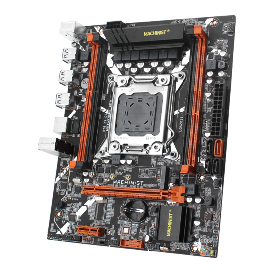
Any problem, please feel free to contact us. Specifications X79 Z9 D7 Processor Supporting Intel Xeon E5 V1/V2 and Core i7 series CPU. Southbridge X79 Chipset Technology Dual Channel DDR3 Maximum 64GB (16GB*4) Capacity Memory Slot 4 * DDR3 PS/2 Green: mouse.
-
Page 4: Overview Of Components
Any problem, please feel free to contact us. Overview of Components Package List: X79 Motherboard * 1 SATA Cable * 1 I/O Blocking * 1 CPU fan bracket * 1 — 2 —…
-
Page 5: Install Cpu & Fan
Any problem, please feel free to contact us. Install CPU & Fan Please install the CPU into the CPU socket as shown below. Important • Make sure that the motherboard supports the CPU. • Always unplug the power cord from the power outlet before installing or removing the CPU to prevent hardware damage.
-
Page 6: Install Memory
Any problem, please feel free to contact us. Install Memory The motherboard provides 4 DDR3 ECC DIMM slots with a maximum capacity of 64GB. 1. Wrench the latches on both sides of the memory slot outwards. 2. Insert the memory into the slot by aligning it with the notch in the slot. 3.
-
Page 7: Install Expansion Card
Any problem, please feel free to contact us. Install Expansion Card The motherboard provides a PCI Express 3.0 X16 expansion slot. Place the expansion card in an available PCI Express slot and press the expansion card until it is fully inserted into the slot. Important •…
-
Page 8: Rj45 Lan Port
Any problem, please feel free to contact us. RJ45 LAN Port The Gigabit Ethernet LAN port provides Internet connection at up to 1000Mbps/s data rate. The following describes the states of the LAN port LEDs. Audio Port Line-in Port The line in jack. Use this audio jack for line in devices such as an optical drive, walkman, etc. Line-out Port The line out jack.
-
Page 9: Internal Connectors
Any problem, please feel free to contact us. Internal Connectors F_PANEL1 Connector SPEAK1 Connector JAUDIO1 Connector This connector allows you to connect audio jacks on the front panel. Important • An incorrect connection between the module connector and the motherboard header will make the device unable to work or even damage it.
-
Page 10: Sata 2.0 Slots And 1* Sata 3.0 Slots
Any problem, please feel free to contact us. 3* SATA 2.0 slots and 1* SATA 3.0 slots These SATA 3.0 connectors are SATA 6Gb/s interface ports. Each SATA connector supports a single SATA device. M.2 Slot Insert your M.2 SSD into the M.2 slot at a 30-degree angle. Secure the M.2 SSD in place with the screw.
-
Page 11: Jcom1: Serial Port Connector
Any problem, please feel free to contact us. JCOM1: Serial Port Connector The COM connector can provide one serial port via an optional COM port cable. ATXPWR1, JATXPWR1: Power Connectors With the use of the power connector, the power supply can provide enough stable power to all the components on the motherboard.
-
Page 12: Cpu_Fan1, Sys_Fan1~3: Fan Connectors
Any problem, please feel free to contact us. CPU_FAN1, SYS_FAN1~3: Fan Connectors CPU_FAN is a interface for CPU radiator. The 4pin fan has PWM intelligent speed regulation function, which can intelligently control the fan speed based on load and temperature changes.
-
Page 13: Bios Setup
Any problem, please feel free to contact us. BIOS Setup BIOS (Basic Input and Output System) records hardware parameters of the system in the CMOS on the motherboard. BIOS identifies, configures, tests and connects computer hardware to the OS immediately after a computer is turned on. Its major functions include conducting the Power-On Self-Test (POST) during system startup, saving system parameters and loading the operating system, etc.
-
Page 14: Enter Bios Setup
Any problem, please feel free to contact us. Enter BIOS Setup Entering BIOS Setup When the computer starts up, BIOS enters the self-test process. When the self-test is completed, the following message is displayed: Press DEL key to enter Setup Menu. At this time, Press <Delete>…
-
Page 15: Reset Bios
Any problem, please feel free to contact us. Reset BIOS When you need to restore the default BIOS settings to resolve certain issues, there are several ways to reset the BIOS: ∙ Go to BIOS and press F6 to load optimized defaults. ∙…

Atermiter X79 (точная маркировка X79pro v1.0, также встречается X79M pro) — очередная бюджетная китайская плата, появившаяся летом 2019. Отличается от большинства конкурентов полным отсутствием как sata 3.0 и nvme, так и usb 3.0. Однако, благодаря этому, является одним из самых дешевых вариантов.
В 2021 году в продаже почти не встречается, ближайшие аналоги — Kllisre X79 M2 M3, X79G, X79 v2.71.
Характеристики
| Модель | Atermiter X79 (X79_PRO v1.0) |
|---|---|
| Сокет | LGA 2011 |
| Чипсет | С206 H61 или другой десктопный |
| Поддерживаемые процессоры | Intel Core I7, Xeon 1600, 2600 (v1, v2) |
| Поддерживаемая оперативная память | 2 х DDR3 DIMM, двухканальная, поддержка ECC и non-ECC памяти |
| Управление таймингами | После прошивки (программатор не требуется) |
| Слоты расширения | 1 x PCI-e x16 2 x PCI-e X1 |
| Дисковая подсистема | 4 x SATA 2.0 |
| Разъемы для вентиляторов | 1 x для процессорного кулера (4 pin) 1 x для корпусных вентиляторов (4 pin) |
| Порты | 2 x PS/2 8 x USB 2.0 (+ выносные на корпус) 1 x LAN 5.1 audio |
| Форм-фактор и Размеры, мм | mATX , 177 x 237 mm. |
| Примерная цена | $50+ |
О самой плате сказать особо нечего, это типичный экземпляр двухканальной китайской материнской платы. Качество исполнения также вполне стандартное, придраться особо не к чему. Немного огорчил размер радиатора над vrm, но поскольку подобные платы редко берутся под большой разгон, на это можно закрыть глаза.
Bios и разгон
X79_pro работает на стандартном для китайских плат биосе производства American Megatrends. Помимо рабочего смартфана, стоковая версия ничем не выделяется. Нет возможности изменять тайминги памяти, а в некоторых случаях отсутствует и возможность поднятия её частоты.
К счастью, к плате подходит bios от другой китайской материнки — PlexHD. После его прошивки (шьется без программатора, через fpt) появляется как возможность разгона процессоров (с разблокированным множителем) и памяти (вплоть до 2133 Мгц), так и возможность править тайминги. Учитывая наличие всего двух каналов ram, такая прошивка может достаточно сильно поднять производительность системы.
 PlexHD_MierivaL_mod
 Мод-биос от платы PlexHD
Размер файла: 3 MB Кол-во скачиваний: 3270

Редактирование таймингов, доступное после прошивки
Если прошивать биос не хочется, для доступа к таймингам можно попробовать утилиту Intel XTU.
Стоит упомянуть и о минусах. Они достаточно стандартны для бюджетных моделей: не работает режим сна (можно заменить гибернацией или батником) и неверно показывается температура платы (не критично).
Где купить
В настоящее время модель почти не встречается в продаже и, вероятно, полностью снята с производства.
Оперативная память
Обычную десктопную DDR3 можно купить здесь (Zifei), здесь (Atermiter) и вот тут (Kingston HyperX Fury). С недавних пор память выпускает даже Huananzhi.
Недорогая серверная DDR3 ECC REG есть у следующих продавцов:
- Первый
- Второй
- Третий
Оригинальные серверные модули Samsung 1866 Мгц можно найти у этого продавца.
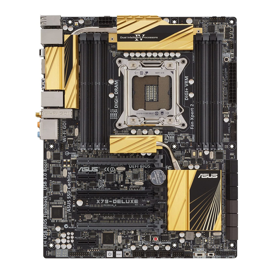
Посмотреть инструкция для Asus X79-DELUXE бесплатно. Руководство относится к категории Материнские платы, 1 человек(а) дали ему среднюю оценку 8.6. Руководство доступно на следующих языках: английский. У вас есть вопрос о Asus X79-DELUXE или вам нужна помощь? Задайте свой вопрос здесь
Не можете найти ответ на свой вопрос в руководстве? Вы можете найти ответ на свой вопрос ниже, в разделе часто задаваемых вопросов о Asus X79-DELUXE.
Какая ширина Asus X79-DELUXE?
Какая толщина Asus X79-DELUXE?
Инструкция Asus X79-DELUXE доступно в русский?
Не нашли свой вопрос? Задайте свой вопрос здесь
(скачивание инструкции бесплатно)
Формат файла: PDF
Доступность: Бесплатно как и все руководства на сайте. Без регистрации и SMS.
Дополнительно: Чтение инструкции онлайн

X79A-GD45
seres
MS-7735 (v1.x) Manboard
G52-77351X3
Europe verson
Страница:
(1 из 178)
навигация

1

2

3

4

5

6

7

8

9

10

11

12

13

14

15

16

17

18

19

20

21

22

23

24

25

26

27

28

29

30

31

32

33

34

35

36

37

38

39

40

41

42

43

44

45

46

47

48

49

50

51

52

53

54

55

56

57

58

59

60

61

62

63

64

65

66

67

68

69

70

71

72

73

74

75

76

77

78

79

80

81

82

83

84

85

86

87

88

89

90

91

92

93

94

95

96

97

98

99

100

101

102

103

104

105

106

107

108

109

110

111

112

113

114

115

116

117

118

119

120

121

122

123

124

125

126

127

128

129

130

131

132

133

134

135

136

137

138

139

140

141

142

143

144

145

146

147

148

149

150

151

152

153

154

155

156

157

158

159

160

161

162

163

164

165

166

167

168

169

170

171

172

173

174

175

176

177

178
Оглавление инструкции
- Страница 1 из 179
X79A-GD45 series MS-7735 (v1.x) Mainboard Europe version G52-77351X3 - Страница 2 из 179
Preface Copyright Notice The material in this document is the intellectual property of MICRO-STAR INTERNATIONAL. We take every care in the preparation of this document, but no guarantee is given as to the correctness of its contents. Our products are under continual improvement and we reserve the - Страница 3 из 179
MS-7735 Technical Support If a problem arises with your system and no solution can be obtained from the user’s manual, please contact your place of purchase or local distributor. Alternatively, please try the following help resources for further guidance. ◙ Contact our technical staff at: - Страница 4 из 179
Preface FCC-B Radio Frequency Interference Statement This equipment has been tested and found to comply with the limits for a Class B digital device, pursuant to Part 15 of the FCC Rules. These limits are designed to provide reasonable protection against harmful interference in a residential - Страница 5 из 179
MS-7735 Battery Information European Union: Batteries, battery packs, and accumulators should not be disposed of as unsorted household waste. Please use the public collection system to return, recycle, or treat them in compliance with the local regulations. For better environmental protection, - Страница 6 из 179
Preface WEEE (Waste Electrical and Electronic Equipment) Statement ENGLISH To protect the global environment and as an environmentalist, MSI must remind you that… Under the European Union (“EU”) Directive on Waste Electrical and Electronic Equipment, Directive 2002/96/EC, which takes effect on - Страница 7 из 179
MS-7735 ESPAÑOL MSI como empresa comprometida con la protección del medio ambiente, recomienda: NEDERLANDS Om het milieu te beschermen, wil MSI u eraan herinneren dat…. De richtlijn van de Europese Unie (EU) met betrekking tot Vervuiling van Electrische en Electronische producten (2002/96/EC), die - Страница 8 из 179
Preface TÜRKÇE Çevreci özelliğiyle bilinen MSI dünyada çevreyi korumak için hatırlatır: Avrupa Birliği (AB) Kararnamesi Elektrik ve Elektronik Malzeme Atığı, 2002/96/EC Kararnamesi altında 13 Ağustos 2005 tarihinden itibaren geçerli olmak üzere, elektrikli ve elektronik malzemeler diğer atıklar - Страница 9 из 179
MS-7735 ▍ Contents Copyright Notice�������������������������������������������������������������������������������������������� ii Trademarks���������������������������������������������������������������������������������������������������� ii Revision - Страница 10 из 179
Preface Tasten������������������������������������������������������������������������������������������������������������� De-25 Steckbrücken�������������������������������������������������������������������������������������������������� De-27 - Страница 11 из 179
English X79A-GD45 Series - Страница 12 из 179
MS-7735 Mainboard Mainboard Specifications Processor Support ■ 2nd Generation Intel® Core™ i7 Processors in an LGA 2011 socket (For the latest information about CPU, please visit http://www.msi.com/service/cpu-support) Chipset ■ Intel® X79 chipset Memory Support ■ 4x DDR3 DIMMs support DDR3 - Страница 13 из 179
Connectors & Buttons English ■ Back panel — 1x PS/2 keyboard/ mouse port — 1x Clear CMOS button — 1x Coaxial S/PDIF-out port — 1x Optical S/PDIF-out port — 1x IEEE 1394 port — 6x USB 2.0 ports — 2x USB 3.0 ports — 1x LAN port — 6x audio ports ■ On-Board — 2x USB 2.0 connectors — 1x USB 3.0 - Страница 14 из 179
MS-7735 Mainboard Connectors Quick Guide DIMM1 DIMM4 CPUFAN1 JPWR2 DIMM2 CPU JCOLD1 DIMM3 SYSFAN2 OC Genie POWER1 Back Direct OC Panel JTURBO1 JPWR1 SYSFAN1 MULTI BIOS SWITCH SYSFAN4 PCI_E1 JCI1 PCI_E2 SATA1/ 2 PCI_E3 SATA3~6 PCI_E4 PCI_E5 JCOLD2 BATT + PCI_E6 PCI_E7 JBAT1 JFP2/JFP1 JAUD1 JTPM1 - Страница 15 из 179
Connectors Reference Guide Port Name Page LGA2011 CPU Socket CPU En-8 ATX 24-pin Power Connector JPWR1 En-13 ATX 8-pin Power Connector JPWR2 En-13 DDR3 Memory Slots DIMM1~4 En-14 PCIe x16 Expansion Slot PCI_E1, 4, 6 En-16 PCIe x1 Expansion Slot PCI_E2, 3, 5, 7 En-16 SATA 6Gb/s Connectors SATA1~2 - Страница 16 из 179
MS-7735 Mainboard Back Panel Quick Guide Mouse/Keyboard Coaxial S/PDIF-Out IEEE 1394 Port LAN Line-In RS-Out Line-Out CS-Out Mic Optical S/PDIF-Out Clear CMOS Button USB 2.0 Port USB 2.0 Port SS-Out USB 3.0 Port ▶ Mouse/Keyboard A combination PS/2® mouse/keyboard DIN connector for a PS/2® - Страница 17 из 179
▶ USB 3.0 Port USB 3.0 port is backward-compatible with USB 2.0 devices. It supports data transfer rate up to 5 Gbit/s (SuperSpeed). Important ▶ LAN The standard RJ-45 LAN jack is for connecting to a Local Area Network (LAN). Yellow Green/ Orange LED Color LED State Condition Left Yellow Off LAN - Страница 18 из 179
MS-7735 Mainboard CPU (Central Processing Unit) Introduction to the LGA2011 CPU The surface of the LGA2011 CPU has four alignment keys and a yellow triangle to assist in correctly lining up the CPU for mainboard placement. The yellow triangle is the Pin 1 indicator. Alignment Key Yellow triangle is - Страница 19 из 179
CPU & Cooler Installation When installing a CPU, always remember to install a CPU cooler. A CPU cooler is necessary to prevent overheating and maintain system stability. Follow the steps below to ensure correct CPU and CPU cooler installation. Wrong installation can damage both the CPU and the - Страница 20 из 179
MS-7735 Mainboard 5. Line up the CPU to fit the CPU socket. Be sure to hold the CPU by the base with the metal contacts facing downward. The alignment keys on the CPU will line up with the edges of the CPU socket to ensure a correct fit. 6. Carefully close the load plate and remove the plastic - Страница 21 из 179
9. Evenly spread a thin layer of thermal paste (or thermal tape) on the top of the CPU. This will help in heat dissipation and prevent CPU overheating. 10. Locate the CPU fan connector on the mainboard. Thermal paste English BATT + CPUFAN1 11. Place the heatsink on the mainboard with the fan’s - Страница 22 из 179
MS-7735 Mainboard Mounting Screw Holes When installing the mainboard, first install the necessary mounting stands required for an mainboard on the mounting plate in your computer case. If there is an I/O back plate that came with the computer case, please replace it with the I/O backplate that came - Страница 23 из 179
Power Supply ATX 24-pin Power Connector: JPWR1 BATT + d n u ro V .G 5 V 4 2 .+ 5 d 3 + V 2 2. +5 s un d 2 1. Re o un d 2 . r 0 G o n # 2 9. Gr rou ON d 1 8. G — un 1 . S 7 P o 1 6. Gr 2V V 1 5. 1 .3 1 4.- +3 1 3. 1 V .3 3 V .+ 2 V 2 1 2 1 1.+ +1 B OK 1 0. VS R nd 1 .5 W u 9 .P ro nd 8 .G 5V u d 7 - Страница 24 из 179
MS-7735 Mainboard Memory These DIMM slots are used for installing memory modules. For more information on compatible components, please visit http://www.msi.com/service/test-report DDR3 240-pin, 1.5V 48×2=96 pin 72×2=144 pin Quad Channel Memory This mainboard supports four memory channels when you - Страница 25 из 179
Installing Memory Modules 1. Unlock the DIMM slot by pushing the mounting clip to the side. Vertically insert the memory module into the DIMM slot. The memory module has an off-center notch on the bottom that will only allow it to fit one way into the DIMM slot. 3. Manually check if the memory - Страница 26 из 179
MS-7735 Mainboard Expansion Slots This mainboard contains numerous ports for expansion cards, such as discrete graphics or audio cards. PCIe (Peripheral Component Interconnect Express) Slot The PCIe slot supports the PCIe interface expansion card. PCIe 3.0 x16 Slot PCIe 2.0 x1 Slot Important When - Страница 27 из 179
Internal Connectors SATA Connector: SATA1~6 This connector is a high-speed SATA interface port. Each connector can connect to one SATA device. SATA devices include disk drives (HDD), solid state drives (SSD), and optical drives (CD/ DVD/ Blu-Ray). BATT + English * The MB layout in this figure is - Страница 28 из 179
MS-7735 Mainboard Fan Power Connectors: CPUFAN1,SYSFAN1~4 The fan power connectors support system cooling fans with +12V. If the mainboard has a System Hardware Monitor chipset on-board, you must use a specially designed fan with a speed sensor to take advantage of the CPU fan control. Remember to - Страница 29 из 179
Front Panel Connectors: JFP1, JFP2 D D in E LE P rL d o e n .N w e d 7 .Po sp n 5 u u .S ro 3 .G 1 JFP2 P o w e r in P o 8. .+ .N 6 .4 + . 2 BATT + 0 e ch w it o w 1 S P r L E D ch it w d e tS rv se ED se e L e R D .R D 9 .+ H 7 .5 .3 .+ 1 JFP1 Important • On the connectors coming from the case, - Страница 30 из 179
MS-7735 Mainboard USB 2.0 Expansion Connectors: JUSB1/ JUSB2 This connector is designed for connecting high-speed USB peripherals such as USB HDDs, digital cameras, MP3 players, printers, modems, and many others. 115V d C un + .N o 1 0 r B 11 .G 8 S B .U S 6 .U C 4 VC . 2 BATT + in P nd o u + .N ro - Страница 31 из 179
USB 3.0 Expansion Connector: JUSB3 The USB 3.0 port is backwards compatible with USB 2.0 devices. It supports data transfer rates up to 5Gbits/s (SuperSpeed). 115V BATT + N D _ DP N r X _ D e R X _ P w _ o B3 _R _C _D .P S 3 d X C 1 .U B n T _ 2 .US rou 3_ TX 3 .G SB 3_ d 4 .U B n 0 5 US rou 2. 0 + - Страница 32 из 179
MS-7735 Mainboard Chassis Intrusion Connector: JCI1 This connector connects to the chassis intrusion switch cable. If the computer case is opened, the chassis intrusion mechanism will be activated. The system will record this intrusion and a warning message will flash on screen. To clear the - Страница 33 из 179
Serial Port Connector: JCOM1 This connector is a 16550A high speed communication port that sends/receives 16 bytes FIFOs. You can attach a serial device. BATT + I S d .R T n 9 . R r ou T 7 .G U 5 . SO C D 3 .D 1 English in P o .N S 0 T R 1 .C S 8 D R . 6 T .D N 4 SI . 2 Voice Genie Connector: - Страница 34 из 179
MS-7735 Mainboard Voltage Check Point Lite These voltage checkpoints are used to measure the current system voltages. A multimeter (not included) will be required to check voltages. To check the voltage, set the voltmeter switch to “DC”, put the positive lead (red) on the postivtive point of the - Страница 35 из 179
Buttons The mainboard has numerous on-board buttons to control various functions. This section will explain how to change your mainboard’s functions through the use of these on-board buttons. BATT + This button is used to automatically overclock the system. Press this button once while the system - Страница 36 из 179
MS-7735 Mainboard Power Button: POWER1 BATT + This button is use to turn-on and turn-off the system. Press the button once to turn-on or turn-off the system. Direct OC Buttons: Plus, Minus These buttons are used to increase or decrease the Base clock frequency. Pressing the Plus/ Minus button once - Страница 37 из 179
Jumpers Clear CMOS Jumper: JBAT1 1 Clear Data BATT + Keep Data 1 Important You can clear the CMOS RAM by shorting this jumper while the system is off. Afterwards, open the jumper . Do not clear the CMOS RAM while the system is on because it will damage the mainboard. Low Temperature Booting Jumper: - Страница 38 из 179
MS-7735 Mainboard Switch Multi BIOS Switch: MULTI BIOS SWITCH BATT + This mainboard has two independent BIOS ROMs (Labeled A and B, default BIOS ROM is A). If one is crashed, you can shift to the other for booting by sliding the switch. In addition, these two BIOS ROMs do not have the Auto Recovery - Страница 39 из 179
LED Status Indicators English CPU_PHASE LEDs DIMM_WARNINGLEDs DrMOS_ALARM LED Debug LED Panel BATT + HDD LED CPU_PHASE LEDs These LEDs will change according to CPU loading. The higher the power phase number, the more reliable the power flow to the processor. DIMM_WARNING LEDs These LEDs will light - Страница 40 из 179
MS-7735 Mainboard Debug LED Panel Please refer to the table below to get more information about the Debug LED message. Post Status 02,07 Power on CPU Initialization 03,08 Power on North Bridge Initialization 04,09 Power on South Bridge Initialization 0B Power on Cache Initialization - Страница 41 из 179
BIOS Setup Click BIOS II is developed by MSI that provides a graphical user interface for setting parameters of BIOS by using the mouse and the keybord. Entering Power on the computer and the system will start POST (Power On Self Test) process. When the message below appears on the screen, press - Страница 42 из 179
MS-7735 Mainboard Important The pictures in this guide are for reference only and may vary from the product you purchased. Please refer to the actual screens of your system for detailed information. ▶ Temperature monitor This block shows the temperature of the processor and the mainboard. ▶ System - Страница 43 из 179
Operation Click BIOS II allows you to control BIOS settings with the mouse and the keyboard. The following table lists and describes the hot keys and the mouse operations. Hot key Mouse <↑↓→← > Description Select Item English Move the cursor Select Icon/ Field <Enter> Click/ Doubleclick the left - Страница 44 из 179
MS-7735 Mainboard OC Menu This menu is for advanced users who want to overclock the mainboard. Important • Overclocking your PC manually is only recommended for advanced users. • Overclocking is not guaranteed, and if done improperly, can void your warranty or severely damage your hardware. • If - Страница 45 из 179
▶ Adjusted CPU Frequency It shows the adjusted CPU frequency. Read-only. ▶ EIST Enhanced Intel SpeedStep technology allows you to set the performance level of the microprocessor whether the computer is running on battery or AC power. This field only appears with installed CPUs that support this - Страница 46 из 179
MS-7735 Mainboard ▶ tRAS Determines the time RAS (row address strobe) takes to read from and write to memory cell. ▶ tRFC This setting determines the time RFC takes to read from and write to a memory cell. ▶ tWR Determines minimum time interval between end of write data burst and the start of a - Страница 47 из 179
▶ tWRDRDD Write-Read Different Ranks same or Different DIMM. ▶ tRWSR Read-Write Same Rank. Important • If you do not have any EMI problem, leave the setting at [Disabled] for optimal system stability and performance. But if you are plagued by EMI, select the value of Spread Spectrum for EMI - Страница 48 из 179
MS-7735 Mainboard ▶ OC Retry Count When overclocking has failed, setting this item to [3,5] will allow system to reboot 3/ 5 times with the same overclocked configuration. If overclocking has failed every time, the system will restore the defaults. ▶ CPU Specifications Press <Enter> to enter the - Страница 49 из 179
▶ Power Technology This item allows you to select the Intel Dynamic Power technology mode. ▶ C1E Support Enable system to reduce CPU power consumption while idle. Not all processors support Enhanced Halt state (C1E). ▶ Intel C-State C-state is a power management state that detects when the system - Страница 50 из 179
MS-7735 Mainboard Updating the BIOS with Live Update This section tells you how to update the BIOS by using the Live Update utility before entering Operating System. Live Update will update the BIOS automatically when connecting to the Internet. To update the BIOS with the Live Update utility: 1. - Страница 51 из 179
Software Information Important Please visit the MSI officially website to get the latest drivers and BIOS for better system performance. Installing Winki BIOS BROWSER and UTILITIES request Winki, please install the «Winki» software application from MSI Driver Disc in Windows first. And then you can - Страница 52 из 179
- Страница 53 из 179
Deutsch X79A-GD45 Serie - Страница 54 из 179
MS-7735 Mainboard Spezifikationen Prozessoren ■ Die 2. Generation der Intel® Core™ i7 Prozessoren für Sockel LGA 2011 (Weitere CPU Informationen finden Sie unter http://www.msi.com/service/cpu-support) Chipsatz ■ Intel® X79 Chipsatz Speicher ■ 4x DDR3 DIMMs unterstützen DDR3 2400*(OC)/ 2133*(OC)/ - Страница 55 из 179
Anschlüsse & Tasten Deutsch ■ Hintere Ein-/ und Ausgänge — PS/2 Tastatur-/Mausanschluss x1 — Clear CMOS Taste x1 — koaxialer S/PDIF-Ausgang x1 — optischer S/PDIF-Ausgang x1 — IEEE 1394 Anschluss x1 — USB 2.0 Anschlüsse x6 — USB 3.0 Anschlüsse x2 — LAN Anschluss x1 — Audiobuchsen x6 ■ On-Board — USB - Страница 56 из 179
MS-7735 Mainboard Anschlussübersicht DIMM1 DIMM4 CPUFAN1 JPWR2 DIMM2 CPU JCOLD1 DIMM3 SYSFAN2 OC Genie POWER1 Rück- Direct OC tafel JTURBO1 JPWR1 SYSFAN1 MULTI BIOS SWITCH SYSFAN4 PCI_E1 JCI1 PCI_E2 SATA1/ 2 PCI_E3 SATA3~6 PCI_E4 PCI_E5 JCOLD2 BATT + PCI_E6 PCI_E7 JBAT1 JFP2/JFP1 JAUD1 JTPM1 - Страница 57 из 179
Übersicht der Mainboard-Anschlüsse Port-Name Seite LGA2011 CPU Sockel CPU De-8 ATX 24-poliger Stromanschluss JPWR1 De-13 ATX 8-poliger Stromanschluss JPWR2 De-13 DDR3 Speichersteckplätze DIMM1~4 De-14 PCIe x16 Erweiterungssteckplatz PCI_E1, 4, 6 De-16 PCIe x1 Erweiterungssteckplatz PCI_E2, 3, 5, 7 - Страница 58 из 179
MS-7735 Mainboard Rücktafel-Übersicht Tastatur/ Maus Koaxialer S/PDIFAusgang IEEE 1394 Anschluss LAN Line-In RS-Out Line-Out CS-Out Mic Optischer USB 2.0 S/PDIF-Ausgang Anschluss CMOS leeren-Taste USB 2.0 Anschluss SS-Out USB 3.0 Anschluss ▶ Maus/Tastatur Die Standard PS/2® Maus/Tastatur Stecker - Страница 59 из 179
▶ USB 3.0 Anschluss Der USB 3.0 Anschluss ist abwärtskompatibel mit USB 2.0-Geräten. Er unterstützt Datentransferraten bis zu 5 Gbit/s (SuperSpeed). Wichtig Um ein USB 3.0 einzusetzen, schließen Sie es bitte mit einem USB 3.0 kompatiblen Kabel an einen USB 3.0 Anschluss an. Gelb Grün/ Orange - Страница 60 из 179
MS-7735 Mainboard CPU (Prozessor) Erklärung zur LGA2011 CPU Die Obserseite der LGA 2011 CPU hat vier Justierungen und ein gelbes Dreieck um die korrekte Ausrichtung der CPU auf dem Motherboard zu gewährleisten. Das gelbe Dreieck des Prozessors definiert die Position des ersten Pins. Justierung Das - Страница 61 из 179
CPU & Kühler Einbau Wenn Sie die CPU einbauen, denken sie bitte daran einen CPU-Kühler zu installieren. Ein CPU-Kühler ist notwendig, um eine Überhitzung zu vermeiden und die Systemstabilität beizubehalten. Befolgen Sie die nachstehenden Schritte, um die richtige CPU und CPU-Kühler Installation zu - Страница 62 из 179
MS-7735 Mainboard 5. Positionieren Sie die CPU so, dass sie auf den Sockel passt. Die CPU muss dabei mit der Pin_seite nach unten zeigen. Vergewissern Sie sich anhand der Justiermarkierungen, dass die CPU in der korrekten Position ist. 6. Verschließen Sie Plastikabdeckung. die Abdeckplatte - Страница 63 из 179
9. Verteilen Sie die dafür geeignete Wärmeleitpaste oder ein Wärmeleitklebepad auf der Oberseite der eingesetzten CPU. Dies verbessert die Wärmeableitung maßgeblich und verhindert damit die Überhitzung des Prozessors. 10. Machen Sie den CPU-Lüfteranschluss auf dem Motherboard ausfindig. - Страница 64 из 179
MS-7735 Mainboard Schraubenlöcher für die Montage Verwenden Sie die dem Mainboard beiliegende I/O-Platte und setzen Sie sie mit leichtem Druck von innen in die Aussparung des Computergehäuses ein. Zur Installation des Mainboards in Ihrem PC-Gehäuse befestigen Sie zunächst die dem Gehäuse - Страница 65 из 179
Stromversorgung ATX 24-poliger Stromanschluss: JPWR1 Mit diesem Anschluss verbinden Sie den ATX 24-poligen Anschluss des Netzteils. Achten Sie bei dem Verbinden des ATX 24-poligen Stromanschlusses darauf, dass der Anschluss des Netzteils richtig auf den Anschluss an der Hauptplatine ausgerichtet - Страница 66 из 179
MS-7735 Mainboard Speicher Diese DIMM-Steckplätze nehmen Arbeitsspeichermodule auf. Die neusten Informationen über kompatible Bauteile finden Sie unter http://www.msi.com/service/test-report DDR3 240-polig, 1,5V 48×2=96 Pole 72×2=144 Pole Quad-Kanal-Speicher Diese Mainboard unterstützt vier - Страница 67 из 179
Vorgehensweise beim Einbau von Speicher Modulen 1. Öffnen Sie den DIMM-Steckplatz, indem Sie die Befestigungsclips zur Seite klappen. Stecken Sie das Speichermodul senkrecht in den DIMM-Steckplatz ein. Das Speichermodul hat eine Kerbe an der Unterseite, so dass es nur in einer Richtung eingesetzt - Страница 68 из 179
MS-7735 Mainboard Erweiterungssteckplätze Dieses Motherboard enthält zahlreiche Schnittstellen für Erweiterungskarten, wie diskrete Grafik-oder Soundkarten. PCIe (Peripheral Component Interconnect Express) Steckplatz Der PCIe Steckplatz unterstützt PCIe-Erweiterungskarten. PCIe 3.0 x16-Steckplatz - Страница 69 из 179
Interne Anschlüsse SATA Anschluss: SATA1~6 Dieser Anschluss basiert auf der Hochgeschwindigkeitsschnittstelle Serial ATA (SATA). Pro Anschluss kann ein Serial ATA Gerät angeschlossen werden. Zu Serial ATA Geräten gehören Festplatten (HDD), SSD Festplatten (SSD) und optische Laufwerke - Страница 70 из 179
MS-7735 Mainboard Stromanschlüsse für Lüfter: CPUFAN1,SYSFAN1~4 Die Anschlüsse unterstützen aktive Systemlüfter mit +12V. Ist Ihr Mainboard mit einem Chipsatz zur Überwachung der Systemhardware versehen, dann brauchen Sie einen speziellen Lüfter mit Geschwindigkeitsregelung, um die Vorteile der - Страница 71 из 179
Frontpanel Anschlüsse: JFP1, JFP2 2 .+ 8 . 6 .+ 4 . Diese Anschlüsse sind für das Frontpanel. Sie dienen zum Anschluss der Schalter und LEDs des Frontpanels. JFP1 erfüllt die Anforderungen des “Intel® Front Panel I/O Connectivity Design Guide”. Bei der Installation des Frontpanel-Anschlüsse, nutzen - Страница 72 из 179
MS-7735 Mainboard USB 2.0 Erweiterungsanschlüsse: JUSB1/ JUSB2 Dieser Anschluss eignet sich für die Verbindung der Hochgeschwindigkeits- USB- Peripheriegeräte, wie z.B. USB Festplattenlaufwerke, Digitalkameras, MP3-Player, Drucker, Modems und ähnliches. 115V d C un + .N o 1 0 r B 11 .G 8 S B .U S 6 - Страница 73 из 179
USB 3.0 Erweiterungsanschluss: JUSB3 Der USB 3.0 Anschluss ist abwärtskompatibel mit USB 2.0-Geräten. Unterstützt Datentransferraten bis 5 Gbit/s (SuperSpeed). 115V N D _ DP in N P r X _ D o e _R X _ P C D .N w 3 R _ _ 0 o B _ 2 .P S B3 nd X _C T 9 1 8.U S ou _ X 1 7.U Gr B3 _T 1 6. S B3 nd 1 .U S - Страница 74 из 179
MS-7735 Mainboard Gehäusekontaktanschluss: JCI1 Dieser Anschluss wird mit einem Kontaktschalter verbunden. Wenn das PC-Gehäuse geöffnet wird, aktiviert dies den Gehäuse-Kontaktschalter und eine Warnmeldung wird auf dem Bildschirm angezeigt. Um die Warnmeldung zu löschen, muss das BIOS aufgerufen - Страница 75 из 179
Serieller Anschluss: JCOM1 Es handelt sich um eine 16550A Kommunikationsschnittstelle, die 16 Bytes FIFOs sendet/empfängt. Hier lässt sich eine serielle Maus oder andere serielle Geräte direkt anschließen. in P o .N S 0 T R 1 .C S 8 D R . 6 T .D N 4 SI . 2 BATT + Deutsch I S d .R T n 9 . R r ou T 7 - Страница 76 из 179
MS-7735 Mainboard Spannungsmesspunkte-Lite Die Spannungsmesspunkte werden verwendet, um die aktuelle Systemspannung zu messen. Ein Multimeter (nicht enthalten) wird für die Spannungsmessung benötigt. Um die Spannung zu prüfen, stellen Sie den Schalter des Spannungsmessers auf “DC”, setzen Sie die - Страница 77 из 179
Tasten Das Motherboard verfügt über zahlreiche On-Board-Tasten, um verschiedene Funktionen zu steuern. Dieser Abschnitt beschreibt, wie man die Funktionen des Motherboards durch den Gebrauch der Taste ändert. OC Genie Taste: OC Genie BATT + Wichtig • Bitte installieren Sie DDR3 1333 oder - Страница 78 из 179
MS-7735 Mainboard Ein-/Ausschalter: POWER1 BATT + Dieser Ein-/ Ausschalter wird verwendet, um das System ein- und auszuschalten. Drücken Sie diese Taste, um das System ein- bzw. auszuschalten. Direct OC Tasten: Plus, Minus Diese Tasten werden benutzt, um die Haupt-Taktfrequenz zu erhöhen oder zu - Страница 79 из 179
Steckbrücken Steckbrücke zur CMOS-Löschung: JBAT1 Der Onboard CMOS Speicher (RAM) wird durch eine externe Spannungsversorgung durch eine Batterie auf dem Mainboard versorgt, um die Daten der Systemkonfiguration zu speichern. Er ermöglicht es dem Betriebssystem, mit jedem Einschalten automatisch - Страница 80 из 179
MS-7735 Mainboard Schalter Multi BIOS Schalter: MULTI BIOS SWITCH BATT + Das Mainboard besitzt zwei unabhängige BIOS ROM’s (bezeichnet als A und B, Standard ist BIOS ROM A). Falls ein BIOS abgestürzt ist, können Sie durch verschieben des Schalters zum zweiten BIOS umschalten um zu starten. Die - Страница 81 из 179
LED Statusanzeige CPU_PHASE LEDs Deutsch DIMM_WARNINGLEDs DrMOS_ALARM LED Debug LED Panel BATT + HDD LED CPU_PHASE LEDs Diese LEDs leuchten abhängig von der CPU-Last. Je höher die Phasenanzahl, desto höher ist der Stromzufluss zum Prozessor. DIMM_WARNING LEDs Diese LEDs leuchten, wenn die in DIMM 2 - Страница 82 из 179
MS-7735 Mainboard Debug-LED-Panel Weitere Informationen zu den Debug-LED-Meldungen entnehmen Sie bitte der nachstehenden Tabelle. Post Status 02,07 CPU-Initialisierung 03,08 Northbridge-Initialisierung 04,09 Southbridge-Initialisierung 0B Cache-Initialisierung 11~14,32~36,56~5A Frühe - Страница 83 из 179
BIOS Setup CLICK BIOS II wird von MSI entwickelt, die eine grafische Benutzeroberfläche der BIOS-Einstellparameter mit Maus und Tastatur bietet. Mit CLICK BIOS II können Benutzer die BIOS-Einstellungen ändern, die CPU-Temperatur überwachen, die Boot-reihenfolge festlegen und die Systeminformationen - Страница 84 из 179
MS-7735 Mainboard Überbilck Nach dem Aufrufen der Click BIOS II, ist das eine der folgenden Anzeigen. Temperaturüberwachung Auswahl des Modus SystemInformation Boot-Menü Bootgerät Prioritätleiste BIOS-MenüAuswahl BIOS-MenüAuswahl Menüanzeige Wichtig Die Bilder in diesem Handbuch sind nur zur - Страница 85 из 179
■ Boot-Geräte Prioritätsleiste Die Leiste zeigt die Reihenfolge der Boot-Geräte. Die Symbole zeigen die verfügbaren Geräte. Hohe Priorität Niedrigere Priorität Klicken Sie und ziehen Sie das Symbol nach links oder rechts, um die Boot-Priorität festzulegen. Betrieb CLICK BIOS II ermöglicht Ihnen, - Страница 86 из 179
MS-7735 Mainboard <Esc> Aufruf Exit Menü oder zurück zum Hauptmenü von Untermenü Klicken Sie mit der rechten Maustaste <+> Hochzählen oder ändern eines Wertes <-> Herunterzählen oder ändern eines Wertes <F1> Allgemeine Hilfe <F4> CPU-Spezifikationen <F5> Aufruf des Memory-Z Fensters mit Details zum - Страница 87 из 179
OC-Menü In diesem Menü können Benutzer das BIOS anpassen und übertakten. Bitte führen Sie nur Änderungen durch, wenn Sie sich über das Ergebniss sicher sind. Sie sollten Erfahrung beim Übertakten haben, da Sie sonst das Mainboard oder Komponenten des Systems beschädigen können. Deutsch Wichtig • - Страница 88 из 179
MS-7735 Mainboard Dieser Eintrag ist nur verfügbar, wenn der Prozessor diese Funktion unterstützt (freier Multiplikator). ▶ Adjusted CPU Frequency Es zeigt die eingestellten Frequenz der CPU. Nur Anzeige – keine Änderung möglich. ▶ EIST Die weiterentwickelte Intel SpeedStep Technologie erlaubt - Страница 89 из 179
dress Strobe — RAS) für eine Vorbereitung bekommt. Wird dem RAS bis zur Auffrischung des DRAM nicht genug Zeit zum Aufbau seiner Ladung gegeben, kann der Refresh unvollständig ausfallen und das DRAM Daten verlieren. Dieser Menüpunkt ist nur relevant, wenn synchroner DRAM verwendet wird. ▶ tRAS - Страница 90 из 179
MS-7735 Mainboard ▶ tWWDD Schreib-Schreib Verschiedene Reihe. ▶ tRWDRDD Lese-Schreib Verschiedene Reihe, gleiche oder Verschiedene DIMM. ▶ tWRDRDD Schreib-Lese Verschiedene Reihe, gleiche oder Verschiedene DIMM. ▶ tRWSR Lese-Schreib gleiche Reihe. ▶ Spread Spectrum Die Spread Spectrum Funktion - Страница 91 из 179
▶ Load/ Clear Overclocking Profile 1/ 2/ 3/ 4/ 5/ 6 Laden/ Löschen der gespeicherten Profileinstellungen von ROM. ▶ Overclocking Profile Save Speichern Sie die aktuelle Übertaktungs-Einstellungen auf USB-Flashspeicher. ▶ Overclocking Profile Load Laden Sie die gespeicherten Einstellungen von - Страница 92 из 179
MS-7735 Mainboard ▶ Execute Disable Bit Es kann an den Rechner gerichtete “Buffer Overflow” Angriffe verhindern, bei denen Würmer, um Ihr System mit Codeausführung zu beschädigen. Es wird empfohlen, halten Sie diese stets aktiviert. ▶ Intel Virtualization Tech Enhances virtualization and allows the - Страница 93 из 179
Aktualisierung BIOS mit dem Live-Update Dieser Abschnitt erklärt, wie Sie das BIOS mit Hilfe des Live-Update-Programms aktualisieren können, noch das Betriebssystem gestartet wurde. Bei einer bestehenden Internetverbindung kann Live-Update das BIOS selbstständig aktualisieren. Um das BIOS mit dem - Страница 94 из 179
MS-7735 Mainboard Software-Information Die im Mainboard-Paket enthaltene Disc enthält alle notwendigen Treiber. Um die Installation automatisch laufen zu lassen, klicken Sie einfach den Treiber oder Utiltiy und folgen Sie dem Pop-Up Schirm, um die Installation durchzuführen. Der - Страница 95 из 179
Français X79A-GD45 Séries - Страница 96 из 179
Carte mère MS-7735 Spécifications Processeurs Supportés ■ 2ème Génération Intel® Core™ i7 Processeurs dans le socket LGA 2011 (Pour plus d’information sur le CPU, veuillez visiter http://www.msi.com/service/cpu-support) Jeu de puces ■ Puces Intel® X79 Mémoire supportée ■ 4x DDR3 DIMMs supportent - Страница 97 из 179
Connecteurs & Boutons Français ■ Panneau arrière — 1x port clavier/ souris PS/2 — 1x bouton d’effacement CMOS — 1x port S/PDIF-out coaxial — 1x port S/PDIF-out optique — 1x port IEEE 1394 — 6x ports USB 2.0 — 2x ports USB 3.0 — 1x port LAN — 6x ports audio ■ Connecteurs intégrés — 2x connecteurs - Страница 98 из 179
Carte mère MS-7735 Guide Rapide Des Connecteurs DIMM1 DIMM4 CPUFAN1 JPWR2 DIMM2 CPU JCOLD1 DIMM3 SYSFAN2 OC Genie POWER1 Panneau arrière Direct OC JTURBO1 JPWR1 SYSFAN1 MULTI BIOS SWITCH SYSFAN4 PCI_E1 JCI1 PCI_E2 SATA1/ 2 PCI_E3 SATA3~6 PCI_E4 PCI_E5 JCOLD2 BATT + PCI_E6 PCI_E7 JBAT1 JFP2/JFP1 - Страница 99 из 179
Guide référence des connecteurs Noms de ports Page LGA2011 CPU Socket CPU Fr-8 Connecteur d’alimentation ATX 24-pin JPWR1 Fr-13 Connecteur d’alimentation ATX 8-pin JPWR2 Fr-13 Emplacements de mémoire DDR3 DIMM1~4 Fr-14 Emplacement d’extension PCIe x16 PCI_E1, 4, 6 Fr-16 Emplacement d’extension PCIe - Страница 100 из 179
Carte mère MS-7735 Guide rapide du panneau arrière Souris/Clavier S/PDIF-Out coaxial Port IEEE 1394 LAN Ligne-In RS-Out Ligne-Out CS-Out Mic S/PDIF-Out optique Bouton d’effacement CMOS Port USB 2.0 Port USB 2.0 SS-Out Port USB 3.0 ▶ Souris/Clavier Connecteur souris/ clavier DIN de PS/2® pour une - Страница 101 из 179
▶ Port USB 3.0 Le port USB 3.0 est rétro-compatible avec les périphériques USB 2.0. Il supporte le taux de transfert jusqu’à 5 Gbit/s (Super-Vitesse). Important Si vous voulez installer un périphérique USB 3.0, il faut utiliser une câble USB 3.0 pour connecter au port USB 3.0. ▶ LAN La prise - Страница 102 из 179
Carte mère MS-7735 Processeur : CPU Introduction du LGA2011 CPU A la surface du CPU LGA2011, vous noterez quatre clés d’alignement et un triangle jaune servant à aligner le CPU dans la bonne position sur la carte mère. Le triangle jaune corresponde à la Pin 1. Clé d’alignement Le triangle jaune - Страница 103 из 179
Installation du CPU et son ventilateur Quand vous installez le CPU, assurez-vous que le CPU soit équipé d’un ventilateur, qui est nécessaire pour éviter la surchauffe et maintenir la stabilité. Suivez les instruction suivantes pour installer le CPU et son ventilateur correctement. Une installation - Страница 104 из 179
Carte mère MS-7735 5. Alignez le CPU sur le socket CPU. Assurez-vous de tenir le CPU par le base avec les contacts métaux vers le bas. La clé d’alignement du CPU s’aligne sur les bords du socket CPU pour garantir une bonne correspondance. 6. Fermez la plaque de charge et enlevez le couvercle - Страница 105 из 179
9. Etendez uniformément une fine couche de pâte thermique (ou bande thermique sur le haut du CPU. Cela peut aider la dissipation de chaleur et prévenir le surchauffe du CPU. 10. Localisez le connecteur du ventilateur de CPU sur la carte mère. Pâte thermique BATT + CPUFAN1 12. Servez-vous d’un - Страница 106 из 179
Carte mère MS-7735 Trous Taraudés de Montage Avant d’installer votre carte mère, il faut d’abord installer les socles de montage néce saires sur le plateau de montage du boîtier de l’ordinateur. Si la boîtier de l’ordinateur est accompagnée par un panneau Entrée/ Sortie arrière, veuillez utiliser - Страница 107 из 179
Connecteurs d’alimentation Connecteur d’alimentation ATX 24-pin : JPWR1 Ce connecteur vous permet de relier une alimentation ATX 24-pin. Pour cela, alignez le câble d’alimentation avec le connecteur et appuyez fermement le câble dans le connecteur. Si ceci est bien fait, la pince sur le câble - Страница 108 из 179
Carte mère MS-7735 Mémoire Ces emplacements DIMM sont destinés à installer les modules de mémoire. Pour plus d’informations sur les composants compatibles, veuillez visiter http://www.msi.com/service/test-report DDR3 240-pin, 1.5V 48×2=96 pin 72×2=144 pin Mémoire à Quatre-Canal Cette carte mère - Страница 109 из 179
Installation des modules de mémoire 1. Déverouillez l’emplacement DIMM en repoussant les pinces de montage sur le côté. Insérez verticalement le module de mémoire dans l’emplacement DIMM. Le module de mémoire possède une seule encoche en son centre sur le bas et ne s’adaptera que s’il est orienté - Страница 110 из 179
Carte mère MS-7735 Emplacements d’extension Cette carte mère contient de nombreux ports pour les cartes d’extension, tels que les cartes graphiques ou les cartes audio. Emplacement PCIe (Peripheral Component Interconnect Express) L’emplacement PCIe supporte la carte d’extension d’Interface PCIe. - Страница 111 из 179
Connecteurs internes Connecteur SATA : SATA1~6 * Le schéma de carte mère dans la figure n’est qu’à titre de référence. SATA6 SATA5 SATA4 SATA3 SATA2 SATA1 SATA1~2 (6Gb/s, par Intel® X79) SATA3~6 (3Gb/s, par Intel® X79) Important • De nombreux périphériques SATA ont besoin d’un câble d’alimentation. - Страница 112 из 179
Carte mère MS-7735 Connecteur d’alimentation du ventilateur : CPUFAN1,SYSFAN1~4 Les connecteurs d’alimentaion du ventilateur supportent les ventilateurs de type +12V. Si la carte mère est équipée d’un moniteur du matériel de système intégré, vous devrez utiliser un ventilateur spécial pourvu d’un - Страница 113 из 179
Connecteur panneau avant : JFP1, JFP2 2 .+ 8 . 6 .+ 4 . Ces connecteurs se connectent aux interrupteurs et LEDs du panneau avant. Le JFP1 est conforme au guide de conception de la connectivité Entrée/sortie du panneau avant Intel®. Lors d’installation des connecteurs du panneau avant, veuillez - Страница 114 из 179
Carte mère MS-7735 Connecteurs d’extension USB 2.0 : JUSB1/ JUSB2 Ce connecteur est destiné à connecter les périphériques USB de haute-vitesse tels que lecteurs de disques durs (HDDs) USB, les appareils photo numériques, les lecteurs MP3, les imprimantes, les modems et les appareils similaires. - Страница 115 из 179
Connecteurs d’extension USB 3.0 : JUSB3 Le port USB 3.0 est rétro-compatible avec les périphériques USB 2.0. Il supporte un taux de transfert jusqu’à 5 Gbit/s (Super-Vitesse). 115V N D _ DP in N P r X _ D o e _R X _ P C D .N w 3 R _ _ 0 o B _ 2 .P S B3 nd X _C T 9 1 8.U S ou _ X 1 7.U Gr B3 _T 1 6. - Страница 116 из 179
Carte mère MS-7735 Connecteur Châssis Intrusion : JCI1 Ce connecteur permet de connecté un câble de détecteur d’ouverture du boîtier. Lorsque le boîtier est ouvert, le détecteur en informera le système, qui affichera un message d’alerte. Pour effacer ce message d’alerte, vous devez entrer dans le - Страница 117 из 179
Connecteur de port série : JCOM1 Le port serie est un port de communications haute vitesse 16550A, qui envoie/ reçoit 16 bytes FIFOs. Vous pouvez y relier un périphérique série. in P o .N S 0 T R 1 .C S 8 D R . 6 T .D N 4 SI . 2 BATT + I S d .R T n 9 . R r ou T 7 .G U 5 . SO C D 3 .D 1 Ce - Страница 118 из 179
Carte mère MS-7735 Point vérification de tension Ces points vérification de tension servent à mesurer les tensions actuelles du système. Il faut un multimètre (non compris) pour vérifier les tensions. Afin de mesurer la tension, réglez l’interrupteur de voltmètre en «DC» (courant continue), mettez - Страница 119 из 179
Boutons Cette carte mère possède de nombreux boutons pour contrôler les fonctions variées. Cette section vous explique comment changer la fonction de votre carte mère avec ces boutons intégrés. Bouton OC Genie : OC Genie Ce bouton sert à auto-overclocker le système. Appuyez ce bouton une fois - Страница 120 из 179
Carte mère MS-7735 Bouton d’alimentation : POWER1 BATT + Ce bouton sert à allumer ou éteindre le système. Appuyez ce bouton pour allumer ou éteindre le système. Boutons OC directs : Plus, Moins Ces boutons servent à augmenter ou diminuer la fréquence d’horloge de base. Appuyez sur le bouton Plus/ - Страница 121 из 179
Cavaliers Cavalier d’effacement CMOS : JBAT1 Il y a un CMOS RAM intégré, qui possède un bloc d’alimentation alimenté par une batterie externe, destiné à conserver les données de configuration du système. Avec le CMOS RAM, le système peut lancer automatiquement le système d’exploitation chaque fois - Страница 122 из 179
Carte mère MS-7735 Interrupteur Interrupteur Multi BIOS : MULTI BIOS SWITCH BATT + La carte mère est équipée de deux BIOS ROMs (étiquetés A et B, celui par défaut est A). Si un des deux est cassé, vous pouvez régler à l’autre pour démarrage par le glissement de l’interrupteur. En plus, ces deux - Страница 123 из 179
Indicateurs de Statut LED CPU_PHASE LEDs DIMM_WARNINGLEDs Français DrMOS_ALARM LED Debug LED Panel BATT + HDD LED CPU_PHASE LEDs Ces LEDs changent selon le chargement du CPU. Plus haut est le nombre de phase d’alimentation, plus fiable est l’alimentation vers le processeur. DIMM_WARNING LEDs Ces - Страница 124 из 179
Carte mère MS-7735 Debug LED Panneau Veuillez vous référer au tableau suivant pour plus d’information sur le message Debug LED. Poste Etat 02,07 Allumer l’initialisation du CPU 03,08 Allumer l’initialisation North Bridge 04,09 Allumer l’initialisation South Bridge 0B Allumer l’initialisation Cache - Страница 125 из 179
Réglage BIOS Click BIOS II est développé par MSI qui fournit une interface graphique d’utilisateur pour régler les paramètres de BIOS a l’aide de la souris et le clavier. Avec Click BIOS II, vous pouvez modifier les réglages BIOS, surveiller la température du CPU, choisir la priorité de - Страница 126 из 179
Carte mère MS-7735 Important Les photos dans cette guide ne sont qu’à titre de référence et peuvent varier selon le modèle que vous achetez. Veuillez vous référer à l’écran actuel de votre système pour les informations détaillées. ▶ Surveiller la température Cette partie montre la température du - Страница 127 из 179
Opération CLICK BIOS II vous permet de contrôler les réglages BIOS avec la souris et le clavier. La liste ci-dessous décrit les opérations des touches raccourcis et de la souris. Clavier Souris <↑↓→← > Description Choisir un article Bouger le curseur Choisir une icône/ un domaine <Enter> Cliquer/ - Страница 128 из 179
Carte mère MS-7735 OC Menu Ce menu est destiné aux utilisateur avancés souhaitant overclocker la carte mère. Important • L’Overclocking manuel du PC n’est recommandé que pour les utilisateurs avancés. • L’Overclocking n’est pas garanti, et une mauvaise manipulation peut invalider votre garantie et - Страница 129 из 179
▶ Adjusted CPU Frequency Il montre la fréquence ajustée du CPU . Lecture uniquement. ▶ EIST L’Enhanced Intel SpeedStep Technologie vous permet de configurer le niveau de performance du microprocesseur si l’ordinateur fonctionne sur batterie ou sur secteur. Ce menu apparaîtra si vous installez un - Страница 130 из 179
Carte mère MS-7735 ▶ tRAS L’article détermine le temps que le RAS prend pour lire ou écrire une cellule de mémoire. ▶ tRFC Cette fonction permet de déterminer le temps que le RFC prend pour lire ou écrire une cellule demémoire. ▶ tWR L’intervalle de temps minimum entre la fin d’apparition - Страница 131 из 179
▶ tRWDRDD Lecture-Ecriture Différent cadres pareils ou Différent DIMM. ▶ tWRDRDD Ecriture-Lecture Différent Cadres pareils ou Différent DIMM. ▶ tRWSR Lecture-Ecriture même Cadre. ▶ Spread Spectrum Cette fonction réduit l’EMI (Interférences Electromagnétique) causé par la modulation de fréquence de - Страница 132 из 179
Carte mère MS-7735 ▶ Overclocking Profile Load Charger un profil d’overclocking depuis un disque flash USB. ▶ OC Retry Count A l’échec de l’overclocking, la mise en [1, 3] de cet article permet au système de redémarrer 1/ 3 fois avec la même configuration overclockée. Si l’overclocking échoue - Страница 133 из 179
▶ Intel Virtualization Tech Il améliore la virtualisation et permet au système de fonctionner comme de multiples système virtuels. Référez-vous au site officiel pour plus d’information. ▶ Intel VT-D Tech Cet fonction sert à activer/ désactiver la technologie Intel VT-D. Pour plus d’information - Страница 134 из 179
Carte mère MS-7735 Mettre à jour le BIOS avec Live Update Cette partie vous explique comment mettre à jour le BIOS en utilisant l’utilitaire Live Update avant d’entrer dans le système d’exploitation. Live Update mettra à jour le BIOS automatiquement lorsqu’il est connecté à l’Internet. Pour mettre - Страница 135 из 179
Information Logiciel Sortez le Disc ‘Pilote/Service’, qui est inclus dans la boîte de la carte mère et placez-le dans le lecteur optique. L’installation va automatiquement se déclencher, cliquez sur le pilote ou sur l’utilitaire et suivez les instructions à l’écran pour l’installation. Le Disc - Страница 136 из 179
- Страница 137 из 179
Русский X79A-GD45 Серия - Страница 138 из 179
MS-7735 Системная плата Характеристики системной платы Поддержка процессоров ■ Процессоры Intel® Core™ i7 2-ой генерации для разьема LGA 2011 (Список поддерживаемых процессоров можно найти на сайте http://www.msi.com/service/cpu-support) Чипсет ■ Intel® X79 Память ■ 4x слота DDR3 DIMM с поддержкой - Страница 139 из 179
Разъемы и кнопки Русский ■ Разъемы на задней панели — 1x PS/2 порт клавиатуры/мыши — 1x кнопка Clear CMOS — 1x коаксиальный выход S/PDIF-out — 1x оптический выход S/PDIF-out — 1x порт IEEE 1394 — 6x портов USB 2.0 — 2x порта USB 3.0 — 1x порт LAN — 6x аудиоразъемов ■ Разъемы на плате — 2x разъема - Страница 140 из 179
MS-7735 Системная плата Краткое руководство по разъемам DIMM1 DIMM4 CPUFAN1 JPWR2 DIMM2 CPU JCOLD1 DIMM3 SYSFAN2 OC Genie POWER1 Разъемы на задней панели Direct OC JTURBO1 JPWR1 SYSFAN1 MULTI BIOS SWITCH SYSFAN4 PCI_E1 JCI1 PCI_E2 SATA1/ 2 PCI_E3 SATA3~6 PCI_E4 PCI_E5 JCOLD2 BATT + PCI_E6 PCI_E7 - Страница 141 из 179
Справочное руководство по разъемам Тип разъема Идентификационное Номер имя разъема страницы Разъем для процессора LGA2011 CPU Ru-8 24-контактный разъем питания ATX JPWR1 Ru-13 8-контактный разъем питания ATX JPWR2 Ru-13 Разъемы для модуля памяти DDR3 DIMM1~4 Ru-14 Слот расширения PCIe x16 PCI_E1, - Страница 142 из 179
MS-7735 Системная плата Разъемы на задней панели Мышь/ клавиатура Коаксиальный S/PDIF-Out Порт IEEE 1394 Сеть Линейный RS-выход вход Линейный CS-выход выход Микрофон SS-выход Оптический S/PDIF-Out Кнопка очистки CMOS Порт USB 2.0 Порт USB 2.0 Порт USB 3.0 ▶ Разъем мыши/клавиатуры Комбинированный - Страница 143 из 179
▶ Порт USB 3.0 Порт USB 3.0 обратно совместим с устройствами USB 2.0. Поддержка передачи данных со скоростью до 5 Гбит/с (SuperSpeed). Внимание! Для использования устройств USB 3.0 их следует подключать к порту USB 3.0. Используемый USB-кабель должен быть совместим со стандартом USB 3.0. ▶ Сеть - Страница 144 из 179
MS-7735 Системная плата CPU (Центральный процессор) Процессор форм-фактора LGA2011 На поверхности CPU LGA2011 имеются два ключа совмещения и желтый треугольник, помогающие правильно разместить CPU на материнской плате. Желтый треугольник указывает Контакт 1. Ключ совмещения Желтый треугольник - Страница 145 из 179
Установка CPU и вентилятора При установке CPU убедитесь, что на нем установлен вентилятор, предотвращающий перегрев процессора. При установке радиатора/вентилятора не забудьте нанести на CPU термопасту, улучшающую теплопередачу. Для правильной установки вентилятора и процессора выполните следующие - Страница 146 из 179
MS-7735 Системная плата 5. После проверки правильности ориентации процессора относительно сокета, установите его в разъем. Держать процессор рекомендуется только за края его основания. Проверьте правильность расположения ключей совмещения. 6. Аккуратно снимите пластиковую заглушку и опустите - Страница 147 из 179
9. Нанесите тонкий ровный слой термопасты (или термоленту) на верхнюю часть CPU. Это улучшит теплоотвод и предотвратит перегрев CPU. 10. Найдите разъем (CPUFAN1). питания вентилятора CPU на материнской плате Термопаста BATT + CPUFAN1 11. Разместите радиатор системы охлаждения на системной плате - Страница 148 из 179
MS-7735 Системная плата Отверстия под установочные винты При установке материнской платы сначала установите необходимые для материнской платы ножки на шасси в системном блоке. Если к системному блоку прилагается задняя панель портов ввода/вывода, замените ее панелью, входящей в комплект материнской - Страница 149 из 179
Электропитание 24-контактный разъем питания ATX: JPWR1 Этот разъем позволяет подключить 24-контактный разъем питания ATX. Перед подключением источника питания убедитесь, что его контакты и разъем на плате правильно сориентированы. Затем плотно вставьте его в разъем на системной плате. При - Страница 150 из 179
MS-7735 Системная плата Память Слоты DIMM используются для установки модулей памяти. Подробную информацию о совместимых компонентах см. на сайте http://www.msi.com/service/test-report DDR3 240-контактов, 1.5V 48×2=96 контактов 72×2=144 контакта Четверо-канальная память Эта системная плата - Страница 151 из 179
Установка модулей памяти 1. Разблокируйте DIMM слот, разведя зажимы в стороны. Вставьте модуль памяти в слот DIMM вертикально. На модуле памяти имеется смещенная от центра выемка внизу, благодаря которой его можно вставить в гнездо DIMM только определенным образом. 2. Вставьте модуль памяти в слот - Страница 152 из 179
MS-7735 Системная плата Слоты расширения Данная материнская плата содержит несколько слотов для плат расширения, таких как дискретные видео и аудио карты. Слот PCIe (Peripheral Component Interconnect Express) Слот PCIe поддерживает карты расширения интерфейса PCIe. PCIe 3.0 x16 Слот PCIe 2.0 x1 - Страница 153 из 179
Разъемы Разъем SATA: SATA1~6 BATT + Данный разъем является высокоскоростным интерфейсом SATA. К любому разъему SATA можно подключить одно устройство SATA. К устройствам SATA относятся дисководы (HDD), твердотельные накопители (SSD) и оптические диски (CD/ DVD/ Blu-Ray). SATA6 SATA5 SATA4 SATA3 - Страница 154 из 179
MS-7735 Системная плата Разъемы питания вентиляторов: CPUFAN1,SYSFAN1~4 В разъемы питания для вентиляторов разрешается установка вентиляторов с питанием +12 В. Если на системной плате имеется чипсет Монитора системного оборудования, вы должны использовать специально разработанный вентилятор с - Страница 155 из 179
Разъемы передней панели: JFP1, JFP2 2 .+ 8 . 6 .+ 4 . Эти разъемы используются для подключения кнопок и светодиодных индикаторов, расположенных на передней панели системного блока. Разъем JFP1 соответствует стандарту Intel® Front Panel I/O Connectivity Design. Для упрощения процедуры подключения - Страница 156 из 179
MS-7735 Системная плата Выносные порты USB 2.0: JUSB1/ JUSB2 Разъем, соответствующий стандартам Intel® I/O Connectivity Design, идеально подходит для подключения высокоскоростных устройств USB, например жестких дисков USB, цифровых камер, МРЗ плееров, принтеров, модемов и т. д. 115V d C un + .N o 1 - Страница 157 из 179
Выносные порты USB 3.0: JUSB3 Порт USB 3.0 обратно совместим с устройствами USB 2.0. Поддержка передачи данных со скоростью до 5 Гбит/с (SuperSpeed). 115V N D _ DP in N P r X _ D o e _R X _ P C D .N w 3 R _ _ 0 o B _ 2 .P S B3 nd X _C T 9 1 8.U S ou _ X 1 7.U Gr B3 _T 1 6. S B3 nd 1 .U S u .0 + o 5 - Страница 158 из 179
MS-7735 Системная плата Разъем датчика открывания корпуса: JCI1 К этому разъему подключается кабель датчика, установленного в корпусе. Датчик вскрытия корпуса срабатывает при вскрытии системного блока. Система регистрирует вскрытие и выводит на экран предупреждение. Для отключения предупреждения - Страница 159 из 179
Разъем последовательного порта: JCOM1 Данный разъем является высокоскоростным последовательным портом передачи данных 16550А с 16-разрядной передачей FIFO. К этому разъему можно подключить устройство c последовательным интерфейсом. in P o .N S 0 T R 1 .C S 8 D R . 6 T .D N 4 SI . 2 BATT + I S d .R - Страница 160 из 179
MS-7735 Системная плата Разъемы для замера напряжения Voltage Check Point Lite Данные контрольные точки используются для измерения текущего напряжения системы. Для проверки напряжения необходим мультиметр (приобретается отдельно). Для проверки напряжения, установите переключатель вольтметра в “DC”, - Страница 161 из 179
Кнопки На материнской плате имеется ряд кнопок для управления различными функциями. Эта глава поясняет возможности каждой из кнопок. Кнопка OC Genie: OC Genie Эта кнопка используется для автоматического разгона системы. Нажмите эту кнопку для включения функции OC Genie, когда система выключена. - Страница 162 из 179
MS-7735 Системная плата Кнопка питания: POWER1 BATT + Эта кнопка предназначена для включения и выключения системы. Нажмите на кнопку для включения или выключения системы. Кнопки Direct OC: Плюс, Минус Эти кнопки используются для изменения основной тактовой частоты. Нажатие кнопки Плюс/ Минус один - Страница 163 из 179
Перемычки Перемычка очистки данных CMOS: JBAT1 На плате установлена CMOS память с питанием от батарейки, хранящая данные о конфигурации системы. С помощью памяти CMOS, система автоматическизагружается каждый раз при включении. Если у вас возникает необходимость сбросить конфигурацию системы - Страница 164 из 179
MS-7735 Системная плата Переключатель Переключатель Multi BIOS: MULTI BIOS SWITCH BATT + В этой плате имеются два независимых BIOS ROM (С этикеткой A и B, BIOS ROM по умолчанию — с этикеткой A). Если один поврежден, вы можете скольжением переключателем сдвигать в другой для загрузки. Кроме того, - Страница 165 из 179
Световые индикаторы CPU_PHASE LEDs DIMM_WARNINGLEDs DrMOS_ALARM LED Русский Debug LED Panel BATT + HDD LED Индикаторы фаз CPU (CPU_PHASE LEDs) Эти индикаторы реагируют на уровень загрузки CPU. Больше количество фаз делает питание процессора более стабильным. Индикаторы DIMM_WARNING (DIMM_WARNING - Страница 166 из 179
MS-7735 Системная плата Панель индикаторов загрузки (Debug LED Panel) Коды индикатора загрузки (Debug LED) перечислены в таблице ниже. Код Состояние 02,07 Питание включено — инициализация CPU 03,08 Питание включено — инициализация Северного моста 04,09 Питание включено — инициализация Южного моста - Страница 167 из 179
Настройка BIOS Технология Click BIOS II проектированна компанией MSI, предлагающая Графический пользовательский интерфейс для установки параметров BIOS мышью и клавиатурой. С помощью the Click BIOS II, пользователь может изменять настройки BIOS, отслеживать температуру CPU, определять - Страница 168 из 179
MS-7735 Системная плата Общие Сведения После входа в Click BIOS II отображается следующий экран. Мониторинг Температур Выбор режима Выбор раздела BIOS Системная информация Меню Загрузки Приоритет загрузочных устройств Выбор раздела BIOS Экран просмотра раздела Внимание! Изображения в данном - Страница 169 из 179
■ SECURITY (БЕЗОПАСНОСТЬ) – меню безопасности используется для защиты системы и предотвращения изменения настроек системы неавторизованным пользователем. ▶ Приоритет загрузочных устройств Вы можете изменять приорит загрузки устройств, путем перемещения пиктограмм. ▶ Меню Загрузки Эта кнопка - Страница 170 из 179
MS-7735 Системная плата <Esc> Переход в меню Exit (Выход) или возврат к предыдущему меню из подменю Щелчок правой кнопкой <+> Увеличение или изменение значения параметра. <-> Уменьшение или изменение значения параметра. <F1> Общая справка <F4> Спецификация CPU <F5> Вход в Memory-Z <F6> Установка - Страница 171 из 179
Меню OC Данное меню предназначено для опытных пользователей и предоставляет возможности для “Overclocking (разгона)” системы. • Разгонять ПК вручную рекомендуется только опытным пользователям. • Производитель не гарантирует успешность разгона. Неправильное выполнение разгона может привести к - Страница 172 из 179
MS-7735 Системная плата ▶ Adjusted CPU Frequency Этот пункт показывает текущую частоту CPU. Только для чтения. ▶ EIST Технология Enhanced Intel SpeedStep позволяет установить уровень производительности процессора при электропитании от батареи или от сети. Данное поле появляется только в случае - Страница 173 из 179
▶ tRAS Определяет время, требуемое RAS (стробу адреса строки) для считывания из ячейки памяти или записи в нее. ▶ tRFC Этот пункт определяет время, которое RFC затрачивает на чтение и запись в ячейку памяти. ▶ tWR Определяет минимальную временную задержку между выполнением операции записи и - Страница 174 из 179
MS-7735 Системная плата ▶ tWWDR Write-Write Different Rank, same DIMM (Писать задержки разного ранга в одном и том же DIMM). ▶ tWWDD Write-Write Different Rank (Писать задержки разного ранга). ▶ tRWDRDD Read-Write Different Ranks same or Different DIMM (Читать-писать задержки разного ранга в одном - Страница 175 из 179
▶ Set Name for Overclocking Profile 1/ 2/ 3/ 4/ 5/ 6 Укажите имя в этом поле. ▶ Save Overclocking Profile 1/ 2/ 3/ 4/ 5/ 6 Сохраните текущие настройки разгона для выбранного профиля на ПЗУ. ▶ Load/ Clear Overclocking Profile 1/ 2/ 3/ 4/ 5/ 6 Сохранение/удаление настроек профиля разгона на ПЗУ. ▶ - Страница 176 из 179
MS-7735 Системная плата ▶ Execute Disable Bit Может предотвратить определенные виды атак типа «переполнение буфера», когда вредоносные программы пытаются исполнить код для уничтожения системы. Рекомендуется не отключать данную опцию. ▶ Intel Virtualization Tech Улучшает виртуализацию и позволяет - Страница 177 из 179
Обновление BIOS с помощью Live Update В данном разделе рассказывается о том, как обновить BIOS с помощью приложения Live Update, перед входом в операционную систему. При подключении к Интернету Live Update автоматически обновляет BIOS. Для обновления BIOS с помощью приложения Live Update следуйте - Страница 178 из 179
MS-7735 Системная плата Сведения о программном обеспечении Установите в привод оптических дисков прилагаемый к системной плате компакт диск «Driver/Utility». Установка запустится автоматически. Выберите драйвер или служебную программу и следуйте инструкциям на экране для завершения установки. - Страница 179 из 179