-
Драйверы
18
-
Инструкции по эксплуатации
2
Языки:

MSI Z77A-G45 инструкция по эксплуатации
(164 страницы)
- Языки:Русский
-
Тип:
PDF -
Размер:
19.56 MB -
Описание:
Материнская плата Intel
Просмотр

MSI Z77A-G45 инструкция по эксплуатации
(88 страниц)
- Языки:Английский
-
Тип:
PDF -
Размер:
8.4 MB
Просмотр
На NoDevice можно скачать инструкцию по эксплуатации для MSI Z77A-G45. Руководство пользователя необходимо для ознакомления с правилами установки и эксплуатации MSI Z77A-G45. Инструкции по использованию помогут правильно настроить MSI Z77A-G45, исправить ошибки и выявить неполадки.
viiiPreface
Preface
WEEE (Waste Electrical and Electronic Equipment) Statement
ENGLISH
To protect the global environment and as an environmentalist, MSI must
remind you that…
Under the European Union (“EU”) Directive on Waste Electrical and
Electronic Equipment, Directive 2002/96/EC, which takes eect on August
13, 2005, products of “electrical and electronic equipment” cannot be
discarded as municipal wastes anymore, and manufacturers of covered
electronic equipment will be obligated to take back such products at the end of their
useful life. MSI will comply with the product take back requirements at the end of life
of MSI-branded products that are sold into the EU. You can return these products to
local collection points.
DEUTSCH
Hinweis von MSI zur Erhaltung und Schutz unserer Umwelt
Gemäß der Richtlinie 2002/96/EG über Elektro- und Elektronik-Altgeräte dürfen
Elektro- und Elektronik-Altgeräte nicht mehr als kommunale Abfälle entsorgt werden.
MSI hat europaweit verschiedene Sammel- und Recyclingunternehmen beauftragt,
die in die Europäische Union in Verkehr gebrachten Produkte, am Ende seines
Lebenszyklus zurückzunehmen. Bitte entsorgen Sie dieses Produkt zum gegebenen
Zeitpunkt ausschliesslich an einer lokalen Altgerätesammelstelle in Ihrer Nähe.
FRANÇAIS
En tant qu’écologiste et an de protéger l’environnement, MSI tient à rappeler ceci…
Au sujet de la directive européenne (EU) relative aux déchets des équipement
électriques et électroniques, directive 2002/96/EC, prenant eet le 13 août 2005,
que les produits électriques et électroniques ne peuvent être déposés dans les
décharges ou tout simplement mis à la poubelle. Les fabricants de ces équipements
seront obligés de récupérer certains produits en n de vie. MSI prendra en compte
cette exigence relative au retour des produits en n de vie au sein de la communauté
européenne. Par conséquent vous pouvez retourner localement ces matériels dans
les points de collecte.
РУССКИЙ
Компания MSI предпринимает активные действия по защите окружающей среды,
поэтому напоминаем вам, что….
В соответствии с директивой Европейского Союза (ЕС) по предотвращению
загрязнения окружающей среды использованным электрическим и электронным
оборудованием (директива WEEE 2002/96/EC), вступающей в силу 13
августа 2005 года, изделия, относящиеся к электрическому и электронному
оборудованию, не могут рассматриваться как бытовой мусор, поэтому
производители вышеперечисленного электронного оборудования обязаны
принимать его для переработки по окончании срока службы. MSI обязуется
соблюдать требования по приему продукции, проданной под маркой MSI на
территории EC, в переработку по окончании срока службы. Вы можете вернуть
эти изделия в специализированные пункты приема.
xiiPreface
Preface
Emplacements d’extension …………………………………………………………………….Fr-16
Cartes Vidéo/ Graphics ………………………………………………………………………….Fr-17
Connecteurs internes …………………………………………………………………………….Fr-18
Point de vérication tension ……………………………………………………………………Fr-25
Cavaliers ……………………………………………………………………………………………..Fr-26
Pilotes et Utilitaires ………………………………………………………………………………..Fr-27
Conguration BIOS ……………………………………………………………………………….Fr-28
Opération …………………………………………………………………………………………….Fr-31
Русский ………………………………………………………………………………………. Ru-1
Характеристики материнской платы …………………………………………………….. Ru-2
Краткое руководство по разъемам ………………………………………………………. Ru-5
Краткое руководство по работе с задней панелью ……………………………….. Ru-7
ЦП (центральный процессор) ………………………………………………………………. Ru-9
Память ……………………………………………………………………………………………… Ru-13
Отверстия под установочные винты …………………………………………………… Ru-14
Электропитание ………………………………………………………………………………… Ru-15
Слоты расширения ……………………………………………………………………………. Ru-16
Видео/ Установка дискретной видеокарты ………………………………………… Ru-17
Внутренние разъемы ………………………………………………………………………… Ru-18
Замер напряжения ……………………………………………………………………………. Ru-25
Джампер …………………………………………………………………………………………… Ru-26
Драйверы и утилиты …………………………………………………………………………. Ru-27
Настройка BIOS ………………………………………………………………………………… Ru-28
Работа ……………………………………………………………………………………………… Ru-31
Installation/ Установка ……………………………………………………………………. A-1
CPU ……………………………………………………………………………………………………....A-2
Memory/ Speicher/ Mémoire/ Памяти ………………………………………………………..A-4
Motherboard/ Carte mère/ Материнские платы ………………………………………….A-5
Power Connector/ ATX-Stromanshcluss/ Connecteurs d’alimentation/ Pазъема
питания ………………………………………………………………………………………………….A-7
SATA HDD ……………………………………………………………………………………………..A-9
mSATA SSD …………………………………………………………………………………………A-10
Front Panel Connector/ Frontpanel Anschluss/ Connecteur panneau avant/
Pазъемов передней панели ………………………………………………………………….A-11
Peripheral Connector/ Peripheriestecker/ Connecteur périphérique/ Периферийных
разъемов ……………………………………………………………………………………………..A-12
Graphics Card/ Grakkarte/ Carte graphique/ Bидеокарты …………………………A-13

Русский
Благодарим вас за авбор системной платы серии Z97-G45 GAMING
(MS-7821 v1.X) ATX. Материнские платы серии Z97-G45 GAMING на бвзе
чипсета Intel
®
Z97 и обеспечивают оптимальную производительность
системы. Платы серии Z97-G45 GAMING, обеспечивают высокую
производительность и являются профессиональными платформами для
настольных ПК, благодаря совместимости с усовершенствованными
процессорами Intel
®
LGA1150.
Русский
Ru-2
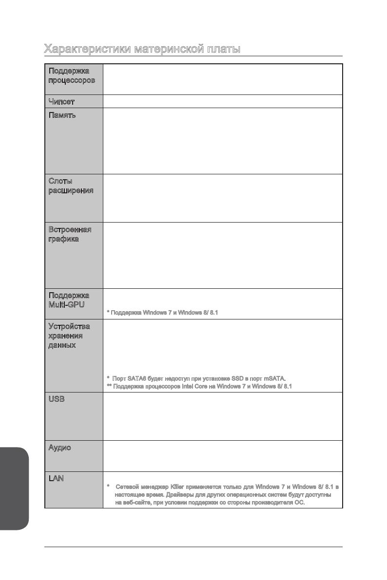
Характеристики материнской платы
Поддержка
процессоров
Поддержка процессоров Intel
®
Core™ Processors, и Intel
®
Pentium
®
и Celeron
®
4-го и 5-го поколения для сокета
LGA1150
■
Чипсет Intel
®
Z97 Express ■
Память 4x DDR3 слота памяти с поддержкой до 32ГБ
Поддержка DDR3 3000(OC)/ 2800(OC)/ 2666(OC)/ 2600(OC)/
2400(OC)/ 2200(OC)/ 2133(OC)/ 2000(OC)/ 1866(OC)/ 1600/
1333/ 1066 МГц
Двухканальная архитектура памяти
Поддержка non-ECC, небуферизованной памяти
Поддержка Intel
®
Extreme Memory Prole (XMP)
■
■
■
■
■
Слоты
расширения
3x слота PCIe 3.0 x16
Режим работы будет x16/ x0/ x0, x8/ x8/ x0, or x8/ x4/ x4.
Всегда устанавливайте карты расширения в PCI_E2
“снасала”.
4x слота PCIe 2.0 x1
■
—
■
Встроенная
графика
1x порт VGA, с поддержкой максимального разрешения
1920×1200 @ 60Гц, 24bpp
1x порт HDMI
®
, с поддержкой максимального разрешения
1x порт DVI-D, с поддержкой максимального разрешения
1920×1200 @ 60Гц, 24bpp
■
■
■
Поддержка
Multi-GPU
Поддержка Технологии 3-Way AMD CrossFire
TM
*
Поддержка Технологии 2-Way NVIDIA
®
SLI
TM
* Поддержка Windows 7 и Windows 8/ 8.1
■
■
Устройства
хранения
данных
Чипсет Intel Z97 Express
1x порт mSATA 6Gb/s*
6x портов SATA 6Гб/с (SATA1~6)*
Поддержка RAID 0, RAID1, RAID 5 и RAID 10
Поддержка Технологии Intel Smart Response, Технологии
Intel
®
Rapid Start и Технологии Intel Smart Connect**
* Порт SATA6 будет недоступ при установке SSD в порт mSATA.
** Поддержка процессоров Intel Core на Windows 7 и Windows 8/ 8.1
■
—
—
—
—
USB Чипсет Intel Z97 Express
6x портов USB 3.0 (4 порта на задней панели, 2 порта
доступны через внутренние USB 3.0 разъемы)
8x портов USB 2.0 (2 порта на задней панели, 6 порта
доступны через внутренние USB 2.0 разъемы)
■
—
—
Аудио Realtek
®
ALC1150 Codec
7.1-канальный High Denition Audio
Поддержка выход S/PDIF
■
—
—
LAN 1x Killer E2205 Гигабитный Сетевой контроллер*
* Сетевой менеджер Killer применяется только для Windows 7 и Windows 8/ 8.1 в
настоящее время. Драйверы для других операционных систем будут доступны
на веб-сайте, при условии поддержки со стороны производителя ОС.
■
Русский
Ru-3
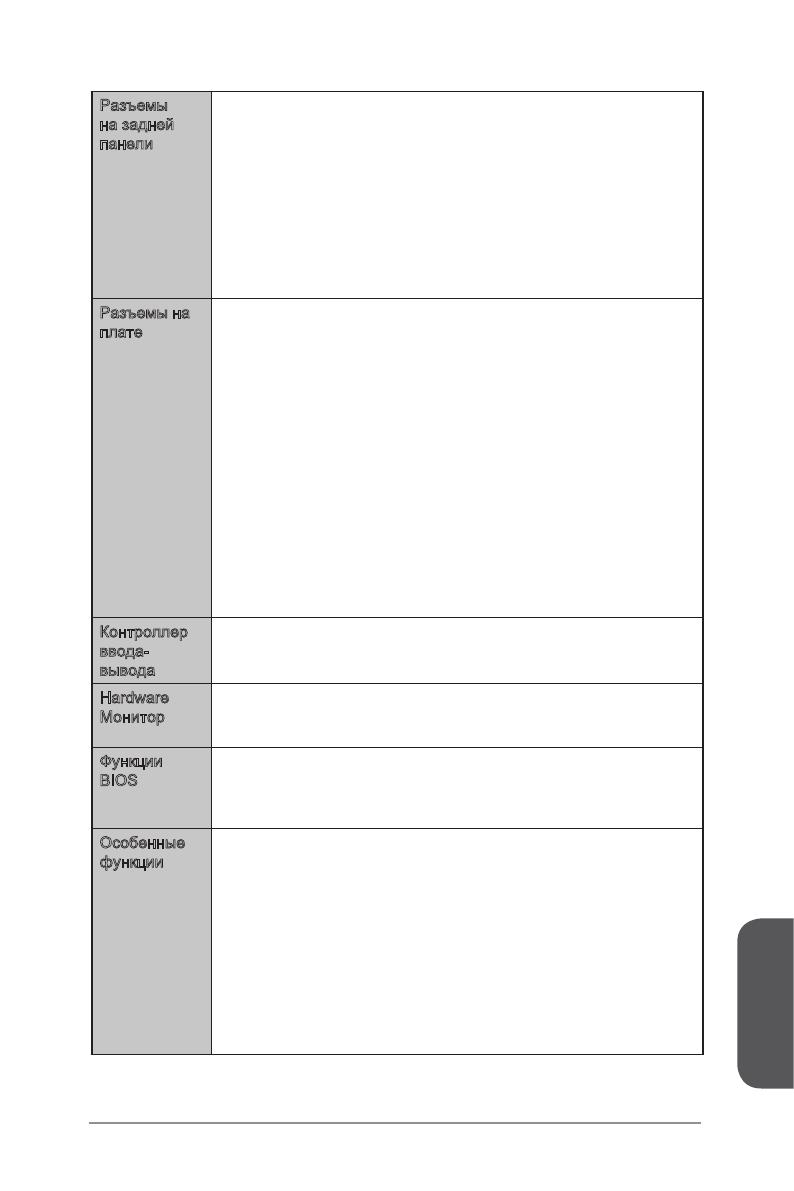
Разъемы
на задней
панели
1x комбинированный порт PS/2 клавиатуры/ мыши
2x порта USB 2.0
1x кнопка очистки данных CMOS
1x коаксиальный разъем S/PDIF ВЫХОД
1x оптический разъем S/PDIF ВЫХОД
1x порт VGA
1x порт DVI-D
1x порт HDMI
1x порт LAN (RJ45)
4x порта USB 3.0
6x OFC аудиоразъемов
■
■
■
■
■
■
■
■
■
■
■
Разъемы на
плате
1x 24-контактный ATX основной разъем питания
1x 8-контактный ATX 12В разъем питания
6x разъемов SATA 6Гб/с
3x разъема USB 2.0 (Поддержка 6 дополнительных портов
USB 2.0)
1x разъем USB 3.0 (Поддержка 2 дополнительных портов
USB 3.0)
2x 4-контактный разъем вентилятора ЦП
3x 4-контактные разъемы вентилятора системы
1x джампер очистки данных CMOS
1x аудиоразъем на передней панели
2x разъема панели системы
1x разъем модуля TPM
1x разъем последовательного порта
1x разъем датчика открытия корпуса
7x контактов для замера напряжения (7x контактов для
замера напряжения)
■
■
■
■
■
■
■
■
■
■
■
■
■
■
Контроллер
ввода-
вывода
NUVOTON NCT6779 Чип-контроллера■
Hardware
Mонитор
Детектирование температуры CPU/Системы
Детектирование скорости вентилятора CPU/Системы
Контроль скорости вентилятора CPU/Системы
■
■
■
Функции
BIOS
1x 64 Мб флэш
Мультиязычный интерфейс БИОС
ACPI 5.0, PnP 1.0a, SM BIOS 2.7, DMI 2.0
Multi-язык
■
■
■
■
Особенные
функции
Audio Boost
Killer Ethernet
Military Class 4
OC Genie 4
Click BIOS 4
NVIDIA SLI
AMD CrossFire
Sound Blaster Cinema
Total Fan Control
Порт игрового устройства
Smart Utilities
Command Center
■
■
■
■
■
■
■
■
■
■
■
■
Русский
Ru-4
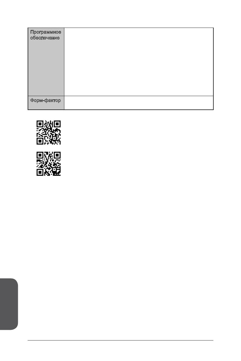
Программное
обеспечение
Драйверы
MSI
Command Center
Super Charger
Smart Utilities
Live Update 6
Fast Boot
7-ZIP
Intel Extreme Tuning Utility
Sound Blaster Cinema
Killer Network Manager
Norton Internet Security Solution
■
■
—
—
—
—
—
■
■
■
■
■
Форм-фактор ATX
12.0 дюймов x 9.6 дюймов (30.5 см x 24.4 см)
■
■
Последние сведения о поддержке процессора
можно получить по адресу http://www.msi com/
cpu-support/
Дополнительные сведения о совместимых компонентах
можно получить по адресу http://www.msi.com/test-report/
Русский
Ru-5
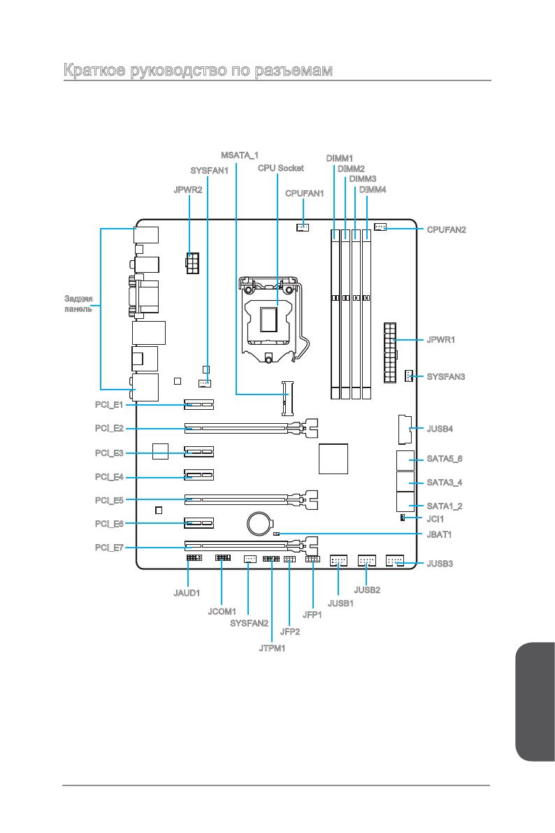
Краткое руководство по разъемам
CPUFAN2
JFP1
JUSB3
JAUD1
JCI1
PCI_E1
PCI_E2
PCI_E3
PCI_E4
DIMM2
DIMM1
DIMM3
DIMM4
JTPM1
JUSB1
JUSB2
JFP2
PCI_E5
PCI_E6
PCI_E7
JCOM1
JPWR1
SYSFAN3
JUSB4
SATA5_6
SATA3_4
SATA1_2
Задняя
панель
JBAT1
SYSFAN2
JPWR2
SYSFAN1
MSATA_1
CPU Socket
CPUFAN1

Русский
Ru-6
Справочное руководство по разъемам
Наименование порта Тип порта Страница
Разъемы на задней панели Порты ввода / вывода Ru-7
CPU Socket Разъем LGA1150 CPU
Ru-9
CPUFAN1~2,SYSFAN1~3 Разъемы питания вентиляторов Ru
-19
DIMM1~4 Слоты для модулей памяти DDR3 Ru
-13
JAUD1 Аудиоразъем на передней панели Ru
-23
JBAT1 Джампер очистки данных CMOS Ru
-26
JCI1 Разъем датчика открытия корпуса Ru
-22
JCOM1 Разъем последовательного порта Ru
-24
JFP1, JFP2 Разъемы передней панели Ru
-20
JPWR1~2 Разъемы питания ATX Ru
-15
JTPM1 Разъем модуля TPM Ru
-21
JUSB1~3 Разъемы расширения USB 2.0 Ru
-21
JUSB4 Разъем расширения USB 3.0 Ru
-21
MSATA_1 mSATA Слот Ru
-23
PCI_E1~E7
Слот расширения PCIe Ru-16
SATA1~6 Pазъем SATA Ru
-18
Русский
Ru-7
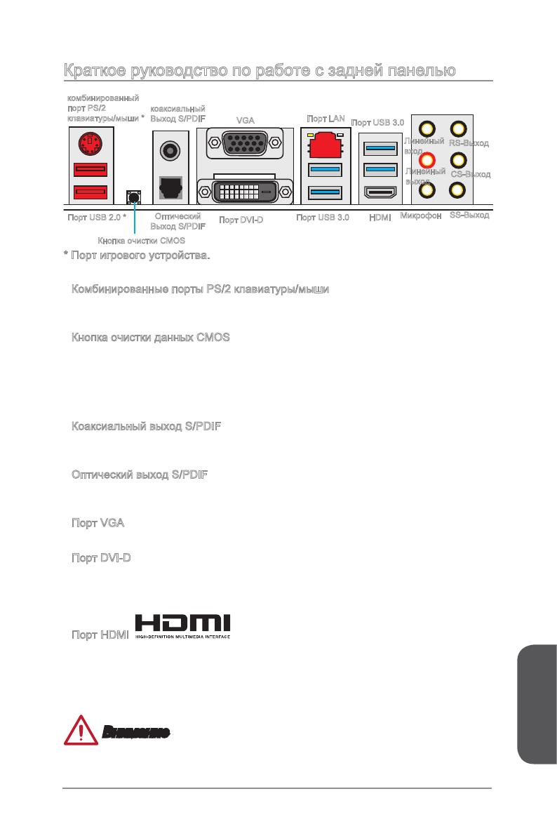
Краткое руководство по работе с задней панелью
Комбинированные порты PS/2 клавиатуры/мыши
Комбинированный разъем DIN PS/2
®
для подключения мыши/клавиатуры с
интерфейсом PS/2
®
.
Кнопка очистки данных CMOS
На плате установлена CMOS-память с питанием от внешней батареи, хранящая
данные о конфигурации системы. С помощью памяти CMOS операционная
система (ОС) автоматически загружается каждый раз при включении. Если у вас
возникает необходимость сбросить конфигурацию системы (очистить данные
CMOS), воспользуйтесь этой кнопкой.
Коаксиальный выход S/PDIF
Разъем S/PDIF (цифровой интерфейс Sony/Philips) предназначен для передачи
цифрового аудио на внешние громкоговорители через коаксиальный кабель.
Оптический выход S/PDIF
Разъем S/PDIF (цифровой интерфейс Sony/Philips) предназначен для передачи
цифрового аудио на внешние громкоговорители через оптоволоконный кабель.
Порт VGA
Разъем DB15 гнездового типа для подключения монитора.
Порт DVI-D
Разъем DVI-D (цифровой видеоинтерфейс) подключается к ЖК или ЭЛТ
монитору с помощью переходника. Подробную информацию о подключении
монитора см. в руководстве к монитору.
Порт HDMI
Мультимедийный интерфейс высокой четкости (HDMI) представляет собой
полностью цифровой аудио- видеоинтерфейс, позволяющий передавать
несжатые потоки данных. Интерфейс HDMI обеспечивает передачу ТВ-сигнала
по одному кабелю в любом формате, включая телевидение стандартной,
повышенной и высокой четкости, а также многоканальный цифровой звукe.
Внимание
Данная платформа поддерживает функцию dual-display(два дисплея)/ triple-
display (три дисплея) с помощью портов вывода интегрированной графики.
▶
▶
▶
▶
▶
▶
▶
Оптический
Выход S/PDIF
Линейный
вход
Линейный
выход
Микрофон
RS-Выход
CS-Выход
SS-Выход
Порт USB 3.0
Кнопка очистки CMOS
Порт LAN
комбинированный
порт PS/2
клавиатуры/мыши *
Порт USB 2.0 *
Порт DVI-D
HDMI
Порт USB 3.0
VGA
коаксиальный
Выход S/PDIF
* Порт игрового устройства.
Русский
Ru-8
VGA+DVI-D DVI-D+HDMI HDMI+VGA HDMI+VGA+DVI-D
Режим расширения
(Расширение рабочего
стола на другой
монитор)
◯ ◯ ◯ ◯
режим клонирования
(Изображения на всех
мониторах совпадают)
◯ ◯ ◯ ◯
Порт USB 2.0
Порт USB 2.0 предназначен для подключения USB 2.0-устройств, таких как
клавиатура, мышь и другие USB 2.0-совместимые устройства.
Порт USB 3.0
Порт USB 3.0 обратно совместим с устройствами USB 2.0. Поддержка передачи
данных со скоростью до 5 Гбит/с (SuperSpeed).
Внимание
Для использования устройств USB 3.0 их следует подключать к порту USB 3.0.
Используемый USB-кабель должен быть совместим со стандартом USB 3.0.
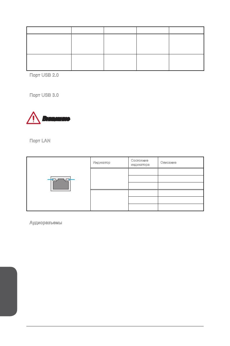
Порт LAN
Стандартный разъем RJ-45 для подключения к локальной вычислительной сети
(LAN).
LINK/ACT
LED
SPEED
LED
Индикатор
Состояние
индикатора
Описание
Link/ Activity LED
(Подключение/
Работа индикатора)
Выкл. Не подключен
Желтый Подключен
Мигает Передача данных
Speed LED
(Скорость передачи
данных)
Выкл. 10 Мбит/с подключение
Зеленый 100 Мбит/с подключение
Оранжевый 1 Гбит/с подключение
Аудиоразъемы
Эти разъемы используются для подключения аудиоустройств.
Линейный вход: Служат для подключения внешних источников звукового
сигнала.
Линейный выход: Разъем для подключения динамиков или наушников.
Микрофон: Разъем для подключения микрофона.
Выход RS-Out: Выход на задние колонки пространственного звука в режи-
ме 4/ 5.1/ 7.1.
Выход CS-Out: Выход на центральную колонку и сабвуфер в режиме 5.1/
7.1.
Выход SS-Out: Выход на боковые колонки пространственного звука в ре-
жиме 7.1.
▶
▶
▶
▶
■
■
■
■
■
■
Русский
Ru-9
ЦП (центральный процессор)
Внимание
Перегрев
Перегревание может привести к серьезному повреждению процессора и
материнской платы. Всегда проверяйте работоспособность вентилятора для
защиты процессора от перегревания. При установке вентилятора нанесите
ровный слой термопасты (или термоленту) между ЦП и вентилятором для
увеличения теплопередачи.
Замена ЦП
При замене процессора всегда отключайте блок питания системы и вынимайте
шнур питания из розетки, чтобы избежать повреждения процессора.
Разгон
Эта системная плата разработана с учетом возможности «разгона». Перед
выполнением разгона системы убедитесь в том, что все компоненты системы
смогут выдержать разгон. Производитель не рекомендует использовать
параметры, выходящие за пределы технических характеристик устройств.
Гарантия MSI не распространяется на повреждения и другие возможные
последствия ненадлежащей эксплуатации и несоблюдения технических
характеристик изделия.
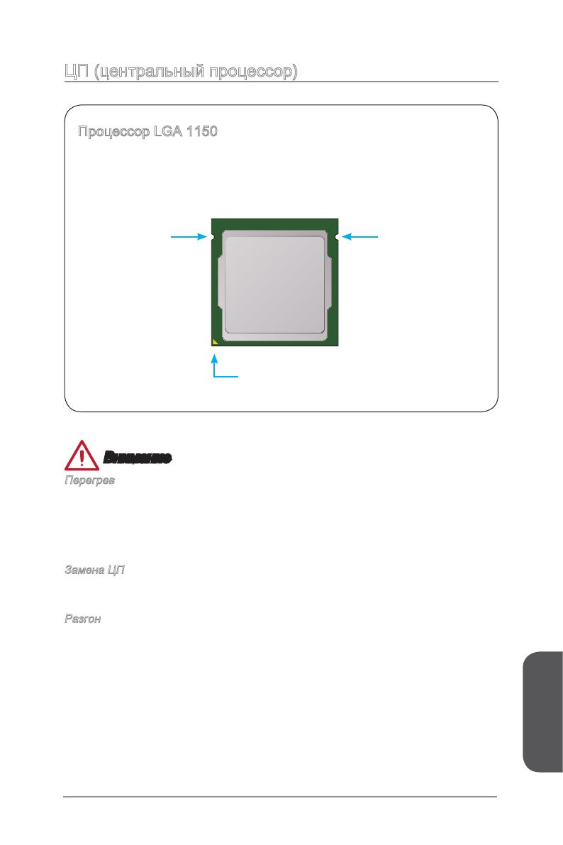
Процессор LGA 1150
На поверхности процессора LGA 1150 имеются два знака совмещения и
золотой треугольник для правильной установки процессора относительно
материнской платы. Золотой треугольник указывает на контакт 1.
Выемка
Золотой треугольник указывает на контакт 1
Выемка
Русский
Ru-10
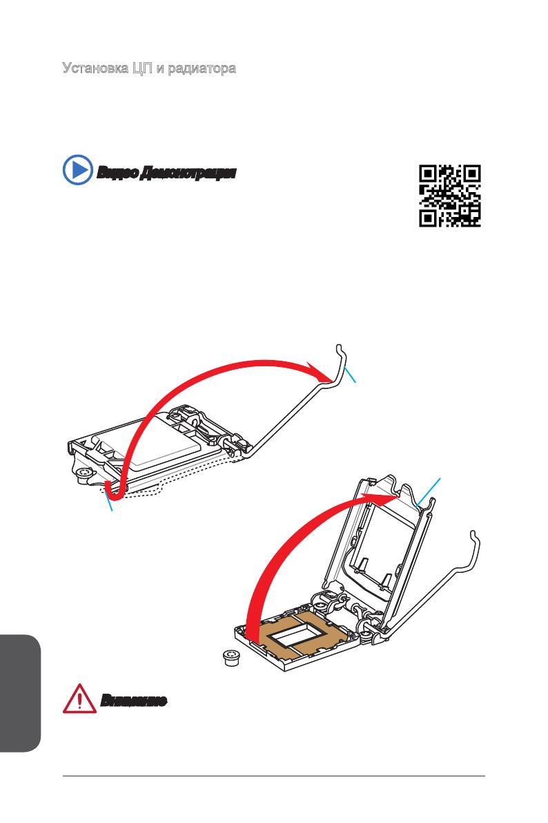
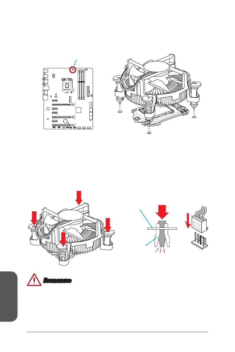
Установка ЦП и радиатора
При установке процессоора обязательно установите радиатор ЦП.Радиатор ЦП
предупреждает перегревание и обеспечивает стабильность работы системы.
Ниже представлены инструкции по правильной установке процессора и
радиатора ЦП. Неправильная установка приводит к выходу из строя процессора
и материнской платы.
1. Отцепите и полностью поднимите рычаг фиксации.
2. При подъеме рычага фиксации автоматически поднимается прижимная
пластина.
Удерживающая петля
Рычаг фиксации
Рычаг фиксации
Внимание
Не трогайте контакты разъема или нижней части процессора.
Видео Демонстрация
Смотрите видео,чтобы узнать как установить процессор и кулер:
http://youtu.be/bf5La099urI
Русский
Ru-11
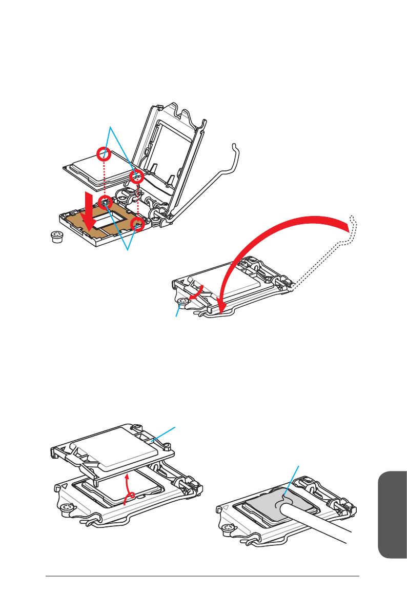
3. Совместите выемки на процессоре с ключами совмещения на сокете.
Опустите процессор вниз без наклона. Движение процессора в сокете
недопустимо. Проверьте надежность установки процессора в сокете.
4. Закройте и сдвиньте прижимную пластину под ручку удержания. Закройте и
зацепите рычаг фиксации.
Ключи совмещения
Выемки процессора
Ручка удержания
5. При нажатии на рычаг фиксации защитная крышка автоматически выскочит
из гнезда процессора. Не выбрасывайте защитную крышку. Всегда
устанавливайте защитную крышку, если процессор вынимается из сокета.
6. Равномерно нанесите тонкий слой термопасты (или термоленту) на верхнюю
крышку процессора. Это позволит увеличить теплопередачу и предотвратит
перегрев процессора.
Защитная крышка
Термопаста
Русский
Ru-12
Внимание
Перед включением системы проверьте герметичность соединения между
процессором и радиатором.
Если процессор не установлен, всегда защищайте контакты процессорного
сокета пластиковой крышкой.
Если вы приобрели отдельно процессор и процессорный кулер, подробное
описание установки см. в документации в данному кулеру.
•
•
•
7. Найдите разъем для подключения вентилятора ЦП на материнской плате.
8. Установите кулер на материнскую плату, направив его кабель в сторону
разъема для подключения вентилятора.
9. Нажмите на радиатор сверху так, чтобы закрепить четыре защелки в
отверстиях на материнской плате. Нажмите на защелки для закрепления
вентилятора. Каждая из защелок фиксируется с характерным щелчком.
10. Осмотрите материнскую плату и определите правильность закрепления
зажимов.
11. И, наконец, подключите кабель вентилятора процессора к разъему
вентилятора на системной плате.
Материнская плата
Крепежный
конец
Разъем подключения
вентилятора
Русский
Ru-13
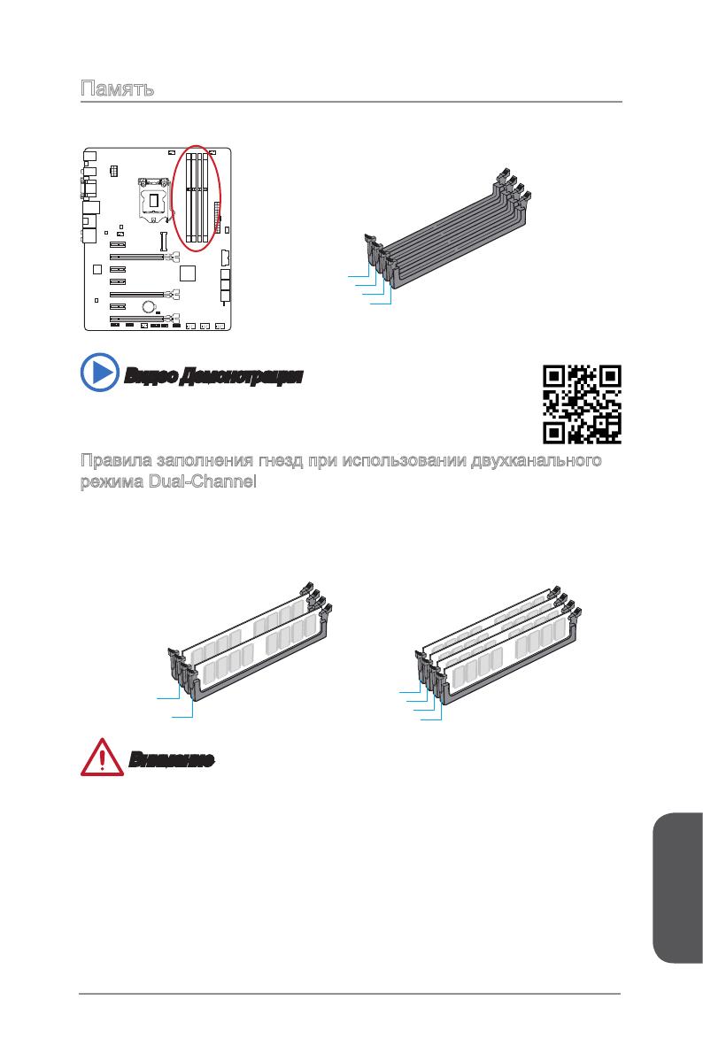
Память
Разъемы DIMM предназначены для установки модулей памяти.
DIMM1
DIMM2
DIMM3
DIMM4
Видео Демонстрация
Смотрите видео,чтобы узнать как установить память по указанному
адресу.
Правила заполнения гнезд при использовании двухканального
режима Dual-Channel
В двухканальном режиме модули памяти могут одновременно передавать и
получать данные по двум каналам шины. Включение двухканального режима
Dual-Channel может повысить производительность системы. На рисунках ниже
показаны правила заполнения гнезд памяти при использовании двухканального
режима Dual-Channel.
DIMM2
DIMM4
DIMM1
DIMM2
DIMM3
DIMM4
Внимание
Модули DDR3 не взаимозаменяемы с модулями DDR2, стандарт DDR3 не
поддерживает обратную совместимость. Модули памяти DDR3 следует
устанавливать в разъемы DDR3 DIMM.
Для обеспечения стабильной работы системы в двухканальном режиме
устанавливаются модули памяти одинакового типа и емкости.
В связи со спецификой использования ресурсов микропроцессора, при
установке модулей памяти емкостью 8 ГБ во все разъемы DIMM системная
память определяется только до 31+ ГБ (неполные 32 ГБ).
•
•
•
Русский
Ru-14
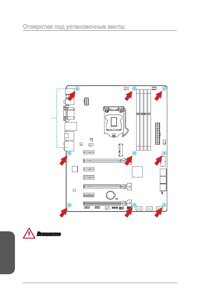
Отверстия под установочные винты
Для установки материнской платы на монтажной плате системного блока
сначала установите необходимые установочные стойки. Если в комплект
поставки системного блока входит задняя панель ввода-вывода, замените
ее задней панелью ввода-вывода, которая поставляется с материнской
платой. Задняя панель ввода-вывода без труда устанавливается в системном
блоке компьютера без применения винтов. Совместите установочные стойки
монтажной платы с отверстиями под установочные винты на материнской
плате и закрепите материнскую плату винтами, которые поставляются вместе с
системным блоком. Ниже показано расположение отверстий под установочные
винты. Дополнительную информацию см. в руководстве к системному блоку.
Внимание
Положите материнскую плату на ровную и чистую поверхность.
Во избежание повреждения материнской платы, закрепляйте электронные
компоненты на установочных стойках, избегая их соприкосновения с
системным блоком.
Проверьте надежность крепления всех металлических компонентов на
материнской плате или внутри системного блока. Незакрепленные детали
могут привести к короткому замыканию материнской платы.
•
•
•
Разъемы ввода-вывода должны
быть направлены в сторону
задней панели системного блока.
Совместите их с отверстиями на
задней панели ввода-вывода.
Русский
Ru-15
Электропитание
Видео Демонстрация
Смотрите видео,чтобы узнать как установить разъем питания.
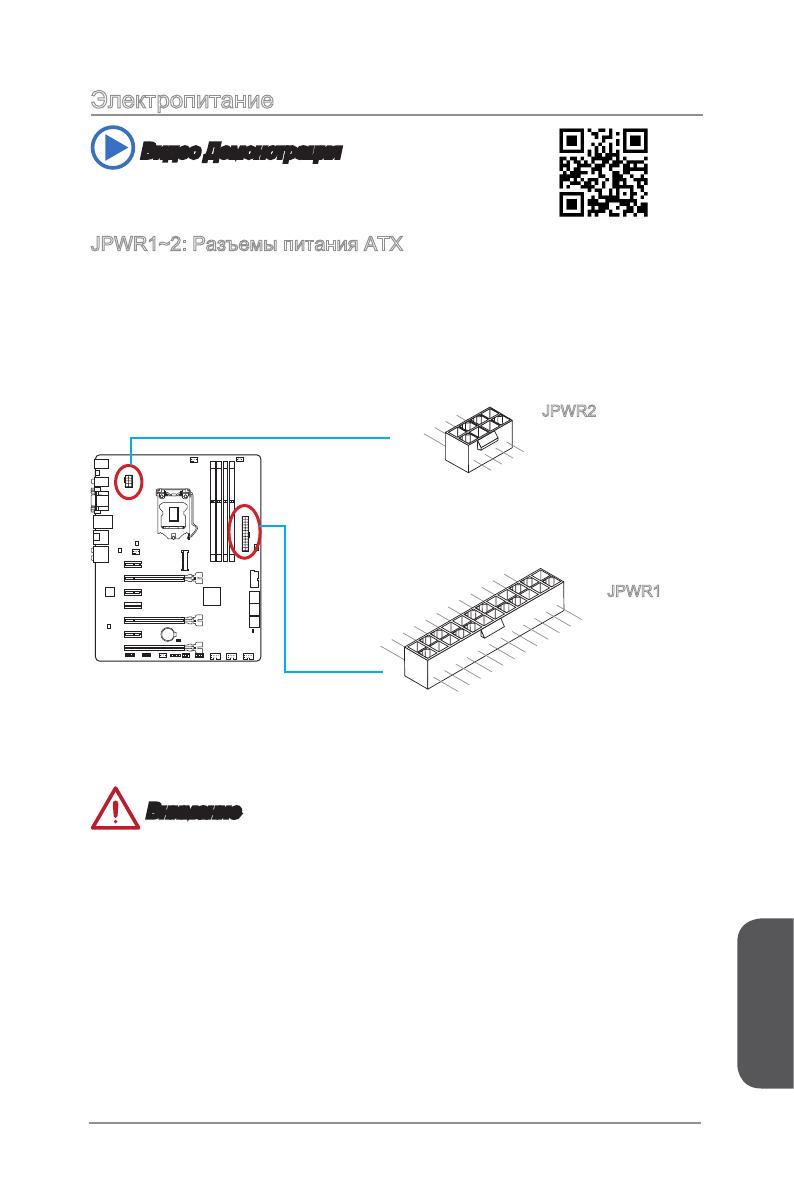
JPWR1~2: Разъемы питания ATX
Эти разъемы предназначены для подключения разъема питания ATX. Для
подключения ATX разъема питания совместите кабель питания с разъемом и
прочно закрепите его. При правильном выполнении подключения защелка на
кабеле питания закрепляется в силовом разъеме материнской платы.
13.+3.3
V
1.+3.3
V
14.-12V
2.+3.3
V
15.Ground
3
.Ground
16.PS—ON
#
4.+5
V
17.Ground
5
.Ground
18.Ground
6.+5
V
19.Ground
7
.Ground
22.+5
V
10.+12V
20.Res
8.PW
R O
K
23.+5
V
11
.+12V
21.+5
V
9.5VSB
24.Ground
12.+3.3
V
7.+12V
3.Ground
5.+12V
1.
Ground
8.+12V
4
.Ground
6.+12V
2
.Ground
JPWR2
JPWR1
Внимание
Для обеспечения стабильной работы системной платы проверьте надежность
подключения всех кабелей питания к соответствующему блоку питания АТХ.
Русский
Ru-16
Слоты расширения
Данная материнская плата содержит множество разъемов для установки плат
расширения, в частности, дискретных видеокарт или звуковых карт.
PCI_E1~E7: Слот Расширения PCIe
Слот PCIe поддерживает платы расширения с интерфейсом PCIe.
PCIe 2.0 x1 слот
PCIe 3.0 x16 слот
Внимание
Перед установкой или извлечением плат расширения убедитесь, что шнур
питания отключен от электрической сети. Прочтите документацию на карту
расширения и выполните необходимые дополнительные аппаратные или
программные изменения для данной карты.
Русский
Ru-17
Видео/ Установка дискретной видеокарты
По умолчанию, данная плата использует графическое ядро интегрированное
в CPU, но Вы так же можете значительно повысит графическую
производительность системы, путем добавление одной или нескольких
дискретных видеокарт в слоты расширения. Для лучшей совместимости
рекомендуется использовать графические карты MSI.
Видео Демонстрация
Смотрите видео,чтобы узнать как установить видеокарту на слоте
PCIe x16 с замком.
Установка одной видеокарты
Определите тип слота расширения, который используется видеокартой.
Найдите соответствующий слот(ы) на материнской плате. Выньте защитную
крышку слота(ов) расширения из корпуса системного блока.
Расположите видеокарту над слотом(ами) для расширения так, чтобы порты
подключения мониторов были направлены ко внешней стороне системного
блока. Для установки одной видеокарты рекомендуется использовать слот
PCI_E2.
Вставьте видеокарту в слот(ы) расширения. В случае правильной установки
карты, защелка(и) на слоте(ах) расширения должны защелкнуться.
При необходимости, прикрутите видеокарту к корпусу системного блока
винтом. Для некоторых видеокарт требуется подключение непосредственно к
блоку питания отдельным кабелем.
Дополнительные инструкции по установке драйверов и настройке
специальных параметров представлены в руководстве пользователя к
видеокарте.
1.
2.
3.
4.
5.
Русский
Ru-18
Внутренние разъемы
SATA1~6: Разъем SATA
Данный разъем является высокоскоростным интерфейсом SATA. К любому
разъему SATA можно подключить одно устройство SATA. К устройствам SATA
относятся жесткие диски, твердотельные накопители и накопители на оптических
дисках (компакт-диски/ DVD-диски/ Blu-Ray-диски).
Видео Демонстрация
Смотрите видео, чтобы узнать как установить
SATA жесткие диски.
SATA6
SATA5
SATA2
SATA1
SATA4
SATA3
Внимание
Порт SATA6 будет недоступ при установке твердотельного накопители в порт
mSATA.
Многие устройства SATA требуют подключения к источнику питания с
помощью кабеля питания. К таким устройствам относятся жесткие диски,
твердотельные накопители и накопители на оптических дисках (компакт-диски/
DVD-диски/ Blu-Ray-диски). Дополнительную информацию можно получить в
руководствах к соответствующим устройствам.
Во многих системных блоках устройства SATA большого размера (в том числе,
жесткие диски, твердотельные накопители и накопители на оптических дисках)
прикрепляются с помощью винтов. Дополнительные инструкции по установке
см. в руководствах к системному блоку или устройству SATA.
Избегайте перегибов кабеля SATA под прямым углом. В противном случае,
возможна потеря данных при передаче.
Кабели SATA оснащены одинаковыми вилками с обеих сторон. Однако для
экономии занимаемого пространства рекомендуется к материнской плате
подключать плоский разъем.
•
•
•
•
•
/
на других языках
Похожие инструкции
Другие инструкции
-
Contents
-
Table of Contents
-
Bookmarks
Quick Links
P45 Neo/ G45 Neo
/ P43 Neo Series
MS-7519 (v1.X) Mainboard
G52-75191X1
i
Related Manuals for MSI G45
Summary of Contents for MSI G45
-
Page 1
P45 Neo/ G45 Neo / P43 Neo Series MS-7519 (v1.X) Mainboard G52-75191X1… -
Page 2: Copyright Notice
Alternatively, please try the following help resources for further guidance. Visit the MSI website for FAQ, technical guide, BIOS updates, driver updates, an d ot h er i n f orm at i on: func=service Contact our technical staff at: http://ocss.msi.com.tw…
-
Page 3: Safety Instructions
Safety Instructions Always read the safety instructions carefully. Keep this User’s Manual for future reference. Keep this equipment away from humidity. Lay this equipment on a reliable flat surface before setting it up. The openings on the enclosure are for air convection hence protects the equip- ment from overheating.
-
Page 4: Fcc-B Radio Frequency Interference Statement
FCC-B Radio Frequency Interference Statement T h is eq uip men t h as been tested and found to c omply with the limits for a Class B digital device, pursuant to Part 15 of the FCC Rules. These limits are designed to provide reasonable protection against harmful interference in a residential installation.
-
Page 5: Weee (Waste Electrical And Electronic Equipment) Statement
WEEE (Waste Electrical and Electronic Equipment) Statement…
-
Page 8: Table Of Contents
Copyright Notice … ii Trademarks … ii Revision History … ii Technical Support … ii Safety Instructions … iii FCC-B Radio Frequency Interference Statement … iv W EEE (Waste Electrical and Electronic Equipment) Statement … v Chapter 1. Getting Started … 1-1 Mainboard Specifications …
-
Page 9
Appendix B Dual Core Center … B-1 Activating Dual Core Center … B-2 Main … B-3 DOT (Dynamic OverClocking) … B-5 Clock … B-6 Voltage … B-7 FAN Speed … B-8 Temperature … B-9 User Profile … B-10… -
Page 11: Chapter 1. Getting Started
Getting Started Chapter 1 Getting Started Thank you for choosing the P45 Neo/ G45 Neo/ P43 Neo Series (MS-7519 v1.X) ATX mainboard. The P45 Neo/ G45 Neo/ P43 Neo Series mainboards are based ® on Intel P45/ G45/ P43 & ICH10 chipsets for optimal ®…
-
Page 12: Mainboard Specifications
— Supports PIO, Bus Master operation mode SATA — 6 SATAII ports by ICH10 (SATA1~6) — Supports storage and data transfers at up to 3 Gb/s 1394 (optional) — Supports 1394 by JMicron JMB381 ® P45/ G45/ P43 chipset ® ICH10 chipset ® ALC888…
-
Page 13
— 1 PS/2 mouse port — 1 PS/2 keyboard port — 1 Parallel port — 1 Serial port — 1 VGA port (for G45 only) — 4 USB 2.0 Ports — 1 LAN jack (10/100/1000) — 6 flexible audio jacks… -
Page 14: Mainboard Layout
PCI _E1 RTL8111C PCI _E2 PCI _E3 Chip PCI 1 PCI 2 ALC888 PCI 3 JAUD1 JCD1 JSP1 P45 Neo/ G45 Neo/ P43 Neo Series (MS-7519 v1.X) ATX Mainboard P45/ G45/P43 Intel ICH10 JMicron JMB381 (optional) FDD 1 SYSFAN1 CPUFAN1 JMicron…
-
Page 15: Packing Checklist
MSI motherboard Power Cable User’s Guide and Quick Guide * The pictures are for reference only and may vary from the packing contents of the product you purchased. MSI Driver/Utility CD SATA Cable Getting Started Back IO Shield IDE Cable…
-
Page 17: Chapter 2. Hardware Setup
Hardware Setup Chapter 2 Hardware Setup This chapter provides you with the information about hardware setup procedures. While doing the installation, be careful in holding the components and follow the installation procedures. For some components, if you install in the wrong orientation, the components will not work properly.
-
Page 18: Quick Components Guide
M S-7519 M ainboard Quick Components Guide JB1/JB2, p.2-19 JPWR2, p.2-9 Back Panel, p.2-10 PCIE, p.2-20 PCI, p.2-20 JAUD1, p.2-17 JCD1, p.2-16 JSP1, p.2-15 SYSFAN1, CPU, p.2-3 p.2-14 CPUFAN1, p.2-14 FDD1, JBAT1, p.2-19 p.2-12 J1394_1, JTPM1, p.2-15 p.2-17 DDR2 DIMMs, p.2-7 JPWR1, p.2-9…
-
Page 19: Cpu (Central Processing Unit)
W hen you are installing the CPU, make sure to install the cooler to prevent overheating. If you do not have the CPU cooler, consult your dealer before turning on the computer. For the latest information about CPU, please visit http://global.msi.com.tw/index.php? func=cpuform Important Overheating Overheating will seriously damage the CPU and system.
-
Page 20
M S-7519 M ainboard CPU & Cooler Installation W hen you are installing the CPU, make sure the CPU has a cooler attached on the top to prevent overheating. Meanwhile, do not forget to apply some thermal paste on CPU before installing the heat sink/cooler fan for better heat dispersion. Follow the steps below to install the CPU &… -
Page 21
5. Lift the load lever up and open the load plate. 7. Visually ins pect if the CPU is seated well into the socket. If not, take out the CPU with pure vertical motion and reinstall. Hardware Setup 6. After confirming the CPU direction for correct mating, put down the CPU in the socket housing frame. -
Page 22
M S-7519 M ainboard 9. Press down the load lever lightly onto the load plate, and then se- cure the lever with the hook under retention tab. 11. Press the four hooks down to fas- ten the cooler. Then rotate the lock- ing switch (refer to the correct di- rection marked on it) to lock the hooks. -
Page 23: Memory
Memory These DIMM slots are used for installing memory modules. For more information on compatible components, please visit http://global.msi.com. tw/index.php?func=testreport DDR2 240-pin, 1.8V Dual-Channel Memory Population Rules In Dual-Channel mode, the memory modules can transmit and receive data with two data bus lines simultaneously.
-
Page 24: Installing Memory Modules
M S-7519 M ainboard Installing Memory Modules 1. The memory module has only one notch on the center and will only fit in the right orientation. 2. Insert the memory module vertically into the DIMM slot. Then push it in until the golden finger on the memory module is deeply inserted in the DIMM slot.
-
Page 25: Power Supply
Power Supply ATX 24-Pin Power Connector: JPWR1 This connector allows you to connect an ATX 24-pin power supply. To connect the ATX 24-pin power supply, make sure the plug of the power supply is inserted in the proper orientation and the pins are aligned.
-
Page 26: Back Panel
The serial port is a 16550A high speed communications port that sends/ receives 16 bytes FIFOs. You can attach a serial mouse or other serial devices directly to the connector. VGA Port (for G45) The DB15-pin female connector is provided for monitor. 1394 Port (optional) The IEEE1394 port on the back panel provides connection to IEEE1394 devices.
-
Page 27
The standard RJ-45 LAN jack is for connection to the Local Area Network (LAN). You can con- nect a network cable to it. Color LED State Left Yellow On (steady state) On (brighter & pulsing) The computer is communicating with another computer on the LAN. Green Right Orange… -
Page 28: Connectors
M S-7519 M ainboard Connectors Floppy Disk Drive Connector: FDD1 This connector supports 360KB, 720KB, 1.2MB, 1.44MB or 2.88MB floppy disk drive. IDE Connector: IDE1 This connector supports IDE hard disk drives, optical disk drives and other IDE devices. Important If you install two IDE devices on the same cable, you must configure the drives separately to master / slave mode by setting jumpers.
-
Page 29
Hardware Setup Serial ATA Connector: SATA1~6 This connector is a high-speed Serial ATA interface port. Each connector can connect to one Serial ATA device. SATA3 SATA1 SATA5 SATA2 SATA4 SATA6 Important Please do not fold the Serial ATA cable into 90-degree angle. Otherwise, data loss may occur during transmission. -
Page 30
M S-7519 M ainboard Fan Power Connectors: CPUFAN1, SYSFAN1, SYSFAN2 The fan power connectors support system cooling fan with +12V. W hen connecting the wire to the connectors, always note that the red wire is the positive and should be connected to the +12V; the black wire is Ground and should be connected to GND. If the mainboard has a System Hardware Monitor chipset on-board, you must use a specially designed fan with speed sensor to take advantage of the CPU fan control. -
Page 31: Ieee1394 Connector: J1394_1
IEEE1394 Connector: J1394_1 (optional) This connector allows you to connect the IEEE1394 device via an optional IEEE1394 bracket. J1394_1 S/PDIF-Out Connector: JSP1 This connector is used to connect S/PDIF (Sony & Philips Digital Interconnect Format) interface for digital audio transmission. Hardware Setup Pin Definition SIGNAL…
-
Page 32: Cd-In Connector
M S-7519 M ainboard Front Panel Connectors: JFP1, JFP2 These connectors are for electrical connection to the front panel switches and LEDs. The JFP1 is compliant with Intel Power Power Switch JFP1 Reset Switch Speaker JFP2 Power CD-In Connector: JCD1 This connector is provided for external audio input.
-
Page 33
Front Panel Audio Connector: JAUD1 This connector allows you to connect the front panel audio and is compliant with ® Intel Front Panel I/O Connectivity Design Guide. SIGNAL MIC_L MIC_R LINE out_R MIC_JD Front_JD LINE out_L LINEout_JD TPM Module Connector: JTPM1 (optinoal) This connector connects to a TPM (Trusted Platform Module) module (optional). -
Page 34
M S-7519 M ainboard Front USB Connector: JUSB1~4 These connectors, compliant with Intel connecting high-speed USB interface peripherals such as USB HDD, digital cameras, M P3 players, printers, modems and the like. JUSB1~4 Important Note that the pins of VCC and GND must be connected correctly to avoid possible damage. -
Page 35: Jumpers
Jumpers Clear CMOS Jumper: JBAT1 There is a CMOS RAM onboard that has a power supply from an external battery to keep the data of system configuration. W ith the CMOS RAM, the system can auto- matically boot OS every time it is turned on. If you want to clear the system configuration, set the jumper to clear data.
-
Page 36: Slots
M S-7519 M ainboard Slots PCI (Peripheral Component Interconnect) Express Slot The PCI Express slot supports the PCI Express interface expansion card. The PCI Express 2.0x 16 supports up to 8.0 GB/s transfer rate. The PCI Express x 1 supports up to 250 MB/s transfer rate. PCI Express x 1 Slot PCI (Peripheral Component Interconnect) Slot The PCI slot supports LAN card, SCSI card, USB card, and other add-on cards that…
-
Page 37: Pci Interrupt Request Routing
PCI Interrupt Request Routing The IRQ, acronym of interrupt request line and pronounced I-R-Q, are hardware lines over which devices can send interrupt signals to the microprocessor. The PCI IRQ pins are typically connected to the PCI bus pins as follows: Order 1 PCI Slot 1 INT F#…
-
Page 39: Chapter 3 Bios Setup
Chapter 3 BIOS Setup This chapter provides information on the BIOS Setup program and allows you to configure the system for optimum use. You may need to run the Setup program when: ² An error message appears on the screen during the system booting up, and requests you to run SETUP.
-
Page 40: Entering Setup
M S-7519 M ainboard Entering Setup Power on the computer and the system will start POST (Power On Self Test) process. W hen the message below appears on the screen, press <DEL> key to enter Setup. Press DEL to enter SETUP If the message disappears before you respond and you still wish to enter Setup, restart the system by turning it OFF and On or pressing the RESET button.
-
Page 41: Control Keys
Control Keys < > Move to the previous item < > Move to the next item < > Move to the item in the left hand < > Move to the item in the right hand <Enter> Select the item <Esc>…
-
Page 42: The Main Menu
M S-7519 M ainboard The Main Menu Standard CM OS Features Use this menu for basic system configurations, such as time, date etc. Advanced BIOS Features Use this menu to setup the items of AMI Integrated Peripherals Use this menu to specify your settings for integrated peripherals. Power M anagement Setup Use this menu to specify your settings for power management.
-
Page 43
Load Optimized Defaults Use this menu to load the default values set by the mainboard manufacturer specifi- cally for optimal performance of the mainboard. Save & Exit Setup Save changes to CMOS and exit setup. Exit Without Saving Abandon all changes and exit setup. BIOS Setup… -
Page 44: Standard Cmos Features
M S-7519 M ainboard Standard CMOS Features The items in Standard CMOS Features Menu includes some basic setup items. Use the arrow keys to highlight the item and then use the <PgUp> or <PgDn> keys to select the value you want in each item. Date (MM:DD:YY) This allows you to set the system to the date that you want (usually the current date).
-
Page 45
Device / Vendor / Size It will showing the device information that you connected to the SATA connector. LBA/Large M ode This allows you to enable or disable the LBA Mode. Setting to Auto enables LBA mode if the device supports it and the devices is not already formatted with LBA mode disabled. -
Page 46
M S-7519 M ainboard Halt On The setting determines whether the system will stop if an error is detected at boot. W hen the system stops for the errors preset, it will halt on for 15 seconds and then automatically resume its operation. Available options are: [All Errors] [No Errors] System Information… -
Page 47: Advanced Bios Features
Advanced BIOS Features BIOS Flash Protection This function protects the BIOS from accidental corruption by unauthorized users or computer viruses. W hen enabled, the BIOS’ data cannot be changed when attempt- ing to update the BIOS with a Flash utility. To successfully update the BIOS, you’ll need to disable this Flash BIOS Protection function.
-
Page 48
M S-7519 M ainboard IOAPIC Function This field is used to enable or disable the APIC (Advanced Programmable Interrupt Controller). Due to compliance with PC2001 design guide, the system is able to run in APIC mode. Enabling APIC mode will expand available IRQ resources for the system. MPS Table Version This field allows you to select which MPS (Multi-Processor Specification) version to be used for the operating system. -
Page 49
HPET The HPET (High Precision Event Timers) is a component that is part of the chipset. You can enable it, and it will provide you with the means to get to it via the various ACPI methods. Boot Sequence Press <Enter> to enter the sub-menu and the following screen appears: 1st/ 2nd Boot Device The items allow you to set the first/ second boot device where BIOS attempts to load the disk operating system. -
Page 50
M S-7519 M ainboard Intel Robson Configuration Press <Enter> to enter the sub-menu and the following screen appears: Intel Robson This item is used to enable/ disable Intel Robson technology. Intel Robson tech- nology is turbo memory technology that can let the users to enable operation system without accessing hard disk frequenctly. -
Page 51: Integrated Peripherals
Integrated Peripherals USB Controller This setting allows you to enable/disable the onboard USB controller. USB Device Legacy Support Select [Enabled] if you need to use a USB-interfaced device in the operating system. Onboard LAN Controller This item is used to enable/disable the onboard 1st LAN controller . LAN Option ROM This item is used to decide whether to invoke the Boot ROM of the LAN controller.
-
Page 52
M S-7519 M ainboard PCI IDE BusMaster This item allows you to enable/ disable BIOS to used PCI busmastering for reading/ writing to IDE drives. On-Chip SATA Controller These items allow users to enable or disable the SATA controller. RAID M ode This item allows you to configure SATA RAID mode. -
Page 53: Power Management Setup
Power Management Setup Important S3-related functions described in this section are available only when your BIOS supports S3 sleep mode. ACPI Function This item is to activate the ACPI (Advanced Configuration and Power Management Interface) Function. If your operating system is ACPI-aware, such as W indows 2000/ XP, select [Enabled].
-
Page 54
M S-7519 M ainboard Power Button Function This feature sets the function of the power button. Settings are: [Power On/ Off] The power button functions as normal power off button. [Suspend] W hen you press the power button, the computer enters the suspend/sleep mode, but if the button is pressed for more than four seconds, the computer is turned off. -
Page 55
BIOS Setup Resume By PCI-E Device W hen set to [Enabled], the feature allows your system to be awakened from the power saving modes through any event on PCIE device. Resume By RTC Alarm The field is used to enable or disable the feature of booting up the system on a scheduled time/date. -
Page 56: H/W Monitor
M S-7519 M ainboard H/W Monitor Chassis Intrusion The field enables or disables the feature of recording the chassis intrusion status and issuing a warning message if the chassis is once opened. To clear the warning message, set the field to [Reset]. The setting of the field will automatically return to [Enabled] later.
-
Page 57: Bios Setting Password
BIOS Setup BIOS Setting Password W hen you select this function, a message as below will appear on the screen: Type the password, up to six characters in length, and press <Enter>. The password typed now will replace any previously set password from CMOS memory. You will be prompted to confirm the password.
-
Page 58: Cell Menu
D.O.T. Control D.O.T. (Dynamic Overclocking Technology) is an automatic overclocking function, ’s newly developed Dual CoreCell included in the MSI Technology. It is designed to detect the load balance of CPU while running programs, and to adjust the best frequency automatically. W hen the mainboard detects system is running programs, it will speed up automatically to make the program run smoothly and faster.
-
Page 59
Important Even though the Dynamic Overclocking Technology is more stable than manual overclocking, basically, it is still risky. We suggest user to make sure that your CPU / memory modules can afford to overclocking regularly first. If you find the PC appears to be unstable or reboot incidentally, it’s better to dis able the Dy namic O v erc loc k ing or to lower the lev el of overclocking options. -
Page 60
M S-7519 M ainboard DIM M1~4 Memory SPD Infromation Press <Enter> to enter the sub-menu and the following screen appears. DIM M1~4 Memory SPD Infromation These items display the current status of the current DIMM Memory speed information such as memory type, max bandwidth, manufacture, part number, serial number, SDRAM cycle time, DRAM TCL, DRAM TRCD, DRAM TRP, DRAM TRAS, DRAM TRFC, DRAM TWR, DRAM TWTR, DRAM TRRD and DRAM TRTP. -
Page 61
Important 1. If you do not have any EMI problem, leave the setting at [Disabled] for optimal system stability and performance. But if you are plagued by EMI, select the value of Spread Spectrum for EMI reduction. 2. The greater the Spread Spectrum value is, the greater the EMI is reduced, and the system will become less stable. -
Page 62: Load Fail-Safe/ Optimized Defaults
M S-7519 M ainboard Load Fail-Safe/ Optimized Defaults The two options on the main menu allow users to restore all of the BIOS settings to the default Fail-Safe or Optimized values. The Optimized Defaults are the default values set by the mainboard manufacturer specifically for optimal performance of the mainboard.
-
Page 63: Appendix A Realtek Alc888 Audio
Appendix A Realtek ALC888 Audio The Realtek ALC888 provides 10-channel DAC that si- multaneously supports 7.1 sound playback and 2 chan- nels of independent s tereo s ound output (multiple streaming) through the Front-Out-Left and Front-Out- Right channels.
-
Page 64: Installing The Realtek Hd Audio Driver
M S-7519 M ainboard Installing the Realtek HD Audio Driver You need to install the HD audio driver for Realtek ALC888 codec to function properly before you can get access to 2-, 4-, 6-, 8- channel or 7.1+2 channel audio operations. Follow the procedures described below to install the drivers for different operating systems.
-
Page 65
3. Click Next to install the Realtek High Definition Audio Driver. 4. Click Finish to restart the system. Realtek ALC888 Audio Click here S el ec t t hi s option Click here… -
Page 66: Software Configuration
M S-7519 M ainboard Software Configuration After installing the audio driver, you are able to use the 2-, 4-, 6- or 8- channel audio feature now. Click the audio icon from the system tray at the lower-right corner of the screen to activate the HD Audio Configuration. It is also available to enable the HD Audio Configuration by clicking the Realtek HD Audio M anager from the Control Panel.
-
Page 67: Sound Effect
Realtek ALC888 Audio Sound Effect Here you can select a sound effect you like from the Environment list. Environment Simulation You will be able to enjoy different sound experience by pulling down the arrow, several kinds of sound effect will be shown for selection. Realtek HD Audio Sound Manager also provides five popular settings “Stone Corridor”, “Bathroom”, “Sewer pipe”, “Arena”…
-
Page 68
M S-7519 M ainboard Equalizer Selection Equalizer frees users from default settings; users may create their owned preferred settings by utilizing this tool. 10 bands of equalizer, ranging from 100Hz to 16KHz. Save The settings are saved permanently for future Enable / Disable To disable, you can tem- porarily s top the sound… -
Page 69
Frequently Used Equalizer Setting Realtek recognizes the needs that you might have. By leveraging our long experience at audio field, Realtek HD Audio Sound Manager provides you certain optimized equal- izer settings that are frequently used for your quick enjoyment. [How to Use It] Other than the buttons “Pop”… -
Page 70
M S-7519 M ainboard Mixer In the Mixer part, you may adjust the volumes of the rear and front panels individually. 1. Adjust Volume You can adjust the volume of the speakers that you plugged in front or rear panel by select the Realtek HD Audio rear output or Realtek HD Audio front output items. -
Page 71
Realtek ALC888 Audio W hen you are playing the first audio source (for example: use W indows Media Player to play DVD/VCD), the output will be played from the rear panel, which is the default setting. Then you must to select the Realtek HD Audio front output from the scroll list first, and use a different program to play the second audio source (for example: use Winamp to play MP3 files). -
Page 72
M S-7519 M ainboard 3. Playback control Tool Mute M u te You may choose to mute single or multiple volume controls or to completely mute sound output. Tool — Show the following volume controls This is to let you freely decide which volume control items to be displayed. — Advanced controls — Enable playback multi-streaming W ith this function, you will be able to have an audio chat with your friends via… -
Page 73
4. Recording control Tool Mute M u te You may choose to mute single or multiple volume controls or to completely mute sound input. Tool — Show the following volume controls This is to let you freely decide which volume control items to be displayed. — Enable recording multi-streaming Important ALC888 allows you to record the CD, Line, Mic and Stereo Mix channels… -
Page 74
M S-7519 M ainboard Audio I/O In this tab, you can easily configure your multi-channel audio function and speakers. You can choose a desired multi-channel operation here. a. Headphone for the common headphone b. 2CH Speaker for Stereo-Speaker Output c. 4CH Speaker for 4-Speaker Output d. -
Page 75
Realtek ALC888 Audio Connector Settings Click to access connector settings. Disable front panel jack detection (option) Find no function on front panel jacks? Please check if front jacks on your system are so-called AC’97 jacks. If so, please check this item to disable front panel jack detection. M ute rear panel output when front headphone plugged in. -
Page 76
M S-7519 M ainboard S/PDIF Short for Sony/Philips Digital Interface, a standard audio file transfer format. S/PDIF allows the transfer of digital audio signals from one device to another without having to be converted first to an analog format. Maintaining the viability of a digital signal prevents the quality of the signal from degrading when it is converted to analog. -
Page 77
Test Speakers You can select the speaker by clicking it to test its functionality. The one you select will light up and make testing sound. If any speaker fails to make sound, then check whether the cable is inserted firmly to the connector or replace the bad speakers with good ones. -
Page 78
M S-7519 M ainboard Microphone In this tab you may set the function of the microphone. Select the Noise Suppres- sion to remove the possible noise during recording, or select Acoustic Echo Can- cellation to cancel the acoustic echo during recording. Acoustic Echo Cancellation prevents playback sound from being recorded by microphone together with your sound. -
Page 79: D Audio Demo
Realtek ALC888 Audio 3D Audio Demo In this tab you may adjust your 3D positional audio before playing 3D audio applica- tions like gaming. You may also select different environment to choose the most suitable environment you like. A-17…
-
Page 80
M S-7519 M ainboard Information In this tab it provides some information about this HD Audio Configuration utility, including Audio Driver Version, DirectX Version, Audio Controller & Audio Codec. You may also select the language of this utility by choosing from the Language list. Also there is a selection Show icon in system tray. -
Page 81: Hardware Setup
Hardware Setup Connecting the Speakers W hen you have set the Multi-Channel Audio Function mode properly in the software utility, connect your speakers to the correct phone jacks in accordance with the setting in software utility. n 2-Channel M ode for Stereo-Speaker Output Line In Line Out (Front channels) No function…
-
Page 82
M S-7519 M ainboard n 4-Channel M ode for 4-Speaker Output Line In Line Out (Front channels) Line Out (Rear channels) No function No function A-20… -
Page 83
n 6-Channel M ode for 6-Speaker Output Line In Line Out (Front channels) Line Out (Rear channels) Line Out (Center and Subwoofer channel) No function Realtek ALC888 Audio A-21… -
Page 84
M S-7519 M ainboard n 8-Channel M ode for 8-Speaker Output Line In Line Out (Front channels) Line Out (Rear channels) Line Out (Center and Subwoofer channel) Line Out (Side channels) Important To enable 7.1 channel audio-out function on Vista operating system, you have to install the Realtek Audio Driver. -
Page 85: Appendix B Dual Core Center
Dual Core Center Dual CoreCenter, the most useful and powerful utility that MSI has spent muc h researc h and ef forts to develop, helps users to monitor or configure the hard- ware status of MSI Mainboard & MSI Graphics card in windows, such as CPU/GPU clock, voltage, fan speed and temperature.
-
Page 86: Activating Dual Core Center
Activating Dual Core Center Once you have your Dual Core Center installed (locate the setup source file in the setup CD accompanying with your mainboard, path: Utility —> MSI Utility —> Dual Core Center), it will have an icon desktop, and a short cut path in your “Start-up” menu. You may double-click on each icon to enable Dual Core Center.
-
Page 87: Main
Main Before using this utility, we have to remind you: only when installing the MSI V044 (V044 has to install with the version 8.26 or newer driver)/ V046 or V060 graphics card can activate the full function of this utility. If you install a graphics card of other brand, only hardware status of the MSI mainboard would be available.
-
Page 88
M S-7519 M ainboard AV/ Game/ Office/ Silence/ Cool MSI provides five common settings for different environments. The settings had been set to optimal values to reac h better performanc e in eac h environment. Click the button you need. -
Page 89: Dot (Dynamic Overclocking
Dynamic Overclocking Technology is an automatic overclocking function, included in ’s newly developed Dual CoreCenter Technology. It is designed to detect the the MSI loading of CPU/ GPU while running programs, and to over-clock automatically. When the mainboard detects that the loading of CPU is exceed the default threshold for a time, it will speed up the CPU and fan automatically to make the system run smoother and faster.
-
Page 90: Clock
M S-7519 M ainboard Clock In the Clock sub-menu, you can see clock status (including FSB/ CPU clock of mainboard and GPU/ memory clock of graphics card) of your system. And you can select desired value for overclocking. There will be several items for you to select for overclocking after you click to increase the clock, or click the minus sign button finally, click the Apply button to apply the values adjusted.
-
Page 91: Voltage
Voltage In the Voltage sub-menu, you can see voltage status (including Vcore, memory, GPU voltage… etc.) of your system, and you can select desired value for overclocking. It will show several items to select for overclocking after you click the You can click the plus sign button button to decrease.
-
Page 92: Fan Speed
M S-7519 M ainboard FAN Speed In the FAN Speed sub-menu, you can read fan status of your system. Select higher speed for better cooling effect. There are several sections for you to change the fan speed to a section after clicking increase the fan speed to a section, or click the minus sign button Or click the Default button to restore the default values.
-
Page 93: Temperature
Dual Core Center Temperature In the Temperature sub-menu, you can see temperature status of your system. On the underside, it shows the graphs of the temperatures. Only the curves of the item which the button is lit up with red color will be shown.
-
Page 94: User Profile
M S-7519 M ainboard User Profile In the User Profile sub-menu, click the setting button that besides the user profile bar, and the next screen will appear. Here you can define the clock/ fan speed/ voltage by your need, click the button to choose a value quickly, or click the plus / minus sign button to…
-
Page 95
Dual Core Center Use the draw bar to set the max system temperature. W hen the system temperature exceeds the threshold you defined, the system will pop up a warning message and shut down the system. Use the draw bar to set the minimal fan speed. When the fan speed is lower than the threshold you defined, the system will pop up a warning message.
(скачивание инструкции бесплатно)
Формат файла: PDF
Доступность: Бесплатно как и все руководства на сайте. Без регистрации и SMS.
Дополнительно: Чтение инструкции онлайн

970A-G45 series
MS-7693 (v1.x) Mainboard
G52-76931X3
Страница:
(1 из 138)
навигация

1

2

3

4

5

6

7

8

9

10

11

12

13

14

15

16

17

18

19

20

21

22

23

24

25

26

27

28

29

30

31

32

33

34

35

36

37

38

39

40

41

42

43

44

45

46

47

48

49

50

51

52

53

54

55

56

57

58

59

60

61

62

63

64

65

66

67

68

69

70

71

72

73

74

75

76

77

78

79

80

81

82

83

84

85

86

87

88

89

90

91

92

93

94

95

96

97

98

99

100

101

102

103

104

105

106

107

108

109

110

111

112

113

114

115

116

117

118

119

120

121

122

123

124

125

126

127

128

129

130

131

132

133

134

135

136

137

138
Оглавление инструкции
- Страница 1 из 139
970A-G45 series MS-7693 (v1.x) Mainboard G52-76931X3 - Страница 2 из 139
Preface Copyright Notice The material in this document is the intellectual property of MICRO-STAR INTERNATIONAL. We take every care in the preparation of this document, but no guarantee is given as to the correctness of its contents. Our products are under continual improvement and we reserve the - Страница 3 из 139
MS-7693 Safety Instructions Always read the safety instructions carefully. Keep this User’s Manual for future reference. Keep this equipment away from humidity. Lay this equipment on a reliable flat surface before setting it up. The openings on the enclosure are for air convection hence protects - Страница 4 из 139
Preface FCC-B Radio Frequency Interference Statement This equipment has been tested and found to comply with the limits for a Class B digital device, pursuant to Part 15 of the FCC Rules. These limits are designed to provide reasonable protection against harmful interference in a residential - Страница 5 из 139
MS-7693 WEEE (Waste Electrical and Electronic Equipment) Statement ENGLISH To protect the global environment and as an environmentalist, MSI must remind you that… DEUTSCH Hinweis von MSI zur Erhaltung und Schutz unserer Umwelt Gemäß der Richtlinie 2002/96/EG über Elektro- und Elektronik-Altgeräte - Страница 6 из 139
Preface ESPAÑOL MSI como empresa comprometida con la protección del medio ambiente, recomienda: Bajo la directiva 2002/96/EC de la Unión Europea en materia de desechos y/o equipos electrónicos, con fecha de rigor desde el 13 de agosto de 2005, los productos clasificados como “eléctricos y equipos - Страница 7 из 139
MS-7693 TÜRKÇE Çevreci özelliğiyle bilinen MSI dünyada çevreyi korumak için hatırlatır: ČESKY Záleží nám na ochraně životního prostředí — společnost MSI upozorňuje… Podle směrnice Evropské unie (“EU”) o likvidaci elektrických a elektronických výrobků 2002/96/EC platné od 13. srpna 2005 je - Страница 8 из 139
Preface Contents Copyright Notice�������������������������������������������������������������������������������������������� ii Trademarks���������������������������������������������������������������������������������������������������� ii Revision - Страница 9 из 139
MS-7693 Français����������������������������������������������������������������������������������������������������� Fr-1 Spécifications������������������������������������������������������������������������������������������������������Fr-2 Guide Rapide Des - Страница 10 из 139
- Страница 11 из 139
English 970A-G45 Series Europe version - Страница 12 из 139
MS-7693 Mainboard Mainboard Specifications Processor Support ■ AMD® PhenomTM II, AthlonTM and Sempron processor in the AM3/ AM3+ package. (For the latest information about CPU, please visit http://www.msi.com/service/cpu-support) HyperTransport ■ HyperTransport™ 3.0, supports up to 4.8 GT/s Chipset - Страница 13 из 139
Connectors English ■ Back panel — 1 Optical S/PDIF-Out port — 1 PS/2 keyboard/ mouse combo port — 1 Serial port — 6 USB 2.0 ports — 2 USB 3.0 ports — 1 LAN port — 6 flexible audio ports ■ On-Board — 3 USB 2.0 connectors — 1 S/PDIF-out connector — 1 Front Panel Audio connector — 1 Chassis Intrusion - Страница 14 из 139
MS-7693 Mainboard Quick Components Guide CPUFAN, En-15 SYSFAN1, En-15 CPU, En-6 JPWR2, En-11 DDR3, En-9 Back Panel, En-12 JPWR1, En-11 PCIE, En-20 SYSFAN2, En-15 JCI1, En-15 SATA, En-14 PCI, En-20 JBAT1, En-19 JAUD1, En-17 JTPM1, En-18 JSP1, En-16 En-4 JFP1/ JFP2, En-16 JUSB1~3, En-17 - Страница 15 из 139
Mounting Screw Holes When you install the mainboard, you have to place the mainboard into the chassis in the correct direction. The locations of screws holes on the mainboard are shown as below. English The side has to toward the rear, the position for the I/O shield of the chassis. Screw holes - Страница 16 из 139
MS-7693 Mainboard CPU (Central Processing Unit) When you are installing the CPU, make sure to install the cooler to prevent overheating. If you do not have the CPU cooler, consult your dealer before turning on the computer. For the latest information about CPU, please visit - Страница 17 из 139
CPU & Cooler Installation When you are installing the CPU, make sure the CPU has a cooler attached on the top to prevent overheating. Meanwhile, do not forget to apply some thermal paste on CPU before installing the heat sink/cooler fan for better heat dispersion. Follow the steps below to install - Страница 18 из 139
MS-7693 Mainboard 5. Position the cooling set onto the retention mechanism. Hook one end of the clip to hook first. 6. Then press down the other end of the clip to fasten the cooling set on the top of the retention mechanism. Locate the Fix Lever and lift up it. 7. Fasten down the lever. 8. Attach - Страница 19 из 139
Memory These DIMM slots are used for installing memory modules. For more information on compatible components, please visit http://www.msi.com/service/test-report DDR3 240-pin, 1.5V 48×2=96 pin Dual-Channel mode Population Rule In Dual-Channel mode, the memory modules can transmit and receive data - Страница 20 из 139
MS-7693 Mainboard Installing Memory Modules 1. The memory module has only one notch on the center and will only fit in the right orientation. 2. Insert the memory module vertically into the DIMM slot. Then push it in until the golden finger on the memory module is deeply inserted in the DIMM slot. - Страница 21 из 139
Power Supply ATX 24-pin Power Connector: JPWR1 d n u ro V .G 5 V 4 2 3.+ +5 V d 2 2. 5 s n d 2 1.+ Re ou un d 2 0. Gr ro un # 2 9. G o N d 1 8. Gr -O un 1 7. PS o 1 6. Gr 2V V 1 5. 1 .3 1 4.- +3 1 3. 1 V .3 3 V .+ 2 V 2 1 2 1 .+ +1 B OK 11 0. S R d 1 .5V W un d 9 .P ro 8 .G 5V un 7 .+ ro nd 6 .G 5V - Страница 22 из 139
MS-7693 Mainboard Back Panel LAN Optical S/PDIF-Out Line-In RS-Out USB 2.0 Port USB 2.0 Port Serial Port Line-Out CS-Out Mic Mouse/Keyboard SS-Out USB 3.0 Port USB 2.0 Port ▶ Optical S/PDIF-Out This S/PDIF (Sony & Philips Digital Interconnect Format) connector is provided for digital audio - Страница 23 из 139
▶ LAN The standard RJ-45 LAN jack is for connection to the Local Area Network (LAN). You can connect a network cable to it. Yellow Green/ Orange Color LED State Condition Left Yellow Off LAN link is NOT established. On(Steady state) LAN link is established. On(brighter & pulsing) The computer is - Страница 24 из 139
MS-7693 Mainboard Connectors Serial ATA Connector: SATA1~6 This connector is a high-speed Serial ATA interface port. Each connector can connect to one Serial ATA device. * The MB layout in this figure is for reference only. SATA5 SATA3 SATA1 SATA6 SATA4 SATA2 Important Please do not fold the Serial - Страница 25 из 139
Fan Power Connectors: CPUFAN, SYSFAN1, SYSFAN2 The fan power connectors support system cooling fan with +12V. When connecting the wire to the connectors, always note that the red wire is the positive and should be connected to the +12V; the black wire is Ground and should be connected to GND. If - Страница 26 из 139
MS-7693 Mainboard Front Panel Connectors: JFP1, JFP2 These connectors are for electrical connection to the front panel switches and LEDs. The JFP1 is compliant with Intel® Front Panel I/O Connectivity Design Guide. P o w e r in P o 8. + . .N 6 0 .4 + . 2 e ch w it o w 1 S P Spe r L r D Buz zer .+ 8 - Страница 27 из 139
Front USB Connector: JUSB1 / JUSB2 / JUSB3 This connector, compliant with Intel® I/O Connectivity Design Guide, is ideal for connecting high-speed USB interface peripherals such as USB HDD, digital cameras, MP3 players, printers, modems and the like. English 115V d C un + .N o 1 0 r B 11 .G 8 S B - Страница 28 из 139
MS-7693 Mainboard TPM Module connector: JTPM1 This connector connects to a TPM (Trusted Platform Module) module (optional). Please refer to the TPM security platform manual for more details and usages. TPM module is optional 115V En-18 3 in p 2 ta in a p 1 d ta pin 0 n e s & da ta pi m s & da ta a - Страница 29 из 139
Jumper Clear CMOS Jumper: JBAT1 1 JBAT1 1 Keep Data 1 Clear Data Important You can clear CMOS by shorting 2-3 pin while the system is off. Then return to 12 pin position. Avoid clearing the CMOS while the system is on; it will damage the mainboard. En-19 English There is a CMOS RAM onboard that has - Страница 30 из 139
MS-7693 Mainboard Slots PCIe Slot The PCIe slot supports the PCIe interface expansion card. PCIe x16 Slot PCIe x1 Slot PCI (Peripheral Component Interconnect) Slot The PCI slot supports LAN card, SCSI card, USB card, and other add-on cards that comply with PCI specifications. 32-bit PCI Slot - Страница 31 из 139
LED Status Indicators CPU Phase LED English CPU Phase LED These LEDs indicate the current CPU power phase mode. Follow the instructions below to read. Lights Off CPU is in 1 phase power mode. CPU is in 2 phase power mode. CPU is in 3 phase power mode. CPU is in 4 phase power mode. En-21 - Страница 32 из 139
MS-7693 Mainboard BIOS Setup This chapter provides basic information on the BIOS Setup program and allows you to configure the system for optimum use. You may need to run the Setup program when: ■ An error message appears on the screen during the system booting up, and requests you to run BIOS - Страница 33 из 139
Control Keyboard Mouse <↑><↓> <←><→> Description Select Item Move the cursor <Enter> Select Screen English Select Icon/ Field Click/ Doubleclick the left button <Esc> Jumps to the Exit menu or returns to the previous from a submenu Click the right button <+> Increase the numeric value or make - Страница 34 из 139
MS-7693 Mainboard The Menu Bar ▶ Main Menu Use this menu for basic system configurations, such as time, date etc. ▶ Advanced Use this menu to setup the items of the BIOS special enhanced features, integrated peripherals, power management and PC health status. ▶ Overclocking Use this menu to specify - Страница 35 из 139
After entering the BIOS Setup utility, follow the processes below for general use. 1. Load Optimized Defaults : Use the arrow keys (←, →, ↑, ↓) to select the [Restore Defaults] in [Save & Exit] menu, and press <Enter>. A pop-up message will appear, please select [Yes] and press<Enter> to load the - Страница 36 из 139
MS-7693 Mainboard Overclocking This menu is for advanced users who want to overclock the mainboard. ▶ Current CPU / DRAM Frequency These items show the current clocks of CPU and Memory speed. Read-only. ▶ Adjust CPU FSB Frequency This item is used to adjust the CPU FSB frequency (in MHz). ▶ Adjust - Страница 37 из 139
▶ Unlock CPU Core This item is used to unlock the CPU core. Please refer to the procedures below for CPU core unlocked in BIOS setup. Enter “Overclocking” and set “Unlock CPU Core” to [Enabled]. System restart. Success Fail You will see the “X4” (quad core) or “X2” (dual core for Sempron series - Страница 38 из 139
MS-7693 Mainboard ▶ DRAM Frequency This item is used to adjust the DRAM frequency. Setting to [Auto], the system will detect the DRAM Frequency automatically. ▶ Adjusted DRAM Frequency It shows the adjusted Memory frequency. Read-only. ▶ DRAM Timing Mode This field has the capacity to automatically - Страница 39 из 139
▶ tWTR Minimum time interval between the end of write data burst and the start of a columnread command. It allows I/O gating to overdrive sense amplifiers before read command starts. ▶ Advanced Channel 1/ 2 Timing Configuration Press <Enter> to enter the sub-menu. And you can set the advanced - Страница 40 из 139
MS-7693 Mainboard • The greater the Spread Spectrum value is, the greater the EMI is reduced, and the system will become less stable. For the most suitable Spread Spectrum value, please consult your local EMI regulation. • Remember to disable Spread Spectrum if you are overclocking because even a - Страница 41 из 139
▶ C1E Support Enable this item to reduce the CPU power consumption while idle. Not all processors support Enhanced Halt state (C1E). ▶ SVM Mode This item allows you to enable/disable the AMD SVM (Secure Virtual Machine) Mode. En-31 English ▶ IOMMU Mode This item allows you to enable/disable the - Страница 42 из 139
MS-7693 Mainboard Software Information Take out the Driver/Utility DVD that is included in the mainboard package, and place it into the DVD-ROM drive. The installation will auto-run, simply click the driver or utility and follow the pop-up screen to complete the installation. The Driver/Utility DVD - Страница 43 из 139
Deutsch 970A-G45 Serie Europa Version - Страница 44 из 139
MS-7693 Mainboard Spezifikationen Prozessoren ■ AMD® PhenomTM II, AthlonTM und Sempron Prozessor für Sockel AM3/ AM3+. (Weitere CPU Informationen finden Sie unter http://www.msi.com/service/cpu-support) HyperTransport ■ HyperTransport™ 3.0, unterstützt bis zu 4,8 GT/s Chipsatz ■ AMD® 970 & SB950 - Страница 45 из 139
Anschlüsse Steckplätze ■ 2 PCIe 2.0 x16-Steckplätze (PCI_E2 unterstützt bis zu 16x Geschwindigkeit, PCI_E4 unterstützt bis zu 4x Geschwindigkeit) ■ 2 PCIe 2.0 x1-Steckplätze ■ 2 PCI-Steckplätze, unterstützen 3,3V/ 5V PCI Bus Interface Deutsch ■ Hintere Ein-/ und Ausgänge — 1 optischer - Страница 46 из 139
MS-7693 Mainboard Komponenten-Übersicht CPUFAN, De-15 SYSFAN1, De-15 CPU, De-6 JPWR2, De-11 DDR3, De-9 Rücktafel, De-12 JPWR1, De-11 PCIE, De-20 SYSFAN2, De-15 JCI1, De-15 SATA, De-14 PCI, De-20 JBAT1, De-19 JAUD1, De-17 JTPM1, De-18 JSP1, De-16 De-4 JFP1/ JFP2, De-16 JUSB1~3, De-17 - Страница 47 из 139
Schraubenlöcher für die Montage Wenn Sie das Mainboard zu installieren, müssen Sie das Mainboard in das Chassis in der korrekten Richtung setzen. Die Standorte von Schraubenlöchern auf dem Mainboard sind wie nachfolgend gezeigt. Deutsch Die Seite muss nach hinten, die Position für die - Страница 48 из 139
MS-7693 Mainboard CPU (Central Processing Unit) Wenn Sie die CPU einbauen, stellen Sie bitte sicher, dass Sie auf der CPU einen Kühler anbringen, um Überhitzung zu vermeiden. Verfügen Sie über keinen Kühler, setzen Sie sich bitte mit Ihrem Händler in Verbindung, um einen solchen zu erwerben und zu - Страница 49 из 139
CPU & Kühler Einbau Wenn Sie die CPU einbauen, stellen Sie bitte sicher, dass Sie auf der CPU einen Kühler anbringen, um Überhitzung zu vermeiden. Vergessen Sie nicht, etwas Siliziumwärmeleitpaste auf die CPU aufzutragen, bevor Sie den Prozessorkühler installieren, um eine Ableitung der Hitze zu - Страница 50 из 139
MS-7693 Mainboard 5. Setzen Sie den Kühler auf die Kühlerhalterung und hacken Sie zuerst ein Ende des Kühlers an dem Modul fest. 6. Dann drücken Sie das andere Ende des Bügels herunter, um den Kühler auf der Kühlerhalterung zu fixieren . Anschließend ziehen Sie den Sicherungshebel an der Seite - Страница 51 из 139
Speicher Diese DIMM-Steckplätze nehmen Arbeitsspeichermodule auf. Die neusten Informationen über kompatible Bauteile finden Sie unter http://www.msi.com/service/testreport DDR3 240-polig, 1,5V 72×2=144 Pole 48×2=96 Pole 1 DIMM1 DIMM2 DIMM3 DIMM4 2 DIMM1 DIMM2 DIMM3 DIMM4 installiert Installed leer - Страница 52 из 139
MS-7693 Mainboard Vorgehensweise beim Einbau von Speicher Modulen 1. Die Speichermodulen haben nur eine Kerbe in der Mitte des Moduls. Sie passen nur in einer Richtung in den Sockel. 2. Stecken Sie das Arbeitsspeichermodul senkrecht in den DIMM-Steckplatz ein. Drücken Sie anschließnd das - Страница 53 из 139
Stromversorgung ATX 24-poliger Stromanschluss: JPWR1 d n u ro V .G 5 V 4 2 3.+ +5 V d 2 2. 5 s n d 2 1.+ Re ou un d 2 0. Gr ro un # 2 9. G o N d 1 8. Gr -O un 1 7. PS o 1 6. Gr 2V V 1 5. 1 .3 1 4.- +3 1 3. 1 V .3 3 V .+ 2 V 2 1 2 1 .+ +1 B OK 11 0. S R d 1 .5V W un d 9 .P ro 8 .G 5V un 7 .+ ro nd 6 - Страница 54 из 139
MS-7693 Mainboard Rücktafel Optischer S/PDIFAusgang LAN USB 2.0 Anschluss USB 2.0 Anschluss Line-In RS-Out Serieller Anschluss Line-Out CS-Out Mic Maus/Tastatur USB 3.0 Anschluss SS-Out USB 2.0 Anschluss ▶ Optischer S/PDIF-Ausgang Dieser S/PDIF-Ausgang (Sony & Philips Digital Interconnect Format) - Страница 55 из 139
▶ LAN Die Standard RJ-45 Buchse ist für Anschlus zum an ein Lokales Netzwerk (Local Area Network LAN). Hier kann ein Netzwerkkabel angeschlossen werden. Gelb Grün/ Orange Farbe LED Status Zustand Links Gelb Aus Keine Verbindung mit dem LAN. An (Dauerleuchten) Verbindung mit dem LAN. An (heller & - Страница 56 из 139
MS-7693 Mainboard Anschlüssen Serial ATA Anschluss: SATA1~6 Der Anschluss ist eine Hochgeschwindigkeitsschnittstelle der Serial ATA. Pro Anschluss kann ein S-ATA Gerät angeschlossen werden. * Das MB-Layout in dieser Abbildung haben nur Orientierungscharakter. SATA5 SATA3 SATA1 SATA6 SATA4 SATA2 - Страница 57 из 139
Stromanschlüsse für Lüfter: CPUFAN, SYSFAN1, SYSFAN2 Die Anschlüsse unterstützen aktive Systemlüfter mit +12V. Wenn Sie den Anschluss herstellen, sollten Sie immer darauf achten, dass der rote Draht der positive Pol ist, und mit +12V verbunden werden sollte. Der schwarze Draht ist der Erdkontakt - Страница 58 из 139
MS-7693 Mainboard Frontpanel Anschlüsse: JFP1, JFP2 Diese Anschlüsse sind für das Frontpanel. Sie dienen zum Anschluss der Schalter und LEDs des Frontpanels. JFP1 erfüllt die Anforderungen des “Intel® Front Panel I/O Connectivity Design Guide”. P o w e r in P o 8. + . .N 6 0 .4 + . 2 e ch w it o w - Страница 59 из 139
USB Vorderanschluss: JUSB1 / JUSB2 / JUSB3 Dieser Anschluss entspricht den Richtlinien des Intel® I/O Connectivity Design Guide. Er ist bestens geeignet, Hochgeschwindigkeits- USB- Peripheriegeräte anzuschließen, wie z.B. USB Festplattenlaufwerke, Digitalkameras, MP3-Player, Drucker, Modems und - Страница 60 из 139
MS-7693 Mainboard TPM Anschluss: JTPM1 Dieser Anschluss wird für das optionale TPM Modul (Trusted Platform Module) verwendt. Weitere Informationen über den Einsatz des optionalen TPM Modules entnehmen Sie bitte dem TPM Plattform Handbuch. TPM Modul ist optional 115V 3 in p 2 ta in a p 1 d ta pin 0 - Страница 61 из 139
Steckbrücke Steckbrücke zur CMOS- Löschung: JBAT1 Der Onboard CMOS Speicher (RAM) wird über eine zusätzliche Betterie mit Strom versorgt, um die Daten der Systemkonfiguration zu speichern. Er ermöglicht es dem Betriebssystem, mit jedem Einschalten automatisch hochzufahren. Wenn Sie die - Страница 62 из 139
MS-7693 Mainboard Steckplätze PCIe Steckplatz Der PCIE-Steckplatz unterstützt eine Erweiterungskarte mit der PCIE-Schnittstelle. PCIe x16-Steckplatz PCIe x1-Steckplatz PCI (Peripheral Component Interconnect) Steckplatz Der PCI-Steckplatz kann LAN-Karten, SCSI-Karten, USB-Karten und sonstige - Страница 63 из 139
LED Statusanzeige CPU Phase LED Deutsch CPU Phase LED Diese LEDs zeigen den gegenwärtigen CPU Auslastungsgrad an. Lesen Sie die folgenden Anweisungen. Leuchtet Aus CPU befindet sich im 1-Leistungsphasenmodus. CPU befindet sich im 2-Leistungsphasenmodus. CPU befindet sich im 3-Leistungsphasenmodus. - Страница 64 из 139
MS-7693 Mainboard BIOS Setup Dieses Kapitel enthält Informationen über das BIOS Setup und ermöglicht es Ihnen, Ihr System optimal auf Ihre Anforderungen einzustellen. Notwendigkeit zum Aufruf des BIOS besteht, wenn: ■ Während des Bootvorgangs des Systems eine Fehlermeldung erscheint und Sie zum - Страница 65 из 139
Steuertasten Tastatur Maus <↑><↓> <←><→> Beschreibung Auswahl eines Eintrages Bewegen Sie den Cursor <Enter> Auswahl eines Screen Auswahl eines Symbols/ Feldes <Esc> Aufruf Exit Menü oder zurück zum Hauptmenü von Untermenü Klicken Sie mit der rechten Maustaste <+> Hochzählen oder ändern eines - Страница 66 из 139
MS-7693 Mainboard Die Menüleise ▶ Main Menu In diesem Menü können Sie die Basiskonfiguration Ihres Systems anpassen, so z.B. Uhrzeit, Datum usw. ▶ Advanced Verwenden Sie dieses Menü, um eigene weitergehende Einstellungen an Ihrem System, integrierte Peripheriegeräte, die Stromsparfunktionen und der - Страница 67 из 139
Wenn Sie das BIOS Dienstprogramm öffnen, folgen Sie den untenstehenden Anweisungen. 1. Laden der gespeicherten Werkseinstellung : Durch die Steuertasten (←, →, ↑, ↓) können Sie [Restore Defaults] in [Save & Exit]-Menü wählen und drücken Sie auf <Eingabe>. Und dann zeigt der Bildschrim die folgende - Страница 68 из 139
MS-7693 Mainboard Overclocking In diesem Menü können Benutzer das BIOS anpassen und übertakten. Bitte führen Sie nur Änderungen durch, wenn Sie sich über das Ergebniss sicher sind. Sie sollten Erfahrung beim Übertakten haben, da Sie sonst das Mainboard oder Komponenten des Systems beschädigen - Страница 69 из 139
▶ Unlock CPU Core Hier können Sie den CPU-Kern freischalten. Bitte beachten Sie dazu die nachfolgend beschriebenen Verfahren beziehen, um die CPU-Kern im BIOS-Setup freizuschalten. Geben Sie “Overclocking” und setzen Sie “Unlock CPU Core” auf [Enabled]. Setzen Sie “Adjust CPU-NB Ratio” und “HT Link - Страница 70 из 139
MS-7693 Mainboard ▶ DRAM Frequency Hier können Sie die Speicherfrequenz einstellen. Mit der Einstellung [Auto], erkennt das System die DRAM-Taktfrequenz automatisch. ▶ Adjusted DRAM Frequency Gibt der verstellt Frequenz des DDR Speicher. Nur Anzeige. ▶ DRAM Timing Mode Dieses kann alles erweiterten - Страница 71 из 139
▶ tWTR Mindestausenzeit zwischen Ende des geschreibt Datenstoß und den Anfang des Kolumnelesen Befehls. Der I/O-Gating kann den Gefühlverstärker übersteueren, bevor gelesener Befehl beginnt. ▶ tRFC Diese Einstellung stellt das Nehmen der Zeit RFC fest, um von zu lesen und zu einer Speicherzelle zu - Страница 72 из 139
MS-7693 Mainboard lung [Disabled] (ausgeschaltet) , um bestmögliche Systemstabilität und -leistung zu gewährleisten. Stellt für sie EMI ein Problem dar, wählen Sie die gewünschte Bandbreite zur Reduktion der EMI. • Je größer Spread Spectrum Wert ist, desto größer nimmt der EMI ab, und das System - Страница 73 из 139
-> [Energieoptionen]. Gehen Sie zu Eigenschaften von Energieoptionen (Power Options Properties), und wählen Sie Minimaler Energieverbrauch (Minimal Power Management) under Energieschemas (Power schemes). ▶ C1E Support Während des Leerlaufs aktiviert die Funktion, um die Stromaufnahme lesen. Nicht - Страница 74 из 139
MS-7693 Mainboard Software-Information Die im Mainboard-Paket enthaltene DVD enthält alle notwendigen Treiber. Um die Installation automatisch laufen zu lassen, klicken Sie einfach den Treiber oder Utiltiy und folgen Sie dem Pop-Up Schirm, um die Installation durchzuführen. Der Treibergebrauchs-DVD - Страница 75 из 139
Français 970A-G45 Séries Europe version - Страница 76 из 139
Carte mère MS-7693 Spécifications Processeur Supportés ■ AMD® PhenomTM II, AthlonTM et Sempron processeurs dans le paquet AM3/ AM3+. (Pour plus d’information sur le CPU, veuillez visiter http://www.msi.com/service/cpu-support) HyperTransport ■ HyperTransport™ 3.0, supporte jusqu’à 4.8 GT/s Jeux de - Страница 77 из 139
Connecteurs ■ Panneau arrière — 1 port S/PDIF-Out optique — 1 port clavier/ souris PS/2 combo — 1 port Sérial — 6 ports USB 2.0 — 2 ports USB 3.0 — 1 port LAN — 6 ports audio flexibles ■ Connecteurs intégrés — 3 connecteurs USB 2.0 — 1 connecteur S/PDIF-out — 1 connecteur audio avant — 1 connecteur - Страница 78 из 139
Carte mère MS-7693 Guide Rapide Des Composants CPUFAN, Fr-15 SYSFAN1, Fr-15 CPU, Fr-6 JPWR2, Fr-11 DDR3, Fr-9 Panneau arrière, Fr-12 JPWR1, Fr-11 PCIE, Fr-20 SYSFAN2, Fr-15 JCI1, Fr-15 SATA, Fr-14 PCI, Fr-20 JBAT1, Fr-19 JAUD1, Fr-17 JTPM1, Fr-18 JSP1, Fr-16 Fr-4 JFP1/ JFP2, Fr-16 JUSB1~3, Fr-17 - Страница 79 из 139
Trous Taraudés de Montage Quand vous installez la carte mère, il faut déposer la carte dans le châssis en bonne position. La situation des trous taraudés sont montrée dans la figure ci-dessous. Face vers l’arrière, position pour la protège Entré/ Sortie du châssis. Français Trous taraudés Veuillez - Страница 80 из 139
Carte mère MS-7693 Processeur : CPU Quand vous installez le CPU, veuillez vous assurer d’installer un ventilateur pour éviter la surchauffe. Si vous n’en avez pas, contactez votre revendeu pour en acheter et installez-les avant d’allumer votre ordinateur. Pour plus d’informations sur le CPU, - Страница 81 из 139
Installation du CPU et son ventilateur Quand vous installez le CPU, assurez-vous que le CPU soit équipé d’un ventilateur de refroidissement attaché sur le dessus pour éviter la surchauffe. Néanmoins, n’oubliez pas d’appliquer une couche d’enduit thermique sur le CPU avant d’installer le ventilateur - Страница 82 из 139
Carte mère MS-7693 5. Déposez l’ensemble du ventilateur sur le mécanisme de rétention. Accrochez un côté du clip d’abord. 6. Puis appuyez sur l’autre côté du clip pour fixer l’ensemble du ventilateur sur le mécanisme de rétention. Localisez le levier de fixe et levez-le. 7. Fixez le levier. 8. - Страница 83 из 139
Mémoire Ces emplacements DIMM sont destinés à installer les modules de mémoire. Pour plus d’informations sur les composants compatibles, veuillez visiter http://www.msi.com/ service/test-report DDR3 240-pin, 1.5V 72×2=144 pin 48×2=96 pin 1 DIMM1 DIMM2 DIMM3 DIMM4 2 DIMM1 DIMM2 DIMM3 DIMM4 Installé - Страница 84 из 139
Carte mère MS-7693 Installation des modules de mémoire 1. Le module de mémoire possède une seule encoche en son centre et ne s’adaptera que s’il est orienté de la mqnière convenable. 2. Insérez le module de mémoire à la verticale dans le slot du DIMM. Poussez-le ensuite jusqu’à l’extrémité dorée du - Страница 85 из 139
Connecteurs d’alimentation Connecteur d’alimentation ATX 24-pin : JPWR1 Ce connecteur vous permet de connecter l’alimentation ATX 24-pin. Pour cela, assurez-vous que la prise d’alimentation est bien positionnée dans le bon sens et que les goupilles soient alignées. Enfoncez alors la prise dans le - Страница 86 из 139
Carte mère MS-7693 Panneau arrière LAN S/PDIF-Out optique Ligne-In RS-Out Port USB 2.0 Port USB 2.0 Port Sérial Ligne-Out CS-Out Mic Souris/ Clavier SS-Out Port USB 3.0 Port USB 2.0 ▶ S/PDIF-Out Optique Ce connecteur est utilisé pour relier l’interface S/PDIF (Sony et Philips Digital Interconnect - Страница 87 из 139
▶ LAN La prise standard RJ-45 LAN sert à la connexion au réseau local (Local Area Network (LAN)). Vous pouvez y relier un câble de réseau. Jaune Vert/ Orange LED Couleur LED Statut Condition Gauche Jaune Eteinte La connexion au réseau LAN n’est pas établie. Allumée (Stable) La connexion au réseau - Страница 88 из 139
Carte mère MS-7693 Connecteurs Connecteur Sérial ATA : SATA1~6 Ce connecteur est un port d’interface de série ATA haut débit. Chaque connecteur peut être relié à un appareil de série ATA. * Le schéma de carte mère dans la figure n’est qu’à titre de référence. SATA5 SATA3 SATA1 SATA6 SATA4 SATA2 - Страница 89 из 139
Connecteur d’alimentation du ventilateur : CPUFAN, SYSFAN1, SYSFAN2 Les connecteurs de courant du ventilateur supportent le ventilateur de refroidissement du système avec +12V. Lors du branchement des fils aux connecteurs, faites toujours en sorte que le fil rouge soit le fil positif devant être - Страница 90 из 139
Carte mère MS-7693 Connecteur panneau avant : JFP1, JFP2 Ce connecteur est fourni pour la connecxion électrique aux interrupteuts et LEDs du panneau avant. Le JFP1 est conforme au guide de conception de la connectivité Entrée/sortie du panneau avant Intel®. P o w e r in P o 8. + . .N 6 0 .4 + . 2 e - Страница 91 из 139
Connecteur USB avant : JUSB1 / JUSB2 / JUSB3 Ce connecteur est conforme au guide de conception de la connectivité Entrée/sortie du panneau avant Intel®, il est idéal pour relier les périphériques d’interface USB à haut débit tels les disques durs externes, les appareils photo numériques, les - Страница 92 из 139
Carte mère MS-7693 Connecteur de Module TPM : JTPM1 Ce connecteur est rélié à TPM (Trusted Platform Module) Module (en option). Veuillez vous référer au manuel de TPM plat-forme (en option) de sécurité pour plus de détails et d’utilisations. TPM module is optional 115V 3 in p 2 ta in a p 1 d ta pin - Страница 93 из 139
Cavalier Cavalier d’effacement CMOS : JBAT1 Il y a un CMOS RAM intégré, qui possède un bloc d’alimentation alimenté par une batterie externe, destiné à conserver les données de configuration du système. Avec le CMOS RAM, le système peut lancer automatiquement le système d’exploitation chaque fois - Страница 94 из 139
Carte mère MS-7693 Emplacements Emplacement PCIe L’emplacement PCIe supporte la carte d’extension d’Interface PCIe. Emplacement PCIe x16 Emplacement PCIe x1 Emplacement PCI (Peripheral Component Interconnect) L’emplacement PCI supporte la carte LAN, la carte SCSI, la carte USB et d’autres cartes - Страница 95 из 139
Indicateurs de Statut LED CPU Phase LED Français LED de Phase CPU Ces LEDs indiquent le mode actuel de phase d’alimentation CPU. Suivez les instructions ci-dessous pour le lire. Allumé Eteint CPU est au mode d’alimentation de phase 1. CPU est au mode d’alimentation de phase 2. CPU est au mode - Страница 96 из 139
Carte mère MS-7693 Réglage BIOS Ce chapitre donne des informations concernant le programme de réglage de BIOS et vous permet de configurer le système pour obtenir des performances d’utilisation optimum. Vous aurez peut-être besoin de lancer le programme de réglage quand : ■ Un message d’erreur - Страница 97 из 139
Contrôle Clavier Souris <↑><↓> <←><→> Description Choisir un article Bouger le curseur <Entrer> Choisir un écran Choisir une icône/ un domaine Cliquer/ Doublecliquer le bouton gauche <Esc> Retourner au menu Exit ou revenir à la page précédente d’un sous-menu <+> Augmenter la valeur numérique ou - Страница 98 из 139
Carte mère MS-7693 La barre menu ▶ Main Menu Utilisez ce menu pour les configurations du système de base, tel que l’heure, la date. ▶ Advanced Utilisez ce menu pour régler les objets des fonctions améliorées spéciales du BIOS, les périphériques intégrés, la gestion d’alimentation et l’état de santé - Страница 99 из 139
Quand vous entrez dans l’unité de réglages BIOS, suivez les procédures suivantes pour l’utilisation générale. 1. Load Optimized Defaults (Chargement des réglages optimisés par défaut) : Utilisez les touches de flèche (←, →, ↑, ↓) pour choisir [Restore Defaults] dans le menu [Save & Exit], et - Страница 100 из 139
Carte mère MS-7693 Overclocking Ce menu est pour des utilisations avancées destinées à overclocker la carte mère. ▶ Current CPU / DRAM Frequency Ces menus montrent la fréquence du CPU et de la mémoire. Lecture uniquement. ▶ Adjust CPU FSB Frequency Ce menu sert à ajuster la fréquence FSB du CPU (en - Страница 101 из 139
▶ Unlock CPU Core Cet article sert à déverrouiller le coeur du CPU. Veuillez vous référer aux procédures ci-dessous pour le déverrouiller dans le réglage BIOS. Entrez dans “Overclocking” et mettez “Unlock CPU Core” en [Enabled]. Mettez “Adjust CPU-NB Ratio” et “HT Link Speed” en [x8]. Enregistrez - Страница 102 из 139
Carte mère MS-7693 ▶ DRAM Frequency Ce menu sert à ajuster la fréquence de DRAM. Mis en [Auto], le système détecte automatiquement la fréquence DRAM. ▶ Adjusted DRAM Frequency Il montre la fréquence ajustée de la mémoire. Lecture uniquement. ▶ DRAM Timing Mode Ce domaine est capable de détecter - Страница 103 из 139
▶ tWTR L’intervalle temps minimum entre la fin d’apparition d’écriture de données et le début de l’ordre de pré-charge. Permet au pont I/O de faire sur-fonctionner l’amplificateur sensitif avant qu’un ordre de lecture commence. ▶ tRFC Ce réglage détermine le temps que RFC prend pour lire ou écrire - Страница 104 из 139
Carte mère MS-7693 • Plus la valeur Spread Spectrum est importante, plus les EMI sont réduites, et le système devient moins stable. Pour la valeur Spread Spectrum la plus convenable, veuillez consulter le reglement EMI local. • N’oubliez pas de désactiver la fonction Spread Spectrum si vous êtes en - Страница 105 из 139
▶ C1E Support Activer cet article pour réduire la consommation d’alimentation du CPU lors de l’arrêt. Pas tous les processeurs supportent Enhanced Halt state (C1E). ▶ SVM Mode Cet article sert à activer/ désactiver le Mode AMD SVM (Secure Virtual Machine). ▶ IOMMU Mode Cet article vous permet - Страница 106 из 139
Carte mère MS-7693 Information Logiciel Sortez le DVD Pilote/ Service, qui est inclus dans la boîte de la carte mère et placez-le dans le DVD-ROM. L’installation va automatiquement se déclencher, cliquez sur le pilote ou sur l’utilitaire et suivez le pop-up de l’écran pour accomplir l’installation. - Страница 107 из 139
Русский Серия 970A-G45 Europe version - Страница 108 из 139
MS-7693 Системная плата Характеристики Процессоры ■ Процессоры AMD® PhenomTM II, AthlonTM и Sempron в конструктиве AM3/ AM3+. (Для получения самой новой информации о CPU, посетите сайт http://www.msi.com/service/cpu-support) HyperTransport ■ HyperTransport™ 3.0, поддержка скорости до 4.8 ГТ/с - Страница 109 из 139
Коннекторы ■ Задней панели — 1 порт оптический S/PDIF-Out — 1 PS/2 combo порт клавиатуры/ мыши — 1 последовательный порт — 6 портов USB 2.0 — 2 порта USB 3.0 — 1 порт LAN — 6 звуковых разъемов с гибким переназначением ■ Разъемы, установленные на плате — 3 разъема USB 2.0 — 1 разъем S/PDIF-out — 1 - Страница 110 из 139
MS-7693 Системная плата Размещение компонентов системной платы CPUFAN, Ru-15 SYSFAN1, Ru-15 CPU, Ru-6 JPWR2, Ru-11 DDR3, Ru-9 Задняя панель, Ru-12 JPWR1, Ru-11 PCIE, Ru-20 SYSFAN2, Ru-15 JCI1, Ru-15 SATA, Ru-14 PCI, Ru-20 JBAT1, Ru-19 JAUD1, Ru-17 JTPM1, Ru-18 JSP1, Ru-16 Ru-4 JFP1/ JFP2, Ru-16 - Страница 111 из 139
Отверстия для винтов При установке системной платы нужно вставить её в корпус в правильном направлении. Размещения отверстий для винтов показаны ниже. Боковые стороны следует против заднего корпуса, размещение для протектора входа/ выхода корпуса. Русский Отверстия для винтов Следуйте указаниям - Страница 112 из 139
MS-7693 Системная плата CPU (Центральный процессор) При установке CPU, чтобы уберечь процессор от перегрева, не забудьте установить процессорный кулер. Если у вас нет процессорного кулера, пожалуйста, свяжитесь с дилером с целью приобретения и его установки до того, как включите компьютер. - Страница 113 из 139
Установка процессора и вентилятора Во избежание перегрева при работе обязательно установите вентилятор процессора. Одновременно, чтобы улучшить теплоотвод, убедитесь в том, что нанесён слой теплопроводящей пасты на процессоре перед установкой вентилятора. Следуйте данным указаниям для правильной - Страница 114 из 139
MS-7693 Системная плата 5. Разместите вентилятор на узле крепления. Вначале зацепите один его край. 6. Затем нажмите на другой край, чтобы установить радиатор на узел крепления. Найдите рычаг фиксации и поднимите его. 7. Зафиксируйте радиатор дальнейшим поворотом рычага. 8. Подключите кабель - Страница 115 из 139
Память Слоты DIMM используются для установки модулей памяти. За дополнительной информацией о совместимых компонентах обратитесь на сайт http://www.msi.com/service/test-report DDR3 240-конт, 1.5V 72×2=144 конт 48×2=96 конт Правила установки модулей памяти для работы в двухканальном режиме В - Страница 116 из 139
MS-7693 Системная плата Установка модулей памяти 1. Модули памяти имеют одну прорезь в средней части. Модуль войдет в разьем только при правильной ориентации. 2. Вставьте модуль в DIMM слот в вертикальном направлении. Затем нажмите на него, чтобы золоченые контакты глубоко погрузились в DIMM слот. - Страница 117 из 139
Разъем питания 24-контактный разъем питания ATX: JPWR1 Этот разъем позволяет подключить 24-контактный коннектор питания ATX. Для его подключения убедитесь, что коннектор и контакты разъема правильно сориентированы. Затем плотно вставьте его в разъем на системной плате. Вы также можете использовать - Страница 118 из 139
MS-7693 Системная плата Задняя панель Оптический PDIF-Out Разъем LAN S/ Последовательноый порт Порт USB 2.0 ПортUSB 2.0 Линейный RS-выход вход Линейный CS-выход выход Микрофон SS-выход Порт мыши/ клавиатуры Порт USB 3.0 Порт USB 2.0 ▶ Оптический S/PDIF-Out Этот разъем S/PDIF (Sony & Philips Digital - Страница 119 из 139
▶ Разъем LAN Стандартный разъем RJ-45 для подключения к локальной вычислительной сети (LAN). К нему подключается кабель локальной сети. Жёлт. LED Цвет Состояние LED Описание Лев. Жёлт. Нет LAN соединение не установлено. Есть(постоянно) LAN соединение установлено. Есть(ярче & мигает) Связь с другим - Страница 120 из 139
MS-7693 Системная плата Коннекторы Разъем Serial ATA: SATA1~6 Данный разъем является высокоскоростным портом интерфейса Serial ATA. Любой разъем Serial ATA может соединяться с одним устройством Serial ATA. * Компоненты системной платы в изображении только для справки. SATA5 SATA3 SATA1 SATA6 SATA4 - Страница 121 из 139
Разъем питания вентиляторов: CPUFAN, SYSFAN1, SYSFAN2 Разъемы питания вентиляторов поддерживают вентиляторы с питанием +12В. При подключении необходимо помнить, что красный провод подключается к шине +12В, черный — к земле GND. Если на системной плате установлена микросхема аппаратного мониторинга, - Страница 122 из 139
MS-7693 Системная плата Коннекторы передней панели: JFP1, JFP2 Эти коннекторы используются для подключения кнопок и индикаторов, расположенных на передней панели корпуса. Коннектор JFP1 соответствует руководству Intel® Front Panel I/O Connectivity Design. P o w e r in P o 8. + . .N 6 0 .4 + . 2 e - Страница 123 из 139
Разъем USB передней панели: JUSB1 / JUSB2 / JUSB3 Разъем, соответствует спецификации Intel® I/O Connectivity Design, идеально подходит для подключения таких высокоскоростных периферийных устройств, как USB HDD, цифровые камеры, MP3 плееры, принтеры, модемы и им подобные. 115V d C un + .N o 1 0 r B - Страница 124 из 139
MS-7693 Системная плата Разъем TPM Модуля: JTPM1 Данный разъем подключается к модулю TPM (Trusted Platform Module) (опционально). За более подробной информацией и назначениями обращайтесь к описанию модуля TPM. Модуль TPM опционально 115V 3 in p 2 ta in a p 1 d ta pin 0 n e s & da ta pi m s & da ta - Страница 125 из 139
Перемычка Перемычка очистки CMOS: JBAT1 На плате установлена CMOS память с питанием от батарейки, хранящая данные о конфигурации системы. С помощью памяти CMOS, система автоматически загружается каждый раз при включении. Если у вас возникает необходимость сбросить конфигурацию системы (очистить - Страница 126 из 139
MS-7693 Системная плата Слоты Слот PCIe Слот PCIe поддерживает карты расширения интерфейса PCIe. PCIe x16 слот PCIe x1 слот Слот PCI (Peripheral Component Interconnect) Слот PCI позволяет установить карты LAN, SCSI, USB и другие дополнительные карты расширения, которые соответствуют спецификации - Страница 127 из 139
Световые индикаторы CPU Phase LED Русский Индикатор фаз CPU (CPU Phase LED) Эти индикаторы показывают режим работы источника питания CPU. Информация о состоянии индикаторов приведена в таблице. ВКЛЮЧЕН ВЫКЛЮЧЕН CPU использует 1 фазу питания. CPU использует 2 фазы питания. CPU использует 3 фазы - Страница 128 из 139
MS-7693 Системная плата Настройка BIOS В этой главе приводятся основные сведения о режиме настройки BIOS (BIOS SETUP), который позволяет установить оптимальную конфигурацию системы. Этот режим может потребоваться в следующих случаях: ■ Во время загрузки системы появляется сообщение об ошибке с - Страница 129 из 139
Контроль Клавиатура Мышь <↑><↓> <←><→> Описание Выбор пункт Перемещение курсора <Enter> Выбор экрана Выбор значка/ области Щелчок/ Двойной щелчок левой кнопки <Esc> Переход в меню Выход или возвращение к предыдущему пункту в подменю Щелчок правой кнопки Увеличение числового значения или ведение - Страница 130 из 139
MS-7693 Системная плата The Menu Bar ▶ Main Menu Это меню позволяет установить основные параметры конфигурации системы (дату, время и т.п.). ▶ Advanced Это меню используется для настройки специальных функций BIOS, периферийных устройств, управления питанием и состояния аппаратной части ПК. ▶ - Страница 131 из 139
Находясь в режиме настройки BIOS, рекомендуется выполнить следующие действия. 1. Load Optimized Defaults : Клавишами стрелки (←, →, ↑, ↓) выберите пункт [Restore Defaults] из меню [Save & Exit], нажмите <Enter>. И на экране появляется сообщение, выберите [Yes] и нажмите <Enter>, чтобы загрузить - Страница 132 из 139
MS-7693 Системная плата Overclocking Это меню предназначено для опытных пользователей и предоставляет возможности для разгона системы. ▶ Current CPU / DRAM Frequency Эти пункты показывают текущую частоту CPU и скорость памяти. Только для чтения. ▶ Adjust CPU FSB Frequency Этот пункт используется - Страница 133 из 139
▶ Unlock CPU Core Этот пункт используется для разблокировки CPU core. Следуйте указаниям ниже для разблокировки CPU core unlocked в настройке BIOS. Входите в “Overclocking” и установите “Unlock CPU Core” в [Enabled]. Установите “Adjust CPU-NB Ratio” и “HT Link Speed” в [x8]. Сохраните изменения и - Страница 134 из 139
MS-7693 Системная плата ▶ DRAM Frequency Этот пункт используется для регулировки частоты DRAM. При установке в [Auto], система будет определять частоту DRAM автоматически. ▶ Adjusted DRAM Frequency Этот пункт показывает текущую частоту памяти. Только для чтения. ▶ DRAM Timing Mode Этот пункт - Страница 135 из 139
▶ tWTR Минимальная временная задержка между выполнением команды записи и началом команды считывания столбца. Позволяет системе ввода/вывода сбросить напряжения на усилителях считывания. ▶ tRFC Эта установка определяет время, которое RFC затрачивает на чтение и запись в ячейку памяти. ▶ Advanced - Страница 136 из 139
MS-7693 Системная плата • Чем больше значение Spread Spectrum, тем ниже будет уровень электромагнитных помех, но система станет менее стабильной. Для выбора подходящего значения Spread Spectrum, сверьтесь со значениями уровней электромагнитных помех, установленных законодательством. • Не забудьте - Страница 137 из 139
▶ C1E Support Включите этот пункт для снижения энергопотребления CPU, когда он не работает. Не все процессоры поддерживают Enhanced Halt state (C1E). ▶ SVM Mode Этот пункт используется для включения/ выключения режима AMD SVM (Secure Virtual Machine). ▶ IOMMU Mode Этот пункт используется для - Страница 138 из 139
MS-7693 Системная плата Сведения о программном обеспечении Установите в привод диск Driver/Utility (Драйверы и утилиты) из комплекта поставки системной платы. Автоматически запустится инсталляция. Нажмите на название драйвера/ утилиты и следуйте инструкциям на экране для завершения инсталляции. - Страница 139 из 139
Требуется руководство для вашей MSI Z87-G45 GAMING Материнская плата? Ниже вы можете просмотреть и загрузить бесплатно руководство в формате PDF. Кроме того, приведены часто задаваемые вопросы, рейтинг изделия и отзывы пользователей, что позволит оптимально использовать ваше изделие. Если это не то руководство, которое вы искали, – свяжитесь с нами.
Ваше устройство неисправно, и в руководстве отсутствует решение? Перейдите в Repair Café для получения бесплатных ремонтных услуг.
Руководство

Рейтинг
Сообщите нам, что вы думаете о MSI Z87-G45 GAMING Материнская плата, оставив оценку продукта. Хотите поделиться вашими впечатлениями от данного изделия или задать вопрос? Вы можете оставить комментарий в нижней части страницы.
Довольны ли вы данным изделием MSI?
Да Нет
1 проголосовать
Часто задаваемые вопросы
Наша служба поддержки выполняет поиск полезной информации по изделиям и отвечает на часто задаваемые вопросы. Если вы заметили неточность в наших часто задаваемых вопросах, сообщите нам об этом с помощью нашей контактной формы.
Существует ли разница между материнской, системной и основной платами? Проверенный
Нет, все эти термины описывают один и тот же элемент. Наиболее распространенным является термин «материнская плата», однако различные производители также используют термины «системная плата», «основная плата» и даже «логическая плата».
Это было полезно (12)