- Review
- Open Access
- Published: 13 November 2020
International Journal of Retina and Vitreous
volume 6, Article number: 55 (2020)
Cite this article
-
21k Accesses
-
24 Citations
-
4 Altmetric
-
Metrics details
Abstract
Background
Optical coherence tomography angiography (OCTA) can image the retinal vasculature in vivo, without the need for contrast dye. This technology has been commercially available since 2014, however, much of its use has been limited to the research setting. Over time, more clinical practices have adopted OCTA imaging. While countless publications detail OCTA’s use for the study of retinal microvasculature, few studies outline OCTA’s clinical utility.
Body
This review provides an overview of OCTA imaging and details tips for successful interpretation. The review begins with a summary of OCTA technology and artifacts that arise from image acquisition. New methods and best practices to prevent image artifacts are discussed. OCTA has the unique ability among retinovascular imaging modalities to individually visualize each retinal plexus. Slabs offered in standard OCTA devices are reviewed, and clinical uses for each slab are outlined. Lastly, the use of OCTA for the clinical interpretation of retinal pathology, such as diabetic retinopathy and age-related macular degeneration, is discussed.
Conclusion
OCTA is evolving from a scientific tool to a clinical imaging device. This review provides a toolkit for successful image interpretation in a clinical setting.
Background
Optical coherence tomography angiography (OCTA) first became commercially available in 2014 [1]. This technology allowed for the visualization of retinal microvasculature in vivo. Prior to OCTA, fluorescein angiography (FA) and indocyanine green angiography (ICGA) were the mainstay modalities for retinovascular visualization. These imaging modalities generated a 2-dimensional en face view of the retinal vasculature and did not allow for the individual visualization of retinal capillary plexuses. OCTA offered in vivo visualization of the retinal microvasculature in a depth-resolved fashion, without the need for time-consuming dye administration.
Prior to its commercial release, OCTA was available as a research tool. Investigational groups explored the utility of OCTA in a wide range of ocular pathologies including age related macular degeneration (AMD), diabetic retinopathy (DR), and uveitis [2,3,4,5,6,7,8]. A large body of literature emerged to describe vascular findings on OCTA. Though scientifically novel and relevant to the understanding of ocular pathophysiology, these studies often reference language and metrics that remain inaccessible to clinical ophthalmologists. This review will offer a basic toolkit for OCTA interpretation in clinical practice and explore its utility in assessing retinal pathology.
Functioning principles
In 1991 optical coherence tomography (OCT) was described in the literature [9]. This novel imaging modality allowed for detailed visualization of the posterior retina in a cross sectional fashion. This non-invasive imaging technique changed the clinical management of many retinal diseases.
Though original clinical OCT units were based on time domain detection, spectral domain OCT (SD-OCT) is now the clinical standard. This technology utilizes a light beam that is split into an exploring arm and a reference arm to generate an image. Light from the exploring arm is reflected, absorbed or scattered as it passes through the structures of the posterior retina. The light from the exploratory arm is then compared to the undisturbed light path of the reference arm. The difference between the two light paths yields information regarding the depth and brightness of structures within the retina. Each data point generated is referred to as an A-scan. As the device travels transversely through tissue it collects a series of A-scans that are compiled together into a retinal cross-section known as a B-scan. A collection of B-scans produces a three-dimensional representation of the retina that can be used to interpret depth-resolved structural anatomy [10].
OCTA was developed as an extension of OCT imaging. OCTA technology utilizes motion contrast to detect blood flow. When two successive images of a scene are taken, stationary objects will not change, while moving objects will become apparent. OCTA captures successive A-scans at the same retinal location, and each scan capture is separated by a brief lapse in time. As light is reflected back, a difference in signal will be detected between the two scans. This difference is due to motion between the scans and is termed decorrelation signal. Because the retina is a static tissue, the decorrelation signal is attributed to the movement of blood through the retinal vasculature. Thus, a decorrelation map is generated that mirrors the flow of blood in the back of the eye, rendering a representation of its vascular networks.
The time delay between each B-scan captured is termed interscan time. Different interscan times allow for the detection of specific blood flow speeds. For OCTA technology to detect blood flow within a vessel, erythrocytes must move within the length of the OCT beam between successive scans. A short interscan time captures the movement of a fast-moving erythrocyte before it exits the length of the OCT beam. Short interscan times, therefore, improve the visualization of fast-moving vascular beds. Increasing the interscan time allows slow-moving erythrocytes a greater chance to move between successive scans, increasing the sensitivity to slow-moving vascular beds [11]. However, this increased sensitivity comes at the cost of increased image artifacts secondary to involuntary eye motion. Though interscan time manipulation has led to interesting discoveries regarding retinal vascular flow, commercial OCTA devices do not allow for interscan time adjustment [5]. Instead, OCTA manufacturers utilize preset interscan times to deliver an image that displays flow and minimizes artifact. In summary, OCTA is not a representation of retinal vessels, but of retinal blood flow within a predetermined range [12].
Spectral domain and swept source OCTA
The two most commonly available OCTA devices are spectral domain and swept source devices. These devices vary in their light source, as well as their light detectors. Spectral domain OCTA (SD-OCTA) utilizes a near-infrared super luminescent diode with a wavelength of ~ 840 nm as a light source, and a spectrometer as a detector. Swept Source OCTA (SS-OCTA) utilizes a tunable swept laser with a wavelength of ~ 1050 nm as a light source and a single photodiode as a detector [1]. The increased wavelength of swept source devices is safer for the eye and permits the use of a high power laser. The faster scanning speed of swept source devices allows for larger scan areas that visualize a greater portion of the posterior retina, as well as dense scanning patterns that increase detail visualization [13]. Overall the most clinically significant difference between the two devices is the longer wavelength of the swept source device. The increased wavelength of the swept source device reduces its axial resolution when compared to SD-OCTA [14]. However, longer wavelengths allow for improved penetration through the retinal pigment epithelium (RPE) and better visualize the choroid [15]. Regardless of this added benefit, swept source devices are costly, making SD-OCTA technology more widespread [10].
Strengths of OCTA
OCTA displays in vivo retinal vasculature in a depth-resolved fashion. Segmentation of volumetric data leads to identification of retinal capillary plexuses individually, providing detail and resolution similar to that of histologic studies [16]. Further, OCTA provides improved visualization of the deep capillary plexus and choroid when compared to FA and ICGA [17]. OCTA does not utilize dye to visualize vessels which confers it with multiple advantages. First, OCTA generates high-contrast images that are not obscured by dye leakage from vessels, leading to more pronounced definition of retinal vasculature. Second, this dye–free imaging modality does not expose patients to the risks associated with contrast dye, which range from mild allergic reactions to anaphylaxis [18]. Patients that have relative contraindications to dye imaging, including those with renal failure or poor intravenous access, can undergo OCTA imaging without limitations.
OCTA imaging is fast and thus useful for patients that require recurrent vascular imaging, such as those being treated with vascular endothelial growth factor antagonists (anti-VEGF) for wet AMD or diabetic macular edema (DME). Though FA remains the gold standard for imaging of the retinal vasculature, OCTA was found to be of great utility for detecting complications of retinal vein occlusion, DR and AMD [19,20,21].
Limitations of OCTA
Beyond its many advantages OCTA has a number of limitations. As aforementioned, flow detection on OCTA requires scanning a single location multiple times. This increases imaging times, especially for larger scan areas. Newer devices with faster scanning speeds have shorter image acquisition times, but capturing large amounts of data at fast speeds translates into slower processing and saving times.
Furthermore, device hardware and software are highly variable between OCTA manufacturers. Each device is programmed with a proprietary algorithm to detect flow. The difference between these algorithms is highly technical and beyond the scope of this discussion. However, clinicians must be aware that such differences exist, as they can affect imaging results. When possible, patients should be imaged on the same device to assure accurate comparison between visits. Moreover, image size can affect the degree of vascular detail captured [22]. The A-scan density for each scan size differs, affecting the visualization of fine vessels. Vessels that are clearly visualized on a 3 × 3 mm scan might not be as salient on a 6 × 6 mm scan, creating the illusion of vessel drop-out when the true difference lies in image resolution. Consistent imaging with the same device and scan size can improve vascular tracking overtime.
Lastly, though dye-free OCTA imaging is safer for patients, it has some disadvantages. OCTA cannot visualize dye leakage, a common landmark of inflammatory vascular pathology and a sign of blood-retinal barrier breakdown. OCTA cannot provide information on transit time or vascular filling either. Moreover, ultra-wide field fundus photography allows FA to capture vascular detail in the retinal periphery. Though newer OCTA devices have larger scan patterns available, the ability of OCTA to detect pathology in the retinal periphery, such as peripheral non-perfusion, remains limited.
OCTA interpretation pitfalls
OCTA is a powerful technology that provides a wealth of information, yet adequate image interpretation requires an understanding of the platform’s inherent shortcomings. OCTA imaging is vulnerable to artifacts that arise from image acquisition and processing. Artifacts can lower image quality and create the illusion that a spurious feature generated during image acquisition is part of the tissue being imaged. The next section will describe common OCTA artifacts and the tools available to correct them.
Signal strength
OCTA image quality is largely dependent on a high “signal-to-noise” ratio. Signal is defined as the information derived from the tissue being imaged. Noise is the spurious, unwanted information generated through image acquisition and processing. Image quality drops if signal levels are low or if noise levels are high. A common example of signal reduction is media opacity secondary to cataracts. Cataracts reduce light penetration through the vitreous as well as the signal produced by retinal tissue, the result is a reduction in signal-to-noise ratio and overall image quality. Unlike cataracts, which cannot be modified prior to image acquisition, other factors that reduce image signal, such as dry-eyes and patient positioning, can be easily overcome with proper lubrication and trained imaging professionals.
On most platforms built-in device software reports a signal strength score for each acquisition. Though algorithms used to determine this score are proprietary and differ between devices, signal strength scores provide a quick way to decide whether to attempt interpretation or reacquire the image.
Motion artifact
As explained earlier, OCTA deduces information from the motion of blood cells relative to the surrounding static retinal tissue. During imaging sessions patients may move their head, neck and eyes. This type of motion is referred to as bulk motion. Since OCTA attempts to derive information from movement, any movement that is not related to red blood cells can be misinterpreted as flow. Thus, bulk motion creates a type of artifact termed “motion artifact”. On an en face image, motion artifacts appear as horizontal lines through the scan (Fig. 1a). This is because movement has impeded proper data collection in that area. A cut through the artifact will show continuous, strong flow. This false flow is secondary to the detection of eye movement, not vascular flow (Fig. 1a, b).
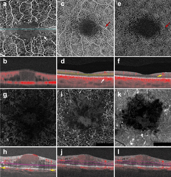
OCTA Artifacts. a, b Motion artifact: en face image of the full retinal projection, white arrow points to an example of motion artifact (a). The horizontal lines represent areas where OCTA acquisition was disrupted by movement. B-scan through this area (b) shows a blurry image with erroneous flow pixels. c–f Projection artifact: en face projection of the ddeep retinal layer before artifact removal c and after artifact removal e. Red arrows point to a projected vessel from the superficial retinal layer, note that the same vessel is no longer present after software correction. Corresponding B-scans (d, f) show a superficial retinal vessel reflected on the RPE (white arrow) and a decorrelation tail trailing below the vessel (yellow arrow). g, h Segmentation error: en face projection of the choriocapillaris in a patient with diabetic macular edema. At first glance, lack of flow pixels suggests widespread non-perfusion (g), however, B-scan reveals a significant segmentation error due to edema (h). Yellow arrows point to correct choriocapillaris segmentation level. i–l Shadowing: en face projection of the deep capillary plexus suggests central vascular loss (I). Corresponding structural en face image shows reduced signal in this area (k). Accompanying B-scan reveals signal attenuation is secondary to overlying edema, not vascular loss (j, l)
Full size image
Many device manufacturers rely on two types of technology to correct for motion artifact: mechanical eye tracking and software motion correction [1]. Eye tracking measures the position of the eye and corrects for eye movement when the change in eye position exceeds a predetermined threshold. Devices can rescan the area of detected motion and incorporate it into the original image [23]. Software motion correction obtains a horizontal and a vertical raster scan [24]. The software interprets the two scans together to calculate displacement between A-scans and corrects for motion in the final image. Today, most devices combine both technologies to produce high quality images.
Shadowing artifact
Shadowing occurs when the OCT beam is blocked and cannot reach the outer retinal layers. Many pathological features cause shadowing including drusen, hemorrhage and vitreous floaters [17]. Light is reflected off of these structural aberrations and does not penetrate the underlying tissue. Areas below these features appear as flow voids because the OCT beam cannot adequately assess them (Fig. 1g–j). The longer wavelength of SS-OCTA systems makes them less prone to shadowing than their spectral domain counterparts. SS-OCTA devices can assess the outer retinal layers below these features, though some signal attenuation persists. Recently, several groups have published algorithms that combine structural and angiography data to compensate for shadowing artifact below drusen [25, 26]. Though this technology is not currently available on commercial OCTA devices, this research shows promise and similar algorithms could be incorporated into future software updates.
Projection artifacts
Projection artifacts, or decorrelation tails, are perhaps the most prominent and important artifacts seen on OCTA. As the OCT beam penetrates the retina, it first encounters the superficial capillary plexus. A portion of light is reflected back from this plexus and interpreted by the device. Light that is not reflected continues to travel through the retina until it reaches the RPE. The RPE acts a natural reflector, reflecting light back towards the OCTA device. Light that arrives at the RPE is influenced by the flow above it and generates a decorrelation signal that mimics superficial vascular beds. The result is the erroneous appearance of superficial vessels in the outer retina and RPE (Fig. 1c, d). This misinterpretation of flow is termed projection artifact.
Device manufacturers have engineered many ways to overcome projection artifacts (Fig. 1e). The first form of projection artifact removal (PAR), slab-subtraction, subtracted inner retinal vascular patterns from outer retinal slabs [27]. Though this algorithm succeeded in reducing projection artifact, it also led to signal loss in the outer retinal layers. Further, slab-subtraction depended on pre-determined slab selection and did not successfully suppress projection artifacts on B-scan. In 2016, Zhang and colleagues published a projection-resolved PAR algorithm. Unlike slab-subtraction, this new algorithm worked on a voxel-by-voxel basis, utilizing intensity-normalized decorrelation values to distinguish in situ flow from projection artifact. This algorithm successfully identified the presence of multiple in situ vessels along an axial scan and did not suppress flow signal in the outer retina. Such improvements allowed for the visualization of three distinct retinal vascular plexi on en face and B-scan [28]. More recently, Garrity et al. proposed a three-dimensional PAR algorithm. Similar to the projection-resolved technique described by Zhang’s group, this new algorithm determines in situ flow by assessing intensity-normalized decorrelation signals on a voxel-by-voxel basis. However, the three-dimensional model incorporates signal intensity information along the Z-axis, assessing OCTA signal in all directions around a single voxel prior to determining if true flow is present [29, 30].
Though technological innovation has greatly improved PAR, compensation methods are not perfect, nor are they uniformly available across OCTA devices. When interpreting OCTA images, the easiest way to detect projection artifacts is to compare en face flow with the corresponding B-scan. On B-scan, projections artifacts appear as “tails” arising from overlying vessels and should not be interpreted as true flow (Fig. 1f).
Segmentation artifacts
The review software on commercially available devices provides a series of retinal slabs for analysis (i.e. full retinal, superficial retina, choriocapillaris, choroid). Each slab is generated by selecting an upper and lower boundary that slices horizontally through the three-dimensional OCTA cube. The vessels that lie within these two boundaries are projected to produce an en face image. Algorithms automatically detect predetermined retinal boundaries based on distinguishing characteristics such as reflectivity and texture [1]. However, segmentation algorithms were developed by imaging healthy eyes with distinct retinal layers [31]. Disease pathology, such as fluid seen in DME, drusen in AMD and even myopia, can drastically alter retinal anatomy and cause algorithms to mislabel boundaries (Fig. 1g, h). In such cases, assessing segmentation on the B-scan can reveal the error.
There are two ways to manipulate segmentation boundaries in order to correct for segmentation errors: slab selection and manual segmentation. Slab selection is simple and involves dragging a preset boundary up and down the z-axis. This action generates larger or smaller slabs to better assess pathology of interest (i.e. type 2 macular neovascularization in wet AMD). Manual segmentation allows the user to retrace the mislabeled retinal layer (i.e. Bruch’s membrane in a patient with drusen). Proper retracing must be completed for each B-scan which is a time consuming and laborious process. This type of boundary correction is largely reserved for research purposes, as it lacks utility in the time constraints of clinical practice.
OCTA interpretation: basic toolkit
To ensure correct interpretation, the three-dimensional quality of OCTA imaging must be respected. Viewing two-dimensional OCTA representations without simultaneously interacting with the three-dimensional dataset can confound interpretation. As a general rule, three images must be concurrently assessed for accurate OCTA interpretation: the en face OCTA image; the corresponding B-scan with flow overlay and segmentation lines displayed; and the structural en face intensity image for the selected slab. Assessing all three image components at once reduces erroneous findings.
The following section describes a step-by-step approach to OCTA interpretation (Fig. 2). The steps described can be applied to any device and to any type of ocular pathology. The model provides a foundation for OCTA interpretation and helps users avoid common mistakes.
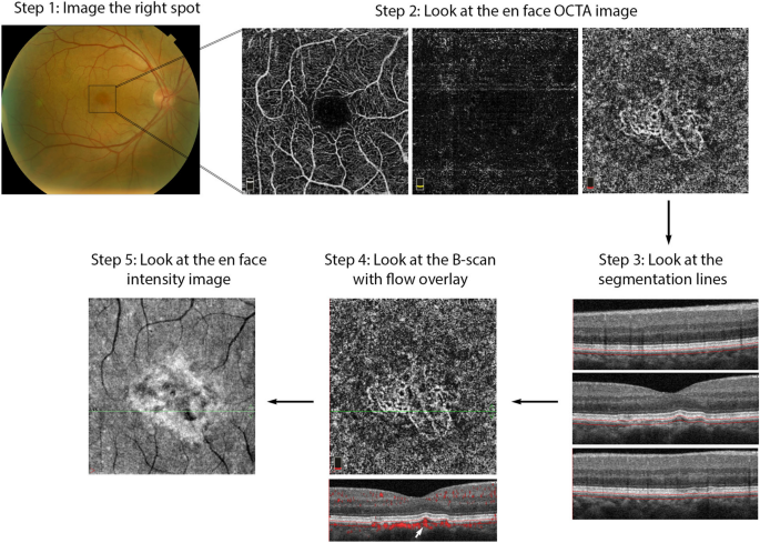
OCTA Interpretation Toolkit. How to apply step-by-step OCTA interpretation toolkit in a patient with AMD. Step 1: Image the right spot. Color fundus photograph of a patient with known AMD, the macula was selected as the area of interest and imaged. Step 2: Look at the en face OCTA images. 3 × 3 mm en face projections of each the full retinal depth, the avascular slab and the choriocapillaris (from left to right). The avascular and choriocapillaris slabs should be assessed in this AMD patient to check for presence of MNV. Note clearly defined vascular structures in the choriocapillaris slab (right most image), this is concerning for a type 1 MNV. Step 3: Look at the segmentation lines. Segmentation is assessed at multiple points throughout the slab to ensure accuracy. Step 4: Look at the B—scan with flow overlay. B-scan through lesion shows clear flow below the RPE (white arrow) and no projection artifact from overlying vasculature, suggesting this is in fact an MNV. Step 5: Look at the en face intensity image. En face intensity image for the choriocapillaris slab shows strong signal, shadowing artifact is not expected to disrupt image interpretation. Summary: Methodical OCTA image analysis uncovered a type 1 MNV that was not visible on fundus examination or on full depth retinal projection
Full size image
Step 1: image the correct spot
The first step in proper OCTA interpretation is to ensure the right location in the posterior retina is imaged. OCTA devices offer a range of scan sizes that can be centered at the macula and, in a subset of devices, the optic nerve head. To increase the scanning area, manufacturers developed montage options that stitch multiple scans together into a single image. Though montage images display a large portion of the posterior retina, the repeated imaging they require is time consuming and can be tiring for patients. Given decreased resolution in larger scan sizes, it is preferable to select the smallest scan size possible to visualize the pathology of interest. For instance, a small MNV can be visualized with greatest detail in a 3 × 3 mm scan. However, in a patient with DR, a larger scan size might be more appropriate for the assessment of proliferative diabetic retinopathy (PDR) and neovascularization elsewhere (NVE).
When the macular scan does not capture desired pathology, internal fixation targets can be moved to visualize different sectors of the posterior pole. For example, in the case of choroidal hemangiomas, lesions often occur far from the macula and might be missed by a macular scan [32]. Moving internal fixation targets, and employing external fixation targets when necessary, can help imaging technicians capture more peripheral lesions. For OCTA imaging to be effective, the clinician should first highlight what area of the posterior retina contains the pathology of interest. This ensures the technician will image the right location, allowing full visualization of desired pathology.
Step 2: look at the en face OCTA image
En face OCTA images provide a valuable overview of the retinal vasculature. These images can display a vascular projection of the full retinal depth or separate projections of each the superficial capillary plexus, the deep capillary plexus, the avascular retina, the choriocapillaris and the choroid.
The automated superficial retinal slab in most devices spans the internal limiting membrane, the ganglion cell layer and the inner plexiform layer (Fig. 3a). This slab captures the superficial capillary plexus of the retina and, often, part of the radial peripapillary capillary plexus. It also delineates the foveal avascular zone. This slab is important in retinal vascular diseases where drop out or malformation of the microvasculature can be seen. In DR, for example, enlargement of the foveal avascular zone, capillary drop out, and microaneurysms are best visualized on this slab. Additionally, some devices allow for quantitative evaluation of the vessels in this slab including vessel density and foveal avascular zone area.

OCTA slabs and corresponding segmentation boundaries. a Superficial retinal slab. This slab displays information for the internal limiting membrane, the ganglion cell layer and the inner plexiform layer. It is useful for FAZ area delineation in diabetic retinopathy. b Deep retinal slab. This slab displays information for the inner nuclear layer and the outer plexiform layer. Projection artifact removal was used to block signal from the superficial capillary plexus on this en face image. This slab may show the first signs of vascular loss in diabetic retinopathy. c Avascular slab. This slab displays information for the outer plexiform layer and the outer nuclear layer. Note that despite projection artifact removal remnants of overlying vessels are noted in this image. d Choriocapillaris slab. Along with the avascular slab, the choriocapillaris slab is important for detection of macular neovascularization in AMD. e Outer retinal choriocapillaris slab. This slab displays information for the outer plexiform layer, the outer nuclear layer and the choriocapillaris. It is useful as a screening tool for all types of macular neovascularization in AMD. f Choroid slab. Clear choroidal vessels are not visualized due to signal blockade from the RPE and overlying retinal layers
Full size image
On most devices, the deep retinal slab spans the inner nuclear layer and the outer plexiform layer and includes the intermediate and deep capillary plexuses (Fig. 3b). OCTA is the only clinically available commercial imaging modality that can visualize these two capillary plexuses in vivo [1]. Studies have shown that the deep capillary plexus is not visible on FA due to its intraretinal depth and the small size of its vessels [29]. The deep capillary plexus may be one of the first vascular beds to be affected in patients with retinal vascular diseases such as diabetes [33, 34]. In fact, OCTA studies of the deep capillary plexus have shown early changes associated with DR pathophysiology [34]. However, analysis of the deep retinal plexus must be conducted with care, as the presence of projection artifacts from the superficial plexus and the software used to remove these artifacts can often confound interpretation.
The avascular or outer retina slab spans the outer plexiform layer and the outer nuclear layer. This slab is avascular in healthy individuals (Fig. 3c). The presence of vessels in this layer is usually an indicator of pathology. For example, in patients with wet AMD the avascular layer may show type 2 or type 3 macular neovascularization (MNV). Though this layer should always be evaluated in patients with suspected AMD, it is prone to segmentation errors caused by outer retinal pathology such as a pigment epithelial detachments (PEDs).
The choriocapillaris slab is defined as a 20-micron slab below the RPE (Fig. 3d). Much like the avascular slab, the choriocapillaris slab should be evaluated in AMD and other pathologies associated with MNV formation. The choriocapillaris slab will not show distinct vascular channels. Instead, flow is represented on a pixel-by-pixel basis with hyper-reflective spots representing flow in this vascular layer. Presence of well-formed vascular channels in this slab (especially between Bruch’s membrane and the RPE) are very suspicious for choroidal neovascularization, specifically for type 1 MNV.
Due to the utility of the avascular and choriocapillaris slabs for MNV detection, some instruments display a combination of both slabs, known as the outer retinal and choriocapillaris (ORCC) slab (Fig. 3e). First described by Rosenfeld et al., this slab spans the outer plexiform layer, the outer nuclear layer and the choriocapillaris and can be used as a screening slab for type 1, 2 or 3 MNVs [13].
Lastly, the choroid slab displays a 50-micron slice posterior to the choriocapillaris (Fig. 3f). Differences in wavelength and light source lead to variable detection of choroidal vasculature between devices. Advances in laser technology allow for deeper penetration and visualization of choroidal vessels in investigative prototype models [35]. Though this technology is not yet commercially available, future device iterations might improve choroidal visualization and provide insight into pathologic changes occurring in this vascular layer.
Step 3: look at the segmentation lines
Pre-set slabs in OCTA devices are generated by automated segmentation. Retinal layer detection is remarkably accurate in healthy eyes, but can be distorted in the presence of retinal pathology [31]. Once a slab is selected for interpretation, it is important to assess the segmentation lines that define it to ensure correct identification of retinal boundaries. Improper slab placement can lead to pathology being missed or to the mislabeling of normal vasculature as pathologic. For instance, in AMD, inaccurate slab selection might cause an MNV to be missed or, contrastingly, it might cause a PED to be confused for an MNV. If pathology has in fact distorted the software’s ability to detect retinal layers, retinal slab selection can be coarsely adjusted by dragging the slab boundaries up or down.
Step 4: look at the B-scan with flow overlay
OCTA displays a two-dimensional projection of a three-dimensional structure, the retina. En face images should, therefore, always be interpreted in the context of their corresponding B-scan. For instance, en face projection can erroneously depict two vessels traveling at different retinal depths as a single branching vessel. Simultaneous assessment of the B-scan cross section provides a depth reference for the vasculature seen on en face and can help discern these optical illusions. Moreover, B-scan analysis can uncover projection artifacts. When assessing flow in the outer retinal layers, B-scan images can distinguish true flow from decorrelation tails produced by overlying vasculature. B-scans are critical when assessing pathology because they can help correlate vasculature to pathologic structural changes. For example, identification of flow between the RPE and the Bruch’s membrane in the presence of a PED gives a high level of confidence for the presence of a type 1 MNV (Figs. 2, 9).
Step 5: look at the en face intensity image
If light penetration through the retina is obfuscated by overlying pathology, such as fluid, hemorrhage or drusen, flow cannot be adequately assessed. The presence of these pathologic features reduces the signal produced by underlying retinal layers. As explained earlier, this reduction in signal is termed shadowing and can be misinterpreted as reduced flow.
Assessing the en face intensity image in concert with the OCT angiogram can help determine if loss of flow is real, or mere shadowing from overlying pathology. The structural and angiography projection for a given retinal slab should be examined in concert. If the structural en face image shows good signal intensity and the angiogram shows reduced flow in the same area, this can be interpreted as a true reduction in flow. If the structural en face image shows low signal intensity and the angiogram shows reduced flow in the same area, shadowing artifact is likely (Fig. 4).
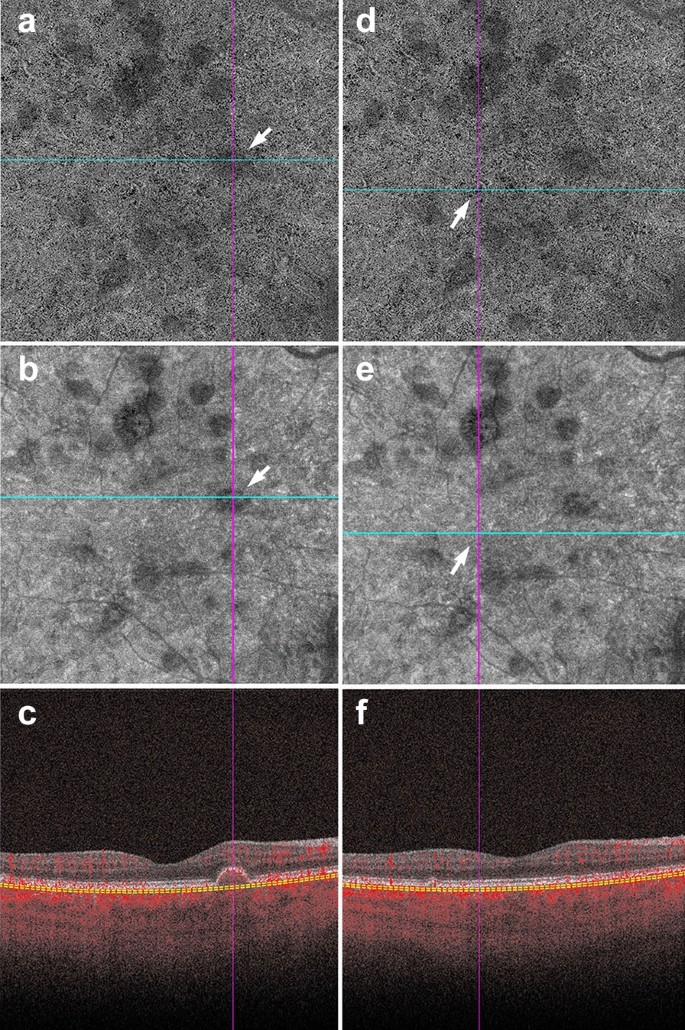
Shadowing in AMD. a–f Signal attenuation from drusen can be misinterpreted as non-perfusion in the choriocapillaris. Careful examination of the corresponding structural OCTA scan can rectify this error. a, d 6 x 6 mm choriocapillaris slab of a patient with AMD. a White arrow points to an area of apparent flow reduction. b Corresponding structural choriocapillaris slab. White arrow shows that the same area has reduced signal intensity. c B-scan shows a druse at this location. Signal reduction in this area should not be interpreted as non-perfusion, as it is likely due to signal attenuation and not flow reduction. d Identical choriocapillaris slab as that shown in panel A. White arrow points to an area of apparent flow reduction. e Corresponding structural choriocapillaris slab shows that this area has appropriate signal intensity (white arrow). f B-scan shows no druse or underlying pathology in this area. Signal reduction in this area can be appropriately interpreted as choriocapillaris loss
Full size image
Conversely, the presence of atrophy causes RPE disruption and increased signal penetration into the choroid. En face structural images will show increased signal intensity over atrophic areas. Accompanying choriocapillaris loss leads to upward displacement of the larger choroidal vasculature, which can mimic a MNV on OCTA en face (Fig. 5a). In this situation, evaluation of the B-Scan cross section will show choroidal flow and light hypertransmission associated with atrophy (Fig. 5d) [36].
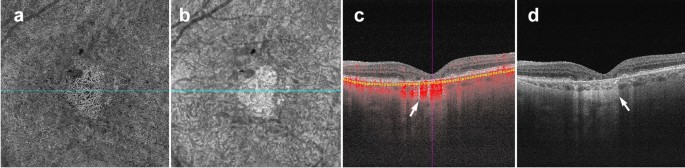
Choroidal vessels below atrophic areas. a–d Images of a patient with advanced AMD and geographic atrophy. Atrophy causes RPE and choriocapillaris disruption. a En face choriocapillaris angiogram shows displaced choroidal vessels mimicking well-formed vessels seen in macular neovascularization. b En face choriocapillaris structural image shows increased signal intensity in atrophic area due to RPE disruption and increased signal penetration into the choroid. c B-scan through atrophic area shows increased choroidal flow detection and upward displacement of choroidal vasculature below the atrophic area (white arrow). d B-scan without flow overlay shows choroidal hypertransmission (white arrow), a known OCT landmark for geographic atrophy
Full size image
Clinical utility of OCTA in retinal pathology
The above interpretation toolkit provides a foundation for OCTA image analysis. Understanding what OCTA features to focus on for specific disease entities can reduce interpretation times and prevent interpretation errors.
OCTA in diabetic retinopathy
FA studies conducted by the ETDRS group and others identified vascular changes associated with DR long ago [37,38,39]. OCTA research reproduced these findings and furthered our understanding of the vascular changes in DR [40]. Studies comparing FA to histology reveal that FA can only visualize a fraction of the retinal vasculature [41]. This suggests that FA lacks the sensitivity to detect vascular losses seen in the early stages of DR [10]. OCTA provides high resolution images of the retinal capillary beds, and can identify early vascular changes associated with DR that FA missed. In fact, recent studies show OCTA can identify vascular changes in diabetic patients without signs of retinopathy [42, 43]. These studies suggest the potential of OCTA as a screening tool for diabetic patients.
Aside from its promise in identifying early changes in diabetic eyes, OCTA can be used as a follow-up tool for patients with DR. Currently, FA is considered the gold standard for vessel visualization in DR [44]. However, FA is time consuming and invasive, making it difficult to obtain at every patient visit. OCTA is a fast and safe way to follow vascular changes in patients with DR. Much research has been done in the field of DR and OCTA, however, there are three main findings of particular relevance to clinical practice: foveal avascular zone (FAZ) enlargement, detection of microaneurysms, and vascular changes.
FAZ enlargement
Early FA studies show that FAZ area increases with DR severity [45]. OCTA studies have replicated these findings in the full retinal layer, the superficial capillary plexus and the deep capillary plexus [46, 47]. FAZ area is considered to be a reliable and reproducible metric between readers in both normal eyes and eyes with DR [48, 49]. Though FAZ can be assessed at both the deep capillary plexus and superficial capillary plexus, there is evidence to suggest that the retinal plexuses meet at the edge of the FAZ and it is, therefore, preferable to measure the FAZ on the superficial or the full retinal depth projection [50]. Assessing FAZ area on the full retinal depth projection obviates the need for segmentation and accompanying errors, increasing the measurement’s reproducibility [51, 52]. Clinically, assessing FAZ enlargement over time can be a useful tool for following DR progression (Fig. 6).
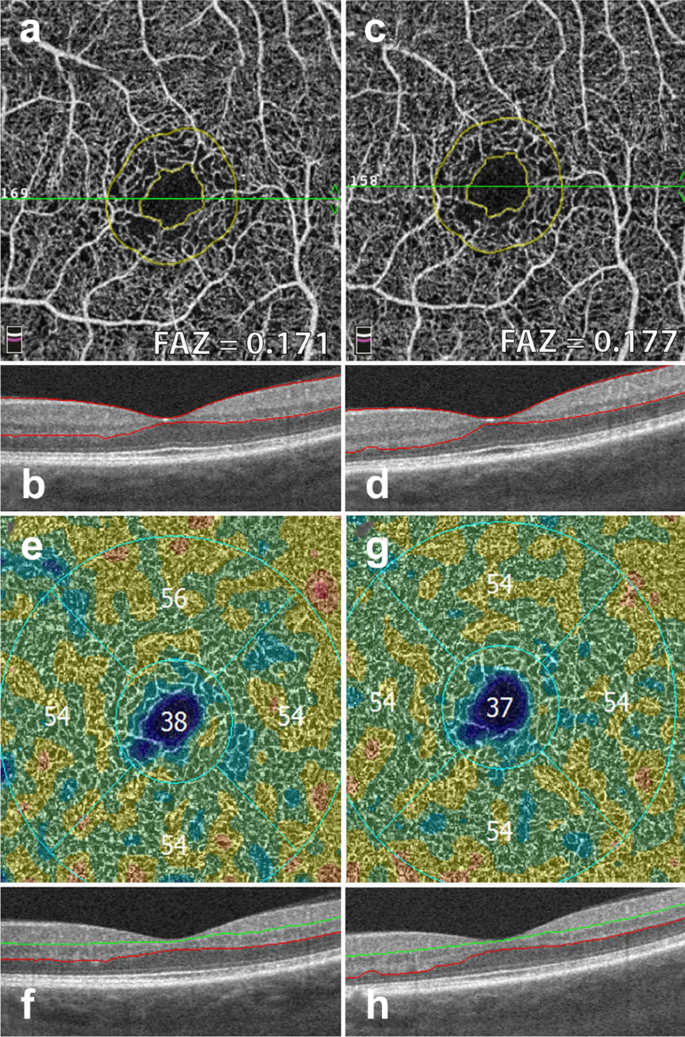
FAZ area and vessel density measurements. Example of a patient with severe non proliferative diabetic retinopathy. Images in the left column were taken 12 months prior to images in the right column. a, c Superficial retinal slab projection showing automated FAZ area measurements. Note parafoveal capillary drop out and slight increase in FAZ area over time. b, d B-scan showing corresponding segmentation boundaries. e, f Vessel density map of the deep retinal slab for the same patient and timepoints. Note slight drop in vessel density in the superior quadrant. f, g B-scan with corresponding segmentation lines
Full size image
Microaneurysms
Microaneurysms (MA) are a landmark finding in DR and are associated with an increased risk of progression to advanced disease stages [39, 53]. Studies show that OCTA can visualize approximately 60% of the MA identified on FA [46, 54]. MA are focal dilations of retinal capillaries. Flow can slow within these capillary dilations and drop below the OCTA detection threshold [1]. Prior to the advent of anti-VEGF agents, identifying the location of all MA was essential to proper laser treatment. As anti-VEGFs are increasingly used to treat complications of DR, including DME and PDR, OCTA can be used to track the response of MA to treatment (Fig. 7) [55, 56]. Though MA tracking has little utility in assessing treatment response in DME, the presence of increased MAs and ischemia may mark areas at higher risk of DME recurrence [57].
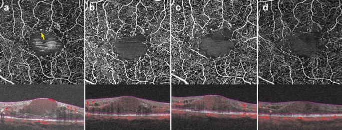
Microaneurysm response to anti-VEGF therapy. a–d 3 x 3 mm images of the full retinal depth projection of a patient treated with anti-VEGF therapy for diabetic macular edema. Images were taken 3 months apart over a 10-month period. a Yellow arrow points to an example of a microaneurysm. Note reduction in the number of parafoveal microaneurysms over time with concurrent improvement of edema
Full size image
Vascular changes
Research has uncovered associations between vascular changes seen on OCTA and increasing DR severity [58]. Studies point to significant vessel loss in patients with DR as compared to healthy controls [59]. A negative association between vessel density and increasing DR severity at both the superficial and deep capillary plexuses has been repeatedly identified [60,61,62]. Though quantitative vessel metrics on OCTA have been shown to have low reproducibility between devices, certain OCTA platforms provide color coded perfusion maps based on the vessel density of normal eyes [52]. These maps can help providers track DR severity and assess vessel loss in conjunction to disease progression (Fig. 6) [3].
In addition to the vascular changes associated with non-proliferative DR, OCTA is also useful in the clinical management of PDR. PDR is an advanced stage of DR that can lead to vision threatening complications such as hemorrhage and tractional retinal detachment [63]. Neovascular changes associated with PDR can been visualized on OCTA (Fig.  [2]. OCTA can identify neovascular growth and follow its regression in response to anti-VEGF treatment [64].
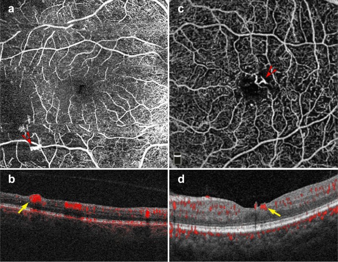
Proliferative diabetic retinopathy. a–d 6 x 6 mm images of the full retinal depth projection of two patients with proliferative diabetic retinopathy (PDR). a, c En face view of PDR, red arrowheads point to areas of neovascularization. b, d Corresponding B-scans show flow at the vitreoretinal interface (yellow arrows)
Full size image
Widefield OCTA imaging
Though original OCTA devices imaged only the central macula, newer OCTA technology offers a wider field of view. New swept source devices have larger scan areas of 15 × 9 mm and 12 × 12 mm and can visualize a greater portion of the posterior retina when compared to original devices offering only 3 × 3 and 6 x 6 mm scans [65]. As the field of view expands, however, resolution decreases and acquisition times lengthen. To offset resolution loss, montage protocols that offer fields of view of up to 100 degrees without sacrificing resolution have been developed. Though the 100-degree field of view offered by wide-angle OCTA is smaller than the 200-degree field of view offered by ultra-wide field (UWF) FA, OCTA images display higher levels of vascular detail and offer three-dimensional data not available on FA [66].
An increased field of view allows for improved imaging of the posterior pole, an important characteristic when assessing peripheral DR pathology. Wide-field SS-OCTA can be utilized to detect PDR and track response to panretinal photocoagulation. When compared to UWF FA, wide-field SS-OCTA was equivalent for the identification of PDR progression and regression, but SS-OCTA offered more detailed visualization of vascular changes [67]. Studies comparing UWF FA and wide-angle OCTA have found both imaging modalities equivalent for the detection of capillary drop out and retinal neovascularization in DR [68, 69]. These findings are encouraging and suggest wide-angle OCTA may provide a non-invasive alternative for vascular monitoring in DR.
OCTA in AMD and MNV
OCTA has proven invaluable for the study of AMD. The ability of OCTA to visualize the choriocapillaris in intermediate AMD and later stages of the disease has shed light onto the etiology of this vision threatening disease. Though OCTA has provided great investigative insight into the changes underlying dry AMD, the clinical use of OCTA in AMD is largely limited to the diagnosis of neovascular or wet AMD. Based on structural OCT, there are three types of MNV associated with wet AMD. Type 1 MNV lies below the RPE, type 2 MNV lies between the RPE and the retina, and type 3 MNV arises from the superficial retinal vasculature and grows downwards toward the neurosensory retina and eventually the choriocapillaris [70].
The ability to register flow information with structure makes OCTA a useful tool for MNV diagnosis and classification. En face OCTA images can depict the vascular networks associated with each type of MNV, while B-scans reveal their exact location within the retina (Fig. 9). OCTA can detect non-exudative MNV that were previously unnoticed. These lesions are generally type 1 MNV that lie below the RPE and are associated with a ‘double layer sign’, flat irregular, low lying PEDs that may go unnoticed in a superficial evaluation of OCT scans [71]. Studies suggest high sensitivities and specificities for the identification of type 1 and type 2 MNV on OCTA [72, 73]. However, MNV detection sensitivity drops precipitously with signal reduction secondary to hemorrhage and large PEDs, so OCTA should be used with caution in this context [74].
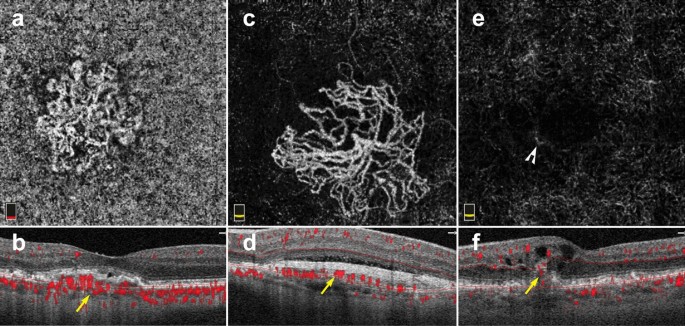
Macular neovascularization types. a–f 3 x 3 mm en face images and corresponding B-scans for the 3 MNV types seen in wet AMD. Segmentation was manually adjusted to reveal the best en face view for each lesion. a,b Type 1 MNV: distinct vascular inlets at the level of the choriocapillaris are seen on en face (a), B-scan reveals flow below the RPE (b, yellow arrow). c, d Type 2 MNV: en face view shows vascular branching suspicious for an MNV (c), B-scan shows flow between the retina and the RPE (d, yellow arrow). e, f Type 3 MNV: en face view shows a small bright tuft (e, white arrowhead), B-scan view shows intraretinal flow trailing downwards, towards the choriocapillaris (f, yellow arrow). Of note, type 3 MNV are very difficult to visualize on en face and often appear only as small, white tufts as depicted in the above example (e)
Full size image
Visualization of MNV on OCTA is helpful for diagnosis and classification. However, the clinical utility of OCTA for tracking MNV response to anti-VEGF treatment remains unclear. Several studies reveal MNV shrinking on OCTA after anti-VEGF treatment, albeit often without complete resolution [75,76,77,78]. A study by Lumbroso and colleagues showed that MNV reach maximal size reduction 1 week after intravitreal anti-VEGF injection, and progressively increase in size thereafter. Interestingly, this work also showed that MNV expansion predates MNV re-exudation [79]. Tracking MNV changes on OCTA to assess treatment response has not been proven to improve clinical outcomes. Thus, decisions regarding re-treatment are currently driven by visual acuity, clinical examination, presence of exudation and structural OCT changes.
Interpretation pitfalls discussed earlier in this review must be carefully considered when studying AMD and MNV on OCTA. Important points to remember include:
-
(1)
AMD features, such as drusen, geographic atrophy and MNV, can affect automatic device segmentation. Assessment of segmentation lines on B-scan is necessary prior to interpretation.
-
(2)
MNV lesions should always be interpreted in the context of their corresponding B scan. MNV types lie at different retinal depths. The preset slabs available on commercial OCTA devices often do not provide an ideal en face view of MNV lesions. Instead, manual slab selection can be used to fully encompass the lesion and improve en face visualization of MNV vessel networks.
-
(3)
Reflective surfaces such as the RPE above type 1 MNV and drusen can lead to projection of flow from overlying retinal vasculature. B-scan assessment can help highlight this type of artifact and reduce false-positive findings.
OCTA and other pathologies
The use of OCTA in clinical practice is not limited to DR and AMD. OCTA is useful in a range of retinal pathology including retinal vascular disease, retinal inflammatory disease, retinal tumors and retinal hereditary dystrophies.
In venous occlusive diseases, such as central and branch retinal vein occlusions, OCTA can identify areas of non-perfusion as well as collateral vessel formation [80, 81]. Manual slab selection provides information regarding the affected retinal vascular layers and the location of new collateral vessels. In retinal inflammatory disease, OCTA can detect vascular changes associated with inflammation including retinal hypo-perfusion in occlusive vasculitis and increased vessel density around the optic nerve head in uveitis [8, 82]. Moreover, OCTA aids in the identification of choroidal neovascularization secondary to inflammation (iCNV). Since inflammatory CNVs can mimic other types of inflammatory non-neovascular lesions, OCTA can detect flow within iCNVs and lead to prompt diagnosis and treatment [83].
OCTA has led to novel vascular findings in retinal hereditary dystrophies. For example, patients with choroidemia have reduced macular choriocapillaris density on OCTA when compared to controls, a finding not previously recognized by standard angiography [84]. OCTA was found to be superior to FA for the detection of CNV in patients with Best Vitelliform Macular Dystrophy, due to improved signal penetration through vitelliform material [85]. The use of OCTA for the vascular assessment of ocular tumors has also been extensively studied [86]. Vascular findings on OCTA, such as avascular areas and vascular abnormalities, might be of clinical utility in the differentiation of choroidal nevi from small choroidal melanomas [87]. In retinal capillary hemangioblastomas, OCTA can be used for diagnosis and assessment of treatment response to anti-VEGF therapy [88].
The future of OCTA
OCTA is evolving from a research tool to a clinically useful imaging modality. Its ease of use, depth resolution, and ability to analyze microvasculature provide a wealth of information beyond what other retinal vascular imaging offers.
The advent of swept source OCTA technology allowed for clear visualization of choroidal vasculature [15]. As laser technology continues to improve, newer devices with increased signal penetration will visualize choroidal vascular detail at greater depths. Further, faster scanning speeds will allow for wider and wider fields of view. This could have lasting implications for the assessment and risk stratification of a host of diseases from choroidal tumors and choroidal neovascularization, to retinal vascular disease.
Along with these hardware improvements, technical innovations in OCTA signal processing have reduced the presence of artifacts in prototype devices [28]. Device implementation of image alignment and tracking for longitudinal data will better serial assessment of progressive retinal diseases, including AMD and DR. As these improvements become commercially available, the clinical applicability and utility of OCTA will continue to expand and could have lasting implications in the way we image the retinal vasculature. Moreover, application of machine learning to OCTA will yield insights into new pathologic signals that were previously overlooked that could greatly impact the clinical management of retinal disease [89, 90].
The future of OCTA is promising, but clinicians require appropriate training to derive meaning out OCTA data and to avoid interpretation errors. This review provides eye care professionals with a toolkit for OCTA interpretation in the clinical setting. A solid understanding of the artifacts associated with OCTA imaging along with a step-wise approach to image interpretation offers the flexibility to apply OCTA analysis to a wide range of ocular pathology.
Availability of data and materials
Not applicable.
Abbreviations
- OCTA:
-
Optical coherence tomography angiography
- FA:
-
Fluorescein angiography
- ICGA:
-
Indocyanine green angiography
- AMD:
-
Age-related macular degeneration
- DR:
-
Diabetic retinopathy
- OCT:
-
Optical coherence tomography
- SD-OCT:
-
Spectral domain optical coherence tomography
- SD-OCTA:
-
Spectral domain optical coherence tomography angiography
- SS-OCTA:
-
Swept source optical coherence tomography angiography
- Anti-VEGF:
-
Vascular endothelial growth factor antagonists
- RPE:
-
Retinal pigment epithelium
- DME:
-
Diabetic macular edema
- MNV:
-
Macular neovascularization
- ORCC:
-
Outer retinal and choriocapillaris
- PED:
-
Pigment epithelial detachment
- FAZ:
-
Foveal avascular zone
- MA:
-
Microaneurysm
- PDR:
-
Proliferative diabetic retinopathy
- CNV:
-
Choroidal neovascularization
References
-
Spaide RF, Fujimoto JG, Waheed NK, Sadda SR, Staurenghi G. Optical coherence tomography angiography. Prog Retin Eye Res. 2018;64:1–55.
Article
PubMedGoogle Scholar
-
Choi W, Waheed NK, Moult EM, et al. Ultra high speed swept source optical coherence tomography angiography of retinal and choriocapillaris alterations in diabetic patients with and without retinopathy. Retina. 2017;37:11–21.
Article
CAS
PubMed
PubMed CentralGoogle Scholar
-
Agemy SA, Scripsema NK, Shah CM, et al. Retinal vascular perfusion density mapping using optical coherence tomography angiography in normals and diabetic retinopathy patients. Retina. 2015;35:2353–63.
Article
PubMedGoogle Scholar
-
Palejwala NV, Jia Y, Gao SS, et al. Detection of nonexudative choroidal neovascularization in age-related macular degeneration with optical coherence tomography angiography. Retina. 2015;35:2204–11.
Article
PubMed
PubMed CentralGoogle Scholar
-
Moult EM, Waheed NK, Novais EA, et al. Swept-source optical coherence tomography angiography reveals choriocapillaris alterations in eyes with nascent geographic atrophy and drusen-associated geographic atrophy. Retina. 2016;36(Suppl 1):S2–s11.
Article
PubMed
PubMed CentralGoogle Scholar
-
Iafe NA, Phasukkijwatana N, Sarraf D. Optical coherence tomography angiography of Type 1 neovascularization in age-related macular degeneration. Dev Ophthalmol. 2016;56:45–51.
Article
PubMedGoogle Scholar
-
Kim AY, Rodger DC, Shahidzadeh A, et al. Quantifying retinal microvascular changes in uveitis using spectral-domain optical coherence tomography angiography. Am J Ophthalmol. 2016;171:101–12.
Article
PubMed
PubMed CentralGoogle Scholar
-
Rougier MB, Le Goff M, Korobelnik JF. Optical coherence tomography angiography at the acute phase of optic disc edema. Eye Vis. 2018;5:15.
Article
Google Scholar
-
Huang D, Swanson EA, Lin CP, et al. Optical coherence tomography. Science. 1991;254:1178–81.
Article
CAS
PubMed
PubMed CentralGoogle Scholar
-
Kashani AH, Chen C-L, Gahm JK, et al. Optical coherence tomography angiography: a comprehensive review of current methods and clinical applications. Prog Retinal Eye Res. 2017;60:66–100.
Article
Google Scholar
-
Choi W, Moult EM, Waheed NK, et al. Ultrahigh-speed, swept-source optical coherence tomography angiography in nonexudative age-related macular degeneration with geographic atrophy. Ophthalmology. 2015;122:2532–44.
Article
PubMedGoogle Scholar
-
Ploner SB, Moult EM, Choi W, et al. Toward quantitative optical coherence tomography angiography: visualizing blood flow speeds in ocular pathology using variable interscan time analysis. Retina. 2016;36(Suppl 1):S118–s126.
Article
PubMed
PubMed CentralGoogle Scholar
-
Miller AR, Roisman L, Zhang Q, et al. Comparison between spectral-domain and swept-source optical coherence tomography angiographic imaging of choroidal neovascularization. Invest Ophthalmol Vis Sci. 2017;58:1499–505.
Article
PubMed
PubMed CentralGoogle Scholar
-
Lane M, Moult EM, Novais EA, et al. Visualizing the choriocapillaris under Drusen: comparing 1050-nm swept-source versus 840-nm spectral-domain optical coherence tomography angiography. Invest Ophthalmol Vis Sci. 2016;57:585–90.
Article
Google Scholar
-
Novais EA, Adhi M, Moult EM, et al. Choroidal neovascularization analyzed on ultrahigh-speed swept-source optical coherence tomography angiography compared to spectral-domain optical coherence tomography angiography. Am J Ophthalmol. 2016;164:80–8.
Article
PubMed
PubMed CentralGoogle Scholar
-
Matsunaga D, Yi J, Puliafito CA, Kashani AH. OCT angiography in healthy human subjects. Ophthalmic Surg Lasers Imaging Retina. 2014;45:510–5.
Article
PubMedGoogle Scholar
-
Borrelli E, Sarraf D, Freund KB, Sadda SR. OCT angiography and evaluation of the choroid and choroidal vascular disorders. Prog Retin Eye Res. 2018;67:30–55.
Article
PubMedGoogle Scholar
-
Kwiterovich KA, Maguire MG, Murphy RP, et al. Frequency of adverse systemic reactions after fluorescein angiography. Results of a prospective study. Ophthalmology. 1991;98:1139–42.
Article
CAS
PubMedGoogle Scholar
-
Kashani AH, Lee SY, Moshfeghi A, Durbin MK, Puliafito CA. Optical coherence tomogrpahy angiography of retinal venous occlusion. Retina. 2015;35:2323–31.
Article
PubMedGoogle Scholar
-
Hwang TS, Jia Y, Gao SS, et al. Optical coherence tomography angiography features of diabetic retinopathy. Retina. 2015;35:2371–6.
Article
PubMed
PubMed CentralGoogle Scholar
-
Moult E, Choi W, Waheed NK, et al. Ultrahigh-speed swept-source OCT angiography in exudative AMD. Ophthalmic Surg Lasers Imaging Retina. 2014;45:496–505.
Article
PubMed
PubMed CentralGoogle Scholar
-
Rabiolo A, Gelormini F, Marchese A, et al. Macular perfusion parameters in different angiocube sizes: does the size matter in quantitative optical coherence tomography angiography? Invest Ophthalmol Vis Sci. 2018;59:231–7.
Article
CAS
PubMedGoogle Scholar
-
Vienola KV, Braaf B, Sheehy CK, et al. Real-time eye motion compensation for OCT imaging with tracking SLO. Biomed Opt Express. 2012;3:2950–63.
Article
PubMed
PubMed CentralGoogle Scholar
-
Kraus MF, Potsaid B, Mayer MA, et al. Motion correction in optical coherence tomography volumes on a per A-scan basis using orthogonal scan patterns. Biomed Opt Express. 2012;3:1182–99.
Article
PubMed
PubMed CentralGoogle Scholar
-
Zhang Q, Zheng F, Motulsky EH, et al. A novel strategy for quantifying choriocapillaris flow voids using swept-source OCT angiography. Invest Ophthalmol Vis Sci. 2018;59:203–11.
Article
PubMed
PubMed CentralGoogle Scholar
-
Camino A, Guo Y, You Q, et al. Detecting and measuring areas of choriocapillaris low perfusion in intermediate, non-neovascular age-related macular degeneration. Neurophotonics. 2019;6:041108.
Article
PubMed
PubMed CentralGoogle Scholar
-
Zhang A, Zhang Q, Wang RK. Minimizing projection artifacts for accurate presentation of choroidal neovascularization in OCT micro-angiography. Biomed Opt Express. 2015;6:4130–43.
Article
CAS
PubMed
PubMed CentralGoogle Scholar
-
Zhang M, Hwang TS, Campbell JP, et al. Projection-resolved optical coherence tomographic angiography. Biomed Opt Express. 2016;7:816–28.
Article
PubMed
PubMed CentralGoogle Scholar
-
Garrity ST, Iafe NA, Phasukkijwatana N, Chen X, Sarraf D. Quantitative analysis of three distinct retinal capillary plexuses in healthy eyes using optical coherence tomography angiography. Invest Ophthalmol Vis Sci. 2017;58:5548–55.
Article
CAS
PubMedGoogle Scholar
-
Ashraf M, Sampani K, Abu-Qamar O, et al. Optical coherence tomography angiography projection artifact removal: impact on capillary density and interaction with diabetic retinopathy severity. Transl Vis Sci Technol. 2020;9:10.
Article
PubMed
PubMed CentralGoogle Scholar
-
Spaide RF, Fujimoto JG, Waheed NK. Image artifacts in optical coherence tomography angiography. Retina. 2015;35:2163–80.
Article
PubMed
PubMed CentralGoogle Scholar
-
Callaway NF, Mruthyunjaya P. Widefield imaging of retinal and choroidal tumors. Int J Retina Vitreous. 2019;5:49.
Article
PubMed
PubMed CentralGoogle Scholar
-
Moore J, Bagley S, Ireland G, McLeod D, Boulton ME. Three dimensional analysis of microaneurysms in the human diabetic retina. J Anat. 1999;194(Pt 1):89–100.
Article
PubMed
PubMed CentralGoogle Scholar
-
Carnevali A, Sacconi R, Corbelli E, et al. Optical coherence tomography angiography analysis of retinal vascular plexuses and choriocapillaris in patients with type 1 diabetes without diabetic retinopathy. Acta Diabetol. 2017;54:695–702.
Article
CAS
PubMedGoogle Scholar
-
Poddar R, Migacz JV, Schwartz DM, Werner JS, Gorczynska I. Challenges and advantages in wide-field optical coherence tomography angiography imaging of the human retinal and choroidal vasculature at 1.7-MHz A-scan rate. J Biomed Opt. 2017;22:1–14.
PubMed
Google Scholar
-
Sadda SR, Guymer R, Holz FG, et al. Consensus definition for atrophy associated with age-related macular degeneration on OCT: classification of atrophy report 3. Ophthalmology. 2018;125:537–48.
Article
PubMedGoogle Scholar
-
Fluorescein angiographic risk factors for progression of diabetic retinopathy. ETDRS report number 13. Early Treatment Diabetic Retinopathy Study Research Group. Ophthalmology 1991;98:834–40.
-
Davis MD, Fisher MR, Gangnon RE, et al. Risk factors for high-risk proliferative diabetic retinopathy and severe visual loss: early treatment diabetic retinopathy Study Report #18. Invest Ophthalmol Vis Sci. 1998;39:233–52.
CAS
PubMedGoogle Scholar
-
Lee CS, Lee AY, Baughman D, et al. The United Kingdom diabetic Retinopathy Electronic Medical Record Users Group: report 3: Baseline retinopathy and clinical features predict progression of diabetic retinopathy. Am J Ophthalmol. 2017;180:64–71.
Article
PubMed
PubMed CentralGoogle Scholar
-
Sun Z, Tang F, Wong R, et al. OCT angiography metrics predict progression of diabetic retinopathy and development of diabetic macular edema: a Prospective Study. Ophthalmology. 2019;126:1675–84.
Article
PubMedGoogle Scholar
-
Mendis KR, Balaratnasingam C, Yu P, et al. Correlation of histologic and clinical images to determine the diagnostic value of fluorescein angiography for studying retinal capillary detail. Invest Ophthalmol Vis Sci. 2010;51:5864–9.
Article
PubMedGoogle Scholar
-
Yasin Alibhai A, Moult EM, Shahzad R, et al. Quantifying microvascular changes using OCT angiography in diabetic eyes without clinical evidence of retinopathy. Ophthalmol Retina. 2018;2:418–27.
Article
CAS
PubMedGoogle Scholar
-
Takase N, Nozaki M, Kato A, Ozeki H, Yoshida M, Ogura Y. Enlargement of foveal avascular zone in diabetic eyes evaluated by en face optical coherence tomography angiography. Retina. 2015;35:2377–83.
Article
PubMedGoogle Scholar
-
Sorour OA, Sabrosa AS, Yasin Alibhai A, et al. Optical coherence tomography angiography analysis of macular vessel density before and after anti-VEGF therapy in eyes with diabetic retinopathy. Int Ophthalmol. 2019;39:2361–71.
Article
PubMedGoogle Scholar
-
Bresnick GH, Condit R, Syrjala S, Palta M, Groo A, Korth K. Abnormalities of the foveal avascular zone in diabetic retinopathy. Arch Ophthalmol. 1984;102:1286–93.
Article
CAS
PubMedGoogle Scholar
-
Salz DA, de Carlo TE, Adhi M, et al. Select features of diabetic retinopathy on swept-source optical coherence tomographic angiography compared with fluorescein angiography and normal eyes. JAMA Ophthalmol. 2016;134:644–50.
Article
PubMed
PubMed CentralGoogle Scholar
-
Samara WA, Shahlaee A, Adam MK, et al. Quantification of diabetic macular ischemia using optical coherence tomography angiography and its relationship with visual acuity. Ophthalmology. 2017;124:235–44.
Article
PubMedGoogle Scholar
-
Mastropasqua R, Toto L, Mastropasqua A, et al. Foveal avascular zone area and parafoveal vessel density measurements in different stages of diabetic retinopathy by optical coherence tomography angiography. Int J Ophthalmol. 2017;10:1545–51.
PubMed
PubMed CentralGoogle Scholar
-
Shiihara H, Sakamoto T, Yamashita T, et al. Reproducibility and differences in area of foveal avascular zone measured by three different optical coherence tomographic angiography instruments. Sci Rep. 2017;7:9853.
Article
PubMed
PubMed CentralGoogle Scholar
-
Gariano RF, Iruela-Arispe ML, Hendrickson AE. Vascular development in primate retina: comparison of laminar plexus formation in monkey and human. Invest Ophthalmol Vis Sci. 1994;35:3442–55.
CAS
PubMedGoogle Scholar
-
Coscas F, Sellam A, Glacet-Bernard A, et al. Normative data for vascular density in superficial and deep capillary plexuses of healthy adults assessed by optical coherence tomography angiography. Invest Ophthalmol Vis Sci. 2016;57:211–23.
Article
Google Scholar
-
Arya M, Rebhun CB, Alibhai AY, et al. Parafoveal retinal vessel density assessment by optical coherence tomography angiography in healthy eyes. Ophthalmic Surg Lasers Imaging Retina. 2018;49:S5–17.
Article
PubMedGoogle Scholar
-
Fundus photographic risk factors for progression of diabetic retinopathy. ETDRS report number 12. Early Treatment Diabetic Retinopathy Study Research Group. Ophthalmology 1991;98:823–33.
-
Ishibazawa A, Nagaoka T, Takahashi A, et al. Optical coherence tomography angiography in diabetic retinopathy: a prospective pilot study. Am J Ophthalmol. 2015;160(35–44):e1.
Google Scholar
-
Ghasemi Falavarjani K, Iafe NA, Hubschman JP, Tsui I, Sadda SR, Sarraf D. Optical Coherence Tomography Angiography Analysis of the Foveal Avascular Zone and Macular Vessel Density After Anti-VEGF Therapy in Eyes With Diabetic Macular Edema and Retinal Vein Occlusion. Invest Ophthalmol Vis Sci. 2017;58:30–4.
Article
PubMed
CASGoogle Scholar
-
Bahrami B, Hong T, Gilles MC, Chang A. Anti-VEGF Therapy for Diabetic Eye Diseases. Asia Pac J Ophthalmol. 2017;6:535–45.
CAS
Google Scholar
-
Hasegawa N, Nozaki M, Takase N, Yoshida M, Ogura Y. New insights into microaneurysms in the deep capillary plexus detected by optical coherence tomography angiography in diabetic macular edema. Invest Ophthalmol Vis Sci. 2016;57:Oct348–55.
Article
PubMedGoogle Scholar
-
Gildea D. The diagnostic value of optical coherence tomography angiography in diabetic retinopathy: a systematic review. Int Ophthalmol. 2019;39:2413–33.
Article
PubMedGoogle Scholar
-
Hwang TS, Gao SS, Liu L, et al. Automated quantification of capillary nonperfusion using optical coherence tomography angiography in diabetic retinopathy. JAMA Ophthalmol. 2016;134:367–73.
Article
PubMed
PubMed CentralGoogle Scholar
-
Sambhav K, Abu-Amero KK, Chalam KV. Deep capillary macular perfusion indices obtained with OCT angiography correlate with degree of nonproliferative diabetic retinopathy. Eur J Ophthalmol. 2017;27:716–29.
Article
PubMedGoogle Scholar
-
Durbin MK, An L, Shemonski ND, et al. Quantification of retinal microvascular density in optical coherence tomographic angiography images in diabetic retinopathy. JAMA Ophthalmol. 2017;135:370–6.
Article
PubMed
PubMed CentralGoogle Scholar
-
Nesper PL, Roberts PK, Onishi AC, et al. Quantifying microvascular abnormalities with increasing severity of diabetic retinopathy using optical coherence tomography angiography. Invest Ophthalmol Vis Sci. 2017;58:BIO307–15.
Article
PubMed
PubMed CentralGoogle Scholar
-
Zhao Y, Singh RP. The role of anti-vascular endothelial growth factor (anti-VEGF) in the management of proliferative diabetic retinopathy. Drugs Context. 2018;7:212532.
Article
PubMed
PubMed CentralGoogle Scholar
-
Hu Z, Su Y, Xie P, et al. OCT angiography-based monitoring of neovascular regression on fibrovascular membrane after preoperative intravitreal conbercept injection. Graefes Arch Clin Exp Ophthalmol. 2019;257:1611–9.
Article
CAS
PubMedGoogle Scholar
-
Pichi F, Smith SD, Abboud EB, et al. Wide-field optical coherence tomography angiography for the detection of proliferative diabetic retinopathy. Graefes Arch Clin Exp Ophthalmol. 2020;258:1901–9.
Article
PubMedGoogle Scholar
-
Zhang Q, Rezaei KA, Saraf SS, Chu Z, Wang F, Wang RK. Ultra-wide optical coherence tomography angiography in diabetic retinopathy. Quant Imaging Med Surg. 2018;8:743–53.
Article
PubMed
PubMed CentralGoogle Scholar
-
Russell JF, Shi Y, Hinkle JW, et al. Longitudinal wide-field swept-source OCT angiography of neovascularization in proliferative diabetic retinopathy after panretinal photocoagulation. Ophthalmol Retina. 2019;3:350–61.
Article
PubMedGoogle Scholar
-
Yasukura S, Murakami T, Suzuma K, et al. Diabetic nonperfused areas in macular and extramacular regions on wide-field optical coherence tomography angiography. Invest Ophthalmol Vis Sci. 2018;59:5893–903.
Article
CAS
PubMedGoogle Scholar
-
Sawada O, Ichiyama Y, Obata S, et al. Comparison between wide-angle OCT angiography and ultra-wide field fluorescein angiography for detecting non-perfusion areas and retinal neovascularization in eyes with diabetic retinopathy. Graefes Arch Clin Exp Ophthalmol. 2018;256:1275–80.
Article
PubMedGoogle Scholar
-
Freund KB, Zweifel SA, Engelbert M. Do we need a new classification for choroidal neovascularization in age-related macular degeneration? Retina. 2010;30:1333–49.
Article
PubMedGoogle Scholar
-
Carnevali A, Cicinelli MV, Capuano V, et al. Optical coherence tomography angiography: a useful tool for diagnosis of treatment-Naïve Quiescent choroidal neovascularization. Am J Ophthalmol. 2016;169:189–98.
Article
PubMedGoogle Scholar
-
Bonini Filho MA, de Carlo TE, Ferrara D, et al. Association of choroidal neovascularization and central serous chorioretinopathy with optical coherence tomography angiography. JAMA Ophthalmol. 2015;133:899–906.
Article
PubMedGoogle Scholar
-
Soomro T, Talks J. The use of optical coherence tomography angiography for detecting choroidal neovascularization, compared to standard multimodal imaging. Eye (Lond). 2018;32:661–72.
Article
CASGoogle Scholar
-
de Carlo TE, Bonini Filho MA, Chin AT, et al. Spectral-domain optical coherence tomography angiography of choroidal neovascularization. Ophthalmology. 2015;122:1228–38.
Article
PubMedGoogle Scholar
-
Muakkassa NW, Chin AT, de Carlo T, et al. Characterizing the effect of anti-vascular endothelial growth factor therapy on treatment-naive choroidal neovascularization using optical coherence tomography angiography. Retina. 2015;35:2252–9.
Article
CAS
PubMedGoogle Scholar
-
Faatz H, Farecki ML, Rothaus K, et al. Optical coherence tomography angiography of types 1 and 2 choroidal neovascularization in age-related macular degeneration during anti-VEGF therapy: evaluation of a new quantitative method. Eye. 2019;33:1466–71.
Article
CAS
PubMed
PubMed CentralGoogle Scholar
-
Xu D, Dávila JP, Rahimi M, et al. Long-term progression of type 1 neovascularization in age-related macular degeneration using optical coherence tomography angiography. Am J Ophthalmol. 2018;187:10–20.
Article
PubMedGoogle Scholar
-
Lumbroso B, Rispoli M, Savastano MC. Longitudinal optical coherence tomography-angiography study of type 2 naive choroidal neovascularization early response after treatment. Retina. 2015;35:2242–51.
Article
CAS
PubMedGoogle Scholar
-
Lumbroso B, Rispoli M, Savastano MC, Jia Y, Tan O, Huang D. Optical coherence tomography angiography study of choroidal neovascularization early response after treatment. Dev Ophthalmol. 2016;56:77–85.
Article
PubMedGoogle Scholar
-
Suzuki N, Hirano Y, Tomiyasu T, et al. Collateral vessels on optical coherence tomography angiography in eyes with branch retinal vein occlusion. Br J Ophthalmol. 2019;103:1373–9.
Article
PubMedGoogle Scholar
-
Novias E, Waheed NK. Optical coherence tomography angiography of retinal vein occlusion. In: Bandello F, Souied EH, Querques G, editors. OCT angiography in retinal and macular diseases. Basel: Karger; 2016. p. 132–8.
Chapter
Google Scholar
-
Pichi F, Sarraf D, Arepalli S, et al. The application of optical coherence tomography angiography in uveitis and inflammatory eye diseases. Prog Retin Eye Res. 2017;59:178–201.
Article
PubMedGoogle Scholar
-
Invernizzi A, Cozzi M, Staurenghi G. Optical coherence tomography and optical coherence tomography angiography in uveitis: a review. Clin Exp Ophthalmol. 2019;47:357–71.
Article
PubMedGoogle Scholar
-
Jain N, Jia Y, Gao SS, et al. Optical coherence tomography angiography in choroideremia: correlating choriocapillaris loss with overlying degeneration. JAMA Ophthalmol. 2016;134:697–702.
Article
PubMed
PubMed CentralGoogle Scholar
-
Guduru A, Gupta A, Tyagi M, Jalali S, Chhablani J. Optical coherence tomography angiography characterisation of Best disease and associated choroidal neovascularisation. Br J Ophthalmol. 2018;102:444–7.
Article
PubMedGoogle Scholar
-
Cennamo G, Romano MR, Breve MA, et al. Evaluation of choroidal tumors with optical coherence tomography: enhanced depth imaging and OCT-angiography features. Eye. 2017;31:906–15.
Article
CAS
PubMed
PubMed CentralGoogle Scholar
-
Garcia-Arumi Fuste C, Peralta Iturburu F, Garcia-Arumi J. Is optical coherence tomography angiography helpful in the differential diagnosis of choroidal nevus versus melanoma? Eur J Ophthalmol. 2020;30:723–9.
Article
PubMedGoogle Scholar
-
Russell JF, Shi Y, Gregori G, Rosenfeld PJ. Longitudinal Swept-Source OCT Angiography of Juxtapapillary Retinal Capillary Hemangioblastoma. Ophthalmol Retina. 2020;4:956–8.
Article
PubMed
PubMed CentralGoogle Scholar
-
Aslam TM, Hoyle DC, Puri V, Bento G. Differentiation of diabetic status using statistical and machine learning techniques on optical coherence tomography angiography images. Transl Vis Sci Technol. 2020;9:2.
Article
PubMed
PubMed CentralGoogle Scholar
-
Le D, Alam M, Yao CK, et al. Transfer learning for automated OCTA detection of diabetic retinopathy. Transl Vis Sci Technol. 2020;9:35.
Article
PubMed
PubMed CentralGoogle Scholar
Download references
Acknowledgements
None.
Declarations
Dr. Jay S. Duker is one of the Editors-in-Chief of the International Journal of Retina and Vitreous, for this reason the peer review process for this manuscript was entirely handled by the co-Editor-in-Chief Eduardo Rodrigues.
Funding
This research was supported, in part, by the Research to Prevent Blindness (RPB) Challenge grant, the Massachusetts Lions Club Research Fund made to the Department of Ophthalmology at Tufts Medical Center, and a Yale School of Medicine Medical Student Fellowship (New Haven, CT, USA).
Author information
Authors and Affiliations
-
New England Eye Center, Tufts Medical Center, 800 Washington Street, Box 450, Boston, MA, 02111, USA
Eugenia Custo Greig, Jay S. Duker & Nadia K. Waheed
-
Yale School of Medicine, New Haven, CT, USA
Eugenia Custo Greig
Authors
- Eugenia Custo Greig
You can also search for this author in
PubMed Google Scholar - Jay S. Duker
You can also search for this author in
PubMed Google Scholar - Nadia K. Waheed
You can also search for this author in
PubMed Google Scholar
Contributions
All authors made substantial contributions to the conception of this review article, they have all approved the submitted version and have all agreed both to be personally accountable for their own contributions and to ensure that questions related to the accuracy or integrity of any part of the work, even ones in which the author was not personally involved, are appropriately investigated, resolved, and the resolution documented in the literature. All authors read and approved the final manuscript.
Corresponding author
Correspondence to
Nadia K. Waheed.
Ethics declarations
Ethics approval and consent to participate
Not applicable.
Consent for publication
Not applicable.
Competing interests
Nadia Waheed receives financial support from a Massachusetts Lions Club Grant (Boston, Massachusetts, USA) and a Research to Prevent Blindness Challenge Grant (New York, New York, USA). She is a consultant for Topcon (Tokyo, Japan), Roche/Genentech (San Francisco, California, USA), Regeneron (Tarrytown, New York, USA), Apellis (Waltham, Massachusetts, USA), Astellas (Tokyo, Japan), Boehringer Ingelheim (Ingelheim, Germany), Novartis (Basel, Germany). She is a speaker for Nidek Medical Products (Gamagori, Japan) and Topcon (Tokyo, Japan). She is an officer of entity at Gyroscope (Ambler, Pennsylvania, USA). She has a personal financial interest in the Boston Imaging Reading Center (Boston, Massachusetts, USA) and Ocudyne. Dr. Jay S. Duker receives financial support from Carl Zeiss Meditec (Jena, Germany) and Optovue Inc (Fremont, CA, USA). He is a consultant at Aldeyra Therapeutics (Lexington, MA, USA), Allergan Pharmaceuticals (Dublin, Ireland), Aura Biosciences (Cambridge, MA, USA), Bausch Health (Laval, Canada), Beyeonics (Haifa, Israel), Merck (Kenilworth, NJ, USA), Novartis (Basel, Switzerland) and Roche (Basel, Switzerland). He is a director of entity at Sesen Bio (Cambridge, Massachusetts, USA) and Eye-Point Pharma (Watertown, MA, USA). He is a shareholder at Hemera Biosciences (Waltham, MA, USA). Eugenia Custo Greig has no financial disclosures or competing interests.
Additional information
Publisher’s Note
Springer Nature remains neutral with regard to jurisdictional claims in published maps and institutional affiliations.
Rights and permissions
Open Access This article is licensed under a Creative Commons Attribution 4.0 International License, which permits use, sharing, adaptation, distribution and reproduction in any medium or format, as long as you give appropriate credit to the original author(s) and the source, provide a link to the Creative Commons licence, and indicate if changes were made. The images or other third party material in this article are included in the article’s Creative Commons licence, unless indicated otherwise in a credit line to the material. If material is not included in the article’s Creative Commons licence and your intended use is not permitted by statutory regulation or exceeds the permitted use, you will need to obtain permission directly from the copyright holder. To view a copy of this licence, visit http://creativecommons.org/licenses/by/4.0/. The Creative Commons Public Domain Dedication waiver (http://creativecommons.org/publicdomain/zero/1.0/) applies to the data made available in this article, unless otherwise stated in a credit line to the data.
Reprints and Permissions
About this article
Cite this article
Greig, E.C., Duker, J.S. & Waheed, N.K. A practical guide to optical coherence tomography angiography interpretation.
Int J Retin Vitr 6, 55 (2020). https://doi.org/10.1186/s40942-020-00262-9
Download citation
-
Received: 04 June 2020
-
Accepted: 05 November 2020
-
Published: 13 November 2020
-
DOI: https://doi.org/10.1186/s40942-020-00262-9
Keywords
- Optical coherence tomography angiography
- Interpretation
- Artifacts
Ангиография — современный диагностический метод, в основе которого лежит рентгенологическое исследование кровеносных сосудов. Эта процедура позволяет оценить степень функциональности сосудов, состояние коллатерального кровотока, выявить патологическое процессы и их локализации.

- Общая информация об исследовании
- Разновидности ангиографии
- Сферы применения методики
- Показания к проведению исследования
- Противопоказания к проведению ангиографии
- Подготовка к исследованию
- Проведение ангиографии
- Возможные побочные эффекты
Общая информация об исследовании
Ангиография относится к рентгенологическим контрастным методикам исследования заболеваний кровеносных сосудов.
С помощью этого диагностического мероприятия оценивают:
- целостность и структуру сосудистой сетки;
- состояние основных и дополнительных артерий;
- расположение сосудов;
- размер просвета кровеносных сосудов;
- особенности кровообращения.
Ангиографию применяют для оценки состояния сосудов головы, верхних и нижних конечностей, сердечной мышцы и других органов. Это наиболее достоверная на сегодняшний день методика исследования сосудов. Процедура выполняются при помощи современного рентгенологического оборудования.

Разновидности ангиографии
Различают 2 вида ангиографии: компьютерная томографическая и магнитно-резонансная.
- КТА предусматривает введение пациенту контрастного вещества внутривенно. После этого при помощи компьютерного томографа делают снимки интересующих областей. Исследование такого типа не требует много времени. При компьютерной томографической ангиографии возможна не только стандартная визуализация сосудистого русла: процедура позволяет выполнять разнообразные реконструкции кровоснабжения в конкретный момент времени.
КТА — единственный метод, который дает возможность получить снимок просвета сосуда в натуральном виде и с высокой точностью оценить степень его сужения. Гораздо сложнее ситуация обстоит в случаях, когда в сосуде присутствуют отложения кальция: этот микроэлемент непроницаем для рентген лучей.
- Магнитно-резонансная ангиография — неинвазивное исследование, позволяющее получить изображение сосудистой сети исследуемого органа в высоком разрешении. Процедура не требует предварительной подготовки и занимает минимум времени. Для большей точности перед исследованием пациенту вводят контрастное вещество.
МРА не проводится, если у пациента имеется вживленный кардиостимулятор или дефибриллятор.
Основное отличие МРА от КТА заключается в отсутствии ионизирующего облучения. Такая процедура не несёт вреда организму, поэтому подходит для детей и беременных (при условии проведения исследования без контрастного вещества).

Сферы применения методики
Ангиография используется для высокоточной диагностики различных сосудистых заболеваний и отклонений.
Метод применяют в различных областях медицины. Это:
- онкология (определение участка расположения опухоли и ее связи с крупными сосудами);
- неврология (выявление гематом, аневризм, кровотечений в сосудах головного мозга;
- флебология (выявление степени перекрытия просвета артерии в результате образования тромба или атеросклеротической бляшки);
- пульмонология (оценка состояния легочных сосудов и артерий, обнаружение участков сужения или закупорки в кровеносных сосудах);
- сосудистая хирургия (планирование установки стентов).

Показания к проведению исследования
Ангиография чаще всего проводится в целях изучения состояния сосудов головного мозга, а также конечностей.
С помощью ангиографии головного мозга определяют такие нарушения и образования, как:
- аневризма, представляющая опасность из-за высокого риска инсульта;
- сосудистые опухоли;
- ишемический и геморрагический инсульт;
- гематомы;
- доброкачественные и злокачественные опухоли;
- черепно-мозговые травмы;
- сосудистые мальформации.
При исследовании состояния сосудов нижних конечностей выявляют такие патологии и нарушения:
- атеросклеротическая болезнь;
- синдром диабетической стопы;
- пристеночные тромбы, перекрывающие просвет сосуда;
- тромбозы;
- тромбофлебит;
- расслаивающаяся аневризма артерий.
Также исследование проводится для оценки эффективности проводимой медикаментозной терапии или выполненного хирургического вмешательства.
Коронарные сосуды (сосуды сердца) проверяют с помощью ангиографии при подозрении на такие заболевания и отклонения, как:
- ишемическая болезнь;
- атеросклероз;
- врожденные пороки развития сердечной мышцы.

Противопоказания к проведению ангиографии
Исследование такого типа не проводят при:
- инфекционных и воспалительных процессах в острой стадии;
- заболеваниях психического характера;
- почечной и печеночной недостаточности;
- нарушениях свертываемости крови (как пониженная, так и повышенная);
- беременности (касается КТА, при котором пациент подвергается облучению);
- аллергических реакциях на йод, который содержится в контрастном веществе;
- тромбофлебите;
- сердечной недостаточности.

Подготовка к исследованию
Пациентам, которым предстоит проведение ангиографии, необходимо тщательно подготовиться к этой процедуре.
Прежде всего, нужно пройти ряд анализов и обследований. Это:
- флюорография;
- электрокардиография;
- общий и биохимический анализы крови;
- кровь на ВИЧ, сифилис, гепатиты;
- исследование свертывающей способности крови;
- исследование на определение группы крови и резус-фактора.
Если предстоит исследование сосудов сердечной мышцы, предварительно проводится УЗИ этого органа.
Предварительная самостоятельная подготовка пациента к исследованию включает следующее:
- отказ от употребления спиртного в течение двух недель, предшествующих исследованию;
- отказ от препаратов, разжижающих кровь, за неделю до диагностики;
- очищение кишечника накануне процедуры (для этого можно воспользоваться клизмой или глицериновыми свечами);
- приём душа утром перед процедурой;
- удаление волос на месте прокола;
- прием антигистаминных препаратов для профилактики аллергической реакции на контрастное вещество.
Утром в день обследования нужно отказаться от завтрака, так как в противном случае при введении контрастного вещества возможна рвота. Также нужно отказаться от приёма любых жидкостей, включая чистую воду. Непосредственно перед началом исследования необходимо опорожнить мочевой пузырь.

Проведение ангиографии
- Пациента кладут на стол, фиксируют и подключают к монитору. В вену вводится катетер, через который подают лекарственные препараты: антигистамины, транквилизаторы и обезболивающие.
- После местной анестезии на коже делают небольшой надрез (3–4 мм). В артерии делают прокол. Через установленный катетер вводят контрастное вещество, после чего начинается скоростная съемка по предварительно заданной программе.
- После такой процедуры пациентам рекомендуется соблюдение постельного режима в течение 24 часов.

Возможные побочные эффекты
Риск проявления побочных эффектов после проведения ангиографии очень низкий и составляет 0,5%. Большинство таких случаев приходится на исследования сосудов головного мозга.
Осложнения могут заключаться в следующем:
- кратковременное острое нарушение кровообращения в головном мозге;
- ишемический инсульт на фоне острого нарушения кровообращения при закупорке просвета сосудов головного мозга;
стеноз сонной артерии; - кровотечение из места прокола.
АНГИОГРАФИЯ – ТЕХНИКА ИССЛЕДОВАНИЯ
Ангиография – это метод рентгенологического исследования сосудов (артерий, вен, лимфатических путей), позволяющее определить место сужения или закупорки сосуда, место и степень патологического расширения сосудов (аневризма), наличие внутреннего кровотечения, степень распространения опухолевого процесса и другие болезни, которые выявить другим путем не удается.
Исследование артерий называется артериографией, вен – венографией (флебографией), лимфотических сосудов – лимфографией.
Методика ангиографического исследования заключается во введении в сосудистое русло рентгеноконтрастного вещества. Сразу же при введении этого вещества производится серия рентгенологических снимков.
В зависимости от вида ангиографии место ввода контрастного вещества может быть разным.
Для визуализации патологии артерий – артериографии, контраст вводится через прокол в паховой складке или в подмышечной области (в зависимости от уровня сосудов).
Для визуализации патологии вен – флебографии – прокол, в основном, делается в области стопы. Флебография чаще всего применяется для диагностики осложнений варикозной болезни и выявления тромбозов.
Перед исследованием врач должен получить согласие больного на процедуру.
Накануне перед ангиографией пациент прекращает прием пищи.
Если прокол намечается в области паховой складки или в подмышечной области. То может потребоваться бритье в этой области.
Обычно для процедуры ангиографии не требуется анестезия, назначается седативный препарат (успокаивающее).
До проведения ангиографии пациенту обязательно проводится аллергическая проба на контрастное вещество, которое ему будут вводить. Для этого в кожу пациента на руке вводится 0,1 мл контраста, после чего проводится наблюдение за местом вкола и общим состоянием пациента.
Непосредственно перед самой ангиографической процедурой пациенту устанавливается внутривенная система (капельница), в случае если во время процедуры понадобится вводить определенные препараты.
Место вкола обрабатывается антисептическим раствором и обезболивается местным анестетиком. Далее делается маленький кожный разрез для облегчения проведения иглы. В центре иглы для ангиографии имеется так называемый стилет – трубка, плотно заполняющая просвет иглы. После того, как игла введена в сосуд, врач вынимает из неё стилет и вводит в ее просвет специальный проводник.
Через иглу проводник вводится до того места, где необходимо выполнять ангиографию. Это процесс контролируется на специальном рентгеновском мониторе. Как только проводник оказывается в нужном месте, игла, через которую он вводился, удаляется и на проводник продевается катетер, до места исследования, после чего проводник тоже удаляется.
В зависимости от типа проводимой ангиографии, контрастное вещество вводится либо шприцом вручную, либо специальным прибором. Чаще сего используется специальный прибор. Перед использованием такого прибора врач непосредственно сам вводит небольшое количество контраста, чтобы убедиться в том, что катетер стоит в соответствующем месте. Пациента предупреждают, что сейчас ему будут вводить контраст, и он должен сохранять спокойствие. Во время ведения контраста могут встречаться такие побочные эффекты, как головная боль, головокружение, сердцебиение, тошнота, приливы и боль в грудной клетке, но они, обычно, быстро проходят.
Чтобы увидеть в разных ракурсах участок сосуда, пациента просят несколько раз поменять положение, иногда могут потребоваться дополнительные инъекции.
Во время процедуры ангиографии делается серия рентгенологических снимков. Вводимый раствор контрастного вещества быстро растворяется в кровеносном русле ввиду высокой скорости кровотока. Поэтому снимки должны делаться быстро. Во многих центрах при ангиографии применяется цифровая съемка. Это позволяет обрабатывать изображения на компьютере.
После окончания процедуры ангиографии катер осторожно удаляется. Место прокола прижимается пальцем, после чего на это место ставится мешочек с песком на 10-2- минут, чтобы не образовалась гематома. После чего накладывается давящая повязка на сутки.
Вышеописанный метод проведения ангиографии изменяется в зависимости от исследуемого органа.
Возможные осложнения при ангиографии следующие:
Аллергические реакции на рентгеноконтрастное вещество
Кровотечение в месте введения катетера
Повреждение клапана сердца или коронарной артерии
Почечная недостаточность
Нарушение сердечного ритма
Инсульт
Ангиографические исследования очень информативны и позволяют выявить заболевания на ранних стадиях.
Руководство по ангиографии [Текст]
Карточка
Руководство по ангиографии [Текст] / Под ред. проф. И.Х. Рабкина. — Москва : Медицина, 1977. — 279 с. : ил.; 27 см.
В огл. авт.: И.Х. Рабкин, А.Ф. Цыб, С.Я. Марморшейн и др.
RuMoRGB
Шифр хранения:
FB Б 77-13/89
FB Б 77-13/90
Описание
| Заглавие | Руководство по ангиографии [Текст] |
|---|---|
| Дата поступления в ЭК | 17.05.2011 |
| Каталоги | Книги (изданные с 1831 г. по настоящее время) |
| Сведения об ответственности | Под ред. проф. И.Х. Рабкина |
| Выходные данные | Москва : Медицина, 1977 |
| Физическое описание | 279 с. : ил.; 27 см |
| Примечание | В огл. авт.: И.Х. Рабкин, А.Ф. Цыб, С.Я. Марморшейн и др. |
| RuMoRGB | |
| BBK-код | Р364.190,07 |
| Язык | Русский |
| Места хранения | FB Б 77-13/89 |
| FB Б 77-13/90 |
Различные патологии сосудов становятся все более распространенными. От них страдает огромное количество жителей всего мира. Стандартные методы (УЗИ, цветное дуплексное сканирование) не всегда информативны. Сегодня для исследования состояния сосудов активно используется новая методика – ангиография.
Она является одной из самых информативных и позволяет изучить сосуды любого участка организма (конечностей, головы, сердца и др.).
Что такое ангиография?
Ангиография – современный рентгенологический контрастный метод диагностики заболеваний сосудов.
Он позволяет оценить:
- Целостность и структуру сосудистой сетки
- Нормальные и дополнительные артерии
- Расположение сосудов
- Размер просвета
- Особенности кровотока
Ангиография сосудов головы, конечностей, сердца и других органов и частей тела является самой достоверной и точной из всех существующих на сегодняшний день методик диагностики патологий сосудов. Она представляет собой высокотехнологичную процедуру, которая проводится с применением современного рентгенологического оборудования. Осуществляют выполнение ангиографии опытные врачи. Направление на обследование выдается как кардиологами и сосудистыми хирургами, так и неврологами, онкологами и другими узкими специалистами.
Как проводится ангиография различных сосудов?
Ангиография конечностей, сердца, мозга, других частей тела и органов проводится по стандартной схеме, в несколько этапов. Обеспечивается исследование бригадой врачей.
Подготовка
Участок, через который будет вводиться инструмент, обрабатывают антисептиком. Место прокола обезболивается анестетиком.
Процедура
На коже делают надрез для доступа к обследуемой артерии. Затем устанавливается полая короткая трубка (проводник). Внутри проводника устанавливают катетер. Трубку продвигают к устью изучаемого сосуда под контролем рентгена. После этого вводится контраст и осуществляется съемка.
Окончание процедуры
Катетер извлекается, а кровотечение останавливается путем наложения тугой повязки.
Восстановление
6-10 часов пациенту рекомендовано соблюдать постельный режим. Это предотвратит риски возникновения тромбов.
Ангиография головного мозга
Ангиография сосудов мозга проводится по стандартной схеме. Катетер во время процедуры вводится в бедренную, локтевую, плечевую или подключичную артерию. Рентгеновская съемка выполняется после введения первой порции контраста. Ангиография сосудов головы проводится сразу в нескольких проекциях (сбоку и спереди). Снимки оцениваются сразу же. Для изучения отдаленных от центра отделов проводится повторное введение контраста. После прохождения контраста по тканям он появляется в венах. На этом этапе делают еще несколько снимков. Затем катетер удаляется. Исследование завершается. Процедура не доставляет выраженного дискомфорта. Некоторые пациенты жалуются только на неприятный металлический привкус во рту и ощущение прилива крови к голове во время введения контраста. Дискомфорт быстро проходит без медицинской помощи.
Ангиография коронарных сосудов или коронарография
Ангиография коронарных сосудов также называется коронарографией. При таком вмешательстве катетер вводится в бедренную артерию или в лучевую артерию на запястье. До аорты катетер продвигается под контролем рентгена. После того как трубка достигает нужных сосудов, подается контраст. Его введение осуществляется поочередно в правую и левую артерии. Рентгеновские снимки делают тогда, когда контраст заполняет просвет сосудов сердца.
При заполнении сосудов контрастным веществом пациенты отмечают временное ощущение жара (преимущественно в области лица). Также возможны нарушения сердечного ритма. Обычно они провоцируются прикосновениями катетера к стенкам сердца. В некоторых случаях из-за общего снижения артериального давления пациенты испытывают головокружение. Редкими побочными эффектами являются тошнота и кашель.
Важно! Обо всех ощущениях следует сообщать врачам, которые проводят ангиографию сосудов сердца. Это позволит быстро устранить все неприятные ощущения и сократить риски проводимой процедуры.
Ангиография сосудов конечностей
Ангиография конечностей проводится с целью диагностики артерий и вен нижних и верхних конечностей. Контрастное вещество во время исследования вводится в плечевую, бедренную артерию или брюшную аорту. Если нужно изучить состояние сосудов стоп и голеней, пункция выполняется в задней большеберцовой артерии. Серийная рентгеновская съемка выполняется после заполнения сосудов контрастом. Для выполнения снимков используются рентгеновские трубки, которые располагаются перпендикулярно и включаются одновременно через заранее определенные временные отрезки.
Пациент не испытывает дискомфорта во время обследования, лишь при введении контраста появляется металлический привкус во рту и буквально на пару минут возникает ощущение жара.
Показания для ангиографии головного мозга
Основными показаниями к ангиографии сосудов головного мозга являются:
- Аневризма. Данная патология опасна тем, что может стать причиной инсульта
- Ангиома. Исследование позволяет обнаружить сосудистые опухоли, которые отличаются сплетением сосудов и губчатыми полостями
- Ишемический инсульт. Исследование проводится с целью определения необходимости в растворении тромба при закупорке артерии более чем на 95 %
- Геморрагический инсульт. Во время диагностики специалисты выявляют источник кровоизлияния
- Гематома. Ангиография сосудов головы проводится для определения размеров гематомы и места ее расположения
- Опухоль. Во время исследования можно определить размер образования и его характер
- Черепно-мозговая травма. Исследование позволяет выявить последствия такой травмы
- Сосудистая мальформация. Диагностика определяет место патологии и источник кровотечения
Показания для ангиографии сосудов конечностей
Ангиография сосудов конечностей проводится с целью:
- Выявления атеросклеротической болезни. Во время исследования специалисты определяют степень сужения сосудов
- Выявления синдрома диабетической стопы. Процедура позволяет определить степень поражения сосудов
- Обнаружения пристеночных тромбов, которые становятся причиной сужения просвета артерий
- Выявления тромбоза и тромбофлебита. В рамках диагностики можно определить размер тромба и место его расположения, а также степень сужения артерии или ее полную закупорку
- Контроля эффективности медикаментозной терапии или оперативного вмешательства. Диагностика позволяет оценить результаты лечения, определить, уменьшились ли отложения на стенках сосудов, тромбы, произошла ли нормализация просвета сосуда
- Поиска травмированных участков с поврежденными сосудами. Исследование позволяет выявить их деформации
- Выявления расслаивающейся аневризмы артерий. Исследование позволяет обнаружить место, где возник дефект стенки артерии, а также протяженность повреждения
Показания для ангиографии коронарных сосудов
Ангиография сосудов сердца (коронарных) проводится при подозрениях на такие заболевания и патологические состояния, как:
- Ишемическая болезнь сердца. Во время диагностики выявляется степень повреждения сосудов
- Инфаркт. Исследование позволяет найти участок с нарушенным кровообращением и определить степень закупорки артерий
- Атеросклероз. Ангиография сосудов сердца дает возможности для определения распространенности процесса и степени его развития
- Врожденные патологии. Исследование проводится с целью определения вида патологии. Также диагностика нужна в случае, если планируется хирургическое вмешательство. Ангиография дает возможности для оценки необходимости в операции
Подготовка к ангиографии
Консультация
На приеме пациенту следует сообщить врачу обо всех хронических заболеваниях и принимаемых лекарственных средствах. Возможно, некоторые из препаратов перед проведением диагностики придется отменить, так как они могут повлиять на состояние сосудов или ход самого вмешательства. Обязательно следует указать и факты аллергических реакций на обезболивающие, препараты йода (используются в качестве контраста) и транквилизаторы. Если пациентка беременна, она также должна уведомить об этом врача, так как рентгеновское излучение опасно для плода и исследование будет противопоказано.
Обследование
Перед ангиографией необходимо сдать ряд анализов и пройти комплексное обследование организма.
Обычно пациентам назначают:
- Флюорографию
- ЭКГ
- Сдачу общего и биохимического анализа крови
- Сдачу крови на гепатиты, ВИЧ и сифилис
- Исследование свертываемости крови (коагулограмму)
- Исследование на определение группы и резус-фактора крови
Перед коронарографией проводится УЗИ сердца. Дополнительные обследования могут быть назначены и перед другими видами ангиографии.
Предварительная подготовка
- За 2 недели до обследования следует исключить прием алкогольных напитков
- За неделю до диагностики нужно отказаться от любых препаратов, разжижающих кровь
- Обследование проходят за 3-5 дней до ангиографии
- За 1-2 дня проводится проба на переносимость контрастного вещества
Важно! Ангиография не проводится при обнаружении любых аллергических реакций на контраст: нарушениях работы сердца, рините, конъюнктивите, крапивнице и др. Проводимая заранее проба абсолютно безопасна для пациента. Это обусловлено тем, что внутривенно вводится только 0,1 мл раствора. Он быстро выводится из организма. Проба проводится под контролем врача, что позволяет предотвратить серьезные реакции организма, представляющие опасность для здоровья и жизни пациента.
Подготовка накануне обследования
Накануне обследования вечером следует:
- Очистить кишечник. Для процедуры используют глицериновые свечи или клизму
- Принять душ
- Удалить волосы в месте прокола (его назовет вам врач)
- Принять транквилизаторы, рекомендованные врачом. Благодаря современным препаратам вы успокоитесь и хорошо выспитесь
- Принять антигистаминные препараты. Они позволят провести профилактику аллергической реакции на контрастное вещество и другие используемые средства
Подготовка в день ангиографии
Утром в день обследования следует:
- Отказаться от приема пищи. При введении контраста возможна рвота
- Отказаться от употребления любых жидкостей (в том числе воды). Она также может спровоцировать рвотные позывы
Непосредственно перед процедурой рекомендуют опустошить мочевой пузырь.
Особая подготовка
В ней нуждаются пациенты, у которых во время обследования были выявлены такие патологии, как:
- Гипертония. Необходимо нормализовать давление перед процедурой. Для этого принимают различные препараты, рекомендованные врачом
- Нарушения сердечного ритма. Обычно назначаются препараты калия или сердечные гликозиды
- Ишемическая болезнь. Для сокращения рисков осложнений назначаются нитраты
- Хронические воспалительные процессы. При бронхите, гайморите и тонзиллите предварительно назначаются антибиотики. Принимаются они на протяжении 10-14 дней до диагностики
В особой подготовке нуждаются и пациенты с различными почечными патологиями. Предварительно следует провести насыщение организма водой (гидратацию). После процедуры контрастное вещество быстро будет выведено из организма.
Противопоказания для ангиографии
Ангиография имеет ряд противопоказаний.
К ним относят:
- Острые инфекции и воспаления. При наличии таких патологий во время исследования в кровь могут проникнуть опасные микроорганизмы. Они спровоцируют увеличение риска воспаления сосудов. В некоторых случаях возможны нагноения в месте введения в сосуд катетера
- Психические заболевания. Во время обследования пациент должен иметь возможности для строгого выполнения всех указаний врачей и регулярно сообщать о состоянии и изменениях в нем. При патологиях психики сделать это часто невозможно. Кроме того, стрессовая ситуация (сама процедура) способствует ухудшению общего самочувствия
- Почечную недостаточность. При такой патологии опасным является контрастное вещество, которое оказывает на почки раздражающее воздействие и препятствует нормальному оттоку мочи, вызывая задержку препарата в организме
- Нарушения свертываемости крови. Как сниженная, так и повышенная свертываемость крови – патологии, которые могут стать причиной состояния, угрожающего жизни пациента. В крови повышенной свертываемости, например, может образоваться тромб. Сниженная свертываемость нередко становится причиной сильного кровотечения
- Беременность. Рентгеновское излучение, используемое для контроля проведения процедуры, способно вызвать аномалии развития плода
- Печеночную недостаточность. При этой патологии вследствие стрессовой ситуации и воздействия контрастного вещества может развиться такое опасное состояние, как печеночная кома
- Тромбофлебит. При данной патологии может усилиться воспалительный процесс (в момент введения контрастного вещества), в результате которого повысится вероятность закупоривания сосуда и даже отрыва тромба
- Аллергию. Особенно опасными являются аллергические реакции на препараты йода, содержащиеся в контрасте. Во время процедуры могут развиться токсический дерматит, отек Квинке или анафилактический шок
- Сердечную недостаточность. Нередко во время обследования повышается или снижается давление. Возможны и изменения сердечного ритма. Такие состояния могут быть угрожающими для пациентов с сердечной недостаточностью
Важно! Проведение ангиографии при наличии противопоказаний может стать причиной возникновения ряда осложнений и ухудшения состояния пациента.
Обо всех противопоказаниях расскажет врач. Если они будут обнаружены у вас, ангиографию заменят ультразвуковым исследованием или магнитно-резонансной томографией. В некоторых случаях (при острых воспалительных и инфекционных процессах, например) диагностика просто откладывается.
Преимущества проведения процедуры в МЕДСИ
- Опытные врачи. Специалисты, которые проводят ангиографию, имеют высшую категорию и следят за всеми новейшими разработками и методиками в отрасли
- Современное оборудование. Благодаря ему ангиография становится максимально безопасной и безболезненной процедурой
- Индивидуальный подход. Перед проведением ангиографии вы получаете подробную консультацию специалиста, обязательно проводится предварительное обследование, позволяющее обнаружить все противопоказания и показания
- Комфортные условия. Ангиография проводится в спокойной и расслабленной атмосфере. Пациенту не придется волноваться и переживать
- Быстрое получение результатов. Сразу же после обследования вы можете попасть на прием к врачу, который ответит на все вопросы и назначит необходимое лечение обнаруженных патологий
- Отсутствие очередей
Чтобы записаться на ангиографию или консультацию специалиста, достаточно позвонить по номеру +7 (495) 7-800-500. Специалист озвучит стоимость обследования и ответит на все возникшие у вас вопросы.
Не затягивайте с лечением, обратитесь к врачу сейчас: