Нужна книга Автокад? Здесь вы можете бесплатно скачать самые популярные книги по AutoCAD в формате pdf для последних версий программы: самоучитель, руководство пользователя, Автокад для чайников и т.д.
1. Самоучитель AutoCAD «Создание проекта от идеи до печати»(автор: Алексей Меркулов©). Версия программы, для которой подходит эта книга: AutoCAD 2009-2020.
Краткое описание: В результате прохождения данного курса вы освоите основные принципы черчения в среде AutoCAD.
Советы по применению: рекомендуется проходить обучение по этому пособию в связке с бесплатным курсом «Создание проекта от идеи до печати» в формате видеоуроков. Курс доступен только подписчикам (получить видеоуроки AutoCAD).
2. Руководство пользователя AutoCAD (от Autodesk©). Версия программы, для которой подходит эта книга: AutoCAD 2010-2016.
Краткое описание: Руководство пользователя AutoCAD содержит 2154 стр. и является незаменимым справочником, содержащим достоверное описание команд, инструментов и принципов работы в программе. Именно эта книга Автокад необходима для глубокого изучения программы.
Советы по применению: эта книга по Автокаду хорошо дополняет видеоуроки по 2D и 3D моделированию в программе:
- получить курс по 2D основам работе в AutoCAD;
- получить базовый курс по 3D Автокаду;
- ссылка на самоучитель AutoCAD 2014-2020.
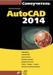
3. Самоучитель AutoCAD 2014 (автор: Н. Полищук©). Версия программы, для которой подходит эта книга: AutoCAD 2010-2016.
Краткое описание: Книга предназначена для освоения методики создания двумерных объектов и трехмерных моделей в системе AutoCAD 2014. Рассматриваются процессы параметризации, аннотирования и визуализации, средства коллективной работы с применением облачных ресурсов.
Советы по применению: эта книга хорошо дополняет бесплатный самоучитель по Автокаду, который содержит более 100 обучающих статей с практическими примерами и доп. материалом.
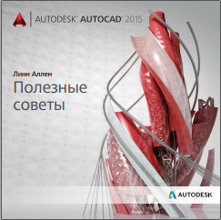
4. Полезные советы AutoCAD (автор: Линн Аллен©). Версия программы, для которой подходит эта книга: AutoCAD 2015-2016.
Краткое описание: AutoCAD 2015-2016 обеспечивает повышенное удобство работы и содержит множество функций, способных вывести ваши проекты на новый уровень!
Советы по применению: рекомендуется проходить обучение по этому пособию в связке с бесплатным курсом «5 принципов работы в AutoCAD, которые должен знать каждый». Курс доступен только подписчикам (получить видеоуроки AutoCAD).
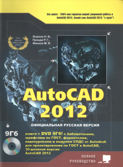
5. Полное руководство AutoCAD 2012 (автор: Н. Жарков©). Версия программы, для которой подходит эта книга: AutoCAD 2010-2016.
Краткое описание: Эта книга по Автокаду — руководство для тех, кто хочет с нуля освоить работу с данной программой и научиться проектированию на компьютере, созданию чертежей. Написана простым и доступным языком авторами-профессионалами, чьи книги по AutoCAD пользуются неизменной популярностью как хорошие учебные пособия.
Советы по применению: эта книга хорошо дополняет бесплатный самоучитель по Автокаду, является отличным помощником при прохождении углубленного курса «Использование AutoCAD на 100%», который позволяет изучить досконально программу в сжатые сроки.
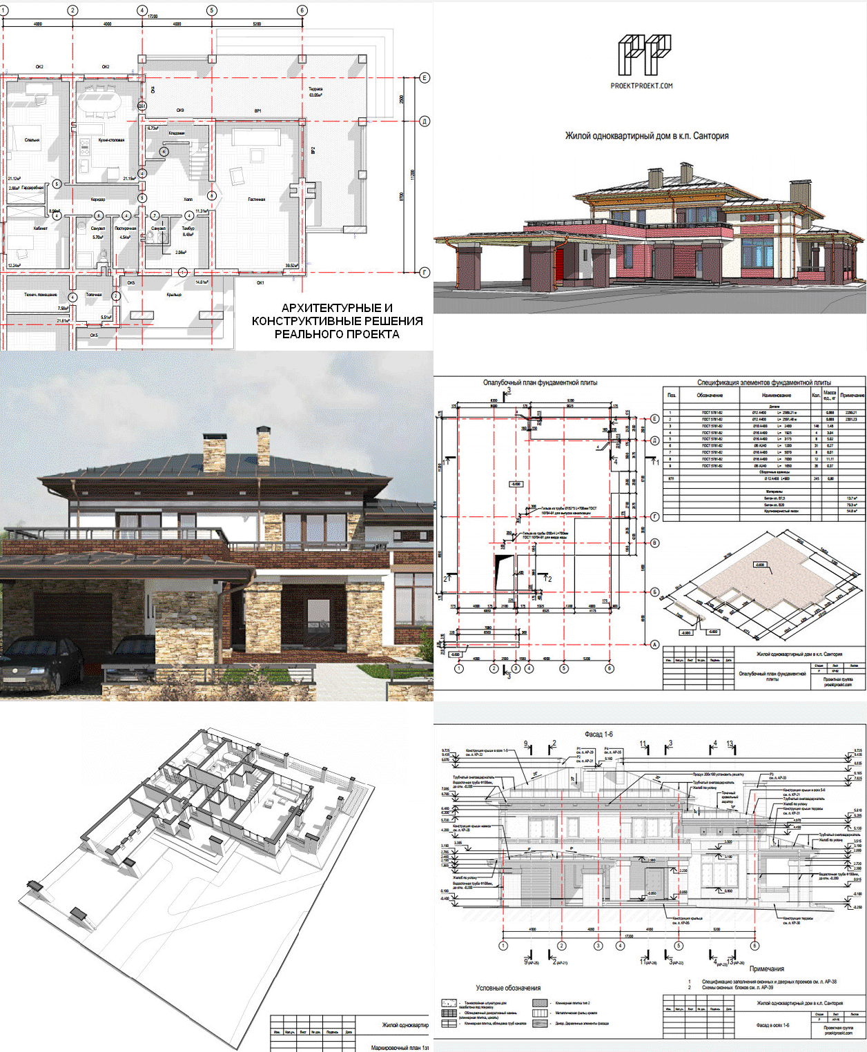
6. Архитектурные (АР) и конструктивные (КР) решения жилого дома (разработчик: PROEKTPROEKT.COM, формат документации: pdf-файлы).
Review the basic AutoCAD and AutoCAD LT controls.
After you launch AutoCAD, click New on the Start tab to begin a new drawing, or Open to work on an existing drawing.
Drawing Tabs
The new drawing,
Drawing1, starts on a new tab that’s just above the drawing area. You can click the tabs to switch between several open drawing files and the Start tab.
An asterisk (*) next to the drawing name indicates that the drawing needs to be saved. A quick way to close any drawing is to click the X control on its tab.
Go ahead and experiment with starting and opening drawings, and switching between the tabs. You can also drag the drawing tabs to reorder them.
The Ribbon
AutoCAD includes a standard tabbed ribbon across the top of the application. You can access nearly all the commands presented in this guide from the Home tab. In addition, the Quick Access toolbar shown below includes familiar commands such as New, Open, Save, Print, and Undo.
Note: If the Home tab is not the current tab, go ahead and click it.
The Command Window
At the heart of the program is the Command window, which is normally docked at the bottom of the application window. The Command window displays prompts, options, and messages.
You can enter commands directly in the Command window instead of using the ribbon, toolbars, and menus. Many long-time users prefer this method.
Notice that as you start to type a command, it completes automatically. When several possibilities are available such as in the example below, you can make your choice by clicking it or using the arrow keys and then pressing Enter or the Spacebar.
The Mouse
Most people use a mouse as their pointing device, but other devices have equivalent controls.
Tip: When you look for an option, try right-clicking. Depending on where you locate your cursor and whether you’re in command, the shortcut menu that displays provides relevant commands and options.
New Drawings
You can easily conform to industry or company standards by specifying settings for text, dimensions, linetypes, and several other features. For example, this backyard deck design displays two different dimension styles.
All these settings can be saved in a
drawing template file. Click New to choose from several drawing template files:
- For imperial drawings that assume your units are inches, use
acad.dwt
or
acadlt.dwt. - For metric units that assume your units are millimeters, use
acadiso.dwt or
acadltiso.dwt.
The «Tutorial» template files in the list are simple examples for the architectural or mechanical design disciplines with both imperial (i) and metric (m) versions. You might want to experiment with them when you start creating dimensions.
Most companies use drawing template files that conform to company standards. They will often use different drawing template files depending on the project or the client.
Create Your Own Drawing Template File
You can save any drawing (.dwg) file as a drawing template (.dwt) file. To create a new drawing template file based on an existing one, open the existing drawing template file, modify it, and then save it again with a different filename.
If you work independently, you can develop your drawing template files to suit your working preferences, adding settings for additional features as you become familiar with them. To modify an existing drawing template file, click Open, specify Drawing Template (*.dwt) in the Select File dialog box, and choose the drawing template file.
Important: If your company has already established a set of drawing template files, check with your CAD manager before modifying any of them.
Units
After you start a new drawing, you’ll first decide what the length of one unit represents—an inch, a foot, a centimeter, a kilometer, or some other unit of length. For example, the objects below could represent two buildings that are each 125 feet long, or they could represent a section from a mechanical part that is measured in millimeters.
Unit Display Settings
After you decide what unit of length that you want to use, the UNITS command lets you control several unit display settings including the following:
- Format (or Type). For example, a decimal length of 6.5 can be set to display as a fractional length of 6-1/2 instead.
- Precision. For example, a decimal length of 6.5 can be set to display as 6.50, 6.500, or 6.5000.
If you plan to work in feet and inches, use the UNITS command to set the unit type to Architectural, and then when you create objects, specify their lengths in inches. If you plan to use metric units, leave the unit type set to Decimal. Changing the unit format and precision does not affect the internal precision of your drawing. It affects only how lengths, angles, and coordinates are displayed in the user interface.
Tip: If you change a setting for the unit display or any other setting, you can save the settings in a drawing template file. Otherwise, you’ll need to change the settings for each new drawing.
Model Scale
Always create your models at full size (1:1 scale). The term
model refers to the geometry of your design. A
drawing includes the model geometry along with the views, notes, dimensions, callouts, tables, and the title block displayed in the layout.
You’ll specify the scale for printing a drawing on a standard-sized sheet later, when you create the layout.
Recommendations
- To open Help with information about the command in progress, simply press F1.
- To repeat the previous command, press Enter or the Spacebar.
- To see various options, select an object and right-click, or right-click a user interface element.
- To cancel a command in progress or if you ever feel stuck, press Esc. For example, if you click in the drawing area before entering a command, you’ll see something like the following:
Press Esc to cancel this preselection operation.
Нужна книга Автокад? Здесь вы можете бесплатно скачать самые популярные книги по AutoCAD в формате pdf для последних версий программы: самоучитель, руководство пользователя, Автокад для чайников и т.д.
Книги представляют собой вводный курс по использованию системы автоматизированного проектирования (САПР) AutoCAD различных версий. Материалы книг опробованы авторами на практике, и рассчитан на освоение в течение полутора недель. Основная часть книг построена на примере создания чертежа рабочей зоны. В книгах рассматривается весь процесс получения чертежей — от нанесения габаритов рабочей зоны до создания видов в ортогональных проекциях, расстановки размеров и вывода чертежа на печать с оформлением в соответствии с требованиями стандартов.
Книги рассчитаны на пользователей с минимальным уровнем подготовки в области информационных технологий. Наличие твердых навыков владения ПК, а также базового инженерного образования позволит сократить срок освоения AutoCAD с помощью данных книг до нескольких дней.

Краткое описание: Учебное пособие рассчитано на новичков, но и опытные специалисты могут найти для себя полезные советы! В результате прохождения данного курса вы охватите и освоите основные принципы черчения в среде AutoCAD.
Руководство пользователя AutoCAD (от Autodesk©)

Краткое описание: Автор: Алексей Меркулов©. Версия программы, для которой подходит эта книга: AutoCAD 2009-2016. Версия программы, для которой подходит эта книга: AutoCAD 2010-2016. Руководство пользователя AutoCAD содержит 2154 стр. и является незаменимым справочником, содержащим достоверное описание команд, инструментов и принципов работы в программе. Именно эта книга Автокад необходима для глубокого изучения программы.
Самоучитель AutoCAD 2014 (автор: Н.Полищук©)

Краткое описание: Версия программы, для которой подходит эта книга: AutoCAD 2010-2016. Книга предназначена для освоения методики создания двумерных объектов и трехмерных моделей в системе AutoCAD 2014. Рассматриваются процессы параметризации, аннотирования и визуализации, средства коллективной работы с применением облачных ресурсов.
Полезные советы AutoCAD (автор: Линн Аллен©)

Краткое описание:
Версия программы, для которой подходит эта книга: AutoCAD 2015-2016. AutoCAD 2015-2016 обеспечивает повышенное удобство работы и содержит множество функций, способных вывести ваши проекты на новый уровень!
Полное руководство AutoCAD 2012 (автор: Н. Жарков©)

Краткое описание: Версия программы, для которой подходит эта книга: AutoCAD 2010-2016. Эта книга по Автокаду — превосходное руководство и лучший выбор для всех, кто хочет с нуля освоить работу с данной программой и научиться проектированию на компьютере, созданию чертежей. Написана простым и доступным языком авторами-профессионалами, чьи книги по AutoCAD пользуются неизменной популярностью как хорошие учебные пособия.
Review the basic AutoCAD and AutoCAD LT controls.
After you launch AutoCAD, click New on the Start tab to begin a new drawing, or Open to work on an existing drawing.
Drawing Tabs
The new drawing,
Drawing1, starts on a new tab that’s just above the drawing area. You can click the tabs to switch between several open drawing files and the Start tab.
An asterisk (*) next to the drawing name indicates that the drawing needs to be saved. A quick way to close any drawing is to click the X control on its tab.
Go ahead and experiment with starting and opening drawings, and switching between the tabs. You can also drag the drawing tabs to reorder them.
The Ribbon
AutoCAD includes a standard tabbed ribbon across the top of the application. You can access nearly all the commands presented in this guide from the Home tab. In addition, the Quick Access toolbar shown below includes familiar commands such as New, Open, Save, Print, and Undo.
Note: If the Home tab is not the current tab, go ahead and click it.
The Command Window
At the heart of the program is the Command window, which is normally docked at the bottom of the application window. The Command window displays prompts, options, and messages.
You can enter commands directly in the Command window instead of using the ribbon, toolbars, and menus. Many long-time users prefer this method.
Notice that as you start to type a command, it completes automatically. When several possibilities are available such as in the example below, you can make your choice by clicking it or using the arrow keys and then pressing Enter or the Spacebar.
The Mouse
Most people use a mouse as their pointing device, but other devices have equivalent controls.
Tip: When you look for an option, try right-clicking. Depending on where you locate your cursor and whether you’re in a command, the shortcut menu that displays provides relevant commands and options.
New Drawings
You can easily conform to industry or company standards by specifying settings for text, dimensions, linetypes, and several other features. For example, this backyard deck design displays two different dimension styles.
All these settings can be saved in a
drawing template file. Click New to choose from several drawing template files:
- For imperial drawings that assume your units are inches, use
acad.dwt
or
acadlt.dwt. - For metric units that assume your units are millimeters, use
acadiso.dwt or
acadltiso.dwt.
The «Tutorial» template files in the list are simple examples for the architectural or mechanical design disciplines with both imperial (i) and metric (m) versions. You might want to experiment with them when you start creating dimensions.
Most companies use drawing template files that conform to company standards. They will often use different drawing template files depending on the project or the client.
Create Your Own Drawing Template File
You can save any drawing (.dwg) file as a drawing template (.dwt) file. To create a new drawing template file based on an existing one, open the existing drawing template file, modify it, and then save it again with a different filename.
If you work independently, you can develop your drawing template files to suit your working preferences, adding settings for additional features as you become familiar with them. To modify an existing drawing template file, click Open, specify Drawing Template (*.dwt) in the Select File dialog box, and choose the drawing template file.
Important: If your company has already established a set of drawing template files, check with your CAD manager before modifying any of them.
Units
After you start a new drawing, you’ll first decide what the length of one unit represents—an inch, a foot, a centimeter, a kilometer, or some other unit of length. For example, the objects below could represent two buildings that are each 125 feet long, or they could represent a section from a mechanical part that is measured in millimeters.
Unit Display Settings
After you decide what unit of length that you want to use, the UNITS command lets you control several unit display settings including the following:
- Format (or Type). For example, a decimal length of 6.5 can be set to display as a fractional length of 6-1/2 instead.
- Precision. For example, a decimal length of 6.5 can be set to display as 6.50, 6.500, or 6.5000.
If you plan to work in feet and inches, use the UNITS command to set the unit type to Architectural, and then when you create objects, specify their lengths in inches. If you plan to use metric units, leave the unit type set to Decimal. Changing the unit format and precision does not affect the internal precision of your drawing. It affects only how lengths, angles, and coordinates are displayed in the user interface.
Tip: If you change a setting for the unit display or any other setting, you can save the settings in a drawing template file. Otherwise, you’ll need to change the settings for each new drawing.
Model Scale
Always create your models at full size (1:1 scale). The term
model refers to the geometry of your design. A
drawing includes the model geometry along with the views, notes, dimensions, callouts, tables, and the title block displayed in the layout.
You’ll specify the scale for printing a drawing on a standard-sized sheet later, when you create the layout.
Recommendations
- To open Help with information about the command in progress, simply press F1.
- To repeat the previous command, press Enter or the Spacebar.
- To see various options, select an object and right-click, or right-click a user interface element.
- To cancel a command in progress or if you ever feel stuck, press Esc. For example, if you click in the drawing area before entering a command, you’ll see something like the following:
Press Esc to cancel this preselection operation.
AutoCAD, является одним из наиболее известных двух- и трёхмерных систем автоматизированного проектирования и черчения, разработанная компанией Autodesk. Впервые выпущенный Autodesk в 1982 году, он в настоящее время используется для широкого спектра приложений, включая архитектурные планы, макеты и чертежи деталей. Такая универсальность сделала AutoCAD стандартом для некоторых отраслей промышленности.
В этом учебном пособии вы изучите основы использования AutoCAD и создадите свои первые проекты. Сначала мы познакомимся с интерфейсом программы, а затем сразу перейдем к созданию 2D-чертежей. После этого мы перейдем к изучению 3D-моделирования.
Знакомимся с программой AutoCAD 2023. После запуска программы появляется экран приветствия.
Экран приветствия разделен на несколько областей.
Центральная часть экрана занимает область создания, которая позволяет открыть последние чертежи или любой чертеж указав путь к нему, а также создать новый чертеж.
В правой области экрана находится форма для входа в учетную запись, для получения доступа к облачному хранилищу образцов чертежей. Также отображается экран с уведомления об изменениях и новшествах.
Вверху находится главное меню для начала работы. Доступа к нему откроется только после открытия чертежа или после создания нового чертежа.
Для создания нового чертежа необходимо нажать стрелку возле кнопки “Создать” и указать шаблон. Для создания 2D чертежа нужно указывать шаблон acadiso.dwt. При необходимости создания чертежа на основе другого шаблона выбирается пункт “Обзор шаблонов…”.
После создания хотя бы одного чертежа, в дальнейшем выбирать шаблон не обязательно. При создании нового чертежа при нажатии на кнопку создать будет выбран последний выбранный шаблон. В нашем случае шаблон acadiso.dwt.
После создания нового чертежа открывается рабочая область чертежа и вверху активируется главное меню
В левой верхней части рабочего пространства находится панель быстрого доступа. Ниже нее находится лента меню, разбитое на разделы и вкладки для управления инструментами. Раздел меню “Главная” включает в себя инструменты для рисования, редактирования, работы с аннотациями, свойствами, слоями и блоками. Все необходимые функции для создания чертежей находятся в этом меню. А всякие дополнения такие как специальные размеры, импорт/экспорт данных, связи с данными находятся в других меню.
Ниже ленты меню находится панель вкладок. Данной панелью можно управлять как в браузере. Создавать новый документ можно нажатием на “+”. Порядок вкладок можно менять перетягиванием.
Под панелью вкладок в левой центральной части предпочтительно держать открытой панель свойств объектов. Данная панель дает информацию о выделенных и создаваемых объектах и предоставляет возможность повлиять на свойства объектов. Можно изменять такие свойства как цвет, слой, тип линий, масштаб, вес линий и другие, т.е. основные важные свойства.
Центральное место занимает рабочее место, называемое пространством модели. На котором создаваемые модели создаются в 3D пространстве, но формате 2D плоскостей. В правом верхнем углу пространства модели находится видовой куб, который позволяет управлять 3D пространством для обзора под различными углами проектируемых моделей. По умолчанию отображается вид сверху, который можно изменять изменить вращая куб перетягиванием захватив куб или нажимая на стрелки изменения вида. Также на рабочем пространстве модели в качестве ориентира установлена система координат с осями “Х” и “Y”. Для проектирования в формате 2D нужно придерживаться вида сверху и расположения оси “Х” вправо а оси “Y” вверх.
В самом низу справа находится панель с вкладками модели и листами.
На вкладке модели находится основное рабочее пространство на котором создаются все чертежи, модели, надписи. На вкладке Листы формируется элементы для печати т.е. вывода на принтер или для сохранения в формате pdf.
Под пространством модели располагается командная строка или меню команд.
Командная строка предназначена для быстрых операций редактирования, показывает все последовательности действий. В командной строке вводятся команды, при начале ввода текста появляется список предлагаемых команд для ввода. При работе с инструментами в командной строке отображаются динамические кнопки управления инструментами.
В правой нижней части находится строка состояния в которой отображаются средства для создания чертежей, масштабирования, аннотаций.

