-
Contents
-
Table of Contents
-
Troubleshooting
-
Bookmarks
Related Manuals for CUMMINS ISB
Summary of Contents for CUMMINS ISB
-
Page 1
Service Manual , ISB, and QSB (Common Rail Fuel System) Volume 1… -
Page 2
Service Manual , ISB, and QSB (Common Rail Fuel System) Volume 1 Copyright© 2014 Bulletin 4021271 Cummins Inc. Printed 29-OCTOBER-2014 All rights reserved To buy Cummins Parts and Service Manuals, Training Guides, or Tools go to our website at https://store.cummins.com… -
Page 3
The specifications and rebuild information in this manual are based on the information in effect at the time of printing. Cummins Inc. reserves the right to make any changes at any time without obligation. If differences are found between your engine and the information in this manual, contact a Cummins Authorized Repair Location or call 1-800-DIESELS (1-800-343-7357) toll free in the U.S. -
Page 4
Cylinder Block — Group 01 ……………………..Cylinder Head — Group 02 ……………………..Rocker Levers — Group 03 ……………………..Cam Followers/Tappets — Group 04 ……………………. Back …………………………….back To buy Cummins Parts and Service Manuals, Training Guides, or Tools go to our website at https://store.cummins.com… -
Page 5
To buy Cummins Parts and Service Manuals, Training Guides, or Tools go to our website at https://store.cummins.com… -
Page 6: Table Of Contents
General Safety Instructions ……………………….i-8 Important Safety Notice………………………….i-8 How to Use the Manual …………………………i-2 General Information…………………………i-2 Illustrations ……………………………..i-7 General Information…………………………i-7 Symbols …………………………….i-3 General Information…………………………i-3 To buy Cummins Parts and Service Manuals, Training Guides, or Tools go to our website at https://store.cummins.com…
-
Page 7
ISB, ISBe and QSB (Common Rail […] Page i-b Section i — Introduction This Page Left Intentionally Blank… -
Page 8: About The Manual
Additionally the manual is intended to aid mechanics in disassembly, inspecting parts for reuse, rebuilding and assembly of components. The manual is divided into sections. Each section is equivalent to a group used in Cummins’ filmcard system. Some sections contain reference numbers and procedure numbers. Reference numbers provide general information, specifications, diagrams, and service tools where applicable.
-
Page 9: How To Use The Manual
How to Use the Manual General Information This manual is divided into the same group system used for previous manuals and the Cummins’ filmcard system. Section 00 is organized into a logical sequence of engine disassemble/assemble, all other sections are in numerical sequence.
-
Page 10: Symbols
Minor personal injury can result or a part, and assembly, or the engine can be damaged if the caution instructions are not followed. Indicates a REMOVAL or Dissassembly step. To buy Cummins Parts and Service Manuals, Training Guides, or Tools go to our website at https://store.cummins.com…
-
Page 11
Section i — Introduction Indicates an INSTALLATION or ASSEMBLY step. INSPECTION is required. CLEAN the part or assembly. PERFORM a mechanical or time MEASUREMENT. To buy Cummins Parts and Service Manuals, Training Guides, or Tools go to our website at https://store.cummins.com… -
Page 12
LUBRICATE the part or assembly. Indicates that a WRENCH or TOOL SIZE will be given. TIGHTEN to a specific torque. PERFORM an electrical MEASUREMENT. To buy Cummins Parts and Service Manuals, Training Guides, or Tools go to our website at https://store.cummins.com… -
Page 13
The component weighs 23kg [50 lbs] or more. To reduce the possibility of personal injury, use a hoist or get assistance to lift the component. To buy Cummins Parts and Service Manuals, Training Guides, or Tools go to our website at https://store.cummins.com… -
Page 14: Illustrations
The illustrations are intended to show repair or replacement procedures. The procedure will be the same for all applications, although the illustration can differ. To buy Cummins Parts and Service Manuals, Training Guides, or Tools go to our website at https://store.cummins.com…
-
Page 15: General Safety Instructions
All fasteners must be replaced on re-fitting the guards. • Do not perform any repair when fatigued or after consuming alcohol or drugs that can impair your functioning. To buy Cummins Parts and Service Manuals, Training Guides, or Tools go to our website at https://store.cummins.com…
-
Page 16
California Proposition 65 Warning — Diesel engine exhaust and some of its constituents are known to the State of California to cause cancer, birth defects, and other reproductive harm. To buy Cummins Parts and Service Manuals, Training Guides, or Tools go to our website at https://store.cummins.com… -
Page 17: General Repair Instructions
• Perform the inspections specified in the procedures • Replace all components or assemblies which are damaged or worn beyond the specifications To buy Cummins Parts and Service Manuals, Training Guides, or Tools go to our website at https://store.cummins.com…
-
Page 18: Welding On A Vehicle With An Electronic Controlled Fuel System
The assembly instructions have been written to use again as many components and assemblies as possible. When it is necessary to replace a component or assembly, the procedure is based on the use of new Cummins or Cummins ReCon® components. All of the repair services described in this manual are available from all Cummins Distributors and most Dealer locations.
-
Page 19: General Cleaning Instructions
Cummins Inc. does not recommend sanding or grinding the carbon ring at the top of cylinder liners until clean metal is visible. The liner will be ruined and any signs of a problem at the top ring reversal point (like a dust-out) will be destroyed.
-
Page 20: Gasket Surfaces
The object of cleaning gasket surfaces is to remove any gasket material, not refinish the gasket surface of the part. Cummins Inc. does not recommend any specific brand of liquid gasket remover. If a liquid gasket remover is used, check the directions to make sure the material being cleaned will not be harmed.
-
Page 21: Plastic Bead Cleaning
Plastic Bead Cleaning Cummins Inc. does not recommend the use of glass bead blast or walnut shell media on any engine part. Cummins Inc. recommends using only plastic bead media, Part Number 3822735 or equivalent on any engine part. Never use sand as a blast media to clean engine parts.
-
Page 22: Fuel System
Cummins Inc. now recommends glass bead media NOT used to clean any engine parts. Glass media is too easily embedded into the material particularly in soft materials and when air pressures greater than media manufacturer’s recommend are used.
-
Page 23
Clean and dry the tools before returning them to the tool box. • If possible, store fuel system tools in sealed containers. • Make sure fuel system tools are clean before use. To buy Cummins Parts and Service Manuals, Training Guides, or Tools go to our website at https://store.cummins.com… -
Page 24: Acronyms And Abbreviations
Liquified Petroleum Gas Low Temperature Aftercooling MCRS Modular Common Rail System Malfunction Indicator Lamp Megapascal Miles Per Hour Miles Per Quart N•m Newton-meter To buy Cummins Parts and Service Manuals, Training Guides, or Tools go to our website at https://store.cummins.com…
-
Page 25
Selective Catalytic Reduction Step Timing Control Subsystem Identification Descriptions Top Dead Center Volts of Direct Current Variable Geometry Turbocharger Variable Speed Vehicle Speed Sensor To buy Cummins Parts and Service Manuals, Training Guides, or Tools go to our website at https://store.cummins.com… -
Page 26
Cummins® Service Engine Model Product Identification ………………E-45 General Information…………………………E-45 Engine Diagrams …………………………..E-6 Engine Views…………………………..E-6 Engine Identification …………………………E-1 Cummins® Engine Nomenclature……………………..E-3 ECM Dataplate…………………………..E-4 Engine Dataplate…………………………..E-1 Fuel Injection Pump Dataplate………………………E-4 To buy Cummins Parts and Service Manuals, Training Guides, or Tools go to our website at https://store.cummins.com… -
Page 27
ISB, ISBe and QSB (Common Rail […] Page E-b Section E — Engine and System Identification This Page Left Intentionally Blank… -
Page 28: Engine Identification
1 Engine serial number 2 Control parts list (CPL) 3 Model 4 Horsepower and rpm rating. To buy Cummins Parts and Service Manuals, Training Guides, or Tools go to our website at https://store.cummins.com…
-
Page 29
(CPL) provide information for service and for ordering parts. The engine dataplate must not be changed unless approved be changed unless approved by Cummins Inc. To buy Cummins Parts and Service Manuals, Training Guides, or Tools go to our website at https://store.cummins.com… -
Page 30
Marine Applications The Cummins MerCruiser Diesel engine nomenclature provides the engine model, displacement in liters and horsepower rating. To buy Cummins Parts and Service Manuals, Training Guides, or Tools go to our website at https://store.cummins.com… -
Page 31: Fuel Injection Pump Dataplate
NOTE: The presence of an ECM dataplate depends on the manufacturing plant andthe date the engine was manufactured. If an ECM dataplate was not installed by the manufacturing plant, calibration data can be found on the engine dataplate. To buy Cummins Parts and Service Manuals, Training Guides, or Tools go to our website at https://store.cummins.com…
-
Page 32
If an ECM dataplate was not installed by the manufacturing plant, calibration data can be found on the engine dataplate. To buy Cummins Parts and Service Manuals, Training Guides, or Tools go to our website at https://store.cummins.com… -
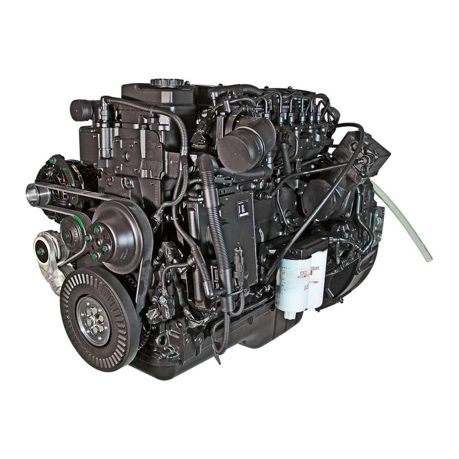
Page 33: Engine Views
Some external components will be at different locations for different engine models. NOTE: The illustrations are only a reference to show a typical engine. To buy Cummins Parts and Service Manuals, Training Guides, or Tools go to our website at https://store.cummins.com…
-
Page 34
15 Ambient air pressure sensor (internal to ECM) 16 Fuel inlet to cooling plate 17 Air intake inlet 18 Coolant outlet 19 Rail pressure sensor 20 Fuel rail. To buy Cummins Parts and Service Manuals, Training Guides, or Tools go to our website at https://store.cummins.com… -
Page 35
15 Ambient air pressure sensor (internal to ECM) 16 Fuel inlet to cooling plate 17 Air intake inlet 18 Coolant outlet 19 Rail pressure sensor 20 Fuel rail. To buy Cummins Parts and Service Manuals, Training Guides, or Tools go to our website at https://store.cummins.com… -
Page 36
8 Fan or PTO drive flange mounting 9 Starter 10 Water pump 11 Coolant inlet 12 Belt tensioner 13 Alternator 14 Coolant outlet 15 Coolant temperature sensor. To buy Cummins Parts and Service Manuals, Training Guides, or Tools go to our website at https://store.cummins.com… -
Page 37
8 Fan or PTO drive flange mounting 9 Starter 10 Water pump 11 Coolant inlet 12 Belt tensioner 13 Alternator 14 Coolant outlet 15 Coolant temperature sensor. To buy Cummins Parts and Service Manuals, Training Guides, or Tools go to our website at https://store.cummins.com… -
Page 38
2 Air outlet from turbocharger 3 Air inlet to turbocharger 4 Flywheel 5 Flywheel housing 6 Crankcase breather tube 7 Fuel return line 8 Engine lifting brackets. To buy Cummins Parts and Service Manuals, Training Guides, or Tools go to our website at https://store.cummins.com… -
Page 39
2 Air outlet from turbocharger 3 Air inlet to turbocharger 4 Flywheel 5 Flywheel housing 6 Crankcase breather tube 7 Fuel return line 8 Engine lifting brackets. To buy Cummins Parts and Service Manuals, Training Guides, or Tools go to our website at https://store.cummins.com… -
Page 40
4 Coolant inlet 5 Oil filter 6 Oil pan drain plug 7 Turbocharger exhaust outlet 8 Starter 9 Flywheel housing 10 Turbocharger compressor inlet. To buy Cummins Parts and Service Manuals, Training Guides, or Tools go to our website at https://store.cummins.com… -
Page 41
4 Coolant inlet 5 Oil filter 6 Oil pan drain plug 7 Turbocharger exhaust outlet 8 Starter 9 Flywheel housing 10 Turbocharger compressor inlet. To buy Cummins Parts and Service Manuals, Training Guides, or Tools go to our website at https://store.cummins.com… -
Page 42
12 Engine speed sensor (crankshaft) 13 Tone wheel 14 Coolant temperature sensor 15 Vibration damper 16 Coolant outlet 17 Alternator 18 Oil pressure/temperature sensor 19 Exhaust manifold. To buy Cummins Parts and Service Manuals, Training Guides, or Tools go to our website at https://store.cummins.com… -
Page 43
12 Engine speed sensor (crankshaft) 13 Tone wheel 14 Vibration damper 15 Coolant temperature sensor 16 Coolant outlet 17 Alternator 18 Oil pressure/temperature sensor 19 Exhaust manifold. To buy Cummins Parts and Service Manuals, Training Guides, or Tools go to our website at https://store.cummins.com… -
Page 44
9 Engine speed sensor (crankshaft) 10 Electronic control module (ECM) 11 Engine position sensor (camshaft) 12 Air intake inlet 13 Rail pressure sensor 14 Dipstick To buy Cummins Parts and Service Manuals, Training Guides, or Tools go to our website at https://store.cummins.com… -
Page 45
7 Vibration damper 8 Water pump 9 Starter 10 Belt tensioner 11 Alternator 12 Coolant outlet 13 Coolant temperature sensor 14 Turbocharger air outlet To buy Cummins Parts and Service Manuals, Training Guides, or Tools go to our website at https://store.cummins.com… -
Page 46
1 Rear engine lifting bracket 2 Turbocharger exhaust outlet 3 Clutch mounting holes 4 Flywheel housing 5 Flywheel/flexplate 6 Crankcase breather tube 7 Injector drain line To buy Cummins Parts and Service Manuals, Training Guides, or Tools go to our website at https://store.cummins.com… -
Page 47
4 Lubricating oil cooler 5 Oil filter 6 Oil pan drain plug 7 Turbocharger exhaust outlet 8 Starter 9 Flywheel housing 10 Turbocharger compressor inlet. To buy Cummins Parts and Service Manuals, Training Guides, or Tools go to our website at https://store.cummins.com… -
Page 48
8 Tone wheel 9 Vibration damper 10 Coolant temperature sensor 11 Coolant outlet 12 Alternator 13 Exhaust manifold 14 Rail pressure relief valve To buy Cummins Parts and Service Manuals, Training Guides, or Tools go to our website at https://store.cummins.com… -
Page 49
12 Dipstick/oil level sensor 13 Electronic control module (ECM) 14 Air intake inlet 15 Coolant outlet 16 Fuel rail pressure relief valve 17 Fuel rail. To buy Cummins Parts and Service Manuals, Training Guides, or Tools go to our website at https://store.cummins.com… -
Page 50
7 Fan or PTO drive flange mounting 8 Starter mounting location 9 Coolant inlet 10 Water pump 11 Belt tensioner 12 Alternator 13 Coolant outlet 14 Coolant temperature sensor. To buy Cummins Parts and Service Manuals, Training Guides, or Tools go to our website at https://store.cummins.com… -
Page 51
2 Air outlet from turbocharger 3 Air inlet to turbocharger 4 Flywheel 5 Flywheel housing 6 Crankcase breather tube 7 Fuel return line 8 Engine lifting brackets. To buy Cummins Parts and Service Manuals, Training Guides, or Tools go to our website at https://store.cummins.com… -
Page 52
4 Coolant inlet 5 Oil filter 6 Oil pan drain plug 7 Turbocharger exhaust outlet 8 Starter 9 Flywheel housing 10 Turbocharger compressor inlet. To buy Cummins Parts and Service Manuals, Training Guides, or Tools go to our website at https://store.cummins.com… -
Page 53
9 High-pressure fuel lines 10 Oil fill cap 11 Tone wheel 12 Coolant temperature sensor 13 Vibration damper (Optional) 14 Coolant outlet 15 Exhaust manifold. To buy Cummins Parts and Service Manuals, Training Guides, or Tools go to our website at https://store.cummins.com… -
Page 54
16 Electronic control module (ECM) 17 Engine speed sensor (camshaft) 18 Air intake inlet 19 EGR temperature sensor 20 Fuel heater 21 Rail pressure sensor. To buy Cummins Parts and Service Manuals, Training Guides, or Tools go to our website at https://store.cummins.com… -
Page 55
14 Starter 15 Coolant inlet 16 Belt tensioner 17 Water pump 18 Freon compressor 19 Alternator 20 Coolant outlet 21 Coolant temperature sensor. To buy Cummins Parts and Service Manuals, Training Guides, or Tools go to our website at https://store.cummins.com… -
Page 56
7 Flywheel 8 Gear housing 9 Crankcase breather 10 Fuel out (return to tank) 11 Coolant connection for air compressor 12 Fuel return line. To buy Cummins Parts and Service Manuals, Training Guides, or Tools go to our website at https://store.cummins.com… -
Page 57
12 Turbocharger speed sensor 13 Turbocharger exhaust outlet 14 Starter 15 Flywheel housing 16 Gear housing 17 EGR cooler 18 EGR valve 19 EGR actuator. To buy Cummins Parts and Service Manuals, Training Guides, or Tools go to our website at https://store.cummins.com… -
Page 58
13 EGR differential pressure sensor 14 Tone wheel 15 Vibration damper 16 Oil fill cap 17 Coolant temperature sensor 18 Coolant outlet 19 Alternator 20 Oil filter. To buy Cummins Parts and Service Manuals, Training Guides, or Tools go to our website at https://store.cummins.com… -
Page 59
Engine Diagrams ISB, ISBe and QSB (Common Rail […] Page E-32 Section E — Engine and System Identification To buy Cummins Parts and Service Manuals, Training Guides, or Tools go to our website at https://store.cummins.com… -
Page 60
10 Mounting brackets 11 Oil pan 12 Lubricating oil drain 13 Belt and pulley guards 14 Lubricating oil filter 15 Lubricating oil filter head inlet. To buy Cummins Parts and Service Manuals, Training Guides, or Tools go to our website at https://store.cummins.com… -
Page 61
19 Fuel return from high pressure fuel pump 20 Crankshaft speed sensor 21 Camshaft speed sensor 22 Oil pressure sensor 23 Fuel pump 24 Fuel cooler 25 Sea water pump. To buy Cummins Parts and Service Manuals, Training Guides, or Tools go to our website at https://store.cummins.com… -
Page 62
18 Closed crankcase breather oil drain line 19 Flywheel housing 20 Heat exchanger engine coolant outlet 21 Heat exchanger sea water inlet 22 Marine gear oil cooler 23 Turbocharger To buy Cummins Parts and Service Manuals, Training Guides, or Tools go to our website at https://store.cummins.com… -
Page 63
9 Flywheel housing 10 Flywheel 11 Aftercooler air inlet 12 Aftercooler zinc anode 13 Marine gear oil cooler 14 Air cleaner and filter. To buy Cummins Parts and Service Manuals, Training Guides, or Tools go to our website at https://store.cummins.com… -
Page 64
18 Exhaust outlet connection 19 Closed crankcase breather blow-by connection 20 Air inlet restriction indicator 21 Air cleaner connection 22 Closed crankcase breather/air cleaner assembly To buy Cummins Parts and Service Manuals, Training Guides, or Tools go to our website at https://store.cummins.com… -
Page 65
4 Exhaust elbow 5 Tailstock assembly 6 Driveshaft 7 Trim cylinder zinc anode 8 Ventilation plate zinc anode 9 Sterndrive™ 10 Trim cylinder. To buy Cummins Parts and Service Manuals, Training Guides, or Tools go to our website at https://store.cummins.com… -
Page 66
4 Bearing support assembly 5 Tailstock assembly 6 Driveshaft 7 Trim cylinder 8 Ventilation plate zinc anode (bottom of ventilation plate) 9 Trim cylinder zinc anode. To buy Cummins Parts and Service Manuals, Training Guides, or Tools go to our website at https://store.cummins.com… -
Page 67
5 Gear oil drain plug 6 Sea water outlet valve 7 Transmission drain 8 Steering and transmission oil cooler 9 Exhaust outlet connection. To buy Cummins Parts and Service Manuals, Training Guides, or Tools go to our website at https://store.cummins.com… -
Page 68
6 Propeller shaft 7 Drive skeg 8 Gear housing 9 Sea water inlet and seacock 10 Drive shaft (under shield) 11 Drive shaft shield. To buy Cummins Parts and Service Manuals, Training Guides, or Tools go to our website at https://store.cummins.com… -
Page 69
Section E — Engine and System Identification Zeus™ 3500 (Top View) 1 Transmission dipstick 2 Steering and transmission fluid reservoir fill 3 Transmission filter. To buy Cummins Parts and Service Manuals, Training Guides, or Tools go to our website at https://store.cummins.com… -
Page 70
Engine Diagrams Section E — Engine and System Identification Page E-43 Zeus™ 3500 Drop Box (Starboard View) 1 Exhaust riser 2 Transmission drop box. To buy Cummins Parts and Service Manuals, Training Guides, or Tools go to our website at https://store.cummins.com… -
Page 71
ISB, ISBe and QSB (Common Rail […] Page E-44 Section E — Engine and System Identification Zeus™ 3500 Drop Box (Port View) 1 Drop box drain plug To buy Cummins Parts and Service Manuals, Training Guides, or Tools go to our website at https://store.cummins.com… -
Page 72
If the engine operates on a fuel type other than diesel, the type will be identified after the liter size. To buy Cummins Parts and Service Manuals, Training Guides, or Tools go to our website at https://store.cummins.com… -
Page 73
Example: 1 On-Highway automotive «X» 15 liter engine 2 Control system number 871 3 Technology supported; Electric EGR and Diesel Particulate Filter To buy Cummins Parts and Service Manuals, Training Guides, or Tools go to our website at https://store.cummins.com… -
Page 74
Modular Common Rail System Used only on QSK19, 38, 50 , 60 MCRS HHP Engines Integrated Dosing Control Unit Not Used None Integrated To buy Cummins Parts and Service Manuals, Training Guides, or Tools go to our website at https://store.cummins.com… -
Page 75
Cummins® Service Engine Model Product Identification ISB, ISBe and QSB (Common Rail […] Page E-48 Section E — Engine and System Identification Notes… -
Page 76
Fuel System — Overview ………………………..F-6 General Information…………………………F-6 Injectors and Fuel Lines — Overview ……………………F-14 General Information…………………………F-14 Lubricating Oil System — Overview …………………….F-16 General Information…………………………F-16 To buy Cummins Parts and Service Manuals, Training Guides, or Tools go to our website at https://store.cummins.com… -
Page 77
ISB, ISBe and QSB (Common Rail […] Page F-b Section F — Familiarization This Page Left Intentionally Blank… -
Page 78
General Information Connecting Rods This familiarization section helps to identify and orient the various styles of ISB connecting rods for installation. These details are important because some connecting rods are not marked with a part number and identification can be difficult. -
Page 79
ISB 4.5, ISB 6.7 Connecting Rod Joint: Machined Cylinder Bore: 107 mm [4.212 in] Cylinder Stroke: 124 mm [4.881 in] Orientation: Through hole toward camshaft To buy Cummins Parts and Service Manuals, Training Guides, or Tools go to our website at https://store.cummins.com… -
Page 80
ISB 4.5, ISB 6.7 Connecting Rod Joint: Fractured Cylinder Bore: 107 mm [4.212 in] Cylinder Stroke: 124 mm [4.881 in] Orientation: Blind hole toward camshaft To buy Cummins Parts and Service Manuals, Training Guides, or Tools go to our website at https://store.cummins.com… -
Page 81
Use the following illustrations to identify 3.9 Liter, 4.5 Liter, 5.9 Liter, and 6.7 Liter (6 cylinder) connecting rods. Note: Lead-free bushings (10) Part Numbers 4983518 and 5257363 are not serviceable. Connecting Rod Characteristics 1 Balancer 2 Machined surface To buy Cummins Parts and Service Manuals, Training Guides, or Tools go to our website at https://store.cummins.com… -
Page 82
9 Oil grooves in leaded bushing Part Number 4891178 5 Smooth 10 Oil grooves in lead-free bushings Part Numbers 4983518/5257363. (These bushings 6 Single dimple serviceable) 7 Three dimple To buy Cummins Parts and Service Manuals, Training Guides, or Tools go to our website at https://store.cummins.com… -
Page 83
The fuel that enters the high-pressure fuel pump is pressurized between 250 and 1800 bar [3626 to 26107 psi] by three radial pumping chambers. An M-Prop valve, or electronic fuel control (EFC) valve, at the inlet to the three radial To buy Cummins Parts and Service Manuals, Training Guides, or Tools go to our website at https://store.cummins.com… -
Page 84
Exceeding the maximum capacity will cause the gauge to read incorrectly. If the maximum is exceeded, check the gauge against a reference gauge. To buy Cummins Parts and Service Manuals, Training Guides, or Tools go to our website at https://store.cummins.com… -
Page 85
NOTE: Always use the same size and material of line or hoses that were originally supplied with the gauge. To buy Cummins Parts and Service Manuals, Training Guides, or Tools go to our website at https://store.cummins.com… -
Page 86
Tools required to troubleshoot the common rail system include: • M10 Compuchek® fittings • Orificed diagnostic fuel line, 0.043 mm [.002 in] To buy Cummins Parts and Service Manuals, Training Guides, or Tools go to our website at https://store.cummins.com… -
Page 87
Maximum high pressure pump leakage 300 cc [.32 quart] per 30 seconds @ 1500 rpm 300 cc [.32 quart] per 30 seconds @ cranking To buy Cummins Parts and Service Manuals, Training Guides, or Tools go to our website at https://store.cummins.com… -
Page 88
NOTE: * Engines are either equipped with an air cooled or fuel cooled ECM. If an air cooled ECM is used, the fuel enters the engine from the OEM connection at the gear pump inlet. To buy Cummins Parts and Service Manuals, Training Guides, or Tools go to our website at https://store.cummins.com… -
Page 89
14 High-pressure connector to fuel injector 15 Fuel injector 16 Injector return line 17 Pressure relief return line 18 Fuel pump return line 19 Fuel return manifold. To buy Cummins Parts and Service Manuals, Training Guides, or Tools go to our website at https://store.cummins.com… -
Page 90
18 Injector return line 19 Fuel pump to fuel manifold return 20 Fuel manifold to fuel cooler 21 Fuel cooler 22 Fuel return to tank. To buy Cummins Parts and Service Manuals, Training Guides, or Tools go to our website at https://store.cummins.com… -
Page 91
NOTE: The edge filters are not a substitute for cleaning and covering all fuel system connections during repair. Edge filters are not a substitute for maintaining the recommended engine mounted fuel filter. To buy Cummins Parts and Service Manuals, Training Guides, or Tools go to our website at https://store.cummins.com… -
Page 92
Exceeding the maximum capacity will cause the gauge to read incorrectly. If the maximum is exceeded, check the gauge against a reference gauge. To buy Cummins Parts and Service Manuals, Training Guides, or Tools go to our website at https://store.cummins.com… -
Page 93
This is due to the fact that all B series engines use sliding tappets. NOTE: If CI/SK oils are not available, see the appropriate Operation and Maintenance manual for your engine for alternatives. To buy Cummins Parts and Service Manuals, Training Guides, or Tools go to our website at https://store.cummins.com… -
Page 94
When the diagnosing lubricating system malfunctions, check all obvious items related to oil pressure, such as gauges, high level, excessive contamination, and oil viscosity. To buy Cummins Parts and Service Manuals, Training Guides, or Tools go to our website at https://store.cummins.com… -
Page 95
To buy Cummins Parts and Service Manuals, Training Guides, or Tools go to our website at https://store.cummins.com… -
Page 96
The engine will have low pressure or no oil pressure during starting, followed by normal oil pressure. To buy Cummins Parts and Service Manuals, Training Guides, or Tools go to our website at https://store.cummins.com… -
Page 97
Coolant in the oil can be caused by: • Expansion plugs leaking • Oil cooler element leaking • Damaged cylinder head or gasket • Cracked engine block • Casting porosity. To buy Cummins Parts and Service Manuals, Training Guides, or Tools go to our website at https://store.cummins.com… -
Page 98
Lubricating oil drain plug. Refer to Procedure Procedure 007-037. Leaks indicate defective oil cooler, cylinder head gasket, or cracked cylinder head or block. To buy Cummins Parts and Service Manuals, Training Guides, or Tools go to our website at https://store.cummins.com… -
Page 99
An injector leak will also cause the engine to run rough and have low power. Remove and repair, or replace leaking injectors. Refer to Procedure Procedure 006-026 To buy Cummins Parts and Service Manuals, Training Guides, or Tools go to our website at https://store.cummins.com… -
Page 100
NOTE: If the engine experiences a turbocharger failure or any other occasion where oil or debris is put into the charge air cooler, the charge air cooler must be cleaned. To buy Cummins Parts and Service Manuals, Training Guides, or Tools go to our website at https://store.cummins.com… -
Page 101
Also, a failed air compressor head gasket or cylinder head gasket can allow oil to leak into the coolant or coolant to leak into the oil during a hot shutdown. To buy Cummins Parts and Service Manuals, Training Guides, or Tools go to our website at https://store.cummins.com… -
Page 102
10 Filter bypass valve open 11 To lubricating oil filter 12 Full-flow lubricating oil filter 13 From lubricating oil filter 14 Main lubricating oil rifle. To buy Cummins Parts and Service Manuals, Training Guides, or Tools go to our website at https://store.cummins.com… -
Page 103
© Cummins Inc. © Cummins Inc. 07d00074 Lubrication for the Turbocharger, Non Marine Engines 1 Turbocharger lubricating oil supply 2 Turbocharger lubricating oil drain. To buy Cummins Parts and Service Manuals, Training Guides, or Tools go to our website at https://store.cummins.com… -
Page 104
2 Filtered oil supply to main oil rifle 3 Lubricating oil cooler 4 Unfiltered lubricating oil to filter 5 Turbocharger lubricating oil supply 6 Turbocharger lubricating oil drain. To buy Cummins Parts and Service Manuals, Training Guides, or Tools go to our website at https://store.cummins.com… -
Page 105
6 To camshaft 7 Crankshaft main journal 8 Oil supply to rod bearings 9 Directed piston-cooling nozzle 10 To internal lubrication of air compressor. To buy Cummins Parts and Service Manuals, Training Guides, or Tools go to our website at https://store.cummins.com… -
Page 106
1 Main lubricating oil rifle 2 Rocker lever support 3 Transfer slot 4 Rocker lever shaft 5 Rocker lever bore 6 Rocker lever. To buy Cummins Parts and Service Manuals, Training Guides, or Tools go to our website at https://store.cummins.com… -
Page 107
Lubrication for the Accessory Drive 1 Oil feed from block 2 Oil supply to accessory drive. NOTE: Oil returns to pan through the gear housing. To buy Cummins Parts and Service Manuals, Training Guides, or Tools go to our website at https://store.cummins.com… -
Page 108
On engines with EGR, the vent pipe plug located in the EGR cooler bundle return must be removed any time the engine is filled with coolant. To buy Cummins Parts and Service Manuals, Training Guides, or Tools go to our website at https://store.cummins.com… -
Page 109
Refer to Procedure Procedure 007-999 (Lubricating Oil System- Overview). NOTE: Transmission fluid can also leak into the coolant through radiator bottom tank transmission oil coolers. To buy Cummins Parts and Service Manuals, Training Guides, or Tools go to our website at https://store.cummins.com… -
Page 110
8 Coolant bypass passage 9 Coolant flow back to radiator 10 Bypass open 11 Coolant bypass in cylinder head 12 Coolant flow to water pump inlet. To buy Cummins Parts and Service Manuals, Training Guides, or Tools go to our website at https://store.cummins.com… -
Page 111
8 Coolant flow from cylinder block to turbocharger bearing housing 9 Coolant flow return from turbocharger bearing housing back to the rear of the cylinder head. To buy Cummins Parts and Service Manuals, Training Guides, or Tools go to our website at https://store.cummins.com… -
Page 112
12 Turbocharger vent line 13 Cylinder head vent line 14 Exhaust manifold vent line 15 Coolant recovery bottle 16 Heat exchanger zinc anode. To buy Cummins Parts and Service Manuals, Training Guides, or Tools go to our website at https://store.cummins.com… -
Page 113
11 Turbocharger with Water Cooled Turbine Housing 12 Turbocharger Coolant Outlet 13 Engine Coolant Outlet to Thermostat Housing 14 Coolant Outlet to Keel Cooler. To buy Cummins Parts and Service Manuals, Training Guides, or Tools go to our website at https://store.cummins.com… -
Page 114
3 Fuel cooler 4 Aftercooler zinc anode 5 Aftercooler housing 6 Marine gear oil cooler 7 Heat exchanger 8 Exhaust outlet 9 Sea water discharge To buy Cummins Parts and Service Manuals, Training Guides, or Tools go to our website at https://store.cummins.com… -
Page 115
The combustion air system on Marine engines consists of the following: • Air cleaner with oil separator system • Water-cooled turbocharger • Aftercooler • Air piping • Wet exhaust manifold. To buy Cummins Parts and Service Manuals, Training Guides, or Tools go to our website at https://store.cummins.com… -
Page 116
1 Intake air inlet to turbocharger 2 Turbocharger air to aftercooler 3 Aftercooler 4 Intake manifold 5 Intake valve. To buy Cummins Parts and Service Manuals, Training Guides, or Tools go to our website at https://store.cummins.com… -
Page 117
See the corresponding Operation and Maintenance, or Owner’s Manual for the engine being serviced. To buy Cummins Parts and Service Manuals, Training Guides, or Tools go to our website at https://store.cummins.com… -
Page 118
Low-boost pressures can cause excessive smoke and low power. High-boost pressures can cause major engine damage. To buy Cummins Parts and Service Manuals, Training Guides, or Tools go to our website at https://store.cummins.com… -
Page 119
NOTE: If this occurs, it is necessary to flush the charge air cooler to clean oil from the intake system. Refer to Procedure 010-027 and Refer to Procedure 010-023 To buy Cummins Parts and Service Manuals, Training Guides, or Tools go to our website at https://store.cummins.com… -
Page 120
If suspect, check for turbocharger blade damage and bearing clearance. Refer to Procedure 010-033 If leaks, blade damage, or improper clearances are found, replace the turbocharger. Refer to Procedure 010-033 To buy Cummins Parts and Service Manuals, Training Guides, or Tools go to our website at https://store.cummins.com… -
Page 121
NOTE: The long-term integrity of the charge air cooling system is the responsibility of the vehicle and component manufacturers. To buy Cummins Parts and Service Manuals, Training Guides, or Tools go to our website at https://store.cummins.com… -
Page 122
2 Turbocharger air to charge air cooler 3 Charge air cooler 4 Intake manifold (integral part of the cylinder head) 5 Intake valve. To buy Cummins Parts and Service Manuals, Training Guides, or Tools go to our website at https://store.cummins.com… -
Page 123
2 Turbocharger air to charge air cooler 3 Charge air cooler 4 EGR mixer 5 Intake manifold (integral part of the cylinder head) 6 Intake valve. To buy Cummins Parts and Service Manuals, Training Guides, or Tools go to our website at https://store.cummins.com… -
Page 124
© Cummins Inc. © Cummins Inc. © Cummins Inc. 10d00197 1 Intake air inlet 2 Turbocharger 3 Aftercooler 4 Intake manifold 5 Intake valve To buy Cummins Parts and Service Manuals, Training Guides, or Tools go to our website at https://store.cummins.com… -
Page 125
© Cummins Inc. © Cummins Inc. © Cummins Inc. © Cummins Inc. 11d00018 1 Exhaust valve 2 Exhaust manifold 3 Turbocharger 4 Turbocharger exhaust outlet. To buy Cummins Parts and Service Manuals, Training Guides, or Tools go to our website at https://store.cummins.com… -
Page 126
6 Exhaust gas from EGR valve to EGR cooler connection 7 EGR cooler 8 Cooled exhaust gas to EGR connection tube and EGR mixer. To buy Cummins Parts and Service Manuals, Training Guides, or Tools go to our website at https://store.cummins.com… -
Page 127
© Cummins Inc. © Cummins Inc. © Cummins Inc. 11d00095 1 Exhaust valve 2 Exhaust manifold (wet) 3 Turbocharger (water cooled) 4 Exhaust outlet. To buy Cummins Parts and Service Manuals, Training Guides, or Tools go to our website at https://store.cummins.com… -
Page 128
The intake air would be approximately equal ambient air pressure. Various brands of compressors can be used on the ISB and QSB (4 and 6 cylinder) engines. Troubleshooting procedures are very similar for these air compressors but refer to the compressor manufacturer’s manual for information including detailed repair information and torque values. -
Page 129
3 Coolant in 4 Coolant out 5 Lubricating oil in (internal to the gear housing) 6 Lubricating oil out (internal to the gear housing). To buy Cummins Parts and Service Manuals, Training Guides, or Tools go to our website at https://store.cummins.com… -
Page 130
All necessary wiring. All components must be carefully matched. The accompanying illustrations show typical parallel and series battery connections: • Parallel connection • Series connection. To buy Cummins Parts and Service Manuals, Training Guides, or Tools go to our website at https://store.cummins.com… -
Page 131
50 percent indicate that something is wrong. The engine test must be discontinued until the cause has been determined and corrected. To buy Cummins Parts and Service Manuals, Training Guides, or Tools go to our website at https://store.cummins.com… -
Page 132
Driveability/Low Power/Excessive Fuel Consumption — Checklist…………….TS-8 Engine Noise Diagnostic Procedures — General Information………………TS-3 Fuel Consumption — Customer Complaint Form…………………TS-10 Fuel Consumption — General Information…………………….TS-9 To buy Cummins Parts and Service Manuals, Training Guides, or Tools go to our website at https://store.cummins.com… -
Page 133
ISB, ISBe and QSB (Common Rail […] Page TS-b Section TS — Troubleshooting Symptoms Main Bearing Noise…………………………TS-3 Oil Consumption…………………………TS-11 Piston Noise…………………………..TS-3 To buy Cummins Parts and Service Manuals, Training Guides, or Tools go to our website at https://store.cummins.com… -
Page 134
Determine the cause of the problem and make a thorough repair • After repairs have been made, operate the engine to make sure the cause of the complaint has been corrected To buy Cummins Parts and Service Manuals, Training Guides, or Tools go to our website at https://store.cummins.com… -
Page 135
Follow through the chart to identify the corrective action. WARNING Troubleshooting presents the risk of equipment damage, personal injury or death. Troubleshooting must be performed by trained, experienced technicians. To buy Cummins Parts and Service Manuals, Training Guides, or Tools go to our website at https://store.cummins.com… -
Page 136
To buy Cummins Parts and Service Manuals, Training Guides, or Tools go to our website at https://store.cummins.com… -
Page 137
Engine-related poor acceleration or response can be caused by several different factors such as: Failed boost sensor, if equipped Excessive drainline restriction Accelerator deadband. To buy Cummins Parts and Service Manuals, Training Guides, or Tools go to our website at https://store.cummins.com… -
Page 138
After change in selected programmable parameters? Yes ________ No________ • If so, what was repaired and when?______________________________________________________________ • Does the vehicle also experience poor fuel economy? Yes ________No ________ To buy Cummins Parts and Service Manuals, Training Guides, or Tools go to our website at https://store.cummins.com… -
Page 139
Troubleshooting Overview ISB, ISBe and QSB (Common Rail […] Page TS-6 Section TS — Troubleshooting Symptoms To buy Cummins Parts and Service Manuals, Training Guides, or Tools go to our website at https://store.cummins.com… -
Page 140
POWER/EXCESSIVE FUEL CONSUMPTION CHECKLIST, AND GO TO THE POOR ACCELERATION/RESPONSE SYMPTOM TREE. Additional Comments: • ___________________________________________________________________________________________ ___________________________________________________________________________________________ ___________________________________________________________________________________________ _________ These Pages Can Be Copied for Your Convenience. To buy Cummins Parts and Service Manuals, Training Guides, or Tools go to our website at https://store.cummins.com… -
Page 141
Percent Asphalt Percent Concrete Additional Comments: ______________________________________________________________________________________________ ______________________________________________________________________________________________ __________________ NOTE: Use this information for VE/VMS® run. This Page Can Be Copied for Your Convenience To buy Cummins Parts and Service Manuals, Training Guides, or Tools go to our website at https://store.cummins.com… -
Page 142
Additional vehicle factors, vehicle specifications, and axle alignment can also affect fuel consumption. For additional information on troubleshooting fuel consumption complaints, see Troubleshooting Excessive Fuel Consumption, Bulletin 3387245. To buy Cummins Parts and Service Manuals, Training Guides, or Tools go to our website at https://store.cummins.com… -
Page 143
ENVIRONMENTAL FACTORS, OR DRIVER TECHNIQUE, FILL OUT THE DRIVEABILITY/LOW-POWER/ EXCESSIVE FUEL CONSUMPTION CHECKLIST, AND GO TO THE FUEL CONSUMPTION EXCESSIVE TROUBLESHOOTING SYMPTOM TREE. This Page Can Be Copied for Your Convenience. To buy Cummins Parts and Service Manuals, Training Guides, or Tools go to our website at https://store.cummins.com… -
Page 144: Oil Consumption
KM PER KM PER FAMILY LITER QUART LITER IMPERIAL IMPERIAL QUART LITER IMPERIAL QUART QUART QUART 10.0 10.6 12.0 10.0 L, M, N To buy Cummins Parts and Service Manuals, Training Guides, or Tools go to our website at https://store.cummins.com…
-
Page 145
Last Mileage/Hours/Kilometers_________________________ Minus Start Mileage/Hours/ Kilometers_________________________ Equals Test Mileage/Hours/Kilometers_________________________ Divided by Oil Added_________________________ Equals_________________________ Usage Rate_________________________ Customer Signature Cummins® Dealer Cummins® Distributor Cummins Inc. Form 4755 To buy Cummins Parts and Service Manuals, Training Guides, or Tools go to our website at https://store.cummins.com… -
Page 146
Page TS-13 Oil Consumption OIL CONSUMPTION REPORT Customer Name: D/r: Engine Model: Mi/Km/Hr: Engine Serial Number: CPL Number: Vehicle Make/Model: Date: Signed: __________________________________________________ To buy Cummins Parts and Service Manuals, Training Guides, or Tools go to our website at https://store.cummins.com… -
Page 147
Procedure 012-019 in Section 12 and the OEM ….. Air system leaks service manual. For vehicles equipped with air assisted aftertreatment components, check for leaks in the air supply lines. To buy Cummins Parts and Service Manuals, Training Guides, or Tools go to our website at https://store.cummins.com… -
Page 148
Procedure 012-019 in Section 12 and the OEM ….. Air system leaks service manual. For vehicles equipped with air assisted aftertreatment components, check for leaks in the air supply lines. To buy Cummins Parts and Service Manuals, Training Guides, or Tools go to our website at https://store.cummins.com… -
Page 149
Air compressor is excessively worn or internally ….. Refer to Procedure 012-014 in Section 12 and the damaged OEM service manual. To buy Cummins Parts and Service Manuals, Training Guides, or Tools go to our website at https://store.cummins.com… -
Page 150
Perform the oil carry-over test and inspect the ….. compressor passes the test, inspect the intake system for restriction. compressor intake system for restrictions. Go To Next Step To buy Cummins Parts and Service Manuals, Training Guides, or Tools go to our website at https://store.cummins.com… -
Page 151
Go To Next Step STEP 15 Inspect the air compressor. Refer to Procedure Air compressor is excessively worn or internally ….. 012-014 in Section 12. damaged To buy Cummins Parts and Service Manuals, Training Guides, or Tools go to our website at https://store.cummins.com… -
Page 152
Procedure 012-019 in Section 12 and the OEM ….. Air system leaks service manual. For vehicles equipped with air assisted aftertreatment components, check for leaks in the air supply lines. To buy Cummins Parts and Service Manuals, Training Guides, or Tools go to our website at https://store.cummins.com… -
Page 153
Air system leaks service manual.. For vehicles equipped with air assisted aftertreatment components, check for leaks in the air supply lines. Go To Next Step To buy Cummins Parts and Service Manuals, Training Guides, or Tools go to our website at https://store.cummins.com… -
Page 154
Correction STEP 7 Inspect the air compressor. Refer to Procedure Air compressor is excessively worn or internally ….. 012-014 in Section 12. damaged To buy Cummins Parts and Service Manuals, Training Guides, or Tools go to our website at https://store.cummins.com… -
Page 155
Procedure 012-019 in Section 12 and the OEM ….. Air system leaks service manual. For vehicles equipped with air assisted aftertreatment components, check for leaks in the air supply lines. To buy Cummins Parts and Service Manuals, Training Guides, or Tools go to our website at https://store.cummins.com… -
Page 156
Refer to ….. Alternator or voltage regulator is malfunctioning Procedure Procedure 013-001 and the OEM service manual. Go To Next Step To buy Cummins Parts and Service Manuals, Training Guides, or Tools go to our website at https://store.cummins.com… -
Page 157
Refer to the corresponding Electronic Control Electronic fault codes active or high counts of ….. System Troubleshooting and Repair Manual for inactive fault codes the engine being serviced. To buy Cummins Parts and Service Manuals, Training Guides, or Tools go to our website at https://store.cummins.com… -
Page 158
Go To Next Step STEP 5 Refer to boat manufacturer’s specification and ….. Battery isolator failed (if equipped) wiring. To buy Cummins Parts and Service Manuals, Training Guides, or Tools go to our website at https://store.cummins.com… -
Page 159
Gradual Overheat symptom tree or the Coolant ….. Engine is overheating Temperature is Above Normal — Sudden Overheat symptom tree . Go To Next Step To buy Cummins Parts and Service Manuals, Training Guides, or Tools go to our website at https://store.cummins.com… -
Page 160
Go To Next Step STEP 9 Pressure-test the coolant system. Refer to Wet exhaust manifold and turbine housing leaking ….. Procedure 008-020. coolant To buy Cummins Parts and Service Manuals, Training Guides, or Tools go to our website at https://store.cummins.com… -
Page 161
Go To Next Step Inspect the cylinder block. Refer to Procedure STEP 9 ….. Cylinder block is cracked or porous 001-026 in Section 1. To buy Cummins Parts and Service Manuals, Training Guides, or Tools go to our website at https://store.cummins.com… -
Page 162
Fan shroud is damaged or missing or the air ….. Repair, replace, or install, if necessary. Refer to recirculation baffles are damaged or missing Procedure 008-038. Go To Next Step To buy Cummins Parts and Service Manuals, Training Guides, or Tools go to our website at https://store.cummins.com… -
Page 163
Refer to the Intake Manifold Air Temperature Intake manifold air temperature is above ….. Above Specification symptom tree . specification Go To Next Step To buy Cummins Parts and Service Manuals, Training Guides, or Tools go to our website at https://store.cummins.com… -
Page 164
STEP 25 ….. are using the correct components. Refer to the Vehicle cooling system is not adequate OEM service manual. Go To Next Step To buy Cummins Parts and Service Manuals, Training Guides, or Tools go to our website at https://store.cummins.com… -
Page 165
Check for air or combustion gases in the cooling Air or combustion gases are entering the cooling ….. system. Refer to Procedure 008-020. system To buy Cummins Parts and Service Manuals, Training Guides, or Tools go to our website at https://store.cummins.com… -
Page 166
Test the temperature gauge. Repair or replace the STEP 8 ….. gauge, if necessary. Refer to the OEM service Coolant temperature gauge is malfunctioning manual. Go To Next Step To buy Cummins Parts and Service Manuals, Training Guides, or Tools go to our website at https://store.cummins.com… -
Page 167
Go To Next Step Perform the cooling system diagnostics test. Refer STEP 16 ….. Cooling system component is malfunctioning to Procedure 008-020. Go To Next Step To buy Cummins Parts and Service Manuals, Training Guides, or Tools go to our website at https://store.cummins.com… -
Page 168
Remove and inspect the cooler cores and o-rings. Torque converter cooler or hydraulic oil cooler is ….. Refer to the OEM service manual. malfunctioning To buy Cummins Parts and Service Manuals, Training Guides, or Tools go to our website at https://store.cummins.com… -
Page 169: Coolant Temperature Below Normal
Fan drive or fan controls are malfunctioning the engine’s ECM. If OEM controlled, refer to the OEM service manual. Go To Next Step To buy Cummins Parts and Service Manuals, Training Guides, or Tools go to our website at https://store.cummins.com…
-
Page 170
OEM service manual Go To Next Step STEP 9 Perform the cooling system diagnostics test. Refer ….. Cooling system component is malfunctioning to Procedure 008-020. To buy Cummins Parts and Service Manuals, Training Guides, or Tools go to our website at https://store.cummins.com… -
Page 171: Coolant In The Lubricating Oil
Procedure 002-004. Go To Next Step Inspect the cylinder block. Refer to Procedure STEP 7 ….. Cylinder block is cracked or porous 001-026. To buy Cummins Parts and Service Manuals, Training Guides, or Tools go to our website at https://store.cummins.com…
-
Page 172
Go To Next Step Inspect the sea water pump impeller. Refer to STEP 6 ….. Sea water pump is not pumping water Procedure 008-057. To buy Cummins Parts and Service Manuals, Training Guides, or Tools go to our website at https://store.cummins.com… -
Page 173
Check the valve stems and seals. Refer to Valve stem clearance is excessive or the valve ….. Procedure 002-004 in Section 2. stem seals are damaged Go To Next Step To buy Cummins Parts and Service Manuals, Training Guides, or Tools go to our website at https://store.cummins.com… -
Page 174
001-043 in Section 1. For cylinder block inspection and reuse; Refer to Procedure 001-026 in Section 1. For piston ring inspection; Refer to Procedure 001-047 in Section 1. To buy Cummins Parts and Service Manuals, Training Guides, or Tools go to our website at https://store.cummins.com… -
Page 175
Check the fuel pump output pressure with INSITE™, an electronic service tool. Replace the STEP 9 ….. Fuel pump is malfunctioning fuel pump if necessary. Refer to Procedure 005-016. To buy Cummins Parts and Service Manuals, Training Guides, or Tools go to our website at https://store.cummins.com… -
Page 176: Engine Decelerates Slowly
STEP 6 ….. recommendations. Check the clutch for correct Clutch is malfunctioning or is not correct operation. Refer to the OEM service manual. To buy Cummins Parts and Service Manuals, Training Guides, or Tools go to our website at https://store.cummins.com…
-
Page 177
STEP 8 ….. Lubricating oil pressure is below specification is low, refer to the Lubricating Oil Pressure Low symptom tree. Go To Next Step To buy Cummins Parts and Service Manuals, Training Guides, or Tools go to our website at https://store.cummins.com… -
Page 178
Go To Next Step Check the torque converter. Refer to the OEM STEP 17 ….. Torque converter is loose service manual. Go To Next Step To buy Cummins Parts and Service Manuals, Training Guides, or Tools go to our website at https://store.cummins.com… -
Page 179
001-047. Analyze the lubricating oil and oil filters to Piston or piston rings are worn or damaged locate an area of probable damage and cause. Procedure 007-044 and Procedure Procedure 007-083. To buy Cummins Parts and Service Manuals, Training Guides, or Tools go to our website at https://store.cummins.com… -
Page 180
….. the orientation and tops of the pistons for debris. Piston is misassembled Procedure 001-054 for piston orientation and if necessary, piston removal. To buy Cummins Parts and Service Manuals, Training Guides, or Tools go to our website at https://store.cummins.com… -
Page 181
Inspect the connecting rod and bearings. Refer to ….. worn, are not assembled correctly, or are the Procedure 001-014. wrong bearings Go To Next Step To buy Cummins Parts and Service Manuals, Training Guides, or Tools go to our website at https://store.cummins.com… -
Page 182
Go To Next Step Inspect the crankshaft journals. Refer to Procedure STEP 10 ….. Crankshaft journals are damaged or out of round 001-016. To buy Cummins Parts and Service Manuals, Training Guides, or Tools go to our website at https://store.cummins.com… -
Page 183
Check the flywheel or flexplate and the mounting Flywheel or flexplate capscrews are loose or ….. capscrews. Refer to Procedures 016-004 and broken 016-005. To buy Cummins Parts and Service Manuals, Training Guides, or Tools go to our website at https://store.cummins.com… -
Page 184
Piston pin or bushing is loose, worn, or not ….. bushing for damage, wear, and correct installation. installed correctly Refer to Procedure 001-043 or 001-054. To buy Cummins Parts and Service Manuals, Training Guides, or Tools go to our website at https://store.cummins.com… -
Page 185
Check the turbocharger for damage. Measure the STEP 7 ….. turbine and compressor wheel clearances. Refer Turbocharger is worn or damaged to Procedure 010-033 in Section 10. To buy Cummins Parts and Service Manuals, Training Guides, or Tools go to our website at https://store.cummins.com… -
Page 186
Check for air in the fuel system. Refer to STEP 7 ….. Air in the fuel system Procedure 006-003. Go To Next Step To buy Cummins Parts and Service Manuals, Training Guides, or Tools go to our website at https://store.cummins.com… -
Page 187
Refer to OEM service manual and/or Procedure 019-085 in the corresponding Troubleshooting and Repair Manual for the engine being serviced. Go To Next Step To buy Cummins Parts and Service Manuals, Training Guides, or Tools go to our website at https://store.cummins.com… -
Page 188
STEP 19 ….. Fuel connector is leaking fuel that can cause fuel leaks. Refer to Procedures 006-026 and 006-052. Go To Next Step To buy Cummins Parts and Service Manuals, Training Guides, or Tools go to our website at https://store.cummins.com… -
Page 189
Inspect the turbocharger. Repair or Turbocharger wheel clearance is out of ….. replace the turbocharger if necessary. Refer to specification Procedure 010-033. Go To Next Step To buy Cummins Parts and Service Manuals, Training Guides, or Tools go to our website at https://store.cummins.com… -
Page 190
Analyze the oil and inspect the filters to locate an STEP 32 ….. area of probable damage. Refer to Procedure Internal engine damage 007-044. To buy Cummins Parts and Service Manuals, Training Guides, or Tools go to our website at https://store.cummins.com… -
Page 191
Battery cables are not the correct gauge or length manual. Go To Next Step STEP 9 ….. Disengage engine-driven units. Engine-driven units are engaged Go To Next Step To buy Cummins Parts and Service Manuals, Training Guides, or Tools go to our website at https://store.cummins.com… -
Page 192
Analyze the oil and inspect the filters to locate an STEP 14 ….. area of probable damage. Refer to Procedure Internal engine damage 007-083 in Section 7. To buy Cummins Parts and Service Manuals, Training Guides, or Tools go to our website at https://store.cummins.com… -
Page 193
….. shorter length cables. Refer to the OEM service Battery cables are not the correct gauge or length manual. Go To Next Step To buy Cummins Parts and Service Manuals, Training Guides, or Tools go to our website at https://store.cummins.com… -
Page 194
Analyze the oil and inspect the filters to locate an STEP 16 ….. area of probable damage. Refer to Procedure Internal engine damage 007-083 in Section 7. To buy Cummins Parts and Service Manuals, Training Guides, or Tools go to our website at https://store.cummins.com… -
Page 195
Fill the system to the ….. Lubricating oil level is above specification specified level. Refer to Procedures 007-009 and 007-043. Go To Next Step To buy Cummins Parts and Service Manuals, Training Guides, or Tools go to our website at https://store.cummins.com… -
Page 196
Analyze the oil and inspect the filters to locate an STEP 12 ….. area of probable damage. Refer to Procedure Internal engine damage 007-044. To buy Cummins Parts and Service Manuals, Training Guides, or Tools go to our website at https://store.cummins.com… -
Page 197
STEP 5 ….. the Electronic Control System Troubleshooting and Electronic control module (ECM) is malfunctioning Repair Manual for the engine being serviced . To buy Cummins Parts and Service Manuals, Training Guides, or Tools go to our website at https://store.cummins.com… -
Page 198: Fuel Consumption Excessive
19 in the corresponding Electronic Control System Troubleshooting and Repair Manual for the engine being serviced. Go To Next Step To buy Cummins Parts and Service Manuals, Training Guides, or Tools go to our website at https://store.cummins.com…
-
Page 199
STEP 14 Vessel is malfunctioning or parasitics are ….. and driven accessories. Refer to the OEM service excessive manual. Go To Next Step To buy Cummins Parts and Service Manuals, Training Guides, or Tools go to our website at https://store.cummins.com… -
Page 200
Inspect the air intake and exhaust systems for air STEP 21 ….. leaks. Refer to Procedure Procedure 010-024 in Air intake or exhaust leaks Section 10. Go To Next Step To buy Cummins Parts and Service Manuals, Training Guides, or Tools go to our website at https://store.cummins.com… -
Page 201
Analyze the oil and inspect the filters to locate an STEP 28 ….. area of probable damage. Refer to Procedure Internal engine damage Procedure 007-044 in Section 7. To buy Cummins Parts and Service Manuals, Training Guides, or Tools go to our website at https://store.cummins.com… -
Page 202
Cylinder head is cracked or porous Pressure test the cooling system and look for coolant leaks. See Procedure 008-020. To buy Cummins Parts and Service Manuals, Training Guides, or Tools go to our website at https://store.cummins.com… -
Page 203: Fuel In The Lubricating Oil
STEP 8 ….. sealing washer thickness. Refer to Procedure Injector sealing washer is not correct 006-026 in Section 6. Go To Next Step To buy Cummins Parts and Service Manuals, Training Guides, or Tools go to our website at https://store.cummins.com…
-
Page 204
Analyze the oil and inspect the filters to locate an STEP 10 ….. area of probable damage. Refer to Procedure Internal engine damage 007-044 in Section 7. To buy Cummins Parts and Service Manuals, Training Guides, or Tools go to our website at https://store.cummins.com… -
Page 205
Control System Troubleshooting and Repair Manual for the engine being serviced, to monitor and check the manifold temperature sensor. Go To Next Step To buy Cummins Parts and Service Manuals, Training Guides, or Tools go to our website at https://store.cummins.com… -
Page 206
Refer to Procedure ….. Incorrect/Excessive exhaust brake operation 020-016 in Section 20 and/or the manufacturers instructions Go To Next Step To buy Cummins Parts and Service Manuals, Training Guides, or Tools go to our website at https://store.cummins.com… -
Page 207
Verify that the fan is the correct size. Refer to the ….. Fan is not an adequate size for the application OEM service manual. To buy Cummins Parts and Service Manuals, Training Guides, or Tools go to our website at https://store.cummins.com… -
Page 208
Turbocharger wastegate is damaged or is stuck ….. Inspect the wastegate for damage. Refer to open Procedure 010-050 in Section 10. Go To Next Step To buy Cummins Parts and Service Manuals, Training Guides, or Tools go to our website at https://store.cummins.com… -
Page 209
Go To Next Step Refer to the Engine Power Output Low STEP 11 ….. Engine power output is low troubleshooting symptom tree in Section TS. To buy Cummins Parts and Service Manuals, Training Guides, or Tools go to our website at https://store.cummins.com… -
Page 210: Lubricating Oil Consumption Excessive
QSB6.7 engines, use the following procedure in the QSB4.5 and QSB6.7 Engines Operation and Maintenance Manual, Bulletin 4021531. Refer to Procedure 102-002 in Section 2. Go To Next Step To buy Cummins Parts and Service Manuals, Training Guides, or Tools go to our website at https://store.cummins.com…
-
Page 211
Check the valve stems and seals. Refer to Valve stem clearance is excessive or the valve ….. Procedure 002-004 in Section 2. stem seals are damaged Go To Next Step To buy Cummins Parts and Service Manuals, Training Guides, or Tools go to our website at https://store.cummins.com… -
Page 212
Analyze the oil and inspect the filters to locate an STEP 16 ….. area of probable damage. Refer to Procedure Internal engine damage 007-044 and Procedure 007-083 in Section 7. To buy Cummins Parts and Service Manuals, Training Guides, or Tools go to our website at https://store.cummins.com… -
Page 213: Lubricating Oil Contaminated
Change the oil filters….Bulk oil supply is contaminated Refer to Procedure 007-013 and Procedure 007-037 in Section 7. To buy Cummins Parts and Service Manuals, Training Guides, or Tools go to our website at https://store.cummins.com…
-
Page 214: Lubricating Oil Pressure High
STEP 6 ….. is correct. Refer toProcedure Procedure 007-092 Lubricating oil filter plumbing not routed correctly in Section 7. Go To Next Step To buy Cummins Parts and Service Manuals, Training Guides, or Tools go to our website at https://store.cummins.com…
-
Page 215
STEP 8 Replace the main oil pressure regulator assembly….Main oil pressure regulator is malfunctioning Refer to Procedure 007-029 in Section 7. To buy Cummins Parts and Service Manuals, Training Guides, or Tools go to our website at https://store.cummins.com… -
Page 216: Lubricating Oil Pressure Low
Refer to the Lubricating Oil Contaminated STEP 7 ….. Lubricating oil is contaminated with coolant or fuel symptom tree . Go To Next Step To buy Cummins Parts and Service Manuals, Training Guides, or Tools go to our website at https://store.cummins.com…
-
Page 217
See the appropriate parts manual and /or the QuickServe® Online Internet Website. If necessary replace the oil pump. Go To Next Step To buy Cummins Parts and Service Manuals, Training Guides, or Tools go to our website at https://store.cummins.com… -
Page 218
Internal engine damage or internal lubricating oil ….. probable damage. Places for probable damage leak include internal cup plugs, main bearings, rod bearings, cam bushings and rocker levers. To buy Cummins Parts and Service Manuals, Training Guides, or Tools go to our website at https://store.cummins.com… -
Page 219: Lubricating Oil Sludge In The Crankcase Excessive
Go To Next Step STEP 8 Check for excessive blowby. Refer to Procedure ….. Crankcase pressure is excessive 014-010. Go To Next Step To buy Cummins Parts and Service Manuals, Training Guides, or Tools go to our website at https://store.cummins.com…
-
Page 220
Cause Correction STEP 9 Check the exhaust system for restriction. Refer to Exhaust system restriction is above or below ….. Procedure 011-009. specification To buy Cummins Parts and Service Manuals, Training Guides, or Tools go to our website at https://store.cummins.com… -
Page 221: Lubricating Oil Temperature Above Specification
Analyze the oil and inspect the filters to locate an STEP 8 ….. area of probable damage. Refer to Procedure Internal engine damage 007-083 and Procedure 007-044. To buy Cummins Parts and Service Manuals, Training Guides, or Tools go to our website at https://store.cummins.com…
-
Page 222
Go To Next Step Replace the cylinder block. Refer to Procedure STEP 8 ….. Cylinder block is cracked or porous 001-026 in Section 1. To buy Cummins Parts and Service Manuals, Training Guides, or Tools go to our website at https://store.cummins.com… -
Page 223: Turbocharger Leaks Engine Oil Or Fuel
STEP 8 Check the exhaust system for restrictions. Refer to Exhaust system restriction is not within ….. Procedure 011-009. specification Go To Next Step To buy Cummins Parts and Service Manuals, Training Guides, or Tools go to our website at https://store.cummins.com…
-
Page 224
Check the valve stems and seals. Refer to Valve stem clearance is excessive or the valve ….. Procedures 002-004. stem seals are damaged To buy Cummins Parts and Service Manuals, Training Guides, or Tools go to our website at https://store.cummins.com… -
Page 225
STEP 5 ….. catalyst. Repair as necessary. Refer to Procedure Urea leak (internal) Procedure 011-036, Exhaust Catalyst. Procedure 011-040, Aftertreatment Nozzle. To buy Cummins Parts and Service Manuals, Training Guides, or Tools go to our website at https://store.cummins.com… -
Page 226
Refer to Procedure 008-002 in Section 8 or the OEM service manual. Go To Next Step To buy Cummins Parts and Service Manuals, Training Guides, or Tools go to our website at https://store.cummins.com… -
Page 227
STEP 9 belt alignment laser tool, Part Number 3163524, or ….. Accessory pulley is out of alignment equivalent. Refer to Procedure 008-002 in Section To buy Cummins Parts and Service Manuals, Training Guides, or Tools go to our website at https://store.cummins.com… -
Page 228
Engine Performance Troubleshooting Tree — ISB, ISBe, and QSB engines without EGR (CM800 and CM850 Electronic Control System) ………………………..TT-1 Engine Performance Troubleshooting Tree for QSB5.9 Marine Engines with CM850 Electronic Control System ………………………………TT-49 Vibration Excessive ………………………..TT-141 To buy Cummins Parts and Service Manuals, Training Guides, or Tools go to our website at https://store.cummins.com… -
Page 229
ISB, ISBe and QSB (Common Rail […] Page TT-b Section TT — Troubleshooting Symptoms (New Format) This Page Left Intentionally Blank… -
Page 230
Poor acceleration or response is difficult to troubleshoot, since it can be caused by several factors. To buy Cummins Parts and Service Manuals, Training Guides, or Tools go to our website at https://store.cummins.com… -
Page 231
STEP 3C: Monitor the engine speed during Is the engine speed greater than cranking. 150 rpm during cranking? To buy Cummins Parts and Service Manuals, Training Guides, or Tools go to our website at https://store.cummins.com… -
Page 232
STEP 4K: Measure fuel drain line Is the drain line restriction less restriction. than specification? To buy Cummins Parts and Service Manuals, Training Guides, or Tools go to our website at https://store.cummins.com… -
Page 233
STEP 7: Perform base engine mechanical checks. STEP 7A: Verify overhead adjustments are Are the overhead settings within correct. the lash check limits? To buy Cummins Parts and Service Manuals, Training Guides, or Tools go to our website at https://store.cummins.com… -
Page 234
STEP 8I-1: Check the internal engine Is the internal engine balancer balancer. timing incorrect or is the balancer damaged? To buy Cummins Parts and Service Manuals, Training Guides, or Tools go to our website at https://store.cummins.com… -
Page 235
• Verify there are no visible coolant leaks. • Verify the crankshaft position and the camshaft position sensors are correctly connected to the engine harness. To buy Cummins Parts and Service Manuals, Training Guides, or Tools go to our website at https://store.cummins.com… -
Page 236
Start or Will Not Start (With or Without Exhaust Smoke), Engine Shuts Off or Dies Unexpectedly or Dies During Deceleration, or Engine Starts but Will Not Keep Running? To buy Cummins Parts and Service Manuals, Training Guides, or Tools go to our website at https://store.cummins.com… -
Page 237
Step 6 — Electronics Checks Step 7 — Base Engine Checks Is the engine symptom Excessive White Smoke and is the engine using coolant? To buy Cummins Parts and Service Manuals, Training Guides, or Tools go to our website at https://store.cummins.com… -
Page 238
Coolant Loss coolant is being used. — Internal Troubleshoot Check the coolant level. ing Symptom (TS) Tree. Is the engine using coolant? 2D-2 To buy Cummins Parts and Service Manuals, Training Guides, or Tools go to our website at https://store.cummins.com… -
Page 239
Perform the troubleshooting steps in the recommended order listed below: Step 4 — Fuel System Checks Step 7 — Perform Base Engine Mechanical Checks. To buy Cummins Parts and Service Manuals, Training Guides, or Tools go to our website at https://store.cummins.com… -
Page 240
Response Poor, Engine Power Output Low, Engine Decelerates Slowly, Intake Manifold Pressure (Boost) is Below Normal or Engine Will Not Reach Rated Speed (RPM)? To buy Cummins Parts and Service Manuals, Training Guides, or Tools go to our website at https://store.cummins.com… -
Page 241
Is the engine symptom Engine Vibration Excessive? Is the engine symptom Engine Vibration For engine Excessive? related symptoms, see the correct troubleshooti ng symptom (TS) tree. To buy Cummins Parts and Service Manuals, Training Guides, or Tools go to our website at https://store.cummins.com… -
Page 242
Program the electronic features per the Protection. customer or OEM requirements. Are electronic features and programmable parameters the cause for the engine shutting down or the no-start complaint? To buy Cummins Parts and Service Manuals, Training Guides, or Tools go to our website at https://store.cummins.com… -
Page 243
Consult the corresponding wiring diagram for the engine being serviced for connector pin identification. To buy Cummins Parts and Service Manuals, Training Guides, or Tools go to our website at https://store.cummins.com… -
Page 244
Check the battery connections and fuse terminals. Consult the corresponding wiring diagram for the engine being serviced for connector pin identification. To buy Cummins Parts and Service Manuals, Training Guides, or Tools go to our website at https://store.cummins.com… -
Page 245
ISC, QSC8.3, ISL, ISLe3, ISLe4, and QSL9 CM850 Electronic Control System Troubleshooting and Repair Manual, Bulletin 4021416. Refer to Procedure 019-115 in Section 19. To buy Cummins Parts and Service Manuals, Training Guides, or Tools go to our website at https://store.cummins.com… -
Page 246
If Fault Code 2215 or 559 becomes active, adequate fuel rail pressure is not being developed. Discontinue using this troubleshooting tree and troubleshoot Fault Code 2215 or 559. To buy Cummins Parts and Service Manuals, Training Guides, or Tools go to our website at https://store.cummins.com… -
Page 247
Is air present in the fuel supply? To buy Cummins Parts and Service Manuals, Training Guides, or Tools go to our website at https://store.cummins.com… -
Page 248
• Fuel pressure range: 3 to 11 bar [44 to 160 psi]. Record the fuel filter inlet pressure measured. To buy Cummins Parts and Service Manuals, Training Guides, or Tools go to our website at https://store.cummins.com… -
Page 249
Procedure 005-016 in Section 5. minder can be checked to see if there is something on the OEM side causing an intermittent high restriction. To buy Cummins Parts and Service Manuals, Training Guides, or Tools go to our website at https://store.cummins.com… -
Page 250
It may be necessary to cut out multiple 006-026 in Section 6 cylinders at a time. Can the miss or excessive smoke be attributed to a single cylinder? To buy Cummins Parts and Service Manuals, Training Guides, or Tools go to our website at https://store.cummins.com… -
Page 251
Attempt to start the engine or operate the engine smoke be attributed to a cylinder(s)? at idle. Repeat the above test, as necessary, with each cylinder blocked off. To buy Cummins Parts and Service Manuals, Training Guides, or Tools go to our website at https://store.cummins.com… -
Page 252
Fuels with low viscosity will result in higher injector leakage and greater drain flow rates. To buy Cummins Parts and Service Manuals, Training Guides, or Tools go to our website at https://store.cummins.com… -
Page 253
STEP 4I: Check the fuel pressure relief valve for excessive leakage. Condition: • Use the following procedure in the ISBe, ISB, and QSB (Common Rail Fuel System) Service Manual, Bulletin 4021271. Refer to Procedure 006-061 in Section 6. Action Specification/Repair Next Step Measure the fuel pressure relief valve drain flow. -
Page 254
STEP 4J: Measure the high-pressure fuel supply pump fuel drain flow. Condition: • Use the following procedure in the ISBe, ISB, and QSB (Common Rail Fuel System) Service Manual, Bulletin 4021271. Refer to Procedure 005-016 in Section 5. Action Specification/Repair… -
Page 255
Were any air intake system leaks found? air compressor intake line. The intake line supplies intake air from the intake of the engine to the air compressor. To buy Cummins Parts and Service Manuals, Training Guides, or Tools go to our website at https://store.cummins.com… -
Page 256
Dirty Filter Is the air intake restriction greater than the specification? 635 mm-H O; [25 in-H Clean Filter 254 mm-H O; [10 in-H To buy Cummins Parts and Service Manuals, Training Guides, or Tools go to our website at https://store.cummins.com… -
Page 257
Specification/Repair Next Step Determine if the turbocharger is a wastegated Is the turbocharger a wastegated turbocharger. turbocharger? Is the turbocharger a wastegated turbocharger? To buy Cummins Parts and Service Manuals, Training Guides, or Tools go to our website at https://store.cummins.com… -
Page 258
QSB (Common Rail Fuel System) Service Manual, Bulletin 4021271. Refer to Procedure 010-050 in Section 10. Holes or cracks found in the wastegate actuator hose? To buy Cummins Parts and Service Manuals, Training Guides, or Tools go to our website at https://store.cummins.com… -
Page 259
No air should be heard (i.e., leaking noise) through a functional Did the wastegate actuator capsule leak air? 5G-1 wastegate capsule. To buy Cummins Parts and Service Manuals, Training Guides, or Tools go to our website at https://store.cummins.com… -
Page 260
Use Cummins® tool, Part Number 382379, to apply a regulated air supply of 59 in-Hg (29 psi) to the wastegate actuator capsule. Check for wastegate actuator rod for movement. To buy Cummins Parts and Service Manuals, Training Guides, or Tools go to our website at https://store.cummins.com… -
Page 261
ISBe, ISB, and QSB (Common Rail Fuel System) Service Manual, Bulletin 4021271. Refer to Procedure 010-050 in Section 10. To buy Cummins Parts and Service Manuals, Training Guides, or Tools go to our website at https://store.cummins.com… -
Page 262
ISBe, ISB, and QSB (Common Rail Fuel System) Service Manual, Bulletin 4021271. Refer to Procedure 010-033 in Section 10. To buy Cummins Parts and Service Manuals, Training Guides, or Tools go to our website at https://store.cummins.com… -
Page 263
Use the following procedure in the ISBe, ISB, and QSB (Common Rail Fuel System) Service Manual, Bulletin 4021271. Refer to Procedure 010-027 in Section 10. To buy Cummins Parts and Service Manuals, Training Guides, or Tools go to our website at https://store.cummins.com… -
Page 264
Repair vehicle is not moving? complete Repair: Verify the VSS parameters are adjusted correctly in the ECM. Check the VSS and OEM harness. To buy Cummins Parts and Service Manuals, Training Guides, or Tools go to our website at https://store.cummins.com… -
Page 265
Refer to Procedure 019-360 in Section 19. See Section 19 for specifications on each temperature sensor. To buy Cummins Parts and Service Manuals, Training Guides, or Tools go to our website at https://store.cummins.com… -
Page 266
INSITE™ electronic service tool reading is Repair within 50.8 mm-Hg [2 in-Hg] of local complete barometric pressure? Repair: Replace the barometric pressure sensor. To buy Cummins Parts and Service Manuals, Training Guides, or Tools go to our website at https://store.cummins.com… -
Page 267
ISBe, ISB, and QSB (Common Rail Fuel System) Service Manual, Bulletin 4021271. Refer to Procedure 003-004 in Section 3. To buy Cummins Parts and Service Manuals, Training Guides, or Tools go to our website at https://store.cummins.com… -
Page 268
Is the exhaust back pressure greater than • 10 kPa (1.5 psi) the specification? • 15 kPa (2.2 psi). To buy Cummins Parts and Service Manuals, Training Guides, or Tools go to our website at https://store.cummins.com… -
Page 269
014-010 in Section 14. less than specification? Crankcase Gases (Blowby) Repair: Excessive Troubleshoot See the Crankcase (Blowby) Excessive ing Symptom Troubleshooting Symptom (TS) tree. (TS) tree. To buy Cummins Parts and Service Manuals, Training Guides, or Tools go to our website at https://store.cummins.com… -
Page 270
Is the engine idle speed within specification? Repair See the engine dataplate for idle speed Complete specifications. Repair: Adjust or increase the engine idle speed. To buy Cummins Parts and Service Manuals, Training Guides, or Tools go to our website at https://store.cummins.com… -
Page 271
Disabling the Fast Idle Warm Up feature can affect warranty. Is the feature Fast Idle Warm Up becoming active? To buy Cummins Parts and Service Manuals, Training Guides, or Tools go to our website at https://store.cummins.com… -
Page 272
Service Manual, ISBe, ISB, and QSB (Common Rail Fuel System) Series Engines, Bulletin 4021271. Refer to Procedure 001-071 in Section 1. To buy Cummins Parts and Service Manuals, Training Guides, or Tools go to our website at https://store.cummins.com… -
Page 273
Does the engine have an engine gear driven/ 8F-2 air compressor driven hydraulic pump? To buy Cummins Parts and Service Manuals, Training Guides, or Tools go to our website at https://store.cummins.com… -
Page 274
Is the engine equipped with an engine gear 8F-3 gear driven air compressor. driven air compressor? Is the engine equipped with an engine gear driven air compressor? To buy Cummins Parts and Service Manuals, Training Guides, or Tools go to our website at https://store.cummins.com… -
Page 275
Use the following procedure in the ISBe, ISB, and QSB (Common Rail Fuel System) Service Manual, Bulletin 4021271. Refer to Procedure 012-014 in Section 12. To buy Cummins Parts and Service Manuals, Training Guides, or Tools go to our website at https://store.cummins.com… -
Page 276
Service Manual, ISBe, ISB, and QSB (Common Rail Fuel System) Series Engines, Bulletin 4021271. Refer to Procedure 016-006 in Section 16. To buy Cummins Parts and Service Manuals, Training Guides, or Tools go to our website at https://store.cummins.com… -
Page 277
Check for any damage to the internal engine incorrect or is the balancer damaged? balancer. Only 4 cylinder engines can be equipped with an internal engine balancer. To buy Cummins Parts and Service Manuals, Training Guides, or Tools go to our website at https://store.cummins.com… -
Page 278
Poor acceleration or response is difficult to troubleshoot, since it can be caused by several factors. To buy Cummins Parts and Service Manuals, Training Guides, or Tools go to our website at https://store.cummins.com… -
Page 279
STEP 3F: Verify the rail fuel pressure Is the rail fuel pressure sensor sensor accuracy. (measured) value less than 30 bar [435 psi]? To buy Cummins Parts and Service Manuals, Training Guides, or Tools go to our website at https://store.cummins.com… -
Page 280
STEP 5I: Inspect the aftercooler. Is the aftercooler free of cracks or other damage? STEP 6: Electronic feature troubleshooting procedures. To buy Cummins Parts and Service Manuals, Training Guides, or Tools go to our website at https://store.cummins.com… -
Page 281
STEP 8K: Check the propeller. Is the propeller out of balance or not fitted properly to the shaft? To buy Cummins Parts and Service Manuals, Training Guides, or Tools go to our website at https://store.cummins.com… -
Page 282
System) Series Engines, CM850 Electronic Control System Troubleshooting and Repair Manual, Bulletin 4021416 for fault code troubleshooting. Active fault codes or high counts of inactive fault codes? To buy Cummins Parts and Service Manuals, Training Guides, or Tools go to our website at https://store.cummins.com… -
Page 283
• Verify the engine throttle and throttle wiring is correct for the engine response issues. • Verify the condition of the hull (clean and no damage). To buy Cummins Parts and Service Manuals, Training Guides, or Tools go to our website at https://store.cummins.com… -
Page 284
• Fuel System Checks • Air Handling Checks • Electronics Checks Is the engine symptom engine misfire, engine speed surge, or engine speed unstable? To buy Cummins Parts and Service Manuals, Training Guides, or Tools go to our website at https://store.cummins.com… -
Page 285
• Air Handling Checks • Fuel System Checks • Base Engine Checks Is the engine symptom low boost pressure? To buy Cummins Parts and Service Manuals, Training Guides, or Tools go to our website at https://store.cummins.com… -
Page 286
Is the symptom engine vibration is excessive Return to the occurring when the engine is in or out of correct gear? symptom tree. To buy Cummins Parts and Service Manuals, Training Guides, or Tools go to our website at https://store.cummins.com… -
Page 287
ISB, ISBe, ISBe4, QSB4.5, QSB5.9, and QSB6.7 (Common Rail Fuel System) Series Engines Service Manual, Bulletin 4021271. Is the fuel cooler damaged or collapsed internally? To buy Cummins Parts and Service Manuals, Training Guides, or Tools go to our website at https://store.cummins.com… -
Page 288
Find and correct the cause for low cranking speed. Check the batteries, engine starting motor and accessory loads. See the troubleshooting symptom tree Engine Will Not Crank or Cranks Slowly. To buy Cummins Parts and Service Manuals, Training Guides, or Tools go to our website at https://store.cummins.com… -
Page 289
Refer to the wiring diagram for connector pin Repair: identification. Repair or replace the ECM power harness. Check the battery connections and fuse terminals. To buy Cummins Parts and Service Manuals, Training Guides, or Tools go to our website at https://store.cummins.com… -
Page 290
Look for loose fuel lines or filters that allow for loss of fuel prime. To buy Cummins Parts and Service Manuals, Training Guides, or Tools go to our website at https://store.cummins.com… -
Page 291
If Fault Code 2215 or Fault Code 559 become active during the failed start becomes active, then fuel rail pressure is not attempt? being developed. To buy Cummins Parts and Service Manuals, Training Guides, or Tools go to our website at https://store.cummins.com… -
Page 292
• New Filter: 63.5 mm-Hg [2.5 in-Hg] the OEM fuel tank. • Dirty Filter: 101.6 mm-Hg [4.0 in-Hg] Is the fuel inlet restriction above specification? To buy Cummins Parts and Service Manuals, Training Guides, or Tools go to our website at https://store.cummins.com… -
Page 293
QSB6.7 (Common Rail Fuel System) Series Engines Service Manual, Bulletin 4021271. Can the miss or excessive smoke be attributed to a single cylinder? To buy Cummins Parts and Service Manuals, Training Guides, or Tools go to our website at https://store.cummins.com… -
Page 294
Is the fuel drain line restriction within Repair specification? complete Repair: Look for causes of high drain line restriction, such as kinked or blocked fuel lines. To buy Cummins Parts and Service Manuals, Training Guides, or Tools go to our website at https://store.cummins.com… -
Page 295
(Common Rail Fuel System) Series Engines Repair or replace the damaged component. Service Manual, Bulletin 4021271. Were any air intake system leaks found? To buy Cummins Parts and Service Manuals, Training Guides, or Tools go to our website at https://store.cummins.com… -
Page 296
ISB, ISBe, ISBe4, QSB4.5, QSB5.9, and QSB6.7 (Common Rail Fuel System) Series Engines Service Manual, Bulletin 4021271. Are the turbocharger blades damaged? To buy Cummins Parts and Service Manuals, Training Guides, or Tools go to our website at https://store.cummins.com… -
Page 297
ISB, ISBe, ISBe4, QSB4.5, QSB5.9, and QSB6.7 (Common Rail Fuel System) Series Engines Service Manual, Bulletin 4021271. Are holes or cracks found in the wastegate actuator hose? To buy Cummins Parts and Service Manuals, Training Guides, or Tools go to our website at https://store.cummins.com… -
Page 298
Refer to Procedure 010-050 in Section 10 in the ISB, ISBe, ISBe4, QSB4.5, QSB5.9, and QSB6.7 (Common Rail Fuel System) Series Engines Service Manual, Bulletin 4021271. To buy Cummins Parts and Service Manuals, Training Guides, or Tools go to our website at https://store.cummins.com… -
Page 299
Refer to Procedure 010-033 in Section 10 in the ISB, ISBe, ISBe4, QSB4.5, QSB5.9, and QSB6.7 (Common Rail Fuel System) Series Engines Service Manual, Bulletin 4021271. To buy Cummins Parts and Service Manuals, Training Guides, or Tools go to our website at https://store.cummins.com… -
Page 300
100 percent when the complete throttle is actuated? Repair: Determine and correct the cause of the throttle lever restriction. To buy Cummins Parts and Service Manuals, Training Guides, or Tools go to our website at https://store.cummins.com… -
Page 301
127 mm-Hg [5 in-Hg] or 1763 mm-H complete [68 in-H O] or 17 kPa [2.5 psi]? Repair: Fix or clear the source of high exhaust system restriction. To buy Cummins Parts and Service Manuals, Training Guides, or Tools go to our website at https://store.cummins.com… -
Page 302
Procedure 000-001 in Section 0 in the ISB, ISBe, ISBe4, QSB4.5, QSB5.9, and QSB6.7 (Common Rail Fuel System) Series Engines Service Manual, Bulletin 4021271 and the engine rebuild specifications. To buy Cummins Parts and Service Manuals, Training Guides, or Tools go to our website at https://store.cummins.com… -
Page 303
Engine Mounting/Drive Systems section in the Marine Recreational Installation Directions, Bulletin 3884649. If the isolators are not manufactured by Cummins Inc., refer to the OEM service manual. To buy Cummins Parts and Service Manuals, Training Guides, or Tools go to our website at https://store.cummins.com… -
Page 304
Exhaust System section in the Marine Recreational Installation Directions, Bulletin 3884649 and the OEM service manual and instructions. Is the exhaust system deficient? To buy Cummins Parts and Service Manuals, Training Guides, or Tools go to our website at https://store.cummins.com… -
Page 305
Engine Mounting/Drive Systems section in the Marine Recreational Installation Directions, Bulletin 3884649, and the gear manufacturer’s recommendations. Is the shaft coupling to gear coupling misaligned? To buy Cummins Parts and Service Manuals, Training Guides, or Tools go to our website at https://store.cummins.com… -
Page 306
Is the propeller shaft straightness within the Repair OEM specification? complete Repair: Repair or replace the propeller shaft as needed. Contact a Cummins® Authorized Repair Location. To buy Cummins Parts and Service Manuals, Training Guides, or Tools go to our website at https://store.cummins.com… -
Page 307
Check the strut for mounting stiffness. Repair or replace as needed. Contact a Authorized Cummins® Repair Location. Is the strut/cutlass bearing misaligned or strut mounting not secure? To buy Cummins Parts and Service Manuals, Training Guides, or Tools go to our website at https://store.cummins.com… -
Page 308
Does the V-angle on the V-strut match the Repair angle of the blade on the prop? complete Repair: Repair or replace as needed. Contact a Cummins® Authorized Repair Location To buy Cummins Parts and Service Manuals, Training Guides, or Tools go to our website at https://store.cummins.com… -
Page 309
Repair: Repair or replace as needed. Contact a Cummins® Authorized Repair Location Does the rudder have excessive play in the rudder post? To buy Cummins Parts and Service Manuals, Training Guides, or Tools go to our website at https://store.cummins.com… -
Page 310
Service Manual, Bulletin 4021271 and the engine rebuild specifications. If the engine is not damaged, the problem might be the vessel design. Contact a Cummins Authorized Repair Location To buy Cummins Parts and Service Manuals, Training Guides, or Tools go to our website at https://store.cummins.com… -
Page 311
Poor acceleration or response is difficult to troubleshoot since it can be caused by several factors. To buy Cummins Parts and Service Manuals, Training Guides, or Tools go to our website at https://store.cummins.com… -
Page 312
STEP 3C: Monitor the engine speed during Is the engine speed greater than cranking. 150 rpm during cranking? To buy Cummins Parts and Service Manuals, Training Guides, or Tools go to our website at https://store.cummins.com… -
Page 313
Commanded Fuel Rail Pressure? STEP 4K: Check the fuel pressure relief Is the fuel pressure relief valve valve for excessive leakage. within specification? To buy Cummins Parts and Service Manuals, Training Guides, or Tools go to our website at https://store.cummins.com… -
Page 314
There is less than a 102 mm-Hg sensor accuracy. [4 in-Hg] difference between the exhaust pressure sensor reading and the barometric air pressure sensor reading? To buy Cummins Parts and Service Manuals, Training Guides, or Tools go to our website at https://store.cummins.com… -
Page 315
STEP 9B-1: Monitor if the Fast Idle Is the feature Fast Idle Warm Up Warm Up Status. becoming active? To buy Cummins Parts and Service Manuals, Training Guides, or Tools go to our website at https://store.cummins.com… -
Page 316
For engines equipped with a CM850 Electronic Control Module, reference Bulletin 4021416. Active fault codes or high counts of inactive fault codes? To buy Cummins Parts and Service Manuals, Training Guides, or Tools go to our website at https://store.cummins.com… -
Page 317
• Verify there are no visible signs (soot streaks) of an external EGR leak. • Verify the crankshaft position and the camshaft position sensors are correctly connected to the engine harness. To buy Cummins Parts and Service Manuals, Training Guides, or Tools go to our website at https://store.cummins.com… -
Page 318
Start or Will Not Start (With or Without Exhaust Smoke), Engine Shuts Off or Dies Unexpectedly or Dies during Deceleration, or Engine Starts but Will Not Keep Running? To buy Cummins Parts and Service Manuals, Training Guides, or Tools go to our website at https://store.cummins.com… -
Page 319
Step 4 — Fuel System Checks Step 7 — Electronics Checks Step 8 — Base Engine Checks Is the engine symptom Smoke, Black Excessive? To buy Cummins Parts and Service Manuals, Training Guides, or Tools go to our website at https://store.cummins.com… -
Page 320
Verify if, along with the white smoke complaint, — Internal coolant is being used. Troubleshoot Check the coolant level. ing Symptom (TS) Tree. Is the engine using coolant? Step 2D-2 To buy Cummins Parts and Service Manuals, Training Guides, or Tools go to our website at https://store.cummins.com… -
Page 321
Repair: procedure. Perform the troubleshooting steps in the recommended order listed below: Step 4 — Fuel System Checks Step 7 — Electronics Checks To buy Cummins Parts and Service Manuals, Training Guides, or Tools go to our website at https://store.cummins.com… -
Page 322
Response Poor, Engine Power Output Low, Engine Decelerates Slowly, Intake Manifold Pressure (Boost) is Below Normal or Engine Will Not Reach Rated Speed (RPM)? To buy Cummins Parts and Service Manuals, Training Guides, or Tools go to our website at https://store.cummins.com… -
Page 323
Step 8 — Base Engine Checks Is the engine symptom Engine Vibration For engine Excessive? related symptoms, refer to the correct troubleshooti ng symptom (TS) tree. To buy Cummins Parts and Service Manuals, Training Guides, or Tools go to our website at https://store.cummins.com… -
Page 324
Manual, Bulletin 4021271. Refer to Procedure 007-001 in Section 7. • For any OEM installed cold starting aids (radiator shutters, etc.), refer to the OEM service manual. To buy Cummins Parts and Service Manuals, Training Guides, or Tools go to our website at https://store.cummins.com… -
Page 325
(TS) tree. To buy Cummins Parts and Service Manuals, Training Guides, or Tools go to our website at https://store.cummins.com… -
Page 326
ON position and also with the keyswitch in connections and fuse terminals. the cranking position. Refer to the corresponding wiring diagram for the engine being serviced for connector pin identification. To buy Cummins Parts and Service Manuals, Training Guides, or Tools go to our website at https://store.cummins.com… -
Page 327
Use INSITE™ electronic service tool to measure the fuel rail pressure. Is the Fuel Rail Pressure (measured) less Repair than 30 bar (435 psi)? Complete To buy Cummins Parts and Service Manuals, Training Guides, or Tools go to our website at https://store.cummins.com… -
Page 328
Fault Code 2215 or 559 becomes active, adequate fuel rail pressure is not being developed. Discontinue using this troubleshooting tree and troubleshoot Fault Code 2215 or 559. To buy Cummins Parts and Service Manuals, Training Guides, or Tools go to our website at https://store.cummins.com… -
Page 329
INSITE™ electronic fuel flow rates. service tool lift pump override test. Is air present in the fuel supply? To buy Cummins Parts and Service Manuals, Training Guides, or Tools go to our website at https://store.cummins.com… -
Page 330
• Fuel pressure range lift pump (engine operating) — 0 to 0.8 bar [0 to 11.6 psi]. Record the fuel filter inlet flow and pressure measured. To buy Cummins Parts and Service Manuals, Training Guides, or Tools go to our website at https://store.cummins.com… -
Page 331
If the issue occurs again, the fuel filter minder can be checked to see if there is something on the OEM side causing an intermittent high restriction. To buy Cummins Parts and Service Manuals, Training Guides, or Tools go to our website at https://store.cummins.com… -
Page 332
ISBe, ISB, and QSB (Common Rail Fuel System) Service Manual, Bulletin 4021271. Refer to Procedure 005-045 in Section 5. To buy Cummins Parts and Service Manuals, Training Guides, or Tools go to our website at https://store.cummins.com… -
Page 333
0.35 bar [5 psi]. If the engine will not start, use INSITE™ electronic service tool Fuel Lift Pump Override Test to operate the lift pump. To buy Cummins Parts and Service Manuals, Training Guides, or Tools go to our website at https://store.cummins.com… -
Page 334
It may be necessary to cut out multiple Can the miss or excessive smoke be cylinders at a time. attributed to a single cylinder? To buy Cummins Parts and Service Manuals, Training Guides, or Tools go to our website at https://store.cummins.com… -
Page 335
Did the engine start after blocking off a cylinder(s) or can the miss or excessive smoke be attributed to a cylinder(s)? To buy Cummins Parts and Service Manuals, Training Guides, or Tools go to our website at https://store.cummins.com… -
Page 336
6 cylinder engines — 180 ml/minute [6 fl-oz per minute] maximum Cranking Conditions Make sure not to overheat the starter 6 cylinder engines — 90 ml/minute [3 fl-oz per minute] maximum To buy Cummins Parts and Service Manuals, Training Guides, or Tools go to our website at https://store.cummins.com… -
Page 337
Fuels with low viscosity will result in higher injector leakage and greater drain flow rates. To buy Cummins Parts and Service Manuals, Training Guides, or Tools go to our website at https://store.cummins.com… -
Page 338
STEP 4K: Check the fuel pressure relief valve for excessive leakage. Condition: • Use the following procedure in the ISBe, ISB, and QSB (Common Rail Fuel System) Service Manual, Bulletin 4021271. Refer to Procedure 006-061 in Section 6. Action Specification/Repair Next Step Measure the fuel pressure relief valve drain flow. -
Page 339
STEP 4L: Measure the high-pressure fuel supply pump fuel drain flow. Condition: • Use the following procedure in the ISBe, ISB, and QSB (Common Rail Fuel System) Service Manual, Bulletin 4021271. Refer to Procedure 005-016 in Section 5. Action Specification/Repair… -
Page 340
Complete psi). Repair: Check OEM fuel drain lines to tank for proper size, leaks, bends, clogs and fuel tank vents for plugging. To buy Cummins Parts and Service Manuals, Training Guides, or Tools go to our website at https://store.cummins.com… -
Page 341
The intake line supplies intake air from the intake of the engine to the air compressor. To buy Cummins Parts and Service Manuals, Training Guides, or Tools go to our website at https://store.cummins.com… -
Page 342
Maximum Air Intake Restriction: Is the air intake restriction greater than the Dirty Filter: 25 in-H O/635 mm-H specification? Clean Filter: 10 in-H O/254 mm-H To buy Cummins Parts and Service Manuals, Training Guides, or Tools go to our website at https://store.cummins.com… -
Page 343
Determine if the turbocharger is a variable Is the turbocharger a variable geometry geometry turbocharger. turbocharger? Is the turbocharger a variable geometry turbocharger? To buy Cummins Parts and Service Manuals, Training Guides, or Tools go to our website at https://store.cummins.com… -
Page 344
Use the following procedure in the ISBe, ISB, and QSB (Common Rail Fuel System) Service Manual, Bulletin 4021271. Refer to Procedure 010-033 in Section 10. To buy Cummins Parts and Service Manuals, Training Guides, or Tools go to our website at https://store.cummins.com… -
Page 345
QSB (Common Rail Fuel System) Service Manual, Bulletin 4021271. Refer to Procedure 010-050 in Section 10. Holes or cracks found in the wastegate actuator hose? To buy Cummins Parts and Service Manuals, Training Guides, or Tools go to our website at https://store.cummins.com… -
Page 346
Procedure 010-050 in Section 10. be heard (i.e., leaking noise) through a functional wastegate capsule. Did the wastegate actuator capsule leak air? 5H-1 To buy Cummins Parts and Service Manuals, Training Guides, or Tools go to our website at https://store.cummins.com… -
Page 347
Use Cummins® tool, Part Number 3823799, to apply a regulated air supply of 59 in-Hg (29 psi) to the wastegate actuator capsule. Check for wastegate actuator rod for movement. To buy Cummins Parts and Service Manuals, Training Guides, or Tools go to our website at https://store.cummins.com… -
Page 348
ISBe, ISB, and QSB (Common Rail Fuel System) Service Manual, Bulletin 4021271. Refer to Procedure 010-050 in Section 10. To buy Cummins Parts and Service Manuals, Training Guides, or Tools go to our website at https://store.cummins.com… -
Page 349
ISBe, ISB, and QSB (Common Rail Fuel System) Service Manual, Bulletin 4021271. Refer to Procedure 010-033 in Section 10. To buy Cummins Parts and Service Manuals, Training Guides, or Tools go to our website at https://store.cummins.com… -
Page 350
Use the following procedure in the ISBe, ISB, and QSB (Common Rail Fuel System) Service Manual, Bulletin 4021271. Refer to Procedure 010-027 in Section 10. To buy Cummins Parts and Service Manuals, Training Guides, or Tools go to our website at https://store.cummins.com… -
Page 351
• Soot streaks can be noticeable where leaks are present. Repair any leaks in the EGR system. Air leaks found in the EGR connection tubing? To buy Cummins Parts and Service Manuals, Training Guides, or Tools go to our website at https://store.cummins.com… -
Page 352
5 mm-Hg [0.2 in-Hg] when the EGR valve is Once the engine has reached normal operating open greater than 50 percent? temperature, quick throttle snaps can help induce EGR valve movement. To buy Cummins Parts and Service Manuals, Training Guides, or Tools go to our website at https://store.cummins.com… -
Page 353
Replace the EGR valve. Use the following procedure in the ISBe, ISB, QSB (Common Rail Fuel System) Service Manual, Bulletin 4021271. Refer to Procedure 011-022 in Section 11. To buy Cummins Parts and Service Manuals, Training Guides, or Tools go to our website at https://store.cummins.com… -
Page 354
EGR valve to close. No engine derate will be commanded by the ECM. Fault Code 2274 will become active with the EGR valve differential pressure sensor disconnected. To buy Cummins Parts and Service Manuals, Training Guides, or Tools go to our website at https://store.cummins.com… -
Page 355
Refer to Procedure 010-080 in Section 10. Was blockage or excessive carbon build up 6F-2 found in the EGR valve differential pressure sensor and/or intake connection passages? To buy Cummins Parts and Service Manuals, Training Guides, or Tools go to our website at https://store.cummins.com… -
Page 356
Use the following procedure in the ISBe, ISB, QSB (Common Rail Fuel System) Service Manual, Bulletin 4021271. Refer to Procedure 010-080 in Section 10. To buy Cummins Parts and Service Manuals, Training Guides, or Tools go to our website at https://store.cummins.com… -
Page 357
Does the vehicle speed read zero when the Repair vehicle is not moving? complete Repair: Check the vehicle speed sensor and circuit for problems. Refer to the OEM service manual. To buy Cummins Parts and Service Manuals, Training Guides, or Tools go to our website at https://store.cummins.com… -
Page 358
If no short is found, replace the temperature sensor that is reading higher or lower than the other sensors. See Section 19 for specifications on each temperature sensor. To buy Cummins Parts and Service Manuals, Training Guides, or Tools go to our website at https://store.cummins.com… -
Page 359
ISBe (4 and 6 cylinder) Electronic Control System Troubleshooting and Repair manual, Bulletin 3666477. Refer to Procedure 019-004 in Section 19. To buy Cummins Parts and Service Manuals, Training Guides, or Tools go to our website at https://store.cummins.com… -
Page 360
Adjust the overhead settings. Use the following procedure in the ISBe, ISB, QSB (Common Rail Fuel System) Service Manual, Bulletin 4021271. Refer to Procedure 003-004 in Section 3. To buy Cummins Parts and Service Manuals, Training Guides, or Tools go to our website at https://store.cummins.com… -
Page 361
Maximum Exhaust Back Pressure = 10.2 kPa [1.5 PSI]. Is the exhaust back pressure greater than the specification? To buy Cummins Parts and Service Manuals, Training Guides, or Tools go to our website at https://store.cummins.com… -
Page 362
Refer the less than specification? Crankcase Gases (Blowby) Repair: Excessive troubleshooti Record the engine blowby pressure for later ng symptom use. (TS) tree. To buy Cummins Parts and Service Manuals, Training Guides, or Tools go to our website at https://store.cummins.com… -
Page 363
See the engine dataplate for idle speed specifications. Is the engine idle speed within specification? Repair Complete Repair: Adjust or increase the engine idle speed. To buy Cummins Parts and Service Manuals, Training Guides, or Tools go to our website at https://store.cummins.com… -
Page 364
Disabling the fast idle warm up feature can affect warranty. Is the feature Fast Idle Warm Up becoming active? To buy Cummins Parts and Service Manuals, Training Guides, or Tools go to our website at https://store.cummins.com… -
Page 365
ISBe, ISB, QSB (Common Rail Fuel System) Service Manual, Bulletin 4021271. Refer to Procedure 001-071 in Section 1. To buy Cummins Parts and Service Manuals, Training Guides, or Tools go to our website at https://store.cummins.com… -
Page 366
ISBe, ISB, QSB (Common Rail Fuel the vibration? System) Service Manual, Bulletin 4021271. Refer to Procedure 009-001 in Section 9. To buy Cummins Parts and Service Manuals, Training Guides, or Tools go to our website at https://store.cummins.com… -
Page 367
On turbocharged air compressors, make sure to plug the air intake hose attached to the intake manifold. To buy Cummins Parts and Service Manuals, Training Guides, or Tools go to our website at https://store.cummins.com… -
Page 368
• For flexplates, use the following procedure in the ISBe, ISB, QSB (Common Rail Fuel System) Service Manual, Bulletin 4021271. Refer to Procedure 016-004 in Section 16. To buy Cummins Parts and Service Manuals, Training Guides, or Tools go to our website at https://store.cummins.com… -
Page 369
For flywheel housing repair options, use the following procedure in the ISBe, ISB, QSB (Common Rail Fuel System) Service Manual, Bulletin 4021271. Refer to Procedure 016-006 in Section 16. To buy Cummins Parts and Service Manuals, Training Guides, or Tools go to our website at https://store.cummins.com… -
Page 370
The cause can be transmitted or generated from a remote point that is not readily apparent. Cummins Inc. experience has shown that the engine is rarely the cause of an operator complaint. The majority of the time, it is the engine mounts or design of the various components on the equipment. The engine is only at fault if there is a misfire or an engine component that is out of balance. -
Page 371
Likewise, because of weight differential, a particular isolator designed for the rear of an engine, probably will not be ideal for the front. To buy Cummins Parts and Service Manuals, Training Guides, or Tools go to our website at https://store.cummins.com… -
Page 372
STEP 2F-1: Check the engine mount Vibration go away during the transmissibility for all test condition? mounts. To buy Cummins Parts and Service Manuals, Training Guides, or Tools go to our website at https://store.cummins.com… -
Page 373
STEP 5B: Check for the correct engine Engine mount isolators correct mounting isolators and for and installed correctly? To buy Cummins Parts and Service Manuals, Training Guides, or Tools go to our website at https://store.cummins.com… -
Page 374
Documentation completed? Complete the vibration troubleshooting documentation information questions contained in the Shop Talk section of this procedure. Documentation completed? Repair: Complete the documentation. To buy Cummins Parts and Service Manuals, Training Guides, or Tools go to our website at https://store.cummins.com… -
Page 375
(use INSITE™ electronic service tool for electronic engines) • Air in the fuel • Fuel pressure • Inlet restriction. To buy Cummins Parts and Service Manuals, Training Guides, or Tools go to our website at https://store.cummins.com… -
Page 376
Repair or replace the engine mounts. Refer A more detail inspection will be carried out later to Procedure 016-010 in Section 16. in the procedure. Visible engine mount damage? To buy Cummins Parts and Service Manuals, Training Guides, or Tools go to our website at https://store.cummins.com… -
Page 377
To buy Cummins Parts and Service Manuals, Training Guides, or Tools go to our website at https://store.cummins.com… -
Page 378
To buy Cummins Parts and Service Manuals, Training Guides, or Tools go to our website at https://store.cummins.com… -
Page 379
Alternator Failure Warning feature inactive? Repair Failure Warning feature is active. complete Repair: Disable the Alternator Failure Warning feature and retest for the customer’s complaint. To buy Cummins Parts and Service Manuals, Training Guides, or Tools go to our website at https://store.cummins.com… -
Page 380
Vibration go away during the test condition? 2F-1 rpm range. • Loosen only the isolator capscrews for the front engine mount(s) and run the engine at idle. To buy Cummins Parts and Service Manuals, Training Guides, or Tools go to our website at https://store.cummins.com… -
Page 381
Cummins® Technical Support Repair: Specialist or the OEM Recheck for shorts, a rough running engine, or malfunctioning engine mounts. To buy Cummins Parts and Service Manuals, Training Guides, or Tools go to our website at https://store.cummins.com… -
Page 382
Repair or replace the malfunctioning belt during the test. Engine damage will occur. driven accessory. Vibration go away with the drive belts removed? To buy Cummins Parts and Service Manuals, Training Guides, or Tools go to our website at https://store.cummins.com… -
Page 383
Overhead adjustments correct? Repair complete Repair: Repair or adjust the overhead. Reference Procedure 003-004 in Section 3 of the appropriate service manual. To buy Cummins Parts and Service Manuals, Training Guides, or Tools go to our website at https://store.cummins.com… -
Page 384
This applies to 4 cylinder B-Series engines only. complete Repair: Repair the internal balancer. Reference Procedure 001-004 in Section 1 of the appropriate service manual. To buy Cummins Parts and Service Manuals, Training Guides, or Tools go to our website at https://store.cummins.com… -
Page 385
Flywheel housing meet specifications? Repair complete Repair: Repair or replace the flywheel housing. Reference Procedure 016-006 in Section 16 of the appropriate service manual. To buy Cummins Parts and Service Manuals, Training Guides, or Tools go to our website at https://store.cummins.com… -
Page 386
• Idler gear bushing damaged or worn • Main or connecting rod bearing damage • Gears out of balance or gear bushing damage • Connecting rod damage. To buy Cummins Parts and Service Manuals, Training Guides, or Tools go to our website at https://store.cummins.com… -
Page 387
• If the equipment is new, check for the proper mount specification. Reference Procedure 016-010 in Section 16 of the appropriate service manual. To buy Cummins Parts and Service Manuals, Training Guides, or Tools go to our website at https://store.cummins.com… -
Page 388
Repair: Contact a Cummins® Distributor or a Marine District Field Service Manager. Gear ratio and the propeller incorrectly matched to the engine power? To buy Cummins Parts and Service Manuals, Training Guides, or Tools go to our website at https://store.cummins.com… -
Page 389
Marine Recreational Installation Directions, Bulletin 3884649. If the isolators are not manufactured by Cummins Inc.; see the OEM service manual. To buy Cummins Parts and Service Manuals, Training Guides, or Tools go to our website at https://store.cummins.com… -
Page 390
See the Exhaust System section in the Marine Recreational Installation Directions, Bulletin 3884649, and the OEM service manual. Engine driven accessory malfunctioning? To buy Cummins Parts and Service Manuals, Training Guides, or Tools go to our website at https://store.cummins.com… -
Page 391
Procedure 016-025 in Section 16 of the appropriate service manual and the Engine Mounting/Drive Systems section in the Marine Recreational Installation Directions, Bulletin 3884649, and the gear manufacturer’s recommendations. To buy Cummins Parts and Service Manuals, Training Guides, or Tools go to our website at https://store.cummins.com… -
Page 392
Check the engine vibration damper for damage. Repair or replace as needed. Reference Procedure 001-052 in Section 1 of the appropriate service manual. Engine vibration persist? To buy Cummins Parts and Service Manuals, Training Guides, or Tools go to our website at https://store.cummins.com… -
Page 393
Check the propeller for accuracy. Repair or replace as needed. Contact an authorized OEM service location. Propeller out of balance or not fitted properly to the shaft? To buy Cummins Parts and Service Manuals, Training Guides, or Tools go to our website at https://store.cummins.com… -
Page 394
Torsional coupling incorrect or worn? Repair coupling. complete Repair: Replace the coupling. Contact an authorized OEM service location. Torsional coupling incorrect or worn? To buy Cummins Parts and Service Manuals, Training Guides, or Tools go to our website at https://store.cummins.com… -
Page 395
If the engine is not damaged, the problem can possibly be the vessel design. Contact an authorized OEM service location. To buy Cummins Parts and Service Manuals, Training Guides, or Tools go to our website at https://store.cummins.com… -
Page 396
Remove…………………………… DS-45 Crankshaft Wear Sleeve, Rear ……………………..DS-15 Remove…………………………… DS-15 Crosshead …………………………..DS-24 Remove…………………………… DS-24 Cylinder Head ……………………………DS-49 Remove…………………………… DS-49 Cylinder Head Gasket ……………………….DS-49 To buy Cummins Parts and Service Manuals, Training Guides, or Tools go to our website at https://store.cummins.com… -
Page 397
Lubricating Oil Filter (Spin-On) ……………………..DS-41 Remove…………………………… DS-41 Lubricating Oil Lines ………………………….DS-2 Remove……………………………..DS-2 Lubricating Oil Pan …………………………DS-51 Remove…………………………… DS-51 Lubricating Oil Pump ………………………..DS-49 To buy Cummins Parts and Service Manuals, Training Guides, or Tools go to our website at https://store.cummins.com… -
Page 398
Turbocharger Oil Supply Line ……………………..DS-41 Remove……………………………DS-41 Vibration Damper, Rubber ……………………….DS-44 Remove……………………………DS-44 Vibration Damper, Viscous ………………………DS-45 Remove……………………………DS-45 Water Inlet Connection ……………………….DS-44 Remove……………………………DS-44 Water Pump …………………………..DS-44 Remove……………………………DS-44 To buy Cummins Parts and Service Manuals, Training Guides, or Tools go to our website at https://store.cummins.com… -
Page 399
ISB, ISBe and QSB (Common Rail […] Page DS-d Section DS — Engine Disassembly — Group 00 This Page Left Intentionally Blank… -
Page 400
NOTE: Two of the studs are attached with nuts from the rear side of the gear housing. Remove the locknut, if applicable. Remove the stud. To buy Cummins Parts and Service Manuals, Training Guides, or Tools go to our website at https://store.cummins.com… -
Page 401
Disconnect the oil lines from the adapter head. Sea Water Pump Pulley (008-127) Remove Remove the four mounting capscrews and the sea water pump pulley. To buy Cummins Parts and Service Manuals, Training Guides, or Tools go to our website at https://store.cummins.com… -
Page 402
Remove the side engine mount capscrews and the brackets. Engine Support Bracket, Rear (016-003) Remove Remove the rear support capscrews and bracket. To buy Cummins Parts and Service Manuals, Training Guides, or Tools go to our website at https://store.cummins.com… -
Page 403
Remove the upper alternator link capscrew. Remove the mounting capscrew and nut at the bottom of the alternator and alternator mounting bracket. Remove the alternator. To buy Cummins Parts and Service Manuals, Training Guides, or Tools go to our website at https://store.cummins.com… -
Page 404
Remove the capscrew from the top of the alternator and alternator link. Remove the mounting capscrew at the bottom of the alternator and alternator mounting bracket. To buy Cummins Parts and Service Manuals, Training Guides, or Tools go to our website at https://store.cummins.com… -
Page 405
Remove the alternator bracket mounting capscrews. Remove the alternator bracket. Marine Applications Remove the two alternator mounting bracket capscrews. Remove the alternator mounting bracket. To buy Cummins Parts and Service Manuals, Training Guides, or Tools go to our website at https://store.cummins.com… -
Page 406
Coolant Thermostat Housing (008-014) General Information This procedure applies to QSB5.9 keel cooled engines only To buy Cummins Parts and Service Manuals, Training Guides, or Tools go to our website at https://store.cummins.com… -
Page 407
NOTE: If equipped with a starting motor spacer, remove the spacer and clean all surfaces between the starting motor, starting motor spacer, and flywheel housing with a wire brush. To buy Cummins Parts and Service Manuals, Training Guides, or Tools go to our website at https://store.cummins.com… -
Page 408
Determine the capscrew thread design and size, and install two T-handles in the flywheel at points (1 and 2). Remove the remaining six flywheel mounting capscrews. To buy Cummins Parts and Service Manuals, Training Guides, or Tools go to our website at https://store.cummins.com… -
Page 409
[9/64 in] Mount the replacer screw assembly (1) onto the crankshaft nose. Install the two M12 x 1.25 x 60-mm socket head capscrews (3). To buy Cummins Parts and Service Manuals, Training Guides, or Tools go to our website at https://store.cummins.com… -
Page 410
Complete the removal procedure, remove the tool, and discard the old seal. To buy Cummins Parts and Service Manuals, Training Guides, or Tools go to our website at https://store.cummins.com… -
Page 411
If equipped, remove and note the locations of any p-clips securing the crankcase breather tube. Remove the hose clamp, if equipped, and disconnect the crankcase breather tube. Remove the crankcase breather tube. To buy Cummins Parts and Service Manuals, Training Guides, or Tools go to our website at https://store.cummins.com… -
Page 412
Clamp Plate Breather Tube Adapter Remove the capscrew securing the clamp plate to the flywheel housing. Remove the clamp plate. Remove the breather tube adapter. To buy Cummins Parts and Service Manuals, Training Guides, or Tools go to our website at https://store.cummins.com… -
Page 413
2 The flywheel housing and camshaft journal bore of the block. NOTE: When removing the flywheel housing, note the location of any locating dowel rings. To buy Cummins Parts and Service Manuals, Training Guides, or Tools go to our website at https://store.cummins.com… -
Page 414
Make one or two soft blows with a hammer to make chisel marks across the wear sleeve. This will expand the wear sleeve, allowing the sleeve to be removed. To buy Cummins Parts and Service Manuals, Training Guides, or Tools go to our website at https://store.cummins.com… -
Page 415
2 A clamped hose. Remove/loosen the clamp and pull straight up on the hose to remove the breather tube connection. To buy Cummins Parts and Service Manuals, Training Guides, or Tools go to our website at https://store.cummins.com… -
Page 416
Remove the breather oil drain back tube. Remove the check valve from the side of the engine by removing the two capscrews and the connection block. To buy Cummins Parts and Service Manuals, Training Guides, or Tools go to our website at https://store.cummins.com… -
Page 417
Accessory Drive (009-001) Remove Remove the two capscrews securing the accessory drive to the rear gear housing. Remove the accessory drive and gasket. To buy Cummins Parts and Service Manuals, Training Guides, or Tools go to our website at https://store.cummins.com… -
Page 418
Use the barring tool, Part Number 3824591, or equ Align the vibration damper so that the TDC indicator on the vibration damper is at the 12-o’clock position. To buy Cummins Parts and Service Manuals, Training Guides, or Tools go to our website at https://store.cummins.com… -
Page 419
Prior to removing any components, clean around the mounting fasteners and sealing joints with compressed air to remove any loose debris. To buy Cummins Parts and Service Manuals, Training Guides, or Tools go to our website at https://store.cummins.com… -
Page 420
On some engines the breather oil drain line is internal to the breather connection tube (1). To buy Cummins Parts and Service Manuals, Training Guides, or Tools go to our website at https://store.cummins.com… -
Page 421
NOTE: If equipped, it may be necessary to gently pry the breather tube connection from the back of the rocker lever cover while removing. Remove the rocker lever cover. To buy Cummins Parts and Service Manuals, Training Guides, or Tools go to our website at https://store.cummins.com… -
Page 422
Once the gasket is removed it must be replaced. NOTE: Check for cracks in the rocker housing bridge area before removing the mounting capscrews. Remove the rocker housing, capscrews, and gasket. To buy Cummins Parts and Service Manuals, Training Guides, or Tools go to our website at https://store.cummins.com… -
Page 423
NOTE: Make note of the crosshead location and orientation. If the crossheads are reused, they must be installed in their original location and orientation. Remove the crossheads. To buy Cummins Parts and Service Manuals, Training Guides, or Tools go to our website at https://store.cummins.com… -
Page 424
EGR mixer in place. Remove the v-band clamp, seal, and air intake connection adapter. Remove the air compressor intake line from the adapter (if applicable). To buy Cummins Parts and Service Manuals, Training Guides, or Tools go to our website at https://store.cummins.com… -
Page 425
Remove the front portion of the connection. Remove the four mounting capscrews at the aftercooler assembly. Remove the rear portion of the connection. To buy Cummins Parts and Service Manuals, Training Guides, or Tools go to our website at https://store.cummins.com… -
Page 426
NOTE: The fuel rail pressure relief valve drain line can have either a banjo fitting or a quick-disconnect fitting. Disconnect the fuel pressure relief valve drain line. To buy Cummins Parts and Service Manuals, Training Guides, or Tools go to our website at https://store.cummins.com… -
Page 427
Procedure 006-051 in Section 6. • For marine applications, open the fuel supply and return valves. • Operate the engine and check for leaks. To buy Cummins Parts and Service Manuals, Training Guides, or Tools go to our website at https://store.cummins.com… -
Page 428
Remove the fuel drain line from the injector drain port at the back of the cylinder head. Remove the fuel drain line from the fuel injector pump. To buy Cummins Parts and Service Manuals, Training Guides, or Tools go to our website at https://store.cummins.com… -
Page 429
4 From the combined fuel manifold to the fuel cooler. Shut off the fuel supply and return valves. Remove the banjo bolts, fittings, clips, and fuel drain lines. To buy Cummins Parts and Service Manuals, Training Guides, or Tools go to our website at https://store.cummins.com… -
Page 430
NOTE: The fuel filter may be remote mounted off of the engine. Remove the fuel supply line connecting the fuel filter outlet to the gear pump inlet. To buy Cummins Parts and Service Manuals, Training Guides, or Tools go to our website at https://store.cummins.com… -
Page 431
Disconnect the fuel line from the fuel lift pump to the ECM cooling plate. Disconnect the fuel line from the high pressure fuel pump to the fuel rail. To buy Cummins Parts and Service Manuals, Training Guides, or Tools go to our website at https://store.cummins.com… -
Page 432
Loosen and remove the fuel filter. Make sure the seal ring does not stick to the fuel filter head. Remove the ring with an o-ring pick, if necessary. To buy Cummins Parts and Service Manuals, Training Guides, or Tools go to our website at https://store.cummins.com… -
Page 433
Remove the fuel filter head bracket capscrews. Remove the fuel filter head. Remove the capscrews holding the fuel filter head bracket in place. To buy Cummins Parts and Service Manuals, Training Guides, or Tools go to our website at https://store.cummins.com… -
Page 434
NOTE: Keep the gasket material, and any other material out of the air intake. Remove the air intake manifold capscrews and remove the air intake manifold. To buy Cummins Parts and Service Manuals, Training Guides, or Tools go to our website at https://store.cummins.com… -
Page 435
NOTE: On engines with an aluminum ECM mounting plate, the steel yolk and ECM mounting plate are removed as an assembly. To buy Cummins Parts and Service Manuals, Training Guides, or Tools go to our website at https://store.cummins.com… -
Page 436
ECM connectors. Disconnect voltage regulator wiring harness connectors and remove the voltage regulator assembly. To buy Cummins Parts and Service Manuals, Training Guides, or Tools go to our website at https://store.cummins.com… -
Page 437
The gear, gear housin, or gear cover can be damaged. Remove the fuel pump drive gear retaining nut and lock washer. To buy Cummins Parts and Service Manuals, Training Guides, or Tools go to our website at https://store.cummins.com… -
Page 438
Remove the fuel pump assembly. Marine Applications Remove the three fuel pump flanged mounting nuts. Remove the fuel pump drive access cover with a 3/8-inch drive ratchet. To buy Cummins Parts and Service Manuals, Training Guides, or Tools go to our website at https://store.cummins.com… -
Page 439
3163381, onto the fuel pump drive shaft and gear. Use a ratchet and remove the fuel pump drive gear from the fuel pump drive shaft. To buy Cummins Parts and Service Manuals, Training Guides, or Tools go to our website at https://store.cummins.com… -
Page 440
NOTE: Use a wrench to hold the fitting at the oil filter head (1) while loosening the oil supply line fitting. This will help prevent the filter head fitting from accidental loosening. To buy Cummins Parts and Service Manuals, Training Guides, or Tools go to our website at https://store.cummins.com… -
Page 441
Turbocharger (010-033) Remove Automotive and Industrial • Remove the exhaust piping. • Remove turbocharger compressor inlet connection. Refer to Procedure 010-022 in Section 10. To buy Cummins Parts and Service Manuals, Training Guides, or Tools go to our website at https://store.cummins.com… -
Page 442
Remove the exhaust manifold mounting capscrews, lock plates, and spacers. Remove the exhaust manifold and gaskets. Discard the exhaust manifold gaskets. They are not reusable. To buy Cummins Parts and Service Manuals, Training Guides, or Tools go to our website at https://store.cummins.com… -
Page 443
Remove the vibration damper and crankshaft speed indicator ring. To buy Cummins Parts and Service Manuals, Training Guides, or Tools go to our website at https://store.cummins.com… -
Page 444
NOTE: Some engines may have an addition dust seal installed in front of the front crankshaft seal. To buy Cummins Parts and Service Manuals, Training Guides, or Tools go to our website at https://store.cummins.com… -
Page 445
(2) onto the replacer screw assembly. Advance the crankshaft seal replacer toward the seal by rotating it clockwise until it is positioned against the front gear cover. To buy Cummins Parts and Service Manuals, Training Guides, or Tools go to our website at https://store.cummins.com… -
Page 446
Complete the removal procedure, remove the tool, and discard the old seal. To buy Cummins Parts and Service Manuals, Training Guides, or Tools go to our website at https://store.cummins.com… -
Page 447
NOTE: Some engines have an additional dust seal installed in front of the front crankshaft seal. To buy Cummins Parts and Service Manuals, Training Guides, or Tools go to our website at https://store.cummins.com… -
Page 448
Refer to Procedure 002-021 in Section 2. Cylinder Head Gasket (002-021) Remove Remove the cylinder head gasket. To buy Cummins Parts and Service Manuals, Training Guides, or Tools go to our website at https://store.cummins.com… -
Page 449
Refer to Procedure 006-051 in Section 6. • For Marine applications, open fuel supply and return valves. • Operate the engine and check for leaks. To buy Cummins Parts and Service Manuals, Training Guides, or Tools go to our website at https://store.cummins.com… -
Page 450
Remove the lubricating oil pan and gasket. Discard the gasket. Remove the suction tube, if necessary. Refer to Procedure 007-035 in Section 7. To buy Cummins Parts and Service Manuals, Training Guides, or Tools go to our website at https://store.cummins.com… -
Page 451
Remove the capscrews and block stiffener plate. To buy Cummins Parts and Service Manuals, Training Guides, or Tools go to our website at https://store.cummins.com… -
Page 452
NOTE: The following illustrations show the engine in the upright position for clarity. To buy Cummins Parts and Service Manuals, Training Guides, or Tools go to our website at https://store.cummins.com… -
Page 453
Remove the capscrews from the thrust plate. To buy Cummins Parts and Service Manuals, Training Guides, or Tools go to our website at https://store.cummins.com… -
Page 454
Some of the capscrews are an internal torx fastener and must be installed in the same location as removed to ensure proper clearance. To buy Cummins Parts and Service Manuals, Training Guides, or Tools go to our website at https://store.cummins.com… -
Page 455
J-jet piston cooling nozzle location. If it is necessary to remove these capscrews, follow the J-jet piston cooling nozzle removal procedure below. To buy Cummins Parts and Service Manuals, Training Guides, or Tools go to our website at https://store.cummins.com… -
Page 456
Use a fine fibrous abrasive pad, Part Number 3823258 or equivalent, and solvent to remove the carbon. To buy Cummins Parts and Service Manuals, Training Guides, or Tools go to our website at https://store.cummins.com… -
Page 457
Do not remove the capscrews from the rods at this time. Use a rubber hammer to hit the connecting rod capscrews to loosen the caps. To buy Cummins Parts and Service Manuals, Training Guides, or Tools go to our website at https://store.cummins.com… -
Page 458
Remove the upper rod bearing. Mark the cylinder number and the letter “U” (upper) on the flat surface of the bearing tang. To buy Cummins Parts and Service Manuals, Training Guides, or Tools go to our website at https://store.cummins.com… -
Page 459
Use an awl to mark the bearing position in the tang area. NOTE: Mark the bearing’s position for future identification or possible failure analysis. To buy Cummins Parts and Service Manuals, Training Guides, or Tools go to our website at https://store.cummins.com… -
Page 460
The camshaft bushing can be retrieved from the bottom of the engine. NOTE: Once removed, camshaft bushings can not be reused. To buy Cummins Parts and Service Manuals, Training Guides, or Tools go to our website at https://store.cummins.com… -
Page 461
Camshaft Bushings ISB, ISBe and QSB (Common Rail […] Page DS-62 Section DS — Engine Disassembly — Group 00 Notes… -
Page 462
Crankshaft Seal, Rear ……………………….AS-80 Install…………………………….AS-80 Crankshaft Speed Indicator Ring ……………………. AS-62 Install…………………………….AS-62 Crankshaft Wear Sleeve, Rear ……………………..AS-74 Install…………………………….AS-74 Crosshead …………………………..AS-65 Install…………………………….AS-65 Cylinder Head ……………………………AS-28 Install…………………………….AS-28 To buy Cummins Parts and Service Manuals, Training Guides, or Tools go to our website at https://store.cummins.com… -
Page 463
Lubricating Oil Cooler ……………………….AS-84 Install…………………………….AS-84 Lubricating Oil Dipstick Tube ……………………..AS-98 Install…………………………….AS-98 Lubricating Oil Filter (Spin-On) ……………………..AS-85 Install…………………………….AS-85 Lubricating Oil Lines ……………………….AS-101 Install…………………………….AS-101 Lubricating Oil Pan …………………………AS-22 To buy Cummins Parts and Service Manuals, Training Guides, or Tools go to our website at https://store.cummins.com… -
Page 464
Turbocharger Oil Supply Line ……………………..AS-89 Install…………………………….AS-89 Vibration Damper, Rubber ………………………..AS-63 Install…………………………….AS-63 Vibration Damper, Viscous ………………………AS-63 Install…………………………….AS-63 Water Inlet Connection ……………………….AS-64 Install…………………………….AS-64 Water Pump …………………………..AS-65 Install…………………………….AS-65 To buy Cummins Parts and Service Manuals, Training Guides, or Tools go to our website at https://store.cummins.com… -
Page 465
ISB, ISBe and QSB (Common Rail […] Page AS-d Section AS — Engine Assembly — Group 00 This Page Left Intentionally Blank… -
Page 466
Be sure the large lubricating oil hole is aligned. A 3.2 mm [0.128 in] diameter rod must be able to pass through the lubricating oil hole. To buy Cummins Parts and Service Manuals, Training Guides, or Tools go to our website at https://store.cummins.com… -
Page 467
Install the upper crankshaft thrust bearing. 4 cylinder engines — The number 4 main bearing position. 6 cylinder engines — The number 6 main bearing position. To buy Cummins Parts and Service Manuals, Training Guides, or Tools go to our website at https://store.cummins.com… -
Page 468
Check the main bearing caps to make sure the ring dowels are installed. To buy Cummins Parts and Service Manuals, Training Guides, or Tools go to our website at https://store.cummins.com… -
Page 469
Install the main bearing caps. Make sure to align the ring dowels on the main bearing cap with the corresponding drillings in the cylinder block. To buy Cummins Parts and Service Manuals, Training Guides, or Tools go to our website at https://store.cummins.com… -
Page 470
Do not tighten to the final torque value at this time. Final torque should be applied after all main bearing caps are installed. To buy Cummins Parts and Service Manuals, Training Guides, or Tools go to our website at https://store.cummins.com… -
Page 471
3 Check if the main bearing cap ring dowels or mounting surfaces were damaged during installation 4 Check if the correct main bearings were installed. To buy Cummins Parts and Service Manuals, Training Guides, or Tools go to our website at https://store.cummins.com… -
Page 472
NOTE: If the connecting rod bushing is removed for any reason, a new bushing must be used. To buy Cummins Parts and Service Manuals, Training Guides, or Tools go to our website at https://store.cummins.com… -
Page 473
Part Number 3164330, to compress the rings. For 4.5 L and 6.7 L engines, use piston ring compressor, Part Number 4918294, to compress the rings. To buy Cummins Parts and Service Manuals, Training Guides, or Tools go to our website at https://store.cummins.com… -
Page 474
(2) will be on the exhaust side of the engine. If not, verify the piston is installed correctly onto the connecting rod. To buy Cummins Parts and Service Manuals, Training Guides, or Tools go to our website at https://store.cummins.com… -
Page 475
Install the connecting rod cap and capscrews. To buy Cummins Parts and Service Manuals, Training Guides, or Tools go to our website at https://store.cummins.com… -
Page 476
Move the dial indicator directly over the piston pin to eliminate any side-to-side movement. Do not place the indicator tip on the anodized area. To buy Cummins Parts and Service Manuals, Training Guides, or Tools go to our website at https://store.cummins.com… -
Page 477
J-jet piston cooling nozzle location. If previously removed, follow the J-jet piston cooling nozzle installation procedure later in this procedure. To buy Cummins Parts and Service Manuals, Training Guides, or Tools go to our website at https://store.cummins.com… -
Page 478
[ 37 ft-lb ] Torque Value: Step 1 47 N•m [ 35 ft-lb ] Torque Value: Step 1 24 N•m [ 212 in-lb ] To buy Cummins Parts and Service Manuals, Training Guides, or Tools go to our website at https://store.cummins.com… -
Page 479
Number 3164067. Be sure there is a bead of sealant at the intersecting joint of the cylinder block, oil pan, and gear housing. To buy Cummins Parts and Service Manuals, Training Guides, or Tools go to our website at https://store.cummins.com… -
Page 480
Install and tighten the mounting capscrews in the defined order. Torque Value: 24 N•m [ 18 ft-lb ] To buy Cummins Parts and Service Manuals, Training Guides, or Tools go to our website at https://store.cummins.com… -
Page 481
If reusing the tappets, the tappets must be installed in the same location in which the tappets were removed. NOTE: Anytime new tappets are used, the push rods must be replaced as well. To buy Cummins Parts and Service Manuals, Training Guides, or Tools go to our website at https://store.cummins.com… -
Page 482
NOTE: The following illustrations show the engine in the upright position for clarity. To buy Cummins Parts and Service Manuals, Training Guides, or Tools go to our website at https://store.cummins.com… -
Page 483
Apply assembly lubricant, Part Number 3163087, to the front camshaft bore. Lubricate the camshaft lobes, journals, and thrust plate with assembly lubricant, Part Number 3163087. To buy Cummins Parts and Service Manuals, Training Guides, or Tools go to our website at https://store.cummins.com… -
Page 484
When installed properly, the camshaft must rotate freely. Align the timing marks as illustrated and install the camshaft. To buy Cummins Parts and Service Manuals, Training Guides, or Tools go to our website at https://store.cummins.com… -
Page 485
Refer to Procedure 012-014 in Section 12. NOTE: The engine can have a mark on the crankshaft gear or chamfered tooth. To buy Cummins Parts and Service Manuals, Training Guides, or Tools go to our website at https://store.cummins.com… -
Page 486
Torque Value: 24 N•m [ 212 in-lb ] NOTE: Take care to ensure the oil suction tube gasket openings align with both the oil suction tube and the block. To buy Cummins Parts and Service Manuals, Training Guides, or Tools go to our website at https://store.cummins.com… -
Page 487
Oil Pan, Suspended Assemble the gasket onto the oil pan. Install the support mounting flange to the oil pan and gasket assembly. To buy Cummins Parts and Service Manuals, Training Guides, or Tools go to our website at https://store.cummins.com… -
Page 488
Assemble a new gasket onto the oil pan. Four-Cylinder Tighten all capscrews in the sequence shown in the illustration. Torque Value: 28 N•m [ 249 in-lb ] To buy Cummins Parts and Service Manuals, Training Guides, or Tools go to our website at https://store.cummins.com… -
Page 489
Use a barring tool, Part Number 3824591, to rotate the crankshaft to top dead center. Move the dial indicator directly over the piston pin to eliminate any side-to-side movement. To buy Cummins Parts and Service Manuals, Training Guides, or Tools go to our website at https://store.cummins.com… -
Page 490
For thin cylinder head gaskets (A), the holes are spaced close together. For thick cylinder head gaskets (B), the holes are more widely spaced. To buy Cummins Parts and Service Manuals, Training Guides, or Tools go to our website at https://store.cummins.com… -
Page 491
Head Gasket Determination Average Piston Head Gasket Grade Protrusion >= 0.30 mm [0.012 in] Thick (B) < 0.30 mm [0.012 in] Thin (A) To buy Cummins Parts and Service Manuals, Training Guides, or Tools go to our website at https://store.cummins.com… -
Page 492
QSB5.9 Marine gaskets do not have graded gaskets or service gaskets for oversize bores. A new gasket must be installed. Do not reuse an old gasket. Install the cylinder head gasket. To buy Cummins Parts and Service Manuals, Training Guides, or Tools go to our website at https://store.cummins.com… -
Page 493
Lubricate the threads and under the heads on the cylinder head mounting capscrews with clean engine oil. Install the capscrews and tighten finger-tight. To buy Cummins Parts and Service Manuals, Training Guides, or Tools go to our website at https://store.cummins.com… -
Page 494
Use the illustrated sequence to tighten the cylinder head capscrews. Tighten the capscrews. 4.5L Engine — Cylinder Head Torque Values Step Capscrews N•m ft-lb capscrews capscrews Rotate 90- capscrews degrees clockwise To buy Cummins Parts and Service Manuals, Training Guides, or Tools go to our website at https://store.cummins.com… -
Page 495
Automotive and Industrial Install the fuel pump on the gear housing. NOTE: Timing of the high-pressure pump with the crankshaft is not required. To buy Cummins Parts and Service Manuals, Training Guides, or Tools go to our website at https://store.cummins.com… -
Page 496
Install the drive gear retaining nut and lock washer onto the drive shaft. Tighten the gear retaining nut. Torque Value: 105 N•m [ 77 ft-lb ] To buy Cummins Parts and Service Manuals, Training Guides, or Tools go to our website at https://store.cummins.com… -
Page 497
5- o’clock position (2). The dowel pin can also be visible in the 9-o’clock position (1). To buy Cummins Parts and Service Manuals, Training Guides, or Tools go to our website at https://store.cummins.com… -
Page 498
To buy Cummins Parts and Service Manuals, Training Guides, or Tools go to our website at https://store.cummins.com… -
Page 499
This will help minimize noise from the gear train during normal engine operation. Loosen the six air compressor mounting capscrews. To buy Cummins Parts and Service Manuals, Training Guides, or Tools go to our website at https://store.cummins.com… -
Page 500
M8 24 N•m [ 212 in-lb ] Torque Value: M10 43 N•m [ 32 ft-lb ] Torque Value: M12 77 N•m [ 57 ft-lb ] To buy Cummins Parts and Service Manuals, Training Guides, or Tools go to our website at https://store.cummins.com… -
Page 501
Tighten the air compressor support bracket mounting capscrews in the sequence shown. Torque Value: 24 N•m [ 212 in-lb ] To buy Cummins Parts and Service Manuals, Training Guides, or Tools go to our website at https://store.cummins.com… -
Page 502
VDC or 24-VDC) is installed. Install the lift pump on the mounting bracket behind the ECM cooling plate. Torque Value: 7 N•m [ 62 in-lb ] To buy Cummins Parts and Service Manuals, Training Guides, or Tools go to our website at https://store.cummins.com… -
Page 503
Install the three outer grommets and nuts. Tighten the capscrew and nuts evenly. Torque Value: 24 N•m [ 212 in-lb ] To buy Cummins Parts and Service Manuals, Training Guides, or Tools go to our website at https://store.cummins.com… -
Page 504
If the engine was equipped with an integral cold starting aid, install the cold starting aid. Refer to Procedure Procedure 010-029 To buy Cummins Parts and Service Manuals, Training Guides, or Tools go to our website at https://store.cummins.com… -
Page 505
Torque Value: 24 N•m [ 212 in-lb ] Install the fuel filter. Refer to Procedure 006-015. Install fuel supply and drain lines. Refer to Procedure 006-024. To buy Cummins Parts and Service Manuals, Training Guides, or Tools go to our website at https://store.cummins.com… -
Page 506
Install the fuel filter head. Tighten the retaining capscrews. Torque Value: 30 N•m [ 25 ft-lb ] To buy Cummins Parts and Service Manuals, Training Guides, or Tools go to our website at https://store.cummins.com… -
Page 507
Install the fuel supply line connecting the fuel filter head to the inlet to the high pressure pump. Install p-clips and p-clip mounting cap screws in locations noted during removal. To buy Cummins Parts and Service Manuals, Training Guides, or Tools go to our website at https://store.cummins.com… -
Page 508
Fuel Filter Connection Step 1 37 N•m [ 27 ft-lb ] Torque Value: Banjo Bolt Connection Step 1 24 N•m [ 221 in-lb ] To buy Cummins Parts and Service Manuals, Training Guides, or Tools go to our website at https://store.cummins.com… -
Page 509
Connect the fuel line from the combined fuel manifold and the fuel lift pump. Torque Value: Banjo Bolt Connections Step 1 24 N•m [ 221 in-lb ] To buy Cummins Parts and Service Manuals, Training Guides, or Tools go to our website at https://store.cummins.com… -
Page 510
NOTE: For marine applications each of the fuel drain lines individually connect to the fuel return manifold. Install the fuel drain line on the fuel rail pressure relief valve. To buy Cummins Parts and Service Manuals, Training Guides, or Tools go to our website at https://store.cummins.com… -
Page 511
Open the fuel supply and return valves. Prime the fuel system. Refer to Procedure Procedure 005-016 Operate the engine and check for leaks. To buy Cummins Parts and Service Manuals, Training Guides, or Tools go to our website at https://store.cummins.com… -
Page 512
Wire terminals could break off if they are used to push on the injector. Install the injector hold-down and injector hold-down capscrews, but do not tighten. To buy Cummins Parts and Service Manuals, Training Guides, or Tools go to our website at https://store.cummins.com… -
Page 513
Torque Value: 15 N•m [ 133 in-lb ] This is not the final torque for the high-pressure fuel connector retaining nut. To buy Cummins Parts and Service Manuals, Training Guides, or Tools go to our website at https://store.cummins.com… -
Page 514
Use service tool, Part Number 3823208, or a torque wrench. Be sure the solenoid wires can not make contact with the rocker levers when installed. To buy Cummins Parts and Service Manuals, Training Guides, or Tools go to our website at https://store.cummins.com… -
Page 515
Procedure 006-051 in Section 6. • For marine applications, open the fuel supply and return valves. • Operate the engine and check for leaks. To buy Cummins Parts and Service Manuals, Training Guides, or Tools go to our website at https://store.cummins.com… -
Page 516
Install the injector supply line(s) that connect the fuel rail to the fuel injectors. Refer to Procedure 006-051 in Section 6. To buy Cummins Parts and Service Manuals, Training Guides, or Tools go to our website at https://store.cummins.com… -
Page 517
Loosen the capscrews for the fuel rail. Do not remove the fuel rail. The capscrews are loosened to allow proper alignment of the fuel rail after installing the new fuel line. To buy Cummins Parts and Service Manuals, Training Guides, or Tools go to our website at https://store.cummins.com… -
Page 518
EGR measurement venturi pre- installed. Position the cold starting aid (if equipped) using new gaskets. Refer to Procedure 010-029 in Section 10. To buy Cummins Parts and Service Manuals, Training Guides, or Tools go to our website at https://store.cummins.com… -
Page 519
Install the rear connection on the aftercooler assembly with a new gasket and the four mounting capscrews. Tighten the capscrews. Torque Value: 15 N•m [ 133 in-lb ] To buy Cummins Parts and Service Manuals, Training Guides, or Tools go to our website at https://store.cummins.com… -
Page 520
Install the seal, air intake connection adapter elbow, and V-band clamp. Tighten the V-band clamp. Torque Value: 8 N•m [ 71 in-lb ] To buy Cummins Parts and Service Manuals, Training Guides, or Tools go to our website at https://store.cummins.com… -
Page 521
Using the sequence shown, torque the capscrews in the following sequence: Initial Torque Torque Value: 8 N•m [ 70 in-lb ] Final Torque Torque Value: 24 N•m [ 212 in-lb ] To buy Cummins Parts and Service Manuals, Training Guides, or Tools go to our website at https://store.cummins.com… -
Page 522
If the paper gasket is torn, it can be repaired. Cut the torn gasket off even with the front of the cylinder block. To buy Cummins Parts and Service Manuals, Training Guides, or Tools go to our website at https://store.cummins.com… -
Page 523
Use common thread or very fine wire to hold the gasket splice in position as illustrated. To buy Cummins Parts and Service Manuals, Training Guides, or Tools go to our website at https://store.cummins.com… -
Page 524
NOTE: Depending on the type of lubricating oil pan, there are two or four mounting capscrews. Torque Value: 24 N•m [ 212 in-lb ] To buy Cummins Parts and Service Manuals, Training Guides, or Tools go to our website at https://store.cummins.com… -
Page 525
Using a mallet, tap around the installation tool to drive the front crankshaft seal into the front gear cover until the installation tool bottoms against the front gear cover. To buy Cummins Parts and Service Manuals, Training Guides, or Tools go to our website at https://store.cummins.com… -
Page 526
Install the dust seal until it is even with the front gear cover. Use tool, Part Number 3164659, to install the oil seal into the front gear cover. To buy Cummins Parts and Service Manuals, Training Guides, or Tools go to our website at https://store.cummins.com… -
Page 527
Tighten crankshaft speed indicator ring/pulley capscrews. Torque Value: Step 1 50 N•m [ 37 ft-lb ] Step 2 Rotate 90 degrees To buy Cummins Parts and Service Manuals, Training Guides, or Tools go to our website at https://store.cummins.com… -
Page 528
For front gear train engines, tighten the four damper capscrews in a criss-cross pattern. Torque Value: Step 1 40 N•m [ 30 ft-lb ] Step 2 Rotate 60 degrees To buy Cummins Parts and Service Manuals, Training Guides, or Tools go to our website at https://store.cummins.com… -
Page 529
The dowel pins are for making sure of correct belt alignment. Install the three mounting capscrews in the connection. Tighten the capscrews. Torque Value: 43 N•m [ 32 ft-lb ] To buy Cummins Parts and Service Manuals, Training Guides, or Tools go to our website at https://store.cummins.com… -
Page 530
If crossheads are being reused, make sure to install them in their original location and orientation. Install the crossheads on the valve stems. To buy Cummins Parts and Service Manuals, Training Guides, or Tools go to our website at https://store.cummins.com… -
Page 531
Install the crossheads and rocker levers. Refer to Procedure 003-008 Adjust the valves. Refer to Procedure 003-004 Install the rocker lever cover and gasket. Refer to Procedure 003-011 To buy Cummins Parts and Service Manuals, Training Guides, or Tools go to our website at https://store.cummins.com… -
Page 532
Failure to do so can result in an oil leak. Install the rocker housing and a new rocker housing gasket, if removed. Torque Value: 24 N•m [ 212 in-lb ] To buy Cummins Parts and Service Manuals, Training Guides, or Tools go to our website at https://store.cummins.com… -
Page 533
Install the rocker lever cover over the mounting capscrews. Install the isolators and mounting nuts. Tighten the mounting nuts. Torque Value: 24 N•m [ 212 in-lb ] To buy Cummins Parts and Service Manuals, Training Guides, or Tools go to our website at https://store.cummins.com… -
Page 534
Prior to connecting the breather connection tube to the rocker lever cover, apply clean engine oil to the o-ring located on the breather tube connection. To buy Cummins Parts and Service Manuals, Training Guides, or Tools go to our website at https://store.cummins.com… -
Page 535
Tighten the banjo bolt. Torque Value: 12 N•m [ 106 in-lb ] To buy Cummins Parts and Service Manuals, Training Guides, or Tools go to our website at https://store.cummins.com… -
Page 536
(Internal) (003-002) Install Prior to installing the breather connection tube, apply clean engine oil to the o’ring(s) located on the breather tube connection. To buy Cummins Parts and Service Manuals, Training Guides, or Tools go to our website at https://store.cummins.com… -
Page 537
On some engines the breather oil drain line is internal to the breather connection tube (1). To buy Cummins Parts and Service Manuals, Training Guides, or Tools go to our website at https://store.cummins.com… -
Page 538
Install the p-clamp around the breather oil drain back tube to the side of the engine block. Torque Value: 24 N•m [ 18 ft-lb ] To buy Cummins Parts and Service Manuals, Training Guides, or Tools go to our website at https://store.cummins.com… -
Page 539
Loosely tighten the rear seal carrier mounting capscrews at this time. NOTE: The seal installation will properly align the rear seal carrier. To buy Cummins Parts and Service Manuals, Training Guides, or Tools go to our website at https://store.cummins.com… -
Page 540
Do not exceed ½ of a turn of each nut to prevent wear sleeve binding and irregular stretch. Torque Value: 20 N•m [ 15 ft-lb ] Remove the installation tool and threaded studs. To buy Cummins Parts and Service Manuals, Training Guides, or Tools go to our website at https://store.cummins.com… -
Page 541
Torque Value: 10 N•m [ 89 in-lb ] Install the four rear oil pan mounting capscrews into the pan. Torque Value: 24 N•m [ 18 ft-lb ] To buy Cummins Parts and Service Manuals, Training Guides, or Tools go to our website at https://store.cummins.com… -
Page 542
If previously equipped, install a new rectangular seal on the rear seal carrier and apply assembly lube, Part Number 3163087. To buy Cummins Parts and Service Manuals, Training Guides, or Tools go to our website at https://store.cummins.com… -
Page 543
Remove the guide pins. Install the mounting capscrews. Tighten the flywheel housing capscrews in the sequence shown. Torque Value: 77 N•m [ 57 ft-lb ] To buy Cummins Parts and Service Manuals, Training Guides, or Tools go to our website at https://store.cummins.com… -
Page 544
Install the breather tube adapter into the flywheel housing. Install the one capscrew and tighten. Torque Value: 24 N•m [ 18 ft-lb ] To buy Cummins Parts and Service Manuals, Training Guides, or Tools go to our website at https://store.cummins.com… -
Page 545
NOTE: Make certain the seal is positioned squarely with the crankshaft. If used, remove the seal pilot. To buy Cummins Parts and Service Manuals, Training Guides, or Tools go to our website at https://store.cummins.com… -
Page 546
While holding the crankshaft seal replacer, rotate the replacer screw counterclockwise until the crankshaft seal replacer is positioned against the flywheel housing. Remove the service tools. To buy Cummins Parts and Service Manuals, Training Guides, or Tools go to our website at https://store.cummins.com… -
Page 547
Hit the tool at 12, 3, 6 and 9 o’clock positions to drive the crankshaft seal evenly and to prevent bending the seal carrier. To buy Cummins Parts and Service Manuals, Training Guides, or Tools go to our website at https://store.cummins.com… -
Page 548
Attach the disposable driver to the crankshaft seal replacer using a number 2 sheet metal screw (number 10 by 19 mm [.75 in] long). To buy Cummins Parts and Service Manuals, Training Guides, or Tools go to our website at https://store.cummins.com… -
Page 549
QuickServe OnLine to ensure the use of the correct part. Assemble the lubricating oil cooler cover, capscrews, gaskets, and oil cooler. To buy Cummins Parts and Service Manuals, Training Guides, or Tools go to our website at https://store.cummins.com… -
Page 550
Puncturing the seal with a knife or sharp object can create debris in the oil container. To buy Cummins Parts and Service Manuals, Training Guides, or Tools go to our website at https://store.cummins.com… -
Page 551
Torque Value: 53 N•m [ 39 ft-lb ] For all other engines: Tighten the exhaust manifold mounting capscrews. Torque Value: 43 N•m [ 32 ft-lb ] To buy Cummins Parts and Service Manuals, Training Guides, or Tools go to our website at https://store.cummins.com… -
Page 552
Torque Value: 8 N•m [ 71 in-lb ] • Install the exhaust pipe and tighten the clamp. Torque Value: 8 N•m [ 71 in-lb ] To buy Cummins Parts and Service Manuals, Training Guides, or Tools go to our website at https://store.cummins.com… -
Page 553
Install the hose connection over the end of the drain line connection. Install two hose clamps over the oil drain hose. To buy Cummins Parts and Service Manuals, Training Guides, or Tools go to our website at https://store.cummins.com… -
Page 554
Be sure to use the correct capscrews. Determine the capscrew thread design and size, and install two T-handles into the flywheel (at points 1 and 2). To buy Cummins Parts and Service Manuals, Training Guides, or Tools go to our website at https://store.cummins.com… -
Page 555
Tighten the capscrews in a star pattern. Torque Value: Step 1 30 N•m [ 22 ft-lb ] Step 2 Plus 60-degree turn To buy Cummins Parts and Service Manuals, Training Guides, or Tools go to our website at https://store.cummins.com… -
Page 556
NOTE: If a starting motor spacer is required, make sure to apply sealant to the side of the spacer that contacts the starting motor. To buy Cummins Parts and Service Manuals, Training Guides, or Tools go to our website at https://store.cummins.com… -
Page 557
NOTE: Use the location tags to help identify where each wire connection goes. Install the starter motor electrical connections. For Non-Cummins® branded starters, refer to the OEM service manual for torque specifications. To buy Cummins Parts and Service Manuals, Training Guides, or Tools go to our website at https://store.cummins.com… -
Page 558
General Information This procedure applies to QSB5.9 keel cooled engines only Install Place the vibration isolators on top of the thermostat housing support bracket. To buy Cummins Parts and Service Manuals, Training Guides, or Tools go to our website at https://store.cummins.com… -
Page 559
Connect the coolant vent line to the top of the turbocharger. Connect the coolant vent line from the top of the expansion tank and to the top of the thermostat housing. To buy Cummins Parts and Service Manuals, Training Guides, or Tools go to our website at https://store.cummins.com… -
Page 560
Install the alternator bracket. Install and tighten the alternator bracket mounting capscrew. Torque Value: 45 N•m [ 33 ft-lb ] To buy Cummins Parts and Service Manuals, Training Guides, or Tools go to our website at https://store.cummins.com… -
Page 561
Torque Value: M10 Capscrew Step 1 36 N•m [ 27 ft-lb ] Torque Value: M12 Capscrew Step 1 64 N•m [ 47 ft-lb ] To buy Cummins Parts and Service Manuals, Training Guides, or Tools go to our website at https://store.cummins.com… -
Page 562
Torque Value: Capscrews (1,3) Step 1 44 N•m [ 33 ft-lb ] Torque Value: Capscrew (2) Step 1 35 N•m [ 26 ft-lb ] To buy Cummins Parts and Service Manuals, Training Guides, or Tools go to our website at https://store.cummins.com… -
Page 563
Lubricating Dipstick Tube (007-011) Install Apply a thin bead of thread sealant around the bottom of the knurled end of the tube. To buy Cummins Parts and Service Manuals, Training Guides, or Tools go to our website at https://store.cummins.com… -
Page 564
Torque Value: Grade 10.9 Step 1 115 N•m [ 85 ft-lb ] Torque Value: Grade 12.9 Step 1 125 N•m [ 95 ft-lb ] To buy Cummins Parts and Service Manuals, Training Guides, or Tools go to our website at https://store.cummins.com… -
Page 565
Sea Water Pump Pulley (008-127) Install Install the sea water pump pulley using four mounting capscrews. Tighten the capscrews. Torque Value: 10 N•m [ 89 in-lb ] To buy Cummins Parts and Service Manuals, Training Guides, or Tools go to our website at https://store.cummins.com… -
Page 566
Install and tighten the five studs and nuts as shown. Torque Value: 15 N•m [ 133 in-lb ] To buy Cummins Parts and Service Manuals, Training Guides, or Tools go to our website at https://store.cummins.com… -
Page 567
Attach the top belt guard to the lower belt guard and engine; use the three mounting capscrews (B). Torque Value: 5 N•m [ 44 in-lb ] To buy Cummins Parts and Service Manuals, Training Guides, or Tools go to our website at https://store.cummins.com… -
Page 568
General Information…………………………0-2 Remove…………………………….0-2 Engine Steam Cleaning ……………………….0-23 Clean…………………………….0-23 Engine Storage — Long Term ……………………….0-19 General Information…………………………0-19 Service Tools …………………………..0-1 Engine Removal and Installation……………………..0-1 To buy Cummins Parts and Service Manuals, Training Guides, or Tools go to our website at https://store.cummins.com… -
Page 569
ISB, ISBe and QSB (Common Rail […] Page 0-b Section 0 — Product — Group 00 This Page Left Intentionally Blank… -
Page 570
Used to mount the engine to the rebuild stand. 3163625 Engine Rebuild Stand Tilt type of engine rebuild stand: 3375194 — Portable, 3375193 — 3375194 or Stationary 3375193 To buy Cummins Parts and Service Manuals, Training Guides, or Tools go to our website at https://store.cummins.com… -
Page 571
Disconnect the battery cables, negative (-) cable first. Drain the engine coolant. Refer to Procedure 008-018 Steam clean the engine. Refer to Procedure Procedure 000-009 To buy Cummins Parts and Service Manuals, Training Guides, or Tools go to our website at https://store.cummins.com… -
Page 572
Disconnect the intake and exhaust pipes from the turbocharger. Refer to Procedure 010-022 and Refer to Procedure Procedure 011-017 Disconnect chassis-mounted engine-driven accessories. To buy Cummins Parts and Service Manuals, Training Guides, or Tools go to our website at https://store.cummins.com… -
Page 573
Remove all chassis components necessary to remove the engine from the equipment. Cover all engine openings to prevent dirt and debris from entering the engine. To buy Cummins Parts and Service Manuals, Training Guides, or Tools go to our website at https://store.cummins.com… -
Page 574
Refer to the OEM’s manual for instructions. Remove the engine from the vehicle. To buy Cummins Parts and Service Manuals, Training Guides, or Tools go to our website at https://store.cummins.com… -
Page 575
Disconnect and tag the starter cable, engine ground straps, vessel or vessel to engine hoses, tubing, electrical wires, wire harnesses, and hydraulic lines. To buy Cummins Parts and Service Manuals, Training Guides, or Tools go to our website at https://store.cummins.com… -
Page 576
Wait until the temperature is below 50°C [120°F] before removing the pressure cap. Heated coolant spray or steam can cause personal injury. Drain the engine coolant. Refer to Procedure 008-018 To buy Cummins Parts and Service Manuals, Training Guides, or Tools go to our website at https://store.cummins.com… -
Page 577
Remove all components necessary to remove the engine from the vessel. Cover all engine openings to prevent dirt and debris from entering the engine. To buy Cummins Parts and Service Manuals, Training Guides, or Tools go to our website at https://store.cummins.com… -
Page 578
Install all accessories and brackets that were removed from the engine during engine removal. engine supplied components, reference corresponding procedure in this manual. vehicle installed components, reference corresponding OEM Manual. To buy Cummins Parts and Service Manuals, Training Guides, or Tools go to our website at https://store.cummins.com… -
Page 579
Refer to the OEM manual for instructions. Remove covers from all openings that were covered during removal. To buy Cummins Parts and Service Manuals, Training Guides, or Tools go to our website at https://store.cummins.com… -
Page 580
Procedure 007-037 in Section 7. NOTE: On engines with EGR, the pipe plug in the EGR coolant line must be removed during filling. To buy Cummins Parts and Service Manuals, Training Guides, or Tools go to our website at https://store.cummins.com… -
Page 581
Connect the batteries. Disconnect the engine injector harness connectors at the rocker housing to make sure the engine will not start. To buy Cummins Parts and Service Manuals, Training Guides, or Tools go to our website at https://store.cummins.com… -
Page 582
After pressure is observed, connect the engine harness injector connector at the rocker housing. Remove the pressure gauge. Prime the fuel system. Refer to Procedure 005-016 in Section 5. To buy Cummins Parts and Service Manuals, Training Guides, or Tools go to our website at https://store.cummins.com… -
Page 583
Procedures. Use INSITE™ service tool to read and clear any fault codes. See the appropriate electronic controls manual for the engine being serviced. To buy Cummins Parts and Service Manuals, Training Guides, or Tools go to our website at https://store.cummins.com… -
Page 584
Make sure all sea water and fuel lines, hoses, and tubes are properly routed and fastened to prevent damage. Make sure the exhaust pipe connections are tight and free of leaks. To buy Cummins Parts and Service Manuals, Training Guides, or Tools go to our website at https://store.cummins.com… -
Page 585
Perform a final inspection to make sure all hoses, wires, linkages, and components have been properly installed and tightened. Make sure all alarms and lights are working prior to starting the engine. To buy Cummins Parts and Service Manuals, Training Guides, or Tools go to our website at https://store.cummins.com… -
Page 586
Crank the engine until the lubricating oil pressure gauge indicates a positive pressure. After pressure is observed, connect the engine harness injector connectors at the rocker housing. To buy Cummins Parts and Service Manuals, Training Guides, or Tools go to our website at https://store.cummins.com… -
Page 587
Check for proper operation, unusual noises, and coolant, fuel, or lubricating oil leaks. Repair all leaks and component problems. Refer to Procedure 014-008 for the Engine Run-In and Test Procedures. To buy Cummins Parts and Service Manuals, Training Guides, or Tools go to our website at https://store.cummins.com… -
Page 588
Repeat after each 12-month period. Alternatively you can use the diesel fuel with 0 percent bio components content for Internal Preservation of the Fuel System. To buy Cummins Parts and Service Manuals, Training Guides, or Tools go to our website at https://store.cummins.com… -
Page 589
The engine has been treated with preservatives. • The coolant has been removed. • The date of treatment. • The date of the 6 week inspection if required. To buy Cummins Parts and Service Manuals, Training Guides, or Tools go to our website at https://store.cummins.com… -
Page 590
(if the fuel has been treated with fuel system preservative oil). • Install the exhaust aftertreatment components (if applicable). • Force an active regeneration (if applicable). To buy Cummins Parts and Service Manuals, Training Guides, or Tools go to our website at https://store.cummins.com… -
Page 591
Flywheel housing transmission mounting surface • Electrical connections • All decals • All pulley belt surfaces • Any exposed fittings, threads, and electrical wire terminals. To buy Cummins Parts and Service Manuals, Training Guides, or Tools go to our website at https://store.cummins.com… -
Page 592
If steam is not available, use a solvent to wash the engine. Protect all electrical components, openings, and wiring from the full force of the cleaner spray nozzle. To buy Cummins Parts and Service Manuals, Training Guides, or Tools go to our website at https://store.cummins.com… -
Page 593
Engine Steam Cleaning ISB, ISBe and QSB (Common Rail […] Page 0-24 Section 0 — Product — Group 00 Notes… -
Page 594
Remove…………………………….1-42 Camshaft Gear (Camshaft Installed) ……………………1-44 Clean and Inspect for Reuse……………………….1-46 Finishing Steps……………………………1-49 General Information…………………………1-44 Install…………………………….1-47 Measure…………………………….1-48 Preparatory Steps…………………………1-45 Remove…………………………….1-45 To buy Cummins Parts and Service Manuals, Training Guides, or Tools go to our website at https://store.cummins.com… -
Page 595
General Information…………………………1-101 Install…………………………….1-104 Preparatory Steps…………………………1-101 Remove…………………………….1-103 Crankshaft Wear Sleeve, Rear ……………………..1-186 Clean and Inspect for Reuse……………………..1-189 Finishing steps…………………………..1-193 General Information…………………………1-186 Install…………………………….1-190 Preparatory steps…………………………1-187 To buy Cummins Parts and Service Manuals, Training Guides, or Tools go to our website at https://store.cummins.com… -
Page 596
Clean and Inspect for Reuse……………………..1-158 Finishing Steps………………………….1-159 General Information…………………………1-156 Install…………………………….1-159 Preparatory Steps…………………………1-157 Remove…………………………….1-157 Piston Rings …………………………..1-160 Failure Analysis Inspection………………………..1-160 Service Tools …………………………..1-1 Cylinder Block…………………………..1-1 To buy Cummins Parts and Service Manuals, Training Guides, or Tools go to our website at https://store.cummins.com… -
Page 597
Clean and Inspect for Reuse……………………..1-163 Finishing Steps………………………….1-165 Install…………………………….1-165 Preparatory Steps…………………………1-163 Remove…………………………….1-163 Vibration Damper, Viscous ……………………….1-166 Clean and Inspect for Reuse……………………..1-166 Finishing Steps………………………….1-168 Install…………………………….1-168 Preparatory Steps…………………………1-166 Remove…………………………….1-166 To buy Cummins Parts and Service Manuals, Training Guides, or Tools go to our website at https://store.cummins.com… -
Page 598: Cylinder Block
Depth Gauge Assembly Used to measure liner protrusion, cylinder block counterbore depths, and valve intrusion and/or protrusion. Equipped with digital, 3164438 electronic, indicator. To buy Cummins Parts and Service Manuals, Training Guides, or Tools go to our website at https://store.cummins.com…
-
Page 599
Used to install piston with rings into the cylinder bore. 3164330 — 102 3164330, mm bore engines. 4918294 — 107 mm bore engines. 4918294 To buy Cummins Parts and Service Manuals, Training Guides, or Tools go to our website at https://store.cummins.com… -
Page 600
Used in most locations requiring RTV sealant. 3164067 Dowel Pin Extractor Use to remove solid locating pins from cylinder block. Kit includes SAE and Metric sizes. 3163720 To buy Cummins Parts and Service Manuals, Training Guides, or Tools go to our website at https://store.cummins.com… -
Page 601
Tool Description Tool Illustration Crack Detection Kit Used to locate cracks in cylinder blocks, cylinder heads, as well as other engine components. 3375432 To buy Cummins Parts and Service Manuals, Training Guides, or Tools go to our website at https://store.cummins.com… -
Page 602
Place the balancer assembly on a work bench. Remove the capscrews from the cover plate. Remove the cover plate. Remove the balancer assembly shaft assemblies. To buy Cummins Parts and Service Manuals, Training Guides, or Tools go to our website at https://store.cummins.com… -
Page 603
Assemble Apply Lubriplate™ 105 to the balancer housing and shaft journals. To buy Cummins Parts and Service Manuals, Training Guides, or Tools go to our website at https://store.cummins.com… -
Page 604
Mesh the timing mark of the balancer shaft drive gear with the crankshaft gear timing marks. To buy Cummins Parts and Service Manuals, Training Guides, or Tools go to our website at https://store.cummins.com… -
Page 605
Narrowed bearings (for some Naturally Aspirated engines). Reference the appropriate Part Information resources when replacing the connecting rod bearings, so the correct connecting rod bearings are installed. To buy Cummins Parts and Service Manuals, Training Guides, or Tools go to our website at https://store.cummins.com… -
Page 606
Use the barring tool, Part Number 3824591, to bar the engine over to bottom dead center of the connecting rod bearing to be removed. To buy Cummins Parts and Service Manuals, Training Guides, or Tools go to our website at https://store.cummins.com… -
Page 607
Mark the connecting rod bearings for position and cylinder number as they are removed. Example: U1 — upper rod bearing for cylinder number 1. To buy Cummins Parts and Service Manuals, Training Guides, or Tools go to our website at https://store.cummins.com… -
Page 608
If bearings are damaged, they must be replaced as a set. For more detailed information of bearing damage, see Analysis and Prevention of Bearing Failures, Bulletin 3810387. To buy Cummins Parts and Service Manuals, Training Guides, or Tools go to our website at https://store.cummins.com… -
Page 609
See the appropriate parts catalog. Check the rod bearing journals for damage or excessive wear. Minor scratches are acceptable. To buy Cummins Parts and Service Manuals, Training Guides, or Tools go to our website at https://store.cummins.com… -
Page 610
To buy Cummins Parts and Service Manuals, Training Guides, or Tools go to our website at https://store.cummins.com… -
Page 611
Fill with clean lubricating oil. Refer to Procedure 007-037 • Connect the battery cables. Refer to Procedure 013-009 • Operate the engine, check for leaks and proper oil pressure. To buy Cummins Parts and Service Manuals, Training Guides, or Tools go to our website at https://store.cummins.com… -
Page 612
0.432 0.017 If the crankshaft end play is not within specification, make sure to inspect the crankshaft and thrust bearing surfaces for damage. To buy Cummins Parts and Service Manuals, Training Guides, or Tools go to our website at https://store.cummins.com… -
Page 613
Use an awl to mark the bearing’s position in the tang area. NOTE: Marking the bearing’s position is for future identification or possible failure analysis. To buy Cummins Parts and Service Manuals, Training Guides, or Tools go to our website at https://store.cummins.com… -
Page 614
Inspect all main bearing caps, capscrews and thrust bearings for deep scoring, overheating, etc. Replace any damaged components. If the main bearing cap is damaged, the block must be replaced. To buy Cummins Parts and Service Manuals, Training Guides, or Tools go to our website at https://store.cummins.com… -
Page 615
NOTE: If bearings are damaged they must be replaced as a set. NOTE: For more detailed information on bearing damage, refer to Analysis and Prevention of Bearing Failures, Bulletin 3810387. To buy Cummins Parts and Service Manuals, Training Guides, or Tools go to our website at https://store.cummins.com… -
Page 616
Oversize service main bearings are available for use with crankshafts that have been machined undersize. See the appropriate parts catalog. To buy Cummins Parts and Service Manuals, Training Guides, or Tools go to our website at https://store.cummins.com… -
Page 617
Apply assembly lube, Part Number 3163086, to the upper main bearings. To buy Cummins Parts and Service Manuals, Training Guides, or Tools go to our website at https://store.cummins.com… -
Page 618
Use a flat blade screwdriver to push the main bearing into position while rotating the crankshaft. Make sure the tang on the main bearing is located in the notch of the cylinder block. To buy Cummins Parts and Service Manuals, Training Guides, or Tools go to our website at https://store.cummins.com… -
Page 619
Install the main bearing caps. Make sure to align the ring dowels on the main bearing cap with the corresponding drillings in the cylinder block. To buy Cummins Parts and Service Manuals, Training Guides, or Tools go to our website at https://store.cummins.com… -
Page 620
3 Check if the main bearing cap ring dowels or mounting surfaces were damaged during installation 4 Check if the correct main bearings where installed. To buy Cummins Parts and Service Manuals, Training Guides, or Tools go to our website at https://store.cummins.com… -
Page 621
NOTE: Oversize thrust bearings are available if the end play is not within specifications. Oversize thrust bearings of 0.25 to 0.51 mm [0.010 to 0.020 in] are available. To buy Cummins Parts and Service Manuals, Training Guides, or Tools go to our website at https://store.cummins.com… -
Page 622
(radiator, charge-air cooler assembly, etc.) for access. Refer to the OEM service manual. If adequate clearance can not be obtained, the engine must be removed. To buy Cummins Parts and Service Manuals, Training Guides, or Tools go to our website at https://store.cummins.com… -
Page 623
• Remove the push rods. Refer to Procedure 004-014 in Section 4. • Raise the tappets. Refer to Procedure 004-015 in Section 4. To buy Cummins Parts and Service Manuals, Training Guides, or Tools go to our website at https://store.cummins.com… -
Page 624
• Remove the gear cover. Refer to Procedure 001-031 in Section 1. • Raise the tappets. Refer to Procedure 004-015 in Section 4. To buy Cummins Parts and Service Manuals, Training Guides, or Tools go to our website at https://store.cummins.com… -
Page 625
NOTE: On engines equipped with an air compressor/ accessory drive, it may be necessary to move the air compressor/accessory drive to gain clearance to remove the camshaft gear. To buy Cummins Parts and Service Manuals, Training Guides, or Tools go to our website at https://store.cummins.com… -
Page 626
Remove the capscrews from the thrust plate. To buy Cummins Parts and Service Manuals, Training Guides, or Tools go to our website at https://store.cummins.com… -
Page 627
Refer to Procedure 001-012 in Section 1. Use the following procedure for front gear train engines. Refer to Procedure 001-013 in Section 1. To buy Cummins Parts and Service Manuals, Training Guides, or Tools go to our website at https://store.cummins.com… -
Page 628
See Service Bulletin 3666475, Camshaft and Tappet Reuse Guidelines, for reuse guidelines for cast iron camshafts. To buy Cummins Parts and Service Manuals, Training Guides, or Tools go to our website at https://store.cummins.com… -
Page 629
Diameter of Peak of Lobe Intake 47.175 1.857 47.855 1.884 Exhaust 45.632 1.797 46.312 1.823 Measure the camshaft bearing journals. Journal Diameter 53.995 2.1258 54.045 2.1278 To buy Cummins Parts and Service Manuals, Training Guides, or Tools go to our website at https://store.cummins.com… -
Page 630
Torque Value: 10 N•m [ 89 in-lb ] Front Gear Train Install the camshaft gear locating key, camshaft gear, and thrust plate. Refer to Procedure 001-013 in Section 1. To buy Cummins Parts and Service Manuals, Training Guides, or Tools go to our website at https://store.cummins.com… -
Page 631
Rotating the camshaft will free the lobe from the bushing and allow the camshaft installation to continue. To buy Cummins Parts and Service Manuals, Training Guides, or Tools go to our website at https://store.cummins.com… -
Page 632
Part Number 3377399, to verify the camshaft has proper end play and backlash. Camshaft End Play (A) 0.10 0.004 0.36 0.014 Camshaft Gear Backlash Limits (B) 0.076 0.003 0.280 0.011 To buy Cummins Parts and Service Manuals, Training Guides, or Tools go to our website at https://store.cummins.com… -
Page 633
Apply assembly lubricant, Part Number 3163087, to the front camshaft bore. Lubricate the camshaft lobes, journals, and thrust plate with assembly lubricant, Part Number 3163087. To buy Cummins Parts and Service Manuals, Training Guides, or Tools go to our website at https://store.cummins.com… -
Page 634
Align the timing marks as illustrated and install the camshaft. Install the thrust plate capscrews. Torque Value: 24 N•m [ 212 in-lb ] To buy Cummins Parts and Service Manuals, Training Guides, or Tools go to our website at https://store.cummins.com… -
Page 635
Install the transmission and all related components, if equipped. Refer to the OEM service manual. • Connect the battery cables. • Operate the engine and check for leaks. To buy Cummins Parts and Service Manuals, Training Guides, or Tools go to our website at https://store.cummins.com… -
Page 636
• Connect the battery cables. • Operate the engine at idle for 5 to 10 minutes and check for leaks and loose parts. To buy Cummins Parts and Service Manuals, Training Guides, or Tools go to our website at https://store.cummins.com… -
Page 637
001-008 Drain the lubricating oil. Refer to Procedure Procedure 007-037 Remove the oil pan and oil pan gasket. Refer to Procedure Procedure 007-025 To buy Cummins Parts and Service Manuals, Training Guides, or Tools go to our website at https://store.cummins.com… -
Page 638
Inspect Reuse step specifications. If the damage to the bore(s) is beyond machining, replace the block. Refer to Procedure Procedure 001-026 To buy Cummins Parts and Service Manuals, Training Guides, or Tools go to our website at https://store.cummins.com… -
Page 639
Mark the camshaft bushing and cylinder block so you can align the lubricating oil hole in the cylinder block with the large lubricating oil hole in the bushing. To buy Cummins Parts and Service Manuals, Training Guides, or Tools go to our website at https://store.cummins.com… -
Page 640
Install the oil pan gasket and oil pan. Refer to Procedure Procedure 007-025 Fill the engine with clean lubricating oil. Refer to Procedure Procedure 007-037 To buy Cummins Parts and Service Manuals, Training Guides, or Tools go to our website at https://store.cummins.com… -
Page 641
(001-012) General Information This procedure applies to rear gear train engines only. Front gear train engine? Refer to Procedure 001-013 in Section 1. To buy Cummins Parts and Service Manuals, Training Guides, or Tools go to our website at https://store.cummins.com… -
Page 642
It is not necessary to remove the air compressor completely. Loosening the air compressor will give enough clearance to remove the camshaft gear. To buy Cummins Parts and Service Manuals, Training Guides, or Tools go to our website at https://store.cummins.com… -
Page 643
Inspect for fretting on the camshaft gear teeth. Inspect for cracked or broken teeth on the camshaft gear. To buy Cummins Parts and Service Manuals, Training Guides, or Tools go to our website at https://store.cummins.com… -
Page 644
Refer to Procedure 012-014 in Section 12. NOTE: The engine can have a mark on the crankshaft gear or chamfered tooth. To buy Cummins Parts and Service Manuals, Training Guides, or Tools go to our website at https://store.cummins.com… -
Page 645
Part Number 3377399, to check the camshaft end play. Camshaft End Play 0.100 0.004 0.360 0.014 Check the camshaft backlash. Camshaft Backlash 0.076 0.003 0.280 0.011 To buy Cummins Parts and Service Manuals, Training Guides, or Tools go to our website at https://store.cummins.com… -
Page 646
Procedure Procedure 001-008 NOTE: For rear gear train engines, the camshaft gear must be removed to remove the camshaft. Refer to Procedure Procedure 001-012 To buy Cummins Parts and Service Manuals, Training Guides, or Tools go to our website at https://store.cummins.com… -
Page 647
Remove the thrust plate. Remove the camshaft gear locating key or dowel pin. To buy Cummins Parts and Service Manuals, Training Guides, or Tools go to our website at https://store.cummins.com… -
Page 648
Scotch-Brite™ 7448, replace camshaft gear Inspect the camshaft bore for fretting or burrs. Inspect the camshaft gear for burrs. To buy Cummins Parts and Service Manuals, Training Guides, or Tools go to our website at https://store.cummins.com… -
Page 649
If the camshaft thrust plate is out of specification, replace the thrust plate. Install Lubricate the camshaft nose with Lubriplate™ 105, or equivalent. To buy Cummins Parts and Service Manuals, Training Guides, or Tools go to our website at https://store.cummins.com… -
Page 650
Install the camshaft gear onto the nose of the camshaft. Align the camshaft gear keyway with the camshaft locating key/dowel pin. To buy Cummins Parts and Service Manuals, Training Guides, or Tools go to our website at https://store.cummins.com… -
Page 651
2 Protrusion on short side of connecting rod 3 Smooth edge on short side of connecting rod 4 I-Beam Design 5 Oil grooves and thickness of connecting rod bushing. To buy Cummins Parts and Service Manuals, Training Guides, or Tools go to our website at https://store.cummins.com… -
Page 652
Remove the piston and connecting rod assemblies from the engine. Refer to Procedure 001-054. • Disassemble the pistons from the connecting rods. Refer to Procedure 001-054 in Section 1. To buy Cummins Parts and Service Manuals, Training Guides, or Tools go to our website at https://store.cummins.com… -
Page 653
This surface should not be considered damaged unless there are deep nicks or cracks across the surface. Inspect the contact surface between the connecting rod and the connecting rod cap. To buy Cummins Parts and Service Manuals, Training Guides, or Tools go to our website at https://store.cummins.com… -
Page 654
Connecting Rod Crankshaft Bore Diameter Bearings Removed 72.99 2.873 73.01 2.875 NOTE: connecting crankshaft bore measurements within specifications, connecting rod must be replaced. To buy Cummins Parts and Service Manuals, Training Guides, or Tools go to our website at https://store.cummins.com… -
Page 655
1.00 mm [0.040 in] 67.962 2.6767 68.013 2.6787 NOTE: If crankshaft connecting rod journals are not within the given specifications, the crankshaft must be reground. To buy Cummins Parts and Service Manuals, Training Guides, or Tools go to our website at https://store.cummins.com… -
Page 656
NOTE: If the clearance is found to be out of specification, replace or try another set of connecting rod bearings. To buy Cummins Parts and Service Manuals, Training Guides, or Tools go to our website at https://store.cummins.com… -
Page 657
Cummins Inc. recommends regrinding all the main or connecting rod journals when requires regrinding. appropriate parts catalog. To buy Cummins Parts and Service Manuals, Training Guides, or Tools go to our website at https://store.cummins.com… -
Page 658
For front gear train engines, remove the rear seal and rear seal carrier. Refer to Procedure 001-067 in Section 1. • Remove the connecting rod caps. Refer to Procedure 001-005 in Section 1. To buy Cummins Parts and Service Manuals, Training Guides, or Tools go to our website at https://store.cummins.com… -
Page 659
For 4 cylinder engines, install the nylon lift sling, Part Number 3375957, around the number 2 and number 3 rod bearing journals. Attach the sling to a hoist and remove the crankshaft. To buy Cummins Parts and Service Manuals, Training Guides, or Tools go to our website at https://store.cummins.com… -
Page 660
If fretting can not be removed using abrasive pad, Part Number 3823258, or equivalent, the crankshaft must be replaced. To buy Cummins Parts and Service Manuals, Training Guides, or Tools go to our website at https://store.cummins.com… -
Page 661
Check the main bearing journals and the rod bearing journals for damage or excessive wear. Minor scratches are acceptable. To buy Cummins Parts and Service Manuals, Training Guides, or Tools go to our website at https://store.cummins.com… -
Page 662
Bearing clearance equals the connecting rod crankshaft bore (with bearing) minus the crankshaft connecting rod journal diameter. Connecting Rod to Crankshaft Bearing Clearance 0.04 0.002 0.12 0.005 To buy Cummins Parts and Service Manuals, Training Guides, or Tools go to our website at https://store.cummins.com… -
Page 663
Always grind all the journals when one is not within specifications. Oversize main bearings available; see the appropriate parts catalog. To buy Cummins Parts and Service Manuals, Training Guides, or Tools go to our website at https://store.cummins.com… -
Page 664
2 A machinist’s rule. If the measurement is above the maximum specification, the main bearing capscrew must be replaced. Main Bearing Underhead Capscrew Length 120.00 4.724 To buy Cummins Parts and Service Manuals, Training Guides, or Tools go to our website at https://store.cummins.com… -
Page 665
Crankshaft Damper Pilot Outside Diameter 24.92 0.981 25.00 0.984 Measure the crankshaft gear journal outside diameter. Crankshaft Gear Journal Outside Diameter 70.59 2.779 70.61 2.780 To buy Cummins Parts and Service Manuals, Training Guides, or Tools go to our website at https://store.cummins.com… -
Page 666
NOTE: If used bearing shells are to be installed, they must be installed in their original locations, as marked during disassembly. To buy Cummins Parts and Service Manuals, Training Guides, or Tools go to our website at https://store.cummins.com… -
Page 667
Check the main bearing caps to make sure the ring dowels are installed. To buy Cummins Parts and Service Manuals, Training Guides, or Tools go to our website at https://store.cummins.com… -
Page 668
Install the main bearing caps. Make sure to align the ring dowels on the main bearing cap with the corresponding drillings in the cylinder block. To buy Cummins Parts and Service Manuals, Training Guides, or Tools go to our website at https://store.cummins.com… -
Page 669
Do not tighten to the final torque value at this time. Final torque should be applied after all main bearing caps are installed. To buy Cummins Parts and Service Manuals, Training Guides, or Tools go to our website at https://store.cummins.com… -
Page 670
3 Check if the main bearing cap ring dowels or mounting surfaces were damaged during installation 4 Check if the correct main bearings were installed. To buy Cummins Parts and Service Manuals, Training Guides, or Tools go to our website at https://store.cummins.com… -
Page 671
NOTE: Oversize thrust bearings are available if the end clearance is not within specifications. Oversize thrust bearings of 0.25 to 0.51 mm [0.010 to 0.020 in] are available. To buy Cummins Parts and Service Manuals, Training Guides, or Tools go to our website at https://store.cummins.com… -
Page 672
Fill the lubricating oil pan with oil. Refer to Procedure 007-037 in Section 7. • Connect the batteries. See equipment manufacturer service information. • Check for leaks and proper engine operation. To buy Cummins Parts and Service Manuals, Training Guides, or Tools go to our website at https://store.cummins.com… -
Page 673
Refer to Procedure 001-025 Use a heavy-duty bearing separator, Part Number 3162427, or a gear puller, as illustrated, to remove the crankshaft gear. To buy Cummins Parts and Service Manuals, Training Guides, or Tools go to our website at https://store.cummins.com… -
Page 674
Measure the crankshaft gear bore inside diameter. Crankshaft Gear Bore Inside Diameter 70.51 2.776 70.55 2.779 To buy Cummins Parts and Service Manuals, Training Guides, or Tools go to our website at https://store.cummins.com… -
Page 675
2 hours at 177°C [350°F]. Use assembly lube, Part Number 3163087 or equivalent, to lubricate the outside diameter of the crankshaft gear journal. To buy Cummins Parts and Service Manuals, Training Guides, or Tools go to our website at https://store.cummins.com… -
Page 676
If the gear is damaged, the crankshaft assembly must be replaced. Refer to Procedure 001-016 in Section 1 for crankshaft assembly removal. To buy Cummins Parts and Service Manuals, Training Guides, or Tools go to our website at https://store.cummins.com… -
Page 677
Engines that commonly use a unitized front crankshaft seal include: Automotive 3.9L and 5.9L engines Industrial and Automotive 4.5L and 6.7L engines To buy Cummins Parts and Service Manuals, Training Guides, or Tools go to our website at https://store.cummins.com… -
Page 678
(-) battery cable first and attach the negative (-) battery cable last. Disconnect the batteries. To buy Cummins Parts and Service Manuals, Training Guides, or Tools go to our website at https://store.cummins.com… -
Page 679
Drill. 3.57 mm [9/64 in] NOTE: The front gear cover does not need to be removed to remove and install the crankshaft seal. To buy Cummins Parts and Service Manuals, Training Guides, or Tools go to our website at https://store.cummins.com… -
Page 680
The sheet metal screws need to be uniformly tightened in order to pull out the inner and outer casings of the seal together. To buy Cummins Parts and Service Manuals, Training Guides, or Tools go to our website at https://store.cummins.com… -
Page 681
Flying debris and dirt can cause personal injury. Using solvent, clean the oil and seal residue from the crankshaft surface. Dry with compressed air. To buy Cummins Parts and Service Manuals, Training Guides, or Tools go to our website at https://store.cummins.com… -
Page 682
If the groove is deeper than 0.25 mm [0.010 in], a wear sleeve and oversize seal must be used. Refer to Procedure 001-025 To buy Cummins Parts and Service Manuals, Training Guides, or Tools go to our website at https://store.cummins.com… -
Page 683
Using a mallet, tap around the installation tool to drive the front crankshaft seal into the front gear cover until the installation tool bottoms against the front gear cover. To buy Cummins Parts and Service Manuals, Training Guides, or Tools go to our website at https://store.cummins.com… -
Page 684
Install the dust seal until it is even with the front gear cover. Use tool, Part Number 3164659, to install the oil seal into the front gear cover. To buy Cummins Parts and Service Manuals, Training Guides, or Tools go to our website at https://store.cummins.com… -
Page 685
While holding the crankshaft seal replacer, rotate the replacer screw counterclockwise until the crankshaft seal replacer contacts the front gear cover. Remove the service tools. To buy Cummins Parts and Service Manuals, Training Guides, or Tools go to our website at https://store.cummins.com… -
Page 686
Refer to Procedure 001-051. If equipped with a crankshaft speed indicator ring only, Refer to Procedure Procedure 001-071 Install the cooling fan drive belt. Refer to Procedure 008-002 To buy Cummins Parts and Service Manuals, Training Guides, or Tools go to our website at https://store.cummins.com… -
Page 687
(-) battery cable first and attach the negative (-) battery cable last. • Disconnect batteries. Refer instructions. To buy Cummins Parts and Service Manuals, Training Guides, or Tools go to our website at https://store.cummins.com… -
Page 688
Remove the starting motor. Refer to Procedure 013-020 in Section 13. • Remove the flywheel. Refer to Procedure 016-005 in Section 16. • Remove and seal the exhaust system. To buy Cummins Parts and Service Manuals, Training Guides, or Tools go to our website at https://store.cummins.com… -
Page 689
(2) onto the replacer screw assembly. Advance the crankshaft seal replacer toward the seal by rotating it clockwise until it is positioned against the flywheel housing. To buy Cummins Parts and Service Manuals, Training Guides, or Tools go to our website at https://store.cummins.com… -
Page 690
This procedure should not be followed on an engine with a unitized seal. Drill two (2) holes 180-degrees apart into the seal carrier. To buy Cummins Parts and Service Manuals, Training Guides, or Tools go to our website at https://store.cummins.com… -
Page 691
If the groove is deeper than 0.25 mm [0.010 in], a wear sleeve and oversize seal must be used. Refer to Procedure 001-067 in Section 1. To buy Cummins Parts and Service Manuals, Training Guides, or Tools go to our website at https://store.cummins.com… -
Page 692
(1) onto the rear of the crankshaft. Install the two M12 x 1.25 x 60-mm socket head capscrews (3). To buy Cummins Parts and Service Manuals, Training Guides, or Tools go to our website at https://store.cummins.com… -
Page 693
Refer to Procedure 001-067. For front gear train engines, this service tool can be used in place of the disposable seal driver that comes with the crankshaft seal. To buy Cummins Parts and Service Manuals, Training Guides, or Tools go to our website at https://store.cummins.com… -
Page 694
Hit the tool at 12, 3, 6 and 9 o’clock positions to drive the crankshaft seal evenly and to prevent bending the seal carrier. To buy Cummins Parts and Service Manuals, Training Guides, or Tools go to our website at https://store.cummins.com… -
Page 695
Attach the disposable driver to the crankshaft seal replacer using a number 2 sheet metal screw (number 10 by 19 mm [.75 in] long). To buy Cummins Parts and Service Manuals, Training Guides, or Tools go to our website at https://store.cummins.com… -
Page 696
Remove the service tools. To buy Cummins Parts and Service Manuals, Training Guides, or Tools go to our website at https://store.cummins.com… -
Page 697
Install the exhaust system. • Open the sea water valve. Refer to the OEM service manual. • Operate the engine and check for leaks. To buy Cummins Parts and Service Manuals, Training Guides, or Tools go to our website at https://store.cummins.com… -
Page 698
(-) battery cable first and attach the negative (-) battery cable last. Disconnect the batteries. To buy Cummins Parts and Service Manuals, Training Guides, or Tools go to our website at https://store.cummins.com… -
Page 699
Refer to Procedure 001-051. If equipped with a crankshaft speed indicator ring only, Refer to Procedure 001-071 Remove the front crankshaft seal. Refer to Procedure Procedure 001-023 To buy Cummins Parts and Service Manuals, Training Guides, or Tools go to our website at https://store.cummins.com… -
Page 700
Inspect the crankshaft flange for nicks or burrs. Use an abrasive pad, Part Number 3823258 or equivalent, to remove any minor damage. To buy Cummins Parts and Service Manuals, Training Guides, or Tools go to our website at https://store.cummins.com… -
Page 701
Capscrew M14 x 1.5 x 60 mm Hairpin Cotter Apply a thin coat of clean 15W-40 lubricating oil to the inside diameter and capscrew threads. To buy Cummins Parts and Service Manuals, Training Guides, or Tools go to our website at https://store.cummins.com… -
Page 702
Alternately tighten the capscrews one-half turn until the sleeve is installed to a depth of approximately 16 mm [0.625 in]. Torque Value: 20 N•m [ 15 ft-lb ] To buy Cummins Parts and Service Manuals, Training Guides, or Tools go to our website at https://store.cummins.com… -
Page 703
Continue to tighten the capscrews alternately until the bottom of the driver contacts the end of the crankshaft. Remove the crankshaft front wear sleeve installation tool. To buy Cummins Parts and Service Manuals, Training Guides, or Tools go to our website at https://store.cummins.com… -
Page 704
Refer to Procedure 001-051. If equipped with a crankshaft speed indicator ring only, Refer to Procedure 001-071 Install the engine water pump (cooling fan) drive belt. Refer to Procedure 008-002 To buy Cummins Parts and Service Manuals, Training Guides, or Tools go to our website at https://store.cummins.com… -
Page 705
Procedure 001-054 in Section 1. Measuring piston protrusion prior to disassembly will aid in determining if the cylinder block, if required, can be resurfaced. To buy Cummins Parts and Service Manuals, Training Guides, or Tools go to our website at https://store.cummins.com… -
Page 706
Refer to Procedure 017-002 in Section 17. Refer to Procedure 017-007 in Section 17. Refer to Procedure 017-011 in Section 17. To buy Cummins Parts and Service Manuals, Training Guides, or Tools go to our website at https://store.cummins.com… -
Page 707
[50 lb]. To prevent serious personal injury, be sure have assistance appropriate lifting equipment to lift this component or assembly. Remove the block from the engine stand. To buy Cummins Parts and Service Manuals, Training Guides, or Tools go to our website at https://store.cummins.com… -
Page 708
NOTE: If the cylinder block is not used immediately, apply a coating of preservative oil to prevent rust. Cover the block to prevent dirt from sticking to the oil. To buy Cummins Parts and Service Manuals, Training Guides, or Tools go to our website at https://store.cummins.com… -
Page 709
NOTE: Coiled thread inserts must not be used to repair main bearing saddle threaded capscrew holes. If damaged, the block must be replaced. To buy Cummins Parts and Service Manuals, Training Guides, or Tools go to our website at https://store.cummins.com… -
Page 710
(Cylinder bores, main bearing bores, camshaft bores, etc). To buy Cummins Parts and Service Manuals, Training Guides, or Tools go to our website at https://store.cummins.com… -
Page 711
Measure the tappet bores. Tappet Bore Diameter 16.000 0.630 16.055 0.632 NOTE: If the tappet bores are out of specification, the block must be replaced. To buy Cummins Parts and Service Manuals, Training Guides, or Tools go to our website at https://store.cummins.com… -
Page 712
2 A machinist’s rule. If the measurement is above the maximum specification, the main bearing capscrew must be replaced. Main Bearing Underhead Capscrew Length 120.00 4.724 To buy Cummins Parts and Service Manuals, Training Guides, or Tools go to our website at https://store.cummins.com… -
Page 713
If the combustion deck can not be resurfaced such that the correct piston protrusion can be reached, the cylinder block must be replaced. To buy Cummins Parts and Service Manuals, Training Guides, or Tools go to our website at https://store.cummins.com… -
Page 714
If the combustion seal has a non-circular shape, as illustrated, a service gasket must be used. To buy Cummins Parts and Service Manuals, Training Guides, or Tools go to our website at https://store.cummins.com… -
Page 715
Prior to any reconditioning of the cylinder bores, make sure to cover the lubricating holes and tappet holes in the top of the cylinder block with waterproof tape. To buy Cummins Parts and Service Manuals, Training Guides, or Tools go to our website at https://store.cummins.com… -
Page 716
Follow boring machine manufacturer’s recommendations for machine setup to achieve the best quality bore. To buy Cummins Parts and Service Manuals, Training Guides, or Tools go to our website at https://store.cummins.com… -
Page 717
The installation of a repair sleeve will allow for the use of standard size pistons and piston rings. To buy Cummins Parts and Service Manuals, Training Guides, or Tools go to our website at https://store.cummins.com… -
Page 718
Apply a coat of Loctite® 620 to the top of the cylinder bores, as the sleeves are installed. To buy Cummins Parts and Service Manuals, Training Guides, or Tools go to our website at https://store.cummins.com… -
Page 719
Bore the installed sleeve to 106.880 mm [4.2079 in]. Machine the top of the sleeve to less than 0.050 mm [0.0019 in] protrusion above the combustion deck. To buy Cummins Parts and Service Manuals, Training Guides, or Tools go to our website at https://store.cummins.com… -
Page 720
After deglazing/finishing honing, use a strong solution of hot water and laundry detergent to clean the cylinder bores. To buy Cummins Parts and Service Manuals, Training Guides, or Tools go to our website at https://store.cummins.com… -
Page 721
Make sure to cover the cylinder block to prevent dust and debris from collecting on and in the cylinder block. To buy Cummins Parts and Service Manuals, Training Guides, or Tools go to our website at https://store.cummins.com… -
Page 722
For the second stage honing, or finish honing, use a 280 grit silicon carbide stone. Hone the cylinders to 106.990 mm [4.2122 in] minimum diameter (107.000 mm [4.2125 in] maximum diameter). Use a Plateau Honing Tools (PHT) brush for 10 to 12 strokes. To buy Cummins Parts and Service Manuals, Training Guides, or Tools go to our website at https://store.cummins.com… -
Page 723
Failure to do so can result in engine damage. Rinse the cylinder bores until the detergent is removed. Dry the cylinder block with compressed air. To buy Cummins Parts and Service Manuals, Training Guides, or Tools go to our website at https://store.cummins.com… -
Page 724
If replacing the cylinder block or using a previously stored cylinder block, make sure clean oil/rust preventative solvent from the cylinder bores, gasket sealing areas, and main bearing bores prior to use. To buy Cummins Parts and Service Manuals, Training Guides, or Tools go to our website at https://store.cummins.com… -
Page 725
(-) battery cable first and attach the negative (-) battery cable last. Disconnect the batteries. To buy Cummins Parts and Service Manuals, Training Guides, or Tools go to our website at https://store.cummins.com… -
Page 726
(-) battery cable first and attach the negative (-) battery cable last. Disconnect the batteries. To buy Cummins Parts and Service Manuals, Training Guides, or Tools go to our website at https://store.cummins.com… -
Page 727
. Be careful not to damage the front gear cover when breaking the seal to the front gear housing. Remove the front gear cover. To buy Cummins Parts and Service Manuals, Training Guides, or Tools go to our website at https://store.cummins.com… -
Page 728
Use solvent or steam to clean the front gear cover. Dry the cover with compressed air. To buy Cummins Parts and Service Manuals, Training Guides, or Tools go to our website at https://store.cummins.com… -
Page 729
If the groove is deeper than 0.25 mm [0.010 in], a wear sleeve and oversize seal must be used. Refer to Procedure 001-025 in Section 1. To buy Cummins Parts and Service Manuals, Training Guides, or Tools go to our website at https://store.cummins.com… -
Page 730
Number 3164067. Make sure there is a bead of sealant at the intersecting joint of the cylinder block, oil pan, and front gear cover. To buy Cummins Parts and Service Manuals, Training Guides, or Tools go to our website at https://store.cummins.com… -
Page 731
Do not tighten the capscrews at this time. If installed, remove the thread or wire holding the oil pan paper gasket in place. To buy Cummins Parts and Service Manuals, Training Guides, or Tools go to our website at https://store.cummins.com… -
Page 732
3824498, with the seal dust lip facing outward. Apply a bead of sealant, Part Number 3375068, to the outside circumference of the seal. To buy Cummins Parts and Service Manuals, Training Guides, or Tools go to our website at https://store.cummins.com… -
Page 733
Install and tighten the front gear cover capscrews in the order indicated. Torque Value: 24 N•m [ 212 in-lb ] Remove the plastic pilot tool from the crankshaft. To buy Cummins Parts and Service Manuals, Training Guides, or Tools go to our website at https://store.cummins.com… -
Page 734
Refer to Procedure 001-071 in Section 1. For marine applications, install the engine water pump (cooling fan) drive belt. Refer to Procedure 008-002 in Section 8. To buy Cummins Parts and Service Manuals, Training Guides, or Tools go to our website at https://store.cummins.com… -
Page 735
(-) battery cable first and attach the negative (-) battery cable last. Connect the batteries. Operate engine and check for leaks. To buy Cummins Parts and Service Manuals, Training Guides, or Tools go to our website at https://store.cummins.com… -
Page 736
(-) battery cable first and attach the negative (-) battery cable last. Disconnect the batteries. To buy Cummins Parts and Service Manuals, Training Guides, or Tools go to our website at https://store.cummins.com… -
Page 737
Remove the camshaft. Refer to Procedure 001-008 Remove the fuel pump and gear. Refer to Procedure 005-016 Remove or disconnect driven accessories (i.e., hydraulic pump). To buy Cummins Parts and Service Manuals, Training Guides, or Tools go to our website at https://store.cummins.com… -
Page 738
Using a feeler gauge, separate the lubricating oil pan gasket from the gear housing. Use a plastic hammer to loosen the front gear housing. Remove the gear housing. To buy Cummins Parts and Service Manuals, Training Guides, or Tools go to our website at https://store.cummins.com… -
Page 739
Clean all gasket material from the cylinder block. Inspect the gear housing for cracks or damage. If any damage is found, replace the gear housing. To buy Cummins Parts and Service Manuals, Training Guides, or Tools go to our website at https://store.cummins.com… -
Page 740
Use common thread or very fine wire to hold the new gasket splice in position as illustrated. To buy Cummins Parts and Service Manuals, Training Guides, or Tools go to our website at https://store.cummins.com… -
Page 741
Torque Value: 24 N•m [ 18 ft-lb ] Start the oil pan capscrews into the holes not being used to tie the gasket in place. To buy Cummins Parts and Service Manuals, Training Guides, or Tools go to our website at https://store.cummins.com… -
Page 742
Remove the thread or wire holding the gasket in place. Install the remaining two capscrews. Tighten the capscrews. Torque Value: 24 N•m [ 18 ft-lb ] To buy Cummins Parts and Service Manuals, Training Guides, or Tools go to our website at https://store.cummins.com… -
Page 743
Connect the batteries. Operate the engine at idle for 5 to 10 minutes and check for leaks or loose parts. To buy Cummins Parts and Service Manuals, Training Guides, or Tools go to our website at https://store.cummins.com… -
Page 744
To buy Cummins Parts and Service Manuals, Training Guides, or Tools go to our website at https://store.cummins.com… -
Page 745
Use a feeler gauge to separate the lubricating oil pan gasket from the gear housing. Remove the rear gear housing capscrews and housing. To buy Cummins Parts and Service Manuals, Training Guides, or Tools go to our website at https://store.cummins.com… -
Page 746
If the pan gasket is torn, it can be repaired. Cut the torn gasket off even with the front of the cylinder block. To buy Cummins Parts and Service Manuals, Training Guides, or Tools go to our website at https://store.cummins.com… -
Page 747
Once installed, allow the sealant to dry for 30 minutes before running the engine. To buy Cummins Parts and Service Manuals, Training Guides, or Tools go to our website at https://store.cummins.com… -
Page 748
Remove the thread or wire holding the gasket in place. Install the remaining two (2) oil pan capscrews and tighten. Torque Value: 28 N•m [ 248 in-lb ] To buy Cummins Parts and Service Manuals, Training Guides, or Tools go to our website at https://store.cummins.com… -
Page 749
• Connect the batteries. Refer to Procedure 013-009 (Battery Cables and Connections) in Section 13. • Operate the engine and check for leaks. To buy Cummins Parts and Service Manuals, Training Guides, or Tools go to our website at https://store.cummins.com… -
Page 750
Clean the remaining deposits from the ring grooves with the square end of a broken ring. To buy Cummins Parts and Service Manuals, Training Guides, or Tools go to our website at https://store.cummins.com… -
Page 751
Inspect the piston for damage and wear to the skirt, pin bore, top, and ring lands. Inspect the piston pin for damage and wear. To buy Cummins Parts and Service Manuals, Training Guides, or Tools go to our website at https://store.cummins.com… -
Page 752
NOTE: The top piston ring clearance is not measured due to the type of piston ring used. The clearance can not be measured accurately with a typical feeler gauge To buy Cummins Parts and Service Manuals, Training Guides, or Tools go to our website at https://store.cummins.com… -
Page 753
The cylinder blocks for these engines are not machined for saddle jet piston cooling nozzles. No saddle jet plugs are necessary. To buy Cummins Parts and Service Manuals, Training Guides, or Tools go to our website at https://store.cummins.com… -
Page 754
J-jet piston cooling nozzle location. If it is necessary to remove these capscrews, follow the J-jet piston cooling nozzle removal procedure below. To buy Cummins Parts and Service Manuals, Training Guides, or Tools go to our website at https://store.cummins.com… -
Page 755
Clean the J-jet piston cooling nozzle and oil passage in the block using solvent. Dry with compressed air. Inspect the capscrew and J-jet piston cooling nozzle for damage. To buy Cummins Parts and Service Manuals, Training Guides, or Tools go to our website at https://store.cummins.com… -
Page 756
Install the oil pan and oil pan gasket. Refer to Procedure Procedure 007-025 Fill the engine with clean lubricating oil. Refer to Procedure Procedure 007-037 To buy Cummins Parts and Service Manuals, Training Guides, or Tools go to our website at https://store.cummins.com… -
Page 757
3 Particles embedded in the bore 4 High soot content in the lubricating oil from extended oil drain intervals 5 Scuffing and scoring. To buy Cummins Parts and Service Manuals, Training Guides, or Tools go to our website at https://store.cummins.com… -
Page 758
The piston ring type and location can be identified by piston ring profile. 1 Top piston ring 2 Intermediate piston ring 3 Oil control ring. To buy Cummins Parts and Service Manuals, Training Guides, or Tools go to our website at https://store.cummins.com… -
Page 759
3 Verify the piston ring gap measurement is being taken 89 mm or 3.5 in below the cylinder block deck. 4 Try another set of piston rings. To buy Cummins Parts and Service Manuals, Training Guides, or Tools go to our website at https://store.cummins.com… -
Page 760
Using soapy water, clean any oil from the crankshaft speed indicator ring and vibration damper. Dry the crankshaft speed indicator ring and vibration damper with compressed air. To buy Cummins Parts and Service Manuals, Training Guides, or Tools go to our website at https://store.cummins.com… -
Page 761
NOTE: Look for forward movement of the damper ring on the hub. Replace the damper if any movement is detected. To buy Cummins Parts and Service Manuals, Training Guides, or Tools go to our website at https://store.cummins.com… -
Page 762
(-) battery cable first and attach the negative (-) battery cable last. Connect the batteries. To buy Cummins Parts and Service Manuals, Training Guides, or Tools go to our website at https://store.cummins.com… -
Page 763
Using soapy water, clean any oil from the crankshaft speed indicator ring and vibration damper. Dry the crankshaft speed indicator ring and vibration damper with compressed air. To buy Cummins Parts and Service Manuals, Training Guides, or Tools go to our website at https://store.cummins.com… -
Page 764
Spray the damper with spot check developer, type SKD- NF, or its equivalent. Heat the damper in an oven, rolled-lip side down, at 93°C [200°F] for 2 hours. To buy Cummins Parts and Service Manuals, Training Guides, or Tools go to our website at https://store.cummins.com… -
Page 765
Install the drive belt. Refer to Procedure 008-002 • Connect the batteries. Refer to Procedure 013-009 • On marine applications, install the belt guards. Refer to Procedure 008-001 To buy Cummins Parts and Service Manuals, Training Guides, or Tools go to our website at https://store.cummins.com… -
Page 766
2 Protrusion on the short side of the connecting rod 3 Smooth edge on the short side of the connecting rod 4 I-beam design. To buy Cummins Parts and Service Manuals, Training Guides, or Tools go to our website at https://store.cummins.com… -
Page 767
Refer to Procedure 001-046 Drain the coolant. Refer to Procedure 008-018 Remove the cylinder head. Refer to Procedure 002-004 To buy Cummins Parts and Service Manuals, Training Guides, or Tools go to our website at https://store.cummins.com… -
Page 768
Mark each connecting rod and rod cap according to the cylinder number location. Some engines are equipped with an external Torx bit (E-12). To buy Cummins Parts and Service Manuals, Training Guides, or Tools go to our website at https://store.cummins.com… -
Page 769
Push the connecting rod and piston assembly out of the cylinder bore. Care must be taken not to damage the connecting rod or bearing. Remove the upper rod bearing. To buy Cummins Parts and Service Manuals, Training Guides, or Tools go to our website at https://store.cummins.com… -
Page 770
Using piston ring expander, Part Number 3823137, remove the piston rings. Use internal snap ring pliers to remove the snap rings from both sides of the piston. To buy Cummins Parts and Service Manuals, Training Guides, or Tools go to our website at https://store.cummins.com… -
Page 771
Clean and inspect the pistons and piston pins. Refer to Procedure 001-043 Inspect the piston rings. Refer to Procedure 001-047 Inspect the connecting rods. Refer to Procedure 001-014 To buy Cummins Parts and Service Manuals, Training Guides, or Tools go to our website at https://store.cummins.com… -
Page 772
NOTE: Pistons do not require heating to install the pin, however, the pistons do need to be at room temperature or above. Install the pin through the piston and connecting rod. To buy Cummins Parts and Service Manuals, Training Guides, or Tools go to our website at https://store.cummins.com… -
Page 773
Then install the oil control ring, followed by the intermediate ring and finally the top ring. Install the second retaining ring. To buy Cummins Parts and Service Manuals, Training Guides, or Tools go to our website at https://store.cummins.com… -
Page 774
The piston ring type and location can be identified by piston ring profile. 1 Top Piston Ring 2 Intermediate Piston Ring 3 Oil Control Ring. To buy Cummins Parts and Service Manuals, Training Guides, or Tools go to our website at https://store.cummins.com… -
Page 775
Use assembly lube, Part Number 3163087, or equivalent, to coat the inside circumference of the bearing shell. Apply a film of clean 15W-40 oil to the cylinder block wall. To buy Cummins Parts and Service Manuals, Training Guides, or Tools go to our website at https://store.cummins.com… -
Page 776
Part Number 4918294, to compress the rings. Rotate the crankshaft so the connecting rod journal of the connecting rod being installed is at bottom dead center. To buy Cummins Parts and Service Manuals, Training Guides, or Tools go to our website at https://store.cummins.com… -
Page 777
Push the piston until the top ring is completely in the cylinder bore. NOTE: If the piston does not move freely, remove the piston and inspect for broken or damaged rings. To buy Cummins Parts and Service Manuals, Training Guides, or Tools go to our website at https://store.cummins.com… -
Page 778
Torque Value: Step 1 30 N•m [ 22 ft-lb ] Step 2 60 N•m [ 44 ft-lb ] Step 3 Rotate 60 degrees clockwise To buy Cummins Parts and Service Manuals, Training Guides, or Tools go to our website at https://store.cummins.com… -
Page 779
If the piston protrusion is not within specification, verify that the correct parts are installed and/or the cylinder block combustion deck has been machined improperly. Refer to Procedure 001-026 To buy Cummins Parts and Service Manuals, Training Guides, or Tools go to our website at https://store.cummins.com… -
Page 780
(-) battery cable first and attach the negative (-) battery cable last. Connect the battery cables. Operate the engine to normal operating temperature and check for leaks. To buy Cummins Parts and Service Manuals, Training Guides, or Tools go to our website at https://store.cummins.com… -
Page 781
NOTE: In most instances the data plate will be damaged during removal, contact your local Cummins Inc. Service location to obtain a new data plate. To buy Cummins Parts and Service Manuals, Training Guides, or Tools go to our website at https://store.cummins.com… -
Page 782
NOTE: The data plate should be located in the same area as it was previously installed. Install the data plate with new blind rivets. Drive the rivets until they contact the data plate. To buy Cummins Parts and Service Manuals, Training Guides, or Tools go to our website at https://store.cummins.com… -
Page 783
Engines that commonly use a unitized rear crankshaft seal include: Automotive 3.9L and 5.9L engines. Only engines with a lip style front crankshaft seal can use a wear sleeve. To buy Cummins Parts and Service Manuals, Training Guides, or Tools go to our website at https://store.cummins.com… -
Page 784
(-) battery cable first and attach the negative (-) battery cable last. Disconnect the batteries. To buy Cummins Parts and Service Manuals, Training Guides, or Tools go to our website at https://store.cummins.com… -
Page 785
Support the rear seal carrier on a flat work surface with wooden blocks, and using a suitable punch and hammer, drive the old seal out of the rear seal carrier. To buy Cummins Parts and Service Manuals, Training Guides, or Tools go to our website at https://store.cummins.com… -
Page 786
Dry these areas with compressed air. If equipped, inspect the rear seal carrier for cracks or other damage. Replace the rear seal carrier if any damage is found. To buy Cummins Parts and Service Manuals, Training Guides, or Tools go to our website at https://store.cummins.com… -
Page 787
The new oversize seal and wear sleeve comes preassembled and will be installed on the crankshaft as an assembly. • Crankshaft oil seal • Wear sleeve. To buy Cummins Parts and Service Manuals, Training Guides, or Tools go to our website at https://store.cummins.com… -
Page 788
To aid in installation, the lubricating oil seal requires the application of a mild soap on the outside diameter of the seal case. To buy Cummins Parts and Service Manuals, Training Guides, or Tools go to our website at https://store.cummins.com… -
Page 789
An engine oil leak will result. Align the rear cover even with both sides of the oil pan rail on the cylinder block. To buy Cummins Parts and Service Manuals, Training Guides, or Tools go to our website at https://store.cummins.com… -
Page 790
If previously removed, attach any OEM attached components (mufflers, shift mechanisms, air filters, etc.) to the flywheel housing. Refer to the OEM instructions. To buy Cummins Parts and Service Manuals, Training Guides, or Tools go to our website at https://store.cummins.com… -
Page 791
(-) battery cable first and attach the negative (-) battery cable last. Connect the batteries. Operate engine and check for leaks. To buy Cummins Parts and Service Manuals, Training Guides, or Tools go to our website at https://store.cummins.com… -
Page 792
If the engine is not equipped with a vibration damper, remove the six capscrews that hold the crankshaft speed indicator ring/pulley to the nose of the crankshaft. To buy Cummins Parts and Service Manuals, Training Guides, or Tools go to our website at https://store.cummins.com… -
Page 793
Crankshaft Speed/Position Sensor Air Gap 0.032 0.060 If the air gap is not within specification, remove and inspect the crankshaft speed/position sensor for damage. To buy Cummins Parts and Service Manuals, Training Guides, or Tools go to our website at https://store.cummins.com… -
Page 794
(-) battery cable first and attach the negative (-) battery cable last. Disconnect the batteries. To buy Cummins Parts and Service Manuals, Training Guides, or Tools go to our website at https://store.cummins.com… -
Page 795
Wear appropriate eye and face protection when using compressed air. Flying debris and dirt can cause personal injury. Clean the block stiffener plate with solvent. Dry with compressed air. To buy Cummins Parts and Service Manuals, Training Guides, or Tools go to our website at https://store.cummins.com… -
Page 796
Procedure 007-035 Install the lubricating oil pan. Refer to Procedure Procedure 007-025 Fill the engine with clean lubricating oil. Refer to Procedure Procedure 007-037 To buy Cummins Parts and Service Manuals, Training Guides, or Tools go to our website at https://store.cummins.com… -
Page 797
(-) battery cable first and attach the negative (-) battery cable last. Disconnect the batteries. To buy Cummins Parts and Service Manuals, Training Guides, or Tools go to our website at https://store.cummins.com… -
Page 798
Inspect the ECM mounting plate for cracks. Replace if any damage is found. Remove all grease and paint from the contact surfaces of the ground strap. To buy Cummins Parts and Service Manuals, Training Guides, or Tools go to our website at https://store.cummins.com… -
Page 799
(-) battery cable first and attach the negative (-) battery cable last. Connect the batteries. Operate engine and check for proper operation. To buy Cummins Parts and Service Manuals, Training Guides, or Tools go to our website at https://store.cummins.com… -
Page 800
Cylinder Head…………………………..2-1 Valve Guide Seal, Cylinder Head ……………………..2-37 Clean and Inspect for Reuse……………………….2-41 Finishing Steps……………………………2-45 General Information…………………………2-37 Install…………………………….2-42 Preparatory Steps…………………………2-37 Remove…………………………….2-38 To buy Cummins Parts and Service Manuals, Training Guides, or Tools go to our website at https://store.cummins.com… -
Page 801
ISB, ISBe and QSB (Common Rail […] Page 2-b Section 2 — Cylinder Head — Group 02 This Page Left Intentionally Blank… -
Page 802: Cylinder Head
Used to measure the length of the cylinder head capscrews. 3164057 Valve Stem Seal Installer Used to install the valve stem seal. 3164055 To buy Cummins Parts and Service Manuals, Training Guides, or Tools go to our website at https://store.cummins.com…
-
Page 803
Requires cutter bit Part Number 3376407. Cutter Bit is 3376405 sold separately. Valve Seat Cutters 3165183 = .010 Oversize, 3165184 = .020 Oversize. Used with Valve Seat Cutter ST-257. 3165183 To buy Cummins Parts and Service Manuals, Training Guides, or Tools go to our website at https://store.cummins.com… -
Page 804
Number 3165184 also required. Valve Spring Compressor Used with cylinder head removed. Quickly removes springs using shop air. 3375960 Crack Detection Kit (dye type) 3375432 To buy Cummins Parts and Service Manuals, Training Guides, or Tools go to our website at https://store.cummins.com… -
Page 805
Inspect the contact pads for cracks and other damage. Replace the crossheads if any damage is found. To buy Cummins Parts and Service Manuals, Training Guides, or Tools go to our website at https://store.cummins.com… -
Page 806
Install rocker lever. Refer to Procedure Procedure 003-008 Install rocker lever cover and gasket. Refer to Procedure Procedure 003-011 Run the engine and check for leaks. To buy Cummins Parts and Service Manuals, Training Guides, or Tools go to our website at https://store.cummins.com… -
Page 807
(-) battery cable first and attach the negative (-) battery cable last. Disconnect the batteries. Refer to the OEM service manual. To buy Cummins Parts and Service Manuals, Training Guides, or Tools go to our website at https://store.cummins.com… -
Page 808
NOTE: Do not remove the injectors at this time. Remove the cylinder head with the injectors installed so that injector protrusion can be checked. To buy Cummins Parts and Service Manuals, Training Guides, or Tools go to our website at https://store.cummins.com… -
Page 809
(-) battery cable first and attach the negative (-) battery cable last. Disconnect the batteries. Refer to the OEM service manual. To buy Cummins Parts and Service Manuals, Training Guides, or Tools go to our website at https://store.cummins.com… -
Page 810
NOTE: Do not remove the injectors at this time. Remove the cylinder head with the injectors installed so that injector protrusion can be checked. To buy Cummins Parts and Service Manuals, Training Guides, or Tools go to our website at https://store.cummins.com… -
Page 811
Install the cylinder head in the cylinder head holding fixture, Part Number ST-583. Scrape the gasket material and clean the combustion deck surfaces on the cylinder block and cylinder head. To buy Cummins Parts and Service Manuals, Training Guides, or Tools go to our website at https://store.cummins.com… -
Page 812
Also make sure that sealing washers are not ‘stacked’ in the injector bore. If the injector protrusion is within specification, remove the injector. Refer to Procedure 006-026 in Section 6. To buy Cummins Parts and Service Manuals, Training Guides, or Tools go to our website at https://store.cummins.com… -
Page 813
If out of specification, determine if the cylinder block can be resurfaced or if the cylinder block must be replaced. Refer to Procedure 001-026 in Section 1. To buy Cummins Parts and Service Manuals, Training Guides, or Tools go to our website at https://store.cummins.com… -
Page 814
Remove valve collets valve spring compressor service tool. To buy Cummins Parts and Service Manuals, Training Guides, or Tools go to our website at https://store.cummins.com… -
Page 815
Yellow (used for intake valves). 1 “Top-Hat” Seal Colors Used: • Green (used for exhaust valves) • Yellow (used for intake and exhaust valves). To buy Cummins Parts and Service Manuals, Training Guides, or Tools go to our website at https://store.cummins.com… -
Page 816
Strike the slide hammer remover against the top nut until the valve insert is removed. Turn the T-handle counterclockwise to release the valve insert from the remover. To buy Cummins Parts and Service Manuals, Training Guides, or Tools go to our website at https://store.cummins.com… -
Page 817
Refer to Procedure 017-002 in Section 17. If required, clean the buildup of deposits in the coolant passages. To buy Cummins Parts and Service Manuals, Training Guides, or Tools go to our website at https://store.cummins.com… -
Page 818
Use a wire brush and solvent to clean the deposits from the valve seat insert bores if it was necessary to remove the valve seat inserts. Dry with compressed air. To buy Cummins Parts and Service Manuals, Training Guides, or Tools go to our website at https://store.cummins.com… -
Page 819
Failure to replace the cylinder head for a crack that extends into or through the valve seat bore will result in a valve seat insert falling out. Engine damage will result. To buy Cummins Parts and Service Manuals, Training Guides, or Tools go to our website at https://store.cummins.com… -
Page 820
If the valve guide bore is worn larger than the maximum specified or if inspection reveals damaged valve guides, the cylinder head must to be replaced. To buy Cummins Parts and Service Manuals, Training Guides, or Tools go to our website at https://store.cummins.com… -
Page 821
0.2740 7.01 0.2760 If the valves are damaged or the stems are worn smaller than the minimum specified, the valves must be replaced. To buy Cummins Parts and Service Manuals, Training Guides, or Tools go to our website at https://store.cummins.com… -
Page 822
Inspect the valve spring retainers and valve collets for damage or worn areas. Discard and replace damaged and worn parts. To buy Cummins Parts and Service Manuals, Training Guides, or Tools go to our website at https://store.cummins.com… -
Page 823
NOTE: Most new cylinder head gaskets and upper engine gaskets include the capscrew length gauge, Part Number 3164057. To buy Cummins Parts and Service Manuals, Training Guides, or Tools go to our website at https://store.cummins.com… -
Page 824
Install a rubber cap and hose clamp over the water outlet connection to prevent air from leaking through the check balls. To buy Cummins Parts and Service Manuals, Training Guides, or Tools go to our website at https://store.cummins.com… -
Page 825
Torque Value: 80 N•m [ 59 ft-lb ] Use the illustrated sequence to tighten the six-cylinder nuts. Torque Value: 80 N•m [ 59 ft-lb ] To buy Cummins Parts and Service Manuals, Training Guides, or Tools go to our website at https://store.cummins.com… -
Page 826
• water outlet connection If the above checks out OK and bubbles are present, the cylinder head leaks and it must be replaced. To buy Cummins Parts and Service Manuals, Training Guides, or Tools go to our website at https://store.cummins.com… -
Page 827
Use a dead blow hammer with the seat drivers to install the new valve seat inserts. To buy Cummins Parts and Service Manuals, Training Guides, or Tools go to our website at https://store.cummins.com… -
Page 828
NOTE: If the cylinder head will not be used right away, lubricate the valve stems with assembly lube, Part Number 3163087, or equivalent. To buy Cummins Parts and Service Manuals, Training Guides, or Tools go to our website at https://store.cummins.com… -
Page 829
Use hand pressure to keep the valves from falling out during installation. Install the valve spring retainer and valve springs. To buy Cummins Parts and Service Manuals, Training Guides, or Tools go to our website at https://store.cummins.com… -
Page 830
After assembly, hit the valve stems with a plastic hammer to make sure the collets are seated. To buy Cummins Parts and Service Manuals, Training Guides, or Tools go to our website at https://store.cummins.com… -
Page 831
Also make sure that sealing washers are not ‘stacked’ in the injector bore. To buy Cummins Parts and Service Manuals, Training Guides, or Tools go to our website at https://store.cummins.com… -
Page 832
Carefully put the cylinder head on the cylinder block and seat it onto the dowels. To buy Cummins Parts and Service Manuals, Training Guides, or Tools go to our website at https://store.cummins.com… -
Page 833
Use the illustrated sequence to tighten the cylinder head capscrews. Tighten the capscrews. 4.5L Engine — Cylinder Head Torque Values Step Capscrews N•m ft-lb capscrews capscrews Rotate 90- capscrews degrees clockwise To buy Cummins Parts and Service Manuals, Training Guides, or Tools go to our website at https://store.cummins.com… -
Page 834
5.9L and 6.7L Engines with Equal Length Cylinder Head Capscrews — Cylinder Head Torque Values Step Capscrews N•m ft-lb capscrews capscrews Rotate 90- capscrews degrees clockwise To buy Cummins Parts and Service Manuals, Training Guides, or Tools go to our website at https://store.cummins.com… -
Page 835
Install any OEM accessories attached to the cylinder head. Refer to the OEM service manual. Fill the engine with coolant. Refer to Procedure 008-018 in Section 8. To buy Cummins Parts and Service Manuals, Training Guides, or Tools go to our website at https://store.cummins.com… -
Page 836
Connect the batteries. Refer to the OEM service manual. Prime the fuel system. Refer to Procedure 005-016 in Section 5. Operate the engine and check for leaks. To buy Cummins Parts and Service Manuals, Training Guides, or Tools go to our website at https://store.cummins.com… -
Page 837
Section 8. Install the coolant expansion tank. Refer to Procedure 008-052 in Section 8. Fill engine coolant. Refer to Procedure 008-018 in Section 8. To buy Cummins Parts and Service Manuals, Training Guides, or Tools go to our website at https://store.cummins.com… -
Page 838
(-) battery cable first and attach the negative (-) battery cable last. • Disconnect the batteries. Refer to Procedure 013-009 • Remove the rocker lever cover. Refer to Procedure 003-011 To buy Cummins Parts and Service Manuals, Training Guides, or Tools go to our website at https://store.cummins.com… -
Page 839
• Mark the damper with the TDC indicator for each cylinder as shown. Two cylinders correspond to each 120-degree line. To buy Cummins Parts and Service Manuals, Training Guides, or Tools go to our website at https://store.cummins.com… -
Page 840
(5) in the cylinder head where the hold-down clamp screws were removed. Tighten the capscrews (5). Torque Value: 5 N•m [ 44 in-lb ] To buy Cummins Parts and Service Manuals, Training Guides, or Tools go to our website at https://store.cummins.com… -
Page 841
Remove the four valve spring retainers and valve springs. To buy Cummins Parts and Service Manuals, Training Guides, or Tools go to our website at https://store.cummins.com… -
Page 842
Note the type, color and location of the seal, then discard the old seal. Clean and Inspect for Reuse Clean the seal tower and valve stem with contact cleaner, Part Number 3824510. To buy Cummins Parts and Service Manuals, Training Guides, or Tools go to our website at https://store.cummins.com… -
Page 843
Lubricate the stems with SAE 15W-40 engine oil before installing the valve stem seals. Install new valve stem seals. Use a valve stem installation tool, Part Number 3164055. To buy Cummins Parts and Service Manuals, Training Guides, or Tools go to our website at https://store.cummins.com… -
Page 844
(4) and align the slots in the valve spring compressor plate with the valve springs. Install the washer (3) and nut (2) on the replacer screw (4). To buy Cummins Parts and Service Manuals, Training Guides, or Tools go to our website at https://store.cummins.com… -
Page 845
Repeat the previous steps until all of the valve stem seals are replaced. To buy Cummins Parts and Service Manuals, Training Guides, or Tools go to our website at https://store.cummins.com… -
Page 846
Remove the cylinder head. Refer to Procedure 002-004 in Section 2 To buy Cummins Parts and Service Manuals, Training Guides, or Tools go to our website at https://store.cummins.com… -
Page 847
Use a barring tool, Part Number 3824591, to rotate the crankshaft to top dead center. Move the dial indicator directly over the piston pin to eliminate any side-to-side movement. To buy Cummins Parts and Service Manuals, Training Guides, or Tools go to our website at https://store.cummins.com… -
Page 848
For thin cylinder head gaskets (A), the holes are spaced close together. For thick cylinder head gaskets (B), the holes are more widely spaced. To buy Cummins Parts and Service Manuals, Training Guides, or Tools go to our website at https://store.cummins.com… -
Page 849
Head Gasket Determination Average Piston Head Gasket Grade Protrusion >= 0.30 mm [0.012 in] Thick (B) < 0.30 mm [0.012 in] Thin (A) To buy Cummins Parts and Service Manuals, Training Guides, or Tools go to our website at https://store.cummins.com… -
Page 850
QSB5.9 Marine gaskets do not have graded gaskets or service gaskets for oversize bores. A new gasket must be installed. Do not reuse an old gasket. Install the cylinder head gasket. To buy Cummins Parts and Service Manuals, Training Guides, or Tools go to our website at https://store.cummins.com… -
Page 851
• Install the cylinder head. Refer to Procedure 002-004 in Section 2 To buy Cummins Parts and Service Manuals, Training Guides, or Tools go to our website at https://store.cummins.com… -
Page 852
Disconnect the lubricating oil lines to the filter head. Refer to Procedure 007-092 • Disconnect the fuel supply and return lines at the fuel filter head. Refer to Procedure 006-024 To buy Cummins Parts and Service Manuals, Training Guides, or Tools go to our website at https://store.cummins.com… -
Page 853
Inspect for Reuse Inspect the bracket for cracks or damage. Inspect the fuel head sealing surfaces and bypass, if equipped. To buy Cummins Parts and Service Manuals, Training Guides, or Tools go to our website at https://store.cummins.com… -
Page 854
[ 160 in-lb ] Install Install the filter mounting bracket on the engine using the four mounting capscrews. Torque Value: 24 N•m [ 18 ft-lb ] To buy Cummins Parts and Service Manuals, Training Guides, or Tools go to our website at https://store.cummins.com… -
Page 855
Open the fuel supply and return lines. • Prime the fuel system. Refer to Procedure 005-016 Operate the engine and check for leaks. To buy Cummins Parts and Service Manuals, Training Guides, or Tools go to our website at https://store.cummins.com… -
Page 856
Install…………………………….3-28 Preparatory Steps…………………………3-23 Remove…………………………….3-23 Rocker Lever Housing …………………………3-31 Clean…………………………….3-32 Inspect for Reuse…………………………3-32 Install…………………………….3-32 Remove…………………………….3-31 Service Tools …………………………..3-1 Rocker Levers…………………………..3-1 To buy Cummins Parts and Service Manuals, Training Guides, or Tools go to our website at https://store.cummins.com… -
Page 857
ISB, ISBe and QSB (Common Rail […] Page 3-b Section 3 — Rocker Levers — Group 03 This Page Left Intentionally Blank… -
Page 858
Used to engage the flywheel ring gear to rotate the crankshaft. 3824591 Barring Plug Remover Quickly removes stubborn barring plugs from flywheel housing. 3165175 To buy Cummins Parts and Service Manuals, Training Guides, or Tools go to our website at https://store.cummins.com… -
Page 859
OEM instructions. Disconnect the crankcase breather tube from the crankcase breather assembly. Disconnect the crankcase breather oil drain line from the crankcase breather assembly. To buy Cummins Parts and Service Manuals, Training Guides, or Tools go to our website at https://store.cummins.com… -
Page 860
Inspect the breather for cracks or other damage. Replace if any damage is found. Make sure to inspect the O-ring for cracks, tears, or brittleness. Replace if any damage is found. To buy Cummins Parts and Service Manuals, Training Guides, or Tools go to our website at https://store.cummins.com… -
Page 861
Connect the crankcase breather oil drain line to the crankcase breather assembly. NOTE: It may be necessary to install an engine cover previously removed. Refer to the OEM instructions. To buy Cummins Parts and Service Manuals, Training Guides, or Tools go to our website at https://store.cummins.com… -
Page 862
(-) battery cable first and attach the negative (-) battery cable last. Disconnect the batteries. To buy Cummins Parts and Service Manuals, Training Guides, or Tools go to our website at https://store.cummins.com… -
Page 863
2 A clamped hose. Remove/loosen the clamp and pull straight up on the hose to remove the breather tube connection. To buy Cummins Parts and Service Manuals, Training Guides, or Tools go to our website at https://store.cummins.com… -
Page 864
Disconnect the breather oil drain back tube fitting from the check valve on the side of the engine block. Remove the breather oil drain back tube. To buy Cummins Parts and Service Manuals, Training Guides, or Tools go to our website at https://store.cummins.com… -
Page 865
(2). It is not necessary to remove the baffle. There is no mesh or screening located internal to the breather baffle. To buy Cummins Parts and Service Manuals, Training Guides, or Tools go to our website at https://store.cummins.com… -
Page 866
2 A clamped hose. Install the breather tube connection hose onto the inlet at the rear gear housing and install/ tighten the clamp. To buy Cummins Parts and Service Manuals, Training Guides, or Tools go to our website at https://store.cummins.com… -
Page 867
Install a new gasket and the check valve connection to the side of the engine block. Tighten the capscrews. Torque Value: 24 N•m [ 18 ft-lb ] To buy Cummins Parts and Service Manuals, Training Guides, or Tools go to our website at https://store.cummins.com… -
Page 868
(-) battery cable first and attach the negative (-) battery cable last. Connect the batteries. To buy Cummins Parts and Service Manuals, Training Guides, or Tools go to our website at https://store.cummins.com… -
Page 869
Disconnect the batteries. Refer to Procedure 013-009 in Section 13. • Remove the rocker lever cover and gasket. Refer to Procedure 003-011 in Section 3. To buy Cummins Parts and Service Manuals, Training Guides, or Tools go to our website at https://store.cummins.com… -
Page 870
9-o’clock position (1). Check that both number 1 cylinder rocker levers are loose. If they are not loose, rotate the crankshaft 360 degrees and recheck. To buy Cummins Parts and Service Manuals, Training Guides, or Tools go to our website at https://store.cummins.com… -
Page 871
(E = exhaust, I = Intake) Four-cylinder 2E, 3I, 4E, and 4I: Six-cylinder 2E, 3I, 4E, 5I, 6I, and 6E. Reset if out of specification. To buy Cummins Parts and Service Manuals, Training Guides, or Tools go to our website at https://store.cummins.com… -
Page 872
Valve Lash Specifications (Nominal) Intake 0.254 0.010 Exhaust 0.508 0.020 Tighten the locknut and measure the lash again. Torque Value: 24 N•m [ 212 in-lb ] To buy Cummins Parts and Service Manuals, Training Guides, or Tools go to our website at https://store.cummins.com… -
Page 873
(-) battery cable first and attach the negative (-) battery cable last. Disconnect the batteries. Remove the rocker lever cover and gasket. Refer to Procedure 003-011 To buy Cummins Parts and Service Manuals, Training Guides, or Tools go to our website at https://store.cummins.com… -
Page 874
Remove the push rods. Refer to Procedure 004-014 Disassemble NOTE: All rocker lever components must be installed in their original location and position. Remove the rocker levers from the pedestal. To buy Cummins Parts and Service Manuals, Training Guides, or Tools go to our website at https://store.cummins.com… -
Page 875
Remove the locknut and adjusting screw. Clean and Inspect for Reuse Clean all parts in a strong solution of laundry detergent and hot water. To buy Cummins Parts and Service Manuals, Training Guides, or Tools go to our website at https://store.cummins.com… -
Page 876
Inspect for the following to determine rocker lever shaft reusability. Measure the rocker lever shaft diameter. Rocker Lever Shaft 21.965 0.865 To buy Cummins Parts and Service Manuals, Training Guides, or Tools go to our website at https://store.cummins.com… -
Page 877
Lubricate the rocker lever shafts with clean 15W-40 engine lubricating oil. Install the rocker lever shafts into the rocker levers. Position the rocker levers on the rocker pedestal. To buy Cummins Parts and Service Manuals, Training Guides, or Tools go to our website at https://store.cummins.com… -
Page 878
Lubricate the push rod sockets with clean 15W-40 lubricating engine oil. Install the rocker lever assemblies and pedestals in their original position. Install the pedestal mounting capscrews. To buy Cummins Parts and Service Manuals, Training Guides, or Tools go to our website at https://store.cummins.com… -
Page 879
(-) battery cable first and attach the negative (-) battery cable last. Connect the batteries. Run the engine and check for leaks. To buy Cummins Parts and Service Manuals, Training Guides, or Tools go to our website at https://store.cummins.com… -
Page 880
OEM instructions. Disconnect the crankcase breather tube from the crankcase breather assembly. Disconnect the crankcase breather oil drain line from the crankcase breather assembly. To buy Cummins Parts and Service Manuals, Training Guides, or Tools go to our website at https://store.cummins.com… -
Page 881
Remove the capscrew and the cover plate. Remove the banjo bolt and sealing washers connecting the breather oil drain line to the rocker lever cover. To buy Cummins Parts and Service Manuals, Training Guides, or Tools go to our website at https://store.cummins.com… -
Page 882
External Mounted Crankcase Breather. Remove the two mounting capscrews. Remove the breather from the rocker lever cover by pulling straight up on the breather assembly. To buy Cummins Parts and Service Manuals, Training Guides, or Tools go to our website at https://store.cummins.com… -
Page 883
Replace the gasket if it is removed from the groove in the rocker lever cover. Stud Mounted Rocker Lever Cover. Inspect the rubber isolators for cracks. Replace if cracked or broken. To buy Cummins Parts and Service Manuals, Training Guides, or Tools go to our website at https://store.cummins.com… -
Page 884
Lubricate the o-ring and the rocker lever cover with lubricating oil. Tighten the capscrews. Torque Value: 10 N•m [ 89 in-lb ] To buy Cummins Parts and Service Manuals, Training Guides, or Tools go to our website at https://store.cummins.com… -
Page 885
Connect the crankcase breather oil drain line to the crankcase breather assembly. NOTE: It may be necessary to install an engine cover previously removed. Refer to the OEM instructions. To buy Cummins Parts and Service Manuals, Training Guides, or Tools go to our website at https://store.cummins.com… -
Page 886
Torque Value: 10 N•m [ 89 in-lb ] NOTE: Some breather tube connections use internal torx capscrews to secure the breather tube connection to the rocker lever cover. To buy Cummins Parts and Service Manuals, Training Guides, or Tools go to our website at https://store.cummins.com… -
Page 887
(-) battery cable first and attach the negative (-) battery cable last. Connect the batteries. Refer to the OEM service manual. Operate the engine and check for leaks. To buy Cummins Parts and Service Manuals, Training Guides, or Tools go to our website at https://store.cummins.com… -
Page 888
Once the gasket is removed it must be replaced. NOTE: Check for cracks in the rocker housing bridge area before removing the mounting capscrews. Remove the rocker housing, capscrews, and gasket. To buy Cummins Parts and Service Manuals, Training Guides, or Tools go to our website at https://store.cummins.com… -
Page 889
NOTE: If a torque wrench capable of 1.5 N•m [13 in-lb] is not available, then the following specification can be used. The alternate torque is finger-tighten with an additional 30-degree turn. To buy Cummins Parts and Service Manuals, Training Guides, or Tools go to our website at https://store.cummins.com… -
Page 890
(-) battery cable first and attach the negative (-) battery cable last. Disconnect the batteries. To buy Cummins Parts and Service Manuals, Training Guides, or Tools go to our website at https://store.cummins.com… -
Page 891
Remove the one capscrew and the breather tube adapter located on the flywheel housing. Breather Tube Mounting Plate Adapter Remove the three capscrews and the breather tube mounting plate. To buy Cummins Parts and Service Manuals, Training Guides, or Tools go to our website at https://store.cummins.com… -
Page 892
On components equipped with an o’ring seal, make sure to inspect the o’ring for cracks, tears, or brittleness. If any damage is found, replace the o’ring. To buy Cummins Parts and Service Manuals, Training Guides, or Tools go to our website at https://store.cummins.com… -
Page 893
Install the breather tube adapter into the flywheel housing. Install the one capscrew and tighten. Torque Value: 24 N•m [ 18 ft-lb ] To buy Cummins Parts and Service Manuals, Training Guides, or Tools go to our website at https://store.cummins.com… -
Page 894
(-) battery cable first and attach the negative (-) battery cable last. Connect the batteries. Operate the engine and check for leaks. To buy Cummins Parts and Service Manuals, Training Guides, or Tools go to our website at https://store.cummins.com… -
Page 895
Refer to Procedure 010-013 Preparatory Steps Remove the air filter. Refer to Procedure 010-013 Remove Remove the o-ring from the closed-crankcase breather element assembly. To buy Cummins Parts and Service Manuals, Training Guides, or Tools go to our website at https://store.cummins.com… -
Page 896
Use a clean rag to wipe the inside of the canister clean. Inspect the canister for damage. Inspect the o-rings for cuts or other damage. To buy Cummins Parts and Service Manuals, Training Guides, or Tools go to our website at https://store.cummins.com… -
Page 897
Install the clean filter into the canister. Install the o-ring. Finishing Steps Install the air filter. Refer to Procedure 010-013 Operate the engine and check for leaks. To buy Cummins Parts and Service Manuals, Training Guides, or Tools go to our website at https://store.cummins.com… -
Page 898
Inspect for Reuse…………………………..4-3 Install…………………………….4-3 Preparatory Steps………………………….4-2 Remove…………………………….4-2 Service Tools …………………………..4-1 Cam Followers/Tappets…………………………4-1 Tappet …………………………….4-4 Clean and Inspect for Reuse……………………….4-7 Finishing Steps……………………………4-10 General Information…………………………4-4 Install…………………………….4-8 Remove…………………………….4-4 To buy Cummins Parts and Service Manuals, Training Guides, or Tools go to our website at https://store.cummins.com… -
Page 899
ISB, ISBe and QSB (Common Rail […] Page 4-b Section 4 — Cam Followers/Tappets — Group 04 This Page Left Intentionally Blank… -
Page 900
These tools can be purchased from a local Cummins® Authorized Repair Location. Tool No. Tool Description Tool Illustration Tappet Replacement Kit Used to remove and install valve tappets. 3822513 To buy Cummins Parts and Service Manuals, Training Guides, or Tools go to our website at https://store.cummins.com… -
Page 901
NOTE: The push rods must be installed in their original location and position. Remove the push rods. Clean Clean the push tubes in hot, soapy water. To buy Cummins Parts and Service Manuals, Training Guides, or Tools go to our website at https://store.cummins.com… -
Page 902
Install the push rods into the sockets of the valve tappets. Lubricate the push rod sockets with clean 15W-40 engine oil. Install the crossheads and rocker levers. Refer to Procedure 003-008 To buy Cummins Parts and Service Manuals, Training Guides, or Tools go to our website at https://store.cummins.com… -
Page 903
Mark the position of the tappets as they are removed. If reused, the tappets must be installed in the same position when the engine is assembled. To buy Cummins Parts and Service Manuals, Training Guides, or Tools go to our website at https://store.cummins.com… -
Page 904
Number 3822513, to the full length of the cam bore. NOTE: Make sure the trough is positioned so that it will catch the tappet when the wooden dowel is removed. To buy Cummins Parts and Service Manuals, Training Guides, or Tools go to our website at https://store.cummins.com… -
Page 905
Carefully pull the trough and tappet from the cam bore, and remove the tappet. Repeat the process until all tappets are removed. To buy Cummins Parts and Service Manuals, Training Guides, or Tools go to our website at https://store.cummins.com… -
Page 906
If the tappet stem is not within specifications, replace the tappet. Make sure to inspect the tappet bore for wear. Refer to Procedure 001-026 To buy Cummins Parts and Service Manuals, Training Guides, or Tools go to our website at https://store.cummins.com… -
Page 907
The barrier at the rear of the trough will pull the tool out most of the time. Lubricate the tappets with assembly lubricant, Part Number 3163087, or equivalent. To buy Cummins Parts and Service Manuals, Training Guides, or Tools go to our website at https://store.cummins.com… -
Page 908
Pull the tappet up into the bore. To buy Cummins Parts and Service Manuals, Training Guides, or Tools go to our website at https://store.cummins.com… -
Page 909
Wrap rubber bands around the wooden dowels to secure the tappets. Repeat this process until all tappets have been installed. Finishing Steps Install the camshaft. Refer to Procedure 001-008 To buy Cummins Parts and Service Manuals, Training Guides, or Tools go to our website at https://store.cummins.com… -
Page 910
Index Page X-1 About the Manual ………………..i-1 Finishing Steps…………………1-199 General Information……………….i-1 Install………………….1-199 Accessory Drive ………………..DS-18 Preparatory Steps………………1-197 Remove………………….DS-18 Remove………………….1-198 Accessory Drive ………………..AS-37 Camshaft ………………….DS-53 Initial Check………………..AS-37 Remove………………….DS-53 Install………………….AS-37 Camshaft ………………….AS-17 Acronyms and Abbreviations …………….i-17 Install………………….AS-17 General Information………………i-17 Camshaft ………………….1-25 Air Compressor …………………DS-19 Assemble………………….1-33 Remove………………….DS-19 Clean and Inspect for Reuse…………….1-30… -
Page 911
Finishing Steps………………..2-5 General Information………………3-33 Install…………………….2-5 Install…………………..3-36 Preparatory Steps…………………2-4 Preparatory Steps……………….3-33 Remove………………….2-4 Remove………………….3-34 Cummins® Service Engine Model Product Identification ……E-45 Crankcase Gases (Blowby) Excessive…………TS-40 General Information………………E-45 Cranking Fuel Pressure is Low…………..TS-42 Cylinder Block ………………..1-108 Crankshaft ………………….DS-60 Clean and Inspect for Reuse…………….1-109 Remove………………….DS-60 Finishing Steps…………………1-128… -
Page 912
Engine Painting ………………..0-22 Install………………….AS-42 Preparatory Steps……………….0-22 Fuel Filter Head …………………DS-34 Engine Performance Troubleshooting Tree — ISB Engines Equipped with EGR Remove………………….DS-34 (CM850 Electronic Control System) ………….TT-82 Low Mount Fuel Filter…………….DS-34 Engine Performance Troubleshooting Tree — ISB, ISBe, and QSB engines High Mount Fuel Filter…………….DS-34… -
Page 913
Index Page X-4 Remove………………….DS-56 Piston and Connecting Rod Assembly …………DS-57 Gear Housing, Rear ………………AS-13 Remove………………….DS-57 Install………………….AS-13 Piston and Connecting Rod Assembly …………AS-7 Gear Housing, Rear ………………1-147 Install………………….AS-7 Clean and Inspect for Reuse…………….1-149 Piston and Connecting Rod Assembly …………1-169 Finishing Steps…………………1-152 Assemble………………….1-175 Install………………….1-149 Clean and Inspect for Reuse…………….1-174… -
Page 914
Index Page X-5 Install………………….AS-91 Symbols ……………………i-3 General Information……………….i-3 Tappet ………………….DS-55 Remove………………….DS-55 Tappet ………………….AS-16 Install………………….AS-16 Tappet ……………………4-4 Clean and Inspect for Reuse…………….4-7 Finishing Steps………………..4-10 General Information………………4-4 Install…………………….4-8 Remove………………….4-4 Troubleshooting Overview …………….TS-3 Connecting Rod Bearing Noise…………..TS-3 Driveability — General Information…………..TS-3 Driveability/Low Power — Customer Complaint Form……..TS-5 Driveability/Low Power/Excessive Fuel Consumption — Checklist….TS-8 Engine Noise Diagnostic Procedures — General Information……TS-3 Fuel Consumption — Customer Complaint Form………..TS-10… -
Page 915
To buy Cummins Parts and Service Manuals, Training Guides, or Tools go to our website at https://store.cummins.com… -
Page 916
Cummins Inc. Box 3005 Columbus, Indiana, U.S.A., 47202 Registered Office Cummins Ltd. 49 — 51 Gresham Road, Staines, Middlesex TW18 2BD, England Registration 573951 England Copyright 2014 © Cummins Inc. Bulletin 4021271 Printed in U.S.A. 29-OCTOBER-2014…
This manual is also suitable for:
IsbeQsb
- Manuals
- Brands
- CUMMINS Manuals
- Engine
ManualsLib has more than 200 CUMMINS Engine manuals
Click on an alphabet below to see the full list of models starting with that letter:
4
5
6
B
C
F
I
K
L
M
N
P
Q
R
S
V
Popular manuals
587 pages
N14 Shop Manual
462 pages
5.9 Shop Manual
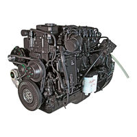
917 pages
ISB Service Manual
253 pages
NTA-855-L4 Maintenance And Operator’s Manual
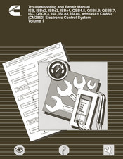
81 pages
ISB Troubleshooting And Repair Manual
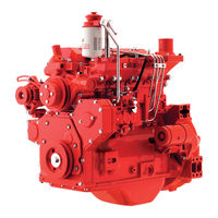
128 pages
B3.3 Service Manual
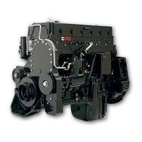
714 pages
K19 Series Troubleshooting And Repair Manual
51 pages
QSB6.7 Service Manual
693 pages
Big Cam III Troubleshooting And Repair Manual
741 pages
B3.9 Service Manual
77 pages
ISX15 600 Reference Manual
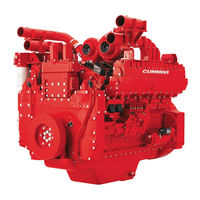
184 pages
QST30 Service Manual
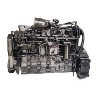
363 pages
QSC8.3 Operation And Maintenance Manual
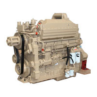
83 pages
NH 855 Shop Manual
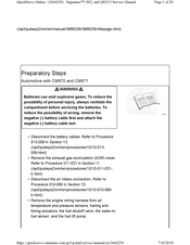
20 pages
Signature ISX Service Manual
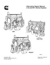
355 pages
L10 Series Repair Manual

116 pages
QSB4.5 Owner’s Manual
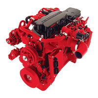
3 pages
ISB Series Quick Reference Manual
30 pages
Signature ISX Service Manual
209 pages
QSX15L Owner’s Manual
Models
Document Type
4
485ST

Reference Manual
4BT3.9
Shop Manual • Service Manual
5
5.9
Shop Manual
6
6BT5.9
Shop Manual • Service Manual
6IRQ9AE
Operation And Maintenance Manual
B
B Series 1991
Shop Manual
B Series 1994
Shop Manual
B109
Troubleshooting Manual
B112
Troubleshooting Manual
B3.3
Service Manual
B3.9 Series
Service Manual • Installation Manual, Operation And Maintenance Manual
B4.5 RGT
Service Manual
B4.5 Series
Service Manual • Installation Manual, Operation And Maintenance Manual
B5.9 Series
Service Manual • Installation Manual, Operation And Maintenance Manual
Big Cam III
Troubleshooting And Repair Manual
Big Cam IV
Troubleshooting And Repair Manual
C
C100D6C
Operator’s Manual • Operator’s Manual
C125D6C
Operator’s Manual • Operator’s Manual
C50D6C
Operator’s Manual • Operator’s Manual
C60D6C
Operator’s Manual • Operator’s Manual
C80D6C
Operator’s Manual • Operator’s Manual
CELECT L10 Series
Shop Manual
CELECT M11
Troubleshooting And Repair Manual
CELECT Plus M11
Troubleshooting And Repair Manual
CFP11E SERIES
Operation & Maintenance Manual • Operation And Maintenance Manual • Operation And Maintenance Manual • Installation, Operation And Maintenance Manual
CFP15E Series
Operation & Maintenance Manual • Operation & Maintenance Manual • Installation, Operation And Maintenance Manual
CFP15E/EVS
Operation And Maintenance Manual
CFP23E Radiator-cooled Series
Operation And Maintenance Manual
CFP23E/EVS
Operation And Maintenance Manual
CFP30E
Operation And Maintenance Manual
CFP59 F10
Installation, Operation And Maintenance Manual
CFP59 F15
Installation, Operation And Maintenance Manual
CFP59 F20
Installation, Operation And Maintenance Manual
CFP59 F25
Installation, Operation And Maintenance Manual
CFP59 F40
Installation, Operation And Maintenance Manual
CFP59 F50
Installation, Operation And Maintenance Manual
CFP59 Series
Installation, Operation And Maintenance Manual
CFP5E Series
Installation, Operation And Maintenance Manual
CFP5E/EVS
Installation, Operation And Maintenance Manual
CFP60E
Installation, Operation And Maintenance Manual
CFP7E Series
Operation And Maintenance Manual • Operation And Maintenance Manual
CFP7E/EVS
Installation, Operation And Maintenance Manual
CFP7E/EVS F-10
Operation And Maintenance Manual • Operation And Maintenance Manual
CFP7E/EVS F-20
Operation And Maintenance Manual • Operation And Maintenance Manual
CFP7E/EVS F-30
Operation And Maintenance Manual • Operation And Maintenance Manual
CFP7E/EVS F-40
Operation And Maintenance Manual • Operation And Maintenance Manual
CFP7E/EVS F-50
Operation And Maintenance Manual • Operation And Maintenance Manual
CFP7E/EVS F-60
Operation And Maintenance Manual • Operation And Maintenance Manual
CFP83 SERIES
Operation & Maintenance Manual
CFP83-F10
Operation & Maintenance Manual • Installation, Operation And Maintenance Manual
CFP83-F20
Operation & Maintenance Manual • Installation, Operation And Maintenance Manual
CFP83-F30
Operation & Maintenance Manual • Installation, Operation And Maintenance Manual
CFP83-F40
Operation & Maintenance Manual
CFP9E HHP Series
Operation And Maintenance Manual • Installation, Operation And Maintenance Manual
CFP9E SERIES
Operation And Maintenance Manual • Operation & Maintenance Manual
CFP9E/EVS
Installation, Operation And Maintenance Manual
CM2150
Troubleshooting Manual
CM2350
Service Manual • Troubleshooting Manual
CM850
Troubleshooting And Repair Manual
F
Fire Power CFP50
Manual
Fire Power CFP50-F10
Manual
Fire Power CFP50-F20
Manual
Fire Power CFP50-F30
Manual
Fire Power CFP50-F40
Manual
Fire Pump Drive Engines
Operation & Maintenance Manual
FIxed Time L10 Series
Shop Manual
Formula L10-240
Troubleshooting And Repair Manual
Formula L10-270
Troubleshooting And Repair Manual
Formula L10-300
Troubleshooting And Repair Manual
Formula LTA10B-270
Troubleshooting And Repair Manual
I
ISB
Operation And Maintenance Manual • Service Manual • Troubleshooting And Repair Manual
ISB 300
Quick Start Manual
ISB Series
Quick Reference Manual
ISB6.7 CM2350 B101
Quick Reference Manual • Service Manual
ISBE
Service Manual
ISBe2
Troubleshooting And Repair Manual
ISBe3
Troubleshooting And Repair Manual
ISBe4
Troubleshooting And Repair Manual
ISC
Troubleshooting And Repair Manual
ISL
Troubleshooting And Repair Manual
ISL G 250
Reference Manual
ISL G 260
Reference Manual
ISL G 280
Reference Manual
ISL G 300
Reference Manual
ISL G 320
Reference Manual
ISLe3
Troubleshooting And Repair Manual
ISLe4
Troubleshooting And Repair Manual
ISM
Servicing
ISX11.9
Servicing • Manual
ISX12
Manual
ISX12 310
Reference Manual
ISX12 320V
Reference Manual
ISX12 330
Reference Manual
ISX12 330ST
Reference Manual
ISX12 350
Reference Manual
ISX12 350ST
Reference Manual
ISX12 350V
Reference Manual
ISX12 370
Reference Manual
ISX12 385V
Reference Manual
ISX12 400
Reference Manual
ISX12 400ST
Reference Manual
ISX12 400V
Reference Manual
ISX12 425
Reference Manual
ISX12 425ST
Reference Manual
ISX12 425V
Reference Manual
ISX12 450 Series
Reference Manual
ISX12 500 Series
Reference Manual
ISX12 G 320
Reference Manual
ISX12 G 330
Reference Manual
ISX12 G 350
Reference Manual
ISX12 G 385
Reference Manual
ISX12 G 400
Reference Manual
ISX15
Reference Manual • Owner’s Manual • Service Manual
ISX15 400
Reference Manual
ISX15 400ST
Reference Manual
ISX15 425
Reference Manual
ISX15 425ST
Reference Manual
ISX15 450
Reference Manual
ISX15 450ST
Reference Manual
ISX15 455
Reference Manual
ISX15 455V
Reference Manual
ISX15 485
Reference Manual
ISX15 500
Reference Manual
ISX15 500ST
Reference Manual
ISX15 500V
Reference Manual
ISX15 525
Reference Manual
ISX15 550
Reference Manual
ISX15 600
Reference Manual
K
K19 Series
Troubleshooting And Repair Manual
KTA19
Troubleshooting And Repair Manual
KTTA19
Troubleshooting And Repair Manual
L
L10 Series
Repair Manual • Troubleshooting And Repair Manual
L10-300F
Troubleshooting And Repair Manual
L10-320
Troubleshooting And Repair Manual
L11 Series
Repair Manual
LT10-A
Troubleshooting And Repair Manual
LT10-C
Troubleshooting And Repair Manual
LTA10-C
Troubleshooting And Repair Manual
M
M11 Series
Shop Manual • Troubleshooting And Repair Manual
MDKAA
Installation Manual
MDKAB
Installation Manual
MDKAL
Installation Manual
MerCruiser QSD 2.8
Manual
MerCruiser QSD 4.2
Manual
N
N14
Shop Manual • Troubleshooting And Repair Manual
N14 Celect Plus
Shop Manual
N14330E
Shop Manual
NH 855
Shop Manual
NH-250
Operation And Maintenance Manual
NT 855
Shop Manual • Troubleshooting And Repair Manual
NT-335
Operation And Maintenance Manual
NT-380
Operation And Maintenance Manual
NTA-855-L4
Maintenance And Operator’s Manual
NTC-475
Troubleshooting And Repair Manual
P
Power Torque L10-240
Troubleshooting And Repair Manual
Power Torque L10-250
Troubleshooting And Repair Manual
Power Torque L10-270
Troubleshooting And Repair Manual
Power Torque L10-285
Troubleshooting And Repair Manual
Power Torque LTA10B-240
Troubleshooting And Repair Manual
Power Torque LTA10B-270
Troubleshooting And Repair Manual
Power Torque LTA10B-320
Troubleshooting And Repair Manual
Q
QSB
Service Manual
QSB4.5 CM2350 B106
Owner’s Manual • Owner’s Manual • Troubleshooting And Repair Manual
QSB5-G13
Operator’s Manual • Operator’s Manual
QSB5-G5
Operator’s Manual • Operator’s Manual
QSB5-G6
Operator’s Manual • Operator’s Manual
QSB5.9
Troubleshooting And Repair Manual
QSB6.7 CM2250 EC
Owner’s Manual • Owner’s Manual • Troubleshooting And Repair Manual • Service Manual • Troubleshooting Manual • Troubleshooting Manual • Owner’s Manual
QSB6.7 CM2350 B105
Owner’s Manual
QSC8.3
Operation And Maintenance Manual • Troubleshooting And Repair Manual • Owner’s Manual
QSD 2.8 Sterndrive 170 HP
Service Manual
QSD 2.8 Sterndrive 200 HP
Service Manual
QSD 2.8 Sterndrive 230 HP
Service Manual
QSD 4.2 Sterndrive 270 HP
Service Manual
QSD 4.2 Sterndrive 320 HP
Service Manual
QSD 4.2 Sterndrive 350 HP
Service Manual
QSK19
Troubleshooting And Repair Manual • Shop Manual • Troubleshooting And Repair Manual
QSK23 Series
Installation And Mounting Manual
QSK45
Manual
QSL9
Operation And Maintenance Manual • Troubleshooting And Repair Manual • Service Manual • Owner’s Manual
QST30
Service Manual
QSX15 CM2350 X105
Owner’s Manual
QSX15L
Owner’s Manual
QUANTUM K19 Series
Troubleshooting And Repair Manual
R
R2.8 CM2220 R101B
Installation Manual
S
S3.8
Workshop Manual
Signature ISX
Service Manual • Service Manual
Signature QSX15
Service Manual • Service Manual
STC L10 Series
Shop Manual
STC M11
Troubleshooting And Repair Manual
STC N14
Shop Manual • Troubleshooting And Repair Manual
V
V-504
Operation And Maintenance Manual
V-555
Operation And Maintenance Manual
V-903
Operation And Maintenance Manual
V12-500
Operation And Maintenance Manual
V8-300
Operation And Maintenance Manual
VT12-635
Operation And Maintenance Manual
VT12-700
Operation And Maintenance Manual
VT12-800
Operation And Maintenance Manual
VT8-370
Operation And Maintenance Manual
Руководство по ремонту (4960496)
Двигатели серии ISBe, ISB и QSB
(топливная система с общим топливопроводом высокого давления)
Двигатели серии 4ISBe /6ISBe
Предлагаем к вашему вниманию руководство по ремонту двигателя Cummins ISBE/QSB серии
Лот состоит из 2 частей и включает в себя в электронном виде: 1)Руководство по ремонту двигателей серии ISB, ISBe, ISBe4, QSB4.5, QSB5.9 и QSB6.7 (топливная система с общим топливопроводом высокого давления) (4960496)

2) Руководство по диагностике неисправностей и ремонту электронной системы управления двигателей CUMMINS(PACCAR)ISB (4-цилиндровых) и ISBe (4- и 6-цилиндровых) (4960589)
Руководство по ремонту 6ISBE
⇑⇑⇑⇑⇑
Запчасти
Двигатели Cummins, Запчасти, Корейские запчасти, Двигатель, Автобус, Экскаватор, Спецтехника, Hyundai Robex, Daewoo-Doosan, Volvo, Samsung MX, MX132, MX202, MX8, MX6, Robex1300, Robex130, Robex2000, Cummins b3.9, Cummins 4BT, Cummins b5.9, Cummins 6BT, Cummins isf2.8, Cummins isf3.8, Cummins 4isbe, Cummins 6isbe, Cummins M11, Cummins KTA19, Cummins qsb6.7, Cummins EQB5.9, Cummins 6isl8.9, Cummins NT855, Cummins LTA10, Грузовик, Автозапчасти, МКПП, Коробка передач, Раздатка, Прокладка, Стартер, Двигатель, Запчасти, Карданный вал, Мост, Редуктор, Поршня, Гильза, Кольца, Коленвал, Шатун, Гидроцилиндр, ТНВД, Форсунка, Радиатор, Сальник, Амортизатор, Фильтр, Топливный, Масляный, Воздушный, Коронки, Зубы, Ремкомплект, ДВС, Насос, ГУР, Подрезы, Выжимной, Подшипник, Корзина, Сцепления, Диск, Сцепление, Коробка Передач, Поршень, Средний, мост, Шкворень, Шкворня, Сайлентблок, Сальник, Рулевая, Колонка, Кардан, Амортизатор, Рессора, Рессорный Лист, Поросёнок, Вкладыши, Коренные, Шатунные, Турбина, Компрессор, ПГУ, Подушка, Палец, МКПП, Тормоз, Ступица, Шестерня, Колодки, Тормозные, Накладка, Hyndai, Daewoo, Samsung, Doosan, Cosmos, KIA, Aero City, Aero Space, GRANBIRD, GRANTO, Aero Town, Transtar, ULTRA, Самсунг, ASIA, AM 937, Хундай, L6, L7, LX, ДЭУ, Гранбёрд, КИЯ, Аэротаун, АэроСити, 6BT, 4BT, Корея, 6BT 5.9, Каминз, Каминс, Камминз, Cummins, Cumins, 4BT 3.9, EF750, F17E, D1146, DE12, dv15, DE08TIS, DV11, D6BR, D6AU, D6AV, H07C, D6AB, D6AC, D6CA, D6CB, D6DA, D2366, D8AY, D8AB, DC23, JT, VM39, Am 948, BS 106, BM 090, BH 115, BH 117, BH 120, D8AB
Срочная Доставка во все города России, Казахстана
Абакан, Алмата, Альметьевск, Армавир, Архангельск, Астрахань, Ачинск, Байкальск, Балаково, Барнаул, Белгород, Белогорск, Березники, Бийск, Биробиджан, Благовещенск, Бодайбо, Братск, Брянск, Великий Новгород, Вихоревка, Владивосток, Владимир, Волгоград, Волжский, Вологда, Воронеж, Глазов, Екатеринбург, Иваново, Ижевск, Иркутск, Йошкар-Ола, Железногорск-Илимский, Зима, Казань, Калуга, Канск, Кемерово, Киров, Комсомольск-на-Амуре, Кострома, Краснодар, Красноярск, Курган, Курск, Липецк, Магадан, Магистральный, Магнитогорск, Махачкала, Миасс, Москва, Мурманск, Набережные, Челны, Находка, Нерюнгри, Нефтекамск, Нижневартовск, Нижнеудинск, Нижний Новгород, Нижний Тагил, Новая Игирма, Новокузнецк, Новороссийск, Новосибирск, Новый Уренгой, Ноябрьск, Омск, Орел, Оренбург, Орск, Пенза, Пермь, Петрозаводск, Петропавловск-Камчатский, Псков, Пятигорск, Ростов-на-Дону, Рубцовск, Рязань, Самара, Санкт-Петербург, Саранск, Саратов, Саянск, Слюдянка, Смоленск, Сочи, Ставрополь, Стерлитамак, Сургут, Сыктывкар, Таганрог, Тайшеь, Тамбов, Тверь, Тольятти, Томск, Тула, Тулун, Тюмень, Улан-Удэ, Улькан, Ульяновск, Усть-Илимск, Усть-Кут, Уфа, Хабаровск, Ханты-Мансийск, Чайковский, Чебоксары, Челябинск, Черемхово, Череповец, Чита, Чунский, Южно-Сахалинск, Якутск, Ярославль, Алупка, Алушта, Армянск, Бахчисарай, Белогорск, Джанкой, Евпатория, Инкерман, Керчь, Красноперекопск, Саки, Севастополь, Симферополь, Старый Крым, Судак, Феодосия, Щёлкино, Ялта
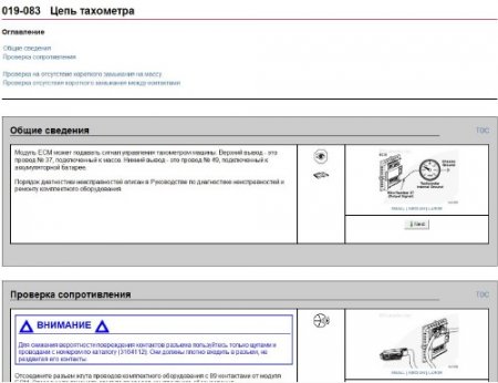
Материал содержит 2 книги: «Руководство по диагностике неисправностей и ремонту электронной системы управления двигателей CUMMINS (PACCAR) ISB (4-цилиндровых) и ISBe (4- и 6-цилиндровых)» и «Руководство по ремонту двигателей серии ISB, ISBe, ISBe4, QSB4.5, QSB5.9 и QSB6.7 (топливная система с общим топливопроводом высокого давления)» на русском языке.
Целью руководства является оказание помощи техническому персоналу при разборке, проверке возможности повторного использования, ремонту и сборке узлов двигателя. Описаны коды неисправностей, технические приспособления для ремонта двигателя.
Год выпуска: 2006 г.
Автор: CUMMINS
Издательство: © 2000-2010 Cummins Inc
Формат: CHM
Качество: Изначально компьютерное
Язык авто-книги : Русский
размер : 329 мб.
Скачать мануал Cummins серии ISB, ISBe, ISBe4, QSB4.5, QSB5.9, QSB6.7
Внимание! У Вас нет прав для просмотра скрытого текста.