- Manuals
- Brands
- CUMMINS Manuals
- Engine
- QSK23 Series
- Installation and mounting manual
-
Bookmarks
Quick Links
Бриз Моторс
T o ble hoo ing and Repai Man al
QSK23 Se ie Engine
CTM C.800 — Cummins (644 кВт)
http://www.brizmotors.ru/equipment/ctm/c800/
1/1
Related Manuals for CUMMINS QSK23 Series
Summary of Contents for CUMMINS QSK23 Series
-
Page 1
Бриз Моторс T o ble hoo ing and Repai Man al QSK23 Se ie Engine CTM C.800 — Cummins (644 кВт) http://www.brizmotors.ru/equipment/ctm/c800/… -
Page 2
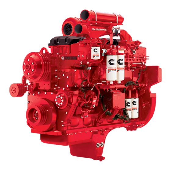
18/05/12 QuickServe Online | (4021375) QSK23 Troubleshooting and Repair Manual Vie Rela ed Topic 100002 Engine Diagrams Engine Views The ill a ion ho he loca ion of he majo e e nal engine componen , fil e , and o he e ice and main enance poin . Some e e nal componen ill be a diffe en loca ion fo diffe en engine model . -
Page 3
18/05/12 QuickServe Online | (4021375) QSK23 Troubleshooting and Repair Manual 7. Fuel timing suppl 8. Fuel pipe (to fuel rail) 9. Fuel pipe (return) 10. Fuel pipe (for injection timing) 11. Fuel rail suppl 12. Cam follower cover 13. OEM electrical connections (Industrial onl ) 14. Oil pressure checkpoint (after filters) 15. Oil pressure checkpoint (before filters) 16. Engine barring device 17. Oil filters 18. ECVA/ECM 19. Wiring harness 20. Oil fill port 21. Fuel rail dampening hose 22. -
Page 4
18/05/12 QuickServe Online | (4021375) QSK23 Troubleshooting and Repair Manual Lef Side Po e Gene a ion 1. In ake manifold (Po e Gene a ion onl ) 2. C ankca e b ea he 3. In ake manifold p e e en o (Po e Gene a ion onl ) 4. -
Page 5
18/05/12 QuickServe Online | (4021375) QSK23 Troubleshooting and Repair Manual 1. T bocha ge 2. E ha manifold (3piece) 3. Rocke le e co e 4. The mo a ho 5. Engine coolan o le 6. Coolan empe a e en o 7. -
Page 6
18/05/12 QuickServe Online | (4021375) QSK23 Troubleshooting and Repair Manual 9. Coolant filter head (Industrial onl ) 10. Fan hub assembl 11. Engine coolant outlet. Front View Industrial and Power Generation 1. Front engine lifting bracket 2. Alternator 3. Blowb tube 4. Cooling fan drive belt 5. Drive pulle (for alternator and refrigerant compressor) 6. Oil drain valve 7. Oil pan 8. Vibration damper 9. Front gear cover 10. Cooling fan belt tensioner (Industrial onl ) 11. -
Page 7
18/05/12 QuickServe Online | (4021375) QSK23 Troubleshooting and Repair Manual Rear View Industrial and Power Generation 1. Oil pressure checkpoint (after oil coolers) 2. Flywheel housing 3. Oil pan 4. Engine oil drain valve 5. Engine speed sensor (Industrial onl ) 6. OEM electrical connections (Industrial onl ). Last Modified: 08Jul2003 Copyright 20002010 Cummins Inc. All rights reserved. http://www.brizmotors.ru/equipment/ctm/c800/… -
Page 8
18/05/12 QuickServe Online | (4021375) QSK23 Troubleshooting and Repair Manual View Related Topic 001999 C linder Block Overview General Information The QSK23 c linder block is a robust design made of a onepiece iron casting. It has a solid and durable design to absorb internal forces and to enable resilient mounting. The onepiece iron block emplo s both front and rear gear housings. The oil pump housing and water jacket are also integrated into the c linder block. Crankshaft The QSK23 crankshaft is made of forged high tensile steel. Vibration Damper The QSK23 uses a viscous vibration damper mounted on the crankshaft nose. The vibration damper reduces the crankshaft torsional vibration and reduces gear train loading. C linder Liner The QSK23 uses a pressedin, removable, c linder liner. The liner has a 170 mm [6.69 in] bore and incorporates a top stop liner design. The top stop liner design features special honing for oil control and related piston ring wear. It also provides… -
Page 9
18/05/12 QuickServe Online | (4021375) QSK23 Troubleshooting and Repair Manual resistance to liner cavitation, and improvements to the cylinder head attachment joint due to low bending stress. Piston The QSK23 uses single piece ferrous cast ductile iron pistons. These pistons reduce pistontoliner clearance for improvements in oil consumption, and optimize liner ovality and thereby the likelihood of liner ringing . Cast iron is used for its high strength and superior durability. Camshaft The QSK23 camshaft measures 105 mm [4.13 in] in diameter. A big cam diameter was incorporated to drive high pressure unit injectors. A special surface treatment was applied on cam follower roller surfaces to maintain adequate lubrication. La Modified: 08J l2003 Copyright © 20002010 Cummins Inc. All rights reserved. http://www.brizmotors.ru/equipment/ctm/c800/… -
Page 10
18/05/12 QuickServe Online | (4021375) QSK23 Troubleshooting and Repair Manual R T 002999 C linder Head Overview General Information QSK23 . T . T … -
Page 11
18/05/12 QuickServe Online | (4021375) QSK23 Troubleshooting and Repair Manual La Modified: 08J l2003 Copyright 20002010 Cummins Inc. All rights reserved. http://www.brizmotors.ru/equipment/ctm/c800/… -
Page 12
18/05/12 QuickServe Online | (4021375) QSK23 Troubleshooting and Repair Manual View Related Topic 003999 Rocker Le ers O er ie General Information Rocker Lever Covers The QSK23 rocker lever covers are made of cast aluminum and utili e reusable o ring t pe valve cover gaskets. Injector Levers The QSK23 injector levers are made from forged steel. Rocker Levers Each QSK23 rocker lever is a single piece, solid design with a precisionground nose radius. Rocker Lever Shaft The QSK23 uses a large 45 mm [1.77 in] rocker lever shaft diameter due to high injector train loads. http://www.brizmotors.ru/equipment/ctm/c800/… -
Page 13
18/05/12 QuickServe Online | (4021375) QSK23 Troubleshooting and Repair Manual The valves and injectors are adjusted using the outer base circle (OBC) feeler gauge, or screwdriver method. La Modified: 08J l2003 Copyright 20002010 Cummins Inc. All rights reserved. http://www.brizmotors.ru/equipment/ctm/c800/… -
Page 14
QuickServe Online | (4021375) QSK23 Troubleshooting and Repair Manual View Related Topic 004999 Cam Follo e /Tappe O e ie Gene al Info ma ion A special surface treatment is applied to the QSK23 cam follower roller surfaces to maintain adequate lubrication. The cam follower, push tube, and rocker lever are optimized to keep rigidity during injection pressures, to reduce weight, and reduce the possibility of drive system no follow conditions. Cam follower roller pins are assembled using liquid nitrogen. Replacement rollers and pins are no available for service. If the roller fails, the entire cam follower roller assembly m be replaced. The cam follower rollers are microfinished and have a complex crown. The rollers m no be reground for service. La Modified: 08J l2003 Copyright 20002010 Cummins Inc. All rights reserved. http://www.brizmotors.ru/equipment/ctm/c800/… -
Page 15
18/05/12 QuickServe Online | (4021375) QSK23 Troubleshooting and Repair Manual View Related Topic 005999 Fuel S stem Overview General Information Fuel System The QSK23 engine is equipped with the Quantum fuel system. The Quantum fuel system provides full electronic control of the engine with highpressure fuel injection. Operation The QSK23 fuel pump supplies regulated pressure to the control valve assembly for the rail and timing as a function of speed. The fuel is supplied to both the rail and timing actuators. The actuators act as throttles to control the amount of fuel metered to the injector and timing supply lines. Timing and rail pressure sensors, after the actuators, measure the actual supplied pressures. The ECM compares the actual supplied pressures to the desired supply pressures. Desired supply pressure is based on throttle position and speed inputs. The ECM then communicates to the actuator to change spool plunger position which changes the flow orifice area until the desired pressures are obtained. Fuel Filter http://www.brizmotors.ru/equipment/ctm/c800/… -
Page 16
18/05/12 QuickServe Online | (4021375) QSK23 Troubleshooting and Repair Manual The QSK23 requires two 10micron fuel filters with water separators, Fleetguard Part Number FS1006, to provide injector and control valve protection. Fuel Pump The QSK23 has an electronically controlled fuel pump that regulates output pressure to specific values based on a given engine speed. The pump has a fuel bypass regulator circuit controlled by an actuator. The actuator receives its command from the ECM based on the pump pressure sensor and the engine speed sensor. The QSK23 fuel pump is very similar to the pump used on QSK45, QSK60, and QSK78 series engines. Electronic Control Valve Assembly (ECVA) The electronic control valve assembly is located on the fuel pump side of the engine. The assembly contains the following actuators and sensors: 1. Timing rail pressure sensor 2. Fuel rail pressure sensor 3. Barometric pressure sensor 4. Fuel rail actuator 5. -
Page 17
18/05/12 QuickServe Online | (4021375) QSK23 Troubleshooting and Repair Manual La Modified: 08J l2003 Copyright 20002010 Cummins Inc. All rights reserved. http://www.brizmotors.ru/equipment/ctm/c800/… -
Page 18
18/05/12 QuickServe Online | (4021375) QSK23 Troubleshooting and Repair Manual 200001 Flow Diagram, Fuel S stem Fuel S stem 1. Fuel inlet from tank 2. Fuel filters with water separation 3. Fuel pump inlet tube 4. Fuel pump 5. Fuel control valve suppl tube 6. Fuel timing suppl tube 7. Fuel rail suppl tube 8. Fuel rail dampening hose 9. Electronic fuel control valve assembl 10. Injector 11. Fuel return tube 12. Fuel drain (engine to fuel tank) http://www.brizmotors.ru/equipment/ctm/c800/… -
Page 19
18/05/12 QuickServe Online | (4021375) QSK23 Troubleshooting and Repair Manual 13. ECM. 1. Fuel inlet from pump 2. Fuel timing actuator 3. Fuel temperature sensor 4. Fuel shutoff valve 5. Fuel rail actuator 6. Fuel rail dampening hose 7. Fuel to fuel rail 8. Fuel to fuel timing. La Modified: 17Ma 2003 Copyright 20002010 Cummins Inc. All rights reserved. http://www.brizmotors.ru/equipment/ctm/c800/… -
Page 20
18/05/12 QuickServe Online | (4021375) QSK23 Troubleshooting and Repair Manual View Related Topic 006999 Injec o and F el Line O e ie Gene al Info ma ion Fuel Tubes The QSK23 fuel rail supply (1), timing rail supply (2), and fuel drain (3) are integrated into the intake manifold housing. Fuel supply and drain lines are sized to provide sufficient flow for injection and timing functions. Straight thread face oring fittings are used for superior leak prevention. The recommended fuel pump inlet line size provides a maximum clean filter restriction of 102 mm Hg [4 in Hg] at high idleno load. The fuel drain fitting provides a maximum drain line restriction of 203 mm Hg [8 in Hg]. The fuel temperature at the fuel pump inlet no exceed 71 C [160 F]. A fuel cooler in the fuel drain circuit will possibly be required. The fuel cooler is to be provided by the original equipment… -
Page 21
18/05/12 QuickServe Online | (4021375) QSK23 Troubleshooting and Repair Manual The fuel rails in the intake manifold receive fuel from the Electronic Control Valve Actuator (ECVA) through a fuel rail supply tube (1) and fuel timing supply tube (2). The fuel then passes through the fuel rails, through the cylinder head, and into the injectors. Unused fuel flows back through the cylinder head, into the fuel rail, and out through the fuel drain fitting (3) to return to the fuel tank. Industrial applications with dual intake manifolds will have a steel return line connecting the two manifolds to the fuel drain fitting. Quantum Injector The QSK23 Quantum injector begins operation with metering. The lower plunger retracts during the inner base circle portion of the camshaft profile, thus uncovering the rail feed port. The fuel is Pressure Time (PT) metered into the nozzle. The amount metered is a function of rail pressure and engine speed. This supply pressure will be as high as 1379 kPa [200 psi] at maximum fueling/speed and as low as 13.8 kPa [2 psi] at idle. The timing fuel is also PT metered through a separate metering port into a chamber between the upper and timing plungers in the barrel. This also occurs during the inner base circle portion of the camshaft… -
Page 22
18/05/12 QuickServe Online | (4021375) QSK23 Troubleshooting and Repair Manual The amount of fuel metered into the timing chamber determines the amount of separation of the upper and timing plungers. This separation amount, called overtravel, varies from an approximate minimum of 2 mm [0.078 in] at torque peak fueling to a maximum of 9 mm [0.354 in] at high idle fueling. The amount of overtravel is changed to vary the start of injection for all speed and fueling conditions. La Modified: 08J l2003 Copyright 20002010 Cummins Inc. All rights reserved. http://www.brizmotors.ru/equipment/ctm/c800/… -
Page 23
QuickServe Online | (4021375) QSK23 Troubleshooting and Repair Manual View Related Topic 007999 Lubricating Oil S stem Overview General Information The QSK23 engine has two spinon lubricating filter canisters. These filters can be replaced with Fleetguard media with a wire mesh backing to obtain 10micron filtering capability and long life. The venturi combo filter design provides for both fullflow and bypass lubricating oil filtration in the same canister, eliminating the requirement for bypass filters. The filters are onl mounted on the left side (fuel pump side) of the engine. Cummins Inc. recommends using Fleetguard venturi combo filters, Part Number LF9325, at each oil change interval. The QSK23 uses an oil pump idler gear which drives the lubricating oil pump at the front of the engine. The QSK23 highpressure relief valve is located internally in the lubricating oil pump. The relief pressure is 883 kPa [128 psi]. The highpressure relief valve also serves http://www.brizmotors.ru/equipment/ctm/c800/… -
Page 24
18/05/12 QuickServe Online | (4021375) QSK23 Troubleshooting and Repair Manual as the primary oil pressure regulator located internal to the lubricating oil pump. Regulated oil rifle pressure is 393 to 552 kPa [57 to 80 psi] at rated rpm. The QSK23 uses two oil coolers in parallel. Each cooler housing contains a thermostat which begin opening at 85°C [185°F] and fully open at 100°C [212°F]. Lubricating oil is routed from the oil pump through the oil coolers, across the rear of the engine, and to the oil filters. The oil then flows to the main oil gallery which supplies oil to the crankshaft, rod bearings, piston cooling nozzle gallery, camshaft, front and rear gear train, and turbocharger. There are multiple oil pressure ports for OEM usage. La Modified: 08J l2003 Copyright 20002010 Cummins Inc. All rights reserved. http://www.brizmotors.ru/equipment/ctm/c800/… -
Page 25
18/05/12 QuickServe Online | (4021375) QSK23 Troubleshooting and Repair Manual 200002 Flow Diagram, Lubricating Oil S stem Flow Diagram 1. L b ica ing oil pan 2. L b ica ing oil c ion be 3. L b ica ing oil p mp 4. L b ica ing oil p e e eg la o al e 5. -
Page 26
18/05/12 QuickServe Online | (4021375) QSK23 Troubleshooting and Repair Manual 1. Lubricating oil flow from oil coolers 2. Lubricating oil flow to filters 3. Lubricating oil filter b pass valve(s) 4. Lubricating oil filter(s) 5. Lubricating oil from filters 6. Main lubricating oil rifle 7. Lubricating oil flow to c linder head 8. Lubricating oil flow to rear idler gear 9. Normal lubricating oil flow through filter 10. B pass lubricating oil flow. http://www.brizmotors.ru/equipment/ctm/c800/… -
Page 27
18/05/12 QuickServe Online | (4021375) QSK23 Troubleshooting and Repair Manual 1. Lubricating oil flow from filters 2. Main lubricating oil rifle 3. Lubricating oil drilling to turbocharger suppl 4. Lubricating oil drilling to piston cooling no le oil rifle 5. Lubricating oil flow to camshaft bushings and c linder head 6. Lubricating oil flow to main bearings and crankshaft 7. Lubricating oil flow to front idler gears 8. Lubricating oil flow to piston cooling no les 9. Turbocharger oil suppl tube 10. Turbocharger oil drain to crankcase. http://www.brizmotors.ru/equipment/ctm/c800/… -
Page 28
18/05/12 QuickServe Online | (4021375) QSK23 Troubleshooting and Repair Manual 1. Pi on pin b hing 2. Connec ing od 3. C ank haf . http://www.brizmotors.ru/equipment/ctm/c800/… -
Page 29
18/05/12 QuickServe Online | (4021375) QSK23 Troubleshooting and Repair Manual 1. Lubricating oil flow through cylinder head 2. Lubricating oil flow through rocker housing 3. Lubricating oil flow around rocker shaft capscrew and through rocker shaft 4. Lubricating oil flow through rocker levers 5. Lubricating oil flow through injector lever 6. Lubricating oil return to pan. La Modified: 17Ma 2003 Copyright 20002010 Cummins Inc. All rights reserved. http://www.brizmotors.ru/equipment/ctm/c800/… -
Page 30
18/05/12 QuickServe Online | (4021375) QSK23 Troubleshooting and Repair Manual 200004 Flow Diagram, Air Intake S stem Air Intake S stem 1. Intake air inlet to turbocharger 2. Turbocharged air to charge air cooler 3. Charge air cooler 4. Intake manifold 5. Grid heater (Industrial onl ) 6. C linder head intake air port 7. Intake valve. Last Modified: 17Mar2003 http://www.brizmotors.ru/equipment/ctm/c800/… -
Page 31
18/05/12 QuickServe Online | (4021375) QSK23 Troubleshooting and Repair Manual Copyright 20002010 Cummins Inc. All rights reserved. http://www.brizmotors.ru/equipment/ctm/c800/… -
Page 32
18/05/12 QuickServe Online | (4021375) QSK23 Troubleshooting and Repair Manual View Related Topic 010999 Air Intake S stem Overview General Information The QSK23 air intake system uses a remote charge air cooler to reduce the air temperature into the intake manifold. The charge air from the engine turbocharger is routed to the intake manifold by means of a radiator mounted (airtoair) cooler rather than through the conventional integral engine mounted aftercooler core (airto coolant) design. The advantage of cooling charge air directly by ambient air is that the lowest practical charge air temperature can be attained with the minimum cost penalty. The QSK23 engine uses a single high efficiency Holset HX82 singlestage turbocharger on the power generator application and a Schwitzer S500 turbocharger on the industrial application. The QSK23 turbocharger is mounted on the right side of the engine. http://www.brizmotors.ru/equipment/ctm/c800/… -
Page 33
18/05/12 QuickServe Online | (4021375) QSK23 Troubleshooting and Repair Manual La Modified: 08J l2003 Copyright 20002010 Cummins Inc. All rights reserved. http://www.brizmotors.ru/equipment/ctm/c800/… -
Page 34
QuickServe Online | (4021375) QSK23 Troubleshooting and Repair Manual 009999 D i e Uni O e ie Gene al Info ma ion The Drive Units section consists of the removal, inspection, and installation of the alternator drive gear and shaft. The alternator drive gear and shaft also drives the fuel pump and an OEM supplied refrigerant compressor on some industrial applications. The fuel pump engages the drive gear via a spider gear from the rear of the front cover and is mounted to the block. The alternator drive gear and shaft revolves at a 1:1 ratio to the crankshaft and in the same direction. The drive contains 55 teeth and is driven by the crank gear through an idler gear and is splash lubricated. La Modified: 04A g2003 Copyright 20002010 Cummins Inc. All rights reserved. http://www.brizmotors.ru/equipment/ctm/c800/… -
Page 35
18/05/12 QuickServe Online | (4021375) QSK23 Troubleshooting and Repair Manual 200003 Flow Diagram, Cooling S stem Cooling S stem 1. Coolant inlet from radiator 2. Water pump 3. Coolant flow through lubricating oil cooler 4. Coolant flow around c linder liners 5. Coolant flow to c linder head 6. Coolant flow from c linder head to coolant manifold 7. Coolant manifold to thermostat housing 8. Coolant filter suppl and return tubes http://www.brizmotors.ru/equipment/ctm/c800/… -
Page 36
18/05/12 QuickServe Online | (4021375) QSK23 Troubleshooting and Repair Manual 9. Coolant filter. 1. Coolant flow to cylinder head (four ports per cylinder head) 2. Coolant flow to water manifold (one port per cylinder head) 3. Coolant flow to thermostat housing 4. Radiator bypass open 5. Coolant flow to water pump 6. Coolant flow to oil coolers 7. Radiator bypass closed 8. Coolant flow to radiator 9. Coolant flow for optional torque converter (normally plugged) La Modified: 17Ma 2003 Copyright 20002010 Cummins Inc. All rights reserved. http://www.brizmotors.ru/equipment/ctm/c800/… -
Page 37
18/05/12 QuickServe Online | (4021375) QSK23 Troubleshooting and Repair Manual Vie Rela ed Topic 008999 Cooling S stem Overview General Information Cooling S The QSK23 engine e a anda d jacke a e cooling em fo he engine. Each head ha fo coolan inle po and one coolan o le po . The e i al o a coolan en po a … -
Page 38
18/05/12 QuickServe Online | (4021375) QSK23 Troubleshooting and Repair Manual La Modified: 08J l2003 Copyright 20002010 Cummins Inc. All rights reserved. http://www.brizmotors.ru/equipment/ctm/c800/… -
Page 39
18/05/12 QuickServe Online | (4021375) QSK23 Troubleshooting and Repair Manual 200003 Flow Diagram, Cooling S stem Cooling S stem 1. Coolant inlet from radiator 2. Water pump 3. Coolant flow through lubricating oil cooler 4. Coolant flow around c linder liners 5. Coolant flow to c linder head 6. Coolant flow from c linder head to coolant manifold 7. Coolant manifold to thermostat housing 8. Coolant filter suppl and return tubes http://www.brizmotors.ru/equipment/ctm/c800/… -
Page 40
18/05/12 QuickServe Online | (4021375) QSK23 Troubleshooting and Repair Manual 9. Coolant filter. 1. Coolant flow to cylinder head (four ports per cylinder head) 2. Coolant flow to water manifold (one port per cylinder head) 3. Coolant flow to thermostat housing 4. Radiator bypass open 5. Coolant flow to water pump 6. Coolant flow to oil coolers 7. Radiator bypass closed 8. Coolant flow to radiator 9. Coolant flow for optional torque converter (normally plugged) La Modified: 17Ma 2003 Copyright 20002010 Cummins Inc. All rights reserved. http://www.brizmotors.ru/equipment/ctm/c800/… -
Page 41
QuickServe Online | (4021375) QSK23 Troubleshooting and Repair Manual 009999 D i e Uni O e ie Gene al Info ma ion The Drive Units section consists of the removal, inspection, and installation of the alternator drive gear and shaft. The alternator drive gear and shaft also drives the fuel pump and an OEM supplied refrigerant compressor on some industrial applications. The fuel pump engages the drive gear via a spider gear from the rear of the front cover and is mounted to the block. The alternator drive gear and shaft revolves at a 1:1 ratio to the crankshaft and in the same direction. The drive contains 55 teeth and is driven by the crank gear through an idler gear and is splash lubricated. La Modified: 04A g2003 Copyright 20002010 Cummins Inc. All rights reserved. http://www.brizmotors.ru/equipment/ctm/c800/… -
Page 42
18/05/12 QuickServe Online | (4021375) QSK23 Troubleshooting and Repair Manual View Related Topic 010999 Air Intake S stem Overview General Information The QSK23 air intake system uses a remote charge air cooler to reduce the air temperature into the intake manifold. The charge air from the engine turbocharger is routed to the intake manifold by means of a radiator mounted (airtoair) cooler rather than through the conventional integral engine mounted aftercooler core (airto coolant) design. The advantage of cooling charge air directly by ambient air is that the lowest practical charge air temperature can be attained with the minimum cost penalty. The QSK23 engine uses a single high efficiency Holset HX82 singlestage turbocharger on the power generator application and a Schwitzer S500 turbocharger on the industrial application. The QSK23 turbocharger is mounted on the right side of the engine. http://www.brizmotors.ru/equipment/ctm/c800/… -
Page 43
18/05/12 QuickServe Online | (4021375) QSK23 Troubleshooting and Repair Manual La Modified: 08J l2003 Copyright 20002010 Cummins Inc. All rights reserved. http://www.brizmotors.ru/equipment/ctm/c800/… -
Page 44
18/05/12 QuickServe Online | (4021375) QSK23 Troubleshooting and Repair Manual 200004 Flow Diagram, Air Intake S stem Air Intake S stem 1. Intake air inlet to turbocharger 2. Turbocharged air to charge air cooler 3. Charge air cooler 4. Intake manifold 5. Grid heater (Industrial onl ) 6. C linder head intake air port 7. Intake valve. Last Modified: 17Mar2003 http://www.brizmotors.ru/equipment/ctm/c800/… -
Page 45
18/05/12 QuickServe Online | (4021375) QSK23 Troubleshooting and Repair Manual Copyright 20002010 Cummins Inc. All rights reserved. http://www.brizmotors.ru/equipment/ctm/c800/… -
Page 46
18/05/12 QuickServe Online | (4021375) QSK23 Troubleshooting and Repair Manual View Related Topic 011999 E ha S em O e ie Gene al Info ma ion The QSK23 exhaust manifold has been aerodynamically designed to reduce pumping losses and to enhance pulse flow. In addition, the manifold connection has been designed to allow for thermal expansion. The maximum allowable exhaust system back pressure for the QSK23 engine is 76.2 mm Hg [3 in Hg]. La Modified: 08J l2003 Copyright 20002010 Cummins Inc. All rights reserved. http://www.brizmotors.ru/equipment/ctm/c800/… -
Page 47
18/05/12 QuickServe Online | (4021375) QSK23 Troubleshooting and Repair Manual 200005 Flo Diagram, E haust S stem E haust S stem 1. Cylinder head exhaust port 2. Exhaust manifold 3. Turbocharger exhaust outlet. Last Modified: 17Mar2003 Copyright 20002010 Cummins Inc. All rights reserved. http://www.brizmotors.ru/equipment/ctm/c800/… -
Page 48
18/05/12 QuickServe Online | (4021375) QSK23 Troubleshooting and Repair Manual 013999 E ec ica E e O e ie Ge e a I f The basic heav dut electrical s stem consists of: Batteries (1)(Usuall two or four connected in parallel) Starting motor (2) Alternator (3) Magnetic switch (4) Ignition switch (5) Necessar wiring ( shown) All components be carefull matched. -
Page 49
18/05/12 QuickServe Online | (4021375) QSK23 Troubleshooting and Repair Manual La Modified: 04A g2003 Copyright 20002010 Cummins Inc. All rights reserved. http://www.brizmotors.ru/equipment/ctm/c800/… -
Page 50
QuickServe Online | (4021375) QSK23 Troubleshooting and Repair Manual View Related Topic 016999 Mo n ing Adap a ion O e ie Gene al Info ma ion The QSK23 is available with a SAE 0 or SAE 1 flywheel/flywheel housing combination. The SAE 0 flywheel has a ring gear count of 138 teeth. The SAE 1 flywheel ring gear has 118 teeth. Tapped holes for transmission mounting are: 24 7/1614 UNC2B for SAE number 1 flywheel housing 16 M12 x 1.75 for SAE number 0 flywheel housing. The flywheel housing has two magnetic pickup locations. A magnetic pickup hole is currently dedicated for use by the electronic engine control system. The magnetic pickup hole available for customer use is M22 x 1.5. La Modified: 08J l2003 Copyright 20002010 Cummins Inc. All rights reserved. http://www.brizmotors.ru/equipment/ctm/c800/… -
Page 51
QuickServe Online | (4021375) QSK23 Troubleshooting and Repair Manual 00001 T o ble hoo ing P oced e and Techni Gene al Info ma ion A thorough analysis of the customer’s complaint is the key to successful troubleshooting. The more information known about a complaint, the faster and easier the problem can be solved. The Troubleshooting Symptom Charts are organized so that a problem can be located and corrected by doing the easiest and most logical things first. Complete all steps in the sequence shown from top to bottom. It is no possible to include all the solutions to problems that can occur; however, these charts are designed to stimulate a thought process that will lead to the cause and correction of the problem. Follow these basic troubleshooting steps: Get all the facts concerning the complaint Analyze the problem thoroughly Relate the symptoms to the basic engine systems and components Consider any recent maintenance or repair action that can relate to the complaint Doublecheck before beginning any disassembly Solve the problem by using the symptom charts and doing the easiest things first Determine the cause of the problem and make a thorough repair After repairs have been made, operate the engine to make sure the cause of the complaint has been corrected La Modified: 17No 2010 Copyright 20002010 Cummins Inc. All rights reserved. http://www.brizmotors.ru/equipment/ctm/c800/… -
Page 52
18/05/12 QuickServe Online | (4021375) QSK23 Troubleshooting and Repair Manual t00002 Troubleshooting S mptoms Charts General Information Use the charts on the following pages of this section to aid in diagnosing specific engine symptoms. Read each row of blocks from top to bottom. Follow through the chart to identify the corrective action. WARNING Troubleshooting presents the risk of equipment damage, personal injury or death. Troubleshooting must be performed by trained, experienced technicians. Last Modified: 03Apr2002 Copyright 20002010 Cummins Inc. All rights reserved. http://www.brizmotors.ru/equipment/ctm/c800/… -
Page 53
18/05/12 QuickServe Online | (4021375) QSK23 Troubleshooting and Repair Manual Vie Rela ed Topic 00004 Engine Noi e Diagno ic P oced e Gene al Info ma ion When diagno ing engine noi e p oblem , make e ha noi e ca ed b acce o ie , ch a he ai comp e o and po e … -
Page 54
18/05/12 QuickServe Online | (4021375) QSK23 Troubleshooting and Repair Manual E N E P I , , . A … -
Page 55
18/05/12 QuickServe Online | (4021375) QSK23 Troubleshooting and Repair Manual See he e f a ce ee E gi e Acce e a i Re e P f he e ced e ca e a d c ec a acce e a i … -
Page 56
18/05/12 QuickServe Online | (4021375) QSK23 Troubleshooting and Repair Manual If 6 7 a a e ed Ye , fi he D i eabi i /L P e / E ce i e F e C Chec i a d g A B C D E F Addi i a C ___________________________________________________________________________________________________ ___________________________________________________________________________________________________… -
Page 57
18/05/12 QuickServe Online | (4021375) QSK23 Troubleshooting and Repair Manual Additional Comments: ___________________________________________________________________________________________________ ___________________________________________________________________________________________________ This checklist can be copied for convenience. Fuel Consumption General Information The cause of excessive fuel consumption is hard to diagnose and correct because of the potential number of factors involved. Actual fuel consumption problems can be caused by any of the following factors: Engine factors Vehicle factors and specifications Environmental factors Driver technique and operating practices Fuel system factors Low power/driveability problems. Before troubleshooting, it is important to determine the exact complaint. Is the complaint based on whether the problem is real or perceived, or does not meet driver expectations? The Fuel Consumption — Customer Complaint Form is a valuable list of questions that can be used to assist the service technician in determining the cause of the problem. Complete the form before troubleshooting the complaint. The following are some of the factors that must be considered when troubleshooting fuel consumption complaints. 1. Result of a Low Power/Driveability Problem: An operator will change driving style to compensate for a low power/driveability problem. Some things the driver is likely to do are, (a) shift to a higher engine rpm or (b) run on the droop curve in a lower gear instead of upshifting to drive at part throttle conditions. These changes in driving style will increase the amount of fuel used. 2. Driver Technique and Operating Practices: As a general rule, a 1 mph increase in road speed equals a 0.16 km [0.1 mpg] increase in fuel consumption. This means that increasing road speed from 50 to 60 mph will result in a loss of fuel mileage of 1.6 km [1 mpg]. 3. Environmental and Seasonal Weather Changes: As a general rule, there can be as much as a 1.6 to 2.4 km [1 to 1.5 mpg] difference in fuel consumption depending on the season and the weather conditions. -
Page 58
13. What is the altitude during operation? Below 10,000 feet ________, Above 10,000 feet ________ 14. How much of the time is the truck spent idling? Hours/day __________ 15. Is the driver technique or operating practices affecting fuel economy? High road speed: mph __________ Operate at rated speed or above: rpm __________ Incorrect shift rpm: Shift rpm __________, Torque Peak __________ Operate at a cruise speed: rpm __________ Believe compensating for low power: Yes ________ No _______ If after filling out this form it appears that the problem is no caused by vehicle factors, environmental factors, or driver technique, fill out the Driveability/Low Power/Excessive Fuel Consumption Checklist and go to the Fuel Consumption Excessive performance tree. This form can be copied for convenience. Oil Con mp ion In addition to the information that follows, a service publication is available entitled Technical Overview of Oil Consumption, Bulletin No. 3379214. Cummins Inc. defines Acceptable Oil Usage as outlined in the following table. Acceptable Oil Usage Any Time During Coverage Period Hours Miles Miles Miles per KM per Engine Hours Hours per KM per Imperial Imperial Family per Liter Imperial Quart… -
Page 59
18/05/12 QuickServe Online | (4021375) QSK23 Troubleshooting and Repair Manual 10.0 10.6 12.0 10.0 10.6 12.0 10.0 10.6 12.0 10.0 10.6 12.0 V/VT378 V/VT504 V/VT555 L Series M Series N Series V/VT/VTA KT/KTA19 3.75 QSK23 V/VT/VTA28 KT/KTA38 KTA50 Acceptable Oil Useage (Transit Bus, Shuttle Bus and School Bus) Any Time During Coverage Period Miles KM per Engine Hours Hours Hours per… -
Page 60
18/05/12 QuickServe Online | (4021375) QSK23 Troubleshooting and Repair Manual Start Test Last Mileage/Hours/Kilometers _________________________ Minus Start Mileage/Hours/Kilometers ___________________________________ Equals Test Mileage/Hours/Kilometers ____________________________ Divided B Oil Added __________________________________________ Equals ___________________________________________ Usage Rate________________________________________________________________ Customer Signature Cummins Dealer Cummins Distributor Cummins Inc. Form 4755 Oil Consumption Report Customer Name: Dist/Dir: Engine Model: Mi/Km/Hr: Engine Serial No.: CPL No.: Vehicle Make/Model: Date: Review of maintenance histor : List an previous failures that could have had a detrimental effect on c linder component life. Failures could include fuel, coolant, and/or foreign abrasives in the oil, second ring groove beatout, filter plugging, etc. Lube Oil Used: Brand Viscosit Change Interval (mi/km/hr) -
Page 61
18/05/12 QuickServe Online | (4021375) QSK23 Troubleshooting and Repair Manual M de E e e Cha ge I e a ( i/ /h ) a Oi Fi e : M de E e e Cha ge I e a ( i/ /h ) F Oi Fi e : M de… -
Page 62
6. Is there any specific condition (weather, altitude, or load) when indications of coolant loss is evident? 7. Does the engine ever overheat? 8. Does the warning light flash? 9. Under what conditions? 10. What temperature does the coolant run at normally? 11. Does the cooling fan operate correctly (fan on a 99°C [210°F]? 12. Is there any white smoke at operating temperature, or has anyone told you that white smoke is coming out of the exhaust? 13. Is oil analysis performed as part of the maintenance? 14. Are there elevated levels of sodium or potassium? 15. Has any increase in moisture condensation on the dipstick or oil fill cap, or moisture in the blowby been noticed? 16. Has a milky appearance been noticed in the lube oil that might indicate coolant is present. 17. What other comments did the driver/operator have that might help Cummins Inc. make the right repair? Service Histor Review Repeat cylinder head or cylinder head gasket repairs can indicate the problem is likely not the cylinder head or cylinder head gasket. Repeat problems can indicate a deeper problem in the engine. Keep this information in mind while going through the troubleshooting procedure. Look at this engine’s warranty claims history: who worked on engine last and what did technician do? How many miles miles/kilometers are on the engine? Has a cylinder head or cylinder head gasket been replaced before? At what engine hours were these repairs made? ECM Data Review Print out an INSITE electronic service tool Image Report from the ECM. Look for high temperature alarms or low coolant level alarms. Either indication confirms a complaint of loosing coolant. Are any fault codes logged in the Engine Protection Fault History? http://www.brizmotors.ru/equipment/ctm/c800/… -
Page 63
18/05/12 QuickServe Online | (4021375) QSK23 Troubleshooting and Repair Manual ECM Fault Code 235 Low Coolant (how may times)? ECM Fault Code 151 High Coolant Temperature (how many times)? At this point, do you know where the coolant is going? If not and the coolant loss is not severe, suggest mounting a catch bottle on the radiator overflow tube to catch any overflow that can possibly be blowing out and becoming lost while at speed. Send the vehicle out to collect more data about where the coolant is or is not going. If the catch bottle has some coolant in it, refer back to the Coolant Loss External (out the overflow) interview questions. La Modified: 23J l2007 Copyright 20002010 Cummins Inc. All rights reserved. http://www.brizmotors.ru/equipment/ctm/c800/ 11/11… -
Page 64
18/05/12 QuickServe Online | (4021375) QSK23 Troubleshooting and Repair Manual Air Compressor Air Pressure Rises Slowl S mptom Tree t004 P in able Ve ion This is s mptom tree Cause Correction Block he ehicle heel and check he ai em fo leak i h p ing b ake applied and elea ed. Check fo leak Ai em leak f om … -
Page 65
18/05/12 QuickServe Online | (4021375) QSK23 Troubleshooting and Repair Manual specifications. Check the operation of check valves, alcohol evaporators, air dryers, and other Air system component is malfunctioning OEMinstalled air system components. Refer to the manufacturer’s instructions and specifications. Check the unloader valve and unloader Unloader valve is malfunctioning body seal. Refer to the manufacturer’s instructions and specifications. Inspect the air compressor intake and Air compressor intake or exhaust valve exhaust valve assemblies. Refer to the leaks air manufacturer’s instructions and specifications. Last Modified: 14Ma 2003 Copyright 20002010 Cummins Inc. All rights reserved. http://www.brizmotors.ru/equipment/ctm/c800/… -
Page 66
18/05/12 QuickServe Online | (4021375) QSK23 Troubleshooting and Repair Manual Air Compressor Noise is E cessive S mptom Tree t006 Printable Version This is s mptom tree Cause Correction Check for carbon buildup. Replace the air compressor discharge line, if necessar . Carbon buildup is e cessive in the air Check he bocha ge fo oil leak . discharge line, check valve, or c linder Check he in ake be fo oil. Refer to the head manufacturer’s instructions and specifications. -
Page 67
18/05/12 QuickServe Online | (4021375) QSK23 Troubleshooting and Repair Manual Chec he c i g f ea . Refe he S i ed d i e c i g gea i e ‘ i a d e ce i e ecifica i Chec f … -
Page 68
18/05/12 QuickServe Online | (4021375) QSK23 Troubleshooting and Repair Manual Copyright 20002010 Cummins Inc. All rights reserved. http://www.brizmotors.ru/equipment/ctm/c800/… -
Page 69
18/05/12 QuickServe Online | (4021375) QSK23 Troubleshooting and Repair Manual Air Compressor Pumping E cess Lubricating Oil into the Air S stem S mptom Tree t007 Printable Version This is s mptom tree Cause Correction Verif the correct lubricating oil drain interval. Refer to Section 2 in the Lubricating oil drain interval is e cessive Operation and Maintenance Manual, QSK23 Series Engine, Bulletin 4021374. Engine angularit during operation Refer to the engine specification data e ceeds specification sheet. Replace the desiccant cartridge on the Turbo/CR 2000 air dr er. Refer to the OEM service manual. Check the air compressor Air compressor pumping time is e cessive dut c cle. Install a larger air compressor, if necessar . Refer to the manufacturer’s instructions and specifications. -
Page 70
18/05/12 QuickServe Online | (4021375) QSK23 Troubleshooting and Repair Manual Remove the air compressor and check the oil drain holes in the air compressor and Lubricating oil drain line is restricted the accessory drive. Refer to the manufacturer’s instructions and specifications. Check the compressor oil seal. Refer to Turbocharger compressor oil seal is the manufacturer’s instructions and leaking specifications. Replace or rebuild the air compressor. Refer to the manufacturer’s instructions Air compressor is excessively worn or and specifications. Replace the desiccant internally damaged element on the Turbo/CR 2000 air dryer (if equipped). Refer to the manufacturer’s instructions. Last Modified: 14Ma 2003 Copyright 20002010 Cummins Inc. All rights reserved. http://www.brizmotors.ru/equipment/ctm/c800/… -
Page 71
18/05/12 QuickServe Online | (4021375) QSK23 Troubleshooting and Repair Manual Air Compressor Will Not Maintain Adequate Air Pressure (Not Pumping Continuousl ) S mptom Tree t008 P in able Ve ion This is s mptom tree Cause Correction Block he ehicle heel and check he ai em fo leak i h p ing b ake applied and elea ed. Check fo leak Ai … -
Page 72
18/05/12 QuickServe Online | (4021375) QSK23 Troubleshooting and Repair Manual Last Modified: 14Ma 2003 Copyright 20002010 Cummins Inc. All rights reserved. http://www.brizmotors.ru/equipment/ctm/c800/… -
Page 73
18/05/12 QuickServe Online | (4021375) QSK23 Troubleshooting and Repair Manual Air Compressor Will Not Pump Air S mptom Tree t009 Printable Version This is s mptom tree Cause Correction Check the air governor for correct Air governor is malfunctioning or not set operation. Refer to the manufacturer’s correctl instructions and specifications. Check the unloader valve and unloader Unloader valve is malfunctioning bod seal. Refer to the manufacturer’s instructions and specifications. Inspect the air compressor intake and Air compressor intake or e haust valve e haust valve assemblies. Refer to the leaks air manufacturer’s instructions and specifications. http://www.brizmotors.ru/equipment/ctm/c800/… -
Page 74
18/05/12 QuickServe Online | (4021375) QSK23 Troubleshooting and Repair Manual Check the coupling for wear. Refer to the Splined drive coupling or gear is manufacturer’s instructions and excessively worn specifications. Replace or rebuild the air compressor. Refer to the manufacturer’s instructions Air compressor is excessively worn or and specifications. Replace the desiccant internally damaged element on the Turbo/CR 2000 air dryer (if equipped). Refer to the manufacturer’s instructions. Last Modified: 14Ma 2003 Copyright 20002010 Cummins Inc. All rights reserved. http://www.brizmotors.ru/equipment/ctm/c800/… -
Page 75
18/05/12 QuickServe Online | (4021375) QSK23 Troubleshooting and Repair Manual Air Compressor Will Not Stop Pumping S mptom Tree t010 Printable Version This is s mptom tree Cause Correction Block the vehicle wheels and check the air s stem for leaks with spring brakes applied and released. Check for leaks Air s stem leaks from the air compressor gaskets and the air s stem hoses, fittings, tanks, and valves. Refer to the OEM service manual. Check the air governor for correct Air governor is malfunctioning or not set operation. Refer to the manufacturer’s correctl instructions and specifications. Inspect the signal line and actuator line. Air governor signal line or actuator line is Refer to the manufacturer’s instructions plugged and specifications. http://www.brizmotors.ru/equipment/ctm/c800/… -
Page 76
18/05/12 QuickServe Online | (4021375) QSK23 Troubleshooting and Repair Manual Check the unloader valve and unloader Unloader valve is malfunctioning body seal. Refer to the manufacturer’s instructions and specifications. Inspect the air compressor intake and Air compressor intake or exhaust valve exhaust valve assemblies. Refer to the leaks air manufacturer’s instructions and specifications. Last Modified: 14Ma 2003 Copyright 20002010 Cummins Inc. All rights reserved. http://www.brizmotors.ru/equipment/ctm/c800/… -
Page 77
18/05/12 QuickServe Online | (4021375) QSK23 Troubleshooting and Repair Manual Alternator Not Charging or Insufficient Charging S mptom Tree t013 Printable Version This is s mptom tree Cause Correction Check the alternator belt tension. Refer to Alternator belt is loose Procedure 013005. Tighten the pulle . Refer to the Alternator pulle is loose on the shaft manufacturer’s instructions and specfications. Check the batter cables and connections. Batter cables or connections are loose, broken, or corroded (e cessive resistance) Refer o Proced re 013009 . http://www.brizmotors.ru/equipment/ctm/c800/… -
Page 78
18/05/12 QuickServe Online | (4021375) QSK23 Troubleshooting and Repair Manual Check the condition of the batteries. Replace the batteries, if necessar . Refer Batteries have malfunctioned to Procedure 013007 and the OEM service manual. Inspect the voltmeter. Replace as needed. Voltmeter is malfunctioning Refer to the manufacturer’s instructions and specifications. Test the alternator output. Replace the Alternator or voltage regulator is alternator or voltage regulator if necessar . malfunctioning Refer to Procedure 013001 and the OEM service manual. Check the fuses, wires, and connections. Electrical s stem is «open» (blown fuses, Refer to the OEM service manual and broken wires, or loose connections) manufacturer’s wiring diagram. Position the batteries awa from heat Batter temperature is above specification sources. Refer to the OEM service manual. http://www.brizmotors.ru/equipment/ctm/c800/… -
Page 79
18/05/12 QuickServe Online | (4021375) QSK23 Troubleshooting and Repair Manual Install an alternator with a higher capacity. Alternator is overloaded, or alternator Refer to Procedure 013001 and the OEM capacity is below specification service manual. Battery isolator malfunctioned (if Refer to boat manufacturer’s specification equipped) and wiring diagram. Last Modified: 14Ma 2003 Copyright 20002010 Cummins Inc. All rights reserved. http://www.brizmotors.ru/equipment/ctm/c800/… -
Page 80
18/05/12 QuickServe Online | (4021375) QSK23 Troubleshooting and Repair Manual Alternator Overcharging S mptom Tree t014 P in able Ve ion This is s mptom tree Cause Correction Check he ba e cable and connec ion . Ba e cable o connec ion a e loo e, b oken, o co oded (e ce i e e i ance) Refer … -
Page 81
18/05/12 QuickServe Online | (4021375) QSK23 Troubleshooting and Repair Manual Battery isolator malfunctioned (if Refer to boat manufacturer’s specifications equipped) and wiring diagram. Last Modified: 14Ma 2003 Copyright 20002010 Cummins Inc. All rights reserved. http://www.brizmotors.ru/equipment/ctm/c800/… -
Page 82
18/05/12 QuickServe Online | (4021375) QSK23 Troubleshooting and Repair Manual Coolant Loss E ternal S mptom Tree t020 P in able Ve ion This is s mptom tree Cause Correction Check he coolan le el. Refe o he OEM Coolan le el i abo e pecifica ion e ice man al. In pec he engine fo coolan leaking f om ho e , d aincock , … -
Page 83
QuickServe Online | (4021375) QSK23 Troubleshooting and Repair Manual malfunctioning Procedure 008047. Cooling s stem is contaminated with dirt, Clean the cooling s stem. Refer to scale, or sludge Procedure 008018. Check the vent lines and the fill line for Fill line or vent lines are restricted, correct routing and for restriction. Refer to obstructed, or no routed correctl Procedure 008017. Check the antifree e concentration. Refer to Cooling Recommendations and Coolant is fro en due to incorrect Specifications in Cummins Coolant antifree e concentration Requirements and Maintenance, Bulletin 3666132. Check for air or combustion gases in the Air or combustion gases are entering the cooling s stem. Refer to Procedure 008 cooling s stem 019. http://www.brizmotors.ru/equipment/ctm/c800/… -
Page 84
18/05/12 QuickServe Online | (4021375) QSK23 Troubleshooting and Repair Manual Refer to the Coolant Temperature Above Engine is overheating Normal Gradual Overheat symptom tree. Inspect the cylinder block for coolant leaking from the counterbore area. Cylinder block counterbore leak Cond c a leak e . Refe o P oced e 001026. Last Modified: 14Ma 2003 Copyright 20002010 Cummins Inc. All rights reserved. http://www.brizmotors.ru/equipment/ctm/c800/… -
Page 85
18/05/12 QuickServe Online | (4021375) QSK23 Troubleshooting and Repair Manual Vie Re a ed T Coolant Loss Internal S mptom Tree t021 P i ab e Ve i This is s mptom tree Cause Correction Bef e b e h i g, i i i a de e i e he e ac c ai b i e ie i g … -
Page 86
18/05/12 QuickServe Online | (4021375) QSK23 Troubleshooting and Repair Manual Check the fuel heater and replace, if Fuel heater is malfunctioning (if equipped) necessary. Refer to the OEM service manual. Pressure test the heat exchanger Heat exchanger (Marine) is leaking element and check the sea water outlet. coolant Refer to Procedure 008018 (Cooling System) in Section 8. Check the transmission oil cooler and Transmission oil cooler or torque converter torque converter cooler for coolant leaks. cooler is leaking Refer to the manufacturer’s instructions. Inspect the water pump (engine/LTA) for plugged weep hole and for coolant leaks Water pump (engine/LTA) leaks or tracer dye from the weep hole. Refer to Procedure 008062 (Water Pump) in Section 8. Inspect the compressor air inlet and outlet tubes for signs of coolant or tracer dye. http://www.brizmotors.ru/equipment/ctm/c800/… -
Page 87
18/05/12 QuickServe Online | (4021375) QSK23 Troubleshooting and Repair Manual Air compressor cylinder head is cracked or Inspect the air compressor cylinder head porous, or has a leaking gasket and gasket. Refer to the manufacturer’s instructions . Inspect the rocker lever housing. Remove the valve covers and check for signs of Rocker housing cracked or the gasket tracer dye for any coolant leak around the damaged spring deck. Refer to Procedure 003013 (Rocker Lever Housing) in Section 3. Inspect the bearing housing seal for any damage by pressurizing the coolant system. Remove the oil drain line (and intake and exhaust piping if required for Turbocharger has damaged seals in access) to visually observe coolant bearing housing leaking or not. NOTE: This procedure is applicable onl if the bearing housing is cooled by coolant. Refer to Procedure 010033 (Turbocharger) in Section 10. Check the lubricating oil cooler for coolant leaks. Refer o Proced re 007007 Lubricating oil cooler is leaking (L brica ing Oil Cooler Elemen ) in ion 7. -
Page 88
18/05/12 QuickServe Online | (4021375) QSK23 Troubleshooting and Repair Manual Perform the pressure test procedure (008 Cylinder liner is cracked or porous or 018) with tracer dye in the coolant. Inspect crevice seal/sealing orings damaged the cylinder liners. Refer to Procedure 001028 (Cylinder Liner) in Section 1. Perform the pressure test procedure (008 018) with tracer dye in the coolant. Inspect Cylinder block is cracked or porous the cylinder block. Refer to Procedure 001 026 (Cylinder Block) in Section 1. Inspect the cylinder block. Refer to Cylinder block has cavitations or loose Procedure 001026 (Cylinder Block) in cup plug or liner oring area damaged Section 1. La Modified: 23J l2007 Copyright 20002010 Cummins Inc. All rights reserved. http://www.brizmotors.ru/equipment/ctm/c800/… -
Page 89
18/05/12 QuickServe Online | (4021375) QSK23 Troubleshooting and Repair Manual Coolant Temperature Above Normal Gradual Overheat S mptom Tree t022 P in able Ve ion This is s mptom tree Cause Correction Te he empe a e ga ge. Repai o Coolan empe a e ga ge i eplace he ga ge, if nece a . Refe o malf nc ioning he OEM … -
Page 90
18/05/12 QuickServe Online | (4021375) QSK23 Troubleshooting and Repair Manual Procedure 008018. Inspect the radiator fins and air conditioner Radiator fins or air conditioner condenser condenser fins. Clean if necessar . Refer fins are damaged or obstructed with debris to Procedure 008042. Cooling s stem hose is collapsed, Inspect the hoses. Refer to Procedure 008 restricted, or leaking 045. Check the belt tension and tighten if Fan drive belt is loose necessar . Refer o Proced re 008002. Lubricating oil level is above or below Check the oil level. Add or drain oil, if specification necessar . Refer to Procedure 007025. http://www.brizmotors.ru/equipment/ctm/c800/… -
Page 91
QuickServe Online | (4021375) QSK23 Troubleshooting and Repair Manual Fan shroud is damaged or missing or the Inspect the shroud and the recirculation air recirculation baffles are damaged or baffles. Repair, replace, or install, if missing necessar . Refer to Procedure 008038. Replace pressure cap with the correct Pressure cap is no correct or is rating for the cooling s stem. Refer to malfunctioning Procedure 008047. Check the SCA level. Verif the antifree e Supplemental coolant additive (SCA) level concentration. Refer to Cooling is above specification or the coolant is Recommendations and Specifications in overconcentrated with antifree e Cummins Coolant Requirements and Maintenance, Bulletin 3666132. Check the vent lines and the fill line for Fill line or vent lines are restricted, correct routing and for restriction. Refer to obstructed, or no routed correctl Procedure 008017. Refer to the Intake Manifold Air Intake manifold air temperature is above Temperature Above Specification specification s mptom tree. http://www.brizmotors.ru/equipment/ctm/c800/… -
Page 92
18/05/12 QuickServe Online | (4021375) QSK23 Troubleshooting and Repair Manual Fan drive or fan controls are Check the fan drive and controls. Refer to malfunctioning Procedure 008040. Check the thermostat for the correct part Thermostat is no correct or is number and for correct operation. Refer o malfunctioning Proced re 008013. Check for air or combustion gases in the Air or combustion gases are entering the cooling s stem. Refer to Procedure 008 cooling s stem 019. Cooling s stem component is Perform the cooling s stem diagnostics malfunctioning test. Refer to Procedure 008019. http://www.brizmotors.ru/equipment/ctm/c800/… -
Page 93
18/05/12 QuickServe Online | (4021375) QSK23 Troubleshooting and Repair Manual Water pump is malfunctioning Check the water pump. Replace the water pump if necessar . Refer to Procedure 008062. Radiator core is internall obstructed or Inspect the radiator and clean if necessar . damaged, or the check valve or Jtube is Refer to the OEM service manual. malfunctioning Inspect the check valve. Replace if Check valve is damaged (with remote necessar . Refer to the the manufacturer’s mounted engine coolant heater) instructions and specifications. Check the engine fuel rate. Refer to the Engine is overfueled Engine Testing General Information in Section 14. Check the torque converter. Refer to the Torque converter is malfunctioning OEM service manual. http://www.brizmotors.ru/equipment/ctm/c800/… -
Page 94
18/05/12 QuickServe Online | (4021375) QSK23 Troubleshooting and Repair Manual Verify that the engine and vehicle cooling Vehicle cooling system is not adequate systems are using the correct components. Refer to the OEM service manual. Keel cooler or heat exchanger is Refer to the engine performance data malfunctioning or not adequately sized sheet for heat rejection specification. Last Modified: 14Ma 2003 Copyright 20002010 Cummins Inc. All rights reserved. http://www.brizmotors.ru/equipment/ctm/c800/… -
Page 95
18/05/12 QuickServe Online | (4021375) QSK23 Troubleshooting and Repair Manual Coolant Temperature Above Normal Sudden Overheat S mptom Tree t023 P in able Ve ion This is s mptom tree Cause Correction Refe o Sec ion TF in he T o ble hoo ing and Repai Man al, Elec onic Con ol Elec onic fa l code ac i e o high co n em, QSK19, QSK23, QSK45, QSK60, of inac i e fa l code and QSK78 Engine , B lle in 3666113 fo… -
Page 96
18/05/12 QuickServe Online | (4021375) QSK23 Troubleshooting and Repair Manual In pec he engine fo coolan leaking f om ho e , d aincock , a e manifold, j mpe be , e pan ion and pipe pl g , fi ing , adia o co e, ai comp e o and c linde head ga ke , l b ica ing oil coole , … -
Page 97
18/05/12 QuickServe Online | (4021375) QSK23 Troubleshooting and Repair Manual Replace pressure cap with the correct Pressure cap is no correct or is rating for the cooling s stem. Refer to malfunctioning Procedure 008047. Check the vent lines and the fill line for Fill line or vent lines are restricted, correct routing and for restriction. Refer to obstructed, or no routed correctl Procedure 008017 and the OEM instructions and specifications. Check the air governor for correct Air governor is malfunctioning or no set operation. Refer to the manufacturer’s correctl instructions and specifications. Cooling s stem component is Perform the cooling s stem diagnostics malfunctioning test. Refer to Procedure 008019. Check the thermostat for the correct part http://www.brizmotors.ru/equipment/ctm/c800/… -
Page 98
18/05/12 QuickServe Online | (4021375) QSK23 Troubleshooting and Repair Manual Thermostat is not correct or is number and for correct operation. Refer o malfunctioning Proced re 008013. Check the water pump. Replace the water Water pump is malfunctioning pump if necessary. Refer to Procedure 008062. Last Modified: 14Ma 2003 Copyright 20002010 Cummins Inc. All rights reserved. http://www.brizmotors.ru/equipment/ctm/c800/… -
Page 99
18/05/12 QuickServe Online | (4021375) QSK23 Troubleshooting and Repair Manual Coolant Temperature Below Normal S mptom Tree t024 Printable Version This is s mptom tree Cause Correction Refer to Section TF in the Troubleshooting and Repair Manual, Electronic Control Electronic fault codes active or high counts S stem, QSK19, QSK23, QSK45, QSK60, of inactive fault codes and QSK78 Engines, Bulletin 3666113 for fault code troubleshooting. Check the winterfront, shutters, and under thehood air. Use underthehood intake Engine is operating at low ambient air in cold weather. Refer to the Cold temperature Weather Operation, Bulletin 3387266, and the Operation and Maintenance Manual, QSK23 Series Engine, Bulletin 4021374. Test the temperature gauge. Repair or Coolant temperature gauge is replace the gauge, if necessar . Refe o malfunctioning he OEM … -
Page 100
18/05/12 QuickServe Online | (4021375) QSK23 Troubleshooting and Repair Manual Use an electronic service tool to check the coolant temperature sensor. Refer to Coolant temperature sensor is Procedure 019019 in the Troubleshooting malfunctioning and Repair Manual, Electronic Control S stem, QSK19, QSK23, QSK45, QSK60, and QSK78 Engines, Bulletin 3666113. Cooling s stem component is Perform the cooling s stem diagnostics malfunctioning test. Refer to Procedure 008019. Check the thermostat seal. Check the Thermostat seal is damaged, missing, or thermostat for correct seating. Refer o no installed correctl Proced re 008013 or 008016. Check the thermostat for the correct part Thermostat is no correct or is number and for correct operation. Refer o malfunctioning Proced re 008013. http://www.brizmotors.ru/equipment/ctm/c800/… -
Page 101
18/05/12 QuickServe Online | (4021375) QSK23 Troubleshooting and Repair Manual Check for correct coolant flow through the Coolant flow through the radiator is not radiator. Refer to Procedure 008042 and correct the OEM instructions and specifications. Last Modified: 14Ma 2003 Copyright 20002010 Cummins Inc. All rights reserved. http://www.brizmotors.ru/equipment/ctm/c800/… -
Page 102
18/05/12 QuickServe Online | (4021375) QSK23 Troubleshooting and Repair Manual Vie Rela ed Topic C ankca e Ga e (Blo b ) E ce S mp om T ee 027 P in able Ve ion Thi i mp om ee Co ec ion Befo e o ble hoo ing, i i impo an o de e mine … -
Page 103
18/05/12 QuickServe Online | (4021375) QSK23 Troubleshooting and Repair Manual Breather, External) in Section 3. Check the air intake system for restriction. Air intake system restriction Refer to Procedure 010031 (Air Intake Restriction) in Section 10. Connect the electronic control module (ECM) with INSITE electronic service tool and look for active, or recently active, Fault Codes 555, 719, or 729. If any are found active, perform the troubleshooting for the appropriate fault code. Inspect the blowby sensor and verify the blowby Engine blowby sensor has failed in range, measurement. Refer to Procedure 019043 or the electronic control module (ECM) (Engine Wiring Harness), Procedure 019 calibration is incorrect 201 (WeatherPack Connector Series), and Procedure 019202 (MetriPack Connector Series) in Section 19 of the Troubleshooting and Repair Manual, Electronic Control System, QSK19, QSK23, QSK45, QSK60, and QSK78 Engines, Bulletin 3666113. Connect to the electronic control module (ECM) with INSITE electronic service tool and look for active, or recently active, Fault Codes 555, 719, or 729. If any are found active, perform the troubleshooting for the appropriate fault code. Inspect the… -
Page 104
18/05/12 QuickServe Online | (4021375) QSK23 Troubleshooting and Repair Manual is damaged Refer to Procedure 019043 (Engine Wiring Harness), Procedure 019201 (WeatherPack Connector Series), and Procedure 019202 (MetriPack Connector Series) in Section 19 of the Troubleshooting and Repair Manual, Electronic Control System, QSK19, QSK23, QSK45, QSK60, and QSK78 Engines, Bulletin 3666113. Isolate the air compressor by disconnecting the air inlet and outlet lines. Refer to Procedure 008019 (Cooling Air compressor is malfunctioning System Air or Combustion Gas Test) in Section 8. Check blowby. If blowby is within specifications, rebuild or replace the air compressor. Isolate the turbocharger(s) one at a time by disconnecting the oil return lines. Check blowby and compare to data taken before disconnecting the oil return lines. One or more turbochargers are damaged Alternatively, check the turbocharger compressor and turbine seals. Refer to Procedure 010033 (Turbocharger) in Section 10. If equipped with a MCRS fuel system, use INSITE electronic service tool to shut off injectors/cylinders. First bank by bank, then cylinder by cylinder. Check blowby and compare to data taken before shutting… -
Page 105
18/05/12 QuickServe Online | (4021375) QSK23 Troubleshooting and Repair Manual off the back or cylinder. Alternatively, for all engines, perform a cylinder compression check. If a cylinder is found suspect, One or more power cylinders are damaged inspect the piston, piston rings, liner, and cylinder head for damage. Refer to Procedure 001028 (Cylinder Liner), Procedure 001043 (Piston), and Procedure 001047 (Piston Rings) in Section 1, and Procedure 002004 (Cylinder Head) in Section 2. Inspect the valve guides for wear and proper lubrication. Confirm the part Cylinder head valve guides are number on the guide seal is correct. Refer excessively worn to Procedure 002004 (Cylinder Head) in Section 2. Measure the valve guides and compare Engine has incorrect size valve guides against the rebuild specifications for the installed cylinder head. Refer to Procedure 002004 (Cylinder Head) in Section 2. La Modified: 05Dec2007 Copyright 20002010 Cummins Inc. All rights reserved. http://www.brizmotors.ru/equipment/ctm/c800/… -
Page 106
QuickServe Online | (4021375) QSK23 Troubleshooting and Repair Manual Engine Acceleration or Response Poor S mptom Tree t033 Printable Version This is s mptom tree Cause Correction Test the engine operation while under load. Perform an engine acceleration test. Perform an engine load test. Observe the Verif the complaint percent load with an electronic service tool. Refer to the Driveabilit /Low Power form. Refer to Section TF in the Troubleshooting and Repair Manual, Electronic Control Electronic fault codes active or high counts S stem, QSK19, QSK23, QSK45, QSK60, of inactive fault codes and QSK78 Engines, Bulletin 3666113 for fault code troubleshooting. Check for accelerator pedal or lever restriction. Check the percent throttle reading on the electronic service tool or Cummins Digital Displa . Check the http://www.brizmotors.ru/equipment/ctm/c800/… -
Page 107
18/05/12 QuickServe Online | (4021375) QSK23 Troubleshooting and Repair Manual Accelerator pedal or lever position sensor position sensor and the circuit. Verify the or circuit is malfunctioning accelerator position sensor provides 0 to 100percent input to the ECM. Adjust as required. Refer to Procedure 019086 in the Troubleshooting and Repair Manual, Electronic Control System, QSK19, QSK23, QSK45, QSK60, and QSK78 Engines, Bulletin 3666113. Check the programmable parameters and the selected features with an electronic Programmable parameters or selected service tool. Make sure that geardown features are no correct or are no set the protection road speeds are set to the same same as the values in comparable values as in comparable vehicles. Refer to vehicles the appropriate electronic service tool manual. Verify the ECM calibration is correct. Check the calibration revision history for applicable fixes to the calibration stored in the ECM. Refer to the calibration history spreadsheet on QuickServe Online or the INCAL CDROM. Compare the calibration stored in the ECM with the Electronic control module (ECM) engine rating and Control Parts List (CPL),… -
Page 108
18/05/12 QuickServe Online | (4021375) QSK23 Troubleshooting and Repair Manual Check he ehicle fo b ake d agging, an mi ion malf nc ion, cooling fan Vehicle pa a i ic a e e ce i e ope a ion c cle ime, and engined i en ni . Refe o he OEM e ice man al. Check … -
Page 109
18/05/12 QuickServe Online | (4021375) QSK23 Troubleshooting and Repair Manual Check the gear pump output pressure. Gear pump is malfunctioning Replace the gear pump, if necessar . Refer to Procedure 005016 in Section 5. Check for air in the fuel s stem. Refer to Air in the fuel s stem Procedure 006003 in Section 6. Check the fuel drain lines for restriction. Clear or replace the fuel lines, check Fuel drain line restriction valves, or tank vents as necessar . Refer to Procedure 006012 in Section 6. Engine power decreases above Engine is operating above recommended recommended altitude. Refer to the altitude Engine Data Sheet for specifications. http://www.brizmotors.ru/equipment/ctm/c800/… -
Page 110
18/05/12 QuickServe Online | (4021375) QSK23 Troubleshooting and Repair Manual ec he ai i a e a d e ha Ai i a e e ha ea f ai ea . Refe P ced e 010024 i Sec i 10. Chec … -
Page 111
18/05/12 QuickServe Online | (4021375) QSK23 Troubleshooting and Repair Manual Procedure 010033 in Section 10. Fill the fuel tank, turn off or b pass the fuel Fuel inlet temperature to pump is above heaters, and check the fuel cooler. Refer to specification the OEM service manual. Check the intake manifold pressure sensor. Refer to Procedure 019061 in Intake manifold pressure sensor is Section 19 in the Troubleshooting and malfunctioning Repair Manual, Electronic Control S stem, QSK19, QSK23, QSK45, QSK60, and QSK78 Engines, Bulletin 3666113. Check the ambient air temperature sensor. Refer to Procedure 019004 in Section 19 Ambient air temperature sensor is in the Troubleshooting and Repair malfunctioning (if equipped) Manual, Electronic Control S stem, QSK19, QSK23, QSK45, QSK60, and QSK78 Engines, Bulletin 3666113. Check the rail pressure sensor. Refer to Procedure 019115 in Section 19 in the Troubleshooting and Repair Manual, Rail pressure sensor is malfunctioning Electronic Control S stem, QSK19, QSK23, QSK45, QSK60, and QSK78 http://www.brizmotors.ru/equipment/ctm/c800/… -
Page 112
18/05/12 QuickServe Online | (4021375) QSK23 Troubleshooting and Repair Manual , B 3666113. OEM , OEM . R ( OEM onl ) … -
Page 113
18/05/12 QuickServe Online | (4021375) QSK23 Troubleshooting and Repair Manual Check for excessive blowby. Refer to the Crankcase Gases (Blowby) Excessive Crankcase pressure is excessive troubleshooting symptom tree in Section La Modified: 28Ap 2012 Copyright 20002010 Cummins Inc. All rights reserved. http://www.brizmotors.ru/equipment/ctm/c800/… -
Page 114
18/05/12 QuickServe Online | (4021375) QSK23 Troubleshooting and Repair Manual Engine Decelerates Slowl S mptom Tree t041 Printable Version This is s mptom tree Cause Correction Refer to Section TF the Troubleshooting and Repair Manual, Electronic Control Electronic fault codes active or high counts S stem, QSK19, QSK23, QSK45, QSK60, of inactive fault codes and QSK78 Engines, Bulletin 3666113 for troubleshooting fault codes. Check for accelerator pedal or lever restriction. Check the percent throttle reading on an electronic service tool. Check the accelerator pedal position Accelerator pedal position sensor or circuit sensor and the circuit. Refer to Procedure is malfunctioning 019086 in the Troubleshooting and Repair Manual, Electronic Control S stem, QSK19, QSK23, QSK45, QSK60, and QSK78 Engines, Bulletin 3666113. Check the programmable parameters and http://www.brizmotors.ru/equipment/ctm/c800/… -
Page 115
18/05/12 QuickServe Online | (4021375) QSK23 Troubleshooting and Repair Manual Programmable parameters or selected the selected features with an electronic features are not correct service tool. Set the parameters and features again if necessary. Refer to the appropriate electronic service tool manual. Verify the ECM calibration is correct. Check the calibration revision history for applicable fixes to the calibration stored in the ECM. Refer to the calibration history spreadsheet Click here to see ecm_calibration_rev_history.xls Electronic control module (ECM) calibration is malfunctioning on QuickServe® Online or the INCAL CDROM. Compare the calibration stored in the ECM with the engine rating and Control Parts List (CPL), Bulletin 4021326 or 4021327. If necessary, recalibrate the ECM. Refer to Procedure 019032 and the appropriate electronic service tool manual. Check for air in the fuel system. Refer o Air in the fuel system Proced re 006003. OEM rail pressure lines are excessively long or trapped with air, which causes an Vent the air from the OEM devices. Refer accumulator effect (vehicles equipped with to the OEM service manuals. -
Page 116
18/05/12 QuickServe Online | (4021375) QSK23 Troubleshooting and Repair Manual Check the fueling rail actuator and the timing rail actuator. Replace the actuators if necessary. Refer to Procedures 019337 Fueling rail actuator or timing rail actuator and 019339 in the Troubleshooting and is malfunctioning Repair Manual, Electronic Control System, QSK19, QSK23, QSK45, QSK60, and QSK78 Engines, Bulletin 3666113. Replace the malfunctioning injector. Refer Injector is malfunctioning to Procedure 006026. La Modified: 16J l2003 Copyright 20002010 Cummins Inc. All rights reserved. http://www.brizmotors.ru/equipment/ctm/c800/… -
Page 117
18/05/12 QuickServe Online | (4021375) QSK23 Troubleshooting and Repair Manual Engine Difficult to Start or Will Not Start (E haust Smoke) S mptom Tree t043 P in able Ve ion This is s mptom tree Cause Correction Fill he ppl ank. Refe o he OEM F el le el i lo in he ank e ice man al. Check … -
Page 118
18/05/12 QuickServe Online | (4021375) QSK23 Troubleshooting and Repair Manual Check for the correct operation of the starting aid. Refer to the manufacturer’s Starting aid is necessary for cold weather instructions. Refer to the Cold Weather or starting aid is malfunctioning Starting Aids in the Operation and Maintenance Manual, QSK23 Series Engines, Bulletin 4021374. Refer to Section TF in the Troubleshooting and Repair Manual, Electronic Control Electronic fault codes active or high counts System, QSK19, QSK23, QSK45, QSK60, of inactive fault codes and QSK78 Engines, Bulletin 3666113, for fault code troubleshooting. Verify the ECM calibration is correct. Check the calibration revision history for applicable fixes to the calibration stored in the ECM. Refer to the calibration history spreadsheet Click here to see ecm_calibration_rev_history.xls on QuickServe® Online or the INCAL Electronic control module (ECM) CDROM. Compare the calibration stored calibration is malfunctioning in the ECM with the engine rating and Control Parts List (CPL), Bulletin 4021326 or 4021327. If necessary, recalibrate the ECM. Refer to Procedure 019032 in the Troubleshooting and Repair Manual, Electronic Control System, QSK19, QSK23, QSK45, QSK60, and QSK78 Engines, Bulletin 3666113 and the… -
Page 119
18/05/12 QuickServe Online | (4021375) QSK23 Troubleshooting and Repair Manual Check he engine c anking peed i h a handheld achome e o elec onic e ice ool. If the cranking speed is slower than Engine cranking speed is too slow 150 rpm, refer to the Engine Will Not Crank or Cranks Slowl (Electric starter) s mptom tree. Verif the correct idle speed setting. Increase the idle speed with the idle Engine idle speed is set too low increment switch or an electronic service (electronicall controlled fuel s stems) tool. Refer to the appropriate electronic service tool manual. -
Page 120
18/05/12 QuickServe Online | (4021375) QSK23 Troubleshooting and Repair Manual Check the gear pump output pressure. Gear pump is malfunctioning Replace the gear pump if necessar . Refer to Procedure 005016. Check the rail pressure with an electronic service tool. Refer to the appropriate electronic service tool manual. If the Low or no rail pressure to the injectors pressure is low, check for fuel inlet restriction. Refer to Procedure 006020 Procedure 005016. Check for air in the fuel s stem. Refer o Air in the fuel s stem Proced re 006003. Replace the actuator screen. Refer to Procedure 019112 in the Troubleshooting Actuator screen is restricted and Repair Manual, Electronic Control S stem, QSK19, QSK23, QSK45, QSK60, and QSK78 Engines, Bulletin 3666113. http://www.brizmotors.ru/equipment/ctm/c800/… -
Page 121
18/05/12 QuickServe Online | (4021375) QSK23 Troubleshooting and Repair Manual Check the fueling rail actuator and the timing rail actuator. Replace the actuators if necessar . Refer to Procedures 019337 Fueling rail actuator or timing rail actuator and 019339 in the Troubleshooting and is malfunctioning Repair Manual, Electronic Control S stem, QSK19, QSK23, QSK45, QSK60, and QSK78 Engines, Bulletin 3666113. Check the rail pressure sensor. Refer to Procedure 019115 in the Troubleshooting Rail pressure sensor is malfunctioning and Repair Manual, Electronic Control S stem, QSK19, QSK23, QSK45, QSK60, and QSK78 Engines, Bulletin 3666113. Check the timing pressure with an electronic service tool. Refer to the Low timing pressure to the injectors appropriate electronic service tool manual. If the pressure is low, check for fuel inlet restriction. Refer to Procedure 006020. Check the timing pressure sensor. Replace the sensor if necessar . Refer to Procedure 019113 in the Troubleshooting Timing pressure sensor is malfunctioning and Repair Manual, Electronic Control S stem, QSK19, QSK23, QSK45, QSK60, and QSK78 Engines, Bulletin 3666113. -
Page 122
18/05/12 QuickServe Online | (4021375) QSK23 Troubleshooting and Repair Manual Chec he f e h ff a e id a d ci c i . Refe P ced e 019049 a d F e h ff a e id ci c i i 019050 i … -
Page 123
18/05/12 QuickServe Online | (4021375) QSK23 Troubleshooting and Repair Manual Engines using multiple engine s nchroni ation m communicate on Incorrect datalink adapter being used J1587. The INLINE, INLINE I, or INLINE II adapter m be used to complete this task. Measure and adjust the overhead settings. Overhead adjustments are no correct Refer to Procedure 003006. Remove and check the injectors. Replace Injector orings are damaged or missing the injector orings. Refer to Procedure 006026. Check the fuel tubes and fuel manifold for Debris in the fuel passages debris. Refer to Procedure 006024. Check the engine for high crankcase pressure, low compression, static injection http://www.brizmotors.ru/equipment/ctm/c800/… -
Page 124
18/05/12 QuickServe Online | (4021375) QSK23 Troubleshooting and Repair Manual Base engine problem timing, damaged pistons, camshaft, and other parts. Refer to an Authorized Cummins Repair Facility La Modified: 16J l2003 Copyright 20002010 Cummins Inc. All rights reserved. http://www.brizmotors.ru/equipment/ctm/c800/… -
Page 125
18/05/12 QuickServe Online | (4021375) QSK23 Troubleshooting and Repair Manual Engine Difficult to Start or Will Not Start (No E haust Smoke) S mptom Tree t044 Printable Version This is s mptom tree Cause Correction Fill the suppl tank. Refer to the OEM Fuel level is low in the tank service manual. NODE NOT FOUND Check the fuel shutoff valve solenoid and circuit. Refer to Procedure 019049 and Fuel shutoff valve solenoid or circuit is Procedure 019050 in Section 19 in the malfunctioning (electronic controlled fuel Troubleshooting and Repair Manual, s stems) Electronic Control S stem, QSK19, QSK23, QSK45, QSK60, and QSK78 Engines, Bulletin 3666113. http://www.brizmotors.ru/equipment/ctm/c800/… -
Page 126
18/05/12 QuickServe Online | (4021375) QSK23 Troubleshooting and Repair Manual Refer to Section TF in the Troubleshooting and Repair Manual, Electronic Control Electronic fault codes active or high counts System, QSK19, QSK23, QSK45, QSK60, of inactive fault codes and QSK78 Engines, Bulletin 3666113 for fault code troubleshooting. Verify the ECM calibration is correct. Check the calibration revision history for applicable fixes to the calibration stored in the ECM. Refer to the calibration history spreadsheet on QuickServe Online or the INCAL CDROM. Compare the Electronic control module (ECM) calibration stored in the ECM with the calibration is malfunctioning engine rating and Control Parts List (CPL), Bulletin 4021328. If necessary, calibrate the ECM. Refer to Procedure 019032 in Section 19 in the Troubleshooting and Repair Manual, Electronic Control System, QSK19, QSK23, QSK45, QSK60, and QSK78 Engines, Bulletin 3666113. Check the battery connections, the fuses, and the unswitched battery supply circuit. Refer to Procedure 013009 in Section 13, Battery voltage supply to the electronic Procedure 019198, and Procedure 019 control module (ECM) is low, interrupted, 087 in Section 19 in the Troubleshooting or open… -
Page 127
18/05/12 QuickServe Online | (4021375) QSK23 Troubleshooting and Repair Manual Check for fuel inlet restriction. Refer to Fuel inlet restriction Procedure 006020 in Section 6. Check the gear pump output pressure. Gear pump is malfunctioning Replace the gear pump, if necessar . Refer to Procedure 005016 in Section 5. Check the rail pressure with an electronic service tool. Refer to the appropriate electronic service tool manual. If the Low or no rail pressure to the injectors pressure is low, check for fuel inlet restriction. Refer to Procedure 005016 in Section 5. Check the inline check valve(s) for the correct part number. Check the arrow on Inline check valve(s) is installed the check valve(s) for the correct backward or has an incorrect part number orientation. Refer to the OEM service manual. http://www.brizmotors.ru/equipment/ctm/c800/… -
Page 128
18/05/12 QuickServe Online | (4021375) QSK23 Troubleshooting and Repair Manual Check for air in the fuel s stem. Refer to Air in the fuel s stem Procedure 006003 in Sectio 6. Check the engine speed sensor for correct adjustment and for debris on the sensor. Check the engine speed sensor circuit. Engine speed sensor or circuit is Refer to Procedure 019042 in Section 19 malfunctioning in the Troubleshooting and Repair Manual, Electronic Control S stem, QSK19, QSK23, QSK45, QSK60, and QSK78 Engines, Bulletin 3666113. Check the camshaft end clearance. Refer Camshaft end clearance is e cessive to Procedure 001008 in Section 1. Check the air intake s stem for restrictions. Air intake s stem restriction is above Clean or replace the air filter and inlet specification piping as necessar . Refer to Procedure 010031 in Sectio 10. http://www.brizmotors.ru/equipment/ctm/c800/… -
Page 129
18/05/12 QuickServe Online | (4021375) QSK23 Troubleshooting and Repair Manual Exhaust system restriction is no within Check the exhaust system for restrictions. Refer to Procedure 011009 in Section 11. specification Analyze the oil and inspect the filters to Internal engine damage locate an area of probable damage. Refer to Procedure 007044 in Section 7. La Modified: 28Ap 2012 Copyright 20002010 Cummins Inc. All rights reserved. http://www.brizmotors.ru/equipment/ctm/c800/… -
Page 130
18/05/12 QuickServe Online | (4021375) QSK23 Troubleshooting and Repair Manual Engine Noise E cessive S mptom Tree t047 Printable Version This is s mptom tree Cause Correction When troubleshooting engine noise complaints, make sure the engine accessories (air compressor, fan clutch, freon compressor, or h draulic pump) are not the cause of the noise. Refer to Engine Noise Diagnostic Procedures General Information at the end of Section TS before using this s mptom tree. Check the oil level. Verif the dipstick calibration and the oil pan capacit . Fill the Lubricating oil level is below specification s stem to the specified level. Refer to Procedures 007009 and 007037. Check the oil pressure. Refer to Lubricating oil pressure is below Procedures 007029 and 007028. If the specification pressure is low, refer to the Lubricating Oil Pressure Low s mptom tree. http://www.brizmotors.ru/equipment/ctm/c800/… -
Page 131
18/05/12 QuickServe Online | (4021375) QSK23 Troubleshooting and Repair Manual Coolan empe a e i abo e pecifica ion Check he coolan le el. Refe o P oced e 008018. Refe o L b ica ing Oil Recommenda ion and Specifica ion in he Ope a ion and Main enance Man al, QSK23 Se ie L b ica ing oil i … -
Page 132
18/05/12 QuickServe Online | (4021375) QSK23 Troubleshooting and Repair Manual Inspect the air piping, chassis, and cab for Air intake or e haust piping is contacting contact points. Refer to the OEM service the chassis or cab manual. Inspect the air intake and e haust s stems Air intake or e haust leaks for air leaks. Refer to Procedure 010024. Refer to the Engine Noise E cessive Turbocharger noise Turbocharger s mptom tree. Measure and adjust the overhead settings. Overhead adjustments are no correct Refer to Procedure 003006. Replace the malfunctioning injector. Refer http://www.brizmotors.ru/equipment/ctm/c800/… -
Page 133
18/05/12 QuickServe Online | (4021375) QSK23 Troubleshooting and Repair Manual Injec o i malf nc ioning o Proced re 006026. In pec he ocke le e , ocke haf , cam follo e o appe , p h od , and O e head componen a e damaged al e fo damage o e ce i e … -
Page 134
18/05/12 QuickServe Online | (4021375) QSK23 Troubleshooting and Repair Manual Refer to the Air Compressor Noise Air compressor noise is e cessive cessive Air Compressor s mptom tree. Fan clutch, h draulic pump, or freon Isolate each component and check for compressor noise is e cessive noise. Refer to the OEM service manual. Disconnect the drivetrain. Check for Drivetrain noise is e cessive engine noise. Refer to the OEM service manual. Check the gear backlash and the gear Gear train backlash is e cessive or the teeth. Refer to Procedures 001036, 001 gear teeth are damaged 097, and 001098. Main bearing or connecting rod bearing Refer to the Engine Noise E cessive noise Main Bearing s mptom tree. http://www.brizmotors.ru/equipment/ctm/c800/… -
Page 135
18/05/12 QuickServe Online | (4021375) QSK23 Troubleshooting and Repair Manual Check he fl heel o fle pla e and he heel o fle pla e cap c e a e loo e mo n ing cap c e . Refe o P oced e o b oken 016005. Pi on, pi on … -
Page 136
18/05/12 QuickServe Online | (4021375) QSK23 Troubleshooting and Repair Manual Copyright 20002010 Cummins Inc. All rights reserved. http://www.brizmotors.ru/equipment/ctm/c800/… -
Page 137
18/05/12 QuickServe Online | (4021375) QSK23 Troubleshooting and Repair Manual Engine Noise Excessive Combustion Knocks Symptom Tree t048 Printable Version This is symptom tree Cause Correction Refer to Engine Noise Diagnostic Procedures General Information at the end of Section TS before using this s mptom tree. Intake manifold air temperature is below Refer to the Coolant Temperature Below specification Normal s mptom tree. Operate the engine from a tank of high qualit fuel. Refer to Fuel Fuel grade is not correct for the Recommendations and Specifications in application or the fuel qualit is poor the Operation and Maintenace Manual, QSK23 Series Engines, Bulletin 4021374. Check for air in the fuel s stem. Refer o Air in the fuel s stem Proced re 006003. http://www.brizmotors.ru/equipment/ctm/c800/… -
Page 138
18/05/12 QuickServe Online | (4021375) QSK23 Troubleshooting and Repair Manual Replace the malfunctioning injector. Refer Injector is malfunctioning o Proced re 006026. Measure and adjust the overhead settings. Overhead adjustments are not correct Refer to Procedure 003006. Check the static injection timing. Refer o Static injection timing is not correct Proced re 006025. Last Modified: 14Ma 2003 Copyright 20002010 Cummins Inc. All rights reserved. http://www.brizmotors.ru/equipment/ctm/c800/… -
Page 139
18/05/12 QuickServe Online | (4021375) QSK23 Troubleshooting and Repair Manual Engine Noise Excessive Connecting Rod Symptom Tree t049 Printable Version This is symptom tree Cause Correction Refer to Engine Noise Diagnostic Procedures General Information at the end of Section TS before using this s mptom tree. Check the oil level. Verif the dipstick calibration and the oil pan capacit . Fill the Lubricating oil level is below specification s stem to the specified level. Refer to Procedures 007009 and 007037. Check the oil pressure. Refer to Procedure Lubricating oil pressure is below 007028. If the pressure is low, refer to the specification Lubricating Oil Pressure Low s mptom tree. Refer to Lubricating Oil Recommendations and Specifications in the Operation and Maintenance Manual, QSK23 Series Lubricating oil is thin or diluted Engines, Bulletin 4021374. If the oil http://www.brizmotors.ru/equipment/ctm/c800/… -
Page 140
18/05/12 QuickServe Online | (4021375) QSK23 Troubleshooting and Repair Manual pressure is low, refer to the Lubricating Oil Pressure Low s mptom tree. Connecting rod capscrews are loose or Check the torque on the connecting rod no tightened correctl capscrews. Refer to Procedure 001014. Remove and inspect the connecting rods. Connecting rod is bent or out of alignment Refer to Procedure 001014. Connecting rod and bearings are Inspect the connecting rod and bearings. damaged or worn, are no assembled Refer to Procedure 001005. correctl , or are the wrong bearings Crankshaft journals are damaged or out of Inspect the crankshaft journals. Refer to round Procedure 001006. http://www.brizmotors.ru/equipment/ctm/c800/… -
Page 141
18/05/12 QuickServe Online | (4021375) QSK23 Troubleshooting and Repair Manual Last Modified: 14Ma 2003 Copyright 20002010 Cummins Inc. All rights reserved. http://www.brizmotors.ru/equipment/ctm/c800/… -
Page 142
18/05/12 QuickServe Online | (4021375) QSK23 Troubleshooting and Repair Manual Engine Noise Excessive Main Bearing Symptom Tree t050 P V This is symptom tree Cause Correction E N D P G I S TS … -
Page 143
18/05/12 QuickServe Online | (4021375) QSK23 Troubleshooting and Repair Manual Last Modified: 14Ma 2003 Copyright 20002010 Cummins Inc. All rights reserved. http://www.brizmotors.ru/equipment/ctm/c800/… -
Page 144
18/05/12 QuickServe Online | (4021375) QSK23 Troubleshooting and Repair Manual Engine Noise Excessive Piston Symptom Tree t051 Printable Version This is symptom tree Cause Correction Refer to Engine Noise Diagnostic Procedures General Information at the end of Section TS before using this s mptom tree. Listen to the engine before using this s mptom tree. Listen for a light tapping noise, which is more noticeable with no load on the engine. Piston noise can usuall be noticed when the engine is decelerating. Operate the engine from a tank of high qualit fuel. Refer to Fuel Fuel grade is not correct for the Recommendations and Specifications in application or the fuel qualit is poor the Fuel For Cummins Engines, Bulletin 3379001. Replace the malfunctioning injector. Refer Injector is malfunctioning o Proced re 006026. http://www.brizmotors.ru/equipment/ctm/c800/… -
Page 145
18/05/12 QuickServe Online | (4021375) QSK23 Troubleshooting and Repair Manual O e head adj men a e no co ec e and adj he o e head e ing . Refe o P oced e 003006. Remo e he c linde head and check fo ca bon depo i on he pi on . If depo i Ca bon depo i on … -
Page 146
18/05/12 QuickServe Online | (4021375) QSK23 Troubleshooting and Repair Manual Last Modified: 14Ma 2003 Copyright 20002010 Cummins Inc. All rights reserved. http://www.brizmotors.ru/equipment/ctm/c800/… -
Page 147
18/05/12 QuickServe Online | (4021375) QSK23 Troubleshooting and Repair Manual Engine Noise Excessive Turbocharger Symptom Tree t052 Printable Version This is symptom tree Cause Correction Refer to Engine Noise Diagnostic Procedures General Information at the end of Section TS before using this s mptom tree. Check the turbocharger part number and compare it to the Control Parts List (CPL), Turbocharger is not correct Bulletin 3379133 or 4021327. Replace the turbocharger if necessar . Refer to Procedure 010033. Inspect the air piping, chassis, and cab for Air intake or e haust piping is contacting contact points. Refer to the OEM service the chassis or cab manual. Inspect the air intake and e haust s stems Air intake or e haust leaks for air leaks. Refer to Procedure 010024. http://www.brizmotors.ru/equipment/ctm/c800/… -
Page 148
18/05/12 QuickServe Online | (4021375) QSK23 Troubleshooting and Repair Manual Check he ai in ake em fo e ic ion. Ai in ake em e ic ion i abo e Clean o eplace he ai fil e and inle pecifica ion piping a nece a . Refe o P oced e 010031. -
Page 149
18/05/12 QuickServe Online | (4021375) QSK23 Troubleshooting and Repair Manual Copyright 20002010 Cummins Inc. All rights reserved. http://www.brizmotors.ru/equipment/ctm/c800/… -
Page 150
18/05/12 QuickServe Online | (4021375) QSK23 Troubleshooting and Repair Manual Engine Runs Rough at Idle S mptom Tree t061 Printable Version This is s mptom tree Cause Correction Allow the engine to warm to operating temperature. If the engine will not reach Engine is cold operating temperature, refer to the Coolant Temperature Below Normal s mptom tree. Idle characteristics of the HPI s stem are Normal performance. No corrections are different than characteristics of the PT necessar . s stem Check for air in the fuel s stem. Refer o Air in the fuel s stem Proced re 006003. http://www.brizmotors.ru/equipment/ctm/c800/… -
Page 151
18/05/12 QuickServe Online | (4021375) QSK23 Troubleshooting and Repair Manual Check for fuel inlet restriction. Refer o Fuel inlet restriction Proced re 006020. Check the fuel drain lines for restriction. Clear or replace the fuel lines, check Fuel drain line restriction valves, or tank vents as necessar . Refer to Procedure 006012. Operate the engine from a tank of high qualit fuel. Refer to Fuel Fuel grade is no correct for the Recommendations and Specifications in application or the fuel qualit is poor Fuels For Cummins Engines, Bulletin 3379001. Refer to Section TF in the Troubleshooting and Repair Manual, Electronic Control Electronic fault codes active or high counts S stem, QSK19, QSK23, QSK45, QSK60, of inactive fault codes and QSK78 Engines, Bulletin 3666113 for fault code troubleshooting. http://www.brizmotors.ru/equipment/ctm/c800/… -
Page 152
18/05/12 QuickServe Online | (4021375) QSK23 Troubleshooting and Repair Manual Verify the ECM calibration is correct. Check the calibration revision history for applicable fixes to the calibration stored in the ECM. Refer to the calibration history spreadsheet Click here to see ecm_calibration_rev_history.xls on QuickServe® Online or the INCAL CDROM. Compare the calibration stored Electronic control module (ECM) in the ECM with the engine rating and calibration is malfunctioning Control Parts List (CPL), Bulletin 4021326 or 4021327. If necessary, recalibrate the ECM. Refer to the appropriate electronic service tool manual and Procedure 019 032 in the Troubleshooting and Repair Manual, Electronic Control System, QSK19, QSK23, QSK45, QSK60, and QSK78 Engines, Bulletin 3666113. Verify the correct idle speed setting. Increase the idle speed with the idle Engine idle speed is set too low increment switch or an electronic service (electronically controlled fuel systems) tool. Refer to the appropriate electronic service tool manual. Engine mounts are worn, damaged, or no Check the engine mounts. Refer to correct Procedure 016002. Check the engine speed sensor for correct http://www.brizmotors.ru/equipment/ctm/c800/… -
Page 153
18/05/12 QuickServe Online | (4021375) QSK23 Troubleshooting and Repair Manual adjustment and for debris on the sensor. Check the engine speed sensor circuit. Engine speed sensor or circuit is Refer to Procedures 019042 and 019106 malfunctioning in the Troubleshooting and Repair Manual, Electronic Control S stem, QSK19, QSK23, QSK45, QSK60, and QSK78 Engines, Bulletin 3666113. Check the fueling rail actuator and the timing rail actuator. Replace the actuators if necessar . Refer to Procedures 019337 Fueling rail actuator or timing rail actuator and 019339 in the Troubleshooting and is malfunctioning Repair Manual, Electronic Control S stem, QSK19, QSK23, QSK45, QSK60, and QSK78 Engines, Bulletin 3666113. Replace the actuator screen. Refer to Procedure 019112 in the Troubleshooting Actuator screen is restricted and Repair Manual, Electronic Control S stem, QSK19, QSK23, QSK45, QSK60, and QSK78 Engines, Bulletin 3666113. Check the gear pump output pressure. Gear pump is malfunctioning Replace the gear pump if necessar . Refer to Procedure 005016. -
Page 154
18/05/12 QuickServe Online | (4021375) QSK23 Troubleshooting and Repair Manual Replace he malf nc ioning injec o . Refer Injec o i malf nc ioning o Proced re 006026. Check he f el be and f el manifold fo Deb i in he f el pa age deb i . Refe o P oced e 006024. Check … -
Page 155
18/05/12 QuickServe Online | (4021375) QSK23 Troubleshooting and Repair Manual La Modified: 16J l2003 Copyright 20002010 Cummins Inc. All rights reserved. http://www.brizmotors.ru/equipment/ctm/c800/… -
Page 156
18/05/12 QuickServe Online | (4021375) QSK23 Troubleshooting and Repair Manual Engine Runs Rough or Misfires S mptom Tree t062 Printable Version This is s mptom tree Cause Correction Check for air in the fuel s stem. Refer o Air in the fuel s stem Proced re 006003. Check for fuel inlet restriction. Refer o Fuel inlet restriction Proced re 006020. Check the fuel drain lines for restriction. Clear or replace the fuel lines, check Fuel drain line restriction valves, or tank vents as necessar . Refer to Procedure 006012. http://www.brizmotors.ru/equipment/ctm/c800/… -
Page 157
18/05/12 QuickServe Online | (4021375) QSK23 Troubleshooting and Repair Manual Operate the engine from a tank of high quality fuel. Refer to Fuel Fuel grade is no correct for the Recommendations and Specifications in application or the fuel quality is poor Fuel For Cummins Engines, Bulletin 3379001. Refer to Section TF in the Troubleshooting Electronic fault codes active or high counts and Repair Manual, Electronic Control of inactive fault codes System, QSK19, QSK23, QSK45, QSK60, and QSK78 Engines, Bulletin 3666113. Verify the ECM calibration is correct. Check the calibration revision history for applicable fixes to the calibration stored in the ECM. Refer to the calibration history spreadsheet Click here to see ecm_calibration_rev_history.xls on QuickServe® Online or the INCAL Electronic control module (ECM) CDROM. Compare the calibration stored calibration is malfunctioning in the ECM with the engine rating and Control Parts List (CPL), Bulletin 4021326 or 4021327. If necessary, recalibrate the ECM. Refer to the appropriate electronic service tool manual and Procedure 019 032 in the Troubleshooting and Repair Manual, Electronic Control System,… -
Page 158
18/05/12 QuickServe Online | (4021375) QSK23 Troubleshooting and Repair Manual Check the engine speed sensor for correct adjustment and for debris on the sensor. Check the engine speed sensor circuit. Engine speed sensor or circuit is Refer to Procedures 019042 and 019106 malfunctioning in the Troubleshooting and Repair Manual, Electronic Control S stem, QSK19, QSK23, QSK45, QSK60, and QSK78 Engines, Bulletin 3666113. Check the fueling rail actuator and the timing rail actuator. Replace the actuators if necessar . Refer to Procedures 019337 Fueling rail actuator or timing rail actuator and 019339 in the Troubleshooting and is malfunctioning Repair Manual, Electronic Control S stem, QSK19, QSK23, QSK45, QSK60, and QSK78 Engines, Bulletin 3666113. Replace the ECM. Refer to Procedure 019031 in the Troubleshooting and Electronic control module (ECM) is Repair Manual, Electronic Control S stem, malfunctioning QSK19, QSK23, QSK45, QSK60, and QSK78 Engines, Bulletin 3666113. Check the engine for high crankcase pressure, low compression, static injection timing, damaged pistons, camshaft, and… -
Page 159
18/05/12 QuickServe Online | (4021375) QSK23 Troubleshooting and Repair Manual La Modified: 16J l2003 Copyright 20002010 Cummins Inc. All rights reserved. http://www.brizmotors.ru/equipment/ctm/c800/… -
Page 160
18/05/12 QuickServe Online | (4021375) QSK23 Troubleshooting and Repair Manual Engine Shuts Off Une pectedl or Dies During Deceleration S mptom Tree t064 P in able Ve ion This is s mptom tree Cause Correction Refe o Sec ion TF in he T o ble hoo ing and Repai Man al, Elec onic Con ol Elec onic fa l code ac i e o high co n em, QSK19, QSK23, QSK45, QSK60, of inac i e fa l code and QSK78 Engine , B lle in 3666113 fo… -
Page 161
18/05/12 QuickServe Online | (4021375) QSK23 Troubleshooting and Repair Manual Engines, Bulletin 3666113. Check the batter connections, the fuses, and the unswitched batter suppl circuit. Batter voltage suppl to the electronic Refer to Procedures 013009 and 019198 control module (ECM) is low, interrupted, in the Troubleshooting and Repair or open Manual, Electronic Control S stem, QSK19, QSK23, QSK45, QSK60, and QSK78 Engines, Bulletin 3666113. Check the fuel shutoff valve and circuit. Refer to Procedures 019049 and 019050 Fuel shutoff valve(s) closed (electronicall in the Troubleshooting and Repair controlled injection) Manual, Electronic Control S stem, QSK19, QSK23, QSK45, QSK60, and QSK78 Engines, Bulletin 3666113. Isolate the OEM engine protection s stem. OEM engine protection s stem is Follow the OEM service manuals to check malfunctioning for a malfunction. -
Page 162
18/05/12 QuickServe Online | (4021375) QSK23 Troubleshooting and Repair Manual Check for air in the fuel s stem. Refer o Air in the fuel s stem Proced re 006003. Replace the malfunctioning injector. Refer Injector is malfunctioning o Proced re 006026. Check the gear pump output pressure. Gear pump is malfunctioning Replace the gear pump if necessar . Refer to Procedure 005016. Engine mounts are worn, damaged, or no Check the engine mounts. Refer to correct Procedure 016002. http://www.brizmotors.ru/equipment/ctm/c800/… -
Page 163
18/05/12 QuickServe Online | (4021375) QSK23 Troubleshooting and Repair Manual Overhead adjustments are not correct Measure and adjust the overhead settings. Refer to Procedure 003006. Check the fuel tubes and fuel manifold for Debris in the fuel passages debris. Refer to Procedure 006024. Check the engine for high crankcase pressure, low compression, static injection Base engine problem timing, damaged pistons, camshaft, and other parts. Procedure 006024 Last Modified: 14Ma 2003 Copyright 20002010 Cummins Inc. All rights reserved. http://www.brizmotors.ru/equipment/ctm/c800/… -
Page 164
19/05/12 QuickServe Online | (4021375) QSK23 Troubleshooting and Repair Manual Engine Speed Surges at Low or High Idle S mptom Tree t066 Printable Version This is s mptom tree Cause Correction Fill the suppl tank. Refer to the OEM Fuel level is low in the tank service manual. Check for fuel inlet restriction. Refer o Fuel inlet restriction Proced re 006020. Check for air in the fuel s stem. Refer o Air in the fuel s stem Proced re 006003. http://www.brizmotors.ru/equipment/ctm/c800/… -
Page 165
19/05/12 QuickServe Online | (4021375) QSK23 Troubleshooting and Repair Manual Refer to Section TF in the Troubleshooting and Repair Manual, Electronic Control Electronic fault codes active or high counts System, QSK19, QSK23, QSK45, QSK60, of inactive fault codes and QSK78 Engines, Bulletin 3666113 for fault code troubleshooting. Verify the ECM calibration is correct. Check the calibration revision history for applicable fixes to the calibration stored in the ECM. Refer to the calibration history spreadsheet Click here to see ecm_calibration_rev_history.xls on QuickServe® Online or the INCAL Electronic control module (ECM) CDROM. Compare the calibration stored calibration is malfunctioning in the ECM with the engine rating and Control Parts List (CPL), Bulletin 4021326 or 4021327. If necessary, recalibrate the ECM. Refer to Procedure 019032 in the Troubleshooting and Repair Manual, Electronic Control System, QSK19, QSK23, QSK45, QSK60, and QSK78 Engines, Bulletin 3666113 and the appropriate electronic service tool manual. Verify the correct idle speed setting. Increase the idle speed with the idle Engine idle speed is set too low increment switch or an electronic service (electronically controlled fuel systems) tool. Refer to the appropriate electronic service tool manual. -
Page 166
19/05/12 QuickServe Online | (4021375) QSK23 Troubleshooting and Repair Manual Check for accelerator pedal or lever restriction. Check the percent throttle reading on the electronic service tool or Cummins Digital Displa . Check the position sensor and the circuit. Verif the Accelerator pedal or lever position sensor accelerator position sensor provides 0 to or circuit is malfunctioning 100percent input to the ECM. Adjust as required. Refer to Procedure 019086 in the Troubleshooting and Repair Manual, Electronic Control S stem, QSK19, QSK23, QSK45, QSK60, and QSK78 Engines, Bulletin 3666113. Check the engine speed sensor for correct adjustment and for debris on the sensor. Check the engine speed sensor circuit. Engine speed sensor or circuit is Refer to Procedures 019042 and 019106 malfunctioning in the Troubleshooting and Repair Manual, Electronic Control S stem, QSK19, QSK23, QSK45, QSK60, and QSK78 Engines, Bulletin 3666113. Check the fuel drain lines for restriction. Clear or replace the fuel lines, check Fuel drain line restriction… -
Page 167
19/05/12 QuickServe Online | (4021375) QSK23 Troubleshooting and Repair Manual Replace the actuator screen. Refer to Procedure 019112 in the Troubleshooting and Repair Manual, Electronic Control Actuator screen is restricted S stem, QSK19, QSK23, QSK45, QSK60, and QSK78 Engines, Bulletin 3666113. Check the fueling rail actuator and the timing rail actuator. Replace the actuators if necessar . Refer to Procedures 019337 Fueling rail actuator or timing rail actuator and 019339 in the Troubleshooting and is malfunctioning Repair Manual, Electronic Control S stem, QSK19, QSK23, QSK45, QSK60, and QSK78 Engines, Bulletin 3666113. Temporaril disconnect the alternator and run the engine. Replace the alternator if Alternator is malfunctioning necessar . Refer to Procedure 013001 and the OEM service manual. Check the vehicle brakes for dragging, transmission malfunction, cooling fan Vehicle parasitics are e cessive operation c cle time, and enginedriven units. Refer to the OEM service manual. -
Page 168
19/05/12 QuickServe Online | (4021375) QSK23 Troubleshooting and Repair Manual Vessel is malfunctioning or parasitics are transmission, and driven accessories. excessive Refer to the manufacturer’s instructions and specifications. Replace the malfunctioning injector. Refer Injector is malfunctioning o Proced re 006026. Check the camshaft end clearance. Refer Camshaft end clearance is excessive to Procedure 001008. La Modified: 16J l2003 Copyright 20002010 Cummins Inc. All rights reserved. http://www.brizmotors.ru/equipment/ctm/c800/… -
Page 169
19/05/12 QuickServe Online | (4021375) QSK23 Troubleshooting and Repair Manual Engine Starts But Will Not Keep Running S mptom Tree t072 Printable Version This is s mptom tree Cause Correction Refer to Section TF in the Troubleshooting and Repair Manual, Electronic Control Electronic fault codes active or high counts S stem, QSK19, QSK23, QSK45, QSK60, of inactive fault codes and QSK78 Engines, Bulletin 3666113 for fault code troubleshooting. Check for air in the fuel s stem. Refer o Air in the fuel s stem Proced re 006003. Fill the suppl tank. Refer to the OEM Fuel level is low in the tank service manual. http://www.brizmotors.ru/equipment/ctm/c800/… -
Page 170
19/05/12 QuickServe Online | (4021375) QSK23 Troubleshooting and Repair Manual E gi ed i e i a e e gaged Di e gage e gi ed i e Chec he f e hea e , if i a ed. Wea he F e i a i g d e c d ea he di i … -
Page 171
19/05/12 QuickServe Online | (4021375) QSK23 Troubleshooting and Repair Manual F e h ff a e id ci c i i 019050 i he T b e h i g a d i g (e ec ic c ed f e Re ai Ma a , E ec ic C S… -
Page 172
19/05/12 QuickServe Online | (4021375) QSK23 Troubleshooting and Repair Manual Check the static injection timing. Refer o Static injection timing is not correct Proced re 006025. Last Modified: 14Ma 2003 Copyright 20002010 Cummins Inc. All rights reserved. http://www.brizmotors.ru/equipment/ctm/c800/… -
Page 173
19/05/12 QuickServe Online | (4021375) QSK23 Troubleshooting and Repair Manual Engine Will Not Crank or Cranks Slowl (Air Starter) S mptom Tree t077 P in able Ve ion This is s mptom tree Cause Correction Inc ea e ai p e e i h an e e nal ai Ai p e e i lo in he ai ank o ce. Refe … -
Page 174
19/05/12 QuickServe Online | (4021375) QSK23 Troubleshooting and Repair Manual Change he oil and fil e . Refe o P oced e 007013 o he L b ica ing Oil Recommenda ion and Specifica ion in he Ope a ion and Main enance Man al, L b ica ing oil doe no mee QSK23 Se ie Engine , B lle in 4021374. -
Page 175
19/05/12 QuickServe Online | (4021375) QSK23 Troubleshooting and Repair Manual Remove the injectors and rotate the crankshaft. Look for the source of fluid in Hydraulic lock in a cylinder the cylinder. Refer to Procedures 006026 and 001016. Analyze the oil and inspect the filters to Internal engine damage locate an area of probable damage. Refer to Procedure 007044. Last Modified: 14Ma 2003 Copyright 20002010 Cummins Inc. All rights reserved. http://www.brizmotors.ru/equipment/ctm/c800/… -
Page 176
19/05/12 QuickServe Online | (4021375) QSK23 Troubleshooting and Repair Manual Engine Will Not Crank or Cranks Slowl (Electric Starter) S mptom Tree t078 P in able Ve ion This is s mptom tree Cause Correction P gea le e in ne al o check fo fa l al afe i ch engaged o i ch. Refe o boa o componen malf nc ioning man fac Check … -
Page 177
19/05/12 QuickServe Online | (4021375) QSK23 Troubleshooting and Repair Manual Batter switch undersi e or terminals are Replace the switch and/or clean the corroded terminals. Refer to Procedure 013009. Enginedriven units are engaged Disengage enginedriven units. Check the batter heater (if equipped) for correct operation. Refer to the Batter temperature is below specification manufacturer’s instructions and specifications. Lubricating oil temperature is below Install an oil pan heater, or drain the oil specification the manufacturer’s and fill the s stem with warm oil. instructions and specifications Change the oil and filters. Refer to Procedure 007013 or the Lubricating Oil Recommendations and Specifications in http://www.brizmotors.ru/equipment/ctm/c800/… -
Page 178
19/05/12 QuickServe Online | (4021375) QSK23 Troubleshooting and Repair Manual Lubricating oil does no meet the Operation and Maintenance Manual, QSK23 Series Engines, Bulletin 4021374. specifications for operating conditions Use the oil t pe recommended in Section V of the operation and maintenance manual. Check the crankshaft for ease of rotation. Crankshaft rotation is impaired Refer to Procedure 001016. Refer to Section V in the Operation and Maintenance Manual, QSK23 Series Batter capacit is below specification Engines, Bulletin 4021374. Replace the batteries if necessar . Replace the batter cables with larger Batter cables are no the correct gauge or gauge or shorter length cables. Refer to length Procedure 013009. Starting circuit component is Check the starting circuit components. malfunctioning Refer to the OEM service manual. -
Page 179
19/05/12 QuickServe Online | (4021375) QSK23 Troubleshooting and Repair Manual Remove the starting motor, and inspect the Starting motor pinion or ring gear is damaged gear. Refer o Proced re 013020. Remove the injectors and rotate the crankshaft. Look for the source of fluid in Hydraulic lock in a cylinder the cylinder. Refer to Procedures 006026 and 001016. Analyze the oil and inspect the filters to Internal engine damage locate an area of probable damage. Refer to Procedure 007044. Last Modified: 14Ma 2003 Copyright 20002010 Cummins Inc. All rights reserved. http://www.brizmotors.ru/equipment/ctm/c800/… -
Page 180
19/05/12 QuickServe Online | (4021375) QSK23 Troubleshooting and Repair Manual Engine Will Not Reach Rated Speed (RPM) S mptom Tree t080 P in able Ve ion This is s mptom tree Cause Correction Compa e he achome e eading i h a handheld achome e o an elec onic Tachome e i not calib a ed o i e ice … -
Page 181
QuickServe Online | (4021375) QSK23 Troubleshooting and Repair Manual Check for fuel inlet restriction. Refer o Fuel inlet restriction Proced re 006020. Refer to Section TF in the Troubleshooting and Repair Manual, Electronic Control Electronic fault codes active or high counts S stem, QSK19, QSK23, QSK45, QSK60, of inactive fault codes and QSK78 Engines, Bulletin 3666113 for fault code troubleshooting. Check for accelerator pedal or lever restriction. Check the percent throttle reading on the electronic service tool or Cummins Digital Displa . Check the position sensor and the circuit. Verif the Accelerator pedal or lever position sensor accelerator position sensor provides 0 to or circuit is malfunctioning 100percent input to the ECM. Adjust as required. Refer to Procedure 019086 in the Troubleshooting and Repair Manual, Electronic Control S stem, QSK19, QSK23, QSK45, QSK60, and QSK78 Engines, Bulletin 3666113. Check the programmable parameters and the selected features with an electronic Programmable parameters or selected service tool. Set the parameters and… -
Page 182
19/05/12 QuickServe Online | (4021375) QSK23 Troubleshooting and Repair Manual features again if necessar . Refer to the appropriate electronic service tool manual. Operate the engine from a tank of high qualit fuel. Refer to Fuel Fuel grade is no correct for the Recommendations and Specifications in application or the fuel qualit is poor Fuels For Cummins Engines, Bulletin 3379001. Check for the correct gearing, drivetrain Drivetrain or propeller is damaged or is components, or propeller. Refer to the no correctl matched to the engine manufacturer’s instructions and specifications. Remove and check the injectors. Replace Injector orings are damaged or missing the injector orings. Refer to Procedure 006026. Check the fueling rail actuator and the timing rail actuator. Replace the actuators if necessar . Refer to Procedures 019337 Fueling rail actuator or timing rail actuator and 019339 in the Troubleshooting and… -
Page 183
19/05/12 QuickServe Online | (4021375) QSK23 Troubleshooting and Repair Manual Measure and adjust the overhead settings. Overhead adjustments are no correct Refer to Procedure 003006. Check the engine for high crankcase pressure, low compression, static injection Base engine problem timing, damaged pistons, camshaft, and other parts. Procedure 003006 La Modified: 16J l2003 Copyright 20002010 Cummins Inc. All rights reserved. http://www.brizmotors.ru/equipment/ctm/c800/… -
Page 184
19/05/12 QuickServe Online | (4021375) QSK23 Troubleshooting and Repair Manual Engine Will Not Shut Off S mptom Tree t081 Printable Version This is s mptom tree Cause Correction Refer to Section TF in the Troubleshooting Electronic fault codes active or high counts and Repair Manual, Electronic Control of inactive fault codes S stem, QSK19, QSK23, QSK45, QSK60, and QSK78 Engines, Bulletin 3666113. Check the vehicle ke switch circuit. Refer to Procedure 019064 in the Troubleshooting and Repair Manual, Ke switch circuit is malfunctioning Electronic Control S stem, QSK19, QSK23, QSK45, QSK60, and QSK78 Engines, Bulletin 3666113. Verif the solenoid is not being energi ed b a short in the wiring. Refer to Procedure 019049. To replace the rail actuator, refer to Procedure 019110 in the Fuel shutoff valve (FSOV) or rail actuator… -
Page 185
19/05/12 QuickServe Online | (4021375) QSK23 Troubleshooting and Repair Manual Electronic Control System, QSK19, QSK23, QSK45, QSK60, and QSK78 Engines, Bulletin 3666113. Check the air intake ducts. Locate and Engine is running on fumes drawn into the isolate the source of the fumes. Repair as air intake necessary. Refer to the OEM service manuals. Replace the malfunctioning injector. Refer Injector is malfunctioning o Proced re 006026. Last Modified: 14Ma 2003 Copyright 20002010 Cummins Inc. All rights reserved. http://www.brizmotors.ru/equipment/ctm/c800/… -
Page 186
19/05/12 QuickServe Online | (4021375) QSK23 Troubleshooting and Repair Manual Fuel Consumption E cessive S mptom Tree t087 P i ab e Ve i This is s mptom tree Cause Correction Refe he D i eabi i Ge e a , D i eabi i /L P I e ie he … -
Page 187
19/05/12 QuickServe Online | (4021375) QSK23 Troubleshooting and Repair Manual Chec he i e e . Ve if he di ca ib a i a d i a ca aci . Fi he L b ica i g i e e i ab e … -
Page 188
19/05/12 QuickServe Online | (4021375) QSK23 Troubleshooting and Repair Manual Check the vessel bottom, propeller, transmission, and driven accessories. Vessel is malfunctioning or parasitics are Refer to the manufacturer’s instructions excessive and specifications. Check for the correct gearing, drivetrain Drivetrain or propeller is damaged or is components, or propeller. Refer to the no correctly matched to the engine manufacturer’s instructions and specifications. Refer to Section TF in the Troubleshooting and Repair Manual, Electronic Control Electronic fault codes active or high counts System, QSK19, QSK23, QSK45, QSK60, of inactive fault codes and QSK78 Engines, Bulletin 3666113, for fault code troubleshooting. Verify the ECM calibration is correct. Check the calibration revision history for applicable fixes to the calibration stored in the ECM. Refer to the calibration history spreadsheet Click here to see ecm_calibration_rev_history.xls on QuickServe® Online or the INCAL Electronic control module (ECM) CDROM. Compare the calibration stored calibration is malfunctioning in the ECM with the engine rating and Control Parts List (CPL), Bulletin 4021326 or 4021327. If necessary, recalibrate the… -
Page 189
19/05/12 QuickServe Online | (4021375) QSK23 Troubleshooting and Repair Manual QSK23, QSK45, QSK60, and QSK78 Engines, Bulletin 3666113. Check the programmable parameters and the selected features with an electronic Programmable parameters or selected service tool. Make sure that geardown features are no correct or are no set the protection road speeds are set to the same same as the values in comparable values as in comparable vehicles. Refer to vehicles the appropriate electronic service tool manual. Check the rail pressure sensor. Refer to Procedure 019338 in the Troubleshooting Rail pressure sensor is malfunctioning and Repair Manual, Electronic Control S stem, QSK19, QSK23, QSK45, QSK60, and QSK78 Engines, Bulletin 3666113. Check the intake manifold pressure sensor. Refer to Procedure 019061 in the Intake manifold pressure sensor is Troubleshooting and Repair Manual, malfunctioning Electronic Control S stem, QSK19, QSK23, QSK45, QSK60, and QSK78 Engines, Bulletin 3666113. -
Page 190
19/05/12 QuickServe Online | (4021375) QSK23 Troubleshooting and Repair Manual Ai i a e e ha ea Inspect the air intake and e haust s stems for air leaks. Refer to Procedure 010024. Chec he ai i a e e f e ic i Ai i a e e e ic i i ab C ea … -
Page 191
19/05/12 QuickServe Online | (4021375) QSK23 Troubleshooting and Repair Manual Measure and adjust the overhead settings. Overhead adjustments are no correct Refer to Procedure 003006. Replace the malfunctioning injector. Refer Injector is malfunctioning o Proced re 006026. Check the engine for high crankcase pressure, low compression, static injection Base engine problem timing, damaged pistons, camshaft, and other parts. Procedure 006026 La Modified: 16J l2003 Copyright 20002010 Cummins Inc. All rights reserved. http://www.brizmotors.ru/equipment/ctm/c800/… -
Page 192
19/05/12 QuickServe Online | (4021375) QSK23 Troubleshooting and Repair Manual Fuel in Coolant S mptom Tree t091 Printable Version This is s mptom tree Cause Correction Check the bulk coolant suppl . Drain the coolant and replace with noncontaminated Bulk coolant suppl is contaminated coolant. Replace the coolant filters. Refer o Proced re 008018. Check the fuel heater and replace, if Fuel heater is malfunctioning (if equipped) necessar . Refer to the manufacturer’s instructions and specifications. Check for air or combustion gases in the Air or combustion gases are entering the cooling s stem. Refer to Procedure 008 cooling s stem 019. http://www.brizmotors.ru/equipment/ctm/c800/… -
Page 193
19/05/12 QuickServe Online | (4021375) QSK23 Troubleshooting and Repair Manual Last Modified: 14Ma 2003 Copyright 20002010 Cummins Inc. All rights reserved. http://www.brizmotors.ru/equipment/ctm/c800/… -
Page 194
19/05/12 QuickServe Online | (4021375) QSK23 Troubleshooting and Repair Manual Fuel in the Lubricating Oil S mptom Tree t092 P in able Ve ion This is s mptom tree Cause Correction Check he b lk oil ppl . D ain he oil and eplace i h noncon amina ed oil. B lk oil ppl i con amina ed Replace … -
Page 195
19/05/12 QuickServe Online | (4021375) QSK23 Troubleshooting and Repair Manual orientation. Refer to the OEM service manual. Perform the fluorescent d e tracer test to Fuel pump seal is leaking confirm fuel leak. Replace the fuel pump if necessar . Refer to Procedure 005016. Perform the fluorescent d e tracer test to Top injector oring or injector timing find the bad injector. Replace the injector plunger is damaged or oring. Refer to Procedure 006026. Replace the malfunctioning injector. Refer Injector is malfunctioning o Proced re 006026. Check for air or combustion gases in the Air or combustion gases are entering the cooling s stem. Refer to Procedure 008 cooling s stem 019. http://www.brizmotors.ru/equipment/ctm/c800/… -
Page 196
19/05/12 QuickServe Online | (4021375) QSK23 Troubleshooting and Repair Manual Check the engine for high crankcase pressure, low compression, static injection Base engine problem timing, damaged pistons, camshaft, and other parts. Procedure 008019 Last Modified: 14Ma 2003 Copyright 20002010 Cummins Inc. All rights reserved. http://www.brizmotors.ru/equipment/ctm/c800/… -
Page 197
19/05/12 QuickServe Online | (4021375) QSK23 Troubleshooting and Repair Manual Intake Manifold Air Temperature Above Specification S mptom Tree t096 Printable Version This is s mptom tree Cause Correction View and troubleshoot the fault codes with INSITE . Refer to Section TF in the Troubleshooting and Repair Manual, Electronic fault codes active or high counts Electronic Control System, QSK19, of inactive fault codes QSK23, QSK45, QSK60, and QSK78 Engines, Bulletin 3666113 for fault code troubleshooting. Check the intake manifold temperature sensor. Refer to Procedure 019059 in the Intake manifold temperature sensor is Troubleshooting and Repair Manual, malfunctioning Electronic Control System, QSK19, QSK23, QSK45, QSK60, and QSK78 Engines, Bulletin 3666113. http://www.brizmotors.ru/equipment/ctm/c800/… -
Page 198
19/05/12 QuickServe Online | (4021375) QSK23 Troubleshooting and Repair Manual Vehicle speed is too low for adequate Reduce the engine load. Increase the cooling with high engine load engine (fan) rpm b downshifting. Fan shroud is damaged or missing or the Inspect the shroud and the recirculation air recirculation baffles are damaged or baffles. Repair, replace, or install, if missing necessar . Refer to Procedure 008038. Check the belt tension and tighten if Fan drive belt is loose necessar . Refer o Proced re 008002. Fan drive or fan controls are Check the fan drive and controls. Refer to malfunctioning Procedures 008040. Inspect the radiator shutters. Repair or Radiator shutters are no opening replace if necessar . Refer to the OEM completel or the shutterstat setting is service manual. Check the shutterstat wrong setting. -
Page 199
19/05/12 QuickServe Online | (4021375) QSK23 Troubleshooting and Repair Manual Check the installed direction of the check valve. Remove and install the check valve Check valve between the LTA and the in the proper direction if necessary. Refer engine radiator is installed backward to the manufacturer’s instructions and specifications. Refer to the Coolant Temperature Above Coolant temperature is above specification Normal Gradual Overheat symptom tree. Inspect the aftercooler element for Aftercooler element is restricted restriction. Clean or replace the core if necessary. Refer to Procedure 010031. Last Modified: 14Ma 2003 Copyright 20002010 Cummins Inc. All rights reserved. http://www.brizmotors.ru/equipment/ctm/c800/… -
Page 200
19/05/12 QuickServe Online | (4021375) QSK23 Troubleshooting and Repair Manual Intake Manifold Pressure (Boost) is Below Normal S mptom Tree t097 Printable Version This is s mptom tree Cause Correction View and troubleshoot the fault codes with INSITE . Refer to Section TF in the Troubleshooting and Repair Manual, Electronic fault codes active or high counts Electronic Control System, QSK19, of inactive fault codes QSK23, QSK45, QSK60, and QSK78 Engines, Bulletin 3666113 for fault code troubleshooting. Check the turbocharger part number and compare it to the Control Parts List (CPL), Turbocharger is not correct Bulletin 3379133 or 4021327. Replace the turbocharger if necessary. Refer to Procedure 010033. Inspect the air intake and e haust s stems Air intake or exhaust leaks for air leaks. Refer to Procedure 010024. http://www.brizmotors.ru/equipment/ctm/c800/… -
Page 201
19/05/12 QuickServe Online | (4021375) QSK23 Troubleshooting and Repair Manual Check he connec ion be een he Ai comp e o connec ion i loo e o manifold and he ai comp e o . Repai o damaged eplace if nece a . Check he ai in ake em fo e ic ion. -
Page 202
19/05/12 QuickServe Online | (4021375) QSK23 Troubleshooting and Repair Manual Check the turbocharger for damage. Measure the turbine and compressor Turbocharger is worn or damaged wheel clearances. Refer to Procedure 010033. Check the fuel pump output pressure, pulsation damper, and pressure regulator. Fuel pump is malfunctioning Replace the fuel pump if necessary. Refer to Procedures 005016. Last Modified: 14Ma 2003 Copyright 20002010 Cummins Inc. All rights reserved. http://www.brizmotors.ru/equipment/ctm/c800/… -
Page 203
19/05/12 QuickServe Online | (4021375) QSK23 Troubleshooting and Repair Manual Lubricating Oil Consumption E cessive S mptom Tree t102 Printable Version This is s mptom tree Cause Correction Inspect the engine for external oil leaks. Tighten the capscrews, pipe plugs, and Lubricating oil leak (external) fittings. Replace gaskets if necessary. Refer to Procedure 007024 in Section 7. Check the amount of oil added versus the Verify the oil consumption rate hours of operation. Verify the correct lubricating oil drain Lubricating oil drain interval is excessive interval. Refer to the Cummins Engine Oil Recommendations, Bulletin 3810340. http://www.brizmotors.ru/equipment/ctm/c800/… -
Page 204
19/05/12 QuickServe Online | (4021375) QSK23 Troubleshooting and Repair Manual Check and clean he c ankca e b ea he C ankca e en ila ion em i pl gged and en be. Refe o P oced e 003001 in Sec ion 3. Check fo e ce i e blo b . Refe o ion 14. If blo b i e ce i e, check C ankca e p e e i e ce i e… -
Page 205
19/05/12 QuickServe Online | (4021375) QSK23 Troubleshooting and Repair Manual the Coolant symptom tree. Use Cummins Inc. recommended lubricating oil type. Refer to Procedure Lubricating oil does no meet 007025 in Section 7or the Cummins specifications Engine Oil Recommendations, Bulletin 3810340. Lubricating oil dipstick calibration is no Check the dipstick calibration. Refer to correct Procedure 007009 in Section 7. Analyze the oil and inspect the filters to Internal engine damage locate an area of probable damage. Refer to Procedure 007037 in Section 7. Refer to the Cummins Engine Oil Lubricating oil is thin or diluted Recommendations, Bulletin 3810340. Check the viscosity of the oil sample. http://www.brizmotors.ru/equipment/ctm/c800/… -
Page 206
19/05/12 QuickServe Online | (4021375) QSK23 Troubleshooting and Repair Manual La Modified: 25Feb2010 Copyright 20002010 Cummins Inc. All rights reserved. http://www.brizmotors.ru/equipment/ctm/c800/… -
Page 207
19/05/12 QuickServe Online | (4021375) QSK23 Troubleshooting and Repair Manual Lubricating Oil Pressure High S mptom Tree t104 Printable Version This is s mptom tree Cause Correction Refer to Section TF in the Troubleshooting and Repair Manual, Electronic Control Electronic fault codes active or high counts S stem, QSK19, QSK23, QSK45, QSK60, of inactive fault codes and QSK78 Engines, Bulletin 3666113, for fault code troubleshooting. Lubricating oil pressure switch, gauge, or Check the oil pressure switch, gauge, or sensor is malfunctioning or is not in the sensor for correct operation and location. Refer to Procedure 007028. correct location Refer to the Coolant Temperature Below Coolant temperature is below specification Normal s mptom tree. http://www.brizmotors.ru/equipment/ctm/c800/… -
Page 208
19/05/12 QuickServe Online | (4021375) QSK23 Troubleshooting and Repair Manual Change the oil and filters. Refer to Procedure 007013 and the Cummins Engine Oil Recommendations, Bulletin Lubricating oil does not meet 3810340. Use the oil t pe recommended specifications for operating conditions in Section V of the operation and maintenance manual. Last Modified: 14Ma 2003 Copyright 20002010 Cummins Inc. All rights reserved. http://www.brizmotors.ru/equipment/ctm/c800/… -
Page 209
19/05/12 QuickServe Online | (4021375) QSK23 Troubleshooting and Repair Manual Lubricating Oil Pressure Low S mptom Tree t105 P i ab e Ve i This is s mptom tree Cause Correction Refe Sec i TF i he T b e h a d Re ai Ma a , E ec ic C E ec ic fa c de ac i e … -
Page 210
19/05/12 QuickServe Online | (4021375) QSK23 Troubleshooting and Repair Manual Engine angularit during operation Refer to the engine specification data e ceeds specification sheet. Lubricating oil pressure s itch, gauge, or Check the oil pressure s itch, gauge, or sensor is malfunctioning or is no in the sensor for correct operation and location. Refer to Procedure 007028. correct location Change the oil and filters. Refer to Procedure 007013 and the Lubricating Oil Lubricating oil does no meet Recommendations and Specifications in specifications for operating conditions the Cummins Engine Oil Recommendations, Bulletin 3810340. Lubricating oil is contaminated ith Refer to the Lubricating Oil Contaminated coolant or fuel s mptom tree. http://www.brizmotors.ru/equipment/ctm/c800/… -
Page 211
19/05/12 QuickServe Online | (4021375) QSK23 Troubleshooting and Repair Manual Lubricating oil filter is plugged Change the oil and filter. Refer to Procedures 007013. Check the piston cooling no les for Piston cooling no les are damaged or damage and correct installation. Refer to are no installed correctl Procedure 001046 Procedures 007013. Lubricating oil pump is malfunctioning or Inspect the lubricating oil pump and o the orings are damaged rings. Refer to Procedure 007031. Lubricating oil temperature is above Refer to the Lubricating Oil Temperature specification Above Specification s mptom tree. Lubricating oil suction or transfer tube is Remove and inspect the oil pan or suction loose or broken, or the gasket or orings tube. Refer to Procedure 007035. are leaking http://www.brizmotors.ru/equipment/ctm/c800/… -
Page 212
19/05/12 QuickServe Online | (4021375) QSK23 Troubleshooting and Repair Manual Check the oil cooler. Refer o Proced re Lubricating oil cooler is plugged 007007. Analyze the lubricating oil. Inspect the oil filter. Check the main bearings, rod Internal engine damage or internal bearings, cam bushings, and rocker lever lubricating oil leak bushings for excessive wear. Refer to Procedures 001006, 001010, and 001 014. Last Modified: 14Ma 2003 Copyright 20002010 Cummins Inc. All rights reserved. http://www.brizmotors.ru/equipment/ctm/c800/… -
Page 213
19/05/12 QuickServe Online | (4021375) QSK23 Troubleshooting and Repair Manual Lubricating Oil Sludge in the Crankcase E cessive S mptom Tree t106 P in able Ve ion This is s mptom tree Cause Correction Check he b lk oil ppl . D ain he oil and eplace i h noncon amina ed oil. B lk oil ppl i con amina ed Replace … -
Page 214
19/05/12 QuickServe Online | (4021375) QSK23 Troubleshooting and Repair Manual O e a e he e gi e f a a f high a i f e . Refe F e F e g ade i no c ec f he e da i a d S ecifica i i ica i… -
Page 215
19/05/12 QuickServe Online | (4021375) QSK23 Troubleshooting and Repair Manual 001. Check the injector cups for damage and Injector cup is damaged or is not correct for correct part numbers. Refer to Procedure 006026. Check the static injection timing. Refer o Static injection timing is not correct Proced re 006025 . Last Modified: 14Ma 2003 Copyright 20002010 Cummins Inc. All rights reserved. http://www.brizmotors.ru/equipment/ctm/c800/… -
Page 216
19/05/12 QuickServe Online | (4021375) QSK23 Troubleshooting and Repair Manual Lubricating Oil Temperature Above Specification S mptom Tree t107 Printable Version This is s mptom tree Cause Correction Refer to Section TF in the Troubleshooting and Repair Manual, Electronic Control Electronic fault codes active or high counts S stem, QSK19, QSK23, QSK45, QSK60, of inactive fault codes and QSK78 Engines, Bulletin 3666113 for fault code troubleshooting. Check the oil level. Verif the dipstick calibration and oil pan capacit . Fill the Lubricating oil level is above specification s stem to the specified level. Refer to Procedures 007009 and 007037. Refer to the Coolant Temperature is Above Normal Sudden Overheat or the Coolant temperature is above specification Coolant Temperature Above Normal Gradual Overheat s mptom tree. http://www.brizmotors.ru/equipment/ctm/c800/… -
Page 217
19/05/12 QuickServe Online | (4021375) QSK23 Troubleshooting and Repair Manual Check the oil temperature switch, gauge, Lubricating oil temperature switch, gauge, or sensor for correct operation and or sensor malfunctioning or not in the location. Refer to the OEM installation correct location manual. Check for lubricating oil in the coolant. Lubricating oil cooler is leaking Refer to the Lubricating or Transmission Oil in the Coolant symptom tree. Last Modified: 14Ma 2003 Copyright 20002010 Cummins Inc. All rights reserved. http://www.brizmotors.ru/equipment/ctm/c800/… -
Page 218
19/05/12 QuickServe Online | (4021375) QSK23 Troubleshooting and Repair Manual Lubricating or Transmission Oil in the Coolant S mptom Tree t108 Printable Version This is s mptom tree Cause Correction Check the bulk coolant suppl . Drain the coolant and replace with noncontaminated Bulk coolant suppl is contaminated coolant. Replace the coolant filters. Refer o Proced re 008018. Check the lubricating oil cooler for oil Lubricating oil cooler is leaking oil leaks. Refer to Procedure 007007. Torque converter cooler or h draulic oil Remove and inspect the cooler cores and cooler is malfunctioning orings. Refer to the OEM service manual. http://www.brizmotors.ru/equipment/ctm/c800/… -
Page 219
19/05/12 QuickServe Online | (4021375) QSK23 Troubleshooting and Repair Manual Remove intake and exhaust manifolds. Check for evidence of coolant leak. If Cylinder head is cracked or porous necessary, operate engine at low idle. Pressuretest the cylinder head. Refer to Procedure 002004. Inspect the cylinder block. Refer to Cylinder block is cracked or porous Procedures 001026. Last Modified: 14Ma 2003 Copyright 20002010 Cummins Inc. All rights reserved. http://www.brizmotors.ru/equipment/ctm/c800/… -
Page 220
19/05/12 QuickServe Online | (4021375) QSK23 Troubleshooting and Repair Manual Smoke, Black Excessive Symptom Tree t116 Printable Version This is symptom tree Cause Correction Refer to Section TF in the Troubleshooting and Repair Manual, Electronic Control Electronic fault codes active or high counts System, QSK19, QSK23, QSK45, QSK60, of inactive fault codes and QSK78 Engines, Bulletin 3666113 for fault code troubleshooting. Verify the ECM calibration is correct. Check the calibration revision history for applicable fixes to the calibration stored in the ECM. Refer to the calibration history spreadsheet Click here to see ecm_calibration_rev_history.xls on QuickServe® Online or the INCAL Electronic control module (ECM) CDROM. Compare the calibration stored calibration is malfunctioning in the ECM with the engine rating and Control Parts List (CPL), Bulletin 4021326 or 4021327. If necessary, recalibrate the ECM. Refer to Procedure 019032 in the Troubleshooting and Repair Manual, Electronic Control System, QSK19, QSK23, QSK45, QSK60, and QSK78 Engines, Bulletin 3666113 and the OEM http://www.brizmotors.ru/equipment/ctm/c800/… -
Page 221
19/05/12 QuickServe Online | (4021375) QSK23 Troubleshooting and Repair Manual e ice man al. Check he boo en o and ci c i . Refe o P oced e 019061 in he In ake manifold p e e (boo ) en o o T o ble hoo ing and Repai Man al, ci c i i malf nc ioning Elec onic Con ol S em, QSK19,… -
Page 222
19/05/12 QuickServe Online | (4021375) QSK23 Troubleshooting and Repair Manual Inspect the air intake and e haust s stems Air intake or e haust leaks for air leaks. Refer to Procedure 010024. Operate the engine from a tank of high qualit fuel. Refer to Fuel Fuel grade is no correct for the Recommendations and Specifications in application or the fuel qualit is poor Fuel For Cummins Engines, Bulletin 3379001. Check the turbocharger part number and compare it to the Control Parts List (CPL), Turbocharger is no correct Bulletin 3379133 or 4021327. Replace the turbocharger if necessar . Refer to Procedure 010033 . Check the turbocharger compressor and Turbocharger oil seal is leaking turbine seals. Refer to Procedures 010 033. Measure and adjust the overhead settings. http://www.brizmotors.ru/equipment/ctm/c800/… -
Page 223
19/05/12 QuickServe Online | (4021375) QSK23 Troubleshooting and Repair Manual Overhead adjustments are no correct Refer to Procedure 003006. Replace the malfunctioning injector. Refer Injector is malfunctioning o Proced re 006026. Check the rail pressure sensor. Refer to Procedure 019338 in the Troubleshooting Rail pressure sensor is malfunctioning and Repair Manual, Electronic Control System, QSK19, QSK23, QSK45, QSK60, and QSK78 Engines, Bulletin 3666113. Check the engine for high crankcase pressure, low compression, static injection timing, damaged pistons, camshaft, and other parts. Procedure 019338 in the Base engine problem Troubleshooting and Repair Manual, Electronic Control System, QSK19, QSK23, QSK45, QSK60, and QSK78 Engines, Bulletin 3666113 La Modified: 16J l2003 Copyright 20002010 Cummins Inc. All rights reserved. http://www.brizmotors.ru/equipment/ctm/c800/… -
Page 224
19/05/12 QuickServe Online | (4021375) QSK23 Troubleshooting and Repair Manual Smoke, White Excessive Symptom Tree t118 Printable Version This is symptom tree Cause Correction Check for the correct operation of the starting aid. Refer to the manufacturer’s Starting aid is necessar for cold weather instructions. Refer to the Cold Weather or starting aid is malfunctioning Starting Aid in the Cold Weather Operation, Bulletin 3382118. Allow the engine to warm to operating temperature. If the engine will not reach Engine is cold operating temperature, refer to the Coolant Temperature Below Normal s mptom tree. Refer to Section TF in the Troubleshooting and Repair Manual, Electronic Control Electronic fault codes active or high counts S stem, QSK19, QSK23, QSK45, QSK60, of inactive fault codes and QSK78 Engines, Bulletin 3666113 for fault code troubleshooting. http://www.brizmotors.ru/equipment/ctm/c800/… -
Page 225
19/05/12 QuickServe Online | (4021375) QSK23 Troubleshooting and Repair Manual Verify the ECM calibration is correct. Check the calibration revision history for applicable fixes to the calibration stored in the ECM. Refer to the calibration history spreadsheet Click here to see ecm_calibration_rev_history.xls on QuickServe® Online or the INCAL Electronic control module (ECM) CDROM. Compare the calibration stored calibration is malfunctioning in the ECM with the engine rating and Control Parts List (CPL), Bulletin 4021326 or 4021327. If necessary, recalibrate the ECM. Refer to the appropriate electronic service tool manual and Procedure 019 032 in the Troubleshooting and Repair Manual, Electronic Control System, QSK19, QSK23, QSK45, QSK60, and QSK78 Engines, Bulletin 3666113. Use an electronic service tool to check the coolant temperature sensor. Refer to Coolant temperature sensor is Procedure 019019 in the Troubleshooting malfunctioning and Repair Manual, Electronic Control System, QSK19, QSK23, QSK45, QSK60, and QSK78 Engines, Bulletin 3666113. Intake manifold air temperature is below Refer to the Coolant Temperature Below specification Normal symptom tree. -
Page 226
QuickServe Online | (4021375) QSK23 Troubleshooting and Repair Manual Check the intake manifold temperature sensor. Refer to Procedure 019059 in the Intake manifold temperature sensor is Troubleshooting and Repair Manual, malfunctioning Electronic Control S stem, QSK19, QSK23, QSK45, QSK60, and QSK78 Engines, Bulletin 3666113. Check the timing pressure with an electronic service tool. Refer to the Low timing pressure to the injectors appropriate electronic service tool manual. If the pressure is low, check for fuel inlet restriction. Refer to Procedure 006020. Check the timing pressure sensor. Replace the sensor if necessar . Refer to Procedure 019191 in the Troubleshooting Timing pressure sensor is malfunctioning and Repair Manual, Electronic Control S stem, QSK19, QSK23, QSK45, QSK60, and QSK78 Engines, Bulletin 3666113. Operate the engine from a tank of high qualit fuel. Refer to the Fuel Fuel grade is no correct for the Recommendations and Specifications in application or the fuel qualit is poor the Fuel For Cummins Engines, Bulletin 3379001. http://www.brizmotors.ru/equipment/ctm/c800/… -
Page 227
19/05/12 QuickServe Online | (4021375) QSK23 Troubleshooting and Repair Manual Measure and adjust the overhead settings. Overhead adjustments are no correct Refer to Procedure 003006. Check the static injection timing. Refer o Static injection timing is no correct Proced re 006025. Replace the malfunctioning injector. Refer Injector is malfunctioning o Proced re 006026. Refer to the Coolant Loss Internal Internal coolant leaks s mptom tree. Check the injector protrusion. Refer to Injector protrusion is no correct http://www.brizmotors.ru/equipment/ctm/c800/… -
Page 228
19/05/12 QuickServe Online | (4021375) QSK23 Troubleshooting and Repair Manual Procedure 002004. Check the engine for high crankcase pressure, low compression, static injection Base engine problem timing, damaged pistons, camshaft, and other parts. Procedure 002004 La Modified: 16J l2003 Copyright 20002010 Cummins Inc. All rights reserved. http://www.brizmotors.ru/equipment/ctm/c800/… -
Page 229
19/05/12 QuickServe Online | (4021375) QSK23 Troubleshooting and Repair Manual Turbocharger Leaks Engine Oil or Fuel S mptom Tree t122 P in able Ve ion This is s mptom tree Cause Correction Re ie he engine ope a ing in c ion Engine i ope a ing fo e ended pe iod in Sec ion 1 in he Ope a ion and nde ligh o noload condi ion Main enance Man al, QSK23 Se ie ( lobbe ing) -
Page 230
19/05/12 QuickServe Online | (4021375) QSK23 Troubleshooting and Repair Manual Remove the turbocharger drain line and Turbocharger drain line is restricted check for restriction. Clean or replace the drain line. Refer to Procedure 010033. Last Modified: 14Ma 2003 Copyright 20002010 Cummins Inc. All rights reserved. http://www.brizmotors.ru/equipment/ctm/c800/… -
Page 231
19/05/12 QuickServe Online | (4021375) QSK23 Troubleshooting and Repair Manual Vibration E cessi e P i ab e Ve i S mptoms Vib a i e ce i e Cab i e d e ib a i Ho To Use This Tree Thi ee ca be ed b e h a … -
Page 232
19/05/12 QuickServe Online | (4021375) QSK23 Troubleshooting and Repair Manual I RPM? 6) H ? (F , , … -
Page 233
19/05/12 QuickServe Online | (4021375) QSK23 Troubleshooting and Repair Manual Whe e ce i e, ca ca e di c a d da age c 2) T a i i g e e C c ic eedi g a d i g f a i g c ed b f hee … -
Page 234
19/05/12 QuickServe Online | (4021375) QSK23 Troubleshooting and Repair Manual EP 1C. P A EP 1D. D I EP 1E. P I … -
Page 235
19/05/12 QuickServe Online | (4021375) QSK23 Troubleshooting and Repair Manual ed ce he effec f he ib a i EP 2I. Chec f a e D e he f hee ee ecifica i da aged f hee f e a e. EP 2J. Chec … -
Page 236
19/05/12 QuickServe Online | (4021375) QSK23 Troubleshooting and Repair Manual STEP 3P. Check the engine Is the fl wheel housing alignment incorrect? fl wheel housing to c linder block alignment. G ided S e 1 Pe f he ba ic b e h ced e . G ided S e 1A D c e he i f … -
Page 237
19/05/12 QuickServe Online | (4021375) QSK23 Troubleshooting and Repair Manual Turn keyswitch ON. Connect INSITE electronic service tool. Ac ion Check the fault codes. Use INSITE electronic service tool to read the fault codes. Active fault codes or high counts of inactive fault codes? See the corresponding Electronic Control No Repai System Troubleshooting and Repair manual for the engine being serviced. Repai comple e Go o 1C G ided S ep 1C Pe fo m he ba ic o ble hoo ing check . Condi ion As required. -
Page 238
19/05/12 QuickServe Online | (4021375) QSK23 Troubleshooting and Repair Manual No Repai No Repai Go o 1D Repai comple e G ided S ep 1D De e mine if he engine i nning o gh. Condi ion Engine running at idle speed (less than 900 RPM). Accessories off (air conditioning, fan, PTO). Engine at operating temperature (greater than 77 C [170 F]). Ac ion Determine if the engine is running rough at engine idle or misfiring. Refer to the Engine Runs Rough symptom tree in Section TS or the Engine Performance Troubleshooting Tree in Section TT. Is the engine running rough? Refer to the Engine Runs Rough symptom No Repai tree. -
Page 239
19/05/12 QuickServe Online | (4021375) QSK23 Troubleshooting and Repair Manual Pe fo m a i al in pec ion of he engine mo n . Look fo ob io damage o ome hing ho ing again he mo n , p e en ing i ola ion. Note: A mo e de ailed in pec ion ill be ca ied o la e in he p oced e. I … -
Page 240
19/05/12 QuickServe Online | (4021375) QSK23 Troubleshooting and Repair Manual Correct the mounting of the engine mounted No Repair component. Repair complete Go to 1G Guided Step 1G Check for equipment structural modifications. Conditions Visual inspection. Action Check for an structural modifications to the equipment. Check for an structural modifications to the equipment in the engine area that were completed b the OEM after equipment manufacture. Structural modifications can change the natural frequenc of the frame and engine mounting s stem, which can result in a vibration complaint. Are an structural modifications to the equipment present? Contact the original equipment manufacturer No Repair (OEM). If possible, remove or isolate the structural modification. Repair complete Go to 1H Guided Step 1H Complaint since ne . Conditions Record the odometer/hour meter. -
Page 241
a e not he igh No Repair ecifica i f he a ica i , a a e a ce e i Contact a Cummins Technical Support Go to 1I Specialist or the OEM. Guided Step 1I Marine application. Conditions Action I hi e gi e i a a i e a ica i I he e gi e i a ed i a … -
Page 242
19/05/12 QuickServe Online | (4021375) QSK23 Troubleshooting and Repair Manual Guided Step 1J Do an engine RPM s eep. Conditions Engine running. INSITE electronic service tool connected. Vehicle stationary. Action Perform a slow (at 4 RPM per second) RPM sweep and note where the vibration occurs. Record the engine speed at which any unusual vibration related noise occurs (mirrors, panels, doors, seat, etc.). Record the speed points or ranges with excessive vibration. If a resonance is passed through quickly and is getting up to the operating speed range, and doesn’t exist in the idle speed or peak operating range, it represents no major problem. Is the vibration present below 1050 RPM? No Repair No Repair Go to 1L Go to 1K Guided Step 1D Do an engine RPM s eep. Conditions Engine running. INSITE electronic service tool connected. Vehicle stationary. Action Perform a slow (at 4 RPM per second) RPM sweep and note where the vibration occurs. If the vibration increases progressively from idle to maximum speed, rotating or reciprocating unbalance is the source. This can be caused by any rotating components or engine mount isolation. http://www.brizmotors.ru/equipment/ctm/c800/ 12/30… -
Page 243
19/05/12 QuickServe Online | (4021375) QSK23 Troubleshooting and Repair Manual Is the vibration present above 1050 RPM? No Repai No Repai Go o 1L Repai comple e G ided S ep 1K Check he ib a ion engine peed ange. Condi ion Engine running. INSITE electronic service tool connected. Vehicle stationary. Ac ion Perform a slow (at 4 RPM per second) RPM sweep and note where the vibration occurs. This step is to identify if the vibration progressively increases with engine speed or if it starts and stops within a slow engine RPM band. If the vibration progressively increases with engine speed and has a peak band greater than 300 RPM, this can indicate a rotating component that is out of balance. If the vibration peak is in a tight band of approximately 300 to 400 RPM or less, this indicates that a structural component of the engine or equipment is going into resonance because its natural frequency is close to or the same as the engine firing frequency. -
Page 244
19/05/12 QuickServe Online | (4021375) QSK23 Troubleshooting and Repair Manual Guided Step 2A Check that the accessor load is not e cessive for the idle speed setting. Conditions Engine running at idle speed (less than 900 RPM). Accessories off (air conditioning, fan, and PTO). Engine at operating temperature (greater than 77 C [170 F]). Action Disable all engine driven accessories and PTOs to make sure they are not applying excessive load to the engine. Are all steps verified to be correct? No Repair Repair as required. Go to 2B Repair complete Guided Step 2B Inspect the engine mounts. Conditions Engine not running. Remove engine mount isolators. Install engine mount isolators. Action Inspect the engine mount brackets, isolators, and mounting hardware. Check the engine mount isolators for installation damage. Check the alignment of the engine mount brackets. Check for premature wear on the engine mount isolators and mounting hardware. http://www.brizmotors.ru/equipment/ctm/c800/ 14/30… -
Page 245
19/05/12 QuickServe Online | (4021375) QSK23 Troubleshooting and Repair Manual Are all steps verified to be correct? Repair or replace the damaged components. No Repai Use Procedure 016010 in Section 16 or the appropriate service manual. Go o 2C Repai comple e G ided S ep 2C In pec he fan h b. Condi ion Engine not running. Ac ion Inspect the fan hub to see if it is loose, damaged, or has e cessive hub bearing end pla . Use Procedure 008040 in the appropriate service manual for fan hub specifications. Does the fan hub meet specifications? Repair or replace the fan hub as required. No Repai Use Procedure 008040 in the appropriate service manual. -
Page 246
19/05/12 QuickServe Online | (4021375) QSK23 Troubleshooting and Repair Manual Ac ion Check the belt driven accessories. Remove the drive belts and operate the engine under the condition where vibration occurs. Did the vibration go awa with the drive belts removed? Repair or replace the malfunctioning belt driven accessor . No Repai Refer to the OEM service manual. Go o 2D Go o 2E G ided S ep 2E Check fo a damaged ib a ion dampe . Condi ion Engine not running. Ac ion Remove and visuall inspect the vibration damper. Use Procedure 001052 in the appropriate service manual for vibration damper inspection specifications. -
Page 247
19/05/12 QuickServe Online | (4021375) QSK23 Troubleshooting and Repair Manual G ided S ep 2F Check he o e head adj men . Condi ion Engine not running. Rocker lever cover removed. Ac ion Measure and adjust the overhead settings. Check the overhead components for damages. Use Procedure 003004 in the appropriate service manual. Are the overhead adjustments correct? Repair or adjust the overhead. Use No Repai Procedure 003004 in the appropriate service manual. Go o 2G Repai comple e G ided S ep 2G Check fo malf nc ioning gea d i en acce o ie . Condi ion None Ac ion… -
Page 248
19/05/12 QuickServe Online | (4021375) QSK23 Troubleshooting and Repair Manual Repai o eplace he damaged gea d i en No Repai componen . U e he app op ia e p oced e in he app op ia e e ice man al. Repai comple e Go o 2H G ided S ep 2H Check … -
Page 249
19/05/12 QuickServe Online | (4021375) QSK23 Troubleshooting and Repair Manual Check he fl heel. Check he fl heel bo e and face no . Check he fl heel fo damage. U e P oced e 016005 in he app op ia e e ice man al. Doe he fl heel mee pecifica ion . Repai o … -
Page 250
Idle gea b hing damaged o o n. Main o connec ing od bea ing damaged. Gea o of balance o gea b hing damage. Connec ing od damage. I he e in e nal engine damage? No Repair No Repair Contact Cummins Technical Support Contact Cummins Technical Support Go to Guided Step 3 Marine applications. Guided Step 3A Check the gear ratio and propeller configuration. Conditions http://www.brizmotors.ru/equipment/ctm/c800/ 20/30… -
Page 251
19/05/12 QuickServe Online | (4021375) QSK23 Troubleshooting and Repair Manual Turn keyswitch OFF. Ac i Check for an incorrect matching of the gear ratio and propeller to the engine power. Are the gear ratio and the propeller incorrectly matched to the engine power? Contact a Cummins Distributor or a Marine N Re ai District Field Service Manager. Re ai c G 3B G ided S e 3B Chec f he c ec e gi e i g i a d f… -
Page 252
QuickServe Online | (4021375) QSK23 Troubleshooting and Repair Manual Go to 3C Repair complete Guided Step 3C Check for damaged engine mounts and isolators. Conditions None. Action Inspect the engine mount and isolators for damage. Are the engine mounts and isolators in good condition? Remove and replace the engine mount isolators. Use Procedure 016026 in the appropriate service manual and Engine Mounting/Drive S stems section in the No Repair Marine Commercial Installation Directions, Bulletin 3884744. If the isolators are not manufactured b Cummins Inc., refer to the OEM service manual. Go to 3D Repair complete Guided Step 3D Check the e haust s stem. Conditions None. Action Check for e haust s stem deficiencies. Is the e haust s stem deficient? http://www.brizmotors.ru/equipment/ctm/c800/ 22/30… -
Page 253
19/05/12 QuickServe Online | (4021375) QSK23 Troubleshooting and Repair Manual Repai o eplace a needed. See he E ha S em ec ion in he Ma ine No Repai Comme cial In alla ion Di ec ion , B lle in 3884744, and he OEM e ice man al. Repai comple e Go … -
Page 254
19/05/12 QuickServe Online | (4021375) QSK23 Troubleshooting and Repair Manual Condi ion Turn ke switch OFF. Ac ion Check the shaft coupling to gear coupling alignment. Is the shaft coupling to gear coupling misaligned? Repair or replace as needed. Use Procedure 016025 in the appropriate service manual and the Engine Mounting/Drive S stems No Repai section in the Marine Commercial Installation Directions, Bulletin 3884744, and the gear manufacturer’s recommendations. Repai comple e Go o 3G G ided S ep 3G Check he p opelle haf fo p ope in alla ion. Condi ion None. -
Page 255
19/05/12 QuickServe Online | (4021375) QSK23 Troubleshooting and Repair Manual Go o 3H Repai comple e G ided S ep 3H Check he p opelle haf fo aigh ne . Condi ion None. Ac ion Check the propeller shaft for straightness. Is the propeller shaft straightness within the OEM specification? Repair or replace the propeller shaft as No Repai needed. Refer to an Authori ed OEM Service Location. Go o 3I Repai comple e G ided S ep 3I I ola e … -
Page 256
19/05/12 QuickServe Online | (4021375) QSK23 Troubleshooting and Repair Manual Check the engine vibration damper for damage. Repair or replace as needed. Use No Repai Procedure 001052 in the appropriate service manual. Repai comple e Go o 3J G ided S ep 3J Check fo /c la bea ing mi alignmen . Condi ion Turn ke switch OFF. Ac ion Check for strut/cutlass bearing wear or damage. Check for strut/cutlass bearing misaligned or strut mounting is not secure. Is the strut/cutlass bearing damaged, misaligned, or strut mounting not secure? Check the strut for mounting stiffness. Repair No Repai or replace as necessar . Refer to an Authori ed OEM Service Location. -
Page 257
19/05/12 QuickServe Online | (4021375) QSK23 Troubleshooting and Repair Manual Check for an propeller damage. Check for e cessive propeller cavitation. Refer to the OEM service manual for propeller cavitation specifications. Does the propeller meet specifications? Repair or replace the propeller. Refer to the No Repai OEM service manual. Go o 3L Repai comple e G ided S ep 3L Check he Vangle on he V Condi ion None. Ac ion Check to see if the Vangle on the Vstrut does not match the angle of the blade on the propeller. Does the Vangle on the Vstrut match the angle of the blade on the prop? Contact the OEM as a possible redesign of No Repai the Vangle on the Vstrut ma be required. Go … -
Page 258
19/05/12 QuickServe Online | (4021375) QSK23 Troubleshooting and Repair Manual None. Ac ion Check if he p opelle nnel a e p ope l ma ched i h he p opelle . Doe he en and e i of he p opelle nnel ma ch i h he p opelle blade ? Repai o … -
Page 259
19/05/12 QuickServe Online | (4021375) QSK23 Troubleshooting and Repair Manual Conditions None. Action Check he dde fo e ce i e pla in he dde po . Doe he dde ha e e ce i e pla in he dde po ? Repai o … -
Page 260
19/05/12 QuickServe Online | (4021375) QSK23 Troubleshooting and Repair Manual service manual. If the engine is no damaged, the problem can possibly be the vessel design. Refer to an Authorized OEM Service Location. Repai comple e Repai comple e La Modified: 26Ma 2009 Copyright 20002010 Cummins Inc. All rights reserved. http://www.brizmotors.ru/equipment/ctm/c800/ 30/30… -
Page 261
19/05/12 QuickServe Online | (4021375) QSK23 Troubleshooting and Repair Manual 000001 Engine Remo al Remo e Tag all ho e , line , linkage, and elec ical connec ion a emo ed o iden if loca ion and aid in he in alla ion p oce . WARNING Ba e ie can emi e plo i e ga e . To ed ce … -
Page 262
19/05/12 QuickServe Online | (4021375) QSK23 Troubleshooting and Repair Manual P oced e 013009. D ain he cooling em. Refe o P oced e 008018. ARNING To ed ce he po ibili of pe onal , a oid di ec con ac of ho oil i h o … -
Page 263
19/05/12 QuickServe Online | (4021375) QSK23 Troubleshooting and Repair Manual Disconnect the drive units from the fl wheel housing and fl wheel. Refer to manufacturer’s instructions. Disconnect the OEM wiring harness from the electronic control module (ECM). Refer to Procedure 019072 in the Troubleshooting and Repair Manual, Electronic Control S stem, QSK19, QSK23, QSK45, QSK60, and QSK78 Engines, Bulletin 3666113. ARNING If a liquid refrigerant s stem (air conditioning) is used, wear e e and face protection, and wrap a cloth around the fitting before removing. Liquid refrigerant can cause serious e e and skin injuries. ARNING To protect the environment, liquid refrigerant s stems must be properl emptied and filled using equipment that prevents the release of refrigerant gas into the atmosphere. Federal law requires capturing and rec cling the… -
Page 264
19/05/12 QuickServe Online | (4021375) QSK23 Troubleshooting and Repair Manual . R . R OEM WARNING … -
Page 265
19/05/12 QuickServe Online | (4021375) QSK23 Troubleshooting and Repair Manual he a e ‘ i U e a a ed h i a d e gi e if i g fi e he eigh f he e gi e. Re e … -
Page 266
19/05/12 QuickServe Online | (4021375) QSK23 Troubleshooting and Repair Manual Remove all remaining accessories and brackets that will be used on the replacement engine. Last Modified: 15Ma 2003 Copyright 20002010 Cummins Inc. All rights reserved. http://www.brizmotors.ru/equipment/ctm/c800/… -
Page 267
19/05/12 QuickServe Online | (4021375) QSK23 Troubleshooting and Repair Manual 000002 Engine In alla ion In all Install all accessories and brackets that were removed from the engine. WARNING The engine lifting equipment must be designed to lift the engine and transmission as an assembl without causing personal injur . WARNING This assembl weighs 23 kg [50 lb] or more. To reduce the possibilit of personal injur , use a hoist or get assistance to lift this assembl . Inspect the engine lifting brackets for damage or cracks. Do no attempt to lift engine if cracks or damage is visible. http://www.brizmotors.ru/equipment/ctm/c800/… -
Page 268
19/05/12 QuickServe Online | (4021375) QSK23 Troubleshooting and Repair Manual U e e gi e if i g fi e, Pa N 3163264, e i a e , f i a a i f e gi e. The fi e m be de ig ed if a a i 3175 … -
Page 269
19/05/12 QuickServe Online | (4021375) QSK23 Troubleshooting and Repair Manual CA ION The lubricating s stem must be primed before operating the engine after rebuild to reduce the possibilit of internal engine damage. Do not prime the s stem from the b pass filter as the filter will be damaged. Remove the large plug [11/4 inch pipe thread] from the oil cooler housing. Use a pump capable of suppl ing 207 kPa [30 psi] continuous pressure. Connect the pump to the block at the rear of the engine oil cooler as shown. Use a suppl of clean 15W40 engine oil. Turn the pump to the ON position. Check the engine oil pressure gauge. When the gauge indicates oil pressure, begin monitoring the oil level in the oil pan. Fill the cooling s stem with full formulated coolant. Refer to Procedure 008018 and the Operation and Maintenance Manual, QSK23 Engine, Bulletin 4021374 for coolant specifications. -
Page 270
19/05/12 QuickServe Online | (4021375) QSK23 Troubleshooting and Repair Manual ARNING Do not remove the pressure cap from a hot engine. Wait until the coolant temperature is below 50 C [120 F] before removing the pressure cap. Heated coolant spray or steam can cause personal injury. Operate the engine at low idle for 2 to 3 minutes. Turn the keyswitch to the OFF position and wait 5 to 7 minutes for the oil to drain to the oil pan and check the oil and coolant levels again. Add oil or coolant to obtain the correct level if necessary. Refer to Section V for oil specifications. Operate the engine for 8 to 10 minutes to check for proper operation, unusual noises, coolant, fuel, and lubricating oil leaks. Repair all leaks and component problems. Refer to the appropriate procedures. http://www.brizmotors.ru/equipment/ctm/c800/… -
Page 271
19/05/12 QuickServe Online | (4021375) QSK23 Troubleshooting and Repair Manual Last Modified: 15Ma 2003 Copyright 20002010 Cummins Inc. All rights reserved. http://www.brizmotors.ru/equipment/ctm/c800/… -
Page 272
19/05/12 QuickServe Online | (4021375) QSK23 Troubleshooting and Repair Manual 022001 Service Tools C linder Block Depth Gauge Assembl Tool Used to measure Number c linder liner protrusion and 3164438 c linder liner counterbore ledge angle. Puller Tool Number Used to remove the alternator and ST647 accessor drive pulle s. http://www.brizmotors.ru/equipment/ctm/c800/… -
Page 273
19/05/12 QuickServe Online | (4021375) QSK23 Troubleshooting and Repair Manual Do el Pin Tool E tractor Number Used to remove 3163720 dowel pins and crosshead guides. Drill Ream Fi ture Machine dowel hole used to install oversi e dowels in Tool c linder block and Number fl wheel housing. Use with a drill, ST1232 reamer, and the appropriate drill/ream bushing set. http://www.brizmotors.ru/equipment/ctm/c800/… -
Page 274
19/05/12 QuickServe Online | (4021375) QSK23 Troubleshooting and Repair Manual Piston Ring E pander Tool Number Used to install piston rings on the 3164401 piston without damaging or distorting the rings. Liner Installation Tool Tool Number Used to install 3164207 c linder liner in the engine. Crack Detection Kit Tool Used to check for Number cracks in an engine component. 3375432 Contains cleaner, developer, and penetrant. -
Page 275
19/05/12 QuickServe Online | (4021375) QSK23 Troubleshooting and Repair Manual Light Dut Puller Kit Tool Number U ed o emo e mall b hing , oil 3375784 eal , and bea ing . Puller Assembl U ed o emo e Tool he f on c ank haf Number … -
Page 276
19/05/12 QuickServe Online | (4021375) QSK23 Troubleshooting and Repair Manual Tool Number Used to remove c linder liner from 3163745 engine. Use with puller plate, Part Number 3163751. Cummins Sealant Used to prevent coolant or oil leaks. This is one part Tool room temperature Number vulcani ing (RTV) silicone rubber, adhesive, and 3823494 sealant material having high heat and oil resistance, and low compression rate. Camshaft Bushing Tool H draulic Actuator Kit … -
Page 277
19/05/12 QuickServe Online | (4021375) QSK23 Troubleshooting and Repair Manual Cam haf B hing In alla ion/Remo al Ki Tool Used with the N mbe Camshaft Bushing H draulic Actuator 3163015 Kit, Part Number 3823621, to remove the camshaft bushing. Cam haf Pilo Ki Used to install the camshaft without Tool damaging the N mbe … -
Page 278
19/05/12 QuickServe Online | (4021375) QSK23 Troubleshooting and Repair Manual 3164610 cam haf b hing o cam haf . U e i h he Cam haf Pilo Ki , Pa N mbe 3164845. H draulic Gear Remover Kit U ed o emo e he cam haf gea Tool and … -
Page 279
QuickServe Online | (4021375) QSK23 Troubleshooting and Repair Manual Main Bea ing Cap Tool P lle N mbe Used to remove ST1116 the main bearing caps. C ank haf Seal Replace Ki Tool N mbe Used to remove/install the 5298540 rear crankshaft seal. La Modified: 21Ma 2012 Copyright 20002010 Cummins Inc. All rights reserved. http://www.brizmotors.ru/equipment/ctm/c800/… -
Page 280
19/05/12 QuickServe Online | (4021375) QSK23 Troubleshooting and Repair Manual 001001 Alternator Drive Seal Preparator Steps Remo e he al e na o d i e bel . Refe o P oced e 013005. Remove NOTE: Some components shown removed from engine for clarit . Loo en he fo al e na o d i e ho cap c e and … -
Page 281
19/05/12 QuickServe Online | (4021375) QSK23 Troubleshooting and Repair Manual Lubricate the oring seal with clean engine oil. Install the oring seal into the alternator drive housing. Verif that the fuel pump coupling is in place. Install the alternator drive housing and four capscrews into the front gear housing. Bar the engine, if necessar , to align the drive gear with the idler gear and the drive coupling with the fuel pump coupling. Tighten the four capscrews alternatel and evenl . e Val e: 113 n.m [83 ftlb] Fi i hi g S e Install the alternator drive belt. Refer to Procedure 013005. http://www.brizmotors.ru/equipment/ctm/c800/… -
Page 282
19/05/12 QuickServe Online | (4021375) QSK23 Troubleshooting and Repair Manual La Modified: 04A g2003 Copyright 20002010 Cummins Inc. All rights reserved. http://www.brizmotors.ru/equipment/ctm/c800/… -
Page 283
19/05/12 QuickServe Online | (4021375) QSK23 Troubleshooting and Repair Manual 001005 Bearings, Connecting Rod Preparator Steps WARNING To ed ce he po ibl of pe onal , a oid di ec con ac of ho oil i h o kin. WARNING Some a e and fede al agencie ha e de e mined … -
Page 284
19/05/12 QuickServe Online | (4021375) QSK23 Troubleshooting and Repair Manual Remo e Use the barring mechanism to rotate the engine. Rotate the crankshaft to position a connecting rod at bottom dead center (BDC). CAUTION Remove the piston cooling nozzles prior to piston removal. Damage to the piston nozzles can result causing engine failure. The connecting rods m have the cylinder number marked on both the rod and the cap on the side positioned toward the camshaft. Check the rods for correct markings. Use a steel stamp to mark any rod that is no correctly marked. Loosen the capscrews until there is a 6 mm [ in] clearance between the rod cap and capscrew head. Use a mallet to tap the connecting rod capscrews until the connecting rod cap and rod separate. Remove the capscrews and the cap. Remove the lower rod bearing. Use an awl to mark the bearing position in the tang area. http://www.brizmotors.ru/equipment/ctm/c800/… -
Page 285
19/05/12 QuickServe Online | (4021375) QSK23 Troubleshooting and Repair Manual Mark the cylinder number and the letter L in the flat surface of the bearing tangs. Use a Thandle piston pusher to push the rod away from the crankshaft. Push the rod up far enough to allow the upper bearing shell to be removed. Remove the bearing shell and mark the cylinder number and the letter U in the flat surface of the bearing tangs. Install Use a clean, lint free paper towel to clean the rod bore, the cap, and the crankshaft rod journal. Inspect the crankshaft rod journals for damage. CAUTION Do not lubricate the back of the bearing shells. Engine damage can occur. NOTE: The illustration shows the piston and connecting rod removed from the block for better clarit . http://www.brizmotors.ru/equipment/ctm/c800/… -
Page 286
19/05/12 QuickServe Online | (4021375) QSK23 Troubleshooting and Repair Manual U ed bea ing m be in alled in he ame loca ion f om hich he e e emo ed. L b ica e he bea ing hell i h clean engine oil. In all he ppe bea ing hell in … -
Page 287
19/05/12 QuickServe Online | (4021375) QSK23 Troubleshooting and Repair Manual CAUTION The c linde n mbe on he od and cap m be he ame. Fail e ill l if he pa a e mi ed. CAUTION The ide of he cap i h he c linde n mbe ma king (bea ing ang ide) be … -
Page 288
19/05/12 QuickServe Online | (4021375) QSK23 Troubleshooting and Repair Manual Check the side clearance between the rod and the crankshaft. Connecting Rod Side Clearance 0.20 0.008 0.37 0.015 The rod m move freely from sideto side. Fini hing S ep CAUTION Do not pry or bend the suction tube to get the support bracket capscrew holes to align. Improper oil flow can cause engine damage. Install the piston cooling nozzles. Refer to Procedure 001046. Install the oil suction tube and the block stiffener plate. Refer to Procedure 001089. Install the oil pan and related components. Refer to Procedure 007025. Use clean, 15W40 engine oil to fill the engine. Refer to Procedure 007 037 for engine oil capacity. Operate the engine to 70 C [160 F] coolant temperature and check for leaks. -
Page 289
19/05/12 QuickServe Online | (4021375) QSK23 Troubleshooting and Repair Manual La Modified: 20J n2003 Copyright 20002010 Cummins Inc. All rights reserved. http://www.brizmotors.ru/equipment/ctm/c800/… -
Page 290
19/05/12 QuickServe Online | (4021375) QSK23 Troubleshooting and Repair Manual 001006 Bearings, Main General Information The crankshaft will be stamped on the end of the number 1 counterweight to indicate whether it has been ground undersi e. The amount of material removed from the main journals and the rod journals are both stamped at this location. Thrust bearing si e is stamped on a crankshaft counterweight adjacent to the thrust location. Preparator Steps WARNING To reduce the possibilit of personal injur , avoid direct contact of hot oil with our skin. WARNING Some state and federal agencies have determined that used engine oil can be http://www.brizmotors.ru/equipment/ctm/c800/… -
Page 291
19/05/12 QuickServe Online | (4021375) QSK23 Troubleshooting and Repair Manual ca cinogenic and can ca ep od c i e o ici . A oid inhala ion of apo , inge ion, and p olonged con ac i h ed engine oil. If no ed, di po e of in acco dance i h local en i onmen al eg la ion . D ain … -
Page 292
19/05/12 QuickServe Online | (4021375) QSK23 Troubleshooting and Repair Manual Loo en he main bea ing cap cap c e n il he e i app o ima el 25 mm [1 in] be een he cap c e head and he cap. U e a main bea ing eplace , Pa N mbe ST1116, o loo en he cap. Remo e … -
Page 293
19/05/12 QuickServe Online | (4021375) QSK23 Troubleshooting and Repair Manual 3.175 38.1 mm [0.125 1.5 in]) to press the nontang side of the bearing. It can be necessar to turn the crankshaft at the same time. Once the bearing starts to turn out of the block, use a pr bar to gentl pr bet een the block and the back side of the bearing. While appl ing pressure to the back side of the bearing, turn the crank until the bearing is free from the c linder block. Clean Use a lintfree cloth. Clean the crankshaft journals, connecting rods, and main bearings. Check the crankshaft journal for damage. In all CAUTION Used bearings must be installed in their original location. Engine damage can result if bearings are not installed in the http://www.brizmotors.ru/equipment/ctm/c800/… -
Page 294
19/05/12 QuickServe Online | (4021375) QSK23 Troubleshooting and Repair Manual o iginal po i ion. CAUTION Do no e he bea ing ollo ool o in all he ppe bea ing . The ool can lide nde he bea ing and engine damage can e In all he ppe main bea ing hell a fa a po ible b hand. The bea ing … -
Page 295
19/05/12 QuickServe Online | (4021375) QSK23 Troubleshooting and Repair Manual point toward the crankshaft. The dowels that secure the bearings must not protrude above the bearing. Engine damage can result. Lubricate the capscrew head and threads with clean 15W40 engine oil. Allow the excess oil to drip off of the capscrews before installing in the block. Install the capscrews in the cap. Install the two thrust bearings on the number 6 main bearing cap. Use the following procedure for removal of the thrust bearing. Refer to Procedure 001 007 in Section 1. CA ION The numbers on the main bearing caps must be the same as the numbers on the block. If the main bearing caps are not installed in the same location, engine damage can result. Match the number on the main bearing caps with the correct location in the block. The side of the cap marked F should face the front of the engine. CA ION Make sure the side of the cap and bearing with the bearing locating tang is toward the tang in the block. If the main bearing caps are not positioned… -
Page 296
19/05/12 QuickServe Online | (4021375) QSK23 Troubleshooting and Repair Manual CAUTION Do not hit the main bearing caps with a hammer. The bearing shells can fall out. Lubricate the bearing surface with engine oil. The bearing shells m be firml seated in the cap and the correct capscrew and washer combination in position. Install the main bearing caps. CAUTION Do not rotate the crankshaft until all of the main bearing caps are pulled to the block. Damage will result if the bearings move outoflocation. Install the capscrews. Turn each capscrew until it touches the main bearing cap. CAUTION Do not use an impact wrench. The main bearing shells can fall out. Use both of the capscrews to pull the main bearing cap into position. Use two wrenches and tighten both capscrews at the same time. Check to be sure the number 7 cap is even with the back of the block and that the thrust bearings are still in place. http://www.brizmotors.ru/equipment/ctm/c800/… -
Page 297
19/05/12 QuickServe Online | (4021375) QSK23 Troubleshooting and Repair Manual Use the following steps to tighten the capscrews in the sequence shown. Torque Value: 1. 285 n.m [210 ftlb] 2. 580 n.m [428 ftlb] 3. Tighten 90 Turn the crankshaft by hand. If the pistons have not been removed, use the barring mechanism. The crankshaft will turn freely if the main bearings are installed correctly. Use a dial indicator to measure the crankshaft end clearance. Crankshaft End Clearance Worn Limit Minimum Ma imum 0.14 mm 0.32 mm 0.60 mm [0.0055 in] [0.0125 in] [0.0236 in] If the clearance is not within specifications, check for foreign material. Oversize thrust bearings are available to adjust the end clearance. -
Page 298
19/05/12 QuickServe Online | (4021375) QSK23 Troubleshooting and Repair Manual Fini hing S ep CAUTION Do not pry or bend the suction tube to get the support bracket capscrew holes to align. A bent suction tube can cause improper oil flow and cause engine damage. Install the block stiffener plate. Refer to Procedure 001089 in Section 1. Install the suction tube. Refer to Procedure 001089 in Section 1. Install the oil pan and related components. Refer to Procedure 007025 in Section 7. Fill the engine with clean 15W40 lubricating oil. Use the following procedure for engine oil capacity specifications. Refer to Procedure 007037 in Section 7. Operate the engine to 70°C [160°F] coolant temperature and check for leaks. La Modified: 10Dec2010 Copyright 20002010 Cummins Inc. All rights reserved. http://www.brizmotors.ru/equipment/ctm/c800/… -
Page 299
19/05/12 QuickServe Online | (4021375) QSK23 Troubleshooting and Repair Manual 001007 Bearings, Thrust Preparator Steps WARNING To ed ce he po ibili of pe onal , a oid di ec con ac of ho oil i h o kin. WARNING Some a e and fede al agencie ha e de e mined … -
Page 300
19/05/12 QuickServe Online | (4021375) QSK23 Troubleshooting and Repair Manual Remove The number 6 main bearing cap contains two thrust bearings. Remove and mark them in the notched area for position. Remove the two upper thrust bearings from the block at the number 6 location. Mark them for position. If necessar , slide the crankshaft to the front or to the rear to allow the thrust bearings to be removed. Inspect for Reuse Thrust bearing sets are available in five si es. The upper and lower thrust bearings must be the same si e. The front and rear can be different si es. Bearing Set Contents Si e Four (4) STD Bearings 0.25 http://www.brizmotors.ru/equipment/ctm/c800/… -
Page 301
19/05/12 QuickServe Online | (4021375) QSK23 Troubleshooting and Repair Manual Two (2) STD and two (2) 0.25 [0.010 mm [0.010 in] oversi e bearings 0.50 Four (4) 0.25 mm [0.010 in] [0.020 oversi e bearings 0.75 Two (2) 0.25 mm [0.010 in] oversi e and two (2) 0.50 mm [0.030 [0.020 in] oversi e bearings 1.00 Four (4) 0.50 mm [0.020 in] [0.040 oversi e bearings Use the same si e as those removed. The crankshaft will be marked on a counterweight adjacent to the thrust location if the thrust flange has been machined for oversi e thrust bearings. In all Use clean engine oil to lubricate the thrust bearings. -
Page 302
19/05/12 QuickServe Online | (4021375) QSK23 Troubleshooting and Repair Manual The grooves in the thrust bearings must point toward the crankshaft. Engine damage can occur if the thrust bearing is not orientated correctl . Install the bearings in the number 6 location. Move the crankshaft to the front or to the rear so the second thrust bearing can be installed. The upper and lower thrust bearings on the same side of the main cap m be the same thickness. Install the main caps and measure the crankshaft end clearance. Refer to Procedure 001006 in Section 1. Fini hing S ep CAUTION Do not pr or bend the suction tube to get the support bracket capscrew holes to align. A bent suction tube can cause improper oil flow and cause engine damage. http://www.brizmotors.ru/equipment/ctm/c800/… -
Page 303
19/05/12 QuickServe Online | (4021375) QSK23 Troubleshooting and Repair Manual Install the block stiffener plate and suction tube. Refer to Procedure 001089 in Section 1. Install the oil pan and related components. Refer to Procedure 007025 in Section 7. Fill the engine with clean lubricating oil. Use the following procedure for engine oil capacity specifications. Refer to Procedure 007037 in Section 7. Operate the engine to 70°C [160°F] coolant temperature and check for leaks. Last Modified: 30No 2010 Copyright 20002010 Cummins Inc. All rights reserved. http://www.brizmotors.ru/equipment/ctm/c800/… -
Page 304
19/05/12 QuickServe Online | (4021375) QSK23 Troubleshooting and Repair Manual 001008 Camshaft Preparator Steps Engage and turn the engine barring device counterclockwise until the I6TC mark on the damper is aligned with the pointer attached to the front of the block. Remove all of the rocker covers. Refer to Procedure 003011 in Section 3. For cylinders 2 and 5, identify the injector push rod which is higher in relation to the top of the rocker lever housing. If the injector push rod is higher on cylinder number 2, cylinder number 1 is on its compression stroke. If not, rotate the crankshaft one full revolution to place the number 1 cylinder on its compression stroke. Remove all of the rocker assemblies. Refer to Procedure 003009 in Section 3. Remove all of the push rods. Refer to Procedure 004014 in Section 4. Remove all of the cam follower covers and assemblies. Refer to Procedure 004001 in Section 4. Drain the lubricating oil from the oil pan. Refer to Procedure 007037 in Section 7. -
Page 305
19/05/12 QuickServe Online | (4021375) QSK23 Troubleshooting and Repair Manual linder block stiffener plate. Refer to Procedure 001089 in Section 1. Remove the camshaft cover plate. Refer to Procedure 001011 in Section 1. Remove the fl wheel housing and all related components. Refer to Procedure 016006 in Section 16. Remo e Remove the two camshaft thrust bearing mounting capscrews. CAUTION Pilots must be used to reduce the possibilit of damage to the camshaft and the bushings. Install the camshaft installation and removal pilot, Part Number 3164845. Install the camshaft guide kit (1), Part Number 3164610. http://www.brizmotors.ru/equipment/ctm/c800/… -
Page 306
19/05/12 QuickServe Online | (4021375) QSK23 Troubleshooting and Repair Manual ARNING This component weighs more than 23 kg [50 lbs] or more. To reduce the possibility of personal injury, use a hoist or get assistance to lift this component. CAUTION Do not damage the camshaft or bushings during disassembly. Turn the camshaft gently clockwise and counterclockwise slightly while pulling the component out. CAUTION Rotating the camshaft too far in one direction will cause the cam lobe guides to lock up in the bushing bores. CAUTION Do not change the crankshaft position while the camshaft is removed. Make sure the gear teeth with the B marks on the cam gear and the smaller idler gear are in mesh and the keyway in http://www.brizmotors.ru/equipment/ctm/c800/… -
Page 307
19/05/12 QuickServe Online | (4021375) QSK23 Troubleshooting and Repair Manual he cam haf i a 6 o’clock. Sligh l o a e he cam haf back and fo h d ing emo al, if nece a . Once he cam haf e end app o ima el 1/2 … -
Page 308
19/05/12 QuickServe Online | (4021375) QSK23 Troubleshooting and Repair Manual engine oil before handling. In pec fo Re CAUTION Do not repair the camshaft b grinding the valve or the injector lobes. Inspect the camshaft. Check the valve and the injector lobes for damage. If the camshaft is damaged, it m be replaced. Measure each of the seven bushing journals. Measure the outside diameter. Camshaft Bushing Journal Outside Diameter 104.88 4.129 104.96 4.132 If the outside diameter is no within specifications, the camshaft m be http://www.brizmotors.ru/equipment/ctm/c800/… -
Page 309
19/05/12 QuickServe Online | (4021375) QSK23 Troubleshooting and Repair Manual replaced. Inspect the camshaft thrust bearing. Refer to Procedure 001056 in Section 1. Inspect the camshaft bushings. Measure the inside diameter. Camshaft Bushing Inside Diameter 105.01 4.134 105.10 4.138 If the bushing is no within specifications, the bushing m be replaced. In all Install the camshaft installation pilot, Part Number 3164835, or equivalent, on the end of the camshaft. Install the camshaft guide kit, Part Number 3164610, or equivalent. Use Lubriplate 105, or equivalent, to http://www.brizmotors.ru/equipment/ctm/c800/… -
Page 310
19/05/12 QuickServe Online | (4021375) QSK23 Troubleshooting and Repair Manual lubricate the camshaft and camshaft bushings. ARNING This component weighs more than 23 kg [50 lbs] or more. To reduce the possibility of personal injury, use a hoist or get assistance to lift this component. CAUTION Be careful when installing the camshaft to reduce the possibility of the camshaft lobes damaging the bushings. Turn the keyway in the camshaft to the 6 o’clock position. Install the camshaft. Turn the camshaft backward and forward as it is being installed, if necessary. Align the B marks on the cam gear and the smaller idler gear. After installing the gear and camshaft, double check that the «A» and «B» marks are lined up on the camshaft compound idler gear. Install the two camshaft thrust bearing http://www.brizmotors.ru/equipment/ctm/c800/… -
Page 311
19/05/12 QuickServe Online | (4021375) QSK23 Troubleshooting and Repair Manual mo n ing cap c e Tigh en he cap c e e Val e: 64 n.m [47 f lb] Remo e he cam haf in alla ion pilo and g ide ki . U e a dial indica o o mea e he cam haf end clea ance. -
Page 312
19/05/12 QuickServe Online | (4021375) QSK23 Troubleshooting and Repair Manual Install the flywheel housing and all related components. Refer to Procedure 001020 in Section 1. Install all of the cam follower covers and assemblies. Refer to Procedure 004001 in Section 4. Install the camshaft cover plate. Refer to Procedure 001011 in Section 1. Install the oil suction tube and cylinder block stiffener plate. Refer to Procedure 001089 in Section 1. Install the lubricating oil pan. Refer to Procedure 007025 in Section 7. Fill the lubricating oil pan. Refer to Procedure 007037 in Section 7. Install all of the push rods. Refer to Procedure 004014 in Section 4. Install all of the rocker assemblies. Refer to Procedure 003009 in Section 3. Adjust the overhead setting. Refer to Procedure 003006 in Section 3. Install all of the rocker covers. Refer to Procedure 003011 in Section 3. La Modified: 07Jan2011 Copyright 20002010 Cummins Inc. All rights reserved. http://www.brizmotors.ru/equipment/ctm/c800/… -
Page 313
19/05/12 QuickServe Online | (4021375) QSK23 Troubleshooting and Repair Manual 001010 Camshaft Bushings Preparator Steps WARNING Some state and federal agencies have determined that used engine oil can be carcinogenic and cause reproductive toxicity. Avoid inhalation of vapors, ingestion, and prolonged contact with used engine oil. If not reused, dispose of in accordance with local environmental regulations. WARNING To reduce the possibility of personal injury, avoid direct contact of hot oil with your skin. Push the barring device shaft in and turn counterclockwise until the I 6TC mark on the damper is aligned with the pointer attached to the front of the block. Drain the oil from the lubricating oil pan. Refer to Procedure 007037 in Section 7. Remove the lubricating oil pan. Refer to Procedure 007025 in Section 7. Remove the cylinder block stiffener plate. Refer to Procedure 001089 in http://www.brizmotors.ru/equipment/ctm/c800/… -
Page 314
19/05/12 QuickServe Online | (4021375) QSK23 Troubleshooting and Repair Manual Section 1. Remove the fl wheel housing and all related components. Refer to Procedure 001020 in Section 1. Remove all of the rocker covers. Refer to Procedure 003011 in Section 3. Remove all of the rocker assemblies. Refer to Procedure 003009 in Section 3. Remove all of the push rods. Refer to Procedure 004014 in Section 4. Remove all of the cam follower assemblies. Refer to Procedure 004 001 in Section 4. Remove the camshaft. Refer to Procedure 001008 in Section 1. Remo e Remove the camshaft bushings using the camshaft bushing installation and removal kit, Part Number 3163015. In pec fo Re http://www.brizmotors.ru/equipment/ctm/c800/… -
Page 315
19/05/12 QuickServe Online | (4021375) QSK23 Troubleshooting and Repair Manual Measure the inside diameter of the camshaft bushings. Camshaft Bushing Inside Diameter 105.01 4.134 105.10 4.138 If the bushing is no within specifications, the bushing m be replaced. Clean and inspect the camshaft bores. Camshaft Bushing Bore in the Block 111.966 4.408 111.988 4.409 If the bore is damaged and can no be repaired, the c linder block m be replaced. In all Align the oil holes in the bushing with the oil drilling in the block. Position the notch in the bushing toward the front of the block. http://www.brizmotors.ru/equipment/ctm/c800/… -
Page 316
19/05/12 QuickServe Online | (4021375) QSK23 Troubleshooting and Repair Manual CAUTION Clean the oil groove in the back of the camshaft bushing to prevent contamination of the lubrication system. Install the bushing until the edge of the groove on the back (outside diameter) is even with the edge of the block. Clean the bushing outside diameter. Remove any metal shavings from the oil groove. CAUTION Be sure the front bushing is below the surface of the block. Engine damage can result. Install the bushing until the oil holes are aligned. Use a 7mm [ in] Allen wrench. Check the alignment of the bushing oil holes. All holes must be aligned. The front bushing bore has onl one drilling in the bottom of the bore, all other bores have two drillings, one in the top and one in the bottom. There is no drilling to align with the upper hole on the front bushing. http://www.brizmotors.ru/equipment/ctm/c800/… -
Page 317
QuickServe Online | (4021375) QSK23 Troubleshooting and Repair Manual Fini hing S ep Install the camshaft. Refer to Procedure 001008. Install the camshaft cover plate. Refer to Procedure 001011 in Section 1. Install all of the cam follower assemblies. Refer to Procedure 004 001 in Section 4. Install the push rods. Refer to Procedure 004014 in Section 4. Install the rocker assemblies. Refer to Procedure 003009 in Section 3. Adjust the overhead setting. Refer to Procedure 003006 in Section 3. Install the rocker cover. Refer to Procedure 003011 in Section 3. Install the cylinder block stiffener plate. Refer to Procedure 001089 in Section 1. Install the lubricating oil pan. Refer to Procedure 007025 in Section 7. Fill the engine with lubricating oil. Refer to Procedure 007037 in Section 7. Install the flywheel housing and all related components. Refer to Procedure 001020 in Section 1. La Modified: 28Sep2011 Copyright 20002010 Cummins Inc. All rights reserved. http://www.brizmotors.ru/equipment/ctm/c800/… -
Page 318
19/05/12 QuickServe Online | (4021375) QSK23 Troubleshooting and Repair Manual 001011 Cam haf Co e Pla e Remo e Remo e the si capscre s. Remo e the camshaft co er. Remo e and discard the gasket. In all Install the camshaft co er gasket and the co er. Install the capscre s. Tighten the capscre s. e Val e: 66 n.m [50 ftlb] http://www.brizmotors.ru/equipment/ctm/c800/… -
Page 319
19/05/12 QuickServe Online | (4021375) QSK23 Troubleshooting and Repair Manual La Modified: 20J n2003 Copyright 20002010 Cummins Inc. All rights reserved. http://www.brizmotors.ru/equipment/ctm/c800/… -
Page 320
19/05/12 QuickServe Online | (4021375) QSK23 Troubleshooting and Repair Manual 001012 Camshaft Gear (Camshaft Installed) Preparator Steps WARNING To reduce the possibility of personal injury, avoid direct contact of hot oil with your skin. WARNING Some state and federal agencies have determined that used engine oil can be carcinogenic and cause reproductive toxicity. Avoid inhalation of vapors, ingestion, and prolonged contact with used engine oil. If not reused, dispose of in accordance with local environmental regulations. Remove rocker lever covers from cylinder 2 and 5. Refer to Procedure 003011 in Section 3. Push the barring device shaft in and turn counterclockwise until the I 6TC mark on the damper is aligned with the pointer attached to the front of the block. For cylinders 2 and 5, identify the injector push rod which is higher in relation to the top of the rocker lever housing. If the injector push rod is higher on cylinder number 2, http://www.brizmotors.ru/equipment/ctm/c800/… -
Page 321
19/05/12 QuickServe Online | (4021375) QSK23 Troubleshooting and Repair Manual cylinder number 1 is on its compression stroke. If not, rotate the crankshaft one full revolution to place number 1 cylinder on its compression stroke. Drain the oil from the lubricating oil pan. Refer to Procedure 007037 in Section 7. Remove the lubricating oil pan. Refer to Procedure 007025 in Section 7. Remove the cylinder block stiffener plate. Refer to Procedure 001089 in Section 1. Remove the flywheel housing and all related components. Refer to Procedure 016006 in Section 16. Remo e CAUTION Do not change crankshaft position while the camshaft is removed. Make sure the gear teeth with the B marks on the cam gear and the smaller idler gear are in mesh and the keyway in the crankshaft is at 6 o’clock. Use the Camshaft Gear Puller Kit, Part Number 3164345, or equivalent, to remove the camshaft gear. Attach the puller to the camshaft gear. -
Page 322
19/05/12 QuickServe Online | (4021375) QSK23 Troubleshooting and Repair Manual In pec fo Re Inspect the camshaft gear for cracks or chipped or broken teeth. Inspect the bore of the gear for fretting or burrs. Inspect the gear ke wa for burrs. Remove an burrs with fine crocus cloth. If the ke wa is damaged or it is no possible to remove the burrs with fine crocus cloth, the gear m be replaced. Measure the inside diameter of the camshaft gear. Camshaft Gear Inside Diameter 80.00 3.150 80.02 3.150 The gear m be replaced if the inside diameter is no within specifications. http://www.brizmotors.ru/equipment/ctm/c800/… -
Page 323
19/05/12 QuickServe Online | (4021375) QSK23 Troubleshooting and Repair Manual In all WARNING To reduce the possibility of severe burns, wear protective gloves when installing the heated ring gear. CAUTION Do not exceed the specified time or the temperature. Damage to the gear and the gear teeth will result. CAUTION Do not attempt to install the gear without using heat. Damage to the camshaft and camshaft gear can result. Use an oven and adjust the heat to 235 C [450 F]. Heat the gear for a minimum of 1 hour, but no more than a maximum of 6 hours. The inside diameter of the gear will become larger and will simplify installation. CAUTION Allow the gear to cool slowly. Do not use water or oil to reduce the cooling time. This will cause the gear to crack. http://www.brizmotors.ru/equipment/ctm/c800/… -
Page 324
19/05/12 QuickServe Online | (4021375) QSK23 Troubleshooting and Repair Manual If removed, install the camshaft key into the slot on the camshaft. NOTE: There is onl a straight ke option. It is not necessar to check/adjust static injection timing on the QSK23 engine. The timing mark on the camshaft gear must be visible from the front of the gear after it is installed on the camshaft. Remove the gear from the oven and install it on the camshaft. The keyway in the gear must be aligned with the key in the camshaft and the B marks on the cam gear and the smaller idler gear must also be aligned. After installing the gear and camshaft, double check that the «A» and «B» marks are lined up on the camshaft compound idler gear. Use a dial indicator and measure the camshaft end clearance. Camshaft End Clearance 0.05 0.002 0.20 0.008 If the clearance is too small, check for foreign material or a piece of gasket between the thrust plate and the block. -
Page 325
19/05/12 QuickServe Online | (4021375) QSK23 Troubleshooting and Repair Manual Use a dial indicator to measure the camshaft gear backlash. Camshaft Gear Backlash 0.145 0.006 0.380 0.015 Fini hing S ep Install the flywheel housing and all related components. Refer to Procedure 016006 in Section 16. Install the cylinder block stiffener plate. Refer to Procedure 001089 in Section 1. Install the lubricating oil pan. Refer to Procedure 007025 in Section 7. Install the rocker lever covers for cylinders 2 and 5. Refer to Procedure 003011 in Section 3. Fill the engine with lubricating oil. Refer to Procedure 007037 in Section 7. La Modified: 07Jan2011 Copyright 20002010 Cummins Inc. All rights reserved. http://www.brizmotors.ru/equipment/ctm/c800/… -
Page 326
19/05/12 QuickServe Online | (4021375) QSK23 Troubleshooting and Repair Manual 001013 Cam haf Gea (Cam haf Remo ed) Remo e U e he cam haf gea p lle ki , Pa N mbe 3164345, o emo e cam haf gea . A ach he p lle o he cam haf gea . Remo e … -
Page 327
19/05/12 QuickServe Online | (4021375) QSK23 Troubleshooting and Repair Manual 80.10 3.154 80.12 3.154 Inspect the camshaft. Refer to Procedure 001008 in Section 1. Inspect the camshaft gear for cracks or chipped or broken teeth. Inspect the bore of the gear for fretting or burrs. Refer to Procedure 001012 in Section 1. Measure the inside diameter of the camshaft gear. Camshaft Gear Inside Diameter 80.00 3.150 80.02 3.150 The gear m be replaced if the inside diameter is no ithin specification. Inspect the thrust bearing for damage. Measure the thickness. Refer to Procedure 001056 in Section 1. http://www.brizmotors.ru/equipment/ctm/c800/… -
Page 328
19/05/12 QuickServe Online | (4021375) QSK23 Troubleshooting and Repair Manual In all WARNING To reduce the possibility of severe burns, wear protective gloves when installing the heated ring gear. CAUTION Do not exceed the specified time or the temperature. Damage to the gear and the gear teeth will result. CAUTION Do not attempt to install the gear without using heat. Damage to the camshaft and camshaft gear can result. Use an oven with the temperature adjusted to 235 C [450 F]. Heat the gear in the oven for a minimum of one hour but no more than a maximum of six hours. The inside diameter of the gear will http://www.brizmotors.ru/equipment/ctm/c800/… -
Page 329
19/05/12 QuickServe Online | (4021375) QSK23 Troubleshooting and Repair Manual become larger and will simplify the installation. CAUTION Allow the gear to air cool. Do not use water or oil to reduce the cooling time. It will cause the gear to crack. Install the thrust bearing onto the camshaft. If removed, install the camshaft key into the slot on the camshaft. NOTE: There is onl a straight ke option. It is not necessar to check/adjust static injection timing on the QSK23 engine. The timing mark on the camshaft gear must be visible from the front of the gear after it is installed on the camshaft. Remove the gear from the oven and install it on the camshaft. The keyway in the gear must be aligned with the key in the camshaft. Last Modified: 07Jan2011 Copyright 20002010 Cummins Inc. All rights reserved. http://www.brizmotors.ru/equipment/ctm/c800/… -
Page 330
19/05/12 QuickServe Online | (4021375) QSK23 Troubleshooting and Repair Manual Vie Rela ed Topic 001014 Connecting Rod Remo e Remo e he pi on f om he connec ing od. Refe o P oced e 001054. Clean CAUTION The n mbe on he connec ing od m be he ame a he n mbe on he cap. NEVER a emble a ne cap … -
Page 331
19/05/12 QuickServe Online | (4021375) QSK23 Troubleshooting and Repair Manual WARNING When using a steam cleaner, wear safet glasses or a face shield, as well as protective clothing. Hot steam can cause serious personal injur . WARNING When using solvents, acids, or alkaline materials for cleaning, follow the manufacturer’s recommendations for use. Wear goggles and protective clothing to reduce the possibilit of personal injur . WARNING Wear appropriate e e and face protection when using compressed air. Fl ing debris and dirt can cause personal injur . Use solvent or steam to clean the parts. Dr with compressed air. Use a soft bristle brush to clean the oil drilling. Dr the rod with compressed air. In pec fo Re http://www.brizmotors.ru/equipment/ctm/c800/ 2/13… -
Page 332
19/05/12 QuickServe Online | (4021375) QSK23 Troubleshooting and Repair Manual Visuall check the rod and the cap for fretting damage. The rod and cap m be replaced as an assembl if fretting damage is visible on either piece. Inspect for cracks and damage around the capscrew holes. Inspect the rods and caps for damage. Replace the rod and cap if either the I beam or cap is nicked or damaged. Visuall inspect the rod pin bore bushing for damage or misalignment of the oil hole passage and bushing. If the bushing is damaged the rod m be replaced. Visuall inspect the bearing surface for nicks or burrs. If it is no possible to remove an nicks or burrs with a fine crocus cloth, the rod m be replaced. http://www.brizmotors.ru/equipment/ctm/c800/ 3/13… -
Page 333
19/05/12 QuickServe Online | (4021375) QSK23 Troubleshooting and Repair Manual CAUTION Prevent damage to the capscrews. Nicks in the bod of the capscrew can cause an area of stress that can fail during engine operation. Damage to the threads will cause torque values to be incorrect and will damage the mating parts. Visuall inspect the capscrew. The capscrew must be replaced if: The threads are damaged Rust or corrosion has caused pitting in the bod The bod is nicked, galled, bent or stretched. NOTE: Repair of rolled threads b the use of a thread die is not recommended. The thread die can create a sharp corner on the minor diameter (root) of the threads. This sharp corner can cause an area of increased stress. Magnetic crack inspect the connecting rod capscrews. Connecting rod capscrews must be magnetic crack inspected. Refer to Procedure 017001. Measure http://www.brizmotors.ru/equipment/ctm/c800/ 4/13… -
Page 334
19/05/12 QuickServe Online | (4021375) QSK23 Troubleshooting and Repair Manual e he connec ing od b hing in ide diame e . Connec ing Rod B hing I.D. 68.030 2.678 68.049 2.679 NOTE: The bushing is not replaceable without remanufacturing. If the bushing is not within specification the connecting rod must be replaced. CAUTION U e a i e i h b a ja o hold he connec ing … -
Page 335
19/05/12 QuickServe Online | (4021375) QSK23 Troubleshooting and Repair Manual NOTE: Alwa s use the torqueturn method to tighten the connecting rod capscrews when access permits. Tighten the capscrews alternatel and evenl to pull the cap over the dowel pins. Use the following steps and sequence to tighten the capscrews: Torque 196 n.m [145 ft Step 1 Value: Turn 90 Step 2 degrees NOTE: After tightening the capscrews make 1 punch mark on the head of each capscrew. Do not make a punch mark when using a new capscrew. Use a dial bore indicator. Measure the I.D. using the measuring positions shown. Connecting Rod Bearing Bore I.D. 115.000 4.5276 115.026 4.5286 NOTE: If the measurements are not within specification the rod must be replaced or repaired. -
Page 336
19/05/12 QuickServe Online | (4021375) QSK23 Troubleshooting and Repair Manual Part No. ST561 Connecting Rod Checking Fixture Part No. ST 1331 Connecting Rod Location Mandrel (for crank pin end of rod) Part No. 3165106 Connecting Rod locating mandrel (for piston rod end with bushing installed) Bulletin No. 3377541, Service Tool Instructions Connecting Rod Checking, is also available. Calibration Procedure CAUTION The rod must be installed and torqued to specification or the measurement will be incorrect. A connecting rod of known length, bend and twist, called a reference rod, is required to calibrate the fixture. A ne connecting rod with a known distance from centre of the crank pin to the centre of the piston pin end (rod length), can also be used. Install the appropriate connecting rod mandrel into the reference connecting rod piston pin bore and center the mandrel. Install the appropriate connecting rod mandrel into the reference connecting rod crankshaft bore. NOTE: Make sure that the locating pin on the mandrel is do n and centered in the connecting rod. -
Page 337
19/05/12 QuickServe Online | (4021375) QSK23 Troubleshooting and Repair Manual Lock the mandrel in position by rotating the end of the mandrel. Install the reference connecting rod in the cranking fixture. Loosen the knob and move the indicator bracket until both indicators touch the top of the piston pin end mandrel. Move the bracket toward the mandrel until the indicator needles have moved approximately 0.25 mm (0.010 in]. Turn the knob to tighten the bracket. Adjust the indicator needles to «0». Move the connecting rod in and out to confirm the «0» setting. Remove the reference connecting rod from the fixture. Rotate the connecting rod 180 degrees hori ontall and install it in the checking fixture. Be sure the indicators are «0» setting. If the indicator needles do not return to the «0», adjust the indicator so that the «0» moves of the indicated difference from the needle to the «0» established during the previous step. NOTE: If the needle is more than 0.10 mm [0.004 in] from the «0» established during the previous step, check for dirt or burrs on the mandrels and fi ture. If http://www.brizmotors.ru/equipment/ctm/c800/… -
Page 338
19/05/12 QuickServe Online | (4021375) QSK23 Troubleshooting and Repair Manual the «0» is still not ithin specification, check to be sure that the reference connecting rod is not damaged. CAUTION Do not adj he indica o d ing hi ep of he p oced e o he emen ill be inco ec . Af e comple ing he calib a ion of he e, … -
Page 339
19/05/12 QuickServe Online | (4021375) QSK23 Troubleshooting and Repair Manual Make a no e of he indica o eading . Remo e he od f om he fi e. T n he od 180 deg ee ho i on all . Compa e he indica o eading i h ho e no ed in … -
Page 340
19/05/12 QuickServe Online | (4021375) QSK23 Troubleshooting and Repair Manual he fi e i he amo n of connec ion od Ma im m Connec ing Rod T i hing In alled) 0.25 0.010 If he connec ing od i i no i hin pecifica ion, he connec ing od m be eplaced. -
Page 341
19/05/12 QuickServe Online | (4021375) QSK23 Troubleshooting and Repair Manual amperage. Check for cracks. Amperage (Ampere Turns) 2600 D.C. or Rectified A.C. 2800 D.C. or Rectified A.C. NOTE: Ampere turn is an electrical current of one ampere flowing through the coil, multiplied b the number of turns in the coil. The connecting rod must be replaced if an indications are visible in the critical (shaded) areas. CAUTION The rod must be demagneti ed completel and cleaned thoroughl . An small metal particles will cause engine damage. Demagneti e the connecting rod. Use solvent or steam. Clean the part. WARNING When using a steam cleaner, wear safet glasses or a face shield, as well as protective clothing. Hot steam can cause serious personal injur . -
Page 342
19/05/12 QuickServe Online | (4021375) QSK23 Troubleshooting and Repair Manual use. Wear goggles and protective clothing to reduce the possibility of personal injury. La Modified: 19Dec2003 Copyright 20002010 Cummins Inc. All rights reserved. http://www.brizmotors.ru/equipment/ctm/c800/ 13/13… -
Page 343
19/05/12 QuickServe Online | (4021375) QSK23 Troubleshooting and Repair Manual 001016 Crankshaft Preparator Steps WARNING 23 [50 ]. T , WARNING … -
Page 344
19/05/12 QuickServe Online | (4021375) QSK23 Troubleshooting and Repair Manual Do not remove the pressure cap from a hot engine. Wait until the coolant temperature is below 50 C [120 F] before removing the pressure cap. Heated coolant spray or steam can cause personal injury. ARNING To reduce the possibility of personal injury, avoid direct contact of hot oil with your skin. ARNING Some state and federal agencies have determined that used engine oil can be carcinogenic and cause reproductive toxicity. Avoid inhalation of vapors, ingestion, and prolonged contact with used engine oil. If not reused, dispose of in accordance with local environmental regulations. Disconnect the batteries. Refer to Procedure 013009 in Section 13. Drain the engine lubricating oil. Refer to Procedure 007037 in Section 7. Remove the lubricating oil pan. Refer to Procedure 007025 in Section 7. -
Page 345
19/05/12 QuickServe Online | (4021375) QSK23 Troubleshooting and Repair Manual Section 1. Remove the main bearing caps. Refer to Procedure 001006 in Section 1. Remove the thrust bearings. Refer to Procedure 001007 in Section 1. Remo e WARNING This component or assembl weighs greater than 23 kg [50 lb]. To prevent serious personal injur , be sure to have assistance or use appropriate lifting equipment to lift this component or assembl . Support the weight of the crankshaft with a hoist or lifting device. Remove the crankshaft. Clean and In pec fo Re WARNING When using solvents, acids or alkaline materials for cleaning, follow the http://www.brizmotors.ru/equipment/ctm/c800/ 3/20… -
Page 346
19/05/12 QuickServe Online | (4021375) QSK23 Troubleshooting and Repair Manual manufacturer’s recommendations for use. Wear goggles and protective clothing to reduce the possibility of personal injury. WARNING Wear appropriate eye and face protection when using compressed air. Flying debris and dirt can cause personal injury. Clean the crankshaft with solvent and dry with compressed air. Inspect the crankshaft for nicks or scratches. If a mark can no be felt with the fingernail, there is no value in polishing the crankshaft. Use a ScotchBrite 7448 abrasive pad, Part Number 3823258, or equivalent, to remove discoloration or light scratches from the machined surfaces. The crankshaft m be cleaned again if this polishing is performed. WARNING When using solvents, acids or alkaline materials for cleaning, follow the manufacturer’s recommendations for use. Wear goggles and protective clothing to reduce the possibility of personal injury. -
Page 347
19/05/12 QuickServe Online | (4021375) QSK23 Troubleshooting and Repair Manual Wear appropriate e e and face protection when using compressed air. Fl ing debris and dirt can cause personal injur . CAUTION Do not use a thread chaser to clean the capscrew threads in the crankshaft. Severe engine damage can result. The QSK23 uses rolled capscrew threads in the bolt holes in the nose of the crankshaft. To clean the ROLLED threads, flush with solvent, and dr with compressed air. If additional cleaning is required, brush with a n lon bristle brush. Place tape over the threaded capscrew holes. ARNING When using solvents, acids or alkaline materials for cleaning, follow the manufacturer’s recommendations for use. Wear goggles and protective clothing to reduce the possibilit of personal injur . -
Page 348
19/05/12 QuickServe Online | (4021375) QSK23 Troubleshooting and Repair Manual When using solvents, acids or alkaline materials for cleaning, follow the manufacturer’s recommendations for use. Wear goggles and protective clothing to reduce the possibilit of personal injur . NOTE: New crankshafts are coated with a heav preservative. Use solvent to thoroughl remove the coating. Brush or flush the packing debris from the oil drillings before installing the crankshaft into the engine. Use a honing stone to polish the outside diameter of the front and rear oil seal locations, the fl wheel mounting location, and the vibration damper location. Remove all small scratches and grooves. NOTE: Use a light preservative oil to prevent rust during engine rebuild. If the crankshaft is not going to be installed immediatel , use a heav preservative oil. Measure the outside diameter at the locations shown Crankshaft Outside Diameter Location (1) 111.075 MIN 4.3730… -
Page 349
19/05/12 QuickServe Online | (4021375) QSK23 Troubleshooting and Repair Manual CAUTION Do no cha e h ead on he c ank haf . Se e e engine damage can occ . Check he h ead fo damage a bo h end of he c ank haf . Check he main bea ing jo nal and od bea ing jo nal fo damage o e ce i e ea . Mino … -
Page 350
19/05/12 QuickServe Online | (4021375) QSK23 Troubleshooting and Repair Manual 107.250 MAX 4.2220 Undersi e 106.910 MIN 4.2084 1.00 mm [0.040 107.000 MAX 4.2120 Main Bearing Journal Outside Diameter (5) 139.910 MIN 5.5083 Standard 140.000 MAX 5.5118 Undersi e 139.660 MIN 5.4984 0.25 mm [0.010 139.750 MAX 5.5020 Undersi e 139.410 MIN 5.4886 0.50 mm [0.020… -
Page 351
19/05/12 QuickServe Online | (4021375) QSK23 Troubleshooting and Repair Manual Undersi e 65.000 MIN 2.5597 1.00 mm [0.040 65.050 MAX 2.5617 The crankshaft can be machined undersi e if the outside diameter is not within specifications. If one of the main journals is ground undersi e, alwa s grind all of the main journals when one is not within specifications. If one of the rod journals is ground undersi e alwa s grind all of the rod journals when one is not within specifications. Oversi e main, rod, and thrust bearings are available if the crankshaft is machined undersi e. Bearings that are 0.25 mm [0.010 in], 0.50 mm [0.020 in], 0.75 mm [0.030 in], and 1.00 mm [0.040 in] oversi e are available. -
Page 352
19/05/12 QuickServe Online | (4021375) QSK23 Troubleshooting and Repair Manual inspection method. Adjust the testing machine to 1800 ampere direct current or rectified alternating current. Use the continuous method. Wet onl 1/3 of the crankshaft at a time. Check the crankshaft for cracks. Use the coil shot method. Use a coil that is a minimum of 514 mm [20.250 in] diameter. Use the continuous method. Appl coil shot. Amperage (Ampere Turns) Minimum Ma imum 4500 direct current 5000 direct current or rectified or rectified alternating current alternating current Ampere turns is an electrical current of one ampere flowing through the coil, multiplied b the number of turns in the coil. Check the crankshaft for cracks. An open indication is visible after the wetting operation has been completed. An indication below the surface is not visible after the wetting operation has been… -
Page 353
19/05/12 QuickServe Online | (4021375) QSK23 Troubleshooting and Repair Manual The e i an indica ion in he fille o in he haded a ea. The e i an indica ion ha pa e h o gh he 45 deg ee diagonal f om he oil hole o goe in o he oil hole chamfe . The e i an indica ion … -
Page 354
19/05/12 QuickServe Online | (4021375) QSK23 Troubleshooting and Repair Manual completel and cleaned thoroughl . Small metal particles will cause engine damage. Use steam to clean the crankshaft and oil drillings. Use a light preservative oil to lubricate the crankshaft to prevent the formation of rust. Use a heav preservative oil if the crankshaft is not going to be installed immediatel . Protect the part with a cover to prevent dirt from sticking to the oil. Bend and T ist Inspect The crankshaft straightness is determined b the amount of total runout and the adjacent journal runout. Total runout is defined as the total indicator runout measured at the middle bearing journal, when the crankshaft is supported on the two end journals. Total runout is often referred to as the bend or full length alignment. Journal runout is defined as the total indicator runout (total sweep of the needle) of the main bearing journals, when the crankshaft is rotated one complete revolution (360 degrees). -
Page 355
19/05/12 QuickServe Online | (4021375) QSK23 Troubleshooting and Repair Manual , , , … -
Page 356
19/05/12 QuickServe Online | (4021375) QSK23 Troubleshooting and Repair Manual Rotate the crankshaft and measure the total indicator run out at each bearing journal. Record the value and the clock position for each location. A full fillet hardened crankshaft m be discarded if the total runout is no within specifications. Position the dial indicator stem to the center main bearing journal. Rotate the crankshaft a complete revolution. Crankshaft Total Runout 0.150 0.006 If the crankshaft is no within specifications. The crankshaft m be replaced. For each journal, plot the total indicator runout value at its clock position illustrated on the polar chart. The end journals, supported b vblocks, be plotted at the center of the chart. The graphic illustrates the plot points. To al Indica o Clock Jo nal R n O… -
Page 357
19/05/12 QuickServe Online | (4021375) QSK23 Troubleshooting and Repair Manual 0.002 0.003 0.004 D a a aigh line be een he plo ed poin . F om jo nal n mbe one o jo nal n mbe o f om jo nal n mbe o o jo nal n mbe h ee n il all jo nal a e plo ed on … -
Page 358
19/05/12 QuickServe Online | (4021375) QSK23 Troubleshooting and Repair Manual Polar Chart In all WARNING This component or assembl weighs http://www.brizmotors.ru/equipment/ctm/c800/ 16/20… -
Page 359
19/05/12 QuickServe Online | (4021375) QSK23 Troubleshooting and Repair Manual 23 [50 ]. T , CAUTION . D … -
Page 360
19/05/12 QuickServe Online | (4021375) QSK23 Troubleshooting and Repair Manual ed ce he po ibili of a cing, emo e he nega i e () ba e cable fi and a ach he nega i e () ba e cable la . ARNING Coolan i o ic. Keep a a f om child en and pe . If no … -
Page 361
19/05/12 QuickServe Online | (4021375) QSK23 Troubleshooting and Repair Manual P ced e 013009 i Sec i 13. S a he e gi e a d chec f ea . Rotation Check T a e he e gi e c a haf , h i he e gi e ba i g de ice a d … -
Page 362
19/05/12 QuickServe Online | (4021375) QSK23 Troubleshooting and Repair Manual The check can be made by attaching a dial indicator resting against the vibration damper or pulley while prying against the front cover and inner part of the pulley or vibration damper. End clearance m be in specification with the engine mounted in the unit and assembled to the transmission or converter. If the clearance is no within specifications, oversize bearings or machining the crankshaft thrust flanges may be required.. La Modified: 19Dec2011 Copyright 20002010 Cummins Inc. All rights reserved. http://www.brizmotors.ru/equipment/ctm/c800/ 20/20… -
Page 363
19/05/12 QuickServe Online | (4021375) QSK23 Troubleshooting and Repair Manual 001018 Crankshaft Gear, Front (Crankshaft Installed) Preparator Steps Remove the alternator drive belt. Refer to Procedure 013005. Remove the alternator. Refer to Procedure 013001. Remove the alternator drive gear and shaft. Refer to Procedure 009 009. Remove the cooling fan drive belt. Refer to Procedure 008002. Remove the fan hub idler arm assembl . Refer to Procedure 008 002. Remove the vibration damper. Refer to Procedure 001052. Remove the gear cover and all related components. Refer to Procedure 001031. Remove both front idler gears. Refer to Procedures 001097 and 001098. Remove http://www.brizmotors.ru/equipment/ctm/c800/… -
Page 364
19/05/12 QuickServe Online | (4021375) QSK23 Troubleshooting and Repair Manual CAUTION Heat can be used to aid the removal of the gear. Do not use a cutting torch. The high temperature of a torch will damage the teeth of the gear. CAUTION Do not exceed 475 N m [350 ftlb] of torque when turning the jackscrew. Onl remove the gear when the crankshaft or the gear is damaged. Use a puller jaw, Part Number 3375835, and bridge assembly, Part Number 3165049, or equivalent, to remove the gear. Use a hone stone to polish the shaft outside diameter. Remove all of the small scratches, burrs, and small grooves. Inspect for Reuse Clean and inspect the crankshaft for reuse. Measure the outside diameter. http://www.brizmotors.ru/equipment/ctm/c800/… -
Page 365
19/05/12 QuickServe Online | (4021375) QSK23 Troubleshooting and Repair Manual Crankshaft Outside Diameter (Gear Location) Front 112.15 4.416 112.13 4.415 In all WARNING To reduce the possibility of severe burns, wear protective gloves when installing the heated ring gear. CAUTION Do not exceed the specified time or the temperature. Damage to the gear and the gear teeth will result. CAUTION Do not attempt to install the gear without using heat. Use an oven and adjust the heat to 235 C [450 F]. Heat the gear for a minimum of one hour, but no more than six hours. The inside diameter of the gear will become larger and will simplify installation. http://www.brizmotors.ru/equipment/ctm/c800/… -
Page 366
19/05/12 QuickServe Online | (4021375) QSK23 Troubleshooting and Repair Manual WARNING To reduce the possibility of severe burns, wear protective gloves when installing the heated ring gear. CAUTION Allow the gear to air cool slowly. Do not use water or oil to reduce the cooling time. This will cause the gear to crack. Lubricate the outside diameter of the crankshaft with Lubriplate 105, or equivalent. Remove the gear from the oven and install it on the crankshaft. Fini hing S ep Install both front idler gears. Refer to Procedures 001097 and 001098. Install the gear cover and all related components. Refer to Procedure 001031. Install the alternator drive gear and shaft. Refer to Procedure 009009. Install the alternator. Refer to Procedure 013001. Install the alternator drive belt. Refer to Procedure 013005. Install the fan hub idler arm assembly. Refer to Procedure 008 002. Install the vibration damper. Refer to Procedure 001052. -
Page 367
19/05/12 QuickServe Online | (4021375) QSK23 Troubleshooting and Repair Manual Install the cooling fan drive belt. Refer to Procedure 008002. La Modified: 28J l2003 Copyright 20002010 Cummins Inc. All rights reserved. http://www.brizmotors.ru/equipment/ctm/c800/… -
Page 368
19/05/12 QuickServe Online | (4021375) QSK23 Troubleshooting and Repair Manual 001020 Crankshaft Gear, Rear (Crankshaft Installed) Preparator Steps WARNING 23 [50 ] . T , WARNING … -
Page 369
19/05/12 QuickServe Online | (4021375) QSK23 Troubleshooting and Repair Manual instructions. Remove the starter motor. Refer to Procedure 013020. Drain the lubricating oil. Refer to Procedure 007037. Remove the lubricating oil pan. Refer to Procedure 007025. Remove the block stiffener plate. Refer to Procedure 001089. Remove the fl wheel. Refer to Procedure 016005. Remove the fl wheel housing. Refer to Procedure 016006. Remove the camshaft idler gear. Refer to Procedure 001036. Remove Remove the spacer from the rear of the crankshaft. NOTE: If spacer can not be removed easil , proceed to removing the gear. The spacer should come off when pulling the gear. Onl remove the gear when the crankshaft or gear is damaged. Use a puller jaw, Part Number 3375835, and bridge assembl , Part Number 3165049, to remove the gear. -
Page 370
19/05/12 QuickServe Online | (4021375) QSK23 Troubleshooting and Repair Manual Heat can be used to aid the removal of the gear. Do not use a cutting torch. The high temperature of a torch will damage the teeth of the gear. CAUTION Do not exceed 475 N m [350 ftlb] of torque when turning the jackscrew. Use a hone stone and polish the crankshaft outside diameter. Remove all of the small scratches, burrs, and small grooves. Use care no to damage the crankshaft keyway. In pec fo Re Clean and inspect the crankshaft for reuse. Measure the outside diameter. Crankshaft Outside Diameter (Gear Location) 169.98 6.692 170.02 6.694 http://www.brizmotors.ru/equipment/ctm/c800/… -
Page 371
19/05/12 QuickServe Online | (4021375) QSK23 Troubleshooting and Repair Manual In all WARNING Wear protective clothing to reduce the possibility of personal injury from burns. CAUTION Do not exceed the specified time or the temperature. Damage to the gear and gear teeth will result. CAUTION Do not attempt to install the gear without using heat. Use an oven and adjust the heat to 235 C [450 F]. Heat the gear for a minimum of 1 hour, but no more than a maximum of 6 hours. The inside diameter of the gear will become larger and simplify installation. WARNING Wear protective clothing to reduce the possibility of personal injury from burns. CAUTION Allow the gear to cool slowly. Do not use water or oil to reduce the cooling time. This will cause the gear to crack. http://www.brizmotors.ru/equipment/ctm/c800/… -
Page 372
19/05/12 QuickServe Online | (4021375) QSK23 Troubleshooting and Repair Manual The timing mark on the crankshaft gear be visible from the front of the gear after it is installed on the crankshaft. Install a new key into the crankshaft. Lubricate the outside diameter of the crankshaft with Lubriplate Number 105, or equivalent. Remove the gear from the oven and install it on the crankshaft. Install the crankshaft spacer onto the rear of the crankshaft. Use two flywheel bolts and washers to pull the spacer onto the crankshaft nose. Fini hing S ep WARNING This component weighs 23 kg [50 lb] or more. To reduce the possibility of personal injury, use a hoist or get assistance to lift this component. Install the flywheel housing. Refer to Procedure 016006. Install the flywheel. Refer to Procedure 016005. Install the block stiffener plate. Refer to Procedure 001089. Install the lubricating oil pan. Refer http://www.brizmotors.ru/equipment/ctm/c800/… -
Page 373
19/05/12 QuickServe Online | (4021375) QSK23 Troubleshooting and Repair Manual to Procedure 007025. Fill the lubricating oil system. Refer to Procedure 007037 for engine oil capacity. Install the starter motor. Refer to Procedure 013020. Install the camshaft idler gear. Refer to Procedure 001036. Install the transmission, clutch, and all related components. Refer to the equipment manufacturer’s instructions. La Modified: 20J n2003 Copyright 20002010 Cummins Inc. All rights reserved. http://www.brizmotors.ru/equipment/ctm/c800/… -
Page 374
19/05/12 QuickServe Online | (4021375) QSK23 Troubleshooting and Repair Manual 001022 Crankshaft Pulle Preparator Steps Remove the fan drive belt. Refer to Procedure 008002 in Section 8. Remove WARNING This component weighs 23 kg [50 lb] or more. To reduce the possibilit of personal injur , use a hoist or get assistance to lift this component. CAUTION Do not pr or hammer on the vibration http://www.brizmotors.ru/equipment/ctm/c800/… -
Page 375
19/05/12 QuickServe Online | (4021375) QSK23 Troubleshooting and Repair Manual dampe o damage can occ . Remo e one cap c e and in all a M22 1.5 g ide Remo e he emaining cap c e dampe , and p lle . Remo e he M22 1.5 g ide Di a emble Remo e … -
Page 376
19/05/12 QuickServe Online | (4021375) QSK23 Troubleshooting and Repair Manual pe onal inj ARNING When ing a eam cleane , ea afe gla e o a face hield, a ell a p o ec i e clo hing. Ho eam can e e io pe onal inj … -
Page 377
19/05/12 QuickServe Online | (4021375) QSK23 Troubleshooting and Repair Manual damage from fretting. If it is no possible to remove the damage with a 240grit abrasive cloth, the part m be replaced. Measure the inside diameter. Pulle Inside Diameter 36.000 4.417 36.025 4.418 emble Make sure the mating surfaces of the vibration damper and the crankshaft pulle are clean, dr , and free of burrs. Align the dowel pin and install the crankshaft pulle onto the vibration damper. Install the twelve capscrews that fasten the crankshaft pulle to the vibration damper. Tighten the capscrews. Use the following procedure for crankshaft pulle mounting capscrew torque values. Refer to Procedure 001052 in Section 1. http://www.brizmotors.ru/equipment/ctm/c800/… -
Page 378
19/05/12 QuickServe Online | (4021375) QSK23 Troubleshooting and Repair Manual In all , M22 1.5 … -
Page 379
19/05/12 QuickServe Online | (4021375) QSK23 Troubleshooting and Repair Manual Last Modified: 28No 2011 Copyright 20002010 Cummins Inc. All rights reserved. http://www.brizmotors.ru/equipment/ctm/c800/… -
Page 380
19/05/12 QuickServe Online | (4021375) QSK23 Troubleshooting and Repair Manual 001023 Crankshaft Seal, Front Preparator Steps Remove the fan and fan spacer(s). Refer to Procedure 008040. Remove the fan belt. Refer to Procedure 008002. Remove the fan belt tensioner on GeneratorDrive applications. Refer to Procedure 008087. Remove the vibration damper and fan drive pulle . Refer to Procedure 001052. Remove Use the front crankshaft seal removal tool, Part Number 3164926, or equivalent, to remove the front crankshaft seal. NOTE: The front crankshaft seal is covered b a dust seal, drill through this dust seal and remove it with the oil seal. Discard the old dust seal and oil seal. http://www.brizmotors.ru/equipment/ctm/c800/… -
Page 381
19/05/12 QuickServe Online | (4021375) QSK23 Troubleshooting and Repair Manual Clean and In pec fo Re Use a magnet to remove an metal chips from the crankshaft and crankshaft seal bore in the front cover. Use a crocus cloth to polish and remove deposits from the crankshaft. Visible scratches on the sealing surface can result in seal leakage. Use a clean, lintfree cloth to clean the crankshaft and remove all traces of oil film. Check the crankshaft end for nicks, burrs, and grooves. In all CAUTION Do not allow oil to come in contact with other areas of the seal to reduce the possibilit of damage to sealing surfaces. Using the plastic installation sleeve, place the new seal and sleeve assembl over the crankshaft nose and slide the seal toward the front cover. Make sure the seal is positioned squarel on the crankshaft. http://www.brizmotors.ru/equipment/ctm/c800/… -
Page 382
QuickServe Online | (4021375) QSK23 Troubleshooting and Repair Manual Remove the plastic installation sleeve. Use the front crankshaft seal installation tool, Part Number 3164926, or equivalent, to complete the crankshaft seal installation. Use hands or a flat piece of metal to install a new dust seal over the crankshaft seal. Push the dust seal onto the crankshaft until it just touches the crankshaft seal. Do no use excessive force to seat the dust seal against the crankshaft seal. Fini hing S ep Install the vibration damper and fan drive pulley. Refer to Procedure 001 052. Install the fan belt tensioner on GeneratorDrive applications. Refer to Procedure 008087. Install the fan belt. Refer to Procedure 008002. Install the fan spacer(s) and fan. Refer to Procedure 008040. La Modified: 20J n2003 Copyright 20002010 Cummins Inc. All rights reserved. http://www.brizmotors.ru/equipment/ctm/c800/… -
Page 383
19/05/12 QuickServe Online | (4021375) QSK23 Troubleshooting and Repair Manual 001024 Crankshaft Seal, Rear Preparator Steps WARNING This assembl weighs 23 kg [50 lb] or more. To reduce the possibilit of personal injur , use a hoist or get assistance to lift this assembl . Remove the transmission, clutch, and all related components. Refer to the OEM service manual. Remove the engine speed sensor. Use the following procedure in the Troubleshooting and Repair Manual, Electronic Control S stem, QSK19, QSK23, QSK45, QSK60, and QSK78 Engines, Bulletin 3666113. Refer to Procedure 019042 in Section 19. Remove the fl wheel. Refer to Procedure 016005 in Section 16. Remove http://www.brizmotors.ru/equipment/ctm/c800/… -
Page 384
19/05/12 QuickServe Online | (4021375) QSK23 Troubleshooting and Repair Manual U e he fl heel mo n ing cap c e o in all he ea c ank haf eal eplace ool, Pa N mbe 5298540, on o he c ank haf . Appl g ea e … -
Page 385
19/05/12 QuickServe Online | (4021375) QSK23 Troubleshooting and Repair Manual Clean and In pec fo Re Use a magnet to remove any metal chips from the crankshaft and crankshaft seal bore. Clean the crankshaft and seal mounting area. Use a crocus cloth to polish and remove deposits from the crankshaft. Visible scratches on the sealing surface can result in seal leakage. Use a clean, lintfree cloth to clean the sealing surface of the crankshaft and remove all traces of oil film from the crankshaft. Inspect the crankshaft end for nicks, burrs, and grooves. If grooves on the crankshaft sealing surface exceed 10 m in depth, a wear sleeve m be used. In all If a seal/wear sleeve assembly is to be installed, attach the spacer (1) to the main tool (2) with the three provided capscrews. Place the seal/wear sleeve assembly on the tool and install it onto the crankshaft http://www.brizmotors.ru/equipment/ctm/c800/… -
Page 386
19/05/12 QuickServe Online | (4021375) QSK23 Troubleshooting and Repair Manual i h fi e 85 mm M22 1.5 cap c e Tigh en he cap c e e enl n il he ea lee e i in alled. Remo e he ool f om he c ank haf and emo e … -
Page 387
19/05/12 QuickServe Online | (4021375) QSK23 Troubleshooting and Repair Manual Install the engine speed sensor. Use the following procedure in the Troubleshooting and Repair Manual, Electronic Control System, QSK19, QSK23, QSK45, QSK60, and QSK78 Engines, Bulletin 3666113. Refer to Procedure 019042 in Section 19. Install the transmission, clutch, and all related components. Refer to the OEM service manual. La Modified: 21Ma 2012 Copyright 20002010 Cummins Inc. All rights reserved. http://www.brizmotors.ru/equipment/ctm/c800/… -
Page 388
19/05/12 QuickServe Online | (4021375) QSK23 Troubleshooting and Repair Manual 001026 C linder Block Clean WARNING When using solvents, acids, or alkaline materials for cleaning, follow the manufacturer’s recommendations for use. Wear goggles and protective clothing to reduce the possibility of personal injury. Clean the counterbore area with safety solvent. Use a scraper or a fibrous abrasive pad such as ScotchBrite 7477, or equivalent, and solvent. Clean the top deck surface of the block. Do not allow any dirt to get into the cylinder. The surface must be free of dirt, oil, and gasket material, but it does not have to look like new metal. Check the top surface of the block for wear. If fretting damage is present in an area where a head gasket seal ring or a grommet makes contact, the surface must be repaired. Fretting damage in any other area is acceptable onl if it does not change the http://www.brizmotors.ru/equipment/ctm/c800/… -
Page 389
19/05/12 QuickServe Online | (4021375) QSK23 Troubleshooting and Repair Manual ea e e f he e b e i e . In pec fo Re ec he c i de b c de e i e if a … -
Page 390
19/05/12 QuickServe Online | (4021375) QSK23 Troubleshooting and Repair Manual Pitting on the liner seat is no acceptable. The graphic illustrates an example of pitting on the liner seat. Contact a Cummins Authorized Repair Location if the block requires counterbore machining before it can be reused. Make sure the micrometer contacts the flat surface of the ledge. It m no touch the radius. Use a depth micrometer to measure the counterbore depth at the four locations illustrated in the graphic. Counterbore Depth 14.00 0.551 14.05 0.553 The four measurements m no vary by more than 0.25 mm [0.001 in]. If the measurements exceed specifications, the counterbore m be machined. Contact a Cummins Authorized Repair Location. -
Page 391
19/05/12 QuickServe Online | (4021375) QSK23 Troubleshooting and Repair Manual does no have a double undercut. Use depth gauge assembl , Part Number 3164438, to measure the angle of the counterbore ledge at four locations on the counterbore circumference. The measurement of the ledge depth be as near to the counterbore radius as possible, and as near to the counterbore edge as possible. The angle (reference callout number 20 in the illustration) of the counterbore ledge is acceptable if the measurement that is near the counterbore edge is the same or no more than 0.036 mm [0.001 in] shorter than the measurement near the counterbore radius. If the measurement near the counterbore ledge is longer than the measurement near the counterbore radius, the ledge m be machined. Measure the inside diameter of the upper counterbore (1). The point of measurement be within 2.54 mm [0.100 in] from the top of the block. Counterbore Diameter Upper Press Fit Diameter 205.93 8.107 205.99 8.110 The inside diameter of the upper… -
Page 392
19/05/12 QuickServe Online | (4021375) QSK23 Troubleshooting and Repair Manual han 0.076 mm [0.003 in] la ge han he c linde line flange. If he co n e bo e doe no mee pecifica ion , an o e i e line ha po ibl been ed in a p e io machining bo e p oce . Mea e and eco d … -
Page 393
QuickServe Online | (4021375) QSK23 Troubleshooting and Repair Manual 190.34 7.494 190.40 7.496 Measure the inside diameter. Camshaft Bushing Inside Diameter 105.01 4.134 105.10 4.138 If the bushing is no within specifications, the bushing m be replaced. Refer to Procedure 001010 in Section 1. Check the coolant holes. If erosion or pitting is more than 0.08 mm [0.003 in] deep, or extends more than 2.41 mm [0.095 in] from the edge of the hole, the coolant hole m be repaired. Check the threads of the capscrew holes for damage. Use a thread insert if a damaged capscrew hole m be repaired. Contact an Cummins Authorized Repair Location for proper thread inserts. Install the main bearing caps. Refer to Procedure 001006 in Section 1. Use a dial bore indicator to measure the http://www.brizmotors.ru/equipment/ctm/c800/… -
Page 394
19/05/12 QuickServe Online | (4021375) QSK23 Troubleshooting and Repair Manual inside diameter of each bearing bore in three positions, as shown in the illustration. Main Bearing Bore Diameter 147.999 5.8267 148025 5.8277 If the main bearing bore is no within specification, the block m no be reused. La Modified: 23No 2010 Copyright 20002010 Cummins Inc. All rights reserved. http://www.brizmotors.ru/equipment/ctm/c800/… -
Page 395
19/05/12 QuickServe Online | (4021375) QSK23 Troubleshooting and Repair Manual 001028 C linder Liner Preparator Steps WARNING Batteries can emit explosive gasses. To reduce the possibility of personal injury, always ventilate the compartment before servicing the batteries. To reduce the possibility of arcing, remove the negative () battery cable first and attach the negative () battery cable last. WARNING Do not remove the pressure cap from a hot engine. Wait until the coolant temperature is below 50 C [120 F] before removing the pressure cap. Heated coolant spray or steam can cause personal injury. WARNING Coolant is toxic. Keep away from children and pets. If not reused, dispose of in accordance with local environmental regulations WARNING http://www.brizmotors.ru/equipment/ctm/c800/ 1/14… -
Page 396
19/05/12 QuickServe Online | (4021375) QSK23 Troubleshooting and Repair Manual Thi a embl eigh 23 kg [50 lb] o mo e. To ed ce he po ibili of pe onal inj , e a hoi o ge a i ance o lif hi componen . Di connec he ba e ie o ai ppl … -
Page 397
19/05/12 QuickServe Online | (4021375) QSK23 Troubleshooting and Repair Manual Use a liner puller, Part Number 3163745, and puller plate, Part Number 3163751, to remove the c linder liner. Use a liquid metal marker to mark the c linder number and bank on each liner. Mark the c linder liner on the camshaft side of the c linder liner. If sealing rings were used: Use a tag to mark the c linder number. Measure in several places, and record the thickness of the sealing rings used in each c linder. The thickness of the sealing ring is one factor in determining liner protrusion. This information m be know when the liners are installed in the engine. Remove the two Drings (3) and (4). Remove the crevice seal (2). http://www.brizmotors.ru/equipment/ctm/c800/ 3/14… -
Page 398
19/05/12 QuickServe Online | (4021375) QSK23 Troubleshooting and Repair Manual Clea WARNING . M RPM . F CAUTION D , … -
Page 399
19/05/12 QuickServe Online | (4021375) QSK23 Troubleshooting and Repair Manual CA ION Do not contaminate the wash tank solution with bead blast materials. Use a kerosene emulsionbased solvent. Do not use a solvent that contains chlorinated h drocarbons with cresol, phenols, or cres lic components. Engine damage can result. Use a nonmetallic bristle brush, detergent soap, and warm water to clean the inside of the liner. Use a steam cleaner or solvent tank to clean the liners. Dr with compressed air. Inspect the liners for cracks on the inside and the outside diameters. Inspect for cracks under the flange. Cracks can also be detected b using either magnetic inspection or the d e method. http://www.brizmotors.ru/equipment/ctm/c800/ 5/14… -
Page 400
19/05/12 QuickServe Online | (4021375) QSK23 Troubleshooting and Repair Manual In pec he o ide diame e fo e ce i e co o ion o pi ing. Pi m no be mo e han 1.6 mm [0.063 in] deep. Replace he line if he pi a e oo deep o if he co o ion can no be emo ed i h a fine eme clo h. -
Page 401
19/05/12 QuickServe Online | (4021375) QSK23 Troubleshooting and Repair Manual twent percent of the piston ring travel area. Thirt percent of the piston ring travel area has both moderate and heav polish, with onehalf of the 30 percent consisting of heav polish. Use a dial bore gauge to measure the inside diameter of the liner at the top, the bottom, and the middle of the piston ring travel area. Perform two measurements at each location. The measurements m be 90 degrees apart. C linder Liner Inside Diameter 170.040 6.694 170.240 6.702 Measure the liner flange outside diameter. Upper Press Fit Liner Flange Diameter 205.965 8.109 206.015 8.111 The liner design incorporates a press fit between the upper liner bore and the area of the liner directl below the liner flange. This is referred to as the Lower Press Fit design. -
Page 402
19/05/12 QuickServe Online | (4021375) QSK23 Troubleshooting and Repair Manual Measure the lower press fit diameter. Lower Press Fit Area Outside Diameter 194.565 7.660 194.615 7.662 Measure the liner flange thickness. Liner Flange Thickness 14.12 0.556 14.15 0.557 CA ION Do not place the liners in an area where dirt air flow can contaminate the liners. Engine damage can result. Appl a thick film of clean 15W40 engine oil to the bores of the liners for final cleaning. Leave the oil on for 5 to 10 minutes. Use a clean, lintfree paper towel to wipe the oil from the bores until the black and gra deposits are removed. http://www.brizmotors.ru/equipment/ctm/c800/ 8/14… -
Page 403
19/05/12 QuickServe Online | (4021375) QSK23 Troubleshooting and Repair Manual Install WARNING When using solvents, acids, or alkaline material for cleaning, follow the manufacturer’s recommendations for use. Wear goggles and protective clothing to reduce the possibilit of personal injur . Clean the bottom of the c linder liner flange and the c linder block upper and lower liner bore area with safet solvent. NOTE: C linder liner seal rings for the QSK23 are not installed at the factor . The are to be used at rebuild, after the machining process, to adjust liner protrusion. The seal rings have three locating tabs on the inner diameter. The tabs have an interference fit to the liner lower pressfit diameter to hold the seal ring in place during liner installation. Install the seal rings. The seal ring must be straight on the liner upon installation. Use finger pressure to push the seal ring near the tabs to fit the… -
Page 404
19/05/12 QuickServe Online | (4021375) QSK23 Troubleshooting and Repair Manual C linder Liner Seal Rings Number of Thickness Notches 0.457 mm [0.0180 in] 0.521 mm [0.0205 in] 0.559 mm [0.0220 in] 0.610 mm [0.0240 in] 0.787 mm [0.0310 in] Install the crevice seal. The bevelededge of the crevice seal (2) must be positioned as shown. Some orings have a D shape cross section. This type of oring must be installed with the flat side against the cylinder liner. Install the orings in the position shown. Use the mold mark on the oring to check whether the oring is twisted. 1. Liner, counterbore sealing ring 2. Crevice seal 3. Black oring 4. Red oring. CAUTION … -
Page 405
19/05/12 QuickServe Online | (4021375) QSK23 Troubleshooting and Repair Manual sealant bead m be a continuous loop and m no contain an breaks or voids from start to finish. The assembl of the c linder liner m be complete within 30 minutes of appl ing the gasket sealant. CAUTION Do not use petroleumbased oil. This will cause swelling of the packing ring. Use vegetable oil to lubricate the inside diameter of the packing ring bores. Use our hands to push the c linder liners into the block. Use liner installation tool, Part Number 3164207, or equivalent, to install the liner. Install the bridge assembl and two c linder head capscrews. Tighten the capscrews. e Val e: 68 n.m [50 ftlb] Install the pusher plate in the liner. Be sure it is aligned correctl in the liner. Turn the pusher screw until it touches the plate. -
Page 406
19/05/12 QuickServe Online | (4021375) QSK23 Troubleshooting and Repair Manual Perform two measurements at each location. The measurements m be 90 degrees apart. New C linder Liner Inside Diameter 170.000 6.693 170.040 6.694 The inside diameter m no be more than 0.076 mm [0.003 in] outofround at the top two measurements. If the inside diameter is more than 0.04 mm [0.002 in] outofround in the bottom measurement location, the liner m be removed. Check for a twisted oring. Use liner installation tool, Part Number 3164207, or equivalent, and two c linder head capscrews. Tighten the capscrews. e Val e: 68 n.m [50 ftlb] Install the pusher plate in the liner. Make sure it is aligned correctl in the liner. Turn the pusher screw until it touches the plate. -
Page 407
0.07 0.003 0.15 0.006 Read the liner protrusion in four places equally spaced on the liner outside diameter. The measurements on each liner m no vary more than 0.05 mm [0.002 in]. If the liner protrusion is no correct, the liner m be removed. The protrusion can be adjusted using seal rings and/or machining the counterbore ledge. Contact an Authorized Cummins Repair Facility if machining is required. NOTE: U e eal ing o inc ea e ion. Machine co n e bo e ledge o dec ea e p o ion. http://www.brizmotors.ru/equipment/ctm/c800/ 13/14… -
Page 408
Fini hing S ep Install the connecting rod and piston assembly. Refer to Procedure 001 054 in Section 1. Install the cylinder head. Refer to Procedure 002004 in Section 2. Install the rocker lever housing. Refer to Procedure 003013 in Section 3. Install the push rods. Refer to Procedure 004014 in Section 4. Install the crossheads. Refer to Procedure 002001 in Section 2. Install the rocker levers. Refer to Procedure 003009 in Section 3. Adjust the overhead set. Refer to Procedure 003006 in Section 3. Install the rocker lever cover. Refer to Procedure 003011 in Section 3. Install the air intake manifold. Refer to Procedure 010023 in Section 10. Install the exhaust manifold. Refer to Procedure 011007 in Section 11. Install the oil suction tube and the block stiffener plate. Refer to Procedure 001089 in Section 1. Fill the cooling system. Refer to Procedure 008018 in Section 8. Fill the engine with clean lubricating oil. Refer to Procedure 007037 in Section 7. Connect the batteries or air supply to the starter. La Modified: 07J n2011 Copyright 20002010 Cummins Inc. All rights reserved. http://www.brizmotors.ru/equipment/ctm/c800/ 14/14… -
Page 409
19/05/12 QuickServe Online | (4021375) QSK23 Troubleshooting and Repair Manual 001031 Gear Cover, Front Preparator Steps WARNING Ba e ie can emi e plo i e ga e . To ed ce he po ibili of pe onal inj al a en ila e he compa men befo e e icing he ba e ie . To ed ce … -
Page 410
19/05/12 QuickServe Online | (4021375) QSK23 Troubleshooting and Repair Manual Remove the vibration damper. Refer to Procedure 001052. Remove the front crankshaft seal. Refer to Procedure 001023. Remove the alternator drive gear and shaft. Refer to Procedure 009 009. Drain the lubricating oil from the oil pan. Refer to Procedure 007037. Remove the lubricating oil pan. Refer to Procedure 007025. Remove the block stiffener plate. Refer to Procedure 001089. Remove the front engine support bracket. Refer to Procedure 016002. Remo e WARNING This component weighs more than 53 kg [50 lb] or more. To reduce the possibilit of personal injur , use a hoist or get assistance to lift this component. NOTE: One cap c e m be emo ed f om … -
Page 411
19/05/12 QuickServe Online | (4021375) QSK23 Troubleshooting and Repair Manual Clean Clean the gasket sealant from the front gear cover and the block. In all Appl a bead of gasket sealant 2 to 3 mm [0.079 to 0.118 in] wide to the front cover. WARNING This component weighs more than 53 kg [50 lb] or more. To reduce the possibilit of personal injur , use a hoist or get assistance to lift this component. Install the front gear cover. http://www.brizmotors.ru/equipment/ctm/c800/… -
Page 412
19/05/12 QuickServe Online | (4021375) QSK23 Troubleshooting and Repair Manual In all he f on co e cap c e Se e al diffe en leng h of cap c e a e ed o mo n he f on co e , efe o he a ion … -
Page 413
19/05/12 QuickServe Online | (4021375) QSK23 Troubleshooting and Repair Manual 75 mm 100 mm [3.9 in] [2.95 in] 75 mm 100 mm [3.9 in] [2.95 in] Tighten the capscrews. e Val e: 113 n.m [83 ftlb] Fi i hi g S e Instal the alternator drive gear and shaft. Refer to Procedure 009009 Install the front crankshaft seal. Refer to Procedure 001023. Install the vibration damper. Refer to Procedure 001052. Install the fan belt tensioner assembl . Refer to Procedure 008 087. Install the alternator drive idler gear. Refer to Procedure 001097. Install the alternator. Refer to Procedure 013001. Install the fan belt. Refer to Procedure 008002. Install the fan spacer(s) and fan. -
Page 414
19/05/12 QuickServe Online | (4021375) QSK23 Troubleshooting and Repair Manual operating temperature. Check for leaks. La Modified: 28J l2003 Copyright 20002010 Cummins Inc. All rights reserved. http://www.brizmotors.ru/equipment/ctm/c800/… -
Page 415
19/05/12 QuickServe Online | (4021375) QSK23 Troubleshooting and Repair Manual 001036 Idler Gear, Camshaft Preparator Steps Remove the oil pan and associated components. Refer to Procedure 007025. Remove the fl wheel housing. Refer to Procedure 016006. Remove the camshaft gear. Refer to Procedure 001008. Remove Remove the three capscrews, the shaft, the camshaft idler gear assembl , and the rear thrust bearing. http://www.brizmotors.ru/equipment/ctm/c800/… -
Page 416
19/05/12 QuickServe Online | (4021375) QSK23 Troubleshooting and Repair Manual Install CAUTION The chamfer in the thrust washers must be positioned toward the gear. Improper installation of thrust washer can cause engine damage. The timing marks on the camshaft gear must be visible when the gear is installed. Use Lubriplate™ 105, or equivalent to lubricate the gear bushing, shaft, and the rear thrust bearing. The camshaft idler gear is the onl idler gear that has timing marks. Align the «A» on the larger idler gear with the «A» on the crankshaft gear. CAUTION The outer face of the idler gear shaft is stamped with the word UP . This stamp must be positioned toward the cylinder heads. Improper installation of the idler gear shaft can cause engine damage. Use clean engine oil to lubricate the http://www.brizmotors.ru/equipment/ctm/c800/… -
Page 417
19/05/12 QuickServe Online | (4021375) QSK23 Troubleshooting and Repair Manual capscrews. Use the capscrew to pull the shaft into the bore. Use the following steps to tighten the capscrews in the sequence shown. 45 n.m [35 ft Step 1 Val e: 60 n.m [44 ft Step 2 Step 3 Use a dial indicator to measure the idler gear end clearance. Camshaft Idler Gear End Clearance 0.04 0.002 0.18 0.007 If the clearance is within specifications, check for foreign material between the parts, or check for proper location of the thrust washers. Oversize thrust washers are available. Camshaft Idler Gear Lash 0.145 0.006 0.380 0.015 Fi i hi g S e Install the camshaft gear. Refer to http://www.brizmotors.ru/equipment/ctm/c800/… -
Page 418
19/05/12 QuickServe Online | (4021375) QSK23 Troubleshooting and Repair Manual Procedure 001012. Install the flywheel and flywheel housing. Refer to Procedure 001 008. Install the oil pan and related components. Refer to Procedure 007025. La Modified: 20J n2003 Copyright 20002010 Cummins Inc. All rights reserved. http://www.brizmotors.ru/equipment/ctm/c800/… -
Page 419
19/05/12 QuickServe Online | (4021375) QSK23 Troubleshooting and Repair Manual 001043 Piston Preparator Steps WARNING Batteries can emit explosive gases. To reduce the possibility of personal injury, always ventilate the compartment before servicing the batteries. To reduce the possibility of arcing, remove the negative () battery first and connect the negative () battery last. WARNING Coolant is toxic; Keep away from children and pets. If not reused, dispose of in accordance with local environmental regulations. WARNING Do not remove the pressure cap from a hot engine. Wait until the coolant temperature is below 50 C [120 F] before removing the pressure cap. Heated coolant spray or steam can cause personal injury. WARNING http://www.brizmotors.ru/equipment/ctm/c800/… -
Page 420
19/05/12 QuickServe Online | (4021375) QSK23 Troubleshooting and Repair Manual To ed ce he po ibili of pe onal , a oid di ec con ac of ho oil i h o kin. ARNING Some a e and fede al agencie ha e de e mined ha ed engine oil can ca cinogenic and ca e … -
Page 421
19/05/12 QuickServe Online | (4021375) QSK23 Troubleshooting and Repair Manual Remove the piston cooling no les. Refer to Procedure 001046. Remove the piston and connecting rod assembl and disassemble. Refer to Procedure 001054. Clean and Inspect for Reuse WARNING When using a steam cleaner, wear safet glasses or a face shield, as well as protective clothing. Hot steam can cause serious personal injur . Use steam to clean the outer la ers of carbon from the piston surface. The bead blast method can be used to clean the top of the piston. If this method is used, cover the ring grooves. The oil galler holes must be covered before using the bead blast method. It is onl necessar to remove the carbon buildup. It is not necessar to make the piston crown appear new. WARNING … -
Page 422
19/05/12 QuickServe Online | (4021375) QSK23 Troubleshooting and Repair Manual personal injury. CA ION Do not contaminate the wash tank solution with beadblast materials. Use a kerosene emulsionbased solvent. Do not use a solvent that is higher than 9.5 pH. Do not use a solvent that contains chlorinated hydrocarbons with cresol, phenols, or cresylic components. Engine damage can result. For best results, soak the pistons several hours or overnight. Use a solvent that can be heated from 90 to 95 C [194 to 203 F]. Use a cleaning tank that will circulate and filter the solvent. Allow the pistons to soak in solvent for a minimum of 30 minutes. CA ION Do not use the beadblast method to clean the skirt. The piston skirt will be damaged by the beadblast method. CA ION Do not use a metal bristle brush to clean the pistons. Damage to the ring grooves will result. Use a brush to clean the ring grooves. -
Page 423
19/05/12 QuickServe Online | (4021375) QSK23 Troubleshooting and Repair Manual WARNING When using a steam cleaner, wear safet glasses or a face shield, as well as protective clothing. Hot steam can cause serious personal injur . WARNING Wear appropriate e e and face protection when using compressed air. Fl ing debris and dirt can cause personal injur . Use steam to rinse the solvent from the pistons. Dr the pistons with compressed air. Use crack detection kit, Part Number 3375432, or equivalent, to inspect the bowl, crown and piston pin bore. Remove an cover plugs in the oil galler holes. Inspect the ring grooves. The pistons m be replaced if there is a visible ridge in the back of the groove, or if a lip has formed on the outer diameter of the groove. http://www.brizmotors.ru/equipment/ctm/c800/… -
Page 424
19/05/12 QuickServe Online | (4021375) QSK23 Troubleshooting and Repair Manual Use piston ring groove wear gauge, Part Number 3824846, and a 152 to 177mm [6 to 7in] micrometer to inspect the top ring groove (compression ring). Measure the top and second ring grooves (diameter over pins) when the piston temperature is at 21 C [70 F] in two areas 90 degrees apart as illustrated. Ring Groove Wear Limits (Diameter Over Pins) Top Ring 158.1 MIN 6.224 Second Ring 154.3 MIN 6.075 The piston m be replaced if measured dimensions are less than those in the table. Measure the oil ring groove height. Piston Oil Ring Groove Height 4.01 0.158 4.03 0.159 The piston m be replaced if it is no within specifications. -
Page 425
19/05/12 QuickServe Online | (4021375) QSK23 Troubleshooting and Repair Manual Piston Pin Bore Inside Diameter 68.034 2.678 68.044 2.679 Measure the piston pin outside diameter and length. Piston Pin Outside Diameter 67.994 2.677 68.000 2.678 Piston Pin Length 125.80 4.953 126.00 4.961 Fini hing S ep Assemble and install the piston and connecting rod. Refer to Procedure 001054. Install the piston cooling no les. Refer to Procedure 001046. Install the c linder head. Refer to Procedure 002004. Install the rocker lever housing. 003 013. -
Page 426
19/05/12 QuickServe Online | (4021375) QSK23 Troubleshooting and Repair Manual 003009. Adjust the overhead set. Refer to Procedure 003006. Install the rocker lever cover. Refer to Procedure 003011. Install the exhaust manifold. Refer to Procedure 011007. Install the intake manifold. Refer to Procedure 010023. Install the oil suction tube and block stiffener plate. Refer to Procedure 001089. Install the lubricating oil pan. Refer to Procedure 007025. Fill the engine with clean 15W40 lubricating oil. Refer to Procedure 007037 for engine oil capacity. Fill the cooling system. Refer to Procedure 008018. Connect the battery or supply air to the starter. Operate the engine to normal operating temperature. Check for leaks. Last Modified: 30Ma 2003 Copyright 20002010 Cummins Inc. All rights reserved. http://www.brizmotors.ru/equipment/ctm/c800/… -
Page 427
19/05/12 QuickServe Online | (4021375) QSK23 Troubleshooting and Repair Manual 001046 Piston Cooling No le Preparator Steps WARNING To ed ce he po ibili of pe onal , a oid di ec con ac of ho oil i h o kin. WARNING Some a e and fede al agencie ha e de e mined … -
Page 428
19/05/12 QuickServe Online | (4021375) QSK23 Troubleshooting and Repair Manual 089. Remo e CAUTION Do not attempt to remove the piston cooling nozzle when the piston is at bottom dead center. The nozzle will be damaged and can result in piston damage. To reduce the possibility of damage to the piston cooling nozzles during removal, use the valve set marks and the sequence chart to identify those nozzles that can be removed at each index mark on the damper. One complete crankshaft revolution is required to remove all of the nozzles. Rotate the engine barring device until the 1,6 mark on the damper is aligned with the front cover pointer. http://www.brizmotors.ru/equipment/ctm/c800/… -
Page 429
19/05/12 QuickServe Online | (4021375) QSK23 Troubleshooting and Repair Manual Remo e he pi on cooling no le cap c e . Remo e he f on and ea pi on cooling no le on c linde n mbe 1 and 6. Af e emo ing he no le f om c linde 1 and 6, … -
Page 430
19/05/12 QuickServe Online | (4021375) QSK23 Troubleshooting and Repair Manual When using solvents, acids, or alkaline materials for cleaning, follow the manufacturer’s recommendations for use. Wear goggles and protective clothing to reduce the possibilit of personal injur . WARNING Wear appropriate e e and face protection when using compressed air. Fl ing debris and dirt can cause personal injur . Use solvent to clean the piston cooling no les. Dr with compressed air. Blow out the oil passages with compressed air. In pec fo Re CAUTION An damage to the piston cooling no le can result in major engine damage. -
Page 431
19/05/12 QuickServe Online | (4021375) QSK23 Troubleshooting and Repair Manual In all CAUTION Do not attempt to install the piston cooling nozzle when the piston is at bottom dead center. The nozzle will be damaged and can result in piston failure. Rotate the engine barring device to position the cylinders for best access to the piston cooling nozzle mounting pad. Refer to the sequence chart in the illustration to identify the four piston cooling nozzles that can be installed at each timing mark. Install the piston cooling nozzles stamped with an F at the front of the two cylinders selected. Install the piston cooling nozzles stamped with an R at the rear of the two cylinders selected. Tighten the capscrews. e Val e: 30 n.m [22 ftlb] Rotate the barring device and align the next valve set mark on the damper with the pointer on the front cover. -
Page 432
19/05/12 QuickServe Online | (4021375) QSK23 Troubleshooting and Repair Manual Finishing Steps Install the suction tube and block stiffener. Refer to Procedure 001 089. Install the lubricating oil pan. Refer to Procedure 007025. Fill the engine with clean 15W40 lubricating oil. Refer to Procedure 007037 for engine oil capacity. Last Modified: 30Ma 2003 Copyright 20002010 Cummins Inc. All rights reserved. http://www.brizmotors.ru/equipment/ctm/c800/… -
Page 433
19/05/12 QuickServe Online | (4021375) QSK23 Troubleshooting and Repair Manual 001047 Piston Rings Preparator Steps WARNING Batteries can emit explosive gases. To reduce the possibility of personal injury, always ventilate the compartment before servicing the batteries. To reduce the possibility of arcing, remove the negative () battery first and connect the negative () battery last. WARNING Coolant is toxic; Keep away from children and pets. If not reused, dispose of in accordance with local environmental regulations. WARNING Do not remove the pressure cap from a hot engine. Wait until the coolant temperature is below 50 C [120 F] before removing the pressure cap. Heated coolant spray or steam can cause personal injury. WARNING http://www.brizmotors.ru/equipment/ctm/c800/… -
Page 434
19/05/12 QuickServe Online | (4021375) QSK23 Troubleshooting and Repair Manual To ed ce he po ibili of pe onal , a oid di ec con ac of ho oil i h o kin. ARNING Some a e and fede al agencie ha e de e mined ha ed engine oil can be ca cinogenic and ca e … -
Page 435
19/05/12 QuickServe Online | (4021375) QSK23 Troubleshooting and Repair Manual Remove the piston cooling no les. Refer to Procedure 001046. Remove the piston and connecting rod assembl and disassemble. Refer to Procedure 001054. Remo e Use piston ring e pander, Part Number 3164401, or equivalent, to remove the piston rings. Meas re To check the ring gap, install the piston ring in the c linder liner to be used. Use the top part of the piston to position the ring in the liner correctl . http://www.brizmotors.ru/equipment/ctm/c800/… -
Page 436
19/05/12 QuickServe Online | (4021375) QSK23 Troubleshooting and Repair Manual Use a feeler gauge to check the ring gap. The ring m be replaced if it does no meet specifications. Piston Ring Gap 0.50 MIN 0.020 0.65 MAX 0.026 Intermediate 0.70 MIN 0.028 0.85 MAX 0.033 0.50 MIN 0.020 0.70 MAX 0.028 Fini hing S ep Assemble and install the piston and connecting rod. Refer to Procedure 001054. Install the piston cooling no les. -
Page 437
19/05/12 QuickServe Online | (4021375) QSK23 Troubleshooting and Repair Manual to Procedure 007025. Fill the engine with clean 15W40 lubricating oil. Refer to Procedure 007037 for engine oil capacity. Fill the cooling system. Refer to Procedure 008018. Connect the battery or supply air to the starter. Last Modified: 30Ma 2003 Copyright 20002010 Cummins Inc. All rights reserved. http://www.brizmotors.ru/equipment/ctm/c800/… -
Page 438
19/05/12 QuickServe Online | (4021375) QSK23 Troubleshooting and Repair Manual 001052 Vibration Damper, Viscous Preparator Steps Remove the fan belt. Refer to Procedure 008002 in Section 8. Remove WARNING This assembl weighs more than 23 kg [50 lb]. To reduce the possibilit of personal injur , use a hoist or get assistance to lift this assembl . CAUTION Do not pr or hammer on the vibration http://www.brizmotors.ru/equipment/ctm/c800/… -
Page 439
19/05/12 QuickServe Online | (4021375) QSK23 Troubleshooting and Repair Manual dampe . Damage ill e Remo e one cap c e and in all a M22 1.5 g ide Remo e he emaining cap c e dampe , and p lle . Remo e he g ide Remo e he p lle f om he dampe . In pec fo Re Vib a ion dampe ha e a limi ed … -
Page 440
19/05/12 QuickServe Online | (4021375) QSK23 Troubleshooting and Repair Manual WARNING When using solvents, acids, or alkaline materials for cleaning, follow the manufacturer’s recommendations for use. Wear goggles and protective clothing to reduce the possibility of personal injury. Use a paint solvent and fine crocus cloth. Remove the paint from the front and back of the housing at the four areas shown. Measure no less than 3 mm [1/8 in] from the O.D. to be sure that the measurement is on a flat surface. Measure the thickness at four places. If the measurements vary more than 0.25 mm [0.010 in], or if the thickness exceeds 68.05 mm [2.679 in], the damper m be replaced. Use the crack detection kit, Part Number 3375432, or equivalent, and spray the rolled lip of the damper. The crack detection kit, Part Number 3375432, contains the necessary cleaner, penetrant, and developer to check for cracks using the dye penetrant method. WARNING Wear protective clothing to reduce the possibility of personal injury from burns. Use an oven with the temperature adjusted to 93 C [200 F]. -
Page 441
19/05/12 QuickServe Online | (4021375) QSK23 Troubleshooting and Repair Manual P he dampe in he o en i h he olled lip do n. Hea he dampe fo o ho WARNING Wea p o ec i e clo hing o ed ce he po ibili of pe onal inj f om b n . -
Page 442
19/05/12 QuickServe Online | (4021375) QSK23 Troubleshooting and Repair Manual Remove the M22 x 1.5 guide stud and install the sixth capscrew. Tighten the capscrews to the values indicated below. e Val e: 1. 74 n.m [55 ftlb] 2. 240 n.m [177 ftlb] 3. 637 n.m [470 ftlb] Fi i hi g S e Install the fan belt and related components. Refer to Procedure 008002 in Section 8. La M dified: 28N 2011 Copyright 20002010 Cummins Inc. All rights reserved. http://www.brizmotors.ru/equipment/ctm/c800/… -
Page 443
19/05/12 QuickServe Online | (4021375) QSK23 Troubleshooting and Repair Manual 001054 Piston and Connecting Rod Assembl General Information T o diffe en pi on pa n mbe a e ed in p od c ion on he QSK23 engine. The o diffe en pi on pa n mbe can be inden ified b an «L» o and «S» on he head of he pi on (1). Pi on ma ked i h a «S» a e … -
Page 444
19/05/12 QuickServe Online | (4021375) QSK23 Troubleshooting and Repair Manual before servicing the batteries. To reduce the possibility of arcing, remove the negative () battery first and connect the negative () battery last. ARNING Coolant is toxic; Keep away from children and pets. If not reused, dispose of in accordance with local environmental regulations. ARNING Do not remove the pressure cap from a hot engine. Wait until the coolant temperature is below 50 C [120 F] before removing the pressure cap. Heated coolant spray or steam can cause personal injury. ARNING To reduce the possibility of personal injury, avoid direct contact of hot oil with your skin. ARNING Some state and federal agencies have determined that used engine oil can be carcinogenic and cause reproductive toxicity. Avoid inhalation of vapors, ingestion, and prolonged contact with used engine oil. If not reused, dispose… -
Page 445
19/05/12 QuickServe Online | (4021375) QSK23 Troubleshooting and Repair Manual personal injur , use a hoist or get assistance to lift this component. Disconnect the batter or suppl air to the starter. Drain the coolant. Refer to Procedure 008018. Drain the lubricating oil and remove the oil pan. Refer to Procedure 007 025 in Section 7. Remove the oil suction tube and block stiffener plate. Refer to Procedure 001089 in Section 1. Remove the intake manifold. Refer to Procedure 010023 in Section 10. Remove the e haust manifold. Refer to Procedure 011007 in Section 11. Remove the rocker lever cover. Refer to Procedure 003011 in Section 3. Remove the rocker lever assembl . Refer to Procedure 003009 in Section 3. Remove the push rods and crossheads. Remove the rocker lever housing. Refer to Procedure 003013 in Section 3. -
Page 446
19/05/12 QuickServe Online | (4021375) QSK23 Troubleshooting and Repair Manual CAUTION Do not use abrasive paper to remove the carbon deposits. Small particles of abrasive paper will cause severe damage. Use a scraper or similar bluntedged tool to loosen the carbon deposits. ARNING When using solvents, acids, or alkaline materials for cleaning, follow the manufacturer’s recommendations for use. Wear goggles and protective clothing to reduce the possibility or personal injury. CAUTION Make sure that no abrasive cleaners or materials are used in the piston ring travel area. Remove the remaining carbon with an abrasive nylon pad, such as Scotch Brite 7448, and solvent. The carbon http://www.brizmotors.ru/equipment/ctm/c800/ 4/15… -
Page 447
19/05/12 QuickServe Online | (4021375) QSK23 Troubleshooting and Repair Manual be removed, but the surface does no have to look like new metal. WARNING Wear e e protection to prevent serious e e damage during this operation. An alternate method to remove the carbon ridge is to use a highqualit steel wire wheel installed in a drill. Do no use a steel wire wheel of inferior qualit because it will lose steel bristles during operation and cause additional contamination. Do no use a steel wire wheel in the piston ring travel area. Operate the wire wheel in a circular motion to remove the deposits. Use the barring mechanism to rotate the engine. Rotate the crankshaft to position the connecting rod at bottom dead center (BDC). The connecting rods m have the c linder number marked on both the rod and the cap on the side positioned toward the camshaft. Check the rods for correct markings. Use a steel stamp to mark an… -
Page 448
19/05/12 QuickServe Online | (4021375) QSK23 Troubleshooting and Repair Manual [0.236 in] of clearance between the rod cap and capscrew head. Use a mallet to tap the connecting rod capscrews until the connecting rod cap and connecting rod separate. Remove the capscrews and the connecting rod cap. Remove the lower rod bearing. Use an awl to mark the bearing position in the tang area for future identification or possible failure anal sis. Push the piston and connecting rod up until the piston rings are above the c linder. CA ION Put the piston and connecting rod assembl in a rack to prevent damage to the piston and connecting rod assembl . Remove the piston and connecting rod assembl . Remove the upper connecting rod bearing and place the piston and connecting rod assembl in a rack. Use an awl to mark the bearing position in the tang area. -
Page 449
19/05/12 QuickServe Online | (4021375) QSK23 Troubleshooting and Repair Manual Di a emble Remove the piston rings. Refer to Procedure 001047 in Section 1. Use snap ring pliers to remove the snap rings from both sides of the piston. Mark or tag the rings from each c linder with the c linder number for anal sis, if desired. WARNING To reduce the possibilit of personal injur , and damage to the piston, do not drop the piston while removing the piston pin. Remove the piston pin from the piston assembl . Separate the piston and connecting rod. It is recommended that the piston and connecting rod be kept together for future anal sis. emble http://www.brizmotors.ru/equipment/ctm/c800/ 7/15… -
Page 450
19/05/12 QuickServe Online | (4021375) QSK23 Troubleshooting and Repair Manual Clean and inspect the pistons for reuse. Refer to Procedure 001043 in Section 1. Install a new snap ring in one piston pin bore of each piston. It is no necessary to heat the pistons before assembly. The piston pin is a slip fit. CAUTION Do not use a hammer to install the piston pin. The piston can distort, causing it to seize in the liner. Lubricate the piston pin and connecting rod bushing with clean 15W40 engine oil. Align the EX , stamped on the piston skirt, with the part number cast into the connecting rod and insert the rod into the piston. Align the pin bore of the connecting rod with the pin bore of the piston and install the piston pin. http://www.brizmotors.ru/equipment/ctm/c800/ 8/15… -
Page 451
19/05/12 QuickServe Online | (4021375) QSK23 Troubleshooting and Repair Manual CAUTION The snap ring must be seated completel in the piston groove to reduce the possibilit engine damage during operation. Install a new snap ring in the piston pin bore. Install the piston rings. Refer to Procedure 001047. In all Use a lintfree cloth to clean the connecting rod and bearing shells. Install the connecting rod bearing. Make sure the tang is positioned in the machined slot as shown in the illustration. The end of the bearing shell m be even with the connecting rod cap mounting surface. http://www.brizmotors.ru/equipment/ctm/c800/ 9/15… -
Page 452
19/05/12 QuickServe Online | (4021375) QSK23 Troubleshooting and Repair Manual CAUTION D b ica e he bac ide f he bea i g he . E gi e da age ca L b ica e he bea i g face i h c ea 15W40 e gi e … -
Page 453
19/05/12 QuickServe Online | (4021375) QSK23 Troubleshooting and Repair Manual L b ica e he connec ing od cap c e and a he i h clean 15W40 engine oil. In all he a he and cap c e in he connec ing od cap. L b ica e he c linde line i h clean engine oil. The en i e line bo e m be l b ica ed. -
Page 454
19/05/12 QuickServe Online | (4021375) QSK23 Troubleshooting and Repair Manual CAUTION Make sure the rings fit correctly in the piston ring grooves or engine damage can result. Use piston ring compressor, Part Number 3164459 or equivalent, to install the ring compressor on the piston. CAUTION The connecting rod and connecting rod cap are matched set. The cylinder number on the connecting rod and connecting rod cap must be the same, damage to the engine can occur if the connecting rods and connecting rod caps are mismatched. CAUTION The EX stamped on the piston skirt and the part number, cast into the connecting rod, must be facing the front of the engine. If the connecting rods are installed backwards engine damage can occur. Rotate the crankshaft until the journal for the connecting rod to be installed is at top dead center (TDC) and centered in the cylinder bore. NOTE: The crankshaft is illustrated out of engine for clarit . http://www.brizmotors.ru/equipment/ctm/c800/ 12/15… -
Page 455
19/05/12 QuickServe Online | (4021375) QSK23 Troubleshooting and Repair Manual Inspect the crankshaft rod journals for damage. CAUTION The EX stamped on the piston skirt and the part number, cast into the connecting rod, m be facing the front of the engine. If the connecting rods are installed backwards engine damage can occur. Align the part number, cast into the connecting rod, toward the front of the engine. Install the connecting rod and piston into the cylinder bore until the ring compressor touches the cylinder block. Align the rod with the crankshaft journal. Hold the ring compressor firmly against the block. Use a wooden hammer handle to push the piston into the liner. CAUTION The connecting rod and connecting rod cap are matched set. The cylinder number on the connecting rod and connecting rod cap must be the same, damage to the engine can occur if the connecting rods and connecting rod caps are mismatched. http://www.brizmotors.ru/equipment/ctm/c800/ 13/15… -
Page 456
19/05/12 QuickServe Online | (4021375) QSK23 Troubleshooting and Repair Manual Remove the guide pins and install the connecting rod cap. Alwa s use the torqueturn method to tighten the connecting rod capscrews. Use the following steps to tighten the capscrews alternately and evenly. Torque Value: 1. 196 n.m [145 ftlb] 2. Tighten 90 Check the side clearance between the connecting rod and the crankshaft. The connecting rod must move freely from side to side. Connecting Rod and Crankshaft Side Clearance New or Remanufactured Parts 0.200 0.008 0.374 0.015 Finishing Steps Install the piston cooling nozzles. Refer to Procedure 001046 in Section 1. Install the cylinder head. Refer to Procedure 002004. Install the rocker lever housing. Refer to Procedure 003013 in http://www.brizmotors.ru/equipment/ctm/c800/ 14/15… -
Page 457
QuickServe Online | (4021375) QSK23 Troubleshooting and Repair Manual Section 3. Install the push rods and crossheads. Install the rocker lever assembly. Refer to Procedure 003009 in Section 3. Adjust the overhead set. Refer to Procedure 003006. Install the rocker lever cover. Refer to Procedure 003011 in Section 3. Install the exhaust manifold. Refer to Procedure 011007 in Section 11. Install the intake manifold. Refer to Procedure 010023. Install the oil suction tube and block stiffener plate. Refer to Procedure 001089 in Section 1. Install the lubricating oil pan. Refer to Procedure 007025 in Section 7. Fill the engine with clean 15W40 lubricating oil. Refer to Procedure 007037 in Section 7 for engine oil capacity. Fill the cooling system. Refer to Procedure 008018 in Section 8. Connect the battery or supply air to the starter. La Modified: 24A g2010 Copyright 20002010 Cummins Inc. All rights reserved. http://www.brizmotors.ru/equipment/ctm/c800/ 15/15… -
Page 458
19/05/12 QuickServe Online | (4021375) QSK23 Troubleshooting and Repair Manual 001055 Gear Train Backlash, Front Preparator Steps WARNING Ba e ie can emi e plo i e ga e . To ed ce he po ibili of pe onal inj al a en ila e he compa men befo e e icing he ba e ie . To ed ce … -
Page 459
19/05/12 QuickServe Online | (4021375) QSK23 Troubleshooting and Repair Manual Remove the vibration damper. Refer to Procedure 001052. Remove the front crankshaft seal. Refer to Procedure 001023. Remove the alternator drive gear and shaft. Refer to Procedure 009 009. Remove the front engine mount. Refer to Procedure 016010. Remove the front gear cover. Refer to Procedure 001031. Measure CAUTION The adjacent (engaging) gear must not turn as the gear being measured is turned. Position a dial indicator so the tip is contacting the surface of the gear tooth as shown. Do not allow the mating gear to turn. Rotate the gear being measured clock ise. Position the indicator to ero, rotate the gear counterclock ise, and read the indicator. Measure the gear backlash. Gear Train Backlash 0.144 mm [0.006 0.320 mm [0.013 http://www.brizmotors.ru/equipment/ctm/c800/… -
Page 460
19/05/12 QuickServe Online | (4021375) QSK23 Troubleshooting and Repair Manual 0.134 mm [0.005 0.362 mm [0.014 0.114 mm [0.004 0.320 mm [0.013 0.121 mm [0.005 0.333 mm [0.013 0.121 mm [0.005 0.333 mm [0.013 Fini hing S ep Install the front cover. Refer to Procedure 001031. Install the front engine mount. Refer to Procedure 016010. Install the alternator drive gear and shaft. Refer to 009009. Install the front crankshaft seal. Refer to Procedure 001023. Install the vibration damper. Refer to Procedure 001052. Install the fan belt tensioner. Refer to Procedure 008036. Install the alternator. Refer to Procedure 013001. Install the alternator belt. Refer to Procedure 013005. Install the fan belt. Refer to Procedure 008002. Install the fan spacer(s) and fan. Refer to Procedure 008040. -
Page 461
19/05/12 QuickServe Online | (4021375) QSK23 Troubleshooting and Repair Manual Operate the engine to normal operating temperature. Check for leaks. La Modified: 28J l2003 Copyright 20002010 Cummins Inc. All rights reserved. http://www.brizmotors.ru/equipment/ctm/c800/… -
Page 462
19/05/12 QuickServe Online | (4021375) QSK23 Troubleshooting and Repair Manual 001056 Camshaft Thrust Bearing Preparator Steps Remove the fl wheel housing and all related components. Refer to Procedure 016006 in Section 16. Remove the camshaft gear. Refer to Procedure 001008 in Section 1. Inspect for Reuse Inspect the thrust bearing for damage. Measure the thickness. Camshaft Thrust Bearing Thickness 3.20 0.126 5.00 0.197 http://www.brizmotors.ru/equipment/ctm/c800/… -
Page 463
19/05/12 QuickServe Online | (4021375) QSK23 Troubleshooting and Repair Manual Fini hing S ep Install the camshaft gear. Refer to Procedure 001008 in Section 1. Measure the gear train backlash. Refer to Procedure 001055 in Section 1. Install the flywheel housing and all related components. Refer to Procedure 016006 in Section 16. La Modified: 07Jan2011 Copyright 20002010 Cummins Inc. All rights reserved. http://www.brizmotors.ru/equipment/ctm/c800/… -
Page 464
19/05/12 QuickServe Online | (4021375) QSK23 Troubleshooting and Repair Manual 001089 Block Stiffener Plate Preparator Steps WARNING To ed ce he po ibili of pe onal , a oid di ec con ac of ho oil i h o kin. WARNING Some a e and fede al agencie ha e de e mined … -
Page 465
19/05/12 QuickServe Online | (4021375) QSK23 Troubleshooting and Repair Manual WARNING This component weighs 23 kg [50 lb] or more. To reduce the possibilit of personal injur , use a hoist or get assistance to lift this component. WARNING The block stiffener plate is attached b the suction tube capscrews. Removing these screws prior to securing the stiffener plate can cause the plate to drop and cause personal injur . Install the four oil pan capscrews in the stiffener plate at the location in the illustration. Remove the oil suction tube brackets and oil suction tube. Refer to Procedure 007 035 for clean and inspect of the lubricating oil suction tube. Remove the stiffener plate capscrews and remove the stiffener plate. Clea http://www.brizmotors.ru/equipment/ctm/c800/… -
Page 466
19/05/12 QuickServe Online | (4021375) QSK23 Troubleshooting and Repair Manual Clean the gasket sealant from the block stiffener plate, oil pan, and block. In all Place a bead of gasket sealer 2 to 3 mm [0.08 to 0.12 in] on the stiffener plate. WARNING This component weighs 23 kg [50 lb] or more. To reduce the possibilit of personal injur , use a hoist or get assistance to lift this component. CAUTION The lubricating oil pan must be installed within 30 minutes of gasket sealant application. Improper sealing http://www.brizmotors.ru/equipment/ctm/c800/… -
Page 467
19/05/12 QuickServe Online | (4021375) QSK23 Troubleshooting and Repair Manual and engine damage can result. Place the stiffener plate on the block and install the four capscrews. Place an oring on the suction tube. Install the suction tube. Tighten the capscrews. Torq e Val e: 66 n.m [48 ftlb] Remove the temporar mounting capscrews. Place a bead of gasket sealer 2 to 3 mm [0.08 to 0.12 in] wide on the oil pan. Install the oil pan. Refer to Procedure 007 025 for capscrew torque sequence. http://www.brizmotors.ru/equipment/ctm/c800/… -
Page 468
19/05/12 QuickServe Online | (4021375) QSK23 Troubleshooting and Repair Manual Fini hing S ep Fill the oil pan with clean 15W40 lubricating oil. Refer to Procedure 007037. Operate the engine until the engine is at 70°C [160°F] coolant temperature and check for leaks. La Modified: 28J l2003 Copyright 20002010 Cummins Inc. All rights reserved. http://www.brizmotors.ru/equipment/ctm/c800/… -
Page 469
19/05/12 QuickServe Online | (4021375) QSK23 Troubleshooting and Repair Manual 001097 Idler Gear, Alternator Drive Preparator Steps WARNING Ba e ie can emi e plo i e ga e . To ed ce he po ibili of pe onal inj al a en ila e he compa men befo e e icing he ba e ie . To ed ce … -
Page 470
19/05/12 QuickServe Online | (4021375) QSK23 Troubleshooting and Repair Manual Remove the fan belt. Refer to Procedure 008002. Remove the alternator belt and alternator. Refer to Procedure 013 001. Remove the fan belt tensioner assembl . Refer to Procedure 008 029. Remove the vibration damper. Refer to Procedure 001052. Remove the alternator drive gear and shaft. Refer to Procedure 009 009. Remove the front crankshaft seal. Refer to Procedure 001023. Remove the oil pan and related components. Refer to Procedure 007025. Remove the block stiffener plate. Refer to Procedure 001089. Remove the front gear cover. Refer to Procedure 001031. Remo e The boltin idler shafts have a flange that require the shaft, the idler gear, and the thrust washer to be removed as an assembl . Remove the mounting capscrew from the idler gear. -
Page 471
19/05/12 QuickServe Online | (4021375) QSK23 Troubleshooting and Repair Manual In all CAUTION The chamfer on the thrust washer must be turned toward the gear. Use Lubriplate 105, or equivalent. Lubricate the gear bushing, shaft, and the thrust washer. Use engine oil to lubricate the capscrew. Assemble the parts as shown. Use the capscrew to pull the shaft into the bore. Tighten the capscrew. e Val e: 277 n.m [204 ftlb] Use a dial indicator to measure the idler gear end clearance. Idler Gear, Lubricating Idler Gear End Clearance 0.05 0.002 0.17 0.006 If the clearance is no within specifications, check for foreign material between the parts or check for proper location of the thrust washer. Oversize http://www.brizmotors.ru/equipment/ctm/c800/… -
Page 472
19/05/12 QuickServe Online | (4021375) QSK23 Troubleshooting and Repair Manual washers are available. Check the idler gear backlash. Refer to Procedure 001055. Fini hing S ep Install the front gear cover. Refer to Procedure 001031. Install the alternator drive gear and shaft. Refer to Procedure 009009. Install the front crankshaft seal. Refer to Procedure 001023. Install the block stiffener plate. Refer to Procedure 001089. Install the vibration damper. Refer to Procedure 001052. Install the fan belt tensioner assembl . Refer to Procedure 008 029. Install the alternator. Refer to Procedure 013001. Install the alternator belt. Refer to Procedure 013005. Install the fan belt. Refer to Procedure 008002. Install the fan spacer(s) and fan. Refer to Procedure 008040. Install the oil pan and related components. Refer to Procedure 007025. -
Page 473
19/05/12 QuickServe Online | (4021375) QSK23 Troubleshooting and Repair Manual Last Modified: 30Ma 2003 Copyright 20002010 Cummins Inc. All rights reserved. http://www.brizmotors.ru/equipment/ctm/c800/… -
Page 474
19/05/12 QuickServe Online | (4021375) QSK23 Troubleshooting and Repair Manual 001098 Idler Gear Oil Pump and Water Pump Preparator Steps WARNING Ba e ie can emi e plo i e ga e . To ed ce he po ibili of pe onal inj al a en ila e he compa men befo e e icing he ba e ie . To ed ce … -
Page 475
19/05/12 QuickServe Online | (4021375) QSK23 Troubleshooting and Repair Manual This component weighs 23 kg [50 lb] or more. To reduce the possibilit of personal injur , use a hoist or get assistance to lift this component. Disconnect the batteries and air starter to prevent accidental starting. Drain the lubricating oil s stem. Refer to Procedure 007025. Remove the oil pan. Refer to Procedure 007025. Remove the block stiffener plate. Refer to Procedure 001089. Remove the fan and fan spacer(s). Refer to Procedure 008040. Remove the fan belt. Refer to Procedure 008002. Remove the alternator belt and alternator. Refer to Procedure 013 001. Remove the fan belt tensioner assembl . Refer to Procedure 008 087. Remove the vibration damper. Refer to Procedure 001052. Remove the front crankshaft seal. Refer to Procedure 001023. Remove the front gear cover. Refer to Procedure 001031. -
Page 476
19/05/12 QuickServe Online | (4021375) QSK23 Troubleshooting and Repair Manual Remove the gear assembly using two pry bars to gently pry the gear and the shaft from the block. In all CAUTION The chamfer on the thrust washer must be turned toward the gear. Use Lubriplate 105, or equivalent. Lubricate the gear bushing, shaft, and the thrust washer. Use clean 15W40 engine oil to lubricate the capscrew. Assemble the parts as shown. Use the capscrew to pull the shaft into the bore. Tighten the capscrew. e Val e: 277 n.m [204 ftlb] Use a dial indicator to measure the idler gear end clearance. Water Pump Idler Gear End http://www.brizmotors.ru/equipment/ctm/c800/… -
Page 477
19/05/12 QuickServe Online | (4021375) QSK23 Troubleshooting and Repair Manual Clearance 0.05 0.002 0.17 0.006 If the clearance is no within specifications, check for foreign material between the parts or check for proper location of the thrust washers. Oversi e washers are available. Check the idler gear backlash. Refer to Procedure 001055. Fini hing S ep Install the front gear cover. Refer to Procedure 001031. Install the front crankshaft seal. Refer to Procedure 001023. Install the vibration damper. Refer to Procedure 001052. Install the fan belt tensioner assembl . Refer to Procedure 008 087. Install the alternator. Refer to Procedure 013001. Install the alternator belt. Refer to Procedure 013005. -
Page 478
19/05/12 QuickServe Online | (4021375) QSK23 Troubleshooting and Repair Manual Connect the batteries. Operate the engine to normal operating temperature. Check for leaks. Last Modified: 30Ma 2003 Copyright 20002010 Cummins Inc. All rights reserved. http://www.brizmotors.ru/equipment/ctm/c800/… -
Page 479
19/05/12 QuickServe Online | (4021375) QSK23 Troubleshooting and Repair Manual 022001 Service Tools C linder Head C linder Head Capscrew Tool Length Number Gauge 3164435 U e o check he leng h of he c linde cap c e Valve Spring Compressor U e o comp e he al e … -
Page 480
19/05/12 QuickServe Online | (4021375) QSK23 Troubleshooting and Repair Manual thread). C linder Head Leak Test Kit Use to check for Tool coolant Number leaks in the c linder 3164341 head. Use with pressure regulator assembl , Part Number 3164231. Depth Gauge Assembl Use to measure c linder liner counterbore Tool ledge angle,… -
Page 481
19/05/12 QuickServe Online | (4021375) QSK23 Troubleshooting and Repair Manual Gauge Assembl Use to measure c linder liner counterbore Tool ledge angle, Number injector protrusion, 3823495 liner protrusion, counterbore depths, and valve intrusion and/or protrusion. Valve Guide Tool Replacer Number Use to 3164427 remove and install valve guides. -
Page 482
19/05/12 QuickServe Online | (4021375) QSK23 Troubleshooting and Repair Manual in alle , N mbe 3164978. head G ide Tool In alle N mbe U e o in all 3164373 c o head g ide . Val e S em Seal Tool In alle … -
Page 483
19/05/12 QuickServe Online | (4021375) QSK23 Troubleshooting and Repair Manual Boot Pliers Tool Number Use to remove 3163293 valve stem seals. Do el Pin E tractor Tool Use to Number remove dowel pins 3163720 crosshead guides. Last Modified: 23Sep2003 Copyright 20002010 Cummins Inc. All rights reserved. http://www.brizmotors.ru/equipment/ctm/c800/… -
Page 484
19/05/12 QuickServe Online | (4021375) QSK23 Troubleshooting and Repair Manual 002004 C linder Head E ploded Vie http://www.brizmotors.ru/equipment/ctm/c800/ 1/33… -
Page 485
19/05/12 QuickServe Online | (4021375) QSK23 Troubleshooting and Repair Manual 1. Pipe plug 2. Capscrew, 12point (7 large) 3. Valve collet 4. Valve spring retainer, upper 5. Valve spring 6. Valve spring seal 7. Valve spring retainer, lower 8. Valve guide 9. Dowel pin 10. Crosshead guide 11. Capscrew, 12point (2 small) 12. Pipe plug 13. Pipe plug 14. Cylinder head 15. Exhaust valve seat 16. -
Page 486
19/05/12 QuickServe Online | (4021375) QSK23 Troubleshooting and Repair Manual Hea ed coolan p a o eam can e pe onal inj ARNING Coolan i o ic. Keep a a f om child en and pe . If no e ed, di po e of in acco dance i h local en i onmen al … -
Page 487
19/05/12 QuickServe Online | (4021375) QSK23 Troubleshooting and Repair Manual Remo e WARNING This component weighs 23 kg [50 lb] or more. To reduce the possibilit of personal injur , use a hoist or get assistance to lift this component. Remove the coolant vent line from top of the c linder heads. Remove the nine c linder head mounting capscrews. Remove the c linder head. Remove and discard the c linder head gasket. Disassemble WARNING The valve springs are under compression. Be cautious when using the valve spring compressor to reduce the possibilit of personal injur . Use a valve spring compressor, Part Number 3163606 or the equivalent) or a valve spring compressor stand, Part Number ST1022 (or the equivalent). A http://www.brizmotors.ru/equipment/ctm/c800/… -
Page 488
19/05/12 QuickServe Online | (4021375) QSK23 Troubleshooting and Repair Manual a e i g c a e, Pa be 3164594 ca be ed i h 3163606 a d ST1022 c e a a e i g a he a e i e. A ai e a ed … -
Page 489
19/05/12 QuickServe Online | (4021375) QSK23 Troubleshooting and Repair Manual CAUTION If a a e g ide i e aced, he a e ea i e f he a e g ide be d e e e e gi e da age ca Onl e ace he a e g ide if i i not i hi … -
Page 490
19/05/12 QuickServe Online | (4021375) QSK23 Troubleshooting and Repair Manual Clean and In pec fo Re WARNING , , , ‘ . W , … -
Page 491
19/05/12 QuickServe Online | (4021375) QSK23 Troubleshooting and Repair Manual (1) H T (1) 150.65 5.93 I , … -
Page 492
19/05/12 QuickServe Online | (4021375) QSK23 Troubleshooting and Repair Manual The free length m be checked to avoid bottoming in the block during installation and to make sure the capscrew still has the proper strength. A c linder head capscrew length gauge has been developed to check the capscrew free length. Use capscrew length gauge, Part Number 3164435, to check the capscrew free length. Place the head of the capscrew in the slot with the flange against the base of the slot. If the end of the capscrew touches the foot of the gauge, the capscrew is too long and be discarded. If there is clearance between the end of the capscrew and the bottom base of the tool, the capscrew is acceptable for reuse. http://www.brizmotors.ru/equipment/ctm/c800/ 9/33… -
Page 493
19/05/12 QuickServe Online | (4021375) QSK23 Troubleshooting and Repair Manual The capscre can also be checked using a set of calipers. The ma imum allo able free length is measured from the bottom of the flange to the end of the capscre (dimension X). C linder Head Capscre Free Length 9.173 Inspect the injector bore for cracks or other damage. Appl a thin coating of Prussian blue on the sealing ring. CA ION Support the c linder head to reduce the risk of damage to the injector tip that protrudes from the combustion face. Install the injector and injector holddo n clamp. http://www.brizmotors.ru/equipment/ctm/c800/ 10/33… -
Page 494
19/05/12 QuickServe Online | (4021375) QSK23 Troubleshooting and Repair Manual Tighten the holddown capscrew. Torq e Val e: 1. 34 n.m [25 ftlb] 2. Tighten 90 degrees. Use a gauge block, Part Number 3164438, or equivalent, to measure the injector protrusion. Measure as shown in the illustration. Injector Protrusion 2.42 0.095 2.92 0.115 If the protrusion is no within specifications, use an oversi e sealing ring. Sealing rings are available in various si es. Injector Sealing Rings Wall thickness 0.343 MIN 0.0135 0.419 MAX 0.0165 Protrusion change 0.00 NOM 0.000 Wall thickness 0.470 MIN 0.0185… -
Page 495
19/05/12 QuickServe Online | (4021375) QSK23 Troubleshooting and Repair Manual Remo e he injec o holddo n clamp cap c e . Remo e he injec o and injec o hold do n clamp. In pec he con ac pa e n in he injec o bo e. A bl e band 1.52 mm [0.060 in] ide and 360 deg ee f ll ci c mfe ence minim m m be … -
Page 496
19/05/12 QuickServe Online | (4021375) QSK23 Troubleshooting and Repair Manual If the inside diameter is not within specifications, use an oversize seat. Oversize valve seat inserts are available in the following sizes. Machine the valve insert bore in the head. A press fit within 0.064 to 0.114 mm [0.0025 to 0.0045 in] between the valve seat insert and the valve seat insert bore must be maintained. Outside Diameter Depth (Thickness) Oversi e Oversi e 0.25 mm [0.010 in] Standard 0.50 mm [0.020 in] 0.12 mm [0.005 in] 0.75 mm [0.030 in] 0.25 mm [0.010 in] 1.00 mm [0.040 in] 0.38 mm [0.015 in] Inspect the valve collet grooves for wear. Measure the outside diameter of the valve stem. Valve Stem Outside Diameter Intake 11.920 0.469 11.940 0.470 Valve Stem Outside Diameter … -
Page 497
19/05/12 QuickServe Online | (4021375) QSK23 Troubleshooting and Repair Manual emen mm App o ima e F ee 99.6 3.92 Leng h Comp e he al e p ing o 87.4 mm [3.44 in]. Val e Sp ing Fo ce 582.6 130.97 712.0 160.06 To mea e … -
Page 498
19/05/12 QuickServe Online | (4021375) QSK23 Troubleshooting and Repair Manual Magnetic Crack Inspect CAUTION Al a demagne i e and clean he ho o ghl af e a magne ic pa icle in pec ion. The i on f agmen can damage he in e nal engine componen . U e he magne ic pa icle e id al me hod. Check … -
Page 499
19/05/12 QuickServe Online | (4021375) QSK23 Troubleshooting and Repair Manual Head Shot Amperage (Ampere) Minimum Ma imum 500 VDC 700 VDC Acceptance criteria (intake and exhaust valves): 1. Indications less than 38.1 mm [1.5 in] in length are acceptable. More than five indications, spaced closer than 3 mm [0.118 in], are not acceptable. 2. No indications are acceptable. 3. Onl longitudinal indications are acceptable. 4. No indications are acceptable. 5. No indications are acceptable. Grind Valves Do not use aluminum oxide cloth or sandpaper to clean the valves. Use ScotchBrite , Part Number 3823258, to clean the valve stems. Clean the carbon deposits from the valve face and the head. -
Page 500
19/05/12 QuickServe Online | (4021375) QSK23 Troubleshooting and Repair Manual The valves must be clean and free of carbon deposits before the are ground. Valves can be cleaned b the bead blasting method in the head area onl . If the stems are bead blasted, the valve must not be reused because surface finish will be damaged. Use a valve facing machine, Part Number 3376256 or equivalent, to grind the face of the valve. Follow the instructions supplied with the valve facing machine for the correct setup before grinding the valves. WARNING When using solvents, acids, or alkaline materials for cleaning, follow the manufacturer’s recommendations for use. Wear goggles and protective clothing to reduce the possibilit of personal injur . WARNING Wear appropriate e e and face protection when using compressed air. Fl ing debris and dirt can cause personal injur . -
Page 501
19/05/12 QuickServe Online | (4021375) QSK23 Troubleshooting and Repair Manual T ea e he head hic e f he a e, he a e a f a face. Chec he heigh if he ide dia e e . Va e Head Thic e (A … -
Page 502
19/05/12 QuickServe Online | (4021375) QSK23 Troubleshooting and Repair Manual Pa N be 3164734 e i a e , g i d he a e ea . G i d he a e ea i e he a g e e … -
Page 503
19/05/12 QuickServe Online | (4021375) QSK23 Troubleshooting and Repair Manual Assemble the wing nut (8), clamp and plug (13) as necessar . NOTE: The c linder head as shown uses five clamps and plug assemblies; the QSK23 c linder heads use onl four longer assemblies. Install the clamp and plug assembl into the c linder head, blocking the coolant passages. Insert the appropriate capscrew through the valve guide side of the c linder head, and thread it into the clamp. Tighten the capscrew. Torque Value: 20 n.m [177 inlb] Install the oring (4) into the oring groove of the test adapter (5). Thread the adapter elbow (6) into adapter (5). Place the test adapter assembl into the c linder head. http://www.brizmotors.ru/equipment/ctm/c800/ 20/33… -
Page 504
19/05/12 QuickServe Online | (4021375) QSK23 Troubleshooting and Repair Manual Install the clamp (7) over the test adapter assembl secure it with the appropriate capscrew and washer. e Val e: 54 n.m [40 ftlb] WARNING Wear appropriate e e and face protection when using compressed air. Fl ing debris and dirt can cause personal injur . Connect the pressure regulator valve kit to the pipe nipple (9). Connect the pressure regulator valve kit to shop air and adjust air pressure. emen Air Pressure WARNING This component weighs 23 kg [50 lb] or more. To reduce the possibilit of personal injur , use a hoist or get assistance to lift this component. Attach an e ebolt to the c linder head. Use a suitable lifting device to lift the c linder head. -
Page 505
19/05/12 QuickServe Online | (4021375) QSK23 Troubleshooting and Repair Manual Immerse the cylinder head into a tank of water. Check for bubbles. Bubbles indicate an air leak. If the cylinder head leaks, it m be repaired or replaced. emble Use cup plug Loctite sealant, Part Number 3375068, or equivalent. Plug O.D. 22.63 mm [0.891 in], I.D. 21.18 mm [0.834 in]. Use the correct expansion cup plug installer (driver) to make sure the expansion cup plugs are installed to the correct depth in the cylinder head. Drive the plug until the shoulder of the installer (driver) contacts the cylinder head. Expansion (cup) plug installer handle, Part Number 3376795 or 3164085 m be used with expansion (cup) plug installer (driver), Part Number 3376813. Install 17 new cup plugs. http://www.brizmotors.ru/equipment/ctm/c800/ 22/33… -
Page 506
19/05/12 QuickServe Online | (4021375) QSK23 Troubleshooting and Repair Manual Use c linder head leak test kit, Part Number 3164341, with regulator, Part Number 3164231, to test the c linder head. CA ION Make certain the mandrel does not damage the top of the valve guide. If the guide is damaged, the valves ma stick, causing severe engine damage. If valve guides were removed, use an arbor press and a suitable mandrel, Part Number 3164427, to install the new valve guides. Install the valve guide (7) to the specified height (X). Valve Guide Height To top of head 42.50 MIN 1.673 43.50 MAX 1.713 Inspect the valve guides for chips and cracks. Use a ball gauge or a dial bore indicator to measure the inside diameter of the valve guides. -
Page 507
19/05/12 QuickServe Online | (4021375) QSK23 Troubleshooting and Repair Manual 11.981 0.471 11.999 0.472 Measure the valve seat to the valve guide concentricit . The seat and guide be concentric. Valve Seat to Guide Concentricit 0.05 0.002 Use a lead pencil or Prussian blue to mark across the valve face. Install the valve in the valve guide. Hold the valve against the valve seat and rotate the valve backward and forward three or four times. Correct contact against the valve seat will break the marks on the valve face. Valves and valve seats that are correctl machined do no require the use of lapping compound to make an airtight seal. If lapping compound is required, inspect the adjustments of the facing machine and the condition of the grinding stone. Use a fine lapping compound, Part Number 3375805, or equivalent. Appl a thin and even coating on the valve. -
Page 508
19/05/12 QuickServe Online | (4021375) QSK23 Troubleshooting and Repair Manual CA ION Lapping compo nd i an ab a i e ma e ial. Fail e ill e l if he c linde head, al e , and al e ea a e no cleaned ho o ghl . Clean … -
Page 509
19/05/12 QuickServe Online | (4021375) QSK23 Troubleshooting and Repair Manual The valve springs are under compression. Use caution when using the valve spring compressor. Personal injur can result. Use a valve spring compressor, Part Number 3163606 (or equivalent), or a valve spring compressor stand, Part Number ST1022 (or the equivalent). A valve spring compressor plate, Part Number 3164594 can be used with 3163606 and ST1022 to compress all four valve springs at the same time. An air operated valve spring compressor, Part Number 3375960 (or the equivalent) can also be used. Assemble the parts in the following order: Valve (5) Wear plate (4) Valve spring (3) Valve spring retainer (2). Compress the valve spring and install the following parts: New valve collets. Install the valve into the valve guide. Measure the depth of the valve with a depth gauge, Part Number 3164438, or equivalent. The valve head m be even with or no more than 0.80 mm [0.031 in] below the surface of the c linder head. -
Page 510
19/05/12 QuickServe Online | (4021375) QSK23 Troubleshooting and Repair Manual m Te The valve vacuum tester, Part Number 3824277 (115VAC, 50/60 hz) or 3824278 (220VAC, 50/60 hz), can be used to test all Cummins engine models. Before using the tester, test the leakage shutoff valve. If the valve is dirty or worn, it will produce a false leakage measurement on the gauge. Check the valve: Open the shutoff valve Turn on the vacuum pump Place the cup against a smooth surface Close the shutoff valve Turn off the vacuum pump Wait approximately 10 seconds The gauge m no drop more than 7 kPa [2 in Hg]. The valve and the valve seats m be clean and dry. Choose the correct cup and the correct seal from the service tool kit for the engine model that is to be tested. Install the seal and the cup to the vacuum line (hose). -
Page 511
19/05/12 QuickServe Online | (4021375) QSK23 Troubleshooting and Repair Manual Co e he al e i h he c p and he eal. The eal m ha e a igh con ac on he c linde head a o nd he al e. To check he e ha … -
Page 512
19/05/12 QuickServe Online | (4021375) QSK23 Troubleshooting and Repair Manual CAUTION The c linder head must be disassembled and cleaned after an grinding or cutting procedures to reduce the possibilit of engine damage. Use a stopwatch. As the vacuum gauge needle moves counterclock ise, start timing when the needle on the gauge points to 61 kPa [18 in Hg]. Stop timing when the needle on the gauge points to 27 kPa [8 in Hg]. The elapsed time for the gauge to move between the specified readings must be 10 seconds or more. If the elapsed time is less than 10 seconds, perform the following checks: Repeat the test to be certain the equipment is functioning properl . Use a mallet to lightl hit the valve stem to be certain the valve is sealed. Repeat the test. Appl a thin coating of grease on the outside diameter of the insert and the valve head. Repeat the vacuum test. The grease pattern will show the point of leakage. -
Page 513
19/05/12 QuickServe Online | (4021375) QSK23 Troubleshooting and Repair Manual In all Measure the liner protrusion. Refer to Procedure 001028 in Section 1. If the liner protrusion is no correct, it m be adjusted before installing the c linder head. An oversi e c linder head gasket is often required on c linder blocks that have had material removed from the top surface of the c linder block. Inspect the c linder block for markings to determine if a oversi e or a standard si e c linder head gasket is required. Install the c linder head gasket, using dowel pins for alignment. WARNING This component weighs 23 kg [50 lb] or more. To reduce the possibilit of http://www.brizmotors.ru/equipment/ctm/c800/ 30/33… -
Page 514
19/05/12 QuickServe Online | (4021375) QSK23 Troubleshooting and Repair Manual personal injury, use a hoist or get assistance to lift this component. Install the cylinder head. It m slide easily over the dowel pins. Lubricate the capscrew cylinder head flange with clean engine oil. Lubricate the capscrew threads with clean engine oil. Allow excess oil to drip off the capscrews before installing them into the block. Install the capscrews. When using torque plus angle, the tolerance on the 90 degree angle of rotation is 90 degrees 5 degrees. If the capscrew is rotated beyond two flats, do no loosen the capscrew. The clamp load is still acceptable; however, rotating the capscrew beyond two flats causes additional stretch and reduces the life of the capscrew. With proper tightening, the capscrew can typically be reused for the life of the engine. Tighten the capscrews 1 through 7 in sequence. e Val e: 1. 100 n.m [74 ftlb] 2. -
Page 515
19/05/12 QuickServe Online | (4021375) QSK23 Troubleshooting and Repair Manual e Val e: 12 n.m [106 inlb] Fi i hi g S e WARNING Thi a embl eigh 23 kg [50 lb] o mo e. To ed ce he po ibili of pe onal inj , e a hoi o ge a i ance o lif hi a embl . WARNING … -
Page 516
19/05/12 QuickServe Online | (4021375) QSK23 Troubleshooting and Repair Manual Install the exhaust manifold. Refer to Procedure 011007 in Section 11. Connect the batteries or air starter supply line. Fill the cooling system. Refer to Procedure 008018 in Section 8. Operate the engine to 70°C [158°F] minimum coolant temperature and check for leaks. Last Modified: 08No 2010 Copyright 20002010 Cummins Inc. All rights reserved. http://www.brizmotors.ru/equipment/ctm/c800/ 33/33… -
Page 517
19/05/12 QuickServe Online | (4021375) QSK23 Troubleshooting and Repair Manual 022001 Service Tools Rocker Levers Torque Wrench Adapter U e o Tool ec e he Number ocke le e 3163196 hile igh ening lockn . Light Dut Puller Tool U e o Number emo e mall 3375784 hing ,… -
Page 518
19/05/12 QuickServe Online | (4021375) QSK23 Troubleshooting and Repair Manual Torq e Wrench U e I c e c Tool e e N mber a e e e 3376592 c e . T d e e a c e d a ac Rocker Le er… -
Page 519
QuickServe Online | (4021375) QSK23 Troubleshooting and Repair Manual C ack De ec ion Tool Ki N mbe Use to 3375432 inspect the housing for cracks. Feele Tool Ga ge N mbe Se 3823557 Used to set valves. La Modified: 15Sep2003 Copyright 20002010 Cummins Inc. All rights reserved. http://www.brizmotors.ru/equipment/ctm/c800/… -
Page 520
19/05/12 QuickServe Online | (4021375) QSK23 Troubleshooting and Repair Manual 003001 Crankcase Breather (E ternal) Remove Do not damage hoses when removing. Loosen the hose clamps connecting the hose assembl to the crankcase breather and remove the hose. Remove the two capscrews connecting the crankcase breather assembl to the cam follower cover. Clean WARNING When using solvents, acids, or alkaline materials for cleaning, follow the manufacturer’s recommendations for use. Wear goggles and protective clothing to reduce the possibilit of personal injur . WARNING http://www.brizmotors.ru/equipment/ctm/c800/… -
Page 521
19/05/12 QuickServe Online | (4021375) QSK23 Troubleshooting and Repair Manual Wear appropriate e e and face protection when using compressed air. Fl ing debris and dirt can cause personal injur . WARNING When using a steam cleaner, wear safet glasses or a face shield, as well as protective clothing. Hot steam can cause serious personal injur . Soak the breather in solvent or clean with steam. Dr the breather assembl with compressed air. WARNING Wear appropriate e e and face protection when using compressed air. Fl ing debris and dirt can cause personal injur . Inspect hoses for cracks or other damage. Replace if necessar . Use compressed air to blow through the hose. -
Page 522
19/05/12 QuickServe Online | (4021375) QSK23 Troubleshooting and Repair Manual Place the oring into the breather oring groove. Install the breather onto cam follower cover with two capscrews. Tighten the capscrews. Torque Value: 66 n.m [48 ftlb] Install the hose assembly and clamp the hose onto the breather assembly. Tighten the hose clamp. Torque Value: 5 n.m [44 inlb] Last Modified: 30Ma 2003 Copyright 20002010 Cummins Inc. All rights reserved. http://www.brizmotors.ru/equipment/ctm/c800/… -
Page 523
19/05/12 QuickServe Online | (4021375) QSK23 Troubleshooting and Repair Manual Vie Rela ed Topic 003006 Overhead Set (OBC) General Information C mmin Inc. ha fo nd ha engine in mo applica ion ill not e pe ience ignifican al e/injec o ain ea . I i ecommended … -
Page 524
19/05/12 QuickServe Online | (4021375) QSK23 Troubleshooting and Repair Manual , , . T … -
Page 525
19/05/12 QuickServe Online | (4021375) QSK23 Troubleshooting and Repair Manual Remove the rocker lever cover. Refer to Procedure 003011 (Rocker Lever Cover) in Section 3. If the rocker lever assemblies were removed for this repair, use this step to determine the correct cylinder to set. Lubricate the adjusting screw threads with clean engine oil prior to making valve and injector adjustments. All adjusting screws m be loose on all cylinders and the push rods m remain in alignment. Bar the engine to the next valve set mark on the damper. Setting can begin on any valve set mark. To determine which cylinder is ready for setting, identify the cylinders that would be in position for injector setting, refer to the chart in this procedure. For example, if the engine was barred to the 1.6 TOP mark, cylinder 2 or 5 would be in position for injector setting. For these two cylinders, turn the injector http://www.brizmotors.ru/equipment/ctm/c800/ 3/10… -
Page 526
19/05/12 QuickServe Online | (4021375) QSK23 Troubleshooting and Repair Manual ing c e and lockn do n n il he injec o ocke i in con ac i h he h od and injec o link. Pe fo m he injec o e ing on he c linde hich ha he mo … -
Page 527
19/05/12 QuickServe Online | (4021375) QSK23 Troubleshooting and Repair Manual clock ise , not must not … -
Page 528
19/05/12 QuickServe Online | (4021375) QSK23 Troubleshooting and Repair Manual Valve and Injector Adjustment Determination Valve Injector Vibration Adjustment Adjustment Damper on C linder on C linder Mark Number Number 1.6 TOP 2.5 TOP 3.4 TOP 1.6 TOP 2.5 TOP 3.4 TOP Va e Ad Valve Clearances Initial Set a e (A) 0.62 MAX 0.024 I a e … -
Page 529
19/05/12 QuickServe Online | (4021375) QSK23 Troubleshooting and Repair Manual Make sure the crossheads have been adjusted and are firml in place on the valve stems. Make sure the feeler gauge is under the center of the rocker lever or incorrect adjustment can result. The adjustment screws m turn freel or a false reading or setting can occur. Select the proper feeler gauge for the valves being set. Use feeler gauge set, Part Number 3823557, or equivalent. Valve Adjustment Torque Wrench Method Make sure parts are aligned and squee e the oil out of the valve train b tightening the adjusting screw. Loosen the adjusting screw at least one revolution. Insert the feeler gauge between the rocker lever and the crosshead. Use torque wrench, Part Number 3376592, to tighten the adjusting screw. e Val e: 0.68 n.m [6 inlb] Remove the feeler gauge. The adjusting screw m no turn when the locknut is tightened. Locknut torque… -
Page 530
19/05/12 QuickServe Online | (4021375) QSK23 Troubleshooting and Repair Manual Without adapter [50 ftlb] 68 n.m Attempt to insert a feeler gauge that is 0.03 mm [0.001 in] thicker. The valve lash is no correct if the thicker feeler gauge will fit. Repeat the adjustment process until the proper lash is obtained. Valve Adjustment Screwdriver Method Make sure the parts are aligned and squee e the oil out of the valve train b tightening the adjusting screw. Loosen the adjusting screw at least one revolution. Insert the feeler gauge between the rocker lever and the crosshead. Tighten the adjusting screw until the rocker lever touches the feeler gauge. The adjusting screw m no turn when the locknut is tightened. Locknut torque can be applied with or without a torque wrench adapter, Part Number 3163196. Tighten the locknut. With Adapter 48 n.m [35 ftlb] Without Adapter 68 n.m… -
Page 531
19/05/12 QuickServe Online | (4021375) QSK23 Troubleshooting and Repair Manual Injector Lever Adjustment Either a click t pe or a dial t pe torque wrench can be used to tighten the injector rocker lever adjusting screw. The specified adjusting screw torque fall near the center of the operating range for the torque wrench used. If the screw chatters during setting, repair the screw and lever as required. Tighten the adjusting screw. e Va e: 32 n.m [24 ftlb] Loosen the adjusting screw at least one revolution. Tighten the adjusting screw again. e Va e: 32 n.m [24 ftlb] When tightening the adjusting screw locknut, do hold the adjusting screw in position. Tighten the injector adjusting screw locknut. e Va e: 225 n.m [166 ftlb] Fi i hi g S e Install the rocker lever cover. Refer to Procedure 003011 (Rocker Lever http://www.brizmotors.ru/equipment/ctm/c800/… -
Page 532
19/05/12 QuickServe Online | (4021375) QSK23 Troubleshooting and Repair Manual Cover) in Section 3. Operate the engine and check for leaks. La Modified: 24Sep2008 Copyright 20002010 Cummins Inc. All rights reserved. http://www.brizmotors.ru/equipment/ctm/c800/ 10/10… -
Page 533
19/05/12 QuickServe Online | (4021375) QSK23 Troubleshooting and Repair Manual 003009 Rocker Lever Assembl Preparator Steps Remove the rocker lever cover. Refer to Procedure 003011. Remove Do not allow the rocker levers to fall off the shaft during removal. Remove the two rocker lever assembl mounting capscrews. Remove the rocker lever assembl . http://www.brizmotors.ru/equipment/ctm/c800/… -
Page 534
19/05/12 QuickServe Online | (4021375) QSK23 Troubleshooting and Repair Manual Remo e he mo n ing cap c e f om he ocke le e haf . Remo e he ocke le e f om he ocke le e haf . NOTE: If more than one rocker lever assembl is being removed, tag each assembl with the c linder number it… -
Page 535
19/05/12 QuickServe Online | (4021375) QSK23 Troubleshooting and Repair Manual A R L I D 45.024 1.773 45.099 1.776 A R L I D… -
Page 536
19/05/12 QuickServe Online | (4021375) QSK23 Troubleshooting and Repair Manual Place the capscrews into the rocker lever shaft. Make sure the adjusting screws are loose. Make sure the rocker lever orientation is correct. Position the rocker lever assembly on the housing. Install the capscrews and finger tighten two or three revolutions. Align the push rod sockets with the adjusting screws. Tighten the capscrews. Torque Value: 245 n.m [180 ftlb] Finishing Steps Adjust the valves and injectors. Refer to Procedure 003006. Install the rocker lever covers. Refer to Procedure 003011. Last Modified: 30Ma 2003 Copyright 20002010 Cummins Inc. All rights reserved. http://www.brizmotors.ru/equipment/ctm/c800/… -
Page 537
19/05/12 QuickServe Online | (4021375) QSK23 Troubleshooting and Repair Manual http://www.brizmotors.ru/equipment/ctm/c800/… -
Page 538
19/05/12 QuickServe Online | (4021375) QSK23 Troubleshooting and Repair Manual 003011 Rocke Le e Co e Remo e Remo e the si capscre s, ashers, and seal ashers from the rocker le er co er. Remo e the rocker le er co er. In pec fo Re Inspect the co er for cracks. Inspect the seal groo e for damage. http://www.brizmotors.ru/equipment/ctm/c800/… -
Page 539
19/05/12 QuickServe Online | (4021375) QSK23 Troubleshooting and Repair Manual Install The rocker lever cover is fitted with a seal, a gasket is not required. Each capscrew must be used in conjunction with a washer and sealing washer. Install the rocker lever cover onto the rocker lever housing. Install the six capscrews. Tighten the capscrews. Torque Value: 10 n.m [89 inlb] Last Modified: 30Ma 2003 Copyright 20002010 Cummins Inc. All rights reserved. http://www.brizmotors.ru/equipment/ctm/c800/… -
Page 540
19/05/12 QuickServe Online | (4021375) QSK23 Troubleshooting and Repair Manual 003013 Rocker Lever Housing Preparator Steps Remove the rocker lever covers. Refer to Procedure 003011. Remove the rocker lever assembl . Refer to Procedure 003009. Remove the push rods and crossheads. Refer to Procedure 004 014. Remove Remove the ten rocker lever housing mounting capscrews and remove the rocker lever housing. http://www.brizmotors.ru/equipment/ctm/c800/… -
Page 541
19/05/12 QuickServe Online | (4021375) QSK23 Troubleshooting and Repair Manual Clean and In pec fo Re Remove and discard the liquid gasket material from rocker housing and c linder head mating surfaces. WARNING Wear safet glasses or a face shield, as well as protective clothing, to reduce the possibilit of personal injur when using a steam cleaner or high pressure water. WARNING When using solvents, acids, or alkaline materials for cleaning, following the manufacturer’s recommendations for use. Wear goggles and protective clothing to reduce the possibilit of personal injur . Use steam or solvent to clean the rocker lever housing. Inspect the rocker lever housing for damage. Use the crack detection kit, Part Number http://www.brizmotors.ru/equipment/ctm/c800/… -
Page 542
19/05/12 QuickServe Online | (4021375) QSK23 Troubleshooting and Repair Manual 3375432, to inspect the housing for cracks. If the housing is cracked, it m be replaced. In all Appl an even amount of gasket sealant into the groove on the bottom of the rocker housing. The housing m be aligned correctl with the dowel pins. Install the rocker lever housing. Install the ten rocker lever housing mounting capscrews. Use the sequence illustrated in the graphic to tighten the capscrews. e Val e: 86 n.m [64 ftlb] http://www.brizmotors.ru/equipment/ctm/c800/… -
Page 543
19/05/12 QuickServe Online | (4021375) QSK23 Troubleshooting and Repair Manual Finishing Steps Install the push rods and crossheads. Refer to Procedure 004 014. Install the rocker levers. Refer to Procedure 003009. Adjust the valves and injectors. Refer to Procedure 003006. Install the rocker lever cover. 003 011. Last Modified: 30Ma 2003 Copyright 20002010 Cummins Inc. All rights reserved. http://www.brizmotors.ru/equipment/ctm/c800/… -
Page 544
19/05/12 QuickServe Online | (4021375) QSK23 Troubleshooting and Repair Manual 004001 Cam Follower Assembl Preparator Steps Remove the rocker lever cover. Refer to Procedure 003011. Remove the rocker levers. Refer to Procedure 003009. Remove the push rods. Refer to Procedure 004014. Remove the crankcase breather assembl , if necessar . Refer to Procedure 003001. Remove the fuel suppl lines, if necessar . Refer to Procedure 006 024. Remove the fuel drain lines, if necessar . Refer to Procedure 006 013. Remove the fuel filters, if necessar . Refer to Procedure 006015. Remove the alternator, if necessar . Refer to Procedure 013001. Remove Remove the cam follower cover. -
Page 545
19/05/12 QuickServe Online | (4021375) QSK23 Troubleshooting and Repair Manual Remove and inspect the gasket. Discard the gasket if it is damaged. Mark the location of the cam follower assemblies as the are removed, so the can be installed in the original location. Remove the cam follower assembl capscrews. Pull the cam follower assembl out until the shaft is off the ring dowels. NOTE: If one of the followers is in the raised position on the cam lobe, it ma be necessar to bar the engine over in order to remove the assembl from the block. Clean and Inspect for Reuse WARNING When using solvents, acids or alkaline materials for cleaning, follow the manufacturer’s recommendations for use. Wear goggles and protective clothing to reduce the possibilit of http://www.brizmotors.ru/equipment/ctm/c800/… -
Page 546
19/05/12 QuickServe Online | (4021375) QSK23 Troubleshooting and Repair Manual personal injur . Use solvent and clean the cam follower assembl . Do no touch the machined surfaces of the cam follower roller with bare hands, use rubber gloves or a similar covering. The shaft m rotate easil . If resistance is apparent, disassemble and check for burrs on the shaft. Inspect the cam follower lever and roller for damage. The cam follower lever assembl m be replaced if damaged. The roller m rotate freel . Measure the side clearance of the roller. Cam Follower Roller Side Clearance 0.075 0.003 0.305 0.012 0.082 0.003 0.114 0.005… -
Page 547
19/05/12 QuickServe Online | (4021375) QSK23 Troubleshooting and Repair Manual specifications, the cam follower m be replaced. In all Do no touch the machined surfaces of the cam follower roller, that have been cleaned, with bare hands. This can cause rust to form. Use clean 15W40 engine oil to lubricate the camshaft cam follower rollers and cam follower shaft. Install the cam follower assembl . The shaft m fit on ring dowels. Install and tighten the mounting screws. 35 n.m [26 ft Step 1 Val e: 60 n.m [44 ft Step 2 100 n.m [74 ft Step 3 Install the cam follower gasket and cover. Install the cam follower cover capscrews. e Val e: 10 n.m [90 inlb] http://www.brizmotors.ru/equipment/ctm/c800/… -
Page 548
19/05/12 QuickServe Online | (4021375) QSK23 Troubleshooting and Repair Manual Finishing Steps Install the fuel drain lines. Refer to Procedure 006013. Install the fuel supply lines. Refer to Procedure 006021. Install the crankcase breather assembly. Refer to Procedure 003 001. Install the fuel filters. Refer to Procedure 006015. Install the alternator. Refer to Procedure 013001. Install the pushrods. Refer to Procedure 004014 Install the rocker levers. Refer to Procedure 003009. Adjust the overhead. Refer to Procedure 003006. Install the rocker lever cover. Refer to Procedure 003011. Last Modified: 30Ma 2003 Copyright 20002010 Cummins Inc. All rights reserved. http://www.brizmotors.ru/equipment/ctm/c800/… -
Page 549
19/05/12 QuickServe Online | (4021375) QSK23 Troubleshooting and Repair Manual 004014 Push Rods or Tubes Preparator Steps Remove the rocker lever cover. Refer to Procedure 003011. Remove the rocker levers. Refer to Procedure 003009. Remove It is a recommended service practice to mark the push rods so the can be reinstalled in their original position. Remove the push rods. http://www.brizmotors.ru/equipment/ctm/c800/… -
Page 550
19/05/12 QuickServe Online | (4021375) QSK23 Troubleshooting and Repair Manual Clean and In pec fo Re WARNING When using solvents, acids, or alkaline materials for cleaning, follow the manufacturer’s recommendations for use. Wear goggles and protective clothing to reduce the possibilit of personal injur . WARNING Wear appropriate e e and face protection when using compressed air. Fl ing dirt and debris can cause personal injur . Use solvent to clean the push rods. Dr the push rods with compressed air. Inspect the straightness of the push rod b rolling it on a level surface. Replace the push rod if it is bent. Do no use or tr to straighten a bent pushrod. -
Page 551
19/05/12 QuickServe Online | (4021375) QSK23 Troubleshooting and Repair Manual replaced if a push rod is worn or damaged in the area where it contacts the socket. Replace both the rocker lever adjusting screw and the push rod if the socket surface in the rod or the adjusting screw is damaged. Inspect the socket end of the push rod for uneven wear or scratches. When parallel scratches are found in the contact area, the push rod m be replaced. If a worn socket is found, the matching adjusting screw in the rocker lever m also be replaced. Inspect the ball end of the push rod. The contact area m show a smooth seating area. If the ball end of the push rod has parallel grooves and scratches with a raised center, the push rod m be replaced. If a worn push rod is found, the mating cam follower lever assembl m be replaced. In all http://www.brizmotors.ru/equipment/ctm/c800/… -
Page 552
19/05/12 QuickServe Online | (4021375) QSK23 Troubleshooting and Repair Manual The injector push rods are thicker in the middle than the valve push rods. The intake and the exhaust valve push rods are both the same. The push rods must be seated correctly in the cam followers. Use clean 15W40 engine oil to lubricate the sockets in the cam followers. Install the push rods back into their original position. Finishing Steps Install the rocker levers. Refer to Procedure 003009. Adjust the overhead. Refer to Procedure 003006. Install the rocker lever covers. Refer to Procedure 003011. Last Modified: 30Ma 2003 Copyright 20002010 Cummins Inc. All rights reserved. http://www.brizmotors.ru/equipment/ctm/c800/… -
Page 553
19/05/12 QuickServe Online | (4021375) QSK23 Troubleshooting and Repair Manual 022001 Service Tools Fuel S stem Fitting Tool Connects Number gauges when ST435 measuring various fuel pressures. Gauge Used to measure the fuel pump pressure Tool from 0 to Number 2758 kPa [0 to 400 psi]. 3824877 Includes necessar hoses and hardware to attach to a fuel pump. http://www.brizmotors.ru/equipment/ctm/c800/… -
Page 554
19/05/12 QuickServe Online | (4021375) QSK23 Troubleshooting and Repair Manual Digi al M l ime er Tool N mber U ed o check he 3377161 e i ance of he f el h off olenoid. Digi al M l ime er Tool N mber … -
Page 555
19/05/12 QuickServe Online | (4021375) QSK23 Troubleshooting and Repair Manual L brican DSES Tool Dielec ic N mber li hi m g ea e ed 3822934 o l b ica e he pin in he elec ical connec o . QD Con ac Cleaner Tool N mber nonpe ole m… -
Page 556
19/05/12 QuickServe Online | (4021375) QSK23 Troubleshooting and Repair Manual Last Modified: 30Ma 2003 Copyright 20002010 Cummins Inc. All rights reserved. http://www.brizmotors.ru/equipment/ctm/c800/… -
Page 557
19/05/12 QuickServe Online | (4021375) QSK23 Troubleshooting and Repair Manual 005010 F el Con mp ion Ini ial Check Refer to the fuel consumption check list sheets in the back of this section. The most accurate method to check the fuel consumption is to weigh the fuel used during a specific time interval. Use a scale capable of measuring within 0.045 kg [0.1 lb] to weigh the fuel tank. Fill the fuel tank. Weigh the tank and the fuel. The weight of Number 2 diesel fuel is 0.844 kg per liter [7.03 lb per gallon]. Install a remote fuel tank (1) with enough capacit to run 80 km [50 mi] or 1 hour. http://www.brizmotors.ru/equipment/ctm/c800/… -
Page 558
19/05/12 QuickServe Online | (4021375) QSK23 Troubleshooting and Repair Manual For offhighway applications, measure the time with a stop watch. After one hour of operation, weigh the fuel remaining, and compute the fuel used in liters [gallons] as required. Compute the fuel consumption. Fuel used divided by the time equals the fuel consumption rate. Last Modified: 30Ma 2003 Copyright 20002010 Cummins Inc. All rights reserved. http://www.brizmotors.ru/equipment/ctm/c800/… -
Page 559
19/05/12 QuickServe Online | (4021375) QSK23 Troubleshooting and Repair Manual 005010 F el Con mp ion Ini ial Check Refer to the fuel consumption check list sheets in the back of this section. The most accurate method to check the fuel consumption is to weigh the fuel used during a specific time interval. Use a scale capable of measuring within 0.045 kg [0.1 lb] to weigh the fuel tank. Fill the fuel tank. Weigh the tank and the fuel. The weight of Number 2 diesel fuel is 0.844 kg per liter [7.03 lb per gallon]. Install a remote fuel tank (1) with enough capacit to run 80 km [50 mi] or 1 hour. http://www.brizmotors.ru/equipment/ctm/c800/… -
Page 560
19/05/12 QuickServe Online | (4021375) QSK23 Troubleshooting and Repair Manual For offhighway applications, measure the time with a stop watch. After one hour of operation, weigh the fuel remaining, and compute the fuel used in liters [gallons] as required. Compute the fuel consumption. Fuel used divided by the time equals the fuel consumption rate. Last Modified: 30Ma 2003 Copyright 20002010 Cummins Inc. All rights reserved. http://www.brizmotors.ru/equipment/ctm/c800/… -
Page 561
19/05/12 QuickServe Online | (4021375) QSK23 Troubleshooting and Repair Manual 005016 F el P mp e Te Use the INSITE tool, the vehicle tachometer, or an optical tachometer, Part Number 3377462, to check the fuel pump pressure at a specified rpm. See fuel pressure specifications in this section. Use pressure gauge and hose assembly capable of 2800 kPa [400 psi] with quick disconnect fitting, Part Number ST4357. Crank the engine at 150 rpm and measure the fuel pressure. The minimum fuel pressure m be 241 kPa [35 psi]. Start the engine and operate at high idle speed. Refer to the table below for specifications. Minim m F el P e Engine High Idle Speed 1500 rpm 1779 258 1800 rpm 2117 307 2100 rpm 2344 340 http://www.brizmotors.ru/equipment/ctm/c800/… -
Page 562
19/05/12 QuickServe Online | (4021375) QSK23 Troubleshooting and Repair Manual The f el p e e ill not change ignifican l i h engine load. If he f el p mp p e e i not i hin pecifica ion , check he f el p mp on a f el p mp e and. If … -
Page 563
19/05/12 QuickServe Online | (4021375) QSK23 Troubleshooting and Repair Manual Disconnect the batter cables. ARNING Fuel is flammable. Keep all cigarettes, flames, pilot lights, arcing equipment, and switches out of the work area and areas sharing ventilation to reduce the possibilit of severe personal injur or death when working on the fuel s stem. Clean the fuel pump and surrounding area. Disconnect the fuel pump inlet hose (1). Disconnect the electronic fuel control valve suppl hose (2). Remove the four mounting capscrews. Remove the lower mounting bracket capscrews and remove the fuel pump. Remove the jaw coupling spider. Remove and discard the gasket. http://www.brizmotors.ru/equipment/ctm/c800/… -
Page 564
19/05/12 QuickServe Online | (4021375) QSK23 Troubleshooting and Repair Manual Clean and In pec fo Re Clean he f el p mp mo n ing face. In pec he f el p mp bod and f on ppo fo c ack and o he damage. In pec he f el p mp a embl fo damaged o loo e cap c e and fi ing . -
Page 565
19/05/12 QuickServe Online | (4021375) QSK23 Troubleshooting and Repair Manual Install the fuel pump drive coupling, fuel pump gasket, and fuel pump. Completel install the fuel pump mounting capscrews but do no tighten them. Install the fuel pump support bracket. Tighten the capscrews. Bracket to Fuel 100 n.m [75 ftlb] Pump Fuel Pump 70 n.m [52 ftlb] Mounting Bracket to Block 70 n.m [52 ftlb] Install the fuel pump inlet hose (1) and the electronic fuel control valve suppl hose (2). Tighten the hoses. Fuel Pump Inlet 65 n.m [48 ftlb] Hose (1) Fuel Suppl Hose 90 n.m [66 ftlb] Prime… -
Page 566
19/05/12 QuickServe Online | (4021375) QSK23 Troubleshooting and Repair Manual areas sharing ventilation to reduce the possibilit of severe personal injur or death when working on the fuel s stem. NOTE: This procedure is normall onl required when the fuel pump has been changed, the fuel filters are dr , or the fuel s stem has been drained. If the fuel suppl pump is dirt , clean the outside of the pump near the fuel inlet and outlet. To reduce engine cranking time, depress the quickdisconnect fitting at the fuel pump outlet while cranking the engine until fuel is present. While the engine is cranking, loosen the electronic fuel control valve suppl line at the top of the fuel pump. If fuel does not come out of the connection, the pump must be primed. Tighten the fuel suppl line. Torque Value: 90 n.m [66 ftlb] Remove the fuel pump inlet hose. -
Page 567
19/05/12 QuickServe Online | (4021375) QSK23 Troubleshooting and Repair Manual In all he f el p mp inle ho e o he f el p mp. Tigh en f el ppl ho e. Torq e Val e: 90 n.m [66 f lb] WARNING Ba e ie can emi e plo i e ga e . To ed ce … -
Page 568
19/05/12 QuickServe Online | (4021375) QSK23 Troubleshooting and Repair Manual Operate the engine to normal operating temperature and check for leaks. Last Modified: 30Ma 2003 Copyright 20002010 Cummins Inc. All rights reserved. http://www.brizmotors.ru/equipment/ctm/c800/… -
Page 569
19/05/12 QuickServe Online | (4021375) QSK23 Troubleshooting and Repair Manual 022001 Se ice Tool Injec o and F el Line Ga ge Measure fuel pump inlet Tool restriction. N mbe Includes hose ST434 adapter (number 12 hose), and hose adapter (number 10 hose). Ga ge Measure injector Tool drain line N mbe … -
Page 570
19/05/12 QuickServe Online | (4021375) QSK23 Troubleshooting and Repair Manual Adap er U e i h Tool N mber ga ge, Pa N mbe ST 3376719 1273 o ic ion. Fil er Tool Wrench N mber Remo e 3375049 f el fil e . http://www.brizmotors.ru/equipment/ctm/c800/… -
Page 571
19/05/12 QuickServe Online | (4021375) QSK23 Troubleshooting and Repair Manual F el Sigh U ed o Tool check fo ai N mbe in he f el c ion line. 3164387 U e i h adap e ho e, Pa N mbe 3165146. Adap e Ho e … -
Page 572
19/05/12 QuickServe Online | (4021375) QSK23 Troubleshooting and Repair Manual a io f el Fl o e cen T ace Tool P in N mbe engine oil o f el. U e 3376891 black ligh o ead oil o f el leak . Op ical Tool Tachome e N mbe… -
Page 573
19/05/12 QuickServe Online | (4021375) QSK23 Troubleshooting and Repair Manual Injec o Remo al In alla ion Tool Tool N mbe U ed o 3824830 emo e and in all he injec o . Black Ligh Tool N mbe Loca e f el, oil, o 3163337… -
Page 574
19/05/12 QuickServe Online | (4021375) QSK23 Troubleshooting and Repair Manual N mbe torque wrench used 3164794 to set injector preload adjustments. La Modified: 15Sep2003 Copyright 20002010 Cummins Inc. All rights reserved. http://www.brizmotors.ru/equipment/ctm/c800/… -
Page 575
19/05/12 QuickServe Online | (4021375) QSK23 Troubleshooting and Repair Manual 006003 Ai in F el Gene al Info ma ion CAUTION Fuel is flammable. Keep all cigarettes, flames, pilot lights, arcing equipment, and switches out of the work area and areas sharing ventilation to reduce the possibilit of severe personal injur or death when working on the fuel s stem. There are two good methods to check for air in the fuel. Sight glass method Gear pump drain method. Sigh Gla Me hod Remove the fuel inlet line connecting the fuel filter head to the fuel pump. http://www.brizmotors.ru/equipment/ctm/c800/… -
Page 576
19/05/12 QuickServe Online | (4021375) QSK23 Troubleshooting and Repair Manual Replace the fuel line with the fuel sight glass, Part Number 3164387, and adapter hose, Part Number 3165146, or equivalent. Operate the engine at high idle with no load. A small air leak will have a milky appearance. A large air leak will look like bubbles in the fuel. If an air leak is found, perform the following: Tighten the hose connections and the fuel filter. Check the drop tube in the fuel tank for damage. Check the fuel fitting supply orings for damage. Continue to test and look for a source of air until no air bubbles are visible. Remove the sight glass. Tighten the fuel inlet hose. Torq e Val e: 88 n.m [65 ftlb] Gear P mp Drain Me hod To perform a pressure side air in fuel test, use the following items: Quick disconnect fitting, Part Number http://www.brizmotors.ru/equipment/ctm/c800/… -
Page 577
19/05/12 QuickServe Online | (4021375) QSK23 Troubleshooting and Repair Manual 3376859 High pressure hose Pressure valve (capable of 2758 kPa [400 psi]) Clean tubing Clean container. Connect the equipment to the quick connect fitting at the fuel pump outlet. Put the end of the clear hose in the clean container. Close the pressure valve. Operate the engine at high idle with no load. Slowl open the valve until a stead stream of fuel is visible. Put the end of the hose below the surface of the fuel. If there is an air leak, bubbles will be visible. http://www.brizmotors.ru/equipment/ctm/c800/… -
Page 578
19/05/12 QuickServe Online | (4021375) QSK23 Troubleshooting and Repair Manual If an air leak is found, perform the following: Tighten the hose connections on the fuel filter. Check the drop tube in the fuel tank for damage. Check the fuel supply fitting orings for damage. Continue to test and look for air leaks until there are no bubbles visible. Remove the test equipment. La Modified: 15Sep2003 Copyright 20002010 Cummins Inc. All rights reserved. http://www.brizmotors.ru/equipment/ctm/c800/… -
Page 579
19/05/12 QuickServe Online | (4021375) QSK23 Troubleshooting and Repair Manual 006012 F el D ain Line Re ic ion Remo e he f el d ain ho e. In all he adap e , Pa N mbe 3376719, and p e e ga ge, Pa N mbe ST 1273, be een he engine f el d ain fi ing and … -
Page 580
19/05/12 QuickServe Online | (4021375) QSK23 Troubleshooting and Repair Manual All QSK23 engines are built without check valves. If the fuel drain line restriction is above specifications, inspect the fuel drain line. Refer to Procedure 006013. Remove the pressure gauge. Install the fuel drain line. Tighten the fuel line. e Val e: 95 n.m [70 ftlb] La M dified: 23Se 2003 Copyright 20002010 Cummins Inc. All rights reserved. http://www.brizmotors.ru/equipment/ctm/c800/… -
Page 581
19/05/12 QuickServe Online | (4021375) QSK23 Troubleshooting and Repair Manual 006013 F el D ain Line Remo e Remove the enginetofuel tank fuel drain hose from the engine. Remove the steel fuel drain line connecting the duel intake manifolds. NOTE: Po e gene a ion engine e a one piece in ake manifold and do no ha e hi eel line. Clean and In pec fo Re Inspect the inside of the enginetofuel tank fuel drain hose. The inner lining of the hose can separate from the center hose section. -
Page 582
19/05/12 QuickServe Online | (4021375) QSK23 Troubleshooting and Repair Manual Make sure the enginetofuel tank hose and the steel fuel manifold line are free of pinches or loops that would obstruct the flow. WARNING Wear appropriate e e and face protection when using compressed air. Fl ing debris and dirt can cause personal injur . Clean and inspect the steel fuel manifold drain line. Use compressed air to flush the line and remove an loose dirt or particles. In all Install and tighten the steel fuel manifold drain line. e Val e: 44 n.m [33 ftlb] Install and tighten the enginetofuel tank drain hose. e Val e: 95 n.m [70 ftlb] http://www.brizmotors.ru/equipment/ctm/c800/… -
Page 583
19/05/12 QuickServe Online | (4021375) QSK23 Troubleshooting and Repair Manual La Modified: 17Ma 2003 Copyright 20002010 Cummins Inc. All rights reserved. http://www.brizmotors.ru/equipment/ctm/c800/… -
Page 584
19/05/12 QuickServe Online | (4021375) QSK23 Troubleshooting and Repair Manual 006015 Fuel Filter (SpinOn T pe) Remove WARNING Fuel is flammable. Keep all cigarettes, flames, pilot lights, arcing equipment, and switches out of the work area and areas sharing ventilation to reduce the possibilit of severe personal injur or death when working on the fuel s stem. Close the fuel line shutoff valve before changing the fuel filters. The overhead tank can drain, causing a fuel leak. Remove the fuel filter with a filter wrench, Part Number 3376807, or equivalent. Install Use a clean lintfree towel to clean the sealing surface on the filter head. A fuelwater separator or fuel filter and water separator combination filter must be http://www.brizmotors.ru/equipment/ctm/c800/… -
Page 585
19/05/12 QuickServe Online | (4021375) QSK23 Troubleshooting and Repair Manual installed. Refer to Section V for fuel filter specifications. Apply a light coating of clean engine oil to the surface of the filter gasket. Fill the filter with clean fuel. Install the filter on the filter head. Turn the filter until the gasket touches the surface of the filter head. Tighten the filter an additional ½ to of a turn after the gasket touches the filter head surface. Open the fuel line shutoff valve and check for leaks. La Modified: 23Sep2003 Copyright © 20002010 Cummins Inc. All rights reserved. http://www.brizmotors.ru/equipment/ctm/c800/… -
Page 586
19/05/12 QuickServe Online | (4021375) QSK23 Troubleshooting and Repair Manual 006020 F el Inle Re ic ion Use a Compuchek fitting and a vacuum gauge, Part Number ST43412. Connect the gauge to the Compuchek fitting on the fuel pump inlet fitting. Start and operate the engine at high idle, no load. Fuel Inlet Restriction mmhg inhg With clean filters 102 MAX 4 With dirty filters 229 MAX 9 If the restriction is above specifications, Change the fuel filters. Refer to Procedure 006015. Inspect the fuel lines. Refer to Procedure 006024. http://www.brizmotors.ru/equipment/ctm/c800/… -
Page 587
19/05/12 QuickServe Online | (4021375) QSK23 Troubleshooting and Repair Manual La Modified: 17Ma 2003 Copyright 20002010 Cummins Inc. All rights reserved. http://www.brizmotors.ru/equipment/ctm/c800/… -
Page 588
19/05/12 QuickServe Online | (4021375) QSK23 Troubleshooting and Repair Manual 006024 Fuel Suppl Lines Preparator Steps Remove as much of the engine wiring harness and brackets as necessar to gain access to the fuel tubes. Refer to Procedure 019043 in the Fuel S stem Troubleshooting and Repair Manual, Electronic Control S stem, QSK19, QSK23, QSK45, and QSK60 Engines, Bulletin 3666113. Remove Use two wrenches to remove the fuel tubes and hoses. Support the mating fittings with a wrench. Loosen the fuel tube nuts with the other wrench. http://www.brizmotors.ru/equipment/ctm/c800/… -
Page 589
19/05/12 QuickServe Online | (4021375) QSK23 Troubleshooting and Repair Manual Tank to Fuel Filter Remove the fuel filter inlet hose and related clamps. Fuel Pump Inlet Line Remove the fuel pump inlet line and line clamp. Discard the orings. Control Suppl Line Remove the fuel control suppl line and line clamp. Discard the orings. Timing Suppl Line http://www.brizmotors.ru/equipment/ctm/c800/… -
Page 590
19/05/12 QuickServe Online | (4021375) QSK23 Troubleshooting and Repair Manual Remove the fuel timing suppl line and line clamp. Discard the orings and banjo fitting washers. Rail Suppl Line Remove the fuel rail suppl line and line clamp. Discard the orings and banjo fitting washers. Clean and Inspect for Reuse WARNING Wear appropriate e e and face protection when using compressed air. Fl ing debris and dirt can cause personal injur . Use compressed air to flush the lines and remove an loose dirt particles. http://www.brizmotors.ru/equipment/ctm/c800/… -
Page 591
19/05/12 QuickServe Online | (4021375) QSK23 Troubleshooting and Repair Manual Inspect the inside of the hose. The inner lining of the hose can separate from the center hose section. A separation of the inner lining can cause a restriction in the fuel flow. Inspect for bends in the line that can restrict fuel flow. Inspect the line for cracks that can cause a pressure loss. Inspect the metal fuel lines for sharp bends that can cause a pressure restriction. In all Install the new orings in the fittings. The fuel filter outlet, fuel pump inlet, fuel pump outlet, and fuel control module fittings use face seal orings. Make sure the orings are properl seated during installation. http://www.brizmotors.ru/equipment/ctm/c800/… -
Page 592
19/05/12 QuickServe Online | (4021375) QSK23 Troubleshooting and Repair Manual Use two wrenches to install the fuel tubes and hoses. Support the mating fittings with a wrench. Tighten the fuel tube nuts with the other wrench. Rail Suppl Line Install a new oring in the rail suppl line fitting and new washers on the banjo fittings. Install the rail suppl line. Sleeve nut 27 mm [20 ftlb] Banjo fitting 34 mm [25 ftlb] Timing Suppl Line Install a new oring in the timing suppl line fitting and new washers on the banjo fittings. Install the timing suppl line and line clamp. Sleeve nut 47 mm [35 ftlb] Banjo fitting 44 mm [32 ftlb]… -
Page 593
19/05/12 QuickServe Online | (4021375) QSK23 Troubleshooting and Repair Manual Install new orings in the fuel pump outlet and fuel control module inlet fittings. Install the fuel control module suppl line. Torq e Val e: 68 n.m [50 ftlb] F el P mp Inle Line Install new orings in the fuel pump inlet and fuel control module outlet fittings. Install the fuel pump inlet line and line clamp. Torq e Val e: 95 n.m [70 ftlb] Tank o F el Fil er Install the fuel filter inlet line. Torq e Val e: 95 n.m [70 ftlb] http://www.brizmotors.ru/equipment/ctm/c800/… -
Page 594
19/05/12 QuickServe Online | (4021375) QSK23 Troubleshooting and Repair Manual Fini hing S ep Install the engine wiring harness and brackets, as necessary. Refer to Procedure 019043 in the Fuel System Troubleshooting and Repair Manual, Electronic Control System, QSK19, QSK23, QSK45, and QSK60 Engines, Bulletin 3666113. La Modified: 17Ma 2003 Copyright 20002010 Cummins Inc. All rights reserved. http://www.brizmotors.ru/equipment/ctm/c800/… -
Page 595
19/05/12 QuickServe Online | (4021375) QSK23 Troubleshooting and Repair Manual View Related Topic 006026 Injector Initial Check Misfire Using Heat Indicator Marker NOTE: This procedure ma not be effective when the s mptoms occur onl at low idle or when the engine is cold. WARNING The engine temperature, when performing inchassis exhaust temperature testing, can be excessive. To reduce the possibility of serious injury wait until the engine coolant temperature is below 50 C [122 F]. If the engine exhibits symptoms of a possible injector not firing, perform the following check: Operate the engine to normal operating coolant temperature of 80 C [180 F]. http://www.brizmotors.ru/equipment/ctm/c800/ 1/10… -
Page 596
19/05/12 QuickServe Online | (4021375) QSK23 Troubleshooting and Repair Manual Stop the engine and allow the exhaust manifold to cool for 10 minutes. Apply a mark (1) using a 204 C [400 F] temperature indicator marker, (Part Number 3165163), on the surface of all exhaust manifold ports. The mark should be as close to the cylinder head as possible, but not directly on the exhaust manifold mounting flange. Start the engine and operate under light load for a short time. Do not operate the engine under heavy load or for an extended period of time as this may cause inaccurate results. If the 204 C [400 F] mark melts (1) the color will disappear and leave onl a transparent glazed appearance where the mark was. This indicates that the cylinder is operating to a temperature above 204 C [400 F] . If the 204 C [400 F] mark does not melt (2) the mark color remains present. This indicates that the cylinder is not operating to temperature of 204 C [400 F], indicating… -
Page 597
19/05/12 QuickServe Online | (4021375) QSK23 Troubleshooting and Repair Manual Remove the fuel pump return and suppl lines and install a 50 litre [15 gallon] isolated fuel suppl tank. Add one unit of fluorescent tracer, Part Number 3376891, to each 38 litres [10 gallons] of fuel. Preheat the black light. Remove the rocker lever cover mounting hardware, but do no remove the rocker lever covers. Idle the engine for 5 to 10 minutes or until normal operating temperature is reached to allow the d e to circulate through the fuel s stem. http://www.brizmotors.ru/equipment/ctm/c800/ 3/10… -
Page 598
19/05/12 QuickServe Online | (4021375) QSK23 Troubleshooting and Repair Manual Shut the engine off. Immediatel remove the rocker lever covers and inspect each c linder head using the black light. Some leakage around the injector is normal. Replace the injector or injector orings if an abnormal amount of leakage is detected. Preparator Steps Remove the rocker lever assembl . Refer to Procedure 003009. http://www.brizmotors.ru/equipment/ctm/c800/ 4/10… -
Page 599
19/05/12 QuickServe Online | (4021375) QSK23 Troubleshooting and Repair Manual Remo e Remo e he injec o holddo n cap c e . Remo e he injec o and clamp. U e injec o emo al/in alla ion ool, Pa N mbe 3824830, o emo e he injec o . In e … -
Page 600
19/05/12 QuickServe Online | (4021375) QSK23 Troubleshooting and Repair Manual ealing ing o che he injec o . In pec he o ing g oo e fo damage. In pec he injec o bod and c p e aine fo c ack o o he damage. In pec … -
Page 601
19/05/12 QuickServe Online | (4021375) QSK23 Troubleshooting and Repair Manual Check the rail (6) and timing (7) filter screens for debris, tears, or punctures. Replace the filter screens if damaged or dirt . Check the rail (6) and timing (7) filter for proper installation. Screens m be securel snapped into the correct position. Use a small screwdriver to remove the filter screen b gentl pr ing up on the connector clip. Wrap the filter screen around the inlet groove. Appl pressure on the filter screen connector clip. A properl secured connector will create a http://www.brizmotors.ru/equipment/ctm/c800/ 7/10… -
Page 602
19/05/12 QuickServe Online | (4021375) QSK23 Troubleshooting and Repair Manual single, snapping sound. In all Use clean 15W40 engine oil to lubricate the orings. Install the holddown clamp on the side of the injector. Install the injector and holddown clamp in the c linder head. http://www.brizmotors.ru/equipment/ctm/c800/ 8/10… -
Page 603
19/05/12 QuickServe Online | (4021375) QSK23 Troubleshooting and Repair Manual Use the injector removal/installation tool, Part Number 3824830, to set the injector in the bore. The slide hammer will make a dull sound when the injector is seated properly. NOTE: I , P N 3824830, , 40 [19/16 ] Use clean 15W40 engine oil to lubricate the injector holddown capscrew. -
Page 604
19/05/12 QuickServe Online | (4021375) QSK23 Troubleshooting and Repair Manual Last Modified: 13No 2003 Copyright 20002010 Cummins Inc. All rights reserved. http://www.brizmotors.ru/equipment/ctm/c800/ 10/10… -
Page 605
19/05/12 QuickServe Online | (4021375) QSK23 Troubleshooting and Repair Manual 006049 Fuel Control Valve Bod Assembl Preparator Steps Remove the electronic control module (ECM). Refer to Procedure 019031 in the Troubleshooting and Repair Manual, Electronic Control S stem, QSK19, QSK23, QSK45, QSK60, and QSK78 Engines, Bulletin 3666113. Clean the control valve bod and the surrounding area. Disconnect the fuel suppl hose (1), timing pressure line (2), and rail pressure line (3), at the control valve bod . It is a good service practice to label parts during removal. Identification of the connections at time of removal with a label will aid the installation process. Label the electrical connections to the actuators, fuel pressure sensors, and http://www.brizmotors.ru/equipment/ctm/c800/… -
Page 606
19/05/12 QuickServe Online | (4021375) QSK23 Troubleshooting and Repair Manual ambient air pressure sensor. Disconnect the actuator and pressure sensor connections. Remove the nuts holding the electrical connections of the fuel shutoff valve coil. Refer to Procedure 019050 in the Troubleshooting and Repair Manual, Electronic Control S stem, QSK19, QSK23, QSK45, QSK60, and QSK78 Engines, Bulletin 3666113. Remo e Remove the four capscrews. Move the wire harness and brackets awa from the control valve bod to gain access. Remove the control valve bod assembl . http://www.brizmotors.ru/equipment/ctm/c800/… -
Page 607
19/05/12 QuickServe Online | (4021375) QSK23 Troubleshooting and Repair Manual Install the four capscrews to secure the control valve bod assembl and the wire harness and brackets. e Val e: 45 n.m [35 ftlb] Fi i hi g S e Install the nut that holds the electrical connection post on the fuel shutoff valve coil. Refer to Procedure 019050 in the Troubleshooting and Repair Manual, Electronic Control S stem, QSK19, QSK23, QSK45, QSK60, and QSK78 Engines, Bulletin 3666113. Install the electrical connection on the fuel shutoff valve. Refer to Procedure 019050 in the Troubleshooting and Repair Manual, Electronic Control S stem, QSK19, QSK23, QSK45, QSK60, and QSK78 Engines, Bulletin 3666113. http://www.brizmotors.ru/equipment/ctm/c800/… -
Page 608
19/05/12 QuickServe Online | (4021375) QSK23 Troubleshooting and Repair Manual Inspect the actuator and pressure sensor connections for dirt and debris. Use QD contact cleaner, Part Number 3824510, to clean the connections and actuator, if cleaning is required. NOTE: If the electrical connections were not labeled for identification purposes during disassembl , verif the t pes of connections on the wiring diagram. Connect the actuator and pressure sensor connections. Connect the fuel suppl hose (1), the timing rail pressure line (2), and the metering rail pressure lines (3) to the control valve bod . Tighten the fuel suppl hose (1). Tighten the timing pressure (2) and rail pressure lines (3). Fuel Suppl Hose 68 n.m [50 ftlb] Timing Pressure 47 n.m [35 ftlb] Line ( 2) Rail Pressure Line… -
Page 609
19/05/12 QuickServe Online | (4021375) QSK23 Troubleshooting and Repair Manual Install the ECM. Refer to Procedure 019031 in the Troubleshooting and Repair Manual, Electronic Control System, QSK19, QSK23, QSK45, QSK60, and QSK78 Engines, Bulletin 3666113. La Modified: 28J l2003 Copyright 20002010 Cummins Inc. All rights reserved. http://www.brizmotors.ru/equipment/ctm/c800/… -
Page 610
19/05/12 QuickServe Online | (4021375) QSK23 Troubleshooting and Repair Manual 022001 Service Tools Lubricating Oil S stem Oil Filter Tool Wrench Number Remo e 3375049 pinon oil fil e . Valve Spring Tester Tool Number p ing fo ce 3375182 a a gi en p ing heigh . http://www.brizmotors.ru/equipment/ctm/c800/… -
Page 611
19/05/12 QuickServe Online | (4021375) QSK23 Troubleshooting and Repair Manual Fil e e Tool N mbe Open spin on fullflo 3376579 filter for inspection. Fl o e cen T ace Tool N mbe Add to oil. Use ith 3376891 black light to find oil leaks. http://www.brizmotors.ru/equipment/ctm/c800/… -
Page 612
19/05/12 QuickServe Online | (4021375) QSK23 Troubleshooting and Repair Manual Black Light Tool Number Used to locate oil or 3163337 coolant leaks. Last Modified: 30Ma 2003 Copyright 20002010 Cummins Inc. All rights reserved. http://www.brizmotors.ru/equipment/ctm/c800/… -
Page 613
19/05/12 QuickServe Online | (4021375) QSK23 Troubleshooting and Repair Manual 007007 L b ica ing Oil Coole Elemen e Diffe en ial Te Use a differential pressure gauge or one pressure gauge with two oil hoses and two valves to eliminate gauge error. Use a gauge with a minimum pressure capacity of 517 kPa [75 psi]. Install a hose into the oil port located on the exhaust side of the engine, under the water pump inlet. This port indicates oil pressure entering the oil coolers. Install a hose in the oil port located on the right rear of the engine. See illustration for detail. This port indicates oil pressure leaving the oil coolers. Operate the engine at rated rpm until the oil temperature is at least 112 C [234 F]. http://www.brizmotors.ru/equipment/ctm/c800/ 1/10… -
Page 614
19/05/12 QuickServe Online | (4021375) QSK23 Troubleshooting and Repair Manual Clo e al e n mbe 1 and open al e n mbe 2. Read he oil p e e af e he oil ha pa ed h o gh he oil coole . Open al e n mbe 1 and clo e al e n mbe 2. -
Page 615
19/05/12 QuickServe Online | (4021375) QSK23 Troubleshooting and Repair Manual contact with used engine oil. WARNING Use engine oil must be disposed of in accordance with local environmental regulations. WARNING Do not remove the pressure cap from a hot engine. Wait until the coolant temperature is below 50 C [120 F] before removing the pressure cap. Heated coolant spray or steam can cause personal injury. WARNING Coolant is toxic. Keep away from children and pets. If not reused, dispose of in accordance with local environmental regulations. Drain the cooling system. Refer to Procedure 008018. Remove the water pump supply tube, if necessary. Refer to Procedure 008062. Remove the turbocharger oil supply and drain lines, if necessary. Refer to Procedure 010033. Remo e Remove the oil cooler cover and element http://www.brizmotors.ru/equipment/ctm/c800/ 3/10… -
Page 616
19/05/12 QuickServe Online | (4021375) QSK23 Troubleshooting and Repair Manual a embl . Di ca d he old ga ke . Di a emble Remo e he fo n and he oil coole elemen f om each oil coole a embl . Remo e and di ca d he i o ing and o ga ke fo each oil coole a embl . -
Page 617
19/05/12 QuickServe Online | (4021375) QSK23 Troubleshooting and Repair Manual Clean and In pec fo Re WARNING Wear appropriate e e and face protection when using compressed air. Fl ing debris and dirt can cause personal injur . WARNING When using a steam cleaner, wear safet glasses or a face shield, as well as protective clothing. Hot steam can cause serious personal injur . WARNING When using solvents, acids, or alkaline materials for cleaning, follow the manufacturer’s recommendations for use. Wear goggles and protective clothing to reduce the possibilit of personal injur . CAUTION Use a solvent that is not harmful to copper. -
Page 618
19/05/12 QuickServe Online | (4021375) QSK23 Troubleshooting and Repair Manual Use steam or hot, highpressure water. Clean the exterior of the element. Flush the interior of the element until all engine oil is removed. Dry the element with compressed air. Use solvent to clean the oil cooler cover. Dry the oil cooler cover with compressed air. Check the cover and housing for cracks. If leaks are suspected, use the dye penetrant method to locate them. Check the cover and housing for corrosion. Check the exterior of the element for scale formed minerals in the cooling water. If there is evidence of scale, clean the exterior of the element using cleaning methods for the interior of the radiator. Inspect the thermostat for wear or damage. If the barrel of the thermostat is worn or fretted, the thermostat m be replaced. Suspend the thermostat and a 100 C [212 F] thermometer in a container of water and heat the water to 100 C [212 F]. Do no let the thermostat or thermometer touch the sides of the container. -
Page 619
19/05/12 QuickServe Online | (4021375) QSK23 Troubleshooting and Repair Manual Allow the thermostat to soak in the 100°C [212°F] for 4 to 5 minutes. Continue to apply heat and check that the thermostat is fully open and the water is at the full open temperature. Thermostat Opening Distance 100°C [212°F] MIN 0.31 Remove the heat and check to see that the thermostat fully closes as the water cools to 85°C [185°F]. emen celsius fahrenheit Fully Closed Thermostat If the thermostat does no perform to specifications, it m be replaced. Completely dry water from the thermostat prior to assembly. e Te Apply air pressure of 415 kPa [60 psi] to the oil cooler element and check for leaks. Heat the water in the tank to 50°C [120°F] http://www.brizmotors.ru/equipment/ctm/c800/ 7/10… -
Page 620
19/05/12 QuickServe Online | (4021375) QSK23 Troubleshooting and Repair Manual fo mo e acc a e e e Di ca d elemen if leak a e p e en . Assemble CAUTION The con e face on he di k al e (7) m be po i ioned o ha if face he in ide of … -
Page 621
19/05/12 QuickServe Online | (4021375) QSK23 Troubleshooting and Repair Manual e Val e: 17 n.m [151 inlb] CAUTION If present, plastic shipping plugs must be removed from new oil cooler elements. Install the oil cooler element to the oil cooler cover using new gaskets and o rings. Tighten the nuts. e Val e: 18 n.m [159 inlb] Install the new gasket, oil cooler assembl , and capscrews. Tighten the capscrews. e Val e: 32 n.m [24 ftlb] Fi i hi g S e http://www.brizmotors.ru/equipment/ctm/c800/ 9/10… -
Page 622
19/05/12 QuickServe Online | (4021375) QSK23 Troubleshooting and Repair Manual Install the turbocharger oil supply and drain lines, if necessary. Refer to Procedure 010033. Install the water pump supply tube, if necessary. Refer to Procedure 008 062. Fill the cooling system. Refer to Procedure 008018. Check the level of the lubricating oil system. Add lubricating oil, if necessary. Refer to Procedure 007 037. Operate the engine and check for leaks. La Modified: 15Sep2003 Copyright 20002010 Cummins Inc. All rights reserved. http://www.brizmotors.ru/equipment/ctm/c800/ 10/10… -
Page 623
19/05/12 QuickServe Online | (4021375) QSK23 Troubleshooting and Repair Manual 007009 L b ica ing Oil Dip ick Calib a e WARNING To ed ce he po ibili of pe onal , a oid di ec con ac of ho oil i h o kin. WARNING Some a e and fede al agencie ha e de e mined … -
Page 624
19/05/12 QuickServe Online | (4021375) QSK23 Troubleshooting and Repair Manual CA ION U e ca e hen ma king he dip ick, o he dip ick ill b eak if he c ibe ma k i oo deep. Remo e he dip ick, and c ibe a ma k ac o he dip ick a he oil le el. Label he ma k … -
Page 625
19/05/12 QuickServe Online | (4021375) QSK23 Troubleshooting and Repair Manual Last Modified: 30Ma 2003 Copyright 20002010 Cummins Inc. All rights reserved. http://www.brizmotors.ru/equipment/ctm/c800/… -
Page 626
19/05/12 QuickServe Online | (4021375) QSK23 Troubleshooting and Repair Manual 007011 L b ica ing Oil Dip ick T be Remo e Remove the dipstick and dipstick tube. In all NOTE: The dip ick be mo n ing loca ion a ie depending on he engine applica ion. Install the dipstick tube. Tighten the nut to 1 turn after contact with the ferrule. http://www.brizmotors.ru/equipment/ctm/c800/… -
Page 627
19/05/12 QuickServe Online | (4021375) QSK23 Troubleshooting and Repair Manual Last Modified: 30Ma 2003 Copyright 20002010 Cummins Inc. All rights reserved. http://www.brizmotors.ru/equipment/ctm/c800/… -
Page 628
19/05/12 QuickServe Online | (4021375) QSK23 Troubleshooting and Repair Manual 007013 L brica ing Oil Fil er (SpinOn) Remo e CAUTION The bypass and combination filters have the same threads. Verify the correct filter is used for replacement to avoid damage to the engine. The external appearance of the fullflow (1), the bypass (2), and the combination (3) filters are the same. The accompanying picture identifies the differences among the three filters. The fullflow, bypass, and combination filters contain 1 12inch threads. A combination oil filter is used on most engines. The upper section of the filter contains the fullflow filter element while the lower section contains the bypass element. http://www.brizmotors.ru/equipment/ctm/c800/… -
Page 629
19/05/12 QuickServe Online | (4021375) QSK23 Troubleshooting and Repair Manual NOTE: The following illustrations show the combination oil filter. Use the same procedure when changing the remote b pass oil filters. Use an oil filter wrench, Part Number 3375049, or equivalent to remove the oil filters. Discard the filters if they are not needed for a failure analysis. Install Clean the filter head sealing surface with a lint free cloth. Use clean engine oil to lubricate the gasket surface of the filters. Fill the filters with clean, 15W40 engine oil. Install the filters on the oil filter head. Mechanical overtightening can distort the threads or damage the filter element seal. Turn the filter until the seal contacts the head. Turn an additional turn to 1 turn. Operate the engine until the oil http://www.brizmotors.ru/equipment/ctm/c800/… -
Page 630
19/05/12 QuickServe Online | (4021375) QSK23 Troubleshooting and Repair Manual temperature is at least 65 C [150 F] and check for leaks. Pressure Differential Test Use a differential pressure gauge, or one pressure gauge with two oil hoses and two valves to eliminate gauge error. Use a gauge with a minimum pressure capacity of 517 kPa [75 psi]. Install hoses into the beforefilter and after filter oil pressure ports. The ports are located between the oil filter heads and the flywheel housing. The afterfilter oil pressure port is closest to the flywheel housing. The beforefilter oil pressure port is slightly lower and left of the afterfilter port. NOTE: Applications with air compressors will use the port directl above the beforefilter port for after filter pressure. http://www.brizmotors.ru/equipment/ctm/c800/… -
Page 631
19/05/12 QuickServe Online | (4021375) QSK23 Troubleshooting and Repair Manual Operate the engine at rated rpm and normal operating temperature. Open the valve to read the pressure after the filter first. Close the valve and open the other valve to read the oil pressure before the filter. If the difference in pressure is more than 103 kPa [15 psi], replace the filters. If the difference in pressure using clean oil filters is more than 69 kPa [10 psi], an oil filter with excessive restriction is being used. Replace the oil filters. Oil Filter Pressure Differential (new filters) Last Modified: 30Ma 2003 Copyright 20002010 Cummins Inc. All rights reserved. http://www.brizmotors.ru/equipment/ctm/c800/… -
Page 632
19/05/12 QuickServe Online | (4021375) QSK23 Troubleshooting and Repair Manual 007015 L brica ing Oil Fil er Head Remo e WARNING . A , … -
Page 633
19/05/12 QuickServe Online | (4021375) QSK23 Troubleshooting and Repair Manual Clean and In pec fo Re WARNING When using solvents, acids, or alkaline materials for cleaning, follow the manufacturer’s recommendations for use. Wear goggles and protective clothing to reduce the possibilit of personal injur . Use solvent to clean the filter head. Inspect the oring seals for nicks or cuts, replace if necessar . Inspect the filter head for cracks or other damage. Replace the oil filter head if cracks or damage are found. http://www.brizmotors.ru/equipment/ctm/c800/… -
Page 634
19/05/12 QuickServe Online | (4021375) QSK23 Troubleshooting and Repair Manual Install Install the filter head, and four capscrews. Tighten the capscrews. Torque Value: 65 n.m [50 ftlb] Install the new combination oil filters. Refer to Procedure 007013. Fill the engine with clean, 15W40 oil. Refer to Section V for engine oil capacity. Operate the engine to normal operating temperature and check for leaks. Last Modified: 30Ma 2003 Copyright 20002010 Cummins Inc. All rights reserved. http://www.brizmotors.ru/equipment/ctm/c800/… -
Page 635
19/05/12 QuickServe Online | (4021375) QSK23 Troubleshooting and Repair Manual 007024 Lubricating Oil Leaks Preparator Steps WARNING Wear safety glasses or a face shield, as well as protective clothing, to prevent personal injury when using a steam cleaner or highpressure water. Use a steam cleaner or a high pressure washer to clean the engine. Inspect Operate the engine until the coolant temperature reaches 80 C [180 F]. Inspect the exterior of the engine for leaking gaskets, seals, orings, pipe plugs, or fittings. Before replacing any gaskets, check that the capscrews are tightened to the correct torque values. Refer to Specifications in Section V for capscrew torque listings. http://www.brizmotors.ru/equipment/ctm/c800/… -
Page 636
19/05/12 QuickServe Online | (4021375) QSK23 Troubleshooting and Repair Manual Check for a loose, broken, or missing oil dipstick tube, dipstick, or oil filter cap. Check the engine crankcase breather elements and breather hose for restriction. If no restricted, check the blowb . Refer to Procedure 014005. High blowb can cause gasket and seal leakage. Add one unit of Fluorescent Tracer, Part Number 3376891, to each 38 liters [10 gal] of engine lubricating oil. Refer to Section V for oil pan capacit . Operate the engine for 10 minutes. Shut the engine off. http://www.brizmotors.ru/equipment/ctm/c800/… -
Page 637
19/05/12 QuickServe Online | (4021375) QSK23 Troubleshooting and Repair Manual Use a high intensity black light to inspect for oil leakage. Oil will glow a dark blue color. If an oil leak into the coolant is suspected, check the coolant. Last Modified: 30Ma 2003 Copyright 20002010 Cummins Inc. All rights reserved. http://www.brizmotors.ru/equipment/ctm/c800/… -
Page 638
19/05/12 QuickServe Online | (4021375) QSK23 Troubleshooting and Repair Manual 007025 Lubricating Oil Pan Preparator Steps WARNING To ed ce he po ibili of pe onal , a oid di ec con ac of ho oil i h o kin. WARNING Some a e and fede al agencie ha e de e mined … -
Page 639
19/05/12 QuickServe Online | (4021375) QSK23 Troubleshooting and Repair Manual Remove the 51 capscrews. Remove the oil pan. Clean and discard the liquid gasket material from the block, stiffener plate, and oil pan. Clean and In pec fo Re WARNING When using solvents, acids, or alkaline materials for cleaning, follow the manufacturer’s recommendations for use. Wear goggles and protective clothing to reduce the possibilit of personal injur . CAUTION If oil pan is cast aluminum, use solvent that will not harm aluminum. Failure to do so will damage oil pan. Clean the oil pan. Inspect for cracks or other damage. http://www.brizmotors.ru/equipment/ctm/c800/… -
Page 640
19/05/12 QuickServe Online | (4021375) QSK23 Troubleshooting and Repair Manual Appl liquid gasket to oil pan. Install the gaskets and oil pan. Use the sequence shown to torque the capscrews. Tighten the capscrews. e Val e: 66 n.m [50 ftlb] Fi i hi g S e http://www.brizmotors.ru/equipment/ctm/c800/… -
Page 641
19/05/12 QuickServe Online | (4021375) QSK23 Troubleshooting and Repair Manual Fill the oil pan with clean 15W40 engine oil. Refer to Procedure 007 037. Operate the engine and check for leaks. Last Modified: 30Ma 2003 Copyright 20002010 Cummins Inc. All rights reserved. http://www.brizmotors.ru/equipment/ctm/c800/… -
Page 642
19/05/12 QuickServe Online | (4021375) QSK23 Troubleshooting and Repair Manual 007028 L b ica ing Oil P e e Ga ge In pec fo Re Inspect for the following defects: Broken electrical wiring Sending unit malfunction Loose or broken plumbing. Use a reference gauge of known accurac to verif the reading of the suspect gauge. Connect the line from the master gauge at location (1) or (2) as shown, to the rear of the oil filters. 1. 3.175 mm [1/8 in] pipe thread. 2. 6.35 mm [1/4 in] pipe thread. emen Minimum Gauge Capacit Operate the engine. Compare the pressure reading of the master gauge and the suspect gauge. -
Page 643
19/05/12 QuickServe Online | (4021375) QSK23 Troubleshooting and Repair Manual The sending unit m be replaced if it is defective. La Modified: 28J l2003 Copyright 20002010 Cummins Inc. All rights reserved. http://www.brizmotors.ru/equipment/ctm/c800/… -
Page 644
19/05/12 QuickServe Online | (4021375) QSK23 Troubleshooting and Repair Manual 007031 Lubricating Oil Pump Preparator Steps WARNING Some a e and fede al agencie ha e de e mined ha ed engine oil can be ca cinogenic and ca e ep od c i e o ici . A oid inhala ion of apo , inge ion, and p olonged con ac … -
Page 645
19/05/12 QuickServe Online | (4021375) QSK23 Troubleshooting and Repair Manual Refer to Procedure 008040. Remove the fan belt. Refer to Procedure 008002. Remove the alternator belt. Refer to Procedure 013005. Remove the alternator. Refer to Procedure 013001. Remove the fan hub. Refer to Procedure 008036. Remove the fan belt tensioner. Refer to Procedure 008036. Remove the vibration damper. Refer to Procedure 001052. Remove the front crankshaft seal. Refer to Procedure 001023. Remove the alternator drive gear and shaft. Refer to Procedure 009 009. Remove the front gear cover. Refer to Procedure 001031. Remove the oil pump idler gear. Refer to Procedure 001098. Remo e Remove the four capscrews from the oil pump mounting flange. Use a pr bar to gentl pr the oil pump out of the engine block. -
Page 646
19/05/12 QuickServe Online | (4021375) QSK23 Troubleshooting and Repair Manual Clean and In pec fo Re WARNING Some a e and fede al agencie ha e de e mined ha ed engine oil can be ca cinogenic and ca e ep od c i e o ici . A oid inhala ion of apo , inge ion, and p olonged con ac … -
Page 647
19/05/12 QuickServe Online | (4021375) QSK23 Troubleshooting and Repair Manual When using solvents, acids, or alkaline materials for cleaning, follow the manufacturer’s recommendations for use. Wear goggles and protective clothing to reduce the possibilit of personal injur . Use solvent to flush the lubricating oil pump. Inspect the gears of the oil pump for damage. If the part is damaged, it m be rebuilt or replaced. In all Appl a light coating of grease to the seal rings to hold them in place during assembl . Install the seal rings on the pump. Use vegetable oil to lubricate the seal rings and the bore in the block. Install the pump and the capscrews. Tighten the capscrews. e Val e: 66 n.m [50 ftlb] Be sure the seal rings at the back of the pump are positioned correctl . Look up into the block between the number 1 and number 2 main bearing caps. The seal m… -
Page 648
19/05/12 QuickServe Online | (4021375) QSK23 Troubleshooting and Repair Manual Install the oil pump idler gear. Refer to Procedure 001098. Check the oil pump gear backlash. Refer to Procedure 001055. Adjust the backlash, if necessar , b loosening the mounting capscrews and rotating the pump. Lubricating Oil Pump Gear Backlash 0.121 0.004 0.333 0.013 Fini hing S ep Install the front gear cover. Refer to Procedure 001031. Install the front crankshaft seal. Refer to Procedure 001023. Install the alternator drive gear and shaft. Refer to Procedure 009009. Install the vibration damper. Refer to Procedure 001052. Install the fan belt tensioner. Refer to Procedure 008036. Install the fan hub. Refer to Procedure 008036. Install the alternator. Refer to Procedure 013001. -
Page 649
19/05/12 QuickServe Online | (4021375) QSK23 Troubleshooting and Repair Manual to Procedure 001089. Install the oil pan. Refer to Procedure 007025. Fill the engine with clean, 15W40 oil. Refer to Procedure 007037 and Section V for engine oil capacity. Connect the batteries or air starter. Operate the engine and check for leaks. Last Modified: 30Ma 2003 Copyright 20002010 Cummins Inc. All rights reserved. http://www.brizmotors.ru/equipment/ctm/c800/… -
Page 650
19/05/12 QuickServe Online | (4021375) QSK23 Troubleshooting and Repair Manual 007037 Lubricating Oil S stem Drain WARNING To ed ce he po ibili of pe onal , a oid di ec con ac of ho oil i h o kin. WARNING Some a e and fede al agencie ha e de e mined … -
Page 651
19/05/12 QuickServe Online | (4021375) QSK23 Troubleshooting and Repair Manual Install the oil pan drain plug and close the drain valve. Tighten the drain plug. Torq e Val e: 68 n.m [50 ftlb] Add the specified amount of clean, 15W 40 oil to fill the oil pan. Check the oil level on the dipstick. Operate the engine to normal operating temperature and check for oil leaks. Shut the engine off and wait 10 minutes for the oil to drain back into the pan. Check the oil level. Add oil as necessar to raise the oil level to the HIGH or H mark on the dipstick. http://www.brizmotors.ru/equipment/ctm/c800/… -
Page 652
19/05/12 QuickServe Online | (4021375) QSK23 Troubleshooting and Repair Manual La Modified: 24Feb2003 Copyright 20002010 Cummins Inc. All rights reserved. http://www.brizmotors.ru/equipment/ctm/c800/… -
Page 653
19/05/12 QuickServe Online | (4021375) QSK23 Troubleshooting and Repair Manual 007038 Lubricating Oil Temperature Gauge Preparator Steps WARNING Some state and federal agencies have determined that used engine oil can be carcinogenic and cause reproductive toxicity. Avoid inhalation of vapors, ingestion, and prolonged contact with used engine oil. If not reused, dispose of in accordance with local environmental regulations. WARNING To reduce the possibility of personal injury, avoid direct contact of hot oil with your skin. Drain the oil from the oil pan. Refer to Procedure 007037. Remove one of the pipe plugs from the left side of the oil pan. Install a reference gauge of known accuracy to verify the reading of the suspect gauge. Use a gauge with a minimum temperature capacity of 150 C [300 F]. Fill the engine with oil. Refer to Procedure 007037. http://www.brizmotors.ru/equipment/ctm/c800/… -
Page 654
19/05/12 QuickServe Online | (4021375) QSK23 Troubleshooting and Repair Manual In pec fo Re Operate the engine. Compare the temperature reading of the master gauge and the suspect gauge. If the suspect gauge does no read the same temperature as the reference gauge, check the following for defects: Electrical wiring Sending unit. Replace the defective parts. Fini hing S ep Drain the oil from the oil pan. Refer to Procedure 007037. Remove the reference gauge. Tighten the plug to specification. Refer to Section V for torque specifications. Fill the engine with oil. Refer to Procedure 007037 for engine oil capacit . Operate the engine to normal operating temperature. Check for leaks. http://www.brizmotors.ru/equipment/ctm/c800/… -
Page 655
19/05/12 QuickServe Online | (4021375) QSK23 Troubleshooting and Repair Manual Last Modified: 30Ma 2003 Copyright 20002010 Cummins Inc. All rights reserved. http://www.brizmotors.ru/equipment/ctm/c800/… -
Page 656
19/05/12 QuickServe Online | (4021375) QSK23 Troubleshooting and Repair Manual 007044 L b ica ing Oil Con amina ion Gene al Info ma ion An used oil anal sis can help diagnose internal damage and determine if it was caused b one of the following: Oil diluted with coolant Oil diluted with fuel. e Te For oil diluted with coolant. Refer to Procedure 008018. http://www.brizmotors.ru/equipment/ctm/c800/… -
Page 657
19/05/12 QuickServe Online | (4021375) QSK23 Troubleshooting and Repair Manual Fluorescent D e Tracer The following is the procedure for oil diluted with fuel. This test is not effective on a cold engine, less than 21 C [70 F] coolant temperature, or with a loose overhead setting. Install an isolated fuel supply tank to the inlet and drain lines. Add fluorescent tracer, Part Number 3376891, to the fuel supply tank. Remove the rocker lever cover mounting capscrews, but do not remove the rocker lever covers. Start the engine and operate it at high idle for 30 seconds. Let the engine go to low idle. Complete the next step within 5 minutes. While the engine is operating at low idle, remove the rocker lever covers. http://www.brizmotors.ru/equipment/ctm/c800/… -
Page 658
19/05/12 QuickServe Online | (4021375) QSK23 Troubleshooting and Repair Manual U e a black ligh o find f el leak f om in ide o a o nd he injec o . Refe o he black ligh man fac e ‘ ope a ing c ion . Injec o no mall ha e a mall amo n of f el leakage. F el … -
Page 659
19/05/12 QuickServe Online | (4021375) QSK23 Troubleshooting and Repair Manual Install the rocker lever covers. Torque Value: 10 n.m [89 inlb] Last Modified: 30Ma 2003 Copyright 20002010 Cummins Inc. All rights reserved. http://www.brizmotors.ru/equipment/ctm/c800/… -
Page 660
19/05/12 QuickServe Online | (4021375) QSK23 Troubleshooting and Repair Manual 007050 C linder Smokes (Blue Smoke) Preparator Steps CAUTION Thi a embl eigh 23 kg [50 lb] o mo e. To ed ce he po ibili of pe onal inj , e a hoi o ge a i ance o lif hi a embl . Check fo … -
Page 661
19/05/12 QuickServe Online | (4021375) QSK23 Troubleshooting and Repair Manual U e a high i e i b ac igh , Pa be 3163337, e i a e , i he e ha . A e g i dica e a f e ea . A da b e g i dica e a i … -
Page 662
19/05/12 QuickServe Online | (4021375) QSK23 Troubleshooting and Repair Manual Finishing Steps Install the exhaust manifold. Refer to Procedure 011007. Last Modified: 30Ma 2003 Copyright 20002010 Cummins Inc. All rights reserved. http://www.brizmotors.ru/equipment/ctm/c800/… -
Page 663
19/05/12 QuickServe Online | (4021375) QSK23 Troubleshooting and Repair Manual View Related Topic 022001 Service Tools Cooling S stem Fluorescent Tracer D e Tool Used with Number black light, Part Number 3377438 3163337, to find coolant leaks. Black Light Lamp Kit Used in conjunction with fluorescent tracer d e, Tool Part Number Number 3376891, to 3163337 check for oil or Part Number… -
Page 664
19/05/12 QuickServe Online | (4021375) QSK23 Troubleshooting and Repair Manual N mbe 3377438, o check fo coolan leak . Digi al Op ical Tachome er Tool N mber U ed o 3377462 e ol ion pe min e ( pm). Reflec i e Tape … -
Page 665
19/05/12 QuickServe Online | (4021375) QSK23 Troubleshooting and Repair Manual La Modified: 03A g2007 Copyright 20002010 Cummins Inc. All rights reserved. http://www.brizmotors.ru/equipment/ctm/c800/… -
Page 666
19/05/12 QuickServe Online | (4021375) QSK23 Troubleshooting and Repair Manual 008002 D i e Bel , Cooling Fan Remo e ial Applica ion WARNING The belt tensioner is under pressure. Relieve and restore belt tension slowl to reduce the possibilit of personal injur . Place an openended wrench on the tensioner lug, as shown. Turn the wrench to relieve the tension on the belt. Remove the belt(s). Slowl release pressure on the wrench until the tensioner stops. Po e Gene a ion http://www.brizmotors.ru/equipment/ctm/c800/… -
Page 667
19/05/12 QuickServe Online | (4021375) QSK23 Troubleshooting and Repair Manual Loosen the three clamping bolts (1). Loosen the adjusting screw locknut (2). Turn the adjusting screw (3) counterclock ise to relieve the tension on the belt. Remove the belt. Inspect for Reuse Inspect the belt for: Cracks Gla ing Tears or cuts. http://www.brizmotors.ru/equipment/ctm/c800/… -
Page 668
19/05/12 QuickServe Online | (4021375) QSK23 Troubleshooting and Repair Manual Install Industrial Applications WARNING The belt tensioner is under pressure. Relieve and restore belt tension slowl to reduce the possibilit of personal injur . Place a wrench on the tensioner lug, as shown. Turn the wrench to position the tensioner for belt installation. Install the belt(s). Slowl release pressure on the wrench until the tensioner is in position. Po er Generation If necessar , loosen the adjusting screw (2) and clamping bolts (1) to allow belt installation. Install the belt. http://www.brizmotors.ru/equipment/ctm/c800/… -
Page 669
19/05/12 QuickServe Online | (4021375) QSK23 Troubleshooting and Repair Manual Adjust Power Generation Loosen the tensioner clamping bolts (1). Loosen the adjusting screw locknut (2). Turn the adjusting screw (3) clockwise to increase belt tension and counterclockwise to decrease belt tension. Refer to Section V for appropriate belt tension. Once the desired tension is obtained, tighten the locknut against the tensioner bracket. Torque Value: 196 n.m [125 ftlb] Tighten the clamping bolts (1). Torque Value: 66 n.m [49 ftlb] Last Modified: 30Ma 2003 Copyright 20002010 Cummins Inc. All rights reserved. http://www.brizmotors.ru/equipment/ctm/c800/… -
Page 670
19/05/12 QuickServe Online | (4021375) QSK23 Troubleshooting and Repair Manual 008006 Coolan Fil er General Informa ion Use the correct Fleetguard coolant filter to maintain the correct SCA concentration in the system. Maintain the correct concentration by changing the service coolant filter at each oil drain interval. Refer to Fleetguard DCA4 Service Filters and Liquid Precharge in Section V of the Operation and Maintenance Manual, QSK23 Engine, Bulletin 4021374. Change the service coolant filter at every oil and filter change interval. The correct service coolant filter to be used is determined by the total coolant system capacity and other operational factors. Refer to the Fleetguard Service Filter Guide in Section V for the correct SCA precharge filter selection in the Operation and Maintenance Manual, QSK23 Engine, Bulletin 4021374. http://www.brizmotors.ru/equipment/ctm/c800/… -
Page 671
19/05/12 QuickServe Online | (4021375) QSK23 Troubleshooting and Repair Manual Remo e WARNING Do not remove the pressure cap from a hot engine. Wait until the coolant temperature is below 50 C [120 F] before removing the pressure cap. Heated coolant spray or steam can cause personal injury. Remove the pressure cap. Turn the valve on the filter head to the OFF position. Remove and discard the coolant filter. Install Lubricate the seal on the filter with clean 15W40 engine oil. Do not allow oil to get in the filter. It will break down the SCA. http://www.brizmotors.ru/equipment/ctm/c800/… -
Page 672
19/05/12 QuickServe Online | (4021375) QSK23 Troubleshooting and Repair Manual Install the coolant filter. Turn the filter until the seal touches the filter head. Turn an additional 1/2 to 3/4 of a turn after contact. Turn the valve to the ON position. Last Modified: 30Ma 2003 Copyright 20002010 Cummins Inc. All rights reserved. http://www.brizmotors.ru/equipment/ctm/c800/… -
Page 673
19/05/12 QuickServe Online | (4021375) QSK23 Troubleshooting and Repair Manual 008013 Coolan The mo a Leak Te The engine thermostat and thermostat seal operate properly in order for the engine to operate in the most efficient heat range. Overheating or overcooling will shorten engine life. Complete this test with the engine coolant temperature below 50 C [120 F]. Remove the upper engine radiator hose from the thermostat housing. Install a hose on the thermostat housing outlet long enough to reach a remote dry container. Install and tighten the hose clamp on the housing outlet. Put the end of the hose in the dry http://www.brizmotors.ru/equipment/ctm/c800/… -
Page 674
19/05/12 QuickServe Online | (4021375) QSK23 Troubleshooting and Repair Manual container. Operate engine at rated speed for 1 minute. Shut the engine OFF and measure the amount of coolant collected. If more than 100 cc [3.3 fl oz] of coolant is collected, the thermostat or the thermostat seal is leaking. Remove the thermostat and test operation as described in Procedure 008013. Remove the test equipment and install the upper radiator hose. Restrict the radiator air flow. Operate the engine until the coolant temperature rises to 9093 C [195200 F]. Record the temperature of the coolant outlet hose. An increase in temperature indicates the thermostats have started to open. Use a contact pyrometer (shown) or install a temperature gauge in the desired location(s) prior to operating the engine. Record the temperature of the radiator http://www.brizmotors.ru/equipment/ctm/c800/… -
Page 675
19/05/12 QuickServe Online | (4021375) QSK23 Troubleshooting and Repair Manual bottom tank or coolant out tube. If the difference in temperature is more than 8 C [15 F], either the thermostats are not fully open or the radiator core is plugged. To replace the thermostats, refer to Procedure 008013. To check the radiator, refer to Procedure 008042. Preparator Steps WARNING Coolant is toxic. Keep away from children and pets. If not reused, dispose of in accordance with local environmental regulations. WARNING Do not remove the pressure cap from a hot engine. Wait until the coolant temperature is below 50 C [120 F] http://www.brizmotors.ru/equipment/ctm/c800/… -
Page 676
19/05/12 QuickServe Online | (4021375) QSK23 Troubleshooting and Repair Manual . R 008018. . R 008045. I , … -
Page 677
19/05/12 QuickServe Online | (4021375) QSK23 Troubleshooting and Repair Manual Inspect for Reuse Inspect the thermostat for damage. Test NOTE: Do not allo the thermostat or thermometer to touch the container. Suspend the thermostat and a 100 C [212 F] thermometer in a container of water. Heat the water and check the thermostat as follows. The nominal operating temperature is stamped on the thermostat. Thermostat must begin to open within 2 C [3 F] of nominal http://www.brizmotors.ru/equipment/ctm/c800/… -
Page 678
19/05/12 QuickServe Online | (4021375) QSK23 Troubleshooting and Repair Manual temperature. Thermostat m be fully open at 12 C [22 F] above nominal temperature. The fully open distance between the thermostat flange and housing is 11.05 mm [0.43 in]. Remove the container from the heat. Check to see if the thermostat returns to the closed position. In all Install the thermostat seals. Refer to Procedure 008016. Install the thermostat by pushing on the outer rim. Install a new gasket. Install the thermostat housing and http://www.brizmotors.ru/equipment/ctm/c800/… -
Page 679
19/05/12 QuickServe Online | (4021375) QSK23 Troubleshooting and Repair Manual capscrews. Tighten the capscrews. e Val e: 66 n.m [50 ftlb] Install a new oring on the bypass tube. Use vegetable oil to lubricate the oring. Slide the bypass tube and retainer into position. Tighten the capscrew and the hose clamps. Capscrew 31 n.m [23 ftlb] Fi i hi g S e Connect the coolant temperature sensor on the side of the thermostat housing. Install the radiator hose. If equipped, install the torque converter coolant hose. Fill the cooling system. Refer to Procedure 008018. Operate the engine to 70 C [160 F] coolant temperature. Check for leaks. -
Page 680
19/05/12 QuickServe Online | (4021375) QSK23 Troubleshooting and Repair Manual Last Modified: 30Ma 2003 Copyright 20002010 Cummins Inc. All rights reserved. http://www.brizmotors.ru/equipment/ctm/c800/… -
Page 681
19/05/12 QuickServe Online | (4021375) QSK23 Troubleshooting and Repair Manual 008016 Coolant Thermostat Seal Preparator Steps WARNING Coolant is toxic. Keep away from children and pets. If not reused, dispose of in accordance with local environmental regulations. WARNING Do not remove the pressure cap from a hot engine. Wait until the coolant temperature is below 50 C [120 F] before removing the pressure cap. Heated coolant spray or steam can cause personal injury. Drain the cooling system. Refer to Procedure 008018. Remove the upper radiator hose. Refer to Procedure 008045. Remove the thermostat housing. Refer to Procedure 008013. Remove the thermostats. Refer to Procedure 008013. http://www.brizmotors.ru/equipment/ctm/c800/… -
Page 682
19/05/12 QuickServe Online | (4021375) QSK23 Troubleshooting and Repair Manual Remo e CAUTION Do not damage the thermostat housing when removing the thermostat seals or damage to the seals can occur. The thermostat housing has a machined counterbore to locate the seals. Use a rolling head pry bar. Position the pry bar tip under the top flange of the seal and pry upward. Remove the seals from the housing. Use a SnapOn pry bar, Part Number 1650, or equivalent. Remove the engine thermostat seals. In all The seal m be installed with the part number positioned upward. Use a mallet and a mandrel, or a socket with a diameter the same as the diameter of the seal case. Install the seals. Be sure the seals seat in the bottom of the counterbore. http://www.brizmotors.ru/equipment/ctm/c800/… -
Page 683
19/05/12 QuickServe Online | (4021375) QSK23 Troubleshooting and Repair Manual Finishing Steps Install the thermostats. Refer to Procedure 008013. Install the thermostat housing. Refer to Procedure 008013. Install the upper radiator hose. Refer to Procedure 008045. Fill the cooling system. Refer to Procedure 008018. Last Modified: 30Ma 2003 Copyright 20002010 Cummins Inc. All rights reserved. http://www.brizmotors.ru/equipment/ctm/c800/… -
Page 684
19/05/12 QuickServe Online | (4021375) QSK23 Troubleshooting and Repair Manual 008017 Coolan Ven Line Gene al Info ma ion The cooling em m be de igned o allo he ai o e cape hile filling he adia o . An engine en line i o ed f om he c linde head … -
Page 685
19/05/12 QuickServe Online | (4021375) QSK23 Troubleshooting and Repair Manual Route the vent line away from the makeup or fill line. The vent line must have a continuous rise to prevent air lock and inadequate venting. Last Modified: 30Ma 2003 Copyright 20002010 Cummins Inc. All rights reserved. http://www.brizmotors.ru/equipment/ctm/c800/… -
Page 686
19/05/12 QuickServe Online | (4021375) QSK23 Troubleshooting and Repair Manual View Related Topic 008018 Cooling S stem Drain WARNING Do not remove the pressure cap from a hot engine. Wait until the coolant temperature is below 50 C [120 F] before removing the pressure cap. Heated coolant spray or steam can cause personal injury. Remove the radiator cap after the engine is cool. WARNING Coolant is toxic. Keep away from children and pets. If not reused, dispose of in accordance with local environmental regulations. Position the vehicle on level ground. Open the draincock at the bottom of the radiator. Remove the lower radiator hose. Drain the cooling system. Do not remove the coolant filter. http://www.brizmotors.ru/equipment/ctm/c800/ 1/10… -
Page 687
19/05/12 QuickServe Online | (4021375) QSK23 Troubleshooting and Repair Manual Fl sh WARNING Do not remove the pressure cap from a hot engine. Wait until the coolant temperature is below 50°C [120°F] before removing the pressure cap. Heated coolant spray or steam can cause personal injury. The performance of RESTORE is dependent on time, temperature, and concentration levels. An extremely scaled or flow restricted system, for example, can require higher concentrations of cleaners, higher temperatures, or longer cleaning time. RESTORE can be safely used up to twice the recommended concentration levels. Extremely scaled or fouled systems can require more than one cleaning. CAUTION Fleetguard® RESTORE contains no antifreeze. Do not allow the cooling system to freeze during the cleaning operation. Immediately add 3.8 liters [1 gal] of Fleetguard® RESTORE , or equivalent, for each 38 to 57 liters [10 gal] of cooling http://www.brizmotors.ru/equipment/ctm/c800/ 2/10… -
Page 688
19/05/12 QuickServe Online | (4021375) QSK23 Troubleshooting and Repair Manual system capacity, and fill the system with plain water. Turn the heater temperature switch to HIGH to allow maximum coolant flow through the heater core. The blower does no have to be in the ON position. Operate the engine at a coolant temperature of at least 85°C [185°F] for 1 to 1 hours. Shut the engine OFF and drain the cooling system. Fill the cooling system with clean water. Operate the engine at high idle for five minutes with the coolant temperature above 85°C [185°F]. Shut the engine OFF and drain the cooling system. If the water drained is still dirty, the system be flushed again until the water is clean. http://www.brizmotors.ru/equipment/ctm/c800/ 3/10… -
Page 689
19/05/12 QuickServe Online | (4021375) QSK23 Troubleshooting and Repair Manual Install a new coolant filter and fill the cooling system with fully formulated coolant. Use additional SCA to bring the coolant to the correct SCA concentration level. Refer to the specifications in this section. Install the radiator cap. Operate the engine until the coolant reaches a temperature of 70 C [160 F], and check for coolant leaks. e Te WARNING Do not remove the pressure cap from a hot engine. Wait until the coolant temperature is below 50 C [120 F] before removing the pressure cap. Heated coolant spray or steam can cause personal injury. Check the coolant level and fill if necessary. To aid in determining the location of the coolant leak, it could possibly be http://www.brizmotors.ru/equipment/ctm/c800/ 4/10… -
Page 690
19/05/12 QuickServe Online | (4021375) QSK23 Troubleshooting and Repair Manual ece a add f e ce ace , Pa be 3377438, he c Add e i f f e ce ace each 38 i e [10 ga ] f c Id e … -
Page 691
19/05/12 QuickServe Online | (4021375) QSK23 Troubleshooting and Repair Manual In ernal Remo e he f on and ea oil coole a emblie . Check fo coolan o coolan e id e in he oil pa age of he oil coole co e and he c linde block. If coolan o e id e i p e en , … -
Page 692
19/05/12 QuickServe Online | (4021375) QSK23 Troubleshooting and Repair Manual Check fo leakage on he in ide and ide of he c linde line . Replace all c linde line ha a e leaking. Refe o P oced e 001028 (C linde Line ) in Sec ion 1. Remo e he in ake manifold. Refe o P oced e 010023 (Ai In ake Manifold) in Sec ion 10. -
Page 693
19/05/12 QuickServe Online | (4021375) QSK23 Troubleshooting and Repair Manual head i c di g i he e ha a if d. If c a f e ce d e i f d i he i a e/e ha … -
Page 694
19/05/12 QuickServe Online | (4021375) QSK23 Troubleshooting and Repair Manual Fill Close the radiator draincocks. Install the lo er radiator hose(s). Tighten the hose clamps. Torq e Val e: 5 n.m [40 inlb] Cummins Inc. recommends using either a 50/50 mi ture of good qualit ater and full formulated antifree e, or full formulated coolant hen filling the cooling s stem. Use the correct units of SCA to obtain the correct cooling s stem protection. Fill the cooling s stem ith coolant to the bottom of the fill neck in the radiator fill (or e pansion) tank. http://www.brizmotors.ru/equipment/ctm/c800/… -
Page 695
19/05/12 QuickServe Online | (4021375) QSK23 Troubleshooting and Repair Manual Replace the radiator cap. Operate the engine until the coolant reaches a temperature of 70°C [160°F]. Check for leaks. WARNING Do not remove the pressure cap from a hot engine. Wait until the coolant temperature is below 50°C [120°F] before removing the pressure cap. Heated coolant spray or steam can cause personal injury. Shut the engine OFF and allow it to cool. Check the coolant level and fill if necessary. La Modified: 28J n2007 Copyright 20002010 Cummins Inc. All rights reserved. http://www.brizmotors.ru/equipment/ctm/c800/ 10/10… -
Page 696
19/05/12 QuickServe Online | (4021375) QSK23 Troubleshooting and Repair Manual 008019 Cooling S stem Air or Combustion Gas Test Test WARNING Do not remove the pressure cap from a hot engine. Wait until the coolant temperature is below 50 C [120 F] before removing the pressure cap. Heated coolant spray or steam can cause personal injury. Allow the engine to cool. Remove the radiator cap. The pressure cap must make a tight seal. Install a radiator pressure cap that has had the spring and pressure relief valve removed. Attach a rubber hose to the radiator overflow connection. Put the free end of the hose in a container of water. Operate the engine at rated rpm until it reaches a temperature of 80 C [180 F] http://www.brizmotors.ru/equipment/ctm/c800/… -
Page 697
19/05/12 QuickServe Online | (4021375) QSK23 Troubleshooting and Repair Manual with the thermostat open. Check for a continuous flow of air bubbles from the hose in the water container. If a flow of air bubbles exist, check for defects in the following locations. A cylinder head combustion gas leak. Inspect the cylinder head and gasket for damage. Refer to Procedure 002004. Incorrect cylinder liner protrusion. Refer to Procedure 001028. Cracked or broken cylinder liners. Refer to Procedure 001028. If no air is in the system, do the following: Remove the test equipment. Check the coolant level and fill, if necessary. Install the correct radiator pressure cap. Operate the engine to a temperature of 80 C [180 F], and check for coolant leaks. C linder Head and C linder Liner A cracked or defective cylinder head will pressurize the cooling system and force the coolant out the overflow tube. http://www.brizmotors.ru/equipment/ctm/c800/… -
Page 698
19/05/12 QuickServe Online | (4021375) QSK23 Troubleshooting and Repair Manual Check the cylinder head gasket. The part be replaced if defective. Refer to Procedure 002004 or Procedure 001028. Sigh Gla Me hod Put a clear Pyrex tube in the water connection between the engine radiator and the thermostat housing. If desired, put the Pyrex tube in the vent line between the thermostat housing and the radiator. CAUTION Use wire lace to connect the tube and hoses. Personal injury can result if the Pyrex tube separates from the hoses. Operate the engine at 75 percent of rated rpm until it reaches an operating temperature of 80°C [180°F]. Check for a continuous flow of air bubbles in the hose. http://www.brizmotors.ru/equipment/ctm/c800/… -
Page 699
19/05/12 QuickServe Online | (4021375) QSK23 Troubleshooting and Repair Manual A continuous flow of air bubbles indicates excessive air in the system. Continue to operate the engine for 25 minutes. If the flow of bubbles does not stop, check for the following: A cylinder head combustion gas leak. Inspect the cylinder head and gasket for damage. Refer to Procedure 002004. Incorrect cylinder liner protrusion. Refer to Procedure 001028. Cracked or broken cylinder liners. Refer to Procedure 001028. If no air is found in the system or if the flow of bubbles stops within 25 minutes, do the following. Remove the test equipment. Check the coolant level and fill if necessary. Install the correct radiator pressure cap. Operate the engine until it reaches a temperature of 70°C [160°F] and check for coolant leaks. Last Modified: 15Ma 2003 Copyright 20002010 Cummins Inc. All rights reserved. http://www.brizmotors.ru/equipment/ctm/c800/… -
Page 700
19/05/12 QuickServe Online | (4021375) QSK23 Troubleshooting and Repair Manual 008036 Fan Hub, Belt Driven Preparator Steps Remo e he fan. Refe o P oced e 008040. Remo e he fan bel . Refe o P oced e 008002. Remove WARNING Thi a embl eigh 23 kg [50 lb] o mo e. To ed ce he po ibili of pe onal inj , … -
Page 701
19/05/12 QuickServe Online | (4021375) QSK23 Troubleshooting and Repair Manual Remove the si bolts and the fan hub. In pec fo Re Inspect the fan hub for reuse. Rotate the hub to check for rough or damaged bearings. Check bearing end clearance. Bearing End Clearance 0.03 0.001 0.25 0.010 Inspect the grease seals for damage. In all WARNING http://www.brizmotors.ru/equipment/ctm/c800/… -
Page 702
19/05/12 QuickServe Online | (4021375) QSK23 Troubleshooting and Repair Manual This assembl eighs 23 kg [50 lb] or more. To reduce the possibilit of personal injur , use a hoist or get assistance to lift this assembl . Install the fan hub and the si mounting bolts. Tighten the fan hub bolts. e Val e: 113 n.m [83 ftlb] Install the fan hub pulle and si mounting bolts. Tighten the bolts. e Val e: 118 n.m [87 ftlb] Fi i hi g S e Install the fan belt. Refer to Procedure 008002. Install the fan. Refer to Procedure 008040. http://www.brizmotors.ru/equipment/ctm/c800/… -
Page 703
19/05/12 QuickServe Online | (4021375) QSK23 Troubleshooting and Repair Manual La Modified: 11Ma 2003 Copyright 20002010 Cummins Inc. All rights reserved. http://www.brizmotors.ru/equipment/ctm/c800/… -
Page 704
19/05/12 QuickServe Online | (4021375) QSK23 Troubleshooting and Repair Manual 008038 Fan Shroud Assembl Inspect for Reuse Inspect the fan shroud for the correct fan clearance. Refer to the vehicle manufacturer’s specifications and the appropriate Installation Recommendations Bulletin. Inspect the shroud for cracks, air leaks or other damage. Replace the part, if damaged. Refer to the manufacturer’s instructions. Last Modified: 15Ma 2003 Copyright 20002010 Cummins Inc. All rights reserved. http://www.brizmotors.ru/equipment/ctm/c800/… -
Page 705
19/05/12 QuickServe Online | (4021375) QSK23 Troubleshooting and Repair Manual 008040 Fan, Cooling Ini ial Check WARNING The cooling fan will engage when the engine is started. To reduce the possibilit of personal injur , do not put our hands in the path of the rotating fan. Check the fan for cracked, bent, or broken blades, and loose or worn rivets. WARNING Do not straighten a bent fan blade or continue to use a damage fan. A bent or damaged fan blade can fail during operation and cause personal injur or propert damage. Do no straighten bent fan blades. Replace if necessar . http://www.brizmotors.ru/equipment/ctm/c800/… -
Page 706
19/05/12 QuickServe Online | (4021375) QSK23 Troubleshooting and Repair Manual Preparator Steps WARNING Ba e ie ca e i e i e ga e . T ed ce he ibi i f e a i j a a e i a e he c bef e … -
Page 707
19/05/12 QuickServe Online | (4021375) QSK23 Troubleshooting and Repair Manual Replace the original equipment fan with a fan of identical part number. Cummins Inc. approve an fan changes. Install the fan and applicable spacer. Tighten the mounting capscrews. e Va e: 135 n.m [100 ftlb] A minimum of 19.05 mm [3/4 in] of threads be engaged in the fan hub. Fi i hi g S e WARNING http://www.brizmotors.ru/equipment/ctm/c800/… -
Page 708
19/05/12 QuickServe Online | (4021375) QSK23 Troubleshooting and Repair Manual . T . T , () () … -
Page 709
19/05/12 QuickServe Online | (4021375) QSK23 Troubleshooting and Repair Manual Measure the diameter of the fan belt pulley to determine the drive ratio. Belt Driven Fan Fan Pulle Diameter Fan (rpm) 311 mm [12.2 in] 0.70 x engine rpm The fan center distance is the distance between the center of the fan hub and the center of the crankshaft. Operate the engine. Read and compare the fan rpm to the engine rpm. Compare the fan rpm to the engine specification. If the fan rpm is not correct, check the belt tension. Refer to Procedure 008002. Last Modified: 15Ma 2003 Copyright 20002010 Cummins Inc. All rights reserved. http://www.brizmotors.ru/equipment/ctm/c800/… -
Page 710
19/05/12 QuickServe Online | (4021375) QSK23 Troubleshooting and Repair Manual 008042 Radia o Ini ial Check WARNING Wear appropriate e e and face protection when using compressed air. Fl ing debris and dirt can cause personal injur . Check for plugged radiator fins. Use compressed air to blow out the dirt and debris. Blow the compressed air in the opposite direction of the fan air flow. emen Air Pressure Check for bent or broken radiator fins. Check for radiator core and gasket leaks. If the radiator m be replaced, refer to the manufacturer’s replacement procedures. http://www.brizmotors.ru/equipment/ctm/c800/… -
Page 711
19/05/12 QuickServe Online | (4021375) QSK23 Troubleshooting and Repair Manual WARNING If a liquid refrigerant s stem (air conditioning) is used, wear e e and face protection, and wrap a cloth around the fitting before removing. Liquid refrigerant can cause serious e e and skin injuries. WARNING To protect the environment, liquid refrigerant s stems must be properl emptied and filled using equipment that prevents the release of refrigerant gas into the atmosphere. Federal law requires capturing and rec cling the refrigerant. For environmental protection, federal regulations require that Freon be rec cled, and no vented into the atmosphere. Reverse Flow Test This test m be performed with the cooling s stem completel full and the coolant at ambient temperature. -
Page 712
19/05/12 QuickServe Online | (4021375) QSK23 Troubleshooting and Repair Manual If the bottom tank begins to warm and the top tank remains cold, the radiator has reverse flow. Refer to manufacturer’s instructions for repair procedures. Check the piping to make sure it is the correct si e and routed to specifications. Refer to the OEM service manual for installation instructions. Use a pressure gauge designed to measure 0 to 100 kPa [0 to 15 psi] to measure obstruction. Install a shutoff valve (1)(2) on each side of the gauge. Install one line into the water pump inlet connection and the other end into the thermostat return line on top of the radiator core. Vent the air from the gauge lines. http://www.brizmotors.ru/equipment/ctm/c800/… -
Page 713
19/05/12 QuickServe Online | (4021375) QSK23 Troubleshooting and Repair Manual Restrict the radiator air flow. Operate the engine until the coolant temperature reaches 88 to 90°C [190 to 194°F]. Operate the engine at rated rpm. Close valve (1) and open valve (2). Record the pressure at the top of the radiator. Close valve (2) and open valve (1). Record the pressure at the water pump inlet. Compare the two pressure readings. If they differ by more than 35 kPa [5 psi], the radiator core or piping is obstructed. Last Modified: 15Ma 2003 Copyright 20002010 Cummins Inc. All rights reserved. http://www.brizmotors.ru/equipment/ctm/c800/… -
Page 714
19/05/12 QuickServe Online | (4021375) QSK23 Troubleshooting and Repair Manual 008045 Radiator Hoses Preparator Steps WARNING Coolant is toxic. Keep away from children and pets. If not reused, dispose of in accordance with local environmental regulations. WARNING Do not remove the pressure cap from a hot engine. Wait until the coolant temperature is below 50 C [120 F] before removing the pressure cap. Heated coolant spray or steam can cause personal injury. Drain the cooling system. Refer to Procedure 008018. Remove Loosen the hose clamp. http://www.brizmotors.ru/equipment/ctm/c800/… -
Page 715
19/05/12 QuickServe Online | (4021375) QSK23 Troubleshooting and Repair Manual Remo e he adia o ho e f om he engine. ec f Re In pec all ho e fo c ack , c , o collap ing. The ilicone engine coolan ho e ill e hibi elling d e … -
Page 716
19/05/12 QuickServe Online | (4021375) QSK23 Troubleshooting and Repair Manual Finishing Steps Fill the cooling system. Refer to Procedure 008018. Last Modified: 15Ma 2003 Copyright 20002010 Cummins Inc. All rights reserved. http://www.brizmotors.ru/equipment/ctm/c800/… -
Page 717
19/05/12 QuickServe Online | (4021375) QSK23 Troubleshooting and Repair Manual 008047 Radia o P e e Cap In pec fo Re WARNING Do not remove the pressure cap from a hot engine. Wait until the coolant temperature is below 50 C [120 F] before removing the pressure cap. Heated coolant spray or steam can cause personal injury. Remove the pressure cap. Inspect the rubber inner seal and the brass outer seal of the pressure cap for damage. Inspect the radiator or expansion tank fill neck for cracks or other damage. Refer to the radiator manufacturer’s or vehicle manufacturer’s instructions if the fill neck is damaged. Make sure the correct pressure cap is used. Refer to Cooling System Specifications. Pressuretest the radiator cap. http://www.brizmotors.ru/equipment/ctm/c800/… -
Page 718
19/05/12 QuickServe Online | (4021375) QSK23 Troubleshooting and Repair Manual The pressure cap must seal within 14 kPa [2 psi] of the value stated on the cap, or it must be replaced. Last Modified: 15Ma 2003 Copyright 20002010 Cummins Inc. All rights reserved. http://www.brizmotors.ru/equipment/ctm/c800/… -
Page 719
19/05/12 QuickServe Online | (4021375) QSK23 Troubleshooting and Repair Manual 008051 Radia o Top Tank Leak Te WARNING Coolant is toxic. Keep away from children and pets. If not reused, dispose of in accordance with local environmental regulations. WARNING Do not remove the pressure cap from a hot engine. Wait until the coolant temperature is below 50 C [120 F] before removing the pressure cap. Headed coolant spray or steam can cause personal injury. Drain the cooling system. Refer to Procedure 008018. Plug the radiator fill line outlet. Fill the top tank within 50 mm [2 in] from the top with water. If the level drops and leakage is observed from the draincock and the lower radiator outlet, the baffle is leaking. The radiator be repaired or replaced. http://www.brizmotors.ru/equipment/ctm/c800/… -
Page 720
19/05/12 QuickServe Online | (4021375) QSK23 Troubleshooting and Repair Manual Last Modified: 30Ma 2003 Copyright 20002010 Cummins Inc. All rights reserved. http://www.brizmotors.ru/equipment/ctm/c800/… -
Page 721
19/05/12 QuickServe Online | (4021375) QSK23 Troubleshooting and Repair Manual 008062 Water Pump Preparator Steps WARNING Batteries can emit explosive gases. To reduce the possibility of personal injury, always ventilate the compartment before servicing the batteries. To reduce the possibility of arcing, remove the negative () battery cable first and attach the negative () battery cable last. WARNING Do not remove the pressure cap from a hot engine. Wait until the coolant temperature is below 50 C [120 F] before removing the pressure cap. Heated coolant spray or steam can cause personal injury. WARNING Coolant is toxic. Keep away from children and pets. If not reused, dispose of in accordance with local environmental regulations. Disconnect the batteries or air supply line to the air starter. Refer to Procedure 013007 in Section 13. http://www.brizmotors.ru/equipment/ctm/c800/ 1/12… -
Page 722
19/05/12 QuickServe Online | (4021375) QSK23 Troubleshooting and Repair Manual Drain the cooling s stem. Refer to Procedure 008018 in Section 8. Remove Remove the four water pump outlet pipe capscrews. Remove the water pump outlet pipe. Discard the orings. Loosen the b pass tube clamp. Slide the b pass tube up into the thermostat housing. NOTE: Some components shown removed for clarit . Remove the four water pump capscrews. Remove the water pump. Discard the oring. http://www.brizmotors.ru/equipment/ctm/c800/ 2/12… -
Page 723
19/05/12 QuickServe Online | (4021375) QSK23 Troubleshooting and Repair Manual Remove the water pump inlet connection and discard the gasket. Disassemble Remove the four capscrews (1) securing the inlet housing to the pump. Remove the inlet housing. If necessar , use two capscrews (1) in the threaded holes (2) to force the assembl apart. Remove and discard the large and small orings. NOTE: The jack screw in the puller must pass easil through the impeller bore to prevent damage to the impeller. Use a standard puller, Part Number ST 647 or equivalent, to remove the impeller. Use a water pump bearing separator, Part Number 3375326 or equivalent, to support http://www.brizmotors.ru/equipment/ctm/c800/ 3/12… -
Page 724
19/05/12 QuickServe Online | (4021375) QSK23 Troubleshooting and Repair Manual the gear. Use an arbor press. Press the shaft and water pump assembl out of the gear. Remove the thrust ring spacer (1) and the large retaining ring (2). Support the water pump bod , as illustrated. Use an arbor press to push on the impeller end of the shaft. Remove the bearing and shaft assembl . Remove and discard the water seal (11) and oil seal (12). http://www.brizmotors.ru/equipment/ctm/c800/ 4/12… -
Page 725
19/05/12 QuickServe Online | (4021375) QSK23 Troubleshooting and Repair Manual Before removing the shaft from the bearings, check the bearings. If necessar , press the shaft from the bearings. Discard the bearings. Clean and In pec fo Re Inspect the bearing and shaft assembl for wear in the seal areas. Spin the bearings to check for roughness. If the grooves can be felt with a fingernail, the shaft m be replaced. If damage to the shaft or bearings are found, the m be replaced. If the bearings were removed, measure the shaft diameter at the bearing journal locations. Shaft Diameter (Callout 1 and 2) 25.002 0.9843 25.011 0.9847 Clean and inspect the end of the shaft. http://www.brizmotors.ru/equipment/ctm/c800/ 5/12… -
Page 726
19/05/12 QuickServe Online | (4021375) QSK23 Troubleshooting and Repair Manual Remove an burrs or debris caused b removal of the impeller, gear, or bearings. Use the following formula to determine the press fit. Press fit = shaft outside diameter (1) minus impeller inside diameter. Impeller to Shaft Press Fit 0.03 0.001 0.07 0.003 Inspect the impeller press fit area of the shaft for nicks or scratches. If an marks can be felt with a finger nail, the shaft be replaced. Measure the inside diameter of the water pump housing bore. Housing Bore Diameter (13) Water Seal 46.00 MIN 1.811 46.25 MAX 1.821 (14) Oil Seal 42.00 MIN 1.654 42.09 MAX 1.657 (15) Rear Bearing 51.985 MIN 2.0467… -
Page 727
19/05/12 QuickServe Online | (4021375) QSK23 Troubleshooting and Repair Manual Assemble CAUTION The mandrel must make contact on the inner race of the bearing to prevent damage to the bearing. If removed, install the new bearings onto the shaft. Support the shaft. Use an arbor press and a water pump bearing mandrel to install the bearings. NOTE: The smaller bearing (4) is pressed on the journal, closer to the middle of the shaft, hile the bigger bearing (5) is closer to the end of the shaft. Use the water pump seal driver to install the new oil seal with the stepped lip facing down toward the impeller. The seal must be installed so that the top of the seal is flush with the bottom edge of the chamfer (1) on the water pump bod . Support the water pump housing. http://www.brizmotors.ru/equipment/ctm/c800/ 7/12… -
Page 728
19/05/12 QuickServe Online | (4021375) QSK23 Troubleshooting and Repair Manual Use an arbor press to push on the end of the shaft. Install the shaft and bearing assembly. After installing the shaft, flip the assembly over and check that the oil seal has no moved. The beveled edge m be positioned as illustrated. Install the large retaining ring. Use a water pump seal driver to install the water seal. The shoulder on the seal m touch the housing. CAUTION More than one drop of Loctite 290, or equivalent, on the seal seat will glue the faces of the seal together, resulting in damage to the seal. Use an arbor press and water pump seal driver to install the seal seat. http://www.brizmotors.ru/equipment/ctm/c800/ 8/12… -
Page 729
19/05/12 QuickServe Online | (4021375) QSK23 Troubleshooting and Repair Manual Apply one drop of Loctite 290, or equivalent, to the seal seat, as illustrated. Apply a smooth coating of Loctite 290, or equivalent, to the inside diameter of the impeller, as illustrated. Use an arbor press and a mandrel to install the impeller to the specified clearance. Use a feeler gauge in the water outlet port to measure the clearance. Impeller VanetoBody Clearance 2.50 0.098 2.90 0.114 NOTE: Spin the shaft and check the clearance in multiple locations to make sure the water pump has been assembled correctl . CAUTION Do not use engine oil on the orings as it may cause them to swell. Use vegetable oil to lubricate the orings (2). http://www.brizmotors.ru/equipment/ctm/c800/ 9/12… -
Page 730
19/05/12 QuickServe Online | (4021375) QSK23 Troubleshooting and Repair Manual Install the parts as illustrated. Install the capscrews (1). Torque Value: 65 n.m [48 ftlb] Install Install the inlet connection, new gasket, and capscrews. Tighten the capscrews. Torque Value: 70 n.m [50 ftlb] Install new orings on the b pass tube. Lubricate the orings with vegetable oil. Slide the tube up into the thermostat housing. NOTE: Some components are shown removed for clarit . Install a new oring on the water pump. Lubricate the oring with clean engine oil. Install the water pump and capscrews. Tighten the capscrews. http://www.brizmotors.ru/equipment/ctm/c800/ 10/12… -
Page 731
19/05/12 QuickServe Online | (4021375) QSK23 Troubleshooting and Repair Manual e Val e: 113 n.m [83 ftlb] Slide the b pass tube down from the thermostat housing into the water pump. Slide the b pass tube clamp into the groove in the b pass tube and tighten the capscrew. e Val e: 66 n.m [49 ftlb] Install new orings on the water pump outlet pipe. Lubricate the orings with vegetable oil. Install the water pump outlet pipe and capscrews. Tighten the capscrews. e Val e: 113 n.m [83 ftlb] Fi i hi g S e Fill the cooling s stem. Refer to Procedure 008018 in Section 8. Connect the batteries or air suppl line to the starter. Refer to Procedure 013007 in Section 13. -
Page 732
19/05/12 QuickServe Online | (4021375) QSK23 Troubleshooting and Repair Manual Operate the engine to 70°C [160°F] coolant temperature and check for leaks. La Modified: 06Feb2012 Copyright 20002010 Cummins Inc. All rights reserved. http://www.brizmotors.ru/equipment/ctm/c800/ 12/12… -
Page 733
19/05/12 QuickServe Online | (4021375) QSK23 Troubleshooting and Repair Manual 008087 Cooling Fan Belt Tensioner Preparator Steps Remo e he cooling fan bel . Refe o P oced e 008002. Remove Industrial Applications Remo e he h ee cap c e and en ione f om he f on co e . http://www.brizmotors.ru/equipment/ctm/c800/… -
Page 734
19/05/12 QuickServe Online | (4021375) QSK23 Troubleshooting and Repair Manual Po er Generation WARNING This component weighs 23 kg [50 lb] or more. To reduce the possibilit of personal injur , use a hoist or get assistance to lift this component. Remove the three capscrews that fasten the tensioner to the front cover. Do not remove the three clamping bolts at the base of the adjusting screw. Clean and Inspect for Reuse Industrial Applications WARNING When using solvents, acids, or alkaline materials for cleaning, follow the manufacturer’s recommendations for use. Wear goggles and protective clothing to reduce the possibilit of personal injur . WARNING Wear appropriate e e and face protection when using compressed air. http://www.brizmotors.ru/equipment/ctm/c800/… -
Page 735
19/05/12 QuickServe Online | (4021375) QSK23 Troubleshooting and Repair Manual Fl ing debris and dirt can cause personal injur . Clean the tensioner with a brush and solvent. Dr with compressed air. Check the tensioner arm, spring, and pulle for cracks and other damage. Inspect the tensioner pulle . Rotate the pulle to check for rough bearings. Po er Generation WARNING When using solvents, acids, or alkaline materials for cleaning, follow the manufacturer’s recommendations for use. Wear goggles and protective clothing to reduce the possibilit of personal injur . http://www.brizmotors.ru/equipment/ctm/c800/… -
Page 736
19/05/12 QuickServe Online | (4021375) QSK23 Troubleshooting and Repair Manual WARNING Wear appropriate e e and face protection when using compressed air. Fl ing debris and dirt can cause personal injur . Clean the tensioner with a brush and solvent. Dr with compressed air. Inspect the tensioner pulle . Check the cooling fan belt tensioner bracket and tensioner for damage or deterioration. Check the adjustable tensioner for cracks and broken bolts. Rotate the pulle to check for rough bearings. ial A lica i Install the tensioner and three capscrews. Tighten the capscrews. e Val e: 113 n.m [83 ftlb] http://www.brizmotors.ru/equipment/ctm/c800/… -
Page 737
19/05/12 QuickServe Online | (4021375) QSK23 Troubleshooting and Repair Manual Power Generation Install the tensioner and three mounting capscrews. Tighten the capscrews. Torque Value: 113 n.m [83 ftlb] Finishing Steps Install the cooling fan belt. Refer to Procedure 008002. Last Modified: 30Ma 2003 Copyright 20002010 Cummins Inc. All rights reserved. http://www.brizmotors.ru/equipment/ctm/c800/… -
Page 738
19/05/12 QuickServe Online | (4021375) QSK23 Troubleshooting and Repair Manual 009009 Alternator Drive Gear and Shaft Preparator Steps Remove the alternator belt. Refer to Procedure 013005 in Section 13. Remove the alternator drive pulle , if necessar . Refer to Procedure 009 010 in Section 9. Remove Remove the two long and the two short bolts from the alternator drive. Remove the alternator drive and oring. Discard the oring. NOTE: Some components shown removed for clarit . http://www.brizmotors.ru/equipment/ctm/c800/… -
Page 739
19/05/12 QuickServe Online | (4021375) QSK23 Troubleshooting and Repair Manual Ini ial Check ec he e f ic , c ac , e ce i e ea i he be g e he da age. ec he a e a d i e gea f c ac , ed, … -
Page 740
19/05/12 QuickServe Online | (4021375) QSK23 Troubleshooting and Repair Manual Use a water pump bearing separator, Part Number 3375326, or equivalent, to support the gear. Use an arbor press to remove the shaft and alternator drive assembl out of the gear. Remove the thrust plate from the shaft. Remove the retaining ring from the back side of the housing. Use an arbor press to remove the shaft and bearing assembl out of the housing. Remove the oil seal from the housing. Discard the oil seal. http://www.brizmotors.ru/equipment/ctm/c800/… -
Page 741
19/05/12 QuickServe Online | (4021375) QSK23 Troubleshooting and Repair Manual Use an arbor press to remove the shaft from the bearings. NOTE: The smaller bearing ma remain in the housing when the shaft is removed. If necessar , press the bearing from the housing. Discard the bearings. Inspect for Reuse Clean and inspect the end of the shaft. Use emer cloth to remove an burrs or debris caused b removal of the impeller, drive coupling, or pulle hub. Measure the press fit for drive gear, alternator pulle hub, and fuel pump drive coupling. Measure the outside diameter of the shaft in each location: 1. Drive gear 2. Alternator hub location 3. Fuel pump drive coupling. Measure the inside diameter of the mating http://www.brizmotors.ru/equipment/ctm/c800/… -
Page 742
19/05/12 QuickServe Online | (4021375) QSK23 Troubleshooting and Repair Manual part. Use the following to determine the press fit. Press fit = shaft outside diameter (1) minus the gear inside diameter. 0.02 0.0008 0.06 0.0024 emble Install the oil seal into the housing. CAUTION Be sure that the mandrel contacts onl on outer race of bearing. Contact with inner race can cause bearing damage. Use an arbor press and a mandrel to install a new small bearing into the housing. http://www.brizmotors.ru/equipment/ctm/c800/… -
Page 743
19/05/12 QuickServe Online | (4021375) QSK23 Troubleshooting and Repair Manual CAUTION Be sure that the mandrel contacts only on inner race of bearing. Contact with outer race can cause bearing damage. Use an arbor press and a mandrel to install a new large bearing onto the shaft. Be sure that the bearing is pressed flush against the shoulder of the shaft. Install the shaft assembly into the housing. If necessary, lightly press the shaft assembly into the housing. Be sure the shaft is in line with the housing as no to damage the bearings. Install the oil seal into the housing. Install the seal so that it is flush with the outside of the housing. Support the shaft. Apply Loctite 609, Part Number 3823718, or equivalent, to the inside diameter of the hub. Use an arbor press to install the pulley hub onto the housing. http://www.brizmotors.ru/equipment/ctm/c800/… -
Page 744
19/05/12 QuickServe Online | (4021375) QSK23 Troubleshooting and Repair Manual Install the hub so that it is flush with the end of the shaft. Install the retaining ring for the large bearing. Install the thrust plate onto the shaft. Apply Loctite 609, Part Number 3823718, or equivalent, to the gear inside diameter. Support the gear in a press. Press the shaft onto the gear. In all Confirm that the alternator to fuel pump drive coupling is in place. Lubricate the alternator drive oring with clean engine oil and install onto the alternator drive assembly. Install the alternator drive assembly. Install the two long alternator drive http://www.brizmotors.ru/equipment/ctm/c800/… -
Page 745
19/05/12 QuickServe Online | (4021375) QSK23 Troubleshooting and Repair Manual capscrews on the right side of the assembly. Install the two short capscrews on the left side of the assembly. e Val e: 113 n.m [83 ftlb] Fi i hi g S e If removed, install the alternator drive pulley. Refer to Procedure 009010 in Section 9. Install the alternator belt. Refer to Procedure 013005 in Section 13. Start the engine and check for proper operation. La M dified: 02A 2012 Copyright 20002010 Cummins Inc. All rights reserved. http://www.brizmotors.ru/equipment/ctm/c800/… -
Page 746
19/05/12 QuickServe Online | (4021375) QSK23 Troubleshooting and Repair Manual 009010 Alternator Drive Pulle Preparator Steps Remove the alternator belt. Refer to Procedure 013005. Remove Remove the eight alternator drive pulle bolts. Remove the pulle . NOTE: Some components shown removed for clarit . http://www.brizmotors.ru/equipment/ctm/c800/… -
Page 747
19/05/12 QuickServe Online | (4021375) QSK23 Troubleshooting and Repair Manual ec f Re In pec he p lle fo nick , c ack , o e ce i e ea in he bel g oo e o o he damage. In all he al e na o d i e p lle and cap c e Tigh en … -
Page 748
19/05/12 QuickServe Online | (4021375) QSK23 Troubleshooting and Repair Manual Procedure 013005. Last Modified: 30Ma 2003 Copyright 20002010 Cummins Inc. All rights reserved. http://www.brizmotors.ru/equipment/ctm/c800/… -
Page 749
19/05/12 QuickServe Online | (4021375) QSK23 Troubleshooting and Repair Manual 022001 Service Tools Air Intake S stem Flourescent Tracer Tool Number U ed o p in f el o oil 3376891 o check fo leak . Dial Depth Gauge Tool Number U ed o check ST537 bocha ge clea ance. http://www.brizmotors.ru/equipment/ctm/c800/… -
Page 750
19/05/12 QuickServe Online | (4021375) QSK23 Troubleshooting and Repair Manual Manome e Tool N mbe Used to measure air ST inlet 11113 restriction. La Modified: 28J l2003 Copyright 20002010 Cummins Inc. All rights reserved. http://www.brizmotors.ru/equipment/ctm/c800/… -
Page 751
19/05/12 QuickServe Online | (4021375) QSK23 Troubleshooting and Repair Manual 010023 Air Intake Manifold Preparator Steps Remove the fuel drain lines. Refer to Procedure 006013 in Section 6. Remove the fuel suppl lines. Refer to Procedure 006024 in Section 6. Remove the fuel filter assembl . Refer to Procedure 006015 in Section 6. Drain the cooling s stem. Refer to Procedure 008018 in Section 8. Remove the coolant filter assembl . Refer to Procedure 008060 in Section 8. Remove the intake piping. Refer to the OEM service manual. Remove GeneratorDrive Remove the 42 capscrews and the intake manifold. http://www.brizmotors.ru/equipment/ctm/c800/… -
Page 752
19/05/12 QuickServe Online | (4021375) QSK23 Troubleshooting and Repair Manual Remove the three fuel drilling plugs from the front and rear of the intake manifold. 1. Fuel rail suppl drilling (1/8 inch pipe thread) 2. Fuel timing suppl drilling (1/4 inch pipe thread) 3. Fuel return drilling (3/8 inch pipe thread) ial Applica ion Remove the air crossover connections. Remove the 21 capscrews from each intake manifold and remove each manifold. http://www.brizmotors.ru/equipment/ctm/c800/… -
Page 753
19/05/12 QuickServe Online | (4021375) QSK23 Troubleshooting and Repair Manual Remove the three fuel drilling plugs from the rear of the intake manifolds. 1. Fuel rail suppl drilling (1/8 inch pipe thread) 2. Fuel timing suppl drilling (1/4 inch pipe thread) 3. Fuel return drilling (3/8 inch pipe thread) In pec fo Re Inspect the fuel manifold for cracks in the fuel passages. The manifold m be replaced if damaged. In all Gene a o D i e http://www.brizmotors.ru/equipment/ctm/c800/… -
Page 754
19/05/12 QuickServe Online | (4021375) QSK23 Troubleshooting and Repair Manual Install the 1/8inch (1), inch (2), and 3/8 inch (3) plugs into the front and rear of the intake manifold. e Val e: Plug (1): 1. 5 n.m [44 inlb] e Val e: Plug (2): 1. 9 n.m [80 inlb] e Val e: Plug (3): 1. 17 n.m [150 inlb] Use guide studs when installing the manifold. Install the intake manifold, gaskets, and 42 capscrews. Tighten the capscrews in the sequence shown. e Val e: 66 n.m [49 ftlb] ial A lica i Install the 1/8inch (1), inch (2), and 3/8 inch (3) plugs into the front and rear of the intake manifold. -
Page 755
19/05/12 QuickServe Online | (4021375) QSK23 Troubleshooting and Repair Manual 1. 9 n.m [80 inlb] e Val e: Plug (3): 1. 17 n.m [150 inlb] Use guide studs when installing the manifolds. Install 21 capscrews on each intake manifold. Tighten the capscrews in the sequence shown. e Val e: 66 n.m [49 ftlb] Install the air crossover connections. e Val e: Capscrew (1): 30 n.m [22 ftlb] e Val e: All other air crossover capscrews: 66 n.m [49 ftlb] Fi i hi g S e Install the intake piping. Refer to the OEM service manual. Install the coolant filter and lines. -
Page 756
19/05/12 QuickServe Online | (4021375) QSK23 Troubleshooting and Repair Manual Install the fuel filter assembly. Refer to Procedure 006015 in Section 6. Install the fuel supply lines. Refer to Procedure 006024 in Section 6. Install the fuel drain lines. Refer to Procedure 006013 in Section 6. Last Modified: 23No 2011 Copyright 20002010 Cummins Inc. All rights reserved. http://www.brizmotors.ru/equipment/ctm/c800/… -
Page 757
19/05/12 QuickServe Online | (4021375) QSK23 Troubleshooting and Repair Manual 010024 Air Leaks, Air Intake and E haust S stems Inspect for Reuse CAUTION The engine air intake must be filtered to prevent dirt and debris from entering the engine. If the intake air piping is damaged or loose, unfiltered air can enter the engine and cause premature wear. Inspect the s stem for damaged or loose intake piping. Replace damaged pipes and tighten loose clamps. Stall speed is not full power. Operate the engine at rated rpm and load. Listen for a high pitched noise from the turbocharger. http://www.brizmotors.ru/equipment/ctm/c800/… -
Page 758
19/05/12 QuickServe Online | (4021375) QSK23 Troubleshooting and Repair Manual Listen for a turbochargertoexhaust manifold gasket leak. Replace the gasket if a leak is detected. Refer to Procedure 010033 in Section 10. Listen for a turbine housingtobearing housing sealing surface leak. Tighten the capscrews if a leak is detected. e Val e: 20 n.m [177 inlb] If an air leak is still present, replace the turbocharger. Refer to Procedure 010033 in Section 10. Listen for a compressor housing sealing surface air leak. Tighten the vband clamp if a leak is detected. e Val e: 8 n.m [71 inlb] If an air leak is still present, remove and replace the turbocharger. Refer to Procedure 010033 in Section 10. La M dified: 07Se 2011 Copyright 20002010 Cummins Inc. All rights reserved. http://www.brizmotors.ru/equipment/ctm/c800/… -
Page 759
19/05/12 QuickServe Online | (4021375) QSK23 Troubleshooting and Repair Manual 010031 Ai In ake Re ic ion In all a ac m ga ge o a e manome e in he in ake piping be een he bocha ge and he ai fil e . The ga ge m ha e a capaci of 1270 mm O [50 in H The ga ge adap e (o fi ing) m be… -
Page 760
19/05/12 QuickServe Online | (4021375) QSK23 Troubleshooting and Repair Manual O e a i g Ai Re ic i (Di Fi e ) h2 i h2 S a eed i no f e . O e a e he e gi e a a ed a d … -
Page 761
19/05/12 QuickServe Online | (4021375) QSK23 Troubleshooting and Repair Manual Last Modified: 30Ma 2003 Copyright 20002010 Cummins Inc. All rights reserved. http://www.brizmotors.ru/equipment/ctm/c800/… -
Page 762
19/05/12 QuickServe Online | (4021375) QSK23 Troubleshooting and Repair Manual 010033 T rbocharger Ini ial Check Remove the air intake pipe (1) and air crossover (2) from the turbocharger. E amine the compressor discharge and air crossover piping for oil. If oil is visible, check the turbocharger a ial and radial clearance contained in this procedure. http://www.brizmotors.ru/equipment/ctm/c800/… -
Page 763
19/05/12 QuickServe Online | (4021375) QSK23 Troubleshooting and Repair Manual . R 010031 S 10. I . C … -
Page 764
19/05/12 QuickServe Online | (4021375) QSK23 Troubleshooting and Repair Manual If he e check do no e eal he p oblem, e he c ankca e p e e (blo b ). Refe o P oced e 014005 in Sec ion 14. The follo ing i he p oced e fo he fl o e cen d e … -
Page 765
19/05/12 QuickServe Online | (4021375) QSK23 Troubleshooting and Repair Manual If fuel is found in the turbine housing, the problem is excess, unburned fuel. To correct the problem, decrease the idle period or increase the idle rpm. The coolant temperature needs to be maintained at a minimum of 71 C [160 F]. If oil is found in the turbine housing, remove the oil drain tube and check for restriction. Clear any restrictions found. If the drain tube is free of restrictions and at the correct angle, check the crankcase breather(s) and tube(s) to be sure they are no plugged. Check the turbocharger axial clearance and radial clearance contained in this procedure. http://www.brizmotors.ru/equipment/ctm/c800/… -
Page 766
19/05/12 QuickServe Online | (4021375) QSK23 Troubleshooting and Repair Manual I not ( P 014005 S 14. Remo e WARNING 23 [50 ]. T , … -
Page 767
19/05/12 QuickServe Online | (4021375) QSK23 Troubleshooting and Repair Manual and line clamps. NOTE: The bocha ge oil ppl line can no be o all emo ed f om he engine i ho emo ing he e ha manifold. I i accep able o emo e all mo n ing ha d a e and allo … -
Page 768
19/05/12 QuickServe Online | (4021375) QSK23 Troubleshooting and Repair Manual Turbocharger 0.152 MAX 0.006 Schwitzer S500 0.07 MIN 0.003 0.18 MAX 0.007 Make sure the movement is within MIN/MAX Total Indicator Reading (TIR) values shown above. NOTE: If the end clearance e ceeds the specifications, the turbocharger must be replaced or rebuilt. Refer to Turbocharger Repair Manual HX/HT60, Bulletin 3580600 (HX60) or Turbocharger Repair Manual HC5A/HX80/82/85/86, Bulletin 3580999. Measure the radial clearance (side to side) at the compressor impeller nose using a dial gauge. Compressor Impeller Radial Endplay Holset HX82 0.025 MIN 0.001 Turbocharger 0.152 MAX 0.006 Holset HX83… -
Page 769
19/05/12 QuickServe Online | (4021375) QSK23 Troubleshooting and Repair Manual U e a i e pe feele ga ge o mea he adial clea ance ( ide o ide). Sch i e S500 Radial Clea ance 0.50 0.020 0.92 0.36 NOTE: If he adia c ea a ce d e ee … -
Page 770
19/05/12 QuickServe Online | (4021375) QSK23 Troubleshooting and Repair Manual e Val e: 66 n.m [49 ftlb] Install the turbocharger oil supply line, gaskets, and line clamps. Tighten the oil supply fitting capscrews to the turbocharger. e Val e: 66 n.m [49 ftlb] Tighten the banjo fitting fastener to the cylinder block. e Val e: 30 n.m [22 ftlb] Apply a thin film of high temperature anti seize compound to the exhaust elbow capscrew threads. Install any OEMsupplied exhaust piping. Install the coupling onto the turbocharger compressor outlet and tighten the clamps. e Val e: 10 n.m [89 inlb] La M dified: 07Se 2011 Copyright 20002010 Cummins Inc. All rights reserved. http://www.brizmotors.ru/equipment/ctm/c800/… -
Page 771
19/05/12 QuickServe Online | (4021375) QSK23 Troubleshooting and Repair Manual 010057 Intake Manifold Pressure Measure Install a 0 to 2030 mm Hg [0 to 80 in Hg] manometer (or gauge) in the straight threaded plug hole in the air intake connection. Do not drill and tap a hole in the air intake connection. A faulty reading can result if the air intake connection is leaking. Operate the engine at rated rpm and full load. Compare the value to specifications. Stall speed is not full power. Last Modified: 30Ma 2003 Copyright 20002010 Cummins Inc. All rights reserved. http://www.brizmotors.ru/equipment/ctm/c800/… -
Page 772
19/05/12 QuickServe Online | (4021375) QSK23 Troubleshooting and Repair Manual 010072 Air In ake Manifold Hea er General Informa ion The i a e ai g id hea e a e c b he ECM, a d a e ed a he i a e ai d i g c d a i g c di i The ba e … -
Page 773
19/05/12 QuickServe Online | (4021375) QSK23 Troubleshooting and Repair Manual The ECM uses intake manifold air temperature as the input to determine if the grid heaters should be activated. The grid heaters are turned on for 30 seconds after key ON if the intake manifold temperature is below 0 C [32 F]. Power is removed if the engine starts cranking and the engine speed exceeds 50 RPM. Ini ial Check WARNING To reduce the possibility of personal injury and property damage, never use starting fluid if the grid heater option is used. Starting fluid, which contains ether, can cause an explosion. Fill a cup with ice. Place an intake manifold temperature sensor into the cup. Unplug the left and right bank intake manifold air temperature sensors from the engine harness. Use the following procedure for sensor location. Refer to Procedure 100002 in Section E. Plug the intake air manifold temperature engine harness connector into the intake http://www.brizmotors.ru/equipment/ctm/c800/… -
Page 774
19/05/12 QuickServe Online | (4021375) QSK23 Troubleshooting and Repair Manual manifold ai empe a e en o in he c p of ice. Se he m l ime e o moni o VDC ol age. Connec one lead o he in ake ai g id hea e … -
Page 775
19/05/12 QuickServe Online | (4021375) QSK23 Troubleshooting and Repair Manual If the ampere meter reading is less than 110 amperes, perform the following checks: Harness connection to the grid heater is secure Connection between grid heater and the block ground is secure. La Modified: 01Feb2012 Copyright 20002010 Cummins Inc. All rights reserved. http://www.brizmotors.ru/equipment/ctm/c800/… -
Page 776
19/05/12 QuickServe Online | (4021375) QSK23 Troubleshooting and Repair Manual 022001 Service Tools E haust S stem Manometer Tool Number Used to check ST exhaust 11113 restriction. Last Modified: 20Jun2003 Copyright 20002010 Cummins Inc. All rights reserved. http://www.brizmotors.ru/equipment/ctm/c800/… -
Page 777
19/05/12 QuickServe Online | (4021375) QSK23 Troubleshooting and Repair Manual 011001 E ha Connec ion Pipe P epa a o S ep Remo e bocha ge . Refe o P oced e 010033. Remo e Remo e he fo cap c e , n , he ga ke , and … -
Page 778
19/05/12 QuickServe Online | (4021375) QSK23 Troubleshooting and Repair Manual Clea a d I ec f Re Inspect the e haust connection pipe for cracks or damage. Appl an antisei e compound on the capscre threads. Install the four capscre s, nuts, the gasket, and the e haust connection pipe on the e haust manifold. Tighten the nuts. e Val e: 45 n.m [35 ftlb] Fi i hi g S e Install the turbocharger. Refer to http://www.brizmotors.ru/equipment/ctm/c800/… -
Page 779
19/05/12 QuickServe Online | (4021375) QSK23 Troubleshooting and Repair Manual Procedure 010033. La Modified: 20J n2003 Copyright 20002010 Cummins Inc. All rights reserved. http://www.brizmotors.ru/equipment/ctm/c800/… -
Page 780
19/05/12 QuickServe Online | (4021375) QSK23 Troubleshooting and Repair Manual 011007 E haust Manifold, Dr Preparator Steps Remo e he bocha ge . Refe o P oced e 010033. Remo e he e ha connec ion pipe (po e gene a ion onl ). Refe o P oced e 011001. Remove U e … -
Page 781
19/05/12 QuickServe Online | (4021375) QSK23 Troubleshooting and Repair Manual WARNING Thi a embl eigh 23 kg [50 lb] o mo e. To ed ce he po ibili of pe onal inj , e a hoi o ge a i ance o lif hi a embl . Remo e he emaining cap c e Remo e … -
Page 782
19/05/12 QuickServe Online | (4021375) QSK23 Troubleshooting and Repair Manual When ing a eam cleane , ea afe gla e o a face hield, a ell a p o ec i e clo hing. Ho eam can e e io pe onal inj ARNING When ing ol en , acid , o alkaline ma e ial fo cleaning, follo … -
Page 783
19/05/12 QuickServe Online | (4021375) QSK23 Troubleshooting and Repair Manual E ha Manifold Cap c e Hole Loca ion 8.39 8.46 emble U e a malle o d i e he end ec ion in o he cen e ec ion. In all CAUTION Do no e ga ke cemen o he ga ke ill fail. -
Page 784
19/05/12 QuickServe Online | (4021375) QSK23 Troubleshooting and Repair Manual a a i ei e c d he c e h ead . a he ca e he g ide d a d i he e ai i g ca Tigh e he ca i … -
Page 785
19/05/12 QuickServe Online | (4021375) QSK23 Troubleshooting and Repair Manual La Modified: 20J n2003 Copyright 20002010 Cummins Inc. All rights reserved. http://www.brizmotors.ru/equipment/ctm/c800/… -
Page 786
19/05/12 QuickServe Online | (4021375) QSK23 Troubleshooting and Repair Manual 011009 E haust Restriction Measure Connect a manometer or pressure gauge in the exhaust piping. The gauge must have a capacity of 152 mm Hg [6 in Hg] or 1676 mm H O [66 in H The gauge adapter (or fitting) must be installed at a 90 degree angle to the exhaust flow in a straight section of pipe. The adapter location must be a minimum of 25 mm [10.0 in] after the turbocharger. The adapter must not extend past the inner wall of the exhaust tubing. If the adapter must be located in a curved section of tubing, locate it on the flat side of the curve, not in the radius, or the measured value will not be accurate. Connect a 13 mm [ in] piece of metal tubing between the gauge adapter and the gauge hose. This will prevent damage to the hose from extreme heat. http://www.brizmotors.ru/equipment/ctm/c800/… -
Page 787
19/05/12 QuickServe Online | (4021375) QSK23 Troubleshooting and Repair Manual Operate the engine at rated rpm and load and record the manometer reading. The exhaust pressure m no exceed 75 mm [3.0 in Hg]. Stall speed is no full power. If the exhaust pressure exceeds the specification, inspect the exhaust piping for damage. Refer to the equipment manufacturer’s instructions. If no damage is visible, check the size and routing of the exhaust piping. Refer to the Installation Recommendation Bulletin. Remove the test equipment. La Modified: 20J n2003 Copyright 20002010 Cummins Inc. All rights reserved. http://www.brizmotors.ru/equipment/ctm/c800/… -
Page 788
19/05/12 QuickServe Online | (4021375) QSK23 Troubleshooting and Repair Manual 012014 Air Compressor Preparator Steps WARNING Batteries can emit explosive gases. To reduce the possibility of personal injury, always ventilate the compartment before servicing the batteries. To reduce the possibility of arcing, remove the negative () battery cable first and attach the negative () battery cable last. WARNING Do not remove the pressure cap from a hot engine. Wait until the coolant temperature is below 50 C [120 F] before removing the pressure cap. Heated coolant spray or steam can cause personal injury. WARNING Coolant is toxic. Keep away from children and pets. If not reused, dispose of in accordance with local environmental regulations. NOTE: Not all engines are equipped with this option. http://www.brizmotors.ru/equipment/ctm/c800/ 1/13… -
Page 789
19/05/12 QuickServe Online | (4021375) QSK23 Troubleshooting and Repair Manual Disconnect the batteries. Refer to Procedure 013009 in Section 13. Drain the engine cooling s stem. Refer to Procedure 008018 in Section 8. Remove the air inlet and outlet connections from the air compressor. Remo e Remove the air compressor inlet and outlet coolant connections. Remove the oil suppl tube from the air compressor drive and the lubricating oil connection block b removing the two securing banjo bolts and washers from the oil line. Remove the oil suppl tube from the air compressor idler and the lubricating oil connection block b removing the two banjo bolts and washers from the oil line. http://www.brizmotors.ru/equipment/ctm/c800/ 2/13… -
Page 790
19/05/12 QuickServe Online | (4021375) QSK23 Troubleshooting and Repair Manual Remo e he o cap c e ec ing he ai comp e o l b ica ing oil ppl block. Remo e he ai comp e o l b ica ing oil ppl block and di ca d … -
Page 791
19/05/12 QuickServe Online | (4021375) QSK23 Troubleshooting and Repair Manual WARNING This component or assembl weighs greater than 23 kg [50 lb]. To prevent serious personal injur , be sure to have assistance or use appropriate lifting equipment to lift this component or assembl . Remove the four mounting capscrews securing the air compressor and air compressor drive to the fl wheel housing. Use care no to damage the drive gear teeth. Remove the air compressor and drive assembl from the fl wheel housing. Loosen the four capscrews and spacers securing the rear air compressor lower support bracket to the lubricating filter head, if required, to remove the bracket. Remove the rear air compressor lower support bracket. Loosen the two capscrews securing the center air compressor lower support bracket to the lubricating filter head, if required, to remove the bracket. Remove the center air compressor lower support bracket. -
Page 792
19/05/12 QuickServe Online | (4021375) QSK23 Troubleshooting and Repair Manual Di a emble With the air compressor and drive assembl resting on a flat surface, rear end down, remove the four capscrews securing the air compressor to the drive unit. Remove the drive unit from the air compressor. Discard the gasket. Remove the coupling from the air compressor spline shaft. Rea Gea T ain Remove the square plug from the air compressor idler gear mounting plate. Remove the four mounting capscrews securing the air compressor idler gear plate to the fl wheel housing. Remove the air compressor idler gear plate from the fl wheel housing. Discard the gasket. http://www.brizmotors.ru/equipment/ctm/c800/ 5/13… -
Page 793
19/05/12 QuickServe Online | (4021375) QSK23 Troubleshooting and Repair Manual Remo e he bol ec ing he idle gea haf on o he ai comp e o idle gea pla e. Di a emble he idle haf , gea , and pla e. Di ca d he o ing. emble In all … -
Page 794
19/05/12 QuickServe Online | (4021375) QSK23 Troubleshooting and Repair Manual Rea Gea T ain Install a new oring. Assemble the air compressor idler gear mounting plate, thrust plate, gear, and idler shaft. Press fit the assembl . Tighten the mounting capscrews securing the idler gear shaft to the mounting plate. e Val e: 290 n.m [214 ftlb] Install the square plug into the air compressor idler gear mounting plate. Install a new gasket. Install the air compressor idler gear plate to the fl wheel housing. The idler gear m properl engage with the cam gear. Install the four mounting capscrews. e Val e: 108 n.m [80 ftlb] In all Bar the engine to align the 1.6TOP indicator on the damper with the pointer. -
Page 795
19/05/12 QuickServe Online | (4021375) QSK23 Troubleshooting and Repair Manual Ro a e he ai comp e o d i e gea b hand. Feel fo he comp e ion peak poin . Once he peak poin i iden ified, o a e he ai comp e o d i e gea app o ima el 30 deg ee clock ise f om … -
Page 796
19/05/12 QuickServe Online | (4021375) QSK23 Troubleshooting and Repair Manual D no e he ca a hi i e. A e b e he i g ca ec i g he ai c ce e b ac e he fi e head b ac e . Fi ge … -
Page 797
19/05/12 QuickServe Online | (4021375) QSK23 Troubleshooting and Repair Manual Install the two capscrews and nuts securing the upper and lower rear air compressor support brackets. Finger tighten the capscrews. Do no torque the capscrews at this time. Install the capscrew and nut securing the upper and lower center air compressor support brackets. Finger tighten the capscrew and nut. Do no torque at this time. All slack in the mounting brackets m be taken up by finger tightening all capscrews. Tighten the four capscrews securing the air compressor rear mounting plate. e Val e: 88 n.m [65 ftlb] Tighten the three capscrews securing the air compressor center support bracket. e Val e: 50 n.m [37 ftlb] Tighten the remaining center and rear support brackets in the following order. e Val e: 1. 170 N m 125 ftlb 2. -
Page 798
19/05/12 QuickServe Online | (4021375) QSK23 Troubleshooting and Repair Manual Install a new oring. Install the air compressor lubricating oil suppl block to the rear left bank of the engine block. Torq e Val e: 68 n.m [50 ftlb] Install the oil suppl tube to the air compressor idler and the lubricating oil connection block b installing the two banjo bolts and washers to the oil line. Install the lubricating oil suppl from the air compressor lubricating oil suppl block to the air compressor drive unit. Use two banjo bolts and washers. Torq e Val e: 10 n.m [89 inlb] Use a pclip to secure the lubricating oil suppl tube. Install the clip to the drive unit with the mounting capscrew in location (1). Torq e Val e: 68 n.m [50 ftlb] Install the lubricating oil suppl tube from the air compressor lubricating oil suppl block to the air compressor idler plate. Use… -
Page 799
19/05/12 QuickServe Online | (4021375) QSK23 Troubleshooting and Repair Manual Use a pclip to secure the lubricating oil supply tube. Install the clip to the idler gear mounting plate with the mounting capscrew and the associated hardware in location (1). e Val e: 68 n.m [50 ftlb] Install the air compressor inlet and outlet coolant lines. Fi i hi g S e WARNING Batteries can emit explosive gases. To reduce the possibility of personal injury, always ventilate the compartment before servicing the batteries. To reduce the possibility of arcing, remove the negative () battery cable first and attach the negative () battery cable last. WARNING Do not remove the pressure cap from a hot engine. Wait until the coolant temperature is below 50 C [120 F] http://www.brizmotors.ru/equipment/ctm/c800/ 12/13… -
Page 800
19/05/12 QuickServe Online | (4021375) QSK23 Troubleshooting and Repair Manual before removing the pressure cap. Heated coolant spray or steam can cause personal injury. WARNING Coolant is toxic. Keep away from children and pets. If not reused, dispose of in accordance with local environmental regulations. Install the air inlet and outlet connections to the air compressor. Fill the engine cooling system. Refer to Procedure 008018 in Section 8. Connect the batteries. Refer to Procedure 013009 in Section 13. Operate the engine and check for leaks. La Modified: 27J l2009 Copyright 20002010 Cummins Inc. All rights reserved. http://www.brizmotors.ru/equipment/ctm/c800/ 13/13… -
Page 801
19/05/12 QuickServe Online | (4021375) QSK23 Troubleshooting and Repair Manual 022001 Se ice T E ec ica E Ga ge be Used to check the ST1138 belt tension on Vbelts that are 1/2 to 7/8 ide. Ga ge be Used to check the ST1293 belt tension on Vribbed belt ith 6 to 9 ribs. http://www.brizmotors.ru/equipment/ctm/c800/… -
Page 802
19/05/12 QuickServe Online | (4021375) QSK23 Troubleshooting and Repair Manual Digital Multimeter Tool Used to Number measure voltage 3164488 (VDC) and resistance (ohms) in a circuit. Batter Charger Tool Number Used to restore the state of charge of a batter . http://www.brizmotors.ru/equipment/ctm/c800/… -
Page 803
19/05/12 QuickServe Online | (4021375) QSK23 Troubleshooting and Repair Manual Batter H drometer Used to check the Tool specific Number gravity of individual battery cells (batteries with removable cell caps). Last Modified: 20Jun2003 Copyright 20002010 Cummins Inc. All rights reserved. http://www.brizmotors.ru/equipment/ctm/c800/… -
Page 804
19/05/12 QuickServe Online | (4021375) QSK23 Troubleshooting and Repair Manual 013001 Alternator Remo e WARNING Ba e ie can emi e plo i e ga e . To ed ce he po ibili of pe onal inj al a en ila e he compa men befo e e icing he ba e ie . To ed ce … -
Page 805
19/05/12 QuickServe Online | (4021375) QSK23 Troubleshooting and Repair Manual adjusting link to the alternator bracket. Remove the lower alternator mounting capscrew and nut. Remove the alternator and adjusting link. Remove the nut and the pulle from the alternator. The following instructions are for use with the inductive charging and cranking s stem anal er or equivalent. Before performing the following test, be sure the alternator belt is tightened to the correct specifications. Refer to Procedure 013005. Set the voltage selector knob to the appropriate scale. For a 24 VDC s stem, choose the 40 VDC scale. Set the amp selector knob to 100 amps. http://www.brizmotors.ru/equipment/ctm/c800/… -
Page 806
19/05/12 QuickServe Online | (4021375) QSK23 Troubleshooting and Repair Manual WARNING Ba e ie can emi e plo i e ga e . To ed ce he po ibili of pe onal inj al a en ila e he compa men befo e e icing he ba e ie . To ed ce … -
Page 807
19/05/12 QuickServe Online | (4021375) QSK23 Troubleshooting and Repair Manual . I not , I … -
Page 808
19/05/12 QuickServe Online | (4021375) QSK23 Troubleshooting and Repair Manual Lubricate the shaft with clean 15W40 engine oil. Install the pulle and nut on the alternator shaft. Tighten the nut. Torque Value: 100 n.m [75 ftlb] CAUTION Do not attempt to pr the belt on the pulle to avoid damage to the pulle and belt. Install the alternator and the adjusting link as shown. Leave the alternator mounting capscrews loose until the belt is adjusted. Install the belt. Refer to Procedure 013 005. Turn the adjusting nut clock ise to tighten the belt. Tighten the belt and measure the belt tension. Measurements Belt Tension Use the (Burroughs) belt tension gauge to check the belt tension. http://www.brizmotors.ru/equipment/ctm/c800/… -
Page 809
QuickServe Online | (4021375) QSK23 Troubleshooting and Repair Manual Tighten the jam nut on the adjusting link. Tighten the alternator mounting capscrews. [125 ft Jam nut 196 n.m Alternator mounting capscrew 75 n.m [55 ftlb] (Top) Alternator mounting 120 n.m [89 ftlb] capscrew (Bottom) WARNING Batteries can emit explosive gases. To reduce the possibility of personal injury, always ventilate the compartment before servicing the batteries. To reduce the possibility of arcing, remove the negative () battery cable first and attach the negative () battery cable last. Connect the wiring to the alternator. Connect the batteries. Last Modified: 30Ma 2003 Copyright 20002010 Cummins Inc. All rights reserved. http://www.brizmotors.ru/equipment/ctm/c800/… -
Page 810
19/05/12 QuickServe Online | (4021375) QSK23 Troubleshooting and Repair Manual 013005 Drive Belt, Alternator Remove Loosen the adjusting link and the alternator mounting capscrews. Loosen the adjusting nut to relieve tension on the alternator belt. Remove the belt. Inspect for Reuse Pol Vee Belt Inspect the belts dail . Check the belt for intersecting cracks. Traverse (across the belt width) cracks are acceptable. Longitudinal (direction of belt length) cracks that intersect with transverse cracks are not acceptable. Replace the belt if it is fra ed or has pieces of material missing. Refer to Section A for belt adjustment and replacement procedures. http://www.brizmotors.ru/equipment/ctm/c800/… -
Page 811
19/05/12 QuickServe Online | (4021375) QSK23 Troubleshooting and Repair Manual Belt damage can be caused b : Incorrect tension Incorrect si e or length Pulle misalignment Incorrect installation Severe operating environment Oil or grease on the side of belts. Cogged Bel Inspect the belts dail . Replace the belts if the are cracked, fra ed, or have chunks of material missing. Small cracks are acceptable. Adjust the belts that have a gla ed or shin surface, which indicates belt slippage. Correctl installed and tensioned belts will show even pulle and belt wear. Refer to Section A for belt adjustment and replacement procedures. Belt damage can be caused b : Incorrect tension Incorrect si e or length Pulle misalignment… -
Page 812
19/05/12 QuickServe Online | (4021375) QSK23 Troubleshooting and Repair Manual pulle s on vbelts. If the deflection is more than one belt thickness per foot of pulle center distance, the belt tension must be adjusted. Refer to Section A for adjustment procedures. For cogged belts, make sure that the belt tension gauge is positioned so that the center tensioning leg is placed directl over the high point (hump) of a cog. Other positioning will result in incorrect measurement. Install Do not attempt to pr the belt onto the pulle . Turn the adjusting nut counterclock ise to shorten the link if necessar . Install the alternator belt. Tighten the jam nuts on the adjusting link. Tighten the adjusting link and alternator mounting capscrews. Jam nuts: http://www.brizmotors.ru/equipment/ctm/c800/… -
Page 813
19/05/12 QuickServe Online | (4021375) QSK23 Troubleshooting and Repair Manual Torque Value: 196 n.m [125 ftlb] Alternator mounting capscre (top): Torque Value: 75 n.m [55 ftlb] Alternator mounting capscre (bottom): Torque Value: 120 n.m [89 ftlb] Alternator adjusting link mounting capscre : Torque Value: 75 n.m [55 ftlb] Adjust Loosen the alternator and adjusting link mounting capscre s. Loosen the jam nut on the adjusting link. Turn the adjusting scre clock ise to tighten the belt tension. http://www.brizmotors.ru/equipment/ctm/c800/… -
Page 814
19/05/12 QuickServe Online | (4021375) QSK23 Troubleshooting and Repair Manual Tighten the jam nuts on the adjusting screw. Tighten the adjusting link and alternator mounting capscrews. Jam nuts: e Val e: 196 n.m [125 ftlb] Alternator mounting capscrew (top): e Val e: 75 n.m [55 ftlb] Alternator mounting capscrew (bottom): e Val e: 120 n.m [89 ftlb] Alternator adjusting link mounting capscrew: e Val e: 75 n.m [55 ftlb] Check the belt tension again to be sure it is correct. The belt tension m be: emen Belt Tension La Modified: 19Dec2002 Copyright 20002010 Cummins Inc. All rights reserved. http://www.brizmotors.ru/equipment/ctm/c800/… -
Page 815
19/05/12 QuickServe Online | (4021375) QSK23 Troubleshooting and Repair Manual 013006 Alternator Pulle Inspect for Reuse WARNING When using solvents, acids, or alkaline materials for cleaning, follow the manufacturer’s recommendations for use. Wear goggles and protective clothing to reduce the possibility of personal injury. Clean the alternator pulley and alternator drive pulley with steam or solvent. Check the grooves of the pulleys for wear. If the part must be replaced, refer to Procedures 009010 and 013001. Last Modified: 30Ma 2003 Copyright 20002010 Cummins Inc. All rights reserved. http://www.brizmotors.ru/equipment/ctm/c800/… -
Page 816
19/05/12 QuickServe Online | (4021375) QSK23 Troubleshooting and Repair Manual 013007 Ba e ie In pec fo Re . I , … -
Page 817
19/05/12 QuickServe Online | (4021375) QSK23 Troubleshooting and Repair Manual Fill each battery cell with water. Refer to the manufacturer’s specifications. Refer to the accompanying chart to determine the battery stateofcharge based on the specific gravity readings. Use a hydrometer to measure the specific gravity of each cell. If the specific gravity of any cell is below 1.200, the battery must be charged. Do not attempt to check the specific gravity of a battery immediately after adding water. If it is necessary to add water to allow use of the hydrometer, charge the battery several minutes at a high rate to mix the electrolyte. Last Modified: 30Ma 2003 Copyright 20002010 Cummins Inc. All rights reserved. http://www.brizmotors.ru/equipment/ctm/c800/… -
Page 818
19/05/12 QuickServe Online | (4021375) QSK23 Troubleshooting and Repair Manual 013009 Batter Cables and Connections Initial Check The e a e o po ible hea d ba e connec ion : Ba e e minal and clamp (1) Th eaded ba e e minal and n (2). WARNING Ba e ie can emi e plo i e ga e . To ed ce … -
Page 819
19/05/12 QuickServe Online | (4021375) QSK23 Troubleshooting and Repair Manual If the connections are corroded, use a battery brush or wire brush to clean the connections until shiny. Make sure all debris is removed from the connecting surfaces. WARNING Batteries can emit explosive gases. To reduce the possibility of personal injury, always ventilate the compartment before servicing the batteries. To reduce the possibility of arcing, remove the negative () battery cable first and attach the negative () battery cable last. Install the cables and tighten the battery connections. Coat the terminals with grease to prevent corrosion. La Modified: 26A g2003 Copyright 20002010 Cummins Inc. All rights reserved. http://www.brizmotors.ru/equipment/ctm/c800/… -
Page 820
19/05/12 QuickServe Online | (4021375) QSK23 Troubleshooting and Repair Manual 013017 Starter Magnetic S itch Voltage Check WARNING To reduce the possibilit of personal injur , do not touch an ignition wires or components while the engine is operating, unless using suitabl insulated tools. Make sure the starter switch is in the OFF position. Remove the cable connecting the magnetic switch to the starter solenoid from the magnetic switch terminal. Connect the leads of the digital multimeter, Part Number 3377161, or digital multimeter, Part Number 3164488, to the two large switch terminals. Set the multimeter to measure resistance (ohms). With the starter switch off, the multimeter must indicate resistance at infinit , open circuit. Turn the starter switch to the START position. http://www.brizmotors.ru/equipment/ctm/c800/… -
Page 821
19/05/12 QuickServe Online | (4021375) QSK23 Troubleshooting and Repair Manual The multimeter m indicate near ero resistance, closed circuit. If the multimeter indicates resistance at infinit with the starter switch in the START position: Turn the starter switch off. Remove the ground wire that is connected to one of the small magnetic switch terminals. Set the multimeter scale to indicate volts, 24VDC or more. Connect the positive (+) lead of the multimeter to the magnetic switch ground terminal and the other lead to the ground wire. Turn the starter switch to the START position. If the multimeter indicates vehicle electrical s stem voltage, the magnetic switch is defective and be replaced. If the multimeter does no indicate voltage connect the positive (+) lead of the multimeter to the small positive (+) terminal on the magnetic switch and the negative multimeter lead to the ground wire. -
Page 822
19/05/12 QuickServe Online | (4021375) QSK23 Troubleshooting and Repair Manual Turn the starter switch to the OFF position. Remove the multimeter leads. Connect the starter solenoid cable to the magnetic switch terminal, and the ground wire to its corresponding terminal on the magnetic switch. La Modified: 04Sep2003 Copyright 20002010 Cummins Inc. All rights reserved. http://www.brizmotors.ru/equipment/ctm/c800/… -
Page 823
19/05/12 QuickServe Online | (4021375) QSK23 Troubleshooting and Repair Manual 013018 Starter S itch Voltage Check WARNING To reduce the possibilit of personal injur , do not touch an ignition wires or components while the engine is operating, unless using suitabl insulated tools. Make sure the starter switch is in the OFF position. Remove the wire connecting the starter switch to the magnetic switch from the starter switch terminal. Connect the positive (+) lead of the digital multimeter, Part Number 3377161, or digital multimeter, Part Number 3164488, to the starter switch terminal and the negative () lead to a chassis or engine ground location. With the starter switch in the OFF position, there must be no voltage at the starter switch terminal. If the multimeter indicates voltage, the starter switch is malfunctioning and must be replaced. http://www.brizmotors.ru/equipment/ctm/c800/… -
Page 824
19/05/12 QuickServe Online | (4021375) QSK23 Troubleshooting and Repair Manual Turn the starter switch to the START position. The multimeter m indicate s stem voltage. If there is no voltage: Turn the starter switch to the OFF position. Connect the multimeter positive (+) lead to the starter switch terminal having a wire connecting the starter switch to the starter solenoid. Turn the starter switch to the START position. If the multimeter indicates s stem voltage, the starter switch is defective and m be replaced. If the multimeter indicates no voltage, the switch is no the cause of the problem. http://www.brizmotors.ru/equipment/ctm/c800/… -
Page 825
19/05/12 QuickServe Online | (4021375) QSK23 Troubleshooting and Repair Manual Inspect the wiring from the starter switch to the starter solenoid and from the starter solenoid to the battery. Replace any broken or damaged wires. La Modified: 04Sep2003 Copyright 20002010 Cummins Inc. All rights reserved. http://www.brizmotors.ru/equipment/ctm/c800/… -
Page 826
19/05/12 QuickServe Online | (4021375) QSK23 Troubleshooting and Repair Manual 013019 S a e Solenoid Vol age Check Use the multimeter, Part No. 3164488, and set it to measure DC voltage. Connect the multimeter positive lead to the starter solenoid positive cable terminal and the negative lead to the batter cable connection at the starting motor. The multimeter m show s stem voltage. If the multimeter does no indicate s stem voltage, check the batter to starting motor cable for broken, loose, or corroded connections. If the multimeter indicates s stem voltage, but the starting motor will no operate, check the wire connecting the starter solenoid to the starter switch for broken, loose, or corroded connections. http://www.brizmotors.ru/equipment/ctm/c800/… -
Page 827
19/05/12 QuickServe Online | (4021375) QSK23 Troubleshooting and Repair Manual If the wire connecting the starter solenoid and starter switch is no loose or damaged and the starter will no operate: Remove the cable connecting the starting motor and starter solenoid from the solenoid terminal. Connect the multimeter positive lead to the solenoid po i i e terminal and the negative lead to a chassis or engine ground. Turn the starter switch to the START position. If the multimeter indicates s stem voltage, the starter solenoid is malfunctioning and be replaced. If the multimeter does no indicate s stem voltage, check the wire connecting the starter solenoid to the magnetic switch for broken, loose, or corroded connections. If the wire connecting the starter solenoid to the magnetic switch is no loose or damaged and the starting motor will no operate: http://www.brizmotors.ru/equipment/ctm/c800/… -
Page 828
19/05/12 QuickServe Online | (4021375) QSK23 Troubleshooting and Repair Manual Check the cable connecting the starter solenoid to the starting motor for broken, loose, or corroded connections. Check the cable connecting the starter to the battery for broken, loose, or corroded connections. If the cables are no loose or damaged, the starting motor is defective and m be replaced. Refer to Procedure 013020. La Modified: 28J l2003 Copyright 20002010 Cummins Inc. All rights reserved. http://www.brizmotors.ru/equipment/ctm/c800/… -
Page 829
19/05/12 QuickServe Online | (4021375) QSK23 Troubleshooting and Repair Manual 013020 Starting Motor Preparator Steps WARNING Ba e ie can emi e plo i e ga e . To ed ce he po ibili of pe onal inj al a en ila e he compa men befo e e icing he ba e ie . To ed ce … -
Page 830
19/05/12 QuickServe Online | (4021375) QSK23 Troubleshooting and Repair Manual a i ance o lif hi a embl . Remo e he a ing mo o cap c e , he a e , pace , and ga ke . Di ca d he ga ke . NOTE: Some engine do no … -
Page 831
19/05/12 QuickServe Online | (4021375) QSK23 Troubleshooting and Repair Manual NOTE: S e e gi e d ace . In all an pace o ga ke . In all he a ing mo o and cap c e Tigh en he cap c e e Va e: 279 n.m [206 f lb] Fi i hi g S e WARNING … -
Page 832
19/05/12 QuickServe Online | (4021375) QSK23 Troubleshooting and Repair Manual La Modified: 20J n2003 Copyright 20002010 Cummins Inc. All rights reserved. http://www.brizmotors.ru/equipment/ctm/c800/… -
Page 833
19/05/12 QuickServe Online | (4021375) QSK23 Troubleshooting and Repair Manual Vie Related Topic 022001 Service Tools Engine Testing Blowb Check Tool ([0.302 in] orifice) Tool Used ith Number manometer, Part Number 3822566 ST11113 to measure the engine crankcase pressure. Blowb Check Tool ([0.354 in] orifice) Tool Used ith Number manometer, Part Number 3822567 ST11113 to measure… -
Page 834
19/05/12 QuickServe Online | (4021375) QSK23 Troubleshooting and Repair Manual crankcase pressure. Blowb Check Tool ([0.406 in] orifice) Tool Used ith Number manometer, Part Number 3822568 ST11113 to measure the engine crankcase pressure. Pressure Gauge [0 to Tool 100 psi] Number Used to 3375275 measure lubricating oil pressure. http://www.brizmotors.ru/equipment/ctm/c800/… -
Page 835
19/05/12 QuickServe Online | (4021375) QSK23 Troubleshooting and Repair Manual Vacuum Gauge Tool Number Used to measure ST434 fuel filter or inlet air restriction. Pressure Gauge (0 to 190.5 cm Hg [0 to 75 in Hg]) Tool Number Used to measure ST1273 intake manifold pressure and fuel drain line restriction. Engine Lifting Fi ture This heav … -
Page 836
19/05/12 QuickServe Online | (4021375) QSK23 Troubleshooting and Repair Manual Series engine. Engine Con ol Used to operate Tool engine out N mbe ofchassis. Use ith 3163890 Engine Control Harness, Part Number 3163891. Engine Con ol Ha ne Used to Tool operate N mbe … -
Page 837
19/05/12 QuickServe Online | (4021375) QSK23 Troubleshooting and Repair Manual F el De ice U ed o Tool e he N mbe a e of f el mp ion 3376375 of a C mmin Inc. die el engine. Digi al Op ical Tool Tachome e N mbe U ed … -
Page 838
19/05/12 QuickServe Online | (4021375) QSK23 Troubleshooting and Repair Manual 3822566, ST 3822567, 11113 3822568, to measure blowby. INLINE 5 Adapter Kit Use with Engine Tool Control, Part Number Number 3163890 4918416 and Engine Control Harness, Part Number 3163891. Last Modified: 21Jul2006 Copyright 20002010 Cummins Inc. All rights reserved. http://www.brizmotors.ru/equipment/ctm/c800/… -
Page 839
19/05/12 QuickServe Online | (4021375) QSK23 Troubleshooting and Repair Manual 014004 Engine Runin (Without D namometer) Preparator Steps CAUTION The lubricating oil s stem must be primed before operating the engine after rebuild to avoid internal component damage. Do not prime the s stem from the b pass filter as the filter will be damaged. Remove the large plug from the oil cooler rifle. Use a pump capable of suppl ing 205 kPa [30 psi] continuous pressure. Connect the pump to the oil cooler rifle as shown. Use a suppl of clean 15W40 engine oil. Turn the pump to the ON position. Check the engine oil pressure gauge. When the gauge indicates oil pressure, begin monitoring the oil level in the oil pan. http://www.brizmotors.ru/equipment/ctm/c800/… -
Page 840
19/05/12 QuickServe Online | (4021375) QSK23 Troubleshooting and Repair Manual Check the engine lubricating oil level to be sure it is filled to the proper level. ARNING Do not remove the pressure cap from a hot engine. Wait until the coolant temperature is below 50 C [120 F] before removing the pressure cap. Heated coolant spray or steam can cause personal injury. Check the engine coolant level to make sure it is filled to the proper level. Refer to Procedure 008018. Use a known source of good quality number 2 diesel fuel. This is very important since number 1 diesel fuels, along with most other alternate fuels, are lighter (lower specific gravity, higher API gravity) than number 2 diesel fuels. The lighter the fuel, the lower the energy content (BTU) per gallon (liter, etc.). Engine operating specifications can be found in publications available from a local Cummins authorized repair location. http://www.brizmotors.ru/equipment/ctm/c800/… -
Page 841
19/05/12 QuickServe Online | (4021375) QSK23 Troubleshooting and Repair Manual RunIn Instructions Generator Set Applications Operate the engine in steps, var ing the load from 25 to 100 percent, until blowb remains constant. OffHighwa Applications Operate the equipment in the normal dut c cle at part load during the first three hours after rebuild. http://www.brizmotors.ru/equipment/ctm/c800/… -
Page 842
19/05/12 QuickServe Online | (4021375) QSK23 Troubleshooting and Repair Manual Do not idle the engine for more than five minutes at any one time. Do not operate the engine at rated rpm. Operate at 75 percent of rated rpm or lower. Rated Ma imum RPM For First 3 Hours 2100 1575 2000 1500 1900 1425 1800 1350 Do not operate the engine at full load for more than five minutes at any one time. Last Modified: 20Jun2003 Copyright 20002010 Cummins Inc. All rights reserved. http://www.brizmotors.ru/equipment/ctm/c800/… -
Page 843
19/05/12 QuickServe Online | (4021375) QSK23 Troubleshooting and Repair Manual View Related Topic 014005 Engine Testing (Engine D namometer) General Information This document provides procedures for the use of an engine control, Part Number 3163890. The engine control is a portable, handheld electronic control, used to start and control engine speed on the Cummins electronic engines. It replaces the throttle pedal, driver interface panel, and fault code monitoring circuits. The engine control has a datalink provision to connect to an electronic service tool to monitor engine operation and fault codes. The engine control harnesses required for the engines are purchased separately. The engine control and engine control harnesses are designed to be used with both (+) 12VDC and (+) 24VDC battery systems. NOTE: The engine control can be used on engines with frequenc throttle calibrations b first downloading a linear throttle calibration to the electronic control module (ECM). After the testing/repair is complete, reload the correct frequenc throttle… -
Page 844
19/05/12 QuickServe Online | (4021375) QSK23 Troubleshooting and Repair Manual Install Be ce ai ha he d e e ca aci i fficie e i e i g a 100 e ce f he e gi e a ed h e . If … -
Page 845
19/05/12 QuickServe Online | (4021375) QSK23 Troubleshooting and Repair Manual Install the drain plugs and close all the water drain cocks. Cha ge Ai Cooled Engine The use of a remote chargeair cooler is mandatory whenever a Cummins chargeair cooled engine is attached to an engine dynamometer for the purpose of engine runin, performance testing and engine diagnostics. Do no attempt to run a Cummins chargeair cooled engine without a means of controlling the intake manifold air temperature. For more information on the chargeair cooled engines, refer to Procedure 010027. The lubricating oil system m be primed before operating the engine after rebuild to avoid internal component damage. Remove the large plug from the oil cooler rifle. Use a pump capable of supplying 205 kPa [30 psi] continuous pressure. Connect the pump to the rear of the engine oil cooler, as shown. Use a supply of clean 15W40 engine oil. Turn the pump to the ON position. Check the engine oil pressure gauge. When the… -
Page 846
19/05/12 QuickServe Online | (4021375) QSK23 Troubleshooting and Repair Manual monitoring the oil level in the oil pan. WARNING Do not remove the pressure cap from a hot engine. Wait until the coolant temperature is below 50 C [120 F] before removing the pressure cap. Heated coolant spray or steam can cause personal injury. Check the engine coolant level to be certain that it is filled to the proper level. Refer to Procedure 008018. Check the engine lubricating oil level to be certain that it is filled to the proper level. Engine Thro le Con rol WARNING Batteries can emit explosive gases. To reduce the possibility of personal injury, always ventilate the compartment before servicing the batteries. To reduce the possibility of arcing, remove the negative () battery cable first, and attach the negative () battery cable last. http://www.brizmotors.ru/equipment/ctm/c800/ 4/17… -
Page 847
19/05/12 QuickServe Online | (4021375) QSK23 Troubleshooting and Repair Manual Disconnect the battery cables before beginning the following procedure. Disconnect the OEM harness from the electronic control module (ECM) (if applicable). Disconnect the OEM harness 21pin and 31pin Deutsch connectors from the engine harness. Connect the engine control harness, Part Number 3163891. Connect the engine control harness 21pin and 31pin Deutsch connectors to the engine wiring harness. NOTE: If addi ional cable leng h i needed o connec he engine con ol, e elec ical cable, Pa N mbe 3163895. Connect the engine control harness (2) to the engine control. An INSITE electronic service tool equipped personal computer can be used to monitor circuits for proper operation. Connect the INLINE 5 datalink adapter kit (3), Part Number… -
Page 848
19/05/12 QuickServe Online | (4021375) QSK23 Troubleshooting and Repair Manual Ground Connection Connect the blackwire alligator clip of the engine control harness to the engine block to achieve electrical ground. CAUTION Do not connect the alligator clip to the starter motor solenoid S terminal. Doing so can cause equipment damage. Starter Connection If no already equipped, install and wire a magnetic starter switch. Clip the alligator connector to the positive (+) coil terminal of the magnetic starter switch. Air Starter If an air starter is being used, coil the red wire into a loop and secure the loop to the engine control harness to protect it from an electrical short. http://www.brizmotors.ru/equipment/ctm/c800/ 6/17… -
Page 849
19/05/12 QuickServe Online | (4021375) QSK23 Troubleshooting and Repair Manual WARNING Ba e ie can emi e plo i e ga e . To a oid pe onal inj , al a en ila e he compa men befo e e icing he ba e ie . To a oid a cing, emo e he nega i e () ba e cable fi and a ach he nega i e () ba e cable la . -
Page 850
19/05/12 QuickServe Online | (4021375) QSK23 Troubleshooting and Repair Manual CAUTION Verify the red wire is connected to the positive (+) battery terminal and the black wire is connected to the negative () battery terminal. Equipment or engine damage can result if not connected properly. The power light will illuminate when power is supplied and the keyswitch is turned to the accessory or ON position. If the power light does no illuminate, return the keyswitch to the OFF position. Verify the red wire is connected to the positive (+) battery terminal and the black wire is connected to the negative () battery terminal. Turn the keyswitch to the ON position. Light indicators on the engine control, STOP, WARN, MAINT, WIF, and WAIT TO START, will illuminate if applicable. The light indicators will illuminate for approximately 30 seconds. If no fault codes are found, the light indicators will extinguish. If the STOP light indicator (red) or WARN light indicator (yellow) continues to illuminate, use INSITE electronic service tool and the OEM service literature to diagnose the engine fault code. -
Page 851
19/05/12 QuickServe Online | (4021375) QSK23 Troubleshooting and Repair Manual Check coolant and lubricating oil levels before starting and operating engine. If coolant and lubricating oil are not at the proper level engine damage can result. Turn the keyswitch to the START position until the engine starts and release the keyswitch. NOTE: The engine can be returned to idle at an time b pushing in on the throttle knob. Slowly rotate the throttle knob counterclockwise to increase the engine rpm. Slowly rotate the throttle knob clockwise to decrease the engine rpm. Turn the keyswitch to the OFF position to stop the engine. Return parameters to their original values when the test or runin is complete. Connect the keyswitch panel datalink cable to the Cummins electronic service tool. Use INSITE electronic service tool to set the engine up for the dynamometer. Refer http://www.brizmotors.ru/equipment/ctm/c800/ 9/17… -
Page 852
19/05/12 QuickServe Online | (4021375) QSK23 Troubleshooting and Repair Manual to Procedure 014008 for more information on this feature. The setup is now complete, and the auto/manual throttle can be used to control engine speed. Engine operating specifications are available from local Cummins authorized repair locations. Engine Ope a ion The INSITE electronic service tool will provide most, if no all, of the parameters. To properly monitor engine performance, record the following parameters. To limit dynamometer operating time, instrument the engine to make as many checks as possible. Engine speed rpm with a verified tachometer Fuel pressure Fuel rate (use service tool, Part Number 3376375, or equivalent) Fuel temperature (if needed to http://www.brizmotors.ru/equipment/ctm/c800/ 10/17… -
Page 853
19/05/12 QuickServe Online | (4021375) QSK23 Troubleshooting and Repair Manual correct fuel rate) Fuel inlet restriction Fuel drain line restriction Intake manifold pressure Intake air restriction Exhaust restriction Coolant temperature Engine blowby Lubricating oil pressure Coolant pressure Intake manifold air temperature Turbocharger inlet air temperature. Engine Speed (rpm) Use INSITE electronic service tool to monitor engine speed. Observe and record the engine speed. Or use digital optical tachometer, Part Number 3377462, or equivalent, to check and verify engine speed. Fuel Rate Use fuel measuring device, Part Number 3376375, to measure the rate of fuel consumption. See the manufacturers instructions. Engine Blowb http://www.brizmotors.ru/equipment/ctm/c800/ 11/17… -
Page 854
19/05/12 QuickServe Online | (4021375) QSK23 Troubleshooting and Repair Manual E ce i e blo b indica e an ai comp e o , a bocha ge , o an engine malf nc ion, allo ing comb ion ga e o ai o en e he c ankca e and b ild a highe … -
Page 855
19/05/12 QuickServe Online | (4021375) QSK23 Troubleshooting and Repair Manual compare the blowb reading to new engine specifications. A sudden increase in blowb indicates a problem. A gradual increase over a period of time is normal (due to wear of internal engine components). NOTE: The used engine limit blowb numbers are intended to be used as a guideline onl , not as a hardset rebuild limit. A basis for engine rebuild can be derived b trending blowb over time. NOTE: For applications with two crankcase breathers, use an orifice (same si e) on both breather tubes. Plug one orifice (manometer connection point). Flow through the orifice will still occur when manometer connector is plugged. QSK23 Blowb Limits (Using one 0.302inchdiameter orifice at rated load and speed) Engine hp (rpm rating) New/Rebuilt Used Engine Limit CPL8353 453 mm H … -
Page 856
19/05/12 QuickServe Online | (4021375) QSK23 Troubleshooting and Repair Manual All ratings 343 mm H 0 [13.5 in H 512 mm H 0 [20.2 in H QSK23 Blowb Limits (Using one 0.402inchdiameter orifice at rated load and speed) Engine hp (rpm rating) New/Rebuilt Used Engine Limit CPL8353 109 mm H 0 [4.3 in H 196 mm H 0 [7.7 in H 0 to 860 hp 131 mm H 0 [5.2 in H 218 mm H 0 [8.6 in H 861 to 950 hp CPL8352 152 mm H 0 [6 in H 224 mm H 0 [8.8 in H All ratings If the blowb is higher than normal, check the crankcase breathers and breather tubes to see if the are plugged. -
Page 857
19/05/12 QuickServe Online | (4021375) QSK23 Troubleshooting and Repair Manual Open the valve (B) that allows the oil to drain into the engine. CA ION Do not operate the engine with valve A open and valve B closed for more than one minute. Operation for more than one minute can result in severe engine damage. Operate the engine at rated speed. Continue operating at rated speed and load. Open valve A and close valve B. Record the blowb reading. Compare the value to the original reading. If the blowb is now acceptable, replace the turbocharger. Refer to Procedure 010 037. http://www.brizmotors.ru/equipment/ctm/c800/ 15/17… -
Page 858
19/05/12 QuickServe Online | (4021375) QSK23 Troubleshooting and Repair Manual Isolate the air compressor to determine if it is malfunctioning and causing the high blowb pressure. Relieve the air pressure on the first air tank in the s stem after the air compressor (wet tank). Disconnect the air inlet and outlet connections. Plug the intake manifold or air piping where the inlet connection was removed. See the OEM Service Manual. A sudden increase in blowb or a high reading that is no stead indicates that there is internal damage in the engine. L b ica ing Oil P e Use Pressure Gauge, Part Number 3375275, to measure lubricating oil http://www.brizmotors.ru/equipment/ctm/c800/ 16/17… -
Page 859
19/05/12 QuickServe Online | (4021375) QSK23 Troubleshooting and Repair Manual pressure. Install the pressure gauge to the main oil rifle (1). Oil pressure can be checked at other locations on the engine. Refer to Procedure 100002 for engine views. Lubricating Oil Pressure Engine Coolan P e Measure the coolant pressure at the pet cock on the water pump outlet pipe (1). Coolant Pressure La Modified: 26J n2006 Copyright 20002010 Cummins Inc. All rights reserved. http://www.brizmotors.ru/equipment/ctm/c800/ 17/17… -
Page 860
19/05/12 QuickServe Online | (4021375) QSK23 Troubleshooting and Repair Manual View Related Topic 014006 Engine Runin (Engine D namometer) General Information This document provides procedures for the use of an engine control, Part Number 3163890. The engine control is a portable, handheld electronic control, used to start and control engine speed on the following Cummins electronic engine families. It replaces the throttle pedal, driver interface panel, and fault code monitoring circuits. The engine control has a datalink provision to connect to an electronic service tool to monitor engine operation and fault codes. The engine control harnesses required for the engines are purchased separately. The engine control and engine control harnesses are designed to be used with both (+) 12VDC and (+) 24VDC battery systems. NOTE: The engine control can be used on engines with frequenc throttle calibrations b first downloading a linear throttle calibration to the electronic control module (ECM). After the testing/repair is complete, reload the correct frequenc throttle… -
Page 861
19/05/12 QuickServe Online | (4021375) QSK23 Troubleshooting and Repair Manual In all CAUTION The lubricating oil s stem must be primed before operating the engine after rebuild to avoid internal component damage. Do not prime the s stem from the b pass filter as the filter will be damaged. Remove the large plug from the oil cooler rifle. Use a pump capable of suppl ing 205 kPa [30 psi] continuous pressure. Connect the pump to the oil cooler rifle, as shown. Use a suppl of clean 15W40 engine oil. Turn the pump to the ON position. Check the engine oil pressure gauge. When the gauge indicates oil pressure, begin monitoring the oil level in the oil pan. Check the engine lubricating oil level to be sure it is filled to the proper level. http://www.brizmotors.ru/equipment/ctm/c800/ 2/13… -
Page 862
19/05/12 QuickServe Online | (4021375) QSK23 Troubleshooting and Repair Manual WARNING Do not remove the pressure cap from a hot engine. Wait until the coolant temperature is below 50 C [120 F] before removing the pressure cap. Heated coolant spray or steam can cause personal injury. Check the engine coolant level to make sure it is filled to the proper level. Refer to Procedure 008018. Use a known source of good quality number 2 diesel fuel. This is very important since number 1 diesel fuels, along with most other alternate fuels, are lighter (lower specific gravity, higher API gravity) than number 2 diesel fuels. The lighter the fuel, the lower the energy content (BTU per gallon (liter, etc.). Engine Thro le Con rol WARNING Batteries can emit explosive gases. To reduce the possibility of personal injury, always ventilate the compartment before servicing the batteries. To reduce the possibility of arcing, remove the negative () battery cable first, and attach the negative () battery cable last. -
Page 863
19/05/12 QuickServe Online | (4021375) QSK23 Troubleshooting and Repair Manual Disconnect the battery cables before beginning the following procedure. Disconnect the OEM harness from the electronic control module (ECM) (if applicable). Disconnect the OEM harness 21pin and 31pin Deutsch connectors from the engine harness. Connect the engine control harness Part Number 3163891. Connect the engine control harness 21pin and 31pin Deutsch connectors to the engine wiring harness. NOTE: If addi ional cable leng h i needed o connec he engine con ol, e elec ical cable, Pa N mbe 3163895. Connect the engine control harness (2) to the engine control. An INSITE electronic service tool equipped personal computer can be used to monitor circuits for proper operation. Connect the INLINE 5 datalink adapter kit (3), Part Number… -
Page 864
19/05/12 QuickServe Online | (4021375) QSK23 Troubleshooting and Repair Manual Ground Connection Connect the blackwire alligator clip of the engine control harness to the engine block to achieve electrical ground. CAUTION Do not connect the alligator clip to the starter motor solenoid S terminal. Doing so can cause equipment damage. Starter Connection If no already equipped, install and wire a magnetic starter switch. Clip the alligator connector to the positive (+) coil terminal of the magnetic starter switch. Air Starter If an air starter is being used, coil the red wire into a loop and secure the loop to the engine control harness to protect it from an electrical short. http://www.brizmotors.ru/equipment/ctm/c800/ 5/13… -
Page 865
19/05/12 QuickServe Online | (4021375) QSK23 Troubleshooting and Repair Manual WARNING Ba e ie can emi e plo i e ga e . To a oid pe onal inj , al a en ila e he compa men befo e e icing he ba e ie . To a oid a cing, emo e he nega i e () ba e cable fi and a ach he nega i e () ba e cable la . -
Page 866
19/05/12 QuickServe Online | (4021375) QSK23 Troubleshooting and Repair Manual CAUTION Verify the red wire is connected to the positive (+) battery terminal and the black wire is connected to the negative () battery terminal. Equipment or engine damage can result if not connected properly. The power light will illuminate when power is supplied and the keyswitch is turned to the accessory or ON position. If the power light does no illuminate, return the keyswitch to the OFF position. Verify the red wire is connected to the positive (+) battery terminal and the black wire is connected to the negative () battery terminal. Turn the keyswitch to the ON position. Light indicators on the engine control, STOP, WARN, MAINT, WIF, and WAIT TO START, will illuminate if applicable. The light indicators will illuminate for approximately 30 seconds. If no fault codes are found, the light indicators will extinguish. If the STOP light indicator (red) or WARN light indicator (yellow) continues to illuminate, use INSITE electronic service tool and the OEM service literature to diagnose the engine fault code. -
Page 867
19/05/12 QuickServe Online | (4021375) QSK23 Troubleshooting and Repair Manual Check coolant and lubricating oil levels before starting and operating engine. If coolant and lubricating oil are not at the proper level engine damage can result. Turn the ke switch to the START position until the engine starts and release the ke switch. NOTE: The engine can be returned to idle at any time by pushing in on the throttle knob. Slowl rotate the throttle knob counterclockwise to increase the engine rpm. Slowl rotate the throttle knob clockwise to decrease the engine rpm. Turn the ke switch to the OFF position to stop the engine. NOTE: Some engines are equipped with fittings used for Compucheck testing sensors. The sensor probes used for Compucheck and dynamometer testing are not compatible. If the same location is used, remove the Compucheck fitting and install adapters for the http://www.brizmotors.ru/equipment/ctm/c800/ 8/13… -
Page 868
19/05/12 QuickServe Online | (4021375) QSK23 Troubleshooting and Repair Manual d namometer sensor. Install the coolant pressure sensor (1). Install the coolant temperature sensor (2). Return parameters to their original value when the test or runin is complete. Connect the keyswitch panel datalink cable to the Cummins electronic service tool. Use INSITE electronic service tool to set the engine up for the dynamometer. Refer to Procedure 014008 for more information on this feature. The setup is now complete, and the auto/manual throttle can be used to control engine speed. Engine operating specifications are available from local Cummins authorized repair locations. RunIn Instructions See the Engine Testing Engine http://www.brizmotors.ru/equipment/ctm/c800/ 9/13… -
Page 869
19/05/12 QuickServe Online | (4021375) QSK23 Troubleshooting and Repair Manual e e , P ced e 014005, f ge e a e a i g ced e a d afe eca i U e he f i g cha de e i e he e ad. The … -
Page 870
19/05/12 QuickServe Online | (4021375) QSK23 Troubleshooting and Repair Manual CAUTION Do not operate the engine at idle longer than specified. Excessive carbon formation will cause engine damage. Operate the engine in the idle position and check for leaks. Adjust the engine rpm to 1200 rpm. Adjust the dynamometer load to the test load as previously determined. Operate the engine at this setting until the coolant temperature indicates 70 C [160 F]. Check for and fix all leaks. Check all gauges and record the readings. Do no proceed to the next step until the blowby becomes stable within specifications. Adjust the engine rpm to the torque peak rpm. Adjust the dynamometer load to equal two times the test load. Operate the engine for two minutes. Check all gauges and record the readings. Do no proceed to the next step until the blowby becomes stable within specifications. Maintain the engine rpm at torque peak rpm. Increase the dynamometer load to equal three times the test load. -
Page 871
19/05/12 QuickServe Online | (4021375) QSK23 Troubleshooting and Repair Manual Chec a ga ge a d ec d he eadi g . D no ceed he e e i he b bec e ab e i hi ecifica i M e … -
Page 872
19/05/12 QuickServe Online | (4021375) QSK23 Troubleshooting and Repair Manual than specified. Excessive carbon formation can cause engine damage. Decrease the dynamometer load completely. Move the throttle lever to the low idle position. Operate the engine at this setting for three to five minutes. This will allow the turbocharger and the other engine components to cool. Turn the engine off. La Modified: 26J n2006 Copyright 20002010 Cummins Inc. All rights reserved. http://www.brizmotors.ru/equipment/ctm/c800/ 13/13… -
Page 873
19/05/12 QuickServe Online | (4021375) QSK23 Troubleshooting and Repair Manual 014008 Engine Te ing (In Cha S all Speed Check The stall speed is the engine speed (rpm) obtained at full throttle when the converter output shaft is locked. The vehicle brakes do no always hold an electronically controlled transmission. CAUTION Do not exceed 120 C [250 F] converter oil temperature or damage to the converter can result. If the oil temperature exceeds 120 C [250 F], put the transmission in neutral and operate the engine until the oil temperature is below 120 C [250 F]. Check the converter oil level. The following equipment is needed for this check: Stop watch http://www.brizmotors.ru/equipment/ctm/c800/… -
Page 874
19/05/12 QuickServe Online | (4021375) QSK23 Troubleshooting and Repair Manual INSITE electronic service tool or a handheld optical tachometer Equipment manufacturer’s stall speed and time to stall specifications. Monitor the engine RPM with an INSITE electronic service tool. Put the gear selector in the highest gear or full forward. In some types of equipment it is also necessary to engage the hydraulics. Be sure the vehicle has good brakes and air pressure in the brake system. The brakes m prevent the vehicle from moving when the engine is at full throttle. Engage the vehicle brakes or keep the vehicle from moving. http://www.brizmotors.ru/equipment/ctm/c800/… -
Page 875
19/05/12 QuickServe Online | (4021375) QSK23 Troubleshooting and Repair Manual Operate the engine until the coolant temperature is up to 70 C [160 F] and the converter temperature is 80 C [180 F] or above. Alternately, shift from neutral to the highest speed gear possible and operate at part throttle. This will warm the entire system uniformly. Bring the engine speed back to low idle. CAUTION Do no exceed 120 C [250 F] converter oil temperature or damage to the converter can result. Move the throttle to the full open position. Do no perform this test for more than 15 seconds. If the engine speed continues to slowly increase, the torque converter fluid is being overheated. Check the engine speed (rpm) at the point of stall. Always hold the speed until it is stable. http://www.brizmotors.ru/equipment/ctm/c800/… -
Page 876
19/05/12 QuickServe Online | (4021375) QSK23 Troubleshooting and Repair Manual Ta e e e a eadi g . Be e he eadi g i acc a e. Chec he a eed ( ) agai he ecifica i ha a e f he e e e , … -
Page 877
19/05/12 QuickServe Online | (4021375) QSK23 Troubleshooting and Repair Manual Af e e f i g he S a S eed Chec gh he e c e e f id bei g e hea ed, ca c a e he e gi e a eed. e: S a … -
Page 878
19/05/12 QuickServe Online | (4021375) QSK23 Troubleshooting and Repair Manual prevent an overfueled engine with poor durability. If the stall speed is too low, check the following: The tachometer is in error. The engine is up to or above 70 C [160 F]. The converter oil is up to temperature 80 C [180 F]. The stall has been held long enough for the engine to accelerate to full power. The match curve stall speed was recorded correctly. The converter oil is to the converter manufacturer’s recommendation. Society of Automotive Engineers (Example: SAE 30 instead of SAE 10). The engine driven accessory power requirements exceed 10 percent of the gross engine power. Check for abnormal accessory horsepower losses such as hydraulic pumps, large fans, oversize, compressors, etc. Either remove the accessory or accurately determine the power requirement and adjust accordingly. The unit is operating at an altitude high enough to affect the engine power. The converter charging pressure is correct. The tailshaft governor is interfering with and preventing a full throttle opening. (Disconnect the tailshaft governor.) The converter blading is interfering or in a stage of failure. Check the sump or filter for metal particles. The converter stators are freewheeling instead of locking. The engine is set for power other than that specified on the power curve. The converter is wrong, due to improper build or rebuild of unit. The converter is performing to the published absorption curve. The engine and converter match is correct. Check the engine and converter models for the proper match. -
Page 879
QuickServe Online | (4021375) QSK23 Troubleshooting and Repair Manual reduce durability. Do no increase the fuel rate as a overall fix. If the stall speed is too high, check the following: The engine is high in power. The tachometer is in error. The accessory power requirements are less than 10 percent of the gross engine power. The converter oil is aerating (foaming) check for low oil level, air leaks in suction line, oil does no contain a foam inhibitor, or suction screen or filter. (Should be accompanied by a noticeable loss of machine performance.) The converter is being held at full stall. Check for a slipping front disconnect clutch or a rotating output shaft. On the converter transmission package, this can be impossible to check. The converter turbine element is beginning to fail and losing blades or the converter was originally built with the wrong size element. The engine and converter match is correct (due to a revision in the engine rating or the converter performance). On the transmissionconverter units with oil sump in the transmission, if the oil level is too high, it can cause severe aeration due to parts dipping in the oil. The converter is performing to the published absorption curve. The converter charging pressure is correct. The reasons for abnormal stall speeds listed above are some which have been encountered by Cummins representatives and probably do no include all possible causes. The correction of the problem is either covered in the vehicle service manual, the converter service manual, or is selfexplanatory. La Modified: 19J n2003 Copyright 20002010 Cummins Inc. All rights reserved. http://www.brizmotors.ru/equipment/ctm/c800/… -
Page 880
19/05/12 QuickServe Online | (4021375) QSK23 Troubleshooting and Repair Manual View Related Topic 014012 Engine Compression Preparator Steps Remove the rocker lever cover. Refer to Procedure 0704 in the Troubleshooting and Repair Manual K19, Bulletin 3810307. Refer to Procedure 003011 in the Troubleshooting and Repair Manual QSK19 Series Engines, Bulletin 3666098. Refer to Procedure 0704 in the K38 and K50 Troubleshooting and Repair Manual, Bulletin 3810432. Refer to Procedure 003 011 in the QSK45 and QSK60 Base Engine Troubleshooting and Repair Manual, Bulletin 3666261. Refer to Procedure 003011 in the Troubleshooting and Repair Manual QSK78 Series Engines Bulletin 3666727. Refer to Procedure 003 011 in the Troubleshooting and Repair Manual QSK23 Series Engines, Bulletin 4021375. Remove the rocker lever assembl . Refer to Procedure 0709 Troubleshooting and Repair Manual K19, Bulletin 3810307. Refer to Procedure 003009 Troubleshooting and Repair Manual QSK19 Series Engines, Bulletin 3666098. Refer to… -
Page 881
19/05/12 QuickServe Online | (4021375) QSK23 Troubleshooting and Repair Manual B lle in 3810432. Refe o P oced e 003009 in he QSK45 and QSK60 Ba e Engine T o ble hoo ing and Repai Man al, B lle in 3666261. Refe o P oced e 003009 in he T o ble hoo ing and Repai Man al QSK78 Se ie Engine B lle in 3666727. Refe … -
Page 882
19/05/12 QuickServe Online | (4021375) QSK23 Troubleshooting and Repair Manual 3810432. Refer to Procedure 006 025 in the QSK45 and QSK60 Base Engine Troubleshooting and Repair Manual , Bulletin 3666261. Refer to Procedure 006025 in the Troubleshooting and Repair Manual QSK78 Series Engines , Bulletin 3666727. Refer to Procedure 006 025 in the Troubleshooting and Repair Manual QSK23 Series Engines , Bulletin 4021375. Continue to rotate the crankshaft until the piston passes TDC and is 12.7 mm [0.50 inch] after top dead center (ATDC). Rotate the crankshaft in the opposite direction to raise the piston 6.35 mm [0.250 inch] below TDC. Se p Install the appropriate air fitting (supplied with the differential pressure tester, Part Number 3824223) into the top of the leak test adapter with thread sealing tape. Check all orings for cracks or damage prior to each c linder test and replace if necessar . Lubricate the orings and leak test adapter with 15W40 lubricating oil. NOTE: If … -
Page 883
19/05/12 QuickServe Online | (4021375) QSK23 Troubleshooting and Repair Manual an e tension and a rubber mallet to install the leak test adapter. Install the leak test adapter and holddown clamp into the c linder head. Use injector installation tool, Part Number 3824830, to seat the leak test adapter in the bore. The slide hammer will make a dull sound when the leak test adapter is seated properl . Install the injector holddown clamp and capscrew. Torque Value: 54 n.m [40 ftlb] NOTE: The crankshaft breather is not to be obstructed during this test, do not install plugs or orifices as used in traditional blo b tests. Close the ball valve on the differential c linder pressure tester, Part Number 3824223. Connect the differential c linder pressure tester outlet hose to the fitting on the leak test adapter. http://www.brizmotors.ru/equipment/ctm/c800/… -
Page 884
19/05/12 QuickServe Online | (4021375) QSK23 Troubleshooting and Repair Manual e Diffe en ial Te WARNING Wear appropriate e e and face protection when using compressed air. Fl ing debris and dirt can cause personal injur . Connect the differential c linder pressure tester inlet hose to shop air. Open the differential pressure tester ball valve slowl , taking careful note of an crankshaft rotation. If an rotation is apparent, the piston will no be correctl positioned in the c linder. If the piston is correctl positioned in the c linder and the engine crankshaft still rotates, the engine barring mechanism m be locked to prevent engine rotation. Make certain that there are no leaks at an connection joint. -
Page 885
19/05/12 QuickServe Online | (4021375) QSK23 Troubleshooting and Repair Manual The leakdo n e can be ed o de e mine he ela i e condi ion of a c linde hen compa ed o o he c linde in he engine. The leakdo n e can al o help diagno e he o ce of he leak o blo b . Thi incl de , b i no limi ed … -
Page 886
19/05/12 QuickServe Online | (4021375) QSK23 Troubleshooting and Repair Manual Troubleshooting and Repair Manual QSK19 Series Engines, Bulletin 3666098. Refer to Procedure 0509 in the K38 and K50 Troubleshooting and Repair Manual, Bulletin 3810432. Refer to Procedure 006 026 QSK45 and QSK60 Base Engine Troubleshooting and Repair Manual, Bulletin 3666261. Refer to Procedure 006026 in the Troubleshooting and Repair Manual QSK78 Series Engines Bulletin 3666727. Refer to Procedure 006 026 in the Troubleshooting and Repair Manual QSK23 Series Engines, Bulletin 4021375. Install the rocker lever assembl . Refer to Procedure 0709 Troubleshooting and Repair Manual K19, Bulletin 3810307. Refer to Procedure 003009 Troubleshooting and Repair Manual QSK19 Series Engines, Bulletin 3666098. Refer to Procedure 0709 in the K38 and K50 Troubleshooting and Repair Manual, Bulletin 3810432. Refer to Procedure 003009 in the QSK45 and QSK60 Base Engine Troubleshooting and Repair Manual, Bulletin 3666261. Refer to Procedure 003009 in the Troubleshooting and Repair Manual… -
Page 887
19/05/12 QuickServe Online | (4021375) QSK23 Troubleshooting and Repair Manual 3810432. Refer to Procedure 003 011 in the QSK45 and QSK60 Base Engine Troubleshooting and Repair Manual, Bulletin 3666261. Refer to Procedure 003011 in the Troubleshooting and Repair Manual QSK78 Series Engines Bulletin 3666727. Refer to Procedure 003 011 in the Troubleshooting and Repair Manual QSK23 Series Engines, Bulletin 4021375. La Modified: 29Ma 2004 Copyright 20002010 Cummins Inc. All rights reserved. http://www.brizmotors.ru/equipment/ctm/c800/… -
Page 888
19/05/12 QuickServe Online | (4021375) QSK23 Troubleshooting and Repair Manual 022001 Service Tools Mounting Adaptations Engine Lifting Fi ture This heavyduty Tool lifting Number fixture, or 3163264 equivalent, is required for lifting the QSK23 Series engine. Last Modified: 30Ma 2003 Copyright 20002010 Cummins Inc. All rights reserved. http://www.brizmotors.ru/equipment/ctm/c800/… -
Page 889
19/05/12 QuickServe Online | (4021375) QSK23 Troubleshooting and Repair Manual 016002 Engine Support Bracket, Front Preparator Steps WARNING 23 [50 ] . T , , P 3163264, … -
Page 890
19/05/12 QuickServe Online | (4021375) QSK23 Troubleshooting and Repair Manual Industrial Applications WARNING This component weighs 23 kg [50 b] or more. To reduce the possibilit of personal injur , use a hoist or get assistance to lift this component. Remove the front engine support. Po er Generation Remove the 12 capscrews securing the engine support to the front cover. Use a mallet to gentl tap the engine support off the dowel pins. Clean and Inspect for Reuse WARNING This component weighs 23 kg [50 b] or more. To reduce the possibilit of personal injur , use a hoist or get assistance to lift this component. CAUTION http://www.brizmotors.ru/equipment/ctm/c800/… -
Page 891
19/05/12 QuickServe Online | (4021375) QSK23 Troubleshooting and Repair Manual Da aged e gi e a d b ac e ca ca e he e gi e e f a ig e , da age he d i e ai i he e e , a d i … -
Page 892
19/05/12 QuickServe Online | (4021375) QSK23 Troubleshooting and Repair Manual Install Industrial Applications WARNING This component weighs 23 kg [50 lb] or more. To reduce the possibilit of personal injur , use a hoist or get assistance to lift this component. Install the support onto the front cover. Lower the engine until the front engine support is in position. Install and tighten the capscrews. Refer to the equipment manufacturer’s instructions. Po er Generation WARNING This component weighs 23 kg [50 lb] or more. To reduce the possibilit of personal injur , use a hoist or get assistance to lift this component. Install the front engine support onto the dowel pins in the front cover. Install the 12 capscrews into the engine http://www.brizmotors.ru/equipment/ctm/c800/… -
Page 893
QuickServe Online | (4021375) QSK23 Troubleshooting and Repair Manual support. e Val e: 113 n.m [85 ftlb] Fi i hi g S e WARNING This component weighs 23 kg [50 b] or more. To reduce the possibility of personal injury, use a hoist or get assistance to lift this component. Fasten the engine support onto the chassis. Refer to the equipment manufacturer’s instructions for torque specifications. Install the vibration damper. Refer to Procedure 001052 Install the fan belt. Refer to Procedure 008002. Install the fan shroud. Refer to manufacturer’s instructions and specifications. Remove engine lift fixture, Part Number 3163264, or equivalent. La M dified: 28J l2003 Copyright 20002010 Cummins Inc. All rights reserved. http://www.brizmotors.ru/equipment/ctm/c800/… -
Page 894
19/05/12 QuickServe Online | (4021375) QSK23 Troubleshooting and Repair Manual 016005 Fl wheel Preparator Steps WARNING . T . T , () … -
Page 895
19/05/12 QuickServe Online | (4021375) QSK23 Troubleshooting and Repair Manual Remo e WARNING Thi a embl eigh 23 kg [50 lb] o mo e. To ed ce he po ibili of pe onal inj , e a hoi o ge a i ance o lif hi a embl . U e … -
Page 896
19/05/12 QuickServe Online | (4021375) QSK23 Troubleshooting and Repair Manual WARNING Wear appropriate e e and face protection when using compressed air. Fl ing debris and dirt can cause personal injur . Use a wire brush to clean the crankshaft pilot bore. Use steam or solvent to clean the fl wheel and capscrews. Dr with compressed air. Inspect the fl wheel pilot bore for nicks or burrs. Use a crocus cloth to remove small nicks and burrs. Inspect the fl wheel for cracks. Inspect the fl wheel ring gear teeth for cracks and chips. If the ring gear teeth are cracked or broken, the ring gear m be replaced. http://www.brizmotors.ru/equipment/ctm/c800/… -
Page 897
19/05/12 QuickServe Online | (4021375) QSK23 Troubleshooting and Repair Manual Inspect the crankshaft pilot (1) and the ten threaded capscrew holes (2) for burrs, thread damage, or other damage. If damage to the threaded holes or the pilot is found, the crankshaft ma need to be replaced. Inspect the ten capscrews (3) for thread damage or burrs. If damage to the capscrew threads is found, the capscrews must be replaced. NOTE: Count the number of punch marks on the head of the capscre . If 5 marks are present, the capscre must be replaced. Install WARNING This assembl weighs 23 kg [50 lb] or more. To reduce the possibilit of http://www.brizmotors.ru/equipment/ctm/c800/… -
Page 898
19/05/12 QuickServe Online | (4021375) QSK23 Troubleshooting and Repair Manual , CAUTION SAE 8 . T … -
Page 899
19/05/12 QuickServe Online | (4021375) QSK23 Troubleshooting and Repair Manual Measure the face runout of the fl heel. NOTE: The c ank haf end clea ance be p hed o p lled in he ame di ec ion each ime a poin i mea Attach an indicator as sho n. Measure the heel alignment at four equall spaced points. Measure the distance from the center of the crankshaft to the indicator tip. Multipl the distance b 0.001 to obtain the ma imum face runout. If the fl heel face runout is no … -
Page 900
19/05/12 QuickServe Online | (4021375) QSK23 Troubleshooting and Repair Manual Fini hing S ep WARNING Batteries can emit explosive gases. To reduce the possibility of personal injury, always ventilate the compartment before servicing the batteries. To reduce the possibility of arcing, remove the negative () battery cable first and attach the negative () battery cable last. WARNING This assembly weighs 23 kg [50 lb] or more. To reduce the possibility of personal injury, use a hoist or get assistance to lift this assembly. Install the transmission, clutch, and all related components. Refer to the equipment manufacturer’s instructions. Connect the batteries. Refer to Procedure 013007 in Section 13. La Modified: 28J l2010 Copyright 20002010 Cummins Inc. All rights reserved. http://www.brizmotors.ru/equipment/ctm/c800/… -
Page 901
19/05/12 QuickServe Online | (4021375) QSK23 Troubleshooting and Repair Manual 016006 Fl wheel Housing Preparator Steps WARNING . T . T , () … -
Page 902
19/05/12 QuickServe Online | (4021375) QSK23 Troubleshooting and Repair Manual . R P 013 009 (B C C S 13. , , . R ‘ . R 016005 (F ) 16. … -
Page 903
19/05/12 QuickServe Online | (4021375) QSK23 Troubleshooting and Repair Manual ARNING This component weighs greater than 23 kg [50 lb]. To prevent serious personal injur , be sure to have assistance or use appropriate lifting equipment to lift this component or assembl . Use two guide studs to prevent the fl wheel housing from rotating during disassembl . Remove two capscrews. Install the guide studs. Use a hoist, Thandle, and a lifting sling. Install the Thandles. Adjust the hoist until there is tension in the lifting sling. Remove the remaining capscrews. Use a mallet to tap the fl wheel housing off the two locating dowels. Remove and discard the gasket material. http://www.brizmotors.ru/equipment/ctm/c800/ 3/14… -
Page 904
19/05/12 QuickServe Online | (4021375) QSK23 Troubleshooting and Repair Manual Inspect for Reuse In pec all face fo nick , b , and c ack . U e a fine c oc clo h o emo e mall nick and b In pec all h eaded cap c e hole fo damage. -
Page 905
19/05/12 QuickServe Online | (4021375) QSK23 Troubleshooting and Repair Manual 1. P a e, Pa N . ST12321 2. L ca i , Pa N . 3375052 3. S ace a he , Pa N . ST12322 4. D i / ea ac a i e b hi g … -
Page 906
19/05/12 QuickServe Online | (4021375) QSK23 Troubleshooting and Repair Manual Move the housing with a mallet until the bore is within specifications. Make sure that the face of the housing is in alignment. emen Fl wheel Housing No. 0 25.5 Inner Diameter No. 1 511.2 20.13 Fl wheel Housing Radial Runout No. 0 0.25 0.010 No. 1 0.20 0.008 Measure the fl wheel housing face runout. Fl wheel Housing Face Runout No. 0 0.25 0.010 No. 1 0.20 0.008 When the housing is in alignment, tighten the… -
Page 907
19/05/12 QuickServe Online | (4021375) QSK23 Troubleshooting and Repair Manual U e he app op ia e cap c e A ach he pla e, Pa No. ST12321, ha i con ained in he d ill eam fi e, Pa No. ST 1232, o he c ank haf . Do no igh en he cap c e … -
Page 908
19/05/12 QuickServe Online | (4021375) QSK23 Troubleshooting and Repair Manual Oversi e 13.84 0.545 Install the appropriate drill bushings (4). The following bushings are available from Cummins Inc. Drill/Ream Bushing Sets 25.4 mm [1 in] Bushing Oversi e Oversi e Bushing Bushing Si e [in] Si e Si e[in] [mm] 3376495 Special 12.304 [0.4844] Standard 12.700… -
Page 909
19/05/12 QuickServe Online | (4021375) QSK23 Troubleshooting and Repair Manual ST1237 S anda d 19.050 [0.7500] 0.38 [0.015] 19.446 [0.7656] 0.76 [0.030] 19.842 [0.7812] ST1238 22.621 [0.8906] 23.813 [0.9375] The d ill b hing ha i ed m be he ame i e a … -
Page 910
19/05/12 QuickServe Online | (4021375) QSK23 Troubleshooting and Repair Manual Remove the plate from the crankshaft. CAUTION The dowel hole must not contain an metal chips. Damage will result. Use a squarenose drift. Push in each dowel pin until it touches the bottom of the hole in the block. After the dowels are installed, measure the bore and the face alignment again. The specifications were given earlier in this procedure. In all WARNING This component weighs greater than 23 kg [50 lb]. To prevent serious personal injur , be sure to have assistance or use appropriate lifting equipment to lift this component or assembl . Install liquid gasket material, as shown. http://www.brizmotors.ru/equipment/ctm/c800/ 10/14… -
Page 911
19/05/12 QuickServe Online | (4021375) QSK23 Troubleshooting and Repair Manual e Val e: 1. 380 . [280 ] 2. L 3. 410 . [302 ] … -
Page 912
19/05/12 QuickServe Online | (4021375) QSK23 Troubleshooting and Repair Manual Runout No. 01 0.20 mm [0.008 in] MIN 20.12 511.2 MAX 20.13 No. 0 0.25 mm [0.010 in] 647.7 MIN 25.50 648.0 MAX 25.51 If the alignment is no within specifications and the bore is round, the housing can be shifted. If the alignment is no within specifications and the bore is no round, the housing m be replaced. The crankshaft end clearance m be pushed or pulled in the same direction each time a point is measured. Attach an indicator as shown. Position the indicator at the 12o’clock position. Adjust the dial until the needle points to … -
Page 913
19/05/12 QuickServe Online | (4021375) QSK23 Troubleshooting and Repair Manual 0.13 [0.005] , e Val e: 360 . [265 ] Fi i hi g S e WARNING . T … -
Page 914
QuickServe Online | (4021375) QSK23 Troubleshooting and Repair Manual determined that used engine oil can be carcinogenic and cause reproductive toxicity. Avoid inhalation of vapors, ingestion, and prolonged contact with used engine oil. If not reused, dispose of in accordance with local environmental regulations. Install the stiffener plate. Refer to Procedure 001089 (Block Stiffener Plate) in Section 1. Fill the lubricating oil and install the oil pan. Refer to Procedure 007037 (Lubricating Oil System) in Section 7. Install the starting motor. Refer to Procedure 013020 (Starting Motor) in Section 13. Install the rear crankshaft seal. Refer to Procedure 001024 (Crankshaft Seal, Rear) in Section 1. Install the flywheel. Refer to Procedure 016005 (Flywheel) in Section 16. Install the transmission, clutch, and all related components. Refer to the equipment manufacturer’s instructions. Connect the batteries or air supply to the air starter. Refer to Procedure 013009 (Battery Cables and Connections) in Section 13. Operate the engine and check for proper operation. Last Modified: 02Ma 2011 Copyright 20002010 Cummins Inc. All rights reserved. http://www.brizmotors.ru/equipment/ctm/c800/ 14/14… -
Page 915
19/05/12 QuickServe Online | (4021375) QSK23 Troubleshooting and Repair Manual 016010 Engine Mounts General Information Some vibration exists in all piston type engines, due to the pulsating power inputs and reciprocating components. Some of these vibrations are internal to the engine and are compensated, or balanced, by opposing forces within the engine structure. These are generally not of interest to vibration isolation designs. The vibrations that are offset or balanced internally will cause shaking moments and forces that must be reacted to by the engine mounts. If these moments and forces are not adequately reduced by the engine mounting and isolation systems, they can cause customer dissatisfaction and/or damage, due to component fatigue. The effectiveness of an engine mounting system in isolating the vehicle structure from engine vibration depends on the relationship between the frequency of the vibration coming from the engine and the natural frequency of the engine mounting system. The mounting system effectiveness is commonly measured with the term transmissibility . Transmissibility is the amount of engine vibration which is transmitted through the mounting system to the vehicle structure. Transmissibility values greater than one indicate the engine mounting system is actually transmitting more vibration into the vehicle structure than is coming from the engine. This is possible if the natural frequency of the mounting system is close to the frequency of the engine vibration. This can result in the mounting system operating at or near resonance, with a resulting magnification of the input vibration. This is obviously an undesirable situation. Transmissibility values of less than one indicate the mounting system is transmitting onl a fraction of the vibration input from the engine, thus isolating the vehicle from engine vibration. Good engine mounts will reduce the amount of engine vibration transmitted to the chassis frame by at least 50 percent at idle. Stiffness (durometer) and size of the isolator, along with the weight of the engine or component applied, are the determining factors when designing a mounting system. An isolator that is correct for one engine may not be right for another. Likewise, because of weight differential, a particular isolator designed for the rear of an engine probably will… -
Page 916
19/05/12 QuickServe Online | (4021375) QSK23 Troubleshooting and Repair Manual The following are illustrations of t pical FRONT engine mounts. 1. Bolt 2. Supported member 3. Snubbing washer (or flat bracket surface of equal diameter 4. Rebound tail 5. Bonded metal center 6. Locknut 7. Supporting member 8. Rubber mount. http://www.brizmotors.ru/equipment/ctm/c800/ 2/10… -
Page 917
19/05/12 QuickServe Online | (4021375) QSK23 Troubleshooting and Repair Manual http://www.brizmotors.ru/equipment/ctm/c800/ 3/10… -
Page 918
19/05/12 QuickServe Online | (4021375) QSK23 Troubleshooting and Repair Manual The following are illustrations of t pical REAR engine mounts. http://www.brizmotors.ru/equipment/ctm/c800/ 4/10… -
Page 919
19/05/12 QuickServe Online | (4021375) QSK23 Troubleshooting and Repair Manual http://www.brizmotors.ru/equipment/ctm/c800/ 5/10… -
Page 920
19/05/12 QuickServe Online | (4021375) QSK23 Troubleshooting and Repair Manual http://www.brizmotors.ru/equipment/ctm/c800/ 6/10… -
Page 921
19/05/12 QuickServe Online | (4021375) QSK23 Troubleshooting and Repair Manual NEEDS TEXT ADDING FOR CORRECT STRUCTURE Remove WARNING WARNING 23 [50 ]. T … -
Page 922
19/05/12 QuickServe Online | (4021375) QSK23 Troubleshooting and Repair Manual e gi e b ac e . ec f Re CAUTION Damaged engine mo n and b acke can ca e engine mi alignmen . D i e ain componen damage can l in e ce i e ib a ion complain . In pec all … -
Page 923
19/05/12 QuickServe Online | (4021375) QSK23 Troubleshooting and Repair Manual Nic ed, be , e ched, ga ed. The ca c e must be e aced if i ha f he i ed da age . F ba e , i ec f ig … -
Page 924
19/05/12 QuickServe Online | (4021375) QSK23 Troubleshooting and Repair Manual La Modified: 18Jan2012 Copyright 20002010 Cummins Inc. All rights reserved. http://www.brizmotors.ru/equipment/ctm/c800/ 10/10… -
Page 925
19/05/12 QuickServe Online | (4021375) QSK23 Troubleshooting and Repair Manual 017007 Pipe Pl g Remo e Select the appropriatesi e Allen wrench and remove the pipe plug. Clean WARNING When using solvents, acids, or alkaline materials for cleaning, follow the manufacturer’s recommendations for use. Wear goggles and protective clothing to reduce the possibilit of personal injur . WARNING http://www.brizmotors.ru/equipment/ctm/c800/… -
Page 926
19/05/12 QuickServe Online | (4021375) QSK23 Troubleshooting and Repair Manual e a e f a ab e a d Read he a e ‘ i bef e i g. U e a c ea e , Pa N be 3824510 e i a e , c ea he h ead f he i e … -
Page 927
19/05/12 QuickServe Online | (4021375) QSK23 Troubleshooting and Repair Manual Tighten the pipe plugs to the appropriate torque values. La Modified: 04A g2003 Copyright 20002010 Cummins Inc. All rights reserved. http://www.brizmotors.ru/equipment/ctm/c800/… -
Page 928
19/05/12 QuickServe Online | (4021375) QSK23 Troubleshooting and Repair Manual 017011 S raigh Thread Pl g Remo e Select the appropriate Allen wrench or socket and remove the plug. Clean WARNING When using solvents, acids, or alkaline materials for cleaning, follow the manufacturer’s recommendations for use. Wear goggles and protective clothing to reduce the possibilit of personal injur . WARNING http://www.brizmotors.ru/equipment/ctm/c800/… -
Page 929
19/05/12 QuickServe Online | (4021375) QSK23 Troubleshooting and Repair Manual e a e f a ab e a d Read he a e ‘ i bef e i g. U e a c ea e , Pa N be 3824510, e i a e , c ea he h ead f he aigh … -
Page 930
19/05/12 QuickServe Online | (4021375) QSK23 Troubleshooting and Repair Manual Tighten straightthread plugs to the appropriate torque value. La Modified: 04A g2003 Copyright 20002010 Cummins Inc. All rights reserved. http://www.brizmotors.ru/equipment/ctm/c800/… -
Page 931
205001 Addi ional Se ice Li e a Gene al Info ma ion The following publications can be purchased. Bulletin Title of Publication 4021374 Operation and Maintenance Manual, QSK23 Series Engines Troubleshooting and Repair Manual, Electronic Control System, QSK19, 3666113 QSK23, QSK45, QSK60, and QSK78 Engines 4021393 QSK23 GeneratorDrive Wiring Diagram 4021394 QSK23 Industrial Wiring Diagram 4021405 QSK23 PowerGeneration Wiring Diagram (PPC) 4056521 PowerGeneration Parts Book 4056522 Industrial Parts Book 3810340 Cummins® Engine Oil Recommendations 3379001 Fuel for Cummins® Engines 3379000 Air For Your Engines 3666286 Cummins® Requirements for Cooling System Extended Service Intervals 3666132 Cummins® Coolant Requirements and Maintenance 3666209 Extended Service Interval, Cooling System Maintenance La Modified: 24Sep2008 Copyright 20002010 Cummins Inc. All rights reserved. http://www.brizmotors.ru/equipment/ctm/c800/… -
Page 932
19/05/12 QuickServe Online | (4021375) QSK23 Troubleshooting and Repair Manual 205002 Se ice Li e a e O de ing Loca ion Con ac Info ma ion Region Ordering Location Cummins Distributors or United States and Canada Credit Cards at 18006465609 or Order online at www.powerstore.cummins.com All Other Countries Cummins Distributors or Dealers La Modified: 27J n2006 Copyright 20002010 Cummins Inc. All rights reserved. http://www.brizmotors.ru/equipment/ctm/c800/… -
Page 933
19/05/12 QuickServe Online | (4021375) QSK23 Troubleshooting and Repair Manual 205004 Cummins Customi ed Parts Catalog General Information C mmin i plea ed o anno nce he a ailabili of a pa ca alog compiled pecificall fo o . Unlike he gene ic e ion of pa ca alog ha ppo gene al high ol me con en ; C mmin C… -
Page 934
QuickServe Online | (4021375) QSK23 Troubleshooting and Repair Manual North American customers can contact their Cummins Distributor or call Gannett Direct Marketing Services at 18006465609 and order by credit card. Outside North America order online or make an International call to Gannett at (++)5024546660. O de ing OnLine The Customized Parts Catalog can be ordered OnLine from the Cummins Powerstore by credit card. Contact GDMS or the CUMMINS POWERSTORE for the current price; Freight may be an additional expense. Information we need to take your Customized Parts Catalog Order. This information drives the cover content of the CPC. Customer Name Street Address Company Name (optional) Telephone no. Credit Card No. Cummins Engine Serial Number (located on the engine data plate) Please identify the required media: Printed Catalog, CDROM, or PDF File Unfortunately not all Cummins Engines can be supported by this parts catalog. Engines older than 1984 or newer than 3 months may not have the necessary parts information to compile a catalog. We will contact you if this occurs and explain why we are unable to fill your order. Customized Parts Catalogs are produced specifically for a single customer. This means they are not returnable for a refund. If we make an error and your catalog is not useable, we will correct that error by sending you a new catalog. La Modified: 22J l2009 Copyright 20002010 Cummins Inc. All rights reserved. http://www.brizmotors.ru/equipment/ctm/c800/… -
Page 935
19/05/12 QuickServe Online | (4021375) QSK23 Troubleshooting and Repair Manual View Related Topic 018015 General Engine General Specifications For performance and fuel rate values, refer to the engine data sheet or the fuel pump code for the particular model involved. Engine speed Refer to the fuel pump calibration data for optional speed rating. Displacement 23.15 liters [1413 cu in] Bore and stroke 170 mm x 170 mm [6.69 in x 6.69 in] Engine eight: 2858 kg [6300 lb] 2905 kg [6404 lb] Val e and injector settings (cold): Intake valve adjustment 0.32 mm [0.013 in] Intake valve limits 0.30 to 0.34 mm [0.012 to 0.013 in] Exhaust valve adjustment 0.62 mm [0.024 in] Exhaust valve limits 0.60 to 0.64 mm [0.024 to 0.025 in] Injector OBC method adjustment (in engine) 32 N m [24 ftlb] Compression ratio 16.0:1 Crankshaft rotation (viewed from the front of the engine) Clockwise Firing order… -
Page 936
19/05/12 QuickServe Online | (4021375) QSK23 Troubleshooting and Repair Manual Cylinder locations. Intake and exhaust valve locations. La Modified: 24Sep2008 Copyright 20002010 Cummins Inc. All rights reserved. http://www.brizmotors.ru/equipment/ctm/c800/… -
Page 937
19/05/12 QuickServe Online | (4021375) QSK23 Troubleshooting and Repair Manual 018016 F el S Specifica ion For performance and fuel rate values, refer to the Engine Data Sheet or the fuel pump code for the particular rating involved. Engine Idle Speed 700 25 rpm F el Inle Ma im m Re ic ion: Clean Fuel Filter 100 mm Hg [4.0 in Hg] Dirty Fuel Filter 229 mm Hg [9.0 in Hg] F el D ain Line Re ic ion: With Check Valves 0 to 21 kPa [0 to 3 psi] With Check Valves Removed 14 to 34 kPa [2 to 5 psi] F el Check Val e Be een F el P mp and C linde Head (in eg al … -
Page 938
19/05/12 QuickServe Online | (4021375) QSK23 Troubleshooting and Repair Manual Fuel Filter Specifications: Efficiency 98.7 percent at 10 microns/96.0 percent at 8 microns/86.0 percent at 5 microns Water Removal Free = 95 percent/Emulsified = 95 percent Last Modified: 16Ma 2007 Copyright 20002010 Cummins Inc. All rights reserved. http://www.brizmotors.ru/equipment/ctm/c800/… -
Page 939
Oil Filter Capacity: Combination Filter (two LF9325 Fleetguard®) 5.3 liters [1.4 gal] Oil Sump Capacity: Rated Sump Capacity at Low Sump Capacity at High Total System Capacity Sump Level Mark on Dipstick Level Mark on dipstick (Sump and Two Combo Oil Capacity in Liters [Gal] in Liters [Gal] Filters) in Liters [Gal] 56 liters 46 liters [12.1 gal] 56 liters [14.8 gal] 61 liters [16.1 gal] [14.8 gal] 70 liters 56 liters [14.8 gal] 70 liters [18.5 gal] 75 liters [19.8 gal] [18.5 gal] 95 liters 67 liters [17.8 gal] 95 liters [25 gal] 100 liters [26.4 gal] [25 gal] 135 liters 67 liters [17.8 gal] 135 liters [35.7 gal] 140 liters [37 gal] [35.7 gal] Last Modified: 02May2011 Copyright 20002010 Cummins Inc. All rights reserved. http://www.brizmotors.ru/equipment/ctm/c800/… -
Page 940
19/05/12 QuickServe Online | (4021375) QSK23 Troubleshooting and Repair Manual 018018 Cooling S stem Specifications Coolant Capacity (engine onl ) 46.6 liters [49 qt] 82° to 94°C [180° to Standard Modulating Thermostat Range 202°F] Maximum Coolant Pressure (exclusive of pressure cap) 241 kPa [35 psi] Maximum Allowable Top Tank Temperature 100°C [212°F] Minimum Recommended Top Tank Temperature 70°C [160°F] Maximum Allowable Deaeration Time 25 minutes Minimum Allowable Drawdown or 10% of System Capacity (whichever 4.7 liters [4.9 qt] is greater) Minimum Allowable Pressure Cap 50 kPa [7 psi] Last Modified: 16Ma 2007 Copyright 20002010 Cummins Inc. All rights reserved. http://www.brizmotors.ru/equipment/ctm/c800/… -
Page 941
19/05/12 QuickServe Online | (4021375) QSK23 Troubleshooting and Repair Manual 018019 Air Intake S stem Specifications Ma imum Allo able Intake Restriction (at rated speed and load): With Clean Filter Element 380 mm H2O [15 in H2O] With Dirty Filter Element 635 mm H2O [25 in H2O] Ma imum Allo able Charge Air Cooling S stem Restriction (including piping): Maximum (at rated speed) 100 mm Hg [4.0 in Hg] Last Modified: 16Ma 2007 Copyright 20002010 Cummins Inc. All rights reserved. http://www.brizmotors.ru/equipment/ctm/c800/… -
Page 942
19/05/12 QuickServe Online | (4021375) QSK23 Troubleshooting and Repair Manual 018020 E haust S stem Specifications Back Pressure Maximum (at rated speed and load) 75 mm Hg [3.0 in Hg] E haust Pipe Si e (normall acceptable inside diameter): All Ratings 152 mm [6.0 in] Last Modified: 16Ma 2007 Copyright 20002010 Cummins Inc. All rights reserved. http://www.brizmotors.ru/equipment/ctm/c800/… -
Page 943
19/05/12 QuickServe Online | (4021375) QSK23 Troubleshooting and Repair Manual 018021 Elec ical S Specifica ion Ma im m S a ing Ci c i Re i ance: 24VDC starter 0.00200 ohm Ba e Cable Si e Ame ican Wi e Ga ge (ma im m leng h in c anking mo o ci c i ) 24 … -
Page 944
19/05/12 QuickServe Online | (4021375) QSK23 Troubleshooting and Repair Manual Last Modified: 16Ma 2007 Copyright 20002010 Cummins Inc. All rights reserved. http://www.brizmotors.ru/equipment/ctm/c800/…
Specifications:
|
Accompanying Data:
CUMMINS QSK23 Series Engine PDF Installation And Mounting Manual (Updated: Tuesday 1st of November 2022 10:55:14 AM)
Rating: 4.5 (rated by 80 users)
Compatible devices: QSB5-G5, QST30, QSB6.7 CM2350 B105, B3.3, Fire Pump Drive Engines, CFP83 SERIES, QSC8.3, K19 Series.
Recommended Documentation:
CUMMINS QSK23 Series: Text of Installation And Mounting Manual
(Ocr-Read Version Summary of Contents, UPD: 01 November 2022)
-
195, 19/05/12 QuickServe Online | (4021375)QSK23 Troubleshooting and Repair Manual 2/3http://www.brizmotors.ru/equipment/ctm/c800/ orientation.RefertotheOEMservice manual. Fuelpumpsealisleaking Performthefluorescentdetracertestto confirmfuelleak.Replacethefuelpumpif necessar.RefertoProc…
-
846, 19/05/12 QuickServe Online | (4021375)QSK23 Troubleshooting and Repair Manual 4/17http://www.brizmotors.ru/equipment/ctm/c800/ monitoringtheoillevelintheoilpan. WARNING Donotremovethepressurecapfroma hotengine.Waituntilthecoolant temperatureisbelow50C[120F] beforeremovingthe�…
-
894, 19/05/12 QuickServe Online | (4021375)QSK23 Troubleshooting and Repair Manual 1/7http://www.brizmotors.ru/equipment/ctm/c800/ 016005Flwheel PreparatorSteps WARNING B.T �…
-
165, 19/05/12 QuickServe Online | (4021375)QSK23 Troubleshooting and Repair Manual 2/5http://www.brizmotors.ru/equipment/ctm/c800/ Electronicfaultcodesactiveorhighcounts ofinactivefaultcodes RefertoSectionTFintheTroubleshooting andRepairManual,ElectronicControl System,QSK19,QSK23,QSK45,QSK60, and�…
-
300, 19/05/12 QuickServe Online | (4021375)QSK23 Troubleshooting and Repair Manual 2/5http://www.brizmotors.ru/equipment/ctm/c800/ Remove Thenumber6mainbearingcapcontains twothrustbearings. Removeandmarktheminthenotched areaforposition. Removethetwoupperthrustbearings fromtheblockatthenumber6location. Mark…
-
213, 19/05/12 QuickServe Online | (4021375)QSK23 Troubleshooting and Repair Manual 1/3http://www.brizmotors.ru/equipment/ctm/c800/ LubricatingOilSludgeintheCrankcaseEcessive SmptomTreet106 PinableVeion Thisissmptomtree Cause Correction Blkoilppliconaminaed Checkheb�…
-
94, 18/05/12 QuickServe Online | (4021375)QSK23 Troubleshooting and Repair Manual 6/6http://www.brizmotors.ru/equipment/ctm/c800/ Vehiclecoolingsystemisnotadequate Verifythattheengineandvehiclecooling systemsareusingthecorrectcomponents. RefertotheOEMservicemanual. Keelcoolerorheatexchangeris malf…
-
222, 19/05/12 QuickServe Online | (4021375)QSK23 Troubleshooting and Repair Manual 3/4http://www.brizmotors.ru/equipment/ctm/c800/ Airintakeorehaustleaks Inspecttheairintakeandehaustsstems forairleaks.RefertoProcedure010024. Fuelgradeisnocorrectforthe applicationorthefuelqualitispoor Operat…
-
354, 19/05/12 QuickServe Online | (4021375)QSK23 Troubleshooting and Repair Manual 12/20http://www.brizmotors.ru/equipment/ctm/c800/ completelandcleanedthoroughl. Smallmetalparticleswillcauseengine damage. Usesteamtocleanthecrankshaftandoil drillings. Usealightpreservativeoiltolubricatethe crankshafttopr…
-
212, 19/05/12 QuickServe Online | (4021375)QSK23 Troubleshooting and Repair Manual 4/4http://www.brizmotors.ru/equipment/ctm/c800/ Lubricatingoilcoolerisplugged Checktheoilcooler.ReferoProcedre 007007. Internalenginedamageorinternal lubricatingoilleak Analyzethelubricatingoil.Inspectthe�…
-
765, 19/05/12 QuickServe Online | (4021375)QSK23 Troubleshooting and Repair Manual 4/9http://www.brizmotors.ru/equipment/ctm/c800/ Iffuelisfoundintheturbinehousing,the problemisexcess,unburnedfuel.To correcttheproblem,decreasetheidle periodorincreasetheidlerpm.The coolanttemperatureneedstobe …
-
892, 19/05/12 QuickServe Online | (4021375)QSK23 Troubleshooting and Repair Manual 4/5http://www.brizmotors.ru/equipment/ctm/c800/ Install IndustrialApplications WARNING Thiscomponentweighs23kg[50lb]or more.Toreducethepossibilitof personalinjur,useahoistorget assistancetoliftthiscompon…
-
412, 19/05/12 QuickServe Online | (4021375)QSK23 Troubleshooting and Repair Manual 4/6http://www.brizmotors.ru/equipment/ctm/c800/ Inallhefoncoecapce. Seealdiffeenlenghofcapceae edomonhefoncoe,efeohe illaion�…
-
268, 19/05/12 QuickServe Online | (4021375)QSK23 Troubleshooting and Repair Manual 2/5http://www.brizmotors.ru/equipment/ctm/c800/ Ueegieifigfie,PaNbe 3163264,eiae,fiaaif egie.Thefiembedeiged if�…
-
751, 19/05/12 QuickServe Online | (4021375)QSK23 Troubleshooting and Repair Manual 1/6http://www.brizmotors.ru/equipment/ctm/c800/ 010023AirIntakeManifold PreparatorSteps Removethefueldrainlines.Referto Procedure006013inSection6. Removethefuelsuppllines.Refer toProcedure006024inSection6…
CUMMINS QSK23 Series: Recommended Instructions
EHS 30020P, Classic M3050, DistanceMaster Home, DS7510, X548 Series, 7000SXT


-
Motor Kit Installation and usage instructionsENMotor KitMontage-und GebrauchsanleitungDEMotor KitInstructions de montage et mode d’emploiFRMotor KitInstruciones de montaje y usoESMotor KitIstruzioni di montaggio e d’usoITMotor KitMontage- en gebruiksinstructiesNLMotor KitMonterings- och bruksanvisningSVMotor KitMonterings- og brugsvejledningDAMotor KitMonterings- og bruksinst …
MOTOR KIT PLUS F80s 40
-
KisanKraft® Warranty Certificate (DEALER COPY) This warranty is null & void, if you fail to register the warranty with KisanKraft by sending the KisanKraft Copy with dealer’s stamp. KisanKraft Limited (formerly known as KisanKraft Machine Tools P Ltd) : www.kisankraft.com : [email protected] : +91.80. 22178200 Page 1 of 32 Product Spark Ig …
KK-PE4-103 32
-
307107PENInstructions-Parts ListSTAINLESS STEEL, WATERBASE COMPATIBLEBack Pressure ValveUsed in circulating systems to provide regulated back pressure to the spray gun(s) and to maintain proper circulating pressure throughout the system. For professional use only.Model 208997, Series EStainless Steel Back Pressure ValveModel 903508, Series AStainless Steel Back Pressure Valve with a Fluid Dampener …
Series E 8
-
Product Application Industrial Automation BU, Delta Electronics, Inc. — 1 -With solid experience and advanced technology, Delta’s IABU offers efficient and reliable solutions and service — we are your most trustworthy partner. COPYRIGHT © 2008 DELTA ELECTRONICS, INC. ALL RIGHTS RESERVED. Case Application: Delta C2000 Series AC Motor Drive and AFE2000 Active Fr …
C2000 Series 5
-
Achtung!Wichtige Hinweise und Sicherheitsmaßnahmen zu Ihrer ei-genen Sicherheit:1. Aus Gründen der Sicherheit sollten Kinder die Dampf-maschine nur unter Aufsicht von Erwachsenen in Betriebnehmen (empfohlenes Alter ab 8 Jahre). Während des Be-triebes der Dampfmaschine und bis zum vollständigen Abkühlen muss das Modellständig unter Beobachtung stehen.2. Jede Unregelmä …
D 5 4
-
READ THIS CLEARPATH QUICK START GUIDE OR CLICK HERE TO CONTINUE ON TO THE CLEARPATH USER MANUAL Introduction Congratulations on choosing a ClearPath all-in-one servo system. We know that when most people get a new tech product, they want to try it out right away. For that reason ClearPath is ready to go right out of the box. Your ClearPath motor was shipped to you fully t …
ClearPath 121
-
HM-9306-2Speed Control Motor and Controller PackageDSC SeriesStandard typeOPERATING MANUAL Thank you for purchasing an Oriental Motor product.This Operating Manual describes product handling procedures and safety precautions. •Please read it thoroughly to ensure safe operation. •Always keep the manual where it is readily available.D-loop represents the speed contro …
DSC Series 44
-
NUMBER: 11–60–02 S.M. REF.: 1.23 ENGINE: 60 DATE: December 2002SUBJECT: COMPACT GEAR TRAIN ASSEMBLYINTRODUCTIONDetroit Diesel has released a new Compact Gear Train Assembly for the Series 60 2002 engine. Thisnew assembly offers weight savings, noise reduction and height reduction. The bullgear is a straight cutgear that now rides on bushings.DETAILS AND RE …
60 22
Additional Information:
Popular Right Now:
Operating Impressions, Questions and Answers:

#ПСМ
НЕФТЕГАЗ-2023
Завтра (один день) планирую быть на выставке в Экспоцентре. Пишите, кто хочет пересечься.
23.04.2023 11:10:15

#БИЗНЕС
ЗОЛОТАЯ КОНУРА vs. ЗАВОД
Ради интереса решил погуглить стоимость этого помещения конкрного типа на Остоженке рядом с Храмом Христа Спасителя в Москве (начало так называемой «Золотой Мили»). Оказалась, что мы примерно за такую же стоимость собираемся построить новый завод ПСМ Прайм 2.
Думаю для большинства инвесторов в России выбор очевиден.
Андрей Медведев
23.04.2023 05:40:53

#БИЗНЕС
ДЕЛО МОЕЙ ЖИЗНИ
В четверг к нам приезжал очень важный клиент и спросил моего коллегу (сам я был в Москве и Питере в этот день): «Зачем Андрей занимается этим бизнесом. Его же в десятки раз не масштабируешь и в Forbes так не попадешь».
Вот кратко мой ответ:
1. Я горжусь, чем я занимаюсь. И это все же про быть, а не про казаться. Очень рад, что я продаю не воздух, а крутое железо. И с каждым годом мы делаем всё более сложный и качественный продукт.
2. Я кайфую от того, что я делаю. У нас крутая команда и люди, с которыми приятно каждый день общаться, иногда 24/7. Классные офисы и заводы, где рад проводить большую часть своего жизненного времени.
3. Я каждый день развиваюсь. Новые проекты, новые навыки, новое общение, новые путешествия и т.д. И всё это в огромном количестве каждый день.
4. Я за почти 18 лет абсолютно не устал это делать, а наоборот, иногда даже жалко, что время летит так быстро.
5. Я уверен, что если ты каждый день херачишь, как сумасшедший с головой, то в один прекрасный момент ты вытащишь лотерейный билет на несколько десятков, а может и сотен миллиардов (ставки с каждым годом растут, и это не может не радовать). И это будет заслуженно.
P.S. В Forbes я обязательно попаду. Иначе зачем всё это ????????
Андрей Медведев
22.04.2023 10:07:24

#ПСМ
ИНЖИНИРИНГОВЫЙ ЦЕНТР
В итоге выбрали такой вариант. Дальше разработаем свою уникальную картинку на стену в виде кода (ASCII-графика, например).
Отвечаю на замечания из предыдущего поста на эту тему:
1. Что open space (в ПСМ, как я писал, это не обсуждается).
2. Также у нас принципиальная позиция, что инженеры должны быть в близком контакте с производством, а не в изолированном мире.
Андрей Медведев
21.04.2023 04:34:32
#БИЗНЕС
УРОВЕНЬ ОБЩЕНИЯ
Почему-то принято считать, что чем человек занимает более высокий пост, тем он более надменный и пафосный индюк ????. Возможно, так иногда и бывает, но из моего опыта в большинстве случаев всё наоборот.
У некоторых заказчиков мы общаемся на уровне собственников, первых и вторых лиц. И в 90 % случаях в крупных компаниях вице-президенты, генеральные директора — крайне адекватные люди, с хорошим культурным уровнем. Всё по делу, с взаимоуважением и интересом к теме.
Помню обратную ситуацию в Новом Уренгое, когда механик мне, генеральному директору системообразующей компании России в области Энергетического Машиностроения, который специально приехал вместе с продажником к нему на Север на встречу, говорит: «Э, ну давай там быстрее вещай, чё там тебе надо от меня».
Или ещё более забавную ситуацию на заводе шампанских вин в Питере. Меня одного продажник попросила заехать на встречу, а там сидит энергетик и заявляет: «У тебя есть 15 минут, продавай мне скорее, а то таких как ты у меня дохе***».
Андрей Медведев
20.04.2023 12:06:34
#ПРОМЫШЛЕННОСТЬ
ВСЁ ХОРОШО, НО НАДОЛГО ЛИ
Удивительная вещь, конечно, встречаюсь с многими производителями оборудования, и все загружены сейчас работой по самое не балуйся. Т.е. в моменте у многих всё очень хорошо, при этом никто не знает, что будет дальше. Это краткосрочный всплеск, а дальше медленное угасание или как?
К сожалению, такая неопределенность сказывается на инвестиционном настроения бизнеса. Казалось бы, пока ушли крупные мировые производители, есть уникальная возможность воспользоваться шансом и построить новые заводы и пароходы. Но любые вложения в долгую без стабильности мало кто рискует делать.
Поэтому нужны промышленности государственные деньги, гарантии, проекты и, главное, диалог про будущее.
Андрей Медведев
19.04.2023 09:25:01

#ПСМ
НАШИ НОВЫЕ ДРУЗЬЯ ????????
Вчера за ужином наши китайские партнеры сказали (правда после нескольких настоек и пару бокалов пива) что Си Цзиньпин, когда вернулся со встречи с Путиным в России, собрал крупнейшие китайские государственные компании производителей двигателей. На этом собрании он сказал, что надо помочь нашим российским партнерам, а им параллельно захватить российский рынок.
Мы активно строим работу сейчас с китайскими партнерами, и у меня запланировано 2 визита туда — в мае и в июне. Меня только несколько беспокоит их понимание, что деваться нам здесь некуда и надо использовать ситуацию по полной.
Например, российско-китайскому СП Волжский индустриальный двигатель, когда только всё начиналось, китайская сторона неплохо подняла цены. И сейчас китайский газовый Baudouin на 500 кВт стоит почти как раньше немецкий MAN.
Главное всё же сейчас — выстроить ВЗАИМОВЫГОДНОЕ сотрудничество ???????? ???????? win-win ????????????, а так я за дружбу и жвачку.
Андрей Медведев
18.04.2023 09:00:49

#ПСМ
ИНЖИНИРИНГ
Одним из главных фундаментов бизнеса ПСМ несомненно является инжиниринг. В нашей структуре есть Управление Главного Конструктора, в котором работает около 30 человек. Они находятся на одной из наших производственных площадок — ПСМ Красный Бор.
Наша задача существенно нарастить свои компетенции в этом блоке бизнеса (новые группы и специалисты), чтобы мы как в производственных возможностях были не досягаемы для конкурентов. ????
Кроме того, я уже транслировал на годовом собрании сотрудникам компании важную вещь. За 2 года мы должны достичь такой среды в компании, что не важно, где человек работает — в офисе ПСМ Сити в Башне Федерация или на производстве в Тутаеве или Ярославле, условия труда должны быть одинаковые.
В этом году у нас в плане инвестиций куча всего, но дизайн-проекта и ремонта Инжинирингового центра не было. Но в январе мы решили, что надо это сделать как можно быстрее за счет других статей расходов.
Сейчас план такой: в апреле утвердить визуализацию, дальше рабочая документация и в июне начать ремонт, чтобы край в августе сдать коллегам новое, красивое и современное рабочее пространство.
У нас было в работе 4 таких варианта. Угадайте, на каком мы остановились и уже прорабатываем детали.
МЫ РАЗВИВАЕМ РОССИЙСКОЕ ЭНЕРГЕТИЧЕСКОЕ МАШИНОСТРОЕНИЕ И ДЕЛАЕМ ЭТО КРАСИВО ????
Андрей Медведев
16.04.2023 01:22:24

#ЖИЗНЬ
БАСКЕТБОЛ ⛹️
До сегодня я один раз в жизни был на баскетболе и это был плей-офф НБА Вашингтон Уизардс — Бостон Селтикс. Это было топ-шоу ????, пример мощнейшей коммерциализации спорта и звезда.
Сегодня тоже была довольно эмоционально и постарались сделать шоу (Баста исполнил гимн ЦСКА).
Что удивительно и тогда Айзея Томас и сегодня Каспер Уэйр самые маленькие игроки (175 и 177 см) на площадке набрали больше всего очков и сделали игру. Сегодня вообще интересно у ЦСКА были лучшими самый маленький американец ???????? и самый высокий серб ???????? (213 см).
Не все так просто в этом мире: маленькие и большие, американцы, русские и сербы бьются за одну победу.
Андрей Медведев
15.04.2023 08:21:20

#КРУТОЙБИЗНЕС
ЭСТЕТИКА
Не могу не поделиться, так как очень большое впечатление произвело. Буквально случайно в Москве в центре дизайна Artplay оказались в Loft Concept. Красота просто невероятная ????. Я так и сказал девушкам, что тот, кто это все делает, имеет просто безупречное чувство вкуса. Продумано все до деталей, количество разных дизайнерских аксессуаров нереальное.
Уважение предпринимателям (я их не знаю) создавшим такое место.
Андрей Медведев
15.04.2023 02:20:31
The complete workshop manual Cummins QSK23 Series Engine includes catalog illustrations, which contains detailed electrical and hydraulic diagrams, which help the user to get a detailed description with drawings of all systems of special equipment, using which the user can determine where to install spare parts, etc. Workshop and service manual Cummins QSK23 Series Engine helps quickly and easily calibrate engines, diagnose it and troubleshoot equipment, to solve any problems, find information about the equipment.
Komatsu 6D170E3 (Cummins QSK23) Workshop Manual 2008
This shop manual has been prepared as an aid to improve the quality of repairs by giving the serviceman an accurate understanding of the product and by showing him the correct way to perform repairs and make judgements.
Make sure you understand the contents of this manual and use it to full effect at every opportunity. This shop manual mainly contains the necessary technical information for operations performed in a service workshop. For ease of understanding, the manual is divided into the following chapters; these chapters are further divided into the each main group of components.
STRUCTURE AND FUNCTION
This section explains the structure and function of each component. It serves not only to give an understanding of the structure, but also serves as reference material for troubleshooting. In addition, this section may contain hydraulic circuit diagrams, electric circuit diagrams, and maintenance standards.
TESTING AND ADJUSTING
This section explains checks to be made before and after performing repairs, as well as adjustments to be made at completion of the checks and repairs. Troubleshooting charts correlating “Problems” with “Causes” are also included in this section.
DISASSEMBLY AND ASSEMBLY
This section explains the procedures for removing, installing, disassembling and assembling each component, as well as precautions for them.
MAINTENANCE STANDARD
This section gives the judgment standards for inspection of disassembled parts. The contents of this section may be described in STRUCTURE AND FUNCTION.
OTHERS
This section mainly gives hydraulic circuit diagrams and electric circuit diagrams. In addition, this section may give the specifications of attachments and options together.
CONTENTS
- GENERAL
- STRUCTURE AND FUNCTION
- TESTING AND ADJUSTING
- DISASSEMBLY AND ASSEMBLY
- MAINTENANCE STANDARD
- REPAIR AND REPLACEMENT OF PARTS
Language: English
Format: PDF
Pages: 454
Cummins QSK23 Series Engine Repair Manual PDF free online