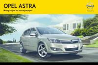
OPEL ASTRA
Инструкция по эксплуатации
Представленные на сайте изображения автомобилей могут отличаться от автомобилей, доступных в дилерских центрах. Отображение цветов на экранах различных устройств может незначительно отличаться от цвета реального автомобиля. В стандартное оборудование автомобилей могут входить не все опции и варианты отделки интерьера и экстерьера, видимые на изображениях. Некоторые опции могут быть доступны за дополнительную плату.
Любая информация, размещенная на данном сайте, носит исключительно справочный характер и ни при каких обстоятельствах не является публичной офертой, определяемой положениями Статьи 437 (2) Гражданского кодекса Российской Федерации. Все цены, указанные на сайте, не являются окончательными и устанавливаются дилерскими центрами на индивидуальной основе. Для получения подробной информации, обращайтесь в официальные дилерские центры.
Бренд Opel не гарантирует своевременность, точность и полноту информации на сайте, а также беспрепятственный доступ к сайту в любое время. Опубликованная на данном сайте информация может быть изменена в любое время без предварительного уведомления.
Opel Astra
Инструкция по эксплуатации
Введение
3
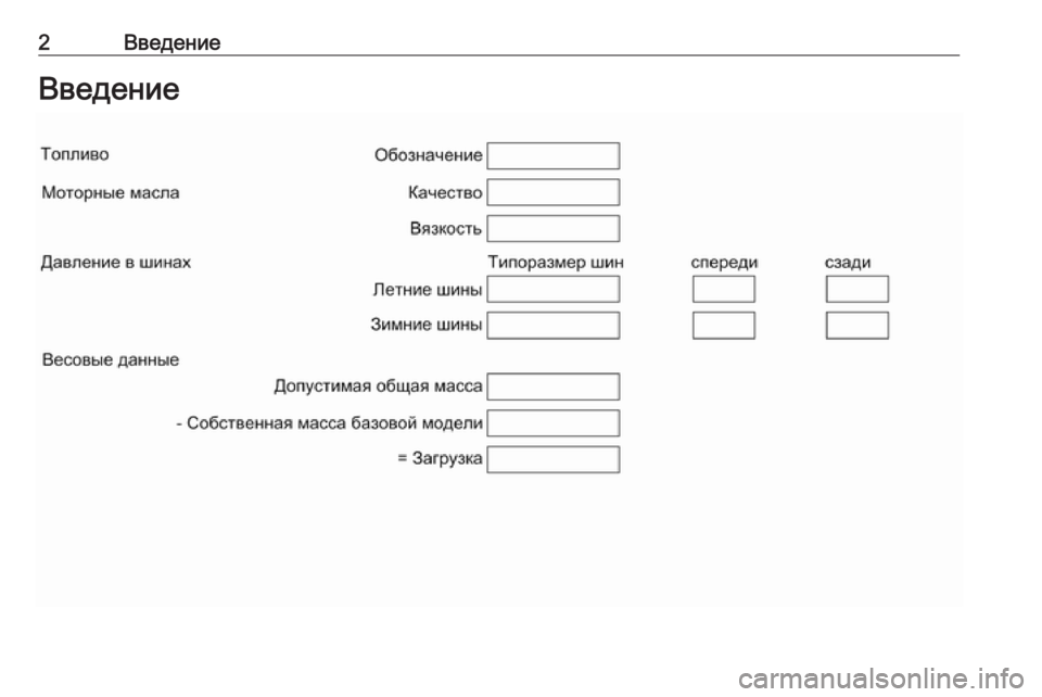
Технические данные
автомобиля
Запишите параметры Вашего авто‐
мобиля на предыдущей странице
и храните их в легко доступном
месте. Найти эту информацию
можно в разделах «Техническое об‐
служивание» и «Технические дан‐
ные», а также на типовой табличке
автомобиля.
Введение
Ваш автомобиль — это оптимальное
сочетание передовой технологии,
безопасности, экологичности и эко‐
номичности.
Настоящее Руководство пользова‐
теля содержит всю необходимую
для уверенного и эффективного
управления Вашим автомобилем
информацию.
Не только Вы, но и пассажиры
также должны знать о несчастных
случаях и травмах, которые могут
возникнуть при неправильной эксп‐
луатации автомобиля. Расскажите
им об этом.
Обязательно выполняйте дей‐
ствующие законы и предписания
той страны, в которой находитесь.
Соответствующее законодатель‐
ство может отличаться от приве‐
денной в настоящем Руководстве
информации.
При необходимости посещения
станции техобслуживания мы реко‐
мендуем обращаться в авторизо‐
ванный сервисный центр Opel.
Все авторизованные сервисные
центры Opel предложат Вам пер‐
воклассный сервис по умеренным
ценам. Опытные специалисты,
прошедшие обучение на фирме
Opel, обслужат Ваш автомобиль,
руководствуясь оригинальными
технологическими инструкциями
компании.
Пакет с литературой для клиента
должен всегда находиться в авто‐
мобиле.
Как пользоваться
настоящим
Руководством
■ В настоящем руководстве содер‐
жатся описания всех опций
и функций, доступных для этой
модели. Некоторые описания,
включая функции дисплея
и меню, могут не относиться
к вашему автомобилю по
причине выбранного варианта
модели, технических
характеристик страны поставки,
наличия специального
оборудования или
принадлежностей.
■ Предварительный обзор Вы най‐
дете в главе «Коротко».
■ В содержании в начале данного
руководства и в каждом разделе
указано местоположение инфор‐
мации.
■ Конкретную информацию можно
найти с помощью Алфавитного
указателя.
Назад
к
обзору
4
Введение
■ В настоящем Руководстве поль‐
зователя описаны автомобили
с левым расположением руле‐
вого колеса. Обслуживание авто‐
мобилей с правым рулевым ко‐
лесом выполняется аналогично.
■ В Руководстве пользователя ис‐
пользованы заводские обозначе‐
ния двигателя. Соответствую‐
щие торговые обозначения при‐
ведены в разделе «Технические
данные».
■ Указания направления, напри‐
мер, влево — вправо или вперед —
назад, всегда приводятся отно‐
сительно направления движе‐
ния.
■ Экранные дисплеи автомобиля
могут не поддерживать конкрет‐
ный язык пользователя.
■ Сообщения, отображаемые на
дисплее, а также надписи внутри
салона приводятся жирным
шрифтом.
Опасность,
Предупреждение
и Внимание
9 Опасность
Текст, отмеченный
9 Опасность, содержит инфор‐
мацию, связанную с риском
смертельного исхода. Прене‐
брежение этими сведениями
может оказаться опасным для
жизни.
9 Предупреждение
Текст, помеченный
9 Предупреждение, содержит
информацию, связанную с рис‐
ком несчастного случая или
травмы. Пренебрежение этими
сведениями может стать причи‐
ной травмы.
Внимание
Текст, помеченный Внимание,
информирует о том, что автомо‐
биль может быть поврежден.
Пренебрежение этой информа‐
цией может привести к повреж‐
дению автомобиля.
Символы
Ссылки на страницы обозначаются
с помощью 3. 3 означает «см. стр.».
Желаем Вам счастливого пути.
Adam Opel AG
Назад
к
обзору
6
Коротко
Коротко
Исходные сведения,
необходимые при
вождении
Отпирание автомобиля
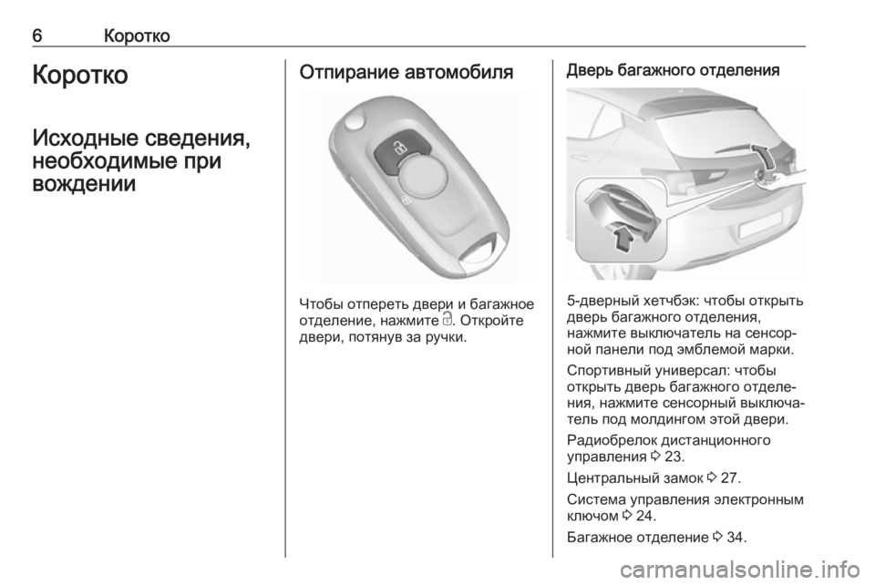
Чтобы отпереть двери и багажное
отделение, нажмите на кнопку c.
Откройте двери, потянув за ручки.
Чтобы открыть заднюю торцевую
откидную дверь, нажмите выклю‐
чатель на сенсорной панели под
рукояткой.
Пульт дистанционного управления
3
22, центральный замок 3 23,
багажное отделение 3 27.
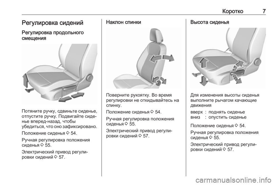
Регулировка сидений
Установка сиденья
в требуемое положение
Потяните ручку, сдвиньте сиденье,
отпустите ручку.
Положение сиденья 3 41, регули‐
ровка сиденья 3 41.
Назад
к
обзору
Коротко
7
9 Опасность
Чтобы избежать травмирования
во время срабатывания по‐
душки безопасности, не придви‐
гайтесь к рулевому колесу
ближе чем на 25 см.
Спинки сидений
Потяните рычаг, отрегулируйте на‐
клон и отпустите рычаг. Сиденье
должно зафиксироваться в новом
положении с характерным щел‐
чком.
Положение сиденья 3 41, регули‐
ровка сиденья 3 41.
Высота сиденья
Для изменения высоты сиденья
выполните рычагом качающие дви‐
жения
вверх = поднять сиденье
вниз = опустить сиденье
Положение сиденья 3 41, регули‐
ровка сиденья 3 41.
Назад
к
обзору
8
Коротко
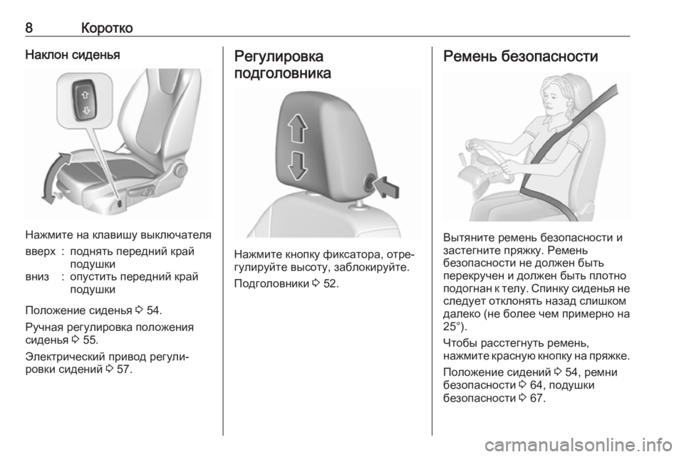
Наклон сиденья
Для изменения высоты сиденья
выполните рычагом качающие дви‐
жения
вверх = поднять передний край
подушки
вниз = опустить передний край
подушки
Положение сиденья 3 41, регули‐
ровка сиденья 3 41.
Регулировка
подголовника
Нажмите кнопку, отрегулируйте
высоту подголовника и отпустите
кнопку.
Подголовники 3 39.
Ремень безопасности
Вытяните ремень безопасности
и зафиксируйте его в замке. Ре‐
мень безопасности должен быть
неперекручен и плотно подогнан
к телу. Нельзя откидывать спинку
слишком далеко (не более 25°).
Для того чтобы снять ремень, на‐
жмите красную кнопку на его замке.
Положение сидений 3 41, ремни
безопасности 3 45, подушки без‐
опасности 3 49.
Назад
к
обзору
Коротко
9
Регулировка зеркал
Внутреннее зеркало
Для уменьшения бликов поверните
рычаг на нижней части корпуса
зеркала.
Внутреннее зеркало 3 32, авто‐
матическое неослепляющее внут‐
реннее зеркало 3 33.
Наружные зеркала
Выбрать соответствующее наруж‐
ное зеркало заднего вида и отрегу‐
лировать его.
Выпуклые наружные зеркала
3
31, электронная регулировка
3
31, складные наружные зер‐
кала 3 31, обогрев наружных зер‐
кал 3 32.
Регулировка положения
рулевого колеса
Разблокировать рычаг, отрегули‐
ровать рулевое колесо, затем за‐
блокировать рычаг и убедиться,
что он полностью зафиксирован.
Запрещается регулировать руле‐
вое колесо и разблокировать рычаг
его регулировки во время движе‐
ния автомобиля.
Подушки безопасности 3 49, по‐
ложения зажигания 3 163.
Назад
к
обзору
Manufacturer: OPEL, Model Year: 2018,
Model line: ASTRA K,
Model: OPEL ASTRA K 2018
Pages: 369, PDF Size: 9.44 MB
Trending: adblue, двигател, Шины, Фильтр, Круиз контроль, Давление, engine
Page 1 of 369
Page 2 of 369
Page 3 of 369
Page 4 of 369
Page 5 of 369
Page 6 of 369
Page 7 of 369
Page 8 of 369
Page 9 of 369
Page 10 of 369
- Load next 10 pages
Trending: engine, Круиз контроль, adblue, Фильтр, интервал, Шины, Давление
View, print and download for free: OPEL ASTRA K 2018 Инструкция по эксплуатации (in Russian), 369 Pages, PDF Size: 9.44 MB. Search in OPEL ASTRA K 2018 Инструкция по эксплуатации (in Russian) online. CarManualsOnline.info is the largest online database of car user manuals. OPEL ASTRA K 2018 Инструкция по эксплуатации (in Russian) PDF Download.
All product names, logos, and brands are property of their respective owners.
Privacy Policy | About Us & Contact
Много людей покупают машины из вторых рук, как правило книжки по эксплуатации при этом отсутствуют, у меня не однократно спрашивали инструкцию по эксплуатации. Выкладываю кому нужно скачивайте. Уточняю это инструкция по эксплуатации, а не по римонту! yadi.sk/d/P6cjSXG6Ur5ieQ
yadi.sk/d/QD66qmSxVmdt3w
Цена вопроса: 0 ₽
Пробег: 129 900 км
Комментарии
5
Войдите или зарегистрируйтесь, чтобы писать комментарии, задавать вопросы и участвовать в обсуждении.
Интересно, если у вас 2-3 то где-то не хватает 👍
Ага, а у кого-то машина стоит, а как ее эксплуатировать — не знают
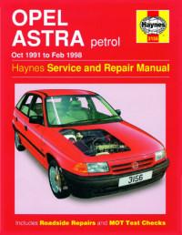
Руководство на английском языке по техническому обслуживанию и ремонту автомобиля Opel Astra 1991-1998 годов выпуска с бензиновыми двигателями.
- Автор: —
- Издательство: Haynes Publishing
- Год издания: —
- Страниц: 244
- Формат: PDF
- Размер: 142,4 Mb
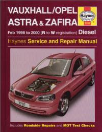
Руководство на английском языке по техническому обслуживанию и ремонту автомобилей Opel Astra/Zafira и Vauxhall Astra/Zafira 1998-2000 годов выпуска с дизельными двигателями.
- Автор: —
- Издательство: Haynes Publishing
- Год издания: 2001
- Страниц: 337
- Формат: PDF
- Размер: 65,8 Mb
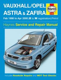
уководство на английском языке по техническому обслуживанию и ремонту автомобилей Opel Astra/Zafira и Vauxhall Astra/Zafira 1998-2000 годов выпуска с бензиновыми двигателями.
- Автор: —
- Издательство: Haynes Publishing
- Год издания: 2003
- Страниц: 301
- Формат: PDF
- Размер: 17,6 Mb
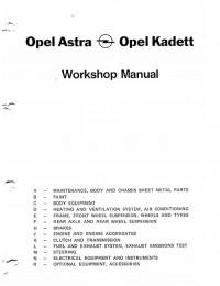
Руководство на английском языке по техническому обслуживанию и ремонту автомобилей Opel Astra и Opel Kadett 1991 года выпуска
- Автор: —
- Издательство: Delta Motor
- Год издания: 1993
- Страниц: 1070
- Формат: PDF
- Размер: 36,9 Mb
Сборник руководств по эксплуатации и техническому обслуживанию автомобиля Opel Astra H 2010-2014 годов выпуска.
- Автор: —
- Издательство: Opel AG
- Год издания: —
- Страниц: —
- Формат: PDF
- Размер: 42,6 Mb

Сборник руководств по эксплуатации и техническому обслуживанию автомобиля Opel Astra J 2013-2015 годов выпуска.
- Автор: —
- Издательство: Opel AG
- Год издания: —
- Страниц: —
- Формат: PDF
- Размер: 74,1 Mb
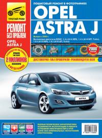
Руководство по эксплуатации, техническому обслуживанию и ремонту автомобиля Opel Astra с 2009 года выпуска с бензиновыми двигателями.
- Автор: С.Н. Погребной, А.А. Владимиров
- Издательство: Третий Рим
- Год издания: 2010
- Страниц: 360
- Формат: —
- Размер: —
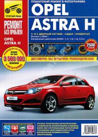
Руководство по эксплуатации, техническому обслуживанию и ремонту автомобиля Opel Astra с 2004 года выпуска с бензиновыми двигателями объемом 1,4/1,6/1,8/2,0 л.
- Автор: —
- Издательство: Третий Рим
- Год издания: —
- Страниц: 320
- Формат: —
- Размер: —
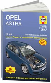
Руководство по эксплуатации, техническому обслуживанию и ремонту автомобиля Opel Astra 2004-2008 годов выпуска с бензиновыми двигателями.
- Автор: —
- Издательство: Алфамер
- Год издания: —
- Страниц: 312
- Формат: —
- Размер: —
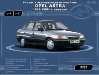
Мультимедийное руководство по эксплуатации и ремонту автомобиля Opel Astra 1991-1998 годов выпуска.
- Автор: —
- Издательство: —
- Год издания: —
- Страниц: —
- Формат: —
- Размер: 146,9 Mb
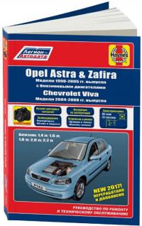
Руководство по техническому обслуживанию и ремонту + каталог расходных запчастей автомобилей Chevrolet Viva 2004-2008, Opel Astra и Opel Zafira 1998-2005 годов выпуска с бензиновыми двигателями.
- Автор: —
- Издательство: Легион-Автодата
- Год издания: —
- Страниц: 402
- Формат: —
- Размер: —
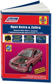
Руководство по техническому обслуживанию и ремонту + каталог расходных запчастей автомобилей Opel Astra и Opel Zafira 1998-2005 годов выпуска с дизельными двигателями объемом 1,7/2,0 л.
- Автор: —
- Издательство: Легион-Автодата
- Год издания: —
- Страниц: 368
- Формат: —
- Размер: —
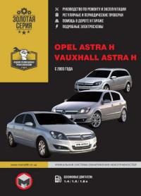
Руководство по эксплуатации и ремонту автомобилей Opel Astra и Vauxhall Astra с 2003 года выпуска с бензиновыми двигателями.
- Автор: —
- Издательство: Монолит
- Год издания: —
- Страниц: 352
- Формат: —
- Размер: —

Руководство по ремонту и эксплуатации автомобилей Chevrolet Viva, Opel Astra с 1998 и Opel Astra Classic с 2004 года выпуска с бензиновыми и дизельными двигателями.
- Автор: —
- Издательство: Монолит
- Год издания: —
- Страниц: 230
- Формат: —
- Размер: —
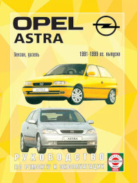
Руководство по эксплуатации и ремонту автомобилей Opel Astra 1991-1999 годов выпуска с бензиновыми и дизельными двигателями.
- Автор: —
- Издательство: Гуси-лебеди
- Год издания: —
- Страниц: 328
- Формат: —
- Размер: —
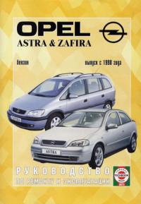
Руководство по эксплуатации и ремонту автомобилей Opel Astra и Opel Zafira с 1998 года выпуска с бензиновыми двигателями.
- Автор: —
- Издательство: Петит
- Год издания: 2005
- Страниц: 296
- Формат: PDF
- Размер: 6,6 Mb
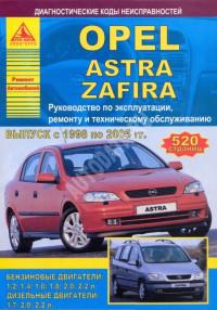
Руководство по эксплуатации, техническому обслуживанию и ремонту автомобилей Opel Astra и Opel Zafira 1998-2005 годов выпуска с бензиновыми и дизельными двигателями.
- Автор: —
- Издательство: Арго-Авто
- Год издания: —
- Страниц: 520
- Формат: —
- Размер: —
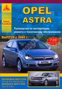
Руководство по эксплуатации, техническому обслуживанию и ремонту автомобиля Opel Astra с 2004 года выпуска с бензиновыми и дизельными двигателями.
- Автор: —
- Издательство: Арго-Авто
- Год издания: —
- Страниц: 728
- Формат: —
- Размер: —
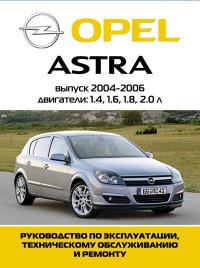
Мультимедийное руководство по техническому обслуживанию и ремонту автомобиля Opel Astra 2004-2006 годов выпуска.
- Автор: —
- Издательство: —
- Год издания: —
- Страниц: —
- Формат: —
- Размер: 268,7 Mb
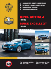
Руководство по эксплуатации и ремонту автомобилей Opel Astra с 2009 и Buick Excelle XT с 2010 года выпуска с бензиновыми и дизельными двигателями.
- Автор: —
- Издательство: Монолит
- Год издания: —
- Страниц: 370
- Формат: —
- Размер: —
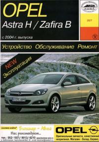
уководство по эксплуатации, техническому обслуживанию и ремонту автомобилей Opel Astra и Opel Zafira с 2004 года выпуска.
- Автор: Б.У. Звонаревский
- Издательство: Арус
- Год издания: 2006
- Страниц: 329
- Формат: PDF
- Размер: 19,5 Mb
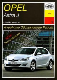
Руководство по эксплуатации, техническому обслуживанию и ремонту автомобиля Opel Astra с 2009 года выпуска.
- Автор: —
- Издательство: Арус
- Год издания: —
- Страниц: 348
- Формат: —
- Размер: —
Мультимедийное руководство по техническому обслуживанию и ремонту автомобилей Opel Astra и Opel Zafira с 1998 года выпуска.
- Автор: —
- Издательство: —
- Год издания: —
- Страниц: —
- Формат: —
- Размер: 252,4 Mb

Руководство по техническому обслуживанию и ремонту автомобиля Opel Astra с бензиновыми двигателями.
- Автор: —
- Издательство: —
- Год издания: —
- Страниц: 246
- Формат: PDF
- Размер: 53,3 Mb
Руководство по эксплуатации, техническому обслуживанию и ремонту автомобилей Opel Astra и Opel Zafira 1998-2006 годов выпуска.
- Автор: —
- Издательство: Мир Автокниг
- Год издания: —
- Страниц: 406
- Формат: PDF
- Размер: 401,1 Mb

Руководство по эксплуатации, техническому обслуживанию и ремонту автомобиля Opel Astra с 2009 года выпуска.
- Автор: —
- Издательство: Мир Автокниг
- Год издания: —
- Страниц: 352
- Формат: —
- Размер: —
- Manuals
- Brands
- Opel Manuals
- Automobile
- ASTRA 2014
- Owner’s manual
-
Contents
-
Table of Contents
-
Bookmarks
Related Manuals for Opel ASTRA 2014
Summary of Contents for Opel ASTRA 2014
-
Page 1
OPEL ASTRA Owner’s Manual… -
Page 3: Table Of Contents
Contents Introduction ……..2 In brief ……….6 Keys, doors and windows …. 23 Seats, restraints ……40 Storage ……..62 Instruments and controls … 102 Lighting ……..140 Climate control ……153 Driving and operating ….162 Vehicle care ……. 223 Service and maintenance ..
-
Page 4: Introduction
Introduction Introduction…
-
Page 5: Introduction
Operation is prices. Experienced mechanics Introduction similar for right-hand drive vehicles. trained by Opel work according to ■ The Owner’s Manual uses the Your vehicle is a designed specific Opel instructions. factory engine designations. The…
-
Page 6
3 means «see page». 9 Danger We wish you many hours of pleasurable driving. Text marked 9 Danger provides Adam Opel AG information on risk of fatal injury. Disregarding this information may endanger life. 9 Warning Text marked 9 Warning provides information on risk of accident or injury. -
Page 7
Introduction… -
Page 8: In Brief
In brief In brief Vehicle unlocking 5-door hatchback, Sports tourer Initial drive information To open the tailgate, push the Press button c to unlock the doors touchpad switch below the brand and load compartment. Open the emblem. doors by pulling the handles.
-
Page 9: Seat Adjustment
In brief Seat adjustment 3-door hatchback 4-door notchback Seat positioning To open the tailgate, push the brand Press button x on the remote emblem at the bottom half. control for at least 2 seconds; the boot lid opens slightly. Pull handle, slide seat, release Press button x on remote control to handle.
-
Page 10
In brief Seat backrests Seat height Seat inclination Pull lever, adjust inclination and Lever pumping motion Lever pumping motion release lever. Allow the seat to = seat higher = front end higher engage audibly. down = seat lower down = front end lower Seat position 3 42, Seat adjustment Seat position 3 42, Seat adjustment Seat position 3 42, Seat adjustment… -
Page 11: Head Restraint Adjustment
In brief Head restraint adjustment Power seat adjustment Power seat adjustment 3 46, Seat folding 3 45. Operate switch 1: Press release button, adjust height, engage. forwards/ = length adjustment backwards Head restraints 3 40. upwards/ = height adjustment downwards upwards/ = inclination downwards…
-
Page 12: Seat Belt
In brief Seat belt Mirror adjustment Exterior mirrors Interior mirror Select the relevant exterior mirror and Pull out the seat belt and engage in adjust it. belt buckle. The seat belt must not be To reduce dazzle, adjust the lever on twisted and must fit close against the Convex exterior mirrors 3 33, the underside of the mirror housing.
-
Page 13: Steering Wheel Adjustment
In brief Steering wheel adjustment Unlock the lever, adjust the steering wheel, then engage the lever and ensure it is fully locked. Do not adjust the steering wheel unless the vehicle is stationary and the steering wheel lock has been released.
-
Page 14
In brief Instrument panel overview… -
Page 15
In brief Power windows ….. 35 10 Sport mode ……179 Eco button for stop-start system ……… 165 Exterior mirrors ….. 33 Central locking system ..25 Cruise control ….. 181 Unlock button for boot lid ..28 Fuel selector ……. 111 16 Climate control system .. -
Page 16
In brief Rear fog light …… 148 Instrument illumination ..149… -
Page 17
In brief… -
Page 18: Exterior Lighting
In brief Exterior lighting Headlight flash, high beam and low beam Automatic light control AUTO = automatic light control: Turn light switch: exterior lighting is switched headlight flash = pull lever on and off automatically = lights off high beam = push lever = activation or deactivation 8 = sidelights…
-
Page 19
In brief Horn Turn and lane-change signals Hazard warning flashers Operated with the ¨ button. lever up = right turn signal Press j. lever down = left turn signal Hazard warning flashers 3 147. Turn and lane-change signals 3 147, Parking lights 3 148. -
Page 20: Washer And Wiper Systems
In brief Washer and wiper systems Windscreen and headlight Rear window wiper washer Windscreen wiper Press the rocker switch to activate the rear window wiper: Pull lever. = fast upper = continuous Windscreen and headlight washer = slow switch operation system 3 104, Washer fluid 3 228.
-
Page 21: Climate Control
In brief Climate control Rear window washer Demisting and defrosting the windows Heated rear window, heated exterior mirrors Push lever. Press button V. Washer fluid is sprayed on the rear window and the wiper wipes a few Set the temperature control to the The heating is operated by pressing times.
-
Page 22: Starting Off
In brief Transmission Starting off Automatic transmission Manual transmission Check before starting off ■ Tyre pressure and condition 3 259, 3 308. ■ Engine oil level and fluid levels 3 225. ■ All windows, mirrors, exterior lighting and number plates are free from dirt, snow and ice and are operational.
-
Page 23
In brief Parking Starting the engine Stop-start system ■ Always apply the parking brake. Activate the manual parking brake without pressing the release button. Apply as firmly as possible on a downhill slope or uphill slope. Depress foot brake at the same time to reduce operating force. -
Page 24
In brief If the vehicle is on a downhill slope, engage reverse gear or set the selector lever to P before switching off the ignition. Turn the front wheels towards the kerb. ■ Lock the vehicle with button e on the radio remote control. -
Page 25: Keys, Doors And Windows
Keys, doors and windows Keys, doors and Keys, locks Key with foldaway key section windows Keys Replacement keys The key number is specified in the Keys, locks ……..23 Car Pass or on a detachable tag. Doors ……….. 28 The key number must be quoted Vehicle security ……
-
Page 26: Radio Remote Control
Keys, doors and windows Radio remote control Handle with care, protect from Radio remote control battery moisture and high temperatures and replacement avoid unnecessary operation. Replace the battery as soon as the range reduces. Fault If the central locking system cannot be operated with the radio remote control, it may be due to the following: ■…
-
Page 27: Central Locking System
Keys, doors and windows Memorised settings Central locking system Key with foldaway key section Whenever the key is removed from Unlocks and locks doors, load the ignition switch, the following compartment and fuel filler flap. settings are automatically memorised A pull on an interior door handle by the key: unlocks the respective door.
-
Page 28
Keys, doors and windows Unlocking The setting can be saved for the key Central locking buttons being used. Memorised settings Locks or unlocks all doors, the load 3 25. compartment and fuel filler flap from inside the passenger compartment. Unlocking and opening the tailgate 3 28. -
Page 29: Automatic Locking
Keys, doors and windows Fault in radio remote control Fault in central locking system the ignition key is removed (manual transmission) or the selector lever is system Unlocking moved to P position (automatic transmission). Manually unlock the driver’s door by Unlocking turning the key in the lock.
-
Page 30: Doors
Keys, doors and windows Doors 3-door hatchback 9 Warning Load compartment Use the child locks whenever children are occupying the rear Tailgate seats. Opening Using a key or suitable screwdriver, 5-door hatchback turn the child lock in the rear door to the horizontal position.
-
Page 31
Keys, doors and windows 4-door notchback Pressing button x opens the With the doors centrally locked, the tailgate even if the doors are locked. boot lid cannot be opened with button To unlock the boot lid, press button x in the centre console. Sports tourer x on the remote control for at least After unlocking, push the touchpad… -
Page 32: Vehicle Security
Keys, doors and windows Vehicle security Closing gases, which cannot be seen or smelled, could enter the vehicle. Anti-theft locking system This can cause unconsciousness and even death. 9 Warning Caution Do not use the system if there are people in the vehicle! The doors Before opening the tailgate check cannot be unlocked from the overhead obstructions, such as a…
-
Page 33: Anti-Theft Alarm System
Keys, doors and windows Activating Activation Activation without monitoring of passenger compartment and ■ Self-activated 30 seconds after locking the vehicle (initialisation of vehicle inclination the system) ■ Directly by pressing e on the radio remote control once more after locking Note Changes to the vehicle interior such…
-
Page 34
Keys, doors and windows 1. Close tailgate, bonnet, windows Status during the first 30 seconds of The alarm can be silenced by and sunroof. anti-theft alarm system activation: pressing any button on the radio remote control or by switching on the 2. -
Page 35: Exterior Mirrors
Keys, doors and windows Exterior mirrors If the control indicator d flashes when In position 0 no mirror is selected. the ignition is on, there is a fault in the system; the engine cannot be started. Convex shape Folding mirrors Switch off the ignition and repeat the The convex exterior mirror contains start attempt.
-
Page 36: Interior Mirrors
Keys, doors and windows Interior mirrors Heated mirrors Electric folding Manual anti-dazzle Turn control to 0, then push the Operated by pressing the Ü button. control down. Both exterior mirrors Heating works with the engine will fold. To reduce dazzle, adjust the lever on running and is switched off Push the control down again — both the underside of the mirror housing.
-
Page 37: Power Windows
Keys, doors and windows Windows Automatic anti-dazzle Windscreen stickers Do not attach stickers such as toll Windscreen road stickers or similar on the windscreen in the area of the interior Heat-reflecting windscreen mirror. Otherwise the detection zone of the sensor and the view area of the The heat-reflecting windscreen has a camera in the mirror housing could be coating which reflects solar radiation.
-
Page 38: Windows
Keys, doors and windows Pushing or pulling firmly to the second Child safety system for rear Keep a close watch on the detent and then releasing: window windows windows when closing them. moves up or down automatically with Ensure that nothing becomes safety function enabled.
-
Page 39: Heated Rear Window
Keys, doors and windows Heated rear window Initialising the power windows If the windows cannot be closed automatically (e.g. after disconnecting the vehicle battery), a warning message or a warning code is displayed in the Driver Information Centre. Vehicle messages 3 128. Activate the window electronics as follows: 1.
-
Page 40: Roof
Keys, doors and windows Roof A ticket holder is located on the backside of the sun visor. Sunroof 9 Warning Take care when operating the sunroof. Risk of injury, particularly to children. Keep a close watch on the movable parts when operating them.
-
Page 41: Glass Panel
Keys, doors and windows Glass panel If the sunroof is raised, it can be opened in one step by pressing p. Panorama roof Sunblind The sunblind is manually operated. Close or open the sunblind by sliding. When the sunroof is open, the sunblind is always open.
-
Page 42: Seats, Restraints
Seats, restraints Seats, restraints Head restraints Adjustment Head restraints on front seats Position Head restraints ……40 9 Warning Front seats ……..42 Rear seats ……..49 Only drive with the head restraint Seat belts ……..49 set to the proper position. Airbag system ……
-
Page 43: Active Head Restraints
Seats, restraints Horizontal adjustment Head restraints on rear seats forwards. Thus the head is supported so that the risk of whiplash injury is reduced. Note Approved accessories may only be attached if the seat is not in use. To adjust horizontally, pull the head Height adjustment restraint forwards.
-
Page 44: Front Seats
Seats, restraints Front seats ■ Sit with shoulders as far back ■ Adjust the thigh support so that against the backrest as possible. there is a space approx. two fingers Set the backrest rake so that it is wide between the edge of the seat Seat position possible to easily reach the and the hollow of the knee.
-
Page 45
Seats, restraints Seat backrests Seat height 9 Warning Never store any subjects under the seats. Drive only with engaged seats and backrests. Seat positioning Pull lever, adjust inclination and Lever pumping motion release lever. Allow the backrest to = seat higher engage audibly. -
Page 46
Seats, restraints Seat inclination Lumbar support Adjustable thigh support Lever pumping motion Adjust lumbar support using the four- Pull the lever and slide the thigh way switch to suit personal support. = front end higher requirements. down = front end lower Moving support up and down: push switch up or down. -
Page 47: Seat Folding
Seats, restraints Seat folding Side bolster, OPC version To restore, slide the seat backwards. Move the backrest against the resistance to the upright position and Caution engage. The memory function allows the seat When seat height is in highest to engage in its original position. position, push head restraints down and lift up sun visors before Do not operate backrest inclination…
-
Page 48: Power Seat Adjustment
Seats, restraints In case the head restraint of the Keep a close watch on the seats 9 Danger folded backrest is blocked by the when adjusting them. Vehicle upper windscreen frame, slightly let passengers should be informed Move the backrest to an upright the seat move backwards before accordingly.
-
Page 49
Seats, restraints Seat height Move front of switch upwards/ Lumbar support downwards. Seat backrests Move switch upwards/downwards. Adjust lumbar support using the four- way switch to suit personal Seat inclination requirements. Turn switch forwards/backwards. Moving support up and down: push switch up or down. -
Page 50
Seats, restraints Armrest Heating Adjustable thigh support Pull the lever and slide the thigh The armrest can be slid forwards by Adjust heating to the desired setting support. 10 cm. Under the armrest there is a by pressing the ß button for the storage compartment. -
Page 51: Rear Seats
Seats, restraints Rear seats Seat belts Seat belts are designed to be used by only one person at a time. Child restraint system 3 56. Armrest Periodically check all parts of the belt system for damage, pollution and proper functionality. Have damaged components replaced.
-
Page 52: Three-Point Seat Belt
Seats, restraints Seat belt reminder Triggered belt pretensioners must be Withdraw the belt from the retractor, replaced by a workshop. Belt guide it untwisted across the body Front seats are equipped with a seat pretensioners can only be triggered and insert the latch plate into the belt reminder, indicated for driver seat once.
-
Page 53
Seats, restraints Removing 9 Warning The belt must not rest against hard or fragile objects in the pockets of your clothing. Seat belt reminder X 3 115. Height adjustment Adjust the height so that the belt lies across the shoulder. It must not lie To release belt, press red button on across the throat or upper arm. -
Page 54: Airbag System
Seats, restraints Airbag system Using the seat belt while Each airbag is triggered only once. Have deployed airbags replaced by pregnant a workshop. Furthermore, it may be The airbag system consists of a necessary to have the steering number of individual systems wheel, the instrument panel, parts of depending on the scope of the panelling, the door seals,…
-
Page 55: Side Airbag System
Seats, restraints Fit the seat belt correctly and engage securely. Only then is the airbag able to protect. Side airbag system Additionally there is a warning label The inflated airbags cushion the on the side of the instrument panel, impact, thereby reducing the risk of visible when the front passenger door injury to the upper body and head of is open, or on the front passenger sun…
-
Page 56: Curtain Airbag System
Seats, restraints Curtain airbag system 9 Warning The curtain airbag system consists of an airbag in the roof frame on each Keep the area in which the airbag side. This can be identified by the inflates clear of obstructions. word AIRBAG on the roof pillars. The hooks on the handles in the roof frame are only suitable for The curtain airbag system is triggered…
-
Page 57
Seats, restraints Use the ignition key to choose the Risk of fatal injury for an adult position: person on a seat with deactivated *OFF = front passenger airbag is front passenger airbag. deactivated and will not inflate in the event of a collision. -
Page 58: Child Restraints
Child restraint systems Status remains until the next change. used on the front passenger seat. Control indicator for airbag We recommend the Opel child Airbag deactivation 3 54. deactivation 3 115. restraint system which is tailored Airbag label 3 52.
-
Page 59
Seats, restraints Ensure that the mounting location of the child restraint system within the vehicle is correct, see following tables. Allow children to enter and exit the vehicle only on the side facing away from the traffic. When the child restraint system is not in use, secure the seat with a seat belt or remove it from the vehicle. -
Page 60: Child Restraint Installation Locations
Seats, restraints Child restraint installation locations Permissible options for fitting a child restraint system On front passenger seat Weight and age class activated airbag deactivated airbag On rear outboard seats On rear centre seat Group 0: up to 10 kg or approx.
-
Page 61
Seats, restraints Permissible options for fitting an ISOFIX child restraint system On rear outboard Weight class Size class Fixture On front passenger seat seats On rear centre seat Group 0: up to 10 kg ISO/R1 X or approx. 10 months Group 0+: up to 13 kg ISO/R1 X or approx. -
Page 62
Seats, restraints = Suitable for particular ISOFIX restraint systems of the ‘specific-vehicle’, ‘restricted’ or ‘semi-universal’ categories. The ISOFIX restraint system must be approved for the specific vehicle type. IUF = Suitable for ISOFIX forward-facing child restraint systems of universal category approved for use in this weight class. = No ISOFIX child restraint system approved in this weight class. -
Page 63: Top-Tether Fastening Eyes
Seats, restraints ISOFIX child restraint Top-tether fastening eyes systems Depending on country specific equipment, the vehicle might have two or three fastening eyes. Top-Tether fastening eyes are marked with the symbol : for a child seat. On Hatchback and Sports Tourer fastening eyes are on the backside of rear seats.
-
Page 64: Storage
Storage Storage Storage compartments The glovebox features a pen holder, a credit card holder, a coin holder and an adapter for the locking wheel nuts. 9 Warning The glovebox should be closed whilst Storage compartments ….62 driving. Do not store heavy or sharp Load compartment …….
-
Page 65: Front Storage
Storage Front storage Additional cupholders are located in Depending on the version, the rear armrest. Fold down the cupholders are located under a cover A storage compartment is located armrest. in the centre console. Slide cover next to the steering wheel. backwards.
-
Page 66: Underseat Storage
Storage Underseat storage Armrest storage Storage in the rear armrest Storage under the front armrest Fold down armrest and open cover. Press button in the recess and pull out drawer. Maximum load: 3 kg. To Close cover before folding the Press button to fold up the armrest.
-
Page 67: Centre Console Storage
Storage Centre console storage A further storage compartment is located under the intermediate shelf. Fold up the intermediate shelf and fix Front console it in the vertical position. The frame of the cupholder can be reintegrated to stow bottles. Rear console Press button to remove the frame of the cupholder.
-
Page 68: Rear Carrier System
Storage Rear carrier system The wheelbase of a bicycle must not exceed 1.15 metres. Otherwise the secure fastening of a bicycle is not Rear carrier system for two possible. bicycles If not in use, the carrier system must be slid back into the vehicle floor. There must not be any objects on the bicycles that could become loose during transportation.
-
Page 69
Storage Completely pull out the rear carrier Install the tail lamps Open out the lamp support on the system until you hear it engage. back of the tail lamp completely. Ensure that it is not possible to push in the rear carrier system without pulling the release lever again 9 Warning It is only permissible to fit objects… -
Page 70
Storage Lock the rear carrier system Check the cable and lamp position to The rear carrier system is locked make sure these are correctly when the clamping levers are Swivel the right clamping lever (1) installed and are securely located. swivelled by approx. -
Page 71
Storage Unfold pedal crank recesses Adapting the rear carrier system to a bicycle Remove the pedal crank mounts from the pedal crank recesses. Fold one or both pedal crank Press the release lever and withdraw recesses upwards until the diagonal the wheel recesses. -
Page 72
Storage Push the release lever on the strap The rear bicycle must have its front retainer and remove the strap wheel facing right. retainer. Attaching a bicycle to the rear carrier Prepare the bicycle for attachment system If the bicycle has curved pedal cranks, screw in the pedal crank unit all the way (position 1). -
Page 73
Storage Put on the bicycle. The pedal crank Place the wheel recesses such that here must be placed in the pedal the bicycle is more or less horizontal. crank recess opening, as shown in Here, the distance between the the illustration. pedals and the tailgate should be at least 5 cm. -
Page 74
Storage The settings for the wheel recesses and on the rotary lever on the pedal crank recess should be noted and saved for each bicycle. Correct presetting will facilitate refitting of the bicycle. Tighten the attachment screw for the Align the bicycle in the longitudinal pedal bearing mount to its maximum direction of the vehicle: Slightly point by hand. -
Page 75
Storage Removing a bicycle from the rear Retracting the rear carrier system Insert the strap retainer and pull carrier system tightly downwards as far as possible. Push the pedal crank mounts into the Undo strap retainers on both bicycle pedal crank recess, as shown in the Press release lever and slide in wheel tyres. -
Page 76
Storage Push the clamping lever down and pull both lamp supports out of the recesses. Disengage the locking lever on the Swivel first the left clamping lever (1), diagonal support and fold both pedal followed by the right clamping lever crank recesses down. -
Page 77
Storage Rear carrier system for four powered bicycles to the pull-out carrier. The maximum load per bicycles bicycle on the adapter is 20 kg. The wheelbase of a bicycle must not exceed 1.15 metres. Otherwise the secure fastening of a bicycle is not possible. -
Page 78
Storage Pull release lever up. The system will not engage correctly, do not fit Caution disengages and travels quickly out of objects to the system and slide the the bumper. system back. Seek the assistance Consult your bicycle dealer before of a workshop. -
Page 79
Storage Fold out tail lamps Swivel both clamping levers Assembling the bicycle rack sidewards as far as they will go. Otherwise safe functionality is not guaranteed. Fold out wheel recesses Fold out both tail lamps. Lift the rack at the rear (1) and pull it backwards. -
Page 80
Storage 1. Rotate the pedals into position (as shown in the illustration) and put the bicycle on the foremost wheel recess. Make sure that the bicycle stands centrally on the wheel recesses. 3. Secure both bicycle wheels to the Push down the rack (1) and swivel wheel recesses using the strap handle (2) backwards to engage. -
Page 81
Storage Attaching the adapter When carrying more than two bicycles, the adapter must be fixed before the second bicycle is attached. 4. Guide the strap attached to the 2. Turn the lever (1) forwards and adapter underneath the lever for hold, then lower the adapter (2) at folding back the rear carrier the rear. -
Page 82
Storage Use the longer accessory mounting bracket to attach the third bicycle to the rack. 3. Position the bicycles on the rear 6. Additionally secure both bicycle carrier system alternately aligned wheels of the fourth bicycle to the to the left and to the right. wheel recesses using the Use the short accessory mounting tensioning straps. -
Page 83
Storage It is recommended to attach a ■ With attached adapter: 9 Warning warning sign at the rearmost bicycle to increase visibility. 9 Warning When folding the rear carrier system forwards again, take care Fold the rear carrier system Take care when disengaging the that the system is engaged backwards rear carrier system as it will tilt… -
Page 84
Storage 3. Turn the lever (1) forwards and hold. 4. Lift the adapter (2) at the rear and remove. Disassembling the bicycle rack 2. Unbutton the strap. Fold the rack backwards, then push forwards until it stops (1). Press the rack down at the rear (2). Fold in wheel recesses Fold in both wheel recesses. -
Page 85
Storage Swivel both clamping levers inwards as far as they will go. Fold in tail lamps Swivel in both tail lamps. Fold in number plate holder Lift the number plate holder and fold it forwards. Retracting the rear carrier system Caution Stow the strap retainers accurately. -
Page 86: Load Compartment
Storage Load compartment ■ Guide the seat belts through side Ensure that the seat belts of the supports to protect them against outboard seats are placed in the damage. When folding the corresponding belt guides. The rear seat backrest is divided into backrests, pull the seat belts along two parts.
-
Page 87
Storage ■ Press and hold the catch to push or damage to the load or vehicle in the head restraints down 3 40. the event of hard braking or a ■ Fold up the rear armrest. collision. ■ Pull switch on left or right sidewall of the load compartment to fold the corresponding part of the rear seat. -
Page 88
Storage If the vehicle is to be loaded via a The backrests are properly engaged The seat belt of the centre seat could rear door, take the seat belt out of when the red marks on both sides be blocked when the backrest is the seat backrest guide and put it near the release lever are no longer folded up too quickly. -
Page 89
Storage Raise the seat cushion and fold the Remove the seat cushion ■ To attach, apply seat cushion as backrest shown in the illustration and engage both levers. Open the pass-through in the rear centre backrest ■ Fold down the rear armrest. ■… -
Page 90: Load Compartment Cover
Storage 3-door and 5-door hatchback Removing The closed cover can be secured Press both buttons and fold down from the side of the load cover. compartment. Turn the knob 90°: Maximum load: 0.5 kg. knob = cover secured from the Unhook retaining straps from tailgate.
-
Page 91
Storage Lift cover at the rear and push it Opening cover Cover in upper position upwards at the front. Remove the cover. If the height adjustable cover is mounted in the middle or upper position, the load compartment cover can be stowed below it. Height adjustable cover 3 90. -
Page 92: Rear Floor Storage Cover
Storage Rear floor storage cover Removing cover Rear floor cover, 3-door hatchback, 5-door hatchback The removed cover can be stored under the rear floor cover like shown Open the load compartment cover. in the graphic. Pull the release lever on the right side Rear floor storage cover 3 90.
-
Page 93
Storage Height adjustable cover, 3-door Lifting Lowering hatchback, 5-door hatchback To lift the cover to a higher level, pull To lower the cover, pull the strap the loop backwards and lift the rear backwards and push down the front The height adjustable cover can be edge of the cover onto the centre of the cover at the same time. -
Page 94
Storage Note Rear floor cover, Sports tourer ■ If mounted in position 2 or 3, the space between the rear floor cover and the height adjustable cover can be used as a stowage compartment. ■ The height adjustable cover can be lifted and hooked in with the strap when it is mounted in position 1 or 2. -
Page 95: Lashing Eyes
Storage Lashing eyes ■ hooks, plate upwards to lock the adapter. To remove, turn the handle plate down ■ service box, and move out of the rail. ■ strap set. Variable partition net The components are fitted in rails on both side panels using adapters and hooks.
-
Page 96
Storage Net pocket Installation of hooks in the rails Service box Insert adapters into the required Insert the hook in the desired position Install two hooks in the upper rail. position in the rails. The net pocket first in the upper groove of the rail and Insert the upper brackets of the box can be suspended from the adapters. -
Page 97: Safety Net
Storage Strap set Passengers must not be transported behind the safety net. Installation Behind the rear seats Alternatively install both hooks in the lower rail. Plug in the lower brackets Insert the adapters of the strap set in of the box from above into the lower a rail.
-
Page 98: Warning Triangle
Storage Warning triangle Behind the front seats Installation of the rod 3-door hatchback, 5-door hatchback Attach strap to eyes underneath the There are two installation openings in rear seat cushion. the roof frame: suspend and engage rod of net at one side, compress rod Fold backrests forward.
-
Page 99: First Aid Kit
Storage First aid kit Sports tourer 4-door notchback 5-door hatchback Fold down straps. Stow the warning Stow the warning triangle in the triangle in the space behind the straps recess on the left side of the load on the inside of the tailgate. compartment.
-
Page 100
Storage 3-door hatchback Sports tourer 4-door notchback Fold down strap. Stow the first aid kit Stow the first aid kit in the stowage Stow the first aid kit in the space in the space behind a strap on the compartment behind the warning behind the mesh net on the right side inside of the tailgate. -
Page 101: Roof Rack System
Storage Roof rack system 5-door hatchback, 4-door notchback Sports tourer with roof railing Roof rack For safety reasons and to avoid damage to the roof, the vehicle approved roof rack system is recommended. For further information contact your workshop. Follow the installation instructions and remove the roof rack when not in use.
-
Page 102: Loading Information
Storage Loading information ■ Use the four hooks at the sidewalls ■ Do not allow the load to protrude of the load compartment for above the upper edge of the hanging up carrier bags. Maximum backrests. load: 5 kg per hook. ■…
-
Page 103
Storage vehicle weight (see identification and 4-door notchback, for the plate 3 286) and the EC kerb Sports tourer it is 100 kg. The roof load is the combined weight of the weight. roof rack and the load. To calculate the payload, enter the data for your vehicle in the Weights table at the front of this manual. -
Page 104: Instruments And Controls
Instruments and controls Instruments and Controls Steering wheel controls controls Steering wheel adjustment Controls ……..102 Warning lights, gauges and indi‐ cators ……… 110 Information displays ….121 Vehicle messages …… 128 Trip computer ……132 Vehicle personalisation ….134 The Infotainment system, the cruise control and a connected mobile phone can be operated via the…
-
Page 105: Horn
Instruments and controls Heated steering wheel Horn The recommended grip areas of the steering wheel are heated quicker Activate heating by pressing * and to a higher temperature than the Press j. other areas. button. Activation is indicated by the LED in the button.
-
Page 106: Windscreen Wiper/Washer
Instruments and controls Windscreen wiper/washer Adjustable wiper interval Automatic wiping with rain sensor Windscreen wiper Wiper lever in position P. P = automatic wiping with rain sensor Turn the adjuster wheel to adjust the = fast desired wipe interval: The rain sensor detects the amount of = slow short = turn adjuster wheel…
-
Page 107
Instruments and controls Adjustable sensitivity of the rain Windscreen and headlight sensor washer Keep the sensor free from dust, dirt and ice. Turn the adjuster wheel to adjust the Pull lever. Washer fluid is sprayed sensitivity: onto the windscreen and the wiper = turn adjuster wheel wipes a few times. -
Page 108: Outside Temperature
Instruments and controls Rear window wiper/washer The rear window washer system is deactivated when the fluid level is low. Outside temperature Push lever. Washer fluid is sprayed onto the rear window and the wiper Press the rocker switch to activate the wipes a few times.
-
Page 109
Instruments and controls Time and date settings ■ Set date format: Changes indication of date between MM/DD/ CD 300/CD 400/CD400plus YYYY and DD.MM.YYYY. Press the CONFIG button. The menu ■ Display clock: Switches on/off Settings is displayed. indication of time on the display. Select Time Date. -
Page 110: Power Outlet
Instruments and controls Power outlets Adjust all settings. Set date To adjust the time settings, select the Set Date menu item. Turn the multifunction knob to adjust the first setting. Press the multifunction knob to confirm the input. The coloured background moves to the next setting.
-
Page 111: Cigarette Lighter
Instruments and controls Cigarette lighter A further 12 Volt power outlet is located in the rear console. Fold the cover downwards. Sports tourer: A 12 Volt power outlet is located at the left sidewall in the load compartment. Do not exceed the maximum power consumption of 120 watts.
-
Page 112: Warning Lights, Gauges And Indi- Cators
Instruments and controls Warning lights, gauges Odometer Some versions are equipped with a reset knob between speedometer and indicators and Driver Information Centre: to reset hold the knob depressed for a Instrument cluster few seconds with the ignition on. In some versions, the needles of the Trip odometer counts up to a distance instruments briefly rotate to the end of 2000 km and then restarts at 0.
-
Page 113: Fuel Selector
Instruments and controls During liquid gas operation, the 1 off = petrol operation Caution system automatically switches over to 1 illumi‐ = liquid gas operation petrol operation when gas tanks are nates If the needle is in the red warning empty 3 111.
-
Page 114: Service Display
Instruments and controls Displays the coolant temperature. left area = engine operating temperature not yet reached central = normal operating area temperature right area = temperature too high Caution If engine coolant temperature is too high, stop vehicle, switch off engine.
-
Page 115: Control Indicators
Instruments and controls code appears in the Driver Information Centre. Have engine oil and filter changed by a workshop within one week or 500 km (whichever occurs first). Driver Information Centre 3 121. Service information 3 283. Control indicators The control indicators described are not present in all vehicles.
-
Page 116
Instruments and controls Control indicators in the instrument cluster… -
Page 117: Seat Belt Reminder
Instruments and controls Control indicators in the centre Bulb replacement 3 231, Fuses When the ignition is switched on, the control indicator illuminates for 3 251. console approx. 4 seconds. If it does not Turn signals 3 147. illuminate, does not go out after 4 seconds or illuminates whilst Seat belt reminder driving, there is a fault in the airbag…
-
Page 118: Malfunction Indicator Light
Instruments and controls * illuminates yellow. Illuminates when the engine is Flashes when the engine is running running The front passenger airbag is deactivated 3 54. Stop, switch off engine. Vehicle Fault that could lead to catalytic battery is not charging. Engine converter damage.
-
Page 119: Electric Parking Brake
Instruments and controls Electric parking brake Flashes 9 Warning Electric parking brake is in service m illuminates or flashes red. mode. Stop vehicle, apply and Stop. Do not continue your release the electric parking brake to Illuminates journey. Consult a workshop. reset.
-
Page 120: Electronic Stability Control Off
Instruments and controls Upshift Illuminates with power steering Interference due to external sources of ultrasound. Once the source of disabled [ illuminates green as control interference is removed, the system Failure in the power steering system. indicator, or is shown as a symbol in will operate normally.
-
Page 121: Engine Oil Pressure
Instruments and controls Have the cause of the fault remedied Continue driving until % Flashes by a workshop. extinguishes. If possible, do not allow Fault in system or tyre without engine speed to drop below pressure sensor mounted (e.g. spare Flashes 2000 rpm.
-
Page 122: High Beam Assist
Instruments and controls 3. Move out of the flow of traffic as Flashes Illuminates when high beam is on or quickly as possible without during headlight flash 3 141, or when Fuel used up. Refuel immediately. impeding other vehicles. high beam is on with high beam assist Never run the tank dry.
-
Page 123: Driver Information Centre
Instruments and controls Information displays Fog light Adaptive cruise control > illuminates green. m illuminates white or green. Driver Information Centre The front fog lights are on 3 147. Illuminates white The Driver Information Centre (DIC) The system is on. is located in the instrument cluster Rear fog light between speedometer and…
-
Page 124
Instruments and controls ■ trip/fuel information Selecting menus and functions The menus and functions can be ■ vehicle messages, displayed as selected via the buttons on the turn code numbers 3 128. signal lever. In the Uplevel-Combi-Display, menu pages can be selected by pushing the MENU button, Menu symbols are indicated in the top line of the display: In the Uplevel-Display the following… -
Page 125
Instruments and controls Vehicle Information Menu Press the MENU button to select the Vehicle Information Menu, or on Uplevel-Combi-Display select X. Turn the adjuster wheel to select a submenu. Press the SET/CLR button to confirm. Follow the instructions given in the submenus. -
Page 126
Instruments and controls ■ Speed Warning: if exceeding the Trip/Fuel Information Menu Reset trip odometer by pressing the preset speed, a warning chime will SET/CLR button on the turn signal Press the MENU button to select the be activated lever for a few seconds or by pressing Trip/Fuel Information Menu, or select the reset knob between speedometer W on Uplevel-Combi-Display. -
Page 127
Instruments and controls Submenus are: ■ Top Consumers: List of top comfort ■ Economy Trend: Displays the consumers currently switched on is average consumption development ■ Shift indication: Current gear is displayed in descending order. Fuel over a distance of 50 km. Filled indicated inside an arrow. -
Page 128: Info-Display
Instruments and controls Performance Menu ■ Coolant Temp.: Display of coolant Depending on the Infotainment temperature. system, the Graphic-Info-Display is available in two versions. ■ Battery Volt.: Display of vehicle battery voltage. Graphic-Info-Display, Colour-Info-Display Depending on the vehicle configuration the vehicle has a Graphic- or Colour-Info-Display.
-
Page 129
Instruments and controls Colour-Info-Display ■ vehicle messages 3 128 Selecting with the Infotainment system ■ settings for vehicle personalisation 3 134 The type of information and how it is displayed depends on the equipment of the vehicle and the settings made. Selecting menus and settings Menus and settings are accessed via the display. -
Page 130: Vehicle Messages
Instruments and controls Vehicle messages Press (the outer ring) Vehicle messages on the Midlevel-Display ■ To select or activate the marked option Messages are indicated mainly in the Driver Information Centre (DIC), in ■ To confirm a set value some cases together with a warning ■…
-
Page 131
Instruments and controls No. Vehicle message No. Vehicle message No. Vehicle message Depress brake pedal to release 24 Number plate light failure 54 Water in diesel fuel filter electric parking brake 25 Left front turn signal failure 55 Diesel particle filter is full Turn steering wheel, switch 3 168 26 Left rear turn signal failure… -
Page 132
Instruments and controls The vehicle messages are displayed No. Vehicle message No. Vehicle message as text. Follow the instructions given 68 Service power steering 128 Bonnet open in the messages. The system displays messages 69 Service suspension system 134 Park assist fault, clean bumper regarding the following topics: 70 Service level control system 136 Service parking assist… -
Page 133: Warning Chimes
Instruments and controls Vehicle messages on the ■ If a warning message or a warning 1. Switch off immediately any code appears in the Driver electric consumers which are not Colour-Info-Display Information Centre. required for a safe ride, e.g. seat Some important messages appear heating, heated rear window or ■…
-
Page 134: Trip Computer
Instruments and controls Trip computer ■ Trip odometer 1 ■ Trip odometer 2 The menus and functions can be ■ Range selected via the buttons on the turn ■ Average consumption signal lever 3 121. ■ Instantaneous consumption ■ Average speed ■…
-
Page 135
Instruments and controls ■ Trip odometer 2 button, making it possible to display different trip information for different ■ Average consumption 2 drivers. ■ Average speed 2 ■ Trip odometer 1 ■ Average consumption 1 ■ Average speed 1 Trip odometer ■… -
Page 136: Vehicle Personalisation
Instruments and controls Vehicle personalisation Range Instantaneous consumption Range is calculated from current fuel Display of the instantaneous tank content and current consumption. The vehicle’s behaviour can be consumption. The display shows personalised by changing the settings Average speed average values. in the Info-Display.
-
Page 137
Instruments and controls The following settings can be ■ Sport steering: Steering support is selected by turning and pressing the reduced. multifunction knob: ■ Swap backlight colour main instr.: ■ Sport mode settings Changes the instrument illumination colour. ■ Languages ■… -
Page 138
Instruments and controls Vehicle settings Auto collision preparation: Activates or deactivates the automatic brake functionality of the vehicle in the event of imminent collision danger. The following is selectable: the system will take over brake control, warn by chimes only or is deactivated. Side blind zone alert: Changes the settings for the side blind spot alert system. -
Page 139
Instruments and controls Stop door lock if door open: Press the CONFIG button on the ■ Display Settings Activates or deactivates the Infotainment system faceplate to ■ Vehicle Settings automatic door locking function enter the Configuration menu. In the corresponding submenus the while a door is open. -
Page 140
Instruments and controls Phone Settings active after switching the ignition off Automatic Collision Preparation: and on again. Activates or deactivates the See Infotainment system manual for automatic brake functionality of the further information. Air Conditioning Mode: Activates or vehicle in the event of imminent deactivates cooling when switching Navigation Settings collision danger. -
Page 141
Instruments and controls the automatic door locking function after driving-off. Delay Door Lock: Activates or deactivates the delayed door locking function. ■ Remote Lock/Unlock/Start Remote Lock Feedback: Activates or deactivates the hazard warning flasher feedback whilst locking. Remote Unlock Feedback: Activates or deactivates the hazard warning flasher feedback whilst unlocking. -
Page 142: Lighting
Lighting Lighting Exterior lighting Light switch with Automatic light control Light switch Exterior lighting ……140 Interior lighting ……149 Lighting features ……150 Turn light switch: AUTO = automatic light control: low Turn light switch: beam is switched on and = lights off off automatically 8 = sidelights…
-
Page 143: High Beam
Lighting High beam In the Driver Information Centre with When the automatic light control Uplevel-Display or Uplevel-Combi- function is switched on and the Display, the current status of the engine is running, the system automatic light control is displayed. switches between daytime running light and headlights automatically When switching on the ignition, depending on the lighting conditions…
-
Page 144: Headlight Range Adjustment
Lighting Headlight range It switches to low beam when: The green control indicator l illuminates continuously when the ■ a sensor detects the lights of adjustment assist is activated, the blue one 7 oncoming or preceding vehicles illuminates when high beam is on. Manual headlight range ■…
-
Page 145: Daytime Running Lights
Lighting Dynamic automatic headlight Vehicles with Xenon headlight For deactivation operate the same levelling 3 143. procedure as described above. f will system not flash when function is deactivated. Headlights when driving abroad Daytime running lights The asymmetrical headlight beam Daytime running lights increase extends visibility at the edge of the visibility of the vehicle during daylight.
-
Page 146
Lighting With the light switch in position Country lighting Dynamic curve lighting AUTO all lighting functions are Activated automatically at a speed available. range between approx. 55 and 115 km/h. The beam of light and the The following functions are available brightness is different between the also with light switch in position 9: left and the right side. -
Page 147
Lighting Control indicator f 3 120. Activation If a headlight flash is activated when the high beam is on, the high beam Reversing function assist will be deactivated. If the headlights are on and reverse If a headlight flash is activated when gear is engaged, both corner lights the high beam is off, the high beam are switched on. -
Page 148
Lighting If there are no restrictions detected, A special topographical evaluation Automatic high beam activation the system switches back to high function detects preceding vehicles operates at a speed above 40 km/h beam. on hills or slopes by recognising the and deactivates below 20 km/h. -
Page 149: Hazard Warning Flashers
Lighting Fault in adaptive forward lighting In the event of an accident with airbag For three flashes, e.g. when changing deployment the hazard warning lanes, press the lever until resistance system flashers are activated automatically. is felt and then release. When the system detects a failure in When a trailer is connected, turn the Adaptive forward lighting system,…
-
Page 150: Parking Lights
Lighting Parking lights Reversing lights Light switch in position AUTO: switching on front fog lights will switch The reversing light comes on when headlights on automatically. the ignition is on and reverse gear is selected. Rear fog lights Misted light covers The inside of the light housing may mist up briefly in poor, wet and cold weather conditions, in heavy rain or…
-
Page 151: Interior Lighting
Lighting Interior lighting On vehicles with light sensor, the Operate rocker switch: brightness can only be adjusted when = automatic switching on the exterior lights are on and the light Instrument panel and off. sensor detects night conditions. press u = on. illumination control press v = off.
-
Page 152: Lighting Features
Lighting Lighting features Reading lights Rear courtesy lights Centre console lighting Spotlight incorporated in the interior lighting comes on when headlights are switched on. Entry lighting Welcome lighting The following lights are switched on for a short time by unlocking the vehicle with the radio remote control: Illuminates in conjunction with the Operated with s and t buttons in…
-
Page 153: Exit Lighting
Lighting Activation or deactivation of this They will switch off automatically after If the driver’s door is not closed the function can be changed in the menu a delay and will be activated again if lights switch off after two minutes. Settings in the Info-Display.
-
Page 154
Lighting ■ Auxiliary heater ■ Heated rear window and mirrors ■ Heated seats ■ Fan In the second stage a message which confirms the activation of the vehicle battery discharge protection will be displayed in the Driver Information Centre. Switching off electric lights To prevent discharge of the vehicle battery when the ignition is switched off, some interior lights are switched… -
Page 155: Climate Control
Climate control Climate control Climate control systems Heating will not be fully effective until the engine has reached normal operating temperature. Heating and ventilation system Air distribution Climate control systems ….. 153 s = to windscreen and front door Air vents ……..160 windows Maintenance ……
-
Page 156: Air Conditioning System
Climate control Air conditioning system Demisting and defrosting Cooling n ■ Press button V: fan automatically Press button n to switch on cooling. In addition to the heating and switches to higher speed, the air Activation is indicated by the LED in ventilation system, the air distribution is directed towards the the button.
-
Page 157
Climate control If no cooling or drying is required, Maximum cooling 9 Warning switch off the cooling system for fuel saving reasons. Activated cooling The exchange of fresh air is might inhibit Autostops. reduced in air recirculation mode. In operation without cooling the air Air recirculation system 4 humidity increases, so the windows may mist up from inside. -
Page 158: Electronic Climate Control
Climate control Demisting and defrosting the Note If the V button is pressed while the windows V engine is running, an Autostop will be inhibited until the V button is pressed again. If the V button is pressed while the engine is in an Autostop, the engine will restart automatically.
-
Page 159
Climate control Automatic mode AUTO ■ Press n to switch on optimal cooling and demisting. Activation is indicated by the LED in the button. ■ Set the preselected temperatures for driver and front passenger using the left and right rotary knob. Recommended temperature is 22 °C. -
Page 160
Climate control If the minimum temperature Lo is set, ■ Press button V. Activation is Manual settings the climate control system runs at indicated by the LED in the button. Climate control system settings can maximum cooling, if cooling n is be changed by activating the buttons ■… -
Page 161
Climate control Pressing the upper button longer: the Return to automatic air distribution: If no cooling or drying is required, fan runs at maximum speed. press button AUTO. switch off the cooling system for fuel saving reasons. When the cooling To return to automatic mode: Press Cooling n system is switched off, no engine… -
Page 162: Air Recirculation Mode
Climate control Air vents Air recirculation mode 4 compartment air deteriorates, which may cause the vehicle Adjustable air vents occupants to feel drowsy. At least one air vent must be open In warm and very humid ambient air while the cooling is on. conditions, the windscreen might mist up from outside, when cold air is directed to it.
-
Page 163: Pollen Filter
Climate control Maintenance Air conditioning regular operation Air intake In order to ensure continuously efficient performance, cooling must be operated for a few minutes once a month, irrespective of the weather and time of year. Operation with cooling is not possible when the outside temperature is too low.
-
Page 164: Driving And Operating
Driving and operating Driving and operating Driving hints Pedals To ensure the pedal travel is Control of the vehicle uninhibited, there must be no mats in the area of the pedals. Driving hints ……. 162 Never coast with engine not running (except during Steering Starting and operating ….
-
Page 165: Starting And Operating
Driving and operating Starting and operating Ignition switch positions ■ Power windows ■ Sunroof New vehicle running-in ■ Power outlets Do not brake unnecessarily hard for Power to the Infotainment system will the first few journeys. continue to operate for 30 minutes or until the key is removed from the During the first drive, smoke may ignition switch, regardless of whether…
-
Page 166: Overrun Cut-Off
Driving and operating Do not operate the accelerator pedal. Starting the vehicle at low Possible reasons for a non-starting engine: temperatures Diesel engine: turn the key to position 2 for preheating until control ■ Clutch pedal not operated (manual The start of the engine without indicator ! extinguishes.
-
Page 167
Driving and operating Stop-start system Deactivation The stop-start system helps to save fuel and to reduce the exhaust emissions. When conditions allow, it switches off the engine as soon as the vehicle is at a low speed or at a standstill, e.g. -
Page 168
Driving and operating Conditions for an Autostop Otherwise an Autostop will be Restart of the engine by the inhibited. The stop-start system checks if each driver of the following conditions is fulfilled: Certain settings of the climate control Depress the clutch pedal to restart the system may inhibit an Autostop. -
Page 169
Driving and operating ■ the engine temperature is too low firmly as possible on downhill or Note uphill slopes. Depress the foot In the event of an accident with ■ the charging level of the vehicle brake at the same time to reduce airbag deployment, the engine is battery is below a defined level operating force. -
Page 170: Engine Exhaust
Driving and operating Engine exhaust take up to 25 minutes. Typically it full continue driving or warning needs between 7 and 12 minutes. code 55 appears in the Driver Autostop is not available and fuel Information Centre. consumption may be higher during 9 Danger % illuminates when diesel particle this period.
-
Page 171: Automatic Transmission
Driving and operating Automatic transmission Cleaning takes place quickest at high rectified by a workshop as soon as engine speeds and loads. possible. In an emergency, driving can be continued for a short period, The control indicator % extinguishes The automatic transmission permits keeping vehicle speed and engine as soon as the self-cleaning automatic gearshifting (automatic…
-
Page 172: Selector Lever
Driving and operating Selector lever Do not accelerate while engaging a gear. Never depress the accelerator pedal and brake pedal at the same time. When a gear is engaged, the vehicle slowly begins to creep when the brake is released. Engine braking To utilise the engine braking effect, select a lower gear in good time when…
-
Page 173: Manual Mode
Driving and operating Manual mode In manual mode no automatic shifting ■ Special programmes automatically to a higher gear takes place at high adapt the shifting points when engine revolutions. driving up inclines or down hills. ■ When starting off in snowy or icy Electronic driving conditions or on other slippery surfaces, the electronic…
-
Page 174
Driving and operating Only the highest gear is available. 3. Insert a screwdriver into the Depending on the fault, 2nd gear may opening as far as it will go and also be available in manual mode. move the selector lever out of P or Shift only when vehicle is at a N. -
Page 175: Manual Transmission
Driving and operating Manual transmission Brakes Caution The brake system comprises two It is not advisable to drive with the independent brake circuits. hand resting on the selector lever. If a brake circuit fails, the vehicle can still be braked using the other brake circuit.
-
Page 176: Parking Brake
Driving and operating Parking brake ABS starts to regulate brake pressure Fault as soon as a wheel shows a tendency to lock. The vehicle remains Manual parking brake 9 Warning steerable, even during hard braking. If there is a fault in the ABS, the ABS control is made apparent wheels may be liable to lock due through a pulse in the brake pedal…
-
Page 177: Electric Parking Brake
Driving and operating Electric parking brake Do not operate electric parking brake Dynamic braking when vehicle is system too often without engine moving running because this will discharge When the vehicle is moving and the the vehicle battery. switch m is kept pulled, the electric parking brake system will decelerate Before leaving the vehicle, check the the vehicle, but will not apply…
-
Page 178: Traction Control System
Driving and operating Ride control systems Control indicator m flashes: electric The hill start assist is not active during an Autostop. parking brake is not fully applied or released. When continuously Traction Control system flashing, release electric parking The Traction Control system (TC) is a brake and retry applying.
-
Page 179: Electronic Stability Control
Driving and operating press button b briefly to deactivate ESC is operational after each engine 9 Warning start as soon as the control indicator TC, k illuminates. Deactivation is b extinguishes. displayed as status message in the Do not let this special safety Driver Information Centre.
-
Page 180
Driving and operating For a more sporty behaviour ESC and Deactivation, OPC version ■ press button b twice briefly within TC can be deactivated separately: 2 seconds: TC is inactive, ESC is operable without engine power ■ press button b briefly: only Traction reduction, k and n illuminate control system is inactive, ESC remains active, k illuminates… -
Page 181: Sport Mode
Driving and operating Interactive driving system TOUR mode The settings of the systems are Flex Ride adapted to a comfort driving style: Flex Ride driving system allows the ■ Damping of shock absorbers reacts driver to select between three driving more softly.
-
Page 182
Driving and operating automatically changes the settings Personalised settings in the OPC Flex Ride driving system allows within the selected driving mode or, the driver to select between three Sport mode when recognising greater variations, driving modes: The driver can select the functions of the driving mode is changed for the ■… -
Page 183: Driver Assistance Systems
Driving and operating Driver assistance NORMAL mode For safety reasons the cruise control cannot be activated until the foot In NORMAL mode, when neither systems brake has been operated once. SPORT nor OPC button is pressed, Activating in first gear is not possible. all settings of the systems are adapted to standard values.
-
Page 184
Driving and operating Activation Automatic deactivation: Accelerate to the desired speed and ■ vehicle speed below approx. turn thumb wheel to SET/-, the 30 km/h, current speed is stored and ■ vehicle speed above approx. maintained. Control indicator m in 200 km/h, instrument cluster illuminates green. -
Page 185: Speed Limiter
Driving and operating Speed limiter Press button L. If cruise control or maximum speed. Speed limit is displayed in the Driver Information adaptive cruise control has been The speed limiter prevents the Centre. activated before, it is switched off vehicle exceeding a preset maximum when speed limiter is activated and speed.
-
Page 186: Adaptive Cruise Control
Driving and operating The limited speed will flash in the By pressing button m to activate Driver Information Centre and, cruise control or adaptive cruise depending on the vehicle, additionally control or by switching off the ignition, a chime sounds during this period. speed limiter is also deactivated and the stored speed is deleted.
-
Page 187
Driving and operating Activation by setting the speed The accelerator pedal can be 9 Warning released. Adaptive cruise control Adaptive cruise control can be remains activated while gearshifting. activated between 50 km/h and The complete driver attention is 180 km/h. always required while driving with Overriding set speed Accelerate to the desired speed and… -
Page 188
Driving and operating Increase speed current speed can be stored and maintained by turning the thumb With adaptive cruise control active, wheel to SET/-. hold thumb wheel turned to RES/+: speed increases continuously in large Resume stored speed increments, or activate repeatedly If the system is switched on but RES/+: speed increases in small inactive, then turn thumb wheel to… -
Page 189
Driving and operating The green illuminated vehicle ahead 9 Warning control indicator A is displayed in the speedometer when the system The driver accepts full detects a vehicle in the driving path. responsibility for the appropriate If this symbol does not display, or following distance based on traffic, displays briefly, adaptive cruise weather and visibility conditions. -
Page 190
Driving and operating ■ Electronic Stability Control is Driver’s attention operating, ■ Use adaptive cruise control carefully on bends or mountain ■ there is no traffic and nothing roads, as it can lose the vehicle detected on the road sides for ahead and need time to detect it several minutes. -
Page 191
Driving and operating So if a new vehicle is detected, the longer detects any vehicle ahead, brake the vehicle in time to avoid a system may accelerate instead of then control indicator A will collision with a much slower vehicle or braking. -
Page 192
Driving and operating Hill and trailer considerations Radar unit consult a workshop to verify and correct the adaptive cruise control sensor position. Settings Settings can be changed in the Auto collision preparation menu in the vehicle personalisation, 3 134. System performance on hills and when towing a trailer depends on your Fault vehicle speed, vehicle load, traffic… -
Page 193: Forward Collision Alert
Driving and operating Vehicle messages 3 128. on vehicles equipped with adaptive cruise control 3 184. Forward collision alert ■ Forward collision alert based on front camera system The forward collision alert can help to on vehicles with traditional cruise avoid or reduce the harm caused by control or none 3 181.
-
Page 194
Driving and operating Alerting the driver Note that the alert timing sensitivity Press button E; the current setting is setting is shared with the following shown on the Driver Information A green illuminated vehicle ahead distance setting of the adaptive cruise Centre. -
Page 195
Driving and operating Settings Alerting the driver A green illuminated vehicle ahead Settings can be changed in the Auto control indicator A lights up in the collision preparation menu in the instrument cluster when the system vehicle personalisation 3 134. has detected a vehicle in the driving Forward collision alert based on path. -
Page 196: Following Distance
Driving and operating Following distance Deactivation approaching a vehicle ahead too The system can be deactivated. indication rapidly, it may not provide you Press button V repeatedly until the enough time to avoid a collision. The following distance indication following message appears in the The driver accepts full displays the distance to a preceding Driver Information Centre.
-
Page 197: Active Emergency Braking
Driving and operating emergency braking applies, the driver shall continue to apply the brake is warned by the forward collision pedal as the driving situation alert 3 191. dictates. The feature uses various inputs (e.g. radar sensor, brake pressure, vehicle Brake preparation system speed) to calculate the probability of When approaching a vehicle ahead…
-
Page 198
Driving and operating results immediately in a strong System limitations braking. This function helps the driver The active emergency braking has brake quicker and stronger before the limited or no function during rain, imminent collision. snow or heavy dirt, as the radar sensor can be covered by a water 9 Warning film, dust, ice or snow. -
Page 199: Parking Assist
Driving and operating Parking assist The system uses two different For activating or deactivating parking frequencies for the front and rear assist push button r or D once sensors, respectively, each with a briefly. For activating or deactivating different sound. advanced parking assist push button r or D for approx.
-
Page 200
Driving and operating The front parking assist can also be On version with Uplevel-Combi- activated at a low speed by pressing Display, the distance to a front and the parking assist button r or D rear obstacle is indicated by changing distance lines around the vehicle. -
Page 201
Driving and operating Fault The sensor may detect a non- Caution existing object (echo disturbance) In the event of a fault in the system, caused by external acoustical or r illuminates or a message is Performance of the sensor can be mechanic disturbances. -
Page 202: Advanced Parking Assist
Driving and operating Advanced parking assist Button D When looking for a parking slot, the system has to be activated by Advanced parking assist and parking pushing the button D for approx. assist 3 197 both use the same button one second.
-
Page 203
Driving and operating Functionality The parking slot suggestion of the The instructions show: system is accepted when the vehicle ■ a hint when driving faster than When the vehicle passes a row of is stopped by the driver within 30 km/h, cars and the system is activated, the 10 metres after the Stop message is ■… -
Page 204
Driving and operating vehicle messages 3 128 will be If an object is detected during parking instructions, Stop is indicated in the displayed. After approving the Driver Information Centre. Removing message by pressing the SET/CLR the object will resume the parking button, parking assist messages manoeuvre. -
Page 205: Side Blind Spot Alert
Driving and operating It is possible that the sensor detects Caution 9 Warning a non-existing object (echo disturbance) caused by external Performance of the sensor can be Side blind spot alert does not acoustical or mechanic reduced when sensors are replace driver vision.
-
Page 206: Rear View Camera
Driving and operating The system can be activated or Side blind spot alert does not operate deactivated in the menu Settings in when the left or right corners of the the Info-Display, vehicle rear bumper are covered with mud, personalisation 3 134. dirt, snow, ice or slush.
-
Page 207
Driving and operating The camera is mounted in the tailgate Warning symbols e.g. below the bumper or handle and has a viewing angle of Warning symbols are indicated as underneath the vehicle, are not 130°. triangles 9 on the picture which show displayed. -
Page 208: Traffic Sign Assistant
Driving and operating Traffic sign assistant Deactivation Road signs Beginning and end of: The camera is deactivated when a Functionality certain forward speed is exceeded or ■ motorways if reverse gear is not engaged for The traffic sign assistant system ■…
-
Page 209
Driving and operating An exclamation mark in a frame Traffic signs are displayed on the indicates that there is an add on sign page Traffic sign detection on the detected which cannot be recognised Driver Information Centre, chosen via by the system. the adjuster wheel on the turn signal lever 3 121. -
Page 210
Driving and operating The content of the traffic sign page is Once setting page is displayed, select also cleared during driving by pushing Off to deactivate pop-up function. the SET/CLR button on the turn signal Reactivated by selecting On. When lever for a longer time. -
Page 211: Lane Departure Warning
Driving and operating ■ traffic signs are incorrectly mounted Activation The driver assistance systems do or damaged not relieve the driver from full ■ traffic signs do not comply with the responsibility for vehicle Vienna Convention on traffic signs operation. (Wiener Übereinkommen über Straßenverkehrszeichen) Lane departure warning…
-
Page 212: Fuel
Driving and operating Fuel When the system recognises an Fault unintended lane change, the control The lane departure warning system indicator ) changes to yellow and Fuel for petrol engines may not operate properly when: flashes. Simultaneously a chime ■ the windscreen is not clean Only use unleaded fuel that complies sound is activated.
-
Page 213: Fuel For Diesel Engines
Driving and operating The boiling point depends on the Caution Caution pressure and mixing ratio. At ambient pressure, it is between -42 °C (pure Use of fuel that does not comply to Use of fuel that does not comply to propane) and -0.5 °C (pure butane).
-
Page 214
Driving and operating Pressing the LPG button switches Fill the tank completely at regular Caution between petrol and liquid gas intervals to prevent corrosion in the operation as soon as the required tank. Repairs and adjustments may only parameters (coolant temperature, be made by trained specialists in Faults and remedies gas temperature and minimum… -
Page 215
Driving and operating Refuelling 9 Danger Fuel is flammable and explosive. No smoking. No naked flames or sparks. If you can smell fuel in your vehicle, have the cause of this remedied immediately by a workshop. Caution Turn the thumb wheel clockwise. In case of misfuelling, do not If no further gas odour is perceptible switch on ignition. -
Page 216
Driving and operating Liquid gas refuelling Follow the operating and safety instructions of the filling station when refuelling. The filling valve for the liquid gas is behind the fuel filler cap. The fuel filler flap can only be opened The fuel filler cap can be retained in if the vehicle is unlocked. -
Page 217
A small quantity of liquid gas required which are available from can escape. Opel Distributors and from Opel Remove adapter and stow in vehicle. Authorised Repairers. Fit protective cap to prevent the penetration of foreign bodies into the… -
Page 218: Fuel Consumption — Co
ACME adapter: Belgium, Germany, EURO adapter: Spain Ireland, Luxembourg, Switzerland Emissions The fuel consumption (combined) of the model Opel Astra is within a range of 8.1 to 3.7 l/100 km. The CO emission (combined) is within a range of 189 to 99 g/km.
-
Page 219: Trailer Hitch
Driving and operating Trailer hitch Driving characteristics and General information The official fuel consumption and towing tips General information specific CO emission figures quoted Before attaching a trailer, lubricate relate to the EU base model with Only use towing equipment that has the coupling ball.
-
Page 220: Trailer Towing
Driving and operating Trailer towing The permissible gross train weight Rear axle load must not be exceeded. This weight is When the trailer is coupled and the specified on the identification plate Trailer loads towing vehicle fully loaded, the 3 286. permissible rear axle load (see The permissible trailer loads are identification plate or vehicle…
-
Page 221
Driving and operating Stowage of coupling ball bar Fitting the coupling ball bar Disengage and fold down the socket. Remove the sealing plug from the All versions except 3-door hatchback: The bag with the coupling ball bar is opening for the coupling ball bar and Press fastenings inward and fold the stowed in the rear stowage stow it. -
Page 222
Driving and operating Checking the tensioning of the Insert the tensioned coupling ball bar coupling ball bar in the opening and push firmly upwards until it audibly engages. The rotary handle snaps back into its original position resting against the coupling ball bar without a gap. -
Page 223
Driving and operating Eye for break-away stopping cable ■ The coupling ball bar must be firmly Open the protective flap and turn the engaged in the opening. key to position c to unlock the coupling ball bar. ■ The coupling ball bar must be locked and the key removed. -
Page 224: Trailer Stability Assist
Driving and operating Trailer stability assist If the system detects snaking movements, engine power is reduced and the vehicle/trailer combination is selectively braked until the snaking ceases. While system is working keep steering wheel as still as possible. Trailer stability assist (TSA) is a function of the Electronic Stability Control 3 177.
-
Page 225: Vehicle Care
Vehicle care Vehicle care General Information Vehicle storage Storage for a long period of time Accessories and vehicle If the vehicle is to be stored for several modifications General Information ….223 months: We recommend the use of genuine Vehicle checks ……224 ■…
-
Page 226: Vehicle Checks
Vehicle care Vehicle checks ■ Open the bonnet, close all doors website, where legally required. Only and lock the vehicle. entrust this work to an authorised recycling centre. Performing work ■ Disconnect the clamp from the negative terminal of the vehicle Gas vehicles must be recycled by a battery.
-
Page 227: Engine Oil
Vehicle care If the bonnet is opened during an 9 Danger Autostop, the engine will be restarted automatically for safety reasons. The ignition system and Xenon headlights use extremely high Closing voltage. Do not touch. Before closing the bonnet, press the support into the holder.
-
Page 228: Engine Coolant
Vehicle care Pull out the dipstick, wipe it clean, We recommend the use of the same insert it to the stop on the handle, pull grade of engine oil that was used at out and read the engine oil level. last change.
-
Page 229: Power Steering Fluid
Vehicle care Coolant level 9 Warning Caution Allow the engine to cool before opening the cap. Carefully open Too low a coolant level can cause the cap, relieving the pressure engine damage. slowly. To top up use a 1:1 mixture of released coolant concentrate mixed with clean tap water.
-
Page 230: Washer Fluid
Vehicle care Washer fluid Brakes In the event of minimum thickness of the brake lining, a squealing noise sounds during braking. Continued driving is possible but have the brake lining replaced as soon as possible. Once new brake linings are installed, do not brake unnecessarily hard for the first few journeys.
-
Page 231
Using an AGM vehicle battery Laying up the vehicle for more than In vehicles with stop-start system, be different from the original Opel 4 weeks can lead to battery sure to have the AGM (Absorptive vehicle battery may result in a lower discharge. -
Page 232: Wiper Blade Replacement
Vehicle care Diesel fuel system Charging the vehicle battery Meaning of symbols: ■ No sparks, naked flames or bleeding 9 Warning smoking. If the tank has been run dry, the diesel ■ Always shield eyes. Explosive fuel system must be bled. Switch on On vehicles with stop-start gases can cause blindness or the ignition three times for…
-
Page 233: Bulb Replacement
Vehicle care Bulb replacement Lift the wiper arm until it stays in the Lower wiper arm carefully. raised position, press button to disengage the wiper blade and Switch off the ignition and switch off remove. the relevant switch or close the doors. Attach the wiper blade slightly angled Only hold a new bulb at the base.
-
Page 234: Halogen Headlights
Vehicle care Halogen headlights Low beam (1) 2. Rotate the bulb holder anticlockwise to disengage. Withdraw the bulb holder from the 5-door hatchback, 4-door reflector. notchback, Sports tourer 1. Rotate the cap (1) anticlockwise and remove it. 3. Detach the bulb from the bulb Halogen headlights with separate holder and replace the bulb.
-
Page 235
Vehicle care High beam (2) Sidelights/Daytime running light (3) 2. Press latches together and withdraw the bulb holder from the reflector. 1. Rotate the cap (2) anticlockwise 1. Rotate the cap (3) anticlockwise and remove it. and remove it. Use the screwdriver to rotate the cap. -
Page 236
Vehicle care 3-door hatchback Low/High beam (1) 2. Rotate the bulb holder anticlockwise to disengage. Withdraw the bulb holder from the reflector. 1. Rotate the cap (1) anticlockwise Bi-Halogen Headlight (1) with one and remove it. bulb for low and high beam. Sidelight/Daytime running light (2). -
Page 237
Vehicle care Adaptive forward lighting Sidelight/Daytime running light (2) 9 Danger Adaptive forward lighting system uses Xenon headlights. Xenon headlights work under extremely high electrical voltage. Do not touch. Have bulbs replaced by a workshop. Sidelight/Daytime running lights are 2. Remove the bulb from the socket designed as Light Emitting Diodes by pulling. -
Page 238: Fog Lights
Vehicle care Fog lights Corner lighting 2. Rotate the bulb holder anticlockwise to disengage. Withdraw the bulb holder from the 5-door hatchback, 4-door reflector. notchback, Sports tourer 1. Rotate the cap anticlockwise and remove it. 3. Disengage the bulb from the plug 1.
-
Page 239
Vehicle care 3. Unscrew three screws and 8. Attach turn light assembly into the remove fog light assembly from bumper and fix with two screws. the bumper. 9. Engage both caps. 3-door hatchback 2. Unscrew both screws and remove turn light assembly from the bumper. -
Page 240: Front Turn Signal Lights
Vehicle care Front turn signal lights 3. Turn the bulb socket anti- clockwise and remove it from the reflector. 5-door hatchback, 4-door notchback, Sports tourer 4. Disengage the bulb socket from the plug connector by pressing the retaining lug. 5. Remove and replace the bulb socket with bulb and attach the plug connector.
-
Page 241
Vehicle care 3. Disengage the bulb socket from 5-door hatchback, 4-door notchback, the reflector by pressing both Sports tourer with Sport/GSi front retaining lugs. bumper The bulbs are accessible from beneath the vehicle. 2. Unscrew both screws and remove light assembly from the bumper. 4. -
Page 242
Vehicle care 3-door hatchback 2. Rotate bulb socket anticlockwise to disengage and withdraw from the reflector. 3. Disengage the bulb socket from the plug connector by pressing 1. Rotate cap (1) anticlockwise and the retaining lug. remove it. 4. Remove and replace the bulb 3. -
Page 243: Tail Lights
Vehicle care Tail lights 3. Carefully withdraw the tail light assembly from recesses and remove. Make sure that the cable 5-door hatchback duct remains in position. 4. Detach the cable from the retainer. 5. Detach the wiring plug from the bulb carrier.
-
Page 244
Vehicle care Close the cover and engage. Light assembly in the tailgate 4. Press the retaining lug and 7. Remove and replace the bulb by remove the bulb carrier from the withdrawing or pushing the bulb light assembly. slightly into the socket and 1. -
Page 245
Vehicle care 5. Remove and replace the bulb by 1. Remove cover on the responding 3. Carefully withdraw tail light withdrawing or pushing the bulb side. assembly from recesses and slightly into the socket and remove. Make sure that the cable rotating anticlockwise: duct remains in position. -
Page 246
Vehicle care Turn signal light (2) Sports tourer 6. Insert bulb holder and turn clockwise. Connect the wiring plug. Fit light assembly with the retaining pins into the recesses of the car body and tighten the securing nuts from the inside of the load compartment. -
Page 247
Vehicle care 2. Remove cover on the respective 4. Carefully withdraw tail light 7. Connect the wiring plug and press side. assembly from recesses and the cable into the retainer. Fit light remove. Make sure that the cable assembly with the retaining pins duct remains in position. -
Page 248
Vehicle care Light assembly in the tailgate 4. Remove the bulb holder by Rear fog light respectively reverse 1. Open the tailgate and remove the turning anticlockwise and replace light (2), depending on the side, can blind covers on the respective the bulb by withdrawing or be replaced by a cover in the tailgate side. -
Page 249
Vehicle care 3. Carefully withdraw the light assembly from the recesses and remove. 4. Detach wiring plug from bulb carrier. 2. Unscrew both plastic securing 3-door hatchback nuts from the inside by hand. 5. Remove the bulb holder by turning and replace the bulb by withdrawing or pushing the bulb slightly into the socket and rotating anticlockwise:… -
Page 250: Side Turn Signal Lights
Vehicle care Only turn signal light (2) can be 2. Unscrew three screws. Only rear fog light respectively changed. reverse light (2), depending on the 3. Remove the tail light assembly side, can be changed. 6. Insert and turn bulb holder from tailgate.
-
Page 251
Vehicle care 1. Slide lamp to its left side and 3. Pull bulb from bulb holder and remove with its right end. replace it. 4. Insert bulb holder and turn clockwise. 5. Insert left end of the lamp, slide to the left and insert right end. -
Page 252: Number Plate Light
Vehicle care 4. Insert bulb holder and turn 4. Pull bulb from bulb holder and clockwise. replace it. 5. Insert left end of the lamp, slide to 5. Insert bulb holder into lamp the left and insert right end. housing and turn clockwise. 6.
-
Page 253: Electrical System
Vehicle care Electrical system Fuses Data on the replacement fuse must match the data on the defective fuse. There are three fuse boxes in the vehicle: ■ in the front left of the engine compartment, ■ in left-hand drive vehicles, in the interior behind the storage compartment, or, in right-hand drive vehicles, behind the…
-
Page 254: Engine Compartment Fuse
Vehicle care Engine compartment fuse No. Circuit Engine control module Lambda sensor Fuel injection, ignition system Fuel injection, ignition system – Mirror heating, anti-theft alarm system Fan control, engine control module, transmission control module The fuse box is in the front left of the Lambda sensor, engine cooling engine compartment.
-
Page 255
Vehicle care No. Circuit No. Circuit No. Circuit 15 Engine control module 32 Airbag 47 Horn 16 Starter 33 Adaptive forward lighting, auto‐ 48 Radiator fan matic light control 17 Transmission control module 49 Fuel pump 34 Exhaust gas recirculation 18 Heated rear window 50 Headlamp levelling, adaptive 35 Exterior mirror, rain sensor… -
Page 256: Instrument Panel Fuse Box
Vehicle care Instrument panel fuse box No. Circuit Displays Exterior lights, body control module Exterior lights, body control module Infotainment system Infotainment system, instru‐ ment In right-hand drive vehicles, the fuse Power outlet, cigarette lighter box is located behind a cover in the Power outlet glovebox.
-
Page 257
Vehicle care Load compartment fuse No. Circuit 14 Diagnostic connector 3-door hatchback, 5-door 15 Airbag hatchback 16 Power outlet The fuse box is on the left side of the 17 Air conditioning system load compartment behind a cover. 18 Logistics 19 Body control module 20 Body control module Fold down the blind and remove. -
Page 258
Vehicle care Fuse assignments No. Circuit No. Circuit – 18 – Trailer outlet 19 Steering wheel heating Parking assist 20 Sunroof – 21 Heated front seats – 22 – – 23 – Power seat 24 – – 25 – – 26 –… -
Page 259: Vehicle Tools
Vehicle care Vehicle tools Sports Tourer and 4-door notchback Tools Vehicles with tyre repair kit Some tools and the towing eye are located together with the tyre repair kit in a tool box in the load compartment below the floor cover. 3-door and 5-door hatchback When assembling press the blind into the rubber grommets to reach full…
-
Page 260
Vehicle care Vehicles with spare wheel Variant 1b: 3-door and 5-door Variant 2: Sports Tourer hatchback with foldable wheel Variant 1a: 3-door and 5-door wrench hatchback with rigid wheel wrench The jack, the tools and the towing eye are in the tool box below the spare Same content as variant 1a, but with wheel in the load compartment. -
Page 261: Wheels And Tyres
Vehicle care Wheels and tyres Tyre designations Variant 3: 4-door notchback E.g. 215/60 R 16 95 H Tyre condition, wheel condition 215 = Tyre width, mm = Cross-section ratio (tyre Drive over edges slowly and at right height to tyre width), % angles if possible.
-
Page 262: Tyre Pressure Monitoring
Vehicle care Tyre pressures differ depending on If the tyre pressure must be reduced various options. For the correct tyre or increased on a vehicle with tyre pressure value, follow the procedure pressure monitoring system, switch below: off ignition. 1. Identify the body style. Tyre pressure monitoring 2.
-
Page 263
Vehicle care Note In countries where the tyre pressure monitoring system is legally required, the use of wheels without pressure sensors will invalidate the vehicle type approval. The current tyre pressures can be shown in the Vehicle Information Menu in the Driver Information Centre. -
Page 264
Vehicle care If the tyre pressure must be reduced Vehicle loading status Auto learn function or increased, switch off ignition. Adjust tyre pressure to load condition After changing wheels, the vehicle according to tyre information label or must be stationary for approx. Only mount wheels with pressure tyre pressure chart 3 308, and select 20 minutes, before the system… -
Page 265: Tread Depth
Vehicle care Tread depth indicators (TWI). Their position is 9 Warning indicated by markings on the Check tread depth at regular sidewall. intervals. Use of unsuitable tyres or wheels If there is more wear at the front than may lead to accidents and will Tyres should be replaced for safety the rear, swap round front wheels and invalidate the vehicle type…
-
Page 266: Tyre Repair Kit
Vehicle care Vehicles with steel wheels: When 5-door hatchback, 4-door notchback, General using locking wheel nuts, the wheel Sports tourer The use of tyre chains is not permitted covers might not be attached to the Always use fine mesh chains that add on the temporary spare wheel.
-
Page 267
Vehicle care The tyre repair kit is in a compartment 3. Remove the electrical connection under the floor cover in the load cable and air hose from the compartment or, on version with rear stowage compartments on the carrier system, in the drawer under underside of the compressor. -
Page 268
Vehicle care If the prescribed tyre pressure is 10. Set the rocker switch on the 6. Unscrew valve cap from defective not obtained within 10 minutes, compressor to I. The tyre is filled tyre. remove the tyre repair kit. Move with sealant. -
Page 269: Wheel Changing
Vehicle care 14. Detach the tyre repair kit. Push If unusual noise is heard or the catch on bracket to remove compressor becomes hot, turn sealant bottle from bracket. Screw compressor off for at least the tyre inflation hose to the free 30 minutes.
-
Page 270
Vehicle care Make the following preparations and ■ Do not start the vehicle when it is Alloy wheels: Disengage wheel observe the following information: raised on the jack. nut caps with a screwdriver and remove. To protect the wheel, ■ Park the vehicle on a level, firm and ■… -
Page 271
Vehicle care Fold out the wheel wrench and install ensuring that it locates securely and loosen each wheel nut by half a turn. The wheels might be protected by locking wheel nuts. To loosen these specific nuts first attach the key adapter onto the head of the nut before installing the wheel wrench. -
Page 272
Vehicle care Attach jack handle and with the jack correctly aligned rotate handle until wheel is clear of the ground. Sports Tourer, jack variant 2, 3 257: Attach wheel wrench and with the Set the jack to the necessary jack correctly aligned rotate wheel height. -
Page 273: Spare Wheel
Vehicle care 10. Align the valve hole in the wheel Jacking position for lifting cover with the tyre valve before platform installing. Install wheel nut caps. Install centre cap on alloy wheels. 11. Install vehicle jacking point cover on versions with sill panelling. 12.
-
Page 274
Vehicle care The spare wheel has always a steel To remove: Under the spare wheel there is the rim. box with vehicle tools. 1. Open the floor cover. 4. When, after a wheel change, no Caution wheel is placed in the spare wheel well, secure the tool box by The use of a spare wheel that is turning right back the wing nut and… -
Page 275
Vehicle care Stowing a damaged full size wheel in the spare wheel well, Sports Tourer and 4-door notchback Vehicles equipped with a full size spare wheel: 2. Place the loop end of the strap 4. Insert the strap through the through the front lashing eye on spokes of the wheel as shown in the appropriate side. -
Page 276
Vehicle care Vehicles equipped with a temporary 3. Take the extension bolt from the spare wheel: tool bag 3 257 and screw it in Secure a damaged full size wheel hand-tight using the hexagon key outside up with the wing nut in the of the wheel wrench. -
Page 277
Vehicle care Directional tyres Store jack and tools always in the Fit directional tyres such that they roll respective storage compartments in the direction of travel. The rolling and secure them by fixing. direction is indicated by a symbol Damaged wheel placed in the load (e.g. -
Page 278: Jump Starting
Vehicle care Jump starting ■ Never expose the vehicle battery to ■ Do not allow the terminals of one naked flames or sparks. lead to touch those of the other lead. ■ A discharged vehicle battery can Do not start with quick charger. already freeze at a temperature of ■…
-
Page 279: Towing
Vehicle care Towing Lead connection order: 2. After 5 minutes, start the other engine. Start attempts should be 1. Connect the red lead to the made for no longer than Towing the vehicle positive terminal of the booster 15 seconds at an interval of vehicle battery.
-
Page 280: Towing Another Vehicle
Vehicle care Towing another vehicle Caution Drive slowly. Do not drive jerkily. Excessive tractive force can damage the vehicle. When the engine is not running, considerably more force is needed to brake and steer. To prevent the entry of exhaust gases from the towing vehicle, switch on the air recirculation and close the Screw in the towing eye as far as it will…
-
Page 281: Appearance Care
Vehicle care Appearance care Caution Exterior care Drive slowly. Do not drive jerkily. Excessive tractive force can Locks damage the vehicle. The locks are lubricated at the factory using a high quality lock cylinder After towing, unscrew the towing eye. grease.
-
Page 282: Exterior Lights
Vehicle care If using a vehicle wash, comply with On vehicles with emblem touchpad: Polishing is necessary only if the paint the vehicle wash manufacturer’s when cleaning with a high-pressure has become dull or if solid deposits instructions. The windscreen wiper jet cleaner ensure a minimum have become attached to it.
-
Page 283
Vehicle care Sunroof Paintwork damage Liquid gas system Never clean with solvents or abrasive Rectify minor paintwork damage with 9 Danger agents, fuels, aggressive media a touch-up pen before rust forms. (e.g. paint cleaner, acetone- Have more extensive damage or rust Liquid gas is heavier than air and containing solutions etc.), acidic or areas repaired by a workshop. -
Page 284: Interior Care
Vehicle care Air shutter coloured upholstery. Removable stains and discolourations should be Clean the shutter system in the front cleaned as soon as possible. bumper to maintain correct functionality. Clean seat belts with lukewarm water or interior cleaner. Interior care Caution Interior and upholstery Close Velcro fasteners as open…
-
Page 285: Service And Maintenance
Service and maintenance Service and General information Iceland, Ireland, Italy, Latvia, Lithuania, Luxembourg, Macedonia, maintenance Malta, Montenegro, Netherlands, Service information Norway, Poland, Portugal, Romania, In order to ensure economical and Serbia, Slovakia, Slovenia, Spain, safe vehicle operation and to Sweden, Switzerland, United General information ….
-
Page 286: Recommended Fluids
Service and maintenance Recommended fluids, Make sure that the Service and aging control, whereas viscosity Warranty Booklet is completed grade gives information on the oil’s lubricants and parts correctly as continuous proof of thickness over a temperature range. service is essential if any warranty or Dexos is the newest engine oil quality Recommended fluids and goodwill claims are to be met, and is…
-
Page 287
Service and maintenance Select the appropriate engine oil Coolant and antifreeze based on its quality and on the Use only organic acid type-long life minimum ambient temperature coolant (LLC) antifreeze approved for 3 288. the vehicle. Consult a workshop. The system is factory filled with Additional engine oil additives coolant designed for excellent The use of additional engine oil… -
Page 288: Technical Data
Technical data Technical data Vehicle identification Identification plate Vehicle Identification Number Vehicle identification ….286 Vehicle data ……. 288 The identification plate is located on the front left door frame. The Vehicle Identification Number is visible through the windscreen.
-
Page 289: Engine Identification
Technical data Information on identification label: Specifications in the vehicle documents always have priority over 1 = Manufacturer those given in this manual. 2 = Type approval number 3 = Vehicle Identification Number Engine identification 4 = Permissible gross vehicle weight rating in kg The technical data tables show the 5 = Permissible gross train weight…
-
Page 290: Vehicle Data
Technical data Vehicle data Recommended fluids and lubricants European service schedule Required engine oil quality All European countries (except Belarus, Moldova, Russia, Turkey) Only Israel Engine oil quality Petrol engines Diesel engines Petrol engines Diesel engines (including CNG, LPG, E85) (including CNG, LPG, E85) dexos 1 –…
-
Page 291
Technical data International service schedule Required engine oil quality All countries outside Europe except Israel Only Belarus, Moldova, Russia, Turkey Engine oil quality Petrol engines Diesel engines Petrol engines Diesel engines (including CNG, LPG, E85) (including CNG, LPG, E85) dexos 1 ✔… -
Page 292
Technical data All countries outside Europe except Israel Only Belarus, Moldova, Russia, Turkey Engine oil quality Petrol engines Diesel engines Petrol engines Diesel engines (including CNG, LPG, E85) (including CNG, LPG, E85) ACEA A3/B3 ✔ – ✔ – ACEA A3/B4 ✔… -
Page 293
Technical data Engine data Sales designation A14XEL A14XER A14NEL A14NET A16XER A16LET A16XHT Engine identifier code Number of cylinders Piston displacement [cm 1398 1398 1364 1364 1598 1598 1598 Engine power [kW] at rpm 6000 6000 4200-6000 4900-6000 6000 5500 6000 Torque [Nm] at rpm… -
Page 294
Technical data Sales designation 2.0 OPC Engine identifier code A16SHT A18XER A20NFT A13DTE B16DTH A17DTN A17DTC Number of cylinders 1598 1796 1998 1248 1598 1686 1686 Piston displacement [cm Engine power [kW] at rpm 5500 6300 5300 4000 3500-4000 4000 4000 Torque [Nm] at rpm… -
Page 295
Technical data Sales designation 2.0 Turbo 2.0 Turbo Engine identifier code A17DTE A17DTF A17DTS A20DTH A20DTR Number of cylinders 1686 1686 1686 1956 1956 Piston displacement [cm Engine power [kW] at rpm 4000 4000 4000 4000 4000 Torque [Nm] at rpm 1750-2500 2000-2500 2000-2500… -
Page 296
Technical data Performance 3-door hatchback Engine A14XER A14NEL A14NET A16LET A16XHT A16SHT Maximum speed [km/h] Manual transmission Automatic transmission – – – – The maximum speed indicated is achievable at kerb weight (without driver) plus 200 kg payload. Optional equipment could reduce the specified maximum speed of the vehicle. -
Page 297
Technical data Engine A17DTS A20DTH A20DTR Maximum speed [km/h] Manual transmission Automatic transmission – – The maximum speed indicated is achievable at kerb weight (without driver) plus 200 kg payload. Optional equipment could reduce the specified maximum speed of the vehicle. 5-door hatchback Engine A14XEL… -
Page 298
Technical data Engine A16XHT A13DTE B16DTH A17DTE A17DTC A17DTF Maximum speed [km/h] Manual transmission Automatic transmission – – – – – The maximum speed indicated is achievable at kerb weight (without driver) plus 200 kg payload. Optional equipment could reduce the specified maximum speed of the vehicle. -
Page 299
Technical data 4-door notchback Engine A14XER A14NET A16LET A16XER A16XHT Maximum speed [km/h] Manual transmission Automatic transmission – The maximum speed indicated is achievable at kerb weight (without driver) plus 200 kg payload. Optional equipment could reduce the specified maximum speed of the vehicle. -
Page 300: Sports Tourer
Technical data Engine A17DTS A20DTH Maximum speed [km/h] Manual transmission Automatic transmission – The maximum speed indicated is achievable at kerb weight (without driver) plus 200 kg payload. Optional equipment could reduce the specified maximum speed of the vehicle. Sports tourer Engine A14XER A14NEL…
-
Page 301
Technical data Engine A13DTE B16DTH A17DTN A17DTE A17DTF Maximum speed [km/h] Manual transmission Automatic transmission – – – – – The maximum speed indicated is achievable at kerb weight (without driver) plus 200 kg payload. Optional equipment could reduce the specified maximum speed of the vehicle. -
Page 302: Vehicle Weight
Technical data Vehicle weight Kerb weight, basic model without any optional equipment 3-door hatchback Engine Manual transmission Automatic transmission with air conditioning A14XER 1393 – [kg] A14NEL 1437 – A14NET 1437 1471 A16LET 1471 – A16XHT 1503 1503 A16SHT 1503 –…
-
Page 303
Technical data Kerb weight, basic model without any optional equipment 5-door hatchback Engine Manual transmission Automatic transmission without/with air conditioning A14XEL 1373/1388 – [kg] A14XER 1373/1388 – A14NEL 1393/1408 – A14NET 1393/1408 –/1453 A14NET LPG 1503/1518 – A16LET –/1490 –/1503 A16XER 1393/1408 –/1443… -
Page 304
Technical data 5-door hatchback Engine Manual transmission Automatic transmission without/with air conditioning B16DTH –/1503 – [kg] A17DTC 1503/1518 – A17DTE 1503/1518 – A17DTF 1503/1518 – A17DTS 1503/1518 – A20DTH 1503/1518 –/1590 A20DTR 1571 –… -
Page 305
Technical data Kerb weight, basic model without any optional equipment 4-door notchback Engine Manual transmission Automatic transmission without/with air conditioning A14XER 1393/1405 – [kg] A14NET 1437/1449 1483 A16LET –/1471 1503 A16XER 1393/1405 1449 A16XHT –/1503 1503 A13DTE 1471/1483 – B16DTH –/1503 –… -
Page 306
Technical data Kerb weight, basic model without any optional equipment Sports tourer Engine Manual transmission Automatic transmission without/with air conditioning A14XER 1393/1408 – [kg] A14NEL 1437/1452 – A14NET 1437/1452 –/1503 A14NET LPG 1503/1518 – A16LET –/1503 –/1550 A16XER 1437/1452 –/1503 A16XHT –/1550 –/1571… -
Page 307: Vehicle Dimensions
Technical data Sports tourer Engine Manual transmission Automatic transmission without/with air conditioning A17DTC 1550/1565 – [kg] A17DTS 1550/1565 – A20DTH 1550/1565 –/1613 A20DTR –/1613 – Optional equipment and accessories increase the kerb weight. Loading information 3 100. Vehicle dimensions 3-door hatchback 5-door hatchback 4-door notchback Sports tourer Length [mm] 4466 4419…
-
Page 308
Technical data 3-door hatchback 5-door hatchback 4-door notchback Sports tourer Wheelbase [mm] 2695 2685 2685 2685 Turning circle diameter [m] 11.4 11.5 11.5 11.5… -
Page 309
Technical data Capacities Engine oil Engine A14XEL, A14NEL, A16LET, A16XHT A18XER A20NFT A14XER A14NET A16XER including Filter [l] between MIN and MAX [l] Engine A13DTE B16DTH A17DTE, A17DTF, A20DTH, ecoFlex A17DTC A17DTS A20DTR including Filter [l] between MIN and MAX [l] Fuel tank Petrol/diesel, refilling quantity [l] LPG, refilling quantity [l]… -
Page 310: Tyre Pressures
Technical data Tyre pressures Tyre pressures differ depending on the model variant. The order of the listed car models is as follows: ■ 3-door hatchback ■ 5-door hatchback, 4-door notchback, Sports tourer Refer to the table header to find the correct tyre pressure for your model. 3-door hatchback Comfort with up to 3 people ECO with up to 3 people With full load…
-
Page 311
Technical data 3-door hatchback Comfort with up to 3 people ECO with up to 3 people With full load Engine Tyres front rear front rear front rear [kPa/bar] [kPa/bar] [kPa/bar] [kPa/bar] [kPa/bar] [kPa/bar] ([psi]) ([psi]) ([psi]) ([psi]) ([psi]) ([psi]) A14NEL, 225/55 R17, 210/2.1 (30) 210/2.1 (30) -
Page 312
Technical data 3-door hatchback Comfort with up to 3 people ECO with up to 3 people With full load Engine Tyres front rear front rear front rear [kPa/bar] [kPa/bar] [kPa/bar] [kPa/bar] [kPa/bar] [kPa/bar] ([psi]) ([psi]) ([psi]) ([psi]) ([psi]) ([psi]) A17DTF, 225/55 R17, 210/2.1 (30) 210/2.1 (30) -
Page 313
Technical data 3-door hatchback Comfort with up to 3 people ECO with up to 3 people With full load Engine Tyres front rear front rear front rear [kPa/bar] [kPa/bar] [kPa/bar] [kPa/bar] [kPa/bar] [kPa/bar] ([psi]) ([psi]) ([psi]) ([psi]) ([psi]) ([psi]) 245/35 R20 270/2.7 (39) 250/2.5 (36) –… -
Page 314
Technical data 5-door hatchback, 4-door notchback, Comfort with up to With full load Sports tourer 3 people ECO with up to 3 people Engine Tyres front rear front rear front rear [kPa/bar] [kPa/bar] [kPa/bar] [kPa/bar] [kPa/bar] [kPa/bar] ([psi]) ([psi]) ([psi]) ([psi]) ([psi]) ([psi]) -
Page 315
Technical data 5-door hatchback, 4-door notchback, Comfort with up to With full load Sports tourer 3 people ECO with up to 3 people Engine Tyres front rear front rear front rear [kPa/bar] [kPa/bar] [kPa/bar] [kPa/bar] [kPa/bar] [kPa/bar] ([psi]) ([psi]) ([psi]) ([psi]) ([psi]) ([psi]) -
Page 316
Technical data 5-door hatchback, 4-door notchback, Comfort with up to With full load Sports tourer 3 people ECO with up to 3 people Engine Tyres front rear front rear front rear [kPa/bar] [kPa/bar] [kPa/bar] [kPa/bar] [kPa/bar] [kPa/bar] ([psi]) ([psi]) ([psi]) ([psi]) ([psi]) ([psi]) -
Page 317
Technical data 5-door hatchback, 4-door notchback, Comfort with up to With full load Sports tourer 3 people ECO with up to 3 people Engine Tyres front rear front rear front rear [kPa/bar] [kPa/bar] [kPa/bar] [kPa/bar] [kPa/bar] [kPa/bar] ([psi]) ([psi]) ([psi]) ([psi]) ([psi]) ([psi]) -
Page 318
Technical data 5-door hatchback, 4-door notchback, Comfort with up to With full load Sports tourer 3 people ECO with up to 3 people Engine Tyres front rear front rear front rear [kPa/bar] [kPa/bar] [kPa/bar] [kPa/bar] [kPa/bar] [kPa/bar] ([psi]) ([psi]) ([psi]) ([psi]) ([psi]) ([psi]) -
Page 319
Technical data 5-door hatchback, 4-door notchback, Comfort with up to With full load Sports tourer 3 people ECO with up to 3 people Engine Tyres front rear front rear front rear [kPa/bar] [kPa/bar] [kPa/bar] [kPa/bar] [kPa/bar] [kPa/bar] ([psi]) ([psi]) ([psi]) ([psi]) ([psi]) ([psi]) -
Page 320
Technical data 5-door hatchback, 4-door notchback, Comfort with up to With full load Sports tourer 3 people ECO with up to 3 people Engine Tyres front rear front rear front rear [kPa/bar] [kPa/bar] [kPa/bar] [kPa/bar] [kPa/bar] [kPa/bar] ([psi]) ([psi]) ([psi]) ([psi]) ([psi]) ([psi]) -
Page 321: Customer Information
Customer information Customer information Customer information Declaration of conformity This vehicle has systems that Customer information ….319 transmit and/or receive radio waves Vehicle data recording and pri‐ subject to Directive 1999/5/EC. vacy ……….. 321 These systems are in compliance with the essential requirements and other relevant provisions of Directive 1999/5/EC.
-
Page 322
Customer information… -
Page 323: Vehicle Data Recording And Privacy
Customer information Vehicle data recording ■ Vehicle reactions in particular When using the vehicle, situations driving situations (e.g. inflation of may occur in which these technical and privacy an airbag, activation of the stability data related to other information regulation system) (accident report, damages on the Event data recorders vehicle, witness statements etc.) may…
-
Page 324
RFID technology in Opel vehicles does not use or record personal information or link with any other Opel system containing… -
Page 325
Customer information… -
Page 326: Index
Index Automatic transmission ….. 169 Auxiliary heater……160 Accessories and vehicle modifications ……223 Active Emergency Braking..195 Battery discharge protection ..151 Active head restraints….41 Battery voltage ……131 Adaptive cruise control..121, 184 Belts……….49 Adaptive forward lighting ..Bicycle rack……..
-
Page 327
Child restraints……56 Child restraint systems ….56 Electric adjustment …… 33 Fault ……….. 171 Cigarette lighter ……109 Electrical system……251 First aid……… 97 Climate control ……19 Electric parking brake..117, 174 First aid kit ……..97 Climate control systems….. 153 Electric parking brake fault.. -
Page 328
Glass panel ……..39 Indicators……..110 Load compartment ….28, 84 Glovebox ……..62 Information displays….121 Load compartment cover ….. 88 Graphic-Info-Display, Colour- Instrument cluster …… 110 Load compartment fuse box ..255 Info-Display ……126 Instrument panel fuse box ..254 Loading information …. -
Page 329
Rear storage……… 88 Sidelights……..140 Rear view camera …… 204 Side turn signal lights ….248 Parking …….. 21, 167 Rear window wiper/washer ..106 Smartphone controller….128 Parking assist ……197 Recommended fluids and Spare wheel ……. 271 Parking brake ……174 lubricants …… -
Page 330
Towing the vehicle ….. 277 Windows……..35 Traction Control system ….. 176 Windscreen……..35 Vehicle battery ……228 Traction Control system off..119 Windscreen wiper/washer ..104 Vehicle checks……224 Traffic sign assistant….206 Winter tyres ……. 259 Vehicle data…….. 288 Trailer coupling…… -
Page 331
Copyright by ADAM OPEL AG, Rüsselsheim, Germany. The information contained in this publication is effective as of the date indicated below. Adam Opel AG reserves the right to make changes to the technical specifications, features and design of the vehicles relative to the information in this publication as well as changes to the publication itself.
Спецификации
Технические данные определены по нормам ЕС. Возможны изменения. Данные, приведенные в техническом паспорте автомобиля, всегда имеют приоритет перед данными в Ин
Есть 1 комментарий
Первые 1000 км
Бережное отношение к силовому агрегату на начальном этапе эксплуатации транспортного средства является залогом надежного и эффективного функционирования его в т
Ключи
Общая информация При покупке автомобиля владельцу предоставляется комплект из двух ключей. В зависимости от комплектации автомобиля ключи могут быть механически
Двери
Общая информация и меры предосторожности Внимание: Покидая автомобиль, не забывайте извлекать ключ из замка зажигания, взводить стояночный тормоз, закрывать все
Капот
Взведите стояночный тормоз, на моделях с АТ удостоверьтесь, что рычаг селектора находится в положении «Р». Рукоятка рычага отпускания защелки замка капота распо
Заливная горловина топливного бака
Внимание: Бензин является легко воспламеняющимся и взрывоопасным продуктом — при заправке автомобиля не забывай те глушить двигатель и ни в коем случае не прибл
Главный вещевой ящик
Для отпускания защелки вещевого ящика достаточно просто потянуть его ручку вверх (см. иллюстрацию 6.1) — защелкивание фиксатора происходит автоматически при зак
Верхний люк
На моделях соответствующей комплектации переключатели (см. иллюстрацию 7.1) управления электроприводом крышки люка и солнцезащитной шторки помещаются на потолоч
Единый замок
Единый замок Замечание: При соответствующей комплектации единый замок объединяется в единую структуру с системой противоугонной сигнализации. Организация систем
Ремни безопасности
Внимание: Серьезное отношение к использованию ремней безопасности является залогом максимального сокращения риска получения тяжелых травм и летального исхода пр
Перевозка детей
Внимание: Анатомические особенности строения детского организма определяют повышенный по сравнению со взрослыми риск получения ими травм при срабатывании подуше
Регулировка и трансформация сидений
Положение сидений и подголовников Водительское сиденье должно быть установлено в положение, обеспечивающее лицу, управляющему автомобилем, максимальный комфорт
Панель приборов и центральная консоль
Схема расположения элементов управления на панели приборов, рулевом колесе и центральной консоли представлена на иллюстрации 15.1. 1 Панель переключателей наруж
Контрольно-измерительные приборы
Подсветка приборов активируется при включении ходовых огней. Выбора яркости подсветки производится при помощи поворотного регулятора, расположенного на панели п
Сервисная индикация
При соответствующей комплектации сервисная индикация высвечивается вместо показаний обнуляемого счетчика пробега и информирует об одном из ниже перечисленных со
Контрольные лампы и световые индикаторы
Замечание: Некоторые контрольные лампы/индикаторы встроены в соответствующие выключатели, расположенные на панели приборов/центральной консоли автомобиля, поряд
Поле циферблата тахометра
Контрольная лампа отказов системы Open&Start . Контрольная лампа активируется в проблесковом или постоянном режиме, если в системе Open&Start обнаружена ошибка
Центральное поле комбинации приборов
Оформленные в виде стрелок индикаторы указателей поворота/аварийной сигнализации имеют зеленое свечение и служат для контроля исправности функционирования соотв
Поле циферблата спидометра
Контрольная лампа отказов системы управления двигателем (MIL/«Проверьте двигатель») активируется при включении зажигания и должна гаснуть спустя несколько секун
Звуковые индикаторы
На моделях соответствующей комплектации звуковая индикация (сигнальный гонг) используется в следующих случаях: При пуске двигателя или во время движения: при от
Подушки безопасности
Принцип функционирования фронтальных подушек безопасности Модули фронтальных подушек безопасности вмонтированы в ступичную часть рулевого колеса и в правую част
Противоугонная система
Рассматриваемые в настоящем Руководстве автомобили могут оборудоваться одним, либо несколькими из перечисленных ниже противоугонными устройствами: Противоугонна
Прикуриватель, пепельницы
Внимание: Пепельницы не должны использоваться только для сбора пепла, не складывайте в них легко воспламеняющиеся предметы! Сборка пепельницы и прикуривателя дл
Розетка отбора мощности
Розетка отбора мощности предназначена для подключения дополнительных потребителей электроэнергии, рассчитанных на напряжение питания в 12 В и мощностью потребле
Вещевые ящики и карманы
Главный вещевой ящик Главный вещевой ящик помещается в правой части панели приборов и оборудован откидной крышкой ( см. Раздел 6 ). При соответствующей комплект
Салонное зеркало заднего вида
Перед поездкой следует отрегулировать салонное зеркало заднего вида, стараясь добиться, чтобы в его центре был виден центр оконного проема двери задка (зеркало
Солнцезащитные козырьки
Солнцезащитные козырьки обеспечивают защиту глаз водителя/переднего пассажира от ослепления прямыми солнечными лучами. Козырьки закреплены на кронштейнах поворо
Откидные столики
На моделях соответствующей комплектации на задней стороне передних сидений оборудованы откидные столики. Для перевода столиков в рабочее положение их следует по
Оборудование багажного отделения
Внимание: Багажное отделение ни при каких обстоятельствах не должно использоваться для перевозки пассажиров! Общая информация Багажное отделение предусмотрено д
Сиденья
Информация по регулировке и трансформации сидений приведена в Части А ( см. Раздел 12 ).
Графический информационный дисплей (GID)
Графический информационный дисплей позволяет осуществлять управление функциями и настройками некоторого оборудования. Вид экрана дисплея при включении зажигания
Система контроля (Check Control)
Система контроля осуществляет мониторинг основных рабочих параметров, определяющих безопасность эксплуатации транспортного средства. В зависимости от комплектац
Элементы распределения воздушного потока
Подача воздуха в салон автомобиля осуществляет по сети воздуховодов системы вентиляции, оканчивающихся соплами, оборудованными неподвижными, либо поворотными де
Панель управления HVAC
Сборка управления HVAC помещается в нижней части консольной секции панели приборов (см. иллюстрацию 15.1). В зависимости от комплектации на автомобиль устанавли
Система HVAC с ручной настройкой
Активация/деактивация системы и регулировка интенсивности воздушного потока Поворотный переключатель скоростного режима вентилятора расположен в правой части па
Система защиты от кражи
Информационно-развлекательная система оснащена электронной системой защиты от кражи. В электронное устройство введен индивидуальный охранный код — активировать
Информационный дисплей
В зависимости от комплектации в панель приборов вмонтирован дисплей одного из трех вариантов исполнения (подробнее см. Раздел 17 ). Трехфункциональный информаци
Радиоприемник
В отличие от устройства со стационарной антенной существуют особенности приема радиосигнала автомобильным радиоприемником, которые определяются близким располож
CD/MP3 проигрыватель
CD-проигрыватель может воспроизводить записи только с обычных CD диаметром 12 см. Не используйте диски с бумажными наклейками. Внимание: Не допускается использо
Система Twin Audio
На моделях соответствующей комплектации система Twin Audio предоставляет задним пассажирам возможность слушать музыку независимо от источника аудиосигнала, вклю
Телефон и радиостанция
Внимание: Во время движения все внимание водителя должно быть сосредоточено на управлении автомобилем — в целях безопасности движения не рекомендуется разговари
Подготовка к поездке на автомобиле
Перед запуском двигателя и началом движения автомобиля всегда производите его наружный визуальный осмотр. Убедитесь, что движению автомобиля ничто не препятству
Запуск двигателя
Модели с механическим ключом зажигания a) Взведите стояночный тормоз; b) Включите нейтральную передачу (РКПП)/переведите рычаг селектора в положение «Р« или «N»
Специальные режимы вождения
На моделях, оборудованных AT/Easytronic, при соответствующей комплектации доступны дополнительные режимы управления движением автомобиля, контролируемые при пом
Спортивный режим вождения (SPORT)
На моделях соответствующей комплектации при активации спортивного режима во время движения изменяются параметры подвески, рулевого управления, приемистость авто
Зимний режим вождения
Зимний режим вождения не допускает резкого увеличения оборотов двигателя при разгоне, трогания с места с пробуксовкой колес, а также изменения передаточного чис
Есть 1 комментарий
Торможение
Общая информация Принцип функционирования и конструкция компонентов тормозной системы подробно рассмотрены в Главе 9 настоящего Руководства. Все компоненты торм
Контроль давления воздуха в шинах
Дополнительная информация о колесах и шинах приведена в Главе 1 Раздел 5 . Общая информация Внимание: Неправильная и несвоевременная корректировка давления возд
Дополнительные советы водителю
При движении по снегу или льду используйте специальные шины, либо цепи противоскольжения (если это не запрещено законодательством в регионе, по которому проходи
Советы по экономичному вождению
Расход топлива во многом определяется стилем вождения и условиями эксплуатации автомобиля. С целью сокращения потребления горючего старайтесь придерживаться сле
Буксировка прицепа: общая информация
Замечание: При буксировке прицепа снижается срок эксплуатации автомобиля и его экономичность, т.к. возрастает нагрузка на компоненты, задействованные в передаче
Тягово-сцепное устройство
Внимание: При движении без прицепа шаровую опору следует демонтировать! Установочные размеры тягово-сцепного устройства приведены в Спецификациях . При соответс
Система стабилизации прицепа (TSA)
При соответствующей комплектации TSA контролирует характер движения автомобиля с прицепом. Если система фиксирует сильное «рыскание», автоматически понижается м
Поддомкрачивание и замена колеса
Хранение запасного колеса и домкрата Запасное колесо и комплект инструмента хранятся в нише багажного отделения ( см. Раздел 17 ) Порядок выполнения процедуры С


