- Manuals
- Brands
- Geoscan Manuals
- Drones
- 201
- User manual
-
Contents
-
Table of Contents
-
Bookmarks
Quick Links
Geoscan 201
User Manual
Updated on November 8, 2021
Related Manuals for Geoscan 201
Summary of Contents for Geoscan 201
-
Page 1
Geoscan 201 User Manual Updated on November 8, 2021… -
Page 2: Table Of Contents
Contents Introduction Abbreviations Main Information Kit ……….Maintenance Service .
-
Page 3
Battery Recycling ……..Geoscan Planner Software System Requirements . -
Page 4
Radio Modem Connection ……UAV Connecting to Geoscan Planner ….. -
Page 5: Introduction
We always glad to help you and answer any questions about our products. The information, specifications and pictures in this manual are relevant at the time of publication. Geoscan Group may change the UAV design or specifications without prior notice.
-
Page 6: Abbreviations
Abbreviations GNSS Global Navigation Satellite System Unmanned Aerial Vehicle Universal Serial Bus…
-
Page 7: Main Information
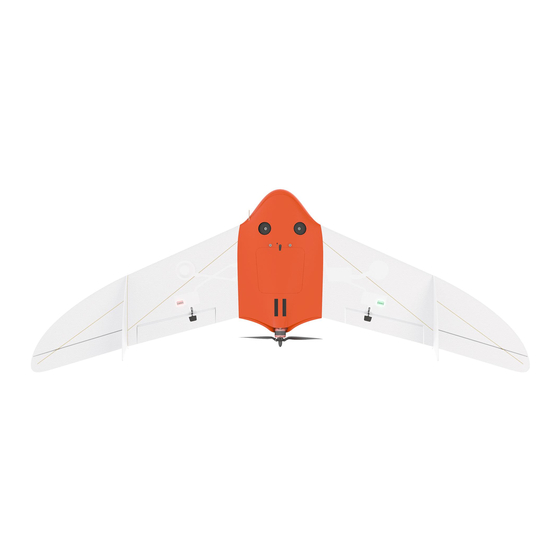
Main Information Geoscan 201 is an aerial survey system which consists of unmanned aerial vehicle (UAV), launcher and flight planning software. The system is designed for geolinked photography of objects and territories. Fields of application Obtained data can be used for: •…
-
Page 8: Kit
• Geoscan 201 UAV • Radio Modem • Radio Modem’s Pole • Battery Charger in Transport Case • Launcher in Transport Bag • UAV Transport Case • Folding Rack • Spare Parts • Documentation • Topcon B111 GNSS Receiver * •…
-
Page 9: Maintenance Service
Storage Geoscan 201 with battery should be stored in UAV transport case. The launcher should be stored in launcher’s bag. The storage place should be dry at the temperature range from +5 to 25 °С and relative humidity no more than 80% UAV service life —…
-
Page 10: Safety Rules
Follow these operating instructions for UAV safe use: • UAV launch and maintenance can be held only by persons, who trained accord- ing to the «Theoretical and practical training of Geoscan 201 unmanned aerial system control». • Follow dealer’s and/or manufacturer’s recommendations and instructions for use of the equipment, as given in this manual and received during operation period.
-
Page 11
“Arctic” modification: -40 to +20 °С. • Max wind speed: 12 m/s Geoscan 201 UAV is not intended to fly during rain, snow and other precipitation. The complex can’t fly below starting point altitude. in mountains conditions, find the lowest point of the area for flight mission start. The… -
Page 12: Uav Assembly
UAV Assembly Parts…
-
Page 13: Assembly
Assembly 1. Open UAV transport case, Take out UAV folding rack and place it on a flat surface. Take out fuselage from transport case and place it on UAV folding rack. 2. Remove the top cover by moving the pin, as shown in the picture. UAV top cover removing 3.
-
Page 14
4. Carefully put the wing on the mounting rods. Leave a gap between wing and fuselage for connect the connector. Put the connector in connector’s slot. Wing installing on mounting rods 5. Carefully move wing to fuselage and fast rubber locker. Install wing from the other side similarly. -
Page 15
6. Put middle and short-sized rods in wing as shown on the picture. Place fin and wingtip on rods as shown on the picture. Carefully put the wingtip on mounting rods and lock it by rubber locker. Similarly, install fin and wingtip from the other side. Fin and wingtip installing 7. -
Page 16
8. Place the battery by putting front catches in grooves and move the battery forward until that the rear catches clicks. The battery can be ejected by pressing side catchers. Battery installing 9. Close UAV top cover and make sure that locking pin hold it. Top cover closing Propeller blades, wing and elevon surfaces must not be damaged or cov- ered with any kind of paint, dirt or stickers. -
Page 17: Parashute
Parashute Parachute components: 1. Parachute compartment cover 5. Locking ring 2. Parachute dome 6. Long static line 3. Rigging lines’ pockets 7. Short static line with unhook ring system 4. Rigging lines…
-
Page 18: Parachute Folding
Parachute Folding Make sure that the Parachute dome, rigging Lines and their attachment to the dome are not damaged before laying the parachute. The dome and rigging lines should be dry and clean. Repack the parachute if the previous packaging is more than 10 days ago, or you were carrying UAV in an airplane.
-
Page 19
4. Fold the Dome in half and align the edges. Folding parashute dome in half second time As the result, the rigging lines should be collected in 4 bundles with 4 rigging lines in each. Result… -
Page 20
5. Fold the dome in half again. The pockets for laying the rigging lines must be outside. Folding rigging lines pockets out 6. Fold parashute dome as see on the picture. Folding parashute dome Make sure that in the process of laying the parachute rigging lines are not tangled. Straighten the lines out if it needs. -
Page 21
7. Put rigging lines in the pocket. Measure the length of the bundle of rigging lines exceeding the depth of the pocket. Fold the rigging lines bundle in half and stretch in the pocket, so that the bend of the bundle a few centimeters protruded from the opposite side of the pocket. -
Page 22
Result 9. Fold parashute dome as see a picture. Parashute dome folding… -
Page 23: Parachute Installing
Parachute Installing 1. Rotate UAV for the parachute compartment was on top. 2. Pick up the carabiner and straight rigging lines. 3. Put the short static line end in a carabiner as shown on the picture. Short static line end in carabiner 4.
-
Page 24
Short static line end turning into the ring of detaching system 5. Put short static line end in detach system ring and lock the loop between halfs of locker. Locking the loop in the lock Make sure that detach system is securely locked. -
Page 25
6. Make sure that detach system locker is securely locked: take the parachute dome and make some short sharp jerks. Detach lock check 7. Carefully pack the ropes of parachute system and rigging lines. 8. Pack the folded parachute. The base of the parachute with the ring was at the bottom of the parachute compartment. -
Page 26
9. Put the salient in parachute compartment’s cover rear in UAV body’s slot and hold down the cover. Lock the cover by servo horn. Check that the parashute compartment cover can opens. To do that just rotate servo horn. The parashute rigging lines must be free. 10. -
Page 27: Launcher
Launcher The launcher is a catapult, that speed up UAV at the launch. UAV delivery kit can include standard launcher with rubber cords tension system or «Arctic» launcher with springs tube. Standard Launcher Parts…
-
Page 28: Rules Of Rubber Cords Use
Rules of Rubber Cords Use • Check the condition of the rubber bands regularly. Replace the damaged ring by a spare ring from the spare parts kit, if damages are found. • Don’t keep the rubber cords stretched for a long time. Pull cords directly before placing UAV on the launcher.
-
Page 29: Assembly
Assembly 1. Take out the launcher parts from transport bag. 2. Unfold the launcher’s front supports. Make sure that they are securely fastened by locks. To fold the supports, pull the locks down. Supports unfolding 3. Attach the middle section of the launcher. Middle section attaching…
-
Page 30
4. Attach the section with reel. Section with reel attaching 5. Unfold rear section supports. Unfolding of rear section’s supports 6. Attach the rear section to the rest of the launcher. Insert the locking pin to secure the rear part and part with reel together. Rear part attaching… -
Page 31
7. Place the launcher on flat surface, so that the launch would happen against the wind direction. UAV should be launched ONLY against the wind direction. Otherwise, it can cause crash or obstacle collision. When the wind is not blowing at all, add extra coil of rubber bands from the repair kit on each side of the launcher. -
Page 32
10. Move the carriage down until it locks in the rear (you should hear 2 clicks). Before every launch make sure that the carriage free slides on rails. 11. Insert the safety pin into the launch mechanism. Release the winch stopper and unwind the tension Safety pin inserting 12. -
Page 33: Preparation To Uav Launch
14. Connect the other end of a rubber band to the winding line with a carabiner. The winding line must pass through the roller. The carbine must be clutched. 15. Attach the next rubber band in a same way. 16. Install the winch reel handle. Reel handle installing Preparation to UAV Launch Pull the rubber cords only after the successful launch preparation imme-…
-
Page 34: Arctic Launcher
Arctic Launcher «Arctic» Launcher is developed for launches in cold conditions. It uses wire springs system for carriage pulling. «Arctic» launcher Rules of Springs Use • Check the springs for a damage before using. • Install the springs directly before launch only. •…
-
Page 35: Assembly
Assembly 1. Take out the launcher parts from transport bag. 2. Spread out the supports on the launcher front part. Make sure that they are securely fastened by locks. To fold the supports pull the locks down. Supports installing 3. Attach the launcher’s middle part. Attaching of the launcher’s middle part…
-
Page 36
4. Attach the part with carriage detaching mechanism and put locking pin. Carriage detaching mechanism’s part installing 5. Spread out rear launcher’s supports. Rear supports spreading 6. Attach the rear part with reel to launcher and put locking pin. Rear part attaching… -
Page 37
7. Place the launcher on flat surface. The UAV must be launched against the wind. UAV launch is allowed only against the wind. It is strictly forbidden to launch the UAV in the direction of the wind. Otherwise, the UAV will not be able to correctly gain altitude and may collide with objects on the way. -
Page 38
10. Lift front of springs’ tube up, match the holes and lock springs’ tube by pin. Front tube side locking 11. Connect the holes in rear of springs’ tube the same way and lock it by pin. Rear tube side locking… -
Page 39
12. Lock springs’ tube by nut in rear. Tube locking by nut 13. Check springs state before install internal springs’ tube. They should be stretched without any entangles. Springs… -
Page 40
14. Place front springs’ tube in the bottom of front launcher’s part and lift it up to rear tube. Front springs’ tube placing 15. Connect front tube with rear tube by mounting screw and hold it by fingers. Tubes connection 16. -
Page 41
17. Lift the front end of front tube up and lock it by pin. Front tube locking 18. Place the carriage onto the guide of the launcher, so that it could slide along launcher rails. 19. Attach springs’ tube’s rope to carriage and safe system’s carabiner as shown on the picture. -
Page 42
20. Attach the rope and safe system’s carabiner from the other side as the step 19. Disassembly is performed in reverse sequence. It is important to attach safety system’s carabiners before springs’ ropes detaching from carriage. 21. Pull out the reel cable and lock cable’s carabiner on the carriage shaft. Carriage attaching… -
Page 43: Arctic Launcher Preparing To Start
4. Disconnect the carabiner from rear carriage shaft. The UAV can be placed on the launcher’s carriage. When you install UAV make sure that propeller blades are folded. UAV launch is impossible without Geoscan Planner flight mission and successful full pre-launch check. Please see Launch…
-
Page 44: Camera Settings
Camera Settings UAV camera number and type depends on delivery kit. This section describes recom- mended settings for aerial surveying in normal daylight conditions. Sony DSC-RX1RM2 Digital Camera Main Parts Please, carefully read Camera Operating instructions https:// www.sony.com/ electronics/ support/ res/ manuals/ 4579/ 45798651M.pdf to get full information about functions and control parts before change settings.
-
Page 45: Presets
Presets Geoscan UAVs are equipped with 2 presets for Sony DSC-RX1RM2 cameras. Use Mode Dial near ONOFF switcher to select preset for your needs. Preset 1 serves for shooting in normal daylight conditions. The aperture value is fixed, which provides fixed aperture for better ortophoto mosaic generation.
-
Page 46: Presets Restoring
Presets Restoring Settings of 1 and 2 presets can be restored, if you change them. For preset 1 restoring: • Set Mode Dial in position M (Manual aperture control). • Set shutter speed 1/1000 by Control Dial. • Select ISO — Auto in camera menu.. Press Menu button, go to Camera Settings (Tab
 and select Memory.
 -
Page 47: Sd Card Formatting
• In settings section set Power Saving Start Time — 30 min. (tab 2) и File Number — Reset (tab 5). Power saving start time File number reset SD Card Formatting • In Settings menu (tab 5) select Format. Format option All data on SD card will be deleted!
-
Page 48: Settings Reset
Settings Reset Reset of the camera will delete presets’ shooting settings (Presets 1 and 2)! • In Settings menu (tab 6) select Setting Reset «Setting reset» option Do not remove the battery during a reset process! • After camera reboot, you need to set Time zone and date, otherwise the settings will not be saved and this menu will appear at every turn on.
-
Page 49: Sony Dsc-Rx1 Digital Camera
Sony DSC-RX1 Digital Camera Main Parts Please, carefully read Camera Operating Instructions https:// www.sony.ru/ electronics/ support/ res/ manuals/ 4469/ 44695786M.pdf to get full information about functions and control parts before change settings. Basic camera control elements are shown on the picture: 1.
-
Page 50
To set camera soft parameters, push MENU button, then select parameters according to the following instructions. • In User settings menu (tab 1) turn off Automatic preview and set MOVIE Button — Movie mode only (tab 3). Turn off automatic preview Movie mode only •… -
Page 51: Sd Card Formatting
SD Card Formatting • Select MENU [Memory card] Format All memory card data will be deleted! Settings Reset Follow these steps to set default settings: • Select MENU [Settings menu] INITIALISATION Reset Do not remove the battery during a reset process! •…
-
Page 52: Sony A6000 Digital Camera
Sony A6000 Digital Camera Main Parts Please, carefully read Camera Operating Instructions https:// www.sony.ru/ electronics/ support/ res/ manuals/ 4532/ 45320554M.pdf to get full information about functions and control parts before change settings. Basic camera control elements are shown on the picture: AVCHD MENU 24.3 MEGAPIXELS…
-
Page 53: Sd Card Formatting
• In Custom Settings menu (tab 1) disable Automatic preview, turn on Lens-less Shut- ter (tab 3) and set MOVIE button — Video mode only (tab 6). Automatic preview off Turn on the shutter without a lens Video mode only for Movie button •…
-
Page 54: Micasense Rededge-Mx Camera
MicaSense RedEdge-MX Camera RedEdge-MX Camera is developed for multispectral imaging. Parts System included two main parts: 5-band camera and downwelling light sensor (DLS2). Camera 1. Control button 5. External Power/Trigger Port 2. LED 6. DLS/GPS-module Connection Port 3. SD-card slot 7.
-
Page 55: Led Indication
Pay attention, that you need portable compass for camera’s magnetic com- pass system calibration. LED Indication Camera’s LED indicates system state. DLS2 sensor’s LED is same. The table describes LED states: Color State Description The camera is ready for shooting: GPS connect is successful, 1 flash SD card storage is more than 2 GB 1 flash…
-
Page 56: Pre-Launch Check
Pre-launch Check 1. Turn UAV on. 2. Wait 15 sec for camera system initialization. 3. Check that DLS and camera LEDs are flashes green. Otherwise, check SD card file system. 4. Use Wi-Fi PC or phone to connect camera. Wi-Fi spot: rededgeRMXXXX-XX. password: micasense. 5.
-
Page 57: Calibration
Stream in Live View tab 11. Disable Streaming option. 12. Open Settings tab. 13. Check that Ext. Trigger is selected in Auto-Capture Mode field. 14. Make sure that Ext Trigger Mode is selected Rising Edge field. 15. In Advanced Configuration section in subsection PPS pin usage for Pin purpose field must be selected Output option.
-
Page 58
Magnetic Compass Calibration You need portable compass to calibrate camera’s inside magnetic compass system. The calibration should be performed away from metal objects and buildings. 1. Select DLS Сonfiguration in Settings tab. 2. Press Calibrate DLS Mag button to start magnetic compass calibration. 3. -
Page 59: Flight Project Settings
Flight Project Settings Set these recommended parameters in Geoscan Planner new project window (see more information in Geoscan Planner Software section): UAV Model — Geoscan 201 5S; Camera Model — MicaSense RedEdge-MX; GSD (cm) — 12; Forward Overlap (%) — 70;…
-
Page 60: Metadata Sync
3. Copy sort_rededge.bat script in RedEdge folder. This script will sort pictures in 5 folders. Each folder contains photos from one of spectral bands. The script is available for download here: https:// download.geoscan.aero/ site-files/ sort_rededge.bat File structure before script sorting 4. Launch sort_rededge.bat script as administrator.
-
Page 61
One calibration photo in one of the folders If RX1RM2 camera included in delivery kit, copy camera photos in RX1RM2 folder to sync metadata. 5. Connect UAV to Geoscan Planner software and select Georeference file in Flight tab. Georeference file… -
Page 62
GNSS metadata will be downloaded from UAV memory automatically. Set paths to RedEdge and RX1RM2 photos and press «Next» button. Paths to photos 6. Metadata will be attached to photos automatically. -
Page 63: Cameras’ Offsets
Cameras’ Offsets Onboard GNSS receiver is located inside UAV wind, and its center is away from camera sensor center. GNSS receiver offsets should be taken into account, when you create orthophoto mo- saic and 3D models. Coordinate axes Offsets of left camera slot Camera, direction A6000, down 0.505…
-
Page 64
Offsets of right camera slot Camera, direction A6000, down 0.374 -0.179 -0.04 DSC-RX1RM2, 15° 0.357 -0.181 -0.033 DSC-RX1RM2, down 0.368 -0.181 -0.032 Offsets of Sony DSC-RX1RM2 camera in center position Camera, direction DSC-RX1RM2, down 0.489 -0.175 -0.032 RedEdge-MX camera offsets of right slot Band Blue 0.480… -
Page 65: Battery And Charger
Battery and Charger Safety Rules Battery • DO NOT disassemble the battery. • DO NOT use chargers and cables, that not tested for capability with UAV battery by manufacturer. • DO NOT connect the battery to switched off charger. • DO NOT transport the battery in UAV body (in transport case only). •…
-
Page 66: Battery Charger
Battery Charger Control Unit Parts Control unit and power unit are placed in charger transport case. iCharger 3010B is installed as control unit. The picture below shows main parts of this device. iCharger 1. Cooling Fan 6. Dec — «Left» Button 2.
-
Page 67: Setup
Setup The charger is factory preseted. Use this section if you need to restore the settings: To open settings: • On PROGRAM SELECT main screen press Batt type/Stop button several times, to the moment, when screen will Settings section; • Press Start/Enter to open settings menu. Use Dec and Inc buttons to choose parameters and Start/Enter to select.
-
Page 68: Lipo Battery
LiPo Battery Control and Indication 1. Control button 4. LED status bar 2. Balance port 5. Charge port 3. Status LED Press Control button (1) to check battery status. Status LED (3) will light green and will change color to red. (and orange for «Arctic» batteries). Status LED color shows type of data, that indicated LED status bar (4): Green —…
-
Page 69: Battery Heating (For «Arctic» Battery)
Battery discharge speed depends on UAV motor speed. The autopilot system is change speed level depends on telemetry sensors and UAV flight task. For example, for mini- mizing of battery discharge you can create field of aerial survey with minimum points of UAV rotate in flight.
-
Page 70: Battery Connecting
Battery Connecting 1. Check charge settings. 2. Connect balance cable to the battery. 3. Connect charge cable to the battery. 4. Long press Start/Enter button, until the charger will change status to Battery Check. After successful cells check battery charger will start charging process automatically. You can use car’s 12 V battery as charger power source.
-
Page 71: Geoscan Planner Software
Geoscan Planner Software Geoscan Planner software allows to configure UAV and create flight projects for aerial survey of areas and single objects. System Requirements Minimum System Requirements Operating system MS Windows 7,8,10 Intel Core i3 4 Gb GPU Type Dedicated…
-
Page 72: New Project
New Project 1. Install and launch Geoscan Planner software. 2. Enter your login/password in authentication window and create new project by press New Project button. Authentication window New Project button 3. Enter a project name and shooting parameters in the new project window.
-
Page 73: Aerial Surveying
Aerial Surveying Aerial surveying is a polygon surveying. User sets vertices of the polygon (more than 3) and the software will automatically calculates a flight route. 1. Press Create aerial surveying on the toolbar. Create aerial surveying 2. Click on the map to set vertexes of aerial survey area. The program will automati- cally calculate the flight route.
-
Page 74
To remove the vertex: 1. Right click on the vertex. 2. Select Delete vertex. Delete vertex Change Flight Route Direction The need to change a flight route may be caused, if the force and direction of the wind are unfavorable (strong wind along the flight route of the polygon). Right-click on the polygon and select the option Optimization «Direction»… -
Page 75
One of the vertices of the polygon will be colored gray. Use the point’s slider to set the flight route direction. Correction of the flight direction A new flight route through the polygon in a selected direction will be generated au- tomatically. -
Page 76
Start Point Changing Follow these steps to change the polygon entry point: 1. Select a polygon. Selected polygon 2. Select vertex, right click and choose Make start point here. Context menu of a point The selected point will be marked with a flag… -
Page 77: Linear Surveying
Linear Surveying Create linear surveying tool allows to create a flight route along linear objects, such as: rivers, roads, oil pipelines, etc. . 1. Press Create linear surveying button on the toolbar. Create linear surveying button 2. Single clicks to set a path around an object. The program will automatically gen- erate flight route.
-
Page 78: Hop
Fight by pre-seted route with a seted altitude. It is mainly used for passing around point objects (i.e. high objects) and topographic inequality. Click on the icon Create hop on the toolbar. Create hop button 2. Specify the flight route by single- clicking.
-
Page 79: Waiting Point
Waiting Point Create waiting point tool allows to hold UAV on selected map point. 1. Press Create waiting point on the toolbar. Waiting point button 2. Click mouse button on the map to set waiting point. You can activate more options an expert mode: set delay point height, waiting time, direction, wind measurement and endless devay functions.
-
Page 80
Infinite waiting option sets holding point in the air (point will be hold until the low battery charge will trigger automatic return to start point). The waiting point color will change to deep blue. Infinite waiting point We recommend to set the waiting point with wind measurement before each flight element at the height of the flight element, especially if they are located a large distance from each other. -
Page 81: Landing Point
Landing Point Create landing point tool is used to set the UAV landing point. It is necessary to land UAV at the flight mission end. Choose open dry place without trees and other barriers for landing. Check the wing direction at landing route and correct land trajectory if it needs. 1.
-
Page 82: Connection Settings
Connection Settings Radio Modem Connection The radio modem is used to load a flight task into the autopilot memory, set up and semi-automatic control UAV flight up to 40 km, if a flight zone doesn’t have any signal barriers. This section describes how to set up wireless connection between the UAV and laptop.
-
Page 83
Adding a new device If UAV is not detected reconnect radio modem by right-click on the MdmDisp icon and select Reconnect. in the context menu. If connection is failed: • Check connection of the radio modem to laptop’s USB socket. •… -
Page 84: Uav Connecting To Geoscan Planner
UAV Connecting to Geoscan Planner 1) Select Connect to the UAV — Search… in Flight tab. UAV connection 2) Select connection type in MdmDisp. Set IP-adress — localhost. In UAV list set UAV — Port 1. Connection settings The settings will be automatically saved. At the next connections turn on the UAV power and use Connect UAV button on the toolbar.
-
Page 85: Pre-Launch Check
Pre-launch Check Launch Start Preparing Wizard. Start Preparing Wizard launch button Follow the instructions of the Start preparing Wizard (most tests are runned automatically). On Parameters stage set: Parashute autodeatach radius (m) — radius around landing point, that trigged parashute autodetach af- ter landing.
-
Page 86: Flight
Flight Press Start button. Start button UAV autopilot will change mode to start. The telemetry panel will display CATAPULT mode. Catapult mode It is necessary to switch the UAV to start mode only after placing it on the launcher. It is forbidden to take and move the UAV after switching to CATAPULT mode.
-
Page 87: Landing
Landing Press Go to landing button to start UAV landing. «Go to landing» button The automatic landing slowdown is triggered by the barometric altitude. It is not recommended to indicate the landing point at a location that differs much in elevation from takeoff point.
-
Page 88: Launch
1. Charge UAV battery and make sure, that battery’s LED status bar showed full charge level (see Battery and Charger section for details). 2. Create and save new project in Geoscan Planner software to upload it directly before flight (see Geoscan Planner Software section for details).
-
Page 89
11. Open flight project in Geoscan Planner software and connect UAV. (see Connection Settings section for details) 12. Launch Start Preparing Wizard and complete all steps. On launch preparing remove lens caps from cameras, install UAV on launcher and pull rubber cords (springs for «Arctic»… -
Page 90: Uav Disassembly
UAV Disassembly 1, Open UAV top cover. 2, Turn UAV power off and eject the battery. 3, Eject SD card from cameras to to process shooting results. 4, Place UAV on folding rack. 5, Unclasp rubber locks on the wingtips and pull them off the rods. Remove the rods and fins.
-
Page 91: Appendix
Appendix Specifications UAV Type Fixed-wing Motor Type Electric Brushless Max. Flight Speed 130 km/h Max. Survey Area per Flight 7-22 km Max. Wind Resistance 12 m/s Wingspan 2,22 m Max. Flight Altitude 4000 m Max. Flight Time 180 min Max. Flight Distance 210 km Max.
-
Page 92
LiPo Battery Cells Capacity 34 000 mA·h Recommended Charge Current 10 A Max. Charge Current 17 A Max. Voltage 21 V Normal Voltage 18,5 V Min. Voltage 15 V Weight 3,1 kg Topcon B111 GNSS Receiver * Number of channels 226 universal tracking channels Acquisition time (hot/cold start) <15 / <44 sec… -
Page 93
Sony DSC-RX1RM2 Digital Camera * Sensor Full-frame CMOS Exmor R (35.9×24 mm) Number of Pixels 43,6 MP Shutter Central Aperture f/2-22 ISO Range 100-102400 Shutter Speed from 1/4000 to 30 sec Sony A6000 Digital Camera * Sensor CMOS Number of Pixels 24,3 MP Shutter Focal… -
Page 94
Battery Charger’s Case Body Material Polypropylene Protection Class IP67 Transport Handle Wheeled Dimensions 49.9 x 39.3 x 19.1 cm UAV Transport Case Body Material Injection Molded HPX™ high performance resin Protection Class IP67 Extendable Handle Wheeled Dimensions 79.5 x 51.8 x 31 cm… -
Page 95
Geoscan Group, 2021…
 and select Memory.
 Беспилотный летательный аппарат (БПЛА) Геоскан 201 предназначен для выполнения аэрофотосъемочных работ на обширных территориях. За один вылет он позволяет снять до 16 квадратных километров с разрешением 4 см на пиксель. Двух батарей, входящих в комплект, хватает на непрерывную работу в течение всего рабочего дня.
Геоскан 201 имеет прочный и легкий корпус из композитных материалов, а также составные крылья особой конструкции из легкого и прочного вспененного полипропилена. Разборная конструкция крыла позволила добиться компактности размещения элементов при транспортировке. Рабочий комплект может перевозиться в багажнике автомобиля или купе поезда.
Электронная начинка БПЛА Геоскан 201 (авионика) разработана компанией Геоскан и рассчитана на максимальную надежность при любых нагрузках. После сборки все компоненты БПЛА проходят тщательное тестирование.
Во время полета Геоскан 201 управляется полностью автоматически согласно загруженному полетному заданию. Запуск осуществляется с помощью катапульты, а посадка выполняется на парашюте в районе точки запуска.
Геоскан 201 является одним из самых надежных БПЛА в своем классе. Его безопасность подтверждена тысячами взлетов и посадок. С помощью наземной станции управления можно контролировать состояние летательного аппарата на всех этапах полета. В модем связи встроена кнопка экстренного выброса парашюта, которая сработает даже при выходе из строя наземной станции управления. Автопилот постоянно отслеживает состояние планера во время полета и в случае нештатной ситуации сам вернет его в точку запуска.
БПЛА Геоскан 201 способен нести до 3-х полезных нагрузок одновременно и выполнять синхронную запись данных нескольких сенсоров.
В качестве полезной нагрузки используется фотокамера Sony DSC-RX1, имеющая полноразмерную матрицу 24.7 Мпикс, 35-мм объектив и центральный затвор.
Бортовой спутниковый приемник Topcon позволяет выполнять привязку модели с точностью в 5-10 см (в зависимости от активированных опций) без применения наземных опознаков.
Дополнительная полезная нагрузка:
- Мультиспектральная фотокамера (на базе Sony A5000);
- ГНСС приемник (Одночастотный (L1) или двухчастотный (L1, L2), односистемный (GPS) или двухсистемный (GPS/ГЛОНАСС).
Дополнительное оборудование:
- Ноутбук в защищенном исполнении;
- Дополнительное беспилотное воздушное судно Геоскан 201 (планер, электроника, бортовой блок связи управление/телеметрия, защитный контейнер IP67, ЗИП);
- Модификация «Арктика» (расширение температурного диапазона от -40 до +20 ).
Дополнительное программное обеспечение:
- PhotoScan Professional;
- ГИС Спутник;
- ГИС Спутник Агро;
- MAGNET Office Tools Adv. Post processing.
Geoscan Planner
Управление без пультов и навыков пилотирования.
Программное обеспечение GеoScan Planner, позволяет строить полетные задания площадных и линейных объектов, использовать различные режимы полета (полет по точкам, полет с учетом рельефа и др.), загружать kml и kmz файлы, использовать различные картографические подложки.
Достаточно выделить область съемки на карте или загрузить из файла и программа сама построит полетное задание, отправит его на беспилотник и проконтролирует качественное выполнение полета.
Техническая поддержка
Пути решения типовых проблем и ответы на самые частые вопросы пользователей представлены на портале технической поддержки.
Если в предложенных статьях не удалось найти нужное Вам решение, или оно по какой-то причине не сработало, свяжитесь с нами удобным для Вас способом.
Инструкции по комплексам
Вопрос / ответ
В нашей базе собраны самые популярные вопросы по Agisoft Metashape, ГИС Спутник, Magnet Tools, Geoscan Planner и многое другое.
Перейти в базу знаний

Name already in use
A tag already exists with the provided branch name. Many Git commands accept both tag and branch names, so creating this branch may cause unexpected behavior. Are you sure you want to create this branch?
1
branch
0
tags
Code
-
Use Git or checkout with SVN using the web URL.
-
Open with GitHub Desktop
-
Download ZIP
Latest commit
Files
Permalink
Failed to load latest commit information.
Type
Name
Latest commit message
Commit time
Документация Геоскан 201
Аэрофотосъемочный комплекс, включающий в себя беспилотное воздушное судно (БВС) типа «летающее крыло», пусковую установку – катапульту и наземную станцию управления.
Предназначен для получения геопривязанных фотографий объектов и площадной аэрофотосъёмки.
Полученные с использованием комплекса материалы могут использоваться для:
* создания ортофотопланов масштаба 1:500 – 1:2000
* трехмерного моделирования участка местности
* создания карт высот местности
* вычисления объемов пород в карьерах и насыпных объектах
* обследования состояния объектов инфраструктуры, дорожного полотна
* инвентаризации лесов и посевов
* оценки ущерба и планировании аварийно-спасательных работ при ЧС, таких как наводнения, оползни и пожары
Presets Restoring . . . . . . . . . . . . . . . . . . . . . . . . . . . . . . . .
SD Card Formatting . . . . . . . . . . . . . . . . . . . . . . . . . . . . . . .
Settings Reset . . . . . . . . . . . . . . . . . . . . . . . . . . . . . . . . . .
Main Parts . . . . . . . . . . . . . . . . . . . . . . . . . . . . . . . . . . . .
Camera Settings . . . . . . . . . . . . . . . . . . . . . . . . . . . . . . . . .
SD card Formatting . . . . . . . . . . . . . . . . . . . . . . . . . . . . . . .
Parts . . . . . . . . . . . . . . . . . . . . . . . . . . . . . . . . . . . . . . . .
LED Indication . . . . . . . . . . . . . . . . . . . . . . . . . . . . . . . . . .
Camera Settings . . . . . . . . . . . . . . . . . . . . . . . . . . . . . . . . .
Before Power On . . . . . . . . . . . . . . . . . . . . . . . . . . . .
Pre-launch Check . . . . . . . . . . . . . . . . . . . . . . . . . . . .
Calibration . . . . . . . . . . . . . . . . . . . . . . . . . . . . . . . .
Metadata Sync . . . . . . . . . . . . . . . . . . . . . . . . . . . . . . . . . .
Cameras’ Offsets . . . . . . . . . . . . . . . . . . . . . . . . . . . . . . . . . . . .
Safety Rules . . . . . . . . . . . . . . . . . . . . . . . . . . . . . . . . . . . . . . .
Battery Charger . . . . . . . . . . . . . . . . . . . . . . . . . . . . . . . . . . . . .
Control Unit Parts . . . . . . . . . . . . . . . . . . . . . . . . . . . . . . . .
Setup . . . . . . . . . . . . . . . . . . . . . . . . . . . . . . . . . . . . . . .
LiPo Battery . . . . . . . . . . . . . . . . . . . . . . . . . . . . . . . . . . . . . . .
Battery Connecting . . . . . . . . . . . . . . . . . . . . . . . . . . . . . . . . . . .
Battery Recycling . . . . . . . . . . . . . . . . . . . . . . . . . . . . . . . . . . . .
System Requirements . . . . . . . . . . . . . . . . . . . . . . . . . . . . . . . . .
New Project . . . . . . . . . . . . . . . . . . . . . . . . . . . . . . . . . . . . . . .
Aerial Surveying . . . . . . . . . . . . . . . . . . . . . . . . . . . . . . . . .
Linear Surveying . . . . . . . . . . . . . . . . . . . . . . . . . . . . . . . . .
Hop . . . . . . . . . . . . . . . . . . . . . . . . . . . . . . . . . . . . . . . . . . . .
Waiting Point . . . . . . . . . . . . . . . . . . . . . . . . . . . . . . . . . . . . . .
Landing Point . . . . . . . . . . . . . . . . . . . . . . . . . . . . . . . . . . . . . .
3
46
47
48
49
49
49
51
51
52
52
52
53
54
54
55
55
55
56
57
59
60
63
65
65
66
66
67
68
68
69
70
70
70
71
71
72
73
77
78
79
81