Популярные файлы
-

Магнитола WK(WH) 2008+ (руководство)
Автор
AG
-
1 505
-
9
Руководство на русском по эксплуатации мультимедийной системы REZ, устанавливаемой на Jeep grand Cherokee WK(WH) 2008+
- Подробнее
- Скачать
-
-
Снятие передней юбки бампера на WK2
Автор
sdolina
-
609
-
2
Как снять и поставить переднюю юбку бампера WK2 без снятия бампера
- Подробнее
- Скачать
-
-
Grand Cherokee 2011-2013 Инструкция к МАФОНУ (рус)
Автор
Danko
-
2 853
-
17
Руководство по эксплуатации мультимедийной системы Jeep Grand Cherokee WK2 на русском языке
- Подробнее
- Скачать
-
-
Руководство Jeep Liberty/Cherokee KJ 2001-2007
Автор
Stason4x4
-
3 252
-
26
Руководство по эксплуатации Jeep Liberty/Cherokee KJ (2001-2007). Приведено описание моделей с бензиновыми двигателями (2.4L, 3.7L) и с дизельным двигателем (2.8L). Руководство на русском языке.
- Подробнее
- Скачать
-


- Manuals
- Brands
- Jeep Manuals
- Automobile
- GRAND CHEROKEE 2021
- Owner’s manual
-
Contents
-
Table of Contents
-
Bookmarks
Quick Links
2021 GRA ND C H ER OKEE
OWN ER’S MA N UA L
Related Manuals for Jeep GRAND CHEROKEE 2021
Summary of Contents for Jeep GRAND CHEROKEE 2021
-
Page 1
2021 GRA ND C H ER OKEE OWN ER’S MA N UA L… -
Page 2
This Owner’s Manual illustrates and describes the operation of features and equipment that are either standard or optional on this vehicle. This manual may also include a description of features and equipment that are no longer available or were not ordered on this vehicle. -
Page 3: Table Of Contents
TABLE OF CONTENTS INTRODUCTION ……………………..8 GETTING TO KNOW YOUR VEHICLE ………………15 GETTING TO KNOW YOUR INSTRUMENT PANEL …………79 STARTING AND OPERATING ………………..99 MULTIMEDIA ……………………..170 SAFETY ……………………….255 IN CASE OF EMERGENCY ………………..308 SERVICING AND MAINTENANCE ………………329 TECHNICAL SPECIFICATIONS ……………….. 385 CUSTOMER ASSISTANCE …………………
-
Page 4
INTRODUCTION UCONNECT VOICE RECOGNITION ……40 DOORS…………..23 Manual Door Locks……..23 Introducing Voice Recognition….40 Symbols Key…………9 Power Door Locks ……..24 Basic Voice Commands ……41 ROLLOVER WARNING ……….. 9 Keyless Enter-N-Go — Passive Entry ..24 Get Started……….. 41 WARNINGS AND CAUTIONS …….10 Additional Information……… -
Page 5
INTERIOR STORAGE AND EQUIPMENT ….. 62 To Lock/Close The Liftgate ……73 EXTERIOR LIGHTS……….48 Power Liftgate — If Equipped ….. 74 Headlight Switch ……… 48 Storage …………62 Cargo Area Features ……..75 Multifunction Lever ……..49 USB/AUX Control — If Equipped….63 ROOF LUGGAGE RACK —… -
Page 6
STARTING AND OPERATING PARKSENSE FRONT/REAR PARK ASSIST QUADRA-LIFT — IF EQUIPPED……115 Description……….115 SYSTEM — IF EQUIPPED ……..134 STARTING THE ENGINE ……..99 Air Suspension Modes…….117 ParkSense Sensors ……..135 Automatic Transmission……99 Instrument Cluster Display Messages ..117 ParkSense Display……..135 Normal Starting ……….. -
Page 7
TRAILER TOWING ……….151 UCONNECT SETTINGS……..171 CONNECTED SERVICES FAQs ……237 Common Towing Definitions …..151 Customer Programmable Features ..171 Connected Services SOS FAQs ….237 Trailer Hitch Classification ……153 UCONNECT INTRODUCTION ……187 Connected Services Remote Door Lock/ Trailer Towing Weights (Maximum Trailer Unlock FAQs ……….238 System Overview ……..187 Weight Ratings)……….154… -
Page 8
UCONNECT REAR SEAT ENTERTAINMENT OCCUPANT RESTRAINT SYSTEMS ….275 REFUELING IN EMERGENCY – (RSE) SYSTEM — IF EQUIPPED……246 Occupant Restraint Systems Features..275 IF EQUIPPED …………321 Important Safety Precautions….275 Getting Started………..246 IF YOUR ENGINE OVERHEATS ……321 Seat Belt Systems ……..276 Dual Video Screen ……..247 MANUAL PARK RELEASE ……… -
Page 9
STORING THE VEHICLE……..382 VEHICLE MAINTENANCE ……..336 FLUID CAPACITIES……….389 Engine Oil ……….336 BODYWORK …………382 ENGINE FLUIDS AND LUBRICANTS ….390 Engine Oil Filter……….337 Protection From Atmospheric Agents..382 CHASSIS FLUIDS AND LUBRICANTS ….391 Engine Air Cleaner Filter……338 Body And Underbody Maintenance ..382 CUSTOMER ASSISTANCE Air Conditioner Maintenance ….339 Preserving The Bodywork……382… -
Page 10: Introduction
For this reason, it reserves the right to make changes to the model described for technical and/or commercial reasons. For further information, contact an authorized dealer. When it comes to service, remember that authorized dealers know your Jeep vehicle best, have factory-trained technicians and genuine MOPAR® parts, and care about your satisfaction.
-
Page 11: Symbols Key
SYMBOLS KEY ROLLOVER WARNING Utility vehicles have a significantly higher rollover rate than other types of These statements are against vehicles. This vehicle has a higher ground clearance and a higher center of operating procedures that could result gravity than many passenger vehicles. It is capable of performing better in a WARNING! in a collision, bodily injury and/or wide variety of off-road applications.
-
Page 12: Warnings And Cautions
VEHICLE MODIFICATIONS/ALTERATIONS Red Warning Lights WARNING! Door Open Warning Light Ú page 89 Any modifications or alterations to this vehicle could seriously affect its roadworthiness and safety and may lead to a collision resulting in Electric Power Steering (EPS) Fault serious injury or death.
-
Page 13
Yellow Warning Lights Red Warning Lights Service Adaptive Cruise Control Oil Temperature Warning Light (ACC) Warning Light Ú page 90 Ú page 91 Anti-Lock Brake System (ABS) Seat Belt Reminder Warning Light Warning Light Ú page 90 Ú page 91 Transmission Temperature Electronic Stability Control (ESC) Warning Light —… -
Page 14
Yellow Indicator Lights Yellow Warning Lights Air Suspension Active Indicator Low Washer Fluid Warning Light — If Equipped Light — If Equipped Ú page 94 Ú page 92 Air Suspension Entry/Exit Indicator Engine Check/Malfunction Light — If Equipped Indicator Warning Light (MIL) Ú… -
Page 15
Yellow Indicator Lights Green Indicator Lights 4WD Low Indicator Light — If LaneSense Indicator Light — If Equipped Equipped Ú page 95 Ú page 96 NEUTRAL Indicator Light — If Park/Headlight On Indicator Light Equipped Ú page 95 Ú page 95 Snow Mode Indicator Light Green Indicator Lights Ú… -
Page 16
White Indicator Lights Blue Indicator Lights Adaptive Cruise Control (ACC) High Beam Indicator Light Ready Light — If Equipped Ú page 97 Ú page 96 Cruise Control Ready Indicator Light Ú page 96 Hill Descent Control (HDC) Indicator Light — If Equipped Ú… -
Page 17: Getting To Know Your Vehicle
GETTING TO KNOW YOUR VEHICLE KEYS 1 — Unlock Button 2 — Liftgate Button 3 — Emergency Key Your vehicle is equipped with a key fob which 4 — Lock Button supports Passive Entry, Remote Keyless Entry 5 — Remote Start Button (RKE), Keyless Enter-N-Go (if equipped), 6 —…
-
Page 18
GETTING TO KNOW YOUR VEHICLE NOTE: Perchlorate Material — special handling may 2. Separate the key fob halves using a #2 flat apply. See www.dtsc.ca.gov/hazard- blade screwdriver or a coin, and gently pry If the vehicle is unlocked with the key fob, … -
Page 19: Sentry Key
GETTING TO KNOW YOUR VEHICLE 3. Remove the back cover to access and or activated. Operation is automatic, regardless WARNING! replace the battery. When replacing the of whether the vehicle is locked or unlocked. battery, match the (+) sign on the battery to Always remove the key fobs from the …
-
Page 20: Ignition Switch
GETTING TO KNOW YOUR VEHICLE ON/RUN CAUTION! Driving position The Sentry Key Immobilizer system is not All the electrical devices are available (e.g. compatible with some aftermarket remote climate controls, etc.) starting systems. Use of these systems may result in vehicle starting problems and loss of START security protection.
-
Page 21: Remote Start — If Equipped
GETTING TO KNOW YOUR VEHICLE NOTE: WARNING! CAUTION! Obstructions between the vehicle and key fob When exiting the vehicle, always remove An unlocked vehicle is an invitation for may reduce this range. the key fob from the vehicle and lock your thieves.
-
Page 22: To Exit Remote Start Mode
GETTING TO KNOW YOUR VEHICLE To drive the vehicle, push the unlock button, All of the following conditions must be met WARNING! and with a valid Keyless Enter-N-Go key fob in before the engine will Remote Start: the vehicle, press the brake pedal and place the Do not start or run an engine in a closed …
-
Page 23: Remote Start Front Defrost Activation — If Equipped
GETTING TO KNOW YOUR VEHICLE — Once the ignition is placed in the ON/RUN Manual Temperature Control (MTC) — If EMOTE TART OMFORT YSTEMS position, the climate controls will resume the Equipped QUIPPED previously set operations (temperature, blower In ambient temperatures at 40°F (4.5°C) or …
-
Page 24: Remote Start Windshield Wiper De-Icer Activation — If Equipped
GETTING TO KNOW YOUR VEHICLE The instrument cluster display message stays For vehicles equipped with Keyless Entry, EMOTE TART INDSHIELD IPER active until the ignition is placed in the ON/RUN make sure the vehicle’s keyless ignition –I — I CTIVATION QUIPPED position Ú…
-
Page 25: Rearming Of The System
GETTING TO KNOW YOUR VEHICLE NOTE: system will arm, regardless of whether you are AMPER LERT in the vehicle or not. If you remain in the vehicle The driver’s door key cylinder cannot arm or If something has triggered the vehicle security …
-
Page 26: Power Door Locks
GETTING TO KNOW YOUR VEHICLE If the door lock switch is pushed while the OWER OCKS WARNING! ignition is in ACC or ON/RUN and the driver’s The power door lock switches are located on For personal security and safety in the door is open, the doors will not lock.
-
Page 27
GETTING TO KNOW YOUR VEHICLE Passive Entry Unlock initiates illuminated Frequency Operated Button Integrated Key approach (low beams, license plate lamp, (FOBIK-Safe) position lamps) for whichever time duration To minimize the possibility of unintentionally is set between 0, 30 (default), 60 or 90 locking a Passive Entry key fob inside your seconds. -
Page 28
GETTING TO KNOW YOUR VEHICLE When any of these situations occur, after all NOTE: open doors are shut, the FOBIK-Safe search will After pushing the door handle button, you be executed. If it finds a Passive Entry key fob must wait two seconds before you can lock or inside the car, the car will unlock and alert the unlock the doors, using either Passive Entry… -
Page 29: Locking The Doors With One Or More Doors Open
GETTING TO KNOW YOUR VEHICLE — I NOTE: To Lock The Liftgate UTOMATIC OCKS With a valid Passive Entry key fob within 5 ft QUIPPED If the vehicle is unlocked, the liftgate will (1.5 m) of the liftgate, push the Passive Entry open with the handle and no key fob is The auto door lock feature default condition is lock button located on the outside liftgate door…
-
Page 30: Steering Wheel
GETTING TO KNOW YOUR VEHICLE STEERING WHEEL For emergency exit with the system engaged, pull up on the door lock knob (unlocked posi- tion), roll down the window, and open the ANUAL ELESCOPING TEERING door with the outside door handle. —…
-
Page 31: Power Tilt/Telescoping Steering
GETTING TO KNOW YOUR VEHICLE — I the steering column, pull the steering wheel EATED TEERING HEEL outward or push it inward as desired. To lock QUIPPED the steering column in position, push the The steering wheel contains a heating element control upward until fully engaged.
-
Page 32: Driver Memory Settings — If Equipped
GETTING TO KNOW YOUR VEHICLE Power tilt and telescopic steering column (if ROGRAMMING EMORY EATURE WARNING! equipped) To create a new memory profile, perform the Persons who are unable to feel pain to the A set of desired radio station presets following: …
-
Page 33: Linking And Unlinking The Key Fob To
GETTING TO KNOW YOUR VEHICLE SEATS NOTE: INKING NLINKING Your key fob can be unlinked to your memory EMORY Seats are a part of the Occupant Restraint settings by pushing the set (S) button, followed System of the vehicle. Your key fobs can be programmed to recall one by pushing the unlock button on the key fob of two saved memory profiles by pushing the within 10 seconds.
-
Page 34: Manual Adjustment (Front Seats) — If
GETTING TO KNOW YOUR VEHICLE ANUAL DJUSTMENT RONT EATS WARNING! (Continued) — I QUIPPED Seats should be adjusted before fastening the seat belts and while the vehicle is WARNING! parked. Serious injury or death could result Adjusting a seat while the vehicle is moving from a poorly adjusted seat belt.
-
Page 35: Manual Adjustment (Rear Seats)
GETTING TO KNOW YOUR VEHICLE ANUAL DJUSTMENT EATS WARNING! WARNING! Do not ride with the seatback reclined so that Adjusting a seat while the vehicle is moving WARNING! is dangerous. The sudden movement of the the shoulder belt is no longer resting against Do not pile luggage or cargo higher than the your chest.
-
Page 36
GETTING TO KNOW YOUR VEHICLE NOTE: To Raise Rear Seat WARNING! Do not fold the 60% rear seat down with the Raise the rear seatback and lock it into place. If Do not ride with the seatback reclined so that left outboard or rear center seat belt buckled. -
Page 37: Power Adjustment (Front Seats) — If Equipped
GETTING TO KNOW YOUR VEHICLE ) — Adjusting The Seat Up Or Down OWER DJUSTMENT RONT EATS WARNING! (Continued) The height of the seats can be adjusted up or QUIPPED Seats should be adjusted before fastening down by using the power seat switch. The seat Some models may be equipped with eight-way the seat belts and while the vehicle is will move in the direction of the switch.
-
Page 38: Heated Seats — If Equipped
GETTING TO KNOW YOUR VEHICLE — I the lumbar support. Pushing upward or When you place the vehicle’s ignition in the EATED EATS QUIPPED OFF position, the driver seat will move about downward on the switch will raise and lower the position of the support.
-
Page 39: Front Ventilated Seats — If Equipped
GETTING TO KNOW YOUR VEHICLE — I Front Heated Seats — If Equipped Rear Heated Seats — If Equipped RONT ENTILATED EATS The front heated seats control buttons are On some models, the two rear outboard seats QUIPPED located within the Uconnect system. You can may be equipped with heated seats.
-
Page 40: Head Restraints
GETTING TO KNOW YOUR VEHICLE head restraint. The AHRs will be split in two For comfort, the Active Head Restraints can be ESTRAINTS halves, with the front half being soft foam and tilted forward and rearward. To tilt the head Head restraints are designed to reduce the risk trim, the back half being decorative plastic.
-
Page 41
GETTING TO KNOW YOUR VEHICLE NOTE: WARNING! (Continued) The head restraints should only be removed Active Head Restraints may be deployed if by qualified technicians, for service purposes they are struck by an object such as a hand, only. -
Page 42: Uconnect Voice Recognition
GETTING TO KNOW YOUR VEHICLE NOTE: WARNING! For proper routing of a Child Seat Tether, see ALL the head restraints MUST be rein- Ú page 275. stalled in the vehicle to properly protect the occupants. Follow the re-installation WARNING! instructions above prior to operating the A loose head restraint thrown forward in a …
-
Page 43: Basic Voice Commands
GETTING TO KNOW YOUR VEHICLE Each time you give a Voice Command, you ASIC OICE OMMANDS DDITIONAL NFORMATION must first push the Voice Recognition (VR) The basic Voice Commands below can be given © 2020 FCA US LLC. All rights reserved. Mopar button, wait until after the beep, then say at any point while using your Uconnect system.
-
Page 44: Mirrors
GETTING TO KNOW YOUR VEHICLE MIRRORS Automatic Dimming Mirror — If Equipped CAUTION! The rearview mirror can be adjusted up, down, To avoid damage to the mirror during NSIDE EARVIEW IRROR left, and right. The mirror should be adjusted to cleaning, never spray any cleaning solution center on the view through the rear window.
-
Page 45: Outside Mirrors
GETTING TO KNOW YOUR VEHICLE Sun Visor “Slide-On-Rod” Feature — If OWER IRRORS WARNING! Equipped The power mirror switch is located on the Vehicles and other objects seen in an outside The sun visor “Slide-On-Rod” feature allows for driver’s side door trim panel. convex mirror will look smaller and farther additional flexibility in positioning the sun visor The power mirror controls consist of mirror…
-
Page 46: Power Folding Outside Mirrors
GETTING TO KNOW YOUR VEHICLE — Automatic Power Folding Mirrors The mirrors come out of the unfolded posi- OWER OLDING UTSIDE IRRORS tion. QUIPPED When the Automatic Fold Mirrors feature is enabled, the exterior mirrors will fold in when The mirrors shake and vibrate at normal …
-
Page 47: Universal Garage Door Opener
GETTING TO KNOW YOUR VEHICLE ® REVERSE. If the vehicle is equipped with The HomeLink® buttons that are located in RASING memory settings, this feature will be linked to the overhead console or sunvisor designate HANNELS the three different HomeLink® channels. the programmable settings.
-
Page 48: Programming Homelink® To A Garage Door Opener
GETTING TO KNOW YOUR VEHICLE Rolling Code Devices NOTE: Rolling Code Garage Door Opener Final Steps All HomeLink® buttons are programmed using To determine if your device has a rolling code, a NOTE: this procedure. You do not need to erase all good indicator is its manufacturing date.
-
Page 49: Miscellaneous Device
GETTING TO KNOW YOUR VEHICLE ® T Non-Rolling Code Garage Door Opener Final 1. Place the ignition in the ON/RUN position, ROGRAMMING Steps without starting the engine. ISCELLANEOUS EVICE 1. Push and hold the programmed 2. Push and hold the desired HomeLink® Follow the procedure on programming HomeLink®…
-
Page 50: Reprogramming A Single Homelink
GETTING TO KNOW YOUR VEHICLE EXTERIOR LIGHTS It may be helpful to unplug the device during the NOTE: cycling process to prevent possible overheating If the indicator light stays on constantly, of the garage door or gate motor. EADLIGHT WITCH programming is complete and the garage door/device should activate when the…
-
Page 51: Multifunction Lever
GETTING TO KNOW YOUR VEHICLE To turn on the headlights, rotate the headlight Once the turn signal is no longer active, the ULTIFUNCTION EVER switch clockwise. When the headlight switch is DRL lamp will illuminate. The multifunction lever is located on the left on, the parking lights, taillights, license plate The DRLs function may be disabled through side of the steering column.
-
Page 52: Flash-To-Pass
GETTING TO KNOW YOUR VEHICLE — I NOTE: UTOMATIC EADLIGHTS QUIPPED UTOMATIC EADLIGHTS IPERS The Automatic High Beam Headlamp Control This system automatically turns the headlights If your vehicle is equipped with Automatic can be turned on or off by selecting “ON” on or off according to ambient light levels.
-
Page 53: Headlight Delay
GETTING TO KNOW YOUR VEHICLE — I EADLIGHT ELAY IGHTS QUIPPED IGNALS To assist when exiting the vehicle, the headlight The fog lights are turned on by rotating the Move the multifunction lever up or down to delay feature will leave the headlights on for up headlight switch to the parking light or headlight activate the turn signals.
-
Page 54: Battery Saver
GETTING TO KNOW YOUR VEHICLE are on, rotating the dimmer control all the way ATTERY AVER down, to the last (off) detent, will cause all the Timers are set to both the interior and exterior interior lights to turn off. This is also known as lights to protect the life of your vehicle’s battery.
-
Page 55: Windshield Wipers And Washers
GETTING TO KNOW YOUR VEHICLE Ambient Light — If Equipped click. This feature is called “Parade” mode and is useful when headlights are required during The overhead console is equipped with an the day. Rotating the dimmer control up to the ambient light feature.
-
Page 56: Rain Sensing Wipers — If Equipped
GETTING TO KNOW YOUR VEHICLE Mist CAUTION! Rotate the end of the lever downward to the Always remove any buildup of snow that MIST position and release for a single wiping prevents the windshield wiper blades from cycle. returning to the “park” position. If the NOTE: windshield wiper switch is turned off, and the The Mist feature does not activate the washer…
-
Page 57: Rear Window Wiper/Washer
GETTING TO KNOW YOUR VEHICLE NOTE: Sensing system will not operate until the Rotate the center portion of the lever wiper switch is moved, vehicle speed is upward to the first detent for The Rain Sensing feature will not operate …
-
Page 58: Climate Controls
GETTING TO KNOW YOUR VEHICLE CLIMATE CONTROLS A/C Button Press and release this button on the The Climate Control system allows you to touchscreen, or push the button on regulate the temperature, air flow, and direction the faceplate to change the current of air circulating throughout the vehicle.
-
Page 59
GETTING TO KNOW YOUR VEHICLE Recirculation Button AUTO Button Rear Defrost Button Press and release this button on the Press and release this button on the Press and release the button on the touchscreen, or push the button on touchscreen, or push the button on touchscreen, or push and release the the faceplate to change the system the faceplate, to change the current… -
Page 60
GETTING TO KNOW YOUR VEHICLE Driver And Passenger Up And Down Blower Control The airflow distribution mode can be adjusted so air comes from the instrument panel outlets, Buttons Blower Control is used to regulate the floor outlets, defrost outlets and demist outlets. amount of air forced through the These buttons provide the driver and passenger Climate Control system. -
Page 61: Automatic Temperature Control (Atc)
GETTING TO KNOW YOUR VEHICLE Floor Mode NOTE: UTOMATIC EMPERATURE ONTROL (ATC) Air comes from the floor outlets. A It is not necessary to move the temperature slight amount of air is directed settings for cold or hot vehicles. The system Automatic Operation through the defrost and side window automatically adjusts the temperature,…
-
Page 62: Climate Voice Commands
GETTING TO KNOW YOUR VEHICLE against engine overheating. OAT coolant Outside Air Intake LIMATE OICE OMMANDS (conforming to MS.90032) is recommended. Make sure the air intake, located directly in Adjust vehicle temperatures hands-free and front of the windshield, is free of obstructions, Winter Operation keep everyone comfortable while you keep such as leaves.
-
Page 63
GETTING TO KNOW YOUR VEHICLE Windshield Wiper De-Icer — If Equipped Operating Tips Chart CONTROL WEATHER The windshield wiper de-icer is a heating SETTINGS NOTE: element located at the base of the windshield. The below chart is for Manual Override Opera- Set the mode control It operates automatically once the following tion, otherwise run in AUTO. -
Page 64: Interior Storage And Equipment
GETTING TO KNOW YOUR VEHICLE INTERIOR STORAGE AND EQUIPMENT To open the upper storage compartment, pull WARNING! upward on the small latch located on the lid. Do not operate this vehicle with a glove TORAGE Lift upward on the larger of the latches to compartment in the open position.
-
Page 65: Usb/Aux Control — If Equipped
GETTING TO KNOW YOUR VEHICLE Overhead Console The overhead console contains courtesy/ reading lights and storage for sunglasses. Universal Garage Door Opener (HomeLink®), power liftgate and power sunroof/sunshade switches may also be included, if equipped. Sunglasses Bin Door Integrated Center Console USB/AUX Media HUB 1 —…
-
Page 66: Power Outlets
GETTING TO KNOW YOUR VEHICLE the USB control system can charge it to the off when the vehicle is not in use to protect the required level. battery against discharge. Using This Feature CAUTION! By using an external USB device to connect to Power outlets are designed for accessory the USB port: plugs only.
-
Page 67
GETTING TO KNOW YOUR VEHICLE In addition to the front power outlet, there is NOTE: also a power outlet located in the storage area The rear power outlet can be switched from of the center console. “ignition” only to constant “battery” powered all the time. -
Page 68: Power Inverter — If Equipped
GETTING TO KNOW YOUR VEHICLE — I The power inverter is designed with built-in OWER NVERTER QUIPPED WARNING! (Continued) overload protection. If the power rating of There is a 115 Volt, 150 Watt inverter outlet 150 Watts is exceeded, the power inverter will Close the lid when not in use and while …
-
Page 69: Windows
GETTING TO KNOW YOUR VEHICLE WINDOWS If equipped, the key fob may also be used to UTOMATIC INDOW EATURES raise or lower vehicle windows while the ignition Auto-Down Feature OWER INDOW ONTROLS is in the OFF position. The driver and front passenger door power The window controls on the driver’s door control NOTE: window switches have an Auto-Down feature.
-
Page 70: Reset Auto-Up
GETTING TO KNOW YOUR VEHICLE NOTE: open or partially open positions. This is a normal INDOW OCKOUT WITCH Any impact due to rough road conditions may occurrence and can be minimized. If the The window lockout switch on the driver’s door trigger the auto-reverse function unexpectedly buffeting occurs with the rear windows open, trim panel allows you to disable the window…
-
Page 71: Opening And Closing The Sunroof
GETTING TO KNOW YOUR VEHICLE PENING LOSING UNROOF INCH ROTECT EATURE WARNING! Express Open/Close This feature will detect an obstruction in the Never leave children unattended in a closing of the sunroof during the Express Close vehicle, or with access to an unlocked Push the switch rearward and release it within operation.
-
Page 72: Sunshade Operation
GETTING TO KNOW YOUR VEHICLE UNSHADE PERATION WARNING! (Continued) The sunshade can be opened manually. In a collision, there is a greater risk of being However, the sunshade will open automatically thrown from a vehicle with an open sunroof. as the sunroof opens.
-
Page 73: Opening And Closing The Power
GETTING TO KNOW YOUR VEHICLE Push the switch forward and release it within Push the sunshade switch forward and release PENING LOSING OWER one-half second and the sunroof will close it within one-half second and the sunshade will UNSHADE automatically from any position. The sunroof close automatically.
-
Page 74: Pinch Protect Feature
GETTING TO KNOW YOUR VEHICLE INCH ROTECT EATURE UNROOF AINTENANCE This feature will detect an obstruction in the Use only a non-abrasive cleaner and a soft cloth opening of the sunroof during Express Close to clean the glass panel. Periodically check for operation.
-
Page 75: Liftgate
GETTING TO KNOW YOUR VEHICLE NOTE: CAUTION! WARNING! If “Unlock All Doors 1st Press” is programmed in To prevent possible damage, do not slam the Uconnect, all doors will unlock when you push Driving with the liftgate open can allow the electronic liftgate release handle.
-
Page 76: Power Liftgate — If Equipped
GETTING TO KNOW YOUR VEHICLE — I open, the liftgate can be closed by pushing the OWER IFTGATE QUIPPED WARNING! liftgate button located on the left rear trim The power liftgate may be opened by panel. If the liftgate is in motion, pushing the During power operation, personal injury or pushing the electronic liftgate release button again will reverse the liftgate.
-
Page 77: Cargo Area Features
GETTING TO KNOW YOUR VEHICLE If the liftgate is only partially open, push the NOTE: liftgate button on the key fob twice to operate If your vehicle is equipped with a rear the liftgate. subwoofer, the storage bin on that side will not be available.
-
Page 78
GETTING TO KNOW YOUR VEHICLE Retractable Cargo Area Cover — If WARNING! WARNING! Equipped In a collision, a loose cargo cover in the To help protect against personal injury, The purpose of this cover is for privacy, not to passengers should not be seated in the vehicle could cause injury. -
Page 79: Roof Luggage Rack — If Equipped
GETTING TO KNOW YOUR VEHICLE sure the total load of cargo inside the vehicle WARNING! WARNING! (Continued) plus that on the external rack does not exceed the maximum vehicle load capacity. Cargo must be securely tied down before Place as much cargo as possible in front of …
-
Page 80
GETTING TO KNOW YOUR VEHICLE CAUTION! (Continued) Long loads which extend over the wind- shield, such as wood panels or surfboards, or loads with large frontal area should be secured to both the front and rear of the vehicle. Place a blanket or other protection … -
Page 81: Getting To Know Your Instrument Panel
GETTING TO KNOW YOUR INSTRUMENT PANEL INSTRUMENT CLUSTER — GASOLINE Gasoline Instrument Cluster…
-
Page 82: Instrument Cluster Descriptions
GETTING TO KNOW YOUR INSTRUMENT PANEL NSTRUMENT LUSTER ESCRIPTIONS CAUTION! 1. Tachometer Driving with a hot engine cooling system Indicates the engine speed in revolutions could damage your vehicle. If the per minute (RPM x 1000). temperature gauge reads “H” pull over and stop the vehicle.
-
Page 83: Instrument Cluster Display Location And Controls
GETTING TO KNOW YOUR INSTRUMENT PANEL 3. The main display area where the menus and NSTRUMENT LUSTER ISPLAY pop up messages are displayed. OCATION ONTROLS 4. The lower line where reconfigurable The instrument cluster display is located in the telltales, menu name and menu page are center of the instrument cluster.
-
Page 84: Oil Change Reset — If Equipped
GETTING TO KNOW YOUR INSTRUMENT PANEL The system allows the driver to select NOTE: scheduled oil change interval. The engine oil information by pushing the following buttons change indicator system is duty cycle based, Holding the up / down or left / right …
-
Page 85: Instrument Cluster Display Menu Items
GETTING TO KNOW YOUR INSTRUMENT PANEL Secondary Method For Oil Change Reset NOTE: NON — SRT Procedure Depending on the vehicle’s options, feature Tire Pressure Oil Pressure settings may vary. 1. Without pushing the brake pedal, place the Transmission Oil Life …
-
Page 86
GETTING TO KNOW YOUR INSTRUMENT PANEL Drivetrain: Displays information on drivetrain Adaptive Cruise Control Ready NOTE: status of Front Wheel Angle, T-Case, and Axle The instrument cluster display will return to the When ACC is activated but the vehicle speed Lock. -
Page 87
GETTING TO KNOW YOUR INSTRUMENT PANEL message. Adding a significant amount of fuel Average Fuel Economy – Shows the average Screen Setup to the vehicle will turn off the “RANGE LOW” fuel economy (MPG or L/100 km or km/L) of Push and release the up or down arrow… -
Page 88: Battery Saver On/Battery Saver Mode Message — Electrical Load Reduction Actions (If Equipped)
GETTING TO KNOW YOUR INSTRUMENT PANEL Fuel Economy Current Current Gear ATTERY AVER ATTERY AVER — E ESSAGE LECTRICAL Trip A EDUCTION CTIONS QUIPPED Trip B This vehicle is equipped with an Intelligent Favorite Menus Upper Right Battery Sensor (IBS) to perform additional Speedometer…
-
Page 89
GETTING TO KNOW YOUR INSTRUMENT PANEL NOTE: Turning on all possible vehicle electrical What to do when an electrical load reduction loads (e.g. HVAC to max settings, exterior and action message is present (“Battery Saver On” The charging system is independent from … -
Page 90: Trip Computer
GETTING TO KNOW YOUR INSTRUMENT PANEL TRIP COMPUTER precautionary and as such must not be the brake light turns on it may indicate that the considered as exhaustive. Always refer to the parking brake is applied, that the brake fluid Push and release the up or down arrow…
-
Page 91
GETTING TO KNOW YOUR INSTRUMENT PANEL NOTE: detected. If the light does not illuminate, have Electric Power Steering (EPS) Fault The light may flash momentarily during sharp the light inspected by an authorized dealer. Warning Light cornering maneuvers, which change fluid level The light also will turn on when the parking This warning light will turn on when conditions. -
Page 92
GETTING TO KNOW YOUR INSTRUMENT PANEL NOTE: transmission into NEUTRAL (N) and idle the Do not operate the vehicle until the cause is This light may turn on if the accelerator and vehicle. If the temperature reading does not corrected. This light does not indicate how brake pedals are pressed at the same time. -
Page 93: Yellow Warning Lights
GETTING TO KNOW YOUR INSTRUMENT PANEL Transmission Temperature Warning Light Vehicle Security Warning Light — If conventional brake system will continue to operate normally, assuming the Brake Warning — If Equipped Equipped Light is not also on. This warning light will illuminate to This light will flash at a fast rate for warn of a high transmission fluid approximately 15 seconds when the…
-
Page 94
GETTING TO KNOW YOUR INSTRUMENT PANEL The ESC OFF Indicator Light and the ESC Indi- LaneSense Warning Light — If Equipped Engine Check/Malfunction Indicator cator Light come on momentarily each time Warning Light (MIL) The LaneSense Warning Light will be the ignition is placed in the ON/RUN or ACC/ solid yellow when the vehicle is The Engine Check/Malfunction… -
Page 95
GETTING TO KNOW YOUR INSTRUMENT PANEL nearest service center and have the vehicle Should one or more tires be in the condition WARNING! serviced immediately. mentioned above, the display will show the A malfunctioning catalytic converter, as indications corresponding to each tire. Service Forward Collision Warning (FCW) referenced above, can reach higher Light —… -
Page 96: Yellow Indicator Lights
GETTING TO KNOW YOUR INSTRUMENT PANEL tires as soon as possible, and inflate them to installation of replacement or alternate tires or ELLOW NDICATOR IGHTS the proper pressure. Driving on a significantly wheels on the vehicle that prevent the TPMS Air Suspension Active Indicator Light —…
-
Page 97: Green Indicator Lights
GETTING TO KNOW YOUR INSTRUMENT PANEL Air Suspension Off-Road 2 Indicator Light LaneSense Indicator Light — If Equipped REEN NDICATOR IGHTS — If Equipped The LaneSense indicator light Adaptive Cruise Control (ACC) Set With No illuminates solid green when both This light will illuminate when the air Target Detected Indicator Light —…
-
Page 98: White Indicator Lights
GETTING TO KNOW YOUR INSTRUMENT PANEL Tow Mode Indicator Light LaneSense Indicator Light — If Equipped HITE NDICATOR IGHTS This light will turn on when Tow Mode When the LaneSense system is ON, Adaptive Cruise Control (ACC) Ready Light is active. but not armed, the LaneSense —…
-
Page 99: Blue Indicator Lights
GETTING TO KNOW YOUR INSTRUMENT PANEL and other information to assist your service NDICATOR IGHTS WARNING! technician in making repairs. Although your High Beam Indicator Light vehicle will usually be drivable and not need ONLY an authorized service technician towing, see an authorized dealer for service as should connect equipment to the OBD II This indicator light will illuminate to…
-
Page 100: Emissions Inspection And Maintenance
GETTING TO KNOW YOUR INSTRUMENT PANEL EMISSIONS INSPECTION AND 1. Switch the ignition to the ON position, but If your OBD II system is not ready, you should do not crank or start the engine. see an authorized dealer or repair facility. If your MAINTENANCE PROGRAMS vehicle was recently serviced or had a battery NOTE:…
-
Page 101: Starting And Operating
STARTING AND OPERATING STARTING THE ENGINE WARNING! (Continued) CAUTION! Before starting your vehicle, adjust your seat, Damage to the transmission may occur if the Do not leave the key fob in or near the adjust the inside and outside mirrors, fasten vehicle, or in a location accessible to chil- following precautions are not observed: your seat belt, and if present, instruct all other…
-
Page 102: Autopark
STARTING AND OPERATING 3. The system starts the vehicle. If the vehicle 4. If the vehicle speed is above 5 mph (8 km/h), 3. Push the ENGINE START/STOP button a fails to start, the starter will disengage the ENGINE START/STOP button must be second time to place the ignition to the RUN automatically after 10 seconds.
-
Page 103
STARTING AND OPERATING Vehicle speed is 1.2 mph (1.9 km/h) or less NOTE: WARNING! In some cases the ParkSense graphic will be Ignition switched from RUN to ACC Driver inattention could lead to failure to displayed in the instrument cluster. In these … -
Page 104: If Engine Fails To Start
STARTING AND OPERATING 4WD LOW — If Equipped 15 seconds. This should clear any excess fuel in CAUTION! case the engine is flooded. Leave the ignition AutoPark will be disabled when operating the key in the RUN position, release the accelerator To prevent damage to the starter, do not vehicle in 4WD LOW.
-
Page 105: Engine Break-In Recommendations
STARTING AND OPERATING PARKING BRAKE The engine block heater must be plugged in at While cruising, brief full-throttle acceleration least one hour to have an adequate warming within the limits of local traffic laws contributes Before leaving the vehicle, make sure that the effect on the engine.
-
Page 106
STARTING AND OPERATING NOTE: WARNING! (Continued) WARNING! (Continued) When the parking brake is applied and the When leaving the vehicle, always remove Be sure the parking brake is fully disen- transmission is placed in gear, the Brake the key fob from the ignition and lock your gaged before driving;… -
Page 107: Automatic Transmission
STARTING AND OPERATING AUTOMATIC TRANSMISSION WARNING! (Continued) WARNING! (Continued) You must press and hold the brake pedal while It is dangerous to shift out of PARK or Never leave children alone in a vehicle, or shifting out of PARK. NEUTRAL if the engine speed is higher than with access to an unlocked vehicle.
-
Page 108: Ignition Park Interlock
STARTING AND OPERATING When the Fuel Economy (ECO) Mode is RAKE RANSMISSION HIFT CAUTION! (Continued) engaged, the vehicle control systems will (BTSI) S NTERLOCK YSTEM change the following: Do not shift between PARK, REVERSE, This vehicle is equipped with a BTSI system that NEUTRAL, or DRIVE when the engine is The transmission will upshift sooner and …
-
Page 109: Eight-Speed Automatic Transmission
STARTING AND OPERATING –S continuously until the selector is returned to IGHT PEED UTOMATIC the proper position, or the requested shift RANSMISSION can be completed. The transmission gear range is displayed both The electronically-controlled transmission beside the gear selector and in the instrument adapts its shift schedule based on driver inputs, cluster.
-
Page 110
STARTING AND OPERATING Gear Ranges When exiting the vehicle, always: WARNING! (Continued) Do not press the accelerator pedal when Apply the parking brake The transmission may not engage PARK if shifting out of PARK or NEUTRAL. Shift the transmission into PARK the vehicle is moving. -
Page 111
STARTING AND OPERATING Look at the transmission gear position WARNING! (Continued) WARNING! (Continued) display and verify that it indicates the PARK position (P), and is not blinking. Unintended movement of a vehicle could Do not leave the key fob in or near the … -
Page 112
STARTING AND OPERATING During extremely cold temperatures (-22°F be severely degraded and the engine may stall. CAUTION! [-30°C] or below), transmission operation may In some situations, the transmission may not Towing the vehicle, coasting, or driving for any be modified depending on engine and re-engage if the engine is turned off and other reason with the transmission in transmission temperature as well as vehicle… -
Page 113
STARTING AND OPERATING 5. Restart the engine. AutoStick mode has the following operational benefits: 6. Shift into the desired gear range. If the The transmission will automatically down- problem is no longer detected, the shift as the vehicle slows (to prevent engine transmission will return to normal lugging) and will display the current gear. -
Page 114: Sport Mode — If Equipped
STARTING AND OPERATING SPORT MODE — IF EQUIPPED FOUR WHEEL DRIVE OPERATION Transmission shifting will be more noticeable when AutoStick is enabled. UADRA PERATING The system may revert to automatic shift — I NSTRUCTIONS RECAUTIONS mode if a fault or overheat condition is detected.
-
Page 115: Quadra-Trac Ii Operating Instructions
STARTING AND OPERATING II O Proper operation of four-wheel drive vehicles UADRA PERATING HIFT OSITIONS depends on tires of equal size, type, and — I NSTRUCTIONS RECAUTIONS For additional information on the appropriate circumference on each wheel. Any difference QUIPPED use of each 4WD system mode position, see the will adversely affect shifting and cause damage information below:…
-
Page 116: Shifting Procedures
STARTING AND OPERATING 4WD LOW NOTE: teeth not being properly aligned. Several attempts may be required for clutch teeth If shift conditions/interlocks are not met, or a This range is for low speed four-wheel drive. It transfer case motor temperature protection alignment and shift completion to occur.
-
Page 117: Quadra-Lift — If Equipped
STARTING AND OPERATING QUADRA-LIFT — IF EQUIPPED Normal Ride Height (NRH) – This is the stan- dard position of the suspension and is meant for normal driving. ESCRIPTION The Quadra-Lift air suspension system provides Off-Road 1 (OR1) (Raises the vehicle approx- …
-
Page 118
STARTING AND OPERATING Aero Mode (Lowers the vehicle approximately speed exceeds 25 mph (40 km/h) the Entry/ The system requires that the engine be running 0.6 inches (15 mm)) – This position provides Exit Mode change will be canceled. To exit for all changes. -
Page 119: Air Suspension Modes
STARTING AND OPERATING Auto Entry/Exit Mode Wheel Alignment Mode WARNING! To assist in entering and exiting the vehicle, the Before performing a wheel alignment this mode The air suspension system uses a high air suspension system has a feature which must be enabled Ú…
-
Page 120
STARTING AND OPERATING indicators are flashing on the «DOWN» button Automatic height changes will occur based on turn off and indicator lamp 5 will flash until the lowest solid indicator lamp is the position vehicle speed and the current vehicle height. Entry/Exit Mode is achieved at which point the system is working to achieve. -
Page 121: Selec-Terrain — If Equipped
STARTING AND OPERATING SELEC-TERRAIN — IF EQUIPPED equipped with air suspension, the default ROCK – Off-road calibration is only available ride height for SNOW is Normal Ride Height in 4WD LOW range. The vehicle is raised (if (NRH). equipped with Air Suspension) for improved ELEC ERRAIN ELECTION…
-
Page 122: Fuel Saver Technology 5.7L Only — If
STARTING AND OPERATING FUEL SAVER TECHNOLOGY 5.7L ONLY — IF STOP/START SYSTEM — IF EQUIPPED If the Electric Power Steering warning icon is displayed and the “SERVICE EQUIPPED The Stop/Start function is developed to reduce POWER STEERING” or the “POWER fuel consumption.
-
Page 123: Possible Reasons The Engine Does Not Autostop
STARTING AND OPERATING The engine will shut down, the tachometer will HVAC is set to full defrost mode at a high Gear selector in MANUAL (M) mode. move to the zero position and the Stop/Start blower speed. Stop/Start related system malfunction. …
-
Page 124: To Manually Turn Off The Stop/Start System
STARTING AND OPERATING CRUISE CONTROL SYSTEMS — IF EQUIPPED Battery voltage drops too low. NOTE: The Stop/Start system will reset itself back to Stop/Start OFF switch is pushed. The Cruise Control system has two control an ON condition every time the ignition is turned modes that function differently.
-
Page 125
STARTING AND OPERATING To Set A Desired Speed WARNING! Turn the Cruise Control on. When the vehicle Cruise Control can be dangerous where the has reached the desired speed, push and system cannot maintain a constant speed. release the SET (+) or SET (-) button. Release Your vehicle could go too fast for the the accelerator and the vehicle will operate at conditions, and you could lose control and… -
Page 126: Adaptive Cruise Control (Acc)
STARTING AND OPERATING Metric Speed (km/h) The following conditions will also deactivate the WARNING! Cruise Control without erasing the set speed Pushing the SET (+), or SET (-) button once Cruise Control can be dangerous where the from memory: will result in a 1 km/h speed adjustment.
-
Page 127
STARTING AND OPERATING NOTE: WARNING! WARNING! (Continued) If the ACC sensor detects a vehicle ahead, Adaptive Cruise Control (ACC) is a conve- Will bring the vehicle to a complete stop ACC will apply limited braking or accelerate nience system. -
Page 128
STARTING AND OPERATING Adaptive Cruise Control (ACC) Operation Adaptive Cruise Control (ACC) Menu The ACC screen may display once again if any of the following ACC activity occurs: The Cruise Control buttons (located on the right The instrument cluster display shows the side of the steering wheel) operate the ACC current ACC system settings. -
Page 129
STARTING AND OPERATING NOTE: the instrument cluster displays “Adaptive Cruise WARNING! You cannot engage ACC under the following Control (ACC) Off.” conditions: In the Fixed Speed Cruise Control mode, the WARNING! system will not react to vehicles ahead. In When in 4WD Low … -
Page 130
STARTING AND OPERATING NOTE: The Trailer Sway Control (TSC) activates Resume can be used at any speed above 20 mph (32 km/h) when only Fixed Speed The driver switches ESC to Full Off mode Keeping your foot on the accelerator pedal … -
Page 131
STARTING AND OPERATING To Vary The Speed Setting NOTE: Setting The Following Distance In ACC When you override and push the SET (+) button To Increase Or Decrease The Set Speed The specified following distance for ACC can be or SET (-) buttons, the new set speed will be the set by varying the distance setting between four While ACC is set, you can increase speed by current speed of the vehicle. -
Page 132
STARTING AND OPERATING To decrease the distance setting, push the NOTE: ACC Operation At Stop Distance Decrease button and release. Each The brake lights will illuminate whenever the If the ACC system brings your vehicle to a time the button is pushed, the distance setting ACC system applies the brakes. -
Page 133
STARTING AND OPERATING Display Warnings And Maintenance If weather conditions are not a factor, the driver NOTE: should examine the sensor. It may require If the “ACC/FCW Unavailable Wipe Front “Wipe Front Radar Sensor In Front Of Vehicle” cleaning or removal of an obstruction. The Radar Sensor”… -
Page 134
STARTING AND OPERATING This message can sometimes be displayed Service ACC/FCW Warning Offset Driving while driving in adverse weather conditions. The If the system turns off, and the instrument ACC may not detect a vehicle in the same lane ACC/FCW system will recover after the vehicle cluster displays “ACC/FCW Unavailable Service that is offset from your direct line of travel, or a has left these areas. -
Page 135
STARTING AND OPERATING Turns And Bends When driving on a curve with ACC engaged, the system may increase or decrease the vehicle speed for stability, with no vehicle ahead detected. Once the vehicle is out of the curve the system will resume your original set speed. This is a part of normal ACC system functionality. -
Page 136: Parksense Front/Rear Park Assist
STARTING AND OPERATING Stationary Objects And Vehicles automatically applied and released when The automatic braking function may not be applied fast enough for obstacles that move performing a reverse parking maneuver if the ACC does not react to stationary objects and system detects a possible collision with an toward the rear of the vehicle from the left stationary vehicles.
-
Page 137: Parksense Sensors
STARTING AND OPERATING ParkSense will retain the last system state ENSE ENSORS ENSE ISPLAY (enabled or disabled) from the last ignition cycle The six ParkSense sensors (four when vehicle is The warning display will turn on indicating the when the ignition is changed to the ON/RUN not equipped with front sensors), located in the system status when the vehicle is in REVERSE position.
-
Page 138
STARTING AND OPERATING Front/Rear ParkSense Arcs 1 — No Tone/Solid Arc 6 — Fast Tone/Flashing Arc 2 — No Tone/Flashing Arc 7 — Fast Tone/Flashing Arc 3 — Fast Tone/Flashing Arc 8 — Slow Tone/Solid Arc 4 — Continuous Tone/Flashing Arc 9 —… -
Page 139
STARTING AND OPERATING The vehicle is close to the obstacle when the instrument cluster display shows one flashing arc and sounds a continuous tone. The following chart shows the warning alert operation when the system is detecting an obstacle: WARNING ALERTS FOR REAR Greater than Less than 79-59 inches… -
Page 140: Parksense Warning Display
STARTING AND OPERATING Front Park Assist Audible Alerts NABLING ISABLING ENSE ERVICE ENSE SSIST YSTEM ParkSense will turn off the Front Park Assist ParkSense can be enabled and disabled with audible alert (chime) after approximately three the ParkSense switch. During vehicle start up, when the ParkSense seconds when an obstacle has been detected, System has detected a faulted condition, the When the ParkSense switch is pushed…
-
Page 141: Cleaning The Parksense System
STARTING AND OPERATING UNAVAILABLE SERVICE REQUIRED» messages if Clean the ParkSense sensors regularly, ENSE YSTEM SAGE an object is detected within the five second taking care not to scratch or damage them. RECAUTIONS The sensors must not be covered with ice, pop-up duration.
-
Page 142: Parksense Active Park Assist System — If Equipped
STARTING AND OPERATING Active Park Assist system is capable of WARNING! CAUTION! maneuvering a vehicle into a parallel or a Drivers must be careful when backing up ParkSense is only a parking aid and it is perpendicular parking space on either side (i.e., …
-
Page 143: Enabling And Disabling The Parksense Active Park Assist System
STARTING AND OPERATING rately. This is due to the system’s dynamic Vehicle speed greater than 5 mph (7 km/h) ParkSense Active Park Assist switch is acti- vehicle calibration to improve the perfor- during active steering guidance into the vated mance of the feature.
-
Page 144: Parallel/Perpendicular Parking Space Assistance Operation
STARTING AND OPERATING When seeking a parking space, the driver ARALLEL ERPENDICULAR ARKING should drive as parallel or perpendicular PACE SSISTANCE PERATION (depending on the type of maneuver) to other When the ParkSense Active Park Assist system vehicles as possible. is enabled, the “Active ParkSense Searching — The system will only indicate the last …
-
Page 145
STARTING AND OPERATING Once the vehicle is in position, you will be NOTE: instructed to stop the vehicle’s movement and It is the driver’s responsibility to use the remove your hands from the steering wheel. brake and stop the vehicle. The driver should When the vehicle comes to a standstill (your check their surroundings and be prepared to hands still removed from the steering wheel),… -
Page 146: Lanesense — If Equipped
STARTING AND OPERATING The system will cancel the maneuver if the WARNING! (Continued) CAUTION! (Continued) vehicle speed exceeds 5 mph (7 km/h) during active steering guidance into the Before using the ParkSense Active Park The vehicle must be driven slowly when …
-
Page 147: Turning Lanesense On Or Off
STARTING AND OPERATING system provides a visual warning through the URNING ENSE instrument cluster display to prompt the driver The LaneSense button is located on to remain within the lane boundaries. the switch panel below the Uconnect The driver may manually override the haptic display.
-
Page 148
STARTING AND OPERATING Lane Approached With Flashing Yellow Line/Flashing Lanes Detected With White Lines/Green Telltale Lane Detected With Solid Yellow Line/Solid Yellow Yellow Telltale Telltale When the LaneSense system senses a lane drift situation, the left lane line turns solid When the LaneSense system senses the lane … -
Page 149: Changing Lanesense Status
STARTING AND OPERATING NOTE: Manual Activation Of The Rear View Camera 1. Press the “Controls” button located on the When enabled the system operates above 37 mph (60 km/h) and below 112 mph bottom of the Uconnect display. (180 km/h). 2.
-
Page 150
STARTING AND OPERATING When enabled, active guidelines are overlaid on NOTE: WARNING! the image to illustrate the width of the vehicle If snow, ice, mud, or any foreign substance and its projected backup path based on the Drivers must be careful when backing up builds up on the camera lens, clean the lens, steering wheel position. -
Page 151: Refueling The Vehicle
STARTING AND OPERATING REFUELING THE VEHICLE NOTE: WARNING! (Continued) In certain cold conditions, ice may prevent 1. Push the fuel filler door release switch Never add fuel when the engine is running. the fuel door from opening. If this occurs, This is in violation of most state and federal (located under the headlamp switch).
-
Page 152: Vehicle Loading
STARTING AND OPERATING VEHICLE LOADING 3. Grab popped up outboard edge with other Payload hand to disengage snaps. The payload of a vehicle is defined as the ERTIFICATION ABEL allowable load weight a truck can carry, 4. Remove the storage bin. including the weight of the driver, all As required by National Highway Traffic Safety 5.
-
Page 153: Trailer Towing
STARTING AND OPERATING TRAILER TOWING Rim Size the vehicle should then be determined separately to be sure that the load is properly This is the rim size that is appropriate for the tire In this section you will find safety tips and distributed over the front and rear axle.
-
Page 154
STARTING AND OPERATING Gross Trailer Weight (GTW) Gross Axle Weight Rating (GAWR) Trailer Sway Control (TSC) The GTW is the weight of the trailer plus the The GAWR is the maximum capacity of the front The TSC can be a mechanical telescoping link weight of all cargo, consumables and and rear axles. -
Page 155: Trailer Hitch Classification
STARTING AND OPERATING consistent steering and brake control thereby RAILER ITCH LASSIFICATION WARNING! enhancing towing safety. The addition of a The following chart provides the industry friction/hydraulic sway control also dampens An improperly adjusted Weight Distributing standard for the maximum trailer weight a given Hitch system may reduce handling, sway caused by traffic and crosswinds and trailer hitch class can tow and should be used to…
-
Page 156: Trailer Towing Weights (Maximum Trailer Weight Ratings)
STARTING AND OPERATING RAILER OWING EIGHTS AXIMUM RAILER EIGHT ATINGS The following chart provides the maximum trailer weight ratings towable for your given drivetrain: Max. Trailer Tongue Wt. Engine Frontal Area Max. GTW (Gross Trailer Wt.) (See Note) 3.6L — 4×2 (Std Cooling) 55 sq ft (5.11 sq m) 3,500 lbs (1,587 kg) 350 lbs (158 kg)
-
Page 157: Trailer Hitch Receiver Cover Removal — If Equipped
STARTING AND OPERATING 2. Pull the bottom of the cover outward RAILER ITCH ECEIVER OVER RAILER ONGUE EIGHT (towards you), pull downwards to disengage — I EMOVAL QUIPPED Never exceed the maximum tongue weight the tabs located at the top of the hitch stamped on your bumper or trailer hitch.
-
Page 158: Towing Requirements
STARTING AND OPERATING Consider the following items when computing CAUTION! WARNING! (Continued) the weight on the rear axle of the vehicle: Do not tow a trailer at all during the first When hauling cargo or towing a trailer, do …
-
Page 159
STARTING AND OPERATING Replacing tires with a higher load carrying WARNING! (Continued) WARNING! (Continued) capacity will not increase the vehicle’s GVWR and GAWR limits. Total weight must be distributed between Towing any trailer will increase your stop- the tow vehicle and the trailer such that the ping distance. -
Page 160
STARTING AND OPERATING NOTE: Do not cut or splice wiring into the vehicle’s wiring harness. The electrical connections are all complete to the vehicle but you must mate the harness to a trailer connector. Refer to the following illustrations. NOTE: Four-Pin Connector Seven-Pin Connector Disconnect trailer wiring connector from the… -
Page 161: Towing Tips
STARTING AND OPERATING AutoStick Cruise Control — If Equipped OWING Do not use on hilly terrain or with heavy When using the AutoStick shift control, select Before towing, practice turning, stopping, and loads. the highest gear that allows for adequate backing up the trailer in an area located away performance and avoids frequent down- from heavy traffic.
-
Page 162: Recreational Towing (Behind Motorhome)
STARTING AND OPERATING RECREATIONAL TOWING (BEHIND MOTORHOME) OWING EHICLE EHIND NOTHER EHICLE Four-Wheel Drive Wheels OFF The Two-Wheel Drive Four-Wheel Drive Models With 4WD Towing Condition Models Without 4WD Ground Models See Instructions Transmission in PARK Flat Tow NOT ALLOWED NOT ALLOWED NOT ALLOWED Transfer case in NEUTRAL (N)
-
Page 163: Models
STARTING AND OPERATING — T 5. Properly secure the rear wheels to the dolly, ECREATIONAL OWING HEEL CAUTION! following the dolly manufacturer’s RIVE ODELS instructions. Towing this vehicle in violation of the above DO NOT flat tow this vehicle. Damage to the requirements can cause severe transmission 6.
-
Page 164
STARTING AND OPERATING Shifting Into NEUTRAL (N) 3. Shift the transmission into NEUTRAL. CAUTION! (Continued) 4. If vehicle is equipped with Quadra-Lift air WARNING! Tow only in a forward direction. Towing this suspension, ensure the vehicle is set to vehicle backwards can cause severe You or others could be injured or killed if you Normal Ride Height. -
Page 165
STARTING AND OPERATING A flashing NEUTRAL (N) position indicator 11. With the transmission and transfer case in light indicates that shift requirements have NEUTRAL, push and hold the ENGINE not been met. START/STOP button until the engine turns off. If the vehicle is equipped with Quadra-Lift air … -
Page 166: Driving Tips
STARTING AND OPERATING NOTE: 6. Using a ballpoint pen or similar object, push 11. Start the engine. and hold the recessed transfer case Steps 1 through 5 are requirements that 12. Press and hold the brake pedal. NEUTRAL (N) button (located by the selector must be met before pushing the NEUTRAL (N) switch) for one second.
-
Page 167: Off-Road Driving Tips
STARTING AND OPERATING NOTE: NOTE: RIVING On Summit models the lower front fascia is not It is recommend to also remove the radar NOTE: removable. sensor on vehicle equipped to Adaptive Cruise Prior to off-road driving with non-Summit Control (ACC). This radar sensor is specifically Lower Front Fascia Removal: models that are also equipped with an Off-Road calibrated to your vehicle and is not inter-…
-
Page 168
STARTING AND OPERATING 4. Locate the protective connector on the rear NOTE: Lower Front Fascia Installation of the bumper beam. All Speed Control functions will be disabled NOTE: when the radar sensor is disconnected. This will only work if you have a helper. Radar Sensor Installation Procedure (If 1. -
Page 169
STARTING AND OPERATING Quadra-Lift — If Equipped WARNING! CAUTION! When off-roading, it is recommended that the Do not drive in 4WD LOW Range on dry When driving through water, do not exceed lowest useable vehicle height that will clear the pavement;… -
Page 170
STARTING AND OPERATING Standing Water Hill Climbing Remember, never drive diagonally across a hill. Always drive straight up or down. Avoid driving in standing water deeper than NOTE: 20 inches (51 cm), and reduce speed If the wheels start to slip as you approach the Before attempting to climb a hill, determine the crest of a hill, ease off the accelerator and appropriately to minimize wave effects. -
Page 171
STARTING AND OPERATING After Driving Off-Road WARNING! Off-road operation puts more stress on your Abrasive material in any part of the brakes vehicle than does most on-road driving. After may cause excessive wear or unpredictable going off-road, it is always a good idea to check braking. -
Page 172: Multimedia
MULTIMEDIA UCONNECT SYSTEMS Your vehicle may be equipped with certain WARNING! security features to reduce the risk of For detailed information about your Uconnect unauthorized and unlawful access to vehicle It is not possible to know or to predict all of …
-
Page 173: Uconnect Settings
MULTIMEDIA UCONNECT SETTINGS NOTE: USTOMER ROGRAMMABLE EATURES FCA US LLC or your dealer may contact you The Uconnect system uses a combination of directly regarding software updates. buttons on the touchscreen and buttons on the faceplate located on the center of the To help further improve vehicle security and …
-
Page 174
MULTIMEDIA NOTE: Once in the desired mode, press and release the screen will allow you to toggle up or down the preferred setting option until a check mark through the available settings. All settings should be changed with the igni- … -
Page 175
MULTIMEDIA Display When the Display button is pressed on the touchscreen, the system will display the options related to the theme (if equipped), brightness, and color of the touchscreen. The available settings are: Setting Name Description This setting will allow you to set the brightness manually or have the system set it automatically. -
Page 176
MULTIMEDIA Units When the Units button is pressed on the touchscreen, the system displays the different measurement options. The selected unit of measurement will display in the instrument cluster display and navigation system (if equipped). The available settings are: Setting Name Description This setting will change the unit of measurement on the display to US. -
Page 177
MULTIMEDIA Clock When the Clock button is pressed on the touchscreen, the system displays the different options related to the vehicle’s internal clock. Setting Name Description This setting will sync the time to the GPS receiver in the system. The Sync Time With GPS system will control the time via the GPS location. -
Page 178
MULTIMEDIA Camera When the Camera button is pressed on the touchscreen, the system displays the options related to the vehicle’s camera features. Setting Name Description This setting will add a delay to the rear backup camera when shifting out ParkView Backup Camera Delay of reverse. -
Page 179
MULTIMEDIA Setting Name Description This setting will change the distance at which the steering wheel will LaneSense Warning provide lane departure feedback. The available settings are “Early”, “Medium”, and “Late”. This setting will change the strength of the steering wheel feedback LaneSense Strength during a lane departure. -
Page 180
MULTIMEDIA Setting Name Description ParkView Backup Camera Active Guidelines This setting will turn the backup camera guidelines on or off. This setting will add a delay to the rear backup camera when shifting out ParkView Backup Camera Delay of reverse. Rain Sensing Auto Wipers This setting will turn the Rain Sensing Auto Wipers on or off. -
Page 181
MULTIMEDIA Lights When the Lights button is pressed on the touchscreen, the system displays the options related to the vehicle’s exterior and interior lights. NOTE: When the “Daytime Running Lights” feature is selected, the daytime running lights can be turned On or Off. This feature is only allowed by law in the country of the vehicle purchased. -
Page 182
MULTIMEDIA Doors & Locks When the Doors & Locks button is pressed on the touchscreen, the system displays the options related to locking and unlocking the vehicle’s doors. Setting Name Description This setting will unlock the doors when any of the doors are opened from Auto Unlock On Exit the inside. -
Page 183
MULTIMEDIA Seats & Comfort When Seats & Comfort button is pressed on the touchscreen, the system displays the options related to the vehicle’s comfort systems when remote start has been activated or the vehicle has been started. Setting Name Description This setting will activate the vehicle’s comfort system and heated seats (if equipped) or heated steering wheel (if equipped) when the vehicle is Auto-On Driver Heated/Ventilated Seat &… -
Page 184
MULTIMEDIA Suspension When the Suspension button is pressed on the touchscreen, the system displays the options related to the vehicle’s suspension system. Setting Name Selectable Options This setting will automatically lower the vehicle ride height for easier Auto Entry/Exit Suspension entry and exit. -
Page 185
MULTIMEDIA Audio When the Audio button is pressed on the touchscreen, the system displays options related to the vehicle’s sound system. These settings can change the audio location within the vehicle, adjust the bass or treble levels, and auto-play settings from an audio device or smartphone. Setting Name Description This setting will adjust audio levels from specific speakers in the front/… -
Page 186
MULTIMEDIA Phone/Bluetooth® When the Phone/Bluetooth® button is pressed on the touchscreen, the system displays the options related to Bluetooth® connectivity from an external audio device or smartphone. The list of paired audio devices or smartphones can be accessed from this menu. Setting Name Description This setting will activate phone message pop-ups in the Instrument… -
Page 187
MULTIMEDIA SiriusXM® Setup — If Equipped NOTE: A subscription to SiriusXM® Satellite Radio is required for these settings to be functional. When the SiriusXM® Setup button is pressed on the touchscreen, the system displays options related to SiriusXM® Satellite Radio. These settings can be used to skip specific radio channels and restart favorite songs from the beginning. -
Page 188
MULTIMEDIA Restore Settings When the Restore Settings button is pressed on the touchscreen, the system displays the options related to resetting the Uconnect system back to its default settings. These settings can clear personal data and reset selected settings from other menus. Setting Name Description This setting will return all the previously changed settings to their factory… -
Page 189: Uconnect Introduction
MULTIMEDIA UCONNECT INTRODUCTION NOTE: Uconnect screen images are for illustration YSTEM VERVIEW purposes only and may not reflect exact soft- ware for your vehicle. Uconnect 4 With 7-inch Display 1 — Radio Button 2 — Media Button 3 — Climate Button 4 —…
-
Page 190
MULTIMEDIA Feature Description Press the Radio button or Media button to enter Radio Mode/Media Radio/Media Mode and access the radio functions and external audio sources Ú page 190. Press the Phone button to enter Phone Mode and access the hands-free Phone phone system Ú… -
Page 191: Drag & Drop Menu Bar
MULTIMEDIA & D Stop use immediately if a problem occurs. AFETY ENERAL NFORMATION Failure to do so may cause injury or damage The Uconnect features and services in the main Safety Guidelines to the product. See an authorized dealer for menu bar are easily customized for your repair.
-
Page 192: Uconnect Modes
MULTIMEDIA Care And Maintenance The following describes the left-hand control operation in each mode: Do not press the touchscreen with any hard or sharp objects (pen, USB stick, jewelry, Radio Operation etc.), which could scratch the surface. Pushing the top of the switch will Seek Up for Do not spray any liquid or chemicals directly the next available station and pushing the …
-
Page 193: Radio Mode
MULTIMEDIA The radio is equipped with the following modes: Tune/Scroll Control ADIO Turn the rotary Tune/Scroll control knob Radio Controls clockwise to increase or counterclockwise to decrease the radio station frequency. Push the Enter/Browse button to choose a selection. SiriusXM®…
-
Page 194
MULTIMEDIA NOTE: like to hear. (Subscription or included SiriusXM® Satellite Radio uses direct Pressing and holding either the Seek Up SiriusXM® Satellite Radio trial required.) satellite-to-receiver broadcasting technology to Seek Down button will scan the different provide clear, coast-to-coast radio content. Push the VR button on the steering wheel frequency bands at a slower rate. -
Page 195
MULTIMEDIA This functionality is only available for radios NOTE: In addition to the tuning operation functions equipped with a Satellite receiver. In order to You will need to provide the SiriusXM® ID (RID) common to all radio modes, the replay, Traffic/ receive satellite radio, the vehicle needs to be located at the bottom of the Channel 0 screen. -
Page 196
MULTIMEDIA Replay Press the Replay button on the touchscreen. You can exit by pressing the Replay button on The play/pause, rewind/forward and live the touchscreen any time during the Replay The replay function provides a means to store buttons will display at the top of the screen, Mode. -
Page 197
MULTIMEDIA Favorites Browse In SXM Press the Favorites button on the touchscreen Press the All button on the Browse Screen. to activate the favorites menu, which will time When pressing the All button, the following out within 20 seconds in absence of user categories become available: interaction. -
Page 198
MULTIMEDIA Preset Selection touchscreen to delete all of the Favorites or teams within the league will appear, then you press the Trash Can icon next to the Favorite to can select a team by pressing the A preset can be selected by pressing any of the be deleted. -
Page 199
MULTIMEDIA Setting Presets Preset Features — If Equipped Audio Settings Browse In AM/FM Press the Audio button within the settings main menu to activate the Audio Settings screen. When in either AM or FM, the Browse Screen provides a means to edit the Presets List and is The audio settings can also be accessed on the entered by pushing the Enter/Browse button. -
Page 200
MULTIMEDIA Audio Setting Description Press the Balance/Fade button on the touchscreen to balance audio between the front speakers or fade the audio between the rear and front Balance/Fade speakers. Press the Front, Rear, Left or Right buttons or press and drag the red Speaker icon to adjust the Balance/Fade. -
Page 201: Media Mode
MULTIMEDIA sources available. When available, you can Bluetooth® Mode EDIA select the Browse button on the touchscreen to Overview Operating Media Mode be given these options: Bluetooth® Streaming Audio or Bluetooth® Now Playing Mode is entered by pairing a Bluetooth® device, containing music, to the Uconnect Artists …
-
Page 202
MULTIMEDIA AUX Mode button on the touchscreen on the left side of the Seek Up /Seek Down screen. The center of the browse window shows Overview In USB Mode, press the Seek Up button on the items and its sub-functions, which can be touchscreen for the next selection on the USB Auxiliary Mode (AUX) is entered by inserting an scrolled through by pressing the Up and Down… -
Page 203: Phone Mode
MULTIMEDIA to play all the current tracks, repeatedly, as long screen you can rotate the Tune/Scroll knob to “Change source to USB” as the repeat function is active. To cancel highlight a track (indicated by the line above “Play artist Beethoven”; “Play album …
-
Page 204
MULTIMEDIA Hands-Free Text Message Replying: Forward Viewing and Calling contacts from Recent Uconnect Phone allows you to transfer calls one of 18 predefined SMS messages to Call logs. between the system and your mobile phone as incoming calls/text messages. you enter or exit your vehicle and enables you to Reviewing your recent Incoming SMS … -
Page 205
MULTIMEDIA Phone Button 1. Say compound commands like “Call John conversational tone, as if speaking to Smith mobile”. someone sitting a few feet/meters away from The Phone button on your steering wheel is you. 2. Say the individual commands and allow the used to get into the Phone Mode and make system to guide you to complete the task. -
Page 206
MULTIMEDIA Help Command To begin using your Uconnect Phone, you must Follow the steps below to pair your phone: pair your compatible Bluetooth®- enabled If you need assistance at any prompt, or if you 1. Place the ignition in the ACC or ON/RUN mobile phone. -
Page 207
MULTIMEDIA NOTE: 9. When the pairing process has successfully You can also use the following VR command to During the pairing procedure, you may receive a completed, the system will prompt you to bring up the Paired Phone screen from any pop-up on your touchscreen asking you to make choose whether or not this is your favorite screen on the radio:… -
Page 208
MULTIMEDIA NOTE: You can also use a following VR command to Disconnecting or Deleting A Phone Or Audio If there is no device currently connected with bring up a list of paired audio devices: Device the system, a pop-up will appear. “Show Paired Phones”… -
Page 209
MULTIMEDIA 3. Press the Settings button located to the Phonebook Download (Automatic Phonebook A maximum of 5,000 contact names with right of the device name for a different Transfer From Mobile Phone) — If Equipped four numbers per contact will be downloaded and updated every time a phone is phone or audio device than the currently If supported by your phone, Uconnect Phone… -
Page 210
MULTIMEDIA Managing Your Favorites — If Equipped Phone Call Features Call Controls There are two ways you can add an entry to your The following features can be accessed through The touchscreen allows you to control the favorites: the Uconnect Phone if the feature(s) are following call features: available and supported by Bluetooth®… -
Page 211
MULTIMEDIA Key Pad Number Entry Answer Or Ignore An Incoming Call — No Call Answer Or Ignore An Incoming Call — Call Currently In Progress Currently In Progress 1. Press the Phone button. If a call is currently in progress and you have When you receive a call on your mobile phone, 2. -
Page 212
MULTIMEDIA Do Not Disturb can automatically reply with a Place/Retrieve A Call From Hold If two calls are in progress (one active and one text message, a call, or both when declining an on hold), press the Swap Calls button on the During an active call, press the Hold or Call On incoming call and send it to voicemail. -
Page 213
MULTIMEDIA Call Continuation Things You Should Know About Uconnect WARNING! Phone Call continuation is the progression of a phone ALWAYS drive safely with your hands on the call on the Uconnect Phone after the vehicle Voice Command wheel. You have full responsibility and ignition has been switched to OFF. -
Page 214
MULTIMEDIA Audio Performance Listen to the Uconnect prompts. After the Push the Phone button and wait for the beep beep, repeat one of the predefined messag- to say a command. See some examples below: Audio quality is maximized under: es and follow the system prompts. “Call John Smith”… -
Page 215: Android Auto™ & Apple Carplay® — If Equipped
MULTIMEDIA Did You Know: Your mobile phone must have To enable Siri, push and hold, then release the allows you to project your smartphone and a the full implementation of the Message Access Uconnect Voice Recognition (VR) button on the number of its apps onto the touchscreen radio Profile (MAP) to take advantage of this feature.
-
Page 216
MULTIMEDIA NOTE: NOTE: While using Android Auto™, Google Maps™ Be sure to use the factory-provided USB cable Android Auto™ is set to launch immediately provides voice-guided: that came with your phone, as aftermarket once a compatible device is connected. You can Navigation … -
Page 217: Apple Carplay
MULTIMEDIA NOTE: Android Auto™ Voice Command Phone To see the track details for the music playing Text Messages NOTE: through Android Auto™, select the Uconnect Feature availability depends on your carrier and system’s media screen. Additional Apps mobile phone manufacturer.
-
Page 218
MULTIMEDIA To use Apple CarPlay®, make sure you are Phone using iPhone® 5 or later, have Siri enabled in With Apple CarPlay®, push and hold Settings, ensure your iPhone® is unlocked for the VR button on the steering wheel to the very first connection only, and then use the activate a Siri voice recognition following procedure:… -
Page 219: Android Auto™ And Apple Carplay® Tips And Tricks
MULTIMEDIA Messages Apple CarPlay® Voice Command Maps — If Equipped Push and hold the VR button on the Additional Apps — If Equipped NOTE: steering wheel to activate a Siri voice Feature availability depends on your carrier and NOTE: recognition session.
-
Page 220: Connected Vehicle Services — If Equipped
MULTIMEDIA Multiple Devices Connecting To The Uconnect have a connected radio and can take NOTE: System — If Equipped advantage of the many connected vehicle SiriusXM Guardian™ involves the collection, features. transmission and use of data from your vehicle It is possible to have multiple devices Ú…
-
Page 221
MULTIMEDIA What Is SiriusXM Guardian™? Other factors outside the control of SiriusXM Before you drive, familiarize yourself with the Guardian™ that may limit or prevent service easy-to-use Uconnect system and SiriusXM SiriusXM Guardian™ uses an embedded device delivery are hills, structures, buildings, Guardian™… -
Page 222: Getting Started With Connected Vehicle Services
MULTIMEDIA Included Trial Period For New Vehicles Download the Uconnect app to your mobile device. Your new vehicle may come with an included trial period for use of the SiriusXM Guardian™ Use your Owner Account login and password services starting on the date of vehicle to open the app and then set up a PIN.
-
Page 223
MULTIMEDIA d. After clicking the email link, it will take Start, and activate your horn and lights For customers in Canada, press the My Vehicle you to a website and prompt you to remotely, if equipped. button. Select from “Dashboard”, “Vehicle assign your account with a password. -
Page 224: Using Siriusxm Guardian
MULTIMEDIA XM G ™ Editing Your Notifications Description SING IRIUS UARDIAN Notifications are an important element of your SOS Call offers a convenient way to get in contact SOS Call SiriusXM Guardian™ account. For example, any with a SiriusXM Guardian™ Customer Care agent time you use your remote services (such as in the event of an emergency.
-
Page 225
MULTIMEDIA How It Works purposes. Through your enrollment in and use These include, but are not limited to, the of the SiriusXM Guardian™ services, you following factors: 1. Push the SOS Call button; the indicator consent to being recorded. The ignition key is in OFF position. light will turn green indicating a call has … -
Page 226
MULTIMEDIA Requirements WARNING! (Continued) WARNING! (Continued) This feature is available only on vehicles sold Do not add any aftermarket electrical equip- Ignoring the Rearview Mirror Light could in the US or Canada. ment to the vehicle’s electrical system. This mean you will not have SOS Call services if Vehicle must be properly equipped with the may prevent your vehicle from sending a… -
Page 227
MULTIMEDIA Remote Commands Press this button to start your 3 — Vehicle Start vehicle. On the Remote Commands screen, you have 4 — Cancel Press this button to cancel access to several vehicle features that can be Vehicle Start remote start. controlled remotely from your mobile device. -
Page 228
MULTIMEDIA 3. It may take 30 seconds or more for the activated your SiriusXM Guardian™ Remote Door Lock/Unlock command to go through to your vehicle. system). Please enter your SiriusXM Description Guardian™ Security PIN. 4. A message will let you know if the command The Remote Door Lock/Unlock feature provides was received by your vehicle. -
Page 229
MULTIMEDIA Vehicle must be registered with SiriusXM Vehicle Start. After 15 minutes, if you have not If equipped, the vehicle must have an auto- Guardian™ and have an active subscription entered your vehicle with the key, the engine matic transmission. -
Page 230
MULTIMEDIA Working Vehicle Conditions Connected Services — Contact the SiriusXM Requirements Guardian™ Customer Care call center to acti- The vehicle must in PARK or at a standstill. This feature is available only on vehicles sold vate your services, renew after your trial has in the US and Canada. -
Page 231
MULTIMEDIA information obtained through such recording and monitoring in accordance with regulatory requirements. You acknowledge, agree and consent to any recording, monitoring or sharing of information obtained through any such call recordings. Send & Go Description The Send & Go feature of the Uconnect App allows you to search for a destination on your mobile device, and then send the route to your vehicle’s navigation system. -
Page 232
MULTIMEDIA How It Works 4. Confirm your destination inside your vehicle Vehicle must have an operable LTE (voice/ data) or 3G or 4G (data) network connection by pressing the Send To Vehicle option on 1. Use the Uconnect App to find the the pop-up that appears on the radio compatible with your device. -
Page 233
MULTIMEDIA How It Works 3. You can also select the “Person” icon to see your location. Use the Uconnect App to find the location of your vehicle. 4. Once the vehicle has been located, you can map a route to your vehicle. 1. -
Page 234
MULTIMEDIA Requirements Any Wi-Fi-enabled device — such as a laptop complimentary 3-month trial period that or any other portable-enabled media — can includes 1GB of total data. The trial can be Vehicle Finder will not work while vehicle is in … -
Page 235
MULTIMEDIA NOTE: How It Works ongoing, you should also contact your A SiriusXM Guardian™ subscription is not insurance company to inform it of the 1. If your vehicle is stolen, contact local law required in order to purchase and use the 4G situation. -
Page 236
MULTIMEDIA provided as a convenience to you and does not Vehicle Health Alert NOTE: substitute for regular maintenance to your Pressing OK or the X button on the pop-up Description vehicle. screen will dismiss or close the pop-up, and the Your vehicle will send you an email alert if it In-Vehicle Messages mailbox will display. -
Page 237
MULTIMEDIA “Alexa®, ask <vehicle brand> to send 1000 registering for SiriusXM Guardian™ “Hey Google, ask <vehicle brand> what is the Chrysler Drive, Auburn Hills, Michigan to my Connected Services. fuel level of my <vehicle name>.” <vehicle name>.” 7. CONFIRM account to return to the <vehicle To link your Uconnect account with Google “Alexa®, ask <vehicle brand>… -
Page 238
MULTIMEDIA Now, you can ask Google Assistant to help you: Speed Alert Once the app is downloaded on your SmartWatch, you can enjoy these features: Remotely start the engine, or cancel a Receive a notification whenever your car remote start Lock or unlock your vehicle by tapping the exceeds a speed limit you set. -
Page 239: Manage M Y Sirius Xm Guardian Account
MULTIMEDIA SOS FAQ 3. Press “Text Me A Link” and enter your From the online portal, https:// ONNECTED ERVICES phone number to receive a text message market.mopar.com/home, you can link loyalty 1. What happens if I accidentally push the SOS with instructions on how to set up Uconnect accounts and start receiving benefits from them Call button on the mirror? You have 10…
-
Page 240: Connected Services Remote Door Lock/Unlock Faqs
MULTIMEDIA & G The capabilities of these devices allow us to ONNECTED ERVICES EMOTE ONNECTED ERVICES remotely command your vehicle. Other NLOCK operating systems may be supported in the future. 1. How long does it take to unlock or lock the 1.
-
Page 241: Connected Services Vehicle Finder
MULTIMEDIA police report is required for you to activate NOTE: ONNECTED ERVICES EHICLE INDER this service. You must involve local law Neither FCA nor SiriusXM® are insurance enforcement to have SiriusXM Guardian™ companies, and SiriusXM Guardian™ is not an insurance product. You are responsible for 1.
-
Page 242: Connected Services Remote Horn & Lights Faqs
MULTIMEDIA password and SiriusXM Guardian™ Security ONNECTED ERVICES EMOTE ONNECTED ERVICES CCOUNT PIN help to ensure that nobody can start & L IGHTS 1. How do I register for my SiriusXM your vehicle if they happen to find your Guardian™ account? There are three ways device.
-
Page 243
MULTIMEDIA 2. Why do I need an email address? Without be updated online, or by calling SiriusXM your subscription will be automatically an email address, customers cannot Guardian™ Customer Care from ASSIST in renewed for a term length in accordance register for SiriusXM Guardian™. -
Page 244: Data Collection & Privacy
MULTIMEDIA 13. How do I find out how much longer I have on personal information, returns the Uconnect features in your vehicle, and other data. The collection, use and sharing of this information is my subscription? Contact SiriusXM system to its original factory settings, required to provide the SiriusXM Guardian™…
-
Page 245: Off-Road Pages — If Equipped
MULTIMEDIA OFF-ROAD PAGES — IF EQUIPPED Off-Road Pages has the following selectable pages: Your vehicle is equipped with Off-Road Pages, Vehicle Dynamics which provides the vehicle status while operating on off-road conditions. It supplies Suspension information relating to the vehicle ride height, Pitch &…
-
Page 246: Vehicle Dynamics
MULTIMEDIA EHICLE YNAMICS USPENSION The Vehicle Dynamics page displays The Suspension page displays information information concerning the vehicle’s drivetrain. regarding the vehicle’s suspension. The following information is displayed: The following information is displayed: Steering angle in degrees 1. Suspension Articulation Indicator Status of Transfer Case …
-
Page 247: Pitch & Roll
MULTIMEDIA & R The selectable modes are as follows: ITCH Auto — Default The Pitch & Roll page displays the vehicle’s current pitch (angle up and down) and roll Snow (angle side to side) in degrees. The pitch and roll gauges provide a visualization of the current Sand …
-
Page 248: (Rse) System — If Equipped
MULTIMEDIA UCONNECT REAR SEAT ENTERTAINMENT Place the ignition in the ON/RUN or ACC posi- With the Dual Video Screen System, Channel tion. 1 on the remote control and headphones (RSE) SYSTEM — IF EQUIPPED refers to Screen 1 (driver’s side), and If equipped with a Blu-ray™…
-
Page 249: Dual Video Screen
MULTIMEDIA ™ D The Blu-ray™ disc player is located in the center console. RSE System Headphone Channel Selectors IDEO CREEN NOTE: Blu-ray™ Disc Player Location Typically there are two different ways to operate the features of the Rear Seat Entertainment 1.
-
Page 250
MULTIMEDIA 3. To watch a Blu-ray™ disc on Channel 2 for 1. RSE Channel 1 Mode 6. Radio Full Screen Mode passenger side rear passengers, ensure the Indicates the current source for Screen Press this button to change to Full Screen Remote Control and Headphone switches 1/Channel 1. -
Page 251: Play External Device
MULTIMEDIA Using The Remote Control NOTE: Pressing the screen on the radio while a DVD or 1. Push the SOURCE button on the Remote Blu-ray™ Disc is playing brings up the basic Control. remote control functions for DVD play such as scene selection, Play, Pause, FF, RW, and Stop.
-
Page 252: System
MULTIMEDIA ™ D When connecting an external source to the Controls And Indicators LAYER EMOTE AUX/HDMI input, be sure to follow the standard ONTROL — Turns the screen and wireless color coding for the audio/video jacks: headphone transmitter for the selected 1.
-
Page 253: Headphones Operation
MULTIMEDIA 12. SOURCE — Push to enter Source Selection EADPHONES PERATION ONTROLS screen. The headphones receive two separate channels The headphone power indicator and controls 13. Channel/Screen Selector Switch — Indicates of audio using an infrared transmitter from the are located on the right ear cup. which channel is being controlled by the video screen.
-
Page 254: Replacing The Headphone Batteries
MULTIMEDIA — I 2. Push the SOURCE button on the remote PROPERTY RESULTING FROM THE USE OF, OR CCESSIBILITY QUIPPED ANY FAILURE OR DEFECT IN, THE PRODUCT, control to advance to the next mode. Accessibility is a feature of the DVD/Blu-ray™ NOR IS APTIV LIABLE FOR ANY GENERAL, 3.
-
Page 255
MULTIMEDIA System Information Disc Features control the remote Blu-ray™ Disc Disc Errors player’s settings of DVD being watched in the If the Blu-ray™ Disc player is unable to read the Disc Menu remote player. disc, a «Disc Error» message is displayed on the When listening to a CD Audio or CD Data disc, rear screen and Radio displays. -
Page 256: Radio Operation And Mobile Phones
MULTIMEDIA RADIO OPERATION AND MOBILE PHONES Product Agreement Dolby Digital and MLP Lossless Manufactured under license from This product incorporates copyright protection Under certain conditions, the mobile phone Dolby Laboratories. «Dolby», «MLP technology that is protected by US patents and being on in your vehicle can cause erratic or Lossless», and the double-D symbol other intellectual property rights.
-
Page 257: Safety
SAFETY SAFETY FEATURES You also may experience the following normal WARNING! (Continued) characteristics when ABS activates: (ABS) RAKE YSTEM Pumping of the Anti-Lock Brakes will The ABS motor noise or clicking sounds (you diminish their effectiveness and may lead may continue to hear for a short time after The ABS provides increased vehicle stability to a collision.
-
Page 258: Anti-Lock Brake System (Abs) Warning Light
SAFETY (ABS) (ESC), Hill Start Assist (HSA), and Traction amount of brake application and then applies RAKE YSTEM Control System (TCS). These systems work optimum pressure to the brakes. This can help ARNING IGHT together to enhance both vehicle stability and reduce braking distances.
-
Page 259
SAFETY Dynamic Steering Torque (DST) This is done to prevent overslip of the rear WARNING! wheels to avoid vehicle instability, and to DST is a feature of the Electronic Stability prevent the rear axle from entering ABS before Many factors, such as vehicle loading, road Control (ESC) and Electric Power Steering (EPS) the front axle. -
Page 260
SAFETY ESC uses sensors in the vehicle to determine WARNING! WARNING! (Continued) the vehicle path intended by the driver and compares it to the actual path of the vehicle. Electronic Stability Control (ESC) cannot Vehicle modifications, or failure to properly … -
Page 261
SAFETY ESC Operating Modes NOTE: comes on continuously with the engine running, For vehicles with multiple partial ESC modes, a malfunction has been detected in the ESC Depending upon model and mode of operation, the push and release of the button will toggle system. -
Page 262
SAFETY NOTE: is actively overriding with brake or throttle N = 1.2 mph (2 km/h) application). The ESC Activation/Malfunction Indicator D = 0.6 mph (1 km/h) Light and the ESC OFF Indicator Light come 3. Active (feature is enabled and actively 1st = 0.6 mph (1 km/h) … -
Page 263
SAFETY Deactivating HDC The vehicle is driven greater than 40 mph WARNING! (64 km/h) (HDC exits immediately). HDC will be deactivated but remain available if HDC is only intended to assist the driver in any of the following conditions occur: HDC detects excessive brake temperature. -
Page 264
SAFETY The gear selection must match vehicle uphill Disabling And Enabling HSA Rain Brake Support (RBS) direction (i.e., vehicle facing uphill is in This feature can be turned on or turned off. To RBS may improve braking performance in wet forward gear;… -
Page 265
SAFETY SSC has three states: Activating SSC 4th = 2.5 mph (4 km/h) Once SSC is enabled it will activate 5th = 3.1 mph (5 km/h) 1. Off (feature is not enabled and will not automatically once the following conditions are activate) 6th = 3.7 mph (6 km/h) … -
Page 266
SAFETY Driver Override: Feedback To The Driver: Traction Control System (TCS) The TCS monitors the amount of wheel spin of The driver may override SSC activation with The instrument cluster has an SSC icon and the each of the driven wheels. If wheel spin is throttle or brake application at any time. -
Page 267: Auxiliary Driving Systems
SAFETY When TSC is functioning, the ESC Activation/ NOTE: Malfunction Indicator Light will flash, the engine The BSM system DOES NOT alert the driver power may be reduced and you may feel the about rapidly approaching vehicles that are brakes being applied to individual wheels to outside the detection zones.
-
Page 268
SAFETY a desert or parallel to a large elevation drop. If corresponding to the alert, an audible (chime) blockage is detected, a “Blind Spot Temporarily alert can be heard. During this audible (chime) Unavailable, Wipe Rear Corners” message will alert, the radio volume will be reduced. See display in the cluster, both mirror lights will Ú… -
Page 269
SAFETY Overtaking Traffic If you pass another vehicle slowly with a relative speed less than 15 mph (24 km/h) and the vehicle remains in the blind spot for approximately 1.5 seconds, the warning light will be illuminated. If the difference in speed between the two vehicles is greater than 15 mph (24 km/h), the warning light will not illuminate. -
Page 270
SAFETY Rear Cross Path (RCP) NOTE: Blind Spot Modes In a parking lot situation, oncoming vehicles can RCP is a feature that is intended to aid the Blind Spot has three selectable modes of be blocked by vehicles parked on either side. If driver when backing out of parking spaces operation that are available in the Uconnect the sensors are blocked by other structures or… -
Page 271: Forward Collision Warning (Fcw) With Mitigation
SAFETY NOTE: limited braking are intended to provide the the vehicle completely, the system will hold the Whenever an audible alert is requested by the driver with enough time to react, avoid or vehicle at a standstill for two seconds and then BSM system, the radio is also muted.
-
Page 272
SAFETY It is unsafe to test the FCW system. To The default sensitivity of FCW is the “Medium” event of a potential frontal collision, but prevent such misuse of the system, after four maintains the audible and visual warnings. setting and the system status is “Warning &… -
Page 273: Tire Pressure Monitoring System
SAFETY braking may not be fully available. Once the inflation tire pressure. This is defined as the tire (28 kPa) above the recommended cold placard condition that limited the system performance pressure after the vehicle has not been driven pressure in order to turn the TPMS Warning is no longer present, the system will return to its for at least three hours, or driven less than Light off.
-
Page 274
SAFETY NOTE: CAUTION! The TPMS is not intended to replace normal The TPMS has been optimized for the orig- tire care and maintenance, or to provide inal equipment tires and wheels. TPMS pres- warning of a tire failure or condition. sures and warnings have been established for the tire size equipped on your vehicle. -
Page 275
SAFETY Tire Pressure Monitoring Low Pressure Should a low tire condition occur on any of the minimum of five seconds. This message is then four active road tire(s), you should stop as soon followed by a graphic display, with “- -“ in place Warnings as possible, and inflate the low tire(s) that is in of the pressure value(s), indicating which Tire… -
Page 276
SAFETY NOTE: road tire, and reinstall it on the vehicle in place flash on and off for 75 seconds and then remain There is no Tire Pressure Monitoring System of the spare tire, the TPMS will update automat- on. The instrument cluster will display the sensor in the spare tire. -
Page 277: Occupant Restraint Systems
SAFETY OCCUPANT RESTRAINT SYSTEMS 1. Children 12 years old and under should 8. Do not lean against the door or window. If always ride buckled up in the rear seat of a your vehicle has side air bags, and Some of the most important safety features in vehicle with a rear seat.
-
Page 278: Seat Belt Systems
SAFETY Initial Indication has completed, the Seat Belt Reminder Light YSTEMS will remain on until the seat belts are buckled. If the driver is unbuckled when the ignition Buckle up even though you are an excellent The BeltAlert warning sequence may repeat switch is first in the START or ON/RUN position, driver, even on short trips.
-
Page 279
SAFETY BeltAlert can be activated or deactivated by an WARNING! WARNING! (Continued) authorized dealer. FCA US LLC does not recommend deactivating BeltAlert. Relying on the air bags alone could lead to Be sure everyone in your vehicle is in a seat … -
Page 280
SAFETY Lap/Shoulder Belt Operating Instructions WARNING! WARNING! (Continued) 1. Enter the vehicle and close the door. Sit A lap belt worn too high can increase the A seat belt that is worn under your arm is back and adjust the seat. risk of injury in a collision. -
Page 281
SAFETY 3. When the seat belt is long enough to fit, Lap/Shoulder Belt Untwisting Procedure insert the latch plate into the buckle until Use the following procedure to untwist a twisted you hear a “click.” lap/shoulder belt. 1. Position the latch plate as close as possible to the anchor point. -
Page 282
SAFETY used only if the existing seat belt is not long WARNING! enough. When the Seat Belt Extender is not Wearing your seat belt incorrectly could required for a different occupant, it must be make your injuries in a collision much removed. -
Page 283
SAFETY Seat Belts And Pregnant Women performance of the seat belt by removing slack Automatic Locking Retractor (ALR) which is from the seat belt early in a collision. used to secure a child restraint system Pretensioners work for all size occupants, Ú… -
Page 284
SAFETY In Automatic Locking Mode, the shoulder belt is How To Engage The Automatic Locking Mode WARNING! (Continued) automatically pre-locked. The seat belt will still 1. Buckle the combination lap and shoulder retract to remove any slack in the shoulder belt. Failure to replace the seat belt assembly … -
Page 285
SAFETY How The Active Head Restraints (AHR) Work Active Head Restraint (AHR) Components: WARNING! (Continued) The Occupant Restraint Controller (ORC) Do not place items over the top of the determines whether the severity or type of rear Active Head Restraint, such as coats, seat impact will require the Active Head Restraints covers or portable DVD players. -
Page 286: Supplemental Restraint Systems (Srs)
SAFETY Resetting Active Head Restraints (AHR) Air Bag System Components WARNING! Occupant Restraint Controller (ORC) Deployed AHRs are not able to best protect Air Bag Warning Light you in all types of collisions. Have deployed AHRs reset by an authorized dealer Steering Wheel and Column …
-
Page 287
SAFETY The ORC contains a backup power supply The Air Bag Warning Light remains on after Redundant Air Bag Warning Light system that may deploy the air bag system even the four to eight-second interval. If a fault with the Air Bag Warning if the battery loses power or it becomes Light is detected, which could affect The Air Bag Warning Light comes on intermit-… -
Page 288
SAFETY The first stage inflator is triggered immediately WARNING! (Continued) during an impact that requires air bag deployment. A low energy output is used in less Never place a rear-facing child restraint in front of an air bag. A deploying passenger severe collisions. -
Page 289
SAFETY Because air bag sensors measure vehicle Knee Impact Bolsters WARNING! (Continued) deceleration over time, vehicle speed and The Knee Impact Bolsters help protect the damage by themselves are not good indicators Relying on the air bags alone could lead to … -
Page 290
SAFETY Supplemental Side Air Bags When the SAB deploys, it opens the seam on the outboard side of the seatback’s trim cover. Supplemental Seat-Mounted Side Air Bags The inflating SAB deploys through the seat (SABs) seam into the space between the occupant and This vehicle is equipped with Supplemental the door. -
Page 291
SAFETY The SABICs may help reduce the risk of partial severity and type of collision. The side impact WARNING! or complete ejection of vehicle occupants sensors aid the ORC in determining the through side windows in certain side impact appropriate response to impact events. The Occupants, including children, who are up … -
Page 292
SAFETY The Side Air Bags and seat belt pretensioners Knee Impact Bolsters WARNING! (Continued) will not deploy in all rollover events. The rollover Driver and Front Passenger Air Bags sensing system determines if a rollover event Being too close to the Side Air Bags during … -
Page 293
SAFETY you haven’t healed significantly within a few NOTE: Your vehicle may also be designed to perform days, or if you have any blistering, see your any of these other functions in response to the Air bag covers may not be obvious in the inte- … -
Page 294
SAFETY the ground near the engine compartment and Maintaining Your Air Bag System WARNING! (Continued) fuel tank before resetting the system and WARNING! starting the engine. If there are no fuel leaks or Do not attempt to modify any part of your … -
Page 295: Child Restraints
SAFETY for a short period of time, typically 30 seconds vehicle or the EDR is needed. In addition to the There are different sizes and types of restraints or less. The EDR in this vehicle is designed to vehicle manufacturer, other parties, such as for children from newborn size to the child record such data as: law enforcement, that have the special…
-
Page 296
SAFETY Summary Of Recommendations For Restraining Children In Vehicles Child Size, Height, Weight Or Age Recommended Type Of Child Restraint Children who are two years old or younger and Either an Infant Carrier or a Convertible Child Infants and Toddlers who have not reached the height or weight limits Restraint, facing rearward in a rear seat of the of their child restraint… -
Page 297
SAFETY seat cushion while the child’s back is against WARNING! (Continued) WARNING! (Continued) the seatback, they should use a belt-positioning booster seat. The child and belt-positioning Never install a rear-facing child restraint in When your child restraint is not in use, … -
Page 298
SAFETY 4. Is the lap part of the belt as low as possible, seat in this vehicle. If the child is using the lap/ WARNING! touching the child’s thighs and not the shoulder belt, check seat belt fit periodically stomach? and make sure the seat belt buckle is latched. -
Page 299
SAFETY Lower Anchors And Tethers For CHildren Your vehicle is equipped with the child restraint LATCH Positions For Installing Child anchorage system called LATCH, which stands (LATCH) Restraint System Restraints In This Vehicle for Lower Anchors and Tethers for CHildren. The LATCH system has three vehicle anchor points for installing LATCH-equipped child seats. -
Page 300
SAFETY Frequently Asked Questions About Installing Child Restraints With LATCH Use the LATCH anchorage system until the combined weight What is the weight limit (child’s weight + weight of the child of the child and the child restraint is 65 lbs (29.5 kg). Use the restraint) for using the LATCH anchorage system to attach 65 lbs (29.5 kg) seat belt and tether anchor instead of the LATCH system once… -
Page 301
SAFETY Locating The LATCH Anchorages panel away from the seat back, this will expose LATCH-compatible child restraint systems will the top tether strap anchorages. be equipped with a rigid bar or a flexible strap The lower anchorages are round bars on each side. -
Page 302
SAFETY Vehicle With A Center Arm Rest Tether 2. Place the child seat between the lower anchorages for that seating position. If the For rear-facing child restraints secured in the second row seat can be reclined, you may center seat position with the vehicle seat belts, recline the seat and/or raise the head the rear center seat position has an armrest restraint (if adjustable) to get a better fit. -
Page 303
SAFETY How To Stow An Unused Switchable-ALR tight around the child restraint so that it is not WARNING! (Continued) necessary to use a locking clip. The ALR (ALR) Seat Belt: retractor can be “switched” into a locked mode Child restraint anchorages are designed to … -
Page 304
SAFETY Frequently Asked Questions About Installing Child Restraints With Seat Belts What is the weight limit (child’s weight + weight of the child Always use the tether anchor when using the seat belt to Weight limit of the Child restraint) for using the Tether Anchor with the seat belt to install a forward facing child restraint, up to the Restraint attach a forward facing child restraint? -
Page 305
SAFETY 5. To lock the seat belt, pull down on the Any seat belt system will loosen with time, so 1. Look behind the seating position where shoulder part of the belt until you have check the belt occasionally, and pull it tight if you plan to install the child restraint to find pulled all the seat belt webbing out of the necessary. -
Page 306: Safety Tips
SAFETY 5. Attach the tether strap hook of the child WARNING! (Continued) restraint to the top tether anchorage as shown in the diagram. An incorrectly anchored tether strap could lead to increased head motion and possible injury to the child. Use only the anchorage position directly behind the child seat to secure a child restraint top tether strap.
-
Page 307: Transporting Pets
SAFETY Damaged parts must be replaced immediately. the windshield. See an authorized dealer for WARNING! (Continued) Do not disassemble or modify the system. service if your defroster is inoperable. It is extremely dangerous to ride in a cargo Front seat belt assemblies must be replaced Floor Mat Safety Information area, inside or outside of a vehicle.
-
Page 308: Periodic Safety Checks You Should Make Outside The Vehicle
SAFETY ERIODIC AFETY HECKS HOULD WARNING! (Continued) WARNING! (Continued) UTSIDE EHICLE ALWAYS REMOVE THE EXISTING FLOOR ALWAYS make sure objects cannot fall or MAT FROM THE VEHICLE before slide into the driver’s side floor area when Tires installing any other floor mat. NEVER install the vehicle is moving.
-
Page 309: Exhaust Gas
SAFETY The best protection against carbon monoxide XHAUST ARBON ONOXIDE ARNINGS entry into the vehicle body is a properly maintained engine exhaust system. WARNING! WARNING! Whenever a change is noticed in the sound of Exhaust gases can injure or kill. They contain Carbon monoxide (CO) in exhaust gases is the exhaust system, when exhaust fumes can carbon monoxide (CO), which is colorless and…
-
Page 310: In Case Of Emergency
IN CASE OF EMERGENCY HAZARD WARNING FLASHERS When you must leave the vehicle to seek WARNING! assistance, the Hazard Warning Flashers will The Hazard Warning Flashers switch is located continue to operate even though the ignition is ALWAYS obey traffic laws and pay attention to on the switch bank just above the climate placed in the OFF position.
-
Page 311
IN CASE OF EMERGENCY ASSIST Call call button on the rearview Mirror or press the WARNING! cancellation button on the Device Screen. The ASSIST Button is used to automatically Termination of the SOS Call will turn off the ALWAYS obey traffic laws and pay attention to connect you to any one of the following support green LED light on the rearview Mirror. -
Page 312
IN CASE OF EMERGENCY 5. The SOS operator may attempt to contact SOS Call System Limitations WARNING! (Continued) appropriate emergency responders and Vehicles sold in Mexico DO NOT have SOS Call provide them with important vehicle The SOS Call system is embedded into the … -
Page 313
IN CASE OF EMERGENCY LTE (voice/data) or 4G (data) network and/or NOTE: WARNING! Global Positioning Satellite signals are Your vehicle may be transmitting data unavailable or obstructed Ignoring the Rearview Mirror light could Ú page 395 as authorized by the subscriber. mean you will not have SOS Call services. -
Page 314: Jacking And Tire Changing
IN CASE OF EMERGENCY JACKING AND TIRE CHANGING 4. Place the gear selector into PARK (P). REPARATIONS ACKING 5. Turn the ignition OFF. CAUTION! WARNING! 6. Block both the front and rear of the wheel Always lift or jack the vehicle from the correct Do not attempt to change a tire on the side …
-
Page 315: Jack Location
IN CASE OF EMERGENCY — I OCATION PARE TOWAGE QUIPPED The scissor-type jack and tire changing tools are The spare tire is stowed under the load floor in located in the rear cargo area, below the load the rear cargo area and is secured to the body floor.
-
Page 316: Jacking Instructions
IN CASE OF EMERGENCY ACKING NSTRUCTIONS CAUTION! WARNING! (Continued) Do not attempt to raise the vehicle by jacking Only use the jack in the positions indicated WARNING! and for lifting this vehicle during a tire on locations other than those indicated in the Carefully follow these tire changing warnings change.
-
Page 317
IN CASE OF EMERGENCY 2. Loosen (but do not remove) the wheel lug nuts, using the lug wrench by turning them counterclockwise, one turn, while the wheel is still on the ground. Jacking Locations Front Lifting Point 4. For the front axle, place the jack on the body flange just behind the front tire as indicated by the triangular lift point symbol on the sill molding. -
Page 318
IN CASE OF EMERGENCY NOTE: 5. For a rear tire, place the jack in the slot on The jack must be placed straight on with handle the rear tie-down bracket, just forward of facing outwards. See the following Front Jacking the rear tire (as indicated by the triangular Location images for reference. -
Page 319
IN CASE OF EMERGENCY 10. Finish tightening the lug nuts. Push down on CAUTION! the wrench while at the end of the handle Be sure to mount the spare tire with the valve for increased leverage. Tighten the lug nuts in a star pattern until each nut has been stem facing outward. -
Page 320: Jump Starting
IN CASE OF EMERGENCY 13. Remove the small center cap and securely WARNING! CAUTION! store the road wheel in the cargo area. Turn the wing nut clockwise until secured. A loose tire or jack thrown forward in a Do not use a portable battery booster pack or collision or hard stop could endanger the any other booster source with a system occupants of the vehicle.
-
Page 321: Jump Starting Procedure
IN CASE OF EMERGENCY 3. Pull upward and remove the protective WARNING! cover over the remote positive (+) battery post. Do not allow vehicles to touch each other as this could establish a ground connection and 4. If using another vehicle to jump start the personal injury could result.
-
Page 322
IN CASE OF EMERGENCY Connecting The Jumper Cables an accessory bracket or large bolt. The Disconnecting The Jumper Cables ground must be away from the battery and 1. Disconnect the negative (-) end of the the fuel injection system. jumper cable from the remote negative (-) post of the discharged vehicle. -
Page 323: Refueling In Emergency — If Equipped
IN CASE OF EMERGENCY NOTE: CAUTION! There are steps that you can take to slow down Accessories plugged into the vehicle power an impending overheat condition: outlets draw power from the vehicle’s battery, If your Air Conditioner (A/C) is on, turn it off. …
-
Page 324: Manual Park Release
IN CASE OF EMERGENCY In order to move the vehicle in cases where the CAUTION! transmission will not shift out of PARK (P) (such as a depleted battery), a Manual Park Release Driving with a hot cooling system could is available. damage your vehicle.
-
Page 325: Freeing A Stuck Vehicle
IN CASE OF EMERGENCY 2. Once the tension has been released and the and hold the lock button on the gear selector. CAUTION! lever has been unlocked, be sure it is Then, shift back and forth between DRIVE (D) Closing the armrest while the Manual Park stowed properly and locks into position.
-
Page 326: Towing A Disabled Vehicle
IN CASE OF EMERGENCY TOWING A DISABLED VEHICLE WARNING! CAUTION! (Continued) This section describes procedures for towing a Fast spinning tires can be dangerous. Forces When “rocking” a stuck vehicle by shifting disabled vehicle using a commercial towing generated by excessive wheel speeds may between DRIVE and REVERSE, do not spin service.
-
Page 327
IN CASE OF EMERGENCY Wheels OFF The Four-Wheel Drive Models Four-Wheel Drive Models Towing Condition Two-Wheel Drive Models Ground Without 4WD low Range With 4WD low Range Detailed Instructions If transmission is operable: Ú page 160 Transmission in NEUTRAL (N) … -
Page 328: Two-Wheel Drive Models
IN CASE OF EMERGENCY Acceptable methods to tow the vehicle on a If flatbed equipment is not available, and the HEEL RIVE ODELS flatbed are as follows: transfer case is operable, vehicles with a FCA US LLC recommends towing your vehicle two-speed transfer case may be towed (in the The front wheels raised and the rear wheels …
-
Page 329: Tow Eye Usage — If Equipped
IN CASE OF EMERGENCY — I SAGE QUIPPED WARNING! CAUTION! (Continued) Your vehicle is equipped with a tow eye that can Stand clear of vehicles when pulling with tow The tow eye must not be used to move the be used to move a disabled vehicle.
-
Page 330: Emergency Tow Hooks — If Equipped
IN CASE OF EMERGENCY ENHANCED ACCIDENT RESPONSE SYSTEM — I MERGENCY OOKS WARNING! QUIPPED (EARS) Do not use a chain for freeing a stuck If your vehicle is equipped with tow hooks, there vehicle. Chains may break, causing serious This vehicle is equipped with an Enhanced will be one in the rear and two mounted on the injury or death.
-
Page 331: Servicing And Maintenance
SERVICING AND MAINTENANCE SCHEDULED SERVICING An authorized dealer will reset the oil change Once A Month Or Before A Long Trip: indicator message after completing the Check engine oil level Your vehicle is equipped with an automatic oil scheduled oil change. change indicator system.
-
Page 332: Maintenance Plan
SERVICING AND MAINTENANCE AINTENANCE Refer to the Maintenance Plans for required maintenance. At Every Oil Change Interval As Indicated By Oil Change Indicator System: Change oil and filter. Rotate the tires. NOTE: Rotate at the first sign of irregular wear, even if it occurs before the oil indicator system turns on. Inspect battery and clean and tighten terminals as required.
-
Page 333
SERVICING AND MAINTENANCE Mileage or time passed (whichever comes first) Or Years: Or Kilometers: Additional Inspections Inspect the CV/Universal joints. Inspect front suspension, tie rod ends, and replace if necessary. Inspect the front and rear axle fluid, change if using your vehicle for police, taxi, fleet, off-road or frequent trailer towing. -
Page 334
SERVICING AND MAINTENANCE Mileage or time passed (whichever comes first) Or Years: Or Kilometers: Flush and replace the engine coolant at 10 years or 150,000 miles (240,000 km) whichever comes first. Replace accessory drive belt. Inspect accessory drive belt tensioner and pulley, replace if necessary. -
Page 335: Engine Compartment
SERVICING AND MAINTENANCE ENGINE COMPARTMENT 3.6L E NGINE 1 — Remote Jump Start Positive Terminal 6 — Engine Air Cleaner Filter 2 — Power Distribution Center (Fuses) 7 — Washer Fluid Reservoir Cap 3 — Engine Oil Dipstick 8 — Engine Coolant Pressure Cap 4 —…
-
Page 336: L Engine
SERVICING AND MAINTENANCE 5.7L E NGINE 1 — Remote Jump Start Negative Terminal 6 — Engine Air Cleaner Filter 2 — Remote Jump Start Positive Terminal 7 — Washer Fluid Reservoir Cap 3 — Power Distribution Center (Fuses) 8 — Engine Oil Dipstick 4 —…
-
Page 337: Checking Oil Level
SERVICING AND MAINTENANCE HECKING EVEL CAUTION! WARNING! To ensure proper engine lubrication, the engine Overfilling or underfilling the crankcase will Commercially available windshield washer oil must be maintained at the correct level. cause aeration or loss of oil pressure. This solvents are flammable.
-
Page 338: Pressure Washing
SERVICING AND MAINTENANCE RESSURE ASHING WARNING! WARNING! (Continued) Cleaning the engine compartment with a high You can be badly injured working on or Battery posts, terminals, and related acces- pressure washer is not recommended. sories contain lead and lead compounds. around a motor vehicle.
-
Page 339: Engine Oil Filter
SERVICING AND MAINTENANCE the vehicle is unused for an extended period of Disposing Of Used Engine Oil And Oil CAUTION! time, incorrect oil, extended oil changes or Filters extended idling. If the engine continues to tick Do not use chemical flushes in your engine oil Care should be taken in disposing of used or if the Malfunction Indicator Light (MIL) comes as the chemicals can damage your engine.
-
Page 340: Engine Air Cleaner Filter
SERVICING AND MAINTENANCE Engine Air Cleaner Filter Selection 2. Lift the engine air cleaner filter cover to NGINE LEANER ILTER access the engine air cleaner filter. The quality of replacement filters varies For the proper maintenance intervals considerably. Only high quality Mopar certified 3.
-
Page 341: Air Conditioner Maintenance
SERVICING AND MAINTENANCE Engine Air Cleaner Filter Installation Refrigerant Recovery And Recycling WARNING! R-134a — If Equipped NOTE: Use only refrigerants and compressor lubri- R-134a Air Conditioning Refrigerant is a Inspect and clean the housing if dirt or debris is cants approved by the manufacturer for hydrofluorocarbon (HFC) that is an present before replacing the engine air cleaner…
-
Page 342
SERVICING AND MAINTENANCE Air Conditioning Filter Replacement NOTE: When disengaging the glove compartment door (A/C Air Filter) from its hinges, there will be some resistance. For the proper maintenance intervals Ú page 330. 4. With the glove compartment door loose, remove the glove compartment tension WARNING! tether and tether clip by sliding the clip… -
Page 343: Accessory Drive Belt Inspection
SERVICING AND MAINTENANCE 5. Remove the filter cover by disengaging the 7. Install the A/C air filter with the arrow on the CCESSORY RIVE NSPECTION retaining tab and mid way snap that filter pointing toward the floor. When secures the filter cover to the HVAC installing the filter cover, make sure the WARNING! retaining tabs fully engage the cover.
-
Page 344: Body Lubrication
SERVICING AND MAINTENANCE Some conditions can be caused by a faulty The external lock cylinders should be lubricated component such as a belt pulley. Belt pulleys twice a year, preferably in the Autumn and should be carefully inspected for damage and Spring.
-
Page 345
SERVICING AND MAINTENANCE NOTE: Front Wiper Blade Removal/Installation 2. To disengage the wiper blade from the wiper Life expectancy of wiper blades varies arm, flip up the release tab on the wiper CAUTION! depending on geographical area and frequency blade and while holding the wiper arm with of use. -
Page 346
SERVICING AND MAINTENANCE 3. With the wiper blade disengaged, remove Installing The Front Wipers Rear Wiper Blade Removal/Installation the wiper blade from the wiper arm by 1. Lift the wiper arm off of the glass, until the 1. Lift the rear wiper arm pivot cap away from holding the wiper arm with one hand and wiper arm is in the full up position. -
Page 347: Exhaust System
SERVICING AND MAINTENANCE 3. To remove the wiper blade from the wiper Installing The Rear Wiper have an authorized technician inspect the arm, grasp the bottom end of the wiper complete exhaust system and adjacent body 1. Lift the rear wiper arm fully off the glass. blade nearest to wiper arm with your right areas for broken, damaged, deteriorated, or mispositioned parts.
-
Page 348: Cooling System
SERVICING AND MAINTENANCE NOTE: OOLING YSTEM CAUTION! Intentional tampering with emissions control The catalytic converter requires the use of systems can result in civil penalties being WARNING! unleaded fuel only. Leaded gasoline will assessed against you. You or others can be badly burned by hot …
-
Page 349
SERVICING AND MAINTENANCE Engine Coolant Checks If the engine coolant (antifreeze) is dirty or Do not use water alone or alcohol-based contains visible sediment, have an authorized engine coolant products. Do not use addi- Check the engine coolant (antifreeze) tional rust inhibitors or antirust products, as dealer clean and flush with Organic Additive protection every 12 months (before the onset of… -
Page 350
SERVICING AND MAINTENANCE Please review these recommendations for according to the temperatures occurring in WARNING! the area where the vehicle is operated. using Organic Additive Technology (OAT) engine coolant that meets the requirements of FCA Do not open hot engine cooling system. … -
Page 351: Brake System
SERVICING AND MAINTENANCE Coolant Level rain, snow, or high humidity accumulating on Keep the front of the radiator clean. If your the radiator and being vaporized when the ther- vehicle is equipped with air conditioning, The coolant bottle provides a quick visual keep the front of the condenser clean.
-
Page 352: Automatic Transmission
SERVICING AND MAINTENANCE Fluid Level Check — Brake Master Cylinder UTOMATIC RANSMISSION WARNING! (Continued) The fluid level of the master cylinder should be Special Additives To avoid contamination from foreign matter checked whenever the vehicle is serviced, or or moisture, use only new brake fluid or FCA strongly recommends against using any immediately if the brake system warning light is fluid that has been in a tightly closed…
-
Page 353: Front/Rear Axle Fluid
SERVICING AND MAINTENANCE malfunction, visit an authorized dealer transmission fluid Ú page 391. It is important The front axle fill and drain plugs should be immediately to have the transmission fluid level to maintain the transmission fluid at the correct tightened to 22 to 29 ft lbs (30 to 40 N·m).
-
Page 354: Transfer Case
SERVICING AND MAINTENANCE Selection Of Lubricant RANSFER WARNING! (Continued) Use only the FCA’s recommended fluid Fluid Level Check If a general protection fuse for safety Ú page 391. systems (air bag system, braking system), For normal service, periodic fluid level checks FUSES power unit systems (engine system, trans- are not required.
-
Page 355
SERVICING AND MAINTENANCE Underhood Fuses The Power Distribution Center is located in the engine compartment on the passenger’s side, next to the battery terminal posts. This center contains cartridge fuses, micro fuses, relays, and circuit breakers. A description of each fuse and component may be stamped on the inside cover, otherwise the cavity number of each fuse is stamped on the inside cover that corresponds… -
Page 356
SERVICING AND MAINTENANCE Cavity Cartridge Fuse Micro Fuse Description 40 Amp Green – Blower Motor Front 40 Amp Green – Body Controller #4/Exterior Lighting #1 40 Amp Green – Low Temperature Radiator (LTR) Engine Cooling Pump — If Equipped 30 Amp Pink –… -
Page 357
SERVICING AND MAINTENANCE Cavity Cartridge Fuse Micro Fuse Description 30 Amp Pink – Power Liftgate — If Equipped – 10 Amp Red Daytime Running Lights/Headlamp Leveling – 20 Amp Yellow Horn – 10 Amp Red Diagnostic Port – 5 Amp Tan Cyber Security Gateway –… -
Page 358
SERVICING AND MAINTENANCE Cavity Cartridge Fuse Micro Fuse Description – 15 Amp Blue CD/DVD/UCI Port/USB Charging Port – 20 Amp Yellow Rear Wiper Motor – 15 Amp Blue Spotlight Feed — If Equipped – 20 Amp Yellow Fuel Pump Motor –… -
Page 359
SERVICING AND MAINTENANCE Cavity Cartridge Fuse Micro Fuse Description F90/F91 – 20 Amp Yellow Power Outlet (Rear Seats/Cargo Area) Selectable – 10 Amp Red Rear Console Lamp — If Equipped – 20 Amp Yellow Cigar Lighter – 10 Amp Red Shifter/Transfer Case Module –… -
Page 360: Bulb Replacement
SERVICING AND MAINTENANCE BULB REPLACEMENT Replacement Bulbs NOTE: See an authorized dealer for LED bulb replacement. Interior Bulbs Bulb Name Bulb Number Glove Compartment Lamp Grab Handle Lamp L002825W5W Overhead Console Reading Lamps VT4976 Rear Cargo Lamp 214–2 Visor Vanity Lamp V26377 Underpanel Courtesy Lamps Instrument Cluster (General Illumination)
-
Page 361
SERVICING AND MAINTENANCE Exterior Bulbs Bulb Name Bulb Number Headlamps (Low Beam) — If Equipped Premium Headlamps (Low/High Beam) D3S (Serviced At An Authorized Dealer) Headlamps (High Beam) — If Equipped Premium Park/Turn Signal Lamp LED — (Serviced At An Authorized Dealer) Premium Daytime Running Lamp (DRL) LED — (Serviced At An Authorized Dealer) Front Fog Lamps… -
Page 362
SERVICING AND MAINTENANCE Bulb Replacement Halogen Headlamps — If Equipped NOTE: High Intensity Discharge Headlamps (HID) — If Lens fogging can occur under certain atmo- Equipped spheric conditions. This will usually clear as The headlamps are a type of high voltage atmospheric conditions change to allow the discharge tube. -
Page 363
SERVICING AND MAINTENANCE 7. Turn the low or high beam bulb a quarter 3. Grab the tail lamp and pull firmly rearward CAUTION! to disengage the lamp from the aperture turn counterclockwise to remove from panel. housing. Do not touch the new bulb with your fingers. Oil contamination will severely shorten bulb 4. -
Page 364: Tires
SERVICING AND MAINTENANCE Rear Liftgate Mounted Tail Lamp 3. Continue removing the trim. Center High Mounted Stop Lamp (CHMSL) The (CHMSL) is an LED. Service at an 4. Disconnect the two trim panel lights. authorized dealer. 5. Tail lamps are now visible. Rotate socket(s) counterclockwise.
-
Page 365
SERVICING AND MAINTENANCE Tire Markings NOTE: Temporary spare tires are designed for temporary emergency use only. Temporary P (Passenger) — Metric tire sizing is based on high pressure compact spare tires have the US design standards. P-Metric tires have the letter “T”… -
Page 366
SERVICING AND MAINTENANCE Tire Sizing Chart EXAMPLE: Example Size Designation: P215/65R15XL 95H, 215/65R15 96H, LT235/85R16C, T145/80D18 103M, 31×10.5 R15 LT P = Passenger car tire size based on US design standards, or «..blank..» = Passenger car tire based on European design standards, or LT = Light truck tire based on US design standards, or T or S = Temporary spare tire or 31 = Overall diameter in inches (in) -
Page 367
SERVICING AND MAINTENANCE EXAMPLE: Service Description: 95 = Load Index A numerical code associated with the maximum load a tire can carry H = Speed Symbol A symbol indicating the range of speeds at which a tire can carry a load corresponding to its load index under certain operating conditions … -
Page 368
SERVICING AND MAINTENANCE Tire Identification Number (TIN) The TIN may be found on one or both sides of the tire; however, the date code may only be on one side. Tires with white sidewalls will have the full TIN, including the date code, located on the white sidewall side of the tire. Look for the TIN on the outboard side of black sidewall tires as mounted on the vehicle. -
Page 369
SERVICING AND MAINTENANCE Tire Terminology And Definitions Term Definition B-pillar The vehicle B-pillar is the structural member of the body located behind the front door. Cold tire inflation pressure is defined as the tire pressure after the vehicle has not been driven for at least three hours, or driven less than 1 mile (1.6 km) after sitting for a Cold Tire Inflation Pressure minimum of three hours. -
Page 370
SERVICING AND MAINTENANCE Tire And Loading Information Placard Loading Steps For Determining Correct Load Limit— The vehicle maximum load on the tire must not exceed the load carrying capacity of the tire on (1) Locate the statement “The combined your vehicle. You will not exceed the tire’s load weight of occupants and cargo should carrying capacity if you adhere to the loading never exceed XXX kg or XXX lbs.”… -
Page 371
SERVICING AND MAINTENANCE (5) Determine the combined weight of Metric Example For Load Limit NOTE: luggage and cargo being loaded on the For example, if “XXX” amount equals 635 kg If your vehicle will be towing a trailer, load vehicle. -
Page 372
SERVICING AND MAINTENANCE WARNING! Overloading of your tires is dangerous. Overloading can cause tire failure, affect vehicle handling, and increase your stopping distance. Use tires of the recommended load capacity for your vehicle. Never overload them. -
Page 373: Tires — General Information
SERVICING AND MAINTENANCE — G Fuel Economy IRES ENERAL NFORMATION WARNING! (Continued) Underinflated tires will increase tire rolling Tire Pressure Overinflated or underinflated tires can resistance resulting in higher fuel consumption. affect vehicle handling and can fail Proper tire inflation pressure is essential to the Tread Wear suddenly, resulting in loss of vehicle safe and satisfactory operation of your vehicle.
-
Page 374
SERVICING AND MAINTENANCE Example: If garage temperature = 68°F (20°C) CAUTION! WARNING! and the outside temperature = 32°F (0°C) then After inspecting or adjusting the tire pressure, the cold tire inflation pressure should be High speed driving with your vehicle under always reinstall the valve stem cap. -
Page 375
SERVICING AND MAINTENANCE Tire Repair limited driving capabilities and needs to be WARNING! replaced immediately. A Run Flat tire is not If your tire becomes damaged, it may be repairable. When a Run Flat tire is changed Fast spinning tires can be dangerous. Forces repaired if it meets the following criteria: after driving with underinflated tire condition, generated by excessive wheel speeds may… -
Page 376
SERVICING AND MAINTENANCE These indicators are molded into the bottom of Information placard or the Vehicle Certification WARNING! the tread grooves. They will appear as bands Label for the size designation of your tire. The when the tread depth becomes a 1/16 of an Tires and the spare tire should be replaced Load Index and Speed Symbol for your tire will inch (1.6 mm). -
Page 377: Tire Types
SERVICING AND MAINTENANCE For more information, contact an authorized WARNING! CAUTION! dealer. Do not use a tire, wheel size, load rating, or Replacing original tires with tires of a Summer tires do not contain the all season speed rating other than that specified for different size may result in false speedometer designation or mountain/snowflake symbol on your vehicle.
-
Page 378: Spare Tires — If Equipped
SERVICING AND MAINTENANCE Snow tires generally have lower speed ratings For restrictions when towing with a spare tire Since this tire has limited tread life, the original than what was originally equipped with your designated for temporary emergency use equipment tire should be repaired (or replaced) vehicle and should not be operated at Ú…
-
Page 379
SERVICING AND MAINTENANCE Collapsible Spare Tire — If Equipped Limited Use Spare — If Equipped WARNING! The collapsible spare is for temporary The limited use spare tire is for temporary Compact and Collapsible spares are for emergency use only. You can identify if your emergency use only. -
Page 380: Wheel And Wheel Trim Care
SERVICING AND MAINTENANCE When cleaning extremely dirty wheels including NOTE: HEEL HEEL excessive brake dust, care must be taken in the If you intend parking or storing the vehicle for an All wheels and wheel trim, especially aluminum selection of tire and wheel cleaning chemicals extended period after cleaning the wheels with and chrome plated wheels, should be cleaned and equipment to prevent damage to the…
-
Page 381: Snow Traction Devices
SERVICING AND MAINTENANCE Snow traction device must be of proper size Please follow the table below for the recom- RACTION EVICES for the tire, as recommended by the snow mended tire size, axle and snow traction Use of traction devices require sufficient traction device manufacturer.
-
Page 382: Tire Rotation Recommendations
SERVICING AND MAINTENANCE increase tread life, help to maintain mud, snow, WARNING! CAUTION! (Continued) and wet traction levels, and contribute to a Using tires of different size and type (M+S, smooth, quiet ride. Drive cautiously and avoid severe turns and …
-
Page 383: Department Of Transportation
SERVICING AND MAINTENANCE DEPARTMENT OF TRANSPORTATION significantly from the norm due to resistance to the generation of heat and variations in driving habits, service its ability to dissipate heat, when tested UNIFORM TIRE QUALITY GRADES practices, and differences in road under controlled conditions on a The following tire grading categories characteristics and climate.
-
Page 384: Storing The Vehicle
SERVICING AND MAINTENANCE STORING THE VEHICLE contaminants, road surfaces on which the susceptible to stone breakage than glass vehicle is operated, extreme hot or cold weather headlights. If you are storing your vehicle for more than and other extreme conditions will have an Plastic is not as scratch resistant as glass and three weeks, we recommend that you take the adverse effect on paint, metal trim, and…
-
Page 385: Interiors
SERVICING AND MAINTENANCE Use a high quality cleaner wax, such as If your vehicle is damaged due to a collision Seat Belt Maintenance Mopar Cleaner Wax to remove road film, or similar cause that destroys the paint and Do not bleach, dye or clean the belts with stains and to protect your paint finish.
-
Page 386: Plastic And Coated Parts
SERVICING AND MAINTENANCE LASTIC OATED ARTS EATHER URFACES CAUTION! Use Mopar Total Clean to clean vinyl upholstery. Mopar Total Clean is specifically recommended Do not use Alcohol and Alcohol-based and/or for leather upholstery. Ketone based cleaning products to clean CAUTION! The leather upholstery can be best preserved by leather upholstery, as damage to the Direct contact of air fresheners, insect…
-
Page 387: Technical Specifications
TECHNICAL SPECIFICATIONS VEHICLE IDENTIFICATION NUMBER some loss of overall braking effectiveness. You ORQUE PECIFICATIONS may notice increased pedal travel during The Vehicle Identification Number (VIN) is found Lug Nut/Bolt **Lug Nut/ Lug Nut/Bolt application, greater pedal force required to slow on a label located on the left front corner of the Torque Bolt Size…
-
Page 388: Fuel Requirements
TECHNICAL SPECIFICATIONS FUEL REQUIREMENTS 5.7L E NOTE: NGINE If in doubt about the correct tightness, have Do not use E-85 flex fuel or ethanol blends While operating on gasoline with the required them checked with a torque wrench by an greater than 15% in this engine.
-
Page 389: Materials Added To Fuel
TECHNICAL SPECIFICATIONS E-85 I ATERIALS DDED ASOLINE XYGENATE LENDS EHICLES Besides using unleaded gasoline with the Some fuel suppliers blend unleaded gasoline proper octane rating, gasolines that contain with oxygenates such as ethanol. Non-Flex Fuel Vehicles (FFV) are compatible detergents, corrosion and stability additives are with gasoline containing up to 15% ethanol CAUTION! recommended.
-
Page 390: Cng And Lp Fuel System Modifications
TECHNICAL SPECIFICATIONS CNG A LP F content of gasoline may not be indicated on the YSTEM CAUTION! (Continued) gasoline pump; therefore, you should ask your ODIFICATIONS gasoline retailer whether the gasoline contains The use of fuel additives, which are now …
-
Page 391: Fluid Capacities
TECHNICAL SPECIFICATIONS FLUID CAPACITIES Metric Fuel (Approximate) 3.6L Engine 24.6 Gallons 93.1 Liters 5.7L Engine 24.6 Gallons 93.1 Liters Engine Oil With Filter 3.6L Engine 6 Quarts 5.6 Liters 5.7L Engine 7 Quarts 6.6 Liters Cooling System* 3.6L Engine 10.4 Quarts 9.9 Liters 5.7L Engine –…
-
Page 392: Engine Fluids And Lubricants
TECHNICAL SPECIFICATIONS ENGINE FLUIDS AND LUBRICANTS Component Fluid, Lubricant, or Genuine Part We recommend you use Mopar Antifreeze/Coolant 10 Year/150,000 Mile Engine Coolant (240,000 km) Formula OAT (Organic Additive Technology). We recommend you use API Certified SAE 0W-20 Engine Oil, meeting the requirements of FCA Material Standard MS-6395 such as Mopar, Engine Oil –…
-
Page 393: Chassis Fluids And Lubricants
TECHNICAL SPECIFICATIONS CHASSIS FLUIDS AND LUBRICANTS Component Fluid, Lubricant, or Genuine Part Use only Mopar ZF 8&9 Speed ATF Automatic Transmission Fluid or Automatic Transmission equivalent. Failure to use the correct fluid may affect the function or performance of your transmission. Transfer Case –…
-
Page 394: Customer Assistance
CUSTOMER ASSISTANCE SUGGESTIONS FOR OBTAINING SERVICE IF YOU NEED ASSISTANCE Any communication to FCA US LLC’s customer center should include the following information: FOR YOUR VEHICLE FCA US LLC and its authorized dealers are vitally Owner’s name and address interested in your satisfaction.
-
Page 395: Mexico
CUSTOMER ASSISTANCE in the United States, can communicate with the FCA US LLC is not responsible for any service EXICO FCA US LLC by dialing 1-800-380-2479. contract you may have purchased from another Av. Prolongacion Paseo de la Reforma, 1240 manufacturer.
-
Page 396: Warranty Information
CUSTOMER ASSISTANCE WARRANTY INFORMATION Safety Administration (NHTSA) in ANADA addition to notifying FCA US LLC. If you believe that your vehicle has a See the Warranty Information for the terms and If NHTSA receives similar complaints, it provisions of FCA US LLC warranties applicable safety defect, you should contact the to this vehicle and market.
-
Page 397: General Information
CUSTOMER ASSISTANCE GENERAL INFORMATION Diagnostic Procedure Manuals 1. l’appareil ne doit pas produire de brouillage, et Diagnostic Procedure Manuals are filled with The following regulatory statement applies to all diagrams, charts and detailed illustrations. 2. l’utilisateur de l’appareil doit accepter tout Radio Frequency (RF) devices equipped in this These manuals make it easy to find and fix brouillage radioélectrique subi, même si le…
-
Page 398
INDEX ….. 285 ……..91 Pair (Link) Uconnect Phone To A Redundant Air Bag Warning Light Anti-Lock Warning Light ……….204 ……….288 ……..213 Mobile Phone Side Air Bags Apple CarPlay ……394 ……..305 ……….261 WARRANTY INFORMATION Transporting Pets Assist, Hill Start ……… -
Page 399
Caps, Filler Cleaning Battery …………89 Oil (Engine) ……….333 Wheels …………378 Charging System Light ……… 89 Radiator (Coolant Pressure) ….. 348 Climate Control ……….56 Keyless Key Fob Replacement ….16 Car Washes ……….. 382 Cold Weather Operation …….. 102 Battery Saver Feature …….. -
Page 400
……….95 ……..102 Cruise Light Flooded, Starting ……..392 ……..106 ……..386 Customer Assistance Economy (Fuel) Mode Fuel Requirements ……….170 ……. 256 ……….. 318 Cybersecurity Electric Brake Control System Jump Starting ……255 ………..336 Anti-Lock Brake System ….257 ………. -
Page 401
Flooded Engine Starting ……..102 Fueling …………149 Heated Steering Wheel ……28 Fluid Capacities ……….389 Fuses …………352 Heater, Engine Block ……..102 Fluid Leaks …………306 Hill Descent Control ……..260 Fluid Level Checks Hill Descent Control Indicator ……. 260 Brake …………350 Garage Door Opener (HomeLink) …..45… -
Page 402
…………. 63 ……..386 ……..51 iPod Control Lead Free Gasoline Lights On Reminder ……..63 ……….306 …………92 iPod/USB/MP3 Control Leaks, Fluid Low Fuel ……63 ……….. 374 ..92 Bluetooth Streaming Audio Life Of Tires Malfunction Indicator (Check Engine) …………73 ………….52 Liftgate …………73… -
Page 403
Octane Rating, Gasoline (Fuel) ….. 386 Pair (Link) Uconnect Phone To A Mobile Maintenance ……….70 Oil Filter, Change ………. 337 Phone …………. 204 Maintenance Free Battery ……335 Oil Filter, Selection ……..337 Parking Brake ……….103 Maintenance Schedule ……..329 Oil Pressure Light ……….90… -
Page 404
………312 ……….72 …… 306 Preparation For Jacking Release, Hood Safety Checks Outside Vehicle …………197 ……..276 ……394 Presets Reminder, Seat Belt Safety Defects, Reporting ……….189 Pretensioners Remote Control Safety Features ……….281 ………..19 ……… 362 Seat Belts Starting System Safety Information, Tire … -
Page 405
Seat Belt Extender ……..280 Signals, Turn ……… 96 Steering Seat Belt Pretensioner ……281 Sirius Satellite Radio ……..192 Power …………120 Untwisting Procedure ……..279 Favorites ……….. 195 Tilt Column ……….28 Seat Belts Maintenance ……..383 Replay …………194 Wheel, Heated ……..28 Seats ………. -
Page 406
……….. 157 ……….350 Trailer Towing Maintenance ….28 ……373 …………. 105 Telescoping Steering Column Tread Wear Indicators Shifting …. 59 ……..385 ………. 305 Temperature Control, Automatic (ATC) Wheel Nut Torque Transporting Pets ……..76 ……….72 ……..373 Tie Down Hooks, Cargo To Open Hood Tread Wear Indicators… -
Page 407
Making A Second Call While Current Call Wheel And Wheel Tire Trim ……378 Is In Progress ……..210 Vanity Mirrors ……….42 Wi-fi …………… 232 Managing Your Favorites ……208 Vehicle Finder ……..230 Wind Buffeting ……….68 Natural Speech ………203 Vehicle Health Alert …….. -
Page 411
Some states or provinces prohibit the use of cellular telephones or texting while driving. It is always the driver’s responsibility to comply with all local laws. This Owner’s Manual has been prepared to help you get acquainted with your new Jeep brand vehicle and to provide a ®… -
Page 412
© 2020 FCA US LLC. All Rights Reserved. Tous droits réservés. Jeep is a registered trademark of FCA US LLC. Jeep est une marque déposée de FCA US LLC. App Store is a registered trademark of Apple Inc. Google Play Store is a registered trademark of Google.
Подборка руководств на английском языке по техническому обслуживанию и ремонту автомобиля Jeep Grand Cherokee в кузове ZJ 1996-1998 годов выпуска.
- Автор: —
- Издательство: Chrysler International
- Год издания: —
- Страниц: 1551/2262/-
- Формат: PDF
- Размер: 114,7 Mb
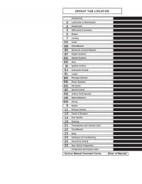
Подборка руководств на английском языке по техническому обслуживанию и ремонту автомобиля Jeep Grand Cherokee в кузове WJ 2000-2001 годов выпуска.
- Автор: —
- Издательство: Chrysler International
- Год издания: —
- Страниц: 2059
- Формат: PDF
- Размер: 187,8 Mb
Руководство на английском языке по техническому обслуживанию и ремонту автомобиля Jeep Grand Cherokee в кузове WK 2005 года выпуска.
- Автор: —
- Издательство: DaimlerChrysler Corporation
- Год издания: —
- Страниц: 7201
- Формат: PDF
- Размер: 81,3 Mb
Руководство по эксплуатации и техническому обслуживанию автомобиля Jeep Grand Cherokee 1999-2004 годов выпуска.
- Автор: —
- Издательство: Монолит
- Год издания: —
- Страниц: 150
- Формат: —
- Размер: —
Руководство по эксплуатации, техническому обслуживанию и ремонту автомобиля Jeep Grand Cherokee 1999-2004 годов выпуска с бензиновыми и дизельными двигателями.
- Автор: —
- Издательство: Автонавигатор
- Год издания: —
- Страниц: 528
- Формат: —
- Размер: —
Руководство по эксплуатации, техническому обслуживанию и ремонту автомобиля Jeep Grand Cherokee 2005-2009 годов выпуска с бензиновыми двигателями.
- Автор: —
- Издательство: Алфамер Паблишинг
- Год издания: —
- Страниц: 312
- Формат: —
- Размер: —

Руководство по техническому обслуживанию и ремонту автомобиля Jeep Grand Cherokee с 1993 года выпуска.
- Автор: —
- Издательство: —
- Год издания: —
- Страниц: 290
- Формат: PDF
- Размер: 124,0 Mb
Руководство по эксплуатации и ремонту автомобиля Jeep Grand Cherokee 1999-2004 годов выпуска с бензиновыми и дизельными двигателями.
- Автор: —
- Издательство: Монолит
- Год издания: —
- Страниц: 266
- Формат: —
- Размер: —
Руководство по эксплуатации и ремонту автомобиля Jeep Grand Cherokee с 2010 года выпуска с бензиновыми и дизельными двигателями.
- Автор: —
- Издательство: Монолит
- Год издания: —
- Страниц: 552
- Формат: —
- Размер: —

Руководство по эксплуатации и техническому обслуживанию автомобиля Jeep Grand Cherokee 2011 года выпуска.
- Автор: —
- Издательство: Chrysler International
- Год издания: 2010
- Страниц: 338
- Формат: PDF
- Размер: 5,5 Mb

Руководство по эксплуатации и техническому обслуживанию автомобиля Jeep Grand Cherokee 2014 года выпуска.
- Автор: —
- Издательство: Chrysler International
- Год издания: —
- Страниц: 372
- Формат: PDF
- Размер: 5,3 Mb
Руководство по эксплуатации, техническому обслуживанию и ремонту автомобиля Jeep Grand Cherokee.
- Автор: Б.У. Звонаревский
- Издательство: Арус
- Год издания: 2004
- Страниц: 279
- Формат: DjVu
- Размер: 16,8 Mb
Мультимедийное руководство по техническому обслуживанию и ремонту автомобиля Jeep Grand Cherokee 1993-1999 годов выпуска.
- Автор: —
- Издательство: —
- Год издания: —
- Страниц: —
- Формат: ISO
- Размер: 87,2 Mb

Посмотреть инструкция для Jeep Grand Cherokee (2018) бесплатно. Руководство относится к категории Автомобили, 9 человек(а) дали ему среднюю оценку 8.5. Руководство доступно на следующих языках: русский. У вас есть вопрос о Jeep Grand Cherokee (2018) или вам нужна помощь? Задайте свой вопрос здесь
Главная
| Jeep | |
| Grand Cherokee (2018) | |
| Автомобиль | |
| русский | |
| Руководство пользователя (PDF) |
Не можете найти ответ на свой вопрос в руководстве? Вы можете найти ответ на свой вопрос ниже, в разделе часто задаваемых вопросов о Jeep Grand Cherokee (2018).
Как перевести мили в километры?
Где я могу узнать идентификационный номер транспортного средства Jeep?
Что такое идентификационный номер транспортного средства (VIN)?
Когда транспортному средству Jeep требуется техническое обслуживание?
Когда следует заменять тормозную жидкость на Jeep?
В чем разница между топливом E10 и E5?
Одна или несколько дверей не открываются изнутри. Что мне делать?
Автомобильный радиоприемник не включается, что делать?
Инструкция Jeep Grand Cherokee (2018) доступно в русский?
Не нашли свой вопрос? Задайте свой вопрос здесь
- Manuals
- Brands
- Jeep Manuals
- Automobile
- 2022 CHEROKEE
- Owner’s manual
-
Contents
-
Table of Contents
-
Troubleshooting
-
Bookmarks
Quick Links
2022 GRAND CHEROKEE/GRAND CHEROKEE L
OWNE R ‘S MANUAL
Related Manuals for Jeep GRAND CHEROKEE 2022
Summary of Contents for Jeep GRAND CHEROKEE 2022
-
Page 1
2022 GRAND CHEROKEE/GRAND CHEROKEE L OWNE R ’S MANUAL… -
Page 2
This Owner’s Manual illustrates and describes the operation of features and equipment that are either standard or optional on this vehicle. This manual may also include a description of features and equipment that are no longer available or were not ordered on this vehicle. -
Page 3: Table Of Contents
TABLE OF CONTENTS INTRODUCTION ……………………..10 GETTING TO KNOW YOUR VEHICLE ………………18 GETTING TO KNOW YOUR INSTRUMENT PANEL …………94 STARTING AND OPERATING ………………..120 MULTIMEDIA ……………………..202 SAFETY ……………………….245 IN CASE OF EMERGENCY ………………..302 SERVICING AND MAINTENANCE ………………324 TECHNICAL SPECIFICATIONS ……………….. 385 CUSTOMER ASSISTANCE …………………
-
Page 4
INTRODUCTION SEATS …………..36 DOORS…………..28 Manual Door Locks ……….28 Manual Adjustment (Front Seats) — SYMBOLS KEY…………11 Power Door Locks ………..28 If Equipped …………37 ROLLOVER WARNING ………. 11 Keyless Enter ‘n Go™ — Passive Entry …29 Manual Adjustment (Rear Seats)….38 VEHICLE MODIFICATIONS/ALTERATIONS.. -
Page 5
Flash-To-Pass ………..60 INTERIOR STORAGE AND EQUIPMENT….75 UNIVERSAL GARAGE DOOR OPENER Automatic Headlights ……..60 (HOMELINK®) — IF EQUIPPED ……54 Storage ………….75 Parking Lights And Panel Lights……60 Sun Screens — If Equipped ……77 Before You Begin Programming Headlights On Automatically With Wipers ..60 USB/AUX Control ……….77 HomeLink®…………54 Headlight Illumination On Approach ….60… -
Page 6
GETTING TO KNOW YOUR STARTING AND OPERATING FOUR-WHEEL DRIVE OPERATION……132 Quadra-Trac I Operating Instructions/ INSTRUMENT PANEL STARTING THE ENGINE ……..120 Precautions — If Equipped……132 Automatic Transmission ……. 120 INSTRUMENT CLUSTER……… 94 Quadra-Trac II Operating Instructions/ Keyless Enter ‘n Go™ — Ignition….120 Instrument Cluster Descriptions …..95 Precautions —… -
Page 7
NIGHT VISION CAMERA SYSTEM — STOP/START SYSTEM — IF EQUIPPED …..141 PARKSENSE FRONT/REAR PARK ASSIST Autostop Mode ……….141 SYSTEM — IF EQUIPPED……..160 IF EQUIPPED …………178 Possible Reasons The Engine Does Not ParkSense Sensors……..161 Detection Range ……….. 180 Autostop………… -
Page 8
RECREATIONAL TOWING (BEHIND PASSENGER SCREEN — IF EQUIPPED ….. 225 First Time Starting Up (Using the Rear Screens)…………233 MOTORHOME) ………….195 Passenger Screen Permissions….226 Alexa Voice Control ……..234 Home Screen……….226 Towing This Vehicle Behind Another Listen Via Vehicle Speakers ……234 Audio And Video ………. -
Page 9
IN CASE OF EMERGENCY OFF-ROAD PAGES — IF EQUIPPED ….241 OCCUPANT RESTRAINT SYSTEMS ….265 Off-Road Pages Status Bar ……242 Occupant Restraint Systems Features ..265 HAZARD WARNING FLASHERS ……302 Vehicle Dynamics ……… 242 Important Safety Precautions …… 265 ASSIST AND SOS SYSTEM—… -
Page 10
SERVICING AND MAINTENANCE TECHNICAL SPECIFICATIONS TIRES…………..364 Tire Safety Information …….. 364 SCHEDULED SERVICING ……..324 VEHICLE IDENTIFICATION NUMBER (VIN) ..385 Tires — General Information ……372 Maintenance Plan ……… 324 BRAKE SYSTEM ………..385 Tire Types…………375 ENGINE COMPARTMENT ……..327 WHEEL AND TIRE TORQUE SPECIFICATIONS ..385 Spare Tires —… -
Page 11
CUSTOMER ASSISTANCE WARRANTY INFORMATION ……. 394 MOPAR® PARTS ……….394 SUGGESTIONS FOR OBTAINING SERVICE FOR REPORTING SAFETY DEFECTS ……394 YOUR VEHICLE …………392 In The 50 United States And Prepare For The Appointment …… 392 Washington, D.C……….394 Prepare A List ……….392 In Canada ………… -
Page 12: Introduction
Congratulations on the purchase of your new Jeep® vehicle. Be assured that it represents precision workmanship, distinctive styling, and high quality. The all-new Jeep® Grand Cherokee/Grand Cherokee L continues to build on its proud legacy as the most celebrated SUV ever, while raising the bar in luxury and performance.
-
Page 13: Symbols Key
SYMBOLS KEY ROLLOVER WARNING Utility vehicles have a significantly higher rollover rate than other types of These statements are against operating vehicles. This vehicle has a higher ground clearance and a higher center of WARNING! procedures that could result in a collision, bodily injury and/or death.
-
Page 14: Vehicle Modifications/Alterations
VEHICLE MODIFICATIONS/ALTERATIONS Red Warning Lights WARNING! Door Open Warning Light Ú page 109 Any modifications or alterations to this vehicle could seriously affect its roadworthiness and safety and may lead to a collision resulting in serious injury or death. Drowsy Driver Detected Warning Light Ú…
-
Page 15
Yellow Warning Lights Red Warning Lights Anti-Lock Brake System (ABS) Warning Light Night Vision Pedestrian Warning Light Ú page 112 Ú page 110 Drowsy Driver Detected System Fault Warning Light Oil Pressure Warning Light Ú page 112 Ú page 110 Electric Park Brake Warning Light Oil Temperature Warning Light Ú… -
Page 16
Yellow Warning Lights Yellow Warning Lights Low Washer Fluid Warning Light Tire Pressure Monitoring System (TPMS) Warning Light Ú page 113 Ú page 114 Night Vision Animal Warning Light Sway Bar Fault Warning Light Ú page 110 Ú page 115 Night Vision Pedestrian Warning Light Active Driving Assist — Driver Inattentiveness Warning Light Ú… -
Page 17
Yellow Indicator Lights Yellow Indicator Lights Forward Collision Warning (FCW) Or Pedestrian Emergency Air Suspension Active Indicator Light Braking (PEB) OFF Indicator Light Ú page 115 Ú page 115 Max Payload Exceeded Indicator Light NEUTRAL Indicator Light Ú page 115 Ú… -
Page 18
Green Indicator Lights Green Indicator Lights Front Fog Indicator Light Turn Signal Indicator Lights Ú page 116 Ú page 117 Active Lane Management Indicator Light Active Driving Assist — Driver Attentive Indicator Light Ú page 116 Ú page 116 Night Vision Active Indicator Light White Indicator Lights Ú… -
Page 19
Blue Indicator Lights White Indicator Lights High Beam Indicator Light Rear Seat Unoccupied Indicator Light Ú page 118 Ú page 117 Selec-Speed Control Indicator Light Gray Indicator Lights Ú page 117 Night Vision Suppressed Indicator Light Active Driving Assist On Indicator Light Ú… -
Page 20: Getting To Know Your Vehicle
GETTING TO KNOW YOUR VEHICLE KEYS If your vehicle is equipped with a Wireless 4 — Remote Start Charging Pad, the key fob may not be detected 5 — Power Liftgate if it is placed within 6 inches (15 cm) of the pad 6 —…
-
Page 21
GETTING TO KNOW YOUR VEHICLE To Lock/Unlock The Doors And Liftgate Key Left Vehicle Feature NOTE: This feature is enabled through Uconnect Push and release the unlock button on the key fob If a valid key fob is no longer detected inside the … -
Page 22
GETTING TO KNOW YOUR VEHICLE 1. Remove the emergency key (2) by pushing 3. Next, locate the gap on the right side of the key the emergency key release button (1) on the fob, which is positioned farther to the edge side of the key fob, and pulling the emergency than the left side gap. -
Page 23
GETTING TO KNOW YOUR VEHICLE NOTE: The key fob battery should only be replaced by qualified technicians. If the battery requires replacement, see an authorized dealer. WARNING! The integrated key fob contains a coin cell battery. Do not ingest the battery; there is a chemical burn hazard. -
Page 24: Sentry Key
GETTING TO KNOW YOUR VEHICLE Programming And Requesting Additional NOTE: that someone attempted to start the engine with an invalid key fob. In the event that a valid key fob Key Fobs When having the Sentry Key Immobilizer system is used to start the engine but there is an issue serviced, bring all vehicle keys with you to an Programming the key fob may be performed by an…
-
Page 25: Ignition Switch
GETTING TO KNOW YOUR VEHICLE IGNITION SWITCH The push button ignition can be placed in the following modes: ‘ ™ I EYLESS NTER GNITION The engine is stopped This feature allows the driver to operate the ignition switch with the push of a button as long as Some electrical devices (e.g.
-
Page 26: Remote Start — If Equipped
GETTING TO KNOW YOUR VEHICLE REMOTE START — IF EQUIPPED EMOTE TART WARNING! Push and release the Remote Start button on the This system uses the key fob to start the Do not leave children or animals inside parked key fob twice within five seconds.
-
Page 27: To Exit Remote Start Mode
GETTING TO KNOW YOUR VEHICLE For security, power window and power sunroof NOTE: WARNING! operation (if equipped) are disabled when the To avoid unintentional shutdowns, the system vehicle is in the Remote Start mode. Do not start or run an engine in a closed garage or …
-
Page 28: If Equipped
GETTING TO KNOW YOUR VEHICLE VEHICLE SECURITY SYSTEM — IF EQUIPPED — EMOTE TART OMFORT YSTEMS EMOTE TART INDSHIELD IPER — I QUIPPED CTIVATION QUIPPED The Vehicle Security system monitors the vehicle doors, hood, liftgate, and the Keyless Enter ‘n Go™ When Remote Start is activated, the front and rear When Remote Start is active and the outside Ignition for unauthorized operation.
-
Page 29: To Disarm The System
GETTING TO KNOW YOUR VEHICLE Push the lock button on the exterior Passive NOTE: If the Vehicle Security system is armed and the battery becomes disconnected, the Vehicle Entry door handle with a valid key fob avail- The driver’s door key cylinder cannot arm or …
-
Page 30: Doors
GETTING TO KNOW YOUR VEHICLE DOORS WARNING! Never leave children alone in a vehicle, or with ANUAL OCKS access to an unlocked vehicle. Allowing chil- The front doors can be manually unlocked with a dren to be in a vehicle unattended is dangerous single pull of the inside door handle.
-
Page 31: Keyless Enter ‘N Go™ — Passive Entry
GETTING TO KNOW YOUR VEHICLE Rear Passenger Power Door Locks Passive Entry unlock initiates illuminated approach (low beams, license plate lamp, parking lights, door Power door lock buttons are located on each rear handle pocket lights [if equipped]) for whichever door trim panel.
-
Page 32
GETTING TO KNOW YOUR VEHICLE To Unlock From The Driver Or Passenger Side Frequency Operated Button Integrated Key vehicle. The vehicle will not unlock the doors when (FOBIK-Safe) any of the following conditions are true: With a valid Passive Entry key fob within 5 ft (1.5 m) The doors are manually locked using the emer- of the door handle, grab the handle to unlock the To minimize the possibility of unintentionally… -
Page 33: Automatic Unlock Doors On Exit
GETTING TO KNOW YOUR VEHICLE NOTE: To Unlock/Enter The Liftgate NOTE: Do NOT grab the door handle when touching the The liftgate Passive Entry lock button will lock all The liftgate Passive Entry unlock feature is built lock icon. This could unlock the door(s). doors and the liftgate Ú…
-
Page 34: Child-Protection Door Lock System — Rear Doors
GETTING TO KNOW YOUR VEHICLE STEERING WHEEL NOTE: HILD ROTECTION — R When the Child-Protection Door Lock system is YSTEM OORS engaged, the door can be opened only by using ANUAL ELESCOPING TEERING To provide a safer environment for small children the outside door handle even though the inside —…
-
Page 35: Power Tilt/Telescoping Steering Column — If Equipped
GETTING TO KNOW YOUR VEHICLE Use the four-way control to adjust the steering The heated steering wheel button is located on the WARNING! column. center of the instrument panel below the radio screen, and within the Comfort screen of the Do not adjust the steering column while driving.
-
Page 36: Uconnect Voice Recognition Quick Tips — If Equipped
Wake Up Phone Call, And Send Or Receive A Text word, “Hey Uconnect” or “Hey Jeep®”. The factory the VR button or say the “Wake Up” word, 1 — For Vehicles Not Equipped With Navigation: wait until after the beep, then say your Voice default Wake Up word is set to “Hey Uconnect”…
-
Page 37: Additional Information
GETTING TO KNOW YOUR VEHICLE Passenger’s Side (If Equipped) DDITIONAL NFORMATION ROGRAMMING EMORY EATURE Seat Position © 2022 FCA US LLC. All rights reserved. Mopar and To create a new memory profile, perform the The memory settings switches are located on the Uconnect are registered trademarks and Mopar following: front door panels, next to the door handle, and…
-
Page 38: Linking And Unlinking The Key Fob
GETTING TO KNOW YOUR VEHICLE SEATS NOTE: INKING NLINKING Your key fobs can be unlinked from your driver’s EMORY Seats are a part of the Occupant Restraint system side memory settings by pushing the set (S) button, of the vehicle. and within 10 seconds, pushing the unlock button Your key fobs can be programmed to recall one of on the key fob.
-
Page 39: Manual Adjustment (Front Seats)
GETTING TO KNOW YOUR VEHICLE ) — Manual Front Passenger Seatback ANUAL DJUSTMENT RONT EATS Adjustment — Recline QUIPPED To recline, lean forward slightly and lift the lever located on the outboard side of the seat. WARNING! Then, push the seat rearward to the desired position Adjusting a seat while the vehicle is moving is …
-
Page 40: Manual Adjustment (Rear Seats)
GETTING TO KNOW YOUR VEHICLE Second Row Bench Seat — If Equipped SECOND ROW BENCH SEAT RECLINE ANUAL DJUSTMENT EATS ADJUSTMENT Vehicles equipped with third row seating may have SECOND ROW BENCH SEAT FORWARD/ To recline, lean forward slightly and lift the lever located a second row bench seat, or second row captain’s REARWARD ADJUSTMENT on the outboard side of the seat.
-
Page 41
GETTING TO KNOW YOUR VEHICLE SECOND ROW BENCH SEAT EASY ACCESS FOR WARNING! THIRD ROW — IF EQUIPPED Do not ride with the seatback reclined so that If the vehicle is equipped with third row seating, the shoulder belt is no longer resting against the second row seats can tip forward to allow your chest. -
Page 42
GETTING TO KNOW YOUR VEHICLE Access To Third Row Seats Rear Seat Adjustment Bar Rear Seat Recline Lever To return the seat to a sitting position, unfold the SECOND ROW CAPTAIN’S CHAIRS RECLINE WARNING! seatback upright until it locks and push the seat ADJUSTMENT rearward until the track locks. -
Page 43
GETTING TO KNOW YOUR VEHICLE SECOND ROW CAPTAIN’S CHAIRS FOLD FLAT WARNING! SEATS Be certain that the seatback is securely locked The second row seatbacks can be folded flat to into position. If the seatback is not securely carry cargo. locked into position the seat will not provide Pull upward on the recline lever located on the the proper stability for child seats and/or… -
Page 44: Power Adjustment (Front Seats)
GETTING TO KNOW YOUR VEHICLE NOTE: To raise the seat, pull the seat toward you using the strap located on the back of the seat. The second row seats must be in their full upright position or folded flat when folding the third row WARNING! seats.
-
Page 45
GETTING TO KNOW YOUR VEHICLE Adjusting The Seat Up Or Down Push the top of the button to extend the bolsters, WARNING! or push the bottom of the button to retract the The height of the seats can be adjusted up or bolsters. -
Page 46: Power Adjustment (Rear Seats)
GETTING TO KNOW YOUR VEHICLE ) — Power Lumbar — If Equipped The distance the driver seat moves depends on OWER DJUSTMENT EATS where you have the driver seat positioned when Vehicles equipped with power driver or passenger QUIPPED you place the vehicle’s ignition in the OFF position. seats may also be equipped with power lumbar.
-
Page 47: Power Seatback Massage
GETTING TO KNOW YOUR VEHICLE The head restraints will lower automatically as There are also power folding switches for the third CAUTION! necessary when the power seat begins to move row seats located on the C-pillar (just behind the when the vehicle is in PARK, and a rear door or rear doors on the trim panels).
-
Page 48: Heated Seats — If Equipped
GETTING TO KNOW YOUR VEHICLE Front Heated Seats Low Extend Rock Climb The front heated seats control buttons are located on the center stack below the The selected settings will save in the system’s radio screen or within the Uconnect memory when turned off, and will resume the next system.
-
Page 49: Ventilated Seats — If Equipped
GETTING TO KNOW YOUR VEHICLE — I Rear Heated Seats — If Equipped Rear Ventilated Seats — If Equipped ENTILATED EATS QUIPPED The two second row outboard seats The two second row outboard seats may Located in the seat cushion and seatback are fans may be equipped with heated seats.
-
Page 50: Head Restraints
GETTING TO KNOW YOUR VEHICLE NOTE: ESTRAINTS The head restraints should only be removed by Head restraints are designed to reduce the risk of qualified technicians, for service purposes only. injury by restricting head movement in the event of If either of the head restraints require removal, a rear impact.
-
Page 51
GETTING TO KNOW YOUR VEHICLE The center head restraint has one adjustment WARNING! WARNING! position, and can be adjusted up or down when the seat is occupied. Pull up on the head restraint to All occupants, including the driver, should not All occupants, including the driver, should not … -
Page 52: Mirrors
GETTING TO KNOW YOUR VEHICLE MIRRORS NOTE: The head restraints will also automatically fold when the seatbacks are folded forward using the For information on child restraint tethering, see release handles on the backs of the seats from the Ú page 265. NSIDE EARVIEW IRROR…
-
Page 53
GETTING TO KNOW YOUR VEHICLE Automatic Dimming Mirror — If Equipped Position the mirror in the regular Automatic Use the left and right buttons to scroll through Dimming Mirror mode, then activate the Digital menu options. The mirror head can be adjusted up, down, left, Rearview Mirror mode. -
Page 54: Illuminated Vanity Mirrors
GETTING TO KNOW YOUR VEHICLE Outside Mirrors Folding Feature 3. Pivot the sun visor toward the side window. LLUMINATED ANITY IRRORS 4. Extend the sun visor blade for additional sun All outside mirrors are hinged and may be moved To access an illuminated vanity mirror, flip down blockage.
-
Page 55: Automatic Power Folding
GETTING TO KNOW YOUR VEHICLE Power Folding — If Equipped UTOMATIC OWER OLDING To fold the door mirrors in using the Power Folding — I IRRORS QUIPPED Mirror function, rotate the control switch to the When enabled within Uconnect Settings power folding position.
-
Page 56: Heated Mirrors — If Equipped
GETTING TO KNOW YOUR VEHICLE UNIVERSAL GARAGE DOOR OPENER NOTE: To operate HomeLink®, push and release any of the programmed HomeLink® buttons. If the mirrors were folded manually, by using the (HOMELINK®) — IF EQUIPPED These buttons will activate the devices they are power folding mirror switch on the driver’s door programmed to with each press of the corre- panel, they will not automatically unfold.
-
Page 57: Erasing All The Home Link Channels
GETTING TO KNOW YOUR VEHICLE ® antenna is attached to the device. The button may 3. Push and hold the HomeLink® button you RASING not be immediately visible when looking at the want to program while you push and hold the HANNELS device.
-
Page 58: Miscellaneous Device
GETTING TO KNOW YOUR VEHICLE Return to the vehicle and push the programmed EPROGRAMMING INGLE WARNING! HomeLink® button three times (holding the button ® B UTTON for two seconds each time). If the garage door Do not run your vehicle in a closed garage or …
-
Page 59: Security
GETTING TO KNOW YOUR VEHICLE during programming. Similar to this Canadian law, 5. Push and hold the programmed HomeLink® ECURITY button and observe the indicator light. some U.S. gate operators are designed to time-out It is advised to erase all channels before you sell or in the same manner.
-
Page 60: Exterior Lights
GETTING TO KNOW YOUR VEHICLE EXTERIOR LIGHTS WARNING! Vehicle exhaust contains carbon monoxide, a EADLIGHT WITCH dangerous gas. Do not run your vehicle in the The headlight switch is located on the left side of garage while programming the transceiver. the instrument panel, next to the steering wheel.
-
Page 61: Multifunction Lever
GETTING TO KNOW YOUR VEHICLE To turn on the headlights, rotate the headlight If allowed by law in the country in which the ULTIFUNCTION EVER switch clockwise. When the headlight switch is on, vehicle was purchased the Daytime Running The multifunction lever is located on the left side of the parking lights, taillights, license plate light and Lights can be turned on and off using the…
-
Page 62: Flash-To-Pass
GETTING TO KNOW YOUR VEHICLE NOTE: Running Lights (DRLs) will be activated along with UTOMATIC EADLIGHTS the front and rear marker lights. The DRLs may be The Automatic High Beam Headlight system can This system automatically turns the headlights on or off deactivated when the parking brake is engaged.
-
Page 63: Headlight Delay
GETTING TO KNOW YOUR VEHICLE Proximity Wake-Up — If Equipped Headlight Animation — If Equipped NOTE: The headlight delay time is programmable through This feature is enabled/disabled within the When “Headlight Illumination On Approach” is Uconnect Settings Ú page 203. Uconnect system, and is activated when the turned on, and set to a time value above zero, the operator approaches the driver’s door, passenger’s…
-
Page 64: Turn Signals
GETTING TO KNOW YOUR VEHICLE IGNALS ATTERY AVER Move the multifunction lever up or down and the To protect the life of your vehicle’s battery, load arrows on each side of the instrument cluster will shedding is provided for both the interior and flash to show proper operation of the front and rear exterior lights.
-
Page 65: Interior Lights
GETTING TO KNOW YOUR VEHICLE INTERIOR LIGHTS Dimmer Controls The dimmer controls are inboard and adjacent to OURTESY IGHTS the headlight switch located on the left side of the instrument panel. Courtesy and dome lights are turned on when the With the parking lights or headlights on, rotating front doors are opened or the Dome ON button is the right dimmer control upward will increase…
-
Page 66: Windshield Wipers And Washers
GETTING TO KNOW YOUR VEHICLE WINDSHIELD WIPERS AND WASHERS Multicolor Ambient Lighting — If Equipped The color of certain ambient lighting inside of the The windshield wiper/washer lever is located on vehicle can be selected within the Apps menu on the right side of the steering column.
-
Page 67: Windshield Wiper Operation
GETTING TO KNOW YOUR VEHICLE regulate the wipe interval from a minimum of one Due to washer pump packaging, the front INDSHIELD IPER PERATION cycle every second to a maximum of approximately camera washers will run out of fluid before the The wipers and washers are operated by a switch 36 seconds between cycles.
-
Page 68: Rain Sensing Wipers — If Equipped
GETTING TO KNOW YOUR VEHICLE — I The Rain Sensing system has protective features ENSING IPERS QUIPPED IPER ASHER for the wiper blades and arms. It will not operate This feature senses rain or snowfall on the The rear wiper/washer is operated by rotating a under the following conditions: windshield and automatically activates the wipers.
-
Page 69: Windshield Wiper De-Icer
GETTING TO KNOW YOUR VEHICLE CLIMATE CONTROLS — INDSHIELD IPER QUIPPED The Climate Control system allows you to regulate the temperature, air flow, and direction of air Your vehicle may be equipped with a Windshield circulating throughout the vehicle. The controls are Wiper De-Icer feature that may be activated under located on the touchscreen and on the instrument the following conditions:…
-
Page 70
GETTING TO KNOW YOUR VEHICLE A/C Button AUTO Button MAX Defrost automatically turns off after 20 minutes. Press and release the button on the The AUTO button automatically controls the Rear Defrost Button touchscreen or push and release the interior cabin temperature by adjusting button on the faceplate to change the distribution and amount of airflow. -
Page 71
GETTING TO KNOW YOUR VEHICLE Rear Climate Control Button — If Equipped with the driver temperature, mode, and blower Panel Mode settings. Changing the front passenger temperature Press and release this button on the Air comes from the outlets in the or rear passenger temperature, mode, and blower climate control touchscreen to access instrument panel. -
Page 72
GETTING TO KNOW YOUR VEHICLE Mix Mode Controlling The Rear Climate Controls The Three-Zone and Four-Zone ATC system allows for adjustment of the rear climate controls from From The Front ATC Panel — If Equipped Air is directed through the floor, defrost, and the front ATC panel. -
Page 73
GETTING TO KNOW YOUR VEHICLE REAR LOCK BUTTON REAR BLOWER CONTROL Rear Automatic Temperature Control — If Equipped Press and release this button to lock out Rear Blower Control is used to regulate the rear manual temperature controls the amount of air forced through the rear from adjusting the rear temperature climate system. -
Page 74
GETTING TO KNOW YOUR VEHICLE AUTO BUTTON REAR MODE CONTROL REAR TEMPERATURE LOCK The AUTO button automatically controls Push the rear mode button to adjust The Rear Temperature Lock symbol on the the interior cabin temperature by airflow distribution. The rear mode rear display is illuminated when the rear adjusting distribution and amount of settings are shown in the rear display. -
Page 75: Automatic Temperature Control (Atc)
GETTING TO KNOW YOUR VEHICLE Once the desired temperature is shown on the rear NOTE: Push the VR button. After the beep, say one of the display, the ATC System will automatically achieve It is not necessary to move the temperature following commands: and maintain that comfort level.
-
Page 76
GETTING TO KNOW YOUR VEHICLE Summer Operation Outside Air Intake Windshield Wiper De-Icer — If Equipped The engine cooling system must be protected with a Make sure the air intake, located directly in front of The Windshield Wiper De-Icer is a heating element high-quality antifreeze coolant to provide proper the windshield, is free of obstructions, such as located at the base of the windshield. -
Page 77: Interior Storage And Equipment
GETTING TO KNOW YOUR VEHICLE INTERIOR STORAGE AND EQUIPMENT Operating Tips Chart Front Center Console The front center console contains both an upper WEATHER CONTROL SETTINGS TORAGE and a lower storage area. Set the mode control to To open the upper storage compartment, pull the Glove Compartment (Panel Mode), (MAX A/C)
-
Page 78
GETTING TO KNOW YOUR VEHICLE Sunglasses Bin Door Rear Full Center Console — If Equipped At the front of the console a compartment is The rear full center console contains both an upper provided for the storage of a pair of sunglasses. and a lower storage area. -
Page 79: Sun Screens — If Equipped
GETTING TO KNOW YOUR VEHICLE — I USB/AUX C “Another device is in use through the same USB CREENS QUIPPED ONTROL port. Please disconnect the first device to use Sun screens are available for the second row This feature allows an external USB device to be the second device”.
-
Page 80
GETTING TO KNOW YOUR VEHICLE Once a device is connected to the USB port, it will By using an auxiliary cable to connect an external If equipped with a third row, a set of two USB ports begin charging and is ready for use with the device: can be used to charge a device. -
Page 81: Electrical Power Outlets
GETTING TO KNOW YOUR VEHICLE NOTE: LECTRICAL OWER UTLETS The rear cargo power outlet can be changed from Your vehicle is equipped with 12 Volt (13 Amp) battery powered to powered by ignition in the power outlets that can be used to power cellular ON/RUN position by switching the cargo area phones, small electronics and other low powered power outlet fuse from F44B to F44A in the rear…
-
Page 82: Power Inverter — If Equipped
GETTING TO KNOW YOUR VEHICLE — IRELESS HARGING CAUTION! QUIPPED Accessories that draw higher power (i.e., coolers, vacuum cleaners, lights, etc.) will degrade the battery even more quickly. Only use these intermit- tently and with greater caution. After the use of high power draw accessories, …
-
Page 83: Windows
GETTING TO KNOW YOUR VEHICLE WINDOWS The wireless charging pad is equipped with an The power windows may be operated from anti-slip mat to hold your mobile phone in place, outside of the vehicle by using the key fob. and an LED indicator light.
-
Page 84: Wind Buffeting
GETTING TO KNOW YOUR VEHICLE Reset Auto-Up Auto-Up Feature With Anti-Pinch Protection For windows equipped with the AUTO feature, lift Should the Auto-Up feature stop working, the the window switch up to the second detent, and window may need to be reset. To reset Auto-Up: release;…
-
Page 85: Power Sunroof
GETTING TO KNOW YOUR VEHICLE POWER SUNROOF Opening And Closing The Sunroof WARNING! Express Open/Close — Never leave children unattended in a vehicle, INGLE OWER UNROOF Push the switch rearward and release it within or with access to an unlocked vehicle. Never QUIPPED one-half second and the sunroof will open leave the key fob in or near the vehicle, or in a…
-
Page 86: Dual Pane Power Sunroof
GETTING TO KNOW YOUR VEHICLE Ignition Off Operation Venting The Sunroof Push and release the Vent button within The power sunroof switch will remain active for up one half second and the sunroof will open to the to approximately 10 minutes after the ignition vent position.
-
Page 87
GETTING TO KNOW YOUR VEHICLE During Express Open or Express Close operation, NOTE: WARNING! any other movement of the sunroof switch will stop If the sunshade is closed, it will automatically open the sunroof. to half open position prior to the roof opening to In a collision, there is a greater risk of being … -
Page 88: Hood
GETTING TO KNOW YOUR VEHICLE During Express Open or Express Close operation, switch is placed in the OFF position. Opening either 2. Reach under the hood from outside the any other actuation of the sunroof switches will front door will cancel this feature. vehicle, move the safety latch to the left and stop the sunshade in a partially open position.
-
Page 89: Liftgate
GETTING TO KNOW YOUR VEHICLE LIFTGATE NOTE: LOSE IFTGATE When you push the electronic liftgate release button, There are several different ways to close the liftgate: either only the liftgate will unlock, or all the doors and NLOCK IFTGATE the liftgate will unlock, depending on the selected Manually (grab the liftgate closing handle and …
-
Page 90: Adjustable Power Liftgate Height
GETTING TO KNOW YOUR VEHICLE — I Power Liftgate Malfunction Procedure: DJUSTABLE OWER IFTGATE EIGHT ANDS IFTGATE QUIPPED 1. In the event of a power malfunction to the The maximum height that the liftgate will open can liftgate, the liftgate can be released by be adjusted and saved so that the liftgate will only accessing the service release feature in open to the desired height.
-
Page 91: Cargo Area Features
GETTING TO KNOW YOUR VEHICLE When a valid kicking motion is completed, the liftgate There are pinch sensors attached to the side of Gas props support the liftgate in the open position. will chime, the hazard lights will flash and the liftgate the liftgate opening.
-
Page 92
GETTING TO KNOW YOUR VEHICLE Additional storage can be found under the storage WARNING! lid. To access the lower storage, lift the handle and raise the storage lid. Cargo tie-downs are not safe anchors for a child seat tether strap. In a sudden stop or accident, a tie-down could pull loose and allow the child seat to come loose. -
Page 93
GETTING TO KNOW YOUR VEHICLE Foldable Cargo Area Cover — If Equipped WARNING! The purpose of this cover is for privacy, not to Place as much cargo as possible in front of the secure loads. It will not prevent cargo from shifting rear axle. -
Page 94
GETTING TO KNOW YOUR VEHICLE To cover the cargo area: 1. Remove the folded cover from the storage pouch, and unfold using a twisting motion. 2. Insert the pins on the ends of the cover into the slots on each side of the pillar trim. Step 3 Folding The Cargo Cover 1 —… -
Page 95: Roof Luggage Rack — If Equipped
GETTING TO KNOW YOUR VEHICLE ROOF LUGGAGE RACK — IF EQUIPPED NOTE: CAUTION! If any cargo (or any metallic object) is placed over The crossbars and siderails are designed to carry the satellite radio antenna (if equipped), you may To avoid damage to the roof rack and vehicle, …
-
Page 96: Getting To Know Your Instrument Panel
GETTING TO KNOW YOUR INSTRUMENT PANEL INSTRUMENT CLUSTER Holding the OK button on the Instrument Cluster Display controls located on the steering wheel will allow you to change your display from Digital to Analog.
-
Page 97: Instrument Cluster Descriptions
GETTING TO KNOW YOUR INSTRUMENT PANEL Use this QR code to access your 3. Tachometer WARNING! digital experience. Indicates the engine speed in revolutions A hot engine cooling system is dangerous. You or per minute (RPM x 1000). others could be badly burned by steam or boiling 4.
-
Page 98: Instrument Cluster
GETTING TO KNOW YOUR INSTRUMENT PANEL INSTRUMENT CLUSTER Holding the OK button on the Instrument Cluster Display controls located on the steering wheel will allow you to change your display from Analog to Digital.
-
Page 99: Instrument Cluster Descriptions
GETTING TO KNOW YOUR INSTRUMENT PANEL NOTE: NSTRUMENT LUSTER ESCRIPTIONS WARNING! The Instrument Cluster Warning Indicators will illu- 1. Tachometer A hot engine cooling system is dangerous. You or minate briefly for a bulb check when the ignition is first cycled. Indicates the engine speed in revolutions others could be badly burned by steam or boiling …
-
Page 100: Location And Controls
GETTING TO KNOW YOUR INSTRUMENT PANEL The system allows the driver to select information 2. OK Button OCATION ONTROLS by pushing the following buttons mounted on the Push the OK button to access/select the infor- steering wheel: mation screens or submenu screens of a main menu item.
-
Page 101: Engine Oil Life Reset
GETTING TO KNOW YOUR INSTRUMENT PANEL Display Options Navigate Left or Right to highlight desired tile Navigation Holding OK will also allow you to change your Press OK to select the tile and navigate to the Route Set / Route Not Set …
-
Page 102: Display And Messages
GETTING TO KNOW YOUR INSTRUMENT PANEL NOTE: Unless reset, this message will continue to display each Submenu Dots — Whenever there are time the ignition is placed in the ON/RUN position. To submenus available, the position within the If the indicator message illuminates when you start turn off the message temporarily, push and release the submenus is shown here the vehicle, the oil change indicator system did not…
-
Page 103
GETTING TO KNOW YOUR INSTRUMENT PANEL Unstored Messages Unstored Messages Until RUN Five Second Unstored Messages This message type is displayed indefinitely or These messages deal primarily with the Remote When the appropriate conditions occur, this until the condition that activated the message is Start feature. -
Page 104: Instrument Cluster Display Menu Items
GETTING TO KNOW YOUR INSTRUMENT PANEL The Reconfigurable Telltales section is divided into Main Menu Stored Messages the white or yellow telltales area on the left, and Speedometer Messages the green or red telltales area on the right. Driver Assist —…
-
Page 105
GETTING TO KNOW YOUR INSTRUMENT PANEL Driver Assist — If Equipped Gauge Summary Stop/Start Status — If Equipped While viewing the Speedometer menu title, push and Coolant Temperature — If Equipped Display current status of Stop/Start system. release the left or right arrow button until the Displays the current temperature of the coolant. -
Page 106
GETTING TO KNOW YOUR INSTRUMENT PANEL OFF ROAD STORED MESSAGES Upper Left Push and release the up or down arrow Push and release the up or down arrow Fuel Economy button until the Off Road Menu title is highlighted. button until the Messages Menu item is None Time Current… -
Page 107: Head Up Display (Hud)
GETTING TO KNOW YOUR INSTRUMENT PANEL (HUD) — Odometer ON/OFF ISPLAY Show QUIPPED Hide Use this QR code to access your digital experience. Favorite Menus NOTE: Trip Off Road Main Menu The HUD feature Settings are (Show/Hide) (Show/Hide) available at any vehicle speed.
-
Page 108: Battery Saver On/Battery Saver Mode Message — Electrical Load Reduction Actions — If Equipped
GETTING TO KNOW YOUR INSTRUMENT PANEL Content and Layout Advanced: Speed, Speed Limit, Navigation, Display Height Driver Assist (ACC/Cruise, Active Lane Simple: Speed, Speed Limit Brightness Management, Active Driving Assist), Gear Standard: Speed, Speed Limit, Navigation NOTE: …
-
Page 109
GETTING TO KNOW YOUR INSTRUMENT PANEL Load reduction is only active when the engine is Loss of the battery charge may indicate one or What to do when an electrical load reduction running. It will display a message if there is a risk more of the following conditions: action message is present (“Battery Saver On”… -
Page 110: Warning Lights And Messages
GETTING TO KNOW YOUR INSTRUMENT PANEL WARNING LIGHTS AND MESSAGES Air Bag Warning Light been corrected. If the problem is related to the brake booster, the ABS pump will run when This warning light will illuminate to The warning/indicator lights will illuminate in the applying the brake, and a brake pedal pulsation indicate a fault with the air bag, and will instrument panel together with a dedicated…
-
Page 111
GETTING TO KNOW YOUR INSTRUMENT PANEL Vehicles equipped with the Anti-Lock Brake System This indicates a possible problem with the Electric Power Steering (EPS) Fault (ABS) are also equipped with Electronic Brake electrical system or a related component. Warning Light Force Distribution (EBD). -
Page 112
GETTING TO KNOW YOUR INSTRUMENT PANEL NOTE: Hood Open Warning Light Night Vision Pedestrian Warning Light This light may turn on if the accelerator and brake This warning light will illuminate when the The Night Vision Pedestrian Warning pedals are pressed at the same time. hood is left open and not fully closed. -
Page 113: Yellow Warning Lights
GETTING TO KNOW YOUR INSTRUMENT PANEL Rear Seat Belt Reminder Indicator Light — Transmission Temperature Warning Vehicle Security Warning Light — If Equipped Light — If Equipped If Equipped This light indicates when a rear seat belt is This warning light will illuminate to warn This light will flash at a fast rate for unbuckled in the second row.
-
Page 114
GETTING TO KNOW YOUR INSTRUMENT PANEL Anti-Lock Brake System (ABS) Warning Electronic Stability Control (ESC) Active Electronic Stability Control (ESC) OFF Light Warning Light — If Equipped Warning Light — If Equipped This warning light monitors the ABS. This warning light will indicate when the This warning light indicates the ESC is off. -
Page 115
GETTING TO KNOW YOUR INSTRUMENT PANEL Low Washer Fluid Warning Light — after engine start. The vehicle should be serviced if Service 4WD Warning Light — If Equipped the light stays on through several typical driving If Equipped This warning light will illuminate to signal styles. -
Page 116
GETTING TO KNOW YOUR INSTRUMENT PANEL Tire Pressure Monitoring System (TPMS) variety of reasons, including the installation of As an added safety feature, your vehicle has been equipped with a TPMS that illuminates a low tire replacement or alternate tires or wheels on the Warning Light pressure telltale when one or more of your tires is vehicle that prevent the TPMS from functioning… -
Page 117: Yellow Indicator Lights
GETTING TO KNOW YOUR INSTRUMENT PANEL Sway Bar Fault Warning Light Air Suspension Off-Road 1 Indicator Max Payload Exceeded Indicator Light Light — If Equipped This light will illuminate when there is a This light indicates that the maximum fault in the sway bar disconnect system payload may have been exceeded or load This light will illuminate when the Ú…
-
Page 118: Green Indicator Lights
GETTING TO KNOW YOUR INSTRUMENT PANEL Cruise Control SET Indicator Light — Parking/Headlights On Indicator Light REEN NDICATOR IGHTS If Equipped This indicator light will illuminate when Active Driving Assist — Driver Attentive the parking lights or headlights are This indicator light will illuminate when Indicator Light turned on Ú…
-
Page 119: White Indicator Lights
GETTING TO KNOW YOUR INSTRUMENT PANEL Turn Signal Indicator Lights Adaptive Cruise Control (ACC) Ready Rear Seat Unoccupied Indicator Indicator Light — If Equipped Light — If Equipped When the left or right turn signal is activated, the turn signal indicator will flash This light will turn on when ACC has been This light indicates when the rear independently and the corresponding…
-
Page 120: Blue Indicator Lights
GETTING TO KNOW YOUR INSTRUMENT PANEL ONBOARD DIAGNOSTIC SYSTEM — OBD II NDICATOR IGHTS NBOARD IAGNOSTIC YSTEM (OBD II) C YBERSECURITY High Beam Indicator Light Your vehicle is equipped with a sophisticated Onboard Diagnostic system called OBD II. This system monitors This indicator light will illuminate to indicate Your vehicle is required to have OBD II and a the performance of the emissions, engine, and…
-
Page 121: Emissions Inspection And Maintenance
GETTING TO KNOW YOUR INSTRUMENT PANEL EMISSIONS INSPECTION AND Your vehicle has a simple ignition actuated test, The MIL will not flash at all and will remain which you can use prior to going to the test station. fully illuminated until you place the ignition MAINTENANCE PROGRAMS To check if your vehicle’s OBD II system is ready, in the off position or start the engine.
-
Page 122: Starting And Operating
STARTING AND OPERATING STARTING THE ENGINE WARNING! CAUTION! Before starting your vehicle, adjust your seat, Do not leave the key fob in or near the vehicle, Shift into PARK only after the vehicle has adjust the inside and outside mirrors, fasten or in a location accessible to children, and do come to a complete stop.
-
Page 123: Autopark
STARTING AND OPERATING 3. The system takes over and attempts to start NOTE: the vehicle. If the vehicle fails to start, the If the gear selector is not in PARK, and the ENGINE AutoPark is a supplemental feature to assist in starter will disengage automatically after START/STOP button is pushed once with the vehicle placing the vehicle in PARK (P) should the…
-
Page 124: If Engine Fails To Start
STARTING AND OPERATING NOTE: If the vehicle is not in PARK and the driver turns off Additional customer warnings will be given when the engine, the vehicle may AutoPark. both of these conditions are met: In some cases the ParkSense graphic will be displayed in the instrument cluster.
-
Page 125: Cold Weather Operation
STARTING AND OPERATING ENGINE BREAK-IN RECOMMENDATIONS EATHER PERATION WARNING! –22°F O −30°C) ELOW A long break-in period is not required for the engine Never pour fuel or other flammable liquid into and drivetrain (transmission and axle) in your the throttle body air inlet opening in an To ensure reliable starting at these temperatures, vehicle.
-
Page 126: Parking Brake
STARTING AND OPERATING PARKING BRAKE If the Auto Park Brake feature is enabled, the parking brake will automatically engage whenever the transmission is placed into PARK. If your foot is (EPB) LECTRIC RAKE on the brake pedal, you may notice a small amount Your vehicle is equipped with an EPB that offers of brake pedal movement while the parking brake simple operation, and some additional features…
-
Page 127: Auto Park Brake
STARTING AND OPERATING WARNING! WARNING! WARNING! Never use the PARK position as a substitute for Driving the vehicle with the parking brake Always fully apply the parking brake when leaving the parking brake. Always apply the parking brake your vehicle, or it may roll and cause damage or engaged, or repeated use of the parking brake fully when parked to guard against vehicle move-…
-
Page 128: Safehold
STARTING AND OPERATING stop until the driver applies the accelerator pedal. RAKE AINTENANCE Hold ‘N Go can be activated or deactivated by SafeHold is a safety feature of the EPB system that We recommend having your brakes serviced by an pushing the HOLD button located on the switch will place the transmission in PARK, and engage authorized dealer.
-
Page 129: Automatic Transmission
STARTING AND OPERATING When brake maintenance work is complete, the WARNING! WARNING! following steps must be followed to reset the parking brake system to normal operation: Your vehicle could move and injure you and Unintended movement of a vehicle could …
-
Page 130: Ignition Park Interlock
STARTING AND OPERATING NOTE: RAKE RANSMISSION HIFT CAUTION! In the event of a mismatch between the gear (BTSI) S NTERLOCK YSTEM selector position and the actual transmission gear Damage to the transmission may occur if the (for example, driver selects PARK while driving), following precautions are not observed: This vehicle is equipped with a BTSI system that the position indicator will blink continuously until…
-
Page 131
STARTING AND OPERATING The transmission gear selector has only PARK, Gear Ranges NOTE: REVERSE, NEUTRAL, and DRIVE positions. Manual On four-wheel drive vehicles be sure that the Do not press the accelerator pedal when shifting downshifts can be made using the steering wheel transfer case is in a drive position. -
Page 132
STARTING AND OPERATING REVERSE (R) DRIVE (D) Transmission Limp Home Mode This range is for moving the vehicle backward. This range should be used for most city and Transmission function is monitored electronically for Shift into REVERSE only after the vehicle has come highway driving. -
Page 133
STARTING AND OPERATING 3. Push and hold the ignition switch until the NOTE: engine turns off. The paddle shifters (if equipped) may be disabled (or re-enabled, as desired) using the Uconnect 4. Wait approximately 30 seconds. Programmable Settings. 5. Restart the engine. In AutoStick mode, the transmission will shift up or Shift into the desired gear range. -
Page 134: Sport Mode — If Equipped
STARTING AND OPERATING SPORT MODE — IF EQUIPPED FOUR-WHEEL DRIVE OPERATION The system will ignore attempts to upshift at too low of a vehicle speed. The driveline is equipped with a Front Axle Disconnect Holding the (-) paddle pressed, will downshift …
-
Page 135: Quadra-Trac Ii Operating Instructions/Precautions — If Equipped
STARTING AND OPERATING NOTE: Proper operation of four-wheel drive vehicles depends N (NEUTRAL) on tires of equal size, type, and circumference on each The Quadra-Trac I system is not appropriate for This range disengages the driveline from the wheel. Any difference will adversely affect performance conditions where 4WD LOW range is recom- powertrain.
-
Page 136: Shifting Procedures
STARTING AND OPERATING 4WD LOW To 4WD HI occur. The preferred method is with the vehicle HIFTING ROCEDURES rolling 0 to 3 mph (0 to 5 km/h). If the vehicle is With the vehicle at speeds of 0 to 3 mph (0 to 4WD HI To 4WD LOW moving faster than 3 mph (5 km/h), the transfer 5 km/h), the ignition switch in the ON position or…
-
Page 137: Electronic Sway Bar Disconnect
STARTING AND OPERATING — NOTE: LECTRONIC ISCONNECT WARNING! The stabilizer/sway bar may be torque locked due QUIPPED Ensure the stabilizer/sway bar is reconnected to left and right suspension height differences. This condition is due to driving surface differences Your vehicle may be equipped with an electronic before driving on hard surfaced roads or at or vehicle loading.
-
Page 138: Selec-Terrain — If Equipped
STARTING AND OPERATING SELEC-TERRAIN — IF EQUIPPED Selec-Terrain consists of the following positions: AUTO – Fully automatic full-time four-wheel drive operation can be used on and off-road. ROCK – Off-road calibration is only available in Balances traction with seamless steering feel to ELEC ERRAIN ELECTION…
-
Page 139: Instrument Cluster Display Messages
STARTING AND OPERATING Off-Road 2 (OR2) (Non-TrailHawk Raises the NSTRUMENT LUSTER ISPLAY vehicle approximately 2.4 inches [60 mm]) ESSAGES (TrailHawk Raises the vehicle approximately 3.0 inches 75 mm]) – This position is intended When the appropriate conditions exist, a message for off-roading use only where maximum ground will appear in the instrument cluster Ú…
-
Page 140
STARTING AND OPERATING After the engine is turned off, it may be noticed that Aero Height (Lowers the vehicle approximately the gear selector is in PARK, the terrain switch is in -0.8 inches [-21 mm] Front and -1.0 inches AUTO, the transfer case is in AUTO and the vehicle the air suspension system operates briefly;… -
Page 141: Air Suspension Modes
STARTING AND OPERATING Transport Mode NSTRUMENT LUSTER ISPLAY WARNING! To assist with flatbed towing, the air suspension ESSAGES The air suspension system uses a high pressure system has a feature which will put the vehicle into volume of air to operate the system. To avoid When the appropriate conditions exist, a message Entry/Exit height and disable the automatic load personal injury or damage to the system, see an…
-
Page 142: Fuel Saver Technology 5.7L Only
STARTING AND OPERATING POWER STEERING Toggle down once will move the suspension one Transport Mode – Indicator lamp 5 will be illumi- position lower from the current level, assuming all nated. Driving above 3 mph (5 km/h) or dese- The electric power steering system provides conditions are met (i.e.
-
Page 143: Stop/Start System — If Equipped
STARTING AND OPERATING NOTE: This vehicle has been upgraded with a heavy-duty OSSIBLE EASONS NGINE starter, enhanced battery, and other upgraded Even if the power steering assistance is no longer UTOSTOP engine parts, to handle the additional engine starts. operational, it is still possible to steer the vehicle.
-
Page 144: To Start The Engine While In Autostop
STARTING AND OPERATING The transmission is not in a forward gear. Conditions That Will Cause The Engine To Start ANUALLY Automatically While In Autostop Mode: Hood is open. TART YSTEM The transmission selector is moved out of Part-Time 4WD, 4WD Lock, 4WD LOW, or an …
-
Page 145: To Manually Turn On The Stop/Start System
STARTING AND OPERATING Fixed Speed Cruise Control will not detect vehi- Any chassis/suspension or tire size modifica- ANUALLY cles directly ahead of you. Always be aware of tions to the vehicle will affect the performance TART YSTEM the feature selected. of the Adaptive Cruise Control and Forward Colli- sion Warning system.
-
Page 146
STARTING AND OPERATING Adaptive Cruise Control (ACC) Operation WARNING! WARNING! The buttons on the right side of the steering wheel The ACC system: You should switch off the ACC system: operate the ACC system. Does not react to pedestrians, oncoming When driving in fog, heavy rain, heavy … -
Page 147
STARTING AND OPERATING Driving Assist Menu Adaptive Cruise Control Off When the driver’s door is open at low speeds When ACC is deactivated, the display will read When the driver’s seat belt is unbuckled at low The instrument cluster display will show the current … -
Page 148
STARTING AND OPERATING To Set A Desired Speed NOTE: The gear selector is removed from the DRIVE position Fixed Speed Cruise Control cannot be set below When the vehicle reaches the speed desired, 20 mph (32 km/h). The Electronic Stability Control/Traction Control push the SET (+) button or the SET (-) button and … -
Page 149
STARTING AND OPERATING To Resume To Vary The Speed Setting NOTE: When you override and push the SET (+) button or If there is a set speed in memory, push the RES To Increase Or Decrease The Set Speed SET (-) button, the new set speed will be the current (resume) button and remove your foot from the After setting a speed, you can increase the set speed of the vehicle. -
Page 150
STARTING AND OPERATING Setting The Following Distance In ACC To decrease the distance setting, push the instrument cluster display and a chime will sound Distance Decrease button and release. Each time while ACC continues to apply its maximum braking The specified following distance for ACC can be set the button is pushed, the distance setting capacity. -
Page 151
STARTING AND OPERATING NOTE: This most often occurs at times of poor visibility, Do not remove any screws from the sensor. such as in snow or heavy rain. The ACC system Doing so could cause an ACC system malfunc- If your vehicle is at a standstill for longer than … -
Page 152
STARTING AND OPERATING “CLEAN FRONT WINDSHIELD” WARNING NOTE: TOWING A TRAILER If the “ACC Limited Functionality Clean Front Wind- The “ACC Limited Functionality Clean Front Towing a trailer is not recommended when using shield” message occurs frequently (e.g. more than Windshield”… -
Page 153
STARTING AND OPERATING TURNS AND BENDS LANE CHANGING NARROW VEHICLES When driving on a curve with ACC engaged, the ACC may not detect a vehicle until it is completely in Some narrow vehicles traveling near the outer system may decrease the vehicle speed and the lane in which you are traveling. -
Page 154: Traffic Sign Assist System
STARTING AND OPERATING TRAFFIC SIGN ASSIST SYSTEM — STATIONARY OBJECTS AND VEHICLES CTIVATION EACTIVATION ACC does not react to stationary objects or vehicles. IF EQUIPPED The TSA System can be enabled/disabled within For example, ACC will not react in situations where the Uconnect system through the Safety/Driver the vehicle you are following exits your lane and the The Traffic Sign Assist (TSA) system uses a camera…
-
Page 155: Indications On The Display
STARTING AND OPERATING TSA Off NOTE: Supplemental information will not be displayed When the TSA system is turned off, the system will when the vehicle is ONLY equipped with GPS. not show any traffic signs (unless selected in the Speed Limit Exceeded HOME screen, which will show detected speed limit signs), and no alerts will be issued to the When the vehicle’s speed exceeds the displayed…
-
Page 156: Active Driving Assist System
STARTING AND OPERATING Just like ACC, ADA will maintain a set speed as long Hands-Free Active Driving Assist System — CAUTION! as the set distance between your vehicle and the If Equipped vehicle in front is maintained. ADA will also keep Clean foreign matters such as bird droppings, …
-
Page 157
Emergency Braking systems Ú page 257. your vehicle to a stop while following the vehicle ahead, vehicles, and brake operation to ensure safe If the vehicle is equipped with the Jeep® your vehicle will automatically resume driving without operation of the vehicle under all road conditions. -
Page 158: Turning Active Driving Assist On Or Off
STARTING AND OPERATING 3. If ACC was not active before pushing the ADA URNING CTIVE RIVING SSIST WARNING! on/off button, push the SET (+) button or the SET (-) button and release when the desired Some states and local laws may require hands driving speed is shown in the instrument to be kept on the steering wheel at all times.
-
Page 159
STARTING AND OPERATING NOTE: If equipped with the Hands-Free system, vehicle System Deactivation is driving on an approved roadway Along with the color change of the steering The system will be deactivated in any of the wheel image, the “glow” effect of the instrument If equipped with the Hands-Free system, a following situations: … -
Page 160: Indications On The Display
STARTING AND OPERATING If the driver steers out of the lane and crosses a The vehicle is not receiving a clear cellular For Hands-Free ADA, if driver attention is not lane marking signal for an extended period of time. returned, the system will perform a Stop-In-Lane maneuver.
-
Page 161: System Status
STARTING AND OPERATING Active Driving Assist Indicators Are Red YSTEM TATUS YSTEM PERATION IMITATIONS Driver inattentiveness is still being detected, or Along with changes in the system’s indicator lights driver take-over is being requested, warning the WARNING! (green, yellow, and red), the system can also issue driver to place hands on the steering wheel, or several accompanying warnings intended to Active Driving Assist is an SAE Level 2 Driver…
-
Page 162: Parksense Front/Rear Park Assist
STARTING AND OPERATING PARKSENSE FRONT/REAR PARK ASSIST Merge onto highways or exit off ramps WARNING! Change lanes (exception: Hands-Free, only SYSTEM — IF EQUIPPED Do not use a hand held device when either when initiated by the driver) Base, or Hands-Free Active Driving Assist The ParkSense Park Assist system provides visual React to cross traffic…
-
Page 163: Parksense Sensors
STARTING AND OPERATING The automatic braking function may only be ParkSense will retain the last system state NOTE: applied if the vehicle deceleration is not enough (enabled or disabled) from the last ignition cycle If the vehicle is equipped with ParkSense Active to avoid colliding with a detected obstacle.
-
Page 164
STARTING AND OPERATING Front/Rear/Side ParkSense Arcs 1 — No Tone/Solid Arc 7 — Fast Tone/Flashing Arc 2 — No Tone/Flashing Arc 8 — Slow Tone/Solid Arc 3 — Fast Tone/Flashing Arc 9 — Slow Tone/Solid Arc 4 — Continuous Tone/Flashing Arc 10 —… -
Page 165
STARTING AND OPERATING The vehicle is close to the obstacle when the instrument cluster display shows one flashing arc and sounds a continuous tone. The following chart shows the warning alert operation when the system is detecting an obstacle: WARNING ALERTS FOR REAR Greater than Less than Rear Distance… -
Page 166: Parksense Warning Display
STARTING AND OPERATING NOTE: NABLING ISABLING ENSE ERVICE ENSE SSIST ParkSense will reduce the volume of the radio, if YSTEM ParkSense can be enabled and disabled on, when the system is sounding an audio tone. with the ParkSense switch located on the During vehicle start-up, when the ParkSense System Front Park Assist Audible Alerts switch back above the Uconnect display.
-
Page 167: Cleaning The Parksense System
STARTING AND OPERATING If «PARKSENSE UNAVAILABLE WIPE REAR When you turn ParkSense off, the instrument ParkSense should be disabled when the liftgate SENSORS» or «PARKSENSE UNAVAILABLE WIPE cluster will display “PARKSENSE OFF.” Further- is in the open position. An opened liftgate could FRONT SENSORS»…
-
Page 168: Side Distance Warning System
STARTING AND OPERATING Activation/Deactivation When the vehicle is in DRIVE, the Side Distance CAUTION! Warning volume/chime will match the Front The system can operate only after driving a short ParkSense volume and chime type. ParkSense is only a parking aid and it is …
-
Page 169: Parksense Active Park Assist
STARTING AND OPERATING ParkSense Usage Precautions The presence of a tow hook without a trailer may CAUTION! interfere with the correct operation of the Some conditions may influence the performance parking sensors. Before using the ParkSense ParkSense is only a parking aid and it is unable to …
-
Page 170: Enabling And Disabling The Parksense Active Park Assist System
STARTING AND OPERATING NOTE: Driver’s door is opened NABLING ISABLING The driver is always responsible for controlling Rear liftgate is opened ENSE CTIVE SSIST the vehicle, responsible for any surrounding Electronic Stability Control/Anti-Lock Braking YSTEM objects, and must intervene as required. System intervention The ParkSense Active Park Assist system The system is designed to assist the driver and…
-
Page 171: Parallel/Perpendicular Parking Space Assistance Operation
STARTING AND OPERATING NOTE: The driver is responsible to ensure that the If the vehicle is driven above approximately selected parking space is suitable for the maneuver and free/clear of anything that may 15 mph (25 km/h), the instrument cluster display be overhanging or protruding into the parking will instruct the driver to slow down.
-
Page 172
STARTING AND OPERATING Once active steering begins, a camera image will vehicle’s surroundings before completing the display in the Uconnect display with prompts that parking maneuver. will display for the duration of the maneuver. When the vehicle is in the parking position, the maneuver is complete and the driver will be instructed to check the vehicle’s parking position, then shift the vehicle into PARK. -
Page 173: Exiting The Parking Space
STARTING AND OPERATING The system will cancel the maneuver if the WARNING! CAUTION! vehicle speed exceeds 5 mph (7 km/h) during active steering guidance into the parking space. Before using the ParkSense Active Park Assist The vehicle must be driven slowly when using …
-
Page 174: Active Lane Management System
STARTING AND OPERATING During the maneuver, the system instructs the driver The system is operational at speeds above 37 mph to shift to REVERSE, and operate the turn signal in (60 km/h) and below 112 mph (180 km/h). the direction you want to exit. Let go of the steering When both lane markings are detected, and the wheel and use the brake or accelerator pedals as vehicle approaches the lane marker (no turn signal…
-
Page 175: Turning Active Lane Management
STARTING AND OPERATING Depending on the type of warning selected, the NOTE: CTIVE ANAGEMENT ARNING system will either guide the vehicle back to the When operating conditions have been met, the ESSAGE center of the lane, provide a vibration in the Active Lane Management system will monitor if the steering wheel, or both.
-
Page 176
STARTING AND OPERATING When the system senses the lane line has been Left Lane Departure — Both Lanes Detected approached (but not crossed), the left lane line When the system is on, the lane lines turn from will change to solid yellow and the system will gray to green to indicate that both of the lane provide a haptic steering wheel vibration and/or markings have been detected. -
Page 177: Changing Active Lane Management Status
STARTING AND OPERATING NOTE: NOTE: Manual Activation Of The Back Up Camera The Active Lane Management system operates The system will not apply vibration and/or 1. Press the Controls button located on the with similar behavior for a right lane departure. steering assist to the steering wheel whenever a bottom of the Uconnect display.
-
Page 178: Zoom View
STARTING AND OPERATING The following table shows the approximate CAUTION! distances for each zone: When the Rear View Camera image is To avoid vehicle damage, ParkView should Distance To The Rear Of The being displayed, and the vehicle speed is Zone only be used as a parking aid.
-
Page 179: Viewing At Speed
STARTING AND OPERATING NOTE: The TrailCam view can also be activated by pressing the icon on the Back Up Camera view. If the vehicle is in DRIVE, NEUTRAL, or REVERSE, The Back Up Camera view can also be activated by and speed is greater than or equal to 8 mph pressing the icon on the TrailCam view.
-
Page 180: Famcam System — If Equipped
STARTING AND OPERATING FAMCAM SYSTEM — IF EQUIPPED Cleaning The TrailCam To change the seat shown in the zoomed in view, press a different seat location on the left side of the Press and hold the Clean Camera soft button The FamCam system consists of an interior display.
-
Page 181
STARTING AND OPERATING The system detects pedestrians or large animals Level 1 Warnings: by measuring the temperature difference between Yellow telltale in the instrument cluster display the object and the surrounding area. Yellow highlights around the detected pedes- The thermal objects detected by the camera can trian/animal be displayed in the instrument cluster display. -
Page 182: Detection Range
STARTING AND OPERATING The priority order of the warnings from highest to Camera Washers WARNING! lowest is: When the front window washer is activated, Warnings are only provided if a pedestrian or 1. Pedestrian Warning Level 2 the Night Vision camera will also be washed …
-
Page 183: Service The Night Vision System
STARTING AND OPERATING NOTE: ERVICE IGHT ISION YSTEM IGHT ISION YSTEM IMITATIONS Other objects on the road that meet the height/ When service conditions are present, the following The Night Vision display is deactivated under the shape/temperature (e.g. sun exposure) of pedes- fault messages may appear in the instrument following conditions: trians/animals may be detected and classified as…
-
Page 184: Surround View Camera System
STARTING AND OPERATING SURROUND VIEW CAMERA SYSTEM — Modes Of Operation When the vehicle is shifted out of REVERSE with camera delay turned on, the camera image will Manual activation of the Surround View Camera is IF EQUIPPED continue to be displayed for up to 10 seconds unless selected by pressing the Surround View Camera the vehicle speed exceeds 8 mph (13 km/h), the button located in the Controls menu within the…
-
Page 185
STARTING AND OPERATING NOTE: Front Cross Path View Front And Rear Camera Washers Front tires will be in image when the tires are Pressing the Front Cross Path button will When the front windshield washer is activated turned. give the driver a wider angle view of the by pulling the windshield wiper/washer lever front camera system. -
Page 186: Zoom View
STARTING AND OPERATING REFUELING THE VEHICLE By pressing the “magnifying glass” icon WARNING! in the upper left of the display screen, 1. Open the fuel filler door by pushing near the the image will zoom in to two times the Drivers must be careful when backing up even when rear outer edge of the fuel door near the standard view.
-
Page 187: Vehicle Loading
STARTING AND OPERATING (GAWR) ROSS EIGHT ATING WARNING! The GAWR is the maximum permissible load on the A fire may result if fuel is pumped into a front and rear axles. The load must be distributed portable container that is inside of a vehicle. in the cargo area so that the GAWR of each axle is You could be burned.
-
Page 188: Curb Weight
STARTING AND OPERATING Improper weight distributions can have an adverse EIGHT OMMON OWING EFINITIONS effect on the way your vehicle steers and handles The curb weight of a vehicle is defined as the total The following trailer towing related definitions and the way the brakes operate.
-
Page 189
STARTING AND OPERATING Gross Combination Weight Rating (GCWR) Trailer Sway Control (TSC) level ride, offering more consistent steering and brake control thereby enhancing towing safety. The GCWR is the total allowable weight of your The TSC can be a mechanical telescoping link that The addition of a friction/hydraulic sway control vehicle and trailer when weighed in combination. -
Page 190
STARTING AND OPERATING RECOMMENDED DISTRIBUTION HITCH 8. Use the touchscreen radio settings and switch off Tire/Jack mode. Make sure the truck returns ADJUSTMENT to Normal Ride Height. Perform a visual 1. Verify that the vehicle is at the normal ride inspection of the trailer and weight-distributing height. -
Page 191: Trailer Hitch Classification
STARTING AND OPERATING RAILER ITCH LASSIFICATION The following chart provides the industry standard for the maximum trailer weight a given trailer hitch class can tow and should be used to assist you in selecting the correct trailer hitch for your intended towing condition. Trailer Hitch Classification Definitions Class Max.
-
Page 192: Trailer Hitch Receiver Cover Removal — If Equipped
STARTING AND OPERATING Maximum Trailer TW Engine Model GCWR Frontal Area Maximum GTW (See Note) 3.6L (3rd Row) 11,700 lb (5,307 kg) 40 sq ft (3.72 sq m) 6,200 lb (2,812 kg) 620 lb (281 kg) 3.6L (3rd Row) AWD Light Duty Cooling 9,000 lb (4,082 kg) 30 sq ft (2.79 sq m) 3,500 lb (1,588 kg)
-
Page 193: Trailer And Tongue Weight
STARTING AND OPERATING NOTE: Consider the following items when computing the CAUTION! Be sure to engage all tabs of the hitch receiver weight on the rear axle of the vehicle: cover in the fascia/bumper prior to installation. Then, during the first 500 miles (805 km) that …
-
Page 194
STARTING AND OPERATING Towing Requirements — Tires Towing Requirements — Trailer Brakes WARNING! Do not attempt to tow a trailer while using a Do not interconnect the hydraulic brake system Safety chains must always be used between compact spare tire. -
Page 195
STARTING AND OPERATING Towing Requirements — Trailer Lights And WARNING! Wiring Do not connect trailer brakes to your vehicle’s Whenever pulling a trailer, regardless of the trailer hydraulic brake lines. It can overload your size, stop lights and turn signals on the trailer are brake system and cause it to fail. -
Page 196: Towing Tips
STARTING AND OPERATING Cruise Control — If Equipped OWING Do not use on hilly terrain or with heavy loads. Before towing, practice turning, stopping, and When using the Cruise Control, if you experience backing up the trailer in an area located away from …
-
Page 197: Recreational Towing (Behind Motorhome)
STARTING AND OPERATING RECREATIONAL TOWING (BEHIND MOTORHOME) OWING EHICLE EHIND NOTHER EHICLE Four-Wheel Drive Models Four-Wheel Drive Models With 4WD Towing Condition Wheels OFF The Ground Two-Wheel Drive Models Without 4WD LOW Range LOW Range See Instructions Transmission in PARK …
-
Page 198: Recreational Towing — Two-Wheel Drive
STARTING AND OPERATING — T — ECREATIONAL OWING HEEL ECREATIONAL OWING CAUTION! –T 4WD LOW RIVE ODELS UADRA WITH Towing with the rear wheels on the ground will ANGE cause severe transmission damage. Damage DO NOT flat tow this vehicle. Damage to the drivetrain will result.
-
Page 199
STARTING AND OPERATING The ignition must be in the ON/RUN position CAUTION! CAUTION! for a shift to take place and for the position indicator lights to be operable. If the ignition It is necessary to follow these steps to be certain Towing this vehicle in violation of the above … -
Page 200
STARTING AND OPERATING 13. Attach the vehicle to the tow vehicle using a The ignition must be in the ON/RUN position suitable tow bar. for a shift to take place and for the position indicator lights to be operable. If the ignition 14. -
Page 201: Driving Tips
STARTING AND OPERATING 7. When the N (NEUTRAL) indicator light turns off, to perform satisfactorily in off-road conditions. WARNING! release the N (NEUTRAL) button. After the Avoid sharp turns or abrupt maneuvers. As with N (NEUTRAL) button has been released, the other vehicles of this type, failure to operate this Do not drive in 4WD LOW range on dry pavement;…
-
Page 202
STARTING AND OPERATING Hill Climbing Standing Water CAUTION! Avoid driving in standing water deeper than NOTE: When driving through water, do not exceed 24 inches (61 cm) with air suspension or Before attempting to climb a hill, determine the 5 mph (8 km/h). Always check water depth 21 inches (53 cm) without air suspension, and conditions at the crest and/or on the other side. -
Page 203
STARTING AND OPERATING Remember, never drive diagonally across a hill. After Driving Off-Road After extended operation in mud, sand, water, or Always drive straight up or down. similar dirty conditions, have the radiator, fan, Off-road operation puts more stress on your brake rotors, wheels, brake linings, and axle If the wheels start to slip as you approach the crest vehicle than does most on-road driving. -
Page 204: Multimedia
MULTIMEDIA UCONNECT SYSTEMS Your vehicle may be equipped with certain security NOTE: features to reduce the risk of unauthorized and To help further improve user experience, For detailed information about your Uconnect 5/5 NAV unlawful access to vehicle systems and wireless features, stability, etc., and minimize the poten- With 8.4-inch Display or Uconnect 5/5 NAV With communications.
-
Page 205: Uconnect Settings
MULTIMEDIA UCONNECT SETTINGS NOTE: USTOMER ROGRAMMABLE EATURES Only one touchscreen area may be selected at a The Uconnect system uses a combination of time. buttons on the touchscreen and buttons on the Depending on the vehicle’s options, feature faceplate located on the center of the instrument settings may vary.
-
Page 206
MULTIMEDIA Display When the Display button is pressed on the touchscreen, the system will display the options related to the theme (if equipped), brightness, and color of the touchscreen. The available settings are: NOTE: Depending on the vehicle’s options, feature settings may vary. Setting Name Description This setting will change the language of the Uconnect system and Instrument Cluster Display. -
Page 207
MULTIMEDIA Setting Name Description Touchscreen Beep This setting will allow you to turn the touchscreen beep on or off. Show Main Category Bar Labels This setting will allow you to turn the bottom main category bar labels on or off. Navigation Turn-by-Turn Displayed In Cluster This setting will display Navigation prompts in the Instrument Cluster Display. -
Page 208
MULTIMEDIA My Profile When the My Profile button is pressed on the touchscreen, the system displays options related to the vehicle’s profiles. NOTE: Depending on the vehicle’s options, feature settings may vary. Setting Name Description This setting will change the language of the Uconnect system and Instrument Cluster Display. Language The available languages are English, Français, and Español. -
Page 209
This setting will allow you to set the system “Wake Up” word. The available options are “Off”, “Hey, Wake Up Word Uconnect”, and “Hey, Jeep®”. This setting will allow Voice Barge-in, which is a feature that will allow you to interrupt the help message Voice Barge-in or system prompts by speaking, to be turned on or off. -
Page 210
MULTIMEDIA Setting Name Description Navigation Pop-ups This setting will allow you to have pop-up notifications for Navigation. Setting options are “On” and “Off”. This setting will redirect to the list of Navigation settings. Refer to your Uconnect Owner’s Manual Navigation Settings Supplement for further information. -
Page 211
MULTIMEDIA Setting Name Description Pedestrian Emergency Braking — Located In This setting will turn the Pedestrian Emergency Braking system on or off. This setting is located in Automatic Emergency Braking Submenu “Automatic Emergency Braking”. Active Driving Assist Steering Wheel Vibration This setting will turn the Active Driving Assist Steering Wheel Vibration on or off. -
Page 212
MULTIMEDIA Setting Name Description This setting will monitor the driver’s driving habits and warn you of any changes, indicating that the Drowsy Driver Detection driver may be drowsy. The available options are “On” and “Off”. This setting will change the type of alert provided when an object is detected in a vehicle’s blind spot. The “Off”… -
Page 213
MULTIMEDIA Setting Name Description This setting will allow you to set the hours and minutes. Sync Time With GPS must be off for this setting Set Time to be available. The “+” setting will increase the hours or minutes. The “-” setting will decrease the hours or minutes. -
Page 214
This setting will allow you to set the system’s “Wake Up” word. The available options are “Off”, Wake Up Word “Hey, Uconnect”, and “Hey, Jeep®”. This setting allows you to respond to a Voice Response before the statement is completed by the Voice Barge-In system. -
Page 215
MULTIMEDIA Camera When the Camera button is pressed on the touchscreen, the system displays the options related to the vehicle’s camera features. NOTE: Depending on the vehicle’s options, feature settings may vary. Setting Name Description Surround View Camera Delay This setting will add a timed delay to the Surround View Camera when shifting out of REVERSE. Surround View Camera Guidelines This setting will turn the Surround View Camera Guidelines on or off. -
Page 216
MULTIMEDIA Setting Name Description Rain Sensing Auto Wipers This setting will turn the Rain Sensing Auto Wipers on or off. Headlights With Wipers This setting will turn the headlights on when the wipers are activated. Lights When the Lights button is pressed on the touchscreen, the system displays the options related to the vehicle’s exterior and interior lights. NOTE: When the “Daytime Running Lights”… -
Page 217
MULTIMEDIA Setting Name Description Proximity detection activates specific interior and exterior lights as the vehicle is approached with a valid key fob. This feature provides an increased sense of welcome and security as the user enters the vehicle in the dark. This setting will allow you to turn on or off some exterior and interior lighting illumination when approaching the vehicle. -
Page 218
MULTIMEDIA Brakes When the Brakes button is pressed on the touchscreen, the system will display a setting related to the vehicle’s brake system. NOTE: Depending on the vehicle’s options, feature settings may vary. Setting Name Description Auto Park Brake This setting will turn the Auto Park Brake on or off. This setting will allow you to set the brakes for service. -
Page 219
MULTIMEDIA Setting Name Description This setting will sound the horn when the Lock button is pushed on the key fob. The “Off” setting will not sound the horn when the Lock button is pushed. The “1st Press” setting will sound the horn when Sound Horn With Lock the Lock button is pushed once. -
Page 220
MULTIMEDIA Seats & Comfort When Seats & Comfort button is pressed on the touchscreen, the system displays the options related to the vehicle’s comfort systems when remote start has been activated or the vehicle has been started. NOTE: Depending on the vehicle’s options, feature settings may vary. Setting Name Description This setting will automatically move the driver seat rearward when the engine is shut off. -
Page 221
MULTIMEDIA Setting Name Description Easy Exit Seat This setting adjusts the seats to make exiting the vehicle easier. This setting will allow you to set the amount of time the headlights remain on after the vehicle has Headlight Off Delay been turned off. -
Page 222
MULTIMEDIA Setting Name Description This setting will allow you to set the Auxiliary Suspension Mode. The available options are “Off”, “Transport Mode”, and “Wheel Alignment Mode”. In Transport Mode, the vehicle will not auto level Auxiliary Mode when being transported by another vehicle. In Wheel Alignment Mode, the vehicle will not auto level when a wheel alignment is being performed. -
Page 223
MULTIMEDIA Setting Name Description This setting will keep the radio on when a door is opened or until the Radio Off Delay time is reached. Radio off With Door The available settings are “On” and “Off”. This setting will allow you to set the audio volume levels for each option (Media, Phone, Navigation, Volume Adjustment etc.). -
Page 224
MULTIMEDIA SiriusXM® Setup When the SiriusXM® Setup button is pressed on the touchscreen, the system displays the options related to SiriusXM® satellite radio. These settings can be used to skip specific radio channels and restart favorite songs from the beginning. NOTE: A subscription to SiriusXM®… -
Page 225
MULTIMEDIA Software Updates When the Software Updates button is pressed on the touchscreen, the system will display the setting related to updating the Uconnect software. NOTE: Depending on the vehicle’s options, feature settings may vary. Setting Name Description This setting will allow software updates to happen over Wi-Fi. Selectable options for the setting are Software Downloads over Wi-Fi “On”… -
Page 226
MULTIMEDIA Reset When the Reset button is pressed on the touchscreen, the system displays the options related to resetting the Uconnect system back to its default settings. These settings can clear personal data and reset selected settings from other menus. NOTE: Depending on the vehicle’s options, feature settings may vary. -
Page 227: Steering Wheel Audio Controls
MULTIMEDIA STEERING WHEEL AUDIO CONTROLS PASSENGER SCREEN — IF EQUIPPED The left-hand control is a rocker-type switch with a push button in the center. The function of the The Remote Sound System controls are located on Your vehicle may be equipped with a Passenger left-hand control is different depending on which the rear surface of the steering wheel.
-
Page 228: Passenger Screen Permissions
MULTIMEDIA By default, the Passenger Screen Permissions ASSENGER CREEN ERMISSIONS CREEN setting is set to Off, and the driver will need to give Through the Uconnect system, features within the permission for the different features. Passenger Screen can be activated and deactivated When Permissions is turned On, you can individually through Passenger Screen Permissions.
-
Page 229
MULTIMEDIA The Notifications button (the bell) will take you to To change the brightness, adjust the slider up or the Notifications screen, identical to what is seen down, or press the Up or Down Arrow button located in the main radio. next to the slider. -
Page 230: Audio And Video
MULTIMEDIA To change the media source, press the Source On the Preset menu, you will be able to listen to UDIO IDEO button and then press on the desired source. saved radio presets. Press the desired preset to The available sources are: begin listening.
-
Page 231: Rear Seat Entertainment With Amazon Fire Tv Built-In — If Equipped
MULTIMEDIA NTERTAINMENT EVICE ANAGER TV B — MAZON UILT QUIPPED Rear Seat Entertainment will let you control and listen in to the content being played on the rear entertainment screens. You can view the contents of the rear screens, lock the rear screens, change the source of the rear screens, or turn the rear screens on or off Ú…
-
Page 232: Navigation
MULTIMEDIA 3RD PARTY APPS For more information on pairing your smartphone, AVIGATION refer to your Uconnect Owner’s Manual Navigation allows you to assist the driver in If equipped, your vehicle may contain some 3rd Supplement. searching for destinations using Uconnect’s party apps, which will further enhance your To pair a set of Bluetooth®…
-
Page 233
MULTIMEDIA The McIntosh app will allow you to perform the following when listening to music: Skip Backward Press to skip backward. Press and hold to fast rewind. Play/Pause Press to play/pause the track. Skip Forward Press to skip forward. Press and hold to fast forward. Repeat Press to repeat track. -
Page 234: Rear Seat Entertainment (Rse) With
MULTIMEDIA REAR SEAT ENTERTAINMENT (RSE) WITH Listen to audio over wired or wireless head- ETTING TARTED phones (not included, customer will have to AMAZON FIRE TV BUILT-IN — IF EQUIPPED provide their own) Plug and play a variety of devices into the front …
-
Page 235: Accessing Rear Seat Entertainment With Fire Tv Built-In From The Front Radio Screen
MULTIMEDIA Passenger screen CCESSING CCESSING Individual rear touchscreens for Rear Seat NTERTAINMENT WITH BUILT NTERTAINMENT WITH BUILT Entertainment with Fire TV built-in — FROM THE CREENS FROM THE ASSENGER CREEN For information on the front media hub USB/AUX QUIPPED You can also access your Rear Seat Entertainment ports Ú…
-
Page 236: Alexa Voice Control
MULTIMEDIA NOTE: Voice Remote with Alexa Pairing LEXA OICE ONTROL When a network is connected to the system for the After the boot-up sequence is complete, the A feature with Rear Seat Entertainment with Fire first time, an over-the-air-software update will take system will then give the option to pair a Voice TV built-in that enhances your experience is Alexa.
-
Page 237: Parental Controls
MULTIMEDIA Some options of the quick menu are: 5. Select “Parental Controls”; from here you can NOTE: turn Parental Controls on or off and set up a Your vehicle is included with two Voice Remotes Power — This will power the screen off. …
-
Page 238: Voice Remote With Alexa
MULTIMEDIA 15. Channel +/- — Push the up or down arrow selections and pushing the center button to OICE EMOTE WITH LEXA confirm selections. button on the Channel button to browse channels available in Fire TV. 3. Back — Push to exit out of menus or return to the previous screen.
-
Page 239: Rear Seat Entertainment With Fire Tv Built-In Streaming (Using The Front Radio And Rear Screens)
MULTIMEDIA USB Music — Under “USB Music”, music will To access Fire TV on the front screen, select NTERTAINMENT WITH appear that are options with a USB device “Launch Source” on the front radio rear seat TV B UILT N STREAMING SING THE connected to Rear Seat Entertainment with Fire…
-
Page 240: Fire Tv Apps/Games (Using The Rear Screens)
MULTIMEDIA Fire TV Home — This will take you back to the To access Apps on the rear screen, turn on the To access “Are We There Yet?” from the rear Fire TV home page. system and select “Find” in the top menu. On the screens, follow these steps: Find page, select “Appstore”.
-
Page 241: Play Video Games
MULTIMEDIA 4. While in Settings, select “Controllers & IDEO AMES EADPHONES PERATION Bluetooth® Devices”. Connect the video game console to either of the Rear Seat Entertainment with Fire TV built-in does 5. Select “Other Bluetooth® Devices” and follow HDMI ports located behind either of the first row not come equipped with headphones.
-
Page 242
MULTIMEDIA Options within Rear Climate Controls are: Icon Description Climate Control ON Button Press and release this button to turn the Rear Climate Controls on. Climate Control OFF Button Press and release this button to turn the Rear Climate Controls off. SYNC Button SYNC Pressing this button will sync both sides of the Rear Climate Controls. -
Page 243: Legal & Compliance
MULTIMEDIA Icon Description Bi-Level Mode Bi-Level Mode Air comes from both the headliner outlets and the floor outlets. NOTE: In many temperature positions, the Bi-Level mode is designed to provide cooler air out of the headliner outlets and warmer air from the floor outlets.
-
Page 244: Off-Road Pages Status Bar
MULTIMEDIA AGES TATUS EHICLE YNAMICS The Off-Road Pages Status Bar is located along the The Vehicle Dynamics page displays information bottom of Off-Road Pages and is present on each of concerning the vehicle’s drivetrain. the selectable page options. It provides continually The following information is displayed: updating information for the following items: Steering angle in degrees…
-
Page 245: Accessory Gauges
MULTIMEDIA & R — I CCESSORY AUGES ITCH ELEC ERRAIN QUIPPED The Accessory Gauges page displays the current The Pitch & Roll page displays the vehicle’s current The Selec-Terrain page displays the current status of the vehicle’s Coolant Temperature, pitch (angle up and down) and roll (angle side to Selec-Terrain mode through a high resolution Oil Temperature, Oil Pressure, Transmission side) in degrees.
-
Page 246: Suspension — If Equipped
MULTIMEDIA — I USPENSION QUIPPED EGULATORY AFETY NFORMATION The Suspension page displays information concerning the vehicle’s suspension. US/CANADA The following information is displayed: Exposure to Radio Frequency Radiation Wheel Articulation The radiated output power of the internal wireless Current Ride Height Status radio is far below the FCC and IC radio frequency …
-
Page 247: Safety
SAFETY SAFETY FEATURES The ABS is designed to function with the Original WARNING! Equipment Manufacturer (OEM) tires. Modification (ABS) may result in degraded ABS performance. The capabilities of an ABS equipped vehicle RAKE YSTEM must never be exploited in a reckless or The ABS provides increased vehicle stability and WARNING! dangerous manner that could jeopardize the…
-
Page 248: Drowsy Driver Detection (Ddd)
SAFETY (DDD) — System Intervention If the driver accepts the suggestion provided by the ROWSY RIVER ETECTION system by pushing the “OK” button on the left side Using feedback obtained from the driver’s steering QUIPPED of the steering wheel, the message will disappear patterns, any buttons/switches that are pressed, from the display.
-
Page 249: Rear Seat Reminder Alert (Rsra)
SAFETY (RSRA) Your vehicle may also be equipped with Dynamic EMINDER LERT WARNING! Steering Torque (DST), Rain Brake Support (RBS), RSRA will consider the presence of an object in the Ready Alert Braking (RAB), and Trailer Sway The Brake Assist System (BAS) cannot prevent the rear seat when a rear entry/exit door is opened at Control (TSC).
-
Page 250
SAFETY Electronic Brake Force Distribution (EBD) ESC uses sensors in the vehicle to determine the WARNING! vehicle path intended by the driver and compares it EBD manages the distribution of the braking to the actual path of the vehicle. When the actual Many factors, such as vehicle loading, road torque between the front and rear axles by limiting path does not match the intended path, ESC applies… -
Page 251
SAFETY ESC Operating Modes WARNING! WARNING! Depending upon model and mode of operation, the Electronic Stability Control (ESC) cannot prevent When in “Partial Off” mode, the TCS function- ESC system may have multiple operating modes. the natural laws of physics from acting on the ality of ESC (except for the limited slip feature ESC On vehicle, nor can it increase the traction afforded by… -
Page 252
SAFETY Hill Descent Control (HDC) — If Equipped The ESC Activation/Malfunction Indicator Light Activating HDC starts to flash as soon as the tires lose traction and Once HDC is enabled it will activate automatically HDC is intended for low speed off-road the ESC system becomes active. -
Page 253
SAFETY NOTE: Disabling HDC The cluster icon and switch lamp will flash for During HDC the +/- shifter input is used for HDC several seconds, then extinguish when HDC HDC will be deactivated and disabled if any of the disables due to excess speed. -
Page 254
SAFETY Towing With HSA The following conditions must be met in order for WARNING! HSA to activate: HSA will also provide assistance to mitigate roll There may be situations where the Hill Start Assist The feature must be enabled. back while towing a trailer. … -
Page 255: Auxiliary Driving Systems
SAFETY AUXILIARY DRIVING SYSTEMS Rain Brake Support (RBS) BLD may remain enabled even if TCS and Electronic Stability Control (ESC) are in reduced modes. RBS may improve braking performance in wet (BSM) LIND ONITORING Trailer Sway Control (TSC) conditions. It will periodically apply a small amount of brake pressure to remove any water buildup TSC uses sensors in the vehicle to recognize an BSM system uses two radar sensors, located…
-
Page 256
SAFETY The BSM detection zone covers approximately one lane The BSM system may experience dropouts The BSM system notifies the driver of objects in the in width on both sides of the vehicle 12 ft (3.8 m). (blinking on and off) of the side mirror warning detection zones by illuminating the BSM Warning The zone length starts at the side of the vehicle, near indicator lamps when a motorcycle or any small… -
Page 257
SAFETY Entering From The Side Vehicles that move into your adjacent lanes from either side of the vehicle. Rear Monitoring Overtaking/Approaching Overtaking Traffic If you pass another vehicle slowly with a relative speed of less than 15 mph (24 km/h) and the Side Monitoring vehicle remains in the blind spot for approximately Entering From The Rear… -
Page 258
SAFETY Rear Cross Path (RCP) NOTE: The BSM system will not alert you of objects that are traveling in the opposite direction of the vehicle In a parking lot situation, oncoming vehicles can RCP is intended to aid the driver when backing out in adjacent lanes Ú… -
Page 259: Forward Collision Warning (Fcw) With Mitigation
SAFETY Blind Spot Alert Lights Only Blind Spot Alert Off NOTE: FCW monitors the information from the forward When operating in Blind Spot Alert mode, the BSM When the BSM system is turned off, there will be looking sensors as well as the Electronic Brake system will provide a visual alert in the appropriate no visual or audible alerts from either the BSM or Controller (EBC), to calculate the probability of a…
-
Page 260
SAFETY The FCW system is intended for on-road use Changing the FCW status to the “Far” setting only. If the vehicle is taken off-road, the FCW allows the system to warn the driver of a system should be deactivated to prevent unnec- possible collision with the vehicle in front using essary warnings to the surroundings. -
Page 261
SAFETY Changing the FCW status to “Off” prevents the Service FCW Warning If a PEB event begins at a speed below 39 mph system from providing autonomous braking, or (62 km/h), the system may provide maximum If the system turns off, the instrument cluster additional brake support if the driver is not braking to mitigate the potential collision with a displays “AEB Unavailable Service Required.”… -
Page 262: Tire Pressure Monitoring System (Tpms)
SAFETY Turning PEB On Or Off a possible collision by decelerating the vehicle. The TPMS will warn the driver of a low tire pressure When the system determines that a collision with a if the tire pressure falls below the low pressure NOTE: crossing vehicle is probable, the system may apply warning threshold for any reason, including low…
-
Page 263
SAFETY For example, your vehicle has a recommended cold The TPMS is not a substitute for proper tire CAUTION! (parked for more than three hours) tire pressure of maintenance, and it is the driver’s responsibility 36 psi (248 kPa). If the ambient temperature is 68°F to maintain correct tire pressure using an accu- Using aftermarket tire sealants may cause the … -
Page 264
SAFETY NOTE: will extinguish once the updated tire pressure(s) have been received in the case when the ignition is It is particularly important for you to regularly check ON. In the case when the ignition is OFF, the ignition the tire pressure in all of your tires and to maintain on the vehicle has to be turned ON and may need the proper pressure. -
Page 265
SAFETY Lots of snow or ice around the wheels or wheel Once you repair or replace the original road tire, and Beginning with the next ignition cycle, the TPMS reinstall it on the vehicle in place of the spare tire, the will no longer chime or display the “SERVICE TPM housings. -
Page 266
SAFETY NOTE: When Tire Fill Alert mode is entered, the tire In the Selectable Tire Fill Alert application, which is pressure display screen will be displayed in the located in the apps menu of the Uconnect system, The Tire Fill Alert system will only support … -
Page 267: Occupant Restraint Systems
SAFETY OCCUPANT RESTRAINT SYSTEMS transmission, and in NEUTRAL with the parking belt-positioning booster seat in a rear seating position Ú page 285. brake engaged in vehicles with a manual Some of the most important safety features in your transmission. The hazard lamps will come on to 3.
-
Page 268: Seat Belt Systems
SAFETY Enhanced Seat Belt Use Reminder System outboard front passenger seat is unoccupied). WARNING! The BeltAlert warning sequence starts by blinking (BeltAlert) the Seat Belt Reminder Light and sounding an Never place a rear-facing child restraint in Driver And Passenger BeltAlert — If Equipped intermittent chime.
-
Page 269
SAFETY NOTE: WARNING! WARNING! If BeltAlert has been deactivated and the driver or outboard front seat passenger (if equipped with In a collision, you and your passengers can Wearing your seat belt incorrectly could make outboard front passenger seat BeltAlert) is suffer much greater injuries if you are not your injuries in a collision much worse. -
Page 270
SAFETY WARNING! WARNING! A seat belt that is buckled into the wrong buckle A frayed or torn seat belt could rip apart in a will not protect you properly. The lap portion collision and leave you with no protection. could ride too high on your body, possibly Inspect the seat belt system periodically, causing internal injuries. -
Page 271
SAFETY 4. Position the lap belt so that it is snug and lies Lap/Shoulder Belt Untwisting Procedure low across your hips, below your abdomen. Use the following procedure to untwist a twisted To remove slack in the lap belt portion, pull up lap/shoulder belt. -
Page 272
SAFETY Seat belts must be worn by all occupants including WARNING! WARNING! pregnant women: the risk of injury in the event of an accident is reduced for the mother and the Wearing your seat belt incorrectly could ONLY use a Seat Belt Extender if it is physically … -
Page 273
SAFETY Energy Management Feature sound as the seat belt retracts. Allow the webbing to retract completely in this case and then carefully pull The front outboard seat belt system is equipped out only the amount of webbing necessary to with an Energy Management feature that may help comfortably wrap around the occupant’s mid-section. -
Page 274
SAFETY How To Engage The Automatic Locking Mode WARNING! Buckle the combination lap and shoulder belt. Do not use the Automatic Locking Mode to 2. Grab the shoulder portion and pull downward restrain occupants who are wearing the seat until the entire seat belt is extracted. -
Page 275: Supplemental Restraint Systems (Srs)
SAFETY Seat Belt Pretensioners nature of the malfunction. While the air bag system UPPLEMENTAL ESTRAINT is designed to be maintenance free, if any of the (SRS) Seat Track Position Sensors YSTEMS following occurs, have an authorized dealer Occupant Classification System …
-
Page 276
SAFETY Redundant Air Bag Warning Light WARNING! If a fault with the Air Bag Warning Never place a rear-facing child restraint in Light is detected, which could affect the front of an air bag. A deploying passenger Supplemental Restraint System (SRS), the front air bag can cause death or serious injury Redundant Air Bag Warning Light will to a child 12 years or younger, including a… -
Page 277
SAFETY This vehicle may be equipped with a driver and/or front When the Occupant Restraints Controller (ORC) WARNING! detects a collision requiring the front air bags, it passenger seat belt buckle switch that detects whether the driver or front passenger seat belt is buckled. The signals the inflator units. -
Page 278
SAFETY Occupant Classification Module (OCM) And Sensor The Occupant Classification Module (OCM) is located underneath the front passenger seat. The Sensor is located beneath the passenger seat cushion foam. Any weight on the seat will be sensed by the Sensor. The OCM uses input from the Sensor to determine the front passenger’s most probable classification. The OCM communicates this information to the ORC. -
Page 279
SAFETY In order for the OCS to operate as designed, it is Do not decrease OR increase the front passenger’s WARNING! important for the front passenger to be seated seated weight on the front passenger seat properly and properly wearing the seat belt. Never place a rear-facing child restraint in … -
Page 280
SAFETY The front passenger carries or holds an object while seated (e.g., backpack, box, etc.). Objects are lodged under the front passenger seat. Objects are lodged between the front passenger seat and center console. Accessories that may change the seated weight … -
Page 281
SAFETY The passenger seat assembly contains critical OCS WARNING! WARNING! components that may affect the Passenger Advanced Front Air Bag inflation. In order for the OCS to properly Unapproved modifications or service proce- Do not carry or hold any objects (e.g., back- … -
Page 282
SAFETY Supplemental Driver And Front Passenger Supplemental Side Air Bag Inflatable Curtains (SABICs) Knee Air Bags This vehicle is equipped with Supplemental Side This vehicle is equipped with a Supplemental Driver Air Bag Inflatable Curtains (SABICs). Knee Air Bag mounted in the instrument panel below the steering column and a Supplemental Passenger Supplemental Side Air Bag Inflatable Curtains Knee Air Bag mounted in the instrument panel below… -
Page 283
SAFETY The SABIC deploys downward, covering the side Side Impacts WARNING! windows. An inflating SABIC pushes the outside The Side Air Bags are designed to activate in certain edge of the headliner out of the way and covers the Occupants, including children, who are up side impacts. -
Page 284
SAFETY If A Deployment Occurs The SABICs may help reduce the risk of partial or WARNING! complete ejection of vehicle occupants through The front air bags are designed to deflate side windows in certain rollover or side impact Relying on the Side Air Bags alone could lead … -
Page 285
SAFETY Do not drive your vehicle after the air bags have Flash hazard lights as long as the battery has NOTE: deployed. If you are involved in another collision, power After an accident, remember to cycle the ignition to the air bags will not be in place to protect you. -
Page 286
SAFETY After an accident, if the vehicle will not start after for a short period of time, typically 30 seconds or WARNING! performing the reset procedure, the vehicle must less. The EDR in this vehicle is designed to record be towed to an authorized dealer to be inspected such data as: Do not attempt to modify any part of your air … -
Page 287: Child Restraints
SAFETY To read data recorded by an EDR, special equipment Before buying any restraint system, make sure that WARNING! it has a label certifying that it meets all applicable is required, and access to the vehicle or the EDR is needed.
-
Page 288
SAFETY Summary Of Recommendations For Restraining Children In Vehicles Child Size, Height, Weight Or Age Recommended Type Of Child Restraint Children who are two years old or younger and who Either an Infant Carrier or a Convertible Child Restraint, Infants and Toddlers have not reached the height or weight limits of their facing rearward in a rear seat of the vehicle child restraint… -
Page 289
SAFETY Older Children And Child Restraints 3. Does the shoulder belt cross the child’s WARNING! shoulder between the neck and arm? Children who are two years old or who have After a child restraint is installed in the 4. Is the lap part of the belt as low as possible, outgrown their rear-facing convertible child vehicle, do not move the vehicle seat forward touching the child’s thighs and not the… -
Page 290
SAFETY Recommendations For Attaching Child Restraints Use Any Attachment Method Shown With An “X” Below Combined Weight of Restraint Type the Child + Child LATCH – Lower Anchors LATCH – Lower Anchors Seat Belt + Top Tether Seat Belt Only Restraint Only + Top Tether Anchor… -
Page 291
SAFETY LATCH Positions For Installing Child Restraints In This Vehicle Captain’s Chairs Second Row LATCH Positions 60/40 Second Row LATCH Positions (7 Passenger) (6 Passenger) Lower Anchorage Symbol (2 Anchorages Per Lower Anchorage Symbol (2 Anchorages Per Seating Position) Second Row LATCH Positions (5 Passenger) Seating Position) Top Tether Anchorage Symbol Lower Anchorage Symbol (2 Anchorages Per… -
Page 292
SAFETY Frequently Asked Questions About Installing Child Restraints With LATCH Can a child seat be installed in the center position Five Passenger — Use the seat belt and tether anchor to install a child seat in using the inner LATCH lower anchorages from the Five Passenger —… -
Page 293
SAFETY Six And Seven Passenger Vehicles: Third Row Upper Tether Anchorage Locations There are tether strap anchorages behind each rear seating position located on the back of the seat. To access them, pull the carpeted floor panel away from the seat back, this will expose the top tether strap anchorages. -
Page 294
SAFETY Center Seat LATCH Seven Passenger Second Row Seating: If a child restraint installed in the center position Five Passenger Second Row Seating: blocks the seat belt webbing or buckle for the WARNING! outboard position, do not use that outboard position. -
Page 295
SAFETY 1. Loosen the adjusters on the lower straps and How To Stow An Unused Switchable-ALR WARNING! on the tether strap of the child seat so that (ALR) Seat Belt: you can more easily attach the hooks or Child restraint anchorages are designed to … -
Page 296
SAFETY Lap/Shoulder Belt Systems For Installing The seat belts in the passenger seating positions are equipped with a Switchable Automatic Locking Child Restraints In This Vehicle Retractor (ALR) that is designed to keep the lap portion of the seat belt tight around the child restraint so that it is not necessary to use a locking clip. -
Page 297
SAFETY Frequently Asked Questions About Installing Child Restraints With Seat Belts What is the weight limit (child’s weight + weight of the child Always use the tether anchor when using the seat belt to Weight limit of the Child restraint) for using the Tether Anchor with the seat belt to install a forward facing child restraint, up to the recommended Restraint attach a forward facing child restraint? -
Page 298
SAFETY Installing Child Restraints Using The Top 6. Try to pull the webbing out of the retractor. If it 2. Route the tether strap to provide the most is locked, you should not be able to pull out any direct path for the strap between the anchor Tether Anchorage webbing. -
Page 299
SAFETY 3. Route the tether strap to provide the most WARNING! direct path for the strap between the anchor and the child seat. If your vehicle is equipped An incorrectly anchored tether strap could with adjustable rear head restraints, raise the lead to increased head motion and possible head restraint, and where possible, route the injury to the child. -
Page 300: Safety Tips
SAFETY SAFETY TIPS 6. Remove slack in the tether strap according to the child restraint manufacturer’s instructions. RANSPORTING ASSENGERS WARNING! NEVER TRANSPORT PASSENGERS IN THE CARGO AREA. The top tether anchorages are not visible until the gap panel is folded down. Do not use the WARNING! visible cargo tie down hooks, located on the floor behind the seats, to attach a child…
-
Page 301: Transporting Pets
SAFETY Defroster RANSPORTING AFETY HECKS HOULD Check operation by selecting the defrost mode NSIDE EHICLE Air Bags deploying in the front seat could harm and place the blower control on high speed. You your pet. An unrestrained pet will be thrown about Seat Belts should be able to feel the air directed against the and possibly injured, or injure a passenger during…
-
Page 302: Periodic Safety Checks You Should Make Outside The Vehicle
SAFETY ERIODIC AFETY HECKS HOULD WARNING! WARNING! UTSIDE EHICLE ALWAYS REMOVE THE EXISTING ALWAYS make sure objects cannot fall or slide Tires FLOOR MAT FROM THE VEHICLE into the driver’s side floor area when the vehicle before installing any other floor mat. is moving.
-
Page 303: Exhaust Gas
SAFETY The best protection against carbon monoxide entry XHAUST ARBON ONOXIDE ARNINGS into the vehicle body is a properly maintained engine exhaust system. WARNING! WARNING! Whenever a change is noticed in the sound of the Exhaust gases can injure or kill. They contain Carbon monoxide (CO) in exhaust gases is exhaust system, when exhaust fumes can be carbon monoxide (CO), which is colorless…
-
Page 304: In Case Of Emergency
(data) network, which comes as a built-in function. oncoming traffic of an emergency. Push the switch Other Jeep® Connect services will only be operable a second time to turn off the Hazard Warning ASSIST And SOS Buttons if you are connected to an operable LTE (voice/data) Flashers.
-
Page 305
other vehicle issues. vehicle the SOS operator terminates the connection. Jeep® Connect Customer Care – Total support 4. You should be able to speak with the SOS 5. The SOS operator may attempt to contact for Radio, Phone and NAV issues. -
Page 306
REASON (INCLUDING DURING OR AFTER AN ACCI- WARNING! LTE (voice/data) or 4G (data) network and/or DENT), THE JEEP® CONNECT FEATURES, APPS Global Positioning Satellite signals are unavail- Ignoring the overhead console light could AND SERVICES, AMONG OTHERS, WILL NOT able or obstructed mean you will not have SOS Call services. -
Page 307: Jacking And Tire Changing
IN CASE OF EMERGENCY LTE (voice/data) or 4G (data) network congestion CAUTION! WARNING! Weather To avoid damage to the mirror during cleaning, Never start or run the engine while the vehicle Buildings, structures, geographic terrain, or tunnels …
-
Page 308: Preparations For Jacking
IN CASE OF EMERGENCY REPARATIONS ACKING 1. Park the vehicle on a firm, level surface as far from the edge of the roadway as possible. Avoid icy or slippery areas. WARNING! Do not attempt to change a tire on the side of the vehicle close to moving traffic.
-
Page 309
IN CASE OF EMERGENCY 3. Remove the jack storage cover. To remove, firmly press the two side tabs inward while lifting up or out. Jack Storage Location Jack Removal (Third Row Seating Without Air Suspension) (Third Row Seating Without Air Suspension) Jack Storage Cover Tabs 4. -
Page 310: Spare Tire Stowage
IN CASE OF EMERGENCY Second Row Seating 5. Jack And Tools Description For vehicles equipped with second row seating, the spare tire is located in the rear cargo area under the load floor. Spare Tire Location (Third Row Seating) Jack And Tools CAUTION! 1 —…
-
Page 311
IN CASE OF EMERGENCY Second Row Seating Third Row Seating 1. Lift up on the rear load floor to access the 1. Lift up on the rear load floor to access the spare tire. Remove the fastener securing the spare tire winch plug. Locate and remove plug spare tire, and remove the spare tire from the from the storage compartment floor to vehicle. -
Page 312
IN CASE OF EMERGENCY 2. Fit the jack handle extension over the winch 5. Slide the retainer up the steel extension tube drive nut. Use the lug wrench handle and and winch cable. Rotate the retainer and push extension to completely lower the spare tire. it through the hole in the wheel. -
Page 313: Jacking Instructions
IN CASE OF EMERGENCY 1. Loosen (but do not remove) the wheel lug ACKING NSTRUCTIONS WARNING! nuts, using the lug wrench by turning them counterclockwise, one turn, while the wheel is Only use the jack in the positions indicated WARNING! still on the ground.
-
Page 314
IN CASE OF EMERGENCY NOTE: For a rear tire, place the jack in the slot on the rear tie-down bracket, just forward of the rear tire (as Proper placement for the front and rear jacking indicated by the triangular lift point symbol on the locations is critical. -
Page 315
IN CASE OF EMERGENCY 9. Finish tightening the lug nuts. Push down on CAUTION! the wrench while at the end of the handle for increased leverage. Tighten the lug nuts in a Be sure to mount the spare tire with the valve star pattern until each nut has been tightened stem facing outward. -
Page 316
IN CASE OF EMERGENCY Second Row Seating Third Row Seating 12. After 25 miles (40 km), check the lug nut torque with a torque wrench to ensure that all Securely store the road wheel in the cargo area. Position the wheel behind the rear fascia/bumper lug nuts are properly seated against the wheel. -
Page 317: Jump Starting
IN CASE OF EMERGENCY JUMP STARTING REPARATIONS TART The battery in your vehicle is located under the If your vehicle has a discharged battery, it can be jump driver’s front seat. There are remote terminals started using a set of jumper cables and a battery in located under the hood to assist in jump starting.
-
Page 318: Jump Starting Procedure
IN CASE OF EMERGENCY See the following steps to prepare for jump WARNING! CAUTION! starting: Take care to avoid the radiator cooling fan Failure to follow these procedures could result in 1. Apply the parking brake, shift the automatic whenever the hood is raised.
-
Page 319: Refueling In Emergency
IN CASE OF EMERGENCY REFUELING IN EMERGENCY 2. Disconnect the opposite end of the negative (-) WARNING! jumper cable from the negative (-) post of the The vehicle is equipped with a refueling funnel booster battery. Do not connect the jumper cable to the negative (-) Ú…
-
Page 320: If Your Engine Overheats
IN CASE OF EMERGENCY IF YOUR ENGINE OVERHEATS Emergency Gas Can Refueling CAUTION! Most gas cans will not open the flapper doors. If the vehicle is overheating, it will need to be To avoid fuel spillage and overfilling, do not “top A funnel is provided to allow emergency refueling serviced by an authorized dealer.
-
Page 321: Manual Park Release
IN CASE OF EMERGENCY MANUAL PARK RELEASE You can also turn the temperature control to maximum heat, the mode control to floor and the blower control to high. This allows the heater core to WARNING! act as a supplement to the radiator and aids in You should be seated in the driver’s seat with removing heat from the engine cooling system.
-
Page 322: Freeing A Stuck Vehicle
IN CASE OF EMERGENCY 5. Confirm that the tether has retracted fully, then WARNING! firmly push the orange lock plug back to the locking position within the housing. Reinstall the Fast spinning tires can be dangerous. Forces access cover. If the access cover cannot be generated by excessive wheel speeds may cause reinstalled, repeat steps 1 through 4.
-
Page 323: Towing A Disabled Vehicle
IN CASE OF EMERGENCY TOWING A DISABLED VEHICLE This section describes procedures for towing a disabled vehicle using a commercial towing service. If the transmission and drivetrain are operable, disabled 4×4 vehicles may also be towed as described on Ú page 195. Four-Wheel Drive Models Four-Wheel Drive Models With Towing Condition…
-
Page 324: Rear Wheel Drive Models
IN CASE OF EMERGENCY If the vehicle’s battery is discharged, instructions The towing speed must not exceed HEEL RIVE ODELS on shifting the automatic transmission out of 30 mph (48 km/h). FCA US LLC recommends towing with all wheels OFF PARK (P) in order to move the vehicle Ú…
-
Page 325: Emergency Tow Hooks
IN CASE OF EMERGENCY ENHANCED ACCIDENT RESPONSE — NOTE: MERGENCY OOKS For off road recovery, it is recommended to use QUIPPED SYSTEM (EARS) both of the front tow hooks to minimize the risk of damage to the vehicle. If your vehicle is equipped with tow hooks, there This vehicle is equipped with an Enhanced will be two mounted on the front of the vehicle and Accident Response System.
-
Page 326: Servicing And Maintenance
SERVICING AND MAINTENANCE SCHEDULED SERVICING displayed. Have your vehicle serviced as soon as Once A Month Or Before A Long Trip: possible, within the next 500 miles (805 km). Check engine oil level. Your vehicle is equipped with an automatic oil An authorized dealer will reset the oil change Check windshield washer fluid level.
-
Page 327
SERVICING AND MAINTENANCE Mileage Or Time Passed (Whichever Comes First) Or Years: Or Kilometers: Additional Inspections Inspect the CV/Universal joints. Inspect front suspension, tie rod ends, and replace if necessary. Inspect the front and rear axle fluid, change if using your vehicle for police, taxi, fleet, off-road or frequent trailer towing. -
Page 328
SERVICING AND MAINTENANCE Mileage Or Time Passed (Whichever Comes First) Or Years: Or Kilometers: Inspect accessory drive belt tensioner and pulley, replace if necessary. Change transfer case fluid — Normal Usage. Change transfer case fluid — Severe Usage (police, taxi, fleet, off-road, or frequent trailer towing.) Replace PCV valve. -
Page 329: Engine Compartment
SERVICING AND MAINTENANCE ENGINE COMPARTMENT 2.0L E NGINE 1 — Washer Fluid Reservoir Cap 5 — Brake Fluid Reservoir Access 2 — Power Distribution Center (Fuses) 6 — Engine Coolant Pressure Cap 3 — Engine Oil Dipstick 7 — Intercooler Coolant Reservoir Cap 4 —…
-
Page 330: L Engine
SERVICING AND MAINTENANCE 3.6L E NGINE 1 — Washer Fluid Reservoir Cap 5 — Engine Oil Filter Access 2 — Power Distribution Center (Fuses) 6 — Engine Oil Fill 3 — Engine Coolant Pressure Cap 7 — Brake Fluid Reservoir Access 4 —…
-
Page 331: L Engine
SERVICING AND MAINTENANCE 5.7L E NGINE 1 — Washer Fluid Reservoir Cap 5 — Brake Fluid Reservoir Access 2 — Power Distribution Center (Fuses) 6 — Engine Oil Dipstick 3 — Engine Coolant Pressure Cap 7 — Engine Air Cleaner Filter 4 —…
-
Page 332: Checking Oil Level
SERVICING AND MAINTENANCE NOTE: NOTE: HECKING EVEL Use care when filling under hood fluids such Use care when filling under hood fluids such To ensure proper engine lubrication, the engine oil as engine oil, washer fluid, antifreeze, etc., to as engine oil, washer fluid, antifreeze, etc., to must be maintained at the correct level.
-
Page 333: Pressure Washing
SERVICING AND MAINTENANCE RESSURE ASHING WARNING! WARNING! Cleaning the engine compartment with a high You can be badly injured working on or around a Battery gas is flammable and explosive. Keep pressure washer is not recommended. flame or sparks away from the battery. Do not use motor vehicle.
-
Page 334: Engine Oil Filter
SERVICING AND MAINTENANCE American Petroleum Institute (API) Materials Added To Engine Oil NGINE LEANER ILTER Approved Engine Oil The manufacturer strongly recommends against For the proper maintenance intervals Ú page 324. the addition of any additives (other than leak These symbols mean that the oil has been certified detection dyes) to the engine oil.
-
Page 335: Air Conditioner Maintenance
SERVICING AND MAINTENANCE Engine Air Cleaner Filter Inspection and Engine Air Cleaner Filter Installation WARNING! Replacement NOTE: Use only refrigerants and compressor lubri- Inspect and clean the housing assembly if signif- Engine Air Cleaner Filter Removal cants approved by the manufacturer for your air icant dirt or debris is present before replacing the 1.
-
Page 336
SERVICING AND MAINTENANCE Refrigerant Recovery And Recycling — The cabin air filter is located in the fresh air inlet 3. With the glove compartment door loose, behind the glove compartment. Perform the remove the glove compartment tension tether R–1234yf following procedure to replace the filter: and tether clip by sliding the clip toward the R–1234yf Air Conditioning Refrigerant is a face of the glove compartment door and lifting… -
Page 337: Accessory Drive Belt Inspection
SERVICING AND MAINTENANCE 5. Squeeze the retaining tabs together that CAUTION! WARNING! secures the cabin air filter cover to the HVAC housing. Unhinge the filter cover on the right The cabin air filter is identified with an arrow to You can be badly injured working on or around …
-
Page 338: Body Lubrication
SERVICING AND MAINTENANCE Conditions that would require replacement: Operation of the wipers on dry glass for long UBRICATION periods may cause deterioration of the wiper Rib chunking (one or more ribs has separated Locks and all body pivot points, including such items blades.
-
Page 339
SERVICING AND MAINTENANCE Front Wiper Blade Removal/Installation 2. To disengage the wiper blade from the wiper arm, flip up the release tab on the wiper blade CAUTION! and while holding the wiper arm with one hand, slide the wiper blade down towards the Do not allow the wiper arm to spring back base of the wiper arm. -
Page 340
SERVICING AND MAINTENANCE 4. Slide the wiper blade up into the hook on the 2. To remove the wiper blade from the wiper arm, wiper arm and rotate the wiper blade until it is grab the bottom end of the wiper blade flush against the wiper arm. -
Page 341: Exhaust System
SERVICING AND MAINTENANCE In unusual situations involving grossly XHAUST YSTEM CAUTION! malfunctioning engine operation, a scorching The best protection against carbon monoxide entry odor may suggest severe and abnormal catalyst The catalytic converter requires the use of into the vehicle body is a properly maintained overheating.
-
Page 342: Cooling System
SERVICING AND MAINTENANCE NOTE: authorized dealer. Check the front of the A/C OOLING YSTEM condenser for any accumulation of bugs, leaves, Mixing of engine coolant (antifreeze) other than etc. If dirty, clean by gently spraying water from specified Organic Additive Technology (OAT) engine WARNING! a garden hose vertically down the face of the coolant, may result in engine damage and may…
-
Page 343
SERVICING AND MAINTENANCE Adding Coolant Use only high purity water such as distilled or Cooling System Pressure Cap deionized water when mixing the water/engine Your vehicle has been built with an improved engine The cap must be fully tightened to prevent loss of coolant solution. -
Page 344
SERVICING AND MAINTENANCE Disposal Of Used Coolant Engine Coolant Level — 2.0L The radiator normally remains completely full, so there is no need to remove the radiator/coolant Used ethylene glycol-based coolant (antifreeze) is WARNING! pressure cap unless checking for engine coolant a regulated substance requiring proper disposal. -
Page 345: Brake System
SERVICING AND MAINTENANCE Do not overfill the coolant expansion bottle. RAKE YSTEM WARNING! Check the coolant freeze point in the radiator In order to ensure brake system performance, all Use only manufacturer’s recommended brake and in the coolant expansion bottle. If engine brake system components should be inspected fluid Ú…
-
Page 346: Automatic Transmission
SERVICING AND MAINTENANCE UTOMATIC RANSMISSION CAUTION! CAUTION! Special Additives If a transmission fluid leak occurs, visit an Using a transmission fluid other than the authorized dealer immediately. Severe manufacturer’s recommended fluid may cause The manufacturer strongly recommends against using transmission damage may occur. An authorized deterioration in transmission shift quality and/or any special additives in the transmission.
-
Page 347: Transfer Case
SERVICING AND MAINTENANCE Rear Axle Fluid Level Check Adding Fluid USES The rear axle oil level needs to be no lower than Add fluid at the filler hole, until it runs out of the General Information 1/8 inch (3 mm) below the bottom of the fill hole. hole, when the vehicle is in a level position.
-
Page 348
SERVICING AND MAINTENANCE Underhood Fuses WARNING! The Power Distribution Center (PDC) is located on If the replaced fuse blows again, contact an the passenger side of the engine compartment, authorized dealer. behind the headlamp. This center contains cartridge fuses, micro fuses, relays, and circuit If a general protection fuse for safety systems … -
Page 349
SERVICING AND MAINTENANCE Power Distribution Center NOTE: Fuses for safety systems must be serviced by an authorized dealer. -
Page 350
SERVICING AND MAINTENANCE Cavity Cartridge Fuse Micro Fuse Description * If Equipped – – Crank Batt – – Spare 500 Amp Gray – Starter 250 Amp Gray – Alternator – – Spare – – Aux Battery Input 100 Amp Gray –… -
Page 351
SERVICING AND MAINTENANCE Cavity Cartridge Fuse Micro Fuse Description * If Equipped – – Not Populated – – Not Populated – – Not Populated F23A – 10 Amp Red ECM / EPS / PIM / SLM / GPF F23B – 10 Amp Red AIR SUSPENSION / ELSD RR –… -
Page 352
SERVICING AND MAINTENANCE Cavity Cartridge Fuse Micro Fuse Description * If Equipped – – Not Populated – 5 Amp Tan Battery Sensor #1 – 20 Amp Yellow CADM MAP* – – Not Populated – 10 Amp Red Engine Control Module (ECM) –… -
Page 353
SERVICING AND MAINTENANCE Cavity Cartridge Fuse Micro Fuse Description * If Equipped – – Not Populated – – Not Populated – – Not Populated – – Not Populated – 20 Amp Yellow Camera Washer Front – 15 Amp Blue Smart Bar Control Module –… -
Page 354
SERVICING AND MAINTENANCE Cavity Cartridge Fuse Micro Fuse Description * If Equipped – 10 Amp Red Fuel Door / ELCM / Fuel Injectors * 20 Amp Blue – 40 Amp Green – BCM Feed – – Not Populated 40 Amp Green –… -
Page 355
SERVICING AND MAINTENANCE Cavity Cartridge Fuse Micro Fuse Description * If Equipped – 10 Amp Red A/C Compressor Clutch – 10 Amp Red Batt Cool Heater * – 5 Amp Tan Elect Cool Heater * – – Not Populated – –… -
Page 356
SERVICING AND MAINTENANCE Interior Power Distribution Center NOTE: Fuses for safety systems must be serviced by an The Interior Power Distribution Center is located authorized dealer. underneath the steering column on the driver’s side of the vehicle. This center contains cartridge fuses, micro fuses, relays, and circuit breakers. -
Page 357
SERVICING AND MAINTENANCE Cavity Cartridge Fuse Micro Fuse Description * If Equipped Assy Mirror Inside Rearview / Digital TV (DTV) — China — Japan / Sunroof – 10 Amp Red Single — Dual Pane / Port UC1 Dual USB RR / Interior Monitoring Camera –… -
Page 358
SERVICING AND MAINTENANCE Cavity Cartridge Fuse Micro Fuse Description * If Equipped – – Spare MOD ICS Switch Bank / SW Bank Upper / SW EPB / Aux Switch Bank – 15 Amp Blue Module (ASBM) – 15 Amp Blue Transfer case SW / Humidity Rain Light Sensor (HRLS) / Suspension SW* –… -
Page 359
SERVICING AND MAINTENANCE Cavity Cartridge Fuse Micro Fuse Description * If Equipped F47A – – Spare F47B – – Spare F48A – – Spare F48B – – Spare – 7.5 Amp Brown MOD RF HUB / Module Ignition (MD KIN) Telematics Box Module (TBM) / MOD Front Passenger Display Module F50A –… -
Page 360
SERVICING AND MAINTENANCE Cavity Cartridge Fuse Micro Fuse Description * If Equipped – – Spare F62A – – Spare F62B – – Spare Media HUB #1 Frt / Port UC1 Dual USB Frt / Wireless Charging Pad F63A – 15 Amp Blue MOD (WCPM) — High/Premium Only F63B –… -
Page 361
SERVICING AND MAINTENANCE Rear Power Distribution Center The Rear Power Distribution Center is located underneath the passenger seat. This center contains cartridge fuses, micro fuses, relays, and circuit breakers. The following chart corresponds to the fuses inside. NOTE: Fuses for safety systems must be serviced by an authorized dealer. Cavity Cartridge Fuse Micro Fuse… -
Page 362
SERVICING AND MAINTENANCE Cavity Cartridge Fuse Micro Fuse Description * If Equipped F19A – 10 Amp Red L2+ Driver Alert Lighting Module F19B – – Spare F20A – 15 Amp Blue Central ADAS Decision Module (CADM) — LO F20B – –… -
Page 363
SERVICING AND MAINTENANCE Cavity Cartridge Fuse Micro Fuse Description * If Equipped 25 Amp Clear – Trailer Tow Module #2 F36A – 10 Amp Red Intelligent Event Base Lighting Module F36B – 10 Amp Red Port Pwr USB Console (USB CH Only) / Port UCI Dual USB Rear 25 Amp Clear –… -
Page 364
SERVICING AND MAINTENANCE Cavity Cartridge Fuse Micro Fuse Description * If Equipped – 30 Amp Green MOD IAir Suspension (Valves) – 20 Amp Yellow MOD CRSM (Heat Seat RR LT)* 30 Amp Pink – Electronic Limited Slip Differential (ELSD) Rear #1 –… -
Page 365
SERVICING AND MAINTENANCE Cavity Cartridge Fuse Micro Fuse Description * If Equipped – 10 Amp Red Video Routing Module (VRM) / Port Power — USB IP (USB Ch Only) – – Spare – – Spare – – Spare – 5 Amp Tan L2+ Intelligent Battery Sensor (IBS) — 2* –… -
Page 366: Bulb Replacement
SERVICING AND MAINTENANCE TIRES NOTE: CAUTION! P (Passenger) — Metric tire sizing is based on US When installing the power distribution center AFETY NFORMATION design standards. P-Metric tires have the letter cover, it is important to ensure the cover is “P”…
-
Page 367
SERVICING AND MAINTENANCE TIRE SIZING CHART EXAMPLE: Example Size Designation: P215/65R15XL 95H, 215/65R15 96H, LT235/85R16C, T145/80D18 103M, 31×10.5 R15 LT P = Passenger car tire size based on US design standards, or «..blank..» = Passenger car tire based on European design standards, or LT = Light truck tire based on US design standards, or T or S = Temporary spare tire or 31 = Overall diameter in inches (in) -
Page 368
SERVICING AND MAINTENANCE EXAMPLE: Service Description: 95 = Load Index A numerical code associated with the maximum load a tire can carry H = Speed Symbol A symbol indicating the range of speeds at which a tire can carry a load corresponding to its load index under certain operating conditions … -
Page 369
SERVICING AND MAINTENANCE Tire Identification Number (TIN) The TIN may be found on one or both sides of the tire; however, the date code may only be on one side. Tires with white sidewalls will have the full TIN, including the date code, located on the white sidewall side of the tire. -
Page 370
SERVICING AND MAINTENANCE Tire Terminology And Definitions Term Definition B-pillar The vehicle B-pillar is the structural member of the body located behind the front door. Cold tire inflation pressure is defined as the tire pressure after the vehicle has not been driven for at least three hours, or driven less than 1 mile (1.6 km) after sitting for a minimum Cold Tire Inflation Pressure of three hours. -
Page 371
SERVICING AND MAINTENANCE Tire Loading And Tire Pressure This placard tells you important information about the: 1. Number of people that can be carried in the NOTE: vehicle. The proper cold tire inflation pressure is listed on the driver’s side B-pillar or the rear edge of the 2. -
Page 372
SERVICING AND MAINTENANCE (4) The resulting figure equals the For further information on GAWR, vehicle loading, Metric Example For Load Limit and trailer towing, refer Ú page 185. available amount of cargo and luggage For example, if “XXX” amount equals 635 kg and To determine the maximum loading conditions of load capacity. -
Page 373
SERVICING AND MAINTENANCE WARNING! Overloading of your tires is dangerous. Overloading can cause tire failure, affect vehicle handling, and increase your stopping distance. Use tires of the recommended load capacity for your vehicle. Never overload them. -
Page 374: Tires — General Information
SERVICING AND MAINTENANCE — G Ride Comfort And Vehicle Stability IRES ENERAL NFORMATION WARNING! Proper tire inflation contributes to a comfortable Tire Pressure Unequal tire pressures from one side of the ride. Overinflation produces a jarring and Proper tire inflation pressure is essential to the vehicle to the other can cause the vehicle to uncomfortable ride.
-
Page 375
SERVICING AND MAINTENANCE Inflation pressures specified on the placard are Tire Pressures For High Speed Operation Tire Repair always “cold tire inflation pressure”. Cold tire If your tire becomes damaged, it may be repaired if The manufacturer advocates driving at safe inflation pressure is defined as the tire pressure it meets the following criteria: speeds and within posted speed limits. -
Page 376
SERVICING AND MAINTENANCE NOTE: Tread Wear Indicators Life Of Tire TPMS sensor must be replaced after driving the Tread wear indicators are in the original equipment The service life of a tire is dependent upon varying vehicle on a flat tire condition. tires to help you in determining when your tires factors including, but not limited to: It is not recommended driving a vehicle loaded at… -
Page 377: Tire Types
SERVICING AND MAINTENANCE Keep dismounted tires in a cool, dry place with as capability. Failure to use equivalent replacement CAUTION! tires may adversely affect the safety, handling, and little exposure to light as possible. Protect tires from contact with oil, grease, and gasoline. ride of your vehicle.
-
Page 378: Spare Tires — If Equipped
SERVICING AND MAINTENANCE Compact Spare Tire — If Equipped Summer tires do not contain the all season While studded tires improve performance on ice, designation or mountain/snowflake symbol on the skid and traction capability on wet or dry surfaces The compact spare is for temporary emergency tire sidewall.
-
Page 379
SERVICING AND MAINTENANCE Do not install a wheel cover or attempt to mount a Limited Use Spare — If Equipped WARNING! conventional tire on the collapsible spare wheel, The limited use spare tire is for temporary since the wheel is designed specifically for the Compact and collapsible spares are for temporary emergency use only. -
Page 380: Wheel And Wheel Trim Care
SERVICING AND MAINTENANCE When cleaning extremely dirty wheels including Dark Vapor Chrome, Black Satin Chrome, or Low HEEL HEEL excessive brake dust, care must be taken in the Gloss Clear Coat Wheels All wheels and wheel trim, especially aluminum selection of tire and wheel cleaning chemicals and and chrome plated wheels, should be cleaned CAUTION! equipment to prevent damage to the wheels.
-
Page 381: Snow Traction Devices
SERVICING AND MAINTENANCE RACTION EVICES Use of traction devices require sufficient tire-to-body clearance. Due to limited clearance, the following snow traction devices are recommended. Follow these recommendations to guard against damage: Snow traction device must be of proper size for the tire, as recommended by the snow traction device manufacturer. …
-
Page 382: Tire Rotation Recommendations
SERVICING AND MAINTENANCE Refer to the “Maintenance Plan” for the proper WARNING! CAUTION! maintenance intervals. More frequent rotation is permissible if desired. The reasons for any rapid or Using tires of different size and type (M+S, Snow) Observe the traction device manufacturer’s …
-
Page 383: Department Of Transportation Uniform
SERVICING AND MAINTENANCE DEPARTMENT OF TRANSPORTATION the norm due to variations in driving habits, Sustained high temperature can cause service practices, and differences in road the material of the tire to degenerate and UNIFORM TIRE QUALITY GRADES characteristics and climate. reduce tire life, and excessive temperature can lead to sudden tire failure.
-
Page 384: Storing The Vehicle
SERVICING AND MAINTENANCE STORING THE VEHICLE The following maintenance recommendations will RESERVING ODYWORK enable you to obtain maximum benefit from the Washing If you are storing your vehicle for more than three corrosion resistance built into your vehicle. weeks, we recommend that you take the following Wash your vehicle regularly.
-
Page 385: Interiors
SERVICING AND MAINTENANCE INTERIORS Special Care WARNING! If you drive on salted or dusty roads or if you A frayed or torn seat belt could rip apart in a collision EATS ABRIC ARTS drive near the ocean, hose off the undercarriage and leave you with no protection.
-
Page 386: Leather Surfaces
SERVICING AND MAINTENANCE Cleaning Plastic Instrument Cluster NOTE: LASS URFACES If equipped with light colored leather, it tends to Lenses All glass surfaces should be cleaned on a regular show any foreign material, dirt, and fabric dye The lenses in front of the instruments in this basis with Mopar®…
-
Page 387: Technical Specifications
TECHNICAL SPECIFICATIONS VEHICLE IDENTIFICATION NUMBER (VIN) BRAKE SYSTEM ORQUE PECIFICATIONS The VIN is found on a label located on the left front Your vehicle is equipped with dual hydraulic brake Lug Nut/Bolt **Lug Nut/ Lug Nut/Bolt corner of the instrument panel pad, visible from systems.
-
Page 388: Fuel Requirements
TECHNICAL SPECIFICATIONS FUEL REQUIREMENTS 3.6L E Tighten the lug nuts/bolts in a star pattern until NGINE each nut/bolt has been tightened twice. Ensure Do not use E-85 flex fuel or ethanol blends greater While operating on gasoline with the required octane that the socket is fully engaged on the lug nut/bolt than 15% in this engine.
-
Page 389: Reformulated Gasoline
TECHNICAL SPECIFICATIONS E-85 I Indiscriminate use of fuel system cleaning agents EFORMULATED ASOLINE should be avoided. Many of these materials EHICLES Many areas of the country require the use intended for gum and varnish removal may contain of cleaner burning gasoline referred to as active solvents or similar ingredients.
-
Page 390: Methylcyclopentadienyl Manganese Tricarbonyl (Mmt) In Gasoline
TECHNICAL SPECIFICATIONS ETHYLCYCLOPENTADIENYL YSTEM AUTIONS CAUTION! (MMT) I ANGANESE RICARBONYL The use of fuel additives, which are now being CAUTION! ASOLINE sold as octane enhancers, is not recom- Follow these guidelines to maintain your mended. Most of these products contain high MMT is a manganese-containing metallic additive vehicle’s performance: concentrations of methanol.
-
Page 391: Fluid Capacities
TECHNICAL SPECIFICATIONS FLUID CAPACITIES Metric Fuel (Approximate) All Engines 23 Gallons 87 Liters Engine Oil With Filter 2.0L Engine 5 Quarts 4.7 Liters 3.6L Engine 5 Quarts 4.7 Liters 5.7L Engine 7 Quarts 6.6 Liters Cooling System * 2.0L Engine 10 Quarts 9.5 Liters 2.0L Engine Intercooler…
-
Page 392: Engine Fluids And Lubricants
TECHNICAL SPECIFICATIONS ENGINE FLUIDS AND LUBRICANTS Component Fluid, Lubricant, or Genuine Part We recommend using Mopar® Antifreeze/Coolant 10 Year/150,000 Mile (240,000 km) Formula OAT Engine Coolant (Organic Additive Technology) meeting the requirements of the manufacturer Material Standard MS.90032. We recommend using Mopar® Antifreeze/Coolant 10 Year/150,000 Mile (240,000 km) Formula OAT Intercooler (Organic Additive Technology) or equivalent meeting the requirements of the manufacturer Material Standard MS.90032.
-
Page 393: Chassis Fluids And Lubricants
TECHNICAL SPECIFICATIONS CHASSIS FLUIDS AND LUBRICANTS Component Fluid, Lubricant, or Genuine Part Use only Mopar® ZF 8 & 9 Speed ATF Automatic Transmission Fluid or equivalent. Failure to use the Automatic Transmission correct fluid may affect the function or performance of your transmission. Transfer Case –…
-
Page 394: Customer Assistance
CUSTOMER ASSISTANCE SUGGESTIONS FOR OBTAINING SERVICE IF YOU NEED ASSISTANCE Any communication to FCA US LLC’s customer center should include the following information: FOR YOUR VEHICLE FCA US LLC and its authorized dealers are vitally Owner’s name and address interested in your satisfaction.
-
Page 395: Mexico
CUSTOMER ASSISTANCE Canadian residents with hearing difficulties that FCA US LLC is not responsible for any service EXICO contract you may have purchased from another require assistance can use the special needs Av. Prolongacion Paseo de la Reforma, 1240 relay service offered by Bell Canada. For TTY manufacturer.
-
Page 396: Warranty Information
CUSTOMER ASSISTANCE WARRANTY INFORMATION REPORTING SAFETY DEFECTS To contact NHTSA, you may call the Vehicle Safety Hotline toll free at 1-888-327-4236 See the Warranty Information for the terms and 50 U NITED TATES (TTY: 1-800-424-9153); or go to provisions of FCA US LLC warranties applicable to this , D.C.
-
Page 397: Publication Order Forms
CUSTOMER ASSISTANCE PUBLICATION ORDER FORMS To access your Owner’s Information online, Le présent appareil est conforme aux CNR www.mopar.com/om visit (US) or d`Innovation, Science and Economic Development To order the following manuals, you may use either www.owners.mopar.ca applicables aux appareils radio exempts de (Canada).
-
Page 398
INDEX ….. 274 Redundant Air Bag Warning Light Alterations/Modifications ………385 ……….280 …………12 About Your Brakes Side Air Bags Vehicle …..335 ……..299 ……..232 Accessory Drive Belt Inspection Transporting Pets Amazon FireTV ……154 ……… 273 ……..232 Active Driving Assist System Air Bag Light Amazon FireTV Built-in Active Lane Management… -
Page 399
Fluid Change ……….344 Brake System ……..343 Charging Fluid Level Check ……..344 Anti-Lock (ABS) ……… 385 Wireless …………80 Fluid Type ……..344 Fluid Check ……….343 Chart, Tire Sizing ……….. 365 Special Additives ……..344 Master Cylinder ……..343 Check Engine Light (Malfunction Automatic Transmission Limp Home Mode …130 Parking… -
Page 400
……….340 …………109 …………327 Cooling System Door Ajar Engine …….341 ……….28 ……….332 Adding Coolant (Antifreeze) Door Locks Air Cleaner ……….342 ..32 ……….123 Coolant Level Child-Protection Door Lock — Rear Doors Block Heater ……..389 ……………28 ….. 123 Cooling Capacity Doors Break-In Recommendations… -
Page 401
Front View Camera ……..177 FamCam System ………..178 Fuel …………… 386 Hands-Free Liftgate ………88 Filters Additives ……….. 387 Hazard Warning Flashers ……302 Air Cleaner ……….332 Clean Air ……….. 387 Head Restraints ……….48 Air Conditioning ……..74 Ethanol …………. 387 Head Up Display (HUD) — If Equipped .. -
Page 402
……178 Hood Interior Monitoring Camera …………110 ….65 ……….62 Closing Intermittent Wipers (Delay Wipers) Lane Change Assist ………….110 ……260 ……172 Opening Intersection Collision Assist Lane Management System ……….86 ……..267 Hood Release Inverter Lap/Shoulder Belts ……………105 …………80 ………… -
Page 403
Electronic Stability Control ……112 Turn Signals ……62 Memory Seat …………35 Exterior ……….58 Vanity Mirror ……….52 Memory Seats And Radio ………35 ………….61 Load Shed Battery Saver Mode ….106 Methanol …………387 Hazard Warning Flasher ……302 Load Shed Battery Saver On …… -
Page 404
……..118 ….33 Operating Precautions Tilt/Telescoping Steering Column ……..265 …………81 Occupant Restraints Operator Manual Windows ……386 ……..395 Octane Rating, Gasoline (Fuel) Owner’s Manual Power Seats ……….241 ……..52 …………43 Off Road Pages Outside Rearview Mirrors Down ……..243 …………42 Accessory Gauges Forward ……….243 ………….42… -
Page 405
Rain Sensitive Wiper System ……66 Restraints, Child ……….. 285 Pregnant Women ……..270 Rear Air Conditioning ……..71 Restraints, Head ……….48 Pretensioners ……….. 270 Rear Axle (Differential) ……..344 Roll Over Warning ……….11 Rear Seat ……….267 Rear Camera ……..175 Roof Luggage Rack ……….93 Reminder… -
Page 406
………392 …………32 Service Assistance Steering ……….393 …………140 ….32 Service Contract Power Telescoping Steering Column ……….395 ………..32 …..73 Service Manuals Tilt Column Temperature Control, Automatic (ATC) ……….104 ……….33 ……….230 Settings Wheel, Heated Third Party Apps ……….131 ……….32 ……….78 Shift Paddles Wheel, Tilt… -
Page 407
Replacement ……….375 Trailer Towing ……….186 Uconnect Settings ……… 203 Rotation …………380 Hitch Cover Removal …….. 190 Customer Programmable Features ..29 Run Flat ………….373 Hitches …………. 189 Passive Entry Programming ….29 Safety ……….364 Minimum Requirements ……191 Uniform Tire Quality Grades …… -
Page 408
…………81 Windows …………81 Warning Lights (Instrument Cluster Power ……….108 ……….82 Descriptions) Reset Auto-Up …….108 ……..299 Warning Lights And Messages Windshield Defroster ……… 11 ……….67 Warnings, Roll Over Windshield DeIcer ……..394 …….65 Warranty Information Windshield Washers …..64 …………330 Washers, Windshield Fluid ……….382 …… -
Page 411
It is always the driver’s responsibility to comply with all local laws. This Owner’s Manual has been prepared to help you get acquainted with your new Jeep brand vehicle and to provide a convenient ®… -
Page 412
©2022 FCA US LLC. All Rights Reserved. Tous droits réservés. Jeep is a registered trademark of FCA US LLC. Jeep est une Third Edition V1 marque déposée de FCA US LLC. App Store is a registered trademark of Apple Inc. Google Play Store is a registered trademark of Google.