Руководства, описания, инструкции
Руководство пользователя Thermo King SL
SL-100e, SL-200e, SL-400e с SR-2 и SPECTRUM SL с SR-2
TK60057-2-OP (изд. 1, 08/06)
Авторефрижераторные установки с собственным двигателем TS-200, TS-300, TS-600, TS-500, SPECTRUM TS XDS SR, RD-II, KD-II, MD-200, MD-300, MD-II, SDZ, CD-II MAX UMD-II, URD-III, UTS, RD TLE, MD TLE, RD-MT, MD-MT, MD-200 MT Руководство пользователя
Авторефрижераторные установки с собственным
двигателем TS-200, TS-300, TS-600, TS-500, SPECTRUM TS XDS SR, RD-II, KD-II, MD-200, MD-300, MD-II, SDZ, CD-II MAX UMD-II, URD-III, UTS, RD TLE, MD TLE, RD-MT, MD-MT,
MD-200 MT
TK 60019-RU-1-OP (изд. 0)
Введение…………………………………………………………… 7
Руководство Пользователя Thermo King Старых Моделей Серии С
Руководство Пользователя Thermo King Старых Моделей Серии С
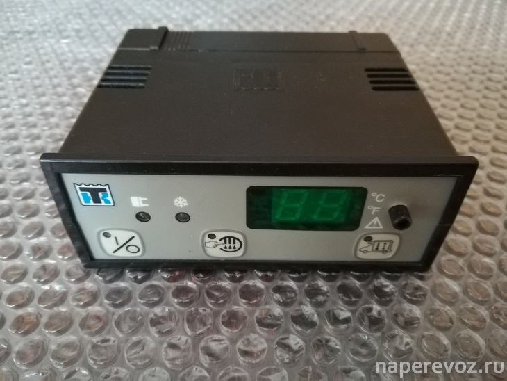
КНОПКИ И ИНДИКАТОРЫ УПРАВЛЕНИЯ
00 Световой индикатор включения; [2] Кнопка включения/выключения; [3) Световой индикатор заданной температуры; [4] Световой индикатор перегрузки по переменному току; [5] Световой индикатор работы установки; [б] Дисплей показаний температуры;0Световой индикатор показания температуры по Цельсию; [8]Световой индикатор показания температуры по Фаренгейту.
Руководство пользователя Thermo King Старых моделей серии V
Руководство пользователя Thermo King Старых моделей серии V
РАБОТА В РЕЖИМЕ ОТТАИВАНИЯ
РУЧНОЕ ВКЛЮЧЕНИЕ РЕЖИМА ОТГАИВАНИЯ*)
При нажатии кнопка ручного включения запускает режим оттаивания, если температура испарителя ниже 2°С или 35°F, при этом светодиод оттаивания должен включиться.
Установка будет работать в режиме охлаждения автоматически, когда цикл оттаивания закончится.
Руководство пользователя Direct Smart Reefer Thermo King Серии V
Руководство пользователя Direct Smart Reefer Thermo King Серии V
Установки с приводом от двигателя автомобиля и контроллером Direct Smart Reefer Руководство по эксплуатации B-100, V-100, V-200, V-300, V-400, V-500, V-700
РУССКИЙ содержание
Руководство оператора пульта управления ThermoGuard uP-T Smart Reefer
Руководство оператораThermoGuard TG-VI
Руководство оператораThermoGuard TG-VI
РАЗДЕЛ I
ПРАВИЛА БЕЗОПАСНОЙ ЭКСПЛУАТАЦИИ
Правила безопасности I-I
Общие правила I-I
Автоматический запуск/остановка I-I
Руководство пользователя Smart Reefer2
Руководство пользователя Smart Reefer2
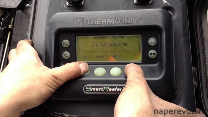
ФУНКЦИИ ПУЛЬТА УПРАВЛЕНИЯ HMI
Пульт управления HMI (Human/Machine Interface) подключен к контроллеру и служит для управления агрегатом и отображения информации . Пульт HMI и контроллер соединены шиной CAN (Controller Area Network) . HMI также включает в себя регистратор данных о температуре груза Cargo Watch . Он расположен на дверце блока управления
Руководство оператора ThermoGuard Spectrum Multi-Temp
Раздел 1 — Информация по техникебезопасности SPECTRUM
Общие правила………………………………………………………………………………………………………………….. 1-1
Автоматический пуск и останов………………………………………………………………………………………… 1-1
Руководство пользователя SLX
SLX-100, 200 и 400 с контроллером SR-2
Введение
Общие сведения………………………………………………………………………………………………………………………………………………………………………….. 4
СЛУЖБА Thermo Assistance…………………………………………………………………………………………………………………………………………………………. 4
Коды ошибок Thermo King
Расшифровка кодов ошибок Thermo King (Термо Кинг)
Инструкции по эксплуатации органов управления Thermo King
Полезная информация о Thermo King
Инструкции по ремонту авторефрижераторов (рефрижераторов) Thermo King (Термо Кинг) на нашем сайте нет.
Инструкции на пульты управления
![]() SR2 — пульт управления авторефрижераторов SLe и SLX
SR2 — пульт управления авторефрижераторов SLe и SLX
![]() ThermoGuard TG-VI
ThermoGuard TG-VI
![]() ThermoGuard uP-T
ThermoGuard uP-T
![]() Spectrum Multi-Temp
Spectrum Multi-Temp
Инструкции на авторефрижераторы
![]() SL-100e, SL-200e, SL-400e и SPECTRUM SL
SL-100e, SL-200e, SL-400e и SPECTRUM SL
![]() SLX-100, 200 и 400 с контроллером SR-2
SLX-100, 200 и 400 с контроллером SR-2
![]() TS-200, TS-300, TS-600, TS-500, SPECTRUM TS, XDS SR, RD-II, KD-II, MD-200, MD-300, MD-II, SDZ, CD-II MAX, UMD-II, URD-III, UTS, RD TLE, MD TLE, RD-MT, MD-MT, MD-200 MT
TS-200, TS-300, TS-600, TS-500, SPECTRUM TS, XDS SR, RD-II, KD-II, MD-200, MD-300, MD-II, SDZ, CD-II MAX, UMD-II, URD-III, UTS, RD TLE, MD TLE, RD-MT, MD-MT, MD-200 MT
![]() T-500R, T-600R, T-800R, T-1000R, T-1200R (1 часть), (2 часть).
T-500R, T-600R, T-800R, T-1000R, T-1200R (1 часть), (2 часть).
![]() UT-800, UT-1200
UT-800, UT-1200
![]() Нового поколения B-100, V-100, V-200, V-300, V-400, V-500, V-700
Нового поколения B-100, V-100, V-200, V-300, V-400, V-500, V-700
![]() Серия — С
Серия — С
![]() Серия — V
Серия — V
- Manuals
- Brands
- Thermo King Manuals
ManualsLib has more than 521 Thermo King manuals
Popular Categories:
![]()
Air Conditioner
![]()
Refrigerator
Accessories
Models
Document Type
Precedent S-600
Operator’s Manual
• Operator’s Manual
Precedent S-700
Operator’s Manual
• Operator’s Manual
Air Compressor
Models
Document Type
X214
Overhaul Manual
X418
Overhaul Manual
X426
Overhaul Manual
X430
Overhaul Manual
Air Conditioner
Models
Document Type
098916
Maintenance Manual
098922
Maintenance Manual
098924
Maintenance Manual
098934
Maintenance Manual
098935
Maintenance Manual
MAGNUM
Maintenance Manual
MAGNUM 20
Maintenance Manual
MAGNUM SL
Maintenance Manual
Precedent S-600
Operator’s Manual
• Operator’s Manual
Precedent S-700
Operator’s Manual
• Operator’s Manual
Show all Thermo King Air Conditioner manuals
Automobile Accessories
Models
Document Type
42-2499
Installation Procedures
B-100
Diagnostic Manual
E-200
Operato’s Manual
• Installation Manual
Precedent C-600M
Installation Manual
• Operator’s Manual
Precedent S-750i
Installation Manual
SB-III 30 SR+
Manual
SLXi Spectrum
Operator’s Manual
• Operator’s Manual
• Maintenance Manual
• Manual
SLXi Spectrum Whisper Pro
Operator’s Manual
• Operator’s Manual
• Maintenance Manual
• Manual
SLXi-100
Operator’s Manual
• Operator’s Manual
• Maintenance Manual
• Maintenance Manual
• Manual
SLXi-200
Operator’s Manual
• Operator’s Manual
• Maintenance Manual
• Maintenance Manual
• Manual
Show all Thermo King Automobile Accessories manuals
Chiller
Models
Document Type
UT-1280
Installation Manual
• Operator’s Manual
Computer Hardware
Models
Document Type
Smart Reefer 2
Driver Manual
Smart Reefer 4
Manual
Sr-2
Manual
SR-3
Manual To Simple Operation
• Driver Manual
• Diagnostic Manual
SR-4
Manual
Control Systems
Models
Document Type
919180
Manual
919181
Manual
919182
Manual
919190
Manual
919191
Manual
919192
Manual
SL-400e
Diagnostic Manual
• Maintenance Manual
SLX Series
Diagnostic Manual
SLXe Series
Diagnostic Manual
SLXi Series
Diagnostic Manual
Show all Thermo King Control Systems manuals
Control Unit
Models
Document Type
920271
Manual
920272
Manual
920273
Manual
920274
Manual
920275
Manual
920276
Manual
V-500
Operator’s Manual
• Manual
• Diagnostic Manual
V-500 MAX-10
Manual
V-500 MAX-20 1PH
Manual
V-500 MAX-20 3PH
Manual
Show all Thermo King Control Unit manuals
Controller
Models
Document Type
ClimaAIRE BEA114
Operator’s Manual
ClimaAIRE I D TK 60065
Operator’s Manual
IntelligAIRE II
Operator’s Manual
Engine
Models
Document Type
SB-400
Manual
Heat Pump
Models
Document Type
Ce-Series
Operator’s Manual
CRR-20
Maintenance Manual
CRR-40
Maintenance Manual
CRR-40 119
Manual
CRR-40 119A
Manual
CRR-40 172
Manual
CRR-40 800
Manual
CRR-40 800E
Manual
CRR-40-139
Maintenance Manual
CRR-40-141
Maintenance Manual
Show all Thermo King Heat Pump manuals
Heater
Models
Document Type
HK450
Installation Manual
• Installation Manual
HK450 HO
Installation Manual
• Installation Manual
HK450 MAX
Installation Manual
• Installation Manual
SB-200TG
Operation Manual
Trailer Edition Heat King 450 Series
Installation Manual
• Installation Manual
Heating System
Models
Document Type
HK-430 HO
Installation Manual
HK450
Installation Manual
• Installation Manual
HK450 HO
Installation Manual
• Installation Manual
HK450 MAX
Installation Manual
• Installation Manual
Trailer Edition Heat King 450 Series
Installation Manual
• Installation Manual
Industrial Equipment
Models
Document Type
MAGNUM PLUS 098212
Maintenance Manual
MAGNUM PLUS 098216
Maintenance Manual
MAGNUM PLUS 098218
Maintenance Manual
MAGNUM PLUS 098219
Maintenance Manual
MAGNUM PLUS 098223
Maintenance Manual
MAGNUM PLUS 098580
Maintenance Manual
MAGNUM PLUS 098581
Maintenance Manual
MAGNUM PLUS 098582
Maintenance Manual
MAGNUM PLUS 098583
Maintenance Manual
MAGNUM PLUS 098585
Maintenance Manual
Show all Thermo King Industrial Equipment manuals
Inverter
Models
Document Type
1100
User Manual
1500
User Manual
2000
User Manual
Laboratory Equipment
Models
Document Type
SG 3500 Series
Maintenance Manual
SGCO-3500
Maintenance Manual
SGUM-3500
Maintenance Manual
Other
Models
Document Type
TouchPrint
User Manual
• User Manual
• Manual
Portable Generator
Models
Document Type
SGCO 3000
Manual
TriPac E
Driver Operating Instructions
TriPac Envidia
Operator’s Manual
• Installation Manual
Printer
Models
Document Type
TouchPrint
User Manual
• User Manual
• Manual
Refrigerator
Models
Document Type
002008
Manual
002009
Manual
002010
Manual
002011
Manual
088669
Manual
088670
Manual
088671
Manual
088672
Manual
088673
Manual
088674
Manual
Show all Thermo King Refrigerator manuals
Remote Control
Models
Document Type
µP-T
Operating Manual
Solar panel
Models
Document Type
Ingersoll Rand NAD 100W
Installation Manual
Ingersoll Rand ThermoLite EMEA 100W
Installation Manual
Ingersoll Rand ThermoLite EMEA 36W
Installation Manual
Ingersoll Rand ThermoLite NAD 36W
Installation Manual
ThermoLite
Installation Manual
ThermoLite 401414
Installation Instructions Manual
ThermoLite T-Series
Installation Manual
Temperature Controller
Models
Document Type
SB-210+
Operator’s Manual
SB-310+
Operator’s Manual
Spectrum DE 30-2
Manual
Spectrum DE 30-3
Manual
Thermostat
Models
Document Type
914 724
Manual
914725
Manual
914728
Manual
914729
Manual
915091
Manual
915094
Manual
915097
Manual
CB MAX 10 12V
Manual
CB MAX 10 24V
Manual
CB MAX 20 12V
Manual
Show all Thermo King Thermostat manuals
Trucks
Models
Document Type
Precedent C-600
Operator’s Manual
T-1000R
Installation Manual
• Manual
• Maintenance Manual
• Operator’s Manual
• Maintenance Manual
T-1200R
Installation Manual
• Manual
• Operator’s Manual
• Maintenance Manual
T-500R
Operator’s Manual
• Maintenance Manual
T-600R
Installation Manual
• Manual
• Maintenance Manual
• Operator’s Manual
• Maintenance Manual
T-800R
Installation Manual
• Manual
• Maintenance Manual
• Operator’s Manual
• Maintenance Manual
Show all Thermo King Trucks manuals
Ventilation Hood
Models
Document Type
CF-II M19.10
Reference Sheet
CF-II M19.7
Reference Sheet
CF-II M19.8
Reference Sheet
CF-II M19.9
Reference Sheet
Water Filtration Systems
Models
Document Type
TriPac DPF
Operator’s Manual
Содержание
- Термокинг рефрижераторы — простота в управлении
- Инструкции на пульты управления
- Инструкции на авторефрижераторы
- Ремонт термокинг
- Температурный контроль в установках термокинг
- Подбор рефрижератора
- Рефрижераторы Thermo King
- Назначение рефрижераторов Thermo King
- Устройство рефрижераторов Термокинг;
- Модельный ряд
- Основные конкуренты
- Коды основных неисправностей и способы устранения
- Заключение
- Рефрижератор Thermo King T-800R
- ТОП-4 рефрижератора Термокинг (Thermo King) и ремонт их неисправностей: освещаем по полочкам
- Причины выхода из строя рефрижераторов
- Коды ошибок Carrier
- Портфолио наших работ
- Неполадки и способы их устранения
- Коды неисправностей для установок Carrier. Действия водителя.
- Ремонт термокинг
- Коды ошибок Thermo King
- Температурный контроль в установках термокинг
- Коды ошибок Carrier
- Подбор рефрижератора
Термокинг рефрижераторы — простота в управлении
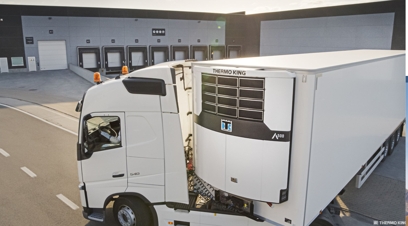
Одноименная компания Thermoking, которая производит термокинг рефрижераторы, была образована еще в 1938-м году. Бренд является лидирующим в сфере выпуска холодильного и отопительного оборудования для транспортных средств. Устройства, выпускаемые заводами Термокинг, устанавливаются на железнодорожные вагоны, автобусы, грузовики и полуприцепы.

Инструкции на пульты управления
Поскольку термокинг рефрижераторы работают при помощи пульта дистанционного управления (сокращенно – ДУ), в комплекте с устройством прилагается подробная инструкция. Она состоит из нескольких глав:
- Главные правила по безопасному использованию. Раздел разбит на дополнительные части, посвященные отдельным составляющим (хладагент, масло, осторожность в работе с электронными частями и так далее).
- Описание назначения каждой кнопки контроллера.
- Объяснение принципов работы и эксплуатация программного обеспечения пульта.
- Правила включения и выключения рефрижератора, отстройка температурного режима, запуск мотора, управление циклами оттайки.
- Обзор основного меню пульта (изменения языка, разбор аварийных кодов).
Документ содержит более 60-ти страниц, поэтому информация в нем излагается предельно подробно. Рекомендуется полностью ознакомиться с руководством. От этого зависит, как безопасность пользователя, так и срок службы приобретенного агрегата.
Инструкции на авторефрижераторы
Подробная инструкция по эксплуатации включает в себя несколько основных моментов, которые необходимо изучить каждому пользователю:
- Сведения о приобретенной модели оборудования. В данном разделе находятся технические характеристики аппарата. Также можно схематично ознакомиться с основными принципами архитектуры модели.
- Правила по технике безопасности. Приложенное руководство эксплуатации рефрижераторных систем позволяет ознакомиться с правилами запуска и использования оборудования.
- Разбор составляющей компрессора. Глава посвящена индивидуальным особенностям сборки узла, а также нюансам функционирования компрессора (расход потока воздуха и так далее).
- Контроллер. Поскольку в комплекте с основным устройством прилагается пульт дистанционного управления, в инструкции описаны назначения всех его клавиш.
- Техническое обслуживание рефрижератора. Подробный порядок действий, описанный в документе, позволяет выполнить качественную диагностику прибора, а также необходимую периодичность.
- Таблички с предупреждениями располагаются ближе к концу.
- Талон гарантийного обслуживания так же прилагается в разделе инструкции.
Ремонт термокинг
Произвести ремонт рефрижераторов можно лишь после обнаружения первопричины поломки. Чаще всего в практике встречается следующий спектр неисправностей:
- Выход из строя пускового механизма. Аппарат не запускается;
- Поломка реле, отвечающего за контроль количества смазки и компрессора;
- Необходимость снижения уставки защитного реле;
- Регулировка давления внутри нагнетающей системы.
Для наибольшего удобства при некорректной эксплуатации на экране пульта рефрижератора высвечиваются следующие коды ошибок:
- Показатели системы не поступают на пульт ДУ, даже если рефрижератор запущен, и продолжает работу.
- Датчик температуры, отслеживающий работу испарительного механизма, вышел из строя.
- Сломан датчик, отвечающий за контроль возвратного потока воздуха.
- Цепь нагнетания воздуха вышла из строя.
- Система определения температуры окружающей среды не работает.
- Сломан механизм контроля охладительной жидкости.
- Датчик оборотов дизельного двигателя неисправен.
Температурный контроль в установках термокинг
Данный процесс выполняется автоматически. Достаточно запустить двигатель, и начать поездку. Нагрев и охлаждение воздуха зависит от заданных водителем настроек. Контроль полный, поэтому не требует вмешательства пользователя. Благодаря этому, любой продукт, находящийся внутри прицепа, не чувствует перепады температуры воздуха за бортом.
Подбор рефрижератора
Характер груза и его объемы – это параметры, позволяющие определить тип нужного авторефрижератора. Каждый продукт обладает своими требованиями к условиям перевозки.
Чтобы обеспечить приемлемые условия, необходимо настроить рефрижератор в соответствии с требованиями. Примером решения универсальных задач является модель v500 max, которая работает с двумя испарителями, чтобы управлять температурой.
Источник
Рефрижераторы Thermo King
Транспортировка продуктов питания требует строгого соблюдения определенного температурного режима, которое возможно только благодаря использованию специальной техники. Изобретение и передвижных холодильных (морозильных) установок в свое время произвело настоящую революцию и позволило в целостности и сохранности доставлять скоропортящиеся грузы на любые расстояния.
Рефрижераторы, а именно такое название получила данная разновидность спецтехники, обрели широкое распространение благодаря удобству и массе дополнительных функций. Достойное место в данном рыночном сегменте занимают рефрижераторы Thermo King. Об их особенностях и преимуществах пойдет речь в нашем сегодняшнем разговоре.
Назначение рефрижераторов Thermo King
Американская компания «Термокинг» занимается производством передвижной холодильной и отопительной техники с 1938 года. Установки, которые сходят с конвейеров ее предприятий, устанавливаются на шасси грузовиков, прицепов и полуприцепов, автобусов, а также на железнодорожные платформы.
Главное назначение подобной техники – регулировка температурного режима, которая в большинстве случаев осуществляется автоматически.
Благодаря созданию и поддержанию внутри установки требуемого диапазона температур стало возможным перемещение на любые расстояния продуктов питания, косметики и парфюмерии, медицинских препаратов, химических веществ, а также приборов, работа которых возможна исключительно при определенных температурных значениях.
Компаниями-партнерами бренда являются такие известные производители автомобильной техники, как Hyundai, МАЗ, Iveco, Isuzu. Оборудование этого производителя устанавливается также на грузовики «КамАЗ», «Валдай», «Газель» и пр.
К неоспоримым его преимуществам необходимо отнести высокую надежность, беспрецедентное качество, продолжительный срок службы, надежную защиту груза от любых повреждений в процессе транспортировки, оперативность и простоту монтажа установок на шасси различных ТС, экономичность использования. Что касается недостатков, то существенных минусов, которые заслуживали бы пристального внимания, на момент подготовки данного материала обнаружено не было.

Ассортимент «Термо Кинг» включает следующие модули:
- Автономные устройства.
- Системы, работающие от привода двигателя транспортного средства, на шасси которого они установлены.
- Установки, разработанные для монтажа на полуприцепы.
- Эвтектические системы.
Устройство рефрижераторов Термокинг;
Рефрижератор «Термо Кинг» представляют собой бокс в металлическом каркасе со стенами из сендвич-панелей, обладающих определенными теплосберегающими характеристиками. Снаружи панели покрыты дюралевыми металлическими листами, которые, помимо всего прочего, служат для дополнительной защиты от механических воздействий.
Изнутри бокс отделан профлистом, в нем имеются стоки для отвода конденсата и талой воды, если она образовалась в процессе эксплуатации. Температура регулируется посредством пульта управления, как правило, устанавливается он в одной из стенок фургона.
Принцип работы компрессоров Thermo King предельно прост: охлажденный до необходимой температуры воздух подается из рефрижераторной системы в фургон и распределяется по всей его площади. С помощью пульта можно настраивать скорость циркуляции воздушных потоков, регулировать температуру и уровень влажности. В случае необходимости активизируется режим оттайки с дальнейшей заморозкой. Если говорить о ключевых элементах рефрижераторных установок, то это следующие составляющие:
- хладагент (необходим для повышения или понижения температуры);
- испаритель (его функция – нейтрализация тепла);
- теплообменные катушки (перемещают хладагент по корпусу установки);
- компрессор («сердце» данного оборудования, без него невозможно изменение температуры хладагента и его давления).
Модельный ряд
На современном рынке техника бренда «Термо Кинг» представлена устройствами нескольких серий. Так, к примеру, серия V – это высокопроизводительное оборудование с плоскими испарителями, которое может использоваться также для поддержания требуемого температурного режима еще и в водительской кабине. Серия С была создана для эксплуатации в условиях жаркого климата.
Приборы оснащены мощными вентиляторами, которые способствуют оперативному и равномерному распределению воздушных потоков внутри корпуса, а также термостатами, позволяющими зафиксировать и поддерживать температуру на одном уровне. Все устройства данной серии снабжаются автоматическим режимом оттаивания.
Серия Т – это моноблоки, работающие на дизтопливе и управляемые «умным» контроллером, который можно настроить в соответствии с потребностями пользователя, а приборы SLXe-серии характеризуются оптимальным сочетанием высокой производительности и бесшумности работы. Они применяются для перевозки небольшой партии замороженных продуктов в обычном автомобильном кузове.
Поговорим о каждой из перечисленных серий более детально.
Серия V
Оборудование данной серии способно работать при температуре в диапазоне -20 — +12 градусов Цельсия. Необходимо подключение к двигателю автомобиля, на шасси которого смонтирована установка. Модели с литерой V в названии характеризуются высочайшей точностью настроек – регулировать температурный режим можно вплоть до одной десятой градуса.
Удобству эксплуатации способствует тот факт, что пульт управления располагается в кабине водителя. Некоторые модели позволяют зонировать кузов, создавая в разных его углах различную температуру.
Серия C
Рефрижераторы этой серии поддерживают температуру на уровне +3 градуса, работают они только на охлаждение, обогрев кузова функционалом не предусмотрен. Возможности регулировки температурного режима нет, температура стабильна, выставляется она на этапе монтажа оборудования.
Серия T
Под ней подразумеваются крупногабаритные установки, которые монтируются на машины большой грузоподъемности. Характеризуются полной автономностью, оснащаются отдельной силовой установкой и могут поддерживать температуру в диапазоне от -20 до +12 градусов.
Серия SLXe
Описывая характеристики Thermo King данной серии, важно упомянуть тот факт, что функционируют они с прицепами и полуприцепами, а также оборудуются автономными дизельными моторами. Управлять температурой можно из водительской кабины, причем, высокая точность пульта обеспечивает возможность регулировки вплоть до одной десятой градуса.
Основные конкуренты
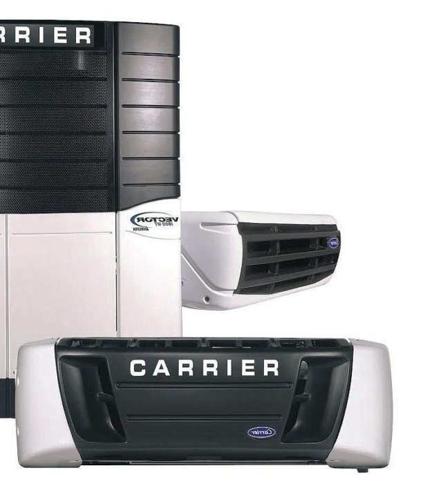
Главным конкурентом «Термо Кинг» является японская компания Daikin, изготавливающая высокотехнологическое холодильное и морозильное оборудование со схожими показателями производительности и функционала.
Неплохо зарекомендовали себя и рефконтейнеры Carrier – «соотечественники» Thermo King, которые выпускаются на заводах, расположенных в американском штате Коннектикут. В тройку лидеров входит и аналогичное оборудование от Star Cool – дочернего предприятия транснациональной корпорации MAERSK.
Коды основных неисправностей и способы устранения
Холодильное оборудование «Термокинг» без преувеличения считается одним из лучших в данном рыночном сегменте, но оно нуждается в своевременном обслуживании и квалифицированном плановом ремонте. Периодически на дисплее появляются непонятные обозначения, это ошибки Thermo King, так называемые коды неисправностей, в которых могут разобраться только специалисты.
Чтобы понять, что обозначает тот или иной код, можно воспользоваться таблицей, коих в интернете достаточно. Перечислять все не имеет смысла, так как для этого не хватит и отдельной статьи, в качестве примера приведем только несколько:
- 06 – проблемы с работой датчика температуры хладоносителя.
- 10 – давление нагнетателя превышено.
- 03 или 04 – проблемы в работе датчиков возвратного и нагнетаемого воздуха соответственно.
- 09 – превышена температура испарителя.
В списке кодов – 250 позиций, устранить самые распространенные неисправности способны опытные водители.
Если же подобных умений и опыта у пользователя нет, при обнаружении любых неполадок необходимо обратиться в специализированный сервисный центр, предоставляющий услуги по ремонту и обслуживанию рефрижераторных установок.
Заключение
Темой нашего материала стали холодильные установки, пользующиеся на современном рынке высочайшим спросом в виду надежности, удобства эксплуатации, широкого функционала и превосходного качества. Однако для того, чтобы оборудование служило годами, справляясь со своими функциями надлежащим образом, оно нуждается в квалифицированном и своевременном техобслуживании.
Рефрижератор Thermo King T-800R
Источник
ТОП-4 рефрижератора Термокинг (Thermo King) и ремонт их неисправностей: освещаем по полочкам

Одноименная компания Thermoking, которая производит термокинг рефрижераторы, была образована еще в 1938-м году. Бренд является лидирующим в сфере выпуска холодильного и отопительного оборудования для транспортных средств. Устройства, выпускаемые заводами Термокинг, устанавливаются на железнодорожные вагоны, автобусы, грузовики и полуприцепы.
Причины выхода из строя рефрижераторов
Что делать, если система глохнет, не заводится или наоборот не выключается? Как разобраться в причинах возникшей неполадки? Системы охлаждения выходят из строя из-за:
- обрыва приводного ремня компрессора;
- утечки хладагента из-за разгерметизации;
- неполадок в электропроводке;
- сбоев в системе управления.
Несвоевременная чистка установки, замена хладагента и масла – приводит к тому, что рефрижератор сначала начнет глохнуть, а потом совсем перестанет включаться. Пользователям необходимо внимательно отслеживать работу сплит-системы и при выявлении ошибок незамедлительно устранять их.

Коды ошибок Carrier
Эта информация является ознакомительной. Рекомендуем при первой возможности обратиться в сервис для устранения и диагностики неисправности
Портфолио наших работ
Будем рады обрести в Вашем лице любимого клиента и надежного партнера на долгие годы! Обращайтесь!
Неполадки и способы их устранения
Когда система глохнет замена масла или фреона не поможет. Встречаются следующие виды неисправностей, которые приводят к незапланированному выключению и проблемам с включением установки.
- Неисправности электрической схемы. Компрессор будет постоянно глохнуть или не включаться. От пользователя требуется проверить предохранители, пускатели электродвигателя, целостность цепей управления и работоспособность реле, исправность электрической проводки. Вышедшие из строя детали и элементы необходимо заменить.
- Низкое напряжение на клеммах агрегата и вышедший из строя конденсатор будут провоцировать частое отключение установки.
- Избыточное давление, низкое или высокое давление всасывания. Для устранения потребуется удалить избыток хладагента в системе и обеспечить достаточный обдув воздухом наиболее важных узлов.
- Перегрев корпуса компрессора, перегоревшая обмотка электродвигателя – восстановить работоспособность можно после замены компрессора.
- Неисправности в работе реле высокого и низкого давления, реле регулировки температуры.
Гораздо реже причиной частого выключения рефрижератора ТермоКинг становится чрезмерное загрязнение испарителя льдом или проблемы на линии циркуляции воды. Для оперативного устранения ошибок и неполадок в работе необходимо обратиться в сервисную службу производителя.
Коды неисправностей для установок Carrier. Действия водителя.

Коды неисправностей рефрижераторных установок Carrier Transicold с системой управления LogiCold.
| CODE | ENGLISH | ОПИСАНИЕ |
| AL0 | ENG OIL | Низкое давление масла |
| AL1 | ENG HOT | Высокая температура охлаждающей жидкости |
| AL2 | HI PRESS | Высокое давление |
| AL3 | STARTFAIL | Неисправность при автоматическом пуске |
| AL4 | LOW BATT | Низкое напряжение батареи |
| AL5 | HI BATT | Высокое напряжение батареи |
| AL6 | DEFRFAIL | Отмена оттаивания |
| AL7 | ALT AUX | Дополнительный выход генератора |
| AL8 | STARTER | Стартер |
| AL9 | RA SENSOR | Датчик поступающего воздуха |
| AL10 | SA SENSOR | Отказ датчика температуры SAS |
| AL11 | WT SENSOR | Отказ датчика температуры двигателя |
| AL12 | HIGH CDT | Высокая температура нагнетания компрессора> |
| AL13 | CD SENSOR | Не используется |
| AL14 | SBY MOTOR | Перегрузка электромотора |
| AL15 | FUSE BAD | Сгорел предохранитель |
| AL17 | DISPLAY | Отказ дисплея или повреждение шины между дисплеем и процессором |
| AL18 | SERVICE 1 | Необходимо сервисное обслуживание №1 |
| AL19 | SERVICE 2 | Необходимо сервисное обслуживание №2 |
| AL20 | RAS OUT | Температура в кузове «вне допуска |
Информация о работе рефрижераторных агрегатов Carrier Transicold с системой управления LogiCold. (может быть получена нажатием клавиши Unit Data)
| CODE | ENGLISH | ОПИСАНИЕ |
| CD1 | SUST | Давление всасывания фреона |
| CD2 | ENG | Моточасы дизеля |
| CD3 | WT | Температура охлаждающей жидкости дизеля |
| CD4 | RAS | Температура воздуха на входе в испаритель |
| CD5 | SAS | Температура подаваемого воздуха |
| CD6 | REM | Температура воздуха по доп. датчику |
| CD7 | ATS | Наружная температура |
| CD8 | EVP | Резерв |
| CD9 | CDT | Температура нагнетания компрессора |
| CD10 | BATT | Напряжение АКБ |
| CD11 | SBY | Моточасы электромотора |
| CD12 | MOD V | Не используется |
| CD13 | REV | Версия программы |
| CD14 | SER L | Низшие разряды серийного номера процессора |
| CD15 | SER U | Высшие разряды серийного номера процессора |
| CD16 | 2 RA | Температура во втором отсеке |
| CD17 | 3 RA | Температура в третьем отсеке |
| CD18 | MHR 1 | Счётчик обслуживания №1 |
| CD19 | MHR 2 | Счётчик обслуживания №2 |
| CD20 | SON | Счётчик общего времени работы процессора |
Коды неисправностей рефрижераторных установок Carrier XARIOS.
Нажмите клавишу SET в течении 5 секунд — разрешается доступ к кодам неисправностей. Текущие неисправности — AXX. Ранее зарегистрированные неисправности — PXX. При возникновении неисправности мигает красный индикатор кодов неисправностей.
| A00 | Неисправности отсутствуют. Агрегат работает |
| A01 | Разомкнуто реле низкого давления |
| A02 | Разомкнуто реле высокого давления |
| A03 | Перегрев стояночного комрессора |
| A04 | Неисправность муфты компрессора |
| A05 | Неисправность выключателя |
| A06 | Неисправность вентилятора конденсатора |
| A07 | Неисправность вентилятора испарителя |
| A08 | Неисправность электромагнитного клапана горячей жидкости |
| A09 | Неисправность клапана оттаивания(HGS1) |
| A10 | Неисправность клапана ;blrjcnb |
| A11 | Неисправность клапана горячего газа(HGS2) |
| A12 | Аварийный сигнал высокой температуры в кузове |
| A13 | Аварийный сигнал низкой температуры в кузове |
| A14 | Аварийный сигнал продолжительности оттаивания > 45 минут |
| A15 | Заданное значение установлено вне диапазона -29°C/ +30°C |
| A16 | Неисправность обогревателя сливных шлангов |
| A17 | Сработала тепловая защита стояночного трансформатора |
| A18 | Неисправность реле электроподогрева |
| A19 | Неисправность электромагнитного клапана жидкости |
| A21 | Обрыв цепи выключателя компрессора |
| A22 | Обрыв цепи вентилятора конденсатора |
| A23 | Обрыв цепи электромагнитного клапана горячей воды |
| A24 | Обрыв цепи клапана оттаивания(HGS1) |
| A25 | Обрыв цепи клапана впрыска жидкости |
| A26 | Обрыв цепи клапана горячего газа(HGS2) |
| A27 | Обрыв цепи обогревателя сливных шлангов(DWR1) |
| A28 | Обрыв цепи реле электроподогрева(EHR) |
При одновременном возникновении нескольких неисправностей просмотрите их с помощью клавиш — и +.
| EE | Неисправность датчик температуры испарителя(обрыв цепи) |
| bAt | Аварийный сигнал низкого напряжения аккумулятора батареи |
| Err | Ошибка программирования пользователем максимального заданного значения |
Коды ошибок Carrier, ThermoKing. Самостоятельная диагностика
Ремонт термокинг
Произвести ремонт рефрижераторов можно лишь после обнаружения первопричины поломки. Чаще всего в практике встречается следующий спектр неисправностей:
- Выход из строя пускового механизма. Аппарат не запускается;
- Поломка реле, отвечающего за контроль количества смазки и компрессора;
- Необходимость снижения уставки защитного реле;
- Регулировка давления внутри нагнетающей системы.
Для наибольшего удобства при некорректной эксплуатации на экране пульта рефрижератора высвечиваются следующие коды ошибок:
- Показатели системы не поступают на пульт ДУ, даже если рефрижератор запущен, и продолжает работу.
- Датчик температуры, отслеживающий работу испарительного механизма, вышел из строя.
- Сломан датчик, отвечающий за контроль возвратного потока воздуха.
- Цепь нагнетания воздуха вышла из строя.
- Система определения температуры окружающей среды не работает.
- Сломан механизм контроля охладительной жидкости.
- Датчик оборотов дизельного двигателя неисправен.
Коды ошибок Thermo King
Эта информация является ознакомительной. Рекомендуем при первой возможности обратиться в сервис для устранения и диагностики неисправности
Температурный контроль в установках термокинг
Данный процесс выполняется автоматически. Достаточно запустить двигатель, и начать поездку. Нагрев и охлаждение воздуха зависит от заданных водителем настроек. Контроль полный, поэтому не требует вмешательства пользователя. Благодаря этому, любой продукт, находящийся внутри прицепа, не чувствует перепады температуры воздуха за бортом.
Коды ошибок Carrier
Эта информация является ознакомительной. Рекомендуем при первой возможности обратиться в сервис для устранения и диагностики неисправности
Подбор рефрижератора
Характер груза и его объемы – это параметры, позволяющие определить тип нужного авторефрижератора. Каждый продукт обладает своими требованиями к условиям перевозки.
Чтобы обеспечить приемлемые условия, необходимо настроить рефрижератор в соответствии с требованиями. Примером решения универсальных задач является модель v500 max, которая работает с двумя испарителями, чтобы управлять температурой.
Источник
- Manuals
- Brands
- Thermo King Manuals
- Refrigerator
- CSR Series
- Manual
-
Contents
-
Table of Contents
-
Bookmarks
Quick Links
CSR
TK 50824-4-MM (Rev. 6, 11/02)
©
Copyright
2002 Thermo King Corp., Minneapolis, MN, U.S.A.
Printed in U.S.A.
Related Manuals for Thermo King CSR Series
Summary of Contents for Thermo King CSR Series
-
Page 1
TK 50824-4-MM (Rev. 6, 11/02) © Copyright 2002 Thermo King Corp., Minneapolis, MN, U.S.A. Printed in U.S.A. -
Page 2
If further information is required, Thermo King Corporation should be consulted. Sale of product shown in this manual is subject to Thermo King’s terms and conditions including, but not limited to, the Thermo King Limited Express Warranty. Such terms and conditions are available upon request. -
Page 3
Recover Refrigerant At Thermo King, we recognize the need to preserve the environment and limit the potential harm to the ozone layer that can result from allowing refrigerant to escape into the atmosphere. We strictly adhere to a policy that promotes the recovery and limits the loss of refrigerant into the atmosphere. -
Page 5: Table Of Contents
Table of Contents List of Figures …………….11 Safety Precautions .
-
Page 6
Table of Contents MP-3000 Controller …………..55 Controller Description . -
Page 7
Table of Contents MP-3000 Controller (continued) Datalogger Menu …………… . 95 Viewing the Datalogger Menu . -
Page 8
Table of Contents Refrigeration Maintenance and Service Operations (continued) Evacuation and Cleanup of the Refrigeration System ……….139 Compressor Oil Color Code . -
Page 9
Table of Contents Structural/Accessory Maintenance …………151 Mounting Bolts . -
Page 10
Table of Contents… -
Page 11: List Of Figures
List of Figures Figure 1:Nameplate and Warning Locations ……….. 16 Figure 2:Physical Specifications .
-
Page 12
List of Figures Figure 50:Evacuation Station and Unit Hook-up ……….141 Figure 51:Constant Pressure Rise After Evacuation Indicates System Leak . -
Page 13: Safety Precautions
Safety Precautions General Practices Refrigerant 1. Always wear goggles or safety glasses. When removing any refrigerant from a unit, use a Refrigerant liquid and battery acid can recovery process that prevents or absolutely permanently damage the eyes (see First Aid minimizes the refrigerant that can escape to the under Refrigerant Oil).
-
Page 14: Electrical
Safety Precautions Use the following First Aid practices if needed. • Never work alone on high voltage circuits on the refrigeration unit. Another person should Immediately flush eyes with large amounts Eyes: always be standing by in the event of an of water for at least 15 minutes while holding the accident to shut off the refrigeration unit and eyelids open.
-
Page 15: Servicing Units (Or Containers) Equipped With A Microprocessor Controller
Safety Precautions Low Voltage 5. Leave the circuit boards in their static proof packing materials until ready for installation. Control circuits are low voltage (24 Van and 12 Vdc). This voltage potential is not considered 6. If a defective controller is to be returned for dangerous, but the large amount of current repair, it should be returned in the same static available (over 30 amperes) can cause severe…
-
Page 16: Unit Decals
Serial number decals, refrigerant type decals and • Compressor: Nameplate on front of the ® warning decals appear on all Thermo King compressor. equipment. These decals provide information that may be needed to service or repair unit. Service •…
-
Page 17: Service Guide
Service Guide Every Annual/ Pre-trip 1,000 Inspect/Service These Items Yearly Hours Electrical • Perform a controller pre-trip inspection (PTI) check. • • • Visually check condenser fan and evaporator fan • • • Visually inspect electrical contacts for damage or loose connections. •…
-
Page 18
Service Guide… -
Page 19: Specifications
Specifications System Net Cooling Capacity— Full Cool CSR20SL Models — Air Cooled Condensing* 460/230V, 3 Phase, 60 Hz Power 380/190V, 3 Phase, 50 Hz Power Return air to Net Cooling Capacity Power Consp Net Cooling Capacity Power evaporator coil Consp inlet Watts Kcal/hr…
-
Page 20: Evaporator Airflow
Specifications Evaporator Airflow Model CSR20SL 460/230V, 3 Phase, 60 Hz Power 380/190V, 3 Phase, 50 Hz Power External Static High Speed Low Speed High Speed Low Speed Pressure (water column) /min /min /min /min 0 mm (0 in.) 4,000 2,350 2,000 1,180 3,300…
-
Page 21: Electrical System
Specifications Electrical System Compressor Motor: Type 460/380V, 60/50 Hz, 3 Phase Kilowatts 4.48 kW @ 460V, 60 Hz Horsepower 6.0 hp @ 460V, 60 Hz 3550 rpm @ 460V, 60 Hz Locked Rotor Amps 70 amps @ 460V, 60 Hz Condenser Fan Motor: Type 460/380V, 60/50 Hz, 3 Phase…
-
Page 22: Refrigeration System
Specifications Electrical System (Continued) Electrical Resistance Heater Rods: Type 460/380V, 60/50 Hz, 3 Phase Number Watts (Each) 680 Watts @ 460V, 60 Hz 5 amps total @ 460V across each phase at heater Current Draw (Amps) contractor Control Circuit Voltage: 29 Vac @ 60 Hz 24 Vac @ 50 Hz Evaporator Overheat Switch:…
-
Page 23: Normal R-404A System Operating Pressures (Scroll Compressor)
Specifications Refrigeration System (Continued) Liquid Injection Valve (Compressor): Voltage 24 Vac Current 0.85 amps Cold Resistance 5.6 ohms Warm Gas Bypass Solenoid Valve: Voltage 24 Vac Current 0.85 amps Cold Resistance 5.6 ohms Stepper Valve Regulating Motor: Voltage 12 Vdc Current Draw 0.13 to 0.21 amperes per winding 0.26 to 0.44 amperes with 2 windings energized…
-
Page 24: Mp-3000 Controller
Specifications MP-3000 Controller Temperature Controller: MP-3000 microprocessor with thermostat, digital thermometer, Type programming keypad, mode indicators, LED display and LCD display for displaying unit operating and cargo information Setpoint Range -30.0 to +30.0 C (-22.0 to +86.0 F) Digital Temperature Display -60.0 to +80.0 C (-76.0 to +176.0 F) Controller Software (Original Equipment): Version…
-
Page 25: Dehumidify And Humidify Systems (Options)
Specifications MP-3000 Controller (Continued) Compressor Shutdown Protection (Auto Reset): Stops Compressor 148 C (298 F) Allows Compressor Start 90 C (194 F) Bulb Mode (Option): Flow High: High speed only; Flow Low: Low speed only Evaporator Fan Speed Settings Flow Cycle: Fans will cycle between low and high speed every 60 minutes Defrost Termination Temperature Setting 4 to 30 C (40 to 86 F)
-
Page 26: Physical Specifications
Specifications Physical Specifications Fresh Air Exchange Venting System (Adjustable): 0 to 160 m /hr (0 to 96 ft /min.) @ 60 Hz CSR20SL 0 to 134 m /hr (0 to 79 ft /min.) @ 50 Hz 0 to 280 m /hr (0 to 165 ft /min.) @ 60 Hz CSR40SL and CSR40…
-
Page 27: Figure 2:Physical Specifications
Specifications AXA0220 Figure 2: Physical Specifications…
-
Page 28: Metric Hardware Torque Charts
Specifications Metric Hardware Torque Charts Bolt Size Bolt Type and Class* N.m (Ft.-lb.) N.m (Ft.-lb.) N.m (Ft.-lb.) N.m (Ft.-lb.) HH – CL 5.8 6-9 (4-7) 12-16 (9-12) 27-34 (20-25) 48-61 (35-40) HH – CL 8.8 10-13 (7-10) 20-27 (15-20) 41-47 (30-35) 75-88 (55-65) HH –…
-
Page 29: Unit Description
Unit Description General Description control sensor temperature (return or supply air temperature). A 4-line, 20-character LCD display Model CSR20SL, CSR40SL and CSR40 units are (bottom) display shows important data including all-electric, single-piece, refrigeration units with the setpoint temperature, controller main menu bottom air supply.
-
Page 30: Dual Speed Evaporator Fans
Unit Description A high speed serial communication port provides door control module to position to vent door to the data retrieval using a DRU-II hand-held data desired position. The controller can also be set to retriever or laptop computer with SmartSponge™ delay opening of the fresh air vent for up to 72 software, or a REFCON power line remote hours, in 1-hour increments.
-
Page 31: Dual Voltage
Unit Description Dual Voltage high ambient temperatures, salt water, humidity, fungus, industrial pollutants, dynamic loading, A dual voltage system includes a 15 KVA auto rain, sand and dust. transformer and an 18.3 m (60 ft.) power cable for operation on 230-190V/3 Ph/60-50 Hz power. The •…
-
Page 32: Water-Cooled Condenser/Receiver Tank
Unit Description When USDA sensors are installed, the controller be in by comparing the setpoint to the return or will automatically detect each sensor and activate supply air temperature. The unit operates in either data logging. However, the USDA Type screen in the Fresh (Chill) or Frozen mode.
-
Page 33: Figure 3:Typical Unit Front View
Unit Description AXA0221 CSR20SL & CSR40SL: Evaporator Access Door, 1399 mm (55.04 in.) Wide with three latches CSR40: Evaporator Access Door, 1018 mm (40.08 in.) Wide with two latches Heater Access Panel Location (CSR20SL-144 , CSR20SL-155 , CSR40-145 & CSR40SL-506 Models Only) Condenser Fan Compressor Compartment Supply Air Sensor Probe Holder, Left Hand (Behind Compressor)
-
Page 34: Figure 4:Evaporator Front View — Csr20Sl & Csr40Sl
Unit Description AXA0222 Evaporator Fan Blade (see “Physical Specifications” on page 26 for description) Evaporator Fan Motor Return Air Sensor Figure 4: Evaporator Front View — CSR20SL & CSR40SL…
-
Page 35: Figure 5:Evaporator Front View — Csr40
Unit Description AXA0224 Return Air Sensor Evaporator Fan Blade (see “Physical Specifications” on page 26 for description) Evaporate Fan Motor Figure 5: Evaporator Front View — CSR40…
-
Page 36: Figure 6:Options — Unit Front View
Unit Description AXA0226 Recording Thermometer Option Suction Pressure Gauge Option Discharge Pressure Gauge Option Dual Voltage Option TRANSFRESH Download Receptacle Option, see “TRANSFRESH System, Complete” on page 47 Remote Monitor Plug Option (4-Pin Connector on Side of Control Box) Thermistor Lead Option (Lead inside Control Box) Remote Monitor Modem for Power Line Communications (REFCON control modem inside Control Box) USDA Sensor Receptacle Option (Access from Inside Container) Advanced Fresh Air Management (see “Advanced Fresh Air Management (AFAM) Option”…
-
Page 37: Figure 7:Csr20Sl, Csr20Sl, Csr40Sl & Csr40Sl Options — Evaporator Front View
Unit Description AXA0227 Sensing Bulb Option for Recording Thermometer (Return Air) Gas Sensor Unit for AFAM+ Option, see page 45 Filter for Gas Sensor for AFAM+ Option Vent Loop for Gas Sensor for AFAM+ Option Air Compressor for Humidity System Option, see 43 Humidity Sensor for Dehumidify Option or Humidity Option Figure 7: CSR20SL, CSR20SL, CSR40SL &…
-
Page 38: Figure 8:Csr40 & Csr40 Options — Evaporator Front View
Unit Description AXA0228 Sensing Bulb Option for recording Thermometer (Return Air) Gas Sensor Unit for AFAM+ Option, see page 45 Vent Loop for Gas Sensor for AFAM+ Option Filter for Gas Sensor for AFAM+ Option Humidity Sensor for Dehumidify Option or Humidity Option Air Compressor for Humidity System Option, see page 43 Figure 8: CSR40 &…
-
Page 39: Figure 9:Refrigeration System
Unit Description AXA0229 Evaporator Coil Scroll Compressor (See page 40) Coil/Dehumidify Valve 10. Discharge Tube (After 7/00) Discharge Tube with High Pressure Cutout Expansion Valve (Before 8/00) Heat Exchanger 12. Condenser Coil One-piece Filter Drier/In-line Filter 13. High Pressure Relief Valve Stepper Motor Valve 14.
-
Page 40: Figure 10:Scroll Compressor
Unit Description AXA0230 Compressor Discharge Temperature Sensor Suction Service Valve (Option) with Service Fitting Compressor Oil Sight Glass Compressor Oil Fitting Discharge Service Valve (Option) with Service Fitting High Pressure Cutout Switch (Units After 7/00) Figure 10: Scroll Compressor…
-
Page 41: Figure 11:Mp-3000 Controller
Unit Description AXA0231 Remote Monitoring Modem (RMM) Option Cable No. 1 Connection to Controller Communication Cable for RMM Option Control Box Cover and Controller Keyboard Decal Control Circuit Fuses, 2 ampere (2) Special Function Keypad Battery Cable Connection to Controller General Purpose Keypad LCD Display (Setpoint Temperature, Message and Cable No.
-
Page 42: Figure 12:Unit Control Box
Unit Description AXA0232 Switch Main Relay Board Remote Monitor, 4-Pin (Option) 12 Vdc Battery Communications Connector for Data Retrieval Control Power Transformer Circuit Breaker 10. Compressor Contactors (2) Communications Cable for AFAM Option and 11. 25 Ampere Main Power Circuit Breaker AFAM+ Option Interface Board for AFAM Option and AFAM+ Option Figure 12: Unit Control Box…
-
Page 43: Figure 13:Humidify System Option
Unit Description AXA0233 Evaporator Drain Hose Water Tank Fill Cap Water Filter Water Tank Heater Water Supply Hose Tank Overflow Hose Air Compressor Drain Cock 10. Liquid Spray Nozzle Figure 13: Humidify System Option…
-
Page 44: Figure 14:Advanced Fresh Air Management (Afam) Option
Unit Description AXA0234 Gasket Interface Board and Cable (Mounts in Control Box), see page 42 Vent Door Assembly Stop Bracket, Vent Door Full Open Linkage Assembly Stop Bracket, Vent Door Closed Damper Motor Housing Grille Damper Motor Assembly Mounting Bracket Figure 14: Advanced Fresh Air Management (AFAM) Option…
-
Page 45: Figure 15:Advanced Fresh Air Management (Afam+) Option
Unit Description AXA0235 Gas Sensor Assembly (Mounts in Evaporator), Damper Motor Assembly Mounting Bracket see page 37 or 38 Gasket Interface Board and Cable (Mounts in Control Box), see page 42 Vent Door Assembly Stop Bracket, Vent Door Full Open Linkage Assembly Stop Bracket, Vent Door Closed Damper Motor Housing…
-
Page 46: Figure 16:Transfresh Provision Option
Unit Description AXA0236 TRANSFRESH Box in Evaporator Grille A2 Wire Harness to TRANSFRESH Transformer A3 Wire Harness to TRANSFRESH Download Port Purge Port Figure 16: TRANSFRESH Provision Option…
-
Page 47: Figure 17:Transfresh System, Complete
Unit Description AXA0237 TRANSFRESH Scrubber Connection and A5 Wire Harnesses Evaporator Grille TRANSFRESH Security Enclosure Transformer Assembly mounted in Control Box TRANSFRESH Download Port Purge Port Figure 17: TRANSFRESH System, Complete…
-
Page 48: Figure 18:Unit Back View — All Models Without Heater Access Door
Unit Description AXA0238 Evaporator Grille Air Channels Fresh Air Inlet Top Rear Plate Bottom Rear Plate Receptacle Panel: • Controller Communications and Data Download Port • USDA1/Spare 1 Sensor Connection • USDA2/Spare 2 Sensor Connection • USDA3/Spare 3 Sensor Connection Figure 18: Unit Back View —…
-
Page 49: Figure 19:Unit Back View — Models With Heater Access Door (Csr20Sl-144 , Csr40-145, Csr20Sl-155 And Csr40Sl-506)
Unit Description AXA0239 Evaporator Grille Air Channels Top Rear Plate Bottom Rear Plate Receptacle Panel: • Controller Communications and Data Download Port • USDA1/Spare 1 Sensor Connection • USDA2/Spare 2 Sensor Connection • USDA3/Spare 3 Sensor Connection Figure 19: Unit Back View — Models with Heater Access Door (CSR20SL-144 , CSR40-145, CSR20SL-155 and CSR40SL-506)
-
Page 50
Unit Description… -
Page 51: Operating Instructions
Operating Instructions Unit Controls 5. Status Indicator LEDs located in the large LED display signal: Unit Control Box • (Air Temperature) UPPLY Switch: • (Air Temperature) ETURN 1. O position. Unit will operate on Cool or Heat • (Humidification Option UMIDITY depending on the controller setpoint set to On…
-
Page 52: Other Unit Controls
Operating Instructions Other Unit Controls Unit Instruments 1. Evaporator Overheat Switch: A temperature 1. Compressor Oil Sight Glass: A compressor oil switch near the evaporator coil opens to sight glass indicates the relative level of de-energize the heater contactor if the compressor oil in the compressor sump.
-
Page 53: Unit Protection Devices
Operating Instructions Unit Protection Devices NOTE: Controller also energizes the liquid injection valve when cooling capacity is 83% 1. Main Circuit: A 25 ampere manual reset or less. Controller de-energizes the valve circuit breaker protects the 460/380V power when cooling capacity is 84% or more. supply circuit to the unit electric motors and b.
-
Page 54
Operating Instructions… -
Page 55: Mp-3000 Controller
MP-3000 Controller Controller Description The MPC-3000 is an advanced microprocessor controller that has been specially developed for the control and monitoring of refrigeration units. The controller contains the following basic features: 1. LED display for Temperature: • Five alpha numeric, 20.32 mm high characters: Numerical hundredths, tens, ones and tenths position, a C for Celsius or F for Fahrenheit for temperature display.
-
Page 56
MP-3000 Controller F3 key: Press the F3 key, then press • 4. Four special function keys (see illustration on another general purpose key to enter 55): the second letter shown on the key. • C/F key: Press to view alternate F4 key: Press the F4 key, then press •… -
Page 57
MP-3000 Controller • Control circuit fuse and circuit breaker 15. Power limit control (see “Power Limit Mode” protection: in this chapter). • 7 amp manual reset circuit breaker 16. Sequential component start-up control: A protects the 24 Vdc control circuit. sequence start of the required loads occurs during initial start-up of the controller and •… -
Page 58: Status Indicator Leds
MP-3000 Controller 21. Display menus: The MPC-3000 controller • Data logger Menu: Menu screens in this contains an extensive display menu that can be group display temperature log, event log, navigated via keypad. The display menu is set log time and PTI log. organized into eight main menus: •…
-
Page 59: Data Recording And Downloading Data
MP-3000 Controller Data Recording and contents, loading data, voyage no., ship, load port, discharge port and comments. The container ID Downloading Data number is stored in the Configuration submenu. The MP-3000 data logger can record sensor temperatures as well as loss of power, alarms, General Theory Of Operation sensor failure, setpoint change and unit shutdown events.
-
Page 60: Chill Loads: (Setpoint At -9.9 C [14.1 F] And Above)
MP-3000 Controller Chill Loads: (Setpoint at -9.9 C Supply Air Sensor Control [14.1 F] and Above) Temperature control accuracy and protection The unit operates on Cool with Modulation and against frost damage is provided by using two Heat to provide accurate control of chill loads. separate sensors (left hand and right hand) to During Cool with Modulation, the controller uses determine the supply temperature used to…
-
Page 61: Frozen Loads: (Setpoint At -10 C [14 F] And Below)
MP-3000 Controller Frozen Loads: (Setpoint at -10 C feature of the Commands menu. When the power [14 F] and Below) management time interval expires, the unit returns to the standard power limit control algorithm. The unit operates on Full Cool and Null to NOTE: Setting power management current at 13 provide accurate control of frozen cargo.
-
Page 62: Power Limit Mode
MP-3000 Controller Power Limit Mode state timer automatically re-starts the evaporator fans on low speed for 5 minutes The controller uses the total unit current and the every 45 minutes. condenser temperature to provide power limit control in both the Chill and Frozen modes. When The Economy mode also modifies the temperature the unit is on water-cooled operation, power limit control algorithm on frozen loads to extend the…
-
Page 63: Bulb Mode (Option)
MP-3000 Controller During a Probe test, the LCD display shows NOTE: The use of the Dehumidify mode should “PROBE TEST PLEASE WAIT”. The controller be established by the shipper. operates the unit on high speed evaporator fans Changing the Humidify/Dehumidify mode only for 5 minutes.
-
Page 64: Continuous Temperature Control Operation
MP-3000 Controller • Evaporator fans operate on high speed at • Heat mode (electric heaters pulse on and off setpoints of -9.9 C (14.1 F) and above. on a 60 second duty cycle). • Evaporator fans operate on low speed at •…
-
Page 65
MP-3000 Controller CSR Operating Mode Function Chart Chill Loads Frozen Loads Setpoints at -9.9 C Setpoints at -10 C (14.4 F) and Above (14 F) and Below Cool w/Mod Heat Defrost Cool Null Defrost Unit Function • • Evaporator Fans High Speed •… -
Page 66: Frozen Loads (Controller Setpoint At -10 C [14 F] And Below)
MP-3000 Controller • Controller pulses electric heaters on and off Dehumidification Option: When the Dehumidify for additional frost protection if the return air mode is set to On, the supply air temperature must temperature decreases to within 0.3 C (0.5 F) be In-range to close (energize) the of setpoint (see “Chill Loads”…
-
Page 67: Figure 23:Frozen Load Control Sequence (Setpoints At -10 C [14 F] And Below)
MP-3000 Controller The amount of on time depends on the • After initial pull-down to setpoint, controller condenser coil, ambient and compressor keeps the In-range LED on as long as the discharge temperatures. return air temperature remains less than 1.5 C (2.7 F) above setpoint.
-
Page 68: Changing The Setpoint
MP-3000 Controller log interval in which a Defrost cycle is • Interval timer: Controller terminates defrost pending or active (i.e. both the 8:00 and 9:00 after 90 minutes on 60 Hz power (120 on data logs on 1 hour logging interval). 50 Hz power).
-
Page 69: Initiating A Manual Defrost
MP-3000 Controller 4. Press and hold the F4 key until the cursor 2. To view the alternate (supply or return) air temperature, press and hold the S stops flashing. The new setpoint is recorded in key. the controller and appears in the LCD display. The controller will show the alternate sensor temperature as long as the S key is…
-
Page 70: General Operating Tips
MP-3000 Controller Setpoint Menu Moving through these eight menus and their submenus and entering commands requires the Pressing the S key displays a list of tasks ETPOINT use of four text keys: and values that can be activated or set: F1 key: Press the F1 key each time you •…
-
Page 71: Changing The Usda Trip Setting
MP-3000 Controller • “FLOW CYCLE”: Evaporator fans cycle 12. Enter (type) the new setpoint in the LCD between high and low speed every 60 display using the general purpose keypad. The minutes. cursor moves to the right of the screen as each key entry is acknowledged and displayed.
-
Page 72: Figure 24:Setpoint Menu Screen Flow Diagram
MP-3000 Controller 6. Press the F3 key to scroll to the “DEFROST 7. Press the F3 key to scroll to the “DEFROST TERM” line. TIME” line. a. To enter a new defrost termination a. To enter a new defrost time (interval), temperature, press the F4 key.
-
Page 73: Changing The Economy Mode Setting
MP-3000 Controller Changing the Economy Mode Changing the Humidity Setpoint Setting 1. Press the S key. The Setpoint menu ETPOINT NOTE: Enter Setpoint temperature before appears with the cursor in the “TEMP SETP” turning on the Economy mode. The controller line.
-
Page 74: Changing The Afam Delay
MP-3000 Controller AFAM+ Settings 3. To change the mode setting, press F4 key. Cursor moves to end of menu line and flashes. The AFAM option submenu is factory set to AFAM+. The controller then adds the AFAM, WARNING: The vent door and motor AFAM Delay, AFAM Rate, O Min and CO actuator arm move immediately when the…
-
Page 75: Changing The Afam Rate
MP-3000 Controller 2. Press F2 key to scroll to “AFAM DELAY” Units Rate Setting line. The current setting (“0”) appears in the 0 to 168 Cubic Feet Per Minute display. 0 to 280 Cubic Meters Per Hour 3. To enter a new time delay, press the F4 key. PERCENT 0 to 100 Percent An Enter Arrow appears in the menu line and…
-
Page 76: Changing The Co Maximum Setting
MP-3000 Controller Changing the CO Maximum Setting 2. Press the F3 key to scroll the cursor down through the menu list. The Data menu displays NOTE: The minimum CO rate should be the following functions: established by the shipper. • Supply Air Temperature, Right Hand The CO rate sets the desired CO…
-
Page 77: Alarms Menu
MP-3000 Controller NOTE: Press the 5 key to lock a Data screen in Alarms Menu the LCD display for 5 minutes. Press any key to The Alarm List menu displays alarm codes. unlock the display. Alarm codes are recorded in the controller NOTE: Controller returns to previous menu memory to simplify unit diagnosis procedures.
-
Page 78: Viewing The Alarm List Menu
MP-3000 Controller flashing but remain on. The alarm code NOTE: Alarm codes are displayed in state will change to Acknowledge in the sequential order, not in the order of alarm list. occurrence. • If the alarm condition no longer exists in 2.
-
Page 79: Commands Menu
MP-3000 Controller Alarm List (Continued) Alarm List (Continued) Alarm Alarm Type Description Type Description Code Code Check Condenser Fan Current Check Check Humidity Sensor Error Check Too High Check AFAM Gas Analyzer Error Check Condenser Fan Current Check Gas Analyzer Calibration Error Check Too Low Log Compressor Sensor Open…
-
Page 80
MP-3000 Controller 1. Press the F1 key to enter the Main menu. 5. Press F4 key to activate the command selected. 2. Press F2 key to scroll through Main menu until “COMMANDS” appears in LCD • “PTI (Pre-trip) TEST”: LCD display display. -
Page 81: Function Test
MP-3000 Controller Function Test compressors, etc. The test includes measurement of component power consumption and compares The MP-3000 controller contains a special test results to expected values. function test that automatically tests individual NOTE: The function test does not test the actual components including the controller display, performance of the complete system.
-
Page 82
MP-3000 Controller CSR & Function Test Procedure LCD Display Possible Duration Display (Shows Approx. Amps for Test Description Alarms (Time) (Test No.) 460V, 60 Hz Unit) Event Log for Function Test begins. Display Test All alarms are turned off. F1.00 Activated None 10 Seconds… -
Page 83
MP-3000 Controller CSR & Function Test Procedure (Continued) LCD Display Possible Duration Display (Shows Approx. Amps for Test Description Alarms (Time) (Test No.) 460V, 60 Hz Unit) Condenser fan and compressor remain on. Liquid injection valve is turned on. Amp draw is measured and verified to be Injection Valve Test a minimum of 0.1 amps higher that test F1.07… -
Page 84: Pre-Trip (Pti) Test
MP-3000 Controller Pre-trip (PTI) Test With the U switch O and the LCD display showing the standard display (setpoint): CAUTION: The PTI test should only be 1. Press F3 key to enter the menu list. performed on an empty container! Repeatedly press F2 key to scroll through NOTE: Units equipped with a water-cooled Main menu until “COMMANDS”…
-
Page 85
MP-3000 Controller CSR Pre-trip (PTI) Test Procedure (Continued) LCD Display Possible Duration Display (Shows Approx. Amps for Test Description Alarms (Time) (Test No.) 460V, 60 Hz Unit) Condenser fan and compressor are turned off. With evaporator fan on high speed, Amp draw is measured and compared to voltage and frequency: •… -
Page 86
MP-3000 Controller CSR Pre-trip (PTI) Test Procedure (Continued) LCD Display Possible Duration Display (Shows Approx. Amps for Test Description Alarms (Time) (Test No.) 460V, 60 Hz Unit) Condenser fan, compressor and liquid Low Pressure Test injection valve remain on. Stepper valve is P1.11 Activated 10 seconds… -
Page 87
MP-3000 Controller CSR Pre-trip (PTI) Test Procedure (Continued) LCD Display Possible Duration Display (Shows Approx. Amps for Test Description Alarms (Time) (Test No.) 460V, 60 Hz Unit) Stepper valve is almost closed (set to 250 value). With condenser fan on, compressor on liquid injection on, bypass Capacity Test 3 4 Minutes… -
Page 88: Manual Function Test
MP-3000 Controller CSR Pre-trip (PTI) Test Procedure (Continued) LCD Display Possible Duration Display (Shows Approx. Amps for Test Description Alarms (Time) (Test No.) 460V, 60 Hz Unit) Unit operates in Normal mode with -18 C (0 F) setpoint. When return air temperature decreases to setpoint, “Frozen Arrival”…
-
Page 89: Power Management
MP-3000 Controller f. Press F4 key again to turn off components • “DEHUMITY VALVE” individually. Or press ESC key to exit • “BYPASS VALVE” Manual Function Test menu and turn all • “CAPACITY 100%” components off. g. Press ESC key to exit the Manual •…
-
Page 90: Misc. Functions Menu
MP-3000 Controller 6. To change the length of time power limit is NOTE: The Controller Label on the side of the active (On): control box shows the controller serial number and the EPROM version. a. Press F2 key to scroll to Power Time menu line (standard setting = 48 hours).
-
Page 91: Setting The Date And Time
MP-3000 Controller Note: All screens are not present on all Standard Display units. The screens that display on the controller are determined by the Misc. Functions Controller Software setting and the options installed on the unit. Menu DATE TIME STATUS RUN TIME PROGRAM VERSION Misc Functions…
-
Page 92: Viewing Or Setting Run Time
MP-3000 Controller Setting Cargo Data 10. With the correct date entered in the menu line, press F4 key. Then press E key to enter 1. Press the F3 key to enter the menu list. Press date in controller memory. Cursor stops F2 key to scroll to “MISC.
-
Page 93: Changing The Temperature Display Value (C/F)
MP-3000 Controller Configuration Menu 6. When the desired text entry is complete, press F4 key. Then press E key. The cursor stops The Configuration menu displays a list of flashing and the new text appears in the menu functions that identifies unit operating features line.
-
Page 94: Mp-3000 Controller (Continued)
MP-3000 Controller • “LANGUAGE”: English is only setting • “EVAPORATOR TYPE”: Sets the currently available. evaporator fan value to VFD 2 fan, 3 fan or 2 fan. Must be manually set. • “ECONOMY MAX”: Sets the Economy mode maximum temperature limit (factory •…
-
Page 95: Datalogger Menu
MP-3000 Controller c. Use the general purpose keypad to enter 6. Repeat steps 4 and 5 to reset additional the desired value; or press the F3 key to configuration values. toggle the value to the desired setting. 7. Press ESC key to exit the Configurations d.
-
Page 96: Viewing The Datalogger Menu
MP-3000 Controller • Inspect Event Log: Displays important event • To scroll through previous logs of the logs by time and date for events such as unit sensor temperatures currently in the display, press F3 key. All temperature alarms, power On/Off, setpoint change, clock reset, trip start, defrost, etc.
-
Page 97: Inspect Event Log
MP-3000 Controller Inspect Event Log 5. Press F4 key to enter PTI log. LCD display shows the Start Time and PTI test results of With the U switch O and the LCD the most recent PTI log. display showing the standard display (setpoint): •…
-
Page 98: Set A Trip Start
MP-3000 Controller USDA temperature recording requirements. • The controller displays “OOR” in place of Calibrate the sensors in an ice bath. CSR units a temperature offset until the sensor comes equipped for NTC style USDA sensors require within 0.3 C (0.5 F) above or below 0 C USDA sensor P/N (refer to Tool Catalog).
-
Page 99: Set Log Time
MP-3000 Controller Set Log Time 3. Press F2 or F3 key to scroll through submenu until “ACTIVATE TRIPSTART” appears in With the U switch O and the LCD LCD display. display showing the standard display (setpoint): 4. Press F4 key to enter Tripstart function. The 1.
-
Page 100: Rmm State Menu
MP-3000 Controller • Change RH status (On/Off) Note: All screens are not Standard Display present on all units. The • Event log retrieval screens that display on the controller are determined by the Controller Software • Temperature log retrieval setting and the options installed on the unit.
-
Page 101: Figure 32:Manual Emergency Control Connections
MP-3000 Controller • Position 4: Not Used 3. Disconnect cable No. 2 from the controller and main relay board (see electrical • Position 5: Defrost: Heaters are activated schematic). The main relay board will now (evaporator fans off). control the unit based on the manual control •…
-
Page 102: Reversing Power Phase On Csr Units
MP-3000 Controller Reversing Power Phase on CSR WARNING: The unit will automatically Units start and operate if 460/380V power is present at the main relay board when the Use the incoming power cable leads to reverse the controller is disconnected. To prevent power phase.
-
Page 103: Automatic Configuration Of Spare Parts Controller
MP-3000 Controller NOTE: If a controller from another unit has • Position 3: All CRR40 DF units been installed, see “Controller Software • Position 4: All CSR40 Magnum units Selection” in this chapter to set software selection dial correctly. • Position 7: Unit testing and service only.
-
Page 104: Temperature Sensors
MP-3000 Controller 7. The controller then checks the new software and loads the new control program into memory. NOTE: If the flash load procedure is interrupted or fails, the controller will continue to use the previous control program. NOTE: Installing new software does not change any configuration settings or the AXA0172 setpoint setting, or erase the data log…
-
Page 105: Figure 35:Condenser Coil Sensor Location
MP-3000 Controller Resistance Values for Supply, Return, Evaporator Resistance Values for Compressor Coil, Condenser Coil and Ambient Air Sensors Discharge Sensors Temp. Temp. Temp. Temp. Temp. Temp. Temp. Temp Ohms Ohms Ohms Ohms 42618 53.6 3360 1,121,457 9,202 32198 57.2 3094 834,716 7,869…
-
Page 106: Diagnosis And Repair
MP-3000 Controller Diagnosis and Repair If the unit appears to be operating incorrectly, view any alarm codes that may be stored in the controller display memory. Diagnose and correct the problem associated with each alarm code (see “Alarm Codes, Alarm Types and Corrective Actions”…
-
Page 107: Error Messages And Controller Actions
MP-3000 Controller Error Messages and Controller than one error message may appear at a time. Press F2 or F3 key to scroll through message Actions displays. The controller displays error messages (In the Miscellaneous Function Menu under Status) on the LCD display for several general faults. More Error Messages and Controller Actions Message Error Message…
-
Page 108
MP-3000 Controller Error Messages and Controller Actions (Continued) Message Error Message Controller Action Running with High Supply Difference • Controller clears message during defrost and when U switch is turned O Indicates: • Temperature difference between the left hand and right hand Supply sensors is too large; even after Probe Test indicates no sensor errors. -
Page 109: Alarm Codes, Descriptions And Corrective Actions
MP-3000 Controller Alarm Codes, Descriptions and Corrective Actions NOTE: Sensors used with the MP-3000 • Check Alarm (Level 2 Alarm): Alarm light on controller do not require calibration. Check display flashes until alarm is acknowledged. sensor resistance with an ohmmeter. •…
-
Page 110
MP-3000 Controller Alarm Codes, Descriptions and Corrective Actions (Continued) Code Description Corrective Action Return Air Sensor Short Circuit • Check sensor resistance between pins 3 and (Check Alarm) 4 on plug J15. Resistance must be 2,000 ohms at 25 C (77 F). •… -
Page 111
MP-3000 Controller Alarm Codes, Descriptions and Corrective Actions (Continued) Code Description Corrective Action Compressor Current Too High • Check evaporator, condenser and ambient (Check Alarm) sensor temperatures for correct value (± 5 C [± 9 F]) by viewing Data menu. •… -
Page 112
MP-3000 Controller Alarm Codes, Descriptions and Corrective Actions (Continued) Code Description Corrective Action Heater Current Too High • Enter Manual Function Test and turn heaters (Check Alarm) on. Check current draw on each phase. Current draw should be about 4.4 amps on •… -
Page 113
MP-3000 Controller Alarm Codes, Descriptions and Corrective Actions (Continued) Code Description Corrective Action 13** Evaporator Fan High Speed Current Too Low • Open evaporator door and make sure all fans (Check Alarm) rotate freely. • Occurs during pre-trip (PTI), function test or probe •… -
Page 114
MP-3000 Controller Alarm Codes, Descriptions and Corrective Actions (Continued) Code Description Corrective Action Condenser Fan Current Too High • Enter Manual Function Test and start (Check Alarm) condenser fan. Make sure the fan starts. Check fan motor volts and amps. •… -
Page 115
MP-3000 Controller Alarm Codes, Descriptions and Corrective Actions (Continued) Code Description Corrective Action Temperature Too Far From Setpoint • Press S key to check supply and return (Check Alarm) air sensor temperatures. Compare temperatures to evaluate unit cooling capacity • After 75 minutes of operation, supply or return air and performance. -
Page 116
MP-3000 Controller Alarm Codes, Descriptions and Corrective Actions (Continued) Code Description Corrective Action Capacity Test 1 Error • Enter Manual Function Test and start (Check Alarm) evaporator fans on low speed. Then select Sensor Checks test and operate fans 2 to 5 •… -
Page 117
MP-3000 Controller Alarm Codes, Descriptions and Corrective Actions (Continued) Code Description Corrective Action Capacity Test 3 Error • Enter Manual Function Test and start the (Check Alarm) following components: Condenser fan, evaporator fan (high), compressor and • Occurs during pre-trip (PTI) test only. compressor 25%. -
Page 118
MP-3000 Controller Alarm Codes, Descriptions and Corrective Actions (Continued) Code Description Corrective Action Stepper Motor Valve Error • Check the wiring to stepper motor valve using unit wiring diagrams and a digital multimeter. • Stepper motor valve current too low or too high •… -
Page 119
MP-3000 Controller Alarm Codes, Descriptions and Corrective Actions (Continued) Code Description Corrective Action Low Pressure Cutout Error • Check discharge and suction pressure gauge (Check Alarm) readings: • Occurs any time. • If refrigerant pressures are low, check for a restriction and leak check the refrigeration •… -
Page 120
MP-3000 Controller Alarm Codes, Descriptions and Corrective Actions (Continued) Code Description Corrective Action Condenser Temperature Sensor Open Circuit • Check sensor resistance between pins 7 and (Check Alarm) 8 on plug J15. Resistance must be 2,000 ohms at 25 C (77 F). •… -
Page 121
MP-3000 Controller Alarm Codes, Descriptions and Corrective Actions (Continued) Code Description Corrective Action Total Current Too High • Enter Manual Function Test menu and test (Alarm) (operate) each component. Check volts and amps to determine which component has high • When the unit or component current draw is 25% amp draw. -
Page 122
MP-3000 Controller Alarm Codes, Descriptions and Corrective Actions (Continued) Code Description Corrective Action Supply Air Temperature Too Low • Check for sensor or evaporator fan alarm (Check Alarm) codes. • During Chill or Frozen Mode: Supply air • Open evaporator door. Inspect coil for ice or temperature is too low compared to return air frost and initiate manual defrost if necessary. -
Page 123
MP-3000 Controller Alarm Codes, Descriptions and Corrective Actions (Continued) Code Description Corrective Action Probe Error • Check sensor connections. Check sensor (Check Alarm) resistance of each sensor. Resistance must be 2,000 ohms at 25 C (77 F). • Occurs during pre-trip (PTI) test or probe test failed in Chilled mode. -
Page 124
MP-3000 Controller Alarm Codes, Descriptions and Corrective Actions (Continued) Code Description Corrective Action Compressor Temperature Too High • Operate unit on Cool and check discharge and (Shutdown Alarm) suction pressure gauge readings. • Compressor discharge line temperature is above • Enter Manual Function Test menu and test 148 C (298 F). -
Page 125
MP-3000 Controller Alarm Codes, Descriptions and Corrective Actions (Continued) Code Description Corrective Action Humidity Sensor Error • Check sensor connections. (Check Alarm) • Check controller configuration for correct • Occurs during pre-trip (PTI) test only. humidity setting. • Relative humidity reading is not between 20% and •… -
Page 126
MP-3000 Controller Alarm Codes, Descriptions and Corrective Actions (Continued) Code Description Corrective Action USDA 1 Sensor Open Circuit • Check USDA sensors and sensor (Check Alarm) connections. • Occurs during pre-trip (PTI) test only. • Check cable No. 3 between controller and relay board. -
Page 127: Electrical Maintenance
Electrical Maintenance High Pressure Cutout Switch High Pressure Cutout Switch: Opens: 3243 ± 7 kPa, 32.43 ± 0.48 bar, 470 ± 7 A high pressure cutout switch is located on the psig. compressor discharge service manifold of the compressor. If the discharge pressure becomes too Closes: 2758 kPa, 27.58 bar, 400 psig.
-
Page 128: Low Pressure Cutout Switch
Electrical Maintenance Condenser Fan and Evaporator 3. Raise the discharge pressure of the compressor by blocking the condenser coil Fan Rotation airflow. Temporarily cover the compressor NOTE: If both the condenser fan and compartment, control box and power cord evaporator fans are rotating backwards, storage compartment with cardboard to reduce diagnose the automatic phase selection system.
-
Page 129: Electric Heaters
Electrical Maintenance Electric Heaters Six electric heater elements are located underneath the evaporator coil. If a heater element is suspected of malfunctioning, check the resistance of each individual heater element: 1. Turn unit power supply off. 2. Remove unit power plug from power supply receptacle.
-
Page 130
Electrical Maintenance… -
Page 131: Refrigeration Maintenance And Service Operations
Operations Service Tools NOTE: The following procedures involve servicing the refrigeration system. Some of these CAUTION: When servicing Thermo King service procedures are regulated by Federal, and R-404A refrigeration systems, use only in some cases, by State and Local laws.
-
Page 132: Vacuum Pump
Refrigeration Maintenance and Service Operations Vacuum Pump • Back Seated: Normal operation position. A two-stage (refer to Tool Catalog), three-stage or • Open to Service Port: Position for servicing. five-stage pump is recommended for evacuation. • Front Seated: To check or remove compressor. Purging the system with dry nitrogen is recommended before evacuation.
-
Page 133: Gauge Manifold Valve Positions
Refrigeration Maintenance and Service Operations Gauge Manifold Valve Positions The gauges indicate low and high side pressures. Operate one or both hand valves to perform the different service operations. AXA0181 Close Hand Valves Figure 43: Gauge Manifold Closed to Center Port AXA0241 Quick Disconnect Access Valve Discharge Service Valve (DSV)
-
Page 134: Gauge Manifold Set (With Low Loss Fittings) Attachment And Purging
Purging 8. Attach high side hose (pressure gauge) to the discharge service line port. Thermo King recommends the use of access valves or self-sealing, quick disconnect fittings 9. Open discharge service manifold hand valve whenever possible to limit the loss of refrigerant fully.
-
Page 135: Gauge Manifold Set Removal
Refrigeration Maintenance and Service Operations Gauge Manifold Set Removal The compressor oil should be checked during pre-trip inspections and when there is evidence of NOTE: To ensure minimum refrigerant release oil loss (oil leaks) or when components in the to the atmosphere, THE SYSTEM SHOULD BE refrigeration system have been removed for RUNNING.
-
Page 136: Adding Compressor Oil
Refrigeration Maintenance and Service Operations Adding Compressor Oil A pre-trip test should be performed during pre-trip and routine maintenance inspections. A low 1. With the unit off, remove the cap from oil charge of refrigerant will cause the container pressure fitting. temperature to rise due to the lack of liquid 2.
-
Page 137: Using Pressurized Nitrogen
Refrigeration Maintenance and Service Operations Using Pressurized Nitrogen 3. Attach refrigerant bottle charging hose to center of gauge manifold and purge charging The improper use of high pressure cylinders can hose of air. cause physical damage to components, or 4. Pressurize the system with refrigerant (gas personal injury, or cause stress that would lead to only) until 345 kPa, 3.45 bar, 50 psig vapor failure of components.
-
Page 138: Procedure
Refrigeration Maintenance and Service Operations Procedure 1. Attach gauge manifold set (refer to “Gauge Manifold Set Attachment and Purging” for proper procedure for connecting to compressor). 2. Close both hand valves on the gauge manifold (front seated). 3. Connect charging hose to a source of nitrogen. Adjust pressure regulator to the proper pressure for the required procedure.
-
Page 139: Refrigeration Maintenance And Service Operations (Continued)
Refrigeration Maintenance and Service Operations Evacuation and Cleanup of the • Acid: Air and moisture cause a chemical breakdown of the oil and/or the refrigerant Refrigeration System itself. The acid will accelerate the Whenever contaminants have entered the system, deterioration of the softer metals (i.e., copper) a thorough clean up is required to prevent damage and cause metal plating as the softer material or loss of compressor.
-
Page 140: Unit Evacuation
The final equilibrium pressure is determined the operator can be confident that the pump with the Thermo King Evacuation Station and oil are in good condition. If the vacuum using the following procedure (called a…
-
Page 141: Figure 50:Evacuation Station And Unit Hook-Up
Refrigeration Maintenance and Service Operations AXA0246 Special, self-sealing quick disconnect couplers are required for R-404A units. Gas Ballast Valve Iso Valve Two-stage Vacuum Pump To 220/190 VAC Power Calibration Standard Micron Meter Sensor Figure 50: Evacuation Station and Unit Hook-up…
-
Page 142: Pressure Rise Test
Refrigeration Maintenance and Service Operations 2. If the vacuum level appears to stall above additional dehydration and pumping time. See 500 microns, back seat the discharge service Figure 52 “Pressure Rise Levels Off After valve and observe the micron meter. Evacuation Indicates Moisture in System”.
-
Page 143: Factors Affecting The Speed Of System Evacuation
Refrigeration Maintenance and Service Operations Factors Affecting the Speed of Charging the System with System Evacuation Refrigerant It is almost impossible to state the exact amount Unit Charging by weight (from an of time required to evacuate any system. Some Evacuated Condition) factors that can influence evacuation time are listed below.
-
Page 144: Stepper Motor Valve Replacement
Refrigeration Maintenance and Service Operations 6. Back seat the suction line access service 9. If no leaks are found, recover the refrigerant valve. used for the leak test (see “Refrigerant Recovery” in this chapter). 7. Stop the unit. 10. Evacuate the system (see “Evacuation and 8.
-
Page 145: Installation
Refrigeration Maintenance and Service Operations Installation Condenser Coil Replacement 1. Add new compressor oil to the new Removal compressor. Add an amount equal to the amount removed from the old compressor. 1. Recover the refrigerant charge from the unit (see “Refrigerant Recovery” in this chapter). CAUTION: Use ONLY Polyol Ester based 2.
-
Page 146: Filter Drier/In-Line Filter Replacement
Refrigeration Maintenance and Service Operations Filter Drier/In-line Filter 8. Evacuate the system (see “Evacuation and Cleanup of the Refrigeration System” in this Replacement chapter). Removal 9. Recharge the unit with R-404A (see “Charging the System with Refrigerant” in 1. Recover the refrigerant charge from the unit this chapter).
-
Page 147: Heat Exchanger Replacement
Refrigeration Maintenance and Service Operations 3. Solder liquid line inlet and outlet line connections to valve. NOTE: Thermo King strongly recommended that dry nitrogen be used to purge the system during any solder operations (see “Using Pressurized Nitrogen” in this chapter).
-
Page 148: Installation
Refrigeration Maintenance and Service Operations Installation Installation 1. Clean the tubes for soldering. 1. Install a new tank in the unit and tighten the mounting bolts. 2. Place the heat exchanger assembly in the unit and install the mounting hardware. 2.
-
Page 149: Installation
Refrigeration Maintenance and Service Operations Installation 2. Purge the high pressure from the compressor head through the service port on the discharge 1. Clean the tubes for soldering. line. 2. Place the new valve in position. and solder the 3. Disconnect the leads from the wire harness connections.
-
Page 150
Refrigeration Maintenance and Service Operations 6. Reconnect the electrical wires to the valve. 7. Recharge the unit with R-404A (see “Charging the System with Refrigerant” in this chapter). 8. Perform a controller pre-trip test to verify system operation. -
Page 151: Structural/Accessory Maintenance
Structural/Accessory Maintenance Mounting Bolts Condenser Coil Check and tighten all unit, compressor, and fan Clean the condenser coil by blowing low pressure motor mounting bolts during pre-trip inspections compressed air or a medium pressure warm water and every 1,000 operating hours. Unit mounting spray from the inside of the coil outward (opposite bolts should be tightened to a torque value of direction of normal airflow).
-
Page 152: Condenser Fan Location
Structural/Accessory Maintenance Condenser Fan Location Place fan blade on motor shaft with hub located on the outside of the blade for proper airflow direction. When mounting the fan blade and hub assembly on the fanshaft, center the assembly in the orifice. Position the front of the fan blade 10 mm (0.4 in.) in from the outer edge of the fan orifice.
-
Page 153: Handle Adjustment: High Ventilation Rates
Structural/Accessory Maintenance Advanced Fresh Air 3. Tighten the wing nut. Management (AFAM) or Handle Adjustment: High Ventilation Advanced Fresh Air Rates Management Plus (AFAM+) 1. Loosen wing nut on handle assembly until Door (Options) handle bracket will rotate over handle. A microprocessor controlled AFAM or AFAM+ 2.
-
Page 154: Humidify System (Option)
Structural/Accessory Maintenance AXA0249 Cotter Pins Shoulder Washer Rod End AXA0200 L-Rod Vent Motor Linkage Water Supply Hose and Atomizing Nozzle: Inspect every 1,000 hours and clean if Figure 58: AFAM System Linkage Adjustment necessary. Humidify System (Option) Filter: Inspect every 1,000 hours and clean if necessary.
-
Page 155: Pre-Trip Inspection
Structural/Accessory Maintenance Partlow (Model SR) Recording The evaporator drain hoses are routed to the water tank to replenish the water level during unit Thermometer (Option) operation. However, water usage will vary The 31-day Partlow Recorder is mechanically depending upon the load and ambient conditions. driven by a spring wound mechanism.
-
Page 156: Marking System Calibration
Structural/Accessory Maintenance Marking System Calibration 1. Visually inspect the recording thermometer sensing bulb located in the evaporator near the supply air grille. Make sure it is securely fastened and clear of debris. 2. Start the unit and adjust the temperature setpoint to 0 C (32 F).
-
Page 157: Element Replacement
Structural/Accessory Maintenance Element Replacement The thermal element is field replaceable. To replace the element: 1. Remove element flange screws (D) and withdraw the thermal element from the recorder case. Care must be taken not to bend the hex shaft which extends from the recorder case.
-
Page 158: Battery
Structural/Accessory Maintenance Battery 7. Check to see that the quartz motor is running. Look through the inspection window and The recording chart is driven by a make sure the internal flywheel on the quartz battery-powered quartz motor and reducing gear. motor is revolving.
-
Page 159: Power Element Assembly Replacement
Structural/Accessory Maintenance 3. Wait at least 5 minutes to allow the recording 3. Loosen five mounting screws that mount the thermometer sensing bulb temperature to capillary holding plate and element assembly stabilize. Then compare the “RET” in the recorder. Remove the power element temperature in the controller display with the assembly (includes recording pen assembly).
-
Page 160: Battery Voltage Indicator
Structural/Accessory Maintenance Battery Voltage Indicator The battery voltage indicator is field replaceable. If the indicator needle oscillates when the test button is depressed, or the needle remains in the red zone when a new battery is installed, replace the voltage indicator assembly: 1.
-
Page 161: Diagnosis
Diagnosis Mechanical Diagnosis Condition Possible Cause Remedy Compressor does not operate— Controller on; unit start sequence still Wait up to 2minutes for compressor no amperage draw timing start-up Locate fault and repair: power No power to unit (condenser and source, power plug, CB1 main evaporator fans do not operate) circuit breaker, motor contactor, motor terminals, motor…
-
Page 162
Diagnosis Condition Possible Cause Remedy Compressor contactor burned Increase line voltage to at least 90% Low line voltage of compressor motor rating Reduce line voltage to at least 110% Excessive line voltage of compressor motor rating Short cycling Eliminate cause of short cycling Unit short cycles Refrigerant overcharge causing Purge system… -
Page 163: Refrigeration Diagnosis
Diagnosis Condition Possible Cause Remedy Evaporator fan motor(s) does Check operating mode indicator Unit on defrost not operate LEDs Check setpoint, indicator lights and Unit in Economy mode (Frozen Load; Program menu of µP-D controller to Null mode only) verify that Economy mode is set to Loose line connection Tighten connections Check for seized bearings or…
-
Page 164
Diagnosis Condition Possible Cause Remedy Head pressure too low Shortage of refrigerant Repair leak and recharge Low ambient air temperature No remedy NOTE: This unit has a suction Service gauge out of calibration Replace gauge modulation capacity control system. Suction and discharge pressures may drop below expected normal readings when the unit is in Modulation… -
Page 165
Diagnosis Condition Possible Cause Remedy Unit in vacuum—frost on Apply hot wet cloth to expansion expansion valve only Ice plugging expansion valve screen valve. Moisture indicated by increase or orifice in suction pressure. Replace filter drier High suction pressure Overcharge of refrigerant Purge system Expansion valve open too much Adjust or replace valve… -
Page 166
Diagnosis… -
Page 167: Afam System & Afam
AFAM System & AFAM+ Advanced Fresh Air If the controller identifies a component failure during unit startup, an alarm is recorded in the Management (AFAM) System controller display and data-logger memory. If a An advanced microprocessor controlled fresh air power loss occurs after the AFAM system is management system provides programmable turned on, the controller automatically operates control of the air exchange rate, programmable…
-
Page 168: Starting The Afam System
AFAM System & AFAM+ Starting the AFAM System Changing the AFAM Delay NOTE: The fresh air exchange time delay 1. Press the S key. The Setpoint menu ETPOINT should be established by the shipper. appears with the cursor in the “TEMP SETP” line.
-
Page 169: Changing The Afam Rate
AFAM System & AFAM+ Standard Display Enter a Temperature Setpoint, Humidity Setpoint, Defrost Term. Temp., Defrost Time Setpoint Menu Setting or Delta T OPTI-SET • Press F4 key. TEMP SETP. • Type the new setpoint or setting. • Press and hold F4 key until cursor BULB MODE stops flashing.
-
Page 170: Setting Afam Units In The Configuration Menu
AFAM System & AFAM+ Setting AFAM Units in the 5. To set a new value, press F4 key. The Configuration Menu Password screen appears. With the U switch O and the LCD 6. Enter the password. Press F2 key, A key (password is “A”), F4 key and then E display showing the standard display (setpoint): key.
-
Page 171: Advanced Fresh Air Management Plus (Afam+) System
AFAM System & AFAM+ Advanced Fresh Air The default setting for AFAM in the Setpoint menu is the last value set (Off, Units or Demand). Management Plus (AFAM+) AFAM must be set to Demand to control the vent System door to the O and CO gas levels.
-
Page 172: Changing The Afam Delay
AFAM System & AFAM+ 4. Press F2 key to toggle between “OFF”, 4. Enter (type) the new time delay in the LCD “DEMAND” and “UNITS”. display using the general purpose keypad: 1 to 72 hours. The cursor moves to the right of the •…
-
Page 173: Changing The Co Maximum Setting
AFAM System & AFAM+ Changing the CO Maximum Setting NOTE: The minimum CO rate should be established by the shipper. The CO rate sets the desired CO level in the container when a gas sensor unit is installed. The actual AFAM door position is based on the CO level, O level and AFAM delay.
-
Page 174
AFAM System & AFAM+… -
Page 175: Index
Index Error Messages 107 Accessory Maintenance 151 Evacuation 139 Advanced Fresh Air Management (AFAM) 30, 153 Evaporator Airflow, Specifications 20 Advanced Fresh Air Management (AFAM) System 167 Evaporator Coil 151 Advanced Fresh Air Management Plus (AFAM+) 30, Evaporator Fan Location 152 Evaporator Fan Rotation 128 Advanced Fresh Air Management Plus (AFAM+) Sys- Evaporator Fans 30…
-
Page 176
Index Physical Specifications, Specifications 26 TRANSFRESH 31 Power Limit Management 61 Trip Start 98 Power Limit Mode 61, 62 Power Management 89 Pressure Cutout Switch Replacement 148 Unit Control Box 51 Pressure Gauge Options 31 Unit Controls 51 Pressure Rise Test 142 Unit Decals 16 Pressurized Nitrogen 137 Unit Description 29… -
Page 177: Wiring And Schematic Diagrams Index
Wiring and Schematic Diagrams Index Dwg No. Drawing Title Page 5D55643 CSR Wiring Schematic 5D55644 CSR Wiring Diagram 180-181 5D52861 MPC 2000ID/MP3000 Controller High Voltage Wiring Diagram 5D52862 MPC 2000ID/MP3000 Controller Low Voltage Wiring Diagram CSR Wiring Schematic MPC 2000ID/MP3000 Receiver 2 Fan 5D52863 Schematic Diagram CSR Refrigeration System Components…
-
Page 178
Wiring and Schematic Diagrams Index… -
Page 179: 5D55643 Csr Wiring Schematic
CSR Wiring Schematic…
-
Page 180: 5D55644 Csr Wiring Diagram
CSR Wiring Diagram–Page 1 of 2…
-
Page 181
CSR Wiring Diagram–Page 2 of 2… -
Page 182: 5D52861 Mpc 2000Id/Mp3000 Controller High Voltage Wiring Diagram
MPC2000ID/MP3000 Controller High Voltage Wiring Diagram…
-
Page 183: 5D52862 Mpc 2000Id/Mp3000 Controller Low Voltage Wiring Diagram
MPC2000ID/MP3000 Controller Low Voltage Wiring Diagram…
-
Page 184: Csr Wiring Schematic Mpc 2000Id/Mp3000 Receiver 2 Fan Schematic Diagram
CSR Wiring Schematic MPC 2000ID/MP3000 Receiver 2 Fan Schematic Diagram…
-
Page 185: Csr Refrigeration System Components
CSR Refrigeration System Components 1. Scroll Compressor 2. Sight Glass 3. Oil Fill / Drain Fitting 4. High Pressure Cutout Switch 5. Compressor Discharge Line Temperature Sensor 6. Discharge Service Valve (Option) 7. Condenser Coil (Circular) 8. Receiver Tank 9. Warm Gas Bypass Valve 10.
-
Page 186
Flow and Pressure Diagram, CSR, Full Cool 1. Scroll Compressor Compressor operation has a delay on initial start-up and when the unit shifts to a cooling mode requiring the compressor to start. 4. High Pressure Cutout Switch (HPCO) Is a normally closed switch. It opens at 3240 ±… -
Page 187: Flow And Pressure Diagram, Csr
Flow and Pressure Diagram, CSR, Cool with Modulation (or Power Limit) 9. Warm Gas Bypass Valve Is a normally closed solenoid. It opens when energized to reduce cooling capacity when the Cooling Capacity in the Data menu display is about 50% or less. 18.
-
Page 188: Flow And Pressure Diagram, Csr, Dehumidification
Flow and Pressure Diagram, CSR, Dehumidification NOTE: At setpoints below 5 C (41 F), the dehumidification is not energized. 29. Coil/Dehumidify Solenoid Valve (DSV) Is a normally open valve. If the container humidity is 2% or more above the humidity setpoint, the temperature is in-range and the Cooling Capacity in the Data menu display is 85% or less;…
-
Page 189: Mp-3000 Menu Flow Diagram
MP-3000 Menu Flow Diagram…