You also want an ePaper? Increase the reach of your titles
YUMPU automatically turns print PDFs into web optimized ePapers that Google loves.
-
More documents
-
Similar magazines
-
Info
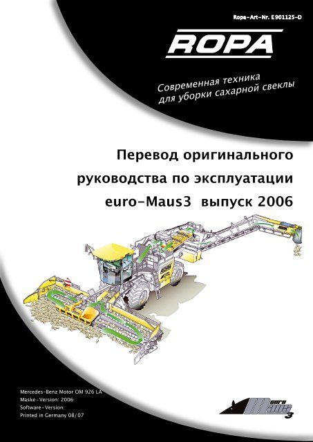
Mercedes-Benz Motor OM 926 LA Maske-Version: 2006 Software-Version: Printed in Germany 08/07 Современная техника для уборки сахарной свеклы <strong>Перевод</strong> <strong>оригинального</strong> <strong>руководства</strong> <strong>по</strong> эксплуатации euro-Maus3 выпуск 2006
- Page 2 and 3: Impressum Alle Rechte vorbehalten
- Page 5 and 6: Содержание 5 Содерж
- Page 7 and 8: 7 Содержание 6.3.5 Экс
- Page 9 and 10: 9 Содержание 6.20 Эле
- Page 11: 11 Содержание 8.6.3 Ко
- Page 15 and 16: 15 0 Предварительное
- Page 17 and 18: 17 0 Предварительное
- Page 19: 19 1 Безопасность Гл
- Page 22 and 23: 1 Безопасность Глав
- Page 24 and 25: 1 Безопасность Глав
- Page 26 and 27: 1 Безопасность 355080 (
- Page 28 and 29: 1 Безопасность Глав
- Page 30 and 31: 1 Безопасность Глав
- Page 32 and 33: 1 Безопасность Глав
- Page 35 and 36: 2 Движение по дорог
- Page 37: 37 2 Движение по доро
- Page 41 and 42: 3 Изображение и тех
- Page 43 and 44: 3.2 Технические данн
- Page 45 and 46: 3 Изображение и тех
- Page 47 and 48: 3 Изображение и тех
- Page 49: 49 4 Общее описание Г
- Page 53:
5 Элементы управлен
- Page 56 and 57:
5 Элементы управлен
- Page 58 and 59:
5 Элементы управлен
- Page 60 and 61:
5 Элементы управлен
- Page 62 and 63:
5 Элементы управлен
- Page 64 and 65:
5 Элементы управлен
- Page 66 and 67:
5 Элементы управлен
- Page 68 and 69:
5 Элементы управлен
- Page 70 and 71:
5 Элементы управлен
- Page 72 and 73:
5 Элементы управлен
- Page 74 and 75:
5 Элементы управлен
- Page 76 and 77:
5 Элементы управлен
- Page 79:
79 6 Эксплуатация Гл
- Page 82 and 83:
6 Эксплуатация Глав
- Page 84 and 85:
6 Эксплуатация Глав
- Page 86 and 87:
6 Эксплуатация Глав
- Page 88 and 89:
6 Эксплуатация Глав
- Page 90 and 91:
6 Эксплуатация Глав
- Page 92 and 93:
6 Эксплуатация Глав
- Page 94 and 95:
6 Эксплуатация Глав
- Page 96 and 97:
6 Эксплуатация Указ
- Page 98 and 99:
6 Эксплуатация Глав
- Page 100 and 101:
6 Эксплуатация Глав
- Page 102 and 103:
6 Эксплуатация Глав
- Page 104 and 105:
6 Эксплуатация Глав
- Page 106 and 107:
6 Эксплуатация Глав
- Page 108 and 109:
6 Эксплуатация Глав
- Page 110 and 111:
6 Эксплуатация Глав
- Page 112 and 113:
6 Эксплуатация Глав
- Page 114 and 115:
6 Эксплуатация Глав
- Page 116 and 117:
6 Эксплуатация Глав
- Page 118 and 119:
6 Эксплуатация 12 Гл
- Page 120 and 121:
6 Эксплуатация Глав
- Page 122 and 123:
6 Эксплуатация Глав
- Page 124 and 125:
6 Эксплуатация Глав
- Page 126 and 127:
6 Эксплуатация Глав
- Page 128 and 129:
6 Эксплуатация Глав
- Page 130 and 131:
6 Эксплуатация Глав
- Page 132 and 133:
6 Эксплуатация Глав
- Page 134 and 135:
6 Эксплуатация Глав
- Page 136 and 137:
6 Эксплуатация Глав
- Page 138 and 139:
6 Эксплуатация Глав
- Page 140 and 141:
6 Эксплуатация Глав
- Page 142 and 143:
6 Эксплуатация Глав
- Page 144 and 145:
6 Эксплуатация Глав
- Page 146 and 147:
6 Эксплуатация Глав
- Page 148 and 149:
6 Эксплуатация Глав
- Page 150 and 151:
6 Эксплуатация Глав
- Page 152 and 153:
6 Эксплуатация 1 Гла
- Page 154 and 155:
6 Эксплуатация Глав
- Page 156 and 157:
6 Эксплуатация Глав
- Page 158 and 159:
6 Эксплуатация Глав
- Page 160 and 161:
6 Эксплуатация Глав
- Page 162 and 163:
6 Эксплуатация Глав
- Page 164 and 165:
6 Эксплуатация Глав
- Page 166 and 167:
6 Эксплуатация Глав
- Page 168 and 169:
6 Эксплуатация Глав
- Page 170 and 171:
6 Эксплуатация Глав
- Page 172 and 173:
6 Эксплуатация Глав
- Page 174 and 175:
6 Эксплуатация Глав
- Page 176 and 177:
6 Эксплуатация Глав
- Page 178 and 179:
6 Эксплуатация Глав
- Page 181:
181 7 Техобслуживани
- Page 184 and 185:
7 Техобслуживание и
- Page 186 and 187:
Vor dem Wiedereinbau muss das gerei
- Page 188 and 189:
7 Техобслуживание и
- Page 190 and 191:
7 Техобслуживание и
- Page 192 and 193:
7 Техобслуживание и
- Page 194 and 195:
7 Техобслуживание и
- Page 196 and 197:
7 Техобслуживание и
- Page 198 and 199:
7 Техобслуживание и
- Page 200 and 201:
7 Техобслуживание и
- Page 202 and 203:
7 Техобслуживание и
- Page 204 and 205:
7 Техобслуживание и
- Page 206 and 207:
7 Техобслуживание и
- Page 208 and 209:
7 Техобслуживание и
- Page 210 and 211:
7 Техобслуживание и
- Page 212 and 213:
7 Техобслуживание и
- Page 214 and 215:
7 Техобслуживание и
- Page 216 and 217:
7 Техобслуживание и
- Page 218 and 219:
7 Техобслуживание и
- Page 220 and 221:
7 Техобслуживание и
- Page 222 and 223:
7 Техобслуживание и
- Page 224 and 225:
7 Техобслуживание и
- Page 226 and 227:
7 Техобслуживание и
- Page 228 and 229:
7 Техобслуживание и
- Page 230 and 231:
7 Техобслуживание и
- Page 232 and 233:
7 Техобслуживание и
- Page 234 and 235:
7 Техобслуживание и
- Page 236 and 237:
7 Техобслуживание и
- Page 238 and 239:
7 Техобслуживание и
- Page 240 and 241:
7 Техобслуживание и
- Page 242 and 243:
7 Техобслуживание и
- Page 244 and 245:
7 Техобслуживание и
- Page 246 and 247:
7 Техобслуживание и
- Page 249:
249 8 Неисправности и
- Page 252 and 253:
8 Неисправности и и
- Page 254 and 255:
8 Неисправности и и
- Page 256 and 257:
8 Неисправности и и
- Page 258 and 259:
8 Неисправности и и
- Page 260 and 261:
8 Неисправности и и
- Page 262 and 263:
8 Неисправности и и
- Page 264 and 265:
8 Неисправности и и
- Page 266 and 267:
8 Неисправности и и
- Page 268 and 269:
8 Неисправности и и
- Page 270 and 271:
8 Неисправности и и
- Page 272 and 273:
8 Неисправности и и
- Page 274 and 275:
8 Неисправности и и
- Page 276 and 277:
8 Неисправности и и
- Page 278 and 279:
8 Неисправности и и
- Page 280 and 281:
8 Неисправности и и
- Page 282 and 283:
8 Неисправности и и
- Page 284 and 285:
8 Неисправности и и
- Page 286 and 287:
8 Неисправности и и
- Page 289:
9 Списки и Таблицы/П
- Page 292 and 293:
9 Списки и Таблицы/П
- Page 294 and 295:
9 Списки и Таблицы/П
- Page 296 and 297:
9 Списки и Таблицы/П
- Page 298 and 299:
9 Списки и Таблицы/П
- Page 300 and 301:
9 Списки и Таблицы/П
- Page 302 and 303:
9 Списки и Таблицы/П
- Page 304 and 305:
9 Списки и Таблицы/П
- Page 306 and 307:
BB00.40-P-0228-05A 9 Списки
- Page 308 and 309:
9 Списки и Таблицы/П
- Page 310 and 311:
9 Списки и Таблицы/П
- Page 312 and 313:
9 Списки и Таблицы/П
- Page 314 and 315:
9 Списки и Таблицы/П
- Page 316 and 317:
9 Списки и Таблицы/П
- Page 318 and 319:
9 Списки и Таблицы/П
- Page 321:
321 Индекс Индекс Ин
- Page 324 and 325:
Индекс Индекс В Вал
- Page 326 and 327:
Индекс Индекс З Зад
- Page 328 and 329:
Индекс Индекс Мног
- Page 330 and 331:
Индекс Индекс Пере
- Page 332 and 333:
Индекс Индекс Расш
- Page 334 and 335:
Индекс Индекс Торм
Delete template?
Are you sure you want to delete your template?
Save as template?
Euro-Maus — это самоходная машина для очистки и погрузки сахарной свеклы, погрузка осуществляется с бурта, находящегося на краю поля, в кузов грузовика, стоящего на дороге.
Технические данные euro-MAUS 3:
| Тип машины: | e-M3 |
| Начиная с серии: | 2006 |
| Тип двигателя Daimler Chrysler: | Mercedes Benz OM926LA E3A/2 |
| Сертификат: | E 3A/2 |
| Уровень выхлопа: | Euromot 3a |
| Норма выхлопа: | 97 / 68 / EG Ступень 3a |
| Мощность: | 220 кВт при 2200 min-1 |
| Макс. крутящий момент: | 1200 Nm / 1300 — 1600 min-1 |
| Рабочее число оборотов: | 2200 min-1 |
| Тип привода: | Дизельный двигатель 4-тактный, с непосредственным впрыском |
| Объём двигателя: | 7.201 cm³ |
| Привод движения: | Бесступенчатый гидростатический с тремя рабочими режимами |
|
Режим „Черепаха I“: Режим „Заяц I“: „Заяц II“: |
0 — 0,7 км/ч 0 — 10,3 км/ч 0 — 20 км/ч (или. 25 км/ч) |
| Два моста с механическим приводом, с блокировкой дифференциала и с подвижной в вертикальной плоскости задней осью. Одна дополнительная ось (серийно для ФРГ; по заказу для всех других стран) | |
| Вес в не заправленном состоянии в зависимости от варианта оснащения: | 24.700 кг до 26.550 кг |
| Допустимый общий вес | смотреть табличку данных на комбайне |
| Ёмкость топливного бака: | 1340 л |
| Расход топлива: | 0,12 — 0,20л /на погруженную тонну, в среднем за сезон макс. 20 л/ч |
| Шины впереди и сзади: | 710/75 R34 178A8 |
| Дополнительная ось (доп. оборудование): | 235/75 R17,5 |
| Производительность погрузки: | в среднем 200 т/ч |
| Электрогенераторы: | 2 x 100 A |
| Бортовое напряжение: | 24 В |
| Ёмкость аккумуляторов: | 2 x 143 Aч |
| Длина (в транспортном положении): | 13350 mm |
| Ширина: | 3000 mm |
| Высота (в транспортном положении): | 4000 mm |
| Шумность (при проезде): | 88,7dB (A) |
| Теплоноситель в кондиционере: | R134a |
| Заполнение теплоносителем около: | 1,7 кг |
ФУНКЦИОНАЛЬНОСТЬ И ПРАКТИЧНОСТЬ
Погрузчик euro-Maus 3 осуществляет очистку и погрузку с производительностью до 550 т/ч.
МАКСИМАЛЬНАЯ МАНЕВРЕННОСТЬ — БЫСТРАЯ ПЕРЕУСТАНОВКА
Движение по дорогам
По дороге euro-Maus передвигается в автомотивном режиме, т.е. требуемая скорость движения всегда выбирается на максимально возможно низком числе оборотов двигателя при минимальном расходе топлива. При нажатии педали акселератора выполняется совместное регулирование привода движения и числа оборотов двигателя. Электро-пневматическое переключение передач освобождает водителя от некоторых обязанностей и надежно предотвращает включение неправильной передачи. Предельная скорость 20 км/ч (опция 25 км/ч) достигается уже при экономных 1250 об./мин. (или 1550 об./мин.).


Быстрая переустановка
Без выхода водителя из кабины можно привести «euro-MAUS» из транспортного положения в рабочее положение всего за 2 минуты. Это позволяет реализовать быстрый и удобный переход между буртами. Небольшое время простоя обеспечивает максимальную производительность при погрузке корнеплодов.
КОМФОРТ КАБИНЫ

В специально разработанной фирмой ROPA кабине объединены современный дизайн, отличный обзор и превосходная шумоизоляция, которые создают физиологически полноценное и очень удобное рабочее место. Равномерно изогнутое лобовое стекло обеспечивает превосходный обзор. Дополнительно низко посаженный край лобового стекла обеспечивает водителю эргономично правильное положение и беспрепятственный вид всей ширины приема.
Полностью тонированные стекла, регулируемая рулевая колонка, пневматически-подпружиненное комфортное сидение, автомагнитола с МР3 проигрывателем с аудиосистемой, видеонаблюдение за глубиной хода подборщика, а также пневматически складываемые боковые зеркала с обогревом создают рабочее место, которое полностью соответствует любым потребностям. Создавая абсолютный комфорт, в качестве опции мы предлагаем автономное отопление кабины, которое подогревает также гидравлический бак и серийный климат-контроль с бесступенчатой регулировкой вентилятора.

Место водителя
Поворачиваемое примерно на 250° поворотное сиденье, включая встроенную консоль управления и новый цветной терминал. Таким образом, водитель всегда имеет перед собой всю информацию о состоянии подборщика и приемной части в нужном ему положении сиденья. Консоль управления и сиденье водителя с пневматической подвеской регулируются индивидуально относительно друг друга, чтобы водитель мог выбрать наиболее удобное положение осанки, чтобы сохранить свое здоровье и производительность труда. Поворотное сиденье можно зафиксировать в любом положении нажатием кнопки, чтобы также при погрузке на боковом склоне положение водителя на сиденье не вызывало бы дополнительных физических усилий.

Управление
Правым джойстиком осуществляется управление всеми важными функциями погрузки, регулирование глубины хода, есть возможность отдельного включения/выключения любых узлов привода и даже их резервирования. Так сказать, вся машина у водителя под одной рукой, а другая рука свободна для радио или телефона. Независимо от того, осуществляется отгрузка на левую или на правую сторону, благодаря реверсированию направления отгрузки джойстиком управлять перегрузчиком удобно всегда.
СИСТЕМА ПРИЕМА
8,7 М ДЛЯ ГИБКОЙ НАСТРОЙКИ ОЧИСТКИ
Бурт корнеплодов раcпределяется уникальной ROPA приемной частью шириной 8,70 м равномерно налево и направо. Делитель бурта, имеющий постоянный эксцентриковый привод, разрыхляет бурт и обеспечивает равномерное разделение потока корнеплодов. Результатом этого решения является низкий расход энергии при продвижении машины вглубь бурта. Свободное пространство под приемным транспортером и равномерное распределение отчищенной грязи под всей шириной приемного стола являются значительными преимуществами этой концепции подбора свеклы.
Бурт корнеплодов распределяется уникальной ROPA приемной частью шириной 8,70 м равномерно налево и направо. Делитель бурта, имеющий постоянный эксцентриковый привод, разрыхляет бурт и обеспечивает равномерное разделение потока корнеплодов. Результатом этого решения является низкий расход энергии при продвижении машины вглубь бурта. Свободное пространство под приемным транспортером и равномерное распределение отчищенной грязи под всей шириной приемного стола являются значительными преимуществами этой концепции подбора свеклы.

Пальцевые вальцы работают в почве на глубине 7 см под буртом. Таким образом сахарная свекла очень бережно поднимается снизу и подается вверх через транспортирующие на очищающие вальцы. Они обеспечивают одновременно очистку и равномерную подачу корнеплодов. При помощи полиуретановых пальцев происходит очистка корнеплодов с левого и правого краев приемного стола и одновременно подача свеклы к 4-м затягивающим вальцам, движущимся навстречу друг другу. Эффект затягивания обеспечивает последующую интенсивную очистку от остатков почвы, ботвы, головок свеклы, а также от травы и сорняков и при этом не повреждая свеклу. Также измельченная солома, используемая для укрывания буртов, очищается затягивающими вальцами и распределяется под всей шириной приемного стола.
Бережная подборка, интенсивная очистка, равномерное распределение очищенной грязи и низкие расходы на техобслуживание euro-MAUS являются базой для высокого качества свеклы и минимальных расходов при выращивании свеклы и ее транспортировке, а также упрощают последующую обработку почвы под буртом.
ДООЧИСТКА

Максимальная производительность перегрузки — бережная доочистка
Приемный транспортер ROPA, имеющий не повреждающие корнеплоды, высокопрочные и мягкие полиуретановые захваты, бережно и быстро транспортирует свеклу под кабиной к следующему элементу очистки. Поток свеклы хорошо и удобно заметен с поворотного сидения в кабине. При выключении приемного транспортера подбор и подача выключаются автоматически.
На пути следования от приемного транспортера до перегрузчика можно выбрать очистку транспортером или очистку затягивающими вальцами. Приемный транспортер шириной 90 см обеспечивает хороший результат очистки благодаря бесступенчатой регулировке числа оборотов с терминала для разных типов почв.

Очистка транспортером
Просеивающий транспортер шириной 90 см дает хороший эффект очистки на легких и средних почвах.

Очистка затягивающими вальцами
Эффективная очистка также для очень тяжелых почв и при сильной загрязненности сорняками.
Небольшой износ благодаря расположенным в форме желоба вальцам с 3 шовной наплавкой.
ДВИГАТЕЛЬ
Рядный двигатель Mercedes Benz OM 926 LA мощностью 220 кВт/299 л.с. установлен на прочной рамной конструкции. Его максимальный крутящий момент 1200 Нм достигается в диапазоне частоты вращения 1300-1600 об/мин. Благодаря новой концепции привода экономичный турбированный двигатель с интеркулером, по сравнению с предшествующей моделью, позволяет снизить на 12% частоту вращения двигателя при отгрузке. Индикатор загрязнения топливного фильтра заблаговременно предупредит о загрязнении до появления потери мощности. Силовой агрегат в звукоизолированном моторном отсеке хорошо просматривается и доступен для контроля или для работ по техническому обслуживанию без проблем. Плоскоременная передача с автоматическим натяжным устройством обеспечивает передачу усилия на оба генератора, помпу и компрессор климат-контроля. Кожух аккумуляторного отсека можно открыть и использовать в качестве рабочей площадки.

Эффективная гидравлическая система обеспечивает снижение числа оборотов
Для преобразования усилий euro-Maus 3 оснащен очень высокопроизводительной гидравлической установкой. Питание всей рабочей гидравлики осуществляется от нового гидронасоса Load Sensing, который обеспечивает высокую гидравлическую мощность при небольшом числе оборотов двигателя. Большой комбинированный обратный фильтр очищает все стекающее обратно масло. Дополнительно фильтр высокого давления полностью защищает рабочую гидравлику от загрязнений. Новый редуктор привода гидронасосов с циркуляционной смазочной системой и переключаемой под нагрузкой муфтой сцепления для подключения всех рабочих приводов, позволяет легко запускать дизельный двигатель также при очень низких температурах. С целью контроля за давлением масла для смазки редуктора была установлена турбина для измерения количества масла. Фильтр грубой очистки и фильтр тонкой очистки в замкнутом масляном контуре дополнительно обеспечивают оптимальную надежность редуктора привода гидронасосов.
-
Contents
-
Table of Contents
-
Bookmarks
Quick Links
Original Operating Manual
Original Operating Manual
E901165-GB
E901165-GB
Translation of the
Translation of the
Maus 5
Maus 5
Edition 1
Edition 1
Software version: 16M5005
Software version: 16M5005
Printed in Germany: 06/2016
Printed in Germany: 06/2016
Related Manuals for ROPA Maus 5
Summary of Contents for ROPA Maus 5
-
Page 1
Translation of the Translation of the Original Operating Manual Original Operating Manual Maus 5 Maus 5 Edition 1 Edition 1 Software version: 16M5005 Software version: 16M5005 Printed in Germany: 06/2016 Printed in Germany: 06/2016 E901165-GB E901165-GB… -
Page 2
– with the express approval of ROPA GmbH. Any type of reproduction, distri- bution or storage on data medium in any form and of any type not authorized by ROPA GmbH forms a violation of current domestic and international copyright law and will be judicially prosecuted. -
Page 3
Contents Contents 3 / 476… -
Page 4
Contents 4 / 476… -
Page 5: Table Of Contents
Contents Preface…………….. 13 Name plate and important data……………17 Serial number of diesel engine…………… 18 Declaration of Conformity……………. 19 Safety…………….21 General………………..23 Obligations of the entrepreneur……………23 General symbols and instructions…………23 2.3.1 Safety signs………………… 24 Proper use………………..25 2.4.1 Foreseeable misuse…………….25 Hazard zone………………..
-
Page 6
Contents Steering column………………64 5.4.1 Steering column switch…………….64 Driver’s seat…………………65 5.5.1 Rotate driver’s seat………………71 Operating components on the floor of the driver‘s cabin……72 Operating console R-Concept…………..73 5.7.1 Colour terminal R-Touch…………….74 5.7.1.1 Positioning R-Touch……………..75 5.7.2 R-Select………………..76 5.7.3 R-Direct………………..79 5.7.4 Keypad I………………..80 5.7.5… -
Page 7
Contents 6.6.3 Engine speed adjustment…………..144 6.6.4 Power reduction SCR system…………… 146 6.6.4.1 Power reduction AdBlue filling level…………147 6.6.4.2 Power reduction AdBlue quality/system error……..148 6.6.4.3 Power reduction process……………149 6.6.5 Modifications respectively additions to the engine operating manual from Mercedes-Benz………………149 Operating modes «Turtle»… -
Page 8
Contents 6.13.8.1 Sieve conveyor cleaner (option)…………224 6.13.8.1.1 Fast speed sieve conveyor cleaning…………. 225 6.13.8.2 8-set pinch roller cleaning (option)…………226 6.13.8.3 Beet brake (only for 8-set pinch roller cleaner)……..227 6.13.9 Infeed conveyor (drive C in the drawing)……….228 6.13.9.1 Infeed conveyor fast motion………….. -
Page 9
Contents 6.22.1.2 Icons…………………..286 6.22.1.3 Keys and controls………………287 6.22.2 Operation of park heating…………..287 6.22.2.1 Switch on heater with immediate start button……..287 6.22.2.2 Switch on heater with the Heater menu……….288 6.22.2.3 Adjust remaining runtime during operation……….. 288 6.22.2.4 Switch off heater………………289 6.22.2.5 Setting and activating timer…………..289 6.22.2.6… -
Page 10
Contents Mechanical drive for steering axles…………339 7.4.1 Cardan shafts from gearbox to the steering axles…….. 339 7.4.2 Maintenance knuckle joints of the axles……….340 Manual transmission (4-gear)…………..340 Axles…………………. 343 7.6.1 Planetary gears (applies to both axles)……….343 7.6.2 Differential gears on front and rear axle……….345 Pneumatic system…………….. -
Page 11
Software updates……………….464 9.11 Confirmation about instructions given to the driver……. 465 9.12 Safety instructions…………….. 466 9.13 Layout chart for a beet pile…………..467 9.14 Notes for beet harvesting…………..468 9.14.1 Practical tips………………468 9.15 ROPA Handover confirmation…………… 469 11 / 476… -
Page 12
Contents Index…………….471 12 / 476… -
Page 13: Preface
Preface Preface 13 / 476…
-
Page 14
Preface 14 / 476… -
Page 15
They conform to the high ROPA standards for safety and reliability. We would like to point out that parts and accessories not approved by ROPA may not be used on ROPA machines, otherwise the safety and operability of the machine may be impaired. -
Page 16
We expressly point out that any damage caused by the fact that this operating man- ual is not or not completely followed is not covered by the statutory warranty of ROPA. Even though this operating manual is comprehensive, in your own interest you should completely and carefully read it and slowly familiarize yourself with the machine using this operating manual. -
Page 17: Name Plate And Important Data
Preface Name plate and important data Name plate and important data The name plate (2) of the machine is located on the right side of the vehicle, on the vehicle frame near the front wheel behind the factory number (1). Please enter the data of your machine in the following image of the name plate.
-
Page 18: Serial Number Of Diesel Engine
Preface Serial number of diesel engine Serial number of diesel engine The serial number of the engine (1) is located on the engine block near the V-belt pul- ley of the crankshaft. 18 / 476…
-
Page 19: Declaration Of Conformity
The Declaration of Conformity belongs to separately provided documents and is handed over on the delivery of the machine. The CE marking of the machine is a constituent part of the nameplate. ROPA Maus5 from 8*1151 from 2014 1st September 2015…
-
Page 20
Safety 20 / 476… -
Page 21: Safety
Safety Safety 21 / 476…
-
Page 22
Safety 22 / 476… -
Page 23: General
Safety General symbols and instructions General The machine has been manufactured according to the current state of technology and tested for safety. The machine is CE compliant and therefore conforms to the respective European reg- ulations for free movement of goods within the European Union respectively the Euro- pean economic region.
-
Page 24: Safety Signs
Safety General symbols and instructions CAUTION This signal word warns you of a possibly dangerous situation which may lead to seri- ous injury or to death and damage to the machine or other serious property dam- age. Non-observance of these instructions may lead to loss of warranty. This hazard may always occur if the operating or working instructions are not or only imprecisely observed.
-
Page 25: Proper Use
Safety Proper use Warning against explosion hazard, battery area This warning symbol stands for activities during which the hazards of corrosive liquid and gases exist. Warning against falling hazard This warning symbol stands for activities during which the hazards of falling with possi- ble deadly consequences exist.
-
Page 26: Hazard Zone
Safety Hazard zone Hazard zone Nobody may stay in the hazard zone during operation of the machine. The opera- tor must immediately shut down the machine in case of any threatening hazard and request the people concerned to leave the hazard zone immediately. He may only restart the machine when no people are located in the hazard zone anymore.
-
Page 27
The meaning of each individual pictograph is explained below. In addition, a six-fig- ure number is given for each pictograph. This is the ROPA order number. Stating this number, you may reorder the respective pictograph from ROPA. The number stated in brackets is printed on the respective sticker. -
Page 28: Safety Stickers On The Machine
Safety Safety stickers on the machine Safety stickers on the machine Art.-Nr.: 355069 Art.-Nr.: 355067 Art.-Nr.: 355065 Art.-Nr.: 355078 Art.-Nr.: 355072 Art.-Nr.: 355077 Art.-Nr.: 355074 Art.-Nr.: 355063 Art.-Nr.: 355073 Art.-Nr.: 355064 Art.-Nr.: 355079 Art.-Nr.: 355079 Art.-Nr.: 355069 Art.-Nr.: 355074 Art.-Nr.: 355077 Art.-Nr.: 355063 Art.-Nr.: 355072 Art.-Nr.: 355074…
-
Page 29
Safety Safety stickers on the machine 355071 (1) 355079 (04) Before starting up, read the operat- Hazard under loads. Never stay ing manual respectively the main- under this part. tenance manual and observe all remarks on safety. 355077 (25) 355063 (33) Hazard that body parts can be Hazard from parts being flung away pulled in. -
Page 30: Safety And Health Protection
Safety Safety and health protection 355074 (06) 355078 (11) Hazard of swinging Hazard of lowering machine parts. Never machine parts! Staying stay in swivelling area. in the hazard zone is only admissible when the safety lock for the lifting cylinder is engaged. 355072 (15) 355065 (37) Hazard from rotating…
-
Page 31: Requirements For Operating And Maintenance Personnel
All maintenance work which is not specifically the responsibility of the operator may only be carried out by instructed or trained maintenance personnel. Some activities may only be performed by people expressly authorized by ROPA for these activities. In case of doubt, ask the manufacturer whether you may perform a specific activity yourself without any hazard.
-
Page 32: Handling And Process Materials
Safety Hazards caused by mechanical influences 2.11 Handling and process materials When handling process materials the appropriate protective clothing must always be worn to prevent or reduce skin contact with these materials. Defective, dismantled parts shall be sorted according to material type and routed to the proper recycling channel.
-
Page 33: Hazards Caused By Electricity
Safety Hazards caused by process materials 2.14 Hazards caused by electricity DANGER Life hazard due to electric voltage. Cables and components are live, there is a danger of injury with deadly conse- quences. Clamping points are under voltage also after shut-off. –…
-
Page 34: Hazards Caused By Noise
Safety Hazards caused by the hydraulic system ADVICE Hazard of damage to the environment by leaking fuel or oil! Hazard of pollution of ground or water bodies. Prevention: – Always carefully close containers containing fuel or oil. – Dispose empty containers in accordance with regulations and in an environmen- tally compatible manner.
-
Page 35: Hazards Caused By Pneumatic System
Safety Personal protective equipment 2.18 Hazards caused by pneumatic system In case of damage to the pneumatic system, the raised warning signs on the pile pickup may suddenly come down and cause severe injury to people located in this area. When working on the pneumatic system there is a risk that compressed air escapes abruptly and causes injuries.
-
Page 36: Leakage
Safety Prohibition of unauthorized modifications and alterations 2.21 Leakage The following measures shall be taken in case of leakage: – Switch off the effective component and set it pressure-free if possible. – Place a suitable container underneath. – Exchange a component/sealing. –…
-
Page 37: General Safety Instructions For The Park Heating System
Safety Safety and protective equipment 2.24 General safety instructions for the park heating system The heating appliance may not be operated in enclosed rooms, not even under timer control or «Telestart» (e.g. garage or workshops without exhaust-gas extrac- tion). Due to the explosion hazard, the heating system must be switched off at gas sta- tions and fuel dispensing systems.
-
Page 38: Emergency Exit
Safety Emergency exit Overview Rotating beacon front Battery emergency stop switch Safety rail at the ladder Protective rubber at recleaner Protection bar at truck conveyor Emergency stop switch in the operating console Loud-speaker public address system 2.26 Emergency exit Depending on the design, the machine is not equipped with a dedicated emergency exit.
-
Page 39: General View And Specifications
General View and Specifications General View and Specifications 39 / 476…
-
Page 40
General View and Specifications 40 / 476… -
Page 41: General View
General View and Specifications General view General view This overview is intended to familiarize you with the most important components of your machine. Central electrics cabinet Rear platform wall Air filter Compensation tank for coolant Intake grid for cooler Engine compartment Hydraulic oil tank Storage compartment for tools Battery case…
-
Page 42
General View and Specifications General view (18) Underrun protective device (19) Fuel tank (20) Counterweight arm (21) Articulation of the truck conveyor (22) Truck conveyor (23) Swivel support for truck conveyor (24) Recleaning (25) Energy ducting chain (26) Rear axle (27) Pickup side section left (28) -
Page 43
General View and Specifications General view (29) Swivel arm (30) Rotary drive for truck conveyor (31) Rotary drive for swivel arm (32) Swivel support for truck conveyor (33) Swivel arm lock (34) Cylinder axle support (35) Storage compartment in the engine compartment (36) Counterweight arm lock 43 / 476… -
Page 44
General View and Specifications General view (37) Control unit operating hydraulics II (38) Fire extinguisher (39) Grease bucket (40) Tank for windscreen washer system (41) Control unit operating hydraulics I (42) AdBlue® tank (43) Water tank (optional) (44) Exhaust system with SCR catalytic converter 44 / 476… -
Page 45
General View and Specifications General view (45) Fold plates (46) Clearing shield (47) Pinch roller 4 (48) Pinch roller 3 (49) Pinch roller 2 (50) Pinch roller 1 (51) Conveyor roller 3 (52) Conveyor roller 2 (53) Conveyor roller 1 (54) Cleaning roller (55) -
Page 46
General View and Specifications General view Machine ready for driving on roads 46 / 476… -
Page 47: Technical Data
TIER 4 final Capacity: 260 kW Max. torque: 1400 Nm/1200-1600 min Rated speed (engine manufacturer): 2400 min Rated speed (ROPA): 2200 min Maximum rotational speed with machine drive 1975 min switched on: Engine type: Diesel engine 4-stroke, direct fuel injection Displacement: 7698 cm³…
-
Page 48
General View and Specifications Technical data Tires front axle: 710/75 R34 Michelin MegaXBib (178A8) 800/70R32 Michelin CEREXBIB (182A8) Tires rear axle: 710/75 R34 Michelin MegaXBib (178A8) 800/70R32 Michelin CEREXBIB (182A8) Tires additional axles: 235/75 R17.5 Generator: 150 A System voltage: 24 V Battery capacity: 2 x 170 Ah… -
Page 49: Tyre Pressure
General View and Specifications Tyre pressure Tyre pressure Tyre pressure Tires type min. Recommendation max. Front axle 710/75 R34 TL 178A8 800/70 R32 TL 182A8 Rear axle 710/75 R34 TL 178A8 800/70 R32 TL 182A8 Others min. Recommendation max. additional axle 235/75 R17.5 49 / 476…
-
Page 50: Transport Draft For Low-Loader Transport
General View and Specifications Transport draft for low-loader transport Transport draft for low-loader transport All data in mm. 50 / 476…
-
Page 51: Lashing Eyes For Transport By Low-Loader/Ship
General View and Specifications Lashing eyes for transport by low-loader/ship Lashing eyes for transport by low-loader/ship The front axle is equipped with eyes, located on the right and left side, for clamping it down in ground direction. The rear axle support is also equipped with eyes located on the right and left side for clamping the axle down towards the ground.
-
Page 52
General View and Specifications Lashing eyes for transport by low-loader/ship Lashing point behind the front axle, left side Lashing point at the rear axle support Loading onto ship; photo of an earlier model The machine has no mount points on which it can be lifted. For hoisting it into a ship for example, special, approved and TÜV-approved lifting devices are necessary. -
Page 53: General Description
General Description General Description 53 / 476…
-
Page 54
General Description 54 / 476… -
Page 55: Function
General Description Function Function This is a self-propelled working machine for picking up, cleaning and loading of sugar beet in piles at the side of the field. Picking up of sugar beet is performed using a roller system. The first roller, the pickup roller, works several centimetres into the ground, picks up the sugar beet and lifts it over a cleaning roller onto three conveyor rollers.
-
Page 56: Scope Of Delivery
General Description Scope of delivery Scope of delivery The scope of delivery of the machine includes a fire extinguisher, a first-aid kit, two wheel chocks and a tool set with small parts package. The first-aid kit is located in the driver’s cabin, the fire extinguisher is located on the central electrical system cabinet.
-
Page 57: Operating Components
Operating Components Operating Components 57 / 476…
-
Page 58
Operating Components 58 / 476… -
Page 59: Ladders
Operating Components Ladders Ladders DANGER – Nobody may stay on the platform in front of the driver‘s cabin and in the driver’s cabin when the machine works. – Ascend ladders and machine only when the machine stands still! Use of ladders see page 31 5.1.1 Ladder driver’s cabin…
-
Page 60: Auxiliary Steps On The Fuel Tank
Operating Components Ladders 5.1.2 Auxiliary steps on the fuel tank Auxiliary steps on the fuel tank in road position respectively folded for refueling Guard rail Locking lever Auxiliary steps WARNUNG Falling hazard! The auxiliary steps on the fuel tank may be used only for refueling the machine and for relubricating via the nipple block.
-
Page 61: Driver’s Cabin Cylinder Support
Operating Components Driver’s cabin cylinder support Driver’s cabin cylinder support The driver’s cabin must not be raised or lowered unless both pickup side sections are folded out and if the driver is sure that there is no obstacle within a height of 5.3 m above the driver’s cabin.
-
Page 62
Operating Components Driver’s cabin cylinder support WARNUNG Risk of very serious injuries – The driver is responsible for ensuring that there is nobody in the area between the safety rail at the boarding steps (2) and the cabin door when lifting or lowering the cabin. -
Page 63: Driver’s Cabin Overview
Operating Components Driver’s cabin overview Driver’s cabin overview Roof console Roof console storage compartment Left joystick Operating console at driver’s seat Joystick with multi-functional handle Roller blind Video monitor Steering column Microphone for public address system 63 / 476…
-
Page 64: Steering Column
Operating Components Steering column Steering column DANGER Hazard of deadly injuries if the steering column is moved while driving. In this case, the machine can go out of control and cause the severest damages. – Therefore, NEVER move the steering column while driving! Clamping screw (1) incline adjustment Loosen the clamping screw (1) and pull or push steering column into the desired posi- tion.
-
Page 65: Driver’s Seat
Operating Components Driver’s seat Main menu Loading settings Main settings Light control Water spray system Window wiper Window wiper Driver’s seat Safety instructions: To prevent damage to the driver’s back, the seat must be adjusted for the driver’s weight before use and before every change of driver. To prevent injury, no objects should be placed within the moving area of the driver’s seat.
-
Page 66
Operating Components Driver’s seat Weight adjustment The seat should be adjusted for the dri- ver’s weight by briefly pulling the actu- ator lever of the automatic weight and height adjuster (arrow) with the vehicle at a standstill and the driver sitting on the seat. -
Page 67
Operating Components Driver’s seat Seat depth adjustment The depth of the seat pan can be indi- vidually adjusted. To adjust the depth of the seat cushion, lift the right handle (see arrow). By moving the seat cushion back- wards or forwards the desired seating position can be reached. -
Page 68
Operating Components Driver’s seat Headrest The headrest can be individually adjusted for height by pulling it upward over the various increments up the end stop. By pushing forward or backward the angle of the headrest can be adjusted individually. To remove the headrest, pull it over the end stop. -
Page 69
Operating Components Driver’s seat Armrest inclination The inclination of the armrest can be modified by turning the adjustment hand wheel (arrow). Backrest adjustment CAUTION Take care with the backrest frame – it may jerk forward and cause injury! – Hold the backrest hand tight before adjusting. The backrest is adjusted using the locking lever (arrow). -
Page 70
Operating Components Driver’s seat Cleaning Dirt can impair the function of the seat. Make sure you keep your seat clean. Upholstery can be quickly and simply removed from the seat frame for easy cleaning or replacement. Avoid soaking of the upholstery when cleaning the upholstered surface. -
Page 71: Rotate Driver’s Seat
Operating Components Driver’s seat 5.5.1 Rotate driver’s seat The rotatable driver’s seat has a pneumatic seat brake. This seat brake is operated using the switch (17) on the left joystick. his enables you to fix the seat in the position most favourable for you.
-
Page 72: Operating Components On The Floor Of The Driver’s Cabin
Operating Components Operating components on the floor of the driver‘s cabin Operating components on the floor of the driver‘s cabin Opener for cleaning flap Foot-switch look forward Foot switch driving direction Brake pedal Drive pedal 72 / 476…
-
Page 73: Operating Console R-Concept
Foldable armrest with storage compartment Switches on operating console (10) Joystick with multi-functional handle (11) Main steering switch (12) Lever height adjustment operating console ADVICE Use only the USB stick supplied by ROPA or a similar stick formatted in FAT 32. 73 / 476…
-
Page 74: Colour Terminal R-Touch
Operating Components Operating console R-Concept Outlets at the front side of the operating console (13) Outlet 24V/8A maximum (14) Outlet 12V/5A maximum 5.7.1 Colour terminal R-Touch With R-Touch (1) different settings can be performed only by touching on the screen. Since it is a capacitive touch screen (PCAP), the screen also reacts to touches with stylus or gloves.
-
Page 75: Positioning R-Touch
Operating Components Operating console R-Concept 5.7.1.1 Positioning R-Touch The R-Touch color terminal has four different ways to change its position in order to operate it optimally. Adjustment of the operation panel (1): Hereby the whole carrier tube can be rotated forward and backward. Fold the operating console backwards, loosen the knurled screw, swing the holding tube to the desired position and tighten the knurled screw.
-
Page 76: R-Select
Operating Components Operating console R-Concept 5.7.2 R-Select The R-Select (2) (BLUE screen and operating panel colour) allows the driver to per- form about 15 different functions without knowing the menu structure. There are no submenus here which require additional knowledge. Generally, there are two possibili- ties to operate the R-Select mode.
-
Page 77
Operating Components Operating console R-Concept Selected air conditioner temperature R-Select mode (e.g. air conditioner temperature is selected) 77 / 476… -
Page 78
Operating Components Operating console R-Concept The following functions are included in R-Select mode: Rpm pickup rollers Raise/lower driver’s cabin Rpm conveyor rollers Counterweight up/down Rpm 4 pinch rollers Counterweight arm lock Rpm infeed conveyor Swivel arm lock Rpm recleaning Rotate recleaner Rpm truck conveyor Set temperature air conditioning in Celsius or Fahrenheit… -
Page 79: R-Direct
Operating Components Operating console R-Concept 5.7.3 R-Direct The R-Direct function area (5) (YELLOW screen and operating panel colour) allows the driver to perform different settings, e.g. access to the main menu with submenus. When touching one of the R-Direct selecting field (5) the R-Touch accepts commands as well as when turning or pressing wheel on the R-Direct (5a).
-
Page 80: Keypad I
Operating Components Operating console R-Concept 5.7.4 Keypad I 355540 (1) Switching operating mode «Turtle/Rabbit»: see page 151 (2) Switching between I/II operating mode In the Gear I operating mode all-wheel drive is automatically switched on. In the Gear II operating mode all-wheel drive is automatically switched off. see page 151 ATTENTION Hazard of severe damage.
-
Page 81: Keypad Ii
Operating Components Operating console R-Concept 5.7.5 Keypad II 355541 (1) STOP diesel engine: Key to stop the engine. (2) START diesel engine: Key to start the engine. (3) Air conditioning system ON/OFF/de-icing: see page 283. (4) Light — working lights: see page 128.
-
Page 82: Switches On Operating Console
Operating Components Operating console R-Concept 5.7.6 Switches on operating console Steer the rear axle right/left (only in «Turtle» operating mode) Emergency stop switch Clearing shield left press forward = unfold press backward = fold Clearing shield right press forward = unfold press backward = fold Parking brake (hand brake) Quick motion switch truck conveyor/infeed conveyor…
-
Page 83: Main Steering Switch
Operating Components Operating console R-Concept 5.7.7 Main steering switch (44) Main steering switch DANGER When the main steering switch is unlocked the driving speed of the machine is limited. – When driving on public roads and paths, the main steering switch must generally be locked.
-
Page 84: Right Joystick With Multi-Functional Handle
Operating Components Operating console R-Concept 5.7.8 Right joystick with multi-functional handle The joystick enables easy control of a multitude of functions of the machine with a single hand without distracting the attention of the operator. For better orientation, a transparent sticker is located on the side window of the driver’s cabin containing the following schematic overview of all functions of the joystick with multifunctional handle.
-
Page 85
Operating Components Operating console R-Concept Joystick movements Press joystick for- = Cruise control ON. ONLY in the operating ward mode «Rabbit». Pull joystick back- = Cruise control OFF ONLY in the operating ward mode «Rabbit». Pull joystick to the = Rear axle steers to the left. ONLY in the oper- left ating mode «Rabbit». -
Page 86: Left Joystick
Operating Components Operating console R-Concept 5.7.9 Left joystick As soon as the left joystick console is folded up, the machine drive and the drive train stop automatically. A detailed description (see Chapter 6.5 page 137) 5.7.10 Ignition lock The ignition lock has three switching positions: Position 0: Shut down engine/ignition off –…
-
Page 87: Switches On Roof Console
Operating Components Switches on roof console Switches on roof console Microphone for public address system Loud-speaker radio Internal lamps on driver’s cabin ceiling LED Radio with Bluetooth (see separate operating manual) Rotating switch to fold in/out the left rearview mirror Rotating switch to fold in/out the right rearview mirror Switch for rotating beacons High beam control (above) / turn signal control (below)
-
Page 88
Operating Components Switches on roof console (16) Timer for park heating (optional) The timer for park heating even functions when the main battery switch is switched off. (17) Switch for LED internal lamps on dirver’s cabin ceiling (18) Storage compartment roof console (76) Battery main switch (see page… -
Page 89: Air Conditioning
Operating Components Air conditioning Air conditioning Air vents in the roof console (view from below) Circulating air grate in the rear wall Rotary open/closed switch circulating air grate Temperature sensor for the air conditioning system As example: air vents in the right A column of the driver’s cabin Air vents in the footwell 89 / 476…
-
Page 90: Engine Compartment
Operating Components Engine compartment 5.10 Engine compartment There is a key (1) in the engine housing, which serves to switch on respectively off engine compartment light. It is active only with the ignition switched on. When the engine housing cover is closed, the engine compartment lights switch off automatically after 15 minutes.
-
Page 91: Outlet On Fuel Tank
Operating Components Outlet on fuel tank Pump cover behind climbing ladder Unlock engine housing maintenance hatch in the infeed conveyor duct 5.11 Outlet on fuel tank Another maximum 24 V/8 A outlet is installed at the rear under the fuel filler nozzle. Outlet on fuel tank 91 / 476…
-
Page 92: Ladder Light
Operating Components Ladder light 5.12 Ladder light The key (1) for switching on the ladder light is in the cutout under the engine hous- ing cover. The ladder lighting also functions when the battery main switch is off. (see page 129) Key for ladder lighting on the outside of the machine 92 / 476…
-
Page 93: Battery Emergency Shutdown
Operating Components Battery emergency shutdown 5.13 Battery emergency shutdown Power supply at the emergency switch turned on (see page 297) ATTENTION Danger of machine damage. If this switch is tilted upward while the ignition is on, it can lead to data loss. It may also seriously damage the exhaust gas after-treatment system (SCR system).
-
Page 94
Operation 94 / 476… -
Page 95: Operation
Operation Operation 95 / 476…
-
Page 96
Operation 96 / 476… -
Page 97: First Startup
Operation First startup This chapter provides all information for operation of the machine. For most work in an agricultural area, the mode of working and the work results are under the influence of many individual and different factors. The scope of this operating manual would be exceeded if we have considered all conceivable situations (ground condition, sugar beet varieties, weather, local land conditions, etc.).
-
Page 98: Safety Regulations For Operation Of The Machine
Operation Safety regulations for operation of the machine Safety regulations for operation of the machine – Before starting work, familiarize yourself with the machine and the operating com- ponents. In case of need, obtain instructions from a person already having suffi- cient experience in handling the machine.
-
Page 99
Operation Safety regulations for operation of the machine DANGER Hazard to life due to rotating rollers! There is a risk of the severest or even deadly injuries for people staying in the haz- ard zone. Especially near the pickup, objects or people may be drawn into rollers by body parts or pieces of clothing. -
Page 100: Working In The Vicinity Of Power Lines
Operation Safety regulations for operation of the machine 6.2.1 Working in the vicinity of power lines DANGER Hazard to life due to electrical current! Due to the dimensions of the machine, the landscape and the construction of power lines, the prescribed safety distance may be violated when working in the vicinity of or under power lines.
-
Page 101: R-Concept
Operation R-Concept R-Concept The R-Touch is the information and command centre of the machine. This is where you monitor the overall machine, obtain information about operating status and perfor- mance data and perform setting for parts of the machine. Before operating, you should indispensably familiarize yourself with the R-Touch and the different warning and status indicators to be able to use the machine safely and effectively.
-
Page 102: Display Areas On The R-Touch
Operation R-Concept 6.3.1.1 Display areas on the R-Touch [A] Display area for warning indicators and hints (see page 122) ADVICE When a warning indicator activates the warning buzzer, you can suppress the sound- ing of the buzzer for a short period clicking on the display area A or pressing the key [B] Display area beet path Relief pressure left Relief pressure mid…
-
Page 103
Operation R-Concept [C] Display area warning thresholds Pickup rollers load Conveyor rollers load 4 pinch rollers load Recleaning load It does not apply to infeed and truck con- veyor drives since these are monitored with rotational speed sensor only and not with pressure sensor. -
Page 104
Operation R-Concept [G] Display and operating panel for R-Select (see page [H] Display actual fuel consumption [I] Indicator for expiration of cooling-off period [J] Fields for status indicators (see page 127) [K] Display and operating panel for R-Direct functional area (see page 108) 104 / 476… -
Page 105
Operation R-Concept [L] Individual display areas Adjust display areas in the top and bottom Select display area in the top or bottom using the R-Direct and switch by pressing on the middle of the wheel. Each press on the R-Direct switches between the possi- ble display areas. -
Page 106
Operation R-Concept (3) Display field: Operating parameters Voltage vehicle power supply Hydraulic oil temperature Hydraulic oil level Cooling water temperature Compressed air system reservoir pressure (10) Pressure traction drive – Arrow counterclockwise: higher pressure forward – Arrow clockwise: higher pressure backward (11) Tank level fuel (12) -
Page 107
Operation R-Concept [M] Open quick selection area Draw the icon from left to right. The quick selection area opens. Draw the icon from right to left beyond the screen edge. The quick selection area is closed. «START» load mode «LOAD» load mode «END»… -
Page 108: Functional Area R-Direct
Operation R-Concept R-Touch cleaning mode This mode allows the glass screen to be cleaned with a soft cloth when R-Touch is activated. Press and hold the switch field (9) for more than 2 seconds to return to nor- mal mode. 6.3.2 Functional area R-Direct R-Direct operating panel…
-
Page 109: Home Key
Operation R-Concept 6.3.2.1 HOME key The key HOME (8) is always available on the R-Touch as well as on the R-Direct oper- ating panel. Press the HOME key once to return to the main screen. 6.3.2.2 Main menu All submenus of the main menu can be selected with the help of R-Touch or R-Direct rotary wheel (5a).
-
Page 110: Menu Loading Settings
Operation R-Concept 6.3.2.2.1 Menu Loading settings Main menu Main menu Loading settings Loading settings Main settings Main settings Light control Light control Water spray system Water spray system Window wiper Window wiper Special functions Special functions System System Main menu Loading settings Pile pickup lift Amount day…
-
Page 111: Menu Main Settings
Operation R-Concept 6.3.2.2.2 Menu Main settings Main menu Main menu Loading settings Loading settings Main settings Main settings Light control Light control Water spray system Water spray system Window wiper Window wiper Special functions Special functions System System Main settings Fuel reserve warning % AdBlue reserve warning % Greasing time (sec)
-
Page 112: Menu Light Control
Operation R-Concept 6.3.2.2.3 Menu Light control Main menu Main menu Loading settings Loading settings Main settings Main settings Light control Light control Water spray system Water spray system Window wiper Window wiper Special functions Special functions System System For detailed information see page 128.
-
Page 113: Menu Window Wiper
Operation R-Concept 6.3.2.2.5 Menu Window wiper Main menu Main menu Loading settings Loading settings Main settings Main settings Light control Light control Water spray system Water spray system Window wiper Window wiper Special functions Special functions System System For detailed information see page 130 113 / 476…
-
Page 114: Menu Special Functions
Operation R-Concept 6.3.2.2.6 Menu Special functions Main menu Main menu Loading settings Loading settings Main settings Main settings Light control Light control Water spray system Water spray system Window wiper Window wiper Special functions Special functions System System Special functions Load mode Loading Traction drive automatic…
-
Page 115: Menu System
Operation R-Concept 6.3.2.2.7 Menu System Main menu Main menu Loading settings Loading settings Main settings Main settings Light control Light control Water spray system Water spray system Window wiper Window wiper Special functions Special functions System System Submenu Date/time date/time 115 / 476…
-
Page 116
Operation R-Concept Submenu Terminal settings settings terminal language display setting standard volume level day/night Night-time display Night-time display 2 brightness/day brightness/night R-Transfer Wi-Fi Key tone In the line «Language» you can set the language of the R-Touch. In the line «Display setting» there is a possibility of switching between standard display and expert mode. -
Page 117: Menu Operating Data
Operation R-Concept Submenu Units units km/h Driving speed Consumption Distance Pressure Consumption/time Weight temperature C° l/km consumption/distance In the “Units” menu you can select various bases of calculation for the physical parameters speed, distance, volume and pressure. Please be careful; if you set, for example, the driving speed at mph instead of km/h, the values on the driving speed display will be completely incomprehensible.
-
Page 118
Operation R-Concept Submenu Season statistics Statistics season Vehicle identification number Operating hours engine Operating hours harvesting Distance Time Consumption consumption/time consumption/distance The „Season statistics“ may only be deleted, if you press the combination of keys 1 and 4 after pressing reset key on the R-Touch keypad. This avoids inadvertent delet- ing. -
Page 119: Menu Service
Operation R-Concept 6.3.2.2.9 Menu Service Main menu Light control Water spray system Window wiper Special functions System Operating data Service Service Version Diagnosis Tuning teach in Master data Change of hardware Change of hardware data service > Submenu Version For the operator, only the submenus «Version» and «Diagnostics» (see chapter «Mal- function and Remedies», see page 387) are of importance in the service menu.
-
Page 120
Operation R-Concept Submenu Data service data service data import service data export service data export service data operating company delete data print data activation software update The «Data service» submenu is required to import, export and to delete databases. Software updates are also implemented using this submenu. Submenu Empty menu service tuning… -
Page 121: Scales
Operation R-Concept 6.3.2.3 Scales Scales Amount day For detailed information from page 256 6.3.2.4 Readjusting warning thresholds Select section Warning thresholds using the R-Direct and confirm the selection by pressing the middle of the wheel. The warning thresholds for the drives of pickup rollers, conveyor rollers, 4-set pinch rollers and recleaning may be adjusted in this functional section.
-
Page 122: Warning And Status Indications On The R-Touch
Operation R-Concept 6.3.3 Warning and status indications on the R-Touch Red warning indicators, which lead to engine stop Engine oil pressure is too low Hydraulic fluid too hot Serious engine problems, immedi- Lubrication pump distributor gear ately switch off engine failed Coolant level too low Hydraulic oil level too low…
-
Page 123
Operation R-Concept Red note indication on electronic problems Rpm signal out of range Error data backup Analogue signal out of range Incorrect machine configuration Line break or short circuit found Communication problem with con- trol device A03 Internal memory fault in EEPROM 123 / 476… -
Page 124
Operation R-Concept Orange warning indicators Pickup rollers overloaded Conveyor rollers overloaded 4 pinch rollers overloaded Infeed conveyor overloaded Recleaner overloaded Truck conveyor overloaded Pickup rollers blocked Conveyor rollers blocked 4 pinch rollers blocked Infeed conveyor blocked Recleaner blocked Truck conveyor blocked Error in Mercedes-Benz engine Battery is not loaded control… -
Page 125
Operation R-Concept Orange hints on operation Please swing out pickup Please close engine housing door Please swing up the fold plates Please close rear platform wall Please release «look forward» Please swing down left joystick foot-switch console Please press «look forward» Please swivel the recleaner into footswitch operating position… -
Page 126
Operation R-Concept While in operating mode «Rabbit», Please change operating mode please shift to 2nd gear Please drive slower Please fill up fuel tank Please drive faster Please fill up AdBlue® Differential lock engaged Please release drive pedal to change the operating mode Operating temperature not Please switch analogue-rocker in reached… -
Page 127
Operation R-Concept Status indicators Oscillating axle support enabled Central lubrication runs Operating mode «Tuttle» is active Operating mode «Rabbit» is active (loading) (road drive) 1st gear is active 2nd gear is active Operating mode «Turtle» selected, Operating mode «Rabbit» gear not engaged selected, gear not engaged 1st gear selected, gear is not 2nd gear selected, gear is not… -
Page 128: Light Control
Operation R-Concept 6.3.4 Light control The lighting in the machine is controlled at R-Touch. The light control menu appears when the key (4) on keypad II is pressed for three seconds. Briefly pressing this key switches the light on or off with the last selected setting. 355541 355541 Window wiper…
-
Page 129: Configure Light Programs
Operation R-Concept 6.3.4.1 Configure light programs The light programs 1-3 can be individually assigned according to your wish. To do this switch on the lights you want to save in a program. Press and hold one of the program keys to save the active lights in a program. Window wiper Light control 6.3.4.2…
-
Page 130: Window Wiper
Operation R-Concept 6.3.5 Window wiper The window wipers on the machine are controlled from the R-Touch. The window wiper menu appears when the key (6) on keypad II is pressed for three seconds. Briefly press this key to switch the wipers on or off with the last selected setting. 355541 355541 ADVICE…
-
Page 131: Configure Window Wiper Program
Operation R-Concept Window wiper Switch selected window wiper on/off Adjustment of pause period for left side window wiper interval Side window wiper left intermittent operation Side window wiper left Adjustment of pause period for front window wiper interval Window wiper program 1 Window wiper program 2 Window wiper program 3 Side window wiper right…
-
Page 132: Right Joystick With Multi-Functional Handle
Operation Right joystick with multi-functional handle Right joystick with multi-functional handle The joystick is the most important operating component of the machine. Here the con- trol of the machine essential functions is ergonomically combined in one operating component. Joystick front side Joystick rear side AUTO Rop Art.
-
Page 133
Operation Right joystick with multi-functional handle Mini joystick (1) FORWARD Lower pickup BACKWARD Raise pickup RIGHT Swivel counterweight arm to the left LEFT Swivel counterweight arm to the right Before swiveling the counterweight arm, it must be unlocked with the R-Select and by pressing the key +. -
Page 134
Operation Right joystick with multi-functional handle Key (6) machine drive PRESS KEY SHORTLY Machine drive On/Off PRESS AND HOLD KEY Reload Key (7) drive pickup rollers and conveyor rollers PRESS KEY SHORTLY On/off PRESS AND HOLD KEY Reverse Key (8) drive 4 pinch rollers PRESS KEY SHORTLY On/off PRESS AND HOLD KEY… -
Page 135
Operation Right joystick with multi-functional handle Joystick movements Only in the operating mode «Rabbit» FORWARD Cruise control ON BACKWARD Cruise control OFF RIGHT Steer rear axle to right LEFT Steer rear axle to left 135 / 476… -
Page 136
Operation Right joystick with multi-functional handle Joystick movements Only in the operating mode «Turtle» Multi-key (11) NOT pressed Only the two rotary drives turn! The rotating direction of the swivel arm always depends on the selected loading direction! Joystick FORWARD Turn swivel arm Joystick BACKWARD Turn swivel arm… -
Page 137: Left Joystick
Operation Left joystick Left joystick As soon as the left joystick console is folded up, the machine drive and the drive train stop automatically. ADVICE All functions can only be executed with the joystick if the seat console is swung down all the way and the machine is operated in operating mode Turtle I or Turtle II.
-
Page 138
Operation Left joystick Mini joystick (15) FORWARD Telescopically extend pile pickup BACKWARD Telescopically retract pile pickup ADVICE These two movements may be reversed as familiar from the euroMaus3 in the «Spe- cial Functions» menu. RIGHT Turn residual beet pickup to the right (same function as using the key (18)) LEFT Turn residual beet pickup to the left (same function as using the key… -
Page 139
Operation Left joystick Only in the operating mode «Rabbit» LEFT Manual diesel engine speed control RIGHT Automotive diesel engine speed control In order to switch over, slide the X-Y key (16) in the required direction and hold it briefly in end position. Only in the operating mode «Turtle»… -
Page 140: Diesel Engine
Operation Diesel engine Diesel engine A summary of the maintenance work required on the engine can be found in Chapter 7 and in the original operating manual and original maintenance documentation from Mercedes-Benz. Notes about measures, that should be taken if any malfunctions occur, can be found in Chapter 8 «Malfunction and Remedies»…
-
Page 141
Operation Diesel engine Engine oil level too low. IMMEDIATELY refill engine oil. (see page 302) Coolant temperature too high. Shut off engine, determine and fix the cause (e.g. clean the radiator). Coolant level too low. Shut off engine and immediately refill coolant. Serious engine problems! Turn off the engine IMMEDIATELY and call the Mercedes Benz customer service. -
Page 142
Operation Diesel engine Main settings Warning-limit fuel tank (%) AdBlue reserve warning % Greasing time (sec) Reverse-automatic rollers Amount limit scales Fast speed sieve conveyor You can set the warning threshold for the spare fuel in the menu «Main settings», line «Spare fuel warning at (%)». -
Page 143: Start Diesel Engine
Operation Diesel engine 6.6.1 Start diesel engine If the gas pedal is not in resting position during starting, then for safety reasons, trac- tion drive is blocked. The block remains for so long until the gas pedal is completely released and pressed again. ATTENTION Danger of machine damage.
-
Page 144: Shut Down Diesel Engine
Operation Diesel engine 6.6.2 Shut down diesel engine Let the engine run for a short time idling before shutting it down. If the engine is shut down at high speed, then the turbo charger runs on after the oil pressure has already fallen.
-
Page 145
Operation Diesel engine Operating mode «Turtle» Engine speed control is manually performed by moving the X-Y key (16) forward/back- ward on the left joystick. Press shortly the X-Y key (16): The engine rotational speed increases with each press by 25 rpm. Briefly pull backward the X-Y key (16): The engine rotational speed decreases by 25 rpm with each press. -
Page 146: Power Reduction Scr System
Operation Diesel engine 6.6.4 Power reduction SCR system The diesel engine of the vehicle is supplied with the certification Tier 4 final. There are 3 types of targeted power reductions regarding the SCR system: – Empty AdBlue tank – Violation of the permissible European or EPA limits/poor AdBlue quality ®…
-
Page 147: Power Reduction Adblue Filling Level
Operation Diesel engine 6.6.4.1 Power reduction AdBlue filling level AdBlue filling level System impact Capacity approx. 10 % – 7.5 % DEF warning light is on Normal approx. 7.5 % – 5 % DEF warning light flashes Slight reduction LIM warning light is on Torque reduction to 75% of the nomi- nal torque approx.
-
Page 148: Power Reduction Adblue Quality/System Error
Operation Diesel engine 6.6.4.2 Power reduction AdBlue quality/system error Error System impact Capacity By detection of poor DEF control light is on after 60 min for 60 Normal quality/system error min. 60 min. after detection DEF warning light flashes Slight reduction LIM warning light is on Torque reduction to 75% of the nomi- nal torque…
-
Page 149: Power Reduction Process
The control lamp «Charging cur- rent» is also replaced by a warning indication on the R-Touch for ROPA machines. The diagnosis socket (X-340 (1)) for the engine electronics is located in the front/ top of the central electrical system.
-
Page 150: Operating Modes «Turtle» And «Rabbit
In the Mercedes-Benz operating manual an emergency switch for the full engine performance (override switch) is listed. This switch is not installed in ROPA machines with engine certification Tier 4 final.
-
Page 151: Operating Mode Change
Operation Operating modes «Turtle» and «Rabbit» 6.7.1 Operating mode change – To switch the operating mode completely release the gas pedal and stop the vehi- cle. – Select the desired operating mode using keys (1) and (2) on the keypad I. In «Turtle»…
-
Page 152: Differential Lock
Operation Operating modes «Turtle» and «Rabbit» ATTENTION Hazard of heavy damage to the gear box. Please observe the above hints in any case! Damage to the gearbox caused because the above hints were not or only imprecisely complied with are excluded from any guarantee or warranty! The keys for switching between the operating modes may ONLY be used if the machine is standing completely still (0.0 km/h).
-
Page 153
Operation Operating modes «Turtle» and «Rabbit» ATTENTION Hazard of severe damage to the axles. If you do not observe this note, then the claw clutches of the differential locks may be destroyed. – The differential lock may ONLY be switched when the machine is at a complete standstill (0.0 km/h). -
Page 154
Operation Operating modes «Turtle» and «Rabbit» Switch on differential lock of rear axle: It is not possible to lock the rear axle alone. The lock of the rear axle can only acti- vated if the differential lock of the front axle has been switched on. If, on the other hand, the differential lock for the front axle is switched off, then automatically the differ- ential lock for the rear axle is switched off as well. -
Page 155: Driving
Operation Driving Driving Electronic control relieves the driver and lightens the load on the environment by auto- motive driving. Automotive driving means that the driving speed is preselected by the pressure on the gas pedal. The electronics controls the hydrostatic drive and the diesel engine so that the preselected speed is always driven at the lowest possible engine rotational speed, independent on the fact whether you are driving uphill or downhill.
-
Page 156
Operation Driving Hydrostatic drives are deemed very safe. The following measure additionally increases this safety, if there should be any operating faults of the drive. If, when releasing the driving pedal, the machine should neither reduce driving speed nor stand still, then a safety circuit is activated by engaging the parking brake (1). This safety circuit bypasses the standard control behaviour of the hydraulic system and opens a safety valve that quickly shuts off the traction drive. -
Page 157: Driving, «Rabbit» Operating Mode
Operation Driving If it is not possible to move the vehicle, then the cause for this is shown on the R- Touch: Please release parking brake. Please release brake pedal. Compressed air brake reservoir pressure is too low! Error of the gas pedal sensors! Release pressure parking brake too low! Call customer service Supply pressure in hydrostatic drive is very low…
-
Page 158: Selection Of The Driving Direction (Forward+/Backward) In Operating Mode «Rabbit
Operation Driving 6.8.1.2 Selection of the driving direction (forward+/backward) in operating mode «Rabbit» Foot switch driving direction (3): NOT PRESSED driving direction „forward“ PRESSED driving direction „backward“ Foot switch driving direction Drive pedal ADVICE The following is only for operating mode «Rabbit II»: the driving pedal (5) must be released completely for switching to drive in the reverse direction.
-
Page 159: Cruise Control
Operation Driving 6.8.1.3 Cruise control In order to relieve the driver, the vehicle is equipped with a cruise control. Therefore, the driving speed only in the operating mode «Rabbit II» may be preselected either by pressing the gas pedal or by switching on cruise control. 6.8.1.3.1 Switching on cruise control Cruise control may only be switched on if the following conditions are met:…
-
Page 160: Switching Off Cruise Control
Operation Driving The cruise control is set at the speed of the drive pedal at the time at which the joy- stick is pushed forward. This speed is not necessarily the actual speed. Example: The currently driven speed is 11 km/h. The driver quickly presses the gas pedal to the stop.
-
Page 161: Automatic Feed Switch-On
Operation Driving (27) Status indicator bar showing hand potentiometer setting (14) (28) Status of traction drive (only during loading) The speed set may be overridden up to maximum speed using the driving pedal. This function enables quicker driving to the beet pile. 6.8.2.1 Automatic feed switch-on Each time the ignition is switched on and each time the operating mode is changed…
-
Page 162: Driving Backward In The Operating Mode «Turtle
Operation Driving However, if you wish to reactivate the currently deactivated automatic feed switch-on, then you can do so by selecting the «Drive train automatic» in the «Special functions” menu. Special functions Load mode Loading Drive train automatic Central lubrication Auto Pile pickup up/down Maus5…
-
Page 163: Road Traffic
ADVICE ROPA expressly wants to point out that the driver and owner of the machine are always alone responsible for compliance with the respective regulations and condi- tions of the competent road traffic authorities.
-
Page 164: Additional Axles
The vehicle owner must keep these acknowledgements for at least one year. A form for these instructions is included in Chapter 9 (see page 465). ROPA recom- mends copying this form before completing it. As already mentioned, the regionally competent road traffic authorities may estab- lish additional conditions or conditions deviating from the regulations listed.
-
Page 165
Operation Road traffic 355541 355541 The axles may not be used for driving off roads, and therefore must be lifted up for dri- ving off roads. If you switch from operating mode «Rabbit» to operating mode «Turtle» while the additional axles are lowered, the R-Touch displays the following warning icon . -
Page 166: Braking System
Operation Braking system 6.10 Braking system The braking system of the machine is a pneumatically actuated dry drum brake. For safety reasons, the braking system consists of two independent brake circuits: The operating brake activated by the brake pedal on the driver’s cabin floor. The parking brake, which is activated by the toggle switch.
-
Page 167: Engine Brake
Operation Braking system Brake pedal Drive pedal DANGER When a warning icon is displayed on the R-Touch pointing at problems with the braking system, then there is the severest hazard to life for the driver and bystanders as well as other road users. –…
-
Page 168: Parking Brake
Operation Braking system 6.10.3 Parking brake Operating of the parking brake is performed using the toggle switch on the console. The parking brake affects front wheels. Even when the ignition is switched off and the pneumatic system is pressureless, the parking brake is automatically engaged and in effect.
-
Page 169: Steering
Operation Steering 6.11 Steering Display field: Steering Display of active steering mode (in this case: manual rear axle steering) Position display for front axle steering Position indication rear axle steering Overview of steering modes in «Rabbit» operating mode Rear axle in straight position All-wheel steering ADVICE In «Rabbit»…
-
Page 170: Steering In Operating Mode «Rabbit
Operation Steering 6.11.1 Steering in operating mode «Rabbit» In operating mode «Rabbit», the rear wheels may be steered by moving the joystick back and forth, if the main steering switch (44) is unlocked. When driving on public roads and paths, the main steering switch must generally be locked. It may ONLY be unlocked for driving through narrow curves and at low speed (below 12 km/h).
-
Page 171: Manual Rear Axle Steering
Operation Steering 6.11.1.1 Manual rear axle steering In operating mode „Rabbit“, the rear axle may be steered independently from the front axle by moving the right joystick left/right. Additionally, the main steering switch unlocked. The R-Touch displays the icon When driving in operating mode «Rabbit» at a speed of more than 12 km/h, the main steering switch must generally be locked.
-
Page 172: All-Wheel Steering
Operation Steering 6.11.1.2 All-wheel steering All-wheel steering can be used to steer both front and rear axles simultaneously with the steering wheel with no further driver input. The rear axle steers in the opposite direction to the front axle. This steering mode simplifies manoeuvring for less skilled drivers.
-
Page 173: Put Rear Axle In Central Position
Operation Steering If the all-wheel steer was not activated, then the cause of it is shown on the R- Touch: – Unlock the main steering switch (44) – Drive faster, the minimum speed (0.5 km/h) shouldn’t be reached. – The speed is too high. Please continue reducing the speed. ADVICE Once the main steering switch is opened in the operating mode «Rabbit», the speed is reduced automatically for the safety reasons.
-
Page 174: Quick Description: Steering In «Rabbit» Operating Mode
Operation Steering 6.11.1.4 Quick description: steering in «Rabbit» operating mode Start engine. ↓ Select «Rabbit» operating mode. ↓ Drive slowly (below 12 km/h). ↓ Unlock the main steering switch. ↓ ↓ Rear wheels may be steered to the Activate all-wheel steering. For left (L) or right (R) using the joystick.
-
Page 175: Steering In The Operating Mode «Turtle
Operation Steering 6.11.2 Steering in the operating mode «Turtle» During loading operation, the rear axle is steered using the toggle switch (1) on the operating console. Precondition for this is that the main steering switch unlocked. There are the following limitations for this type of steering: –…
-
Page 176: Folding The Machine Out/In
Operation Folding the machine out/in 6.12 Folding the machine out/in With the help of automatic folding the machine can be set into loading or transport position. – Switch on the oscillating axle support for the rear axle before folding out the machine.
-
Page 177
Operation Folding the machine out/in WARNUNG Hazard of extremely severe injuries. – Make sure, that nobody stands in the hazard zones when the machine is started. – Make sure that there are no persons on the boarding platform. – The driver is responsible for ensuring that there is nobody in the area between safety rail at the boarding steps and cabin door when lifting or lowering the cabin. -
Page 178: Folding Out Machine With The Help Of Automatic Folding Rear
Operation Folding the machine out/in 6.12.2 Folding out machine with the help of automatic folding rear Condition for this is that the machine front is already folded out and the driver’s cabin is raised to the end-stop. (see page 176) Select loading direction with the X-Y key (16).
-
Page 179: Folding In Machine Automatically Rear
Operation Folding the machine out/in WARNUNG Hazard of extremely severe injuries. – Make sure, that nobody stands in the hazard zones when the machine is started. The following processes are executed automatically. During these processes, several movements are performed simultaneously: 1 The speed of the diesel engine increases.
-
Page 180
Operation Folding the machine out/in You start the automatic folding by: – Press the analogue rocker switch (7) to the left (do not click into position because, for safety reasons, latching-in stops all movements) and, shortly before latching-in, hold the switch in that position until all the processes are finished. WARNUNG Hazard of extremely severe injuries. -
Page 181: Folding In Machine Automatically Front
Operation Folding the machine out/in 6.12.4 Folding in machine automatically front The condition is that the machine rear is completely folded in and the truck conveyor rests on the transport support. WARNUNG Hazard of extremely severe injuries. – Make sure, that nobody stands in the hazard zones when the machine is started. –…
-
Page 182
Operation Folding the machine out/in – Press the analogue rocker switch (7) to the left and let it latch into position. Con- tinue to press the foot-switch (2) down. If the foot-switch (2) is released, then, for safety reasons, all movements are stopped. –… -
Page 183: Folding Out Machine Manually Front
Operation Folding the machine out/in 6.12.5 Folding out machine manually front If the automatic folding does not operate, the machine can be «manually» folded step by step to loading or transport position. – Switch to «Turtle I» operating mode. (see page 151) –…
-
Page 184
Operation Folding the machine out/in WARNUNG Hazard of extremely severe injuries. – Make sure, that nobody stands in the hazard zones when the machine is started. For folding out perform the following actions consecutively: – Extend the telescopic mechanism of the pile pickup slightly and raise the pile pickup as high as possible. -
Page 185
Operation Folding the machine out/in WARNUNG Hazard of extremely severe injuries. – Make sure, that nobody stands on the boarding platform. – The driver is responsible for ensuring that there is nobody in the area between safety rail at the boarding steps and cabin door when lifting or lowering the cabin. –… -
Page 186
Operation Folding the machine out/in Swinging up the fold plates is only possible when the R-Touch displays that both pickup side sections are folded out. – Move pickup to operating depth To do it, slide the X-Y key (4) FORWARD LEFT Retract the left support foot to the estimated operating height of the pickup FORWARD RIGHT… -
Page 187
Operation Folding the machine out/in ATTENTION Danger of damage to the pickup. In any case, avoid pressing the pickup to the ground when lowering it so much that the front axle becomes unloaded. This may damage the pickup. Push the mini joystick (1) forward and lower the complete pickup to the ground. This makes it almost impossible to tip the machine over during fold-out of the truck con- veyor. -
Page 188: Folding Out Machine Manually Rear
Operation Folding the machine out/in 6.12.6 Folding out machine manually rear Condition for this is that the machine front is already folded out and the driver’s cabin is raised to the end-stop. (see page 176) – Raise counterweight (fuel tank). Counterweight up/down Choose this function with R-Select.
-
Page 189
Operation Folding the machine out/in (18a) Counterweight arm lock opened (18b) Counterweight arm lock at the end-stop (18c) Counterweight arm lock closed ATTENTION If the swivel arm is swiveled under the counterweight arm, then the lock (18a) of the counterweight arm must be completely opened since, otherwise, machine damage may occur. -
Page 190
Operation Folding the machine out/in – Use the mini joystick (1) to swivel the counterweight arm somewhat out of the cen- tral position. DANGER If a person is swept into the machinery during swiveling of the counterweight arm and trapped, then this person may sustain fatal injuries! –… -
Page 191
Operation Folding the machine out/in Loading direction left Loading direction right Pickup Joystick Driver’s seat Infeed conveyor Swivel arm Truck conveyor DANGER If a person is swept into the machinery during swiveling of the truck conveyor and trapped, then this person may sustain fatal injuries! –… -
Page 192
Operation Folding the machine out/in – Fold out truck conveyor. For this purpose: – Press and hold the multi-key (11) on the right joystick, simultaneously, lightly pull backward the right joystick to slightly (about 5cm) lift the truck conveyor above the transport support. -
Page 193
Operation Folding the machine out/in – Swivel the recleaner into operating position. Swivel recleaning Choose this function with R-Select. + key = swivel recleaner to operating position — key = swivel recleaner to transport position Recleaner in transport position Recleaner in working position Cylinder swivel recleaner into transport position 193 / 476… -
Page 194
Operation Folding the machine out/in Recleaner in transport position Recleaner neither in transport nor in working position Recleaner in working position The truck conveyor must be rotated out far enough from the machine contour. Immi- nent collisions (10) are displayed on the R-Touch. 194 / 476… -
Page 195
Operation Folding the machine out/in – Unlock the swivel arm lock. For this purpose: Swivel arm lock Choose this function with R-Select. + key = unlock swivel arm — key = lock swivel arm Swivel arm unlocked – If the transport vehicle is located to the right of the machine, then swivel the truck conveyor over the vehicle and begin loading. -
Page 196
Operation Folding the machine out/in – Position the truck conveyor in the «left loading» direction. When moving into this loading direction, the truck conveyor crosses over with the counterweight arm. – To do so, generally lift the counterweight all the way. –… -
Page 197: Folding In The Machine Manually Rear
When swinging in the truck conveyor, work very diligently and concentrated, since otherwise, you could severely damage the machine. ROPA therefore urgently recom- mends that a second, reliable person be called in as flagman during the first experi- mental attempts.
-
Page 198
Operation Folding the machine out/in – Activate swivel arm lock. For this purpose: Swivel arm lock Choose this function with R-Select. + key = unlock swivel arm — key = lock swivel arm The locking lever first begins to close when its roller (5) starts rolling along the cam track (6). -
Page 199
Operation Folding the machine out/in – Turn swivel arm into transport position. When the swivel arm reaches the transport position, a value of 0 (±20) is displayed on the R-Touch in the display field «Swivel arm position» (7). The activated swivel arm lock automatically latches in position and is displayed like this (8). -
Page 200
Operation Folding the machine out/in – Swivel recleaning to transport position. Swivel recleaning Choose this function with R-Select. + key = swivel recleaner to operating position — key = swivel recleaner to transport position Recleaner in transport position Recleaner in working position Cylinder swivel recleaner into transport position 200 / 476… -
Page 201
Operation Folding the machine out/in Recleaner in transport position Recleaner neither in transport nor in working position Recleaner in working position – Lower the truck conveyor articulation down to the end-stop. – Turn the inner side of truck conveyor until it is just above the outer end of the trans- port support (3). -
Page 202
Operation Folding the machine out/in – Manually lower the truck conveyor 5-10 cm (2) over the transport support (3) and turn up to the end-stop on the main frame. – Completely lower the truck conveyor to the transport support (3) until the safety guard rail (4) is pressed. -
Page 203
Operation Folding the machine out/in – Move the counterweight arm lock to the end-stop. To do so, select the » Counter- weight arm lock» function on the R-Select, press and hold the — key until the lock status display on the R-Touch displays the end-stop position (18b). When the dri- ver’s cabin is raised, one can also view the mechanism from the driver’s seat. -
Page 204
Operation Folding the machine out/in – Swivel the counterweight arm into the central position until the roller of the locking lever rest is located on the lateral end-stop. – Close the counterweight arm lock up to the end-stop. To do so, select the function «… -
Page 205
Operation Folding the machine out/in – Lower the counterweight completely to the end-stop. To do so, select the function «Lower counterweight» on the R-Select and press the key — for so long until the counterweight is completely swung down. Look at the video monitor of the rear view camera to make absolutely sure that the underrun protective device is com- pletely swung down. -
Page 206: Folding In The Machine Manually Front
Operation Folding the machine out/in 6.12.8 Folding in the machine manually front The condition is that the machine rear is completely folded in and the truck conveyor rests on the transport support. WARNUNG Hazard of extremely severe injuries. – Make sure, that nobody stands in the hazard zones when the machine is started. –…
-
Page 207
Operation Folding the machine out/in – Raise the central part of the pickup as far as possible. For this purpose, pull the mini joystick (1) on the right joystick backwards. The pickup height display must show min. 98% – Swing down the fold plates to the end-stop. Select the function «Fold plates in/out» on the R-Select, press the key — and hold it until the fold plates, clearing shields and support feet move completely into the transport position. -
Page 208
Operation Folding the machine out/in – Lower the cabin completely to the end-stop. Select the function «Lower/raise dri- ver’s cabin» on the R-Select, press the key — and hold it for so long, until the cabin is completely lowered. Raise/lower driver’s cabin Choose this function with R-Select. -
Page 209
Operation Folding the machine out/in – Fold in the pickup side sections completely to the end-stop. For this purpose, pull the X-Y key (5) on the right joystick diagonally backwards. To fold in faster, press the multi-key ( 11) and hold it in this position. If you then slide the X-Y key (5) diagonally to backward left or backward right, then both pickup side sections are simultaneously folded in. -
Page 210
Operation Folding the machine out/in – Switching off oscillating axle support – Inserting the safety chains and securing the pickup There is one safety chain for the right side and one safety chain for the left side of the front chassis. When driving on public roads, these chains must be fastened to the pickup central part. -
Page 211: Loading Operation
Operation Loading operation 6.13 Loading operation 6.13.1 General information regarding loading DANGER There is a risk of the severest or even deadly injuries for people staying in the hazard zone. Especially in the sector of the pickup, people or objects may be drawn into run- ning shafts by body parts or clothing.
-
Page 212: Safety Circuits For Loading Operation
Neither «Loading direction to the right» nor «Loading direction to the left» has any effect on the quality of work, beet flow or stability of the machine. ROPA machines enable you to load either to the right or to the left with the same work speed and quality.
-
Page 213
Operation Loading operation Safety circuit when switching on the machine drive The driver’s seat is equipped with a position encoder. That’s why, the machine drive can only be switched on with the yellow button (6) if the driver’s seat is centred and turned forward and if you had an overview of the pickup. -
Page 214: Pickup Depth Setting
Operation Loading operation 6.13.4 Pickup depth setting – Depth guide of the pickup is assumed by the two support feet (10) adjustable in height (except for external side of the two lateral parts of pickup) and the central part (central mark). –…
-
Page 215: Relieving The Pickup Side Sections
Operation Loading operation 6.13.4.2 Relieving the pickup side sections The support feet are only required to partially carry the weight of the pickup side sec- tions. A part of the load is to be transferred to the chassis. The components used for this purpose are the hydraulic cylinders (12) that fold the pickup side sections in and out (X-Y key (5) on the right joystick).
-
Page 216: Relieving The Pickup Central Section
Operation Loading operation 6.13.4.3 Relieving the pickup central section The relief pressure of the central part is set using the mini joystick (1) so that the front axle is loaded. This improves traction of the front tires and the drive train is more evenly loaded.
-
Page 217: Clearing Shields
Operation Loading operation (11) Skids under the central mark (adjustable) Working too deep in the ground increases the power requirements of the pickup drive and substantially increases roller wear! The depth setting must constantly be adjusted to the ground profile and the load on the pickup by the beet weight. 6.13.5 Clearing shields The clearing shields (1) delimit the pickup width and guide the beets on the side onto…
-
Page 218
Operation Loading operation Clearing shield left press forward = unfold, press backward = fold. Clearing shield right press forward = unfold, press backward = fold. If you do not need the maximum pickup width, then please always set the clearing shields straight forward. -
Page 219: Beet Path
Operation Loading operation 6.13.6 Beet path This section of the R-Touch depicts in symbols the flow of beets through the machine. This clearly presents all important operational parameters to you. The following general meaning is allocated to the individual colors and icons: white = component is switched off green…
-
Page 220
Operation Loading operation The feed speed of the drive train also influences the degree of cleaning: – Low feed speed = thin beet cover on the rollers = all beets pass through a double cleaning path = greater cleaning effect. –… -
Page 221: Truck Conveyor (Drive A)
Operation Loading operation The greater your experience with the machine, the better your precision at esti- mating the optimum speeds. Rpm pickup rollers Rpm conveyor rollers Rpm 4 pinch rollers Rpm infeed conveyor Rpm recleaning Rpm truck conveyor 6.13.7 Truck conveyor (drive A) The truck conveyor moves the beets from the recleaner to the transport vehicle.
-
Page 222: Truck Conveyor Fast Motion
Operation Loading operation 6.13.7.1 Truck conveyor fast motion Sometimes, a larger quantity of soil sticks to the conveyor – for instance when load- ing under unfavorable conditions. To be able to fling this soil off the conveyor, the truck conveyor is equipped with a quick motion switch. You can switch on quick motion using the toggle switch (6).
-
Page 223: Recleaner (Drive B)
Operation Loading operation 6.13.8 Recleaner (drive B) Depending on equipment, your machine has a sieve conveyor cleaner or an 8-set pinch roller cleaner. This performs recleaning of the beets. The recleaner is located between the infeed conveyor and the truck conveyor. The drive for the recleaner is only operating when the machine drive has already been switched on.
-
Page 224: Sieve Conveyor Cleaner (Option)
Operation Loading operation 6.13.8.1 Sieve conveyor cleaner (option) The cleaning effect of the sieve conveyor is mainly achieved by the fact that the con- veyor is moving faster forward than the beet flow. The beets start to roll and aren- cleaned in this manner.
-
Page 225: Fast Speed Sieve Conveyor Cleaning
Operation Loading operation 6.13.8.1.1 Fast speed sieve conveyor cleaning Sometimes, a larger quantity of soil sticks to the conveyor – for instance when loading under unfavourable conditions. The sieve conveyor cleaning is fitted with a fast speed switch to allow this soil to be thrown off the conveyor. Special functions Load mode Loading…
-
Page 226: 8-Set Pinch Roller Cleaning (Option)
Operation Loading operation 6.13.8.2 8-set pinch roller cleaning (option) If the warning limit is exceeded at the pinch roller cleaner, then the following icon displayed on the R-Touch. If the pinch roller cleaner is blocked, then the following icon is displayed on the R- Touch.
-
Page 227: Beet Brake (Only For 8-Set Pinch Roller Cleaner)
Operation Loading operation 6.13.8.3 Beet brake (only for 8-set pinch roller cleaner) Beet breake Braking bars For the roller cleaner, the cleaning effect is mainly achieved by the fact that the rollers pull dirt and trimmings off in a downward direction. In addition, a swiveling beet brake (1) is mounted.
-
Page 228: Infeed Conveyor (Drive C In The Drawing)
Operation Loading operation 6.13.9 Infeed conveyor (drive C in the drawing) The infeed conveyor moves the beets from the pickup to the recleaner. This drive is switched on or off using the button (10) on the right joystick. The infeed conveyor (1) only runs when the recleaner is already running. If this drive is stopped, all forward drives will also stop.
-
Page 229: Infeed Conveyor Fast Motion
Operation Loading operation 6.13.9.1 Infeed conveyor fast motion Sometimes, a larger quantity of dirt sticks mainly in the section of the infeed and the deflection rollers of the infeed conveyor. This usually happens when loading under very unfavorable conditions. To be able to fling this soil off the conveyor, the infeed conveyor is equipped with a quick motion switch.
-
Page 230: 4-Set Pinch Rollers In The Pickup (Drive D)
Operation Loading operation 6.13.10 4-set pinch rollers in the pickup (drive D) The 4-set pinch rollers in the pickup move the beets to the center of the pickup onto the infeed conveyor. They only move in the feed direction when the machine drive is switched on and the infeed conveyor is running.
-
Page 231: Conveyor Rollers (Drive E)
Operation Loading operation If the warning limit of the 4 pinch rollers is exceeded, then the following warning icon is displayed on the R-Touch. If the 4 pinch rollers are blocked, then the following warning icon is displayed on the R-Touch. In case the 4-set pinch rollers are blocked, then both the conveyor rollers drive and the pickup rollers drive are switched off.
-
Page 232: Pickup Rollers (Drive F)
Operation Loading operation Rpm conveyor rollers Choose this function with R-Select. + key = increase speed (rollers rotate faster) — key = decrease speed (rollers rotate slower) To treat the beets as carefully as possible, the speed of the conveyor rollers should not be selected higher than necessary.
-
Page 233
Operation Loading operation The pickup rollers have different tasks. They pick up the beets from the ground and transfer them to the cleaner rollers. These forward the beets to the conveyor rollers and simultaneously clean the pig tails of the pickup rollers. The pickup rollers always move in working direction if the 4-set pinch rollers also move in the working direction. -
Page 234: Automatic Reversing Function For All Roller Drives
Operation Loading operation 6.13.13 Automatic reversing function for all roller drives You can set the automatic reversing function in the menu «Basic settings» to «ON» or «OFF» for all roller drives. Main settings Fuel reserve warning % AdBlue reserve warning % Greasing time (sec) Reverse-automatic rollers The automatic reversing function detects blocks on all roller drives of the beet flow.
-
Page 235: Driving Into The Beet Pile — Loading Mode Start
Operation Loading operation 6.13.14 Driving into the beet pile – Loading mode START If a truck is not ready for loading under the truck conveyor, before switching on the machine drive set the selection in the «LOAD MODE» row from «LOAD» (default set- ting) to «START».
-
Page 236: Loading Truck
Operation Loading operation 6.13.15 Loading truck When loading trucks the following directions must be observed at all times to ensure that the beets are handled as gently as possible during the loading process. – Never change the direction of the beet flow between the infeed conveyor, preclean- ing and truck conveyor by 90°…
-
Page 237: Special Features During Loading
Operation Loading operation 6.13.17 Special features during loading 6.13.17.1 Frozen beet pile A lightly frozen beet pile can be broken up or loosened with the pile pickup. A very frozen beet pile must never be broken up with the pile pickup. Always use suitable heavy equipment (e.g.
-
Page 238: Extremely Narrow Beet Pile
Operation Loading operation 6.13.17.2 Extremely narrow beet pile Even if the beet pile is very narrow and it appears that only half of the pickup width would be sufficient, the pickup must always be completely extended and used for loading. 238 / 476…
-
Page 239: End Load Mode
Operation Loading operation 6.13.18 END load mode To save fuel it makes sense to reduce the speeds in the complete beet path at the end of the pile, because at that stage the pile pickup will only be delivering small quantities of beets to the pickup.
-
Page 240: Pick Up Remaining Beets With Pile Pickup
Operation Loading operation 6.13.19 Pick up remaining beets with pile pickup The pile pickup can be used to move the tip of a beet pile to the outsides of the pickup. The remaining beet pickup (plastic part) is attached to the pile pickup. It is used to pull the last beets of a pile to the pickup.
-
Page 241
Operation Loading operation Pile pickup lowered If the height indicator for the pile pickup (3) has an orange background because the pile pickup has been lowered, the telescopic arm can only be moved left and right and up and down without additional action. As soon as the telescopic arm is extended or retracted the driver’s seat must be rotated forward. -
Page 242
Operation Loading operation – Always pull the beets to the conveyor rollers at the central mark. To do this move the remaining beet pickup parallel to the conveyor rollers and wait until the beets are transported to the infeed conveyor. –… -
Page 243
Operation Loading operation Beets lying at the edge can be picked up more easily if the clearing shields are folded 243 / 476… -
Page 244: Switching The Pile Pickup Raise/Lower Operation
Operation Loading operation 6.13.19.1 Switching the Pile pickup raise/lower operation The standard operation for both functions – Pile pickup raise/lower – Telescopically extend/retract pile pickup is shown in the diagram. Drivers who are familiar with the operation of the euro-Maus3, the previous model, may find it convenient to exchange the two functions left joystick forward/back and mini-joystick (15) forward/back.
-
Page 245: Water Spray System (Option)
Operation Water spray system (option) 6.14 Water spray system (option) 6.14.1 Structure and function The water spray system is designed for wetting the pinch rollers in particularly sticky soil conditions. It is also ideal for gentle loading of beets that have become extremely soft and dry due to exposure to sun and wind.
-
Page 246
Operation Water spray system (option) Pressure reducer for the water spray system (27) Stop valve for the rear spray nozzles (28) Stop valve for the rear half of the centre spray nozzles (29) Front spray nozzles at recleaner (30) Centre spray nozzles at recleaner (31) Rear spray nozzles at recleaner 246 / 476… -
Page 247: Filling Water Tank
Operation Water spray system (option) (32) Outside spray nozzles on pickup (33) Centre spray nozzles on pickup (34) Inner spray nozzles on pickup (35) Stop valve for inner spray nozzles 6.14.1.1 Filling water tank CAUTION Risk of injury due to dirt particles and spraying water. –…
-
Page 248
– The setting of this safety component must not be changed under any circum- stances, because any changes may result in serious injury or major property dam- age. – If it is replaced, an identical component must be used, which can be ordered directly from ROPA. 248 / 476… -
Page 249: Operation Of The Water Spray System
Operation Water spray system (option) 6.14.2 Operation of the water spray system 6.14.2.1 Setting of the four ball valves in the four operating modes Set the four ball valves to the required operating mode. Operating mode I If the water spray system is not required, close the ball valve (1). Operating mode II If the water spray system is required, set the four ball valves to operating mode II.
-
Page 250: Operation Of The Water Spray System
Operation Water spray system (option) 6.14.2.2 Operation of the water spray system Set the four ball valves to the required operating mode. The water spray system of the machine is controlled from the R-Touch. The water spray system menu appears when the key (8) on keypad II is pressed and held down for three seconds.
-
Page 251
Operation Water spray system (option) Water spray system Main menu Amount day Amount season Zeroing Calibration Amount limit scales Overview of water spray system menu (11) Activate/deactivate water spray system timer control (12) Activate/deactivate water spray system pressure control (13) Water spray program 1 (14) Water spray program 2… -
Page 252: Water-Saving Operation (Timer Control)
Operation Water spray system (option) 6.14.2.3 Water-saving operation (timer control) The system only sprays if the machine drive is switched on. Touch the switch panel (11) to activate timer control. For the best possible control of wetting and to save water at the same time, the spray times for the 4-set pinch rollers (16) and recleaning (17) can be set separately.
-
Page 253: Water-Saving Operation (Pressure Control)
Operation Water spray system (option) 6.14.2.4 Water-saving operation (pressure control) Touch the switch panel (12) to activate pressure control. If the pressure thresholds that are set in this menu with the indicator bar (18) (19) are exceeded, the water spray system will start spraying. If the pressure falls below the threshold, spraying will automatically stop.
-
Page 254: Duo Water Spray System (Option)
Operation Water spray system (option) 6.14.2.5 Duo water spray system (option) With the optional Duo water spray system one additional water valve is installed in each side pickup section and in the recleaner. This water valve switches additional spray nozzles. These water valves are switched on and off individually with the «+» switch panel (21) (22) (26).
-
Page 255: Cleaning Filter Screen
To open the filter close ball valves (1), (2) and (3). Then open ball valve (4) to release the pressure. If the filter screen is damaged, a new one can be ordered under ROPA item no. 208032. Filter (ROPA item no. 420576) in nozzle holder…
-
Page 256: Scales (Option)
Operation Scales (option) 6.15 Scales (option) 6.15.1 Structure and function An electronic conveyor scale is used. It weighs the load with the dirt content – referred to in general as sugar beets – transported to the truck by the conveyor with highly sen- sitive electronic load cells.
-
Page 257: Operation Of Scales
Operation Scales (option) 6.15.2 Operation of scales The following items are vitally important to ensure an optimal weighing result: – The belt tension should be as low as possible. – The rollers at the weighing cells (1) and the preceding (2) and following (3) rollers must be regularly cleaned.
-
Page 258: Operation Of Scales
Operation Scales (option) 6.15.2.1 Operation of scales Scales Amount day Amount season Zeroing Calibration Amount limit scales Menu Scales Amount day (see page 267) Amount season (see page 267) Zeroing (see page 261) Calibration (see page 264) Amount limit scales (see page 260) Display field Scales…
-
Page 259: Commissioning After Delivery Of Machine
Operation Scales (option) 6.15.2.2 Commissioning after delivery of machine The scales must always be calibrated before using for the first time. The calibration is performed in two stages, which must be performed in the sequence described every time. (see page 264) ADVICE If a component of the scales (except for the speed sensor, in some cases also the…
-
Page 260: Amount Limit Scales
Operation Scales (option) 6.15.2.4 Amount limit scales The indicator status bar (1) displays the load on the weighing cells. The amount limit scales (2) (= green mark) is the value from which the throughput is weighed on the conveyor. This value can be changed in the «Amount limit scales» menu. If the throughput on the conveyor is below the amount limit scales, the indicator status bar is shown in orange (3), the scales do not add any weight to the weighed amount.
-
Page 261: Run Zeroing
Operation Scales (option) 6.15.2.6 Run zeroing Select the «Zeroing» submenu in the «Scales» menu. Scales Amount day Amount season Zeroing Calibration Amount limit scales The menu guides you through the complete zeroing process step by step. Switch on the machine drive and deactivate the recleaner. Set the conveyor speed and the inclination angle of the truck conveyor to the value normally used for loading.
-
Page 262
Operation Scales (option) Zeroing Zeroing Switch on machine. Recleaner deactivate! kg before: kg before: Start Start Close Close Zeroing Zeroing Please wait… Start activate! kg before: kg before: Start Start Close Close Press the «Start» button when the «Start acti- Zeroing vate»… -
Page 263
Operation Scales (option) Wait until the display on the R-Touch shows «Zeroing finished!» This indicates that the zeroing process is complete. Zeroing Zeroing finished kg before: kg after Start Close The program shows the value before zeroing and the value after zeroing for informa- tion. -
Page 264: Calibrate Scales
Operation Scales (option) 6.15.2.7 Calibrate scales Clean the rollers in the weighing cells and also the preceding and following rollers. Perform zeroing (see page 261). Set the weight display of the scales to «0.00» and weigh the first load. Record the value. Have the actual weight of this load weighed on a calibrated scale by the consignee.
-
Page 265
Operation Scales (option) Enter the actual weight that was measured for this load with the external calibrated scale of the consignee and confirm the input. Calibration Weight (kg) scales Maus5 25150 Weight (kg) scales ext. 25480 Value of calibration new 146.42 Value of calibration so far 145.92… -
Page 266: Continuing Operation Of Scales
Operation Scales (option) 6.15.2.8 Continuing operation of scales Follow the directions in page 257. Perform zeroing at regular intervals. Check the accuracy of the scales regularly. Compare the weight of a load displayed by the scales with the weight recorded externally on the calibrated scale of the con- signee.
-
Page 267: Counter
Operation Scales (option) 6.15.2.9 Counter If you wish to clear one of the counters, finish weighing before clearing it (see page 259). Select the «Amount day» or «Amount season» submenu in the «Scales» menu. Scales Amount day Amount season Zeroing Calibration Amount limit scales Touch the «Delete»…
-
Page 268: Pump Distributor Gears
Operation Pump distributor gears 6.16 Pump distributor gears The pump distributor gears is directly flanged to the diesel engine and transfers engine power to the individual hydraulic pumps. The hydraulic pumps required for loading are connected by a multiple disc clutch. Briefly press the yellow key (6) on the right joystick to switch this clutch and thus the machine drive on and off.
-
Page 269
Operation Pump distributor gears If the machine drive is switched on the oil pressure in the multiple plate clutch is too low, the following warning icon is displayed on the R-Touch (pump distributor gears clutch pressure). In this case the machine drive must be switched off immediately and the cause of the low oil pressure found and corrected. -
Page 270: Hydraulic System
Hydraulic oil level Regularly check the hoses of the hydraulic system for aging and damage! Immediately exchange damaged or aged hoses. Only use original ROPA hoses or hoses fully con- forming to the technical specifications of the original hoses! Observe the regionally applying safety regulations on the service life of hydraulic hoses.
-
Page 271
Operation Hydraulic system The fan drive of the hydraulic oil cooler automatically reverses when the engine is started. So that soiling is removed to a great extent independently. The level should be kept in a range between 80% and 100%. Displayed values above 100% should be avoided. -
Page 272: Compressed Air System
Operation Compressed air system 6.18 Compressed air system The compressed air system supplies the brake system and the pneumatic system with compressed air. The following processes of the machine are performed by the pneumatic system: Switching off all-wheel drive. Switching on differential locks. Folding the rear view mirror.
-
Page 273: Compressor
Operation Compressed air system 6.18.1 Compressor The entire pneumatic system of the machine is supplied with compressed air by a compressor. The compressor is flanged directly to the engine. Air intake of the com- pressor takes place via the engine air filter. Once the preset maximum pressure is reached the pressure regulator blows off automatically.
-
Page 274: Compressed Air Reservoir
Operation Compressed air system 6.18.3 Compressed air reservoir The machine has five compressed air reservoirs. The four large compressed air reser- voirs supply the brake system and the pneumatic system with compressed air. The small compressed air reservoir (3) is for regeneration of the air dryer. A compressed air service connector (4) is installed below the tarpaulin above the AdBlue®…
-
Page 275: Central Lubricating System
Operation Central lubricating system 6.19 Central lubricating system The machine is fitted with a central lubricating system and has two lubricating circuits in the model with sieving conveyors cleaner or three in the model with 8-set pinch rollers cleaner. Lubricating circuit 1 support Lubricating circuit 2 chassis Lubricating circuit 3 8-set pinch rollers cleaner All connected lubricating points are automatically supplied with grease.
-
Page 276: Filling Up Grease Gun
Operation Central lubricating system The 2 kg supply reservoir of the grease pump is filled up using the lever on the large grease bucket. Never completely fill up the 2 kg supply reservoir of the grease pump. Only fill up the supply reservoir for the grease pump for 90 %. In this way, you avoid blocking of the ventilation pipe on the 2 kg supply reservoir.
-
Page 277: Intermediate Lubrication
Operation Central lubricating system 6.19.2 Intermediate lubrication The lubrication system can be manually activated at any time. Switch the option in the R-Touch menu «Special functions», «Central lubrication» line from «AUTO» to «ON». Special functions Load mode Loading Drive train automatic Central lubrication Pile pickup up/down Maus5…
-
Page 278
Operation Central lubricating system Regularly check the lubricating pipe system. Check daily whether the lubricating sys- tem works without faults. One option is to check the two or three main distributors. An indicator pin is installed there for checking functioning. This indicator pin moves slowly when the grease flows through the main distributor. -
Page 279: Video System
Operation Video system 6.20 Video system WARNUNG The video system is only a mean of aid and may show obstacles perspectively dis- torted, not correctly or do not show at all. It can not replace your attention. The video system can not display all the objects situated to close and/or above the rear view camera.
-
Page 280
Operation Video system The machine is fitted with two video cameras as standard equipment. There is one camera at the front under the central mark for setting the correct working depth, and the second camera is on the counterweight arm and is used as a reversing camera. Always switch on the lights for the central mark camera while loading in the «Light con- trol»… -
Page 281
Operation Video system Video monitor Monitor on/off Open and switch the menus in this sequence: brightness brightness — 0(MIN) … 60(MAX) contrast contrast — 0(MIN) … 60(MAX) colour colour saturation — 0(MIN) … 60(MAX) standard Reset to factory settings language Language — English, French, German, Spanish, Por- tuguese, Italian, Polish Reflection… -
Page 282: Air Conditioning
Operation Air conditioning 6.21 Air conditioning The air conditioning system always ensures optimum climate conditions in the driver‘s cabin. The setting range is between 15 and 30°C. 6.21.1 Setting fan speed The fan speed may be adjusted from the driver‘s seat. In the «AUTO» position, the fan speed is automatically reduced when the set temperature is reached.
-
Page 283: Adjusting Set Temperature
Operation Air conditioning 6.21.2 Adjusting set temperature The set temperature may be adjusted from the driver‘s seat. Set temperature in °C Temperature in °Fahrenheit Choose this function with R-Select. + Key = increase temperature (warmer) — Key = reduce temperature (cooler) Circulating air grate in the rear wall Open/close recirculating air grate Inside temperature sensor…
-
Page 284: Park Heating (Option)
Operation Park heating (option) To achieve the desired cabin temperature as quickly as possible, open the circulating air grate (1) in the rear wall at the right. In cold weather open the air vent in the base of the driver‘s seat to heat up the footwell.
-
Page 285
Operation Park heating (option) Heating Designation of menu item Menu icon Activated preselection time Time Immediate activation key with status indicator Control knob ADVICE The display protection function is activated at temperatures below –20 °C. The display and background lighting are shut off and the heater status is shown only with the sta- tus indicator. -
Page 286: Icons
Operation Park heating (option) 6.22.1.2 Icons The icon Description The icon Description Timer menu Ventilation menu (not installed) Heater menu Settings menu Normal heating mode Back Add timer Activate timer Deactivate timer Delete timer Delete all timers Timer active Immediate start Day of the week Time language…
-
Page 287: Keys And Controls
Operation Park heating (option) 6.22.1.3 Keys and controls Immediate start key with status indicator. Control knob (rotate and press) for selection and confirmation of the selected function. Status indicator The status of the heater is displayed by the coloured light of the immediate start key. status Status indicator heating mode…
-
Page 288: Switch On Heater With The Heater Menu
Operation Park heating (option) 6.22.2.2 Switch on heater with the Heater menu – Select the Heater icon in the main menu Heating – Press control button – Operating time flashes on the display – Rotate control button Heating – Set «Hour» operating period –…
-
Page 289: Switch Off Heater
Operation Park heating (option) 6.22.2.4 Switch off heater Heater is in heating mode – Press immediate start button – Display shows the main menu – The immediate start button switches from green to white Heating 6.22.2.5 Setting and activating timer Setting and activating timer Time and current day are set Heater is switched off…
-
Page 290
Operation Park heating (option) – Rotate control button Timer – Set «hour» shut-off time Power-off time – Press control button to confirm the selection – Rotate control button Timer – Set desired «heater» operating mode Power-off time – Press control button to confirm the selection –… -
Page 291: Deactivate, Edit And Delete Programmed Timers
Operation Park heating (option) 6.22.2.6 Deactivate, edit and delete programmed timers – Select Timer icon in the main menu The saved timer is shown on the display. Timers are chrono- logically arranged by day and time. The next active timer is Timer displayed first.
-
Page 292: Adjust Immediate Start Key
Operation Park heating (option) 6.22.2.8 Adjust immediate start key – Select Settings icon in the main menu Settings – Press control button Settings – Select immediate start Immediate start – Heating mode appears on display Settings – Press control button to confirm the selection –…
-
Page 293: Set Language
Operation Park heating (option) 6.22.2.11 Set language The setting is made similarly to setting the immediate start key (see page 292). – Select «Language» in the settings menu Settings language 6.22.2.12 Set temperature unit The setting is made similarly to setting the immediate start key (see page 292).
-
Page 294: Call System Information
Operation Park heating (option) 6.22.2.16 Call system information The setting is made similarly to setting the immediate start key (see page 292). – Select «System information» in the Settings menu Settings System information 6.22.2.17 Open saved error message The error messages are shown on the display. If no error messages are available, the display shows «OK».
-
Page 295: Hydraulic Oil Tank Heater
Operation Park heating (option) 6.22.3 Hydraulic oil tank heater If your machine is fitted with the optional park heating, the oil in the hydraulic oil tank can be preheated by the oil tank heater. A heating coil connected to the diesel engine cooling system is installed in the hydraulic oil tank.
-
Page 296: Electrics
Operation Electrics 6.23 Electrics ATTENTION Hazard of damage to the electrical and electronic systems of the machine. – The main battery switch may not be switched off while the engine is running and the ignition is switched on. 6.23.1 Voltage monitoring The battery voltage is monitored by the system.
-
Page 297: Battery Disconnect Relay
Operation Electrics 6.23.3 Battery disconnect relay When you disconnect the power supply (upward = OFF, downward = ON) at the main battery switch (76) the power supply does not switch off until 6 minutes later (provided the ignition lock is in position 0). If you forget to switch off the main battery switch (76) the battery disconnect relay will switch off automatically 120 hours after switching off the ignition.
-
Page 298: Shutdown
Operation Shutdown ATTENTION Danger of machine damage. If this switch is tilted upward while the ignition is on, it can lead to data loss. It may also seriously damage the exhaust gas after-treatment system (SCR system). 6.24 Shutdown Park the machine so that nobody is impeded or endangered. Also make sure of a suf- ficient safety distance to freely suspended power lines.
-
Page 299: Maintenance And Service
Maintenance and Service Maintenance and Service 299 / 476…
-
Page 300
Maintenance and Service 300 / 476… -
Page 301
Maintenance and Service WARNUNG During all maintenance work, there is the hazard of heavy or severe injury and the hazard of damage to the machine. – Do not climb over the rear platform wall. – During all maintenance work, make sure that nobody can inadvertently start the machine (pull off the ignition key, lock the driver’s cabin, always carry the ignition key and to the extent possible, switch off the main battery switch). -
Page 302: Diesel Engine
Maintenance and Service Diesel engine Diesel engine To open the cover of the engine compartment, first press the unlocking button in the handle. Reach into the opening on the engine compartment cover and press the latch (1) upwards. Now the cover can be opened. ATTENTION Hazard of engine damages! –…
-
Page 303: Dry Air Filter
Maintenance and Service Diesel engine 7.1.1 Dry air filter The diesel engine is equipped with one dry air filter, consisting of one main filter ele- ment and one safety cartridge. ATTENTION Hazard of engine damages! – During filter change make sure of utmost cleanliness. –…
-
Page 304
Maintenance and Service Diesel engine The filter cartridges may only be removed when the engine is shut down. The safest, quickest and cleanest way of maintaining the filter cartridges is exchanging them for new cartridges. The main elements may, as described below, be cleaned. As slight damage is often very difficult to detect or cannot be detected at all, we recommend, in order to pro- tect the engine, always use new filter cartridges. -
Page 305
Maintenance and Service Diesel engine – This pipe is not commercially available, but may be self-made without any problem. It should be long enough to reach the bottom of the cartridge. – Set the pressure reducer to max. 5 bar and blow out the filter cartridge so long using dry compressed air, until no dust emission occurs anymore. -
Page 306
Use only original MANN + Hum- mel filter cartridges (ROPA main element item no. 301225; ROPA safety cartridge item no. 301226). In no case install filter elements with metal outside sheathing. -
Page 307
Maintenance and Service Diesel engine Safety cartridge exchange: The safety cartridge must be exchanged at every fifth maintenance for the main ele- ment or at the latest after two years for a new safety cartridge. The safety cartridge may not be cleaned or reused after uninstalling. –… -
Page 308: Oil Change At Diesel Engine
Maintenance and Service Diesel engine 7.1.2 Oil change at diesel engine The first oil change at the engine is required after 500 operating hours. Further oil changes are required after, in each case, 500 operating hours or at least annually. The engine oil filter must be exchanged for each oil change.
-
Page 309
Maintenance and Service Diesel engine Oil filling cap Oil drain valve engine Engine oil filter Proceed as follows for an oil and filter exchange: – Clean before oil change wide area around the oil filter and the oil filler cap. –… -
Page 310: Fuel Supply
Maintenance and Service Diesel engine 7.1.3 Fuel supply ADVICE Hazard of damage to the environment from leaking fuel. When working on the filter, first set up the catching pan and properly dispose of fuel caught. WARNUNG Burning hazard when handling diesel fuel. Smoking, fire and open flames are prohibited when handling diesel fuel, because fuels are easily combustible and fuel fumes cause an explosion hazard.
-
Page 311
Maintenance and Service Diesel engine Drain valve intermediate tank Transparent hose as fill level indicator for the intermediate tank Intermediate tank The filter cartridges must be exchanged according to the maintenance plan. The fuel filters at the engine must be immediately exchanged, independent of operating hours, when the icon appears on the R-Touch. -
Page 312: Replacing/Draining Water Of The Fuel Prefilter Insert At The Electric Pump
– Remove the lid (1) (wrench size 46) from the filter housing. – Uninstall the old filter insert and exchange it for a new one with the ROPA item no. 303167. – Dispose of the old filter insert in compliance with the local disposal regulations.
-
Page 313: Exchange Fuel Fine Filter And Prefilter At The Engine
7.1.3.2 Exchange fuel fine filter and prefilter at the engine The fuel fine filter element (1) (ROPA item no. 303255) and the fuel prefilter ele- ment (2) (ROPA item no. 303254) at the engine must be replaced after the first 500 operating hours, thereafter at least annually.
-
Page 314
Maintenance and Service Diesel engine – Unscrew the screw-on lid (1) of the fuel fine filter. – Slightly pull the screw-on lid (1) including the filter insert from the filter housing and let the fuel drain. – Take off the screw-on lid including filter insert. –… -
Page 315: Bleeding The Fuel System
Maintenance and Service Diesel engine 7.1.3.3 Bleeding the fuel system – Park the vehicle and shut off engine. – Shut off the fuel connection to the intermediate tank. Move the longer service lever (4) on the fuel supply control block (5) 45° back to the SERVICE position. This pre- vents fuel from entering the engine from the intermediate tank.
-
Page 316: Microorganisms In The Fuel System
Remedial measures If infestation with microorganisms is found in storage or vehicle (fuel) tanks, then we recommend the following disinfecting agents to fight it: Product: GrotaMar 82 ROPA item no. 435060 (1.0 l) Manufacturer: Schülke & Mayr D-22840 Norderstedt Phone:…
-
Page 317: Cleaning Of The Cooling System
Maintenance and Service Diesel engine ADVICE Corrosion protection/antifreeze agents are hazardous for the environment. When handling these materials, always make sure that the corrosion protec- tion/antifreeze agents do not enter the environment, but are disposed of in a manner compatible to the environment. Always make sure of sufficient antifreeze and only use corrosion protection/antifreeze agents expressly approved according to the Mercedes-Benz company standards 325.5 or 326.5…
-
Page 318
Maintenance and Service Diesel engine Proceed on the cleaning of the cooling system as follows: – Switch off the engine and secure the machine against inadvertent starting (pull off the ignition key and take it with you). – Fold down the rear platform wall (4). –… -
Page 319: Checking Coolant
Maintenance and Service Diesel engine Ventilator cowl locking lever Condenser air conditioning system Ventilator cowl folded up – Check the cooling system for dirt. – Remove the coarse dirt by hand, by cleaning of the cooling system with the water hose (NO high-pressure cleaner) or using compressed air.
-
Page 320
Maintenance and Service Diesel engine Compensation tank for coolant WARNUNG Burning hazard! As long as the engine is warm, the cooling system is under pressure. There is a burn- ing (scalding) hazard from emitting steam or spraying hot coolant! – Wear protective gloves and protective goggles. –… -
Page 321: Replacing Coolant
Maintenance and Service Diesel engine 7.1.4.3 Replacing coolant Use only corrosion protection/antifreeze agents approved by Mercedes-Benz. The coolant must be exchanged every three years. In any case, comply with the regionally applicable regulations on environmentally compatible disposal of coolant. Drain valve for coolant at cooling water pipe Before renewal of coolant, check the cooling and heating system for leaks and condi- tion.
-
Page 322: Renew Silicate Cartridge
7.1.4.3.1 Renew silicate cartridge The cooling system is fitted with a silicate container. The cartridge must be replaced every three years. Always replace the silicate cartridge (ROPA item no. 303276) when the coolant is changed. Silicate cartridge – Shut down the diesel engine.
-
Page 323: Valve Clearance Adjustment
Maintenance and Service Diesel engine 7.1.5 Valve clearance adjustment Checking respectively adjusting of valve-clearance is required after the first 500 operating hours and then once annually respectively every 1500 operating hours. This work may only be performed by people expressly authorized for this work by Mer- cedes-Benz.
-
Page 324: Scr Exhaust After-Treatment With Adblue
Maintenance and Service Diesel engine 7.1.6 SCR exhaust after-treatment with AdBlue ® The machine is equipped with an SCR exhaust after-treatment system. In any case, comply with the notes on handling AdBlue (see page 459). ® AdBlue® filler neck AdBlue® tank AdBlue®…
-
Page 325: Exchanging The Adblue ® Filter Insert
AdBlue® pump module. – The filter insert should be disposed of according to the local regulations. – Use a new AdBlue® filter insert (ROPA item no. 303195). ATTENTION Use only the supplied lubricant spray from Mercedes-Benz for greasing. In any case, ensure that you use this lubricant very sparingly as otherwise damage to the AdBlue®…
-
Page 326: Other Maintenance Work On The Engine
Maintenance and Service Diesel engine 7.1.7 Other maintenance work on the engine During each maintenance service on the diesel engine, the following additional work must be carefully performed in compliance with the Mercedes-Benz maintenance reg- ulations (see maintenance booklet for the engine): –…
-
Page 327: Pump Distributor Gears (Pdg)
Maintenance and Service Pump distributor gears (PDG) Pump distributor gears (PDG) The pump distributor gears is directly flanged to the diesel engine and transfers engine power to the individual hydraulic pumps. The oil level of the pump distributor gears must indispensably be checked daily. Check the oil level, before you start the diesel engine! When the diesel engine has been started, checking of the oil level is no longer possible.
-
Page 328
– Screw out the 4 bolts (SW13) on the filter flange (6) and pull out the filter insert. – Exchange the filter element for a new one (ROPA item no. O-40320010). When installing, always use a new paper gasket (ROPA item no. O-20350003) and new O-ring (ROPA item no. -
Page 329
– Screw the pressure filter bowl (7) with the SW24 spanner out of the gear steering unit (8) and exchange the filter insert for a new one (ROPA item no. 270442). – Also exchange the O-ring at the pressure filter bowl (7) for a new O-ring. -
Page 330: Oil Cooler Pump Distributor Gears
Immediately exchange damaged or aged hoses. Only use hoses for replacements conforming to the specifications of the original hose! For cost reasons we recommend ordering replacement hoses directly from ROPA, because original ROPA hydraulic hoses are generally significantly more economical that competitive products.
-
Page 331
Maintenance and Service Hydraulic system Charge air cooler Hydraulic oil cooler Radiator After each start of the engine, the fan of the cooling system is automatically reversed for a short time. So that soiling is removed to a great extent independently. Consider that a soiled cooler achieves a clearly reduced cooling performance. -
Page 332: Hydraulic Oil Tank
Maintenance and Service Hydraulic system 7.3.1 Hydraulic oil tank The tank for the hydraulic oil is located on the cabin platform behind the railing. In addition to the display on R-Touch, oil level and oil temperature can also be read at the inspection glass (1) on the front of the hydraulic oil tank.
-
Page 333: Hydraulic Fluid Change
– When you open the filling lid for the hydraulic fluid, then it is possible that you hear a ‘hissing’ sound. This sound is normal. The filling lid (ROPA item no. 270700) (2) is both a filler and vent filter. It maintains the required air balance as the oil level varies (e.g. due to the oil temperature).
-
Page 334
A suitable filling hose with the correct connector for the filling valve (4) is available as ROPA item no. 632409. Never use the same hose that is used for draining old oil. Prescribed oil variants: Hydraulic oil HVLP 46 (containing zinc) -
Page 335
– Place the gasket and the metal lid onto them. – Before installing them, coat the bolts for fastening the metal lid with sealing com- pound (ROPA item no. 017026) and tighten the bolts. – Before filling up with fresh hydraulic fluid, replace all filters in the hydraulic sys- tem. -
Page 336: Exchange Suction Return Filter Element
Hydraulic system 7.3.1.2 Exchange suction return filter element The suction return filter is situated at the hydraulic oil tank (1). (Filter element ROPA item no. 270483). First exchange of all filter element is required after the first 50 operating hours, there- after, annually.
-
Page 337
Maintenance and Service Hydraulic system In order to exchange filter element in the suction return filter proceed as follows: – Before opening the filter housing, make sure that the hydraulic system is absolutely pressureless and the oil fill- ing cap is open. –… -
Page 338: Replacing Pressure Filter Element
– Coat thread and sealing surfaces of the filter bowl and head as well as the O-ring of the bowl and element with clean hydraulic fluid in case of need. – Install a new element (ROPA item no. 270430). – Carefully install the filter element on the element holding pin.
-
Page 339: Mechanical Drive For Steering Axles
Maintenance and Service Mechanical drive for steering axles Mechanical drive for steering axles 7.4.1 Cardan shafts from gearbox to the steering axles All cardan shafts at the machine must be lubricated every 200 operating hours. DANGER Hazard to life due to rotating machine parts! When the engine is running, body parts or pieces of clothing may be caught by rotat- ing drive shafts and pulled into the machine.
-
Page 340: Maintenance Knuckle Joints Of The Axles
Maintenance and Service Manual transmission (4-gear) 7.4.2 Maintenance knuckle joints of the axles The knuckle joints of the double joint shafts in the stub axles of the two steering axles must be lubricated every 200 operating hours. Each knuckle joint contains two lubri- cating nipples.
-
Page 341
Maintenance and Service Manual transmission (4-gear) The machine has 2 models available for the traction drive: Model 1; 1 traction drive engine Not available for machines with 40 km/h Model 2: 2 traction drive engines Always installed in machines with 40 km/h 1 traction drive engine 2 traction drive engines… -
Page 342
Maintenance and Service Manual transmission (4-gear) Proceed as follows for changing the oil: – Change oil only with gears warm after operation. – Park the machine on level ground. – Put an oil-resistant collecting vessel of sufficient size underneath. – Unscrew the two oil drain plugs (3) (they are at the bottom corner of the transmis- sion case and the bottom of the reduction gear);… -
Page 343: Axles
Maintenance and Service Axles Axles 7.6.1 Planetary gears (applies to both axles) The first oil change is required after 50 operating hours, further oil changes must be performed annually. Park the machine so that the respective wheel is sitting as shown in the illustration. Oil filling opening and oil level control screw Oil drain screw Bleeding screw…
-
Page 344
– Open the bleeding screw (3). Close the ROPA planetary gear oil filler at the oil filler opening (1). – Fill up the planetary gears using the ROPA planetary gear oil filler so far until the oil level reaches the lower edge of the oil filling opening. -
Page 345: Differential Gears On Front And Rear Axle
Maintenance and Service Axles 7.6.2 Differential gears on front and rear axle The first oil change is required after 50 operating hours, further oil changes must be performed annually. Front axle Oil drain screw Oil filling opening and oil level control screw Rear axle DANGER Injury hazard!
-
Page 346
Maintenance and Service Axles Proceed as follows for changing the oil: – Change the oil only with gears warm after operation. – Park the machine on level ground. – Put an oil-resistant collecting vessel of sufficient size underneath. – Unscrew the oil drain bolt of the differential gear. It is located at the bottom, at the lowest part of the axle body. -
Page 347: Pneumatic System
The compressor is maintenance-free. The air dryer and the five compressed air reservoirs are under the right side hood. The dryer cartridge (1 ROPA item no. 261035) of the air dryer must be replaced once a year.
-
Page 348: Pickup
Maintenance and Service Pickup Pickup 7.8.1 Central mark Check the bottom of the central mark for dirt every day when the side pickup sections are folded in (visual inspection). Heavy dirt should be removed immediately. The central mark cover (2) can be partially removed after unscrewing three screws (1). The mark (3) — the front part of the central mark — is a consumable part.
-
Page 349: Pickup Gears
Maintenance and Service Pickup 7.8.2 Pickup gears The machine is fitted with three gearboxes on the outside right and left of the pickup. Park the machine on level ground. The oil level of the six gearboxes must be checked daily with the pickup folded out and lowered. The oil level can be read in the inspec- tion glass (2).
-
Page 350: Pickup Central Lubrication
Maintenance and Service Pickup 7.8.3 Pickup central lubrication Check all lines (1) of the central lubrication system that lead to the rollers every day (visual inspection of lines). 350 / 476…
-
Page 351: Removing And Installing Rollers
Maintenance and Service Pickup 7.8.4 Removing and installing rollers (45) Fold plates (53) Conveyor roller 1 (46) Clearing shield (54) Cleaning roller (47) Pinch roller 4 (55) Pickup roller (48) Pinch roller 3 (56) Pickup rollers (49) (57) Pinch roller 2 Conveyor rollers (50) Pinch roller 1…
-
Page 352: Removing And Installing Pickup And Cleaning Roller
– Pull the pickup roller (5) from the gearbox. The pickup roller is only held by 12 plastic carriers (6). The 12 plastic carriers (ROPA item no. 102849) (6) must be replaced every time the pickup roller is removed. The O-ring (ROPA item no.
-
Page 353
ADVICE The hexagonal screws (M 20*360) (ROPA item no. 415050) (9) must be replaced once a year. The M20 nuts (ROPA item no. 414370 (4) and 414320 (13) ) must also be replaced once a year. The cleaner roller does not a lock on the gearbox. The cleaner roller is attached to the gearbox. -
Page 354: Replacing The Fingers Of The Pickup Rollers
7.8.4.2 Replacing the fingers of the pickup rollers The pickup rollers are fitted with wear plates on the pickup fingers (ROPA item no. 208038). Hard-metal plates are soldered to the wear plates. The wear plates are fastened with screws, which allows every single wear plate to be replaced individually quickly and without difficulty once it has become worn.
-
Page 355: Removing And Installing Feed Rollers And Pinch Rollers
O-ring (O-Ring ROPA item no. 412635) (14) into the end of the roller. – The four M12 x 80 Allen screws (ROPA item no. 415051) (15), with which the polyamide couplings (12) are screwed into the rollers, must be coated with special thread-locking compound and must be used only once.
-
Page 356
– For reassembly the two O-rings (ROPA item no. 412309) (22) on the fastener (23) must always be replaced with new O-rings. The same applies for the O-ring (ROPA item no. -
Page 357
Before screwing in the M24 fine-thread screws (16) the thread must be thinly coated with copper paste (ROPA item no. 017159 tube containing 100 gr.). – When installing the rollers, make sure that the turns of the rollers are not aligned. -
Page 358: Replacing Wear Flange
As soon as this distance is too high, more grass, weeds, beet leaves etc. will remain stuck at the transition to the following conveyor. ROPA recommends replacing the wear flanges as soon as the distance is 2-3 mm. The replacement process is simple. The replacement does not affect the settings of the taper roller bearings because they are behind the wear flange.
-
Page 359: Installing And Adjusting The Bearings Of The Pinch Rollers Or Conveyor Rollers
For this reason the two radial shaft seals (ROPA item no. 246028) (31), the two inner rings (ROPA item no. 240152) (32) and the two felt rings (ROPA item no. 246026 (33) and ROPA item no.
-
Page 360: Build-Up Welding
ROPA service workshops correctly and economically. We recommend ROPA SCREWTEC special filling wire with a diameter of 1.6 mm for build-up welding. It is applied at the factory and can be ordered in 15 kg rolls at ROPA item no. 017136.
-
Page 361: Pile Pickup With Residual Beet Pickup
Maintenance and Service Pile pickup with residual beet pickup Pile pickup with residual beet pickup Clean major soiling from the hydraulically actuated parts and coat the telescopic tube with grease as required. Pile pickup Residual beet pickup The play between the outer and inner tube of the telescopic tube can be adjusted as follows: –…
-
Page 362: Infeed Conveyor
Maintenance and Service Infeed conveyor 7.10 Infeed conveyor The deflector rollers (1) of the infeed conveyor (front at the conveyor infeed) are fit- ted with wipers (2). They scrape off adhering soil. The screws in the wipers must be checked once a week and replaced as soon as the screw heads are heavily worn. If the screw heads are worn too much, the wiper may come loose and fold into the infeed conveyor.
-
Page 363: Tensioning Infeed Conveyor
Maintenance and Service Infeed conveyor 7.10.1 Tensioning infeed conveyor WARNUNG Hazard of severe injuries. The retension of the infeed conveyor belt may only be performed with the drive switched off and the engine shut off. – Stop the machine and shut down diesel engine. –…
-
Page 364: Replacing Infeed Conveyor Drive Wheels
Maintenance and Service Recleaning 7.10.2 Replacing infeed conveyor drive wheels ATTENTION Replace drive wheels when required, do not wait until the unloading conveyor belt jumps off! Check the drive wheels for wear at least once a week. Extremely worn drive wheels lead to premature wear of the infeed conveyor belt.
-
Page 365: Sieve Conveyor Cleaner
Maintenance and Service Recleaning 7.11.1 Sieve conveyor cleaner The cleaning belt must not be too tight. The belt return should sag slightly. WARNUNG Hazard of extremely severe injuries due to the cleaning belt starting! The cleaning belt must not be tensioned unless the machine drive and engine are shut off.
-
Page 366: 8-Set Pinch Roller Cleaning
Maintenance and Service Recleaning 7.11.2 8-set pinch roller cleaning If the rollers in the pinch roller cleaner are seriously out of balance, never continue working with the rollers for an extended period, because the suspension or recleaner frame may be damaged. The pinch rollers are removed and installed in the same way as the pinch rollers in the pickup.
-
Page 367
Maintenance and Service Recleaning The 8.set pinch roller cleaner is driven by a hydraulic motor. The oil level of the gearbox must be checked once a week. The oil level is checked at the inspection glass. If the oil level is above the middle of the glass, it is not necessary to add oil. -
Page 368: Truck Conveyor
Maintenance and Service Truck conveyor 7.12 Truck conveyor 7.12.1 Tensioning truck conveyor The truck conveyor must be tensioned as required. The belt tension is correctly set if the bottom return side of the belt sags approx. 2-3 cm between the rollers with the truck conveyor fully lowered and the conveyor articulation fully extended (truck con- veyor almost straight).
-
Page 369
Maintenance and Service Truck conveyor If the truck conveyor is crooked, it can be made even by adjusting the clamping nuts (4) on the diagonal strut (5) in the conveyor infeed. The side walls of the truck conveyor are wear-resistant plastic plates (1). They are designed to be turned four times quickly and easily. -
Page 370: Rotary Drives For Swivel Arm And Truck Conveyor
Maintenance and Service Truck conveyor 7.12.2 Rotary drives for swivel arm and truck conveyor The swivel arm and truck conveyor are driven hydraulically by two chain drives. The chains are automatically tensioned by hydraulic cylinders. DANGER Hazard of extremely severe injuries by chain drives! –…
-
Page 371
Maintenance and Service Truck conveyor Check the chain wear one a year as described below and replace the chain immedi- ately it reaches the wear limit (305 mm). max. 305 mm DANGER Hazard of fatal injuries by uncontrolled rotary movements of swivel arm and truck conveyor if the chain jumps off the sprocket. -
Page 372: Chassis Energy Ducting Chain To Recleaner Swivel Arm
Maintenance and Service Truck conveyor 7.12.2.1 Chassis energy ducting chain to recleaner swivel arm The pivot points of the energy ducting chain are maintenance-free. If they start to squeak, coat the pivot points lightly with oil. Energy ducting chain 372 / 476…
-
Page 373: Adjusting Counterweight Arm Lock Stop Screws
Maintenance and Service Truck conveyor 7.12.2.2 Adjusting counterweight arm lock stop screws As soon as the clamp is no longer rigid, the stop screws (1) must be adjusted. This requires loosening the lock nuts (2) on the stop screws and adjusting the screws until there is no more play.
-
Page 374: Braking System
Maintenance and Service Braking system 7.13 Braking system The front axle has a drum brake actuated by compressed air. The rear axle has a hydraulically-actuated drum brake. Two independent brake circuits guarantee maxi- mum safety, even if one brake circuit fails. After washing the machine run the brakes dry.
-
Page 375: Air Conditioning And Ventilation System
Maintenance and Service Air conditioning and ventilation system 7.14 Air conditioning and ventilation system If the air conditioning system doesn’t cool sufficiently, it may be down to the following causes: – Condenser air conditioning system is clogged. Remedy: clean the air conditioning system condenser –…
-
Page 376: Recirculating Filter
Pay attention to the flow direction. The printed arrow (3) on the filter must point in the direction of windscreen. – Reinstall cover hood. This filter element (ROPA item no. 352422) should be renewed once a year in any case. 7.14.3…
-
Page 377: Condensate Drain
– Reinsert the cleaned filter element in the holding frame and fasten it using the knurled-head screw. – Close the cover. This filter element (ROPA item no. 352332) should be renewed once a year in any case. 7.14.4 Condensate drain Condensate drain Check the air conditioning system’s condensate drain at the cabin bottom side regu-…
-
Page 378: Coolant Circuit
If replacing or refilling the coolant, this should be mixed with the following oil: Fuchs Reniso PAG46 (ROPA item no. 435046). The air conditioning system may never be operated with other oil additives. Totally, there is 250 ml of oil in the coolant circuit.
-
Page 379
Air conditioning and ventilation system Maintenance every two years: – Have the coolant and collector drier (1) (ROPA item no. 352415) replaced by an authorized specialist workshop. A fluorescing agent is added to the coolant by ROPA. This enables quick and cost- effective detection of possible leaks in the air conditioning system. -
Page 380: Battery Maintenance
Where necessary, refill with distilled water until the acid level is 10 mm above the upper level of the plates. Use the ROPA battery cell filler with automatic level stop (ROPA item no. 015364) to complete this task quickly and safely.
-
Page 381: Scales
Maintenance and Service Scales 7.16 Scales ADVICE The fixing screws (M16) (2) of the weighing cells and the associated rollers must never be loosened with an impact driver. This may destroy the weighing cells. This is applicable for all major forces applied by screwdrivers. If it is necessary to replace a roller on one weighing cell, the roller on the second weighing cell must also be replaced.
-
Page 382: Shutdown For A Longer Period Of Time
Maintenance and Service Shutdown for a longer period of time 7.17 Shutdown for a longer period of time If the machine will not be operated for one to four weeks, the main battery switch must be switched to the off position. The F03 fuse (1) in the central electrical system must also be pulled out, because the time clock for the park heating is still powered by cur- rent from the batteries when the main battery switch is off.
-
Page 383: Mercedes-Benz Regulations For Engine Shutdown
Maintenance and Service Shutdown for a longer period of time WARNUNG Risk of burns. Battery acid may cause dangerous burns on the skin and within the respiratory sys- tem. – When handling acid batteries, always wear sufficient protective clothing (protective goggles, acid-resistant gloves, apron).
-
Page 384
Maintenance and Service Shutdown for a longer period of time Arrangements for shutdown of engine system OM936/471/473 for a period up to 6 month In order to avoid sediments accumulation due to 7% biodiesel content in diesel fuel, as well as consequential damages or problems during restart, which may result from it, the following points must be noted during the machine shutdown additionally to the actions pointed out in the Mercedes-Benz operating manual: –… -
Page 385: Dismantling And Disposal
Maintenance and Service Dismantling and disposal 7.18 Dismantling and disposal If the machine is not disposed of properly at the end of its service life, it can lead to accidents and damages to environment. Hazard may come from: Hydraulic oil/ engine oil Lubricants/process materials Cooling fluid/coolant Fuel…
-
Page 386
Malfunction and Remedies 386 / 476… -
Page 387: Malfunction And Remedies
Malfunction and Remedies Malfunction and Remedies 387 / 476…
-
Page 388
Malfunction and Remedies 388 / 476… -
Page 389: Safety Circuits
– In case of the slightest doubt, call in specialist personnel trained accordingly or enquire with service personnel from ROPA. – Do not perform any repairs on the machine if you do not have the required special- ist knowledge and experience.
-
Page 390: Electrics
Malfunction and Remedies Electrics Electrics 8.2.1 Fuses The fuses for the electric system are located in the seat console and in the box for the central electric system on the outside outside on the cabin platform. For the machine, mainly commercially available, flat plug-in fuses (melting fuses) are used. Labels on the inside of the metal cover identify the fuses.
-
Page 391: List Of Fuses (Melting Fuses)
Malfunction and Remedies Electrics 8.2.2 List of fuses (melting fuses) Main fuses in battery case The main fuses are situated in the battery case (Mega-Fuse). F01 (1) supplies the central electrics and the seat console in the driver’s cabin. F02 (2) supplies the major part of the lighting. Whether these fuses are intact can be determined with the measuring device (continu- ity tester).
-
Page 392
Malfunction and Remedies Electrics Ampere Function Battery main switch, ladder lighting, park heating Pin 30 timer Pin 30 A403 CPC4 Mercedes Pin 30 A02 computer ESR B Pin 30 A02 computer ESR B Pin 30 A03 computer ESR C Pin 30 A03 computer ESR C Pin 30 A435 MCM Mercedes Pin 30 A22 I/O module II Pin 30 A23 I/O module III… -
Page 393
Malfunction and Remedies Electrics Ampere Function Window wiper left Window wiper right from X2 Driving light power supply 12 V power supply Back run buzzer Front window wiper Cabin fan Hazard warning system Central lubrication, air dryer Pin 15 for alternator, battery main switch Pin 15 A19 air conditioning control unit Oil tank sensor B81/B82… -
Page 394: Electronic Fuses
Malfunction and Remedies Electrics Fuses in the seat console Ampere Function Pin 30 A07 colour terminal Pin 30 from F01 Outlet 24V Dimmed headlight from light Headlight Air seat, seat heating Main switch steering Pin 15 Steering column switch after K01 free RESERVE PIN 15 F110…
-
Page 395: List Of Self-Resetting Electronic Fuses With Led
Malfunction and Remedies Electrics 8.2.4 List of self-resetting electronic fuses with LED Function Pos. in the machine B26 PS traction drive forward F70r B61 PS brake-pressure service brake B20 PS pick up roller F71r B21 PS 4-fold pinch rollers B22 PS cleaning F72r B27 PS additional axles B68 PS relief pickup, right…
-
Page 396
Malfunction and Remedies Electrics Function Pos. in the machine Sensors operating with 8.5V, feeding from A02 directly from A02/23, via B40 temperature hydraulic fluid B86 sensor counterweight arm r/l F80r B47 driving speed (2 drive engine model) F81r B73 Cab height F82r B87 counterweight up/down sensor in central electrics box… -
Page 397
Malfunction and Remedies Electrics Function Pos. in the machine Sensors operating with 8.5V, feeding from A01 B74 rpm conveyor rollers right F91r B75 rpm conveyor rollers left B76 fold pickup right F92r B77 fold pickup left B72 rpm infeed conveyor F93r B08 pile pickup side sensor B70 pile pickup height sensor… -
Page 398: Relays List
Malfunction and Remedies Relays list Relays list Designation Position in Comments Item No. the machine Relay direction indicator Roof console Flasher unit 320871 Relay main load pin 15 Load relay pin 15, 70 A 320099 Relay fan module/park heating 320154 Relay window wiper switches the front wiper motor 320573…
-
Page 399: Color Codes For Electric Wiring
Malfunction and Remedies Color codes for electric wiring Color codes for electric wiring Color codes for electric wiring brown Ground Pin 30 (continuous current) pink Pin 15 (ignition current) yellow 8.5 Volt violet 12 Volt blue Digital signal lines (ON/OFF) green Analogue signal lines (changing sensor values) grey…
-
Page 400: Searching For Malfunctions Using R-Touch
Malfunction and Remedies Searching for malfunctions using R-Touch Searching for malfunctions using R-Touch Value too low B10 pickup depth Amount day Some malfunctions are indicated on the R-Touch by warning icons. In case of elec- trical or electronic problems, the components concerned are displayed including the designation of the component.
-
Page 401
Malfunction and Remedies Searching for malfunctions using R-Touch Part Position in the Comments Item No. machine Computer ESR A in the central Computer with 2 CAN bus 320781 electrics Computer ESR B in the central Computer with 2 CAN bus 320781 electrics Computer ESR C… -
Page 402: Overview Of Diagnostic Menus
Malfunction and Remedies Searching for malfunctions using R-Touch Hauptmenü Summe Tag Summe Saison Nullabgleich Kallibrierung Summierschwelle Waage Expert mode is activated here 8.5.1 Overview of diagnostic menus Main menu Service Light control Version Water spray system Diagnosis Window wiper Tuning Teach in Special functions System…
-
Page 403: Digital Inputs
Malfunction and Remedies Searching for malfunctions using R-Touch 8.5.1.1 Digital inputs Digital inputs 1/min Diagnosis No. / Name Digital inputs S91 engine compartment cover closed S92 folding grid platform Analogue inputs S125 entrance safety lock S01 1st gear transmission Rpm inputs S02 2nd gear transmission S37 switch gear slow Outputs PWM+SW…
-
Page 404: Analogue Inputs
Malfunction and Remedies Searching for malfunctions using R-Touch 8.5.1.2 Analogue inputs Analogue inputs 1/min Diagnosis No. / Name Digital inputs B01 front axle wheel angle B02 rear axle wheel angle Analogue inputs B09 driving pedal sensor 1 B32 drive-pedal (Safety) Rpm inputs B26 PS traction drive forward B84 PS traction drive backward…
-
Page 405: Rpm Inputs
Malfunction and Remedies Searching for malfunctions using R-Touch 8.5.1.3 Rpm inputs Rpm inputs 1/min Diagnosis No. / Name Digital inputs B62 speed pick up rollers right 20953 20858 B63 speed pick up rollers left Analogue inputs B74 speed conveyor rollers right 26241 25829 B75 speed conveyor rollers left…
-
Page 406: Outputs Pwm + Sw
Malfunction and Remedies Searching for malfunctions using R-Touch 8.5.1.4 Outputs PWM + SW Outputs PWM+SW 1/min Diagnosis No. / Name Digital inputs Y133 SV LS-discharge blocking Y134 PV counterweight right Analogue inputs Y135 PV counterweight left Y130 SV rotate swivel arm Rpm inputs Y18 PV swivel arm R rotate Y19 PV swivel arm L rotate…
-
Page 407
Malfunction and Remedies Searching for malfunctions using R-Touch Outputs PWM+SW Outputs PWM+SW 1/min 1/min No. / Name No. / Name Y99 PV cooler fan pump Y08 PV recleaning forward Y16 MV cooler fan reverse Y05 PV recleaner reverse Y01 MV machine on Y136 PV truck conveyor Y14 PV pickup rollers forward Y04 MV truck conveyor fast motion… -
Page 408: Can_Bus
Malfunction and Remedies Searching for malfunctions using R-Touch 8.5.1.5 CAN_Bus CAN_Bus 1/min Diagnosis A01 Bus 1 error status Digital inputs A01 Bus 1 receiving counter 2838 Analogue inputs A01 Bus 1 sending counter 5160 A01 Bus 1 Max Error Count Rpm inputs A01 Bus 2 error status A01 Bus 2 receiving counter…
-
Page 409: Diesel Engine A403 Cpc4
Malfunction and Remedies Searching for malfunctions using R-Touch 8.5.1.6 Diesel engine A403 CPC4 Diesel engine A403 CPC 1/min Diagnosis set speed [rpm] Digital inputs B15 actual speed [rpm] Analogue inputs B105 engine oil temp. [°C] B104 engine oil pressure [mbar] Rpm inputs B270 engine oil level [rel] Outputs PWM+SW…
-
Page 410: Error Memory Machine
Malfunction and Remedies Searching for malfunctions using R-Touch 8.5.1.7 Error memory machine error memory Diagnosis error memory machine Digital inputs error memory engine Analogue inputs Rpm inputs Outputs PWM+SW CAN_Bus Diesel engine A403 CPC Error memory error memory Machine Service figure Engine Please enter service code 2 Error memory machine…
-
Page 411: Error Memory Engine
Malfunction and Remedies Searching for malfunctions using R-Touch 8.5.1.8 Error memory engine error memory Diagnosis error memory machine Digital inputs error memory engine Analogue inputs Rpm inputs Outputs PWM+SW CAN_Bus Diesel engine A403 CPC Error memory error memory engine DM1 error info Engine DM2 error info Information…
-
Page 412: Joystick
Malfunction and Remedies Searching for malfunctions using R-Touch 8.5.1.9 Joystick CAN_Bus 1/min Joystick Diagnosis A03 Bus 1 receiving counter 60195 Joystick right A10 Error memory A03 Bus 1 sending counter 44621 Joystick left A20 Joystick A03 Bus 1 Max Error Count A03 Bus 2 error status Climate control A19 A03 Bus 2 receiving counter…
-
Page 413: Joystick
Malfunction and Remedies Searching for malfunctions using R-Touch 8.5.1.10 Joystick CAN_Bus 1/min Diagnosis Joystick A03 Bus 1 receiving counter 60195 Joystick right A10 Error memory A03 Bus 1 sending counter 44621 Joystick Joystick left A20 A03 Bus 1 Max Error Count A03 Bus 2 error status Climate control A19 A03 Bus 2 receiving counter…
-
Page 414: Air Conditioning Control Device
Malfunction and Remedies Searching for malfunctions using R-Touch 8.5.1.11 Air conditioning control device Climate control A19 1/min Diagnosis B53 outside temp °C Error memory B41 inside temp °C Joystick B37 blow out temp °C set temp °C Climate control A19 B52 potentiometer valve heating % Operating sections A13 fan speed %…
-
Page 415: Operating Components
Malfunction and Remedies Searching for malfunctions using R-Touch 8.5.1.12 Operating Components Operating sections Diagnosis Keypad I A41 Error memory Keypad II A42 Joystick Climate control A19 R-Select/Direct A40 Operating sections R-Select/Direct A40 Traction drive bunker unloading A18 Scales diagnostics Pressure sensors Keypad I A41 Keypad II A42 1/min…
-
Page 416: Traction Drive
Malfunction and Remedies Searching for malfunctions using R-Touch 8.5.1.13 Traction drive Traction drive 1/min Diagnosis B09 drive pedal 1 Error memory B32 drive pedal 2 Joystick drive pedal after safety 3098 Speed-set ahead control rabbit 2 climate control A19 B47 drive speed set point drive Operating sections 3098…
-
Page 417: Scales
Malfunction and Remedies Searching for malfunctions using R-Touch 8.5.1.14 Scales Scales diagnostics 1/min Diagnosis Scales mode Weighing Error memory Release start Joystick Release stop Release zeroing Climate control A19 Belt run Angle range too large Operating sections Amount active Traction drive Amount limit too large Error zeroing Scales diagnostics…
-
Page 418: Jump Starting And Charging The Battery
Malfunction and Remedies Jump starting and charging the battery Jump starting and charging the battery ATTENTION – Should it become necessary to jump start the machine, then no charging or start- ing aid device connected to the mains or a generator may be used, because use of these devices can lead to irreparable damage of the machine electronics.
-
Page 419
Malfunction and Remedies Jump starting and charging the battery Charging the batteries Generally, for charging the batteries, the plus terminal (2) must be disconnected and the main battery switch must be switched off. Do not remove the plus terminal of the battery bridge (1). Only normal battery charging devices may be used for charging the battery. -
Page 420
– Switch on the battery main switch on the ROPA machine. – Start the engine of the assisting vehicle and rev this engine up to a medium speed. – Start the engine of the ROPA machine and make sure, that a start attempt does not last longer than 15 seconds. -
Page 421: Welding On The Machine
Welding on structural parts or parts with a safety function may only be performed after enquiry with ROPA, to the extent as it is admissible under the respective applicable regulations. All welding works may only be performed as per applicable standards and the recognized rules of engineer- ing.
-
Page 422: Towing
– Engage the parking brake and additionally secure the machine to prevent it from rolling with the two wedges (1). – Notify the nearest authorized customer service of ROPA. You need suitable sal- vaging aids and tools. – Switch to «Turtle or gear 2» operating mode.
-
Page 423
Malfunction and Remedies Towing Model with 1 traction drive engine – Set the reduction gear to neutral. – Pull the shift rod (3) (on the front of the reduction gear) out 26 to 30 mm. Neither of the two gears may be engaged. –… -
Page 424: Connecting Salvaging Aids
Connecting of salvaging aids at the front side of the machine is extremely problematic and must be carried out by qualified versed personnel only in an extreme emergency. In case of need, contact ROPA customer service. ADVICE Always make sure of sufficient rigidity of the salvaging aids. Consider that the load caused on the salvaging aids during salvaging of a vehicle may amount to several times the normal vehicle weight.
-
Page 425
– Once the machine is lifted, it has to be additionally secured with massive load bear- ing timbers or similar materials against crashes. For the wheel change we recom- mend fixing the ROPA safety stand (ROPA item no. 018680)to the wheel hub. 425 / 476… -
Page 426: Releasing The Parking Brake Manually
Malfunction and Remedies Releasing the parking brake manually 8.11 Releasing the parking brake manually Working on the spring-loaded actuators is dangerous and may only be performed by people trained for this work and familiar with working on pre-stressed spring piles. Sufficiently high pressure must be available in the compressed air system to release the parking brake.
-
Page 427: Hydraulic Valves
Malfunction and Remedies Central lubrication system – bleeding and removal of blocks WARNUNG Hazard of severe injuries from parts flung away with great force. The parts inside the spring-loaded actuator are pre-stressed with great spring force and may be flung away in case of improper opening and cause severe injuries to peo- ple.
-
Page 428: Emergency Operation Ventilator Drives
277) – Shouldn’t the method prescribed here lead you to any success, please contact your ROPA service station. Some distributors are provided with a lubricating nipple. This lubrication nipple is used to simplify troubleshooting. All lubrication points of the sub-distributor can be supplied with grease via this lubricat- ing nipple, as a check valve is situated in the outflow of the main distributor.
-
Page 429: Reserve Fuel
Malfunction and Remedies Adjusting brake 8.15 Reserve fuel The machine is equipped with an intermediate tank. Part of the contents of the inter- mediate tank is available as a reserve fuel supply. If the fuel tank has not been filled at the right time, there will still be enough fuel to fold in the truck conveyor immediately and to lower the counterweight arm for immediate refuelling.
-
Page 430: Park Heating (Optional)
Malfunction and Remedies Park heating (optional) 8.17 Park heating (optional) If a fault occurs, check that the fuses and plug connectors are intact and tightly seated. If this check does not correct the fault, please contact a Webasto service centre (www.webasto.com) with the model of your park heater (Thermo Pro 90D 24V).
-
Page 431
Malfunction and Remedies Park heating (optional) Error code error info Possible causes Remedy number/num- ber of flash pulses no function (only Fuses Check F1, F15 and F16 fuses five short flash Electrical wiring Check battery connections: + to 12 / pulses) — to 9 / + to 3 (switch-on signal), X8 plug… -
Page 432
Malfunction and Remedies Park heating (optional) Error code error info Possible causes Remedy number/num- ber of flash pulses Metering pump fault Check function of metering pump, replace if necessary Combustion air fan Wiring Check wiring for damage, gaps and fault short-circuit Combustion air fan blocking Check function of combustion air… -
Page 433
Malfunction and Remedies Park heating (optional) Error code error info Possible causes Remedy number/num- ber of flash pulses Overheating protection sensor Check function of overheating pro- fault tection sensor, replace if necessary Glow plug refer- Wiring Check wiring for damage, gaps and ence resistance not short-circuit reached… -
Page 434
Lists/Tables/Plans/Diagrams/Maintenance Verification 434 / 476… -
Page 435: Lists/Tables/Plans/Diagrams/Maintenance Verification
Lists/Tables/Plans/Diagrams/Maintenance Verification Lists/Tables/Plans/ Diagrams/Maintenance Verification 435 / 476…
-
Page 436
Lists/Tables/Plans/Diagrams/Maintenance Verification 436 / 476… -
Page 437: Lubricating And Operating Supplies
Lists/Tables/Plans/Diagrams/Maintenance Verification Lubricating and operating supplies Lubricating and operating supplies Component Lubricant type Filling volume: Intervals Diesel engine OM 936 Engine oil, partially synthetic multigrade oil as per MB standard 228.5 Engine oil approx. 27 litres every 500 oper. hrs. MB standard 228.51 is also permitted Corrosion/antifreeze agent -40°…
-
Page 438: Maintenance Table
Lists/Tables/Plans/Diagrams/Maintenance Verification Maintenance table Maintenance table Maintenance interval before har- Maintenance work after the after the vest first 50 every 50 first 500 every 500 when annu- start daily oper. hrs. oper. hrs. oper. hrs. oper. hrs. needed ally Diesel engine OM 936 see also operating manual Mercedes-Benz Check oil level Change engine oil and oil filter…
-
Page 439
Lists/Tables/Plans/Diagrams/Maintenance Verification Maintenance table Maintenance interval before har- Maintenance work after the after the vest first 50 every 50 first 500 every 500 when annu- start daily oper. hrs. oper. hrs. oper. hrs. oper. hrs. needed ally Axles Check oil level Change oil Hydraulic system Clean hydraulic fluid cooler… -
Page 440
Lists/Tables/Plans/Diagrams/Maintenance Verification Maintenance table Maintenance interval before har- Maintenance work after the after the vest first 50 every 50 first 500 every 500 when annu- start daily oper. hrs. oper. hrs. oper. hrs. oper. hrs. needed ally Driver’s cabin Clean recirculating air filter Replace recirculating filter Clean fresh air intake filter Renew fresh air intake filter… -
Page 441
Lists/Tables/Plans/Diagrams/Maintenance Verification Maintenance table Maintenance interval before har- Maintenance work after the after the vest first 50 every 50 first 500 every 500 when annu- start daily oper. hrs. oper. hrs. oper. hrs. oper. hrs. needed ally Recleaner version 8-set pinch rollers Check gear oil level in 8-set pinch roller gearbox Change oil in 8-set pinch roller gearbox… -
Page 442: Lubricating Plan (Lubrication With Grease Gun)
All lubricating points must also be lubricated after each washing of the machine. After washing of the machine, the central lubrication system must also be lubricated using at least 2 intermediate lubrication cycles. Grease ROPA item no. 435062 as per DIN 51825, NLGI-class 2, type: KP2K-20, at low outdoor temperatures KP2K-30.
-
Page 443: Lubricant Recoding Table
Lists/Tables/Plans/Diagrams/Maintenance Verification Lubricant recoding table Lubricant recoding table Manufacturer A-C State: 19.01.2016 ROPA item no. Oil name of the oil manufacturer: Aral Agip/Eni Avia Castrol Hydraulic oil HVLP 46 ISO-VG 46 as per DIN 51524 435012 No approval Agip AVIA FLUID…
-
Page 444
Lists/Tables/Plans/Diagrams/Maintenance Verification Lubricant recoding table Manufacturer F-R Oil name of the oil manufacturer: State: 19.01.2016 ROPA item no. Fuchs LIQUI MOLY Mobil Shell Total Rhenus Hydraulic oil HVLP 46 ISO-VG 46 as per Renolin B 46 Hydraulic Tellus Equivis DIN 51524 part 3 (use oils containing… -
Page 445: Mercedes-Benz Works Standard Operating Materials, Engine Oils And Coolants/Antifreeze Agents
Lists/Tables/Plans/Diagrams/Maintenance Verification Mercedes-Benz works standard operating materials, engine oils and coolants/ antifreeze agents Mercedes-Benz works standard operating materials, engine oils and coolants/antifreeze agents 9.5.1 Multigrade engine oils (specification MB 228.5) State: 03.03.2016 10W- 10W- Product name Customer Mercedes-Benz NFZ engine oil MB 228.5 Daimler AG, Stuttgart/Deutschland Mercedes-Benz NFZ-engine oil MB 228.5 Daimler AG, Stuttgart/Deutschland…
-
Page 446
Lists/Tables/Plans/Diagrams/Maintenance Verification Mercedes-Benz works standard operating materials, engine oils and coolants/ antifreeze agents 10W- 10W- Product name Customer Castrol Elixion HD Castrol Limited, SWINDON/UNITED KINGDOM Castrol Enduron 10W-40 Castrol Limited, SWINDON/UNITED KINGDOM Castrol Enduron Plus 5W-30 Castrol Limited, SWINDON/UNITED KINGDOM Castrol VECTON 5W-30 Arctic Castrol Limited, SWINDON/UNITED KINGDOM Castrol Vecton Fuel Saver 5W-30 E7… -
Page 447
Lists/Tables/Plans/Diagrams/Maintenance Verification Mercedes-Benz works standard operating materials, engine oils and coolants/ antifreeze agents 10W- 10W- Product name Customer Transnational Blenders B.V., BG DORDRECHT/THE NETHER- Engine Oil Super EHPD 10W-40 LANDS Transnational Blenders B.V., BG DORDRECHT/THE NETHER- Engine Oil Super UHPD 10W-40 LANDS Transnational Blenders B.V., BG DORDRECHT/THE NETHER- Engine Oil Super UHPD 5W-30… -
Page 448
Lists/Tables/Plans/Diagrams/Maintenance Verification Mercedes-Benz works standard operating materials, engine oils and coolants/ antifreeze agents 10W- 10W- Product name Customer LUKOIL AVANTGARDE PROFESSIONAL OOO LLK-International, MOSCOW/RUSSIA 10W-40 LUKOIL AVANTGARDE Professional OOO LLK-International, MOSCOW/RUSSIA 5W-30 LUKOIL Avantgarde Professional M5 OOO LLK-International, MOSCOW/RUSSIA 10W-40 LUKOIL AVANTGARDE PROFESSIONAL OOO LLK-International, MOSCOW/RUSSIA M6 10W-40… -
Page 449
Lists/Tables/Plans/Diagrams/Maintenance Verification Mercedes-Benz works standard operating materials, engine oils and coolants/ antifreeze agents 10W- 10W- Product name Customer Nordlub XP-HD SAE 10W-40 NORDLUB Deutschland GmbH, Buxtehude/Deutschland Nordlub XP-HD SAE 5W-30 NORDLUB Deutschland GmbH, Buxtehude/Deutschland Oilfino Econ T 8600 10W-40 Carl Harms Mineralöle, Prisdorf/Deutschland OLMALINE 228.5 SAE 10W-40 OLMA d.d., Ljubljana/SLOVENIA OMV super truck SAE 5W-30… -
Page 450
Lists/Tables/Plans/Diagrams/Maintenance Verification Mercedes-Benz works standard operating materials, engine oils and coolants/ antifreeze agents 10W- 10W- Product name Customer Shell International Petroleum Company, LONDON/UNITED KING- Shell Rimula R6 M Shell International Petroleum Company, LONDON/UNITED KING- Shell Rimula R6 ME Shell International Petroleum Company, LONDON/UNITED KING- Shell Rimula R6 MS Sinopec TULUX E4 Lubricant Company, Sinopec Corp., Beijing/P. -
Page 451
Lists/Tables/Plans/Diagrams/Maintenance Verification Mercedes-Benz works standard operating materials, engine oils and coolants/ antifreeze agents 10W- 10W- Product name Customer Total Rubia TIR 9200 FE 5W-30 Total Lubrifiants, PARIS la Defense Cedex/FRANCE Total Tractagri HDX SYN FE 10W-30 Total Lubrifiants, PARIS la Defense Cedex/FRANCE TOTAL TRACTAGRI HDX SYNFE10W30 Total Lubrifiants, PARIS la Defense Cedex/FRANCE Triathlon Cargo Super SAE 10W-40… -
Page 452: Anticorrosion/Antifreeze Agents (Specification Mb 325.5)
Lists/Tables/Plans/Diagrams/Maintenance Verification Mercedes-Benz works standard operating materials, engine oils and coolants/ antifreeze agents 9.5.2 Anticorrosion/antifreeze agents (specification MB 325.5) State: 03.03.2016 Product name Customer MB 325.5 corrosion/antifreeze agent A Daimler AG, Stuttgart/Deutschland 000 989 28 25 Mercedes-Benz Pty. Ltd. /Australia, Victoria, Mulgrave/AUS- ALLIANCE PRIMECOOL GP C-40 TRALIA Alpine C40…
-
Page 453: Premixed Coolants (Specification Mb 326.5)
Lists/Tables/Plans/Diagrams/Maintenance Verification Mercedes-Benz works standard operating materials, engine oils and coolants/ antifreeze agents 9.5.3 Premixed coolants (specification MB 326.5) State: 03.03.2016 Product name Customer AD ORIGINAL AD40 50% AD Parts, S.L., RIUDELLOTS DE LA SELVA (GIRONA), SPAIN ALLIANCE PRIMECOOL GP P-40 Mercedes-Benz Pty.
-
Page 454: Filter Cartridges, V-Belts
Lists/Tables/Plans/Diagrams/Maintenance Verification Filter cartridges, V-belts Filter cartridges, V-belts Maus 5 with MB OM936 LA Engine Mercedes Benz OM936 LA ROPA item no. Oil filter insert, 1 pc. 303256 Fuel fine filter insert engine, 1 pc. 303255 Fuel prefilter insert engine, 1 pc.
-
Page 455: Torque Table For Bolts And Nuts (Nm)
Lists/Tables/Plans/Diagrams/Maintenance Verification Torque table for bolts and nuts (Nm) Torque table for bolts and nuts (Nm) Metric thread DIN 13 Dimension 10.9 12.9 1050 1220 1100 1550 1800 1200 1450 2100 2450 Metric fine thread DIN 13 Dimension 10.9 12.9 M8x1 M10x1 M12x1.5…
-
Page 456: Lubricating Plans
Lubricating plans Lubricating plans 9.8.1 Central lubrication circle 1 pickup Sub-distributor pickup frame ROPA item no.: 360163 GE bearing flaps right rear GE bearing flaps left rear GE bearing flaps right front GE bearing flaps left front Fold tie rod cylinder right…
-
Page 457: Central Lubrication Circuit 2 Chassis With Sieving Conveyor Cleaner
Rotate swivel arm chain lubrication Rotate truck conveyor GE bearing top Rotate truck conveyor GE bearing bottom Sub-distributor swivel arm ROPA item no.: 360176 Recleaner pivot bearing bottom Axle bracket bearing rear Axle bracket bearing front Steering cylinder left inside…
-
Page 458: Central Lubrication Circuit 2 Chassis With 8-Set Pinch Roller Cleaner
Rotate swivel arm chain lubrication Rotate truck conveyor GE bearing top Rotate truck conveyor GE bearing bottom Sub-distributor swivel arm ROPA item no.: 360176 Recleaner pivot bearing bottom Axle bracket bearing rear Axle bracket bearing front Steering cylinder left inside…
-
Page 459: Central Lubrication Circuit 3 8-Set Pinch Roller Cleaner (Optional)
Pinch roller 2 Pinch roller 8 Pinch roller 1 Sub-distributor 8 rollers ROPA item no.: 360167 Information sheet AdBlue® Identification AdBlue is the trade name for the diesel engine NOx reduction agent AUS 32 with the standard description Din 70070.
-
Page 460
Lists/Tables/Plans/Diagrams/Maintenance Verification Information sheet AdBlue® Handling AdBlue contaminated by foreign substances Individual components of the BlueTec SCR system react very sensitively to even the smallest traces of impurities in AdBlue. Therefore, when handling AdBlue, it is always necessary to use only clean containers and collecting tanks dedicated to this purpose. AdBlue that contain traces of impurities may not be used further. -
Page 461
Lists/Tables/Plans/Diagrams/Maintenance Verification Information sheet AdBlue® Physical and chemical properties of AdBlue Form: liquid Colour: colourless, clear, light yel- Smell: slight smell of ammonia 10 (aqueous solution, 10%) Beginning of crystallisa- -11 °C tion: Boiling point/range: 103 °C Flash point: Auto-ignition temperature: not self-igniting Density: approx. -
Page 462: Maintenance Verification
Lists/Tables/Plans/Diagrams/Maintenance Verification Maintenance verification 9.10 Maintenance verification 9.10.1 Maintenance verification oil change + filter exchange Date: Date: Date: Date: Date: Oper.hrs. Oper.hrs. Oper.hrs. Oper.hrs. Oper.hrs. Diesel engine Engine oil Engine oil filter Engine fuel prefilter Engine fuel fine filter Fuel prefilter at the electric pump Air filter main cartridge Air filter safety cartridge Antifreeze checked…
-
Page 463
Lists/Tables/Plans/Diagrams/Maintenance Verification Maintenance verification Gears Pickup rollers right Pickup rollers left Conveyor rollers right Conveyor rollers left 4 pinch rollers right 4 pinch rollers left 8 pinch rollers (optional) Pump distributor gears Gear oil PDG oil filter (2 filter elements) 4-gear manual transmission Hydraulic oil Hydraulic oil… -
Page 464: Maintenance Confirmation
Lists/Tables/Plans/Diagrams/Maintenance Verification Maintenance verification 9.10.2 Maintenance confirmation _____ Maintenance after 1st customer service ROPA machine Plan 50 oper. hrs. May only be performed by completely ROPA performed on: Service Team performed by: werden Signature ______________________________________________ _____ Maintenance after The 1st diesel engine customer service Plan 500 oper.
-
Page 465: Confirmation About Instructions Given To The Driver
Lists/Tables/Plans/Diagrams/Maintenance Verification Confirmation about instructions given to the driver 9.11 Confirmation about instructions given to the driver Mrs/Mr date of birth Last name and first name Was instructed about safe handling of the machine about maintenance of the machine from Last name and first name Has demonstrated the required knowledge…
-
Page 466: Safety Instructions
Lists/Tables/Plans/Diagrams/Maintenance Verification Safety instructions 9.12 Safety instructions The shaded areas shown in the following diagram mark the danger zones on the Maus. As soon as anyone approaches the danger zones, the driver must shut down the Maus immediately and stop the loading process without delay. If the driver does not follow this procedure, the driver will be fully responsible for any adverse conse- quences on the lack of action.
-
Page 467: Layout Chart For A Beet Pile
Lists/Tables/Plans/Diagrams/Maintenance Verification Layout chart for a beet pile 9.13 Layout chart for a beet pile 467 / 476…
-
Page 468: Notes For Beet Harvesting
This soil content has a certain damping effect during loading, which largely protects the beets from damage, but can be removed without any problem by ROPA cleaner-loaders. A large amount of soil will generally still stick to the beets, particularly with sticky soil, in spite of thorough cleaning.
-
Page 469: Ropa Handover Confirmation
Lists/Tables/Plans/Diagrams/Maintenance Verification ROPA Handover confirmation 9.15 ROPA Handover confirmation ROPA Fahrzeug- und Maschinenbau GmbH, Sittelsdorf 24, D-84097 Herrngiersdorf Support point address: Chassis number: Type: Sub device no.: Type: Sub device no.: Type: Sub device no.: Type: Sub device no.: Type:…
-
Page 470
(written, by phone or e-mail) about products and services can be received by the ROPA support point and/or ROPA, or passed on to ROPA, as well as stored, processed and used. The non-granting of the consent does not effect on the delivery of the purchased item or services. You can, if desired, partially strike out this consent. -
Page 471
Index Index 471 / 476… -
Page 472
Index 472 / 476… -
Page 473
Index Cleaning intake sieves……..335 Cleaning of the cooling system……317 Cleaning scraper……….97 4-set pinch rollers……….230 Clearing shields……….217 Climbing ladder…………. 31 Colour terminal R-Touch……..74 Coming Home…………. 129 8-set pinch roller cleaning……..226 Compressed air reservoir……..274 Compressed air system…….. -
Page 474
Index Error memory engine………. 411 Infeed conveyor fast motion……. 229 Error memory machine……..410 Intermediate lubrication……..277 Exhaust after-treatment……..324 Internal lamps…………87 Exhaust gas category……….. 47 Expert mode…………115 Joystick…………412, 413 Joystick (left)……….86, 137 Fast speed sieve conveyor……… 225 Joystick with multi-functional handle (right).. -
Page 475
Index Note indications……….123 Removing pickup roller……..352 Removing pinch rollers……..355 Replacing coolant……….321 Replacing fuel filter insert at the electric pump… 312 Replacing infeed conveyor drive wheels…. 364 Obligations of the entrepreneur……23 Replacing radial shaft seals……. 359 Oil change at diesel engine…….. -
Page 476
Index Steering column………… 64 Steering column switch……..64 Steering in the operating mode «Turtle»….175 Storage compartment roof console…… 87 Switching gears……….151 Technical data…………47 Tensioning infeed conveyor…….. 363 Tensioning truck conveyor……..368 Timer…………..284 Tires…………..48 Tool box…………..97 Torque table for bolts and nuts……
Предназначен для подбора сахарной свёклы из кагатов, её доочистки и погрузки в транспортные средства.
Еuro-Maus – это самоходная машина для очистки и погрузки сахарной свеклы; погрузка осуществляется с бурта,
находящегося на краю поля, в кузов грузовика, стоящего на дороге. Погрузчик имеет производительность очистки с погрузкой до 550 т/ч. Запатентованный ROPA-подборщик,
имеющий двойной пульт очистки, гарантирует бережный подбор сахарной свёклы, её быструю транспортировку и очень эффективную очистку. Отчищенная грязь
равномерно распределяется по всей ширине под приёмным устройством.
Сахарная свёкла быстро и бережно транспортируется при помощи не чувствительных к камням
PU-захватов, от приёмного транспортёра дальше к просеивающему транспортёру или к опционально установленному блоку очистительных вальцев.
В зависимости от необходимой интенсивности очистки свёклы может быть установлен просеивающий транспортёр или блок очистительных вальцев с регулируемыми
оборотами, имеющий устройство, задерживающее поток свёклы.
Перегрузчик поворачивается как влево, так и вправо и достигает длины до 11,5 м (стандартный перегрузчик) или опционально 13 м (удлинённый перегрузчик).
Высота перегрузки достигает 6 м.
Экономичный рядный двигатель Mersedes Benz мощностью 220 кВт работает при погрузке и езде по дорогам на низких оборотах. Таким образом остаётся
достаточно запаса мощности для тяжёлых условий погрузки, чтобы обеспечить Euro-Maus быструю и эффективную очистку и производительность при высоких требованиях.
Гидравлическая система Load-Sensing заботится
о постоянно высоком КПД, передавая силу крутящего момента при повышенной производительности. Все рабочие приводы включаются через многодисковую муфту.
Объёмный топливный бак, имеющий вмонтированный шкаф для инструментов, гидравлически поворачивается в обратную сторону по отношению к перегрузчику, чем достигается
уравновешивание веса и устойчивость погрузчика при работе на поле.
Гидростатический привод трансмиссии
имеет 4 скорости, 2 раздельно включаемые блокировки дифференциала, темпомат; скорость движения при погрузке электронно
регулируется с помощью понижающей передачи. Скорость — до 20 км/ч, как опция —
до 25 км/ч.
Редуктор гидронасосов имеет многодисковую муфту, включающую
все гидронасосы для рабочих приводов (лёгкий запуск
двигателя даже при низкой внешней температуре). Оптимированные ступени коробки передач дают возможность движения на пониженных оборотах двигателя при погрузке.
В подборщике имеются 18 вальцов с регулируемыми оборотами и автоматическим реверсом (2 пальцевых вальца, работающих в почве на глубине 7 см, 2 очищающих вальца, 4 подающих
вальца, транспортирующих на внешние стороны, 2 конических вальца, разделяющих поток свеклы, 8 вращающихся друг навстречу другу затягивающих вальцов, подающих во внутрь).
Переход из транспортного в рабочее положение происходит примерно за 2 минуты.
В 2009 году фирмой ROPA разработана новая модель самоходного погрузчика-очистителя для сахарной свеклы Euro-Maus 4.
Возможна комплектация бункером Euro-BunkerMaus-3, предназначенным для доочистки и погрузки свеклы для дальнейшего транспортирования. Загрузка производится другим фронтальным погрузчиком.
ФУНКЦИОНАЛЬНОСТЬ И ПРАКТИЧНОСТЬ
euro-Maus — это самоходная машина для очистки и погрузки сахарной свеклы, погрузка осуществляется с бурта, находящегося на краю поля, в кузов грузовика, стоящего на дороге. Погрузчик euro-Maus 3 осуществляет очистку и погрузку с производительностью до 550 т/ч.
МАКСИМАЛЬНАЯ МАНЕВРЕННОСТЬ — БЫСТРАЯ ПЕРЕУСТАНОВКА

Движение по дорогам
По дороге euro-Maus передвигается в автомотивном режиме, т.е. требуемая скорость движения всегда выбирается на максимально возможно низком числе оборотов двигателя при минимальном расходе топлива. При нажатии педали акселератора выполняется совместное регулирование привода движения и числа оборотов двигателя. Электро-пневматическое переключение передач освобождает водителя от некоторых обязанностей и надежно предотвращает включение неправильной передачи. Предельная скорость 20 км/ч (опция 25 км/ч) достигается уже при экономных 1250 об./мин. (или 1550 об./мин.).

Быстрая переустановка
Без выхода водителя из кабины можно привести «euro-MAUS» из транспортного положения в рабочее положение всего за 2 минуты. Это позволяет реализовать быстрый и удобный переход между буртами. Небольшое время простоя обеспечивает максимальную производительность при погрузке корнеплодов.
КОМФОРТ КАБИНЫ

В специально разработанной фирмой ROPA кабине объединены современный дизайн, отличный обзор и превосходная шумоизоляция, которые создают физиологически полноценное и очень удобное рабочее место. Равномерно изогнутое лобовое стекло обеспечивает превосходный обзор. Дополнительно низко посаженный край лобового стекла обеспечивает водителю эргономично правильное положение и беспрепятственный вид всей ширины приема.
Полностью тонированные стекла, регулируемая рулевая колонка, пневматически-подпружиненное комфортное сидение, автомагнитола с МР3 проигрывателем с аудиосистемой, видеонаблюдение за глубиной хода подборщика, а также пневматически складываемые боковые зеркала с обогревом создают рабочее место, которое полностью соответствует любым потребностям. Создавая абсолютный комфорт, в качестве опции мы предлагаем автономное отопление кабины, которое подогревает также гидравлический бак и серийный климат-контроль с бесступенчатой регулировкой вентилятора.

Место водителя
Поворачиваемое примерно на 250° поворотное сиденье, включая встроенную консоль управления и новый цветной терминал. Таким образом, водитель всегда имеет перед собой всю информацию о состоянии подборщика и приемной части в нужном ему положении сиденья. Консоль управления и сиденье водителя с пневматической подвеской регулируются индивидуально относительно друг друга, чтобы водитель мог выбрать наиболее удобное положение осанки, чтобы сохранить свое здоровье и производительность труда. Поворотное сиденье можно зафиксировать в любом положении нажатием кнопки, чтобы также при погрузке на боковом склоне положение водителя на сиденье не вызывало бы дополнительных физических усилий.

Управление
Правым джойстиком осуществляется управление всеми важными функциями погрузки, регулирование глубины хода, есть возможность отдельного включения/выключения любых узлов привода и даже их резервирования. Так сказать, вся машина у водителя под одной рукой, а другая рука свободна для радио или телефона. Независимо от того, осуществляется отгрузка на левую или на правую сторону, благодаря реверсированию направления отгрузки джойстиком управлять перегрузчиком удобно всегда.
СИСТЕМА ПРИЕМА
8,7 М ДЛЯ ГИБКОЙ НАСТРОЙКИ ОЧИСТКИ

Бурт корнеплодов раcпределяется уникальной ROPA приемной частью шириной 8,70 м равномерно налево и направо. Делитель бурта, имеющий постоянный эксцентриковый привод, разрыхляет бурт и обеспечивает равномерное разделение потока корнеплодов. Результатом этого решения является низкий расход энергии при продвижении машины вглубь бурта. Свободное пространство под приемным транспортером и равномерное распределение отчищенной грязи под всей шириной приемного стола являются значительными преимуществами этой концепции подбора свеклы.

Пальцевые вальцы работают в почве на глубине 7 см под буртом. Таким образом сахарная свекла очень бережно поднимается снизу и подается вверх через транспортирующие на очищающие вальцы. Они обеспечивают одновременно очистку и равномерную подачу корнеплодов. При помощи полиуретановых пальцев происходит очистка корнеплодов с левого и правого краев приемного стола и одновременно подача свеклы к 4-м затягивающим вальцам, движущимся навстречу друг другу. Эффект затягивания обеспечивает последующую интенсивную очистку от остатков почвы, ботвы, головок свеклы, а также от травы и сорняков и при этом не повреждая свеклу. Также измельченная солома, используемая для укрывания буртов, очищается затягивающими вальцами и распределяется под всей шириной приемного стола.
Бережная подборка, интенсивная очистка, равномерное распределение очищенной грязи и низкие расходы на техобслуживание euro-MAUS являются базой для высокого качества свеклы и минимальных расходов при выращивании свеклы и ее транспортировке, а также упрощают последующую обработку почвы под буртом.
ДООЧИСТКА

Максимальная производительность перегрузки — бережная доочистка
Приемный транспортер ROPA, имеющий не повреждающие корнеплоды, высокопрочные и мягкие полиуретановые захваты, бережно и быстро транспортирует свеклу под кабиной к следующему элементу очистки. Поток свеклы хорошо и удобно заметен с поворотного сиденья в кабине. При выключении приемного транспортера подбор и подача выключаются автоматически.
На пути следования от приемного транспортера до перегрузчика можно выбрать очистку транспортером или очистку затягивающими вальцами. Приемный транспортер шириной 90 см обеспечивает хороший результат очистки благодаря бесступенчатой регулировке числа оборотов с терминала для разных типов почв.

Очистка транспортером
Просеивающий транспортер шириной 90 см дает хороший эффект очистки на легких и средних почвах.

Очистка затягивающими вальцами
Эффективная очистка также для очень тяжелых почв и при сильной загрязненности сорняками.
Небольшой износ благодаря расположенным в форме желоба вальцам с 3 шовной наплавкой.
ДВИГАТЕЛЬ

Рядный двигатель Mercedes Benz OM 926 LA мощностью 220 кВт/299 л.с. установлен на прочной рамной конструкции. Его максимальный крутящий момент 1200 Нм достигается в диапазоне частоты вращения 1300-1600 об/мин. Благодаря новой концепции привода экономичный турбированный двигатель с интеркулером, по сравнению с предшествующей моделью, позволяет снизить на 12% частоту вращения двигателя при отгрузке. Индикатор загрязнения топливного фильтра заблаговременно предупредит о загрязнении до появления потери мощности. Силовой агрегат в звукоизолированном моторном отсеке хорошо просматривается и доступен для контроля или для работ по техническому обслуживанию без проблем. Плоскоременная передача с автоматическим натяжным устройством обеспечивает передачу усилия на оба генератора, помпу и компрессор климат-контроля. Кожух аккумуляторного отсека можно открыть и использовать в качестве рабочей площадки.
Эффективная гидравлическая система обеспечивает снижение числа оборотов
Для преобразования усилий euro-Maus 3 оснащен очень высокопроизводительной гидравлической установкой. Питание всей рабочей гидравлики осуществляется от нового гидронасоса Load Sensing, который обеспечивает высокую гидравлическую мощность при небольшом числе оборотов двигателя. Большой комбинированный обратный фильтр очищает все стекающее обратно масло. Дополнительно фильтр высокого давления полностью защищает рабочую гидравлику от загрязнений. Новый редуктор привода гидронасосов с циркуляционной смазочной системой и переключаемой под нагрузкой муфтой сцепления для подключения всех рабочих приводов, позволяет легко запускать дизельный двигатель также при очень низких температурах. С целью контроля за давлением масла для смазки редуктора была установлена турбина для измерения количества масла. Фильтр грубой очистки и фильтр тонкой очистки в замкнутом масляном контуре дополнительно обеспечивают оптимальную надежность редуктора привода гидронасосов.