-
Contents
-
Table of Contents
-
Troubleshooting
-
Bookmarks
Quick Links
Multi-Mode Microplate Reader
Synergy
HT
™
Operator’s Manual
Related Manuals for Biotek Synergy HT
Summary of Contents for Biotek Synergy HT
-
Page 1
Multi-Mode Microplate Reader Synergy ™ Operator’s Manual… -
Page 3
Synergy™ HT Multi-Mode Microplate Reader Operator’s Guide November 2008 © 2008 Part Number 7091000 Revision I ® BioTek Instruments, Inc. -
Page 4
BioTek Instruments, Inc. Changes made to the information in this document will be incorporated in new editions of the publication. No responsibility is assumed by BioTek for the use or reliability of software or equipment that is not supplied by BioTek or its affiliated dealers. -
Page 5: Table Of Contents
Product Support & Service …………..6 Technical Assistance Center (TAC) ……….6 Returning Instruments for Service/Repair ……..6 Contacting BioTek for Applications Support ……..6 Chapter 2: Installation …………….7 1: Unpack and Inspect the Reader ………… 8 2: Remove the Shipping Panel …………10 3: Remove the Microplate Carrier Shipping Screw ……12…
-
Page 6
Setup: Gen5…………….72 Procedure: Gen5 ……………73 Setup: KC4 …………….74 Procedure: KC4……………..74 Results & Troubleshooting Tips…………78 Absorbance Liquid Tests …………..80 Stock Solution Formulation …………..81 Liquid Test 1…………….82 Liquid Test 2…………….83 Liquid Test 3…………….86 Fluorescence Tests ……………..89 Required Materials…………..90 Test Solutions…………….91 BioTek Instruments… -
Page 7
Cleaning the Optical Probes …………141 Cleaning the Reader’s Internal Surface ……..149 Reassembling the Components……….150 Performance Check…………..151 Appendix A: Decontamination …………153 Purpose ………………154 Required Materials……………. 155 Procedure for Models without Injectors ……….156 Synergy HT Operator’s Manual… -
Page 8
Clean the Internal Tubing and Injector Heads ……159 Clean the Tip Prime Trough and Priming Plate ……160 Alternate Procedure for Models with Injectors……..161 Appendix B: Computer Control …………163 Appendix C: Error Codes…………..165 Appendix D: Specifications …………..207 Appendix E: Instrument Dimensions for Robotic Interface….215 BioTek Instruments… -
Page 9: Contact Information
Contact Information Contact Information For more detailed information on contacting BioTek for product support and service, turn to page 6. ® BioTek Instruments, Inc. Highland Park, P.O. Box 998 Winooski, Vermont 05404-0998 USA Customer Service and Sales Internet: www.biotek.com Phone: 888-451-5171 (toll free in the U.S.)
-
Page 10: Revision History
Added specifications to reflect the use of an additional PMT type (R4220PHA) to Hardware Features (p. 1-3). Moved filter plug (7082073) from Optional Accessories list to Package Contents (p. 1-4). Added required specifications for microplates used in “Luminescence” mode BioTek Instruments…
-
Page 11
Added a recommended maintenance table for models without injectors. Added new photos to help with identification of the various components. Updated the “Error Codes” appendix with recent information. Additional minor corrections and improvements throughout. Synergy HT Operator’s Manual… -
Page 12
‘IVD’ to Safety Symbols. Chapter 1, Introduction: In the product introduction section, added note that Synergy HT basecode software version 2.24 or greater is required for use with Gen5™. Under ‘Package Contents’ added notice that part numbers are subject to change over time, and updated part numbers for the priming plate and tip priming trough. -
Page 13
Date Changes Reconfigured the SF test solutions, dilutions, and pipette maps for efficiency and consistency with other BioTek products. Added option to use Methylumbelliferone to test the top optics. Dispense Module Tests section: Corrected the formula for Accuracy % Error. -
Page 14: Document Conventions
Note: Bold Topics that apply only to specific Synergy HT models are italic preceded by a notice in italics, for example: Applies only to Synergy™ HT models with injectors.
-
Page 15: Intended Use Statement
This system is designed for use with PC-based software only. BioTek’s software packages, Gen5™ and KC4™, provide the user with instrument control. • The Synergy HT can operate with standard robotic systems, such as BioTek’s BioStack™ Microplate Stacker. • The intended use of this instrument is dependent on the instrument’s labeling. If there is an IVD label, then the instrument may be used for clinical, research and development, or other non-clinical purposes.
-
Page 16: Warnings
Turn off the reader and allow the lamp to cool down before attempting to replace it. Warning! Unspecified Use. Failure to operate this equipment according to the guidelines and safeguards specified in this manual could result in a hazardous condition. BioTek Instruments…
-
Page 17
Precautions The following precautions are provided to help avoid damage to the instrument: Caution: Service. The Synergy™ HT should be serviced by BioTek authorized service personnel. Only qualified technical personnel should perform troubleshooting and service procedures on internal components. Caution: Environmental Conditions. -
Page 18
(WEEE)” or local ordinances. Directive 98/79/EC: In Vitro Diagnostics (if labeled for this use) • Product registration with competent authorities • Traceability to the U.S. National Institute of Standards and Technology (NIST): Optical density measurementsare traceable to NIST. BioTek Instruments… -
Page 19: Electromagnetic Interference And Susceptibility
Underwriters Laboratories UL 61010A-1, 1st edition, 2002 “Electrical Equipment for Laboratory Use; Part 1: General Requirements” • Canadian Standards Association CAN/CSA C22.2 No. 1010.1-1992 “Safety requirements for electrical equipment for measurement, control and laboratory use; part 1: general requirements” Synergy HT Operator’s Manual…
-
Page 20: Safety Symbols
Borne de terre de protection Schutzleiteranschluss Borne de tierra de protección Terra di protezione On (Supply) Marche (alimentation) Ein (Verbindung mit dem Netz) Conectado Chiuso Off (Supply) Arrêt (alimentation) Aus (Trennung vom Netz) Desconectado Aperto (sconnessione dalla rete di alimentazione) BioTek Instruments…
-
Page 21
Gebrauchsanweisung beachten Consultar las instrucciones de uso Consultare le istruzioni per uso In vitro diagnostic medical device Dispositif médical de diagnostic in vitro Medizinisches In-Vitro-Diagnostikum Dispositivo médico de diagnóstico in vitro Dispositivo medico diagnostico in vitro Synergy HT Operator’s Manual… -
Page 22
Preface BioTek Instruments… -
Page 23: Chapter 1: Introduction
Synergy™ HT Multi-Mode Microplate Reader……. 2 Features …………….3 Package Contents…………..4 Optional Accessories …………… 5 Product Support & Service …………6 Technical Assistance Center (TAC)……..6 Returning Instruments for Service/Repair……6 Contacting BioTek for Applications Support……6…
-
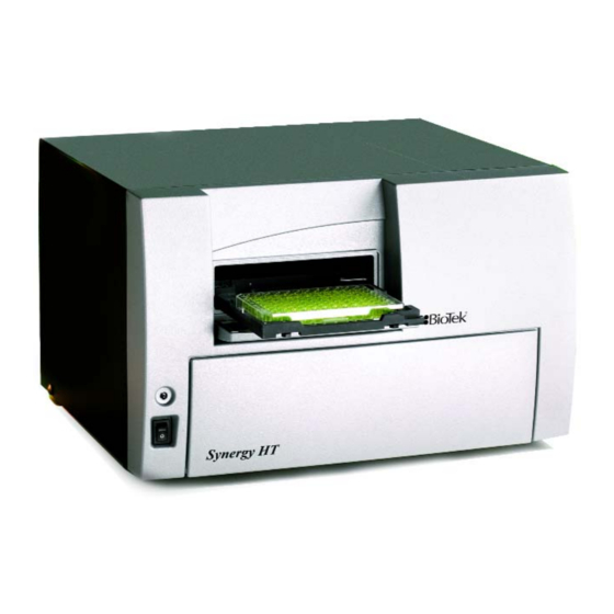
Page 24: Synergy™ Ht Multi-Mode Microplate Reader
Internal plate shaking is also supported. All Synergy HT models support the reading of 6-, 12-, 24-, 48-, 96-, and 384-well microplates with standard 128 x 86 mm geometry. Absorbance mode reads plates up to 0.8”…
-
Page 25: Features
Features | Features • Operated using BioTek’s Gen5™ or KC4™ Data Analysis Software • Dual-optics design, with separate fluorescence and absorbance channels • 3 mm top and 5 mm bottom fluorescence probes (standard configuration) • Optional 1.5 mm top/bottom, 3 mm bottom fluorescence probes (custom configurations) •…
-
Page 26: Package Contents
Chapter 1: Introduction Package Contents Part numbers are subject to change over time. Please contact BioTek Customer Care with any questions. • Microplate reader with Excitation and Emission filter wheels installed • Operator’s Manual (PN 7091000) • Documents, including (but not limited to): Warranty Statement, Certificate of Compliance and Calibration, Unpacking/Packing Instructions •…
-
Page 27: Optional Accessories
Additional Fluorescence Filters (contact BioTek for part numbers and availability) • Absorbance Liquid Test Solutions: BioTek Wetting Agent Solution (PN 7773002) BioTek QC Check Solution No. 1 (PN 7120779, 25 ml; or PN 7120782, 125 ml) • BioTek Sodium Fluorescein Powder (PN 98155) •…
-
Page 28: Product Support & Service
If your instrument(s) or software fails to function properly, if you have questions about how to use or maintain our products, or if you need to send an instrument to BioTek for service or repair, please contact our Technical Assistance Center. BioTek’s “TAC” is open from 8:30 AM to 5:30 PM (EST), Monday through Friday, excluding standard U.S.
-
Page 29: Chapter 2: Installation
Chapter 2 Installation This chapter includes instructions for unpacking and setting up the Synergy™ HT and, if applicable, the external dispense module. Instructions are also included for repackaging the reader and dispense module for shipment. Product Registration …………… 8 1: Unpack and Inspect the Reader ……….. 9 2: Remove the Shipping Panel ……….
-
Page 30: Product Registration
Chapter 2: Installation Product Registration If you have not already done so, please register your product(s) with BioTek to ensure that you receive important information and updates about the product(s) you have purchased. Register online through BioTek’s Customer Resource Center www.biotek.com…
-
Page 31: 1: Unpack And Inspect The Reader
1: Unpack and Inspect the Reader Important! Save all packaging materials. If you need to ship the reader to BioTek for repair or replacement, you must use the original materials. Using other forms of commercially available packaging, or failing to follow the…
-
Page 32: 2: Remove The Shipping Panel
See Package Contents in Chapter 1 for assistance with identifying the contents of the accessories box. Accessories box Vertical supports Shipping panel Inner shipping box Figure 1-B: Unpacking the reader’s inner shipping box BioTek Instruments, Inc.
-
Page 33: 2: Remove The Shipping Panel
Do not block any air vents. See Figure 3 on the next page. Place the panel back into the inner shipping box for storage. Important: Reattach the shipping panel before repackaging the Synergy™ HT for shipment. Synergy HT Operator’s Manual…
-
Page 34
Chapter 2: Installation Figure 2: Removing the shipping panel Figure 3: Storage pocket on the rear of the instrument (wrench, carrier shipping screw, and warning tag shown) BioTek Instruments, Inc. -
Page 35: 3: Remove The Microplate Carrier Shipping Screw
Figure 4: Removing the microplate carrier shipping screw Important: Replace the microplate carrier shipping screw before repackaging the Synergy HT for shipment. Please contact BioTek if you have misplaced the screw (PN 7092071) and/or its o-ring (PN 49259). Synergy HT Operator’s Manual…
-
Page 36: 4: Install The Fluorescence Lamp Assembly
Plug the lamp cables into the power source located to the right of the lamp. Either cable can be plugged into either socket. Close the hinged door. Figure 5: Installing the fluorescence lamp assembly (replacement lamp PN 7080500) BioTek Instruments, Inc.
-
Page 37: 5: Select An Appropriate Location
A clean work area is necessary to ensure accurate readings. Note: If you will be installing BioTek’s BioStack™ Microplate Stacker for operation with the Synergy HT, you may wish to seat the BioStack and the reader in their aligning plates at this time. Refer to the Installation chapter in the BioStack Operator’s Manual for more…
-
Page 38: 6: Connect The Power Supply
Plug the power cord into an appropriate power receptacle. Power inlet for injector models (as shown): 24 VDC 130 W Power inlet for non- injector models: 24 VDC center positive Figure 6: Power inlet on the rear of the instrument BioTek Instruments, Inc.
-
Page 39: 7: Unpack And Inspect The Dispense Module
This section applies to Synergy™ HT models with injectors only. Important! Save all packaging materials. If you need to ship the dispense module to BioTek for repair or replacement, you must use the original materials. Using other forms of commercially available packaging, or failing to follow the…
-
Page 40
2 reagent bottles 1 injector tip priming trough (small, plastic cup) 1 plastic tool storage bag with Velcro strips 2 metal thumbscrews 1 stylus (wire) packaged in a small plastic cylinder 1 dispense module cover 1 dispense module cable BioTek Instruments, Inc. -
Page 41
7: Unpack and Inspect the Dispense Module | Dispense module Top foam cable end cap Dispense module cover Inlet tubes (2) Syringes (2) Outlet tubes (4) Bottom foam end cap (with cutouts) Accessories Figure 9: Unpacking the dispense module’s accessories Synergy HT Operator’s Manual… -
Page 42: 8: Install The Dispense Module
See the photos on the next page. On the rear panel of the Synergy HT, identify the SYRINGE 1 SYRINGE 2 tubing ports. Remove the nylon screws from both ports. Open two of the plastic bags containing the…
-
Page 43
8: Install the Dispense Module | Figures 10 and 11: Possible locations for the dispense module, to the left or on top of the instrument. Outlet Inlet tubes tubes Syringe valves Figure 12: Initial setup of the dispense module Synergy HT Operator’s Manual… -
Page 44
Hold the syringe from rotating while tightening the thumbscrew. Finger-tighten only. The installed syringes should resemble the following: Syringes Syringe brackets Thumbscrews Figure 13: The dispense module with the syringes installed Continued on the next page. BioTek Instruments, Inc. -
Page 45
Dispenser Port Figure 14: Dispense module connected to the reader (rear view) Locate the injector tip-cleaning stylus , packaged in a small plastic cylinder. Attach the cylinder to the back of the dispense module for storage. Synergy HT Operator’s Manual… -
Page 46: 9: Connect The Host Computer
Figure 15: RS-232 serial and USB ports on the rear panel (injector model shown) 10: Install the Software on the Host Computer The Synergy™ HT is controlled by BioTek’s Gen5™ or KC4™ software running on a host computer. There is a certain sequence of events that must be followed to ensure that the software is properly installed and configured.
-
Page 47: 11: Turn On The Reader
Locate the power switch on the front panel and turn on the Synergy™ HT. The reader will automatically initiate a System Test and eject the microplate carrier. Figure 16: Carrier eject button (top) and power ON/OFF switch Synergy HT Operator’s Manual…
-
Page 48: 12: Establish Communication
If using the USB cable, did you install the driver software? (See 9: Connect the Host Computer If you remain unable to get Gen5 and the reader to communicate with each other, contact BioTek’s Technical Assistance Center. See page 6. BioTek Instruments, Inc.
-
Page 49: Using Kc4
If using the USB cable, did you install the driver software? (See 9: Connect the Host Computer If you remain unable to get KC4 and the reader to communicate with each other, contact BioTek’s Technical Assistance Center. See page 6. Synergy HT Operator’s Manual…
-
Page 50: 13: Run A System Test
If the problem is something you can fix, do so now and run another System Test. If the problem is something you cannot fix, or if the test continues to fail, contact BioTek’s Technical Assistance Center. See page 6 for contact information.
-
Page 51: 14: Test The Injector System
Insert the inlet tubes into the bottles. The dispense module’s setup should resemble the photo in Figure 18. Make any final adjustments, if necessary. Synergy HT Operator’s Manual…
-
Page 52: Register With Biotek
The fluid should pump through the tubing and dispense into the priming plate. Examine the fittings; no leaks should be detected. If leaks are detected, tighten all fittings and repeat the prime. If leaks are still detected, contact BioTek’s Technical Assistance Center. When the prime finishes, set Volume 2000 µl…
-
Page 53: Operational/Performance Qualification
Operational/Performance Qualification | Operational/Performance Qualification Your Synergy™ HT Multi-Detection Microplate Reader was fully tested at BioTek prior to shipment and should operate properly following the successful completion of the installation and setup procedures described throughout this chapter. If you suspect that problems occurred during shipment, if you received the reader back…
-
Page 54: Repackaging And Shipping Instructions
Please contact BioTek if you have misplaced either of these items. If you need to ship the Synergy HT and/or the dispense module to BioTek for service or repair, be sure to use the original packaging materials.
-
Page 55
Place four foam corner blocks around the inner shipping box. Close and seal the outer box with tape. Write the RMA number in large clear numbers on the outside of the box. Ship the box to BioTek (see page 6 for the address). Synergy HT Operator’s Manual… -
Page 56
Insert the top foam end cap. Close and seal the outer box with tape. Write the RMA number in large clear numbers on the outside of the box. Ship the box to BioTek (see page 6 for the address). BioTek Instruments, Inc. -
Page 57: Chapter 3: Getting Started
Chapter 3 Getting Started This chapter describes some of the Synergy™ HT’s key components and provides an introduction to using Gen5™ or KC4™ to control the instrument. Key Components …………..36 Power Switch, Carrier Eject Button, Microplate Carrier… 36 Lamp Assembly and Filter Wheel Access……37 Excitation and Emission Filter Wheels ………
-
Page 58: Key Components
In Gen5, this option is found in a Read step within a Procedure. In KC4, it is in the Reading Parameters dialog. Refer to the software documentation for further instructions. BioTek Instruments, Inc.
-
Page 59: Lamp Assembly And Filter Wheel Access
If there is a problem with the lamp, however, the intensity may drop and the run-time self-check will detect a low signal level and generate an error message. If this happens, the instrument will require service. Contact BioTek for assistance (this lamp is not user-replaceable). Synergy HT Operator’s Manual…
-
Page 60: Excitation And Emission Filter Wheels
Filter wheel 485/20 Thumbscrew Direction of light EMISSION 528/20 Filter wheel Note the difference in filter orientation between the Excitation and Emission filter wheels Figure 21: Profiles of the Excitation and Emission filter wheels, showing proper filter orientation BioTek Instruments, Inc.
-
Page 61
Remove the thumbscrew and slide the filter wheel’s supporting metal bracket straight out of the compartment. Note: The Emission filter wheel will “spring” out when removed. (This is because a shutter behind the wheel closes quickly to protect the PMT.) Synergy HT Operator’s Manual… -
Page 62
Clean both sides of the filter with lens paper. To reinstall a filter wheel: Ensure that all filters and/or plugs are inserted properly (see above). Slide the filter wheel back into its chamber. Replace the thumbscrew. Close the front door. Turn on the instrument. BioTek Instruments, Inc. -
Page 63: Installing The Time-Resolved Fluorescence Cartridge
200 to 999 nm in 1-nm increments, with a fixed bandwidth of 10 nm. The Synergy HT automatically detects the presence of the TR cartridge. At the start of a time-resolved fluorescence assay, the operator will be prompted to install the TR cartridge if it is missing.
-
Page 64: Configuring The System For Luminescence Measurements
‘Hole’ indicates the empty location in selecting ‘Lum/E’ indicates the empty the Emission filter wheel. See page 47 location in the Emission filter wheel. for information on Read steps and See page 53 for information on procedures. protocols. BioTek Instruments, Inc.
-
Page 65: The External Dispense Module
Outlet tubes transport fluid from the syringes into the instrument, through the tubing ports on the Synergy HT’s rear panel. The outlet tubes are opaque PTFE tubes with threaded fittings on each end that are used to deliver fluid from the syringes to the instrument.
-
Page 66
Syringe 1 Syringe 2 Bottom probe Figure 24: Close-up view of the injectors inside the instrument Note: The tubing and injectors should be cleaned at least quarterly. See Chapter 5, Preventive Maintenance for more information. BioTek Instruments, Inc. -
Page 67
Tip Prime before dispensing. The trough holds up to 1.5 ml of liquid and must be periodically emptied and cleaned by the user. Priming plate Tip priming trough Figure 25: Priming plate and tip priming trough Synergy HT Operator’s Manual… -
Page 68: Gen5 Software
Viewing/Updating the Filter and Wavelengths Tables The Synergy HT ships with a set of Excitation and Emission filters installed, and the reader’s onboard software is pre-configured with the filter values and their locations.
-
Page 69: Creating Protocols And Experiments
You’ll run the experiment to read plates and analyze the data. Figure 26: Defining the Procedure within a Gen5 Protocol Figure 27: An Experiment (containing measurement data), based on a pre-defined protocol Synergy HT Operator’s Manual…
-
Page 70
Select File|New Protocol Open the Procedure dialog. If prompted to select a reader, select the Synergy HT and click OK. Steps to the procedure for shaking or heating the plate, dispensing fluid, reading the plate, and more. Click the Validate… -
Page 71
When the read is complete, measurement values will appear in Gen5. To view them, select the desired data set (e.g., “528/20,645/40”) from the Data drop-down list. Select File|Save As and give the file an identifying name. Synergy HT Operator’s Manual… -
Page 72: Controlling The Dispense Module
, in L/second. Click to start the process. Prime When the process is complete, carefully remove the priming plate from the carrier and empty its contents. If the priming plate is empty, the prime volume was too low. BioTek Instruments, Inc.
-
Page 73
See “Install Dispense Module Components” in Chapter 2, Installation for information on installing/removing the syringes. Do not change the syringe positions or Important! calibrate the dispensers unless instructed to do so as part of installation, upgrade, or maintenance. Synergy HT Operator’s Manual… -
Page 74: Kc4 Software
Viewing/Updating the Filter and Wavelengths Tables The Synergy HT ships with a set of Excitation and Emission filters installed, and the reader’s onboard software is pre-configured with the filter values and their locations.
-
Page 75: Creating Protocols
Note: KC4 software versions 3.4 and greater offer a Multi-Mode option within the Reading Parameters dialog. This option allows you to define more than one detection method in a single protocol. See KC4’s Help system or User’s Guide for more information. Synergy HT Operator’s Manual…
-
Page 76
Sensitivity. Select a Plate Type Enable Temperature Control and/or Shaking if necessary. Select any Pre-Reading parameters. Click to verify the parameters and return to the main screen. Select Protocol|Save As and give the protocol an identifying name. BioTek Instruments, Inc. -
Page 77: Reading Plates
Place the plate on the carrier and click to begin the read. START READING When the read is complete, the measurement values will appear in KC4. Select Data|Save As and give the file an identifying name. Synergy HT Operator’s Manual…
-
Page 78: Controlling The Dispense Module
, in L/second. Click Prime to start the process. When the process is complete, carefully remove the priming plate from the carrier and empty its contents. If the priming plate is empty, the prime volume was too low. BioTek Instruments, Inc.
-
Page 79
‘1500 L remaining’ meaning the trough is empty. Note: When running a Read & Dispense protocol, KC4 may prompt you to empty the tip prime trough. In this case, KC4 will automatically open the System|Reader Control, Dispenser dialog. Synergy HT Operator’s Manual… -
Page 80
Chapter 2, Installation for information on installing/removing the syringes. Click to close the dialog. Important! Do not change the syringe positions or calibrate the dispensers unless instructed to do so as part of installation, upgrade, or maintenance. BioTek Instruments, Inc. -
Page 81: Recommendations For Achieving Optimum Performance
This effect varies with the brand of microplate and the solution composition. As the center of the meniscus drops and shortens the light path, the density readings change. The meniscus shape will stabilize over time. Synergy HT Operator’s Manual…
-
Page 82
When dispensing volumes less than or equal to 20 L/well, we recommend specifying a tip prime volume that is equal to the dispense volume. For dispense volumes greater than 20 L/well, we recommend a tip prime volume of 20 L. BioTek Instruments, Inc. -
Page 83: Chapter 4: Instrument Qualification
Chapter 4 Instrument Qualification This chapter contains procedures for qualifying the initial and ongoing performance of the Synergy™ HT and the external dispense module (if used). Overview …………….62 IQ/OQ/PQ …………….62 Recommended Qualification Schedule ……..64 System Test ……………. 65 Absorbance Plate Test…………
-
Page 84: Overview
Chapter 4: Instrument Qualification Overview Every Synergy™ HT reader and external dispense module is fully tested at BioTek prior to shipment and they should operate properly upon initial setup. If you suspect that a problem occurred during shipment, if you have received the equipment after returning it to the factory for service, and/or if regulatory requirements dictate that you qualify the equipment on a routine basis, you should perform the procedures outlined in this chapter.
-
Page 85
This frequency may be adjusted depending on the trends observed over time. • The successful completion of the PQ procedure confirms that the equipment is performing consistently under normal operating conditions. Synergy HT Operator’s Manual… -
Page 86: Recommended Qualification Schedule
** Liquid Test 3 is optional; it is provided for sites requiring verification at wavelengths lower than those attainable with the Absorbance Test Plate. Important! The risk factors associated with your assays may require that the Operational and Performance Qualification procedures be performed more frequently than shown above. BioTek Instruments, Inc.
-
Page 87: System Test
If this “power-up” System Test fails, the instrument will “beep” repeatedly. If this happens, press the carrier eject button to stop the beeping and then initiate a System Test through Gen5 or KC4 to retrieve the error code. Synergy HT Operator’s Manual…
-
Page 88: Procedure
If the test continues to fail, or if the cause is not something you can fix, contact BioTek’s Technical Assistance Center (see page 6 for contact information.)
-
Page 89
Lambda: 999 Gain: 4.49 Resets: 1 Channel: Air: 13084 39360 Dark: 9865 9911 Delta: 3219 29449 Figure 30-1: Sample output for the System Test (Sheet 1 of 3). The format varies depending on the software used. Synergy HT Operator’s Manual… -
Page 90
Middle Sensor: y= 11976 Tested: 11972 Delta: Back Sensor: x= 11588 y= 7964 Tested: 11580 7976 Delta: Figure 30-2: Sample output for the System Test (Sheet 2 of 3). The format varies depending on the software used. BioTek Instruments, Inc. -
Page 91
All Others: Tel: 802 655 4040 Fax: 802 655 3399 email: TAC@biotek.com Product support center: www.biotek.com/service Figure 30-3: Sample output for the System Test (Sheet 3 of 3). The format varies depending on the software used. Synergy HT Operator’s Manual… -
Page 92: Absorbance Plate Test
• Wavelength Accuracy: BioTek’s Absorbance Test Plate with the part number 7260522 contains a glass filter in position C6. This filter is used to check the wavelength accuracy of the reader. The filter is scanned across a specified wavelength range in 1-nm increments.
-
Page 93: Test Plate Certificates
Absorbance Plate Test | 71 Test Plate Certificates To run this test on the Synergy™ HT, you’ll need BioTek’s 7-Filter Absorbance Test Plate (PN 7260522) , with its accompanying certificates. • The Standards Certificate contains standard OD values for the filters at several different wavelengths (see the sample below).
-
Page 94: Setup: Gen5
Review all of the values you entered, and then click to save the data. The information you just entered will be available in Gen5 each time the Absorbance Plate Test is performed. The information must be updated whenever the Test Plate is recalibrated. BioTek Instruments, Inc.
-
Page 95: Procedure: Gen5
A sample test report is shown on pages 76 and 77. • Gen5 stores the results in a database; they can be retrieved and printed at any time. We recommend you print and save the report to document that the test was performed. Synergy HT Operator’s Manual…
-
Page 96: Setup: Kc4
• Note: If the Test Plate’s Peak Wavelength Certificate specifies multiple peak wavelength values, do not check ‘Peak Absorbance Search’. Run an independent test using spectral scan reads instead; see the special instructions on the next page. BioTek Instruments, Inc.
-
Page 97
Absorbance Test Plate using this protocol. Locate the peak wavelength on the graph (the wavelength value with the highest OD). Verify that it is within the allowed tolerance; see “Results & Troubleshooting Tips” on page 78. Synergy HT Operator’s Manual… -
Page 98
1.037 1.557 1.866 2.385 Result PASS PASS PASS PASS PASS PASS Figure 32-1: Sample output for the Absorbance Plate Test (page 1 of 2). Note: The format varies depending on the software used to run the test. BioTek Instruments, Inc. -
Page 99
Fax: 802 655 3399 email: TAC@biotek.com Product support center: www.biotek.com/service Figure 32-2: Sample output for the Absorbance Plate Test (page 2 of 2). Note: The format varies depending on the software used to run the test. Synergy HT Operator’s Manual… -
Page 100: Results & Troubleshooting Tips
Make sure the Test Plate is within its calibration certification period. The calibration sticker is affixed directly to the plate. If it is out of date, contact BioTek to schedule a recertification. Check the microplate carrier to ensure it is clear of debris.
-
Page 101
Test Plate’s Standards Certificate. Verify that the Test Plate is within its calibration certification period. The calibration sticker is affixed directly to the plate. If it is out of date, contact BioTek to schedule a recertification. • Repeatability: Repeatability is a measure of the instrument’s ability to read… -
Page 102: Absorbance Liquid Tests
Table 1: Typical Enzyme-Substrate Combinations and Stopping Solutions Enzyme Substrate Stopping Solution Alkaline o-nitrophenyl phosphate 3N sodium hydroxide Phosphate beta- o-nitrophenyl -beta-D 1M sodium carbonate Galactosidase galactopyranoside 2,2′-Azino di-ethylbenzothiazoline- Peroxidase citrate-phosphate buffer, pH 2.8 sulfonic acid (ABTS) Peroxidase o-phenylenediamine 0.03N sulfuric acid BioTek Instruments, Inc.
-
Page 103: Stock Solution Formulation
Make up to 1 liter with DI water; cap and shake well. Solution B Required Materials: • BioTek QC Check Solution No. 1 (PN 7120779, 25 mL; or PN 7120782, 125 mL) • Deionized water • 5-mL Class A volumetric pipette •…
-
Page 104: Liquid Test 1
± 1.0% ± 0.010 OD, then the expected range for the mean of the same well in its Turnaround (H12) position is 1.873 to 1.931 OD. 1.902 x 0.010 + 0.010 = 0.029; 1.902 — 0.029 = 1.873; 1.902 + 0.029 = 1.931 BioTek Instruments, Inc.
-
Page 105: Liquid Test 2
Note: The choice of dilutions and the absorbance of the original solution can be varied. Use Table 2 as a model for calculating the expected absorbances of a series of dilutions, given a different absorbance of the original solution. Synergy HT Operator’s Manual…
-
Page 106
Analysis ToolPak in Excel. Consult Excel’s help system for assistance. Since it is somewhat difficult to achieve high pipetting accuracy when conducting linear dilutions, an R Square value of at least 0.99 is considered adequate. BioTek Instruments, Inc. -
Page 107
H12 position is 1.873 to 1.931 OD. (1.902 x 1.0% = 0.019 + 0.010 = 0.029, which is added and subtracted from 1.902 for the range.) If the four corner wells are within the accuracy range, the reader is in alignment. Synergy HT Operator’s Manual… -
Page 108: Liquid Test 3
β-NADH Powder (β-Nicotinamide Adenine Dinucleotide, Reduced Form) Sigma bulk catalog number N 8129, or preweighed 10-mg vials, Sigma ® number N6785-10VL (or BioTek PN 98233). Note: Manufacturer part numbers are subject to change over time. Store the β-NADH Powder according to the guidelines on its packaging.
-
Page 109
A1. Since the standard deviation for well A1 is less than 0.013, the well meets the test criteria. • Repeatability Specification: ± 1.0% ± 0.005 OD from 0.000 to 2.000 OD ± 3.0% ± 0.005 OD from 2.000 OD to 3.000 OD Synergy HT Operator’s Manual… -
Page 110
Analysis ToolPak in Excel. Consult Excel’s help system for assistance. Since it is somewhat difficult to achieve high pipetting accuracy when conducting linear dilutions, an R Square value of at least 0.99 is considered adequate. BioTek Instruments, Inc. -
Page 111: Fluorescence Tests
2. Rerun the tests using your particular solutions, filters, microplates, etc. If results are comparable, then the results from these tests will be your baseline for future tests. 3. Be sure to document your new test procedure(s), and save all test results. Synergy HT Operator’s Manual…
-
Page 112: Required Materials
Mfr. ® #P4417, or equivalent) and pH meter or pH indicator strips with pH range 4 to 10 • Sodium Fluorescein Powder (1 mg vial, BioTek PN 98155) • Bottom optics: A clean Hellma Quartz 96-well titration plate (Mfr. ®…
-
Page 113: Test Solutions
Do not allow dust to settle on the surface of the solution; use plate covers or seals when not reading the plate. If using BioTek’s sodium fluorescein powder (PN 98155), be sure to hold the vial upright and open it carefully; the material may be concentrated at the top.
-
Page 114: Procedure
Pipette the solutions for the Corners, Sensitivity, and Linearity Tests into a clean 96-well quartz or glass-bottom microplate (see the map on page 94). • Read the plate using the ‘Synergy HT FI_B.prt’ protocol. 4. Perform the tests using the optics: •…
-
Page 115: Troubleshooting
Troubleshooting If any tests fail, please try the suggestions below. If the test(s) continue to fail, print the results and contact BioTek’s Technical Assistance Center. • Are the solutions fresh? The open buffer and stock solutions should be discarded after seven days.
-
Page 116: Pipette Map
Aspirate 150 µL from wells C5-F5 and discard. CBUF CBUF CBUF CBUF CBUF CBUF CBUF CBUF CBUF CBUF 0.25 0.125 0.062 0.25 0.125 0.062 0.25 0.125 0.062 0.25 0.125 0.062 CBUF CBUF CBUF CBUF CBUF CBUF CBUF CBUF CBUF CBUF BioTek Instruments, Inc.
-
Page 117: Gen5 Protocol Reading Parameters
Plate Type or Sensitivity (see “Troubleshooting” on page 93). The Plate Type setting should match the plate you are actually using. Protocol Name: ‘Synergy HT FI_B.prt’ Parameter Setting Plate Type: “Greiner SensoPlate”…
-
Page 118: Kc4 Protocol Reading Parameters
Plate Type or Sensitivity (see “Troubleshooting” on page 93). The Plate Type setting should match the plate you are actually using. Protocol Name: ‘Synergy HT FI_B.prt’ Parameter Setting Reading Type:…
-
Page 119
To create a plate format in KC4™ for the Greiner SensoPlate, select System > Plate Formats , click , and add the information shown below: Once the plate format is created, you can reference it in a protocol’s Reading Parameters dialog. Synergy HT Operator’s Manual… -
Page 120: Fluorescence Tests Using Methylumbelliferone
Excitation filter 360/40 nm, Emission filter 460/40 nm • Deionized or distilled water • Carbonate-Bicarbonate buffer (“CBB”) capsules (BioTek PN 98158) • 10 mg vial of Methylumbelliferone (MUB) (BioTek PN 98156) • 100% methanol (BioTek PN 98161) • Aluminum foil •…
-
Page 121
Top 3 mm 0.16 ng/mL Top 1.5 mm 0.31 ng/mL Linearity Test 1. Calculate the Mean of the four wells for each concentration in columns 1-5. 2. Perform linear regression using these values as inputs: Synergy HT Operator’s Manual… -
Page 122
Mix the wells using the pipette. Do not discard the tips. • Aspirate 150 µL from wells C4-F4 and dispense it into wells C5-F5. Mix the wells using the pipette. • Aspirate 150 µL from wells C5-F5 and discard. 12.5 6.25 12.5 6.25 12.5 6.25 12.5 6.25 BioTek Instruments, Inc. -
Page 123
Your tests may require modifications to some of the parameters below, such as Plate Type or Sensitivity (see “Troubleshooting” on page 93). The Plate Type setting should match the plate you are actually using. The following tables contains the recommended settings for the ‘Synergy HT FI_MUB.prt’ protocol. GEN5 USERS Protocol Name: ‘Synergy HT FI_MUB.prt’… -
Page 124: Dispense Module Tests
Dispense Module Tests This section applies to Synergy™ HT models with injectors only. BioTek Instruments, Inc. has developed a set of tests that you can perform to ensure that the dispense module performs to specification initially and over time. We recommend that you perform these tests before first use (e.g., during the Initial OQ), and then every three…
-
Page 125: Required Materials
± 1.0% ± 0.010 OD or better and a repeatability specification of ± 1.0% ± 0.005 OD or better. Note: The Synergy HT reader may be used if it has passed the Absorbance Plate Test and the Absorbance Liquid Tests described earlier in this chapter.
-
Page 126: Test Solution Recipes
1.300 and 1.700 OD at 405/750 nm. It is assumed that the solutions used are at room temperature. If you do not have BioTek’s Green Test Dye Solution (PN 7773003), prepare a green test dye solution using one of the following methods: Using BioTek’s Blue and Yellow Concentrate Dye Solutions:…
-
Page 127: Test Setup: Gen5
BioTek absorbance reader, create two additional Read protocols. See page 115 for instructions. • If you are not using a BioTek absorbance reader, prepare your reader to perform two reads with the following characteristics: 80 μl Read 20 & 5 μl Read Primary Wavelength…
-
Page 128: Test Procedure: Gen5
Test Procedure: Gen5™ Prime both dispensers with deionized or distilled water. • Ensure that the tip priming trough (BioTek PN 7082118) is installed in the microplate carrier. • Place a clean priming plate (BioTek PN 7132158 or 7092135) on the carrier.
-
Page 129
Repeat steps 4–9 using the Synergy HT Dispenser 2.prt protocol. See page 109 for instructions for analyzing the results. When all tests are complete, prime both dispensers with at least 5000 µL of deionized or distilled water, to flush out the green dye solution. -
Page 130: Test Procedure: Kc4
Chapter 4: Instrument Qualification Test Procedure: KC4™ Note: If you are using one of BioTek’s keypad-based readers, such as the ELx800™ or ELx808™, make sure the reader is not running in Rapid mode. To check the setting, select UTIL READ and cycle through the options until READ IN RAPID MODE? appears.
-
Page 131: Results Analysis
If any tests fail, prime the fluid lines and rerun the test(s). If the test(s) fail again, the injector heads may require cleaning (see Chapter 5, Preventive Maintenance If tests continue to fail, contact BioTek’s Technical Assistance Center. Synergy HT Operator’s Manual…
-
Page 132: Creating Test Protocols Using Gen5
Creating the Test Protocols Using Gen5™ This section contains instructions for creating two Gen5 protocols specifically for performing the Synergy HT Dispense Precision and Accuracy test. Refer to the Gen5 Help system to learn more about using Gen5, and for complete instructions for creating protocols.
-
Page 133
When the Plate Out/In step is executed, Gen5 displays its comment in a message box, as demonstrated below: Figure 34: Sample comment associated with a Plate Out/In step, presented to the operator at the start of the experiment. Synergy HT Operator’s Manual… -
Page 134
Read Speed: Normal Two Wavelengths: 405 and 750 nm Read Step label: “20 and 5 ul Read_Disp 1” (or _Disp 2) Wells: A5..H12 Detection Method: Absorbance Read Type: Endpoint Read Speed: Normal Two Wavelengths: 630 and 750 nm BioTek Instruments, Inc. -
Page 135
‘Delta OD 80 ul_Disp 1’ (see sample screen on the next page). Clear Use single formula for all wells. In the Current Formula field, type DS1-DS2 and then highlight wells to assign the formula. Synergy HT Operator’s Manual… -
Page 136
When you’re finished, the Data Reduction Steps list will show two Delta OD transformations: Click to close the Data Reduction dialog. Select File|Save As and give the protocol an identifying file name, such as “Synergy HT Dispenser 1.prt.” BioTek Instruments, Inc. -
Page 137: Creating Test Protocols Using Kc4
To perform the Dispense Accuracy and Precision tests, you’ll need to create a total of Dispense protocols in KC4 (three per dispenser). If you will be using one of BioTek’s absorbance readers (including the Synergy HT), you’ll need to create additional protocols for reading the plate after the dispenses.
-
Page 138
(as shown below) to open the Dispense dialog, and change the Dispenser Return to the main menu and select Protocol|Save As . Modify the file name so that it includes dispenser number (e.g., Dispenser 2_80 ul). BioTek Instruments, Inc. -
Page 139
. Assign wells to the plate as shown on page 119. Click to return to the main menu. Select Protocol|Save As and give the protocol an identifying name that includes the dispense volume, such as Delta 80 and Delta 20 and 5. Synergy HT Operator’s Manual… -
Page 140
Chapter 4: Instrument Qualification Sample KC4 Reading Parameters Dialog for the 80 µL Read Protocol, using the Synergy HTTR w/Injectors Sample KC4 Reading Parameters Dialog for the 20 & 5 µL Read Protocol, using the ELx808 BioTek Instruments, Inc. -
Page 141
Dispense Module Tests | 119 Sample KC4 Plate Layout for the 80 µL Read Protocol Sample KC4 Plate Layout for the 20 & 5 µL Read Protocol Synergy HT Operator’s Manual… -
Page 142
Chapter 4: Instrument Qualification BioTek Instruments, Inc. -
Page 144
Chapter 4: Instrument Qualification BioTek Instruments, Inc. -
Page 145: Chapter 5: Preventive Maintenance
Chapter 5 Preventive Maintenance This chapter provides step-by-step instructions for maintaining the Synergy™ HT and external dispense module (if used) in top condition, to ensure that they continue to perform to specification. Recommended Maintenance Schedule ……..124 Overview ……………124 Dispense Module………….124 Schedule ……………124 Warnings &…
-
Page 146: Recommended Maintenance Schedule
(review the reagent’s package insert for specific recommendations). A daily cleaning regimen is the best way to ensure accurate performance and a long- life for your instrument and dispense module. BioTek also recommends flushing the module with DI water before conducting the decontamination procedure described in…
-
Page 147
Recommended Maintenance Schedule | Frequency Tasks for Synergy HT Models without Injectors Quarterly As Needed Task Page Clean Exposed Surfaces Inspect/Clean Excitation and Emission Filters Decontamination (see Appendix A) Before shipment or storage Frequency Tasks for Synergy HT Models with Injectors… -
Page 148: Warnings & Precautions
“wet” cloth on it. Do not allow water or other cleaning solution to run into the interior of the instrument. If this happens, contact BioTek’s Technical Assistance Center. Important! Do not apply lubricants to the microplate carrier or carrier track.
-
Page 149: Cleaning Exposed Surfaces
“wet” cloth. Do not allow the cleaning solution to run into the interior of the instrument. If this happens, contact BioTek’s Service Department. Exposed surfaces may be cleaned (not decontaminated) with a cloth moistened (not soaked) with water or water and a mild detergent. You’ll need: •…
-
Page 150: Inspecting/Cleaning Excitation And Emission Filters
Clean the filters using lens-cleaning tissue moistened with a small amount of isopropyl, ethyl, or methyl alcohol. Ensure that the filters remain in their current locations. Replace the filter wheel brackets in their respective positions and replace the thumbscrews. Close the hinged door. BioTek Instruments, Inc.
-
Page 151: Flushing/Purging The Fluid Path
When the purge is complete, repeat the process for Dispenser 2 After purging the system, you may wish to run a quick Dispense protocol to visually verify the dispense accuracy. See the next page for instructions for creating the protocol. Synergy HT Operator’s Manual…
-
Page 152: Running A Dispense Protocol (Optional)
Read step to the list. Click to close the Procedure. Select File|Save As and give the protocol an identifying name, such as “Dispense Observation.” Select File|New Experiment to run the Dispense Observation protocol. Click the Read button and follow the prompts. BioTek Instruments, Inc.
-
Page 153
Run the two protocols on two different plates. When finished, visually assess the fluid level in the wells for accuracy. If the well volume appears to be unevenly distributed, clean the internal dispense tubes and injector heads as described in on page 133. Cleaning Internal Components Synergy HT Operator’s Manual… -
Page 154: Emptying/Cleaning The Tip Priming Trough
Clean the priming plate regularly to prevent bacteria growth and residue buildup. Wash the plate in hot soapy water, using a small brush to clean in the corners if necessary. Rinse thoroughly and allow it to dry completely. BioTek Instruments, Inc.
-
Page 155: Cleaning The Internal Components
Cleaning the Internal Components | Cleaning the Internal Components Applies only to Synergy™ HT models with injectors. The Synergy HT’s internal components that require routine cleaning include: • Optical probes • Surface beneath the microplate carrier • Internal dispense tubes and injector heads The internal components should be cleaned at least quarterly.
-
Page 156: Required Materials
Deionized or distilled water • Stylus (stored in a plastic cylinder affixed to the rear of the dispense module or reader) (PN 2872304) For cleaning the optical probes: • Clean cotton swabs • Isopropyl alcohol • Lens-cleaning tissue BioTek Instruments, Inc.
-
Page 157: Removing The Reader’s Shroud
PC, and the dispense module. Disconnect power and all cables. Set the external dispense module aside. Place the Synergy HT on a work surface that allows you to easily access all sides of the instrument. Remove four black Phillips-head screws: one at the bottom rear corner on each side, and two at the top center of the rear panel.
-
Page 158
Chapter 5: Preventive Maintenance Stand facing the front of the instrument. Grasp both sides of the shroud, slide it toward you, and pull it straight off the instrument. Set the shroud aside. BioTek Instruments, Inc. -
Page 159: Removing The Internal Tubes And Injector Heads
Important! When reinstalling the internal dispense tubes, be sure to align the tubing ports with the injector heads as shown in this diagram. Look for the SYRINGE 1 SYRINGE 2 labels on the instrument’s rear panel. Synergy HT Operator’s Manual…
-
Page 160
Locate the tubing ports on the reader’s rear wall. Turn each tube’s thumbscrew counterclockwise and gently pull the tube from the port. Cable clamp Locate the injector heads. Turn each tube’s thumbscrew counterclockwise to disconnect the tube from the injector head. BioTek Instruments, Inc. -
Page 161
Cleaning the Internal Components | Turn the injector heads counterclockwise and gently pull them out of their sockets. Note: Be sure to seat the injector tips securely when reinstalling. See the photo on page 150. Synergy HT Operator’s Manual… -
Page 162: Cleaning The Internal Tubes And Injector Heads
Stream water from a faucet through the pipe to be sure it is clean. If the water does not stream out, try soaking the heads in hot soapy water and then reinserting the stylus. O-ring; do not remove BioTek Instruments, Inc.
-
Page 163: Cleaning The Optical Probes
(cover). If you haven’t already done this, turn to page 135 now for instructions. Note: For models without injectors, the internal chamber and probes are not customer-accessible. Contact BioTek’s Technical Assistance Center with any questions about your particular model. •…
-
Page 164
Top optical probe Screw for lowering and raising the top optical probe Incubator Top probe hanger, with housing two shoulder screws Figure 38: Internal components to be removed/adjusted for cleaning the optic probes BioTek Instruments, Inc. -
Page 165
Disconnect the heater and thermistor wires. To do this, depress the small tab (pictured below) and separate the connectors. Depress tab to separate the connectors Remove the thumbscrew located in the left rear of the instrument and set it aside. This exposes the ground wire. Synergy HT Operator’s Manual… -
Page 166
Chapter 5: Preventive Maintenance Lift the ground wire and move it off to the side. Locate the two black thumbscrews that hold the incubator housing in place. Remove both of them and set them aside. BioTek Instruments, Inc. -
Page 167
Gently lift the left side of the incubator housing and carefully slide it out. Note: When replacing the incubator housing, the two “forks” on its right side should wrap around the holding screws. The forks should not slide under the fixed foam housing. Synergy HT Operator’s Manual… -
Page 168
Gently pull the optical probe up and out of its socket to expose it for cleaning. Soak the probe in alcohol for one minute maximum . Wipe with lens-cleaning tissue and set aside. Clean with alcohol and lens tissue BioTek Instruments, Inc. -
Page 169
(see instructions on the next page). Do not touch the lens with your fingers! Inspect the block for spills or other contamination. Carefully clean with mild detergent if necessary. Absorbance Lens Probe hanger (bottom view) Synergy HT Operator’s Manual… -
Page 170
Important! When cleaning the absorbance lens with the swab, apply very little pressure to the lens! Applying too much pressure can push the lens out of its holder; reinstallation must be performed by BioTek service personnel. If the lens does fall out, contact BioTek TAC. -
Page 171: Cleaning The Reader’s Internal Surface
Microplate carrier, fully extended Moisten ( do not soak ) a clean cotton cloth with alcohol, water, or with water and mild detergent. Wipe all sides of the plate carrier. Wipe the instrument’s horizontal surface. Synergy HT Operator’s Manual…
-
Page 172: Reassembling The Components
The knurled plastic should sit flush against the hanger surface, as shown below. Attach the two internal dispense tubes to the injector heads, as shown below. Do not overtighten the thumbscrews! Continued on the next page. BioTek Instruments, Inc.
-
Page 173: Performance Check
After reassembling the instrument, perform the following to verify that the instrument is functioning properly: • Plug the instrument in and turn it on; allow its run-time system test to complete. Run a System Test through Gen5™ or KC4™. • Run any required OQ/PQ tests. Synergy HT Operator’s Manual…
-
Page 174
Chapter 5: Preventive Maintenance BioTek Instruments, Inc. -
Page 175: Appendix A: Decontamination
Appendix A Decontamination This appendix contains procedures for decontaminating all models of the Synergy™ HT. Purpose …………….154 Required Materials……………155 Procedure for Models without Injectors ……..156 Routine Procedure for Models With Injectors ……157 Clean Exposed Surfaces………..157 Decontaminate the Fluid Lines ……….158 Rinse the Fluid Lines …………159 Clean the Internal Tubing and Injector Heads …..159 Clean the Tip Priming Trough and Priming Plate ….160…
-
Page 176: Purpose
Centers for Disease Control and Prevention (CDC). Neither BioTek nor the CDC assumes any liability for the adequacy of these solutions and methods. Each laboratory must ensure that decontamination procedures are adequate for the Biohazard(s) they handle.
-
Page 177: Required Materials
Biohazard trash bags • 125 ml beakers • Clean, lint-free cotton cloths Additional materials for models with injectors: • Phillips-head screwdriver • Small brush for cleaning the tip priming trough and priming plate • (Optional) Mild detergent Synergy HT Operator’s Manual…
-
Page 178: Procedure For Models Without Injectors
Do not immerse the instrument, spray it with liquid, or use a “wet” cloth. Do not allow the cleaning solution to run into the interior of the instrument. If this happens, contact the BioTek Service Department. Important! Turn off and unplug the instrument for all decontamination and cleaning operations.
-
Page 179: Routine Procedure For Models With Injectors
Note: Perform this Routine Procedure when all systems are functioning normally on the Synergy™ HT with Injectors. If you are unable to prime the Synergy HT due to a system failure, perform the Alternate Procedure described on page 161. If disinfecting with sodium hypochlorite (bleach), be sure to flush repeatedly with deionized water to ensure that no bleach is carried over.
-
Page 180: Decontaminate The Fluid Lines
Put the tubes back in. Important! If sodium hypochlorite (bleach) was used, perform Rinse the Fluid Lines on the next page. Otherwise, (or after performing the Rinse procedure), repeat steps 1-13 for SYRINGE 2 Dispenser 2 BioTek Instruments, Inc.
-
Page 181: Rinse The Fluid Lines
• Required Materials • Removing the Reader’s Shroud • Removing the Internal Tubes and Injector Heads • Cleaning the Internal Tubes and Injector Heads When finished, replace the internal components and the reader’s shroud. Synergy HT Operator’s Manual…
-
Page 182: Clean The Tip Prime Trough And Priming Plate
If decontaminating with alcohol , remove the trough and plate and let them air dry. Discard the used gloves and cloths using a Biohazard trash bag and an approved Biohazard container. Figure 39: Tip priming trough and priming plate BioTek Instruments, Inc.
-
Page 183: Alternate Procedure For Models With Injectors
Use the cloth to wipe: • All surfaces of the shroud • All surfaces of the plate carrier • The instrument’s rear panel • The exposed surfaces of the dispense module, including the syringe valves Continued on the next page. Synergy HT Operator’s Manual…
-
Page 184
Use a clean, dry cloth to dry all wet surfaces on the instrument and the Dispense module. Reassemble the instrument and dispense module as necessary. Discard the used gloves and cloths using a Biohazard trash bag and an approved Biohazard container. BioTek Instruments, Inc. -
Page 185: Appendix B: Computer Control
Computer Control The Synergy™ HT is completely computer-controlled; it is not equipped with a keypad or its own user interface. BioTek’s Gen5™ and KC4™ software packages support all Synergy HT models and are used for both instrument control and data reduction.
-
Page 186
Appendix B: Computer Control BioTek Instruments, Inc. -
Page 187: Appendix C: Error Codes
Appendix C Error Codes This section lists and describes the possible error codes that may appear on the controlling PC. Error Codes …………….166 Fatal Errors…………..167 Non-Fatal Errors ………….168 Home Sensor Initial Find Errors (0100-0307) ….168 Home Sensor Verification Errors (0400-0409) ….172 Saturation Errors (0500-0616) ……..174 Absorbance Reader Noise Errors (0700-0A16) ….180 Internal Self-Test Errors (0D00-2918) ……184…
-
Page 188: Error Codes
If you need help or more information, contact BioTek’s Technical Assistance Center. See page 6 for contact information. For errors that are displayed during operation of the Synergy HT with the BioStack™ Microplate Stacker, refer to the BioStack Operator’s Manual.
-
Page 189: Fatal Errors
Error Codes | Fatal Errors Fatal errors indicate conditions that require immediate attention. If a fatal error is displayed, contact BioTek’s Technical Assistance Center for further instructions. Code Description Task block not available A100 control A200 Read already in progress…
-
Page 190: Non-Fatal Errors
Loosen the two screws and slide the PCB to the right and retighten. Run the carrier autocal for both absorbance and fluorescence. • Carrier is not able to move into read chamber. An object may be obstructing the carrier’s path. • See Field Change Notice L0030. BioTek Instruments, Inc.
-
Page 191
• Filter wheel is not moving because it is too close to the motor gear and is binding. • Defective or broken optical sensor. • Defective motor, Motor Controller PCB, or cable. • Motors failed due to the bearings. Synergy HT Operator’s Manual… -
Page 192
• Defective motor, Motor Controller PCB, or cable. • Cable between the dispenser and the Synergy is defective, too long, or there is a lost connection. • For certain older dispensers, opto cable 7330506 may need to be replaced with 7120734. BioTek Instruments, Inc. -
Page 193
This error is caused when the Order-sorting Filter Wheel cannot rotate to the home sensor position. Probable Causes: • The motor or motor driver circuit is defective. • The home sensor or sensor circuit is defective. Synergy HT Operator’s Manual… -
Page 194: Home Sensor Verification Errors (0400-0409)
Probable Causes: • The optical trigger flag has moved or is loose. • Dirty rail, nylon bushings, or bearings. • Carrier support pin is out of adjustment. • Reference Field Change Notice L0030. BioTek Instruments, Inc.
-
Page 195
Reference Field Change Notice L0031. • Fiber-optic cable is not tied to the upper probe assembly, and has moved into the top probe’s path, not allowing the top probe to reach the optical sensor. Synergy HT Operator’s Manual… -
Page 196: Saturation Errors (0500-0616)
(filter wheels homing), a 0500 error could indicate a missing filter. In this case, a 0501 would indicate a missing filter in position 1 of the wheel, which was last homing prior to the error condition being detected. BioTek Instruments, Inc.
-
Page 197
PCB sent the wrong voltage request to the lamp power supply. Scenario 4 (fluorescence autocalibration): • The surface of the autocalibration jig is too reflective. Return the jig to BioTek for a replacement jig. • The carrier did not move far enough to block the light beam. Troubleshoot the carrier movement. -
Page 198
• Voltage to the lamp has increased due to failure of the lamp power supply, or the motor power supply PCB sent the wrong voltage request to the lamp power supply. BioTek Instruments, Inc. -
Page 199
• Voltage to the lamp has increased due to failure of the lamp power supply, or the motor power supply PCB sent the wrong voltage request to the lamp power supply. Synergy HT Operator’s Manual… -
Page 200
• Voltage to the lamp has increased due to failure of the lamp power supply, or the motor power supply PCB sent the wrong voltage request to the lamp power supply. BioTek Instruments, Inc. -
Page 201
• Missed flashes or an erratic flash lamp. • Voltage to the lamp has decreased due to failure of the lamp power supply, or the motor power supply PCB sent the wrong voltage request to the lamp power supply. Synergy HT Operator’s Manual… -
Page 202: Absorbance Reader Noise Errors (0700-0A16)
• There may be an ambient light leak. Ensure the plate carrier door and the front hinged door are properly closed. • Analog PCB failure; the photodetector is noisy. • Faulty analog PCB or faulty internal grounding may cause internal electronic noise. BioTek Instruments, Inc.
-
Page 203
• A faulty analog PCB or faulty internal grounding may cause internal electronic noise. • There may be an ambient light leak. Make sure the plate carrier door and the front hinged door are properly closed. • Electrical noise may be penetrating the measurement chamber. The bottom and top Synergy HT Operator’s Manual… -
Page 204
• Reference channel photodetector is defective or the optic spray is damaged. • A faulty analog PCB or faulty internal grounding may cause internal electronic noise. • There may be an ambient light leak. Make sure the plate carrier door and the front hinged BioTek Instruments, Inc. -
Page 205
• Absorbance analog PCB or measurement channel analog PCB is defective. • Shielding of the cable between measurement channel and analog PCB is defective or disconnected. • Measurement channel photodetector is defective or the optic spray is damaged. Synergy HT Operator’s Manual… -
Page 206: Internal Self-Test Errors (0D00-2918)
< 1 or > 8 to fail.) The last number is the lambda table position number. Probable Causes: • The wavelength was not calibrated prior to the read. • The gain test skipped or failed for this wavelength. BioTek Instruments, Inc.
-
Page 207
• Order-sorting filter wheel is jammed, not aligning the correct bandpass filter with the light path and white light is passing through, or the filter is degraded and is not passing enough light energy or is blocking the light. • Damaged optic spray. Synergy HT Operator’s Manual… -
Page 208
This error indicates that during self-test or at the end of a plate read, the checksums calculated for configuration flash memory page 0 do not match the saved checksums. Probable Causes: • The flash memory on the 7080400 PCB is defective or corrupt. The basecode software may need to be re-downloaded. BioTek Instruments, Inc. -
Page 209
0200 1301 Y-axis 0201 1302 EX motor 0202 1303 EM motor 0203 1304 Order-sorting filter wheel 0204 1305 Monochromator 0405 1306 Probe Height 0206 1307 Probe changer 0207 1308 Syringe 1 0208 1309 Syringe 2 0209 Synergy HT Operator’s Manual… -
Page 210
Zone 2, 3, and 4 150F Zone 1, 2, 3, and 4 Probable Causes: • Thermistor is defective for that zone. • Heating pad is defective. • Motor power supply PCB is defective. • Incubation chamber is less than 12ºC. BioTek Instruments, Inc. -
Page 211
Zone 3 and 4 151D Zone 1, 3, and 4 151E Zone 2, 3, and 4 151F Zone 1, 2, 3, and 4 Probable Causes: • Thermistor is defective for that zone. • Motor power supply PCB is defective. Synergy HT Operator’s Manual… -
Page 212
This error indicates that the combination of assay parameters results in more kinetic reads than supported by the software. • Change the assay parameters to reduce the number of total kinetic reads. Note: The Synergy HT supports kinetics through computer control only. BioTek Instruments, Inc. -
Page 213
30 seconds, and then turning the instrument back on. Probable Causes: • The memory is corrupt. Replace the processor PCB. • If the error persists, contact BioTek TAC. 1C00 A/D calibration STBY line never went low… -
Page 214
• Defective Motor Controller PCB. • Shipping screw was not installed before moving the unit, and the XY sensor was damaged. • Something moved the carrier while it was extended. • Faulty motor gear attachment (set screw loose). BioTek Instruments, Inc. -
Page 215
This error indicates that during a self-test, the lamp did not indicate that it was off. Probable Causes: • The sense resistor is damaged on the 7090402 PCB. • Cable between the lamp PCB and motor power supply PCB is defective. • Motor power supply PCB is defective. Synergy HT Operator’s Manual… -
Page 216
This test is performed when the instrument is first turned on and then tested periodically during background functions. Probable Causes: • The lamp is weak or defective—change the lamp (BioTek PN 7080500). • The sense resistor is damaged on the 7090402 PCB. • The regulator mounted on the 7090402 PCB is defective. -
Page 217
2912 2902 2913 2903 2914 2904 2915 2905 2916 2906 2917 2907 2918 2908 Probable Causes: • The motor power supply PCB is defective. • The sense resistor is damaged on the motor power supply PCB. Synergy HT Operator’s Manual… -
Page 218: Other Errors (2A00-4000)
• Syringe was not installed correctly or was not cleaned, causing stress on syringe movement by not allowing the syringe to move to the home position. • The syringe valve did not open. • The glue between the lead screw and the motor has separated. BioTek Instruments, Inc.
-
Page 219
This error indicates that the calibration data has been entered but the checksum failed. This corresponds to the 6 calibration values. Note: This error can apply to either Syringe 1 or Syringe 2. Probable Causes: • Values entered are corrupted or incorrect. Synergy HT Operator’s Manual… -
Page 220
• The filters defined in the filter table do not match the filter wheels. • The user did not send the filter table information to the reader after making changes to the table in the controlling software. BioTek Instruments, Inc. -
Page 221
Z position. The distance between the top of the autocalibration jig and the homing opto sensor is <= 24 full steps. Probable Causes: • Linear way is dirty or needs lubrication. • Homing opto sensor is defective. Synergy HT Operator’s Manual… -
Page 222
Required carrier outside when locked in If the carrier is inside the read chamber and the probe needs to move down but the door is locked, the carrier cannot move out of the way of the top probe assembly. BioTek Instruments, Inc. -
Page 223
151 152 153 154 155 156 157 158 159 15A 15B 15C 15D 15E 15F 160 161 162 163 164 165 166 167 168 169 16A 16B 16C 16D 16E 16F 170 171 172 173 174 175 176 177 178 179 17A 17B 17C 17D 17E 17F 180 Synergy HT Operator’s Manual… -
Page 224: Status String Format
A/D calib STBY transition not detected OVERLAP ERR “1F00” bandpass overlap in filterset INVALID PARAM ERR “2100” invalid parameter value selected PMT ERR “2200” PMT test signal out of range <test type> SENSOR POS ERR “2400” <motor> failed verify at test sensor BioTek Instruments, Inc.
-
Page 225
Motor Codes <lowest digit in returned error code> Carrier X-Axis “0” Carrier Y-Axis “1” Excitation Filter Wheel “2” Emission Filter Wheel “3” Monochromator Filter Wheel “4” Monochromator “5” Probe Height Axis “6” Probe Changer “7” Dispenser Syringe 1 “8” Dispenser Syringe 2 “9” Synergy HT Operator’s Manual… -
Page 226
TWO BOTTOM INJECTORS “8” only one injector can be at bottom position BioTek Instruments, Inc. -
Page 227
SHAKE START TIME “31” shake start time out of range READ EVENT EXPECTED “32” read event must follow shake event with repeat SHAKE TIME “33” shake time out of range Synergy HT Operator’s Manual… -
Page 228
Column = (well code) — ((row-1) * (columns in plate)). Ex: 87 — ((8 — 1) * 12) = column 3. Note: If this code is returned in response to a Run Area Scan (‘c’) command, it indicates the scanned point (left-to-right) that caused the error. BioTek Instruments, Inc. -
Page 229: Appendix D: Specifications
Appendix D Specifications This appendix contains BioTek’s published specifications for the Synergy™ HT. Specifications …………..208 Microplates……………..208 Hardware and Environmental ……….208 Absorbance …………….209 Fluorescence …………..211 Incubation…………….213 Shake…………….213 Injector Model …………..213…
-
Page 230: Specifications
16” D x 15” W x 10” H (40.6 cm x 38 cm x 25.4 cm) Weight: 38 lb. (17 kg) Environment: Operational temperature 18º to 40°C Humidity: 10% to 85% relative humidity (non-condensing) 100 VA max, 130 VA max with injectors Power Consumption: BioTek Instruments, Inc.
-
Page 231: Absorbance
0.000 to 1.000 OD ± 2.0% ± 0.010 OD Sweep mode, 96- and 384-well plates For the above performance, the Gain on the Optics Test should be below 10.0. Optics range: 200 to 999 nm accuracy: ± 2 nm repeatability: ± 0.2 nm bandpass: 2.4 nm Detector: Photodiodes (2) Synergy HT Operator’s Manual…
-
Page 232
309 sec Rapid Read Mode 121 sec 232 sec Sweep Read Mode 38 sec 65 sec Single Kinetic, 96-well plate: 630 nm Normal Read Mode 49 sec Rapid Read Mode 39 sec Sweep Read Mode 14 sec BioTek Instruments, Inc. -
Page 233: Fluorescence
275 sec Optical Probes The Synergy HT is configured with a variety of probe sizes: 1.5 and 3 mm probes can be installed in either the top or bottom positions; the 5 mm probe can only be installed in the bottom position.
-
Page 234
300 µL per well signal-to-noise ratio greater than 2.0 Excitation 360/40, Emission 460/40 Corning Costar black strips ® Optional Time-Resolved Fluorescence • Delay 0 or 20 µs to 16000 µs • Integration interval 20 to 16000 µs • Times adjustable in 10 µs increments BioTek Instruments, Inc. -
Page 235: Incubation
0.1% Tween 20, and dye at room temperature: < 2.0% for volumes of 50-200 µL < 4.0% for volumes of 25-49 µL < 7.0% for volumes of 10-24 µL < 10.0% for volumes of 5-9 µL Synergy HT Operator’s Manual…
-
Page 236
Appendix D: Specifications BioTek Instruments, Inc. -
Page 237: Appendix E: Instrument Dimensions For Robotic Interface
Appendix E Instrument Dimensions for Robotic Interface Figure 40 shows the location of the microplate carrier in reference to the exterior surfaces of the Synergy™ HT and the mounting holes on the bottom. The illustration should facilitate system setup with a robotic instrument, such as the BioStack™ Microplate Stacker.
-
Page 238
If you have purchased the BioStack™ to operate with the Synergy™ HT, special alignment hardware is included in the BioStack alignment kit for correct positioning of the Synergy HT with the BioStack. Refer to the Installation chapter in the BioStack Operator’s Manual for instructions. BioTek Instruments, Inc. -
Page 239
3.400 SIDE VIEW 5.626 .000 .500 .000 BOTTOM VIEW .555 The two arrows point to special mounting holes for alignment caps for operation with the BioStack. 15.345 Figure 40: Instrument dimensions, mounting holes, and carrier position Synergy HT Operator’s Manual… -
Page 240
Appendix E: Instrument Dimensions for Robotic Interface BioTek Instruments, Inc.
перейти к содержанию
Переключатель Synergy LVRS

ВАЖНЫЕ ИНСТРУКЦИИ ПО БЕЗОПАСНОСТИ
ПРЕДУПРЕЖДЕНИЕ
Для снижения риска смерти, травм или повреждения имущества в результате пожара, поражения электрическим током, порезов, ссадин, падающих частей и других опасностей.
- Обслуживание оборудования должно выполняться квалифицированным обслуживающим персоналом.
- Установка и техническое обслуживание должны выполняться лицом, знакомым с конструкцией и работой данного изделия и связанными с ним опасностями. Необходимо соблюдать все применимые кодексы и постановления.
- Прочтите этот документ перед установкой, обслуживанием или ремонтом данного оборудования. Эти инструкции не охватывают все ситуации, связанные с установкой, обслуживанием и техническим обслуживанием. Если ваша ситуация не охвачена, или если вы не понимаете эти инструкции или требуется дополнительная информация, свяжитесь с Synergy Lighting Controls.
ПРЕДУПРЕЖДЕНИЕ
Перед установкой, обслуживанием или обслуживанием этого оборудования соблюдайте следующие общие меры предосторожности.
Чтобы снизить риск поражения электрическим током
- Убедитесь, что оборудование правильно заземлено.
- Всегда обесточивайте любое оборудование перед подключением, отключением или обслуживанием оборудования.
Чтобы снизить риск возгорания
- Используйте провода питания с минимальной номинальной температурой установки, как указано.
Для снижения риска получения травм от порезов, ссадин
- Надевайте перчатки, чтобы предотвратить порезы или ссадины об острые края при извлечении из коробки, обращении с этим оборудованием и его обслуживании.
- Не устанавливайте поврежденное оборудование.
Инструкция по установке
Прежде чем ты начнешь
- Устанавливайте в соответствии с Национальным электротехническим кодексом и любыми другими применимыми нормами.
- Используйте только по назначению.
Важные примечания по подключению
- Коммутаторы являются устройствами класса 2. Установите в соответствии с местными стандартами и нормами.
- Не устанавливайте Class 2 и line vol.tage проводники в одних и тех же кабелепроводах или розетках.
- Для участков длиной до 500 футов можно использовать проводники №18 AWG. Для участков длиной до 1200 футов используйте проводники №16 AWG.
- При наличии чрезмерных электрических помех используйте экранированный кабель.
- Поместите перемычку на релейный модуль LK пилотного выхода vol.tagперемычку выбора в положение «LK3», которая выдает 20 В пост. тока на сигнальную лампу. Контрольный выход релейного модуля связан с состоянием РЕЛЕ, а не с состоянием входа. Подсоедините пилотный переключатель к реле, которое должно быть включено в управляемую группу.
- Запрограммируйте переключатели типов ввода как «ALTERNATE».
- Дополнительную информацию о программировании входов см. в Руководстве по эксплуатации Synergy.
- Обратитесь к производителю для подключения к системам, отличным от Synergy. Свяжитесь со службой технической поддержки Synergy Lighting Controls с 8:00 до 5:800 EST с понедельника по пятницу по телефону 533-2719-XNUMX.
Посетите Synergy Lighting Controls в Интернете по адресу http://www.synergylightingcontrols.com для получения дополнительной информации о продуктах, технических характеристиках или инструкциях по установке.
Гарантия
Synergy Lighting Controls гарантирует, что все оборудование не имеет производственных дефектов при нормальном и надлежащем хранении, установке и эксплуатации в течение одного (1) года. Наша гарантийная ответственность распространяется только на ремонт или замену дефектной детали, и компания Synergy Lighting Controls не оплачивает оплату труда по исправлению дефекта путем ремонта или замены, если только наш отдел обслуживания клиентов не предоставил предварительное письменное разрешение.
ПЕРЕКЛЮЧАТЕЛЬ LVRS

Synergy Lighting Controls Conyers Ga, 30012 ТЕЛ: (800)-533-2719 www.Synergylightingcontrols.com
Документы / Ресурсы
1.1 Назначение установки …………………………………………………………………….
1.2 Технические характеристики ……………………………………………………………
1.3 Состав установки …………………………………………………………………………….
1.4 Устройство и работа ………………………………………………………………………..
1.5 Маркировка ………………………………………………………………..
1.6 Упаковка …………………………………………………………………..
4
4
13
13
17
17
2 Использование по назначению …………………………………………………………….…
2.1 Эксплуатационные ограничения …………………………………………………..…
2.2 Меры безопасности ……………………………………………………….
2.3 Подготовка к использованию ………………………………………………….….
2.4 Использование установки ………………………………………………………………..
18
18
19
19
3.1 Общие указания ………………………………………………………………………..…..
3.2 Порядок технического обслуживания …………………………………………..…
3.3 Смазка механизмов ……………………………………………………….
3.4 Методика ремонта и диагностирования …………………………………
3.5 Консервация ………………………………………………………………
4 Хранение ……………………………………………………………………………………….……..
5 Транспортирование ……………………………………………………………………………….
21
22
23
24
25
25
25
Приложение Б (обязательное) Схема пневматическая принципиальная
системы управления двухскоростным редуктором …………..
Приложение В (обязательное) Схема гидрокинематическая установки ….….
27
28
Схема электрическая принципиальная ………….…………….
29
Перечень элементов …………………………………………………………..
30
Схема электрическая принципиальная
(пульт управления с регистратором) ………………………….
31
Перечень элементов
(пульт управления с регистратором) ………….…………..…..
32