Серия компьютеров «Синтез» — копия компьютеров ZX Spectrum на базе чипа Z80A с тактовой частотой 3,5МГц. Выпускался с 128 или 48 КБ ОЗУ и 16КБ ПЗУ. Поддерживает цветное изображение в формате RGB, отображая 8 цветов с разрешением 256х192. Комплектовался, помимо инструкции по эксплуатации и небольшого справочника по встроенному Basic’у блоком питания, который преобразовывал 220В переменного тока в 5В 1А постоянного, набором кабелей для подключения к магнитофону и телевизору и, в зависимости от комплектации, джойстиками. В хорошем состояние очень востребован коллекционерами. Содержание очень сильно отличается от года выпуска.
Цветное изображение RGB, 8 цветов с разрешением 256х192;
Блок питания преобразовывает 220В переменного тока в 5В 1А постоянного;
Чип Z80A с тактовой частотой 3,5МГц.
Ценные радиодетали в ПЭВМ SINTEZ 2 (Синтез)
Конденсаторы:
Конденсаторы КМ рыжие общая группа — 3,7 г
Конденсаторы КМ зеленые общая группа — 0,6 г
Конденсаторы К10-17 желтые не магнитные — 0,4 г
Конденсаторы К10-17, 23 пластик — 0,3 г
Микросхемы:
Микросхемы черный пласик КР553РУ6 — 18 шт
Микросхемы черный пласик 155 серия и др — 17 шт
Микросхема 80А керамика желтая 40 выводов — 1 шт
Транзисторы КТ315 — 17 шт
Металлы:
Платы — 150 г
Содержание драгоценных металлов в ПЭВМ SINTEZ 2 (Синтез)
Золото : 0,149
Серебро : 0,257
Платина : 0,018
МПГ : 0,099
Примечание: из паспорта
Схема, инструкция по эксплуатации, техническое описание ПЭВМ SINTEZ 2 (Синтез)
Фотографии разборки ПЭВМ SINTEZ 2 (Синтез)
-
Contents
-
Table of Contents
-
Bookmarks
Quick Links
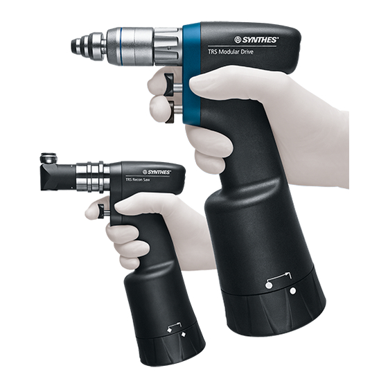
Trauma Recon System (TRS).
Battery-driven Power System designed
for traumatology and arthroplasty.
Instructions for Use
Related Manuals for Synthes TRS
Summary of Contents for Synthes TRS
-
Page 1
Trauma Recon System (TRS). Battery-driven Power System designed for traumatology and arthroplasty. Instructions for Use… -
Page 2: Table Of Contents
TRS Battery Modular Power Tool – Handpiece (05.001.201) – Lid (05.001.231) – Power module (05.001.202) Functions of the Lid for TRS Battery Modular – Mode switch Attachments for TRS Battery Modular – Important notes – Color marking on the attachments –…
-
Page 3
Power Tool – Handpiece (05.001.240) – Lid (05.001.241) – Power module (05.001.202) Functions of the Lid for TRS Recon Sagittal Saw – Mode switch Working with the TRS Recon Sagittal Saw – Starting the TRS Recon Sagittal Saw – Positioning the saw head –… -
Page 4
– TRS Battery Modular – TRS Recon Sagittal Saw – Battery Environmental Conditions Applicable Standards Electromagnetic Compatibility Accompanying documents in accordance with EN /IEC 60601-1-2, clause 5.2.2 Explanation of Symbols Used Ordering Information Synthes Trauma Recon System Instructions for Use… -
Page 5: Introduction
– The power module may never be sterilized, washed, nance”. Compliance with these specifications can consider- rinsed or dropped. This would destroy the power module ably extend the service life of the tool. Only use Synthes oil with possible secondary damage. to lubricate the tool.
-
Page 6: Accessories/Scope Of Delivery
Storage and transport Please use the original packaging for dispatch and transport. If this is no longer available, please contact the Synthes office. The same environmental conditions apply for transport as for storage, see page 57.
-
Page 7: General Information On Power Tools
2 Charge status display 3 Service indicator (when LED illuminates the power module must immediately be sent to the nearest Synthes service center) 4 Lever to remove the power module from the handpiece Trauma Recon System Instructions for Use…
-
Page 8: Starting The System
LOCK (Fig. 3 on the next page). 6. The desired mode can now be selected. Please find detailed information about the different modes in the chapters “TRS Battery Modular” and “TRS Recon Sagittal Saw”. Fig. 5 Fig. 6 Synthes Trauma Recon System Instructions for Use…
-
Page 9
If the power module does not function properly after the self-test has been carried out, it needs to be sent in to be Fig. 3 repaired. Trauma Recon System Instructions for Use Synthes… -
Page 10: Removing The Power Module
Caution: The power tool has to be kept upright (Fig. 2) so that the Power Module does not drop to the floor. Fig. 1 Fig. 2 Synthes Trauma Recon System Instructions for Use…
-
Page 11: Available Battery Capacity
– Do not use a faulty power module (service indicator illumi- nates). It should be sent in to the nearest Synthes service center for servicing. – To ensure aseptic conditions, the power module must not be removed from the handpiece until the end of surgery.
-
Page 12: Charging And Storing The Power Module
LED. For further information on the battery charger please consult the relevant instructions for use or your local Synthes office. Caution Do not –…
-
Page 13: State Of Charge And Service Indicator
The indicator lamp goes out after a few seconds to save the battery. Fig. 2 – If the service indicator does not illuminate this does not necessarily mean that the power module is fully func- tional. Trauma Recon System Instructions for Use Synthes…
-
Page 14: Cleaning, Care And Maintenance
Detailed cleaning instructions can be found from tears, cracks, etc. Damaged power modules must not be page 37 forward. used and have to be sent to the Synthes service center to be repaired. 2. Press the information button briefly to check the state of charge and the service indicator.
-
Page 15: Trs Battery Modular
TRS Battery Modular Power Tool Handpiece (05.001.201) 1 Release sleeve for attachment 2 Trigger for speed regulation 3 Trigger for switching to reverse (DRILL / REAM mode) or to oscillating drilling (OSC DRILL mode); the trigger has no function in the SAW mode.
-
Page 16: Power Module (05.001.202)
2 Charge status display 3 Service indicator (when LED illuminates the power module immediately must be sent to the nearest Synthes service center) 4 Lever to remove the power module from the handpiece Synthes Trauma Recon System Instructions for Use…
-
Page 17: Functions Of The Lid For Trs Battery Modular
Functions of the Lid for TRS Battery Modular Mode switch The mode switch on the lid for TRS Battery Modular (05.001.231) can be set to 5 different positions. 1 UNLOCK position 2 LOCK position 3 DRILL / REAM position 4 SAW position 5 OSC DRILL position The lid for TRS Battery Modular (05.001.231) only fits onto…
-
Page 18
The bottom trigger gradually controls the speed. The top trigger has no function in SAW mode, i.e. there is no effect if the top trigger is pressed. When the bottom trigger is released, the tool immediately stops. Synthes Trauma Recon System Instructions for Use… -
Page 19: Attachments For Trs Battery Modular
– After inserting a cutting tool, always check that it is properly seated by pulling it. – Only use original Synthes attachments and cutting tools. – Damage that arises from using attachments and cutting tools by other manufacturers is not covered by the warranty.
-
Page 20: Mounting The Attachments
Before working on the patient again, ensure that the correct mode has been selected, e.g. by operating the device in the air. Caution: Do not operate the mode switch when the device is running. Fig. 3 Synthes Trauma Recon System Instructions for Use…
-
Page 21: Removing The Attachments
Place the released attachment aside. Caution: To avoid injuries, the mode switch has to be in LOCK position when inserting / removing attachments or cutting tools and when placing the tool down. Fig. 4 Trauma Recon System Instructions for Use Synthes…
-
Page 22: Rotating Attachments
(Fig. 3). Insert / remove the cutting tool. Lock the chuck by turning the two moving parts counter- clockwise and tighten the chuck with the key. Synthes Trauma Recon System Instructions for Use…
-
Page 23
Caution: The attachment for acetabular and medullary reaming allows reverse mode. Only use reverse mode with tools that are approved for such use. The tool could other- wise break with consequential damage. Fig. 4 Trauma Recon System Instructions for Use Synthes… -
Page 24: Quick Couplings For Cutting Tools
Screws with a large diameter may not be able to be inserted with the AO / ASIF Quick Coupling as the torque may not suffice. Synthes Trauma Recon System Instructions for Use…
-
Page 25
(Fig. 1). These instructions apply for all attachments on this page. Caution: The Synthes warranty does not cover the function and results from using tools from other manufacturers. Trauma Recon System Instructions for Use… -
Page 26: Saw Attachments
Instructions for handling saw blades For best results, Synthes recommends using a new saw blade for each operation. This ensures that the saw blade is optimally sharp and clean. The following risks are associated with used blades: –…
-
Page 27
Deflection: approx. 4.5° (approx. 2.25° on each side) Changing the saw blades Only use original Synthes saw blades. These are optimized to meet the specific requirements of the tool. Generic products can considerably reduce the life time of the system. -
Page 28
Deflection: approx. 4.5° (approx. 2.25° on each side) Changing the saw blades Only use original Synthes saw blades. These are optimized to meet the specific requirements of the tool. Generic products Fig. 1 can considerably reduce the life time of the system. -
Page 29
11,000 osc / min Stroke: approx. 4 mm Changing the saw blades Only use original Synthes saw blades. These are optimized to meet the specific requirements of the tool. Generic products can considerably reduce the life time of the system. Fig. 1 1. -
Page 30
Slide the drive unit and coupling over the Kirschner wire. Grasp the wire by pulling the lever toward the handpiece and press both triggers (reverse) simultaneously to remove the wire from the bone. Fig. 3 Synthes Trauma Recon System Instructions for Use… -
Page 31: Radiolucent Drive
– Grip the coupled Radiolucent Drive tightly when the tool is held downward. – Only special 3-flute spiral drill bits can be used. Your Synthes representative will provide you with additional drill bit information. – Handle the Radiolucent Drive with great care. Do not al- Fig.
-
Page 32
(Fig. 3). The target rings also assist centring. The locking hole can now be drilled directly. Fig. 1 Fig. 2 Fig. 3 Synthes Trauma Recon System Instructions for Use… -
Page 33: Torque Limiters
– Observe the recommended torque of the screw. – The Torque Limiters must be annually serviced and recali- brated by Synthes. Observe the information on the test certificate in the packaging. The user is responsible for following the calibration schedule.
-
Page 34: Trs Recon Sagittal Saw
1 Mode switch 2 Safety button for mode switch (prevents inad vertent open- ing of the lid; only press to set to UNLOCK 3 UNLOCK position 4 LOCK position 5 SAW position Fig. 2 Synthes Trauma Recon System Instructions for Use…
-
Page 35: Power Module (05.001.202)
2 Charge status display 3 Service indicator (when LED illuminates the power module immediately must be sent to the nearest Synthes service center) 4 Lever to remove the power module from the handpiece Trauma Recon System Instructions for Use…
-
Page 36: Functions Of The Lid For Trs Recon Sagittal Saw
TRS Recon Sagittal Saw Functions of the Lid for TRS Recon Sagittal Saw Mode switch The mode switch on the lid for TRS Recon Sagittal Saw (05.001.241) can be set to 3 different positions. 1 UNLOCK position 2 LOCK position 3 SAW position The lid for TRS Recon Sagittal Saw (05.001.241) only fits…
-
Page 37: Working With The Trs Recon Sagittal Saw
Working with the TRS Recon Sagittal Saw Operating the TRS Recon Sagittal Saw Turn the mode switch to the SAW position. The single vari- able-speed trigger allows control of the oscillating frequency. When the trigger is released, the tool immediately stops.
-
Page 38: Changing The Saw Blades
TRS Recon Sagittal Saw Changing the saw blades Only use original Synthes saw blades. These are optimized to meet the specific requirements of the tool. Generic products can considerably reduce the life time of the system. 1. LOCK the machine.
-
Page 39: Care And Maintenance
The clinical processing instructions provided have been vali- dated by Synthes for preparing a non-sterile Synthes medical Synthes recommends annual servicing and inspection by the device; this instruction is provided in accordance with ISO original manufacturer or its exclusive sales outlets.
-
Page 40: Preparation Prior To Cleaning
Exception: Screw coupling of TRS Recon Sagittal Saw (05.001.240) and Sagittal Saw Attachment long for TRS Battery Modular (05.001.224) need to be removed for separate cleaning. Power tools and attachments may be processed using a) manual cleaning or b) automated cleaning with manual pre-cleaning.
-
Page 41: Manual Cleaning Instruction
Rinse with tap water Rinse device with cold tap water for a minimum of 2 minutes. Use a syringe, pipette or water jet to flush lumens, channels and other hard to reach areas. Trauma Recon System Instructions for Use Synthes…
-
Page 42: Clean With Detergent
Manipulate all moving parts under running water. Use a soft- bristled brush and / or soft lint-free cloth to remove all visible soil and debris. Clean screw coupling for TRS Recon Sagittal Saw (05.001.240) and Sagittal Saw Attachment long for TRS Battery Modular (05.001.224) ultrasonically for a minimum of 15 minutes at 40°C.
-
Page 43: Finale Rinse With De-Ionized/Purified Water
Finale rinse with de-ionized/purified water Finale rinse with de-ionized or purified water for a minimum of 2 minutes. Dry device using a soft lint-free cloth or clean compressed air. Trauma Recon System Instructions for Use Synthes…
-
Page 44: Mechanical /Automated Cleaning Instruction
– Alternative cleaning/disinfection procedures other than in the procedure described below (including manual pre- cleaning) have not been validated by Synthes. Remove debris Rinse device under running cold tap water for a minimum of 2 minutes.
-
Page 45: Clean With Detergent
Manipulate all moving parts under running water. Use a soft- bristled brush and/or soft lint-free cloth to remove all visible soil and debris. Clean screw coupling for TRS Recon Sagittal Saw (05.001.240) and Sagittal Saw Attachment long for TRS Battery Modular (05.001.224) ultrasonically for a minimum of 15 minutes at 40°C.
-
Page 46: Load Washing Basket
Mechanical cleaning/disinfection is an additional stress for power equipment, especially for seals and bearings. Espe- cially check sealings in the TRS lids 05.001.231 and 05.001.241 for damage after cleaning. Devices must be properly lubricated and regularly send to be serviced (at least once per year).
-
Page 47: Lubrication
Synthes special oil (519.970) and distribute the oil by moving the components. Wipe off excess oil with a cloth. The following individual parts must be lubricated: For detailed information please refer to the TRS Care and Maintenance Poster (038.000.010) Handpieces and lids –…
-
Page 48: Care And Maintenance
Storage Put cleaned, dry products into the proper places in the Storage conditions for products labeled “STERILE” are Synthes case or washing basket. Additionally, use an appro- printed on the packaging label. priate sterilization wrap or re-usable rigid container system…
-
Page 49: Repairs And Technical Service
Repairs and Technical Service The tool should be sent to the Synthes office for repair if it is faulty or malfunctions. If a device drops, it has to be sent in for service. Faulty devices may not be used. If it is no longer possible or feasible to repair the tool it should be disposed of, cf.
-
Page 50: Disposal
Please send tools that are no longer used to the local Synthes representative. This ensures that they are disposed of in accordance with the national application of the respective directive.
-
Page 51: Handpiece And Lid
The trigger is blocked by deposits Press trigger several times; clean and releasing the trigger. of blood, etc. oil according to instructions. Use only Synthes Special Oil (519.970). The power module is defective. Send power module to Synthes service center. Machine noticeably heats up.
-
Page 52
The wrong attachment is used Change attachment. (e.g. an attachment with reaming speed instead of drilling speed). TRS Battery Modular saws too fast / too Wrong mode set (DRILL / REAM instead Set correct mode (SAW) for saw attach- aggressively. -
Page 53
Check the form of the power module and the handpiece. Power module cannot be removed Power module is jammed in the Send machine to your Synthes service from the handpiece. handpiece. center. Trauma Recon System Instructions for Use… -
Page 54: Power Module
Power module casing is visibly faulty. The power module was exposed to Send power module to Synthes service excessively high temperatures. center. The power module was dropped. Send power module to Synthes service center. Synthes Trauma Recon System Instructions for Use…
-
Page 55: Attachments And Cutting Tools
The attachment or cutting tool is Replace the attachment or cutting tool, not be coupled to an attachment. deformed from wear. or send it to a Synthes service center. Attachment noticeably heats up. Attachment was under great strain. Allow attachment to cool.
-
Page 56
The cutting tool is blunt. Replace the cutting tool. surgery. For troubleshooting for the Universal Battery Charger II please consult the relevant instructions for use. If the recommended solutions do not work, please contact your Synthes affiliate. Synthes Trauma Recon System Instructions for Use… -
Page 57: Duty Cycle
Kirschner wire setting Reaming 30 sec 60 sec Sawing 30 sec 60 sec TRS Recon Sagittal Saw Cycles Sawing 60 sec 240 sec These recommendations for durations of use for the attach- ments for the Trauma Recon System have been determined under average load with an ambient air temperature of 20°C…
-
Page 58: Machine Specifications
BF, EN 60601-1 Degree of protection IPX4, EN 60529 Power supply Internally powered Battery Type Li-Ion Operating voltage (normal) 25.2 V Capacity 1.2 Ah Typical charging time <60 min Technical data is subject to tolerances. Synthes Trauma Recon System Instructions for Use…
-
Page 59: Environmental Conditions
Environmental Conditions Operation Transportation Storage Temperature 40°C 55°C 40°C –29 –29 Relative humidity Atmospheric pressure 1060 hPA 1060 hPA 1060 hPA Caution: The machine must not be stored or operated in explosive atmospheres. Trauma Recon System Instructions for Use Synthes…
-
Page 60: Applicable Standards
IEC 60601-1, 2nd Edition UL 60601-1, 1st Edition Trauma Recon System With respect to electrical shock, fire and mechanical hazards only in accordance with UL 60601-1 / CAN / CSA C22.2 No. 601.1 10PB Synthes Trauma Recon System Instructions for Use…
-
Page 61
2 h 32 min 05.002.105 Reciprocating Saw Saw blade Attachment 511.905 05.001.225 Saw blade 3 h 11 min 511.912 TRS Recon Sagittal Saw – > 8 h 05.001.240 Saw blade 519.115 Saw blade – > 8 h 519.170 Saw blade 5 h 3 min 05.002.105… -
Page 62
Handpiece 05.001.201 with Sagittal Saw Attachment, long 05.001.224 in SAW mode with 11,000 rpm Handpiece 05.001.201 with Reciprocating Saw Attachment 05.001.225 in SAW mode with 11,000 rpm Handpiece 05.001.240 in SAW mode with 11,000 rpm Technical data is subjet to tolerances. Synthes Trauma Recon System Instructions for Use… -
Page 63: Electromagnetic Compatibility Accompanying
Guidelines and manufacturer’s declaration – electromagnetic emissions The Synthes TRS handpiece is intended for use in the electromagnetic environment specified below. The customer or the user of the Synthes TRS handpiece should assure that it is used in such an environment.
-
Page 64
Guidelines and manufacturer’s declaration – electromagnetic immunity The Synthes TRS handpiece is intended for use in the electromagnetic environment specified below. The customer or the user of the Synthes TRS handpiece should assure that it is used in such an environment. -
Page 65
TV broadcast cannot be predicted theoretically with accuracy. To assess the electromagnetic environment due to fixed RF transmitters, an electromagnetic site survey should be considered. If the measured field strength in the location in which the Synthes TRS handpiece is used exceeds the applicable RF compliance level above, the Synthes TRS handpiece should be observed to verify normal operation. -
Page 66
Synthes TRS handpiece The Synthes TRS handpiece is intended for use in the electromagnetic environment in which radiated RF disturbances are con- trolled. The customer or the user of the Synthes TRS handpiece can help prevent electromagnetic interference by maintaining a minimum distance between portable and mobile RF communications equipment (transmitters) and the Synthes TRS hand- piece as recommended below, according to the maximum output power of the communication equipment. -
Page 67
UL 60601-1 / CAN / CSA C22.2 No. 601.1 10PB The device meets the requirements of directive 93/42/EEC for medical devices. It is authorized 0123 by an independent named site for which it bears the CE symbol. Trauma Recon System Instructions for Use Synthes… -
Page 68
100, calibrated 05.002.302 05.002.302S 19–12.5 1.19 511.433 511.433S 05.002.303 05.002.303S 19–12.5 1.27 05.002.304 05.002.304S 19–12.5 1.37 **Saw blade to be used with top of sternum 511.904 05.002.305 05.002.305S 19–12.5 1.47 **Teeth on both sides Synthes Trauma Recon System Instructions for Use… -
Page 69
Universal Battery Charger II 516.101 Cleaning brush 05.001.202 Power Module, for Trauma Recon System 519.970 Oil Dispenser with Synthes Special Oil, 50 ml 05.001.203 Sterile Cover, for Trauma Recon System 05.001.229 T-Handle for fixing of saw blades Trauma Recon System Instructions for Use… -
Page 70
Washing Basket, Full Size 1/1, for Trauma Recon System 68.001.602 Lid for Washing Basket, Full Size 1/1 68.001.603 Washing Basket, size 1/2, for Trauma Recon System 68.001.604 Lid for Washing Basket, size 1/2 Synthes Trauma Recon System Instructions for Use… -
Page 72
Ö036.000.505öAC0ä All technique guides are available as PDF files at 0123 www.synthes.com/lit…
Время на прочтение
3 мин
Количество просмотров 104K
Совершая уборку в деревне на недавних выходных, нашел в залежах чердака гордое творение советских инженеров электроники — “Игровой компьютер “Синтез 2”.

Без лишних мыслей было решено немедленно вывезти его из этого дикого места и посмотреть на что он способен в работе. Кому интересен процесс запуска такой старины и дополнительные кликабельные фотографии — прошу под кат.
Немного теории
Серия компьютеров «Синтез» (да-да, их было несколько, но об этом позже) — ни что иное как очередной клон компьютеров ZX Spectrum на базе чипа Z80A с тактовой частотой 3,5МГц. Выпускался, в зависимости от версии, с 128 или, как было в нашем случае, 48 КБ ОЗУ и 16КБ ПЗУ. Поддерживал цветное изображение в формате RGB, отображая 8 цветов с разрешением 256х192 Комплектовался, помимо инструкции по эксплуатации и небольшого справочника по встроенному Basic’у блоком питания, который преобразовывал 220В переменного тока в 5В 1А постоянного, набором кабелей для подключения к магнитофону и телевизору и, в зависимости от комплектации, джойстиками.
Осмотрим компьютер со всех сторон
Задняя панель. Слева направо: Гнездо блока питания, гнездо для подключения ТВ, кнопка “Reset”, гнезда для подключения магнитофона и джойстиков.

Табличка на нижней панели:

«Под капотом»:

Подготовка к запуску
Но, все же, вернемся к основной цели — запустить компьютер.
Включаем блок питания в розетку, блок питания подключаем к компьютеру. На передней панели загорелся светодиод. Питание есть — дает надежду что ПК работает. Однако чтобы убедиться наверняка надо бы его подключить как минимум к телевизору. Провода с пятиштырьковой (для магнитофона) и семиштырьковой (для ТВ) вилками сейчас воткнуть практически некуда, поэтому в гугле была найдена страничка, где были приведены схемы распайки видеокабеля на SCART и аудиокабеля на два обычных 3,5 Jack’а.
Сразу оговорюсь — когда я спаял все по инструкции оттуда, не заработало ровным счетом ничего: изображение представляло из себя белые полосы вдоль экрана, а из динамиков телевизора доносилось неприятное хрипение. Не теряя надежды ищем исходную схему компьютера, глядя на которую видно что назначения пинов гнезд ТВ и магнитофона отличаются от приведенных на сайте. Что ж, видимо у нас другая модификация.
Принципиальная схема компьютера «Синтез»

Не вдаваясь в подробности приведу модифицированную схему перепайки на SCART и на Jack кабелей для конкретно этой модификации:
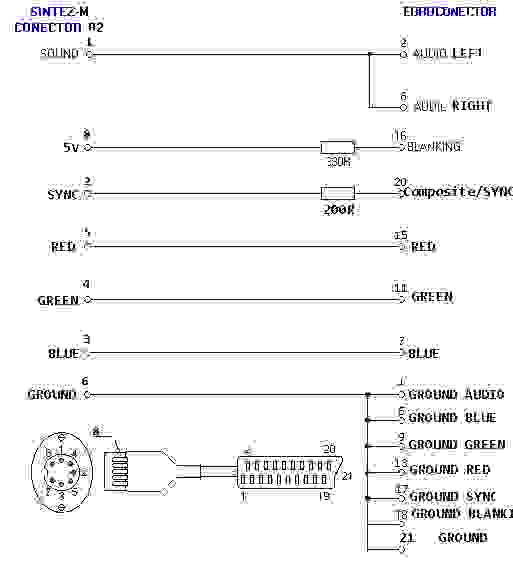

Хочу обратить внимание на сопротивление в 200 Ом на канале синхронизации, отклонение даже на 100 ОМ от этого номинала приводило к потере цветности изображения.
Давайте его запустим!
Убедившись что все работает — попробуем загрузить какую-то классическую игрушку. Поскольку кассетника, а тем более кассет с программами для спектрума в наличии не было — в качестве источника звука с игрой взяли нетбук и софтину для воспроизведения *.tap файлов — winTZX.

Выглядело это очень иронично — компьютер 1993 года выпуска загружает ПО с компьютера, в тысячи раз мощнее его. Вводим всем знакомое LOAD “”, жмем “Enter”, включаем воспроизведение… а впрочем кому интересен процесс — вот видео с загрузкой и небольшим летсплеем в старый добрый Space Raiders:
Заключение
Удивительно, но компьютер поддерживает полностью рабочее состояние по сей день. Клавиатура довольно сильно износилась, клавиши нажимаются практически без усилия, но ведь работает!
Запустив еще несколько игрушек мы закончили нашу работу с этим ПК. Теперь его место — в музее.
Напоследок — еще одно фото экрана загрузки:

Такой вот он — отечественный Spectrum.
Благодарю за внимание.