Вы можете бесплатно скачать инструкции в PDF для Cub Cadet Снегоуборщики.
У нас есть 41 бесплатных инструкций в PDF для 39 Cub Cadet Снегоуборщики.
-
1
-
2
-
3
-
4
-
5
-
6
-
7
-
8
-
9
-
b
-
s
-
t
-
w
-
Contents
-
Table of Contents
-
Troubleshooting
-
Bookmarks
Quick Links
Safety • Assembly • Operation • Adjustments • Maintenance • Troubleshooting • Parts Lists • Warranty
OPERATOR’S MANUAL
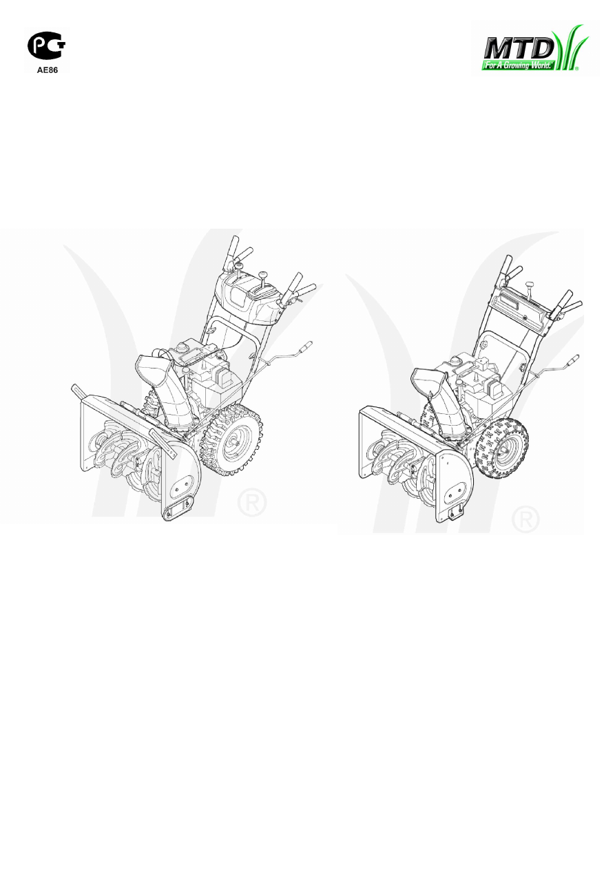
28″, 30″, 33″ & 45″Two-Stage Snow Throwers
IMPORTANT:
READ SAFETY RULES AND
INSTRUCTIONS CAREFULLY
BEFORE OPERATION
60 Ottawa Street South, KITCHENER, ONTARIO N2G 4J1
PRINTED IN U.S.A.
769-04103
06/10/08
Related Manuals for Cub Cadet OEM-390-679
Summary of Contents for Cub Cadet OEM-390-679
-
Page 1
Safety • Assembly • Operation • Adjustments • Maintenance • Troubleshooting • Parts Lists • Warranty OPERATOR’S MANUAL 28”, 30”, 33” & 45”Two-Stage Snow Throwers IMPORTANT: READ SAFETY RULES AND INSTRUCTIONS CAREFULLY BEFORE OPERATION 60 Ottawa Street South, KITCHENER, ONTARIO N2G 4J1 PRINTED IN U.S.A. -
Page 2: Table Of Contents
This Operator’s Manual is an important part of your new snow thrower. It will help you assemble, prepare and maintain the unit for best performance. Please read and understand what it says. Safety Symbols… 3 Safe Operation Practices … 4 Setting Up Your Snow Thrower …
-
Page 3: Safety Symbols
This page depicts and describes safety symbols that may appear on this product. Read, understand, and follow all instructions on the machine before attempting to assemble and operate. Symbol READ THE OPERATOR’S MANUAL(S) Read, understand, and follow all instructions in the manual(s) before attempting to assemble and operate.
-
Page 4: Safe Operation Practices
DANGER: This machine was built to be operated according to the safe operation practices in this manual. As with any type of power equipment, carelessness or error on the part of the operator can Safe result in serious injury. This machine is capable of amputating hands and feet and throwing objects. Failure to observe the following safety instructions could result in serious injury or death.
-
Page 5
Operation 1. Do not put hands or feet near rotating parts, in the auger/ impeller housing or chute assembly. Contact with the rotating parts can amputate hands and feet. 2. The auger/impeller control lever is a safety device. Never bypass its operation. Doing so makes the machine unsafe and may cause personal injury. -
Page 6: Setting Up Your Snow Thrower
Setting Up Your Snow Thrower NOTE: This Operator’s Manual covers several models. Snowthrower featrues vary by model. Not all features refer- enced in this manual are applicable to all snowthrower models. NOTE: References to right or left side of the snow thrower are deter- mined from behind the unit in the operating…
-
Page 7
Figure 3-4 Attaching the Chute Assembly • Remove locknuts and screws securing one of the flange keepers to the chute assembly. See Figure 3-4. • Loosen but do not remove the locknuts and screws on the other two flange keepers. •… -
Page 8: Final Adjustments
Snowthrower Model Drift Cutter Kit: All models OEM-390-679 Clean-Out Tool The clean-out tool is mounted to the rear of the auger housing and is designed to clear a clogged chute. See Figure 3-10. Refer to the Operation section for more detailed information regarding the chute clean-out tool.
-
Page 9
Auger Drive Figure 3-11 • Loosen the Nylock nut on the drive control cable and unthread the cable one full turn. See Figure 3-13. • Recheck adjustment. • Retighten the Nylock nut to secure the cable when correct adjustment is reached. NOTE: For more details, refer to Drive Control Adjust- ment in the Adjustment Section of this manual. -
Page 10: Operating Your Snow Thrower
Operating Your Snow Thrower WARNING Read, understand, and follow all instruc- tions and warnings on the machine and in this manual before operating. Now that you have set up your snow thrower for opera- tion, get acquainted with its controls and features. These Use extreme care are described below and illustrated on this page.
-
Page 11
Auger Control The auger control is located on the left handle. Squeeze the auger control to engage the augers. Release to stop the snow throwing action. The drive control must also be released in order to stop auger. Drive Control / Auger Control Lock The drive control is located on the right handle. -
Page 12: Starting The Engine
Service the engine with gasoline and oil as instructed in the separate engine manual packed with your unit. Read instructions carefully. Starting The Engine Operating 1. Make certain both the auger control and drive control are in the disengaged (released) position. Your Snow 2.
-
Page 13: Operating Tips
Operating Tips NOTE: Allow the engine to warm up for a few minutes. The engine will not develop full power until it reaches operating temperature. WARNING: The temperature of the muffler and the surrounding areas may exceed 150° F (65° C). Avoid these areas.
-
Page 14: Makingadjustments
Making Adjustments WARNING Shift Rod If the full range of speeds (forward and reverse) cannot be achieved, refer to Figure 5-1 and adjust the shift rod as follows: Read, understand, 1. Looking underneath the handle panel, note which and follow all instruc- of the three holes in the shift lever the ferrule is tions and warnings inserted into.
-
Page 15: Skid Shoes
Skid Shoes The space between the shave plate and the ground can be adjusted by raising or lowering the skid shoes. For close snow removal, as when using on a smooth concrete or asphalt driveway, place the skid shoes in the low position.
-
Page 16: Maintaining Your Snow Thrower
Friction Wheel Maintaining Your Snow Thrower Drive Plate WARNING Shear Pin Before lubricating, repairing or inspecting, disengage all controls and stop engine. Wait until all moving parts have come to a complete stop. Remove the safety key to prevent unintended firing of the engine.
-
Page 17
2. Remove the plastic belt cover, located near the engine, by removing the three self-tapping screws that secure it. See Figure 6-4. 3. a. Loosen the bolt shown in Figure 6-5 securing the belt keeper bracket and remove the other bolt. b. -
Page 18: Drive Belt
8. Place a block of wood underneath the auger housing as shown in Figure 6-9 and separate auger housing from the frame by tilting the housing forward and pulling up the handles. 9. Block the impeller with a piece of wood to prevent if from spinning and use a 1/2”…
-
Page 19
4. Install the new belt on the pulleys in the reverse order and re-tension with the idler pulley. 5. Reassemble your unit by performing the previous steps in the opposite order. Changing Friction Wheel Rubber WARNING: Run the engine completely dry of gasoline before tipping snowthrower. -
Page 20: Off-Season Storage
If unit is to be stored over 30 days, prepare for storage as instructed in the separate engine manual packed with your snow thrower. • Clean snow thrower thoroughly. • Lubricate as instructed in the Maintenance section of this manual. Off-Season •…
-
Page 21: Trouble Shooting
Problem 1. Choke not in ON position. Engine fails to start 2. Spark plug wire disconnected. 3. Fuel tank empty or stale fuel. 4. Engine not primed. 5. Faulty spark plug. 6. Blocked fuel line. 7. Safety key not in ignition on engine. 8.
-
Page 22: Warranty
The limited warranty set forth below is given by MTD Products Limited with respect to new merchandise purchased and used in Canada and/or its territories and possessions (either entity respectively, “MTD”). MTD warrants this product (excluding its normal wear parts as described below) against defects in material and workmanship for a period of three (3) years commencing on the date of original purchase and will, at its option, repair or replace, free of charge, any part found to be defective in materials or workmanship.
-
Page 23
NOTES: For parts and/or accessories refer to customer support on page 2. Adressez-vous au «Service après-vente» à la page 2 pour ce qui concerne les pièces et/ou accessoires. -
Page 25
PART N° DE N° DE RÉF PIÈCE DE SCRIP TION 784-5604A Chute Tilt Han dle 646-0012 Ca ble Ass’y (Au ger/Drive) 684-0053B Lower Chute Crank As sem bly 705-5218 En gage Han dle RH Black 705-5219 En gage ment Han dle LH Black 705-5266 Up per Chute Crank Sup port 710-0458… -
Page 26
B&S 305-342 cc Torque to 21 ft./lbs. maximum, washer should be flat./ Serrez à un couple de 21 pi-lb maximum. La rondelle doit être plate. When rebuilding gear box fill one housing half completely with grease 838-0168./Pour remonter la boîte d’engrenages, remplissez complètement une moitié… -
Page 27
PART N° DE N° DE RÉF PIÈCE DE SCRIP TION 736-0159 Flat Washer .349 ID x .879 OD x .063 714-0104 Int. Cot ter Pin 754-0222A V-Belt 1/2 x 44″ Lg. 754-04131 V-Belt 1/2 x 42″ Lg. 736-0505 Flat Washer .34 x 1.5 x .150 720-0284 Han dle Knob As sem bly 710-1245B… -
Page 28
PART N° DE N° DE RÉF PIÈCE Au ger Shaft 738-04155 Shear Pin 5/16-18 x 1.75 618-0246 Gear Hous ing Half — RH 741-0192 Flange Bear ing 714-0126 #9 HI-Pro Key 3/16 x 3/4 Dia HT 711-04714 Au ger Drive Shaft 716-0111 Snap Ring for .875 dia. -
Page 29
PART N° DE N° DE RÉF PIÈCE DE SCRIP TION STYLE 7 629-04010A Wire Har ness 710-1003 Hex Tapp Wash Hd. Scr. #10 x 5/8 725-1658 Bulb #890, 12 V, 27 Watt 725-1672 Head light Hous ing 731-04069 Black Han dle Panel 747-1136 Re tainer 710-04187… -
Page 30
Torque to 325-550 in./lbs Serrez à un couple de 325-550 po-lb. 97 46 83 88 Torque to 325-450 in./lbs Serrez à un couple de 325-450 po-lb. -
Page 31: Parts List
PART N° DE N° DE RÉF PIÈCE DE SCRIP TION 05244B Bear ing Hous ing 618-0279 LH Dog As sem bly 618-0280 RH Dog As sem bly 618-0282E Steer ing Shaft As sem bly 618-04178 Wheel Ass’y Bear ing 6.0″ OD 718-04034 Fric tion Wheel Bonded 710-0896…
-
Page 32
PART N° DE N° DE RÉF PIÈCE 741-0563 Ball Bear ing w/snap ring 741-0748 Flange Bush ing .500 ID x .627 OD 746-0949A Steer ing Ca ble 746-0951 Au ger Idler Ca ble 747-0973 Drive Clutch Rod 750-0903B Split Spacer 1/2 x 5/8 x 2.69 750-0997 Spacer .625 ID x 1.0 OD x .23 750-1302B… -
Page 33
NOTES: For parts and/or accessories refer to customer support on page 2. Adressez-vous au «Service après-vente» à la page 2 pour ce qui concerne les pièces et/ou accessoires. -
Page 34
accessoires. et/ou pièces concerne pour page à après-vente» «Service Adressez-vous page support customer refer accessories and/or parts NOTES:… -
Page 35
05.28.08 1-800-668-1238 téléphone: garantie. honorer faire pour spécifiques juridiques droits accorde cadeau. offert été produit laquelle résultant blessure matériel dommage avenue. nulle garantie rendra d’achat prix montant supérieur votre dans s’appliquer peuvent ci-dessus immatériels accessoires dommages location frais pelouses limiter, s’y sans comprenant,… -
Page 36
cisaillement. tarière. bâton. l’outil Dégagez l’intérieur Nettoyez d’entraînement. technique. d’aération. chapeau. bougie. machine vibrations tous Serrez après-vente. service technique. adressez-vous technique. détails, plus Pour mineurs. d’entretien réservoir problèmes d’essence concerne chapitre REMARQUE: plein remplacez Dépannage propre départ”. goupille Remplacez d’entretien. Régime Voir commande… -
Page 37
silicone. légère d’huile couche roulements ressorts, chaînes, machine Enduisez rouille. contre bien aéré, métallique abri à machine remiser avant endroit dans souffleuse page à lubrification renseignements souffle- l’extérieur débris moteur. d’utilisation notice accompagne moteur d’utilisation fournies instructions selon façon jours, plus pendant entreposé… -
Page 38
souffleuse avec châssis. serrez gauche fendillements. apercevez vous d’usure signes l’apparition dès frottement roue caoutchouc bague Remplacez périodiquement. vérifiée être devrait s’user à tendance frottement roue caoutchouc bague AVERTISSEMENT hexagonal Entretien l’arbre Glissez frottement normale. fonctionnement position dans Reposez auto-taraudeuses. place châssis couvercle… -
Page 39
poulie d’entraînement courroie bas. d’entraînement poulie d’entraînement courroie doucement. tension poulie Relâchez 6-11. Voir tension. poulie courroie tension. relâcher pour d’entraînement courroie l’arrière tension poulie précédemment. fournies instructions courroie démontez fait, été encore d’entraînement: 6-11 Figure 6-10 Figure poulie Fente l’adaptateur Taquet Figure… -
Page 40
exact. modèle votre représenter peuvent seulement indicatif titre à fournies sont photos obligation. préavis sans modifiées être peuvent techniques caractéristiques usée. paraît courroie toute Remplacez souffleuse. d’utilisation heures toutes d’entraînement courroie tarières courroie l’état Vérifiez souffleuse. votre garantie couverts seront résultant composants d’autres… -
Page 41
fond. à Serrez l’intérieur trouve ordinaires boulons assurant vous neuve plate lame l’habitacle maintiennent contre-écrous ordinaires boulons plate: lame 6-3. Figure Voir niveau. être pour patins Assurez-vous précédemment. boulonnerie avec patins nouveaux souffleuse. maintiennent embase à contre-écrous échéant) plate rondelle ordinaires boulons patins:… -
Page 42
plate. lame entre maximal ment dégage- assurer pour haute plus position à patins réglez gravier, recouverte surface souffleuse utiliser devez vous quelconque, raison pour matériels. dégats corporelles blessures causer peut tarière, projeté s’il qui, gravier recouverte surface souffleuse d’utiliser déconseillé IMPORTANT: Réglages support… -
Page 43
couvre-châssis. obtenu. voulu l’ajustement câble maintenir pour contre-écrou Resserrez besoin. selon câble dévissez vissez l’entraînement câble contre-écrou Desserrez suivant l’ajustement faites Sinon, 5-3. Figure d’entraînement. plaque touche frottement vérifiez l’entraînement, commande 5-3. Figure Voir vitesses. levier toutes à d’entraînement, plaque roue entre d’espace… -
Page 44
système. frottement roue prématuré l’usage causera Ceci roues. l’entraînement l’embrayage lâché d’abord avoir sans vitesses levier JAMAIS déplacez IMPORTANT souffleuse. mieux connaissiez vous jusqu’à lentes plus vitesses vous Servez- REMARQUE: boulonnerie souffleuse. ajustements notice entretenir toucher. bénéficier Évitez (65°C). d’une 150°F dépasser peut… -
Page 45
normale. fonctionnement température lorsqu’il puissance toute développe quelques pendant tourner moteur Laissez VOLET. SANS position à lentement PLEIN, VOLET position à départ volet nouveau à tournez hésite, moteur SANS position vers départ volet bouton lente- tournez chauffe, moteur mesure retenant. tout lentement s’enrouler… -
Page 46
souffleuse. moteur mouvement pièces toutes ajustés vêtements cheveux pieds, mains, toujours Éloignez mortel. inodore carbone, monoxyde contiennent moteur d’échappement ventilé. clos local dans l’intérieur à moteur tourner jamais faites utilisation. pendant démarrage lors souffleuse proximité à tient personne Assurez-vous espaces souffleuse. -
Page 47
moteur. marche pour » « position doit moteur arrêter bascule à Interrupteur l’équipement. autorisée utilisation éviter pour sécurité clé Enlevez démarre. pour enfoncée bien être doit sécurité sécurité remplissage. goulot moteur à d’huile niveau vérifier d’huile froid. temps moteur démarrer à… -
Page 48
selon réduisez recommandée avant l’expédition. pneuma- chapitre recouvertes abais- irrégulière. sera raclage plaque l’usure l’autre plus sup- instructions côté d’un tirer risque machine pneus, tous dans égale raccrochez n’est pression complets IMPORTANT main. à goulotte dans tarière près glace neige jamais dégagez AVERTISSEMENT… -
Page 49
3-13. Figure Voir complet. tour dévissez l’entraînement commande câble trouve contre-écrou suit l’entraînement commande ajustez débrayée, l’entraînement commande alors machine déplacer essayez vous position à position déplacé levier quand mouvement résiste précédents. tests deux répétez (R2) marche position à vitesses levier résistance. -
Page 50
correctement. risque sans fonctionne souffleuse votre vérifier pour ajustements tous effectuez instructions soigneusement suivez Lisez page à tarière» «Commande à référez-vous souffleuse, votre d’utiliser Avant AVERTISSEMENT montage Instructions Figure câbles tige inférieure. Figure dents partie manivelle souffleuse. orientant maintiennent Figure 3-7. -
Page 51
précédemment. fendue goupille avec place Maintenez Figure Voir manivelles. trous Figure Voir travail. dans aider peut pinces inférieure. manivelle dans supérieure Enfoncez goulotte. supérieure l’extrémité fendue goupille goulotte manivelle fermement. guidons fixez trous place déjà boutons précédemment. enlevés ordinaires boulons rondelles avec inférieur… -
Page 52
machine. notice cette dans figurent instructions ments avertisse- respecter comprendre lire, peuvent personnes utilisée être doit machine Cette 06.09.08 responsabilité Votre SYMBOLE! recomman- sont ACCOMPAGNE dispositifs L’AVERTISSEMENT sta- machine RESPECTEZ fonctionnement. utile corporelles. américaine blessures entraîner “U.S. peut instructions Com- non-respect machine. -
Page 53
état. sont qu’ils assurez-vous place sécurité dispositifs tous Laissez elle d’éjection goulotte sans jamais relâchées. sont lorsqu’elles débrayage automatiquement revenir directions deux dans fonctionner doivent commande manettes corporelles. blessures machine l’emploi dangereux rendrait jamais contournez sécurité. dispositif tarière l’ensemble commande pieds. -
Page 54
machine. notice cette dans figurent instructions ments avertisse- respecter comprendre lire, peuvent personnes utilisée être doit machine Cette responsabilité Votre SYMBOLE! ACCOMPAGNE L’AVERTISSEMENT RESPECTEZ corporelles. blessures entraîner peut instructions carbone, non-respect bâtiment machine. cette servir vous d’essayer avant d’utilisation notice cette dans figurant… -
Page 55
votre poursuivre pouvoir déterminer pour précédent dans soit fabricant, fonction nominale, puissance performance, après- service choisissez utiles, ci-dessous: options l’une Choisissez commandes, concernant après-vente. vendue, l’a vous modèle notice cette anglaise page (voir saison attentivement lire donc renseignements fournit vous avant série numéro… -
Page 56
06/10/08 769-04103 D’UTILISATION Entretien ONTARIO KITCHENER, South, MACHINE. AVANT INSTRUCTIONS RÉGLES phases Garantie détachées pièces Réglages Fonctionnement ÉTATS-UNIS Street Ottawa MARCHE ATTENTIVEMENT deux à neige à Souffleuses NOTICE Listes Dépannage Assemblage Sécurité IMPRIMÉ METTRE SÉCURITÉ LISEZ IMPORTANT:…

-
Contents
-
Table of Contents
-
Troubleshooting
-
Bookmarks
Quick Links
Safe Operation Practices • Set-Up • Operation • Maintenance • Service • Troubleshooting • Warranty
O
‘
M
peratOr
s
anual
Two Stage Snow Thrower — Model 945 SWE
WARNING
READ AND FOLLOW ALL SAFETY RULES AND INSTRUCTIONS IN THIS MANUAL
BEFORE ATTEMPTING TO OPERATE THIS MACHINE.
FAILURE TO COMPLY WITH THESE INSTRUCTIONS MAY RESULT IN PERSONAL INJURY.
CUB CADET LLC, P.O. BOX 361131 CLEVELAND, OHIO 44136-0019
Printed In USA
FORM NO. 769-09711
(March 26, 2014)
Summary of Contents for Cub Cadet 945 SWE
На этой странице вы можете совершенно бесплатно скачать Руководство по эксплуатации Cub Cadet 945 SWE.
У документа PDF Руководство по эксплуатации 28 страниц, а его размер составляет 2.91 Mb.
Читать онлайн Снегоуборщики Cub Cadet 945 SWE Руководство по эксплуатации

Скачать файл PDF «Cub Cadet 945 SWE Руководство по эксплуатации» (2.91 Mb)
Популярность:
4865 просмотры
Подсчет страниц:
28 страницы
Тип файла:
Размер файла:
2.91 Mb

Прочие инструкции Cub Cadet Снегоуборщики


Прочие инструкции Cub Cadet


Не Включается
Шумит Мотор
Не Работает Зажигание
При Включении Привода Колес Двигается Очень Медленно На Любой Скорости. На Средних Оборотах Двигателя Почти Не Едет.
Неровная Работа Двигателя
Плавает Подпружиненая Заслонка Карбюратора
Газы Выхлопные В Картери Двигателя
Слабо Выкидывает Снег
При Включении Шнека Стоит Визг
Порвался Ремень Привода Шнека
Не Работает Задняя Скорость
На Патриоте Одна Из Задних Скоростей Не Работает, На Другой Задней Едет Очень Медленно. Всего-Навсего Поднял Ручки Вверх Для Удобства.
Упали Обороты Двигателя
Обороты Значительно Ниже Отлаженных На Заводе
Порвалась Гусеница
Порвалась Гусеница
Лопнул Шкив Привода Шнека
Где Купить
Mst 2000
Развалился Подшипник Электродвигателя
Развалился Подшипник Электродвигателя На M S T 2000
Обьем Масла В Кпп
Утечка Топлива
Залил Полный Бак, Минут Двадцать Поработал, Заглох. Долго Не Мог Понять В Чём Дело. Оказалось Каким-То Образом Вытек Бензин Из Бака.
Двигатель Работает Не Ровно Нагар На Свечах
Клинит Шнековое Колесо В Обратную Сторону Крутитса Включаем Выброс Снега И Почти Сразу Колом Встает Аж Ремень Горит
Не Крутится Шнек, Маховик Выброса Снега Работает
Как Снять Редуктор Шнека, Открутил Весь Крепеж, А Ничего Не Распадается???
Не Нажимается Рычаг Шнека И Рычаг Поворота Влево
При Попытке Нажать На Рычаг Шнека, Чтобы Выбрасывать Снег, Ничего Не Получается, То Же Самое И С Поворотом Влевую Сторону.
Течет Бензобак
Заливается Полный Бак Бензина. Через 20 Минут Работы Бак Пуст. Как Определить Течь? На Сколько По Времени Работы Рассчитан Полный Бак Бензина?
Снегоуборщик Ps 621.
Заводится Хорошо,Работает 1-2 Минуты Затем Начинают Плавать Обороты И В Итоге Глохнет. Помогите
Сломалась Ось Привода Колес
Сломалась Ось Привода Колес (Сломалась Шестерня). Где Купить?
Течет Масло
После Замены Масла В Двигателе Начало Подтекать, Но Не Сильно. Это Третья Замена Масла.
Снегоуборщик Ксм22 Идеал Арт
Полетела Пластмассовая Шестерня Редуктора Хода.новую Не Могу Найти.желательно Бы Заменить На Металлическую.шестерня Разборная.
Експерт Ирбис 455 Снегоуборщик
При Выключенном Сцеплении Снегоуборщик Продолжает Двигаться
Краткое содержание страницы № 1
Safe Operation Practices • Set-Up • Operation • Maintenance • Service • Troubleshooting • Warranty
Otreap Or ’s Mlauna
Two Stage Snow Thrower — 945 SWE
WARNING
READ AND FOLLOW ALL SAFETY RULES AND INSTRUCTIONS IN THIS MANUAL
BEFORE ATTEMPTING TO OPERATE THIS MACHINE.
FAILURE TO COMPLY WITH THESE INSTRUCTIONS MAY RESULT IN PERSONAL INJURY.
CUB CADET LLC, P.O. BOX 361131 CLEVELAND, OHIO 44136-0019
Printed In USA FORM NO. 769-04106
(June 6, 2008)
Краткое содержание страницы № 2
To The Owner 1 Thank You Thank you for purchasing a Snow Thrower manufactured by If you have any problems or questions concerning the machine, Cub Cadet LLC. It was carefully engineered to provide excellent phone your local Cub Cadet dealer or contact us directly. Cub performance when properly operated and maintained. Cadet’s Customer Support telephone numbers, website address and mailing address can be found on this page. We want to Please read this entire manual prior to operating the eq
Краткое содержание страницы № 3
Important Safe Operation Practices 2 WARNING! This symbol points out important safety instructions which, if not followed, could endanger the personal safety and/or property of yourself and others. Read and follow all instructions in this manual before attempting to operate this machine. Failure to comply with these instructions may result in personal injury. When you see this symbol. HEED ITS WARNING! CALIFORNIA PROPOSITION 65 WARNING! Engine Exhaust, some of its constituents, and certain v
Краткое содержание страницы № 4
5. Never run an engine indoors or in a poorly ventilated area. Safe Handling of Gasoline Engine exhaust contains carbon monoxide, an odorless To avoid personal injury or property damage use extreme care and deadly gas. in handling gasoline. Gasoline is extremely flammable and the 6. Do not operate machine while under the influence of vapors are explosive. Serious personal injury can occur when alcohol or drugs. gasoline is spilled on yourself or your clothes which can ignite. Wash your
Краткое содержание страницы № 5
Maintenance & Storage Do not modify engine 1. Never tamper with safety devices. Check their proper To avoid serious injury or death, do not modify engine in any operation regularly. Refer to the maintenance and way. Tampering with the governor setting can lead to a runaway adjustment sections of this manual. engine and cause it to operate at unsafe speeds. Never tamper with factory setting of engine governor. 2. Before cleaning, repairing, or inspecting machine disengage all control levers a
Краткое содержание страницы № 6
Safety Symbols This page depicts and describes safety symbols that may appear on this product. Read, understand, and follow all instructions on the machine before attempting to assemble and operate. Symbol Description READ THE OPERATOR’S MANUAL(S) Read, understand, and follow all instructions in the manual(s) before attempting to assemble and operate WARNING— ROTATING BLADES Keep hands out of inlet and discharge openings while machine is running. There are rotating blades inside WARNING—
Краткое содержание страницы № 7
Assembly & Set-Up 3 Contents of Carton • One Snow Thrower • Two Replacement Auger Shear Pins • One Chute Assembly • One Snow Thrower Operator’s • One Briggs & Stratton Engine • One Product Registration Card Manual Operator’s Manual 4. Secure the upper handle and lower handle with the two wing Assembly nuts and carriage bolts removed earlier. Tighten the two IMPORTANT: Two replacement auger shear pins are included wing nuts already installed in the upper holes to firmly with this manual (or st
Краткое содержание страницы № 8
NOTE: If the connector is not properly assembled, the shift rod Place chute assembly onto chute base as shown in Figure 3-5. will pivot and you will not be able to change speeds or direction. Make sure that the chute notches engage with the spiral end If the full range of speeds (forward and reverse) can not be of chute directional control, and the two flange keepers are achieved, refer to the “Maintenance and Adjustments” section. beneath the flange on the chute base. Chute Directional Con
Краткое содержание страницы № 9
Set-Up Shear Pins A pair of replacement auger shear pins and bow tie cotter pins have been included with your snow thrower. Store the pins in a convenient place for use if an original equipment shear pin should break. Chute Clean-Out Tool Lower The chute clean-out tool is fastened to the top of the auger Shave housing with a mounting clip and a cable tie at the factory. Cut Plate the cable tie before operating the snow thrower. Shave Plate Tire Pressure (Pneumatic Tires) The tires ar
Краткое содержание страницы № 10
4. With the auger control in the disengaged “up” position, walk to the front of the machine. 5. Confirm that the auger has completely stopped rotating and shows NO signs of motion. If the auger shows ANY signs of rotating, immediately return to the operator’s position and shut off the engine. Wait for ALL moving parts to stop before re-adjusting the auger control. Testing Drive Control & Shift Lever 1. With the engine turned off, move the shift lever into sixth (6) position. Refer to Fig
Краткое содержание страницы № 11
Controls and Features 4 Drive Control Shift Lever Headlight Two-Way Chute Control™ Auger Control Wheel Steering Chute Control Assembly Chute Directional Control Fuel Cap Choke Primer Oil Fill Ignition Key Recoil Starter Clean-Out Tool Starter Handle Augers Button Oil Drain Skid Shoe Electric Starter Outlet Figure 4-1 Snow thrower controls and features are described below and Choke Control illustrated in Fig. 4-1. NOTE: For detailed information on all engine controls, refer to the separ
Краткое содержание страницы № 12
Primer Bulb Auger Control Pressing the primer bulb forces fuel directly into the engine’s carburetor to aid in starting a “Cold” engine. NOTE: Do not use the primer bulb to restart a warm engine after a short shutdown. Oil Fill Engine oil level can be checked and oil added through the oil fill. Skid Shoes Position the skid shoes based on surface conditions. Adjust upward for hard-packed snow. Adjust downward when operating on gravel or crushed rock surfaces. Electric Starter Outlet The auge
Краткое содержание страницы № 13
Two-Way Chute Control™ Wheel Steering Controls The two-way chute control is located on the left side of the dash The left and right wheel steering controls are located on the panel and is used to control the distance of snow discharge from underside of the handles. Squeeze the right control to turn right; the chute. squeeze the left control to turn left. • To change the upper chute angle to control the distance NOTE: Operate the snow thrower in open areas until you are that snow is thrown, p
Краткое содержание страницы № 14
Operation 5 6. When disconnecting the extension cord, always unplug the Starting The Engine end at the three-prong wall outlet before unplugging the 1. Attach spark plug wire to spark plug. Make certain the opposite end from the snow thrower. metal loop on the end of the spark plug wire (inside the Recoil Starter rubber boot) is fastened securely over the metal tip on the spark plug. 1. Rotate choke control to FULL choke position (cold engine start). 2. Make certain both the auger contro
Краткое содержание страницы № 15
To Engage Drive Operating Tips 1. Move the shift lever into one of the six forward (F) positions NOTE: Allow the engine to warm up for a few minutes. The or two reverse (R) positions. Select a speed appropriate for engine will not develop full power until it reaches operating the snow conditions and a pace you’re comfortable with. temperature. NOTE: Use slower speeds in higher snow and/or until you are WARNING! The temperature of the muffler and familiar with the snow thrower operation. the
Краткое содержание страницы № 16
Maintenance & Adjustments 6 4. With the mounting holes toward the back, slide the new Maintenance shave plate into position and secure with the fasteners Engine removed previously. Refer to the Briggs & Stratton Engine manual packed with your Lubrication machine for all engine maintenance. Gear Shaft Shave Plate and Skid Shoes The gear (hex) shaft should be lubricated at least once a season The shave plate and skid shoes on the bottom of the snow or after every twenty-five (25) hours of op
Краткое содержание страницы № 17
Auger Shaft At least once a season, one at a time, remove the shear pins from the auger shaft. Spray lubricant inside the hub of each auger spiral assembly and around the spacers on the auger shaft. Grease fittings can also be found at each end of the auger shaft. Lubricate flange bearings found at each end of the shaft with a grease gun once a season. See Figure 6-3. Gearbox Lube Fitting Shear Pin Vent Plug Lube Fitting at Each End of Auger Shaft Figure 6-4 will go to shift the drive into
Краткое содержание страницы № 18
4. If there is no friction wheel clearance, or the friction wheel does Refer to “Auger and Drive Control Cables” of the Assembly & Set-Up — not solidly contact the drive plate, re-adjust the lock nut on Section 3 for instructions to adjust the drive control. To further the lower end of the drive cable following the instructions check the adjustment, proceed as follows: in the Assembly section. 1. With the snow thrower tipped forward (be certain to drain 5. Reassemble the frame cover. gasol
Краткое содержание страницы № 19
Service 7 4. Loosen the bolt shown in Figure 7-3 securing the belt Belt Replacement keeper bracket and remove the other bolt. Push the Belt Removal Preparation belt keeper bracket up off the engine pulley. Refer to 1. Disconnect the chute crank assembly at the discharge Figure 7-3. chute end by removing the hairpin clip and the flat washer. Refer to Figure 7-1. Remove Loosen Figure 7-3 Auger Belt Replacement Figure 7-1 To remove and replace your snow thrower’s auger belt, 2. Remove the he
Краткое содержание страницы № 20
2. Slip the auger control belt (the front belt) off the engine 6. Block the impeller with a piece of wood the prevent from pulley. spinning and use a 1/2” wrench to remove the hex screw and flat washer from the center of the auger 3. Pull the brake bracket assembly towards the cable guide input shaft and auger pulley adapter. Refer to Figure roller and unhook the auger cable “Z” fitting. Refer to 7-7. Figure 7-5. Adapter Post B C Pulley Slot Belt Keeper A Figure 7-5 Figure 7-7 4. From bo
Самый мощный, надежный и высокопроизводительный, четырехколесный снегоуборщик (в приводе все четыре колеса), в России. Двигатели компании Briggs & Stratton специально разработаны для работы в тяжелых зимних условиях, оборудованы капсулой с пусковым топливом для быстрого запуска и большим глушителем для тихой работы. Усиленный зубчатый шнек X Auger, благодаря которому, обеспечивается наиболее эффективное измельчение наледи и слежавшегося снега.
Двойной цепной, управляемый привод на колеса. Дополнительная стальная, поддерживающая тяга на редуктор исключает возможность его заклинивания при больших нагрузках. Высокопроизводительный ротор с четырех лопастной крыльчаткой выброса диаметром 45 см. Обслуживаемый редуктор, и подшипники шнека для профессионального использования. Шнек, выполненный из стали большой толщины и снабженный зубцами, обеспечивает более эффективное измельчение наледи и слежавшегося снега. Шнек состоит из 2-х независимых друг от друга спиралей с увеличенной рабочей поверхностью, что обеспечивает большую производительность и позволяет продолжать работу даже при срезании “пальца” одного из шнеков. Восьмискоростной привод с фрикционным диском, гарантирует самую высокую производительность в любых условиях. Прочный пластиковый желоб для выброса снега, поворачиваемый на 190.
Джойстик для управления направлением и дальностью выброса снега. Электрозапуск значительно облегчает запуск машины даже после длительного хранения при очень низких температурах. Шины X-Trac с ярко выраженным, направленным протектором исключают возможность пробуксовки даже на обледенелых участках.
(скачивание инструкции бесплатно)
Формат файла: PDF
Доступность: Бесплатно как и все руководства на сайте. Без регистрации и SMS.
Дополнительно: Чтение инструкции онлайн
1
MTD
)
Form No. 769-01275
Страница:
(1 из 17)
навигация

1

2

3

4

5

6

7

8

9

10

11

12

13

14

15

16

17
Оглавление инструкции
- Страница 1 из 18
1 MTD ) Form No. 769-01275 - Страница 2 из 18
2 ! . , . ( – ) . , , . , , . . , , , . 1. . . : , . . 2. . . 3. 14 . 14 , . , , 4. , . 5. ( .). . , . , , . 6. , , 25 . . 7. , , . 1. , , , . , , , , , , , . , . , 2. . , , : . , . . 3. . , . . , , – . . , . 4. : , , . , , , , - Страница 3 из 18
3 , . . 5. 5. . , , , . . 6. 6. , . . 7. , 7. . , . . 8. 8. , , , . . 9. , . 10. 9. , , . , , . , . . , 11. . , . , , . a. 12. . b. , , , . . 13. c. . . d. . . . 14. e. . . f. . 15. , , , . . g. . , 16. . h. , , . . . . . . i. 17. , ( , , ( , , ) . , , .). . j. 18. . . . 1. . , , , ( . ) , . . 2. . - Страница 4 из 18
4 : 1. , . . , . . . 2. . , ( ! ) . . . ( ) , . . 1. 3. , , . , . . . . 4. , , . . , 1. 2. . . , 5. , . . . , . . 1-1, 1-2. , . . b. , , . . . 2. . , . . 6. , . 3. , . . , . . 4-6. 4. . . 7. . . 3. 5. , . . 8. . . . 4. . . , 9. . 6. , . . 10. , , , , , . 11. . . , . . , . . 1.1. . . 5. - Страница 5 из 18
5 . 4. ! . . 1.2. , . , . . « ». . 5. . , , . . 2. , . . . . 3. , : . . 6. . . . . 7. - Страница 6 из 18
6 . 7. . 10. ( . ). ( : ). , . . , ( ). . . . ! . — . . . . 8. . , . . . 1. 2. . . 11. . , «Stop». . , 3. 4. . 5. . 6. ( ), . 8. — : , , , . , . 9. , . . . 10. . 11. . 9. - Страница 7 из 18
7 : . , . . 12. . . . . . . . . . ( (F). , (1) – (6) – ) . . . . . (R). (1) , (2) . . . - Страница 8 из 18
8 . . . . . . : ( . — ). , ; . . , : . . . . . . : . . . ( ) ) . . , . . . * . . . , ( . . ) . . . . : , . , . . 220 . . , . , . . . . . . . . . . . , 220 . . . . . . - Страница 9 из 18
9 7. ( , . ), , . . 1. . FULL (« : : , »). , FULL . OFF. 2. . ( ) , , 1. . . 2. 3. , ( ) , . . . 3. FAST (« , . 4. »). . , . . . . 5. : , , OFF. . FULL . 1. , , OFF. , : . , . . . . : . . : . . 1. , , . . 120 . 2. , . 220 , . : . 1. , . , 3. , . , . 4. 2. STOP. FULL (« ). : ») ( 5. ( . , FULL 6. , - Страница 10 из 18
10 4. 9. 10. , . . . . . 1. , , . . 2. . . 3. , . . . 12. . 1. , . . 2. , , . 13. . . . : , . . 14 : . 3. 1. ; . 2. . . . . 14. 3. . . . 4. 5. . . . , . 1. , . ! , . ( ) , . 2. . , FAST (« 3. »). ( ) . 4. 10 . 14. , . . , . 5. . ( FAST (« »)) . : . 6. , — ( 1/2″, 2. ( . ), 3. . 7. , . . ( . 13. , . - Страница 11 из 18
11 UP, . . : 1. , . . 2. . . . 3. , R2 F6 . . 4. , : 5. . 15-1. . . . . 17. 6. ( . 1. ). . 7. , , . 2. . . . 15-2. . 17. : 1. ( , ), , . 15-2. . 23. , 3 , . . 3. , . , , . 2. . . , . . . . 25. 4. , . 16. . . . 17. . 5. . : , . . . , , . 16. . . 18. . . - Страница 12 из 18
12 6. : , . 7. : . 8. : , 25 . 9. : . . . 18. 1. . 2. , , , ( ) . . . 19. 3. . 4. . : , , . . . . . . . 1. 25 : , , . 20. , , . . 2. : . . . . 3. , . 25. , : . . , Shell Alvania (#737-0168). 4. . , . , : 2. . , . . . . . 5. . 20. 1. , : . . . , . . . 19. . : . . . 20. - Страница 13 из 18
13 , , . . , , . . 1. , . 2. , . , . . 22. : , , . 1. . . 9. , , . 2. . . . 23. . 21. . : . 25 . . 24. . , . 1. , . 2. , . , . 3. 4. . . , . . 5. . . . 25. . : , . - Страница 14 из 18
14 . 26. . 29. : , . , , . . : . 1. , . : , , . 2. , , . 30. . : , . 3. . , . . . . . . . 12). 4. . 5. . . 27. . 6. 7. . . . 50 . 1. , , . 2. , . , . . 28. - Страница 15 из 18
15 . , , . , . . (F3). — , . , . 1. . , . . , . . , . 32. . 31. 2. , . . . 32. 3. . , . 33. . : , . : 4. . . , . 34. — , . — . . 33. . . 34. . 31. - Страница 16 из 18
16 : . .! 30 , , . . . . : . : , , , , , . : : , , , , . 14. : . ! , , STA-BIL) ( .) , . . . , . . , , 10 , 30 . . 4. . , : 30 . , . , . . . , . , : . , . . . 1. 1. . 2. , . , . 3. , , . . 14). , , , , , . 2. . 3. « . 4. , . » - Страница 17 из 18
17 1. 1. 2. 3. . 2. 3. . . . , . . 4. 4. . . 5. 5. 6. 7. , . . . 6. 4 ( . ). . 7. , , 10 . 1. 1. . . 2. 2. 3. , . 4. 1. . . . 1. 3. 4. . . 1. . 1. . . 2. 2. . . 1. 1. , . . . . , . 1. 1. . . 2. 2. 1. . 1. . . 1. . 1. . . 2. 3. . . 2. 3. . . 4. . . . 5. 4. 5. . . . : MTD Products AG, . , . 23, . MTD - Страница 18 из 18
Инструкции и руководства похожие на CUB CADET PRO 933 SWE
Другие инструкции и руководства из категории профессиональный снегоуборщик
© 2023 manuals-help.ru, Все права защищены
Узнавай о новинках и акциях первым
Вы успешно зарегистрированы на сайте.
Вам доступен личный кабинет пользователя.
Перейти к покупкам
Ваш пароль воcстановлен!
Теперь вы можете полноценно пользоваться
всеми возможностями нашего интернет-магазина.
Здравствуйте, Ваша претензия принята и зарегистрирована.
В течение 3-х рабочих дней Вам, на электронную почту, будет дан письменный ответ. В случае возникновения дополнительных вопросов, менеджер претензионного отдела свяжется с Вами.
Перейти к покупкам

Ваше сообщение об ошибке на сайте успешно отправлено.
Большое спасибо!
Добавить отзыв о магазине
Торг для данного товара сейчас не возможен!
Сколько вы готовы заплатить за этот товар?
Введите ваше ценовое предложение
Мы согласны с вашим предложением
Мы принимаем вашу цену, и вы можете купить товар по цене:
0 руб.