- 0
- Жалоба
- 2 543
- 2
- m2010 от 30-01-2015, 14:27
Похожее
-
Руководство по материальной части и эксплуатации АСУ-57 [Воениздат]
Уставы, наставления, ТО и ИЭ -
БТР-40. Руководство по материальной части и эксплуатации бронетранспортеров БТР-40 и БТР-40Б
Уставы, наставления, ТО и ИЭ -
Руководство по материальной части и эксплуатации БРДМ [Воениздат]
Уставы, наставления, ТО и ИЭ -
Руководство по материальной части и эксплуатации тягача БТС-2
Уставы, наставления, ТО и ИЭ -
Руководство по материальной части и эксплуатации танка ИС-3 [Воениздат]
Уставы, наставления, ТО и ИЭ
Комментарии 2
Информация
Посетители, находящиеся в группе Гости, не могут оставлять комментарии к данной публикации.
Инженерная техника
|
| Тип машины………………………………………………………………………………………………….. |
танковый мостоукладчик однопролетного моста |
| Базовое шасси………………………………………………………………………………………….. |
танк Т-55 |
| Экипаж………………………………………………………………………………………………………. | 2 чел. |
| Грузоподъемность моста…………………………………………………………………………….. |
50 тонн |
| Длина моста……………………………………………………………………………………………….. |
20 м. |
| Ширина перекрываемого горизонтального препятствия………………………………. |
18 м. |
| Высота перекрываемого вертикального препятствия (эскарпа)…………………….. |
3 м. |
| Ширина проезжей части………………………………………………………………………………. |
3.2 м. |
| Ширина колей……………………………………………………………………………………………. |
1.25 м. |
| Межколейное пространство……………………………………………………………………….. |
0.8 м. |
| Допустимые уклоны местности в месте наводки моста |
|
|
продольный……………… |
6- 10 градусов |
|
поперечный……………. |
6 градусов |
| Время наводки моста…………………………………………………………………………………… |
5 мин. |
| Допустимая скорость движения нагрузки по мосту…………………………………….. |
5-7 км/час |
| Масса машины с пролетным строением…………………………………………………….. |
37 тонн |
| Габаритные размеры (в транспортном положении): |
|
|
длина…………………………. |
11.64 м. |
|
ширина……………………….. |
3.3 м. |
|
высота ……………………….. |
3.4 м. |
| Максимальная скорость…………………………………………………………………………….. |
50 км/час |
| Средняя скорость по пересеченной местности………………………………………….. |
25-30 км/час |
| Колея………………………………………………………………………………………………………….. | |
| Клиренс……………………………………………………………………………………………………… | 50 см. |
| Удельное давление на грунт………………………………………………………………………. |
0.77 кг/кв. см. |
| Максимальный угол подъема………………………………………………………………………. |
30 градусов |
| Максимальный угол крена…………………………………………………………………………… |
20 градусов |
| Максимальная глубина брода……………………………………………………………………… |
1.4 м. |
| Преодолеваемый ров………………………………………………………………………………….. |
2.7 м. |
| Преодолеваемая вертикальная стенка………………………………………………………….. |
0.8 м. |
| Двигатель…………………………………………………………………………………………………….. | дизельный V-образный В-54 |
| Мощность двигателя…………………………………………………………………………………….. |
382.46 квт. (520 л.с.) |
| Запас хода по топливу………………………………………………………………………………… |
290-330 км. |
| Вооружение | |
| — автомат АК (АКМ)…………………………………………………………………. |
1 (150 патронов) |
| -гранаты Ф-1……………………………………………………………………………. |
10 шт. |
| Средства связи…………………………………………………………………………………………… |
радиостанция Р-123М |
| танковое переговорное устройство Р-124 | |
| Приборы ночного видения…………………………………………………………………………. |
ПНВ-57Т (2 комплекта) |
Базовая машина — танк Т-54 без башни и танкового
вооружения. Мощность двигателя 520 л.с., масса 37 т., запас хода 330 км.,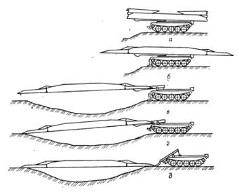
преодолеваемый без подготовки брод 1.4 м., преодолеваемая стенка 0.8 м.
Машина герметизирована, снабжена системой подводного вождения
(движение под водой на глубине до 5 метров), системой противоатомной защиты,
системой автоматического пожаротушения, фильтро — вентиляционной установкой,
благодаря чему, машина может работать на местности зараженной отравляющими и
радиоактивными веществами, причем экипаж в машине может находится без
средств защиты.
От автора. По неизвестным причина в МТУ-20
отказались от крупнокалиберного пулемета и машина фактически оказалась
беззащитной, хотя танкисты, занятые своими задачам, не считали нужным
прикрывать мостоукладчик после того, как он выполнил свою задачу.
По мосту могут следовать как личный состав пешком, так и
все типы колесных и гусеничных машин общей массой до 50 тонн.
Для наводки моста машина выдвигается к преграде, с
помощью гидропривода переводит концевые части моста из транспортного в
рабочее положение. Затем в передней части машины на землю опускается
аутригер (иначе при выдвижении моста на преграду машина наклонится вперед),
мост надвигается на препятствие. Затем машина отходит назад, оставляя мост
на препятствии. Снимать мост с препятствия машина может с исходного или
противоположного берега.
Состоит на вооружении в инженерно-саперной роте
мотострелкового (танкового) полка -1 (3) машины. Поступил на
вооружение на смену мостоукладчика МТУ.
Был создан на базе танка Т-55 в Нижнем Тагиле
конструкторским бюро под руководством Карцева Л.Н, где имел
обозначение «Объект 155А». .
Источники
1. Инструкция по материальной части и эксплуатации
мостоукладчика МТУ-20 . Военное издательство Москва 1973 г.
2. Военно-инженерная подготовка. Учебное пособие. Военное издательство .
Москва. 1982 г.
3. Машины инженерного вооружения. Часть 2. Машины для преодоления
препятствий и водных преград. Воениздат. Москва. 1986 г.
—***—
![]()
©Веремеев Ю.Г.
Главная страница
-инженерная техника
Заметки на полях. Машина была разработана на
замену мостоукладчика МТУ, когда из оперативно —
тактических расчетов новой концепции наступления с широким использованием
бронетехники выяснилось, что в течение суток наступления танковый
(мотострелковый) полк встретит на своем пути не менее двух водных преград
шириной более 15 метров. Получалось, что МТУ с длиной моста 11 метров не в
состоянии обеспечить преодоление полком таких преград.
Однако стальной мост длиной 20 метров слишком
тяжел, большая длина мешала движению по дорогам, по длине он не вписывался
в железнодорожные габариты.
Пришлось разработать мост со складными концами, переводимыми в рабочее или
транспортное положение гидравликой. Для уменьшения веса
мост сделали дюралюминиевым. Однако прочность моста оказалась
неудовлетворительна. После прохода по мосту 15-20 танков мост приходил в
полную негодность. Кроме того он оказался не ремонтнопригодным из-за
того, что для его ремонта требовалась аргонная сварка, которой в войсках не
было. Много проблем создавала и гидросистема. Приказом МО СССР в мирное
время использование моста для реального движения по нему танков было
запрещено.
В результате МТУ-20 заменить МТУ не смог и оказался в
общем-то декоративной машиной. В боевых условиях его практически не
применяли. Снятые с производства МТУ старого образца после поступления
на вооружение МТУ-20, в большей своей части использовались в афганской войне
1979-89 годов. Остатки МТУ были по настоянию ряда стран, оценивших
превосходные боевые качества МТУ, проданы или переданы им, а Советской Армии
остались громоздкие, ломкие, крайне ненадежные, но впечатляющие МТУ-20.
-
Contents
-
Table of Contents
-
Troubleshooting
-
Bookmarks
Quick Links
Operating Instructions
Diesel engine
20 V 4000 G23 with 6 exhaust turbochargers
20 V 4000 G43 with 6 exhaust turbochargers
20 V 4000 G63 with 6 exhaust turbochargers
20 V 4000 G63L with 6 exhaust turbochargers
20 V 4000 G83 with 6 exhaust turbochargers
20 V 4000 G83L with 6 exhaust turbochargers
MS150093/01E
Related Manuals for MTU 20 V 4000 G23
Summary of Contents for MTU 20 V 4000 G23
-
Page 1: Operating Instructions
Operating Instructions Diesel engine 20 V 4000 G23 with 6 exhaust turbochargers 20 V 4000 G43 with 6 exhaust turbochargers 20 V 4000 G63 with 6 exhaust turbochargers 20 V 4000 G63L with 6 exhaust turbochargers 20 V 4000 G83 with 6 exhaust turbochargers…
-
Page 2
This Publication is protected by copyright and may not be used in any way whether in whole or in part without the prior written permission of MTU Friedrichshafen GmbH. This restriction also applies to copyright, distribution, translation, micro‐ filming and storage or processing on electronic systems including data bases and online services. -
Page 3: Table Of Contents
Table of Contents 1 Safety 3.7 Stop engine in manual mode (testing mode) 1.1 General conditions 3.8 Emergency stop 1.2 Personnel and organizational requirements 3.9 After stopping the engine – Engine remains 1.3 Transport ready for operation 1.4 Crankshaft transport locking device 3.10 After stopping the engine –…
-
Page 4
6.14.2 Centrifugal oil filter – Cleaning and filter 7 Appendix A sleeve replacement 7.1 Abbreviations 6.15 Coolant Circuit, General, High- 7.2 MTU contacts/service partners Temperature Circuit 6.15.1 Engine coolant – Level check 6.15.2 Engine coolant – Change 6.15.3 Engine coolant – Draining 8 Appendix B 6.15.4 Engine coolant –… -
Page 5: Safety
Correct use also includes observation of and compliance with the maintenance specifications. Modifications or conversions Unauthorized modifications to the engine represent a safety risk. MTU will accept no liability or warranty claims for any damage caused by unauthorized modifications or conversions. Spare parts Only genuine MTU spare parts must be used to replace components or assemblies.
-
Page 6: Personnel And Organizational Requirements
1.2 Personnel and organizational requirements Personnel requirements All work on the engine shall be carried out by trained and qualified personnel only. The specified legal minimum age must be observed. The operator must specify the responsibilities of the operating, maintenance and repair personnel. Organizational measures This publication must be issued to all personnel involved in operation, maintenance, repair or transporta‐…
-
Page 7: Transport
Place the engine/genset on a firm, flat surface only. Make sure that the consistency and load-bearing capacity of the ground or support surface is adequate. Never set an engine down on the oil pan unless expressively authorized to do so by MTU on a case-to- case basis.
-
Page 8: Crankshaft Transport Locking Device
1.4 Crankshaft transport locking device Special tools, Material, Spare parts Designation / Use Part No. Qty. Torque wrench, 10-60 Nm F30510423 Torque wrench, 60-320 Nm F30047446 Engine oil Transport locking device Note: The locking device protects the crankshaft bearings from shocks and vibration damage during engine transport.
-
Page 9
Fitting the transport locking device on driving end (KS) Note: Attach plates (2) only to the upper part of the openings. Secure the two plates (2) with screws (6) and washers (5) at the bores on both sides of the flywheel housing and tighten to the specified tightening torque. -
Page 10
Installing guard plates and engine mounting brackets (if applicable) on driving end (KS) Note: Always use the screws supplied with the or removed from the guard plates and engine mounting brackets to secure them on the engine. Install engine mounting brackets (2) on both sides with guard plates (1) washers (3), and screws (4). -
Page 11: Explosion Hazard When Removing Inspection Port Cover On Engine
1.5 Explosion hazard when removing inspection port cover on engine DANGER Explosion hazard due to oil vapors. Risk of serious injury – danger to life! • Allow the engine to cool down before opening the crankcase! • Avoid open flames, electrical sparks and ignition sources. Safety instructions Before starting maintenance work, allow the engine to cool down for at least 10 min.
-
Page 12: Safety Regulations For Maintenance And Repair Work
1.6 Safety regulations for maintenance and repair work Safety regulations for maintenance and repair work Have maintenance and repair work carried out by qualified and authorized personnel only. Allow the engine to cool down before starting maintenance work (risk of explosion of oil vapors). Before starting work, relieve pressure in systems and compressed-air lines which are to be opened.
-
Page 13
Do not use the assembly or system as ground terminal. Do not route the welding lead over or near the wiring harnesses of MTU systems. The welding current may otherwise induce an interference voltage in the wiring harnesses which could conceivably damage the electrical system. -
Page 14
For conducting light-beam procedures and measurement work, only the following laser devices must be used: • Laser devices of classes 1, 2 or 3A. • Laser devices of class 3B, which have maximum output in the visible wavelength range (400 to 700 nm), a maximum output of 5 mW, and in which the beam axis and surface are designed to prevent any risk to the eyes. -
Page 15: Auxiliary Materials, Fluids And Lubricants, Fire Prevention And Environmental Protection
Use only fuel of prescribed quality to comply with emission limit values. Dispose of used fluids, lubricants and filters in accordance with local regulations. Within the EU, batteries can be returned free of charge to MTU FN / MTU Onsite Energy where they are subjected to proper recycling procedures.
-
Page 16
Lead • When working with lead or lead-containing compounds, avoid direct contact to the skin and do not inhale lead vapors. • Adopt suitable measures to avoid the formation of lead dust. • Switch on extraction system. • Wash hands after contact with lead or lead-containing substances. Compressed air Observe special safety precautions when working with compressed air: •… -
Page 17: Conventions For Safety Instructions In The Text
1.8 Conventions for safety instructions in the text DANGER In the event of immediate danger. Consequences: Death or serious injury • Remedial action WARNING In the event of potentially dangerous situations. Consequences: Death or serious injury • Remedial action CAUTION In the event of dangerous situations.
-
Page 18: Product Summary
2 Product Summary 2.1 Engine Layout 010 Crankcase and add-on 080 Fuel system (low pres‐ 180 Lube oil system / lube components sure) oil circuit 020 Gear train 100 Exhaust turbocharger 200 Coolant system 030 Running gear 110 Intercooler 210 Power supply 040 Cylinder head 120 Air intake/air supply 230 Mounting/support…
-
Page 19: Overview Of Sensors, Actuators And Injectors
2.2 Overview of sensors, actuators and injectors 1 Temperature sensors 2 Sensor B34 (P-Fuel after 3 M8 (HP fuel pump ac‐ for single exhaust gas filter) tuator) B4.1 to B4.10 (engine side A) The injectors (Y39.1 to Y39.10, engine side A) are underneath the cylinder head covers of the cylinder. Injector replacement and necessary activities (→…
-
Page 20
1 B50 (P crankcase) 5 B07 (T lube oil) 9 B26 (T charge-air cool‐ 2 B05.3 (P lube oil before 6 B01 (N camshaft) ant) filter) 7 B48 (P fuel, rail) 10 B06 (T coolant) 3 B05 (P lube oil after fil‐ 8 B43 (P charge-air cool‐… -
Page 21
1 Temperature sensors 3 B10 (P charge air) for single exhaust gas 4 B09 (T charge air) B4.11 to B4.20 (engine side B) 2 B16 (P coolant) The injectors (Y39.11 to Y39.20, engine side B) are underneath the cylinder head covers of the cylinder. Injector replacement and required procedure (→… -
Page 22
1 B13 (N crankshaft) 22 | Product Summary | MS150093/01E 2012-06… -
Page 23: Engine — Main Dimensions
2.3 Engine – Main dimensions Engine – Main dimensions Length (A) approx. 3560 mm Width (B) approx. 1660 mm Height (C) approx. 2163 mm MS150093/01E 2012-06 | Product Summary | 23…
-
Page 24: Firing Order
2.4 Firing order Firing order Num‐ Firing order ber of cylin‐ ders A1-B4-A4-A2-B3-A3-B2-B1 A1-B5-A5-B3-A3-B6-A6-B2-A2-B4-A4-B1 16 V A1-A7-B4-B6-A4-B8-A2-A8-B3-B5-A3-A5-B2-A6-B1-B7 20 V A1-B5-A8-B7-A5-B2-A7-B10-A2-B3-A10-B6-A3-B4-A6-B9-A4-B1-A9-B8 24 | Product Summary | MS150093/01E 2012-06…
-
Page 25: Final Compression Pressure
2.5 Final compression pressure Final compression pressure Final compression pressure at 120 rpm 24 bar to 28 bar MS150093/01E 2012-06 | Product Summary | 25…
-
Page 26: Engine Side And Cylinder Designations
2.6 Engine side and cylinder designations Engine sides are always designated as viewed from the driving end (KS). The cylinders of the left engine side are designated «A» and those of the right side «B» (as per DIN ISO 1204). The cylinders of each bank are numbered consecutively, starting with No. 1 at the driving end. Other components are numbered in the same way, i.e.
-
Page 27: 4000 Gx3 Engine Data: Continuous
2.7 20V 4000 Gx3 engine data: Continuous operation, variable 3B, optimized fuel consumption Explanation: DL Ref. value: Continuous power BL Ref. value: Fuel stop power A Design value G Guaranteed value R Guideline value L Limit value, up to which the engine can be operated, without change (e.g. of power settings). N Not yet defined value — Not applicable X Applicable…
-
Page 28
Number of cylinders Exhaust gas over‐ pressure Exhaust gas over‐ mbar pressure, max. MODEL-RELATED DATA (basic design) Number of cylin‐ ders Number of cylin‐ ders Cylinder arrange‐ Degrees ment: V-angle Bore Stroke Cylinder displace‐ Liters 4.77 4.77 4.77 4.77 4.77 ment Total displacement Liters… -
Page 29
COOLANT SYSTEM (LT circuit) Number of cylin‐ ders Coolant tempera‐ °C ture before inter‐ cooler (at engine in‐ let inlet from cool‐ ing system) Coolant antifreeze content, max. Pressure loss in off- engine cooling sys‐ tem, max. LUBE OIL SYSTEM Number of cylin‐… -
Page 30
GENERAL OPERATING DATA Number of cylin‐ ders Cold start capabili‐ °C ty: Air temperature (w/o start aid, w/o preheating) — (case Coolant preheating: °C preheating temper‐ ature (min.) Firing speed, from Firing speed, to CAPACITIES Number of cylin‐ ders Engine coolant ca‐ Liters pacity, engine side (without cooling… -
Page 31
ACOUSTICS Number of cylin‐ ders Engine surface dB(A) noise with attenuat‐ ed intake noise (fil‐ ter) — DL (free-field sound power level Lp, 1 m distance, ISO 6798, +2dB(A) tolerance) Engine surface dB(A) noise with attenuat‐ ed intake noise (fil‐ ter) — DL (sound power level LW, ISO 6798, +2dB (A) -
Page 32: Emissions («Ta-Luft»)
2.8 20V 4000 Gx3 engine data: Continuous operation, variable 3B, optimized exhaust emissions («TA-Luft») Explanation: DL Ref. value: Continuous power BL Ref. value: Fuel stop power A Design value G Guaranteed value R Guideline value L Limit value, up to which the engine can be operated, without change (e.g. of power settings). N Not yet defined value — Not applicable X Applicable…
-
Page 33
Number of cylinders Compression ratio 16.4 16.4 16.4 Inlet valves per cylinder Exhaust valves per cylinder COMBUSTION AIR / EXHAUST GAS Number of cylinders Charge air pressure before cylinder, DL bar abs COOLANT SYSTEM (HT circuit) Number of cylinders Coolant temperature (at engine connection: outlet to °C cooling system) Coolant temperature after engine, warning… -
Page 34
GENERAL OPERATING DATA Number of cylinders Cold start capability: Air temperature (w/o start aid, °C w/o preheating) — (case A) Coolant preheating: preheating temperature (min.) °C Firing speed, from Firing speed, to CAPACITIES Number of cylinders Engine coolant capacity, engine side (without cool‐ Liters ing system) Charge-air coolant, engine side… -
Page 35: 4000 Gx3 Engine Data: Standby Operation 3D, Optimized Fuel Consumption, 6Etc
2.9 20 V 4000 Gx3 engine data: Standby operation 3D, optimized fuel consumption, 6ETC Explanation: DL Ref. value: Continuous power BL Ref. value: Fuel stop power A Design value G Guaranteed value r Guideline value L Limit value, up to which the engine can be operated, without change (e.g. of power settings). N Not yet defined value — Not applicable X Applicable…
-
Page 36
MODEL-RELATED DATA (basic design) Number of cylin‐ ders Number of cylin‐ ders Cylinder arrange‐ Degrees ment: V-angle Bore Stroke Cylinder dis‐ Liters 4.77 4.77 4.77 4.77 4.77 4.77 placement Total displace‐ Liters 95.4 95.4 95.4 95.4 95.4 95.4 ment Compression ra‐ 16.4 16.4 16.4… -
Page 37
COOLANT SYSTEM (LT circuit) Number of cylin‐ ders Coolant tempera‐ °C ture before inter‐ cooler (at engine inlet inlet from cooling system) Coolant anti‐ freeze content, max. Pressure loss in off-engine cool‐ ing system, max. LUBE OIL SYSTEM Number of cylin‐ ders Lube oil operat‐… -
Page 38
FUEL SYSTEM Number of cylin‐ ders Fuel pressure at -0.1 -0.1 -0.1 -0.1 -0.1 -0.1 engine inlet con‐ nection, min. (when engine is starting) Fuel pressure at supply connec‐ tion to engine (when engine is starting), max. GENERAL OPERATING DATA Number of cylin‐… -
Page 39
Number of cylin‐ ders Oil pan capacity Liters at dipstick mark “min.” (standard oil system) (op‐ tion: max. operat‐ ing inclinations) Oil pan capacity Liters at dipstick mark “max.” (standard oil system) (op‐ tion: max. operat‐ ing inclinations) WEIGHTS / MAIN DIMENSIONS Number of cylin‐… -
Page 40: Operation
3.1 Putting the engine into operation after extended out-of- service periods (>3 months) Preconditions ☑ Engine is stopped and starting disabled. ☑ MTU Fluids and Lubricants Specifications (A001061/..) are available. Putting into operation after long out-of-service periods (>3 months) Item Action Engine Depreserve (→…
-
Page 41: Putting The Engine Into Operation After Scheduled Out-Of-Service-Period
3.2 Putting the engine into operation after scheduled out-of- service-period Preconditions ☑ Engine is stopped and starting disabled. Putting the engine into operation Item Task Lube oil system Check oil level (→ Page 142); Cooling system Check engine coolant level (→ Page 147); Check charge-air coolant level (→…
-
Page 42: Start Engine In Manual Mode (Testing Mode)
3.3 Start engine in manual mode (testing mode) Preconditions ☑ Generator (if provided) not connected to network. ☑ External start interlock is not activated. DANGER Unguarded rotating and moving engine components. Risk of serious injury – danger to life! • Before barring or starting the engine, make sure that nobody is in the danger zone. WARNING Engine noise above 85 dB (A).
-
Page 43: Safety System — Override
3.4 Safety system – Override CAUTION Safety functions and engine shutdown alarms will be disregarded. Serious damage to plant! • Initiate emergency start only in emergency situations. CAUTION Inadmissible operational condition. Major material damage! • Use override function only in hazardous situations to ensure full capability in case of engine mal‐ functions.
-
Page 44: Operational Checks
3.5 Operational checks DANGER Unguarded rotating and moving engine components. Risk of serious injury – danger to life! • Take special care when working on a running engine. WARNING Engine noise above 85 dB (A). Risk of damage to hearing! •…
-
Page 45: Starting The Engine In Emergency Situations (Override Mode)
3.6 Starting the engine in emergency situations (override mode) CAUTION Safety functions and engine shutdown alarms will be disregarded. Serious damage to plant! • Initiate emergency start only in emergency situations. Preparation Item Task Operating mode switch Set to emergency mode. Starting the engine in emergency situations Item Task…
-
Page 46: Stop Engine In Manual Mode (Testing Mode)
3.7 Stop engine in manual mode (testing mode) Preconditions ☑ Generator (if provided) not connected to network. ☑ Engine is running in manual mode. CAUTION Stopping the engine when it is running at full load causes extreme stress to the engine. Risk of overheating, damage to components! •…
-
Page 47: Emergency Stop
3.8 Emergency stop CAUTION An emergency stop causes extreme stress to the engine. Risk of overheating, damage to components! • Initiate emergency stop only in emergency situations. Emergency stop from LOP Item Task EMERGENCY STOP but‐ Press. • Engine is stopped by switching off power supply to ECU; •…
-
Page 48: After Stopping The Engine — Engine Remains Ready For Operation
3.9 After stopping the engine – Engine remains ready for operation After stopping the engine Item Action Engine/generator/pump Select operating mode, e.g. MANUAL, AUTOMATIC OPERATION. control 48 | Operation | MS150093/01E 2012-06…
-
Page 49: After Stopping The Engine — Putting The Engine Out Of Service
If the engine is to remain out of service for more than 1 week, seal the engine’s air and exhaust sides. If the engine is to remain out of service for more than 1 month, preserve engine (→ MTU Fluids and Lubricants Speci‐ fications A001061/.. ).
-
Page 50: Plant Cleaning
3.11 Plant cleaning Preconditions ☑ Engine is stopped and starting disabled. ☑ Operating voltage is not present. Special tools, Material, Spare parts Designation / Use Part No. Qty. Steam jet cleaner Cleaner (Hakupur 312) 30390 WARNING Compressed air Risk of injury! •…
-
Page 51: Maintenance
4 Maintenance 4.1 Maintenance task reference table [QL1] The maintenance tasks and intervals for this product are defined in the Maintenance Schedule. The Maintenance Schedule is a stand-alone publication. The task numbers in this table provide reference to the maintenance tasks specified in the Maintenance Schedule.
-
Page 52: Troubleshooting
5 Troubleshooting 5.1 Troubleshooting Engine does not turn when starter is actuated Component Probable cause Task Battery Low or defective Charge or replace (see manufacturer’s documentation). Cable connections defective Check if cable connections are proper‐ ly secured (see manufacturer’s docu‐ mentation).
-
Page 53
Defective Contact Service. Charge-air temperature too high Component Probable cause Task Engine coolant Incorrect coolant concentration Check (MTU test kit). Intercooler Contaminated Contact Service. Engine room Air-intake temperature too high Check fans and air supply / ventilation ducts. Charge air pressure too low… -
Page 54
Exhaust gas blue Component Probable cause Task Engine oil Too much engine oil in the engine Drain engine oil (→ Page 140). Oil separator of crankcase breather Replace (→ Page 111). contaminated Exhaust turbocharg‐ Defective Contact Service. er, cylinder head, pis‐ ton rings, cylinder lin‐… -
Page 55: Engine Governor Adec (Ecu 7) For Series 4000 Genset Engines — Fault Messages
5.2 Engine governor ADEC (ECU 7) for Series 4000 genset engines – Fault messages 003 – HI T-Fuel ZKP-Number: 2.0122.931 Limit value 1 Cause Corrective action Fuel temperature too high. u Contact Service. 004 – SS T-Fuel ZKP-Number: 2.0122.932 Limit value 2 Cause Corrective action Fuel temperature too high;…
-
Page 56
010 – SS T-Coolant Intercooler ZKP-Number: 2.0124.932 Limit value 2 Cause Corrective action Coolant temperature in u Reduce power. intercooler too high; engine shutdown. 015 – LO P-Lube Oil ZKP-Number: 2.0100.921 Limit value 1 Cause Corrective action Lube oil pressure too low. u Check oil level, top up as necessary (→… -
Page 57
022 – SS T-Exhaust B ZKP-Number: 2.0127.932 Limit value 2 Cause Corrective action Exhaust gas temperature (B- 1. Check cabling (→ Page 165). side) too high; engine shutdown. 2. Contact Service. 023 – LO Coolant Level ZKP-Number: 2.0152.921 Limit value 1 Cause Corrective action Coolant level too low. -
Page 58
030 – SS Engine Speed ZKP-Number: 2.2510.932 Limit value 2 Cause Corrective action Reduced fuel injection. 1. Acknowledge alarm. 2. Attempt to restart engine. 031 – HI ETC 1 overspeed ZKP-Number: 2.3011.931 Limit value 1 Cause Corrective action Speed of primary turbocharger u Contact Service. -
Page 59
037 – SS ETC 2 Overspeed ZKP-Number: 2.3013.912 Limit value 2 Cause Corrective action Speed of first secondary 1. Reduce power. turbocharger too high. 2. Contact Service. 038 – AL ETC Speed Deviation ZKP-Number: 1.8004.205 Cause Corrective action Synchronization fault between 1. -
Page 60
057 – LO P-Coolant ZKP-Number: 2.0101.921 Limit value 1 Cause Corrective action Coolant pressure too low. u Check coolant circuit. 058 – SS P-Coolant ZKP-Number: 2.0101.922 Limit value 2 Cause Corrective action Coolant pressure too low; engine 1. Automatic engine shutdown. shutdown or reduction of fuel 2. -
Page 61
064 – SS P-Crankcase ZKP-Number: 2.0106.932 Limit value 2 Cause Corrective action Crankcase pressure too high; 1. Replace oil separator element (→ Page 111). engine shutdown. 2. Contact Service. 065 – LO P-Fuel ZKP-Number: 2.0102.921 Limit value 1 Cause Corrective action Fuel supply pressure too low. -
Page 62
081 – AL Rail Leakage ZKP-Number: 1.8004.046 Cause Corrective action Pressure gradient in common rail u Contact Service. too low during engine start or too high during engine stop; HP fuel system leaky, air in system. 082 – HI P-Fuel (Common Rail) ZKP-Number: 2.0104.931 Cause Corrective action… -
Page 63
090 – SS Starter Speed Not Reached ZKP-Number: 2.1090.925 Cause Corrective action Idling speed was not attained. u Contact Service. 091 – SS Release Speed Not Reached ZKP-Number: 2.1090.924 Cause Corrective action Runup speed was not attained. u Contact Service. 092 –… -
Page 64
102 – AL Consumption Meter Faulty ZKP-Number: 1.8004.624 Cause Corrective action consumption meter faulty. u Contact Service. 104 – AL Eng Hours Counter Defect ZKP-Number: 1.8004.623 Cause Corrective action hour meter faulty. u Contact Service. 118 – LO ECU Supply Voltage ZKP-Number: 2.0140.921 Limit value 1 Cause… -
Page 65
122 – HI T-ECU ZKP-Number: 2.0132.921 Limit value 1 Cause Corrective action Electronic unit temperature too 1. Reduce power. high. 2. Improve engine room ventilation. 141 – AL Power too high ZKP-Number: 11.088.007 Cause Corrective action This alarm is activated when the u Reduce power. -
Page 66
180 – AL CAN1 Node Lost ZKP-Number: 2.0500.680 Cause Corrective action Connection to one node on CAN u Contact Service. bus 1 failed. 181 – AL CAN2 Node Lost ZKP-Number: 2.0500.681 Cause Corrective action Connection to one node on CAN u Contact Service. -
Page 67
187 – AL CAN1 Error Passive ZKP-Number: 2.0500.687 Cause Corrective action CAN controller 1 has signaled a 1. Inspect CAN bus for short circuit and rectify short circuit as warning. necessary. 2. Check shielding, improve as necessary. 3. Contact Service. 188 –… -
Page 68
203 – SD T-Charge Air ZKP-Number: 1.8004.571 Cause Corrective action Charge-air temperature sensor u Check sensor and cabling (B9), replace as necessary. faulty; short circuit or wire break. Error cleared after restarting the engine. 204 – SD Level Lube Oil ZKP-Number: 1.8004.602 Cause Corrective action… -
Page 69
211 – SD P-Lube Oil ZKP-Number: 1.8004.563 Cause Corrective action Lube-oil pressure sensor faulty; u Check sensor and cabling (B5), replace as necessary. short circuit or wire break. Error cleared after restarting the engine. 212 – SD P-Coolant ZKP-Number: 1.8004.564 Cause Corrective action Coolant pressure sensor faulty;… -
Page 70
219 – SD T-Intake Air ZKP-Number: 1.8004.573 Cause Corrective action Intake air temperature sensor u Check sensor and cabling (B3), replace as necessary. faulty; short circuit or wire break. Error cleared after restarting the engine. 220 – SD Coolant Level ZKP-Number: 1.8004.584 Cause Corrective action… -
Page 71
228 – SD P-Fuel before Filter ZKP-Number: 18.004.595 Cause Corrective action Fuel pressure sensor faulty; u Check sensor and cabling (B5.3), replace as necessary. short circuit or wire break. 229 – AL Stop Camshaft Sensor Defect ZKP-Number: 1.8004.562 Cause Corrective action engine stop due to camshaft u Check connector and cabling to sensor B1, replace as sensor fault (and a prior… -
Page 72
239 – SD P-Diff Fuel ZKP-Number: 18.004.598 Cause Corrective action Fuel differential pressure sensor u Note further fault messages. faulty. This alarm occurs only in combination with the alarm SD P-Fuel before Filter or SD P-Fuel after Filter. 240 – SD P-Fuel ZKP-Number: 1.8004.565 Cause Corrective action… -
Page 73
266 – SD Speed Demand ZKP-Number: 2.8006.586 Cause Corrective action Analog speed demand signal 1. Check cabling. faulty; short circuit or wire break. 2. Check speed demand signal. 268 – SD Spinning Value ZKP-Number: 28.006.591 Cause Corrective action Analog wheel slip signal faulty; u Check sensor and cabling, replace as necessary. -
Page 74
303 – AL Timing Cylinder A3 ZKP-Number: 1.8004.502 Cause Corrective action Time-of-flight measuring fault of u Replace injector concerned if the fault message appears injector: time-of flight measured frequently (→ Page 119). value extremely low or extremely high. 304 – AL Timing Cylinder A4 ZKP-Number: 1.8004.503 Cause Corrective action… -
Page 75
308 – AL Timing Cylinder A8 ZKP-Number: 1.8004.507 Cause Corrective action Time-of-flight measuring fault of u Replace injector concerned if the fault message appears injector: time-of flight measured frequently (→ Page 119). value extremely low or extremely high. 309 – AL Timing Cylinder A9 ZKP-Number: 1.8004.508 Cause Corrective action… -
Page 76
313 – AL Timing Cylinder B3 ZKP-Number: 1.8004.512 Cause Corrective action Time-of-flight measuring fault of u Replace injector concerned if the fault message appears injector: time-of flight measured frequently (→ Page 119). value extremely low or extremely high. 314 – AL Timing Cylinder B4 ZKP-Number: 1.8004.513 Cause Corrective action… -
Page 77
318 – AL Timing Cylinder B8 ZKP-Number: 1.8004.517 Cause Corrective action Time-of-flight measuring fault of u Replace injector concerned if the fault message appears injector: time-of flight measured frequently (→ Page 119). value extremely low or extremely high. 319 – AL Timing Cylinder B9 ZKP-Number: 1.8004.518 Cause Corrective action… -
Page 78
324 – AL Wiring Cylinder A4 ZKP-Number: 1.8004.523 Cause Corrective action Cabling fault in injector cabling to 1. Check solenoid valve. cylinder. Result: misfiring. 2. Contact Service. 325 – AL Wiring Cylinder A5 ZKP-Number: 1.8004.524 Cause Corrective action Cabling fault in injector cabling to 1. -
Page 79
331 – AL Wiring Cylinder B1 ZKP-Number: 1.8004.530 Cause Corrective action Cabling fault in injector cabling to 1. Check solenoid valve. cylinder. Result: misfiring. 2. Contact Service. 332 – AL Wiring Cylinder B2 ZKP-Number: 1.8004.531 Cause Corrective action Cabling fault in injector cabling to 1. -
Page 80
338 – AL Wiring Cylinder B8 ZKP-Number: 1.8004.537 Cause Corrective action Cabling fault in injector cabling to 1. Check solenoid valve. cylinder. Result: misfiring. 2. Contact Service. 339 – AL Wiring Cylinder B9 ZKP-Number: 1.8004.538 Cause Corrective action Cabling fault in injector cabling to 1. -
Page 81
345 – AL Open Load Cylinder A5 ZKP-Number: 1.8004.544 Cause Corrective action Disruption fault in injector cabling 1. Check solenoid valve. to cylinder. Result: misfiring. 2. Contact Service. 346 – AL Open Load Cylinder A6 ZKP-Number: 1.8004.545 Cause Corrective action Disruption fault in injector cabling 1. -
Page 82
352 – AL Open Load Cylinder B2 ZKP-Number: 1.8004.551 Cause Corrective action Disruption fault in injector cabling 1. Check solenoid valve. to cylinder. Result: misfiring. 2. Contact Service. 353 – AL Open Load Cylinder B3 ZKP-Number: 1.8004.552 Cause Corrective action Disruption fault in injector cabling 1. -
Page 83
359 – AL Open Load Cylinder B9 ZKP-Number: 1.8004.558 Cause Corrective action Disruption fault in injector cabling 1. Check solenoid valve. to cylinder. Result: misfiring. 2. Contact Service. 360 – AL Open Load Cylinder B10 ZKP-Number: 1.8004.559 Cause Corrective action Disruption fault in injector cabling 1. -
Page 84
365 – AL Stop MV-Wiring Ground ZKP-Number: 1.8004.561 Cause Corrective action Injector cabling fault. If bit 1. Check cabling. “1.1020.021” (Power Stage 2. Attempt to restart engine. Failure: stop engine) is set, engine will be shut down as additional measure. 1. Short circuit of positive connection of one or more injectors to ground 2. -
Page 85
381 – AL Wiring TOP 1 ZKP-Number: 2.8006.638 Cause Corrective action Short circuit or wire break on u Check cabling to plant. transistor output, plant-side 1 (TOP 1). 382 – AL Wiring TOP 2 ZKP-Number: 2.8006.639 Cause Corrective action Short circuit or wire break on u Check cabling to plant. -
Page 86
393 – SS T-Coolant Red ZKP-Number: 2.0129.932 Limit value 2 Cause Corrective action Redundant coolant temperature 1. Check cabling and sensor. reading too high; engine 2. Contact Service. shutdown. 394 – LO P-Lube Oil Red ZKP-Number: 2.0112.921 Limit value 1 Cause Corrective action Redundant lube oil pressure… -
Page 87
401 – AL Open Load Digital Input 2 ZKP-Number: 2.8006.626 Cause Corrective action Open circuit at digital input 2; 1. Check cabling. cabling faulty or no resistance 2. Check input of target device. across the switch. 3. Contact Service. 402 – AL Open Load Digital Input 3 ZKP-Number: 2.8006.627 Cause Corrective action… -
Page 88
407 – AL Open Load Digital Input 8 ZKP-Number: 2.8006.632 Cause Corrective action Open circuit at digital input 8; 1. Check cabling. cabling faulty or no resistance 2. Check input of target device. across the switch. 3. Contact Service. 408 – AL Open Load Emerg. Stop Input ESI ZKP-Number: 2.8006.633 Cause Corrective action… -
Page 89
413 – HIHI U-PDU ZKP-Number: 2.0141.932 Limit value 2 Cause Corrective action Injector voltage too high. 1. Check cabling. 2. Check power supply. 3. Contact Service. 414 – HI Water Level Fuel Prefilter ZKP-Number: 2.0156.931 Limit value 1 Cause Corrective action Water level in fuel prefilter too u Drain water (→… -
Page 90
420 – AL L1 Aux 1 ZKP-Number: 2.0160.921 Limit value 1 Cause Corrective action Input signal of Aux 1 has u Determine and rectify reason for limit value violation. exceeded/not attained limit value 1, depending on configuration. 421 – AL L2 Aux 1 ZKP-Number: 2.0160.922 Limit value 2 Cause… -
Page 91
434 – HI T-Coolant before Engine ZKP-Number: 20.173.931 Limit value 1 Cause Corrective action Coolant temperature too high. u Check coolant circuit. 435 – SS T-Coolant before Engine ZKP-Number: 20.173.932 Limit value 2 Cause Corrective action Coolant temperature too high. u Check coolant circuit. -
Page 92
448 – HI P-Charge Air ZKP-Number: 2.0103.931 Limit value 1 Cause Corrective action Charge-air pressure too high. u Contact Service. 449 – SS P-Charge Air ZKP-Number: 2.0103.932 Limit value 2 Cause Corrective action Charge-air pressure too high. u Contact Service. 450 –… -
Page 93
460 – HI T-Exhaust EMU ZKP-Number: 2.8006.652 Limit value 1 Cause Corrective action EMU exhaust gas temperature 1. Check cabling. value too high. 2. Contact Service. 461 – LO T-Exhaust EMU ZKP-Number: 2.8006.653 Limit value 1 Cause Corrective action EMU exhaust gas temperature 1. -
Page 94
469 – SD AUX 1 ZKP-Number: 1.8004.590 Cause Corrective action Analog input signal for Aux 1 u Check signal transmitter and cabling, replace as necessary. faulty; short circuit or wire break. Error cleared after restarting the engine. 470 – SD T-ECU ZKP-Number: 1.8004.587 Cause Corrective action… -
Page 95
475 – AL CR Trigger Engine Stop ZKP-Number: 1.8010.009 Cause Corrective action Tripped by crash recorder u Determine and rectify cause of triggering / engine shutdown. triggering due to engine shutdown. 476 – AL Crash Rec. Init. Error ZKP-Number: 1.8010.007 Cause Corrective action Crash recorder initialization… -
Page 96
483 – SD T-Exhaust D ZKP-Number: 18.004.597 Cause Corrective action Exhaust temperature sensor on u Check sensor and cabling (B4.24), replace as necessary. A-side faulty; short circuit or wire break. 484 – HI T-Exhaust C ZKP-Number: 20.133.931 Limit value 1 Cause Corrective action Exhaust gas temperature (C-… -
Page 97
489 – SS ETC3 Overspeed ZKP-Number: 23.014.932 Limit value 2 Cause Corrective action Speed of second secondary u Reduce power. turbocharger too high. 490 – HI ETC4 Overspeed ZKP-Number: 23.015.931 Limit value 1 Cause Corrective action Speed of third secondary u Reduce power. -
Page 98
501 – AL Wiring POM Starter 2 ZKP-Number: 14.500.901 Cause Corrective action A wiring fault was detected in the u Check connection between POM and starter. connection of starter 2 of the CPM. The root cause might be a missing consumer, a wire break or a short circuit. -
Page 99
508 – AL Wrong POM-ID ZKP-Number: 14.500.908 Cause Corrective action POM transmits a different ID No. u Check POM wiring harness. than expected. 510 – AL Override applied ZKP-Number: 27.002.010 Cause Corrective action Override was activated. u Deactivate Override pushbutton. 515 –… -
Page 100
524 – SS Engine Overspeed Mid Val ZKP-Number: 20.480.089 Limit value 2 Cause Corrective action Average engine overspeed value 1. Acknowledge alarm. from three sources is too high. 2. Attempt to restart engine. 525 – SD P-Lube Oil (R2) ZKP-Number: 18.004.638 Cause Corrective action Redundant lube oil pressure… -
Page 101
530 – SS P-Lube Oil Red2 ZKP-Number: 20.480.295 Limit value 2 Cause Corrective action Second redundant lube-oil u Check oil level, top up as necessary . pressure too high. 543 – AL Multiple FDH Slaves ZKP-Number: 20.555.005 Cause Corrective action There is more than one unit u Contact Service. -
Page 102
Limit value 2 Cause Corrective action Camshaft overspeed. 1. Acknowledge alarm. 2. Attempt to restart engine. 555 – AL Call MTU Field Service ZKP-Number: 20.555.001 Cause Corrective action This alarm is activated if the u Request activation code via internet. -
Page 103
579 – AL MD CAN Request Idle Speed ZKP-Number: 21.063.511 Cause Corrective action MD forced idle demand => node failure (node 3,4 or 5) 580 – AL MD CAN Speed Limitation ZKP-Number: 21.063.513 Cause Corrective action MD speed limitation demand => node failure (node 3,4 or 5) 581 –… -
Page 104: Task Description
6 Task Description 6.1 Engine 6.1.1 Engine – Barring manually Preconditions ☑ Engine is stopped and starting disabled. Special tools, Material, Spare parts Designation / Use Part No. Qty. Barring device F6555766 Ratchet with extension F30006212 DANGER Unguarded rotating and moving engine components. Risk of serious injury –…
-
Page 105: Engine — Barring With Starting System
6.1.2 Engine – Barring with starting system DANGER Unguarded rotating and moving engine components. Risk of serious injury – danger to life! • before barring or starting the engine, ensure that nobody is in the danger zone. • After working on the engine, check that all protective devices have been reinstalled and all tools removed from the engine.
-
Page 106: Engine — Test Run
6.1.3 Engine – Test run DANGER Unguarded rotating and moving engine components. Risk of serious injury – danger to life! • Before barring or starting the engine, make sure that nobody is in the danger zone. WARNING Engine noise above 85 dB (A). Risk of damage to hearing! •…
-
Page 107: Cylinder Liner
6.2 Cylinder Liner 6.2.1 Cylinder liner – Endoscopic examination Preconditions ☑ Engine is stopped and starting disabled Special tools, Material, Spare parts Designation / Use Part No. Qty. Rigid endoscope Y20097353 Preparatory steps Remove cylinder head cover (→ Page 117). Remove injector (→…
-
Page 108
Final steps Install injector (→ Page 120). Install cylinder head cover (→ Page 117). 108 | Task Description | MS150093/01E 2012-06… -
Page 109: Cylinder Liner — Instructions And Comments On Endoscopic And Visual Examination
6.2.2 Cylinder liner – Instructions and comments on endoscopic and visual examination Terms used for endoscopic examination Use the terms listed below to describe the condition of the cylinder-liner surface in the endoscopic exami‐ nation report. Findings Measure Minor dirt scores Minor dirt scores can occur during the assembly of a new engine (honing prod‐…
-
Page 110
Findings Measure Burn mark This is caused by a malfunction in the liner / ring tribosystem. Usually they run over the whole ring-travel area (TDC/BDC), starting at the first TDC-ring and becoming more visible from the second TDC-ring 2 onwards and less pro‐ nounced from TDC-ring 1. -
Page 111: Crankcase Breather
6.3 Crankcase Breather 6.3.1 Crankcase breather – Oil mist fine separator replacement Preconditions ☑ Engine is stopped and starting disabled. Special tools, Material, Spare parts Designation / Use Part No. Qty. Engine oil Oil mist fine separator (→ Spare Parts Catalog) O-ring (→…
-
Page 112: Valve Drive
6.4 Valve Drive 6.4.1 Valve gear – Lubrication Preconditions ☑ Engine is stopped and starting disabled. Special tools, Material, Spare parts Designation / Use Part No. Qty. Engine oil Valve gear – Lubrication Remove cylinder head covers (→ Page 117). Fill oil chambers of valve bridges with oil.
-
Page 113: Valve Clearance — Check And Adjustment
6.4.2 Valve clearance – Check and adjustment Preconditions ☑ Engine is stopped and starting disabled. ☑ Engine coolant temperature is max. 40 °C. ☑ Valves are closed. Special tools, Material, Spare parts Designation / Use Part No. Qty. Feeler gauge Y20098771 Torque wrench, 60-320 Nm F30452768…
-
Page 114
Rotate crankshaft with barring device in di‐ rection of engine rotation until TDC-A1 marking and pointer are aligned. Diagram for 8V engines (two crankshaft positions) 1 Cylinder A1 is in firing TDC 2 Cylinder A1 is in overlap TDC I Inlet valve X Exhaust valve Diagram for 12V engines (two crankshaft positions) -
Page 115
Diagram for 16V engines (two crankshaft positions) 1 Cylinder A1 is in firing TDC 2 Cylinder A1 is in overlap TDC I Inlet valve X Exhaust valve Diagram for 20V engines (two crankshaft positions) 1 Cylinder A1 is in firing TDC 2 Cylinder A1 is in overlap TDC I Inlet valve X Exhaust valve… -
Page 116
Adjusting valve clearance Release locknut (1). Insert feeler gauge between valve bridge and rocker arm. Use Allen key to set adjusting screw (2) so that the specified valve clearance is estab‐ lished. Feeler gauge must just pass through the gap. Tighten locknut (1) with torque wrench to the specified tightening torque, holding the adjusting screw (2) to prevent it from turning. -
Page 117: Cylinder Head Cover — Removal And Installation
6.4.3 Cylinder head cover – Removal and installation Preconditions ☑ Engine is stopped and starting disabled. Special tools, Material, Spare parts Designation / Use Part No. Qty. Grease (Kluthe Hakuform 30-10/Emulgier) X00058061 O-ring (→ Spare Parts Catalog) Removing cylinder head cover Clean very dirty cylinder head covers (3) prior to removal.
-
Page 118: Injection Pump / Hp Pump
6.5 Injection Pump / HP Pump 6.5.1 HP pump – Filling with engine oil Preconditions ☑ Engine is stopped and starting disabled. Special tools, Material, Spare parts Designation / Use Part No. Qty. Engine oil WARNING Fuels are combustible. Risk of fire and explosion! •…
-
Page 119: Injection Valve / Injector
6.6 Injection Valve / Injector 6.6.1 Injector – Replacement Special tools, Material, Spare parts Designation / Use Part No. Qty. Injector (→ Spare Parts Catalog) Replacing injector Remove injector and install new injector (→ Page 120). MS150093/01E 2012-06 | Task Description | 119…
-
Page 120: Injector — Removal And Installation
6.6.2 Injector – Removal and installation Preconditions ☑ Engine is stopped and starting disabled. Special tools, Material, Spare parts Designation / Use Part No. Qty. Installation/removal tool F6789889 Milling cutter F30452739 Torque wrench, 0.5-5 Nm 0015384230 Torque wrench, 10-60 Nm F30452769 Torque wrench, 60-320 Nm F30452768…
-
Page 121
Remove HP fuel line (4). Remove return line (5). Note: The injector accumulator will be emptied when removing the adapter. Remove adapter (3). Remove screw (2) and take off hold-down clamp (1). Install installation/removal tool on cylinder head. Remove injector with installation/removal tool. -
Page 122: Installing Injector
Installing injector Remove plug before installing the injec‐ tor. (Do not remove the plug from the HP line before installing the adapter.) Coat injector with assembly paste at the seat of the nozzle clamping nut. Fit new sealing ring (4) (included in the scope of supply of the injector) with grease on injector, observe installation position of sealing ring (4).
-
Page 123
Coat screw head mating face (2) and thread with engine oil. Fit hold-down clamp (1) in the correct position and use torque wrench to tighten screw (2) to the specified initial tightening torque. Name Size Type Lubricant Value/Standard Screw Preload torque (Engine oil) 5 Nm to 10 Nm Note:… -
Page 124
Mount double-walled HP line (5) and use torque wrench to tighten to the specified torque. Tightening sequence: 1 Adapter (4) 2 Rail (6) Name Size Type Lubricant Value/Standard Union nut / thrust Tightening torque 40 Nm + 5 Nm screw Fit cable connector onto injector. -
Page 125: Fuel System
6.7 Fuel System 6.7.1 Fuel system – Venting Preconditions ☑ Engine is stopped and starting disabled. Special tools, Material, Spare parts Designation / Use Part No. Qty. Diesel fuel WARNING Fuels are combustible. Risk of fire and explosion! • Avoid open flames, electrical sparks and ignition sources. •…
-
Page 126: Fuel Filter
6.8 Fuel Filter 6.8.1 Fuel filter – Replacement Preconditions ☑ Engine is stopped and starting disabled. Special tools, Material, Spare parts Designation / Use Part No. Qty. Filter wrench F30379104 Engine oil Easy-change filter (→ Spare Parts Catalog) WARNING Fuels are combustible. Risk of fire and explosion! •…
-
Page 127: Fuel Prefilter Cleaning
6.8.2 Fuel prefilter cleaning Preconditions ☑ Engine is stopped and starting disabled. Special tools, Material, Spare parts Designation / Use Part No. Qty. Diesel fuel Sealing ring (→ Spare Parts Catalog) WARNING Fuels are combustible. Risk of fire and explosion! •…
-
Page 128: Fuel Prefilter – Differential Pressure Gauge Check And Adjustment
6.8.3 Fuel prefilter – Differential pressure gauge check and adjustment DANGER Unguarded rotating and moving engine components. Risk of serious injury – danger to life! • Take special care when working on a running engine. WARNING Engine noise above 85 dB (A). Risk of damage to hearing! •…
-
Page 129: Fuel Prefilter – Draining
6.8.4 Fuel prefilter – Draining Preconditions ☑ Engine is stopped and starting disabled. Special tools, Material, Spare parts Designation / Use Part No. Qty. Diesel fuel Gasket (→ Spare Parts Catalog) WARNING Fuels are combustible. Risk of fire and explosion! •…
-
Page 130: Fuel Prefilter ‒ Flushing
6.8.5 Fuel prefilter ‒ Flushing Special tools, Material, Spare parts Designation / Use Part No. Qty. Fuel Gasket (→ Spare Parts Catalog) DANGER Unguarded rotating and moving engine components. Risk of serious injury – danger to life! • Take special care when working on a running engine. WARNING Fuels are combustible.
-
Page 131
Open threaded vent plug (5) of filter to be flushed. Unlock drain valve (6) by pressing valve toggle, open it and drain fuel. Result: Fuel flows from filtered side back to the un‐ filtered side, flushing the filter deposits downwards out of the filter. Close threaded vent plug (5) and drain valve (6). -
Page 132: Fuel Prefilter – Filter Element Replacement
6.8.6 Fuel prefilter – Filter element replacement Preconditions ☑ Engine is stopped and starting disabled. Special tools, Material, Spare parts Designation / Use Part No. Qty. Diesel fuel Filter element (→ Spare Parts Catalog) Gasket (→ Spare Parts Catalog) WARNING Fuels are combustible.
-
Page 133
Open threaded vent plug (5) of contaminat‐ ed filter. Unlock drain valve (6) by pressing toggle and open it. Drain water and dirt from filter. Close drain valve (6). Remove screws securing the cover and take off cover (2). Remove spring housing (4) and filter ele‐ ment (3). -
Page 134: Charge-Air Cooling
6.9 Charge-Air Cooling 6.9.1 Intercooler – Checking condensate drain for coolant discharge and obstructions DANGER Unguarded rotating and moving engine components. Risk of serious injury – danger to life! • Take special care when working on a running engine. WARNING Engine noise above 85 dB (A).
-
Page 135: Air Filter – Replacement
6.10 Air Filter 6.10.1 Air filter – Replacement Special tools, Material, Spare parts Designation / Use Part No. Qty. Air filter (→ Spare Parts Catalog) Air filter – Replacement Remove air filter and install new one (→ Page 137). Reset signal ring of service indicator (→ Page 138). MS150093/01E 2012-06 | Task Description | 135…
-
Page 136: Air Filter – Check
6.10.2 Air filter – Check Special tools, Material, Spare parts Designation / Use Part No. Qty. Air filter (→ Spare Parts Catalog) Air filter – Check Check entire circumference of air filter for damage. Fit new air filter if damaged (→ Page 137). 136 | Task Description | MS150093/01E 2012-06…
-
Page 137: Air Filter – Removal And Installation
6.10.3 Air filter – Removal and installation Preconditions ☑ Engine is stopped and starting disabled. Removing and installing air filter Release clamp (2). Remove air filter (3) and clamp (2) from connecting flange of intake housing (1). Verify that there are no objects in the con‐ necting flange of the intake housing (1) and clean it.
-
Page 138: Contamination Indicator – Signal Ring Position Check (Optional)
6.11 Air Intake 6.11.1 Contamination indicator – Signal ring position check (optional) Preconditions ☑ Engine is stopped and starting disabled. Checking signal ring position If the signal ring is completely visible in the observation window (2), replace air filter (→ Page 135). After installation of new filter, press reset button (1).
-
Page 139: Air Starter – Manual Operation
6.12 Starting Equipment 6.12.1 Air starter – Manual operation DANGER Unguarded rotating and moving engine components. Risk of serious injury – danger to life! • Before barring or starting the engine, make sure that nobody is in the danger zone. WARNING Engine noise above 85 dB (A).
-
Page 140: Engine Oil – Change
6.13 Lube Oil System, Lube Oil Circuit 6.13.1 Engine oil – Change Preconditions ☑ Engine is stopped and starting disabled. ☑ Engine is at operating temperature. ☑ MTU fluids and lubricants specifications (A001061/..) are available. Special tools, Material, Spare parts Designation / Use Part No. Qty.
-
Page 141
Draining residual oil from equipment carrier (only with unscheduled engine oil change) Provide a suitable container in which to col‐ lect the engine oil. Remove drain plug (1) and drain engine oil from engine oil heat exchanger and from engine oil filter. Remove drain plugs (2) and (3) and drain engine oil. -
Page 142: Engine Oil Level – Check
6.13.2 Engine oil level – Check Preconditions ☑ Engine shut down and starting disabled. Checking oil level prior to engine start Withdraw oil dipstick from guide tube and wipe it. Insert oil dipstick into guide tube up to stop, withdraw after approx. 10 seconds and check oil level.
-
Page 143: Engine Oil – Sample Extraction And Analysis
6.13.3 Engine oil – Sample extraction and analysis Preconditions ☑ MTU Fluids and Lubricants Specifications (A001061/..) are available. Special tools, Material, Spare parts Designation / Use Part No. Qty. MTU test kit 5605892099/00 DANGER Unguarded rotating and moving engine components.
-
Page 144: Engine Oil Filter – Replacement
6.14 Oil Filtration / Cooling 6.14.1 Engine oil filter – Replacement Preconditions ☑ Engine is stopped and starting disabled. Special tools, Material, Spare parts Designation / Use Part No. Qty. Filter wrench F30379104 Engine oil Oil filter (→ Spare Parts Catalog) WARNING Hot oil.
-
Page 145: Centrifugal Oil Filter – Cleaning And Filter Sleeve Replacement
6.14.2 Centrifugal oil filter – Cleaning and filter sleeve replacement Preconditions ☑ Engine is stopped and starting disabled. Special tools, Material, Spare parts Designation / Use Part No. Qty. Torque wrench, 6-50 Nm F30027336 Cold cleaner (Hakutex 60) X00056750 Filter sleeve (→…
-
Page 146
Centrifugal oil filter cleaning and filter sleeve replacement Remove clamp (14). Release cover screw (2) and take off cov‐ er (1). Carefully lift rotor (11), allow oil to drain and remove from housing. Holding the rotor (11) firmly, release rotor cover nut (3). -
Page 147: Coolant Circuit, General, High Temperature Circuit
6.15 Coolant Circuit, General, High-Temperature Circuit 6.15.1 Engine coolant – Level check Preconditions ☑ Engine is stopped and starting disabled. ☑ MTU Fluids and Lubricants Specifications (A001061/..) are available. WARNING Coolant is hot and under pressure. Risk of injury and scalding! •…
-
Page 148: Engine Coolant – Change
6.15.2 Engine coolant – Change Special tools, Material, Spare parts Designation / Use Part No. Qty. Coolant Engine coolant – Change Drain engine coolant (→ Page 149). Fill with engine coolant (→ Page 150). 148 | Task Description | MS150093/01E 2012-06…
-
Page 149: Engine Coolant – Draining
6.15.3 Engine coolant – Draining Preconditions ☑ Engine is stopped and starting disabled. WARNING Coolant is hot and under pressure. Risk of injury and scalding! • Let the engine cool down. • Wear protective clothing, gloves, and goggles / safety mask. Preparatory steps Provide an appropriate container to drain the coolant into.
-
Page 150: Engine Coolant – Filling
6.15.4 Engine coolant – Filling Preconditions ☑ Engine is stopped and starting disabled. ☑ MTU Fluids and Lubricants Specifications (A001061/..) are available. Special tools, Material, Spare parts Designation / Use Part No. Qty. Engine coolant WARNING Coolant is hot and under pressure.
-
Page 151
Filling coolant with pump Connect appropriate pump with hose to the drain valve of the engine coolant pump (ar‐ row). Open venting point at distributor (arrow). Open drain valve and pump coolant into en‐ gine at 0.5 bar minimum. Close venting point when coolant emerges. Fill expansion tank until overflow edge is reached. -
Page 152
Alternatively: Filling coolant through filler neck Open venting point at distributor (arrow). Fill in coolant in expansion tank via filler neck until coolant level at top edge of filler neck remains constant. Close venting point when coolant emerges. Check proper condition of breather valve on coolant expansion tank, clean sealing faces if required. -
Page 153: Engine Coolant Pump – Relief Bore Check
6.15.5 Engine coolant pump – Relief bore check DANGER Unguarded rotating and moving engine components. Risk of serious injury – danger to life! • Take special care when working on a running engine. WARNING Engine noise above 85 dB (A). Risk of damage to hearing! •…
-
Page 154: Engine Coolant – Sample Extraction And Analysis
6.15.6 Engine coolant – Sample extraction and analysis Preconditions ☑ MTU Fluids and Lubricants Specifications (A001061/..) are available. Special tools, Material, Spare parts Designation / Use Part No. Qty. MTU test kit 5605892099/00 DANGER Unguarded rotating and moving engine components.
-
Page 155: Charge-Air Coolant – Level Check
6.16 Low-Temperature Circuit 6.16.1 Charge-air coolant – Level check Preconditions ☑ Engine is stopped and starting disabled. ☑ MTU Fluids and Lubricants Specifications (A001061/..) are available. WARNING Coolant is hot and under pressure. Risk of injury and scalding! • Let the engine cool down.
-
Page 156: Charge-Air Coolant – Change
6.16.2 Charge-air coolant – Change Special tools, Material, Spare parts Designation / Use Part No. Qty. Coolant Charge-air coolant – Change Drain charge-air coolant (→ Page 157). Fill with charge-air coolant (→ Page 158). 156 | Task Description | MS150093/01E 2012-06…
-
Page 157: Charge-Air Coolant – Draining
6.16.3 Charge-air coolant – Draining Preconditions ☑ Engine is stopped and starting disabled. Special tools, Material, Spare parts Designation / Use Part No. Qty. Sealing ring (→ Spare Parts Catalog) WARNING Coolant is hot and under pressure. Risk of injury and scalding! •…
-
Page 158: Charge-Air Coolant – Filling
6.16.4 Charge-air coolant – Filling Preconditions ☑ Engine is stopped and starting disabled. ☑ MTU Fluids and Lubricants Specifications (A001061/..) are available. Special tools, Material, Spare parts Designation / Use Part No. Qty. Charge-air coolant WARNING Coolant is hot and under pressure.
-
Page 159
Filling coolant with pump Connect a suitable pump with a hose to the drain valve (arrowed). Undo the vent line union at the distributor piece (arrowed). Open drain valve and pump coolant into en‐ gine at 0.5 bar minimum. Tighten the union (arrowed) if coolant leaks out at the loose union. -
Page 160
Alternatively: Filling coolant through filler neck Undo the vent line union at the distributor piece (arrowed). Fill in coolant in expansion tank via filler neck until coolant level at top edge of filler neck remains constant. Tighten the union (arrowed) if coolant leaks out at the loose union. -
Page 161: Charge-Air Coolant Pump – Relief Bore Check
6.16.5 Charge-air coolant pump – Relief bore check DANGER Unguarded rotating and moving engine components. Risk of serious injury – danger to life! • Take special care when working on a running engine. WARNING Engine noise above 85 dB (A). Risk of damage to hearing! •…
-
Page 162: Belt Drive
6.17 Belt Drive 6.17.1 Drive belt – Condition check Preconditions ☑ Engine is stopped and starting disabled. ☑ Guard is removed. Drive belt – Condition check Item Findings Action Drive belt A Singular cracks None Drive belt Belt is oily, shows signs of over‐ Replace (→…
-
Page 163: Battery-Charging Generator
6.18 Battery-Charging Generator 6.18.1 Battery-charging generator drive – Drive belt tension adjustment Preconditions ☑ Engine is stopped and starting disabled. WARNING Spring/circlip/tensioning roller preload. Risk of injury! • Only use specified tool and equipment. Adjusting belt tension Remove protective cover. Slacken screws (1) and (2) by half a turn.
-
Page 164: Replacement
6.18.2 Battery-charging generator drive – Drive belt replacement Preconditions ☑ Engine is stopped and starting disabled. Special tools, Material, Spare parts Designation / Use Part No. Qty. Drive belt (→ Spare Parts Catalog) WARNING Spring/circlip/tensioning roller preload. Risk of injury! •…
-
Page 165: Wiring (General) For Engine/Gearbox/Unit
6.19 Wiring (General) for Engine/Gearbox/Unit 6.19.1 Engine wiring – Check Preconditions ☑ Engine is stopped and starting disabled. Special tools, Material, Spare parts Designation / Use Part No. Qty. Isopropyl alcohol X00058037 Engine wiring – Check Check securing screws of cable clamps on engine and tighten loose threaded connections. Ensure that cables are fixed in their clamps and cannot swing freely.
-
Page 166: Engine Mounting / Support
6.20 Engine Mounting / Support 6.20.1 Engine mounting – Check Engine mounting – Check Item Findings Action Visually inspect mounts. • Damage Replace (→ Instructions for Gen‐ • Brittleness eral Overhaul) • Deformation • Crack formation • Swelling visible 166 | Task Description | MS150093/01E 2012-06…
-
Page 167: Cdc Parameters – Reset With Diasys
6.21 Accessories for (Electronic) Engine Governor / Control System 6.21.1 CDC parameters – Reset with DiaSys® Preconditions ☑ Engine is stopped and starting disabled. Resetting CDC parameters (DiaSys® is available) Note: The CDC parameters must be reset, otherwise the emission certification of the engine is no longer appli‐ cable.
-
Page 168: Engine Governor And Connectors – Cleaning
6.21.2 Engine governor and connectors – Cleaning Preconditions ☑ Engine is stopped and starting disabled. Special tools, Material, Spare parts Designation / Use Part No. Qty. Isopropyl alcohol X00058037 Note: Always use test connectors to enter the connectors. Never use test leads for this purpose.Otherwise the contacts could be bent.
-
Page 169: Connections
6.21.3 Engine governor – Checking plug-in connections Preconditions ☑ Engine is stopped and starting disabled. Note: Always use test connectors to enter the connectors. Never use test leads for this purpose.Otherwise the contacts could be bent. Checking plug-in connections on engine governor Check all plug-in connections for secure seating.
-
Page 170: Ecu 7 Engine Governor – Removal And Installation
6.21.4 ECU 7 engine governor – Removal and installation Preconditions ☑ Engine is stopped and starting disabled. CAUTION Wrong engine governor installed. Engine damage! • When reassembling an engine, make sure that the governor with the data record for the given engine is installed.
-
Page 171: Abbreviations
Abgasturbolader Exhaust turbocharger (ETC) Air Temperature Sensor Baureihe Series Betriebsstoffvorschrift MTU Fluids and Lubricants Specifications, Publication No. A01061/.. Controller Area Network Data bus system, bus standard Calibration Drift Compensation Setting of drift compensation in engine gov‐ ernor with DiaSys…
-
Page 172
Abbreviation Meaning Explanation Exhaust Gas Recirculation Engine Monitoring Unit Ersatzteilkatalog Spare Parts Catalog (SPC) Electronic Unit Injector Fuel Pressure Sensor Monitors fuel pressure Fuel — Differential Pressure Sensor Fuel Temperature Sensor Monitors fuel temperature FWCP Fire Water Control Panel Control cabinet Ground Hochdruck High Pressure (HP) -
Page 173
Abbreviation Meaning Explanation Society of Automotive Engineers U.S. standardization organization Sensor Defect Alarm: Sensor failure Stop Engine Light 1st function: Warning lamp (stop engine and rectify fault) 2nd function: Read out fault codes System Identifier Synchronous Reference Sensor TDC cylinder 1 Safety System Safety system alarm Turbocharger Boost Sensor… -
Page 174: Mtu Contacts/Service Partners
Local support Experienced and qualified specialists place their knowledge and expertise at your disposal. For locally available support, go to the MTU Internet site: http://www.mtu-online.com 24h hotline With our 24h hotline and the outstanding flexibility of our service staff, we are always ready to assist you — either during operation, for preventive maintenance, corrective work in case of malfunction or changed operating conditions, or for spare parts supply.
-
Page 175: Appendix B 8.1 Special Tools
8 Appendix B 8.1 Special Tools Barring device Part No.: F6555766 Qty.: Used in: 6.1.1 Engine – Barring manually (→ Page 104) Box wrench socket, 24 mm Part No.: F30039526 Qty.: Used in: 6.4.2 Valve clearance – Check and adjustment (→ Page 113) Feeler gauge Part No.:…
-
Page 176
6.6.2 Injector – Removal and installation (→ Page 120) Milling cutter Part No.: F30452739 Qty.: Used in: 6.6.2 Injector – Removal and installation (→ Page 120) MTU test kit Part No.: 5605892099/00 Qty.: Used in: 6.13.3 Engine oil – Sample extraction and analysis (→ Page 143) Qty.:… -
Page 177
Ratchet with extension Part No.: F30006212 Qty.: Used in: 6.1.1 Engine – Barring manually (→ Page 104) Rigid endoscope Part No.: Y20097353 Qty.: Used in: 6.2.1 Cylinder liner – Endoscopic examination (→ Page 107) Steam jet cleaner Part No.: Qty.: Used in: 3.11 Plant cleaning (→… -
Page 178
Torque wrench, 10-60 Nm Part No.: F30510423 Qty.: Used in: 1.4 Crankshaft transport locking device (→ Page Torque wrench, 10-60 Nm Part No.: F30452769 Qty.: Used in: 6.6.2 Injector – Removal and installation (→ Page 120) Torque wrench, 40-200 Nm Part No.: F30027337 Qty.:…
 -
Page 179
Torque wrench, 60-320 Nm Part No.: F30047446 Qty.: Used in: 1.4 Crankshaft transport locking device (→ Page Torque wrench, 60-320 Nm Part No.: F30452768 Qty.: Used in: 6.4.2 Valve clearance – Check and adjustment (→ Page 113) Qty.: Used in: 6.6.2 Injector –… -
Page 180: Index
8.2 Index 20 V 4000 Gx3 engine data: Continuous operation 3D, Cylinder liner optimized fuel consumption 27 – Endoscopic examination 107 20 V 4000 Gx3 engine data: Continuous operation 3D, – Instructions and comments on endoscopic and visual optimized fuel consumption («TA-Luft) 32 examination 109…
-
Page 181
– Removal and installation 120 – Replacement 119 Inspection port cover – Explosion hazard 11 Maintenance work – Safety regulations 12 MTU contact persons 174 Operational checks 44 Personnel and organizational requirements 6 Plant – Cleaning 50 Putting the engine into operation after extended out-of- service periods (>3…
 Torque wrench, 10-60 Nm Part No.: F30452769 Qty.: Used in: 6.6.2 Injector – Removal and installation (→ Page 120) Torque wrench, 40-200 Nm Part No.: F30027337 Qty.:…
 Загрузка …
Все с рубля!
-
- Основной раздел
- Как работает аукцион
- Зачем регистрироваться?
- Как покупать?
- Как продавать?
- Частые вопросы
- Корзина
-

- Продать
- Регистрация
-
Недавние 1
- Лоты 1
- Разделы
- Поиски
-
Избранные
- Лоты
- Разделы
- Поиски
-
- Недавние 1
- Лоты 1
- Разделы
- Поиски
- Избранные
- Лоты
- Разделы
- Поиски
-
Покупаю
- Главная страница
- Избранные лоты
- Торгуюсь сейчас
- Я купил
- Не купил
- Подписка на новые лоты
- Запросы лотов у продавцов
- Предложения продавцов
-
Продаю
- Продать
- В продаже
- Сделки
- Завершенные торги
- Пополнить счет
- Спрос
- Настройки продавца
- Мой магазин
- Активация
- Настройка
-
- Покупаю
- Избранные лоты
- Торгуюсь сейчас
- Я купил
- Подписка на новые лоты
- Запросы лотов у продавцов
- Предложения продавцов
- Продаю
- Продать
- В продаже
- Сделки
- Завершенные торги
- Пополнить счет
- Спрос
- Настройки продавца
Что можно сделать:
Положите в корзину один или несколько лотов, а затем купите их все сразу.
Купить этот лот по цене 200.00 р.
Вы можете наблюдать за ходом торгов по этому лоту, добавив его в «Избранное».
Увлеченным
- Антиквариат и Искусство
- Видео, Фильмы
- Винтаж
- Книги, журналы, газеты
- Коллекционное
- Музыка
- Сделано своими руками
Все в дом
- Видео, Фильмы
- Домашний очаг, Сад, Дача
- Книги, журналы, газеты
- Музыка
- Строительство и Ремонт
- Флора и Фауна
Все права защищены 1999-2023 Мешок
Sat, 22 Apr 2023 22:50:49 +0300
![]()

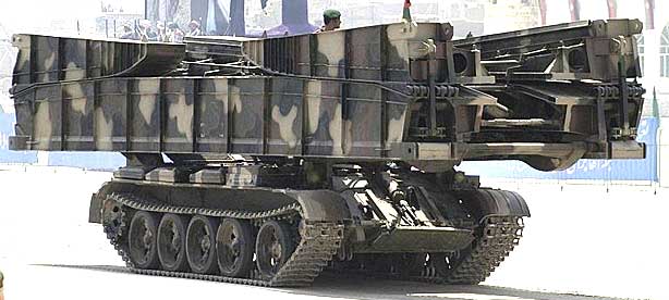
Танковый мостоукладчик МТУ-20 был принят на вооружение СССР в 1962 г., является действующим в настоящее время.
Фотогалерея

МТУ-20 (Объект 602) — советский бронированный танковый мостоукладчик. Разработан на базе среднего танка Т-55 в Омском конструкторском бюро транспортного машиностроения. Предназначен для наведения однопролётного металлического моста.
Разработчик: КБТМ
Производитель: Омский завод транспортного машиностроения
Год принятия на вооружение: 1962
Характеристики
| Боевая масса, т | 37 |
| Экипаж, чел | 2 |
| Время установки моста, мин | 5-10 |
| Длина моста, м | 20 |
| Мощность двигателя, л. с | 580 |
| Скорость по шоссе, км/ч | 54 |
| Запас хода по шоссе, км | 485-500 |
| Длина корпуса, мм | 9200, 11640 с мостом |
| Ширина, мм | 3270, 3300 с мостом |
| Высота, мм | 2000, 3400 с мостом |