145,73 Мб
Руководство по ремонту и эксплуатации Alfa Romeo Alfetta /
Формат: pdf
-
Год:
1991
-
Страниц:
277
-
Язык:
английский
-
Размер:
145,73 Мб
-
Категории:
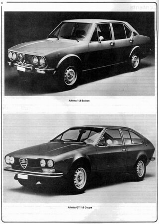
В руководстве по ремонту и эксплуатации Alfa Romeo Alfetta / GTV (1973-1987 г. выпуска), автовладельцы смогут узнать все о моделях автомобилей своей любимой марки.
32,92 Мб
Руководство по ремонту и эксплуатации Alfa Romeo 156
Формат: pdf
-
Год:
2009
-
Страниц:
274
-
Язык:
русский
-
Размер:
32,92 Мб
-
Категории:
В данном руководстве с максимальными деталями описано все, что связано с автомобилем Alfa Romeo 156. Здесь вы сможете найти рекомендации по эксплуатации автомобиля и конечно всевозможные его поломки, вместе с вариантами их решения.
53,9 Мб
Руководство по ремонту и техническому обслуживанию Alfa
Формат: pdf
-
Год:
1983
-
Страниц:
2576
-
Язык:
английский
-
Размер:
53,9 Мб
-
Категории:
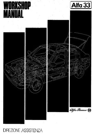
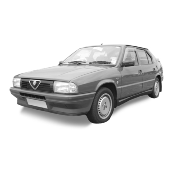
Данное руководство предназначено для владельцев автомобилей марки Alfa Romeo 33. Оно позволит владельцу самостоятельно и максимально быстро спланировать ремонт автомобиля.
16,7 Мб
Руководство по ремонту Alfa Romeo 33
Формат: pdf
-
Год:
1983
-
Страниц:
378+210
-
Язык:
английский
-
Размер:
16,7 Мб
-
Категории:
Руководство по ремонту Alfa Romeo 33 будет интересно всем владельцам этой модели. Вы сможете изучить инструкцию по данному автомобилю со всеми характеристиками и рекомендациями по эксплуатации.
603,93 Мб
Alfa Romeo: Все автомобили начиная с 1910 года
Формат: pdf
-
Год:
1978
-
Страниц:
901
-
Язык:
итальянский, английский
-
Размер:
603,93 Мб
-
Категории:
Книга «Alfa Romeo: Все автомобили начиная с 1910 года» понравится всем любителям данной марки машин. В ней подробно рассмотрены разные автомобили производившиеся заводом с 1910 года.
10,6 Мб
Руководство по эксплуатации Alfa Romeo 159
Формат: pdf
-
Год:
2008
-
Страниц:
331
-
Язык:
русский
-
Размер:
10,6 Мб
-
Категории:
Руководство по эксплуатации Alfa Romeo 159 будет полезно владельцам данного автомобиля, так как информация в нем представлена очень понятно и подробно. Данное пособие может пригодиться в дороге.
64,4 Мб
Руководство по ремонту Alfa Romeo 75 (с 1987 г. выпуска)
Формат: pdf
-
Год:
2005
-
Страниц:
141
-
Язык:
русский
-
Размер:
64,4 Мб
-
Категории:
Данное руководство для модели Alfa Romeo 75, составлено на основании работы и опыта сотрудников станций техобслуживания, с детальным описанием всех процедур ремонта и обслуживания автомобиля.

69,4 Мб
Руководство по ремонту и техническому обслуживанию Alfa
Формат: pdf
-
Год:
1997
-
Страниц:
158
-
Язык:
русский
-
Размер:
69,4 Мб
-
Категории:
Руководство для авто Alfa Romeo 164 станет любимым пособием для изучения своего автомобиля. В нем представлено огромное количество информации по обслуживанию и ремонту отдельных агрегатов и машины в целом.
Alfa Romeo
Права доступаВы не можете начинать темы |
Онлайн-руководства по эксплуатации Alfa Romeo 156/147/166
-
- Руководство по ремонту и эксплуатации 156
gospodinpavel » Пн сен 07, 2009 2:20 pm - 20 Ответы
- 53758 Просмотры
- Последнее сообщение Hatori

Вс май 12, 2019 9:03 pm
- Руководство по ремонту и эксплуатации 156
-
- eLearn for Brera
Komiss » Ср окт 26, 2011 11:45 am - 5 Ответы
- 12842 Просмотры
- Последнее сообщение Hatori
Вс май 12, 2019 3:27 pm
- eLearn for Brera
-
- Обсуждение online-руководств
Suspense » Пт янв 23, 2009 1:15 pm - 76 Ответы
- 47471 Просмотры
- Последнее сообщение Hatori
Вс май 12, 2019 9:12 pm
- Обсуждение online-руководств
-
- Руководство по ремонту и эксплуатации Alfa Romeo 156
anatolysilver » Ср окт 07, 2009 6:32 pm - 12 Ответы
- 24518 Просмотры
- Последнее сообщение Hatori
Вс май 12, 2019 9:04 pm
- Руководство по ремонту и эксплуатации Alfa Romeo 156
-
- Где можно приобрести р-во по ремонту 147? (DTE, E-learn)
Sayfulin_Ilya » Пт май 20, 2011 9:55 am - 8 Ответы
- 10956 Просмотры
- Последнее сообщение Hatori
Вс май 12, 2019 9:06 pm
- Где можно приобрести р-во по ремонту 147? (DTE, E-learn)
-
- Инструкция по эксплуатации 147 на русском
ольга » Ср фев 18, 2009 12:12 pm - 6 Ответы
- 15923 Просмотры
- Последнее сообщение Typhoon
Пт янв 20, 2017 9:16 pm
- Инструкция по эксплуатации 147 на русском
-
- Alfa 147 restyle owner’s manual
Suspense » Вс янв 25, 2009 1:31 am - 142 Ответы
- 118588 Просмотры
- Последнее сообщение Suspense
Чт янв 29, 2009 8:04 pm
- Alfa 147 restyle owner’s manual
-
- Alfa 166 restyle owner’s manual
Suspense » Ср янв 28, 2009 1:15 am - 273 Ответы
- 154793 Просмотры
- Последнее сообщение Suspense
Чт янв 29, 2009 5:53 pm
- Alfa 166 restyle owner’s manual
-
- Alfa 156 restyle owner’s manual
Suspense » Сб янв 24, 2009 2:19 am - 355 Ответы
- 235122 Просмотры
- Последнее сообщение Suspense
Вс янв 25, 2009 1:51 pm
- Alfa 156 restyle owner’s manual
-
- Alfa 156. Руководство по эксплуатации
Suspense » Чт янв 22, 2009 9:14 pm - 316 Ответы
- 201888 Просмотры
- Последнее сообщение Suspense
Пт янв 23, 2009 1:11 pm
- Alfa 156. Руководство по эксплуатации
Вернуться в Список форумов
Кто сейчас на конференции
Сейчас этот форум просматривают: нет зарегистрированных пользователей
Права доступа
Вы не можете начинать темы
Вы не можете отвечать на сообщения
Вы не можете редактировать свои сообщения
Вы не можете удалять свои сообщения
Вы не можете добавлять вложения
- Manuals
- Brands
- Alfa Romeo Manuals
- Automobile
- 33
- Workshop manual
-
Contents
-
Table of Contents
-
Troubleshooting
-
Bookmarks
Quick Links
models
ASSISTENZA TECNICA Lj%-@j.
P A 3 3 3 5 0 0 8 8 3 3 0 0
1 9 8 8
Related Manuals for Alfa Romeo 33
Summary of Contents for Alfa Romeo 33
-
Page 1
models ASSISTENZA TECNICA Lj%-@j. P A 3 3 3 5 0 0 8 8 3 3 0 0 1 9 8 8… -
Page 2
: “ W o r k s h o p M a n u a l r-33) lm] giardinettaH “ W o r k s h o p ‘… -
Page 3
FOREWORD This manuals is intended f o r models 1.3 s 1.5 TI 1.7 IE 1.7 + 1.5 4×4 lt complements the manuals referring to ihe corresponding ( A l f a models indicated here below: PA32 7900000000 “WORKSHOP MANUAL “WORKSHOP MANUAL “WORKSHOP MANUAL “WORKSHOP MANUAL… -
Page 4
QUICK REFERENCE INDEX COMPLETE CAR FUEL SYSTEM IGNITION, STARTING, CHARGING SYSTEM CLUTCH GEARBOX MOTION TRANSMISSION DIFFERENTIAL AND DRIVE SHAFT ASSEMB LY FRONT SUSPENSION FRONT AND REAR BRAKES STEERING SYSTEM REAR SUS.PENSION GR. 25 WHEELS AND TIRES GR. 28 ELECTRICAL SYSTEM BODY-SHEET METAL PANELS .DOORS HOODS… -
Page 5
COMPLETE CAR CONTENTS GENERAL VIEWS .., … 00-2 TROUBLE DIAGNOSIS SAND CORRECTION Dimensions and weights … . 00-3 ON IGNITION SYSTEM LE3.2 JETRONIC (1.7 IE with catalytic converter) . -
Page 6: General View
GENERAL VIEW October 1988…
-
Page 7: Dimensions And Weights
WITH TWO CARBURETORS WITH ONE CARBURETOR FUEL INJECTION COMPRESSOR 33 1.3 1.3 s 3 3 1 . 5 TI 3 3 1.5 a x a 1.7 IE 1.7 * 33 1.7 * 908.260 908.060 908.080 908.100 908.220 908.160 908.140 908.120 Identification number 908.061 A…
-
Page 8: Model Variation
MODEL VARIATION WITH TWO CARBURETORS WITH ONE CARBURETOR 3 3 1 . 5 a x a 3 3 1 . 5 TI 3 3 1 . 3 3 3 1 . 3 s Modal 5 door saloon Drive 908.260 908.060 label and label 9 0 5 A B…
-
Page 9
5 DOOR STATION WAGON Drive label 908.600 Identification No. 906.600 on identification label label Type approval No. bulkhead label 9 0 5 A 1 0 on intermediate bulkhead label 05379411 on cylinder 30168 30587 30508 from from Engine No. Type and serial No. from 0000001 0000001… -
Page 10
MODEL VARIATION Drive label 9 0 8 . 6 5 0 908.660 Identification No. label on identification label Type approval No. Serial No. 65407756 30558 from Engine No. Type and’sérial No. from 0000001 0000001 0000001 Tyre dimensions Rim dimensions (A) With ecological material and electronic injection engine for countries where antipollution regulations are in force (A) With ecological material… -
Page 11
Component FUEL TANK 6.5 (1.43) (1.43) (1.43) (1.43) FUEL RESERVE 4.57 (10.07) 5.25 (1.15) 3.6 (7.94) 4 (0.88) 3.6 (7.94) 4 (0.88) 3.6 (7.94) 4 (0.88) With ENGINE OIL SUMP 3.15 (6.94) 3.5 (0.77) 3.15 (6.94) 3.5 (0.77) 4.35 (9.59) 5 (1.10) Without filter (*) 3.15 (6.94) -
Page 12: Chassis And Body Maintenance
COMPLETE CAR CHASSIS AND BODY MAINTENANCE TECHNICAL DATA — INSPECTION AND ADJUSTMENT Axles and suspensions ô l tl…
-
Page 13
ENGINE WITH WITH lW0 TURBO COMPRESSOR WITH ELECTRONIC FUEL INJECTION CARBURETORS 5 door saloon 908.170 ( ;;;;NX;;, ( 908.150. / 905.180. / 908.160 label and label label bulkhead label 05411704 05410692 05411250 bulkhead label 305.58 305.58 from from from Type and serial 0000001 00001 A000001… -
Page 14: Maintenance Schedule
COMPLETE CAR MAINTENANCE SCHEDULE The following schedule is valid for the Italian market only ï 0 0 — 6 P A 3 3 3 5 0 0 8 8 3 3 0 0 /…
-
Page 15
Km/1000 O P E R A T I O N Notes 4 0 -5c 170 18( 190 200 Check terwon of and if necessary replace drive belts of: alternator. coolar pump and air~conditioner Replace drwe belt of alternator and air condltioner compresser (if fmed) C h e c k trghtness of au mtake syslem downstream from the air flow gaugl Replace fuel filter (where necessary) -
Page 16
COMPLETE CAR P A 3 3 3 5 0 0 8 8 3 3 0 0… -
Page 17
Km/1000 Notes 90 100~ 110 120 130 140 150 160 170 180 190 200 Check tension of and If necessary replace drwe belts of; alternator. coolant Replace drive bett of alternator and air conditroner compresser (If fltted) Replace camshaft drive belts Check fuel system for leaks Clean and check air filter element Check tvghtness of air mtake system downstream from the air flow gauge… -
Page 18
COMPLETE CAR The following schedule is valid only for those countries where antipollution regul,ations are in force P A 3 3 3 5 0 0 8 8 3 3 0 0… -
Page 19
COMPLETE CAR P A 3 3 3 5 0 0 8 8 3 3 0 0… -
Page 20
Km11000 OPERATION 10 20 Check sensor OI oxygen contents in exhaüsl gas Replace catalyst of exhaust gas be performsd more frequently when driving under particular stress codltions (1) A= 1000+1500 K m (sport driving) or on hilly roads Check oil level every 500 km and when refuelling be performed in any case every 12 months Check more frequently il driving in very dusty areas be performed in any case every 5 years… -
Page 21
COMPLETE CAR MAINTENANCE SCHEDULE programmed maintenance. OPERATION ine oil and oil filter check ti Replace oil in gearbox — differential (and rear differential in Check brake and clutch fluid levels Check axial an’d radial play of supercharger rotor shaft and Check idle r.p.m. -
Page 22
C O M P L E T E C A R OPERATION Note 1 6 0 1 8 0 2 0 0 Check tightness of fuel supply circuit Check fuel vapour emission contrai circuit (if installed) 26 Check air,filter cartridge Check tightness of air supply system downstream the air flow Replace fuel filter (where foreseen) Replace air filter cartridge… -
Page 23: New Identification Label
NEW IDENTIFICATION LABEL — — A L F A L A N C I A INDUSTRIALE S . P . A . VERSIONE-VERSION , N’ PER RICAfl8I 1 — Homologation code 5 — Serial number with relation to finished units: necessary when ordering spare parts, for identification of produc- tion or assemply plant and as reference for introduction 2 — Body marking…
-
Page 24
MODEL VARIATIONS (According to E.E.C. markings adopted on new identification labels) 1.3 s 3 1.9 l-l Body Drive LEFT LEFT LEFT on identification 905AP label vehicle type No. front cross member, right side, front cross member, right side, horizontal plane rised block 30566 30567… -
Page 25
CARBURETORS WITH ELECTRONIC FUEL INJECTION TURBO COMPRESSOR 5 DOOR SALOON Body left Drive leftlright leftlright on identification label vehicle type No. f r o n t c r o s s m e m b e r , right side, horizontal plane. -
Page 26
COMPLETE CAR RECOMMENDED FUEL AND LUBRIC&NTS 00-l 1 FUEL For coke@ engine functioning the specification is for premium grade or unleaded petrol: RON 2 95. For models with electronic injection and catalytic convertor only unleaded petrol to the following Octane Number (Research method) R.O.N. 2 95 (for Switzerland, Sweden versions) permit, the entry of only special filler spouts fitted exclusively on unleeded petrol pumps. -
Page 27
APPROXIMATE REFILL CAPACITiES 3 3 1.3 3 3 1.3 5 3 3 1 . 5 TI 1.7 IE 3 3 1 . 5 a x a 3 3 ‘1.7 + Measurement unit Liters Liters Components FUEL TANK FUEL RESERVE With filter- 4.57 ENGINE OIL SUMP Without filter… -
Page 28
ADJUSTMENT OF VALVE to the normal air flow. CLEARANCE Proceed as per [Alfa] except for the table referring to antifreeze fluid Alfa 33 1 . 7 except for the composition provided in “System tappets which engine ‘with hydrauliç… -
Page 29
1 Filter sup,port clamp Fuel inlet tube F u e l CHECKING &EL SUPPLY 1 Depression tube As for [-33) except for 1.7 2 Fuel pressure gauge electronïc ~ injection engines w h i c h 3 Throb damper require the following procedure… -
Page 30
COMPLETE CAR CHECKING OF EMMISSIONS CHECK A!D ADJUSTMENT OF IDLE, R.P.M. AND EXHAUST EMISSIONS a. Cleaning and replacement of air plugs, tables, cap, frotary rotor (see G r o u p 0 5 — transistorised ignition without contacts). c. Ignition timing. 2 Adjustment clip 3 Accelerator table sheath d. -
Page 31
COMPLETE CAR misalignment (40 mm Hg) between notwithinspecifiedvalueorincaseof’ Double carburetor models cylinders of the same carburetor then it e n g i n e tune u p a f t e r e n g i n e ; overhauling or after having cleaned or c a r b u r e t o r c a r b u r e t o r . -
Page 32
COMPLETE CAR obtain better CO exhaust emission adjustment it is necessary to operate The procedure is valid for 1.7 elec- measuring the values cylinder by cylinder using special service tool C, 3.0054 connected as follows: After adjustment of the idle r.p.m. following the above described pro- 2. -
Page 33
C O M P L E T E C A R D i s c o n n e c t t h e ’ w i r i n g ,of t h e 4 Start the engine and check that Check of ,e#hahst emissions Lambda sensor. -
Page 34
COMPLETE CAR CHECK ANiD ADJUSTMENT Put the vehicle on auto lift. 2. Working from en ine room, dis- a n d @ o f ‘For @m-l only lambda probe and disengage wiring from clips. Carry out the adjustment of the idle the g~ears in neutral and all ancillary U n l o c k ‘… -
Page 35
COMPLETE CAR W arm engine up to normal run- CHECK ON AIR SUPPLY a. D i s c o n n e c t p i p e 8 from dump ning speed. v a l v e DOWNSTREAM FROM THE air source to the with a gauge con- c. -
Page 36
COMPLETE CAR Fuel vapour s&on pipe Fuel vapour exhaust pipe Dump valve Compensation valve Fuel vapour filter. Fuel vapour separator Air delivery pipe 00-19 P A 3 3 3 5 0 0 8 8 3 3 0 0… -
Page 37
DIAGNOSTIC AND CORRECTIVE INTERVENTIONS ON LE3.2 JETRONIC I N J E C T I O N S Y S T E M for electronic injection 1.7 engines with catalytic converter only, O c t o b e r 1 9 8 8 PA 32 790084330 1… -
Page 38
COMPLETE CAR PA327900883301… -
Page 39
C O M P L E T E C A R THE ENGINE DOES NOT START Effect an electronic and functional test Check ignition system: integrity of igni- tion distributor, spark plugs and as- sociated tables. Check the efficiençy 6f inrake, tiucts, 00-23… -
Page 40
COMPLETE CAR THE ENGINE STARTS WITH DIFFICULTY 00-24 P A 3 3 3 5 0 0 8 8 3 3 0 0… -
Page 41
COMPLETE CAR IRREGULAR IDLE RPM Check for correct air flow. throngh Check that on a suckins ducts don’t troubleshooting from fuel system pressure and ignition system efficiency (spark plugs, take ducts Check G60 ground efficiency. Check minimum & maximum opening No. -
Page 42
COMPLETE CAR Check correqt functionality of the engine water tempqature sensor and relevant wiring by effpcting test No. 5 of electri- cal troublpshooting. Check valve clearance of engine timing. Check functionality of Lambda probe by e f f e c t i n g electrical troubleshooting Reconnect Lambda probe and check a CO value lqwering. -
Page 43
COMPLETE CAR for electronic injection 1.7 engines with catalytic convektor OF SYSTEM AND SENSORS AND ACTUATORS ASSOCIATED TO IT. P A 3 3 3 5 0 0 8 8 3 3 0 0… -
Page 44
Check G4 Fuse (15 Ohm) circuit p r e s s u r e presence between 2.8 bars and 3.2 bars. Check that negative terminal of pump is at ground. Check fuel filter and any possible duct NOTE: The pump must turn for a few seFonds even with the only key in the “MAR- CIA”’… -
Page 45
C O M P L E T E C A R Set hwltimeter to 200 Ohm FS. Check cohtinuitir between: Check also G60 grounds functionality. Set ~multimeter to 200 Ohm FS. 1 of CU connecter and terminal 1 of 1 of CU connecter and terminal 1 of u Restore wiring. Restore wiring. -
Page 46
COMPLETE CAR Set molfimeter fo 200 Ohm F.S. Check setting and efficiency of mini- mum opening switch. Check the ~existance’of a resistance value lower than 10 Ohm. Press accelerator and check an in- Check wiring continuity between: Restore wiring. and ground; and CU connecter pin 15. -
Page 47
C O M P L E T E C A R TEST No. 5 I CHECK ON ENGINE WATER TEMPERATURE SENSOR (CU PIN . Disconnect electronic CU connecter. Check wiring continuity between: Check between pin 6 of CU connec- brown wire on S7 temperature as pe,r curve.
 -
Page 48
COMPLETE CAR Disconnect qecfors removmg relevant Read from~8 to 5 Ohm. , single injecter. that Will result between I 14 and 18 Ohm. Checkon singleconnectorsof injectors pins be — Repairwiring fautt and the other to pin 3 of CU connecter. 00-32 P A 3 3 3 5 0 0 8 8 3 3 0 0… -
Page 49
— Set multimeter to 20 V F.S. n e c t e d . Check wiring continuity between Check presence of + 12 V between ter- Check integrity of fuse No. 2. S12.b relay shoe terminal 85. and With ignition key on RUN position, groud G60. -
Page 50
COMPLETE Set multimeter to 20 V F.S. Check G4 (7.5 A) fuse integrity. resistance r e s i s t a n c e termlnals of Lambda p r o b e . resistance preheating B Replace Lambda probe group. tionality maa,suring a value be- tween 3 Ohmland 20 Ohm. -
Page 51
COMPLETE CAR INJECTION — IGhiITION W’IRISNG l3IAGRA.M for electronic injection 1.7 engines with catalytic convertor only… -
Page 52
C O M P L E T E C A R ~DIAGNOSTIC AND CORRECTIVE INTERVENTIONS ON LE3.2 JETRONIC for electronic injection 1.7 engines without catalytic converter only PA 42 790088330 1 October 1988… -
Page 53
COMPLETE CAR P A 3 2 7 9 0 0 8 8 3 3 0 1 O c t o b e r 1 9 8 8… -
Page 54
THE ,ENGINE’DOES NOT START O c t o b e r 1 9 8 8… -
Page 55
Check air su$plyI system for leaks In WITH COLD ENGINE With cold engine, 2 mins. after ignition throttle extra ‘air valve pipe and verify that RPMs at minimum diminish noti- Replace extra’air valve. With hot engine, 3 mins. after ignition With engine’running verify presence of throttle extra air valve pipe and verify + 12 V on connecter on wiring slde of… -
Page 56
EXCESSIVE FUEL CONSUMPTION’ lant temperature sensor and relative wirlng Check for correct air flow through throttle procedures for injection system. Check that there are no leaks in the air intake Ckeck electromtector trghtness. ANOMALIES IN ACCELERATION AND BURSTS JN RELEASING Effect troubleshooting procedures for igni- Check correct fuel system pressure and shooting procedures for inlection system. -
Page 57: Troubleshooting Procedure
COMPLETE CAR TROUBLESHOOTING PROCEDURE ~ FOR INJECTION SYSTEM ~ for electronic injection 1.7 engines without catalytic converte; NOTE: OF TH~E SYSTEM AND SENSORS AND ACTUATORS ASSOCIATEb TO IT. IF AT.~THE END OF. TESTS THE ANOMALY SHOULD REMAIN, IT WILL BE NECESSARY TO NESS OF AIR INTAKE DUCTS, ETC.
-
Page 58
COMPLETE CAR Check G4 Fuse (15 A) pump terminals. Check fuel’ system pressure. pressure presence between 2.8 bars and 32 bars. Check that negative terminal of pump is Check fuel filter and any possible dUCt NOTE: ~ at ground. throttlings. The pu’mp,must turn for a few seconds , YES Check efficiency of pressure gauge. -
Page 59
COMPLETE CAR Disconnect !Injection CU connecter. Restore wiring between: Check conti@ity petween: Check also G60 grounds functionally. TEST No. 3’ — CHECK CONNECTION TO RPM SIGNAL’(CU PIN 1) Disconnect Iljection CU connecter. Check wiring contlnuity between pin 1 of Restore wiring. CU connecter’… -
Page 60
COMPLETE -CAR TEST No. 4 — CHECK ON MIN. 81 MAX. THROTTLE OPENING’SWITCH (CU PIN 15 AND 14) Set multumeter to 200 Ohm FS. K e y r e m o v e d . 1 . ‘ l Check setting and efficiency of mini- Check the existante of a reslstance Chech wiring continuity between: black wire bn S6 swifch connection… -
Page 61
COMPLETE CAR TEST No. 5 — CHECK OF ENGINE COOLANT TEMPERATURE SENSOR (CU PIN Set multimeter to 20 KOhm FS. sor; Replace S7 sensor TEST No. 6 October 1988… -
Page 62
COMPLETE CAR TEST No. 6 — CHECK OF ELECTROINJECTORS CIRCUIT Set multimeter to 200 Ohm F.S. Disconnect electroinjectors removing Check resistance between CU connec- Replace faulty injectors. relevant connectors. Measure resistance on terminal of every single injecter, that Will result between 14 and 18 Ohm. -
Page 63
COMPLETE CAR Disconnect infeqtron CU conpector. With ‘igniiion key on RUN position, Check Integrity of fuse check presence of + 12 V between CU With ignition key in RUN position, With ignition key in RUN position, Check presence of + 12 V between ter- check presence of +12 V between ground. -
Page 64
C O M P L E T E C A R TROUBLESHOOTING PROCEDURi FOR IGNITION SYSTEM for electronic injection 1.7’engines without catalytic cbnverter NOTE: P A 3 2 7 9 0 0 8 8 3 3 0 1 October 1988… -
Page 65
THE ENGhE DOES NOT START Check the presence of voltage to spark Check vehicle, system functionaiity (eg: Set multimeter to 20 V F.S. Key in RUN position. nal 15 and starting block; starting block Check presence of + 12 V between igni- supply and functionality). -
Page 66
Restore wiring.- Check wiring continuity (after having cli- sconnected ignition CU (N20) connecter and ignition CU (Nl) connecter between: . ignition module conneètor pin 3 and ignition CU pin 1 tion module connecter pins 5 and 6 white wire on ignition coi1 terminal 1. Check ignition coi1 (A6) functionality ve- Replace ignition coil. -
Page 67
ADVANCE ‘VARIATION CHECK TEST No. i Connect stroboscopic gun and check: the piescribed value; value. Disconnect ignition CU connecter (N20). Wlth engine’ running steady disconnect Check wiring continuity between igni- engine coolant temperature sensor con- tion CU co.nnector pin 7 and sensor brown-white wire. -
Page 68
Discinnect minimum and m a x i m u m Check wiring continuity between: thrdttle opening switch connecter ahci . connecter pin 16 of minimum and ma- read advance value. ximum throttle opening switch S6 and ground G60. 16 (black wire) and check an advance va- . -
Page 69
COMPLETE CAR for electronic injection 1.7 engines without catalytic converter only… -
Page 70: Front
A + B = 490 + 245 = 735 N Vehicle static loading arrangement (1 j (50 + 25= 75 kg) A — — 2:’; Front wheel alignment B = +33 t;s B = 27?$’ B = 41:‘s” Rear wheel alignment M-H = 2 f 2…
-
Page 71
COMPLETE CAR SPECIAL SE#RVICE TOOLS Refer to Tool number Tool name A.4.0146 Tool for suspension height check A.4.0149 Tool for suspension height check Probe for suspension height check A . 4 . 0 1 5 0 (to be used with A.4.0146 — A.4.0149 (to be used with A.4.0146 — A.4.0149) A.4.0206 (to be used with A.4.0146 — A.4.0149) -
Page 72
~INSTALLATION ….. . . OI-2 Cylinder heads . .‘….01-14 Pistons and connecting rods . -
Page 73
ENGINE MAIN MECHANICAL UNIT D IINSTALLATION These procedures are for electronic injection ,A.7 engines b. Disgonnect the ignition distributor b. Disconnect hose 0 from pressure cap @ and remove it complete with 1.7 LE. with ca’talytic converter leads from engine. 7. -
Page 74
3 Alr~flowllnjectlon CU sensor 32 Supplementary air feed tubs 15 Fuseholder box 4, Coollng system breather pipes 33 Idle regulatlon by;pass tube 19 Ploe of clutch control hvdraullc 5, Akflow sensor fixlng screws 34 Collant dellvery slseve to radlator 6 Alr!flow sensor support… -
Page 75
E N G I N E M A I N MECHANICAL UN’1-i ” 1.7 IE with catalytic converter 3 Odometrlc sensor table 1.7 IE without catalytic converter distributor 7 Engine coolant temperature 9 Col1 low.voltag& table 10 Electrlc fan tables for thermal c o n t a c t c o n s e n t 11 Foglamps cablbs… -
Page 76
12. Loosening nut of engine central c. Remove the discharge mainfolds support For folhwing’removals, refer to figure drawing from bottom the wirlng of at page’O#l-4. lambda probe, previously disconnec- With reference to the following figure t e d . loosen bolt to the body without removing it. -
Page 77
E N G I N E M A I N MECHANICAL UFflT’ VIEW OF UNDERPART OF VEHICLE — LOCATION OF ,COMPONENTS 1 Screws fixing cross member to body 10 Engine oil drain plug 2 Cross member to right strut connecting bolt 11 Reverse light table 12 Muffler central silencer 5 Coolant drain plugs… -
Page 78
4 Side rod (engine antishock bar) . differential shafts (in ‘engine 5 Front screw 6 Rear screw 33 + 36 N.m rear support and the engine front sup- port are not respectively upwards and longitudinally preloaded. 2. Reinstallation of reverse light table and of exhaust pipe e. -
Page 79
ENGINE MAIN MECHANICAL IdIT 3. Reassembty of electrical tables h. Remount hood. Pipe @ from supply manifold @ . i. Remount the battery negative termi- Pipe @ , from throttle body and pi- nal. Lower the auto lift and, with reference pe 0 fro,m pneumatic gauge on ignition distributor 0. -
Page 80
ENGINE MAIN :MECHANICAL UNIT 6. Completion of reassembly I N S T A L L A T I O N 11. Removal of electrical tables 1.7 IE without catalytic converter a. R,econnect injectionlignition wiring Operatè as described at step 11 page in reverse order to that described un- ‘01-5 with reference to Fig. -
Page 81: Engine Maintenance
ENGINE MAIN MECHANICAL UNIT: ,‘~ GEARBOX-DIFFERENTIAL OIL d. Bleed the clutch hydraulic system ENGINE OIL and top up said circuit (as per Alfa 33 — Type: Group 12). Type: e. Start the engine and, when at nor- AGIP Rotra MP SAE 8OW/90…
-
Page 82
1 Electroinjectors~ 2 Fuel supply manifold 3 Lifting brackets 4 Supply manifold 5 Fuel puise damper 6 Fuel pressure gauge 7 Intake manifolds 6 Supplementary air solenoid valve 9 Gasket 10 Coolant temperature sender (for indicator) 11 Gasket 13 Dipstik 14 Single contact min. -
Page 83
E N G I N E M’AIN M E C H A N I C A L U N I T ( 0 . 5 15 Valve guide 1 Jockey puylley 3 Right tlmin pulley 19 Seal cap 4 Timing belt rear caver 19 Springs 5 Englne front caver 6’… -
Page 84
Main bearings Compression rings Woodroff key Thrust half-ring Bush Engine oil drain plug Seal ring Main bearing caps P i s t o n Connecting rod Connecting rod bearings Washer Crankshaft… -
Page 85
PRELIMINARY (1) Unscrew and remove spark plugs from cylinder heads. (2) Loosen distributor @ securing Remove #drive unit from car ac- nut @ and withdraw distributor from rear caver. 2. Remove Qearbox — differential unit and clutcq uni? from engine according t o ‘proc&d,ures: S e p a r a t i o n a n d As- 3 Fuel pressure gauge Ignition distributor… -
Page 86
ENGINE MAIhI ‘MECHANICAL UNIf 9. P’ropeed as per (Alfa331 from step to end, but for step 21 “Re- tem union. move Cylinder Heads”, which should be modified as follows: (1) Unscrew the six screws @ which (2) Remove heads ‘along with cam- thermostat and union ‘0 shaft Supports and the gaskets on en- gine bldck. -
Page 87
Mastics rclass: 3522-00040 heads and block. Loctite 601 (green) Before applying ‘sealants eliminate degreasing the surfaces. stated O p e r a t e per c-33) taking into account Cylinder block rear caver 2 Hydraulic tappets cup the following: PA333500883300… -
Page 88
ENGINE MAIN MECHANICAL U~NIT (2) Set the camshaft in rest position (no ca” engaged; valves closed). shaft sipport on the cylinder ,block, and ~ifis&the appropriat’e gasket. (1) Fit~ camshaft drive pulleys and Timing belt rear guard Timing belt rear qover 2 Right-hand timing pulley 2 Left timing pulley torque being caeeful, at the same time,… -
Page 89
Thermal contact screw on ure, tightening it to specified torque. ~ right head : Tightening torque 33 + 41 N-m straightener ~itself. Pressure switch 33 + 41 N.m (4) Connect thermostat to right intake (3.4 i’… -
Page 90
ENGINE MAIN MECHANICAL UNiT 30. ,Retiount injectors on intake 27. Fitloil filter by manually tightening (4) Adjust belt tension according to it and insert dipstick. specified value and then lock bolts manifolds, replacing relevant O-rings, and fix lfuel manifold. Load: 8 Kg 28. -
Page 91
1700 1350 1 5 0 0 305.58 305.58 A Features Otto 4 stroke Cycle 4 horizontally opposad Numbers of cylinders and arrangement Right head Cylinder identification 84 x 67,2 8 7 x 7 2 Bore — Stroke 8 7 x 7 2 80 x 672 80 x 67.2 80x 59… -
Page 92
CAMSHAFT SYSTEM Unit: mm (in) Single carburetor engines Double carburetor engines 1350 1350 1500 1200 * 305.87 305.88 3g5.85 305.86 L E F T S U P P O R T 546.232 Camshaft 545.766 035 + 0,40 Exhaust 0.45 + 0.50 ~ Right support Left support on camshaft supports… -
Page 93
For countries where antipollution regulations are in force… -
Page 94
ENGINE MAIN MECHANICAL QNI,T ~ Unit: mm 1700 1500 305.8% 305.85186187 84,00 f 84.01 Glass A 87,000 + 87,010 84.01 + 84.02 87,010 f 87,020 80.01 +60.02 Class B 87,020 i 87,030 60.02 t80,03 Class C 84.03 G84.04 80.03 C80.04 87,030 + 87,040 87,040 f 87,050 87,200 f 87,210… -
Page 95
Unit: mm (in) 1700 1200-1350 1700 A 1500 305.50 (5-6) 305.85 (1) 305.58 (6) 305.88 (3-4) 305.58 (5-6) 305.86 (2-3) Inspection data 305.87 (2-3) Pistone Mondial Pistone Borgo 86,950 + 86,960 79,960 + 79,970 8 3 , 9 6 0 + 8 3 , 9 7 0 8 6 , 9 6 0 + 86,970 8 6 , 9 5 0 t 8 6 , 9 6 0 Class B (Pink) -
Page 96
Unit: mm (in) Inspection data 1200 * 1350 1500 1700 305.85 305.86 — 305.87 305.88 305.50-305-305.58 First compression ring 1,478 ~1,490 1,478 + 1,490 Ring thickness “b” Second compression ring 1,728 + 1,740 1,728 + 1,740 3,978 f 3,990 2,978 + 2,990 First compression ring 0.30 045 (2) -
Page 97
‘ENGINE MAIN MECHANICAL UNIT Unit: mm (in) 1700 1350 1500 1200 305.50 — 305.58 305.86 — 305.87 305.88 305.85 P i n diarndter “a” P i n — p i s t o n slack OI-24 1988… -
Page 98
Unit: mm (in) Inspection data 1350 1500 1700 305.85 305.88 52,696 + ,53.708 Unit: mm (in) Inspection data Standard 1,956 + 1,962 2,083 +:2,089 2,210 +‘2,216 2,337 + 2,343 If thd connecting rods are completely removed. usa post-modificatin ones (Std No. 542 128) If the connecting rods are partially replaced it is still possible to mount pre-mobification’ones (Std. -
Page 99
ENGINE MAIN’ MECHANICAL Unit: m (in) Engine 1 3 5 0 a 500 1700 1200 * 305.85 305.88 with flywheel-to-cranksheft support face (as read et 0.02 Maximum outof-flat of driven plate contact face The quamtity of material removed bv grinding dimension “b”, must be the seme both on clutch driven plate contact fece and on the that dimension “a”… -
Page 100
ENGINE MAIN MECvANICALs UNI$ Taper A — B Gear tooth beginning line Unit: mm (in) Inspection date 1200 * 1’350 1500 1700 305.85 305.86187 305.88 Standard 59,944 + 59,957 59,690 + 59,703 59,436 f 59,449 Undersize 59,182 + 59,195 58,928 + 58,941 4 t h 49,984 ‘: 49,992 Blue… -
Page 101
ENGINE MAIN MECHAhlICAL U’NiT Unit: mm (in) E n g i n e Inspection data 1200 * 1 3 5 0 1500 1700 3 0 5 . 8 5 305.88 Max. miialignment betwaen tha centrelines of the M 0 . 0 3 pairs of crankpins and the journals centreline Rear crankshaft bush diameter “b”… -
Page 102
ENGINE MAIN MECHA~WCA~ LJNIT -b—l- Unit: mm (in) E n g i n e 1700 1200 * 1350 1500 305.88 3 0 5 . 8 5 35,015 + 35,040 35,015 +35,040 F r o n t Bore of cbmshaft journal bearing 48,000 + 48,025 46,500 f 46,525 Central… -
Page 103
Central Rear Front U n i t : m m Engine with electronic ignition Double carburetor engines Inspection data 1200 * 1350 1350 1500 1700 1700 1700 305.85 305.86 305.87 305.50 3 0 5 . 5 8 305.58 Intake Cam height Exhaust 8.50 Front “a”… -
Page 104
Unit: mm (in1 Cylinder head Engine 1350 1350 1500 1700 305.87 305.88 305.50 305.58 305.85 13,000 + 13,018 Standard 13,050 + 13,068 Valve guide O.D. “a” 13,064 + 13,082 Spare 8,013 + 8,031 Diameter of valve guide bore “b” Diameter of saating for valve Stern sealing cap. “f”~ Valve guide protrusion “8”… -
Page 105
Unit: mm (in) Engine Inspection data 1350 1500 1700 1200 * 305.86 305.87 305.88 305.50 — 305.58 305.85 7,985 + 8,000 Intake Valve stem diameter “a” 7,968 + 7,983 Exhaust 38,00 + 38.20 Intake Valve head diameter “b” 33,00 + 33,20… -
Page 106
ENGINE’ MAIN MEi2HANICAL U~lilIT Unit: mm (in) Engine Inspection data 1200 * 1350 1350 1500 1700 305.85 305.86 305.87 305.88 39.0 Exhaust 1.07 + 1.37 Intaka Exhaust Valve seat top surface limit angle “a” 120″ Valve setit rnating surface limit angle “fi” Intake Valve se+ in’ner face limit angle “y”… -
Page 107
ENGINE MAIN MECHANICAL UNil? I Unit: mm (in) Engine inspection data 1700 1 7 0 0 1200-1350-1500 305.58 305.50 305.85 — 305.86 — 306.88 305.87 0,040 + 0,060 Standard 0.03 +0,06-(l) 0,040 + 0,066 Oversize 0.04 + 0,066 (2) 0,035 + 0,057 (1) 0,045 f 0,077 0 , 0 3 5 First compression ring… -
Page 108
AGIP SINT 2000 lOW40 Std. No. 3631 — 69352 Std. No. 3631 -‘69353 SHELL Super Plus GRINDINGS A s f o r C-33) Measurement unit 66.5 i 63.3 6.6 i 6.5 1 4 . 7 + 2 3 . 5 1.5 + 2.4… -
Page 109
E N G I N E M A I N MECHANICAL UNIT ~ A T I O N S F o r d i e s e l engines only ” As for E N G I N $ Features Engine t~ype 4 — Stroka Diesel 3 in line… -
Page 110
ENGINE MAIN MECHANICAL UNIT TIMING DATA (1) 129.958 Alfa Romeo Part No. 0.30 (0.012) Intake 0.30 (0.012) Exhaust Intake Normal cam lift 7.64 (0.301) Exhaust T.D.C. Opens (B.T.D.C.) “ ” I n t a k e Closes (A. 8. D. C.) Intake phase angle “… -
Page 111
E N G I N E M A I N MECHAiUICAL UNIT~’ ~ Cylinder liners Unit: mm (in) Engine 1 8 0 0 V M 8 2 A 9 2 . 0 0 0 t o 9 2 . 0 1 0 Liner bore “a”… -
Page 112
ENGINE MAIN Compression rings Unit: mm (in) Engine Inspection data 1 8 0 0 VM 82A 1 st compression ring 2.075 to 2.095 (0.0817 to 0.0825) 2nd compression ring 1.978 to 1 .s90 (0.0779 to 0.0783) 3.978 to 3.990 (0.1566 to 0.1571) 1 st compression ring 0.40 to O.b5 (0.0157 to 0.0256) 0.25 to 0.45 (0.0098 to 0.0177) -
Page 113
ENGINE MAIN MECHANICAL UNIj- ; Pistons~ (with insert) U n i t : m m ( i n ) 1800 Inspection data VM 82A Grade A 1st coypqession ring groove height “b” 2.060 to 2.080 (0.0811 to 0.0819) 2nd cdmpression ring groove height “c” 4.020 to 4.040 (0.1583 to 0.1591) 30,002 + 30,007 0 . -
Page 114
ENGINE MAIN M~ECHANICAL $lT~ Ovality X-Y Taper D-E Unit: mm (in) Engine Inspection data 62,995 f 63,010 63,005 + 63,020 69,985 + 70,000 53,940 953,955 Standard Crankpin diameter “6” 1st’ 53.670 + 53,690 Undersize 53,420 + 53.440 Front and intermediate 2.7 +3 main journals 2.7 +3… -
Page 115
Rear bearing ‘inner dia. “E” in bearing split ring 69.800 to 69.825 (2.7480 to 2.7490) 69.550 to 69.575 (2.7382 to 2.7392) Rear bearin,g housing shoulder distance “F” 33.060 to 33.130 (1.3016 to 1.3043) Crankshaft ;abutment flange thickness “G” 7.90 to 8.10’(0.3110 to 0.3189) Standard 2.311 to 2.362 (0.0909 to 0.0930) -
Page 116
E N G I N E MAlN~MECHANICAL~UhjIT Unit: mm (in) E n g i n e Inspection data 1800 V M 8 2 A Connecting rod small end bearing bore “a” 30.030 to 30.045 (1.1823 to 1.1829) 34.089 to 34.129 (1.3421 to 1.3437) Bush housing inner dia. -
Page 117
ENGINE MAIN~ b/iiCHANICAL U~NIT ~ Unit: mm (in) Engine Inspection data 1800 VM 82A 0.625 to 0.045 [(0.984 to 1.772).10”] Wear limit 0.5 (19.68.1 03) 1 st compression ring 2nd compression ring 0.070 to 0.102 [(2.756 to 4.016,.10-3] 0.030 to 0.062 [(1.181 to 2A41j.10-3] 6,006 + 0,017 0.034 to 0.055 [(1.338 to 2.16E~>:lO-~] Wear limit… -
Page 118
DESCRIPTION ……04-2 . Injection system Jetronic LE 3.2 ..04-2 tightness . -
Page 119: Fuel System
D E S C R I P T I O N ‘ ~ . ~ For electronic injection 1.7 engines’ troinjectors for this time. Since the dif- air intake temperature ference between fuel pressure and air engine coolant temperature quantity of air taken in by the en- pressure in the manifold is mantained constant by a regolator, the quantity gine…
-
Page 120
FUEL SYSTEM AIR, FUEL, FUEL VAPOU’R SYSTENl CHART October 1988… -
Page 121
INJECTION SYSTEM WIRING DIAGR’AM P A 3 2 7 9 0 0 8 8 3 3 0 1… -
Page 122
An ete,ctroinjector consists essentiaffy FUEL PRESSURE REGULATOF) of a The fuel under pressure enters the lo- wer chamber of the regulator and acts FUEL PUMP needle and the needle. The tore of the on a membraneiwhich, overcomin~g the moving magnet is in one piece with The pump is of the rotating type with action of a spring, rises togheter with the needle which is pressed against… -
Page 123
FUEL SYStEM a full load contact. In this way a is sent to the electronic CU when the greater resistances, due to friction, air-petrol ratio according to the requi- rements of th,ese engine conditions. When the aceelerator is released the fuel supply is tut off by means of the minimum throttle opening switch. -
Page 124
parator @ which-is arranged in such The iollowing components are fore CATALYTIC MUFFLER a way as to permit the return of con- A catalytic converter is mounted in the converter. densed fuel to the tank. exhaust system with the purpose of The tank has a sealed filler cap to pre- reducing exhaust emissions. -
Page 125
1 Fuel vapour intake tube 2 Vacuum pressure tube for dump valve 7 Fuel :iapour separator control 3 External air delivery tube 4 Fuel tank 10 Fuel !vapour filter 5 Fuel vapour breather; hose When painting in furnace at tem- low voltage tables, for testing. -
Page 126
FUEL SYSTEM 1 Air filter 2 Air flow sensor 3 Corrugated sleeve 4 Throttle body 5 Air inletloutlet hose from supplementary solenoid valve 6 Metal fitting 7 Oil vapour exhaust hose 8 Vacuum pressure intake tube 9 Fuel vapour circulation pipe 10 Fuel vapour fllter 11 Air manifold 12 Extra air solenoid valve… -
Page 127: Air Filter
FUEL SYSTEM AIR FLOW SENSOR AIR FILTER The body of fhe air flow sensor incor- porates the blectronic control unit for the pilotiqg of the fue! injection sy- 1. Disconnect the multipolar connec- tor @ from the body of the sensor 2.
-
Page 128: Throttle Body
FUEL SYSTEM 4. Remove plastic caver @ . fixing starter 0 and remove it. and battery negative terminal a. Make sure that the engine is cold, then start and throttle several times outlet tube 0 of solenoid valve @ tinues ito fait with the passage of time (at rooin temperature of 20°C no fall in 2.
-
Page 129
FUEL SYSTEM 6. Disconnect depression tube 0. 7. Unscrew four fixing screws and re- move throttte body @ and gasket Proceed to assembly operating in re- f r o m supply~,manifold @ . verse order in respect to removal, fol- lowing these instructions: The two upper screws fix braket @ Fit a new gasket between throttle… -
Page 130
FUEL SYSTEM 10. Unscrew three nuts @ on each ASSEMBLY 3. Remove lock ring 0 and discon- manifold end and remove manifold with gasket 0. 4. Disconnect wiring @. Proceed to assembly operating in re- 5. Dfsconnect tube @ from throttle verse order in respect to removal, fol- lowing these,‘instructions: 6. -
Page 131
11 Filler pipe 6 Ground table 12 Fuel pump 1 2 E l e c t r o i n j e c t o r s Pressure gauge 7 Fuel tank fixing st!ap 13 Excess fuel recovery pipe 8 Fuel level gauge assy 3 Fuel filter 14 Pulsation damper 9 Level gauge fixing screw… -
Page 132
DAMPER 2. Disconnect electroinjectors connec- tors one,by one; each time detect CO percentage at exhaust and check that value remains constant at all checks. REPLACEMENT REPLACEMENT 3. If this is not the case, locate the 1. Loosen clamps and disconnect fuel 1. -
Page 133
4. Effect assembly operating in rever- FUEL PRESSURE se order in respect to removal. REPLACEMENT WARNING: Operate carefully: fuel system coud be pressurized. Unscrew the two connecting fittings 1 Fuel supply ihose 2 Electroinjectors supply wiring supply hose @ to regulator 2. -
Page 134
FUEL SYSTEM FUEL VAPOUR EMISSION CHECK SVSTEM For electronic injection 1.7 ,engineq, with cataly;tic conve’rtor P A 3 3 3 5 0 0 8 8 3 3 0 0… -
Page 135
FUEL SYSTEM 2. Disconnect’ valve @ from fuel recovery tube circuit. SEPARATOR trunk. 2. Loosén Aamps and disconnect tubes 0~ and @ from separator. 3. Unscrew t h e t w o s e c u r i n g n u t s indicated in the fig,ure and remove the s e p a r a t o r ~ @ 1 Retainer valve… -
Page 136
3. For assembly, operate in reverse or- 1 External air tube 2 Fuel vapour intake tube der in respect to removal. 3 Fuel vapour Inlqt tube 4 Fuel vapour fllter CALIBRATIONS AND ADJUSTM~ENTS For electronic injection’ 1.7 engines only 1,. Loosem clamp and disconnect slee- 5. -
Page 137
FUEL SYSTEM 3. Rotate throttle 60° f 4’ and check Whenever detected values are higher than maximum specified values, lowing resistances on male connec- tors, with tester. if they are faulty, replace them. screw 0~ u?til speciofied flow value With accelerator throttle open by i s o b t a i n e d . -
Page 138
FUEL SYSTEM For electronic injection 1.7 engines’ only 4. Remount CU operating in reverse or- ELECTRONIC 2. Unscrew four fixing screws shown der ‘in respect to removal, then apply a in figure (one of which is under seal new seal cap (in screw Seat). If CU has cen’tage at exhaust (see: Calibration and Setting). -
Page 139
1 Gaskets 10 Rear muffler 6 Catalytic muffler 2 Front manifolds 11 Clamp fixing bolt 7 Gasket 3 Nut 12 Clamp 8 Lambda probe 4 Plug for CO% sampling upstream catalytic muffler 13 Nuts fixing manifold to heads 9 Buffer 5 Support ring… -
Page 140
F U E L S Y S T E M MANIFOLDS AND MUFFLERS Referring to the figure proceed, with replace jhem. 2. Remove rear muffler as,foli,qws: “Group 00 — Vehicle Maintenance ( 1 ) L o o s e n clamp @ connecting Chat?‘. -
Page 141
SUPPORT RINGS a. Always fit new gaskets between (3) Unscrew nuts @ securing cata- manifold flanges and cylinder heads, lytic muffler @ and exhaust manifold and on flange between muffler and ex- Verify integrity of support rings and haust manifold. (4) Free! cetalytic muffler @ support replace them if necessary. -
Page 142
FUEL SYSTEM ~ OR CATALYTIC MUFFLER Integrate troubleshooting of basic manual as follows: Corrections Probables causes Troubles Clean or replace spark plugs Scaling of one or more spark plugs C l e a n o r r e p l a c e Replace Accelerator not set properly’… -
Page 143
FUEL SYSTEM -DATA AND ~SPECIFICATIONS SERVICE For electronic injection 1.7 engines o$ym Litres (corresponding to position A: closed,throttle) ‘(corresponding to position 6,: open throttle) Unit: T e i m i n a l s 3-18 completely closed 1 Seal 2 Adjustment screw 3 Depression intake fitting Reading 400 + 10 N scale… -
Page 144
Clearance between throttle control and accelerator table pawl (with accelerator pedal fully pressed) 950 +‘O” muffler with lambda probe disconnected CC percentage at dle rpm % i n v o l . outlet o u t l e t Fuel !supply system Working pressure (1) 2 8 0 + 320 (2.8 + 3,2;… -
Page 145
c e n t r a l Position 1st Carb. 2nd Carb. Diffuser Centering device 12189.01 Main jet Main air jet corrector Diffuser F 6 8 9 1 6 4 . 0 1 Idling jet Idling air corrector Progression holes 100 — 140 140 120-120 120 130… -
Page 146
1500 Displacement 305.88 305.50 ALFA ROMEO 580.778 — 580.777 580.776 — 580.775 546.860 — 546.861 546.858 — 546.859 Part No. CARBURETOR T w i n D e l l o r t o T w i n W e b e r… -
Page 147
FUEL SYSTEM SPECIAL SERVICE TObLS For electronic injection 1.7 engines only D e n o m i n a t i o n Key for plug of exhaust gas Fitting for exhaust gas sampling of Lambda probe Buffer for air flow checking 0 4 — 2 6 to be used with C.2.00% 0 4 — l 9… -
Page 148
IGNITION, STARTING, CHARGINGN SYSTEM C O N T E N T S 05-2 IGNITION ……Checks and inspections ..,..(*) Reassembly . -
Page 149
Technical data and inspections 1700 1700 1350 1500 1700 Electr. Electr. injection 305.85 — 305.86 305.87 305.88 305.50 Engine injection 305.58 305.58 A Alfa Romeo 581.293 581.292 581.363 581.291 548.604 Bosch Bosch Bosch Bosch Bosch 0.237.601 0.237.601.021 0.273.601 ,017 0.237.601.014… -
Page 150
1 2 0 0 3 0 5 . 8 5 1 3 5 0 3 0 5 . 8 6 Automatic ,advance curve 2 5 0 5 0 0 1 0 0 0 2 5 0 0 3 0 0 0 Vacuum pressure corrector curve I L ! ! ! I I I I… -
Page 151
DISTRIBUTDR ADVANCE CURVES 1350 — 395.87 1350 — 305.88 A u t o m a t i c adtiance c u r v e 1 0 0 0 1 5 0 0 3 0 0 0 Distibutor r.p.m. Vacuum pressure corrector curve 4 0 0 6 0 0 3 0 0… -
Page 152
IGNITION, STARTING, CHARGING SYSiEM DISTRIBUTOR ADVANCE CURVES ENGINE 1 7 0 0 — 3 0 5 . 5 0 Automatic advance curve D i s t i b u t o r r . p . m . Vacuum :Pressure corrector curve t i i i i i i i i , i i in-i i 4 0 0 2 0 0… -
Page 153
1 7 0 0 — 3 0 5 . 5 8 P n e u m a t i c advance curve P A 3 3 3 5 0 0 8 8 3 3 0 0… -
Page 154
. CMARGING ~SYSTEM S T A R T I N G D I S T R I B U T O R ADVANCE +M~ES ENGINE FOR COUNTRIES WHERE ANTIPOLLUTION REGUiATION ARE IN FORCE Automatic adyance cude Qistributor V a c u u m pIessure m b ~’ ~ October 1988… -
Page 155
IGNITION, STARTING, CHARGING SYdTE’h 5. Disconnect the v,acuum advance ho- se from distributor; with the strobo- se to the distributor. 8. Using the $roboscopic gub, check 950 + 100 also that at engine rpm of A very accurate check of the timing at 5250 r.p.m. -
Page 156
1200-305.85 1700-305.50 ENGINE 1700-305.58 1500-305.88 547.811 542.162 BOSCH 0.221 .122.323 0.221.600.002 Primary winding voltage 0.7 thru 1 6700 thru 9600 BATTERY As p&(Alfa]except for the data given below 1200-305.85 1700-305.50 1 7 0 0 — 3 0 5 . 5 8… -
Page 157
1500-305.88 1700-305.50 1700-305.58 533.052 536.611 547.199 195.27.05.030.00 533.051 MARELLI BOSCH BOSCH BOSCH DUCELLIER EF(R) 12 V — 0.85 kW EF 12 V — 0.8 kW E95 — 0.9 kW 0001208 266 1 2 v 00012 11215 On load test (pinion meshed with crown 9 . -
Page 158
SE~RVICE DATA AND SPECIFICATIONS 1200-305.85 ENGINE 1500-305.88 1700-305.58 1700-305.50 Alfa Rom00 547.949 ~ 5 4 9 . 3 9 9 547.565 BOSCH BOSCH 0.120.489.480 Volt& range 1000 (1) Current 1500 (1) 6000 (1) Max wtput mm (in) Voltage ygulator resistance 0 thru 10 D i o d e r r+stanEe force. -
Page 159
HEADERTANK PRl%SURIZED PLUG ..‘. 0(*) SERVICE DATA AND 0 7 — 2 0 7 — 3 THERMOSTAT .., ..SPECIFICATIONS …. -
Page 160
CHECKS A?D Using suitable tools, check that initial thermostat opening occurs at a fluld temperature of: 64 thru 66% stat ,0x Otherwise replace thermostat. engine block. ~ and 5 from ithermostat, then reme ve ‘it. 1 C o o l a n t d e l i v e r y hose t o r a d i a t o r 2 Tube connecting thermostat-RH. -
Page 161
ENGINE COOLING SYS’TEM ~ SERVICE DATA AND SPECiFICATIQNS Min. external per ;(Alfa] except for: Avoid contact with painted parts. 3.65 F r e s h water (1.03) (0.80) (Imp. gall.) (1.12) Unit of measurement 3 thru 3.5 29 thru 34 3.4 thru 4.2 ‘19 thru 24… -
Page 162
C O N T E N T S General specifications ……(*) 5 — ~PEED ~AN~AL GEARBOX ….(*) Inspection and adjustment . -
Page 163
GEARBOX OUTER’ LImNKAGE As per (Alfa) Volumes I and II except for the following procedures. If necessary remove the silent- silentblock @ from lever support. 4 x 4 Place thé gearbox — differential — fitted with suitable support brackets, and proceed to dismantle the rear wav. -
Page 164
8,010 9,081 1: 12,220 8,641 13,506 15,311 1: 7,247 14,571 1: 7,663 1: 5,439 19,029 21,573 20,529 24,514 27,790 26,446 33,418 31,807 29,479 9,233 8,787 R.G. 1: 2,091 1: 12,707 8,145 7.099 12.986 1: 5.393 19.191 25.920 32.263 R.G. 8.612 (A) Electronic injection engine Noi nïarketëd in all couniries with 1.2 engine… -
Page 165
Features Crown gekr anc I pinion ratio Speed seiector Gearbox lever position ratio Gearbox Speed at Gearbox Speed at Gearbox r.p.m. r.p.m. fifferential 1,000 r.p.m. differential verall ratio Kmlh 1 : 12,921 6.010 1 : 11,629 1 : 3,143 13,506 1 : 6,897 1 : 1,864 1 : 7,663… -
Page 166
After modification Application Inner surface of: ISECO Molykote, BR2 GREASE Std. No. 3671-69841 See item 5 Std. No. 3671-69833 taper roller bearings See item 5 13-6… -
Page 167
F R O N T SUSPENSlbJ General specificatipns ….. . (*) DESCRIPTION ..21-2 I n s p e c t i o n a n d adjustment . . -
Page 168
F R O N T SUSPENSl’ON 8 ’ ~ 131883 ‘$ 133018 Alfa Romeo Part No. 13.6 (0.53) 13.2 (0.520) Wire diameter mm (in) 160 (6.299) mm (in) 333 (13.11) Free length mm (in) 310 (12.205) 24.5 (2.5) 21.6 (2.2) (123.2) -
Page 169
5 4 9 1 2 2 5 8 1 0 4 6 5 8 1 0 4 7 Alfa Romeo part number 5 8 1 0 4 5 5 8 1 0 4 4 5 4 9 1 2 3… -
Page 170
CONTENTS Control lever ..’ … DESC~RIPTION ….SERVICE DATA AND 22-2 SPECIFICATIONS.. -
Page 171
E R V I C E D A T A A N D 3 3 1.1 a x a Features Part No. C a l i p e r s 54717819 Part No> 7 9 5 3 5 7 720402 Part No. -
Page 172
FRONT AND REAR BRAKES ~ SERVOBRAKE Unit: mm (in) Type: BENDITALIA or ATE 7 in 9 ” 8 ” Drum nominal diameter : 1 3 0 . 6 9 5 131245 Part N 203.2 +o,2 BRAKE PRESSU#RE PROPORTIONING VALVE, Part N-o. 546.657 B E N D I T A L I A Part Diameter… -
Page 173
F R O N T A N D R6AR:BR,AKES’ Unit: mm (in) Drum nominal diameter As per r-33) except: 229.1 (9,021 204 (8.03) E max serviceability 229.6 (9.04) 204.5 (8.05) limit dimension, < 0.03 (0.00118) Roundness error < 0.08 (0.00315) -
Page 174
Control lever ….. . . (*) SERVICE BRAKES ….(*) Control tables . -
Page 175
F R O Calipers, brake pads and discs F e a t u r e s part. No. 5471 SS/9 54780819 54716819 Callpers part. No. 54717819 54717819 part. No. 795357 720402 795357 part. No. 795356 795356 Brake LIGHT BLUE (FRENDO) BLACK (FERODO) mm (in) mm (in) -
Page 176
Unit: mm (lb) TYPE: ATE ;Or ‘BENDITALIA Diameter o[ working cylinder 7 in 130.895 131.245 BRAKE PRESSURE PROPORTIONING 5 (0.197) 5 (0.197) VALVE Part No. 544.498 Type: BENIJITALIA 0.38 R A T I O Par-t. No. 548.857 BENDITALIA Type~ ‘, Diameter 32 mm (18+18) 1.28 in (0.83+0.83) -
Page 177
Inspection and adjustment , ..25-2 ….. . T R O U B CORRECTIONS,..:,.‘..,. . . 2 5 — 2 SPECIAL SERVICE TOOLS . -
Page 178
R E A R S U S P E N S I O N COIL SifRING AND SHOCK ABSORBER 1.7 * Versions 1 . 3 3 3 q.3 s 33 1.5 TI 3 3 1.5 a x a Alfa Romeo Part No. 130938 131805 131990… -
Page 179
CONTENTS ….(*) ……(*) 2 5 — 3 Inspection and adjustment . -
Page 180
111 ,(4.37) mm (in) 323 (12.72) 302 (11.89) 313 (12.32) Free length mm (in) H Y D R A U L I C 12 (1) (0.472) 12 (1) (0.472) 11’ (2) (0.433) Piston rod diameter mm (in) 180 (1) (7.086) 180 (1) (7.086) Stroke mm (in) -
Page 181
DATA OF SHOCK ABSORBER SElTlNG BOGE SPICA BOGE TYPE 5491230 549142 549134 581052 Alfa Romeo part No. 549137 Compression Low speed Extension 461 M9 (47t5) Compression High speed Extension NOTE: The shock absorbers are Integrated In the strut-tubes. -
Page 182
C O N T E N T S Tightening torques . ; … . (*) Group 28… -
Page 183
SERVICE DATA Ai’iD PA333500883300… -
Page 184
CONTENTS General specificaticns ….(*) ..(*) Inspection and adjustment ..(*) Tightening torques . -
Page 185
TYRES measurement 5 1/2 J x 13” 5 1/2 J x 13” 5 1/2 J x 14” Balance (max. allowed residual balance) Balance weights 10 i 40 (at 10 g-intervals) Snow chains Chain “S” max. dimensions (for tyres [(A) With eiectronic injection engine for countries where antipollution regulations are in-force. S rating F~Up~to T rating = Up to 210 Km/h (130 m.p.h.) -
Page 186
ELECTRICAL SYSTEM ‘ ~ ~ ‘ , ‘ , ’ ~ Carburettor power supply and rpm puiser 4 0 — 2 (wiring diagram) ……..40-I 2 40-2 Engine, cooling, lubrication, brake, pad 40-3… -
Page 187
E L E C T R I C A L S Y S T E M ~ POWER SUPPL.Y ‘R0~UTI.W ~ For 1.7 electronic injection engine. with catalytic donvertor bnly P A 3 3 3 5 0 0 8 8 3 3 0 0… -
Page 188
SERVICES PROTECTED CAUTION: The fusebox is an integral part of the Should a fuse blow, before replbc- terminal board support and is located ing it, make sure that the cause of on left ~side, of the intermediate bulk- failure has been removed. b . -
Page 189
1 . 7 Injection Reverse switch — H,azard light switch lighting ALFA ROMEO Control Drawer light ALFA ROMEO Control (Side light left front Cigar lighter lighting lamp Front fog light relay — front fog light switch lighting Right low beam… -
Page 190
and intermittences”. 5 Lamp washing remote control switch 9 Lamps and beam switching device 6 Front wihdow llifting remote controli$witch 10 Main injection remote control switch 7 Foglamps remote control switch 11 Fuel pump remote control switch 4’ Thermal winqlow remote control switch must be of the type stated on the specification table… -
Page 191
Position Symbols (See fig. External view pag. 40-5) 8 6 8 7 8 5 Heated eer window 8 6 8 7 8 5 r e l a y ~ 8 6 8 7 8 5 Front f*glamp relay P A 3 3 3 5 0 0 8 8 3 3 0 0 40-6… -
Page 192
— P o s i t i o n , ,pag. 40-5) Main &je?ion arelay Electronic ,device for ~headlights changeover… -
Page 193
E L E C T R I C A L S Y S T E M ~ ~ For 1.7 electronic injection engines with catalytic convertor; only EXTERNAL REAR LIGHTIiNG… -
Page 194
, SENSORS~ I N S T R U M E N T S A N D For 1.7 electronic injection engine. with catalytic convertor only Front ;view Rear view Tachometer — odometer Fuel level gauge Fuel reserve warning lamp 10 Direction light warning lamp Alternator charge warning lamp Max coolant temperature warning lamp 12 Lights warning lamp… -
Page 195
D7 Hand brake warning lamp Electronic rev. counter Fuel reserve warning lamp Electronic tachometer Fuel. Ievef gauge. Coolant temperature- gauge l a m p Alternator- charge: warning: lamp F12 Cluster lighting, lamg Direction, light warning. lamp. -
Page 196
Cluster rear view Borletti type P i n ’ Service, Engihe wiring Mnnector Engine wirihg cbnnector Combination switch unit, windscreen Engine Wiring connectdr Min. brake fluid level sensor eRd ALFA~ ROMEO Control wàrhirq lamp Service Available Power window wiring’ conheotol Engine wiring connecter Ihtermecliate wiring connecter Available… -
Page 197
(wiring diagram) r _ — — — — — — — 0 Fi P A 3 3 3 5 0 0 8 8 3 3 0 0… -
Page 198
P A D (wiring diagranî) For 1.7 eledronic injection enghe with #catal,ytic convertor bonIy… -
Page 199
P A 3 3 3 5 0 0 8 8 3 3 0 0 M à y 1 9 8 8… -
Page 200
WINPSCREEN WASHER Tank Liquid level sensor Windscreen washer pump G a s k e t Pump wiring Delivery tube fo sprayers Plug Pump covering Gaskel Lower fixing screw Upper fixing screw… -
Page 201
1 . R e m o v e t a n k . 2. With reference to figure, remove s follows:~ c o v e r i n g @ a n d p u m p @ p r e s s fitted into its relative gasket @ relevant grave1 Iguard 0. -
Page 202
D l 9 Brake ,pad wear warning lamp Rear drive engagement warning lamp Front left backrest control switch ALFA ROMEO Control warning lamp Heated rear yindow warning lamp Hazard light warning lamp Rear fog light warning lanp Fog light warning lamp Injection diagnosis warning lamp A.B.S. -
Page 203
Front side light Front direction indicator and side ligh’t Low bea,m light with incorporated side light wiring GI9 Connecter between board wiring and pessenger compart- ment roof lamp E l 0 ,Fog light El3 ‘Rear parking light 4 ‘Re~ars~in~g’light 5 Sto,p liglit El6 Rear fbg lamp 7 Numberplate l i g h t E l 8… -
Page 204
GI 12aConnector A for roof wiring G73 ~ Connecter for rear services GI 13 Connecter for front left-hand fender G74 Co&ctors between Televel rear wiring and ALFA ROMEO C o n t r o l GI 15 Connecter for tow bar vehicle socket b e t w e e n r i g h t a n d l e f t r o o f pane1 s e r v i c e s GI 17 Connector’for engine compartment lamp… -
Page 205
Two note horns — normal horns relay note horns relay Pre heatin’g glow plug timer Inspection lamp relay Trip Computer Fu~el pre heating device relay ALFA ROMEO Control P A 3 3 3 5 0 0 8 8 3 3 0 0 < 40-20… -
Page 206
SAFETY DEVICES Seat belt device Thermocouple for catalytlc muffler temperature detection variator devlce Altitude compensation device ‘CEM control unit Seat belt warning lamp CEM control unit black connecter Throttle angle sensor Hall sensor Throttle actuatoi s22 ; Electroinjector terminal Injection control unlt S26 Injection system Lambda probe resistance Electrolnjectors… -
Page 207
BODY CO~NSTRUCTION … BODY SEALIING ..:… . ‘Identification codes … . BODY ALIGNMENT . -
Page 208: Wheel Alignment
G E N E R A L INFO-R-MATION WHEEL ALIGNMENT The techmcians assigned to the repair and replacement operations of sheet panels,‘shall always take into account, content of the remaining part of the “Workshop Manual” in order always to maintain original quality and functioning conditions of car as a whole.
-
Page 209
BODY-SHEET MET& PAhELS CONTENTS ~ , ~ … (*) … . . 49-2 B O D Y BODY ‘SEALiNG … -
Page 210
GENERAL ‘INFORMATION CAUTION:, In orde,r ~toi maintain ‘the original quality and functioning of the vehicle as a whole. technicians must;always keeb in mind and refer to the other parts of rthe Workshop Manual”. However. as correct alignment of the vehicle is of particular importance, the data relating to the geometry of both front and rear suspensions is given below.
 . Disconnect electronic CU connecter. Check wiring continuity between: Check between pin 6 of CU connec- brown wire on S7 temperature as pe,r curve.
 Перейти к контенту
Руководство на английском языке по ремонту и техническому обслуживанию Alfa Romeo 155 1991-1997 годов
Руководство на английском языке по ремонту и техническому обслуживанию Alfa Romeo 33 1990-1995 годов
Руководство по ремонту и эксплуатации Alfa Romeo 156 1997-2003 годов выпуска с бензиновыми и
Руководство по ремонту и техническому обслуживанию Alfa Romeo 164 1987-1995 годов выпуска с бензиновыми
Руководство по эксплуатации и техническому обслуживанию Alfa Romeo MiTo. Рекомендуем перед началом ремонта или
Руководство по эксплуатации Alfa Romeo 159. Рекомендуем перед началом ремонта или обслуживания изучить руководство,
Руководство по эксплуатации и техническому обслуживанию Alfa Romeo Giulietta. Рекомендуем перед началом ремонта или
Руководство на французском языке по ремонту и техническому обслуживанию Alfa Romeo 156. Рекомендуем перед
Руководство по эксплуатации и техническому обслуживанию Alfa Romeo 4C. Рекомендуем перед началом ремонта или
Дополнение к руководству на английском языке по ремонту и техническому обслуживанию Alfa Romeo 33
Комментарии
11
Войдите или зарегистрируйтесь, чтобы писать комментарии, задавать вопросы и участвовать в обсуждении.

Книжка крайне стрёмная для ремонта не рекомендую — чего только стоит ошибка по протяжке головы по этапам 1. 20 Нм верно, а вот на втором тоже стоит 20 Нм, хотя на буржуйских мануалах везде второй проход — 40 Нм! Только предохранители глянуть сойдёт…Самый толковый электрон — это руководство ELearn alfa romeo 156 — сложновато с непривычки, но зато есь всё особенно по электрике! Распиновка всего и вся блоки ЦЗ, AIRBAG, спидометр, тахометр+толковые элекиросхемы! Must have!

Понятно, спасибо за информацию) Будем знать!)

Такую не надо — косячная очень…


Тоже досталась такая от предыдущего владельца)

У меня такая книжка в гараже лежит, если кому надо забирайте)

Там написано пронастройки магнитолы от 2003 года?
Я не знаю) она у меня ещё от первой альфы осталась.

