This hash board repair guide is suitable for Avalon Miner A1066, A1066pro, A1026, A1046, A1047, etc.
A10 series hash board introduction:
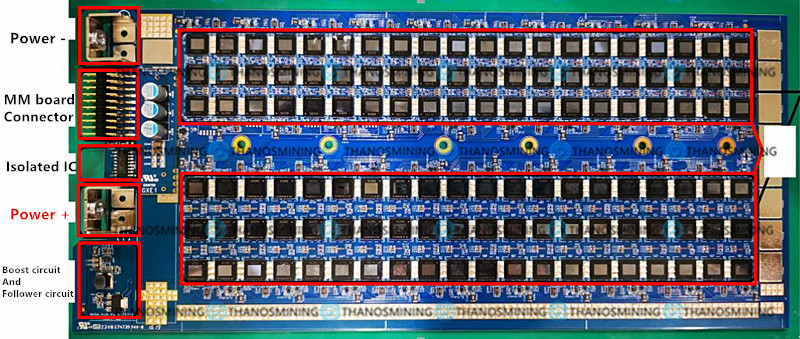
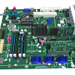
1. Positive and negative poles of the power supply;
2. Communication interface: communicate with MM board;
3. Main chip: ASIC chip;
4. Isolated chip unit;
5. Boost and follower circuit.

A10 series hash board test fixture interface introduction:
1. Connect the positive and negative poles of the Hash board power supply;
2. Connect the data cable of the hash board;
3. It is recommended to install the tooling bottom plate (insulation);
4. MM board with test script program;
5. Adjustable power interface cable;
6. USB to a serial port, connect the USB to the computer, and read the hash board test information through the serial port debugging tool.

Test fixture connection method:
1. The power supply interface of the primary circuit of the power supply, in which black is the main output negative pole, and red is the main output positive pole;
2. The negative interface of the main circuit power supply of the Hash board;
3. Hash board main circuit power supply positive interface;
4. The data protocol interface of the hash board;
5. USB to a serial port, the interface is defined as:
|
Test fixture |
USB to TTL |
|
TX |
TXD |
|
RX |
RXD |
|
GND |
GND |
6. Power supply 12VSB and IIC interface (2*4 interface).
Hash board test method:
①According to the status of the indicator light of the test fixture, to determine the status of the hash board, and to determine whether maintenance is required;
· A green light indicates that the hash board is healthy and does not require maintenance.
· The red light indicates that the hash board is abnormal and needs to be repaired.
②By connecting the serial port debugging tool to the computer screen, determine whether there is a problem with the hash board;
First, set the serial port software debugging parameters: among them, the baud rate is set to 115200, the data bit is 8, and the stop bit is 1.
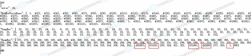
Through the serial port debugging tool, check the LOG information of the hash board running on the computer, as shown in the figure:

Among them, the ASIC count is 120 chips, and the test fixture is bright red, indicating that the test circuit is not working and needs to be repaired. In addition, the 9th item + 7 item + 6 item in the above figure = a total of 22 items, indicating that there are problems with these three indicators, which need to be checked and repaired.
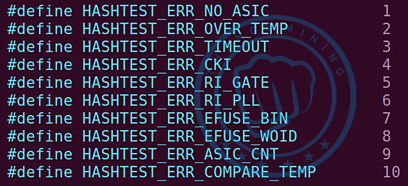
The following figure is the error code comparison table:

Error code description:
|
Error code |
Describe |
|
1 |
Failed to enumerate ASIC chips |
|
2 |
ASIC chip high temperature (greater than 90°C) |
|
3 |
Test timeout |
|
4 |
CKL signal error |
|
5 |
RI signal error in gate state |
|
6 |
RI signal error at the configured frequency |
|
7 |
ASIC chip BIN information error |
|
8 |
ASIC chip batch number error |
|
9 |
ASIC chip voltage error |
|
10 |
The difference between the maximum and minimum temperature of the ASIC chip is relatively large |
The software can scan the chip, but if the chip is not working, the voltage entry will show 0, and a comma will appear after each voltage value.
If the software does not scan the chip voltage value, the software will automatically fill in 0. It is necessary to check the adjacent chip at the 0 positions during maintenance. Likely, the 0 positions or the adjacent chip does not work.

Hash board voltage test:
The first thing to do is test the power supply’s impedance on the hash board. The resistance values are shown in the table below. If there is a short, you’ll need to inspect parts of the circuit for burnout or solder shorts. After the impedance test is completed, the power-on test is performed to test the power supply voltage of the entire hash board. The test positions and test voltage values are as follows:

The measured position and voltage values are:
|
Test power |
Test location |
Voltage value |
Impedance value |
|
Power voltage |
«-» is in black clip & Vcore+ |
11.15V |
2Ω |
|
Boost circuit voltage |
«-» is on the black clip and the left end of the C399 |
16.28V |
≥60kΩ |
|
Follow circuit voltage |
«-» is at the black clip and U98 pin4 |
12.95V |
≥400Ω |
ASIC chip detection:
If the voltage test passes, the ASIC chip of the hash board needs to be tested. Take the A10 hash board as an example; there are 40 groups of chips connected in series on the hash board, each group of chips is composed of 3 chips in parallel, and each chip includes three power supplies and 4 groups of signals: Vcore, VTOP and VDDIO, the signal is: CKin, Cin, Rin, Din and CKout, Cout, Rout, Dout.
Each group of chips consists of three chips in parallel. The VDDIO and VTOP of each group of chips are powered by 1.8V-LDO and 0.75V-LDO, respectively. In addition, there will be VDDIO and VTOP test points next to each group of chips, which can test the voltage value.
as follows:
|
Chip voltage test, the working voltage value of each chip is: |
|
|
Type |
Voltage value |
|
Vcore |
280mV |
|
VDDIO |
1.8V |
|
VTOP |
0.75V |
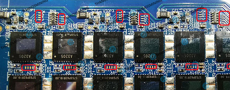
Signal test:
When there is a problem with the hash board, it is necessary to test the chip’s signal and power supply IO and TOP. This is because the chips’ signals on the hash board are connected in series, the signals of each chip are CK, C, R, and D, and each chip needs to test the output signal.

The enlarged hash board is shown in the figure below, where the red box is the test point of the ASIC chip:

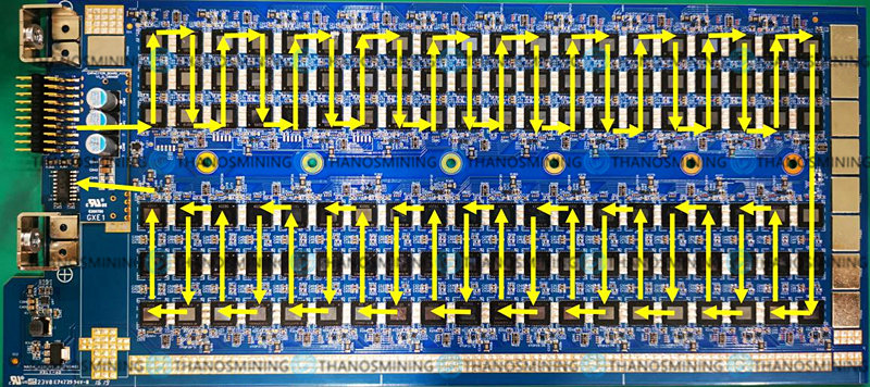
Description of the signal transmission direction of the Avalon hash board:
Each group of signals includes four signal test points, they are CK, D, R, and C;
CK: Chip working clock, the frequency is 25MHz;
D: The transmission data signal of the chip;
R: The reset pin of the chip;
C: The transmission clock signal of the chip.

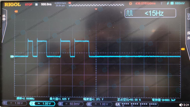
Test the waveform with an oscilloscope to determine whether the chip is abnormal:
The oscilloscope settings are AC position; amplitude is set to 1.00V/div; frequency is set to 500ns/div.
The waveform of the CK signal, the frequency is 25MHz, and the amplitude is 1.5V-1.8V;

The waveform of the C signal, the frequency is 5MHz, and the amplitude is 1.5V-1.8V;

The waveform of the D signal, the amplitude is 1.5V-1.8V

Please use a Fluke multimeter for chips with abnormal waveforms to test their voltage and resistance values. When it is determined that the ASIC chip is damaged, please replace the damaged ASIC chip by yourself.
NOTICE
This is an original piece. Reproduction in whole or part without written permission is prohibited.
19 тем в этом разделе форума
- Сортировка
-
-
1
ответ -
409
просмотров
-
1
-
W25Q64FW1 ava 1166pro-78 2101.BIN
Автор:misha_res55,
18 Декабря 2022-
0
ответов -
146
просмотров
-
0
-
-
1
ответ -
446
просмотров
-

-
Green17gobliN88
-
28 Ноября 2022
-
1
-
Log Description. Разбор логов
Автор:Pavel38,
30 Ноября 2021-
1
ответ -
614
просмотров
-
-
Serg Bitriver Tsyvkin
-
17 Ноября 2022
-
1
-
-
0
ответов -
414
просмотров
-
0
-
бп авалон 1066.дежурка
Автор:Pirat,
3 Августа 2022-
1
ответ -
338
просмотров
-
1
-
Описание лога Avalon rus
Автор:evgeniy,
21 Июня 2022-
0
ответов -
381
просмотр
-
0
-
-
0
ответов -
366
просмотров
-
0
-
-
0
ответов -
541
просмотр
-
0
-
User manual 1246
Автор:RedTapok,
5 Мая 2022-
0
ответов -
468
просмотров
-
0
-
-
3
ответа -
900
просмотров
-
3
-
-
0
ответов -
673
просмотра
-
0
-
-
0
ответов -
2,1k
просмотра
-
0
-
-
3
ответа -
674
просмотра
-
3
-
Описание лога Avalon
Автор:666Rakot,
2 Февраля 2022-
0
ответов -
631
просмотр
-
0
-
-
0
ответов -
750
просмотров
-
0
-
Поднятие хэшрейта 1066
Автор:Stickler25,
21 Января 2022-
0
ответов -
6,9k
просмотров
-
0
-
-
0
ответов -
751
просмотр
-
0
-
-
0
ответов -
546
просмотров
-
0


It mainly explains how to repair hash board of Canaan Avalon A10 series, suitable for AvalonMiner A1066, A1066pro, A1026, A1046, A1047 and other models.
A10 series hash board introduction:
1. The positive pole of the power supply and the negative pole of the power supply: connect the positive pole and the negative pole of the power supply;
2. JamLink communication: communicate with MM;
3. Main chip: ASIC chip.
4. Isolated chip unit
5. Boost and follower circuit
A10 series hash board test fixture introduction (official test fixture):
1. Connect the positive and negative poles of the power supply of the hash board;
2. Connect the JamLink data cable of the hash board;
3. It is recommended to install the tooling bottom plate (insulation);
4. MM board with test script program;
5. Kosebao adjustable power interface cable;
6. Connect the USB to serial port, connect the USB to the computer, and the hash board test information can be read out through the serial port debugging tool.

Test fixture connection method:
1. The main circuit power interface of Gaussian power supply, in which black is the main output negative pole, and red is the main output positive pole;
2. Negative interface of the main circuit power supply of the hash board;
3. The positive interface of the main circuit power supply of the hash board;
4. JamLink data protocol interface of hash board;
5. USB to serial port, the interface is defined as:
| Test Fixture | USB to TTL |
| TX | TXD |
| RX | RXD |
| GND | GND |
6. Gospo power supply 12VSB and IIC interface (2×4 interface).
————————————————————
Testing method:
①
Judge the status of the hash board, judge the status of the hash board according to the status of the indicator light of the test fixture, and judge whether it needs repair.
A green light indicates that the hash board is healthy and does not require repair.
A red light indicates that the hash board is abnormal and needs to be repaired.
②
Connect the computer screen through the serial port to determine whether there is a problem with the Hash board, first set the serial port software debugging parameters:
The serial port debugging tool needs to set the serial port number, and the baud rate is set to 115200, the data bit is 8, and the stop bit is 1.
Through the serial port debugging tool, check the LOG information of the hash board running on the computer, as shown in the figure:

Among them, the number of asic counts is 120 chip, and the test fixture is on red, indicating that the test loop is not working and needs to be repaired. The 9th item in the above figure + 7 items + 6 items = total item 22, indicating that there are problems with these three indicators , need to be checked and repaired one by one.
The following figure is the error code comparison table:
Error code explanation:
| Error code | Describe |
| 1 | Failed to enumerate ASIC chip |
| 2 | High temperature of ASIC chip (greater than 90°C) |
| 3 | Test timeout |
| 4 | CKL signal error |
| 5 | RI signal error in gate state |
| 6 | RI signal error at configured frequency |
| 7 | ASIC chip BIN information error |
| 8 | ASIC chip batch number error |
| 9 | ASIC chip voltage error |
| 10 | The difference between the maximum and minimum temperature of the ASIC chip is relatively large |
The software can scan the chip, but the chip does not work, the voltage item will display 0, and a comma will appear after each voltage value.
If the chip voltage value is not scanned, the software will automatically fill in 0. At this time, it will be automatically divided into 3 strings, and a comma will be automatically added after each 3 values. When repairing, it is necessary to check the adjacent chip at the 0 position, jiyou may be 0 position or the adjacent chip is not working.
Hash board voltage test:
First of all, it is necessary to test the impedance of the power supply on the Hash board. The resistance values are shown in the following table. If there is a short circuit, you need to check the part of the circuit to see if there is any burnout or welding short circuit. After the impedance test is completed, the power-on test is performed to test the power supply voltage of the entire Hash board. The test position and test voltage value are as follows:

The measured position and voltage values are:
| Test power | Test location | Voltage value | Impedance value |
| Mains supply voltage | «-» at the black clip&Vcore+ | 11.15V | 2Ω |
| Boost circuit voltage | «-» at the black clip & the left end of C399 | 16.28V | ≥60kΩ |
| Follow circuit voltage | «-» at the black clip & U98 pin4 | 12.95V | ≥400Ω |
————————————————————
ASIC chip detection:
If the voltage test passes, you need to test the ASIC chip of the hash board. Take A10 as an example, there are 40 groups of chips connected in series on the Hash board, each group of chips is composed of 3 chips in parallel, each chip includes three power supplies and 4 groups of signals: Vcore, VTOP and VDDIO, the signals are: CKin, Cin, Rin, Din and CKout, Cout, Rout, Dout.
Each group of chips is composed of three chips in parallel. The VDDIO and VTOP of each group of chips are powered by 1.8V-LDO and 0.75V-LDO respectively. There will be VDDIO and VTOP test points next to each group of chips, which can be tested Voltage value.
As follows:
| Chip voltage test, the working voltage value of each chip is: | |
| Type | Voltage value |
| Vcore | 280mV |
| VDDIO | 1.8V |
| VTOP | 0.75V |
————————————————————
Signal test:
When there is a problem with the hash board, it is necessary to test the signals of the chips on the hash board and the power supply of IO and TOP. The signals of the chips on the hash board are connected in series, and the signals of each chip are CK, C, R, D, Each chip needs to be tested for output signals.

The enlarged picture, the red box is the test point of the ASIC chip:
————————————————————
Signal transmission direction of Avalon Hash board:
Each group of signals includes four signals: CK, D, R, and C:
CK: the working clock of the chip, the frequency is 25MHz;
D: The transmission data signal of the chip;
R: the reset pin of the chip;
C: The transmission clock signal of the chip.
———————————————————
Test the waveform with an oscilloscope to determine whether the chip is abnormal
The oscilloscope settings are:
AC position;
The amplitude is set to 1.00V/div;
The frequency is set to 500ns/div.
The waveform of the CK signal, the frequency is 25MHz, the amplitude is 1.5V-1.8V

C waveform, frequency 5MHz, amplitude 1.5V-1.8V

D waveform, the amplitude is 1.5V-1.8V
For the chip with abnormal waveform, please use a multimeter to test its voltage and resistance value. When it is determined that the ASIC chip is damaged, please replace the ASIC chip by yourself.

Your email address will not be published.Required fields are marked. *
Avalon A10 Series Hash Board Repair Guide
This hash board repair guide is suitable for Avalon Miner A1066, A1066pro, A1026, A1046, A1047, etc.
1. Positive and negative poles of the power supply;
2. Communication interface: communicate with MM board;
3. Main chip: ASIC chip;
4. Isolated chip unit;
5. Boost and follower circuit.
1. Connect the positive and negative poles of the Hash board power supply;
2. Connect the data cable of the hash board;
3. It is recommended to install the tooling bottom plate (insulation);
4. MM board with test script program;
5. Adjustable power interface cable;
6. USB to a serial port, connect the USB to the computer, and read the hash board test information through the serial port debugging tool.
Test fixture connection method:
1. The power supply interface of the primary circuit of the power supply, in which black is the main output negative pole, and red is the main output positive pole;
2. The negative interface of the main circuit power supply of the Hash board;
3. Hash board main circuit power supply positive interface;
4. The data protocol interface of the hash board;
5. USB to a serial port, the interface is defined as:
6. Power supply 12VSB and IIC interface (2*4 interface).
Hash board test method:
①According to the status of the indicator light of the test fixture, to determine the status of the hash board, and to determine whether maintenance is required;
· A green light indicates that the hash board is healthy and does not require maintenance.
· The red light indicates that the hash board is abnormal and needs to be repaired.
②By connecting the serial port debugging tool to the computer screen, determine whether there is a problem with the hash board;
First, set the serial port software debugging parameters: among them, the baud rate is set to 115200, the data bit is 8, and the stop bit is 1.
Through the serial port debugging tool, check the LOG information of the hash board running on the computer, as shown in the figure:
Among them, the ASIC count is 120 chips, and the test fixture is bright red, indicating that the test circuit is not working and needs to be repaired. In addition, the 9th item + 7 item + 6 item in the above figure = a total of 22 items, indicating that there are problems with these three indicators, which need to be checked and repaired.
Если вы хотите разместить ФАЙЛ инструкции, прошивки или любого другого (кроме фото) то вам необходимо воспользоваться разделом ФАЙЛЫ , выбрать там раздел, после загрузки, на форуме, будет создана тема по этому файлу автоматически от вашего имени.
Если вы хотите разместить любое фото (схемы, оборудования и т.д), то для этого нужно создать тему или сообщение в уже созданной теме.
19 тем в этом разделе форума
- Сортировка
- Вручную
W25Q64FW1 ava 1166pro-78 2101.BIN
- 0 ответов
- 58 просмотров
- misha_res55
- 18 Декабря 2022
Дамп китай разбери ZG 834 v1.3 vs v1.2
- 1 ответ
- 382 просмотра
- Green17gobliN88
- 28 Ноября 2022
Log Description. Разбор логов
- 1 ответ
- 570 просмотров
- Serg Bitriver Tsyvkin
- 17 Ноября 2022
Руководство по ремонту платы Avalon A1066/A1026/A1046/A1047
- 0 ответов
- 313 просмотров
- Artoym_Belov
- 1 Сентября 2022
бп авалон 1066.дежурка
- 1 ответ
- 242 просмотра
- Makaveli
- 3 Августа 2022
Описание лога Avalon rus
- 0 ответов
- 300 просмотров
- evgeniy
- 21 Июня 2022
Avalon Hash Board Repair Manual 82 84 85 Series
- инструкция
- manual
- (и еще 4 )
- инструкция
- manual
- avalon
- avalon 82
- avalon 84
- avalon 85
- 0 ответов
- 315 просмотров
- Kowex
- 26 Мая 2022
инструкция Avalon A1066/A1026/A1046/A1047 Hash Board Repair Manual
- manual
- avalon
- (и еще 4 )
- manual
- avalon
- avalon a1066
- avalon a1026
- avalon a1046
- avalon a1047
- 0 ответов
- 486 просмотров
- Kowex
- 26 Мая 2022
Avalon A1066/A1026/A1046/A1047 Hash Board Repair Manual
- 0 ответов
- 314 просмотров
- k6demos
- 26 Мая 2022
User manual 1246
- 0 ответов
- 401 просмотр
- RedTapok
- 5 Мая 2022
Canaan Service Center Training Manual手册10-29—翻页版预览
- 3 ответа
- 853 просмотра
- Sasha
- 23 Апреля 2022

Инструкция по ремонту Avalon 721, 741, 761, 821, 841
- инструкция
- manual
- (и еще 6 )
- инструкция
- manual
- avalon
- avalon 721
- avalon 741
- avalon 761
- avalon 821
- avalon 841
- 0 ответов
- 618 просмотров
- Kowex
- 17 Марта 2022
AvalonMinerViewer
- 0 ответов
- 1,9k просмотров
- bot
- 15 Марта 2022

Ремонт блока питания
- ремонт avalona
- avalon
- (и еще 9 )
- ремонт avalona
- avalon
- avalon941
- avalon 911
- avalon 920
- avalon 921
- avalon 1026
- avalon 1126
- avalon 1226
- схема блока питания avalon
- инструкция по ремонту блока питания avalon
- 3 ответа
- 582 просмотра
- valerich
- 27 Февраля 2022
Описание лога Avalon
- 0 ответов
- 573 просмотра
- 666Rakot
- 2 Февраля 2022
.thumb.jpg.9d3a9947cbb68af1002f7670a372a746.jpg)
инструкция Инструкция по ремонту Canaan Service Center Training Manual 10-29
- manual
- canaan
- (и еще 1 )
- manual
- canaan
- avalon
- 0 ответов
- 696 просмотров
- bot
- 30 Января 2022
Поднятие хэшрейта 1066
- 0 ответов
- 6,1k просмотр
- Stickler25
- 21 Января 2022
Avalon A1066/A1026/A1046/A1047 Hash Board Repair Manual
It mainly explains how to repair hash board of Canaan Avalon A10 series, suitable for AvalonMiner A1066, A1066pro, A1026, A1046, A1047 and other models.
A10 series hash board introduction:
1. The positive pole of the power supply and the negative pole of the power supply: connect the positive pole and the negative pole of the power supply;
2. JamLink communication: communicate with MM;
3. Main chip: ASIC chip.
4. Isolated chip unit
5. Boost and follower circuit
A10 series hash board test fixture introduction (official test fixture):
1. Connect the positive and negative poles of the power supply of the hash board;
2. Connect the JamLink data cable of the hash board;
3. It is recommended to install the tooling bottom plate (insulation);
4. MM board with test script program;
5. Kosebao adjustable power interface cable;
6. Connect the USB to serial port, connect the USB to the computer, and the hash board test information can be read out through the serial port debugging tool.
Test fixture connection method:
1. The main circuit power interface of Gaussian power supply, in which black is the main output negative pole, and red is the main output positive pole;
2. Negative interface of the main circuit power supply of the hash board;
3. The positive interface of the main circuit power supply of the hash board;
4. JamLink data protocol interface of hash board;
5. USB to serial port, the interface is defined as:
| Test Fixture | USB to TTL |
| TX | TXD |
| RX | RXD |
| GND | GND |
6. Gospo power supply 12VSB and IIC interface (2×4 interface).
Testing method:
①
Judge the status of the hash board, judge the status of the hash board according to the status of the indicator light of the test fixture, and judge whether it needs repair.
A green light indicates that the hash board is healthy and does not require repair.
A red light indicates that the hash board is abnormal and needs to be repaired.
②
Connect the computer screen through the serial port to determine whether there is a problem with the Hash board, first set the serial port software debugging parameters:
The serial port debugging tool needs to set the serial port number, and the baud rate is set to 115200, the data bit is 8, and the stop bit is 1.
Through the serial port debugging tool, check the LOG information of the hash board running on the computer, as shown in the figure:
Among them, the number of asic counts is 120 chip, and the test fixture is on red, indicating that the test loop is not working and needs to be repaired. The 9th item in the above figure + 7 items + 6 items = total item 22, indicating that there are problems with these three indicators , need to be checked and repaired one by one.
The following figure is the error code comparison table:
Error code explanation:
| Error code | Describe |
| 1 | Failed to enumerate ASIC chip |
| 2 | High temperature of ASIC chip (greater than 90°C) |
| 3 | Test timeout |
| 4 | CKL signal error |
| 5 | RI signal error in gate state |
| 6 | RI signal error at configured frequency |
| 7 | ASIC chip BIN information error |
| 8 | ASIC chip batch number error |
| 9 | ASIC chip voltage error |
| 10 | The difference between the maximum and minimum temperature of the ASIC chip is relatively large |
The software can scan the chip, but the chip does not work, the voltage item will display 0, and a comma will appear after each voltage value.
If the chip voltage value is not scanned, the software will automatically fill in 0. At this time, it will be automatically divided into 3 strings, and a comma will be automatically added after each 3 values. When repairing, it is necessary to check the adjacent chip at the 0 position, jiyou may be 0 position or the adjacent chip is not working.
Hash board voltage test:
First of all, it is necessary to test the impedance of the power supply on the Hash board. The resistance values are shown in the following table. If there is a short circuit, you need to check the part of the circuit to see if there is any burnout or welding short circuit. After the impedance test is completed, the power-on test is performed to test the power supply voltage of the entire Hash board. The test position and test voltage value are as follows:
The measured position and voltage values are:
| Test power | Test location | Voltage value | Impedance value |
| Mains supply voltage | «-» at the black clip&Vcore+ | 11.15V | 2Ω |
| Boost circuit voltage | «-» at the black clip & the left end of C399 | 16.28V | ≥60kΩ |
| Follow circuit voltage | «-» at the black clip & U98 pin4 | 12.95V | ≥400Ω |
ASIC chip detection:
If the voltage test passes, you need to test the ASIC chip of the hash board. Take A10 as an example, there are 40 groups of chips connected in series on the Hash board, each group of chips is composed of 3 chips in parallel, each chip includes three power supplies and 4 groups of signals: Vcore, VTOP and VDDIO, the signals are: CKin, Cin, Rin, Din and CKout, Cout, Rout, Dout.
Each group of chips is composed of three chips in parallel. The VDDIO and VTOP of each group of chips are powered by 1.8V-LDO and 0.75V-LDO respectively. There will be VDDIO and VTOP test points next to each group of chips, which can be tested Voltage value.
As follows:
| Chip voltage test, the working voltage value of each chip is: | |
| Type | Voltage value |
| Vcore | 280mV |
| VDDIO | 1.8V |
| VTOP | 0.75V |
Signal test:
When there is a problem with the hash board, it is necessary to test the signals of the chips on the hash board and the power supply of IO and TOP. The signals of the chips on the hash board are connected in series, and the signals of each chip are CK, C, R, D, Each chip needs to be tested for output signals.
The enlarged picture, the red box is the test point of the ASIC chip:
Signal transmission direction of Avalon Hash board:
Each group of signals includes four signals: CK, D, R, and C:
CK: the working clock of the chip, the frequency is 25MHz;
D: The transmission data signal of the chip;
R: the reset pin of the chip;
C: The transmission clock signal of the chip.
Test the waveform with an oscilloscope to determine whether the chip is abnormal
The oscilloscope settings are:
AC position;
The amplitude is set to 1.00V/div;
The frequency is set to 500ns/div.
The waveform of the CK signal, the frequency is 25MHz, the amplitude is 1.5V-1.8V
C waveform, frequency 5MHz, amplitude 1.5V-1.8V
D waveform, the amplitude is 1.5V-1.8V
For the chip with abnormal waveform, please use a multimeter to test its voltage and resistance value. When it is determined that the ASIC chip is damaged, please replace the ASIC chip by yourself.
Avalon 1166
ASIC miner manufacturer Canaan did not break the tradition of the 11-series lineup, laid down by the marking of the 10-series. After the summer release of 1126 in 2020, miners received Avalon with the index 1166 already in October.
The ASIC miner was produced on a 16nm chip, which had been used up to that point in the 10 and 11 series. The chip showed high reliability in operation, which allowed Canaan to «squeeze» higher hash rate parameters out of it by working on the cooling circuit and power supply unit.
As a result, the Avalon 1166 produced output parameters:
- Working Algorithm: SHA-256
- Cooling system: Air cooled by 4x fans
- Chip process size: 16nm
- Hash rate: 68 TH/s
- Power Consumption: 3196W
- Energy efficiency: 47 J/TH
- Operating temperature range: 5-35C
- Noise level: 75 dB
- Weight: 12.8 kg
- Dimensions: 331 x 195 x 292
Despite the Avalon 1166 model being equipped with a 16nm chip, it continues to work on farms. The owners of the equipment with the help of installation of custom and stock firmware achieve an increase in the profitability of mining.
The actual software for ASIC-miners updates is available in the special section of our website. The custom or stock firmware of older models reduces the entry threshold into mining, gives compromise solutions for farm upgrades.
Avalon 1166 PRO S 72T
Canaan has decided in 2021 to return to the 11-series, despite the launch of newer, 12-series devices. Probably, the ASIC miner manufacturer went for such a deed because of the lack of the latest chips. Model Avalon 1166 PRO with the index S reliable 16 nm processor, but a significantly improved cooling system, as well as a powerful power supply.
In this build, the 1166 PRO S 72 produced the following specifications:
- Operating Algorithm: SHA-256
- Cooling system: 4 fans air cooling
- Chip process size: 16nm
- Hash rate: 72 TH/s
- Power Consumption: 3420W
- Energy efficiency: 48 J/TH
- Operating temperature range: 5-35C
- Noise level: 75 dB
- Weight: 11.2 kg
- Dimensions: 331 x 195 x 292
In the process of operating the equipment there appeared custom and stock firmware, after the update increasing the cryptocurrency mining performance. Current versions of these programs can be found in a special section of our website.
Avalon 1166 PRO S 75T
ASIC-miner Avalon 1166 PRO S 75T was released simultaneously with the other models of the updated line with the index «S». This miner turned out to be the most productive device, closing out the 11 series and platforms with a 16nm chip.
Canaan provided the following specifications for the Avalon 1166 PRO S 75T:
- Operating Algorithm: SHA-256.
- Cooling system: 4 fans air cooling system
- Chip process size: 16nm
- Hash rate: 75 TH/s
- Power Consumption: 3420W
- Energy efficiency: 46 J/TH
- Operating temperature range: 5-35C
- Noise level: 75 dB
- Weight: 11.2 kg
- Dimensions: 331x95x292
The use of custom and stock firmware will allow the owners of the equipment to stop the choice of older models, significantly reducing the investment in the mining farm.
Crazy Mining LLC delivers mining equipment, ASIC miners, video cards, power supplies — to any country in the Northern Hemisphere, we also provide bulk uninterrupted supplies from China.
Руководство по ремонту Troubleshooting and repair guide for AvalonMiner models 721, 741, 761, 821 and 841
Руководство по ремонту майнеров
—————-
Предназначено для работы в следующих моделях :
Деталь может быть как новая, так и восстановленная, уточняйте запросом на почту.
Гарантия при установке в сервисном центре партнера Vce-O-Printere неделя. Все имена и торговые марки являются собственностью их владельцев и используются только с целью описания продукта.
Вся информация на сайте носит справочный характер и не является публичной офертой, определяемой положениями Статьи 437 Гражданского кодекса Российской Федерации.
Информация о товарах, их характеристиках, упаковке, внешнем виде и комплектации, а также ценах, может как содержать ошибки, так и быть изменена производителем без предварительного уведомления.
Клиент вправе вернуть товар в течение 14 дней с момента его получения. Товар без механических повреждений и следов использования (В соответствии со статьей 502 Гражданского кодекса Российской Федерации). Возврат товара осуществляется за счет клиента.
Запросы по обмену или возврату товара будут приниматься к рассмотрению, если товар ни при каких условиях не был в эксплуатации и не устанавливался. При обнаружении на запчасти явных следов эксплуатации, попытки установки или разного рода повреждений – товар обмену или возврату не подлежит.
Зарегистрируйтесь, чтобы создать отзыв.
Copyright MAXXmarketing Webdesigner GmbH