- Manuals
- Brands
- CUMMINS Manuals
- Engine
- 6BT5.9
Manuals and User Guides for CUMMINS 6BT5.9. We have 2 CUMMINS 6BT5.9 manuals available for free PDF download: Shop Manual, Service Manual
CUMMINS 6BT5.9 Shop Manual (462 pages)
Brand: CUMMINS
|
Category: Engine
|
Size: 15.03 MB
Table of Contents
-
Foreword
2
-
Table of Contents
3
-
Cummins 22-Group System Exploded Diagram
4
-
How to Use the Manual
5
-
Generic Symbols
6
-
Introduction
8
-
Section Contents
8
-
About the Manual
9
-
General Safety Instructions
10
-
General Repair Instructions
11
-
General Cleaning Instructions
12
-
Glossary of Terms
13
-
Engine and Component Identification
15
-
Engine Identification
16
-
Industrial Engine Nomenclature
17
-
Automotive Engine Nomenclature
17
-
Injection Pump Dataplate
18
-
General Engine Specifications
20
-
Engine Diagram-Automotive Engine
23
-
Inlet Side
23
-
Rear View
23
-
Turbocharger Side View
24
-
Front View
24
-
Engine Disassembly and Assembly
25
-
Engine Disassembly and Assembly-Service Tools
29
-
Engine Disassembly Check List
31
-
Engine Disassembly
32
-
Steam Cleaning the Engine
32
-
Engine Weight
32
-
Rollover Stand-Engine Mounting
32
-
Oil-Draining
33
-
Lifting Bracket Removal-Rear
33
-
Drive Beit-Removal
33
-
Fan Pulley-Removal
34
-
Vibration Damper/Crankshaft Pulley-Removal
34
-
Belt Tensioner-Removal
34
-
Fan Hub-Removal
35
-
Alternator-Removal
35
-
Thermostat-Removal
36
-
Turbocharger-Removal
36
-
Exhaust Manifold-Removal
38
-
Fuel Filter-Removal
38
-
Fuel Filter Head-Removal
39
-
KSB (Remote Mounted)-Removal
39
-
Fuel Lines-Removal
40
-
High Pressure Fuel Line-Removal
40
-
Fuel Drain Manifold-Removal
41
-
Low Pressure Fuel Lines-Removal
42
-
Dipstick-Removal
43
-
Manifold Cover-Removal
43
-
Aftercooler-Removal
43
-
Valve Covers-Removal
44
-
Injector Nozzles-Removal
44
-
Rocker Levers-Removal
45
-
Push Rods-Removal
45
-
Cylinder Head-Removal
46
-
Front Cover-Removal
46
-
Water Pump-Removal
47
-
Flywheel-Removal
47
-
Flywheel Housing-Removal
47
-
Accessories-Removal
48
-
Injection Pump-Removal (Rotary Type Pumps)
48
-
Gear Lash-Check
48
-
Locking the Pump
49
-
Drive Gear-Removal
50
-
Injection Pump-Removal (In-Line)
50
-
Fuel Transfer Pump-Removal
52
-
Tappet Cover-Removal
52
-
Side Oil Fill-Removal
53
-
Oil Cooler-Removal
53
-
Water Inlet Connection-Removal
53
-
Oil Pan-Removal
54
-
Suction Tube-Removal
54
-
Rear Seal Housing-Removal
54
-
Camshaft-Removal
55
-
Measuring Gear Lash
55
-
Valve Tappets-Removal
56
-
Lube Pump-Removal
56
-
Measuring Backlash
56
-
Timing Pin Housing-Removal
58
-
Gear Housing-Removal
58
-
Balancer-Removal
59
-
Measuring the End Play
59
-
Locking the Balancer
59
-
Removing the Balancer
60
-
Piston and Rod Assemblies-Removal
61
-
Crankshaft-Removal
63
-
Turbocharger Drain Tube-Removal
65
-
Cylinder Block-Removing from the Rollover Stand
65
-
Engine Assembly
65
-
Cylinder Block-Prepare for Assembly
65
-
Valve Tappets-Installation
66
-
Crankshaft-Installation
66
-
Piston and Rod Assemblies-Installation
71
-
Piston Grading for 1994 Automotive Applications Only
71
-
Dial Indicator
72
-
Piston Protrusion
74
-
Piston and Connecting Rod Assemblies-Installation
74
-
Gear Housing-Installation
78
-
Lube Pump-Installation
79
-
Camshaft-Installation
80
-
Camshaft End Play-Measuring
82
-
Camshaft Gear Backlash-Measuring
83
-
Timing Pin-Installation
83
-
Crankshaft End Play-Measuring
90
-
Rear Seal-Installation
90
-
Suction Tube-Installation
91
-
Oil Pan-Installation
92
-
Oil Pan Sealing Surfaces-Sealants
92
-
Oil Cooler-Installation
93
-
Side Oil Fill-Installation
93
-
Fuel Transfer Pump-Installation
93
-
Tappet Cover-Installation
94
-
Injection Pump-Installation
95
-
Locked Timed Injection Pump-Installation
96
-
Injection Pumps-Unlocking
98
-
Chisel, Hammer
99
-
Unlocked CAV Injection Pump-Installation
100
-
Unlocked Stanadyne DB4 Injection Pump-Installation
101
-
Unlocked Bosch VE and P7100 Injection Pump-Installation
104
-
Disengage the TDC Pin
107
-
Pump Gear Backlash Limit
107
-
Injection Pump Installation
108
-
Accessories-Installation
112
-
Flywheel Housing-Installation
113
-
Flywheel-Installation
113
-
Water Pump-Installation
114
-
Front Cover-Installation
115
-
Cylinder Head-Installation
116
-
Push Rods-Installation
117
-
Rocker Levers-Installation
118
-
Cylinder Head-Tightening
119
-
Valve Clearance-Adjustment
121
-
Valve Stem to Rocker Lever Clearance
122
-
Injector Nozzles-Installation
123
-
Valve Covers-Installation
124
-
Manifold Cover-Installation
124
-
Aftercooler-Installation
125
-
Fuel Lines-Installation
125
-
Infection Pump Supply Line-Installation
125
-
Fuel Drain Manifold-Installation
126
-
Injection Pump Vent Line-Installation
126
-
High Pressure Fuel Lines-Installation
127
-
KSB (Remote Mounted)-Installation
128
-
Fuel Filter Head-Installation
128
-
Exhaust Manifold-Installation
129
-
Turbocharger-Installation
130
-
Thermostat-Installation
133
-
Vibration Damper-Installation
134
-
Fan Hub-Installation
134
-
Beit Tensioner-Installation
135
-
Water Inlet Connection-Installation
135
-
Alternator-Installation
135
-
Drive Belt-Installation
137
-
Oil Filter-Installation
137
-
Rollover Stand-Engine Removal
137
-
Starter-Installation
138
-
Cylinder Block
139
-
Cylinder Block-Exploded View
141
-
Cylinder Block-General Information
144
-
Cylinder Block-Service Tools
145
-
Cylinder Block Group Inspection Checklist
146
-
Cylinder Block-Precheck before Disassembly
147
-
Cylinder Block-Disassembly
147
-
Cylinder Block-Cleaning
149
-
Cylinder Block-Inspection
152
-
Cylinder Block-De-Glazing
154
-
Expansion and Pipe Plug-Installation
157
-
Camshaft Expansion Plug-Installation
159
-
Camshaft Bushing-Installation
160
-
Dipstick Tube-Replacement
162
-
Cylinder Block-Storing
162
-
Crankshaft-Cleaning
163
-
Crankshaft-Inspection
163
-
Crankshaft Gear-Replacement
164
-
Determining Mam Bearing Clearance
164
-
Camshaft-Cleaning
166
-
Camshaft and Gear-Inspection
166
-
Camshaft Lobe Pitting Reuse Criteria
167
-
Camshaft Lobe Edge Deterioration (Breakdown) Criteria
168
-
Camshaft Gear-Replacement
171
-
Camshaft Gear-Removal
171
-
Camshaft Gear-Installation (Heated Gear Method)
171
-
Camshaft Gear-Installation (with Special Tool 3823589)
173
-
Camshaft Capscrew-Installation
175
-
Rubber Element Vibration Damper-Cleaning and Inspection
176
-
Piston and Connecting Rod-Disassembly
178
-
Piston, Pin and Connecting Rod-Cleaning
178
-
Piston Inspection
179
-
Piston Pin-Inspection
180
-
Connecting Rod-Inspection
181
-
Rod Bearing Clearance-Checking
181
-
Piston and Connecting Rod-Assembly
182
-
Piston Ring Gap-Checking
183
-
Piston Rings-Installation
184
-
Balancer-Disassembly
185
-
Balancer-Assembly
188
-
Gear Housing and Timing Pin Assembly-Inspection
194
-
Gear Housing-Disassembly
195
-
Fuel Pump Stud-Replacement
195
-
Data Plate-Replacement
196
-
Cylinder Head
198
-
Cylinder Head-Service Tools
199
-
Cylinder Head Exploded View
200
-
General Information
202
-
Cylinder Head-Precheck before Disassembly
203
-
Cylinder Head-Disassembly
203
-
Cylinder Head-Cleaning
204
-
Valve-Inspection
206
-
Valve Guide Inspection
208
-
Cylinder Head Combustion Face Inspection
208
-
Valve Seat Inspection
208
-
Cylinder Head Cracks-Reuse Guidelines
209
-
Valve Spring Inspection
209
-
Cup Plug Replacement
210
-
Valves-Grinding
212
-
Valve Seats-Grinding
213
-
Calculating the Grinding Depth
213
-
Valve Depth
214
-
Seat Angle
214
-
Gauge Block
214
-
Seat Grinding Depth Limit
215
-
Valve Seat Width Limit
216
-
Cylinder Head-Assembly
218
-
Valve Spring Compressor
218
-
Rocker Levers
220
-
Rocker Lever Assembly-Exploded View
221
-
Rocker Lever Assembly-General Information
223
-
Rocker Levers-Disassembly
224
-
Rocker Levers and Pedestals-Cleaning
225
-
Rocker Lever-Inspection
225
-
Rocker Lever Pedestals-Inspection
226
-
Rocker Levers-Assembly
226
-
Tappets and Push Rods
228
-
Tappets and Push Rods-Exploded View
229
-
Tappets and Push Rods-General Information
230
-
Valve Tappets-Inspection
231
-
Push Rods-Inspection
231
-
Fuel System
233
-
Service Tools-Injection Pump
234
-
Exploded View-Fuel System
235
-
Injection Pump-General Information
236
-
Injection Pump-Identification
236
-
KSB Electrical Solenoid Style-General Information
238
-
Cold Start Timing Advance System (KSB)-Electrical Solenoid Style
238
-
VE Pump Timing Advance Principles (Without KSB)
239
-
VE Pump Timing Advance Principles (with Electrical Solenoid KSB Installed)
240
-
Warm Engine Operation (more than 90°F IMT), Retarded Timing
242
-
KSB Electrical Solenoid Style-Inspection
244
-
KSB Electrical Solenoid-Inspection
244
-
KSB Electrical Solenoid Style Wiring Harness-Inspection
246
-
Injection Pump Repairs-Bosch VE
247
-
Delivery Valve Holder/Sealing Washer-Replacement
248
-
Shutdown Solenoid-Replacement
249
-
Shutdown Lever/Spring-Replacement
250
-
Overflow Adapter/Sealing Ring-Replacement
251
-
Fuel Inlet Adapter/Seal-Replacement
252
-
Injection Pump Timing-Bosch VE
253
-
Injection Pump Repairs-Lucas CAV DPA
257
-
Back Leakage Valve-Replacement/Inspection
258
-
Bleed Screws/Sealing Washers-Replacement
260
-
Vent Fitting/Sealing Washer-Inspection/Replacement
261
-
Fuel Inlet Fitting/Sealing Washer-Replacement
262
-
Control Lever-Replacement
262
-
Inspect the Lever Components
263
-
Automatic Timing Advance-Disassembly
265
-
Timing Advance Components-Inspection
266
-
Timing Advance-Assembly
267
-
Injection Pump Repairs
271
-
Injection Pump Timing-Stanadyne DB4
271
-
Return Connection Replacement, Stanadyne DB4
272
-
Shutoff Solenoid Replacement, Stanadyne DB4
273
-
Speed Droop Adjustment off Engine-Stanadyne DB4
275
-
Injection Pump Timing-Nippondenso EP9
276
-
Seals Replacement, Nippondenso EP9
278
-
Shut down Lever or Spring Replacement, Nippondenso EP9
278
-
Pressure Relief Valve and Sealing Washer Replacement, Bosch P7100
280
-
Seal Replacement, Bosch P7100
282
-
Fuel Inlet Banjo Connector Replacement, Bosch P7100
282
-
Fuel Shut off Solenoid Replacement, Bosch P7100
283
-
Fuel Shut off Solenoid Adjustment, Bosch P7100
283
-
Fuel Shut off Solenoid Bracket Replacement, Bosch P7100
284
-
Fuel Pump Shut off Lever Replacement, Bosch P7100
284
-
Throttle Lever Replacement, Bosch P7100
285
-
Shutdown Solenoid Inspection, Bosch P7100
286
-
Wiring Guidelines
286
-
Solenoid Resistance Check
286
-
Solenoid Voltage Check
287
-
Injectors
288
-
Injector-Service Tools
289
-
Injector Group-Exploded View
290
-
General Information-Injectors
291
-
Fuel Transfer Pump-General Information
292
-
Fuel Transfer Pump-Identification
292
-
Injector-Disassembly
294
-
Injector-Clean and Inspect
295
-
Nozzle Cleaning Kit
296
-
Injector-Assembly
297
-
Injector-Testing
299
-
Chatter Test
300
-
Fuel Transfer Pump-Cleaning and Inspecting
300
-
Fuel Transfer Pump-Piston Style Rebuild
301
-
Cleaning
302
-
Assembly
302
-
Fuel Lines-Clean and Inspect
303
-
High Pressure Fuel Lines
303
-
Fuel Drain Manifold
304
-
Low Pressure Fuel Lines
305
-
Lubrication Oil System
307
-
Oil Pan and Suction Tube-Exploded View
308
-
Oil Pan and Suction Tube-General Information
309
-
Oil Pan and Suction Tube-Cleaning and Inspection
310
-
Lubricating Oil Cooler-Exploded View
311
-
General Information-Lubrication System
312
-
Pressure Regulator Valve-Disassembly
313
-
Pressure Regulator Valve-Inspection
313
-
Pressure Regulator Valve-Assembly
314
-
Filter Bypass Valve-Replace
314
-
Oil Cooler-Cleaning
315
-
Oil Cooler-Inspection
315
-
Lubricating Oil Pump-Exploded View
317
-
Lubrication Oil Pump-General Information
318
-
Oil Pump-Inspection
319
-
Cooling System
322
-
Water Pump-Exploded View
323
-
Water Pump-General Information
324
-
Water Pump-Inspection
325
-
Belt Tensioner and Fan Hub-Exploded View
326
-
Belt Tensioner and Fan Hub-General Information
327
-
Fan Hub-Inspection
328
-
Fan Hub-Disassembly
328
-
Fan Hub Assembly
329
-
Belt Tensioner-Inspection
331
-
Thermostat Housing Assembly-Exploded View
332
-
Thermostat Housing Assembly-General Information
333
-
Thermostat-Inspection
334
-
General Information about Fans
335
-
Drive Units
336
-
Accessory Drive Adapter-Exploded View
337
-
Drive Units-General Information
338
-
Accessory Drive-Cleaning
339
-
Accessory Drive-Inspection
339
-
Accessory Drive Adaptor-Disassembly
339
-
Accessory Drive Adaptor-Assembly
340
-
Air Intake System
342
-
Air Intake System-Exploded View
343
-
Air Intake System-General Information
345
-
Turbocharger-Cleaning and Inspection for Reuse
346
-
Inspection
346
-
Aftercooler Assembly-Cleaning and Inspection for Reuse
347
-
Pressure Test the Aftercooler Core
348
-
Aftercooler Assembly-Rebuild
348
-
Air Transfer Pipe-Cleaning and Inspection for Reuse
348
-
Air Crossover Tube-Cleaning and Inspection for Reuse
349
-
Charge Air Cooler (CAC)-Cleaning and Inspection for Reuse
349
-
Charge Air Cooler (CAC)-Pressure Testing
350
-
Exhaust System
352
-
Exhaust Manifold-Exploded View
353
-
Exhaust Manifold Inspection
355
-
Turbocharger Mounting Stud Replacement
355
-
Air Equipment
356
-
Air Equipment-General Information
357
-
Air Compressor-Cleaning and Inspection for Reuse
358
-
Power Steering Coupling (if Applicable)
358
-
Power Steering Adapter
359
-
Electrical Equipment
360
-
Electrical Equipment-General Information
361
-
Alternator Inspection
362
-
Starter Inspection
362
-
Engine Testing
363
-
Engine Testing-Service Tools
364
-
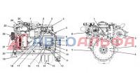
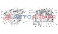
Engine Testing-Engine Side Views
366
-
Engine Testing-General Information
368
-
Blowby Measurement
369
-
Engine Dynamometer Test-Installation of the Engine
370
-
Engine Dynamometer Test-Engine Run-In
376
-
Engine Dynamometer Test-Performance Checking
380
-
Chassis Dynamometer-Operation
382
-
General Engine Test Procedures-(Chassis Dynamometer)
384
-
Engine Run-In Procedure-(Chassis Dynamometer)
387
-
Engine Run-In Procedure “In Chassis”-(On-And Off-Highway Vehicles)
389
-
Engine-Painting
390
-
Engine Storage-Short Term
391
-
Removing the Engine from Short-Term Storage
393
-
Engine Storage-Long Term
393
-
Removing the Engine from Long-Term Storage
396
-
Mounting Adaptations
400
-
Flywheel Housing
401
-
Flywheel and Ring Gear
401
-
Front Support
401
-
Flywheel and Ring Gear Inspection
402
-
Ring Gear Replacement
402
-
Flywheel Housing Inspection
403
-
Flywheel Housing Assembly
403
-
Wet Clutch Application
404
-
Front Support-Cleaning and Inspection
405
-
Engine Component Specifications
406
-
Specifications-General Information
407
-
Engine Component Torque Values
408
-
Component Specifications and Torque Values
411
-
Engine Assembly-Specifications
411
-
Engine Assembly-Capscrew Torque Values
415
-
Cylinder Block-Rebuild Specifications
421
-
Cylinder Block-Torque Values
427
-
Cylinder Head-Rebuild Specifications
428
-
Cylinder Head-Torque Values
430
-
Tappet and Push Rods
431
-
Lubricating Oil System-Specifications
434
-
Fan Hub-Specifications
436
-
Thermostat, Coolant Operating Temperature
436
-
Combustion Air System
436
-
Compressed Air System Torque Values
438
-
Electrical System
439
-
Engine Testing-Test Specifications
440
-
Drive Belt Tension
441
-
Weight and Measures-Conversion Factors
443
-
Newton-Meter to Foot-Pound Conversion Chart
444
-
Capscrew Markings and Torque Values-U.S. Customary
445
-
Capscrew Markings and Torque Values
446
-
Pipe Plug Torque Values
447
-
Tap-Drill Chart-U.S. Customary & Metric
448
-
Service Literature
449
-
Additional Service Literature
450
-
Service Literature Ordering Location
451
-
Service Literature Order Form
452
-
Component Manufacturers
454
-
United States and United Kingdom Offices
455
-
Index
458
-
Cummins Customized Parts Catalog
461
Advertisement
CUMMINS
DGBA
Service Manual
CUMMINS 6BT5.9 Service Manual (108 pages)
Detector Controls
Brand: CUMMINS
|
Category: Inverter
|
Size: 4.04 MB
Table of Contents
-
Table of Contents
3
-
Important Safety Instructions
5
-
Safety Precautions
7
-
Introduction
7
-
Ac Control
9
-
General
9
-
Standard Control Panel Components
9
-
Optional Control Panel Components
9
-
Automatic Voltage Regulator (AVR) Adjustments
10
-
Principle of Generator Operation
15
-
-
Engine Control
17
-
Control Panel
17
-
Standard Control Panel Components
17
-
Optional Control Panel Components
18
-
Control Box Interior
20
-
Engine Control Monitor (A11)
20
-
Engine Sensors
22
-
Auxiliary Control Components
26
-
Sequence of Operation
32
-
-
Troubleshooting
33
-
The Engine Does Not Crank
34
-
The Engine Cranks but Does Not Start
36
-
The Engine Runs until Fault Shutdown (Red Shutdown Lamp On)
38
-
The Engine Lacks Power or Stable Speed
40
-
Amber Warning Lamp on
42
-
The Green Run Lamps Stay off but the Set Runs Normally
43
-
There Is no Output Voltage (Engine Speed Is Stable)
44
-
Output Voltage Is too High or too Low
48
-
Output Voltage Is Unstable
49
-
The Field Circuit Breaker Keeps Tripping
50
-
The Phase Currents Are Unbalanced
51
-
Wiring Diagrams
91
-
Advertisement
Related Products
-
CUMMINS 6IRQ9AE
-
CUMMINS 6CT8.3
-
CUMMINS 6CTA8.3
-
CUMMINS 6 MDKBJ
-
CUMMINS RBAB 6kW
-
CUMMINS 485ST
-
CUMMINS 4BT3.9
-
CUMMINS 5.9
-
CUMMINS B Series 1991
-
CUMMINS B Series 1994
CUMMINS Categories
Portable Generator
Engine
Inverter
Controller
![]()
Switch
More CUMMINS Manuals
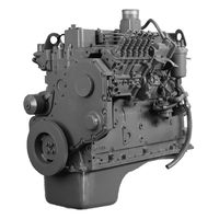
Эти двигатели просты в обслуживании, надежны и имеют высокий показатель эксплуатационной рентабельности. Двигатель Cummins серии B устанавливается на средние грузовики, автобусы, легкую строительную технику.
Экологический стандарт:
Евро-1
Тип двигателя:
дизельный с турбонаддувом
Мощность, кВт (лс):
95 (130)
при частоте вращения, об/мин:
2200
Максимальный крутящий момент, Н·м:
526
при частоте вращения, об/мин:
1600
Гарабиты (ДхШхВ), мм:
1017x632x958
Масса двигателя, нетто, кг:
432
Применяемость:
КАМАЗ, НЕФАЗ, ПАЗ, КАВЗ, ГАЗ, и другие
Руководство по ремонту и эксплуатации двигателя Cummins серии 6BT5.9-C130
Полный список моделей
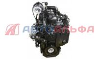
Эти двигатели просты в обслуживании, надежны и имеют высокий показатель эксплуатационной рентабельности. Двигатель Cummins серии B устанавливается на средние грузовики, автобусы, легкую строительную технику.
Серия:
ISB5.9
Экологический стандарт:
Евро-1
Тип двигателя:
дизельный с турбонаддувом
Количество цилиндров:
6
Расположение:
рядное
Мощность, кВт (лс):
95 (130)
при частоте вращения, об/мин:
2200
Максимальный крутящий момент, Н·м:
526
при частоте вращения, об/мин:
1600
Объем, л:
5,9
Диаметр цилиндра:
102
Ход поршня:
120
Степень сжатия:
17.1:1
Гарабиты (ДхШхВ), мм:
1017x632x958
Масса двигателя, нетто, кг:
432
Применяемость:
и другие
- Manuals
- Brands
- CUMMINS Manuals
- Engine
- B5.9 Series
Manuals and User Guides for CUMMINS B5.9 Series. We have 3 CUMMINS B5.9 Series manuals available for free PDF download: Service Manual, Installation Manual, Operation And Maintenance Manual
CUMMINS B5.9 Series Service Manual (741 pages)
Brand: CUMMINS
|
Category: Engine
|
Size: 54.8 MB
Table of Contents
-
Product View
2
-
Table of Contents
4
-
Introduction
6
-
Section Contents
6
-
Introduction
7
-
B3.9, B4.5, B4.5 RGT, and
7
-
About the Manual
8
-
General Information
8
-
General Information
9
-
How to Use the Manual
9
-
Symbols
10
-
Illustrations
11
-
General Safety Instructions
12
-
General Repair Instructions
14
-
Welding on a Vehicle with an Electronic Controlled Fuel System
15
-
-
Abrasive Pads and Abrasive Paper
16
-
Definition of Clean
16
-
General Cleaning Instructions
16
-
Gasket Surfaces
17
-
Solvent and Acid Cleaning
17
-
Plastic Bead Cleaning
18
-
Steam Cleaning
18
-
Fuel System
19
-
Acronyms and Abbreviations
21
-
-
General Information
21
-
Fuel System — Group 05
24
-
Service Tools
28
-
AFC Assembly (005-001)
30
-
Engine Fuel Heater, Electric (005-008)
30
-
Preparatory Steps
30
-
Initial Check
30
-
Finishing Steps
32
-
Measure
33
-
Fuel Consumption (005-010)
33
-
Fuel Flow (005-011)
36
-
Pressure Test
36
-
Fuel Injection Pumps, In-Line (005-012)
38
-
-
Fuel System — Group
39
-
Fuel Injection Pump (In-Line Type)
41
-
Prime
49
-
Fuel Injection Pump, In-Line, Spill Port Timing (005-013)
50
-
Injection Pumps — Venting
50
-
Time
50
-
QD Contact Cleaner, Part Number 3824510
56
-
Plunger Lift Timing
57
-
Fuel Injection Pump, Rotary (005-014)
66
-
Fuel Injection Pump (Distributor Type)
67
-
Advance Timing Mechanism
68
-
Distributor-Type Pump Governor
68
-
Manual Shutdown Levers
68
-
Electrical Shutoff Valves
69
-
Front Gear Train
70
-
Rotary Distributor Type Fuel Injection Pumps
70
-
Bosch® VE
71
-
Lucas CAV DPA Pump and Delphi DP210
71
-
Stanadyne DB4 Pump
71
-
Rear Gear Train
72
-
Tier 2/Stage II Timing Adjustment
80
-
Fuel Pump Control Lever and Spring (005-018)
85
-
Fuel Pump High Idle Speed (005-028)
85
-
Fuel Pump Idle Speed (005-029)
85
-
Bosch® RSV Governor
87
-
Bosch® RQV and RQV-K Governor
88
-
Fuel Pump Support Bracket (005-033)
88
-
Bosch®; and Stanadyne Rotary Pumps
89
-
Four-Cylinder
89
-
In-Line Fuel Injection Pumps
89
-
Fuel Pump Timing (005-037)
91
-
CAV DPA/DPS Fuel Injection Pump Timing
97
-
Bosch® VE Pumps with Round Mounting Holes
98
-
Bosch® VE Pumps with Slotted Mounting Holes
98
-
Fuel Shutoff Valve (005-043)
100
-
Bosch® a Pump with RSV Governor
102
-
-
Lucas CAV DPA or DPS
103
-
Stanadyne DB4
103
-
Voltage Checking
103
-
Bosch® VE
104
-
Delivery Valves (Back Leakage Valves on Lucas CAV Pumps)
104
-
Bosch® P Pump with RQVK Governor
107
-
-
Install
107
-
Stanadyne DB4
108
-
Bosch® a Pump with RSV Governor
109
-
Bosch® P Pump with RQVK Governor
111
-
Fuel Lift Pump (005-045)
112
-
Cold Start Timing Advance System (KSB) Remote (005-046)
116
-
Wax-Motor Style
116
-
Electrical Solenoid-Style KSB
117
-
KSB Hardware Definition
117
-
Remote Mounted KSB
117
-
Wax Motor Style KSB
117
-
Electrical Solenoid Style
118
-
Wax Motor-Style KSB
118
-
Assemble
122
-
Test
122
-
Resistance Check
123
-
Adjust
125
-
Speed Droop Governor (005-058)
125
-
Stanadyne DB4 (Generator Application) Speed Droop Governor
125
-
Fuel Pump Back Leakage Valve (005-059)
126
-
Speed Droop Adjustment
126
-
Inspect for Reuse
127
-
Clean and Inspect for Reuse
128
-
Fuel Pump Pressure Regulator (005-060)
128
-
Cold Start Timing Advance System Temperature Switch (005-069)
129
-
Cold Start Timing Advance System Pump Mounted (005-070)
132
-
Pump-Mounted KSB
133
-
Cold Start Timing Advance System (KSB)
134
-
Pump-Mounted Wax Motor-Style KSB
135
-
Injectors and Fuel Lines — Group 06
140
-
Injectors and Fuel Lines
142
-
-
Service Tools
142
-
AFC Air Tube (006-001)
144
-
Air in Fuel (006-003)
146
-
Fuel Drain Line Restriction (006-012)
148
-
Drain
149
-
Fuel Filter (Spin-On Type) (006-015)
149
-
Low Pressure Fuel Line(S)
153
-
Fuel Filter Head (006-017)
154
-
Fuel Inlet Restriction (006-020)
157
-
Fuel Manifold (Drain) (006-021)
158
-
Distributor-Type Pump
159
-
In-Line Pump
160
-
-
Install
161
-
Fuel Supply Lines (006-024)
162
-
Remove
162
-
Install
165
-
Low Pressure Fuel Line(S)
165
-
Injector (006-026)
167
-
Rust-Penetrating Solvent
169
-
O-Rings and Sealing Washers
172
-
Chatter Test
174
-
Leakage Test
174
-
-
Canister Type
188
-
Drain
188
-
Fuel-Water Separator (006-043)
188
-
Fuel Return Overflow Valve (006-044)
189
-
-
Spin-On Type
189
-
General Information
190
-
Injector Supply Lines (High Pressure) (006-051)
190
-
Finishing Steps
197
-
Fuel Connector (Headmounted) (006-052)
197
-
Preparatory Steps
198
-
Remove
198
-
Lubricating Oil System — Group 07
202
-
Lubricating Oil System
204
-
-
Service Tools
204
-
Clean and Inspect for Reuse
206
-
Engine Oil Heater (007-001)
206
-
Finishing Steps
207
-
Install
207
-
Lubricating Oil Cooler (007-003)
208
-
Clean and Inspect for Reuse
210
-
Finishing Steps
212
-
Lubricating Oil Dipstick (007-009)
213
-
General Information
214
-
Lubricating Oil Dipstick Tube (007-011)
214
-
Preparatory Steps
214
-
Remove
214
-
Lubricating Oil Filter (Spin-On) (007-013)
216
-
Remove
216
-
Finishing Steps
217
-
Install
217
-
Lubricating Oil Pan (007-025)
217
-
Clean and Inspect for Reuse
220
-
Six-Cylinder
222
-
Finishing Steps
224
-
Lubricating Oil Pressure Regulator (Main Rifle) (007-029)
224
-
Clean and Inspect for Reuse
225
-
Finishing Steps
226
-
Install
226
-
Lubricating Oil Pump (007-031)
227
-
Remove
228
-
Install
231
-
Lubricating Oil Suction Tube (Block-Mounted) (007-035)
233
-
Clean and Inspect for Reuse
234
-
Finishing Steps
235
-
-
Lubricating Oil System — Group 07
236
-
Drain
238
-
Fill
238
-
Lubricating Oil Contamination (007-044)
240
-
General Information
245
-
Low-Lubricating Oil Pressure
245
-
Lubricating Oil Pressure Regulating Valve
245
-
Lubricating Oil System Diagnostics (007-048)
245
-
Lubricating Oil Coolers
246
-
Lubricating Oil Filter Bypass Valve
246
-
Bearings and Lubricating Oil Pump
247
-
Incorrect Lubricating Oil Pump
247
-
Lubricating Oil Gauge
247
-
Lubricating Oil Suction Tube
247
-
Lubricating Oil Leaks
248
-
Lubricating Oil Pressure Sensor, OEM (007-052)
249
-
Lubricating Oil and Filter Analysis (007-083)
250
-
Cooling System
252
-
-
Service Tools
256
-
Drive Belt, Cooling Fan (008-002)
258
-
Coolant Heater (008-011)
261
-
Coolant Thermostat (008-013)
267
-
Cooling System (008-018)
276
-
Flush
278
-
Cooling System — Air or Combustion Gas Test (008-019)
282
-
Combustion Gas Leak
283
-
Fan, Shutter, or Heater Air Control Valve
283
-
Air Compressor
284
-
Combustion Gas Leak Test Kit, Part Number 3822985
285
-
Cooling System Diagnostics (008-020)
288
-
Water Pump
290
-
Radiator, Fans, and Shutters
291
-
Gauges, Overfueling, and Loading
293
-
Fan Clutch, Electric (008-026)
294
-
Fan Hub, Belt Driven (008-036)
298
-
Fan Shroud Assembly (008-038)
301
-
Fan Spacer and Pulley (008-039)
301
-
Fan, Cooling (008-040)
304
-
Radiator (008-042)
305
-
Pressure Caps
306
-
Radiator Hoses (008-045)
306
-
Radiator Pressure Cap (008-047)
306
-
Radiator Shutter Assembly (008-049)
308
-
Heat Exchanger (008-053)
309
-
Sea Water Pump (008-057)
311
-
-
General Information
315
-
Water Pump (008-062)
315
-
Initial Check
316
-
Install
318
-
Coolant Temperature Sensor (008-070)
319
-
Preparatory Steps
319
-
Remove
319
-
Water Inlet Connection (008-082)
321
-
Cooling Fan Belt Tensioner (008-087)
323
-
Sea Water Hoses (008-104)
327
-
-
Drive Units — Group 09
328
-
Accessory Drive (009-001)
330
-
Clean and Inspect for Reuse
330
-
Disassemble
331
-
Finishing Steps
334
-
Initial Check
334
-
Install
334
-
Hydraulic Pump Drive (009-016)
335
-
Remove
335
-
Accessory Drive Cover (009-039)
338
-
Clean
338
-
Preparatory Steps
338
-
Remove
338
-
Finishing Steps
339
-
Install
339
-
Air Intake System
340
-
Aftercooler (010-001)
346
-
-
Preparatory Steps
346
-
Remove
346
-
Air Crossover (010-019)
348
-
Air Intake Manifold (010-023)
349
-
Air Leaks, Air Intake and Exhaust Systems (010-024)
354
-
Damage from Nonfiltered Air
356
-
Turbocharger Engines — Air Leaks, Pressure Side
357
-
Charge-Air Cooler (010-027)
357
-
Temperature Differential Test
360
-
Air Intake Restriction (010-031)
361
-
Turbocharger (010-033)
362
-
Axial Clearance Check
363
-
Radial Clearance Check
364
-
Turbocharger Oil Drain Line (010-045)
371
-
Turbocharger Oil Supply Line (010-046)
373
-
Turbocharger Wastegate Actuator (010-050)
375
-
Calibrate
379
-
Turbocharger Wastegate Valve Body (010-055)
380
-
Intake Manifold Pressure (010-057)
381
-
Air Intake Manifold Heater (010-072)
382
-
Air Intake Heater Controller Interconnection Diagram
384
-
Cold Starting System
385
-
Grid Heater Component Connections
385
-
6B Industrial Grid Heater
387
-
Maintenance Check
389
-
Intake Manifold Air Heater Wiring Harness (010-122)
393
-
Intake Manifold Air Heater Temperature Sensor (010-123)
397
-
Intake Manifold Air Heater Element (010-124)
398
-
Intake Manifold Air Heater Control Module (010-125)
403
-
Post Heat Cycle
405
-
Post Heat Recycle
407
-
Intake Manifold Air Heater Solenoid Switch (010-126)
409
-
Intake Manifold Air Heater Speed Sensor (010-127)
411
-
Air Intake Connection Adapter (010-131)
414
-
Exhaust System
418
-
-
Exhaust System — Group
419
-
Exhaust Manifold, Dry (011-007)
421
-
Exhaust Restriction (011-009)
424
-
Compressed Air System
426
-
-
Compressed Air System — Group
427
-
Air Compressor Carbon Build up (012-003)
430
-
Air Compressor Coolant Lines (012-004)
431
-
Air Compressor Pin Bore Wear (012-010)
432
-
Air Compressor Unloader and Valve Assembly (012-013)
435
-
Air Compressor (012-014)
439
-
Compressor Timing Procedure
442
-
Air Governor (Air Compressor will Notpump) (012-017)
444
-
Air Governor (Air Compressor Pumps Continuously) (012-018)
445
-
Air Compressor Cylinder Head (Holset® SS191 Model) (012-101)
447
-
Air Leaks, Compressed Air System (012-019)
447
-
Air Compressor Seat Socket, Part Number 3823528
451
-
Valve Discs
452
-
Inlet Valve Seat
452
-
Exhaust Valve Seat
453
-
Inlet Valve Cage
453
-
Measure the Valve Guide Diameter
454
-
Measure the Top of the Cage to the Valve Stop
454
-
Exhaust Valve Stop
454
-
Unloader Pin
455
-
Valve Springs
455
-
Cylinder Head
456
-
Spring Data
456
-
Air Compressor Cylinder Head (Holset® QE Models) (012-104)
461
-
E-Type Air Compressor
461
-
E-Type System with Air Dryer
461
-
E-Type System Without Air Dryer
462
-
QE, European
473
-
Electrical Equipment
480
-
-
Electrical Equipment — Group
481
-
Alternator (013-001)
483
-
One Wire System, Typical Alternator (Delco-Remy™) with Combined Metri-Pack™ Connector
483
-
Three Wire System, Typical Alternator (Delco-Remy™)
484
-
One Wire System, Typical Alternator (Delco-Remy™)
484
-
Typical Alternator (Bosch™ K1)
485
-
Spool Mount
489
-
Hinge Mount
489
-
Bosch™ K1 Alternator
491
-
Alternator Bracket (013-003)
491
-
Alternator Pulley (013-006)
495
-
Batteries (013-007)
496
-
Battery Cables and Connections (013-009)
500
-
Starter Magnetic Switch (013-017)
501
-
Starter Switch (013-018)
503
-
Starter Solenoid (013-019)
505
-
Solenoid Control Circuit Voltage Drop on Delco® Starters
508
-
Starting Motor (013-020)
511
-
Cummins® Branded Starters
515
-
Non-Cummins® Branded Starters
515
-
Engine Testing
516
-
-
Engine Testing — Group
517
-
Engine Testing (Chassis Dynamometer) (014-002)
520
-
Engine Run-In (Chassis Dynamometer) (014-003)
526
-
Engine Run-In (Without Dynamometer) (014-004)
527
-
On-Highway Applications
527
-
Off-Highway Applications
528
-
Engine Lifting Fixture, Part Number 3822512
529
-
Engine Testing (Engine Dynamometer) (014-005)
529
-
Water Manometer, Part Number ST-1111-3
530
-
Air Inlet Restriction
530
-
Pressure Gauge, Part Number ST-1273
530
-
Exhaust Restriction
530
-
Blowby Checking Tool, Part Number 3822476
534
-
Vacuum Gauge, Part Number ST-434
534
-
Engine Run-In (Engine Dynamometer) (014-006)
535
-
Engine Testing (in Chassis) (014-008) Initial Check
539
-
B3.9, B5.9, and B4.5 Engines
539
-
Piston Ring Sealing
540
-
Intake and Exhaust Valve Sealing
540
-
B4.5 RGT Engines
541
-
Cylinder Head Gasket Sealing
541
-
Crankcase Blowby, Measure (014-010)
544
-
Blowby Conversion Table (5.61-MM [0.221-In] Orifice, Blowby Tool, Part Number 3822476)
546
-
Blowby Conversion Table (7.67-MM [0.302-In] Orifice, Blowby Tool, Part Number 3822566)
547
-
Midrange Blowby Specifications Chart
549
-
Engine Blowby Contribution
555
-
Turbocharger Blowby Contribution
556
-
Preferred Turbocharger Isolation Method
557
-
Air Compressor Blowby Contribution
561
-
Exhaust Brake Blowby Contribution
564
-
Base Engine Component Blowby Contribution
565
-
Air Compressor Is Malfunctioning
568
-
Piston or Piston Rings Are Worn or Damaged
569
-
Mounting Adaptations
570
-
Engine Support Bracket, Front (016-002)
574
-
Engine Support Bracket, Rear (016-003)
576
-
Flexplate (016-004)
578
-
Mechanical
579
-
Electrical
579
-
Flywheel (016-005)
581
-
Bore Runout
587
-
Face Runout
588
-
Flywheel Housing (016-006)
590
-
All Applications
591
-
Face Alignment
596
-
Determine the Total Indicator Reading (TIR)
597
-
Bore Alignment
599
-
Flywheel Ring Gear (016-008)
606
-
Engine Mounts (016-010)
607
-
Propeller Shaft (016-025)
607
-
Out of Water
608
-
Specifications
609
-
Marine Vibration Isolator (016-026)
610
-
Miscellaneous
616
-
-
Miscellaneous — Group
617
-
Cup Plug (017-002)
620
-
Pipe Plug (017-007)
621
-
Straight Thread Plug (017-011)
623
-
Expansion Plug (017-015)
625
-
Coolant Passages
626
-
Service Literature
628
-
-
Service Literature
629
-
Additional Service Literature
630
-
Contact Information
631
-
Cummins Customized Parts Catalog
632
-
-
Specifications
634
-
Cylinder Block — Group 01 — Specifications
638
-
Cylinder Block — Group 01 — Torque Values
648
-
Cylinder Head — Group 02 — Specifications
654
-
Cylinder Head — Group 02 — Torque Values
657
-
Rocker Levers — Group 03 — Specifications
659
-
Rocker Levers — Group 03 — Torque Values
660
-
Cam Followers/Tappets — Group 04 — Specifications
663
-
Cam Followers/Tappets — Group 04 — Torque Values
664
-
Fuel System — Group 05 — Specifications
665
-
Fuel System — Group 05 — Torque Values
666
-
Injectors and Fuel Lines — Group 06 — Specifications
674
-
Injectors and Fuel Lines — Group 06 — Torque Values
675
-
Lubricating Oil System — Group 07 — Specifications
679
-
Lubricating Oil System — Group 07 — Torque Values
681
-
Cooling System — Group 08 — Specifications
682
-
Cooling System — Group 08 — Torque Values
683
-
Drive Units — Group 09 — Specifications
686
-
Drive Units — Group 09 — Torque Values
687
-
Air Intake System — Group 10 — Specifications
688
-
Air Intake System — Group 10 — Torque Values
689
-
Exhaust System — Group 11 — Specifications
692
-
Exhaust System — Group 11 — Torque Values
693
-
Compressed Air System — Group 12 — Specifications
694
-
Compressed Air System — Group 12 — Torque Values
696
-
Electrical Equipment — Group 13 — Specifications
699
-
Electrical Equipment — Group 13 — Torque Values
700
-
Mounting Adaptations — Group 16 — Specifications
702
-
Mounting Adaptations — Group 16 — Torque Values
703
-
General Engine
705
-
Fuel System
707
-
Lubricating Oil System
708
-
Cooling System Specifications
710
-
Air Intake System Specifications
711
-
Exhaust System Specifications
717
-
Electrical System Specifications
718
-
Compressed Air System Specifications
720
-
Engine Testing Specifications
722
-
Cummins®/Fleetguard® Filter Specifications
723
-
Fuel Recommendations and Specifications
724
-
Drive Belt Tension
725
-
Engine Component Torque Values
726
-
Capscrew Markings and Torque Values
727
-
Fraction, Decimal, Millimeter Conversions
729
-
Newton-Meter to Foot-Pound Conversions
730
-
Pipe Plug Torque Values
731
-
Tap-Drill Chart — U.S. Customary and Metric
732
-
Weights and Measures — Conversion Factors
733
-
Index
734
-
Advertisement

CUMMINS B5.9 Series Service Manual (724 pages)
Brand: CUMMINS
|
Category: Portable Generator
|
Size: 38.93 MB

CUMMINS B5.9 Series Installation Manual, Operation And Maintenance Manual (323 pages)
Brand: CUMMINS
|
Category: Engine
|
Size: 9.1 MB
Table of Contents
-
Table of Contents
4
-
Introduction
7
-
To the Owner and Operator
8
-
About the Manual
9
-
How to Use the Manual
10
-
Symbols
11
-
Illustrations
12
-
General Safety Instructions
13
-
General Repair Instructions
15
-
Welding on a Vehicle with an Electronic Controlled Fuel System
16
-
-
General Cleaning Instructions
17
-
Gasket Surfaces
18
-
Plastic Bead Cleaning
19
-
Fuel System
20
-
-
Acronyms and Abbreviations
22
-
-
Engine and System Identification
25
-
Operating Instructions
55
-
Maintenance Guidelines
56
-
Maintenance Procedures at Daily Interval
70
-
Maintenance Procedures at 250 Hours or 3 Months
70
-
Maintenance Procedures at 500 Hours or 6 Months
70
-
Maintenance Procedures at 1000 Hours or 1 Year
70
-
Maintenance Procedures at 2000 Hours or 2 Years
70
-
-
Section 3 — Maintenance Procedures at Daily Interval
74
-
Air Intake Piping
77
-
Maintenance Check
77
-
-
Air Tanks and Reservoirs
77
-
Maintenance Check
78
-
-
Crankcase Breather Tube
78
-
Drain
81
-
Canister Type
81
-
Spin-On Type
82
-
-
-
Lubricating Oil Level
82
-
Maintenance Check
82
-
-
-
Section 4 — Maintenance Procedures at 250 Hours or 3 Months
84
-
Air Cleaner Restriction
86
-
Maintenance Check
86
-
-
Air Compressor
87
-
Maintenance Check
87
-
-
Charge-Air Cooler
87
-
Charge-Air Piping
88
-
Maintenance Check
88
-
-
Closed Crankcase Ventilation Hoses
88
-
Fuel Pump
88
-
Maintenance Procedures — Overview
89
-
Radiator Pressure Cap
89
-
General Information
89
-
Inspect for Reuse
90
-
Pressure Test
90
-
-
-
Radiator Hoses
89
-
-
Section 5 — Maintenance Procedures at 500 Hours or 6 Months
92
-
Engine Coolant Antifreeze
94
-
Maintenance Check
94
-
-
Fuel Filter (Canister Type)
94
-
Preparatory Steps
94
-
Prime
95
-
Remove
95
-
-
Fuel Filter (Spin-On Type)
97
-
Drain
97
-
Install
98
-
Prime
99
-
General Information
99
-
Remove
101
-
-
Lubricating Oil and Filters
101
-
Drain
101
-
-
-
Section 6 — Maintenance Procedures at 1000 Hours or 1 Year
104
-
Cooling Fan Belt Tensioner
106
-
Maintenance Check
106
-
-
Fan Hub, Belt Driven
107
-
Maintenance Check
107
-
-
Overhead Set
109
-
Maintenance Procedures — Overview
109
-
Adjust
109
-
B3.9, B5.9, and B4.5 Engines
109
-
-
Finishing Steps
111
-
-
-
Section 7 — Maintenance Procedures at 2000 Hours or 2 Years
112
-
Air Compressor Discharge Lines
114
-
General Information
114
-
Maintenance Check
114
-
-
Adjustment, Repair, and Replacement
114
-
System Diagrams
114
-
-
Cooling System
115
-
Drain
115
-
Flush
116
-
-
Vibration Damper, Rubber
119
-
Inspect
119
-
-
Maintenance Procedures — Overview
119
-
Vibration Damper, Viscous
120
-
Inspect
120
-
-
-
Section a — Adjustment, Repair, and Replacement
122
-
Air in Fuel
124
-
General Information
124
-
-
Alternator
124
-
Initial Check
124
-
Install
127
-
-
Charge-Air Cooler
127
-
General Information
127
-
Initial Check
127
-
-
Cooling Fan Belt Tensioner
129
-
Inspect for Reuse
129
-
Install
129
-
Remove
129
-
-
Drive Belt, Cooling Fan
130
-
Inspect for Reuse
130
-
Install
131
-
Remove
131
-
-
Fan Spacer and Pulley
131
-
Inspect for Reuse
131
-
Preparatory Steps
131
-
Remove
132
-
-
Starting Motor
132
-
Finishing Steps
133
-
Install
133
-
Service Literature
157
-
Service Assistance
163
-
-
-
Section Ts — Troubleshooting Symptoms
214
-
Troubleshooting Symptoms
215
-
Troubleshooting Procedures and Techniques
216
-
General Information
216
-
-
Troubleshooting Symptoms Charts
217
-
General Information
217
-
Air Compressor Air Pressure Rises Slowly
218
-
Air Compressor Cycles Frequently
219
-
Air Compressor Noise Is Excessive
220
-
Air Compressor Pumping Excess Lubricating Oil into the Air System
221
-
Air Compressor will Not Maintain Adequate Air Pressure (Not Pumping Continuously
222
-
Air Compressor will Not Stop Pumping
223
-
Alternator Not Charging or Insufficient Charging
224
-
Alternator Overcharging
225
-
Coolant Contamination
226
-
Coolant Loss — External
227
-
Coolant Temperature above Normal — Gradual Overheat
228
-
Coolant Temperature above Normal — Sudden Overheat
230
-
Coolant Temperature below Normal
231
-
Engine Acceleration or Response Poor
232
-
Engine Difficult to Start or will Not Start (Exhaust Smoke
234
-
Engine Difficult to Start or will Not Start (no Exhaust Smoke
237
-
Engine Noise Excessive
239
-
Engine Noise Excessive — Combustion Knocks
241
-
Engine Power Output Low
242
-
Engine Runs Rough at Idle
245
-
Engine Runs Rough or Misfires
246
-
Engine Shuts off Unexpectedly or dies During Deceleration
247
-
Engine Speed Surges at Low or High Idle
248
-
Engine Speed Surges under Load or in Operating Range
249
-
Engine Starts but will Not Keep Running
250
-
Engine Vibration Excessive
251
-
Engine will Not Crank or Cranks Slowly (Air Starter
252
-
Engine will Not Crank or Cranks Slowly (Electric Starter
254
-
Engine will Not Reach Rated Speed (RPM
256
-
Engine will Not Shut off
258
-
Exhaust Smoke Excessive under Load
259
-
Fuel Consumption Excessive
260
-
Fuel in Coolant
261
-
Fuel in the Lubricating Oil
262
-
Fuel or Lubricating Oil Leaking from Exhaust Manifold
263
-
Intake Manifold Air Temperature above Specification
264
-
Intake Manifold Pressure (Boost) Is below Normal
266
-
Lubricating Oil Consumption Excessive
267
-
Lubricating Oil Contaminated
268
-
Lubricating Oil Loss
269
-
Lubricating Oil Pressure High
270
-
Lubricating Oil Pressure Low
271
-
Lubricating Oil Sludge in the Crankcase Excessive
273
-
Smoke, Black — Excessive
274
-
Smoke, White — Excessive
275
-
Turbocharger Leaks Engine Oil or Fuel
277
-
Maintenance Specifications
279
-
Warranty
307
-
All Engines United States and Canada Industrial (Off-Highway
308
-
All Engines International Industrial (Off-Highway
311
-
California Emission Control System Warranty, Off-Highway
313
-
Owner’s Warranty Responsibilities
315
-
-
-
Advertisement
Advertisement
Related Products
-
CUMMINS B3.3
-
CUMMINS B Series 1991
-
CUMMINS B Series 1994
-
CUMMINS B3.9 Series
-
CUMMINS B4.5 Series
-
CUMMINS B4.5 RGT
-
CUMMINS Big Cam III
-
CUMMINS Big Cam IV
-
CUMMINS B112
-
CUMMINS B109
CUMMINS Categories
Portable Generator
Engine
Inverter
Controller
![]()
Switch
More CUMMINS Manuals
Комментарии
15
Войдите или зарегистрируйтесь, чтобы писать комментарии, задавать вопросы и участвовать в обсуждении.

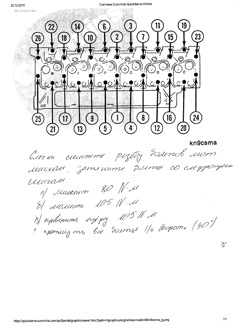
Дружище привет, нашел мануал по таким движкам если да то скинь мне, а то уже все перерыл не могу найти, у меня такой же на камазике 4308 стоит, проблема коленвал ходит вперед назад 2мм, хочу вскрыть потдон и поменять полукольца или что там стоит сам, а то наши местные моторюги за.бали уже кто говорит что что там нет полуколец и что нужно вкладыши менять кто есть и возможно шейки на валу подъело и люфт появился, короче пока сам не разберешься ну его нафиг этих кулибинов

Всем спасибо все нашел!

Там нет 5.9 12 клапанного. Спасибо!

Это клуб владельцев додж рам там вся нужная информация, а если нет то подскажут что и как;)
Я там просто не очень ориентируюсь.

В «Базе знаний» там лежат файлы: мануалы, реклама и т.д. Я наш BR/BE-шный мануал, в свое время, скачал там.
Как вариант: на торрентах можно поискать, их там есть.

Могу на почту выслать )))
9,06 Мб
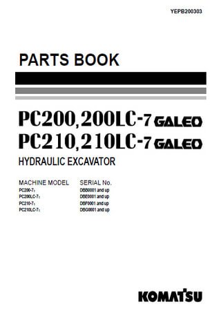
Каталог запчастей экскаваторов Komatsu PC200-7, PC200LC-7,
Формат: pdf
-
Год:
2004
-
Страниц:
536
-
Язык:
английский
-
Размер:
9,06 Мб
-
Категории:
Двигатель Cummins 6BTAA5.9