-
nekesha
- Администратор
- Сообщения: 1668
- Зарегистрирован: 17 дек 2014, 03:43
- Благодарил (а): 2 раза
- Поблагодарили: 6 раз
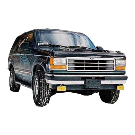
Ford Ranger с 2006г
Сообщение nekesha » 21 фев 2015, 16:59
Руководство по эксплуатации, техобслуживанию и ремонту Mazda BT-50
 2394 просмотра")
Выпуск: с 2006 года
Язык: Русский
Формат: PDF
Размер: 83 Мб
Скачать документацию Mazda BT-50
для распаковки архива используйте пароль — avtoproblem-net.ru
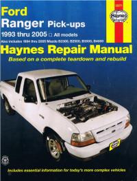
Руководство на английском языке по техническому обслуживанию и ремонту Ford Ranger и Mazda B-series 1993-2005 годов выпуска.
- Автор: —
- Издательство: Haynes Publishing
- Год издания: —
- Страниц: 338
- Формат: PDF
- Размер: 237,8 Mb

Руководство на английском языке по техническому обслуживанию и ремонту Ford Ranger 2003 года выпуска.
- Автор: —
- Издательство: —
- Год издания: —
- Страниц: —
- Формат: PDF
- Размер: 81,8 Mb

Руководство на английском языке по техническому обслуживанию и ремонту Ford Ranger и Mazda Drifter 2006 года выпуска.
- Автор: —
- Издательство: —
- Год издания: —
- Страниц: —
- Формат: PDF
- Размер: 31,1 Mb

Руководство на английском языке по ремонту автомобилей Ford Ranger с 2011 года выпуска.
- Автор: —
- Издательство: Motorist
- Год издания: —
- Страниц: 1427
- Формат: PDF
- Размер: —
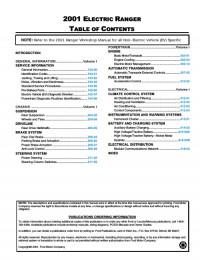
Подборка руководств на английском языке по техническому обслуживанию и ремонту Ford Ranger EV 2001 года выпуска.
- Автор: —
- Издательство: Ford Motor Company
- Год издания: 1999/2001
- Страниц: —
- Формат: PDF
- Размер: 46,0 Mb

Руководство по ремонту и техническому обслуживанию Ford Bronco II/Explorer/Ranger 1983-1994 годов выпуска с бензиновыми и дизельными двигателями.
- Автор: —
- Издательство: ПОНЧиК
- Год издания: 2003
- Страниц: 438
- Формат: DjVu
- Размер: 93,0 Mb

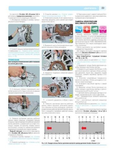
Руководство по эксплуатации, техническому обслуживанию и ремонту Ford Ranger и Mazda BT-50 с 2006 года выпуска дизельными двигателями объемом 2,5/3,0 л.
- Автор: —
- Издательство: АНТА-ЭКО
- Год издания: 2011
- Страниц: 426
- Формат: —
- Размер: —

Подборка руководств по эксплуатации Ford Ranger 2010-2014 г.
- Автор: —
- Издательство: Ford Motor Company
- Год издания: 2010/2012/2013/2014
- Страниц: 166/296/302/310
- Формат: PDF
- Размер: 112,2 Mb

Руководство по техническому обслуживанию и ремонту Ford Explorer, Ford Ranger и Mercury Mountaineer 1991-1999 годов выпуска.
- Автор: —
- Издательство: Легион-Автодата
- Год издания: —
- Страниц: 416
- Формат: —
- Размер: —

Руководство по техническому обслуживанию и ремонту Ford Ranger и Mazda BT-50 с 2006 года выпуска с дизельным двигателем объемом 2,5 л.
- Автор: —
- Издательство: Легион-Автодата
- Год издания: —
- Страниц: 280
- Формат: —
- Размер: —

Не знаю, как у других, а я вот с трудом нашел сервисные мануалы по ремонту. Нашлись не в рунете, а у буржуев.
Делюсь с общественностью, т.к. вдруг кто-то еще испытывает затруднения с поиском инфы по ремонту.
Да, кстати, мануалы на родном англицком  Но, что не может не радовать, размеры всяческие там указаны в миллиметрах и дюймах, так что пересчитывать не придется.
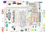
Электрика (часть 1)
Электрика (часть 2)
Механика (часть 1)
Механика (часть 2)
Техническая документация по ремонту автомобилей Ford Ranger
( все годы выпуска) Бесплатно, без регистрации и СМС
Руководство по ремонту, эксплуатации и техническому обслуживанию Ford Ranger
— полные технические характеристики Ford Ranger
— особенности эксплуатации
— устранение неисправностей Ford Ranger
— цветные электросхемы
СКАЧАТЬ / СКАЧАТЬ С ЗЕРКАЛА
Руководство по эксплуатации Ford Ranger
— полные технические характеристики Ford Ranger
— особенности эксплуатации
— устранение неисправностей Ford Ranger
— цветные электросхемы
СКАЧАТЬ / СКАЧАТЬ С ЗЕРКАЛА
Руководство по ремонту в фотографиях Ford Ranger
— полные технические характеристики Ford Ranger
— особенности эксплуатации
— устранение неисправностей
— более 2000 фотографий процесса ремонтаFord Ranger
СКАЧАТЬ / СКАЧАТЬ С ЗЕРКАЛА
Каталог деталей и сборочных единиц Ford Ranger
— таблица взаимозаменяемости деталей автомобилей
— предназначен для работников СТО и владельцев автомобилей Ford Ranger
— каталог деталей
СКАЧАТЬ / СКАЧАТЬ С ЗЕРКАЛА
Подробная электросхема Ford Ranger
— полное описание электрооборудования
— подробно описан алгоритм поиска неисправностей электрооборудования (стартер, генератор, система зажигания)
— подробная схема электрооборудования ( электро схема ) Ford Ranger
СКАЧАТЬ / СКАЧАТЬ С ЗЕРКАЛА
Руководство по ремонту двигателя Ford Ranger
— полные технические характеристики двигателя Ford Ranger
— особенности конструкции и ремонта двигателя Ford Ranger
— устранение неисправностей двигателя своими руками
— подробное описание процессов разборки, дефектовки и сборки двигателя с фотографиями
СКАЧАТЬ / СКАЧАТЬ С ЗЕРКАЛА
Руководство по ремонту коробок передач КПП Ford Ranger
— полные технические характеристики КПП Ford Ranger
— особенности конструкции и ремонта КПП Ford Ranger
— устранение неисправностей КПП
— подробное описание процессов разборки, дефектовки и сборки КПП с фотографиями
Коды ошибок инжектора Ford Ranger
— описание и схема инжектора
— расшифровка кодов неисправностей двигателя Ford Ranger
— устранение неисправностей инжектора
— цветные электросхемы
Руководство по тюнингу Ford Ranger
— тюнинг своими руками Ford Ranger
— тюнинг двигателя
— тюнинг кузова
— тюнинг подвески
а вот здесь можно заработать на новую машину, и тогда старую не придется ремонтировать!!!
Скачать все одним файлом с depositfiles
Скачать все одним файлом с turbobit
- Manuals
- Brands
- Ford Manuals
- Automobile
- RANGER
- Maintaince and repair manual
-
Contents
-
Table of Contents
-
Troubleshooting
-
Bookmarks
Quick Links
ChiltonDIY Maintaince and Repair Manual
Ford Explorer 1991−1999
Related Manuals for Ford Ranger
Summary of Contents for Ford Ranger
-
Page 1
ChiltonDIY Maintaince and Repair Manual Ford Explorer 1991−1999… -
Page 2: Table Of Contents
HOW TO USE THIS BOOK Table of Contents HOW TO USE THIS BOOK……………………..1 Introduction…………………………1 Where to Begin……………………….1 Avoiding Trouble………………………..1 Maintenance or Repair?………………………1 Avoiding the Most Common Mistakes………………..2 TOOLS AND EQUIPMENT……………………..3 Introduction…………………………3 Special Tools ……………………….11 SERVICING YOUR VEHICLE SAFELY…………………13 Introduction……………………….13 Do’s…………………………..14 Don’ts…………………………15 FASTENERS, MEASUREMENTS AND CONVERSIONS……………..17 Bolts, Nuts and Other Threaded Retainers………………..17…
-
Page 3
HOW TO USE THIS BOOK Table of Contents ROUTINE MAINTENANCE AND TUNE−UP Belts………………………….57 INSPECTION ……………………..57 ADJUSTMENT……………………..59 REMOVAL & INSTALLATION………………..63 Timing Belts……………………….68 INSPECTION ……………………..68 CAMSHAFT TIMING INSPECTION……………….72 Hoses…………………………72 INSPECTION ……………………..72 REMOVAL & INSTALLATION………………..74 CV−Boots………………………..76 INSPECTION ……………………..76 Spark Plugs……………………….77 SPARK PLUG HEAT RANGE………………….78 REMOVAL &… -
Page 4
HOW TO USE THIS BOOK Table of Contents FLUIDS AND LUBRICANTS DRAIN & REFILL ……………………113 Automatic Transmission……………………114 FLUID RECOMMENDATION………………..114 LEVEL CHECK……………………..114 DRAIN, PAN/FILTER SERVICE & REFILL…………….116 Transfer Case……………………….123 FLUID RECOMMENDATION………………..123 LEVEL CHECK……………………..123 DRAIN & REFILL ……………………125 Front and Rear Drive Axle ……………………125 FLUID RECOMMENDATION………………..125 LEVEL CHECK……………………..126 DRAIN &… -
Page 5
HOW TO USE THIS BOOK Table of Contents JACKING…………………………..159 SPECIFICATION CHARTS…………………….163 DISTRIBUTOR IGNITION SYSTEM………………….169 General Information……………………..169 SYSTEM OPERATION ……………………170 Diagnosis and Testing……………………..171 SERVICE PRECAUTIONS………………….171 PRELIMINARY CHECKS………………….171 TEST PROCEDURES……………………171 Ignition Coil……………………….177 TESTING……………………….177 REMOVAL & INSTALLATION………………..180 Ignition Control Module (ICM)………………….180 REMOVAL & INSTALLATION………………..180 Distributor……………………….182 REMOVAL &… -
Page 6
HOW TO USE THIS BOOK Table of Contents SENDING UNITS……………………….237 Introduction……………………….237 Coolant Temperature Sender…………………..237 TESTING……………………….237 REMOVAL & INSTALLATION………………..239 Oil Pressure Sender and Switch………………….241 TESTING……………………….241 REMOVAL & INSTALLATION………………..243 Low Oil Level Sensor……………………..245 TESTING……………………….245 REMOVAL & INSTALLATION………………..246 SPECIFICATION CHARTS…………………….249 ENGINE MECHANICAL ……………………..251 Engine…………………………251 REMOVAL &… -
Page 7
HOW TO USE THIS BOOK Table of Contents ENGINE MECHANICAL Camshaft and Auxiliary Shaft Sprockets and Seals …………….408 REMOVAL & INSTALLATION………………..408 Camshafts, Bearings and Lifters………………….408 REMOVAL & INSTALLATION………………..408 INSPECTION ……………………..421 BEARING REMOVAL & INSTALLATION…………….424 Auxiliary Shaft ………………………..427 REMOVAL & INSTALLATION………………..427 Rear Main Oil Seal . -
Page 8
HOW TO USE THIS BOOK Table of Contents EMISSION CONTROLS OPERATION……………………..515 COMPONENT TESTING………………….516 REMOVAL & INSTALLATION………………..523 Exhaust Gas Recirculation (EGR) System………………524 OPERATION……………………..524 COMPONENT TESTING………………….525 REMOVAL & INSTALLATION………………..529 ELECTRONIC ENGINE CONTROLS…………………..533 Electronic Engine Control (EEC)………………….533 Powertrain Control Module (PCM)…………………533 OPERATION……………………..533 REMOVAL & INSTALLATION………………..534 Heated Oxygen Sensors (HO2S)………………….537 OPERATION……………………..537 TESTING……………………….538… -
Page 9
HOW TO USE THIS BOOK Table of Contents COMPONENT LOCATIONS……………………567 TROUBLE CODES……………………….581 General Description……………………..581 FAILURE MODE EFFECTS MANAGEMENT (FMEM)…………582 HARDWARE LIMITED OPERATION STRATEGY (HLOS)………..582 MALFUNCTION INDICATOR LAMP (MIL)…………….582 Diagnostic Connector ………………………582 Reading Codes………………………..583 EEC−V EQUIPPED ENGINES………………..584 EEC−IV EQUIPPED ENGINES………………..584 Clearing Codes………………………..586 CONTINUOUS MEMORY CODES………………..586 KEEP ALIVE MEMORY………………….586… -
Page 10
HOW TO USE THIS BOOK Table of Contents FUEL TANK…………………………641 Tank Assembly……………………….641 REMOVAL & INSTALLATION………………..641 Sending Unit……………………….647 REMOVAL & INSTALLATION………………..647 UNDERSTANDING AND TROUBLESHOOTING ELECTRICAL SYSTEMS……..649 Basic Electrical Theory……………………649 HOW DOES ELECTRICITY WORK: THE WATER ANALOGY……….649 OHM’S LAW ……………………..650 Electrical Components…………………….651 POWER SOURCE……………………651 GROUND……………………….651 PROTECTIVE DEVICES ………………….651… -
Page 11
HOW TO USE THIS BOOK Table of Contents CRUISE CONTROL……………………….685 Vacuum Controlled Systems…………………..685 Electronic Systems……………………..685 ENTERTAINMENT SYSTEMS……………………687 Radio Receiver/Tape Player……………………687 REMOVAL & INSTALLATION………………..687 Speakers………………………….689 REMOVAL & INSTALLATION………………..689 WINDSHIELD WIPERS……………………..693 Wiper Arm And Blade…………………….693 REMOVAL & INSTALLATION………………..693 Windshield Wiper Motor……………………695 REMOVAL & INSTALLATION………………..695 Windshield Washer Motor……………………701 REMOVAL &… -
Page 12
HOW TO USE THIS BOOK Table of Contents MANUAL TRANSMISSION…………………….755 Understanding the Manual Transmission………………..755 Identification……………………….755 Adjustments……………………….755 SHIFTER & LINKAGE ADJUSTMENTS………………756 Shift Handle……………………….756 REMOVAL & INSTALLATION………………..756 Neutral Sensing Switch……………………757 REMOVAL & INSTALLATION………………..758 Extension Housing Seal……………………759 REMOVAL & INSTALLATION………………..759 Transmission……………………….760 REMOVAL & INSTALLATION………………..760 CLUTCH……………………………763 Understanding the Clutch……………………763 Clutch Interlock Switch……………………764… -
Page 13
HOW TO USE THIS BOOK Table of Contents DRIVELINE…………………………801 General Description……………………..801 Single Cardan Type Front Driveshaft………………..801 REMOVAL & INSTALLATION………………..801 DUST SLINGER/BOOT REPLACEMENT ……………..803 Double Cardan Type Front and Rear Driveshaft……………..803 REMOVAL & INSTALLATION………………..803 DISASSEMBLY & ASSEMBLY………………..804 Single Cardan Type Rear Driveshaft………………..806 REMOVAL &… -
Page 14
HOW TO USE THIS BOOK Table of Contents 2−WHEEL DRIVE FRONT SUSPENSION………………..855 Introduction……………………….855 Coil Springs……………………….856 REMOVAL & INSTALLATION………………..856 Torsion Bars……………………….858 REMOVAL & INSTALLATION………………..858 RIDE HEIGHT ADJUSTMENT ………………..860 Shock Absorbers……………………..861 REMOVAL & INSTALLATION………………..861 TESTING……………………….864 Ball Joints……………………….865 INSPECTION ……………………..865 REMOVAL & INSTALLATION………………..866 Knuckle and Spindle……………………..868 REMOVAL &… -
Page 15
HOW TO USE THIS BOOK Table of Contents 4−WHEEL DRIVE FRONT SUSPENSION I−Beam Axle……………………….910 Upper Control Arm……………………..910 REMOVAL & INSTALLATION………………..910 Lower Control Arm ……………………..912 REMOVAL & INSTALLATION………………..912 Front Wheel Bearings……………………..914 REMOVAL & INSTALLATION………………..914 ADJUSTMENT……………………..925 Wheel Alignment……………………..927 REAR SUSPENSION………………………..929 Introduction……………………….929 Leaf Springs……………………….930 REMOVAL &… -
Page 16
HOW TO USE THIS BOOK Table of Contents BRAKE OPERATING SYSTEM DRUM BRAKES……………………..973 Brake Light Switch……………………..973 REMOVAL & INSTALLATION………………..973 Master Cylinder………………………974 REMOVAL & INSTALLATION………………..974 Power Booster……………………….978 REMOVAL & INSTALLATION………………..978 Brake Hoses and Lines …………………….983 REMOVAL & INSTALLATION………………..983 Bleeding The Brakes……………………..985 FRONT DISC BRAKES ……………………..989 Introduction……………………….989 Brake Pads……………………….990… -
Page 17
HOW TO USE THIS BOOK Table of Contents REAR ANTI−LOCK BRAKE SYSTEM (RABS) REMOVAL & INSTALLATION………………..1045 RABS Valve……………………….1045 REMOVAL & INSTALLATION………………..1045 RABS Sensor………………………..1045 TESTING……………………….1046 REMOVAL & INSTALLATION………………..1046 Exciter Ring……………………….1047 PARKING BRAKE……………………….1049 Cable…………………………1049 ADJUSTMENT………………………1049 REMOVAL & INSTALLATION………………..1053 Brake Shoes……………………….1059 REMOVAL & INSTALLATION………………..1059 ADJUSTMENT………………………1060 4−WHEEL ANTI−LOCK BRAKE SYSTEM (4WABS)…………….1063 Introduction……………………….1063… -
Page 18
HOW TO USE THIS BOOK Table of Contents EXTERIOR Grille…………………………1088 REMOVAL & INSTALLATION………………..1089 Outside Mirrors……………………..1090 REMOVAL & INSTALLATION………………..1090 Antenna…………………………1092 REMOVAL & INSTALLATION………………..1092 Fenders………………………….1094 REMOVAL & INSTALLATION………………..1094 Pickup Truck Bed……………………..1096 REMOVAL & INSTALLATION………………..1096 Chassis and Cab Mount Bushings…………………1097 REMOVAL & INSTALLATION………………..1097 Spare Tire Carrier……………………..1101 REMOVAL &… -
Page 19: How To Use This Book
This Chilton’s Total Car Care manual is intended to help you learn more about the inner workings of your Ranger, Explorer or Mountaineer while saving you money on its upkeep and operation. The beginning of the book will likely be referred to the most, since that is where you will find information for maintenance and tune−up.
-
Page 20: Avoiding The Most Common Mistakes
HOW TO USE THIS BOOK CHEAPER THAN REPAIR. Two basic mechanic’s rules should be mentioned here. First, whenever the left side of the vehicle or engine is referred to, it means the driver’s side. Conversely, the right side of the vehicle means the passenger’s side. Second, screws and bolts are removed by turning counterclockwise, and tightened by turning clockwise unless specifically noted.
-
Page 21: Tools And Equipment
TOOLS AND EQUIPMENT Introduction Without the proper tools and equipment it is impossible to properly service your vehicle. It would be virtually impossible to catalog every tool that you would need to perform all of the operations in this book. It would be unwise for the amateur to rush out and buy an expensive set of tools on the theory that he/she may need one or more of them at some time.
-
Page 22: Introduction
HOW TO USE THIS BOOK All but the most basic procedures will require an assortment of ratchets and sockets In addition to ratchets, a good set of wrenches and hex keys will be necessary A hydraulic floor jack and a set of jackstands are essential for lifting and supporting the vehicle Introduction…
-
Page 23
HOW TO USE THIS BOOK An assortment of pliers, grippers and cutters will be handy for old rusted parts and stripped bolt heads Various drivers, chisels and prybars are great tools to have in your toolbox Introduction… -
Page 24
HOW TO USE THIS BOOK Many repairs will require the use of a torque wrench to assure the components are properly fastened In addition to the above items there are several others that are not absolutely necessary, but handy to have around. -
Page 25
HOW TO USE THIS BOOK A few inexpensive lubrication tools will make maintenance easier Various pullers, clamps and separator tools are needed for many larger, more complicated repairs Introduction… -
Page 26
HOW TO USE THIS BOOK A variety of tools and gauges should be used for spark plug gapping and installation Inductive type timing light Introduction… -
Page 27
HOW TO USE THIS BOOK A screw−in type compression gauge is recommended for compression testing A vacuum/pressure tester is necessary for many testing procedures Introduction… -
Page 28
HOW TO USE THIS BOOK Most modern automotive multimeters incorporate many helpful features Proper information is vital, so always have a Chilton Total Car Care manual handy A more advanced set of tools, suitable for tune−up work, can be drawn up easily. While the tools are slightly more sophisticated, they need not be outrageously expensive. -
Page 29: Special Tools
HOW TO USE THIS BOOK on the market that are every bit as good for the average mechanic as a professional model. Just be sure that it goes to a least 1200−1500 rpm on the tach scale and that it works on 4, 6 and 8−cylinder engines. The key to these purchases is to make them with an eye towards adaptability and wide range.
-
Page 30: Servicing Your Vehicle Safely
SERVICING YOUR VEHICLE SAFELY Introduction It is virtually impossible to anticipate all of the hazards involved with automotive maintenance and service, but care and common sense will prevent most accidents. The rules of safety for mechanics range from «don’t smoke around gasoline,» to «use the proper tool(s) for the job.»…
-
Page 31: Do’s
HOW TO USE THIS BOOK Using the correct size wrench will help prevent the possibility of rounding off a nut NEVER work under a vehicle unless it is supported using safety stands (jackstands) Do’s • Do keep a fire extinguisher and first aid kit handy. •…
-
Page 32: Don’ts
HOW TO USE THIS BOOK cracked sockets, slipping ratchets, or faulty droplight sockets can cause accidents. • Likewise, keep your tools clean; a greasy wrench can slip off a bolt head, ruining the bolt and often harming your knuckles in the process. •…
-
Page 33: Fasteners, Measurements And Conversions
FASTENERS, MEASUREMENTS AND CONVERSIONS Bolts, Nuts and Other Threaded Retainers Although there are a great variety of fasteners found in the modern car or truck, the most commonly used retainer is the threaded fastener (nuts, bolts, screws, studs, etc.). Most threaded retainers may be reused, provided that they are not damaged in use or during the repair.
-
Page 34: Torque
HOW TO USE THIS BOOK Threaded retainer sizes are determined using these measurements Click to enlarge If you must replace a fastener, whether due to design or damage, you must ALWAYS be sure to use the proper replacement. In all cases, a retainer of the same design, material and strength should be used. Markings on the heads of most bolts will help determine the proper strength of the fastener.
-
Page 35: Torque Wrenches
HOW TO USE THIS BOOK When tightening a threaded fastener, torque is applied in three distinct areas, the head, the bearing surface and the clamp load. About 50 percent of the measured torque is used in overcoming bearing friction. This is the friction between the bearing surface of the bolt head, screw head or nut face and the base material or washer (the surface on which the fastener is rotating).
-
Page 36: Torque Angle Meters
HOW TO USE THIS BOOK Torque wrenches with pivoting heads must be grasped and used properly to prevent an incorrect reading Click to enlarge Some torque wrenches (usually of the click type) may be equipped with a pivot head which can allow it to be used in areas of limited access.
-
Page 37: Standard And Metric Measurements
HOW TO USE THIS BOOK seating torque and standard torque wrench are usually used first to remove any compliance from the joint. The fastener is then tightened the specified additional portion of a turn measured in degrees. A torque angle gauge (mechanical protractor) is used for these applications.
-
Page 38: Serial Number Identification
By looking at the 17 digit VIN number, a variety of information about the vehicle can be determined. • The 1st digit identifies the country of origin. 1 = USA; 2 = Canada. • The 2nd digit identifies the manufacturer. F = Ford. SERIAL NUMBER IDENTIFICATION…
-
Page 39
F = 7,001−8,000 lbs. G = 8,001−8,500 lbs. H = 8,500−9,000 lbs. J = 9,001−10,000 lbs. The 5th digits identifies the model or line. R = Ranger U = Explorer/Mountaineer. • The 6th and 7th digits identify chassis and body type. •… -
Page 40: Vehicle Data
HOW TO USE THIS BOOK N = 1992 P = 1993 R = 1994 S = 1995 T = 1996 V = 1997 W = 1998 X = 1999 • The 11th digit identifies the assembly plant. C = Ontario, Canada H = Lorain, OH K = Claycomo, MO L = Wayne, MI…
-
Page 41
HOW TO USE THIS BOOK Vehicle certification labels Click to enlarge Vehicle Data… -
Page 42
HOW TO USE THIS BOOK Other important vehicle data labels can be found on the drivers door, near the latch The vehicle data appears on the Safety Compliance Certification Label on the second and third lines following the identification number. The code set (two numbers or a number and letter) above COLOR identify the exterior paint color, with two sets of codes designating two tone paint. -
Page 43: Safety Compliance Certification Label
HOW TO USE THIS BOOK Safety Compliance Certification Label Safety compliance label Click to enlarge The English Safety Compliance Certification Label is affixed to the door latch edge on the driver’s side door. The French Safety Compliance Certification Label is affixed to the door latch edge on the passenger’s side door.
-
Page 44: Emission Calibration Label
HOW TO USE THIS BOOK The safety compliance label is found on the drivers door, near the latch Emission Calibration Label Emission calibration label Click to enlarge The emission calibration number label is attached to the left side door or the left door post pillar. This label plate identifies the engine calibration number, engine code number and the revision level.
-
Page 45: Engine
Front Drive Axle The front drive axle on the Ranger, Explorer and Mountaineer can be either the Dana 28 series, or the Dana 35 series. However, there are two versions of the Dana 35 and while both are an Independent Front Suspension (IFS) axles, their differences are drastic.
-
Page 46
HOW TO USE THIS BOOK combination in the «Axle» column of the label. The rear axle identification code is also stamped on a metal tag hanging from the axle cover−to−carrier bolt at the 2 o’clock position in the cover bolt circle. Chilton®… -
Page 47: Routine Maintenance And Tune−Up
ROUTINE MAINTENANCE AND TUNE−UP Introduction UNDERHOOD MAINTENANCE COMPONENT LOCATIONS Click to enlarge ROUTINE MAINTENANCE AND TUNE−UP…
-
Page 48: Introduction
HOW TO USE THIS BOOK UNDERVEHICLE MAINTENANCE COMPONENT LOCATIONS Click to enlarge Introduction…
-
Page 49
HOW TO USE THIS BOOK Ranger underhood maintenance component locations for the 2.3L engine−2.5L engine similar Click to enlarge Introduction… -
Page 50
HOW TO USE THIS BOOK Ranger underhood maintenance component locations for the 2.9L engine Click to enlarge Ranger underhood maintenance component locations for the 3.0L engine Click to enlarge Introduction… -
Page 51
HOW TO USE THIS BOOK Ranger/Explorer/Mountaineer underhood maintenance component locations for the 4.0L engine Click to enlarge Ranger/Explorer/Mountaineer chassis lubrication points for two−wheel drive (4×2) models Click to enlarge Introduction… -
Page 52
HOW TO USE THIS BOOK Ranger/Explorer/Mountaineer chassis lubrication points for four−wheel drive (4×4) models Click to enlarge Proper maintenance and tune−up is the key to long and trouble−free vehicle life, and the work can yield its own rewards. Studies have shown that a properly tuned and maintained vehicle can achieve better gas mileage than an out−of−tune vehicle. -
Page 53
HOW TO USE THIS BOOK Important maintenance and tune−up information can be found on the emission label under the hood There are also several labels which give safety information … Click to enlarge Introduction… -
Page 54: Air Cleaner (Element)
REMOVAL & INSTALLATION The Ranger, Explorer and Mountaineer vehicles used two types of air cleaner housings: the square panel and the conical (or canister) type. The square panel type retains the housing cover by bolts or, on later models, bail clips.
-
Page 55
HOW TO USE THIS BOOK Air cleaner assembly for the 3.0L and 4.0L engine−2.9L engine similar Click to enlarge REMOVAL & INSTALLATION… -
Page 56
HOW TO USE THIS BOOK Conical type air cleaner assembly for the 4.0L engine−other engines similar Click to enlarge Loosen the clamp that secures the intake hose assembly to the air cleaner. If necessary, unplug the MAF (Mass Air Flow) and/or IAT (Intake Air Temperature) sensor electrical connector from the air cleaner housing. -
Page 57: Fuel Filter
(3mm) each to disengage it from the fitting, then pull the clip outward. Use finger pressure only; do not use any tools. Push the quick connect fittings onto the filter ends. Ford recommends that the retaining clips be replaced whenever removed. The fuel tubes used on these fuel systems are manufactured in in.
-
Page 58
HOW TO USE THIS BOOK The fuel filter is mounted to the drivers side frame rail by a bracket, which also acts as a protective shield Click to enlarge Inertia switch location Click to enlarge REMOVAL & INSTALLATION… -
Page 59
HOW TO USE THIS BOOK Close up of a in. push connect fitting Click to enlarge REMOVAL & INSTALLATION… -
Page 60
HOW TO USE THIS BOOK Installing fuel lines with quick−disconnect couplings−these fittings use a metal garter spring rather than a plastic clip for line retention Click to enlarge The inline reservoir type fuel filter should last the life of the vehicle under normal driving conditions. If the filter does need to be replaced, proceed as follows: CAUTION If the fuel filter is being serviced with the rear of the vehicle higher than the front, or if the tank is pressurized,… -
Page 61
HOW TO USE THIS BOOK Disconnect the electrical connector from the inertia switch Crank the engine for about 15−30 seconds or, if the vehicle starts, until it runs out of fuel. Raise and support the vehicle safely. Remove the fuel filter mounting bracket retaining nuts .. -
Page 62: Pcv Valve
HOW TO USE THIS BOOK … to provide better access to the push connect fittings (arrows) With a rag positioned to catch any spilled fuel, dis−engage the retainer clip and remove the line Detach the fuel lines from both ends of the fuel filter by disengaging both push connect fittings. Install new retainer clips in each push connect fitting.
-
Page 63: Removal & Installation
HOW TO USE THIS BOOK Typical PCV system operation Click to enlarge Check the PCV valve frequently to see if it is free and not gummed up, stuck or blocked. To check the valve, remove it from the engine and shake it. It should rattle. It is possible to clean the PCV valve by soaking it in a solvent and blowing it out with compressed air.
-
Page 64: Servicing
SERVICING Ford has designed and tested the evaporative emission components to exceed 120,000 mi. (193,116km) or 10 years of vehicle use. No maintenance or service should be required, except in the case of damage or malfunction.
-
Page 65: General Maintenance
HOW TO USE THIS BOOK Do not smoke or all open flames/sparks near a battery; the gases contained in the battery are very explosive and, if ignited, could cause severe injury or death. All batteries, regardless of type, should be carefully secured by a battery hold−down device. If not, the terminals or casing may crack from stress during vehicle operation.
-
Page 66
HOW TO USE THIS BOOK Maintenance−free batteries usually contain a built−in hydrometer to check fluid level If the level is low, add only distilled water through the opening until the level is correct. Each cell must be checked and filled individually. Distilled water should be used, because the chemicals and minerals found in most drinking water are harmful to the battery and could significantly shorten its life. -
Page 67
HOW TO USE THIS BOOK On non−sealed batteries, the fluid level can be checked by removing the cell caps If the fluid level is low, add only distilled water until the level is correct Check the specific gravity of the battery’s electrolyte with a hydrometer BATTERY FLUID… -
Page 68: Cables
HOW TO USE THIS BOOK CAUTION Battery electrolyte contains sulfuric acid. If you should splash any on your skin or in your eyes, flush the affected area with plenty of clear water. If it lands in your eyes, get medical help immediately. The fluid (sulfuric acid solution) contained in the battery cells will tell you many things about the condition of the battery.
-
Page 69
HOW TO USE THIS BOOK A special tool is available to pull the clamp from the post The underside of this special battery tool has a wire brush to clean post terminals CABLES… -
Page 70
HOW TO USE THIS BOOK Place the tool over the battery posts and twist to clean until the metal is shiny The cable ends should be cleaned as well CABLES… -
Page 71: Charging
HOW TO USE THIS BOOK CHARGING CAUTION The chemical reaction which takes place in all batteries generates explosive hydrogen gas. A spark can cause the battery to explode and splash acid. To avoid personal injury, be sure there is proper ventilation and take appropriate fire safety precautions when working with or near a battery.
-
Page 72: Inspection
HOW TO USE THIS BOOK An example of a healthy drive belt Deep cracks in this belt will cause flex, building up heat that will eventually lead to belt failure The cover of this belt is worn, exposing the critical reinforcing cords to excessive wear INSPECTION…
-
Page 73: Adjustment
HOW TO USE THIS BOOK Installing too wide a belt can result in serious belt wear and/or breakage ADJUSTMENT Belt tension can be checked by pressing on the belt at the center point of its longest straight run. The belt should give about −…
-
Page 74
HOW TO USE THIS BOOK Belt routing and tension adjustments−1991−92 models with the 2.3L engine Click to enlarge ADJUSTMENT… -
Page 75
HOW TO USE THIS BOOK Belt routing and tension adjustments−1991−92 Ranger with the 2.9L engine Click to enlarge ADJUSTMENT… -
Page 76
HOW TO USE THIS BOOK Belt routing and tension adjustments−1991−92 models with the 3.0L engine and A/C Click to enlarge ADJUSTMENT… -
Page 77: Removal & Installation
HOW TO USE THIS BOOK Belt routing and tension adjustments−1991−92 models with the 3.0L engine and no A/C Click to enlarge Checking ribbed belt alignment Click to enlarge REMOVAL & INSTALLATION Non−Serpentine To remove a drive belt, simply loosen the accessory being driven and move it on its pivot point to free the belt.
-
Page 78
HOW TO USE THIS BOOK It is not recommended to pry on aluminum or plastic housings as damage to the accessory can occur. When the proper tension is attained, tighten the mounting bolts. Once the belt is installed, take another look at all the pulleys to double check your installation. Connect the negative battery cable, then start and run the engine to check belt operation. -
Page 79
HOW TO USE THIS BOOK Belt routing diagram−3.0L engines Click to enlarge REMOVAL & INSTALLATION… -
Page 80
HOW TO USE THIS BOOK Belt routing diagram−4.0L engines (VIN code X) Click to enlarge Belt routing diagram−4.0L SOHC engines (VIN code E) REMOVAL & INSTALLATION… -
Page 81
HOW TO USE THIS BOOK Belt routing diagram−5.0L engines Although belt routing diagrams have been included in this section, the first places you should check for proper belt routing are the labels in your engine compartment. These should include a belt routing diagram which may reflect changes made during a production run. -
Page 82: Timing Belts
Only the 2.3L and 2.5L OHC engine uses a rubber timing belt. All other engines use a timing chain, and no periodic inspection is required. The 2.3L and 2.5L Ranger engine utilizes a timing belt to drive the camshaft from the crankshaft’s turning motion and to maintain proper valve timing. Some manufacturer’s schedule periodic timing belt replacement…
-
Page 83
HOW TO USE THIS BOOK higher mileage engines. But whether or not you decide to replace it, you would be wise to check it periodically to make sure it has not become damaged or worn. Generally speaking, a severely damaged belt will show as engine performance would drop dramatically, but a damaged belt (which could give out suddenly) may not give as much warning. -
Page 84
HOW TO USE THIS BOOK Check if the teeth are cracked or damaged Look for noticeable cracks or wear on the belt face You may only have damage on one side of the belt; if so, the guide could be the culprit INSPECTION… -
Page 85
HOW TO USE THIS BOOK Foreign materials can get in between the teeth and cause damage Inspect the timing belt for cracks, fraying, glazing or damage of any kind Damage on only one side of the timing belt may indicate a faulty guide INSPECTION… -
Page 86: Inspection
HOW TO USE THIS BOOK ALWAYS replace the timing belt at the interval specified by the manufacturer CAMSHAFT TIMING INSPECTION Locate and carefully remove the access plug from the upper portion of the timing cover. WARNING When turning the engine over by hand, ALWAYS rotate the crankshaft in the proper direction of rotation, otherwise the timing belt might jump one or more teeth due to the configuration of the belt tensioner.
-
Page 87: Inspection
HOW TO USE THIS BOOK Whenever you are checking the hoses, make sure the engine and cooling system are cold. Visually inspect for cracking, rotting or collapsed hoses, and replace as necessary. Run your hand along the length of the hose. If a weak or swollen spot is noted when squeezing the hose wall, the hose should be replaced.
-
Page 88: Removal & Installation
HOW TO USE THIS BOOK A soft spongy hose (identifiable by the swollen section) will eventually burst and should be replaced Hoses are likely to deteriorate from the inside if the cooling system is not periodically flushed REMOVAL & INSTALLATION CAUTION Never remove the pressure cap while the engine is running, or personal injury from scalding hot coolant or steam may result.
-
Page 89
HOW TO USE THIS BOOK Loosen the hose clamps at each end of the hose requiring replacement. Clamps are usually either of the spring tension type (which require pliers to squeeze the tabs and loosen) or of the screw tension type (which require screw or hex drivers to loosen). -
Page 90: Cv−Boots
HOW TO USE THIS BOOK Twist and pull the hose from the fitting to remove it. Click to enlarge Clean both hose mounting connections. Inspect the condition of the hose clamps and replace them, if necessary. To install: Dip the ends of the new hose into clean engine coolant to ease installation. Slide the clamps over the replacement hose, then slide the hose ends over the connections into position.
-
Page 91: Spark Plugs
HOW TO USE THIS BOOK CV−boots must be inspected periodically for damage A torn boot should be replaced immediately Spark Plugs A typical spark plug consists of a metal shell surrounding a ceramic insulator. A metal electrode extends downward through the center of the insulator and protrudes a small distance. Located at the end of the plug and attached to the side of the outer metal shell is the side electrode.
-
Page 92: Spark Plug Heat Range
HOW TO USE THIS BOOK Cross−section of a spark plug Click to enlarge A variety of tools and gauges are needed for spark plug service SPARK PLUG HEAT RANGE Spark plug heat range is the ability of the plug to dissipate heat. The longer the insulator (or the farther it extends into the engine), the hotter the plug will operate;…
-
Page 93
HOW TO USE THIS BOOK ignition problems. Preignition takes place when plug tips get so hot that they glow sufficiently to ignite the air/fuel mixture before the actual spark occurs. This early ignition will usually cause a pinging during low speeds and heavy loads. -
Page 94: Removal & Installation
REMOVAL & INSTALLATION Always twist and pull on the spark plug boot, never on the wire Ford recommends replacing standard spark plugs every 30,000 miles (48,000km) and platinum plugs every 60,000 miles (96,000km). A set of spark plugs usually requires replacement after about 20,000−30,000 miles (32,000−48,000km), depending on your style of driving.
-
Page 95
HOW TO USE THIS BOOK Remove the spark plug wire from the plug by twisting the boot and pulling outwards. Never pull on the wire Using compressed air, blow any water or debris from the spark plug well to assure that no harmful contaminants are allowed to enter the combustion chamber when the spark plug is removed. -
Page 96: Inspection & Gapping
HOW TO USE THIS BOOK Inspect the spark plug boot for tears or damage. If a damaged boot is found, the spark plug wire must be replaced. Using a wire feeler gauge, check and adjust the spark plug gap. When using a gauge, the proper size should pass between the electrodes with a slight drag.
-
Page 97
HOW TO USE THIS BOOK Checking the spark plug gap with a feeler gauge Adjusting the spark plug gap INSPECTION & GAPPING… -
Page 98
HOW TO USE THIS BOOK If the standard plug is in good condition, the electrode may be filed flat−WARNING: do not file platinum plugs INSPECTION & GAPPING… -
Page 99: Spark Plug Wires
HOW TO USE THIS BOOK Inspect the spark plug to determine engine running conditions Click to enlarge Spark Plug Wires REMOVAL & INSTALLATION Spark Plug Wires…
-
Page 100: Testing
Using a small clean tool, coat the entire interior surface of the boot with Ford silicone grease D7AZ 19A331−A or equivalent. Install each wire in or on the proper terminal of the coil pack or distributor cap. Be sure the terminal connector inside the insulator is fully seated.
-
Page 101
HOW TO USE THIS BOOK Testing the spark plug wire resistance through the distributor cap with an ohmmeter Remove the distributor cap from the distributor assembly. Visually inspect the spark plug wires for burns, cuts or breaks in the insulation. Check the spark plug boots and the nipples on the distributor cap and coil. -
Page 102: Distributor Cap And Rotor
HOW TO USE THIS BOOK Checking individual plug wire resistance with a digital ohmmeter Never, under any circumstances, measure resistance by puncturing the spark plug wire. If the measured resistance is less than 7000 ohms per foot of wire, the wire is good. If the measured resistance is greater than 7000 ohms per foot, the wire is defective and should be replaced.
-
Page 103: Inspection
HOW TO USE THIS BOOK INSPECTION Distributor Cap Inspection points for the distributor cap−note the square alignment locator which limits the cap to one installation position Wash the inside and outside surfaces of the cap with soap and water then dry it with compressed air. Inspect the cap for cracks, broken or worn carbon button, or carbon tracks.
-
Page 104: Ignition Timing
HOW TO USE THIS BOOK Ignition Timing No periodic checking or adjustment of the ignition timing is necessary for any of the vehicles covered by this manual. However, the distributor ignition system used by the 1991−94 2.9L and 3.0L engines does allow for both, should the distributor be removed and installed or otherwise disturbed.
-
Page 105
HOW TO USE THIS BOOK should be followed if they differ from the following. The underhood VECI label is specific to YOUR truck and should be used if it differs from another source This procedure should not be used as a periodic maintenance adjustment. Timing should only be set after the distributor has been disturbed (removed and re−installed) in some way. -
Page 106: Valve Lash
HOW TO USE THIS BOOK A remote starter must NOT be used to start the vehicle when setting the initial ignition timing. Disconnecting the start wire at the starter relay will cause the ignition control module to revert to Start Mode timing after the vehicle is started.
-
Page 107: Air Conditioning System
HOW TO USE THIS BOOK Air Conditioning System SYSTEM SERVICE & REPAIR It is recommended that the A/C system be serviced by an EPA Section 609 certified automotive technician utilizing a refrigerant recovery/recycling machine. The do−it−yourselfer should not service his/her own vehicle’s A/C system for many reasons, including legal concerns, personal injury, environmental damage and cost.
-
Page 108: System Inspection
HOW TO USE THIS BOOK • The easiest and most important preventive maintenance for your A/C system is to be sure that it is used on a regular basis. Running the system for five minutes each month (no matter what the season) will help ensure that the seals and all internal components remain lubricated.
-
Page 109: Element (Refill) Care & Replacement
HOW TO USE THIS BOOK ELEMENT (REFILL) CARE & REPLACEMENT For maximum effectiveness and longest element life, the windshield and wiper blades should be kept clean. Dirt, tree sap, road tar and so on will cause streaking, smearing and blade deterioration if left on the glass. It is advisable to wash the windshield carefully with a commercial glass cleaner at least once a month.
-
Page 110: Tires And Wheels
HOW TO USE THIS BOOK Choose a blade which will fit your vehicle, and that will be readily available next time you need blades When installed, be certain the blade is fully inserted into the backing Tires and Wheels Common sense and good driving habits will afford maximum tire life. Make sure that you don’t overload the vehicle or run with incorrect pressure in the tires.
-
Page 111: Tire Rotation
HOW TO USE THIS BOOK TIRE ROTATION Tires must be rotated periodically to equalize wear patterns that vary with a tire’s position on the vehicle. Tires will also wear in an uneven way as the front steering/suspension system wears to the point where the alignment should be reset.
-
Page 112
HOW TO USE THIS BOOK P−Metric tire coding Click to enlarge CAUTION Radial tires should never be used on only the front axle. When selecting tires, pay attention to the original size as marked on the tire. Most tires are described using an industry size code sometimes referred to as P−Metric. -
Page 113: Tire Storage
HOW TO USE THIS BOOK counteract the slide in time. Note that snow tires, whether 2 or 4, will affect vehicle handling in all non−snow situations. The stiffer, heavier snow tires will noticeably change the turning and braking characteristics of the vehicle. Once the snow tires are installed, you must re−learn the behavior of the vehicle and drive accordingly.
-
Page 114
HOW TO USE THIS BOOK Radial tires have a characteristic sidewall bulge; don’t try to measure pressure by looking at the tire. Use a quality air pressure gauge Click to enlarge Common tire wear patterns and causes Click to enlarge A plate or sticker is normally provided somewhere in the vehicle (door post, hood, tailgate or trunk lid) which shows the proper pressure for the tires. -
Page 115
HOW TO USE THIS BOOK tires should be replaced. In fact, many states have laws prohibiting the use of tires with less than this amount of tread. Tread wear indicators will appear when the tire is worn Accurate tread depth indicators are inexpensive and handy You can check your own tread depth with an inexpensive gauge or by using a Lincoln head penny. -
Page 116
HOW TO USE THIS BOOK A penny works well for a quick check of tread depth Chilton® Automotive Information Systems. © 2004 Thomson Delmar Learning. INFLATION & INSPECTION… -
Page 117: Fluids And Lubricants
Multi−viscosity oils are recommended because of their wider range of acceptable temperatures and driving conditions. Ford recommends that SAE 5W−30 viscosity engine oil should be used for all climate conditions, however, SAE 10W−30 is acceptable for vehicles operated in moderate to hot climates.
-
Page 118
If these acids are allowed to concentrate, they can cause corrosion and rapid wear of the internal engine parts. CAUTION Non−detergent motor oils or straight mineral oils should not be used in your Ford gasoline engine. Synthetic Oil There are many excellent synthetic and fuel−efficient oils currently available that can provide better gas mileage, longer service life, and in some cases better engine protection. -
Page 119: Fuel
This is due to the engine control system being calibrated towards the use of regular grade gasoline. The use of premium grades may actually cause driveability problems. Also, Ford recommends that using gasoline with an octane rating lower than 87 can cause persistant and heavy knocking, and may cause internal engine damage.
-
Page 120
HOW TO USE THIS BOOK Remove the engine oil dipstick to check the level Wipe the dipstick with a clean, lint−free rag and reinsert it. Be sure to insert it all the way. Pull out the dipstick and note the oil level. It should be between the FULL(MAX) mark and the ADD(MIN) mark. -
Page 121: Oil & Filter Change
HOW TO USE THIS BOOK If necessary, remove the fill cap and add the proper amount and grade of oil to correct the level Recheck the oil level and close the hood. Use a multi−grade oil with API classification SG or better. OIL &…
-
Page 122
HOW TO USE THIS BOOK Position the drain pan accordingly and be ready to move the pan more directly beneath the plug as the oil flow lessens to a trickle. Some 5.0L engines are equipped with 2 drain plugs (one in front of the crossmember and one behind it, closer to the transmission). -
Page 123
HOW TO USE THIS BOOK Always install the new filter by hand (an oil filter wrench will usually lead to overtightening) Loosen the drain plug with a wrench (or socket and driver), then carefully unscrew the plug with your fingers. Use a rag to shield your fingers from the heat. Push in on the plug as you unscrew it so you can feel when all of the screw threads are out of the hole (and so you will keep the oil from seeping past the threads until you are ready to remove the plug). -
Page 124
HOW TO USE THIS BOOK Quickly remove the plug, to help keep the HOT oil off your hands, and allow the oil to drain completely Allow the oil to drain until nothing but a few drops come out of the drain hole. Check the drain plug to make sure the threads and sealing surface are not damaged. -
Page 125
HOW TO USE THIS BOOK Use an oil filter wrench to loosen the old filter The oil filter is located on the bottom passenger side of the 4.0L (VIN X and E) engines and the bottom driverside of all other engines; position the drain pan beneath it. To remove the filter, you may need an oil filter wrench since the filter may have been fitted too tightly and/or the heat from the engine may have made it even tighter. -
Page 126
HOW TO USE THIS BOOK Before installing a new oil filter, lightly coat the rubber gasket with clean engine oil Wipe the base of the mounting boss with a clean, dry cloth. When you install the new filter, smear a small amount of fresh oil on the gasket with your finger, just enough to coat the entire contact surface. -
Page 127: Manual Transmission
HOW TO USE THIS BOOK the oil to drain back into the oil pan, and recheck the level. Top off the oil at this time to the fill mark. If the vehicle is not resting on level ground, the oil level reading on the dipstick may be slightly off. Be sure to check the level only when the car is sitting level.
-
Page 128: Automatic Transmission
HOW TO USE THIS BOOK Place a drain pan under the transmission housing, below the drain plug. Remember that the fluid will likely flow with some force at first (arcing outward from the transmission), and will not just drip straight downward into the pan. Position the drain pan accordingly and move it more directly beneath the drain plug as the flow slows to a trickle.
-
Page 129: Level Check
HOW TO USE THIS BOOK The transmission dipstick is located near the rear of the engine Open the hood and locate the transmission dipstick. Wipe away any dirt in the area of the dipstick to prevent it from falling into the filler tube. Withdraw the dipstick, wipe it with a clean, lint−free rag and reinsert it until it fully seats.
-
Page 130: Drain, Pan/Filter Service & Refill
HOW TO USE THIS BOOK If fluid is needed, use a funnel (to avoid spills) and add the required type and amount of ATF If the level is below the lower mark, use a funnel and add fluid in small quantities through the dipstick filler neck.
-
Page 131
HOW TO USE THIS BOOK Before removing the transmission fluid pan, insure that the area is clean of dirt and debris Place a large drain pan under the transmission. Loosen all of the pan attaching bolts to within a few turns of complete removal Loosen all of the pan attaching bolts to within a few turns of complete removal, then carefully break the gasket seal allowing most of the fluid to drain over the edge of the pan. -
Page 132
HOW TO USE THIS BOOK Once the pan is removed, discard the old gasket and insure that the mating surfaces are clean Inspect this magnet inside of the pan for any large pieces of debris. A light gray coating is normal DRAIN, PAN/FILTER SERVICE &… -
Page 133
HOW TO USE THIS BOOK Clean the pan thoroughly with a safe solvent and allow it to air dry Clean the transmission oil pan thoroughly using a safe solvent, then allow it to air dry. DO NOT use a cloth to dry the pan which might leave behind bits of lint. Discard the old pan gasket. DRAIN, PAN/FILTER SERVICE &… -
Page 134
HOW TO USE THIS BOOK The transmission filter is secured by a mounting bolt (arrow). Some models may use two bolts Click to enlarge DRAIN, PAN/FILTER SERVICE & REFILL… -
Page 135
HOW TO USE THIS BOOK Remove the filter mounting bolt ..then pull the filter free from the transmission If necessary, remove the Automatic Transmission Fluid (ATF) filter mounting bolts, then remove the filter by pulling it down and off of the valve body. Make sure any gaskets or seals are removed with the old filter. -
Page 136
HOW TO USE THIS BOOK Install a new pan gasket Place a new gasket on the fluid pan, then install the pan to the transmission. Tighten the attaching bolts to 71−119 inch lbs. (8−13 Nm). Fill the transmission with the proper amount of ATF Add three quarts (six quarts if the torque converter was drained) of fluid to the transmission through the filler tube. -
Page 137: Transfer Case
HOW TO USE THIS BOOK even shoot, out of the other cooler line. Transfer Case FLUID RECOMMENDATION Use Mercon® automatic transmission fluid when refilling or adding fluid to the transfer case. LEVEL CHECK Position the vehicle on level ground. The transfer case fill/level check plug is the upper most plug, located on the rear of the case Transfer Case…
-
Page 138
HOW TO USE THIS BOOK Remove the plug using a in. drive ratchet Remove the transfer case fill plug (the upper plug) located on the rear of the transfer case. The fluid level should be up to the fill hole. LEVEL CHECK… -
Page 139: Drain & Refill
FLUID RECOMMENDATION Use hypoid gear lubricant SAE 80W or 90W. On models with the front locking differential, add 2 oz. of friction modifier Ford part No. EST−M2C118−A. On models with the rear locking differential, use only locking differential fluid Ford part No.
-
Page 140: Level Check
HOW TO USE THIS BOOK LEVEL CHECK The fluid level in the drive axles should be checked at each oil change. Like the manual transmission which is available, the rear axle does not have a dipstick to check fluid level. Instead, a filler plug is located in the side of the housing (or in the side of the cover), at a level just barely above the level to which fluid should fill the housing.
-
Page 141
HOW TO USE THIS BOOK Make sure the transmission is in P(A/T) or in gear on a manual, then FIRMLY set the parking brake and block the drive wheels. Check under the vehicle to see if there is sufficient clearance for you to access the filler plug on the side of the differential housing. -
Page 142
Use hypoid gear lubricant SAE 80 or 90. If the differential is a Traction−Lok limited−slip unit, be sure to use 4 oz. of Ford Friction Modifier C8AZ−19B546−A or equivalent special limited−slip additive with the lubricant. -
Page 143: Drain & Refill
HOW TO USE THIS BOOK Remove the fill plug, then clean the area around the axle housing cover to prevent dirt from entering it Use a wire brush to clean the area around the differential. This will help prevent dirt from contaminating the differential housing while the cover is removed.
-
Page 144
HOW TO USE THIS BOOK With the remaining bolts loose, carefully pry out on the cover (to break the seal) and allow the fluid to drain Once most of the fluid has drained, remove the remaining bolts and pull the cover from the housing Once most of the fluid has drained, remove the final retaining bolts and separate the cover from the housing. -
Page 145: Cooling System
HOW TO USE THIS BOOK To fill the differential: Carefully clean the gasket mating surfaces of the cover and axle housing of any remaining gasket or sealer. A putty knife is a good tool to use for this. You may want to cover the differential gears using a rag or piece of plastic to prevent contaminating them with dirt or pieces of the old gasket.
-
Page 146: Fluid Recommendations
HOW TO USE THIS BOOK Cut−away view of a typical cooling system flow Click to enlarge FLUID RECOMMENDATIONS The recommended coolant for all vehicles covered by this manual is a 50/50 mixture of ethylene glycol and water for year−round use. Choose an aluminum compatible, good quality antifreeze with water pump lubricants, rust inhibitors and other corrosion inhibitors along with acid neutralizers.
-
Page 147
HOW TO USE THIS BOOK Common cooling system components found on all models (not shown is the water pump)−3.0L equipped ranger shown, other models are similar Click to enlarge To add coolant, remove the lid from the coolant recovery tank … -
Page 148
HOW TO USE THIS BOOK … then add enough coolant to attain the proper level as indicated on the tank. Use a funnel to avoid spills At least annually or every 12,000 miles (19,000 km), all hoses, fittings and cooling system connections should be inspected for damage, wear or leaks. -
Page 149
HOW TO USE THIS BOOK contaminated or several years old. At least once every 3 years or 36,000 miles (48,000 km), the engine cooling system should be inspected, flushed and refilled with fresh coolant. If the coolant is left in the system too long, it loses its ability to prevent rust and corrosion. -
Page 150: Draining, Flushing & Refilling
HOW TO USE THIS BOOK Periodically remove all debris from the radiator fins Carefully straighten any bent radiator fins with a pair of needle−nosed pliers. Be careful; the fins are very soft. Don’t wiggle the fins back and forth too much. Straighten them once and try not to move them again. DRAINING, FLUSHING &…
-
Page 151
HOW TO USE THIS BOOK To drain the cooling system, open the radiator petcock (arrow) and allow the coolant to drain into a container DRAINING, FLUSHING & REFILLING… -
Page 152
HOW TO USE THIS BOOK A length of hose (A) can be fitted to the petcock (B) to help direct the flow of the coolant and avoid spills Click to enlarge Drain the existing antifreeze and coolant. Open the radiator and engine drains (petcocks) or disconnect the bottom radiator hose at the radiator outlet. -
Page 153
HOW TO USE THIS BOOK Close all petcocks and connect any loose hoses. If equipped with a coolant recovery system, flush the reservoir with water and leave empty. To refill the system with coolant, remove the radiator cap. NEVER remove the cap if the system is HOT Use a funnel to avoid spills and fill the radiator with a 50/50 mixture of water/antifreeze Determine the capacity of the coolant system, then properly refill the cooling system with a 50/50… -
Page 154: Brake Master Cylinder
HOW TO USE THIS BOOK The system should be pressure checked whenever leakage is suspected and can’t be seen CAUTION If you are checking for leaks with the system at normal operating temperature, BE EXTREMELY CAREFUL not to touch any moving or hot engine parts. Once the temperature has been reached, shut the engine OFF, and check for leaks around the hose fittings and connections which were removed earlier.
-
Page 155
HOW TO USE THIS BOOK The brake master cylinder fluid level should be maintained at the MAX mark on the reservoir The master cylinder reservoir is located under the hood, on the left side firewall. All vehicles covered by this manual should be equipped with a see−through plastic reservoir. -
Page 156: Level Check
FLUID RECOMMENDATIONS 1991−95 Models The 1991−95 Ranger/Explorer vehicles use either Type F Automatic Transmission Fluid (ATF) or Ford Premium Power Steering Fluid meeting Ford specification ESW−M2C33−F. Ensure that the fluid added to the power steering pump reservoir is new and clean.
-
Page 157: Level Check
Extensive driving with a low power steering fluid level can damage the power steering pump. The power steering pump on 1991−95 vehicles requires the use of power steering fluid that meets Ford’s specification ESW−M2C33−F, or an equivalent Type F ATF. 1996−99 models require Mercon® ATF.
-
Page 158: Manual Steering Gear
HOW TO USE THIS BOOK The level should read between the MAX and MIN marks on the dipstick (HOT marks on opposite side) Add the proper amount and type of fluid to attain a FULL (MAX) reading on the dipstick If the level is below the indicator markings, add fluid to bring it up to the proper level (a funnel is usually very helpful).
-
Page 159: Body Lubrication
A water resistant long life grease that meets Ford’s ESA−M1C75−B specification should be used for all chassis greasing applications.
-
Page 160: Repacking
HOW TO USE THIS BOOK Exploded view of the front wheel bearings and related components−2WD model shown, 4WD is similar Click to enlarge This procedure only covers the repacking (or greasing) of the wheel bearings. For the removal procedures see the appropriate Section for you vehicle. For 4 wheel drive vehicles, see Section 7. For 2 wheel drive vehicles, see Section 8.
-
Page 161
HOW TO USE THIS BOOK It is recommended that the front wheel bearings be cleaned, inspected and repacked every 30,000 miles (48,000km) and as soon as possible if the front hubs have been submerged in water. Sodium based grease is not compatible with lithium based grease. Be careful not to mix the two types. The best way to prevent this is to completely clean all of the old grease from the hub assembly before installing any new grease. -
Page 162
HOW TO USE THIS BOOK Pack the inside of the hub with wheel bearing grease. Add grease to the hub until the grease is flush with the inside diameter of the bearing cup. Thoroughly pack the bearing with fresh, high temperature wheel−bearing grease before installation Pack the bearing assembly with wheel bearing grease. -
Page 163
HOW TO USE THIS BOOK Carefully position the hub and rotor assembly onto the spindle. Be careful not to damage the grease seal. Place the outer bearing into position on the spindle and into the bearing cup. Install the adjusting nut finger tight. -
Page 164: Towing The Vehicle
TOWING THE VEHICLE General Recommendations Your vehicle was primarily designed to carry passengers and cargo. It is important to remember that towing a trailer will place additional loads on your vehicles engine, drivetrain, steering, braking and other systems. However, if you decide to tow a trailer, using the prior equipment is a must. Local laws may require specific equipment such as trailer brakes or fender mounted mirrors.
-
Page 165: Oil Cooler
Towing the Vehicle Ford recommends that a flat bed tow service be utilized. If a flat bed tow truck is not available, tow the vehicle with the rear wheels lifted, front hubs unlocked (4WD models) and the steering wheel locked in the straight ahead position using a clamping device designed for towing.
-
Page 166
HOW TO USE THIS BOOK Your truck can be towed forward with the driveshaft connected as long as you do not exceed 35 miles in distance and 50 MPH in speed. Severe damage to the transmission can occur if these limits are exceeded. If your truck has to be towed backward and is a 4WD model, unlock the front axle driving hubs, to prevent the front differential from rotating and place the transfer case in Neutral. -
Page 167: Jump Starting A Dead Battery
JUMP STARTING A DEAD BATTERY Introduction Whenever a vehicle is jump started, precautions must be followed in order to prevent the possibility of personal injury. Remember that batteries contain a small amount of explosive hydrogen gas which is a by−product of battery charging. Sparks should always be avoided when working around batteries, especially when attaching jumper cables.
-
Page 168: Jump Starting Procedure
HOW TO USE THIS BOOK • Do not smoke or allow sparks anywhere near the batteries. • In cold weather, make sure the battery electrolyte is not frozen. This can occur more readily in a battery that has been in a state of discharge. •…
-
Page 169
HOW TO USE THIS BOOK Chilton® Automotive Information Systems. © 2004 Thomson Delmar Learning. Jump Starting Procedure… -
Page 170: Jacking
JACKING Jack positioning−2WD models Click to enlarge Jack positioning−4WD models Click to enlarge JACKING…
-
Page 171
HOW TO USE THIS BOOK Always follow any instruction labels on the vehicle, especially if they differ from another source It is very important to be careful about running the engine, on vehicles equipped with limited slip differentials, while the vehicle is up on a jack. This is because if the drive train is engaged, power is transmitted to the wheel with the best traction and the vehicle will drive off the jack, resulting in possible damage or injury. -
Page 172
HOW TO USE THIS BOOK Always safely support the vehicle on jackstands, either under the suspension member or the frame Jack the truck from under the axles, radius arms, or spring hangers and the frame. Be sure and block the diagonally opposite wheel to prevent the vehicle from moving. -
Page 173
HOW TO USE THIS BOOK The jackstand can be positioned under the spring−to−frame mount CAUTION On models equipped with an under chassis mounted spare tire, remove the tire, wheel or tire carrier from the vehicle before it is placed in a high lift position in order to avoid sudden weight release from the chassis. When raising the vehicle on a hoist, position the front end adapters under the center of the lower suspension arm or the spring supports as near to the wheels as practical. -
Page 174: Specification Charts
SPECIFICATION CHARTS Standard and Metric Conversion Factors Chart Click to enlarge SPECIFICATION CHARTS…
-
Page 175
HOW TO USE THIS BOOK Vehicle Indentification Chart Click to enlarge SPECIFICATION CHARTS… -
Page 176
HOW TO USE THIS BOOK Engine Identification Click to enlarge SPECIFICATION CHARTS… -
Page 177
HOW TO USE THIS BOOK General Engine Specifications Click to enlarge SPECIFICATION CHARTS… -
Page 178
HOW TO USE THIS BOOK CAPACITIES Click to enlarge SPECIFICATION CHARTS… -
Page 179
HOW TO USE THIS BOOK MANUFACTURER RECOMMENDEDMAINTENANCE INTERVALS Click to enlarge MANUFACTURER RECOMMENDEDSEVERE MAINTENANCE INTERVALS Click to enlarge Chilton® Automotive Information Systems. © 2004 Thomson Delmar Learning. SPECIFICATION CHARTS… -
Page 180: Distributor Ignition System
PCM then determines the proper spark timing and advance, and returns a reference signal to tell the TFI module to switch the coil, thereby by creating a spark. The PCM used on these vehicles is referred to by Ford as the Electronic Engine Control−IV (EEC−IV) module.
-
Page 181: System Operation
HOW TO USE THIS BOOK View of the TFI−IV ignition system components Click to enlarge SYSTEM OPERATION The CMP sensor, housed inside the distributor, responds to a rotating metallic shutter mounted on the distributor shaft. This rotating shutter produces a digital Profile Ignition Pick−up (PIP) signal, which is used by the PCM and ICM to provide base timing information, determine engine speed (rpm) and crankshaft position.
-
Page 182: Diagnosis And Testing
HOW TO USE THIS BOOK During the CCD mode, both edges of the SPOUT signal are utilized. The leading edge of the SPOUT signal is used by the ICM in the same manner as during the push start mode. The falling edge of the signal is generated to control the timing for turning the ignition coil on (the ICM no longer controls this function as during the push start mode).
-
Page 183
HOW TO USE THIS BOOK Secondary coil voltage test 1 chart−crank mode check Click to enlarge RUN MODE Fully apply the parking brake. Place the gear shift lever in Neutral (manual transmission) or Park (automatic transmission). Disconnect the Sterminal wire at the starter relay. Attach a remote starter switch. Turn the ignition switch to theRUNposition. -
Page 184
HOW TO USE THIS BOOK Secondary coil voltage test 2 chart−run mode check Click to enlarge TEST PROCEDURES… -
Page 185
HOW TO USE THIS BOOK Wiring harness test 3 chart−voltage check Click to enlarge TEST PROCEDURES… -
Page 186
HOW TO USE THIS BOOK Distributor hall effect test 4 chart Click to enlarge ICM Test Remove the ICM from the distributor or the front fender apron. Measure the resistance between the ICM terminals as shown below: GND−PIP IN: should be greater than 500 ohms. PIP PWR−PIP IN: should be less than 2,000 ohms. -
Page 187
HOW TO USE THIS BOOK ICM module resistance test 5 chart Click to enlarge ICM module test 6 chart Click to enlarge System Test Disconnect the pin−in−line connector near the ICM. Crank the engine Turn the ignition switch OFF. If a spark did occur, check the PIP and ignition ground wires for continuity. If okay, the problem is not in the ignition system. -
Page 188: Ignition Coil
HOW TO USE THIS BOOK Schematic of the TFI−IV ignition system Click to enlarge Spark Timing Advance Test Spark timing advance is controlled by the EEC system. This procedure checks the capability of the ignition module to receive the spark timing command from the EEC module. The use of a volt/ohmmeter is required. Turn the ignition switch OFF.
-
Page 189
HOW TO USE THIS BOOK Secondary coil wire test 7 chart Click to enlarge Crank the engine and check for spark. Turn the ignition switch OFF. If a spark did occur, measure the resistance of the ignition coil wire, replace it if the resistance is greater than 7000 ohms per foot. -
Page 190
HOW TO USE THIS BOOK Ignition coil supply voltage test 8 chart Click to enlarge Ignition Coil Primary Resistance Test Turn the ignition switch off, then disconnect the ignition coil connector. Check for dirt, corrosion or damage. Ignition coil primary resistance test Use an ohmmeter to measure the resistance from the positive (+) to negative (−) terminals of the ignition coil. -
Page 191: Removal & Installation
HOW TO USE THIS BOOK Ignition coil secondary resistance test REMOVAL & INSTALLATION Disconnect the negative battery cable. Label and detach all wiring from the ignition coil. Remove the ignition coil−to−bracket bolts, then remove the ignition coil. If necessary, at this time the radio ignition interference capacitor can be removed from the ignition coil.
-
Page 192
HOW TO USE THIS BOOK View of the remote mounted Ignition Control Module (ICM) Click to enlarge Disconnect the negative battery cable. Label and detach all wiring from the ICM. Remove the ICM/heatsink−to−fender apron bolts, then remove the ICM/heatsink. If necessary, at this time the ICM can be removed from the heat sink. To install: in. -
Page 193: Distributor
HOW TO USE THIS BOOK Install the retaining screws. Tighten to 15−35 inch lbs (1.7−4.0 Nm), starting with the upper right screw. Install the distributor into the engine. Install the cap and wires. Reconnect the negative battery cable. Recheck the initial timing. Adjust if necessary. Distributor REMOVAL &…
-
Page 194
HOW TO USE THIS BOOK Example of the remote mounted ICM distributor Click to enlarge Rotate the engine until the No. 1 piston is on Top Dead Center (TDC) of its compression stroke. Disconnect the negative battery cable. Disconnect the vehicle wiring harness connector from the distributor. -
Page 195: Camshaft Position (Cmp) Sensor
HOW TO USE THIS BOOK Rotate the distributor shaft so the rotor points toward the mark on the distributor housing made previously. Rotate the rotor slightly so the leading edge of the vane is centered in the vane switch state assembly.
-
Page 196: Distributorless Ignition System
DISTRIBUTORLESS IGNITION SYSTEM General Information The distributorless ignition system used by 1991−94 2.3L and 4.0L, and all 1995−99 engines is referred to as the Electronic Ignition (EI) system. It eliminates the conventional distributor by utilizing multiple ignition coils instead. The EI system consists of the following components: •…
-
Page 197
HOW TO USE THIS BOOK Common wiring schematic for an EEC−IV distributorless ignition system Click to enlarge The PIP signal is sent from the ICM to the PCM, which will use the PIP signal to determine base ignition timing and rpm calculations. The ICM also receives the Spark Angle Word (SAW) signal from the PCM, which is used by the ICM to calculate the proper spark timing advance. -
Page 198: Diagnosis And Testing
HOW TO USE THIS BOOK ground) and the other plug is positive. If, for some reason, a fault arises in the EI system, the Failure Mode Effects Management (FMEM) portion of the ICM maintains vehicle operation. If the ICM stops receiving the SAW input signal, it will directly fire the ignition coils based on the CKP signal.
-
Page 199
HOW TO USE THIS BOOK Recently a new class of DVOMs, referred to as True RMS DVOMs (such as: the Fluke® 87, 8060A, 8062A, etc.), are being used. True RMS DVOMs should not be used for the tests presented here. They may display different voltage readings depending on whether the DVOM is first turned on and then the test leads are attached, or if the leads are attached first, then the DVOM is turned on. -
Page 200
HOW TO USE THIS BOOK Test A−no start, part 2 Click to enlarge GENERAL SYSTEM TEST… -
Page 201
HOW TO USE THIS BOOK Test A−no start, part 3 Click to enlarge GENERAL SYSTEM TEST… -
Page 202
HOW TO USE THIS BOOK Test A−no start, part 4 Click to enlarge GENERAL SYSTEM TEST… -
Page 203
HOW TO USE THIS BOOK Test A−no start, part 5 Click to enlarge GENERAL SYSTEM TEST… -
Page 204
HOW TO USE THIS BOOK Test A−no start, part 6 Click to enlarge GENERAL SYSTEM TEST… -
Page 205
HOW TO USE THIS BOOK Test A−no start, part 7 Click to enlarge GENERAL SYSTEM TEST… -
Page 206
HOW TO USE THIS BOOK Test B−code 16, memory code 18 and/or «Check Engine Light On» IDM failure Click to enlarge GENERAL SYSTEM TEST… -
Page 207
HOW TO USE THIS BOOK Test C−memory code 45 and/or «Check Engine Light On» coil failure, part 1 Click to enlarge GENERAL SYSTEM TEST… -
Page 208
HOW TO USE THIS BOOK Test C−memory code 45 and/or «Check Engine Light On» coil failure, part 2 Click to enlarge GENERAL SYSTEM TEST… -
Page 209
HOW TO USE THIS BOOK Test D−engine running with code 18, SAW failure, part 1 Click to enlarge GENERAL SYSTEM TEST… -
Page 210: Ignition Coil Pack(S)
HOW TO USE THIS BOOK Test D−engine running with code 18, SAW failure, part 2 Click to enlarge Ignition Coil Pack(s) TESTING Primary and Secondary Circuit Tests Turn the ignition switch OFF, disconnect the battery, then detach the wiring harness connector from the ignition coil to be tested.
-
Page 211
HOW TO USE THIS BOOK • B+ to Coil 3 • B+ to Coil 4 The resistance between all of these terminals should have been between 0.3−1.0 ohms. If the resistance was more or less than this value, the coil should be replaced with a new one. SECONDARY RESISTANCE Engine ignition coil harness connections−3.0L and 4.0L engines Click to enlarge… -
Page 212: Removal & Installation
HOW TO USE THIS BOOK 2.3L, 2.5L engines−left−hand coil pack • Terminal 1 (coil 4)−spark plugs 2 and 3 • Terminal 3 (coil 3)−spark plugs 1 and 4 5.0L engines−right−hand coil pack • Terminal 1 (coil 2)−spark plugs 3 and 5 •…
-
Page 213
HOW TO USE THIS BOOK 1991 ignition coil mounting for the 2.3L engine Click to enlarge REMOVAL & INSTALLATION… -
Page 214
HOW TO USE THIS BOOK 1992−99 ignition coil mounting for the 2.3L, 2.5L engine Click to enlarge Ignition coil mounting for the 3.0L engine Click to enlarge REMOVAL & INSTALLATION… -
Page 215
HOW TO USE THIS BOOK Ignition coil mounting for the 4.0L engine Click to enlarge REMOVAL & INSTALLATION… -
Page 216
HOW TO USE THIS BOOK Ignition coil mounting for the 5.0L engine Click to enlarge Disconnect the negative battery cable. To remove the coil pack, unplug the electrical harness connector from it Unplug the electrical harness connector from the ignition coil pack. REMOVAL &… -
Page 217
HOW TO USE THIS BOOK Label the spark plug wires according to their position on the coil pack Remove the plug wires from the coil by squeezing the lock tabs (arrows) and pulling straight up Label and remove the spark plug wires from the ignition coil terminal towers by squeezing the locking tabs to release the coil boot retainers. -
Page 218: Ignition Control Module (Icm)
HOW TO USE THIS BOOK … then remove the coil pack from its mounting bracket Remove the coil pack mounting screws and remove the coil pack. To install: Install the coil pack and the retaining screws. Tighten the retaining screws to 40−62 inch lbs. (4.5−7 Nm).
-
Page 219
HOW TO USE THIS BOOK Ignition control module and mounting location on the 2.3L, 2.5L engine Click to enlarge Ignition control module used on all EEC−IV systems except the 2.3L engine REMOVAL & INSTALLATION… -
Page 220: Camshaft Position (Cmp) And Crankshaft Position (Ckp) Sensors
HOW TO USE THIS BOOK Ignition control module mounting on all EEC−IV systems except the 2.3L engine Camshaft Position (CMP) and Crankshaft Position (CKP) Sensors For procedures on these sensors, please refer to Section 4 in this manual. Chilton® Automotive Information Systems. © 2004 Thomson Delmar Learning. Camshaft Position (CMP) and Crankshaft Position (CKP) Sensors…
-
Page 221: Firing Orders
FIRING ORDERS To avoid confusion, remove and tag the spark plug wires one at a time, for replacement. If a distributor is not keyed for installation with only one orientation, it could have been removed previously and rewired. The resultant wiring would hold the correct firing order, but could change the relative placement of the plug towers in relation to the engine.
-
Page 222
HOW TO USE THIS BOOK 2.3L, 2.5L Engines Distributorless ignition Click to enlarge FIRING ORDERS… -
Page 223
HOW TO USE THIS BOOK 1995−99 3.0L Engines Distributorless ignition Click to enlarge FIRING ORDERS… -
Page 224
HOW TO USE THIS BOOK 4.0L Engines Distributorless ignition Click to enlarge FIRING ORDERS… -
Page 225
HOW TO USE THIS BOOK 1996−99 5.0L Engines Distributorless ignition Click to enlarge Chilton® Automotive Information Systems. © 2004 Thomson Delmar Learning. FIRING ORDERS… -
Page 226: Charging System
CHARGING SYSTEM General Information The charging system is a negative (−) ground system which consists of an alternator, a regulator, a charge indicator, a storage battery, wiring connecting the components, and fuse link wire. The alternator is belt−driven from the engine. Energy is supplied from the alternator/regulator system to the rotating field through two brushes to two slip−rings.
-
Page 227: Alternator Precautions
HOW TO USE THIS BOOK Exploded view of the alternator. Note the fan is externally mounted, however, internal mount fans are also used Click to enlarge The battery is connected to the alternator at all times, whether the ignition key is turned ONor not. If the battery were shorted to ground, the alternator would also be shorted.
-
Page 228: Alternator
HOW TO USE THIS BOOK • Do not short across or ground any of the terminals on the AC generator. • The polarity of the battery, generator, and regulator must be matched and considered before making any electrical connections within the system. •…
-
Page 229: Removal & Installation
While an assistant operates the engine at 2000 rpm, check the alternator output voltage. The voltage should be between 13.0−15.0 volts. If the alternator does not produce voltage within this range there is a problem in the charging system. Have the system further tested by a Ford qualified automotive technician.
-
Page 230
HOW TO USE THIS BOOK After disconnecting the battery and removing the drive belt, unplug the single wire connector ..then the multi−wire connector from the back of the alternator−integral regulator units lack the single wire If the push−on connectors are difficult to remove, use a small pick to disengage the connector latch REMOVAL &… -
Page 231
HOW TO USE THIS BOOK Unbolt the battery (B+) lead from the back of the alternator … Label and disengage all of the wiring connectors from the alternator. To disconnect push−on type terminals, disengage the lock tab and pull straight off. Remove the alternator bolts, then remove the alternator from the engine … -
Page 232: Voltage Regulator
HOW TO USE THIS BOOK Position the alternator on the engine. Install the alternator mounting bolts. On 3.8L and 5.0L engines, tighten the upper bolt to 16−21 ft. lbs. (21−29 Nm) and the lower bolt to 30−40 ft. lbs. (40−55 Nm). On 4.6L engines, tighten both bolts to 15−22 ft.
-
Page 233
HOW TO USE THIS BOOK Disconnect the negative battery cable. Remove 4 Torx® head screws holding the voltage regulator to the alternator rear housing. Remove the regulator, with the brush and terminal holder attached. Hold the regulator in one hand and pry off the cap covering the Aterminal screw head with a small prybar. -
Page 234
HOW TO USE THIS BOOK To install: Install the brush holder on the regulator with 2 retaining screws. Tighten the screws to 25−35 inch lbs. (2.8−4.0 Nm). Exploded view of the voltage regulator and brush holder assembly Click to enlarge Install the cap on the head of the Aterminal screw. -
Page 235
HOW TO USE THIS BOOK Example of the integral type regulator atlernator Chilton® Automotive Information Systems. © 2004 Thomson Delmar Learning. REMOVAL & INSTALLATION… -
Page 236: Starting System
STARTING SYSTEM General Information The starting system is designed to rotate the engine at a speed fast enough for the engine to start. The starting system is comprised of the following components: • Permanent magnet gear−reduction starter motor with a solenoid−actuated drive •…
-
Page 237: General Information
HOW TO USE THIS BOOK Exploded view of the permanent magnet type starter Click to enlarge Heavy cables, connectors and switches are utilized by the starting system because of the large amount of amperage this system is required to handle while cranking the engine. For premium starter motor function, the resistance in the starting system must be kept to an absolute minimum.
-
Page 238: Starter
HOW TO USE THIS BOOK The starter motor is a 12 volt assembly, which has the starter solenoid mounted on the drive end−housing. The starter solenoid energizes when the relay contacts are closed. When the solenoid energizes, the starter drive engages with the flywheel ring gear, rotating the crankshaft and starting the engine.
-
Page 239: Removal & Installation
HOW TO USE THIS BOOK Starter system evaluation procedure chart Click to enlarge REMOVAL & INSTALLATION Disconnect the negative battery cable. Raise the front of the vehicle and install jackstands beneath the frame. Firmly apply the parking brake and place blocks in back of the rear wheels. TESTING…
-
Page 240
HOW TO USE THIS BOOK Disconnect all wires connected to the starter, including this ground wire on the starter moutnting bolt stud Tag and disconnect the wiring at the starter. WARNING When detaching the hardshell connector at the S−terminal, grasp the plastic shell to pull it off. Do not pull on the wire itself. -
Page 241: Relay Replacement
HOW TO USE THIS BOOK Remove the starter motor (arrow) mounting bolts … Remove the starter mounting bolts and remove the starter..then remove the starter−be careful, the starter motor can be quite heavy To install: Position the starter motor against the engine and install the mounting bolts. Tighten the mounting bolts to 15−19 ft.
-
Page 242
HOW TO USE THIS BOOK Label all of the wires on the starter relay before removing them Also remove any protective caps Remove the push−on connectors by pulling them straight off Disconnect the positive battery cable from the battery terminal. Remove the nut securing the positive battery cable to the relay. -
Page 243
HOW TO USE THIS BOOK Remove the cable securing nuts … Remove the positive cable and any other wiring under that cable..then remove all of the cables from the relay Label and remove the push−on wires from the front of the relay. Remove the nut and disconnect the cable from the starter side of the relay. -
Page 244
HOW TO USE THIS BOOK Remove the relay−to−fender apron attaching screws ..then remove the relay from the fender Remove the relay mounting bolts and remove the relay. To install: Install the relay and mounting bolts. Tighten the mounting bolts until snug. Attach all wiring to the relay. -
Page 245: Sending Units
SENDING UNITS Introduction This section describes the operating principles of sending units, warning lights and gauges. Sensors which provide information to the Electronic Control Module (ECM) are covered in Section 4 of this manual. Instrument panels contain a number of indicating devices (gauges and warning lights). These devices are composed of two separate components.
-
Page 246: Testing
HOW TO USE THIS BOOK Temperature gauge diagnostic chart Click to enlarge TESTING…
-
Page 247: Removal & Installation
HOW TO USE THIS BOOK Temperature gauge and sending unit wiring schematic Click to enlarge Remove the coolant temperature sender from the engine block. Attach an ohmmeter to the sender unit as follows: Attach one lead to the metal body of the sender unit (near the sender unit’s threads). Attach the other lead to the sender unit’s wiring harness connector terminal.
-
Page 248
HOW TO USE THIS BOOK The sending unit uses a push−on wire connector. To remove, simply pull straight up from the sender Disconnect the wiring at the sender. Remove the coolant temperature sender from the engine. To install: Coat the threads on the sender with Teflon® tape or electrically conductive sealer, then install the sender. -
Page 249: Oil Pressure Sender And Switch
HOW TO USE THIS BOOK Oil Pressure Sender and Switch Oil pressure senders are used for oil pressure gauges, whereas the oil pressure switches are used for vehicles equipped only with a low oil pressure warning lamp. The oil pressure senders/switches are located as follows: •…
-
Page 250
HOW TO USE THIS BOOK Oil pressure gauge diagnostic chart Click to enlarge Oil Pressure Sender Use the accompanying diagnostic chart to help pinpoint oil pressure sender and oil pressure gauge malfunctioning. Oil Pressure Switch To test the oil pressure switch, open the hood and locate the switch. Disconnect the wire from the switch. -
Page 251: Removal & Installation
HOW TO USE THIS BOOK If the lamp illuminates, the problem lies with the engine not being properly grounded. If the lamp does not illuminate, skip to Step 4. Connect the original wire to the oil pressure switch. While sitting in the vehicle, turn the ignition switch to the ONposition without actually starting the engine.
-
Page 252
HOW TO USE THIS BOOK Oil pressure and level switches used on the 3.0L engine Click to enlarge Disconnect the negative battery cable. Disconnect the wiring at the sender/switch. Remove the oil pressure sender/switch from the engine. To install: Coat the threads with electrically conductive sealer and thread the unit into place. Tighten the sender/switch to 10−18 ft. -
Page 253: Low Oil Level Sensor
HOW TO USE THIS BOOK Low Oil Level Sensor The low oil level sensor is located in the engine oil pan on all models TESTING Use the accompanying diagnostic chart to help pinpoint low oil level sensor malfunctioning. The ignition switch should be turned OFFfor a minimum of 5 minutes between checks to ensure that the electronic relay, which has a 5 minute timer, has reset.
-
Page 254: Removal & Installation
HOW TO USE THIS BOOK Low oil level indicator wiring schematic Click to enlarge REMOVAL & INSTALLATION Always install a new gasket whenever the oil level sensor is removed Turn the engine OFF. Raise the front of the vehicle and install jackstands beneath the frame. Firmly apply the parking brake and place blocks in back of the rear wheels.
-
Page 255
HOW TO USE THIS BOOK Disconnect the sensor wiring. Remove the sensor from the oil pan using a 1 in. (26mm) socket or wrench. Discard the old gasket. To install: Install a new gasket onto the sensor. When installing the new gasket, the flange faces the sensor and the words «panside» should face the oil pan. -
Page 256: Specification Charts
SPECIFICATION CHARTS Troubleshooting Basic Starting System Problems Click to enlarge SPECIFICATION CHARTS…
-
Page 257
HOW TO USE THIS BOOK Troubleshooting Basic Charging System Problems Click to enlarge Chilton® Automotive Information Systems. © 2004 Thomson Delmar Learning. SPECIFICATION CHARTS… -
Page 258: Engine Mechanical
ENGINE MECHANICAL Engine REMOVAL & INSTALLATION In the process of removing the engine, you will come across a number of steps which call for the removal of a separate component or system, such as «disconnect the exhaust system» or «remove the radiator.» In most instances, a detailed removal procedure can be found elsewhere in this manual.
-
Page 259
Remove the bolts. Remove all of the engine−to−transmission bolts. All Ford engines use a plate between the engine and the transmission. Some models may have a smaller, removable, flywheel/flexplate If equipped, remove the transmission oil cooler line retainers−to−engine bolts. -
Page 260
HOW TO USE THIS BOOK Engine mounting points for 2.3L and 2.5L engines Click to enlarge REMOVAL & INSTALLATION… -
Page 261
HOW TO USE THIS BOOK Engine mounting points for 3.0L engines Click to enlarge REMOVAL & INSTALLATION… -
Page 262
HOW TO USE THIS BOOK Engine mounting points 4.0L engines Click to enlarge REMOVAL & INSTALLATION… -
Page 263
HOW TO USE THIS BOOK Engine mounting points 5.0L engines Click to enlarge REMOVAL & INSTALLATION… -
Page 264
HOW TO USE THIS BOOK Engine damper mounting for 4.0L engines Click to enlarge Remove the front engine support insulator−to−crossmember retaining fasteners. If equipped, remove the engine damper mounting bracket from the engine. The bracket may use two TORX® bolts for the lower mounting points. Partially lower the vehicle and support it with jackstands in the new position. -
Page 265: Valve Rocker Arm Cover
HOW TO USE THIS BOOK Seat the left−hand side, front engine support insulator locating pin prior to the right−hand side, front engine support insulator. Lower the engine onto the front engine support insulators. Detach the engine crane or hoist from the engine. Remove the floor jack from beneath the transmission fluid pan.
-
Page 266
HOW TO USE THIS BOOK Exploded view of the 2.3L and 2.5L engine rocker arm cover Click to enlarge Remove the valve cover gasket from the cover. To install: Thoroughly clean the gasket mating surfaces on the cover and the cylinder head. Install a new gasket to the valve cover. -
Page 267
HOW TO USE THIS BOOK Install the throttle body to the intake manifold. Install any splash shielding removed from around the throttle body. Install the air intake hose and attach the wire harness connections which were removed. Reconnect the negative battery cable. Start the engine and check for leaks. -
Page 268
HOW TO USE THIS BOOK Click to enlarge Attach the transmission fluid level indicator tube and the bracket to the rocker arm cover. After ensuring all rocker arm cover reinforcement washers are installed in their original position, tighten the rocker arm cover screws to the proper specification. Install the spark plug wires. -
Page 269
HOW TO USE THIS BOOK Rocker arm cover installation on 3.0L engines Click to enlarge Install all remaining components in reverse order of removal procedure. Connect the ignition wires to the spark plugs and reconnect the negative battery cable. Start the engine and run to normal operating temperature, then check for oil and vacuum leaks. -
Page 270
HOW TO USE THIS BOOK To remove the valve cover, first disconnect the crankcase breather vent tube Label and unplug any electrical connections ..as well as vacuum fittings which will inhibit valve cover removal REMOVAL & INSTALLATION… -
Page 271
HOW TO USE THIS BOOK Remove the coil pack mounting bracket attaching bolts ..then remove the coil pack and bracket from the engine Remove the valve cover bolts and load distribution pieces. The washers must be installed in their original positions, so keep track of them. -
Page 272
HOW TO USE THIS BOOK Remove the valve cover hold−down bolts ..then remove the cover from the engine. A slight tap with a soft−faced hammer helps to break the seal Remove the old valve cover gasket and discard To install: Clean all gasket material from the cover and head. -
Page 273
HOW TO USE THIS BOOK Rocker arm cover installation on 4.0L engines Click to enlarge Installation is the reverse of removal. Always use a new gasket coated with sealer. If any of the RTV silicone gasket material was removed from the mating area of the head(s) and intake manifold, replace it. -
Page 274
HOW TO USE THIS BOOK Remove the valve cover hold−down bolts and remove the cover from the engine. Discard the old valve cover gasket. A gentle tap with a soft hammer may help to break the seal on the gasket. WARNING Never pry between the valve cover and the cylinder head. -
Page 275
HOW TO USE THIS BOOK 5.0L Engines To remove the valve covers, the upper intake manifold must be removed. Obtain a new gasket for the intake assembly before removing it. If only the right−hand valve cover is to be removed, the intake manifold can remain on the engine, however, you will need to remove the throttle body assembly from the upper intake manifold. -
Page 276: Rocker Arms
HOW TO USE THIS BOOK Tighten the 5.0L engine valve cover hold−down bolts in the sequence shown Click to enlarge Install all of the hold−down bolts and tighten to specifications in the sequence given. Connect all wires and lines disconnected from the engine. Install the coil packs and the spark plug wires to the coils.
-
Page 277
Install the cam follower in the reverse order of removal. Lubricate the followers with SAE 50W engine oil meeting Ford specification WSE−M2C908−A1 and API SG prior to installing. 3.0L and 5.0L Engines Remove the rocker arm covers. -
Page 278: Rocker Arm Shaft Assembly
HOW TO USE THIS BOOK Exploded view of the 5.0L engine rocker arm assembly The rocker arm and pushrod may then be removed from the engine. Keep all rocker arms and pushrods in order so they may be installed in their original locations. Installation is the reverse of removal.
-
Page 279
HOW TO USE THIS BOOK To remove the rocker shaft, first remove the valve cover, then loosen the shaft retaining bolts ..and remove the assembly from the cylinder head To install: If equipped, loosen the valve lash adjusting screws a few turns. Apply engine oil to the assembly to provide the initial lubrication. -
Page 280
HOW TO USE THIS BOOK Rocker arm shaft assembly installation on the 2.9L engine Rocker arm shaft installation on the 4.0L engine REMOVAL & INSTALLATION… -
Page 281: Disassembly & Reassembly
HOW TO USE THIS BOOK Click to enlarge If equipped, install the oil baffle. Install rocker arm shaft assembly to the cylinder head and guide adjusting screws on to the pushrods. Install and tighten rocker arm stand attaching bolts to specification, two turns at a time, in sequence (from middle of shaft to the end of shaft).
-
Page 282
HOW TO USE THIS BOOK Disconnect the heater return hose at the thermostat housing located on the left front lower side of engine. Remove the coolant outlet housing retaining bolts and slide the housing with the hose attached to one side. -
Page 283
HOW TO USE THIS BOOK Thermostat installation for the 3.0L engine Click to enlarge Remove the upper radiator hose. Remove the thermostat housing bolts. Remove the housing and thermostat as an assembly. Remove the thermostat from the housing. To install: Clean all gasket material from the housing and engine. -
Page 284
HOW TO USE THIS BOOK Exploded view of the thermostat housing for the 4.0L engine−2.9L engine is similar Click to enlarge To remove the thermostat, first remove the upper radiator hose, then the three attaching screws REMOVAL & INSTALLATION… -
Page 285
HOW TO USE THIS BOOK Pull the thermostat housing from the intake manifold ..then remove the thermostat Ensure that the sealing ring is properly seated. Install the thermostat with the release valve facing upwards Remove the 3 thermostat housing attaching bolts. Remove the thermostat housing. -
Page 286
HOW TO USE THIS BOOK To install: WARNING Do not use a sharp metal tool for scraping. Damage to the sealing surfaces could result and cause a leak. Clean all mating surfaces thoroughly. Make sure that the sealing ring is properly installed on the thermostat rim. Position the thermostat in the housing making sure that the air release valve is in the up(12 o’clock) position. -
Page 287: Intake Manifold
HOW TO USE THIS BOOK To install: WARNING Do not use a sharp metal tool for scraping. Damage to the sealing surfaces could result and cause a leak. Align the air bleed hole on the thermostat with the notch in the housing, which is also the 12 o’clock position Clean all mating surfaces thoroughly.
-
Page 288
HOW TO USE THIS BOOK Exploded view of the upper and lower intake manifold assemblies on the 2.3L and 2.5L engine Click to enlarge The intake manifold is a two−piece (upper and lower) aluminum casting. Runner lengths are tuned to optimize engine torque and power output. -
Page 289
HOW TO USE THIS BOOK Disconnect the negative battery cable and secure it out of the way. Remove the fuel filler cap to vent tank pressure. Release the pressure from the fuel system at the fuel pressure relief valve using EFI pressure gauge T80L−9974−A or equivalent. The fuel pressure relief valve is located on the fuel line in the upper right hand corner of the engine compartment. -
Page 290
HOW TO USE THIS BOOK Loosen the clamp on the coolant bypass line at the lower intake manifold and disconnect the hose. Disconnect the EGR tube from the EGR valve by removing the flange nut. Upper intake manifold removal on the 2.3L and 2.5L engine Click to enlarge Remove the upper intake manifold retaining nuts. -
Page 291
HOW TO USE THIS BOOK Fuel supply manifold and connections on the 2.3L and 2.5L engine. The injectors do not need to be removed unless a new manifold is being installed Click to enlarge Lower intake manifold removal on the 2.3L and 2.5L engine Click to enlarge Disengage the push connect fitting at the fuel supply manifold and fuel return lines. -
Page 292
HOW TO USE THIS BOOK Upper intake manifold torque sequence on the 2.3L and 2.5L engine Engage the four electrical connectors to the injectors. Install the engine oil dipstick, then connect the fuel return and supply lines to the fuel supply manifold. -
Page 293
HOW TO USE THIS BOOK If you only need to remove the upper intake manifold, stop at this point. Otherwise, continue with the procedure to also remove the lower intake manifold. Drain coolant. Remove the upper radiator and heater supply hoses from intake manifold. CAUTION When draining the coolant, keep in mind that cats and dogs are attracted by ethylene glycol antifreeze, and are quite likely to drink any that is left in an uncovered container or in puddles on the ground. -
Page 294
HOW TO USE THIS BOOK Install distributor cap. Coat the inside of each spark plug wire connector with silicone grease with a small screwdriver, and install the wires. Connect distributor wiring harness. The following procedures are for installing the upper intake manifold. Apply sealing compound to the joining surfaces of the upper and lower intake manifolds. -
Page 295
HOW TO USE THIS BOOK First lightly oil all attaching bolts and stud threads. The intake manifold, cylinder head and cylinder block mating surfaces should be clean and free of old silicone rubber sealer. Use a suitable solvent to clean these areas. Silicone sealer and intake end seal application for the 3.0L engine Click to enlarge Intake manifold gasket positioning for the 3.0L… -
Page 296
HOW TO USE THIS BOOK Intake manifold torque sequence for the 3.0L Click to enlarge Apply silicone rubber sealer (D6AZ−19562−A or equivalent) to the intersection of the cylinder block assembly and head assembly at four corners as illustrated. When using silicone rubber sealer, assembly must occur within 15 minutes after sealer application. After this time, the sealer may start to set−up and its sealing effectiveness may be reduced. -
Page 297
HOW TO USE THIS BOOK If equipped with distributor ignition, verify base initial timing as outlined. Check and adjust engine idle as necessary. 4.0L Engine (VIN X) The intake manifold is a 4−piece assembly, consisting of the upper intake manifold, the throttle body, the fuel supply manifold, and the lower intake manifold. -
Page 298
HOW TO USE THIS BOOK Disconnect the throttle linkage, then unbolt and remove the cable bracket Remove the weather shield. Remove the air cleaner intake duct. Disconnect the throttle cable and bracket. Label all of the electrical and vacuum connections on the intake manifold .. -
Page 299
HOW TO USE THIS BOOK … and the electrical harness plugs Tag and unplug all vacuum lines connected to the manifold. Tag and disconnect all electrical wires attached to the upper manifold assembly. Relieve the fuel system pressure. Also, ensure that any brackets which are bolted to the manifold are unfastened Tag and remove the spark plug wires. -
Page 300
HOW TO USE THIS BOOK Remove the upper intake manifold attaching bolts ..then lift the manifold from the engine Stuff rags into the intake runners, then remove the old upper intake gasket; use care when scraping Remove the 6 attaching nuts and lift off the upper manifold. If you only need to remove the upper intake manifold, stop at this point. -
Page 301
HOW TO USE THIS BOOK Disconnect the fuel supply and return lines from the injector fuel rail Label all of the electrical connections on the lower intake manifold ..then disconnect them. Next, remove the valve covers Disconnect the fuel supply and return lines from the injector fuel rail. Label and disconnect all of the electrical connections on the lower manifold assembly. -
Page 302
HOW TO USE THIS BOOK Remove the lower intake manifold attaching bolts ..then lift the manifold from the engine Remove the lower intake manifold bolts. Tap the manifold lightly with a plastic mallet and remove it. Remove the old intake gasket from the cylinder heads and engine block Clean all surfaces of old gasket material. -
Page 303
HOW TO USE THIS BOOK To install: Apply RTV silicone gasket material at the junction points of the heads and manifold. This material will set within 15 minutes, so work quickly! Install new manifold gaskets and again apply the RTV material. Intake manifold and gasket installation for the 4.0L Click to enlarge REMOVAL &… -
Page 304
HOW TO USE THIS BOOK Intake manifold torque sequence for the 4.0L Position the manifold and install the nuts hand−tight. Tighten the nuts in 4 stages, using the sequence shown, to 18 ft. lbs. Once again, apply RTV material to the manifold/head joints. Install the valve covers using new gaskets. -
Page 305
HOW TO USE THIS BOOK Ford does not specify a sequence, but it is recommended that you start tightening in the middle and work you way out to the ends. Repeat the tightening sequence several times until the bolts will no longer turn at the specified torque. -
Page 306
HOW TO USE THIS BOOK Upper intake manifold bolt loosening sequence Click to enlarge Loosen and remove the upper intake manifold attaching bolts in the sequence given. Remove the upper manifold and its gasket. If you only need to remove the upper intake manifold, stop at this point. Otherwise, continue with the procedure to also remove the lower intake manifold. -
Page 307
HOW TO USE THIS BOOK Hot water tube assembly and its mounting points Click to enlarge Disconnect the heater hoses from the hot water tube. Also remove the tube from the lower manifold. Label and disconnect any electrical components, sensors or vacuum lines connected to the lower manifold. -
Page 308
HOW TO USE THIS BOOK Lower intake manifold loosening sequence Click to enlarge Loosen and remove the lower manifold attaching bolts in the sequence given. Remove the lower manifold and its gasket from the engine. To install: Ensure that all of the gasket mating surfaces are clean and free or grease, oil or dirt. Also ensure that the EGR passages in the manifolds and heads are clear. -
Page 309
HOW TO USE THIS BOOK Intake manifold gasket and sealant points. Note that points (1) and (5) are sealed with RTV silicone Apply a in. (1.6mm) bead of silicone sealer to the points where the cylinder block rails meet the cylinder heads. -
Page 310
HOW TO USE THIS BOOK Lower intake manifold bolt tightening sequence Click to enlarge Install the lower manifold attaching bolts and tighten, in sequence shown, to specification in two steps as follows: Tighten all bolts to 5−10 ft. lbs. (6−14 Nm). Tighten all bolts to 4−6 ft. -
Page 311
HOW TO USE THIS BOOK The following procedures are for installing the upper intake manifold. Upper intake manifold bolt tightening sequence Click to enlarge Install the upper intake manifold using a new gasket. Tighten the attaching bolts in the sequence given to the proper specification. -
Page 312: Exhaust Manifold
HOW TO USE THIS BOOK Exhaust Manifold REMOVAL & INSTALLATION CAUTION Allow the engine to cool before attempting to remove the manifolds. Serious injury can result from contact with hot exhaust manifolds. 2.3L and 2.5L Engines Disconnect the negative battery cable. Remove the air cleaner outlet tube.
-
Page 313
HOW TO USE THIS BOOK 2.9L Engines Disconnect the attaching nuts from the muffler inlet pipe. Remove the manifold attaching bolts. Exploded view of both left and right−hand exhaust manifolds on the 2.9L engine Click to enlarge Lift the manifold from the cylinder head. To install: Position the manifold on the heads and install and tighten the attaching bolts to specification. -
Page 314
HOW TO USE THIS BOOK If removing the left side exhaust manifold remove the oil level indicator tube retaining nut, rotate the dipstick assembly out of the way. Also, if equipped, loosen the EGR tube flare nut at the valve and remove the tube bolt at the manifold. -
Page 315
HOW TO USE THIS BOOK Position the exhaust manifold on the cylinder head and install the manifold attaching bolts. Tighten them to 18 ft. lbs. Connect (replace gasket if so equipped) the exhaust pipe to the manifold, then tighten the attaching nuts to 30 ft. -
Page 316
HOW TO USE THIS BOOK Exploded view of the right−hand exhaust manifold on the 4.0L engine Click to enlarge Raise and safely support the vehicle. REMOVAL & INSTALLATION… -
Page 317
HOW TO USE THIS BOOK To remove the exhaust manifold, first remove the exhaust pipe−to−manifold bolts from underneath Remove the exhaust pipe−to−manifold bolts. Lower the vehicle. Unbolt the hot air intake shroud, which wraps around the manifold and covers some of the attaching bolts REMOVAL &… -
Page 318
HOW TO USE THIS BOOK Remove the shroud … If removing the left−hand manifold, disconnect the power steering pump hoses. If removing the right−hand manifold, remove the hot air intake shroud which is bolted around the manifold..then unbolt the manifold .. -
Page 319
HOW TO USE THIS BOOK Unbolt and remove the manifold. Clean and lightly oil all fastener threads. Installation is the reverse of removal. Replace all gaskets if so equipped. Torque the manifold bolts to 19 ft. lbs.; the exhaust pipe nuts to 20 ft. lbs. TIGHTEN BOTH EXHAUST PIPE RETAINING NUTS IN EQUAL AMOUNTS TO CORRECTLY SEAT INLET PIPE FLANGE. -
Page 320
HOW TO USE THIS BOOK 5.0L Engine When installing the manifolds, always use new gaskets. Disconnect the negative battery cable. Remove the accessory drive belt. For the right−hand manifold, proceed as follows: Drain the cooling system. Disconnect the alternator wires. Remove the drive belt tensioner. -
Page 321: Radiator
HOW TO USE THIS BOOK Clean the gasket mating surfaces. Inspect the manifold for cracks and damaged gasket mating surfaces. Replace if damaged. Position the exhaust manifold and gasket to the cylinder head and install all of the bolts finger−tight. For installing the left−hand manifold, proceed as follows: Position the A/C compressor to its bracket and install the attaching bolts.
-
Page 322
HOW TO USE THIS BOOK Exploded view of the 2.3L and 2.5L engine radiator and related components Click to enlarge REMOVAL & INSTALLATION… -
Page 323
HOW TO USE THIS BOOK Exploded view of the 4.0L engine radiator and related components−2.9L and 3.0L engines are similar Click to enlarge Remove the retaining bolts at the top of the shroud, and position the shroud over the fan, clear of the radiator. -
Page 324
HOW TO USE THIS BOOK To remove the radiator, first remove the air intake tube, then unbolt the shroud and position it over the fan If equipped with the 5.0L engine, remove the engine fan and the radiator shroud from the vehicle. If equipped with an automatic transmission, disconnect the transmission cooling lines from the bottom of the radiator. -
Page 325: Engine Fan
HOW TO USE THIS BOOK … then lift the radiator up and out of the vehicle Disconnect the upper and lower hoses from the radiator. Remove the radiator retaining bolts or the upper supports and lift the radiator from the vehicle. Install the radiator in the reverse order of removal.
-
Page 326
HOW TO USE THIS BOOK Exploded view of the engine fan for the 2.3L and 2.5L engine Click to enlarge The 2.3L and 2.5L engine does not use a fan hub nut. It is retained by four bolts which also secure the pump pulley to the water pump. -
Page 327
HOW TO USE THIS BOOK Exploded view of the engine fan for the 2.9L and 3.0L engines Click to enlarge If necessary, remove the air cleaner outlet tube. Using Strap Wrench D79L−6731−A and Fan Clutch Nut Wrench T83T−6312−B, or their equivalents, loosen the large nut attaching the clutch to the water pump hub. -
Page 328
HOW TO USE THIS BOOK Exploded view of the engine fan for the 4.0L engine Click to enlarge Before attempting to unfasten the engine fan, check the fan shroud for indications of normal or reverse threads REMOVAL & INSTALLATION… -
Page 329
HOW TO USE THIS BOOK Remove the air intake tube. You will need these specialized tools to unfasten the fan clutch nut If necessary, remove the air cleaner outlet tube. According to the manufacturer, the nut uses RH threads and is loosened counterclockwise. Using Fan Clutch Pulley Holder T84T−6312−C and Fan Clutch Nut Wrench T84T−6312−D, or their equivalents, loosen the large nut attaching the clutch to the water pump hub. -
Page 330: Water Pump
HOW TO USE THIS BOOK Remove the fan and clutch assembly from the vehicle Remove the fan/clutch assembly and the fan shroud together. If necessary, remove the fan−to−clutch bolts to separate the fan from the clutch. To install: Installation is the reverse of removal. Torque the fan−to−clutch bolts to 55−70 inch lbs. (6−8 Nm); the hub nut to 30−100 ft.
-
Page 331: Removal & Installation
HOW TO USE THIS BOOK REMOVAL & INSTALLATION 2.3L and 2.5L Engines Exploded view of the water pump and related parts for the 2.3L and 2.5L engine Click to enlarge Disconnect the negative battery cable. Drain the cooling system. CAUTION When draining engine coolant, keep in mind that cats and dogs are attracted to ethylene glycol antifreeze and could drink any that is left in an uncovered container or in puddles on the ground.
-
Page 332
HOW TO USE THIS BOOK sufficient quantity. Always drain coolant into a sealable container. Coolant should be reused unless it is contaminated or is several years old. Remove the two bolts that retain the fan shroud and position the shroud back over the fan. Remove the four bolts that retain the cooling fan. -
Page 333
HOW TO USE THIS BOOK Exploded view of the 3.0L engine water pump Click to enlarge Remove the water pump pulley. Remove the alternator adjusting arm and throttle body brace. Remove the lower radiator hose. Disconnect the heater hose at the pump. Rotate the belt adjuster out of the way. -
Page 334
HOW TO USE THIS BOOK 3.0L engine water pump and front cover fastener chart Click to enlarge Install the lower hose and connect the radiator hose. Install the pulley and hand−tighten the 4 bolts. Install the alternator adjusting arm and brace. Install the belts and tension them. -
Page 335
HOW TO USE THIS BOOK To service the water pump, first drain the cooling system, then remove the engine fan/clutch ..and the fan shroud from the vehicle Remove the fan and fan clutch assembly. See the engine fan removal procedure in this section. REMOVAL &… -
Page 336
HOW TO USE THIS BOOK Remove the lower radiator hose from the water pump. Position a drain pan underneath to catch any coolant Remove the lower radiator hose from the water pump. On 1997−99 Explorer/Mountaineer models, remove the radiator. Loosen the water pump pulley attaching bolts .. -
Page 337
HOW TO USE THIS BOOK … then with the drive belt out of the way, finish removing the water pump pulley Remove the water pump pulley. Disconnect the heater hose at the pump. Remove the heater hose connection at the water pump Remove all of the water pump attaching bolts … -
Page 338
HOW TO USE THIS BOOK … then remove the pump from the engine Remove the attaching bolts and remove the water pump. To install: Clean the mounting surfaces of the pump and front cover thoroughly. Remove all traces of gasket material. -
Page 339
HOW TO USE THIS BOOK 4.0L SOHC Engine (VIN E) Disconnect the negative battery cable. Drain the cooling system. CAUTION When draining the coolant, keep in mind that cats and dogs are attracted by ethylene glycol antifreeze, and are quite likely to drink any that is left in an uncovered container or in puddles on the ground. This will prove fatal in sufficient quantity. -
Page 340
HOW TO USE THIS BOOK See the engine fan removal procedure in this section. Loosen the water pump pulley attaching bolts. Remove the accessory drive belt. Remove the water bypass hose from the pump. Disconnect the heater hose at the pump. Remove the engine control sensor wiring harness brackets and position the harness out of the way. -
Page 341: Cylinder Head
HOW TO USE THIS BOOK Refill and bleed the cooling system. Connect the negative battery cable, start the engine and check for leaks. Cylinder Head REMOVAL & INSTALLATION Before installing the cylinder heads, have them cleaned and professionally checked. If there is a problem, generally, it will not go away by simply installing new gaskets.
-
Page 342
HOW TO USE THIS BOOK To install: Position head gasket on the block. Clean rocker arm cover (cam cover). Install valve cover gasket to the valve cover. Position cylinder head to block. Install cylinder head retaining bolts and tighten to specifications. Fig. -
Page 343
HOW TO USE THIS BOOK Position the timing belt idler to the cylinder head, and install its retaining bolts. Install the eight exhaust manifold retaining bolts and/or stud bolts. Install four nuts and/or stud bolts retaining heat stove to exhaust manifold. Align the cam gear with pointer. -
Page 344
HOW TO USE THIS BOOK Gaskets are marked with the words FRONT and TOP for correct positioning. Left and right cylinder head gaskets are not interchangeable. Use new cylinder head bolts. Cylinder head alignment studs on the 2.9L engine Click to enlarge Cylinder head torque sequence for the 2.9L engine Install the fabricated alignment dowels in the cylinder block and install the cylinder head assemblies on the cylinder block, one at a time. -
Page 345
HOW TO USE THIS BOOK CAUTION When draining the coolant, keep in mind that cats and dogs are attracted by ethylene glycol antifreeze, and are quite likely to drink any that is left in an uncovered container or in puddles on the ground. This will prove fatal in sufficient quantity. -
Page 346
HOW TO USE THIS BOOK Cylinder head gasket positioning for the 3.0L Click to enlarge REMOVAL & INSTALLATION… -
Page 347
HOW TO USE THIS BOOK Cylinder head installation & bolt torque sequence for the 3.0L Click to enlarge REMOVAL & INSTALLATION… -
Page 348
HOW TO USE THIS BOOK Valve rocker arm installation procedure and collapsed lifter gap clearance check for the 3.0L engine Click to enlarge Position the cylinder head(s) on the block and install new attaching bolts. Tighten the head bolts in sequence to 5 ft. -
Page 349
HOW TO USE THIS BOOK WARNING The fulcrums must be fully seated in the cylinder head and pushrods must be seated in the rocker arm sockets prior to final tightening. Lubricate all rocker arm assemblies with heavy engine oil. If the original valve train components are being installed, a valve clearance check is not required. -
Page 350
HOW TO USE THIS BOOK Remove the upper and lower intake manifolds as described earlier. If the left cylinder head is being removed: Remove the accessory drive belt. Remove the air conditioning compressor. Remove the power steering pump and bracket assembly. DO NOT disconnect the hoses. Tie the assembly out of the way. -
Page 351
HOW TO USE THIS BOOK Remove the rocker shafts and, keeping them in order, the pushrods Remove the rocker shaft assembly. Remove the pushrods, keeping them in order so they may be installed in their original locations. Loosen and remove the cylinder head attaching bolts .. -
Page 352
HOW TO USE THIS BOOK Loosen the cylinder head attaching bolts in reverse of the torque sequence, then remove the bolts and discard them. They cannot be re−used. Lift off the cylinder head(s). Remove and discard the old cylinder head gasket Remove and discard the old cylinder head gasket(s). -
Page 353
HOW TO USE THIS BOOK Fig. 14: Cylinder head installation for the 4.0L engine Click to enlarge Fig. 15: Cylinder head torque sequence for the 4.0L engine The cylinder head(s) and intake manifold are torqued alternately and in sequence, to assure a correct fit and gasket crush. -
Page 354
HOW TO USE THIS BOOK Apply a bead of RTV silicone gasket material to the mating joints of the head and block at the 4 corners. Install the intake manifold gasket and again apply the sealer. This sealer sets within 15 minutes, so work quickly! Install the lower intake manifold and install the bolts and nuts for the manifold and head(s). -
Page 355
HOW TO USE THIS BOOK Drain the cooling system. CAUTION When draining engine coolant, keep in mind that cats and dogs are attracted to ethylene glycol antifreeze and could drink any that is left in an uncovered container or in puddles on the ground. This will prove fatal in sufficient quantity. -
Page 356
HOW TO USE THIS BOOK Fig. 17: Remove the LH camshaft sprocket bolt (arrow) Fig. 18: Remove the LH cassette (chain guide assembly) retaining bolt Remove the LH hydraulic chain tensioner and the camshaft sprocket bolt. Remove the LH cassette (chain guide) retaining bolt. Remove the eight 12 mm and two 8 mm bolts, in sequence, from the LH cylinder head. -
Page 357
HOW TO USE THIS BOOK Remove the RH exhaust manifold. Fig. 19: The cam gear torque adapter tool (arrow) is necessary for the removal of the RH camshaft sprocket bolt Remove the RH hydraulic chain tensioner. Access to the tensioner is through the RH fender well. WARNING The RH camshaft sprocket bolt uses left−hand threads. -
Page 358
HOW TO USE THIS BOOK You must remove the camshaft sprocket from the chain and cassette to gain clearance to remove the cylinder head and avoid breaking the cassette. Fig. 21: Remove the RH camshaft sprocket and fasten a rubber band around the chain and the cassette to prevent the chain from dropping into the engine Hold the chain to the cassette with a rubber band to aid removal and prevent the chain from falling into the cylinder block. -
Page 359
HOW TO USE THIS BOOK Fig. 23: Before installing the LH cylinder head, fasten a rubber band around the chain and cassette to keep the sprocket from being disturbed Install a rubber band to the LH cassette to hold the chain and sprocket in place. Install the LH cylinder head gasket. -
Page 360
HOW TO USE THIS BOOK Fig. 25: You will need to align the slots on the camshaft to install the camshaft holding tool to the cylinder head Fig. 26: With the camshaft gear positioning/holding tool installed, the sprocket bolt can be properly tightened To properly time the left−hand cylinder head camshaft, proceed as follows: Use the camshaft chain tensioner tool and install it into the LH cylinder head. -
Page 361
HOW TO USE THIS BOOK Use the camshaft chain tensioner tool and install it into the RH cylinder head. Access to the chain tensioner is through the fender well. Rotate the crankshaft one revolution. Position the crankshaft at top dead center of number one cylinder and install the crankshaft holding tool. -
Page 362
HOW TO USE THIS BOOK sufficient quantity. Always drain coolant into a sealable container. Coolant should be reused unless it is contaminated or is several years old. Remove one or both valve covers. Remove the upper and lower intake manifolds. Remove the accessory drive belt. -
Page 363: Oil Pan
HOW TO USE THIS BOOK Connect the negative battery cable, then start and run the engine. Check for leaks. Oil Pan REMOVAL & INSTALLATION 2.3L and 2.5L Engines Oil pan on the 1994 2.3L engine−1995−99 engines similar Click to enlarge Disconnect the battery ground cable.
-
Page 364
HOW TO USE THIS BOOK Apply a 0.24 inch (6mm) bead of silicone gasket sealant in six places; on both sides of the rear main cap and front cover humps and along the seams for the cover−to−engine block. Position and press into place the new oil pan gasket onto the oil pan mounting flange. Using a straight edge, line up the oil pan to the engine block. -
Page 365
HOW TO USE THIS BOOK Oil pan gasket positioning on the 2.9L engine Click to enlarge Oil pan bolt torque sequence on the 2.9L engine Click to enlarge REMOVAL & INSTALLATION… -
Page 366
HOW TO USE THIS BOOK 3.0L Engine Disconnect the negative battery cable. Remove the oil level dipstick. Remove the fan shroud. Leave the fan shroud over the fan assembly. Remove the motor mount nuts from the frame. WARNING On models equipped with distributor ignition, failure to remove the distributor will damage or break it when the engine is lifted. -
Page 367
HOW TO USE THIS BOOK Oil pan installation for the 3.0L engine Click to enlarge Tighten the pan bolts EVENLY to 9 ft. lbs. working from the center to the end position on the oil pan. Install low−oil level sensor connector. Lower engine assembly to original position. Install right hand axle I−Beam. -
Page 368
HOW TO USE THIS BOOK Install a new crankshaft rear main bearing cap wedge seal. The seal should fit snugly into the sides of the rear main bearing cap. Oil pan installation on the 4.0L engine (VIN X) Click to enlarge REMOVAL &… -
Page 369
HOW TO USE THIS BOOK Checking oil pan alignment on the 4.0L engine (VIN X) Click to enlarge Position the oil pan gasket to the engine block and place the oil pan in correct position on the 4 locating studs. Tighten the oil pan retaining bolts EVENLY to 5−7 ft. -
Page 370
HOW TO USE THIS BOOK 4.0L SOHC Engine (VIN E) The 4.0L SOHC engine does not use an oil pan in the conventional sense. There is a separate access panel that unbolts from what would be considered the oil pan (which is now known as the ladder frame). -
Page 371: Oil Pump
HOW TO USE THIS BOOK Exploded view of the 5.0L engine oil pan Click to enlarge Remove the oil pan bolts. Remove the oil pan and gasket. Installation is the reverse of removal. Use RTV sealer at the four corners of the block and pan. Tighten the four oil pan end attaching bolts to 12−18 ft.
-
Page 372: Removal & Installation
HOW TO USE THIS BOOK REMOVAL & INSTALLATION Except 4.0L SOHC (VIN E), 5.0L, 1995−97 2.3L and 1998−99 2.5L Engines The oil pumps are not serviceable. If defective, they must be replaced. Follow the service procedures under Oil Pan Removal and remove the oil pan assembly. Remove the oil pick−up and tube assembly from the pump.
-
Page 373
HOW TO USE THIS BOOK Oil pump installation on the 1991−94 2.3L engine Click to enlarge Oil pump installation on the 3.0L engines Click to enlarge REMOVAL & INSTALLATION… -
Page 374
HOW TO USE THIS BOOK Oil pump installation on the 4.0L engines Click to enlarge 198−97 2.3L and 1998−99 2.5L Engines The oil pump is located on the front of the engine and is turned by the timing belt. Disconnect the negative battery cable. Remove the timing belt. -
Page 375
HOW TO USE THIS BOOK Prime the oil pump and with 8 ounces (236ml) of new engine oil and lubricate the O−rings with same. Use a new pump−to−block gasket. Tighten the oil pump bolts to 2−123 inch lbs. (10−14 Nm), the camshaft position sensor bolts to 45−61 inch lbs. -
Page 376
HOW TO USE THIS BOOK The two rear ladder frame bolts (arrows) on the 4.0L engine use TORX® drive fasteners View of the side ladder frame bolts (arrow) on the 4.0L engine On the 4.0L engine, remove the seven LH and the eight RH ladder frame bolts. On the 4.0L engine, lift the ladder frame from the engine. -
Page 377: Crankshaft Damper
HOW TO USE THIS BOOK Remove the two oil pump attaching bolts−4.0L engine shown Exploded view of the 5.0L engine oil pump and pick−up assembly Click to enlarge Installation is the reverse of removal. Submerge the pump in clean engine oil to prime it. Tighten the pump attaching bolts to 13−15 ft.
-
Page 378
HOW TO USE THIS BOOK With the engine fan and shroud removed, unbolt the crankshaft damper from the crankshaft Assemble a puller to the damper ..then tighten the center bolt to remove the damper from the crankshaft Remove the damper−to−crankshaft snout attaching bolt. Assemble a puller to the damper and remove it. -
Page 379: Timing Belt And Cover
HOW TO USE THIS BOOK Inspect the front cover seal and replace if necessary. Apply multi−purpose grease to the front cover seal rubbing surface. Apply a small amount of RTV sealant to the damper keyway groove. Align the groove with the crankshaft keyway and install the damper. WARNING Never hammer on the damper to install it.
-
Page 380
HOW TO USE THIS BOOK Timing belt cover on the 2.3L and 2.5L engine Click to enlarge REMOVAL & INSTALLATION… -
Page 381
HOW TO USE THIS BOOK Timing belt assembly on the 2.3L and 2.5L engine Click to enlarge Releasing the timing belt tensioner using a special tool Rotate the engine so that No. 1 cylinder is at TDC on the compression stroke. Check that the timing marks are aligned on the camshaft and crankshaft pulleys. -
Page 382: Timing Chain Cover & Oil Seal
HOW TO USE THIS BOOK Always turn the engine in the normal direction of rotation. Backward rotation may cause the timing belt to jump time, due to the arrangement of the belt tensioner. Drain cooling system. Remove the upper radiator hose as necessary. Remove the fan blade and water pump pulley bolts.
-
Page 383
HOW TO USE THIS BOOK Removing the front seal (cover installed) on the 2.9L engine Click to enlarge Installing the front seal (cover installed) on the 2.9L engine Front cover alignment tool on the 2.9L engine Disconnect the negative battery cable. Remove the oil pan as described under Oil Pan removal and installation. -
Page 384
HOW TO USE THIS BOOK Drain the coolant. Remove the radiator. CAUTION When draining the coolant, keep in mind that cats and dogs are attracted by ethylene glycol antifreeze, and are quite likely to drink any that is left in an uncovered container or in puddles on the ground. This will prove fatal in sufficient quantity. -
Page 385
HOW TO USE THIS BOOK CAUTION When draining the coolant, keep in mind that cats and dogs are attracted by ethylene glycol antifreeze, and are quite likely to drink any that is left in an uncovered container or in puddles on the ground. This will prove fatal in sufficient quantity. -
Page 386
HOW TO USE THIS BOOK Front cover removal−3.0L Click to enlarge REMOVAL & INSTALLATION… -
Page 387
HOW TO USE THIS BOOK Front cover bolt installation chart−3.0L Click to enlarge Remove the timing cover to cylinder block attaching bolts. Carefully remove the timing cover from the cylinder block. Inspect the oil seal. If the seal needs replacing, follow the procedures under installation. To install: Clean timing cover and oil pan sealing surfaces. -
Page 388
HOW TO USE THIS BOOK Fill crankcase. Refill and bleed cooling system. Connect the negative battery cable. Start engine check for coolant, oil and exhaust leaks. 4.0L Engine (VIN X) Review the complete service procedure before starting this repair. Refer to the necessary service procedures in this section. -
Page 389
HOW TO USE THIS BOOK Remove the power steering pump and position it out of the way. DO NOT disconnect the hoses! Remove the alternator. Remove the water pump. Remove the drive pulley/damper from the crankshaft. Remove the crankshaft timing sensor. Front cover mounting−4.0L engine Click to enlarge REMOVAL &… -
Page 390
HOW TO USE THIS BOOK Remove the front cover attaching bolts Don’t forget about the oil pan−to−front cover attaching bolts! Remove the front cover attaching bolts. It may be necessary to tap the cover loose with a plastic mallet. Inspect the oil seal. If the seal needs replacing, follow the procedures under installation. To install: REMOVAL &… -
Page 391
HOW TO USE THIS BOOK Remove the old gaskets and thoroughly clean all of the mating surfaces Thoroughly clean all of the gasket and sealing surfaces and remove all traces of the old gaskets, oil, grease and/or dirt. Use new gaskets and apply a thin layer of sealant/adhesive to them. If the specialized tools aren’t available, the front seal can be replaced using normal hand tools. -
Page 392
HOW TO USE THIS BOOK Install the alternator. Install the power steering pump. Install the air conditioning compressor. Install the oil pan. Fill the cooling system. Fill the crankcase with the proper grade and amount of engine oil. Connect the negative battery cable. Start the engine and check for leaks, then roadtest the vehicle for proper operation. -
Page 393
HOW TO USE THIS BOOK Remove the water pump by−pass hose. Remove the Crankshaft Position Sensor (CPS). Remove the crankshaft pulley and damper. Remove the oil pan. The front cover and the water pump are removed as an assembly. Remove the front cover attaching bolts and remove the cover. Inspect the oil seal. -
Page 394: Timing Chain And Gears
HOW TO USE THIS BOOK WARNING Never hammer on the damper. Use an appropriate damper installation tool to press the damper onto the crankshaft snout. Install the Crankshaft Position Sensor (CPS) and the water pump by−pass hose. Install the engine into the vehicle. Run the engine and check for leaks.
-
Page 395
HOW TO USE THIS BOOK Remove the timing cover. Timing mark alignment−3.0L engine Click to enlarge Timing chain mounting−3.0L engine Click to enlarge Rotate crankshaft until No. 1 piston is at TDC and timing marks are aligned in the correct position. REMOVAL &… -
Page 396
HOW TO USE THIS BOOK Remove the camshaft sprocket retaining bolt and washer. Check timing chain deflection for excessive wear. Slide sprockets and timing chain forward and remove as assembly. To install: Clean timing cover and oil pan sealing surfaces. Clean and inspect all parts. The camshaft retaining bolt has a drilled oil passage for timing chain assembly lubrication. -
Page 397
HOW TO USE THIS BOOK Timing chain mounting−4.0L engine Click to enlarge Rotate the engine by hand until the No.1 cylinder is at TDC compression, and the timing marks are aligned. REMOVAL & INSTALLATION… -
Page 398
HOW TO USE THIS BOOK Remove the tensioner lower attaching bolt … REMOVAL & INSTALLATION… -
Page 399
HOW TO USE THIS BOOK … and install a holding clip in the bolt hole and the slot on the rubbing block REMOVAL & INSTALLATION… -
Page 400
HOW TO USE THIS BOOK Unbolt and remove the tensioner REMOVAL & INSTALLATION… -
Page 401
HOW TO USE THIS BOOK A close−up view of a homemade holding clip … REMOVAL & INSTALLATION… -
Page 402
HOW TO USE THIS BOOK … and its proper positioning on the tensioner Remove the lower tensioner bolt and install a holding clip in the bolt hole and the slot on the rubbing block. Unbolt and remove the tensioner. Remove the camshaft sprocket bolt and sprocket retaining key. REMOVAL &… -
Page 403
HOW TO USE THIS BOOK Loosen the camshaft sprocket bolt … REMOVAL & INSTALLATION… -
Page 404
HOW TO USE THIS BOOK … then remove it REMOVAL & INSTALLATION… -
Page 405
HOW TO USE THIS BOOK Remove the camshaft sprocket and chain Remove the camshaft and crankshaft sprockets with the timing chain. If necessary, unbolt the chain guide attaching bolts … REMOVAL & INSTALLATION… -
Page 406
HOW TO USE THIS BOOK … and remove the guide from the engine To remove the crankshaft sprocket, use a chisel to loosen the keyway ..then remove the keyway from the crankshaft Click to enlarge REMOVAL & INSTALLATION… -
Page 407
HOW TO USE THIS BOOK Using a jawed puller, tighten the center bolt … REMOVAL & INSTALLATION… -
Page 408
HOW TO USE THIS BOOK … and pull the crankshaft sprocket from the engine If necessary, remove the chain guide. To install: Install the timing chain guide. Make sure the pin of the guide is in the hole in the block. Tighten the bolts to 84−96 inch lbs. -
Page 409
HOW TO USE THIS BOOK Timing chain alignment−4.0L engine Click to enlarge Install the camshaft sprocket bolt and sprocket retaining key. Make sure that the timing marks are still aligned. Install the tensioner with the clip in place to keep it retracted. Install the crankshaft key. -
Page 410
HOW TO USE THIS BOOK According to the manufacturer, the engine must be removed in order to service the timing chain and sprocket assemblies. Remove the engine from the vehicle. Remove the oil pan and ladder frame. For ladder frame removal procedures, refer to the oil pump removal and installation procedure in this section. -
Page 411
HOW TO USE THIS BOOK Remove the jackshaft sprocket (arrow) bolt Install a pin in the jackshaft tensioner to hold it in the locked position. Loosen and remove the jackshaft sprocket bolt. Remove the jackshaft sprocket and chain assembly. View of the left−hand front cassette retaining bolt (arrow) Remove the left−hand front cassette retaining bolt and remove the cassette (chain and tensioner assembly). -
Page 412
HOW TO USE THIS BOOK Position the engine to gain access to the rear of the engine. Ensure that the flywheel is removed. The rear jackshaft plug (arrow) must be removed from the back of the engine block View of the right−hand rear cassette retaining bolt Remove the rear jackshaft plug from the back of the engine block. -
Page 413
HOW TO USE THIS BOOK Loosen and remove the rear jackshaft sprocket bolt, then remove the cassette (chain and tensioner assembly). If the balance shaft chain is to be serviced, do it before installing the timing chains. To install: Thoroughly clean all gasket mating surfaces. Use new gaskets and coat them with a sealer/adhesive. Install the right−hand rear cassette and the sprocket−to−jackshaft bolt. -
Page 414: Timing Chain Deflection
HOW TO USE THIS BOOK Timing chain assembly alignment marks on the 5.0L engine Click to enlarge Ensure that the timing marks on the two sprockets are aligned. Install the camshaft sprocket bolt and washer. Tighten to 40−45 ft. lbs. (54−61 Nm). Install the front cover.
-
Page 415: Camshaft And Auxiliary Shaft Sprockets And Seals
HOW TO USE THIS BOOK Camshaft and Auxiliary Shaft Sprockets and Seals This procedure applies to 2.3L and 2.5L engines only. REMOVAL & INSTALLATION The cylinder front cover, camshaft and auxiliary shaft seals are replaced in the same manner with the same tools after the respective gear has been removed.
-
Page 416
HOW TO USE THIS BOOK cooler lines. Position a piece of wood on a floor jack and raise the engine carefully as far as it will go. Place blocks of wood between the engine mounts and crossmember pedestals. Remove the camshaft by carefully withdrawing toward the front of the engine. Caution should be used to prevent damage to cam bearings, lobes and journals. -
Page 417
HOW TO USE THIS BOOK released. This must be done before the camshaft is turned. Refill cooling system. Start engine and check for leaks. Roadtest the vehicle for proper operation. 2.9L Engines Disconnect the battery ground cable from the battery. Drain the oil from the crankcase. -
Page 418
HOW TO USE THIS BOOK Camshaft thrust plate installation−2.9L engine Click to enlarge Install the camshaft in the block, carefully avoiding damage to the bearing surfaces. Install the thrust plate so that it covers the main oil gallery. Check the camshaft end play. The spacer ring and thrust plate are available in two thicknesses to permit adjusting the end play. -
Page 419
HOW TO USE THIS BOOK Install the radiator. Fill the cooling system to the proper level with a 5050 mix of antifreeze and bleed cooling system. Fill the crankcase with oil. Connect the battery ground cable to the battery. Run the engine and check and adjust the engine timing and idle speed. Run the engine at fast idle speed and check for coolant, fuel, vacuum and oil leaks. -
Page 420
HOW TO USE THIS BOOK Remove the camshaft gear attaching bolt and washer, then slide the gear off the camshaft. Remove the camshaft thrust plate. Carefully slide the camshaft out of the engine block, using caution to avoid any damage to the camshaft bearings. -
Page 421
HOW TO USE THIS BOOK Rocker arm positioning−3.0L engines Click to enlarge Coat the tappets with 50W engine oil and place them in their original locations. Apply 50W engine oil to both ends of the pushrods. Install the pushrods in their original locations. Pivot the rocker arms into position. -
Page 422
HOW TO USE THIS BOOK Install the intake manifold and tighten the mounting bolts to the specifications and in the sequence described under Intake Manifold removal and installation. Install the valve covers. Install the injector harness. If equipped, install the distributor. Install the cap and wires. -
Page 423
HOW TO USE THIS BOOK Remove the rocker shaft assemblies. Remove the pushrods. Identify them for installation. They must be installed in their original positions! Remove the tappets. Identify them for installation. Remove the oil pan as previously described. Remove the engine front cover and water pump. Place the timing chain tensioner in the retracted position and install the retaining clip. -
Page 424
HOW TO USE THIS BOOK Camshaft installation−4.0L engines Click to enlarge REMOVAL & INSTALLATION… -
Page 425
HOW TO USE THIS BOOK Timing mark alignment−4.0L engines Click to enlarge Rotate the camshaft and crankshaft as necessary to align the timing marks. Install the camshaft gear and chain. Tighten the attaching bolt to 50 ft. lbs. Remove the clip from the chain tensioner. Install the engine front cover and water pump assembly. -
Page 426
HOW TO USE THIS BOOK 4.0L SOHC Engine (VIN E) Remove the followers (2) using the valve spring compressor tool (1) 4.0L SOHC camshaft bearing cap bolt loosening and tightening sequence LEFT−HAND CAMSHAFT Disconnect the negative battery cable for safety. Remove the LH valve cover. -
Page 427
HOW TO USE THIS BOOK Refer to the steps in the cylinder head removal and installation procedure to properly time the camshaft. Install the valve cover. Connect the negative battery cable. Start the engine and check for leaks. RIGHT−HAND CAMSHAFT Disconnect the negative battery cable for safety. -
Page 428: Inspection
HOW TO USE THIS BOOK Exploded view of the camshaft and its related components on the 5.0L engine Withdraw the camshaft from the engine, taking care not to damage the bearings or lobes and journals. To install: Apply SAE 50W engine oil to the camshaft lobes and journals. Carefully install the camshaft into position in the cylinder block.
-
Page 429
2.3L, 2.5L AND 4.0L SOHC (VIN E) ENGINES Check the lift of each lobe in consecutive order and make a note of the readings. Camshaft assembly specifications are sometimes modified by Ford after production. Refer to a local reputable machine shop as necessary. -
Page 430
Remove the dial indicator and install the camshaft drive belt cover. The camshaft end−play specification is 0.001−0.007 inch and the service limit is 0.003 inch. Camshaft specifications are sometimes modified by Ford after production. 2.9L, 3.0L, 4.0L AND 5.0L ENGINES… -
Page 431: Bearing Removal & Installation
0.0008−0.004 inch and the service limit is 0.009 inch (0.007 inch on 3.0L engine). Camshaft specifications are sometimes modified by Ford after production. If the end play is excessive, check the spacer for correct installation before it is removed. If the spacer is correctly installed, replace the thrust plate.
-
Page 432
HOW TO USE THIS BOOK Camshaft bearing installation−2.3L and 2.5L gasoline engine Click to enlarge Remove the head and place it on a work stand. Remove the camshaft. Using a tool such as Bearing Replacer T71P−6250−A, remove the bearings. Coat the new bearings with clean 50W engine oil and install them with the tool. 2.9L Engines BEARING REMOVAL &… -
Page 433
HOW TO USE THIS BOOK Checking oil hole alignment−2.9L engine Camshaft bearing installation on a V6 Click to enlarge Remove the engine and place it on a work stand. Remove the flywheel. Remove the camshaft. Using a sharp punch and hammer, drive a hole in the rear bearing bore plug and pry it out. Using the special tools and instructions in Cam Bearing Replacer Kit T71P−6250−A, or their equivalents, remove the bearings. -
Page 434: Auxiliary Shaft
HOW TO USE THIS BOOK 3.0L, 4.0L (VIN X) and 5.0L Engines Remove the engine and place it on a work stand. Remove the flywheel. Remove the camshaft. Using a sharp punch and hammer, drive a hole in the rear bearing bore plug and pry it out. Using the special tools and instructions in Cam Bearing Replacer Kit T65L−6250−A, or their equivalents, remove the bearings.
-
Page 435
HOW TO USE THIS BOOK Auxiliary shaft installation−2.3L and 2.5L engines Click to enlarge Remove the camshaft drive belt cover. Remove the drive belt. Remove the auxiliary shaft sprocket. A puller may be necessary to remove the sprocket. Remove the distributor and fuel pump. Remove the auxiliary shaft cover and thrust plate. -
Page 436: Rear Main Oil Seal
HOW TO USE THIS BOOK Install a new gasket and auxiliary shaft cover. The auxiliary shaft cover and cylinder front cover share a gasket. Cut off the old gasket around the cylinder cover and use half of the new gasket on the auxiliary shaft cover. Fit a new gasket into the fuel pump and install the pump.
-
Page 437
HOW TO USE THIS BOOK Removing the rear main seal Installing the rear main seal on the 2.9L engines Click to enlarge If the crankshaft rear oil seal replacement is the only operation being performed, it can be done in the vehicle as detailed in the following procedure. -
Page 438: Flywheel And Ring Gear
HOW TO USE THIS BOOK Use an awl to punch two holes in the crankshaft rear oil seal. Punch the holes on opposite sides of the crankshaft and just above the bearing cap to cylinder block split line. Install a sheet metal screw in each hole.
-
Page 439
HOW TO USE THIS BOOK Clutch pilot bearing removal REMOVAL & INSTALLATION… -
Page 440
HOW TO USE THIS BOOK Flywheel assembly−2.3L and 2.5L engines Click to enlarge Remove the transmission, following procedures in Section 7. On a manual shift transmission, remove the clutch pressure plate and cover assembly and clutch disc, following the procedures in Section 7. REMOVAL &… -
Page 441
HOW TO USE THIS BOOK Lock the flywheel in place and remove the retaining bolts … Remove the flywheel attaching bolts and remove the flywheel..then remove the flywheel from the crankshaft To install: Position the flywheel on the crankshaft flange. Coat the threads of the flywheel attaching bolts with Loctite®… -
Page 442
HOW TO USE THIS BOOK Upon installation, apply a thread−locking compound to the flywheel bolts On a manual shift transmission, install the clutch disc and pressure plate and cover assembly following the procedures in Section 7. Install the transmission following the procedure in Section 7. Chilton®… -
Page 443: Exhaust System
EXHAUST SYSTEM Safety glasses should be worn at all times when working on or near the exhaust system. Older exhaust systems will almost always be covered with loose rust particles which are more than a nuisance and could injure your eye. CAUTION DO NOT perform exhaust repairs or inspection with the engine or exhaust hot.
-
Page 444
HOW TO USE THIS BOOK Check the muffler for rotted spot welds and seams Your vehicle must be raised and supported safely at four points to inspect the exhaust system properly. Start the inspection at the exhaust manifold where the header pipe is attached and work your way to the back of the vehicle. -
Page 445
HOW TO USE THIS BOOK Make sure the exhaust does contact the body or suspension Check for overstretched or torn exhaust hangers EXHAUST SYSTEM… -
Page 446: Replacement
HOW TO USE THIS BOOK Example of a badly deteriorated exhaust pipe Inspect flanges for gaskets that have deteriorated and need replacement Some systems, like this one, use large O−rings (donuts) in between the flanges REPLACEMENT There are basically two types of exhaust systems. One is the flange type where the component ends are attached with bolts and a gasket in−between.
-
Page 447
HOW TO USE THIS BOOK Nuts and bolts will be extremely difficult to remove when deteriorated with rust CAUTION Do NOT perform exhaust repairs or inspection with the engine or exhaust hot. Allow the system to cool. Exhaust systems are noted for sharp edges, flaking metal and rusted bolts. Gloves and eye protection are required. -
Page 448
HOW TO USE THIS BOOK Example of a common slip joint type system Raise and support the vehicle safely, as necessary for access. Remember that some longer exhaust pipes may be difficult to wrestle out from under the vehicle if it is not supported high enough. If you haven’t already, apply a generous amount of penetrating oil or solvent to any rusted fasteners. -
Page 449: Engine Reconditioning
ENGINE RECONDITIONING Determining Engine Condition Anything that generates heat and/or friction will eventually burn or wear out (for example, a light bulb generates heat, therefore its life span is limited). With this in mind, a running engine generates tremendous amounts of both; friction is encountered by the moving and rotating parts inside the engine and heat is created by friction and combustion of the fuel.
-
Page 450: Oil Pressure Test
HOW TO USE THIS BOOK A screw−in type compression gauge is more accurate and easier to use without an assistant Install a screw−in type compression gauge into the No. 1 spark plug hole until the fitting is snug. WARNING Be careful not to crossthread the spark plug hole. According to the tool manufacturer’s instructions, connect a remote starting switch to the starting circuit.
-
Page 451: Buy Or Rebuild
HOW TO USE THIS BOOK With the engine cold, locate and remove the oil pressure sending unit. Following the manufacturer’s instructions, connect a mechanical oil pressure gauge and, if necessary, a tachometer to the engine. Start the engine and allow it to idle. Check the oil pressure reading when cold and record the number.
-
Page 452: Tools
HOW TO USE THIS BOOK your particular engine. Competent and accurate machine shop services will ensure maximum performance, reliability and engine life. In most instances it is more profitable for the do−it−yourself mechanic to remove, clean and inspect the component, buy the necessary parts and deliver these to a shop for actual machine work. Much of the assembly work (crankshaft, bearings, piston rods, and other components) is well within the scope of the do−it−yourself mechanic’s tools and abilities.
-
Page 453: Cleaning
HOW TO USE THIS BOOK CLEANING Before the engine and its components are inspected, they must be thoroughly cleaned. You will need to remove any engine varnish, oil sludge and/or carbon deposits from all of the components to insure an accurate inspection.
-
Page 454
HOW TO USE THIS BOOK Before cleaning and inspection, use a ring expander tool to remove the piston rings Remove any oil galley plugs, freeze plugs and/or pressed−in bearings and carefully wash and degrease all of the engine components including the fasteners and bolts. Small parts such as the valves, springs, etc., should be placed in a metal basket and allowed to soak. -
Page 455: Repairing Damaged Threads
HOW TO USE THIS BOOK … use a piece of an old ring to clean the grooves. Be careful, the ring can be quite sharp WARNING Use extreme care when cleaning around the cylinder head valve seats. A mistake or slip may cost you a new seat.
-
Page 456
HOW TO USE THIS BOOK Standard thread repair insert (left), and spark plug thread insert Drill out the damaged threads with the specified size bit. Be sure to drill completely through the hole or to the bottom of a blind hole Using the kit, tap the hole in order to receive the thread insert. -
Page 457: Engine Preparation
HOW TO USE THIS BOOK Screw the insert onto the installer tool until the tang engages the slot. Thread the insert into the hole until it is − turn below the top surface, then remove the tool and break off the tang using a punch Several methods of repairing damaged threads are available.
-
Page 458: Cylinder Head
HOW TO USE THIS BOOK may want to take a moment to draw some pictures, or fabricate some labels or containers to mark the locations of various components and the bolts and/or studs which fasten them. Modern day engines use a lot of little brackets and clips which hold wiring harnesses and such, and these holders are often mounted on studs and/or bolts that can be easily mixed up.
-
Page 459: Disassembly
HOW TO USE THIS BOOK Unfortunately, the only way to find out which components need replacing, is to disassemble and carefully check each piece. After the cylinder head(s) are disassembled, thoroughly clean all of the components. DISASSEMBLY Except the 2.3 and 4.0L SOHC (VIN E) Engines Before disassembling the cylinder head, you may want to fabricate some containers to hold the various parts, as some of them can be quite small (such as keepers) and easily lost.
-
Page 460
HOW TO USE THIS BOOK A small magnet will help in removal of the valve locks Be careful not to lose the small valve locks (keepers) Remove the valve locks from the valve tip and/or retainer. A small magnet may help in removing the locks. -
Page 461
HOW TO USE THIS BOOK Remove the valve seal from the valve stem−O−ring type seal shown Removing an umbrella/positive type seal If equipped, remove the valve seal. If the seal is difficult to remove with the valve in place, try removing the valve first, then the seal. -
Page 462
HOW TO USE THIS BOOK Invert the cylinder head and withdraw the valve from the valve guide bore Position the head to allow access for withdrawing the valve. Cylinder heads that have seen a lot of miles and/or abuse may have mushroomed the valve lock grove and/or tip, causing difficulty in removal of the valve. -
Page 463
HOW TO USE THIS BOOK Exploded view of a valve, seal, spring, retainer and locks from an OHC cylinder head DISASSEMBLY… -
Page 464
HOW TO USE THIS BOOK Example of a multi−valve cylinder head. Note how it has 2 intake and 2 exhaust valve ports C−clamp type spring compressor and an OHC spring removal tool (center) for cup type followers DISASSEMBLY… -
Page 465
HOW TO USE THIS BOOK The 4.0L SOHC engine cylinder heads retain the camshaft using bolt−on bearing caps Most cylinder heads with rocker arm−type camshaft followers are easily disassembled using a standard valve spring compressor. However, certain models may not have enough open space around the spring for the standard tool and may require you to use a C−clamp style compressor tool instead. -
Page 466
HOW TO USE THIS BOOK Another example of the rocker arm type OHC head. This model uses a follower under the camshaft If not already removed, remove the rocker arms and/or shafts and the camshaft. If applicable, also remove the hydraulic lash adjusters. Mark their positions for assembly. Before the camshaft can be removed, all of the followers must first be removed … -
Page 467
HOW TO USE THIS BOOK … then the camshaft can be removed by sliding it out (shown), or unbolting a bearing cap (not shown) Position the cylinder head to allow access to the valve spring. Use a valve spring compressor tool to relieve the spring tension from the retainer. Compress the valve spring … -
Page 468
HOW TO USE THIS BOOK … then remove the valve locks from the valve stem and spring retainer Remove the valve locks from the valve tip and/or retainer. A small magnet may help in removing the small locks. Lift the valve spring, tool and all, off of the valve stem. Remove the valve spring and retainer from the cylinder head If equipped, remove the valve seal. -
Page 469
HOW TO USE THIS BOOK Remove the valve seal from the guide. Some gentle prying or pliers may help to remove stubborn ones Position the head to allow access for withdrawing the valve. Cylinder heads that have seen a lot of miles and/or abuse may have mushroomed the valve lock grove and/or tip, causing difficulty in removal of the valve. -
Page 470: Inspection
HOW TO USE THIS BOOK INSPECTION Now that all of the cylinder head components are clean, it’s time to inspect them for wear and/or damage. To accurately inspect them, you will need some specialized tools: • A 0−1 in. micrometer for the valves •…
-
Page 471
HOW TO USE THIS BOOK Use a micrometer to check the valve stem diameter Springs, Retainers and Valve Locks The first thing to check is the most obvious, broken springs. Next check the free length and squareness of each spring. If applicable, insure to distinguish between intake and exhaust springs. Use a ruler and/or carpenter’s square to measure the length. -
Page 472
HOW TO USE THIS BOOK Check the valve spring for squareness on a flat surface; a carpenter’s square can be used Cylinder Head There are several things to check on the cylinder head: valve guides, seats, cylinder head surface flatness, cracks and physical damage. -
Page 473
HOW TO USE THIS BOOK A dial gauge may be used to check valve stem−to−guide clearance; read the gauge while moving the valve stem VALVE SEATS A visual inspection of the valve seats should show a slightly worn and pitted surface where the valve face contacts the seat. -
Page 474: Refinishing & Repairing
HOW TO USE THIS BOOK Checks should also be made along both diagonals of the head surface Place a straightedge across the gasket surface. Using feeler gauges, determine the clearance at the center of the straightedge and across the cylinder head at several points. Check along the centerline and diagonally on the head surface.
-
Page 475
HOW TO USE THIS BOOK Valves Any valves that were not replaced should be refaced and the tips ground flat. Unless you have access to a valve grinding machine, this should be done by a machine shop. If the valves are in extremely good condition, as well as the valve seats and guides, they may be lapped in without performing machine work. -
Page 476
HOW TO USE THIS BOOK Knurling is a process in which metal is displaced and raised, thereby reducing clearance, giving a true center, and providing oil control. It is the least expensive way of repairing the valve guides. However, it is not necessarily the best, and in some cases, a knurled valve guide will not stand up for more than a short time. -
Page 477: Assembly
HOW TO USE THIS BOOK Certain cracks can be repaired in both cast iron and aluminum heads. For cast iron, a tapered threaded insert is installed along the length of the crack. Aluminum can also use the tapered inserts, however welding is the preferred method.
-
Page 478: General Information
HOW TO USE THIS BOOK GENERAL INFORMATION A thorough overhaul or rebuild of an engine block would include replacing the pistons, rings, bearings, timing belt/chain assembly and oil pump. For OHV engines also include a new camshaft and lifters. The block would then have the cylinders bored and honed oversize (or if using removable cylinder sleeves, new sleeves installed) and the crankshaft would be cut undersize to provide new wearing surfaces and perfect clearances.
-
Page 479
HOW TO USE THIS BOOK 2.3L, 2.5L and 4.0L SOHC (VIN E) Engines If not done during the cylinder head removal, remove the timing chain/belt and/or gear/sprocket assembly. Remove the oil pick−up and pump assembly and, if necessary, the pump drive. If equipped, remove any balance or auxiliary shafts. -
Page 480
HOW TO USE THIS BOOK Carefully tap the piston out of the bore using a wooden dowel Again, rotate the engine, this time to position the number one cylinder bore (head surface) up. Turn the crankshaft until the number one piston is at the bottom of its travel, this should allow the maximum access to its connecting rod. -
Page 481: Inspection
HOW TO USE THIS BOOK INSPECTION Now that the engine block and all of its components are clean, it’s time to inspect them for wear and/or damage. To accurately inspect them, you will need some specialized tools: • Two or three separate micrometers to measure the pistons and crankshaft journals •…
-
Page 482
HOW TO USE THIS BOOK Use a telescoping gauge to measure the cylinder bore diameter−take several readings within the same bore The amount of cylinder wall wear is always greater at the top of the cylinder than at the bottom. This wear is known as taper. -
Page 483
HOW TO USE THIS BOOK Crankshaft Inspect the crankshaft for visible signs of wear or damage. All of the journals should be perfectly round and smooth. Slight scores are normal for a used crankshaft, but you should hardly feel them with your fingernail. When measuring the crankshaft with a micrometer, you will take readings at the front and rear of each journal, then turn the micrometer 90 degrees and take two more readings, front and rear. -
Page 484: Refinishing
HOW TO USE THIS BOOK CONNECTING ROD You should have the connecting rod checked for straightness at a machine shop. If the connecting rod is bent, it will unevenly wear the bearing and piston, as well as place greater stress on these components. Any bent or twisted connecting rods must be replaced.
-
Page 485
HOW TO USE THIS BOOK Use a ball type cylinder hone to remove any glaze and provide a new surface for seating the piston rings Pistons and Connecting Rods Only pistons with the wrist pin retained by C−clips are serviceable by the home−mechanic. Press fit pistons require special presses and/or heaters to remove/install the connecting rod and should only be performed by a machine shop. -
Page 486: Assembly
HOW TO USE THIS BOOK Varnish build−up or C−clip groove burrs may increase the difficulty of removing the wrist pin. If necessary, use a punch or drift to carefully tap the wrist pin out. Insure that the wrist pin bushing in the connecting rod is usable, and lubricate it with assembly lube. Remove the wrist pin from the new piston and lubricate the pin bores on the piston.
-
Page 487
HOW TO USE THIS BOOK Apply a strip of gauging material to the bearing journal, then install and torque the cap Install cap and tighten bolts to specifications. Do not turn crankshaft while Plastigage® is in place. Remove the cap. Using the supplied Plastigage® scale, check width of Plastigage® at widest point to get maximum clearance. -
Page 488
HOW TO USE THIS BOOK After the cap is removed again, use the scale supplied with the gauging material to check the clearance If clearance exceeds specified limits, try a 0.001 in. or 0.002 in. undersize bearing in combination with the standard bearing. Bearing clearance must be within specified limits. If standard and 0.002 in. -
Page 489
HOW TO USE THIS BOOK Mount a dial gauge to the engine block and position the tip of the gauge to read from the crankshaft end. Carefully pry the crankshaft toward the rear of the engine and hold it there while you zero the gauge. Carefully pry the crankshaft back and forth while reading the dial gauge for end−play Carefully pry the crankshaft toward the front of the engine and read the gauge. -
Page 490
HOW TO USE THIS BOOK Checking the piston ring−to−ring groove side clearance using the ring and a feeler gauge Check the ring side clearance of the compression rings with a feeler gauge inserted between the ring and its lower land according to specification. The gauge should slide freely around the entire ring circumference without binding. -
Page 491
HOW TO USE THIS BOOK Unless new pistons are installed, be sure to install the pistons in the cylinders from which they were removed. The numbers on the connecting rod and bearing cap must be on the same side when installed in the cylinder bore. -
Page 492: Engine Start−Up And Break−In
HOW TO USE THIS BOOK below the top of the cylinder bore. Guide the connecting rod onto the crankshaft bearing journal carefully, to avoid damaging the crankshaft. Check the bearing clearance of all the rod bearings, fitting them to the crankshaft bearing journals. Follow the procedure in the crankshaft installation above.
-
Page 493: Breaking It In
HOW TO USE THIS BOOK Damage to the engine can result if it is allowed to run with no oil pressure. Check the engine oil level to make sure that it is full. Check for any leaks and if found, repair the leaks before continuing. If there is still no indication of oil pressure, you may need to prime the system.
-
Page 494: Specification Charts
SPECIFICATION CHARTS Engine Specifications−2.3L Engine Click to enlarge SPECIFICATION CHARTS…
-
Page 495
HOW TO USE THIS BOOK Engine Specifications−2.3L Engine Click to enlarge SPECIFICATION CHARTS… -
Page 496
HOW TO USE THIS BOOK Engine Specifications−2.5L Engine Click to enlarge SPECIFICATION CHARTS… -
Page 497
HOW TO USE THIS BOOK Engine Specifications−2.5L Engine Click to enlarge SPECIFICATION CHARTS… -
Page 498
HOW TO USE THIS BOOK Engine Specifications−2.9L Engine Click to enlarge SPECIFICATION CHARTS… -
Page 499
HOW TO USE THIS BOOK Engine Specifications−2.9L Engine Click to enlarge SPECIFICATION CHARTS… -
Page 500
HOW TO USE THIS BOOK Engine Specifications−3.0L Engine Click to enlarge SPECIFICATION CHARTS… -
Page 501
HOW TO USE THIS BOOK Engine Specifications−3.0L Engine Click to enlarge SPECIFICATION CHARTS… -
Page 502
HOW TO USE THIS BOOK Engine Specifications−4.0L (VIN E) Engine Click to enlarge SPECIFICATION CHARTS… -
Page 503
HOW TO USE THIS BOOK Engine Specifications−4.0L (VIN E) Engine Click to enlarge SPECIFICATION CHARTS… -
Page 504
HOW TO USE THIS BOOK Engine Specifications−4.0L (VIN X) Engine Click to enlarge SPECIFICATION CHARTS… -
Page 505
HOW TO USE THIS BOOK Engine Specifications−4.0L (VIN X) Engine Click to enlarge SPECIFICATION CHARTS… -
Page 506
HOW TO USE THIS BOOK Engine Specifications−5.0L Engine Click to enlarge SPECIFICATION CHARTS… -
Page 507
HOW TO USE THIS BOOK Engine Specifications−5.0L Engine Click to enlarge SPECIFICATION CHARTS… -
Page 508
HOW TO USE THIS BOOK Torque Specifications−2.3L Engine Click to enlarge Torque Specifications−2.3L Engine Click to enlarge SPECIFICATION CHARTS… -
Page 509
HOW TO USE THIS BOOK Torque Specifications−2.5L Engine Click to enlarge SPECIFICATION CHARTS… -
Page 510
HOW TO USE THIS BOOK Torque Specifications−2.9L Engine Click to enlarge SPECIFICATION CHARTS… -
Page 511
HOW TO USE THIS BOOK Torque Specifications−3.0L Engine Click to enlarge SPECIFICATION CHARTS… -
Page 512
HOW TO USE THIS BOOK Torque Specifications−4.0L (VIN X) Engine Click to enlarge SPECIFICATION CHARTS… -
Page 513
HOW TO USE THIS BOOK Torque Specifications−4.0 (VIN E) Engine Click to enlarge Torque Specifications−4.0 (VIN E) Engine Click to enlarge SPECIFICATION CHARTS… -
Page 514
HOW TO USE THIS BOOK Torque Specifications−5.0L Engine Click to enlarge Chilton® Automotive Information Systems. © 2004 Thomson Delmar Learning. SPECIFICATION CHARTS… -
Page 515: Emission Controls
EMISSION CONTROLS Positive Crankcase Ventilation (PCV) System OPERATION The PCV valve system vents crankcase gases into the engine air intake where they are burned with the fuel and air mixture. The PCV valve system keeps pollutants from being released into the atmosphere, and also helps to keep the engine oil clean, by ridding the crankcase of moisture and corrosive fumes.
-
Page 516
HOW TO USE THIS BOOK Check the PCV valve for vacuum at idle Disconnect the closure (fresh air) hose from the air inlet tube (connects the air cleaner housing to the throttle body). Place a stiff piece of paper over the hose end and wait 1 minute. If vacuum holds the paper in place, the system is OK;… -
Page 517
HOW TO USE THIS BOOK PCV system hose routing for the 2.3L and 2.5L engines Click to enlarge REMOVAL & INSTALLATION… -
Page 518
HOW TO USE THIS BOOK PCV system hose routing for the 3.0L engine−2.9L engine is similar Click to enlarge REMOVAL & INSTALLATION… -
Page 519: Operation
HOW TO USE THIS BOOK PCV system hose routing for the 4.0L engine Click to enlarge To install, attach the PCV vacuum hose to the PCV valve, then insert the valve into its mounting grommet. Evaporative Emission Control System OPERATION Fuel vapors trapped in the sealed fuel tank are vented through the orifice vapor valve assembly in the top of the tank.
-
Page 520: Component Testing
HOW TO USE THIS BOOK as well as, the fuel tank and fuel tank filler pipe, vapor tube and fuel vapor hoses. Fuel Vapor (Charcoal) Canister The fuel vapor canister is referred to as the evaporative emissions canister on 1441−44 models. The fuel vapors from the fuel tank are stored in the fuel vapor canister until the vehicle is operated, at which time, the vapors will purge from the canister into the engine for consumption.
-
Page 521
HOW TO USE THIS BOOK Evaporative canister and hose routing on the 2.3L and 2.1L engine Click to enlarge COMPONENT TESTING… -
Page 522
HOW TO USE THIS BOOK Evaporative canister and hose routing on the 3.0L engine−2.4L engine similar Click to enlarge COMPONENT TESTING… -
Page 523
HOW TO USE THIS BOOK Evaporative canister and hose routing on the 4.0L engine Click to enlarge COMPONENT TESTING… -
Page 524
HOW TO USE THIS BOOK EVAP canister mounting for the 1.0L engine Click to enlarge COMPONENT TESTING… -
Page 525
HOW TO USE THIS BOOK Fuel vapor management valve mounting−1.0L engine shown, others similar Click to enlarge COMPONENT TESTING… -
Page 526
HOW TO USE THIS BOOK EVAP hose routing on the 1.0L engine Click to enlarge Fuel Vapor Canister Generally, the only testing done to the vapor canister is a visual inspection. Look the canister over and replace it with a new one if there is any evidence of cracks or other damage. Do not try to check the fuel saturation of the canister by weighing it or by the intensity of the fuel odor from the canister. -
Page 527: Removal & Installation
HOW TO USE THIS BOOK If the solenoid does not allow air to pass freely while energized, replace the solenoid with a new one. 1441−44 MODELS Remove the CANP solenoid. Measure the resistance between the two CANP terminals. If the resistance is between 30−40 ohms, proceed to the Step 3. If the resistance is not between 30−40 ohms, replace the CANP solenoid.
-
Page 528: Operation
HOW TO USE THIS BOOK Install the CANP solenoid, then attach the engine wiring harness connector to the solenoid. Connect the vapor hoses to the solenoid. Pressure/Vacuum Relief Fuel Tank Filler Cap Unscrew the fuel filler cap. The cap has a pre−vent feature that allows the tank to vent for the first turn before unthreading.
-
Page 529
HOW TO USE THIS BOOK Typical EGR system schematic Click to enlarge COMPONENT TESTING OPERATION… -
Page 530
HOW TO USE THIS BOOK Exploded view of the EGR system and related components for the 2.3L and 2.5L engine Click to enlarge COMPONENT TESTING… -
Page 531
HOW TO USE THIS BOOK Exploded view of the EGR system and related components for the 3.0L engine Click to enlarge COMPONENT TESTING… -
Page 532
HOW TO USE THIS BOOK Exploded view of the EGR system and related components for the 4.0L engine Click to enlarge System Integrity Inspection Check the EGR system hoses and connections for looseness, pinching, leaks, splitting, blockage, etc. Ensure that the EGR valve mounting bolts are not loose, or that the flange gasket is not damaged. If the system appears to be in good shape, proceed to the EGR vacuum test, otherwise repair the damaged components. -
Page 533: Removal & Installation
HOW TO USE THIS BOOK Apply battery voltage (approximately 1 volts) and a ground to the EVR solenoid electrical terminals. Attempt to lightly blow air, once again, through the solenoid. If air does not pass through the solenoid, replace the solenoid with a new one. If air does not flow through the solenoid, the solenoid is OK.
-
Page 534
HOW TO USE THIS BOOK Detach and label the wiring harness connector from the PFE/DPFE sensor. Disconnect all of the hoses from the sensor. Remove the mounting nuts, then separate the sensor from the mounting bracket. If necessary, remove the EVR solenoid and the PFE/DPFE mounting bracket from the upper intake manifold. -
Page 535
HOW TO USE THIS BOOK Cutaway view of a base entry type EGR valve Click to enlarge Cutaway view of a side entry type EGR valve Click to enlarge To install: REMOVAL & INSTALLATION… -
Page 536
HOW TO USE THIS BOOK Install the EGR valve, along with a new gasket, on the upper intake manifold, then install and tighten the mounting bolts to 4−22 ft. lbs. (20−30 Nm) on 3.8L engines, or to 106−49 inch lbs. (1−18 Nm) on 5.0L engines. -
Page 537: Electronic Engine Controls
It also adjusts ignition spark timing to provide the best balance between driveability and economy, and controls the IAC valve to maintain the proper idle speed. Because of the complicated nature of the Ford system, special tools and procedures are necessary for testing and troubleshooting.
-
Page 538: Removal & Installation
HOW TO USE THIS BOOK correct amount of air/fuel ratio throughout the entire engine operational range. Based on the information that is received and programmed into the PCM’s memory, the PCM generates output signals to control relays, actuators and solenoids. The PCM also sends out a command to the fuel injectors that meters the appropriate quantity of fuel.
-
Page 539
HOW TO USE THIS BOOK View of the right−hand kick panel PCM mounting for 491−92 models Click to enlarge To install: Install the PCM in the mounting bracket. Attach the wiring harness connector to the module, then tighten the connector retaining bolt. Install the right cowl trim panel. -
Page 540
HOW TO USE THIS BOOK Exploded view of the firewall PCM mounting for 493−94 models Click to enlarge Exploded view of the firewall PCM mounting for 495−99 models Click to enlarge Disconnect the negative battery cable. Disengage the wiring harness connector from the PCM by loosening the connector retaining bolt, then pulling the connector from the module. -
Page 541: Heated Oxygen Sensors (Ho2S)
HOW TO USE THIS BOOK Heated Oxygen Sensors (HO2S) OPERATION The oxygen sensor supplies the computer with a signal which indicates a rich or lean condition during engine operation. The input information assists the computer in determining the proper air/fuel ratio. A low voltage signal from the sensor indicates too much oxygen in the exhaust (lean condition) and, conversely, a high voltage signal indicates too little oxygen in the exhaust (rich condition).
-
Page 542: Testing
HOW TO USE THIS BOOK Typical Heated Oxygen (HO2S) sensor mounting locations−Ranger shown, other models are similar Click to enlarge TESTING WARNING Do not pierce the wires when testing this sensor; this can lead to wiring harness damage. Back probe the connector to properly read the voltage of the HO2S.
-
Page 543: Removal & Installation
HOW TO USE THIS BOOK REMOVAL & INSTALLATION 1996−99 Explorer/Mountaineers use four heated oxygen sensors (HO2S), and V6 equipped Rangers use three HO2S’s, and 2.3L and 2.5L engines use two HO2S’s for the engine control system. The heated sensors are located before and after the dual converters in the exhaust pipes. On 5.0L and 1991−95 engines V6 engines, there are two sensors, one is located in the left exhaust manifold and the other in the dual converter Y−pipe.
-
Page 544: Idle Air Control (Iac) Valve
HOW TO USE THIS BOOK Remove the sensors with a sensor removal tool, such as Ford Tool T94P−9472−A. To install: Install the sensor in the mounting boss, then tighten it to 27−33 ft. lbs. (37−45 Nm). Reattach the sensor electrical wiring connector to the engine wiring harness.
-
Page 545: Removal & Installation
HOW TO USE THIS BOOK IAC valve wiring harness connections Click to enlarge REMOVAL & INSTALLATION Disconnect the negative battery cable. To remove the IAC valve, first disconnect the negative battery cable, then the IAC wire harness plug Next, remove the two IAC valve attaching bolts … TESTING…
-
Page 546: Engine Coolant Temperature (Ect) Sensor
HOW TO USE THIS BOOK … and pull the valve from the intake manifold Disengage the wiring harness connector from the IAC valve. Remove the two retaining screws, then remove the IAC valve and discard the old gasket. To install: When installing the valve, always discard the old gasket and install it using a new one Clean the IAC valve mounting surface on the throttle body of old gasket material.
-
Page 547: Testing
HOW TO USE THIS BOOK The ECT sensor is mounted on the lower intake manifold near the water outlet/thermostat housing, except on 2.3L and 2.5L engines. On the 2.3L and 2.5L engine the ECT is mounted on the water outlet/thermostat housing.
-
Page 548: Removal & Installation
HOW TO USE THIS BOOK ECT sensor wire harness connections REMOVAL & INSTALLATION Partially drain the engine cooling system until the coolant level is below the ECT sensor mounting hole. Disconnect the negative battery cable. Most ECT sensors (arrow) can be found on the intake manifold, near the water outlet housing Detach the wiring harness connector from the ECT sensor.
-
Page 549: Intake Air Temperature (Iat) Sensor
HOW TO USE THIS BOOK Refill the engine cooling system. Start the engine, check for coolant leaks and top off the cooling system. Intake Air Temperature (IAT) Sensor OPERATION The Intake Air Temperature (IAT) sensor resistance changes in response to the intake air temperature. The sensor resistance decreases as the surrounding air temperature increases.
-
Page 550: Mass Air Flow (Maf) Sensor
HOW TO USE THIS BOOK To remove the IAT sensor, disconnect the wire harness plug … Disengage the wiring harness connector from the IAT sensor. Remove the sensor from the air cleaner outlet tube..then loosen and remove the sensor from its mounting boss To install: Wipe down the air cleaner outlet tube and IAT sensor mounting boss to clean the sensor area of all dirt and grime.
-
Page 551: Testing
HOW TO USE THIS BOOK The sensor utilizes a hot wire sensing element to measure the amount of air entering the engine. The sensor does this by sending a signal, generated by the sensor when the incoming air cools the hot wire down, to the PCM.
-
Page 552: Removal & Installation
HOW TO USE THIS BOOK MAF sensor wire harness connections Click to enlarge REMOVAL & INSTALLATION CAUTION The mass air flow sensor hot wire sensing element and housing are calibrated as a unit and must be serviced as a complete assembly. Do not damage the sensing element or possible failure of the sensor may occur. Disconnect the negative battery cable.
-
Page 553
HOW TO USE THIS BOOK To remove the MAF sensor, first disconnect the wire harness plug ..then remove the air cleaner−to−throttle body air tube Disengage the wiring harness connector from the MAF sensor, and if necessary, the IAT sensor. Loosen the engine air cleaner outlet tube clamps, then remove the tube from the engine. -
Page 554: Throttle Position (Tp) Sensor
HOW TO USE THIS BOOK … then remove the sensor from the air cleaner housing To install: Install the MAF sensor to the air cleaner assembly and ensure that the retaining clips are fully engaged. Install the air cleaner outlet tube, then tighten the outlet tube clamps until snug. Attach the engine wiring harness connectors to the IAT and MAF sensors.
-
Page 555: Testing
HOW TO USE THIS BOOK Typical Throttle Position (TP) sensor mounting on the throttle body TESTING Disconnect the negative battery cable. Disengage the wiring harness connector from the TP sensor. Using a Digital Volt−Ohmmeter (DVOM) set on ohmmeter function, probe the terminals, which correspond to the Brown/White and the Gray/White connector wires, on the TP sensor.
-
Page 556: Removal & Installation
HOW TO USE THIS BOOK TP sensor wire harness connections REMOVAL & INSTALLATION Disconnect the negative battery cable. To remove the TP sensor, first disconnect the wire harness plug from the sensor If the mounting holes of the sensor are slotted, mark its position. Note: factory sensors are not slotted Disengage the wiring harness connector from the TP sensor.
-
Page 557: Camshaft Position (Cmp) Sensor
HOW TO USE THIS BOOK Remove the two attaching screws ..then remove the sensor from the throttle body by lifting straight up to disengage the throttle blade (arrow) To install: Position the TP sensor against the throttle body housing, ensuring that the mounting screw holes are aligned.
-
Page 558: Operation
HOW TO USE THIS BOOK 1991−93 2.3L and 1991−95 4.0L (VIN X) engines did not use CMP sensors. 1994 2.3L California only and 1995−99 2.3L and 2.5L engines utilize CMP sensors. The 1994 CMP is located on the oil pump drive assembly, on the left−hand lower side of the engine block. 1995−99 models CMP sensor is located and triggered by the auxiliary shaft drive sprocket.
-
Page 559: Testing
HOW TO USE THIS BOOK Oil pump drive mounted CMP sensor used on 3.0L, 4.0L and 5.0L engines and 1994 California 2.3L engines On the 4.0L SOHC engine (VIN E), the Camshaft Position (CMP) sensor is a variable reluctance sensor, which is triggered by the high−point mark on the left−hand camshaft.
-
Page 560: Removal & Installation
HOW TO USE THIS BOOK CMP sensor wire harness connections for the 3−wire sensor Click to enlarge Two Wire Sensors With the ignition OFF, install a break−out box between the CMP sensor and PCM. Using a Digital Volt−Ohmmeter (DVOM) set to the voltage function (scale set to monitor less than 5 volts), measure the voltage between break−out box terminals 24and 46with the engine running at varying RPM.
-
Page 561
HOW TO USE THIS BOOK Reconnect the engine control sensor wiring to the sensor. Position the bracket, with the power steering pump attached, to the engine. Install the three compressor/power steering bracket retaining bolts and tighten securely. Install the A/C compressor to the mounting bracket and tighten the four mounting bolts. Install the accessory drive belt. -
Page 562
To install: If the plastic locator cover is not attached to the replacement camshaft position sensor, attach a synchro positioning tool, such as Ford Tool T89P−12200−A or equivalent. To do so, perform the following: Engage the sensor housing vane into the radial slot of the tool. -
Page 563
HOW TO USE THIS BOOK Attach the CMP synchro positioning tool to the housing CMP sensor positioning for the 3.0L (75°) and 4.0L (60°) engines Click to enlarge REMOVAL & INSTALLATION… -
Page 564
HOW TO USE THIS BOOK CMP sensor positioning for the 5.0L engine Click to enlarge Transfer the oil pump intermediate shaft from the old camshaft position sensor housing to the replacement sensor housing. Install the camshaft sensor housing so that the drive gear engagement occurs when the arrow on the locator tool is pointed approximately 7°… -
Page 565: Crankshaft Position (Ckp) Sensor
HOW TO USE THIS BOOK Remove the sensor retaining screw and the sensor from the left−hand valve cover. To install: Make sure the camshaft position sensor mounting surface is clean and the O−ring is positioned correctly. Position the sensor, then install the retaining screw and tighten it to 71−106 inch lbs. (8−12 Nm). WARNING Do not overtighten the screw;…
-
Page 566: Removal & Installation
HOW TO USE THIS BOOK CKP sensor wire harness connections for all engines except the 4.0L (VIN X and E) engines Click to enlarge CKP sensor wire harness connections for the 4.0L (VIN X and E) engines Click to enlarge REMOVAL &…
-
Page 567
HOW TO USE THIS BOOK … then unbolt the sensor and pull it away from the engine−crankshaft damper removed for clarity To install: When installing a new sensor on the 4.0L (VIN X and E), position the sensor against the crankshaft damper. -
Page 568
HOW TO USE THIS BOOK Exploded view of the 2.3L and 2.5L Crankshaft Position (CKP) sensor Click to enlarge REMOVAL & INSTALLATION… -
Page 569: Vehicle Speed Sensor(Vss)
HOW TO USE THIS BOOK Exploded view of the 3.0L Crankshaft Position (CKP) sensor−5.0L engine is similar Click to enlarge Exploded view of the 4.0L (VIN X) Crankshaft Position (CKP) sensor−4.0L SOHC (VIN E) engine is similar Vehicle Speed Sensor(VSS) Vehicle Speed Sensor(VSS)
-
Page 570: Operation
HOW TO USE THIS BOOK OPERATION The Vehicle Speed Sensor (VSS) is a magnetic pick−up that sends a signal to the Powertrain Control Module (PCM). The sensor measures the rotation of the transmission and the PCM determines the corresponding vehicle speed. TESTING Turn the ignition switch to the OFFposition.
-
Page 571: Component Locations
COMPONENT LOCATIONS 2.3L ENGINE (1 OF 3) Click to enlarge COMPONENT LOCATIONS…
-
Page 572
HOW TO USE THIS BOOK 2.3 ENGINE (1 OF 3) Click to enlarge COMPONENT LOCATIONS… -
Page 573
HOW TO USE THIS BOOK 2.3 ENGINE (2 OF 3) Click to enlarge COMPONENT LOCATIONS… -
Page 574
HOW TO USE THIS BOOK 2.3 ENGINE (3 OF 3) Click to enlarge COMPONENT LOCATIONS… -
Page 575
HOW TO USE THIS BOOK 3.0L ENGINE ( 1 OF 2) Click to enlarge COMPONENT LOCATIONS… -
Page 576
HOW TO USE THIS BOOK 3.0L ENGINE ( 2 OF 2) Click to enlarge COMPONENT LOCATIONS… -
Page 577
HOW TO USE THIS BOOK 4.0L ENGINE (2 OF 2) Click to enlarge COMPONENT LOCATIONS… -
Page 578
HOW TO USE THIS BOOK 4.0L SOHC ENGINE (1 OF 3) Click to enlarge COMPONENT LOCATIONS… -
Page 579
HOW TO USE THIS BOOK 4.0L SOHC ENGINE (2 OF 3) Click to enlarge COMPONENT LOCATIONS… -
Page 580
HOW TO USE THIS BOOK 4.0L SOHC ENGINE (3 OF 3) Click to enlarge COMPONENT LOCATIONS… -
Page 581
HOW TO USE THIS BOOK 5.0L ENGINE (1 OF 3) Click to enlarge COMPONENT LOCATIONS… -
Page 582
HOW TO USE THIS BOOK 5.0L ENGINE (2 OF 3) Click to enlarge COMPONENT LOCATIONS… -
Page 583
HOW TO USE THIS BOOK 5.0L ENGINE (3 OF 3) Click to enlarge Chilton® Automotive Information Systems. © 2004 Thomson Delmar Learning. COMPONENT LOCATIONS… -
Page 584: Trouble Codes
TROUBLE CODES General Description Ford Ranger/Explorer and Mountaineer vehicles employ the Electronic Engine Control (EEC) system, to manage fuel, ignition and emissions on vehicle engines. The Powertrain Control Module (PCM) is given responsibility for the operation of the emission control devices, cooling fans, ignition and advance and in some cases, automatic transmission functions.
-
Page 585: Failure Mode Effects Management (Fmem)
HOW TO USE THIS BOOK FAILURE MODE EFFECTS MANAGEMENT (FMEM) The engine controller assembly contains back−up programs which allow the engine to operate if a sensor signal is lost. If a sensor input is seen to be out of range−either high or low−the FMEM program is used. The processor substitutes a fixed value for the missing sensor signal.
-
Page 586: Reading Codes
HOW TO USE THIS BOOK To access the diagnostic connector, unfasten it from its protective cover, which is labeled EEC TEST Reading Codes Inexpensive scan tools, such as this Auto Xray®, are available to interface with your Ford vehicle Diagnostic Connector…
-
Page 587: Eec−V Equipped Engines
HOW TO USE THIS BOOK When using a scan tool, make sure to follow all of the manufacturers instructions carefully to ensure proper diagnosis EEC−V EQUIPPED ENGINES The EEC−V equipped engines utilize On Board Diagnostic II (OBD−II) Diagnostic Trouble Codes (DTC’s), which are alpha−numeric (they use letters and numbers).
-
Page 588
HOW TO USE THIS BOOK (DTC’s) are two or three digit numbers, and can be read through the use of a scan tool, an analog voltmeter, or with the Malfunction Indicator Lamp (MIL) located on the instrument cluster. Use the accompanying OBD−I DTC charts to decipher the DTC’s for the identification of the malfunctioning component or circuit. -
Page 589: Clearing Codes
HOW TO USE THIS BOOK Clearing Codes CONTINUOUS MEMORY CODES These codes are retained in memory for 40 warm−up cycles. To clear the codes for the purposes of testing or confirming repair, perform the code reading procedure. When the fault codes begin to be displayed, de−activate the test by either disconnecting the jumper wire (meter, MIL or message center) or releasing the test button on the hand scanner.
-
Page 590
HOW TO USE THIS BOOK OBD−II DIAGNOSTIC TROUBLE CODE (DTC) APPLICATIONS Click to enlarge Diagnostic Trouble Code Charts… -
Page 591
HOW TO USE THIS BOOK OBD−II DIAGNOSTIC TROUBLE CODE (DTC) APPLICATIONS Click to enlarge Diagnostic Trouble Code Charts… -
Page 592
HOW TO USE THIS BOOK Click to enlarge Diagnostic Trouble Code Charts… -
Page 593
HOW TO USE THIS BOOK OBD−II DIAGNOSTIC TROUBLE CODE (DTC) APPLICATIONS Click to enlarge Diagnostic Trouble Code Charts… -
Page 594
HOW TO USE THIS BOOK OBD−II DIAGNOSTIC TROUBLE CODE (DTC) APPLICATIONS Click to enlarge Diagnostic Trouble Code Charts… -
Page 595
HOW TO USE THIS BOOK OBD−II DIAGNOSTIC TROUBLE CODE (DTC) APPLICATIONS Click to enlarge Diagnostic Trouble Code Charts… -
Page 596
HOW TO USE THIS BOOK OBD−II DIAGNOSTIC TROUBLE CODE (DTC) APPLICATIONS Click to enlarge Diagnostic Trouble Code Charts… -
Page 597
HOW TO USE THIS BOOK OBD−II DIAGNOSTIC TROUBLE CODE (DTC) APPLICATIONS Click to enlarge Diagnostic Trouble Code Charts… -
Page 598
HOW TO USE THIS BOOK OBD−II DIAGNOSTIC TROUBLE CODE (DTC) APPLICATIONS Click to enlarge Diagnostic Trouble Code Charts… -
Page 599
HOW TO USE THIS BOOK OBD−II DIAGNOSTIC TROUBLE CODE (DTC) APPLICATIONS Click to enlarge Chilton® Automotive Information Systems. © 2004 Thomson Delmar Learning. Diagnostic Trouble Code Charts… -
Page 600: Vacuum Diagrams
If you wish to obtain a replacement emissions label, most manufacturers make the labels available for purchase. The labels can usually be ordered from a local dealer. Vacuum hose routing for all 1991−93 models and 1994 Ranger models Vacuum hose routing for 1994 Explorer models Vacuum hose routing for 1995−99 Ranger models with the 2.3L and…
-
Page 601: Specification Charts
SPECIFICATION CHARTS IAT and ECT sensor specifications chart Click to enlarge Chilton® Automotive Information Systems. © 2004 Thomson Delmar Learning. SPECIFICATION CHARTS…
-
Page 602: Basic Fuel System Diagnosis
BASIC FUEL SYSTEM DIAGNOSIS When there is a problem starting or driving a vehicle, two of the most important checks involve the ignition and the fuel systems. The questions most mechanics attempt to answer first, «is there spark?» and «is there fuel?» will often lead to solving most basic problems.
-
Page 603: Fuel Lines And Fittings
The in. diameter line connectors use a duck−bill clip retainer. In addition, some engines use spring−lock connections, secured by a garter spring, which require Ford Tool T81P−19623−G (or equivalent) for removal. Hairpin Clip Fitting REMOVAL & INSTALLATION Clean all dirt and grease from the fitting.
-
Page 604
HOW TO USE THIS BOOK Hairpin clip fuel fitting installation Click to enlarge REMOVAL & INSTALLATION… -
Page 605: Duckbill Clip Fitting
A special tool is available from Ford and other manufacturers for removing the retaining clips. Use Ford Tool T82L−9300−AH or equivalent. If the tool is not on hand, go onto step 2. Align the slot on the push connector disconnect tool with either tab on the retaining clip. Pull the line from the connector.
-
Page 606
HOW TO USE THIS BOOK Duckbill clip fuel fitting installation Click to enlarge Spring Lock Coupling REMOVAL & INSTALLATION… -
Page 607: Removal & Installation
HOW TO USE THIS BOOK REMOVAL & INSTALLATION The spring lock coupling is held together by a garter spring inside a circular cage. When the coupling is connected together, the flared end of the female fitting slips behind the garter spring inside the cage of the male fitting.
-
Page 608
HOW TO USE THIS BOOK Spring lock horseshoe−shaped retaining clip installation Click to enlarge Chilton® Automotive Information Systems. © 2004 Thomson Delmar Learning. REMOVAL & INSTALLATION… -
Page 609: Sequential Fuel Injection (Sfi) System
SEQUENTIAL FUEL INJECTION (SFI) SYSTEM General Information The Sequential Fuel Injection (SFI) system includes a high pressure, inline electric fuel pump mounted in the fuel tank, a fuel supply manifold, a throttle body (meters the incoming air charge for the correct mixture with the fuel), a pressure regulator, fuel filters and both solid and flexible fuel lines.
-
Page 610: Fuel System Service Precautions
HOW TO USE THIS BOOK harness. FUEL SYSTEM SERVICE PRECAUTIONS Safety is the most important factor when performing not only fuel system maintenance, but any type of maintenance. Failure to conduct maintenance and repairs in a safe manner may result in serious personal injury or death.
-
Page 611: Inertia Switch
HOW TO USE THIS BOOK The fuel pressure relief valve (A) is located on the fuel supply manifold Inertia Switch GENERAL INFORMATION This switch shuts off the fuel pump in the event of a collision. Once the switch has been tripped, it must be reset manually in order to start the engine.
-
Page 612
HOW TO USE THIS BOOK Fuel pump inertia switch and reset button location Click to enlarge The Inertia Fuel Shutoff (IFS) switch−when an impact occurs, the ball breaks loose from the magnet and strikes the target plate which opens the electrical contacts Click to enlarge RESETTING THE SWITCH… -
Page 613: Fuel Pump
HOW TO USE THIS BOOK Cycle the ignition switch from the ONto OFFpositions several times, allowing five seconds at each position, to build fuel pressure within the system. Again, check the fuel system for leaks. There should be no odor of fuel as well. If there is no leakage and/or odor of fuel, it is safe to operate the vehicle.
-
Page 614
HOW TO USE THIS BOOK Fuel pump and sending unit used on the Regular Cab Ranger pick−up Click to enlarge REMOVAL & INSTALLATION… -
Page 615
HOW TO USE THIS BOOK Fuel pump and sending unit used on the Super Cab Ranger pick−up Click to enlarge REMOVAL & INSTALLATION… -
Page 616
HOW TO USE THIS BOOK Fuel pump and sending unit used on the Explorer and Mountaineer Click to enlarge Insert the fuel pump assembly into the fuel tank, then secure it in place with the locking ring. Tighten the ring until secure. Install the tank in the vehicle. -
Page 617: Testing
To test the fuel pump, follow the accompanying diagnostic charts. Testing fuel pressure requires the use of a special pressure gauge (Ford Tool T20L−3314−B, Rotunda Fuel Pressure Testing Kit 014−00441, or equivalent) that attaches to the diagnostic pressure tap fitting. To perform the fuel system test a scan tool is necessary to access the different test modes.
-
Page 618
HOW TO USE THIS BOOK Fuel pressure test chart−part 1 Click to enlarge TESTING… -
Page 619
HOW TO USE THIS BOOK Fuel pressure test chart−part 2 Click to enlarge Fuel pressure test chart−part 3 Click to enlarge TESTING… -
Page 620: Throttle Body Assembly
HOW TO USE THIS BOOK Throttle Body Assembly REMOVAL & INSTALLATION Exploded view of the 2.3L and 2.5L engine throttle body assembly Click to enlarge Exploded view of the 2.9L engine throttle body assembly and related components Click to enlarge Throttle Body Assembly…
-
Page 621
HOW TO USE THIS BOOK Exploded view of the 3.0L engine throttle body/upper intake manifold assembly Click to enlarge REMOVAL & INSTALLATION… -
Page 622
HOW TO USE THIS BOOK Exploded view of the 4.0L engine throttle body assembly and related components Click to enlarge View of the 5.0L engine throttle body assembly and related components Click to enlarge The 3.0L engine’s throttle body is a 1 piece casting which includes the upper intake manifold. In order to remove the throttle body, the entire upper manifold must be removed. -
Page 623
HOW TO USE THIS BOOK To remove the throttle body, first remove the air intake hose, then the linkage shield Next, disconnect the throttle control cable(s) from the throttle body ..as well as any electrical connections… REMOVAL & INSTALLATION… -
Page 624
HOW TO USE THIS BOOK … and vacuum fittings. Make sure to label them to assure proper installation Detach the accelerator and speed control (if equipped) cables from the throttle body lever. Label and disengage the engine wiring harness connectors from the Throttle Position (TP) sensor and the Idle Air Control (IAC) valve;… -
Page 625: Fuel Supply Manifold And Injectors
HOW TO USE THIS BOOK … then remove the throttle body assembly Remove the old gasket and thoroughly clean the mating surfaces of both pieces Remove and discard the old throttle body−to−intake manifold gasket. To install: If scraping is necessary to clean the remaining gasket material off of the mating surfaces, take care to avoid scratching or gouging the soft aluminum.
-
Page 626: Removal & Installation
HOW TO USE THIS BOOK REMOVAL & INSTALLATION Remove the upper intake manifold. Be sure to depressurize the fuel system before disconnecting any fuel lines. Disconnect the fuel supply and return line retaining clips. Detach the vacuum line from the fuel pressure regulator. Disconnect the fuel chassis inlet and outlet fuel hoses from the fuel supply manifold.
-
Page 627
HOW TO USE THIS BOOK Exploded view of the 2.9L engine fuel supply rail and injectors Click to enlarge REMOVAL & INSTALLATION… -
Page 628
HOW TO USE THIS BOOK Exploded view of the 3.0L engine fuel supply rail and injectors Click to enlarge Exploded view of the 4.0L engine fuel supply rail and injectors Click to enlarge REMOVAL & INSTALLATION… -
Page 629
HOW TO USE THIS BOOK Exploded view of the 5.0L engine fuel supply rail For fuel supply manifold removal, unbolt the upper intake, then disconnect the injector wire harness plugs Label and disconnect the fuel injector wire harness plugs. On the 2.3L and 2.5L engine, remove the two fuel supply manifold retaining bolts. On the 4.0L (VIN X) engine, remove the six upper intake manifold attaching studs. -
Page 630
HOW TO USE THIS BOOK On the 4.0L (VIN X) engine, remove the 6 manifold mounting studs which retain the supply manifold On all other engines, remove the four fuel supply manifold retaining bolts. Carefully disengage the fuel rail assembly from the fuel injectors by lifting and gently rocking the rail. -
Page 631
HOW TO USE THIS BOOK On the 4.0L engine, remove the old fuel supply manifold gasket and clean the mating surfaces Remove the fuel injectors from the intake manifold by lifting while gently rocking them from side to side Remove the injectors from the engine by gently rocking it while pulling upwards Place all removed components on a clean surface to prevent contamination by dirt or grease. -
Page 632: Testing
HOW TO USE THIS BOOK The injector has O−rings at the nozzle (A) and at the fuel supply manifold (B). Replace any damaged seals Examine the injector O−rings for deterioration damage, replacing them as needed. Make sure the injector caps are clean and free from contamination or damage. To install: Lubricate all O−rings with clean engine oil, then install the injectors into the fuel rail using a light twisting/pushing motion.
-
Page 633: Fuel Pressure Regulator
HOW TO USE THIS BOOK A noid light can be attached to the fuel injector harness in order to test for injector pulse Cross−sectional view of a typical MFI fuel injector The fuel injectors can be tested with a Digital Volt−Ohmmeter (DVOM). To test an injector, detach the engine wiring harness connector from it.
-
Page 634
HOW TO USE THIS BOOK Cutaway view of the fuel pressure regulator Except the 4.0L SOHC (VIN E) Engine Depressurize the fuel system; remove shielding as needed. Remove the vacuum line at the pressure regulator. Fuel pressure regulator on the 2.3L and 2.5L engine−3.0L and 5.0L engines are similar Click to enlarge REMOVAL &… -
Page 635
HOW TO USE THIS BOOK Fuel pressure regulator on the 2.9L engine Click to enlarge Fuel pressure regulator on the 4.0L engine REMOVAL & INSTALLATION… -
Page 636
HOW TO USE THIS BOOK To remove the fuel pressure regulator, first remove the vacuum line from the regulator ..then loosen the fuel return line fitting ..and disconnect it from the regulator If necessary, disconnect the fuel return line from the regulator. Some engines use two standard hex head bolts to retain the regulator instead of the Allen®… -
Page 637
HOW TO USE THIS BOOK Remove the regulator attaching bolts ..then pull the regulator from the supply manifold using a slight rocking motion to unseat the O−ring seal Remove the three Allen® head retaining screws from the regulator housing. Remove the pressure regulator assembly, gasket and O−ring. -
Page 638
HOW TO USE THIS BOOK Inspect the regulator O−ring seal and replace it if needed. A small pick will aid in removing the old seal To install: Clean the gasket mating surfaces. If scraping is necessary, be careful not to damage the fuel pressure regulator or supply line gasket mating surfaces. -
Page 639
HOW TO USE THIS BOOK Remove the four bolts (arrows) that attach the regulator/fuel lines to the supply manifold Remove the bolts and the fuel supply and return lines at the injection manifold. Unbolt the upper fuel line support bracket from the valve cover. Remove the fuel supply and return line assembly from the vehicle with the regulator assembly attached. -
Page 640: Pressure Relief Valve
HOW TO USE THIS BOOK Position the fuel pressure regulator assembly to the supply manifold (arrows) Install the O−ring and a new gasket on the pressure regulator. Install the fuel supply and return line assembly. Fasten the upper fuel line support bracket to the valve cover. Install the bolts that fasten the fuel supply and return lines to the injector manifold.
-
Page 641: Fuel Tank
Allow the straps to swing out of the way. Be careful not to deform the fuel tank. On Ranger vehicles, the rear fuel tank strap has two connections which must be unbolted. Lower the tank a few inches, then detach the fuel lines and electrical connection from the sending unit/fuel pump assembly, if required.
-
Page 642
HOW TO USE THIS BOOK Exploded view of the Explorer/Mountaineer fuel filler assembly Click to enlarge REMOVAL & INSTALLATION… -
Page 643
HOW TO USE THIS BOOK Exploded view of the Explorer/Mountaineer fuel tank assembly Click to enlarge REMOVAL & INSTALLATION… -
Page 644
HOW TO USE THIS BOOK Exploded view of the Ranger fuel filler assembly and pump mounting Click to enlarge REMOVAL & INSTALLATION… -
Page 645
HOW TO USE THIS BOOK Exploded view of the Ranger Super Cab fuel tank assembly Click to enlarge REMOVAL & INSTALLATION… -
Page 646
HOW TO USE THIS BOOK Exploded view of the Ranger Regular Cab fuel tank assembly Click to enlarge To install: Before installation, it would be wise to perform the following: Double−check the tightness of the sending unit/fuel pump locking ring. If it is already loose, now would be a good time to remove it and check the condition of the gasket underneath. -
Page 647: Sending Unit
HOW TO USE THIS BOOK If not already attached, connect the fuel hoses and lines. Make sure the fuel supply, fuel return (if present) and the vapor vent attachments are made properly. If not already attached, connect the sending unit. If removed, install the fuel tank skid plate.
-
Page 648: Understanding And Troubleshooting Electrical Systems
UNDERSTANDING AND TROUBLESHOOTING ELECTRICAL SYSTEMS Basic Electrical Theory For any 12 volt, negative ground, electrical system to operate, the electricity must travel in a complete circuit. This simply means that current (power) from the positive (+) terminal of the battery must eventually return to the negative (−) terminal of the battery.
-
Page 649: Ohm’s Law
HOW TO USE THIS BOOK electrons will split off the atom and look for another atom to balance out. If this imbalance is kept up, electrons will continue to move and an electrical flow will exist. Many people have been taught electrical theory using an analogy with water. In a comparison with water flowing through a pipe, the electrons would be the water and the wire is the pipe.
-
Page 650: Electrical Components
HOW TO USE THIS BOOK Power (w) is equal to amperage (I) times voltage (E): W=I x E This is only true for direct current (DC) circuits; The alternating current formula is a tad different, but since the electrical circuits in most vehicles are DC type, we need not get into AC circuit theory. Electrical Components POWER SOURCE Power is supplied to the vehicle by two devices: The battery and the alternator.
-
Page 651
HOW TO USE THIS BOOK current were to reach the load in the circuit, the surge could burn it out or severely damage it. It can also overload the wiring, causing the harness to get hot and melt the insulation. To prevent this, fuses, circuit breakers and/or fusible links are connected into the supply wires of the electrical system. -
Page 652: Switches & Relays
HOW TO USE THIS BOOK melt. Since this link is very early in the electrical path, it’s the first place to look if nothing on the vehicle works, yet the battery seems to be charged and is properly connected. CAUTION Always replace fuses, circuit breakers and fusible links with identically rated components.
-
Page 653: Load
HOW TO USE THIS BOOK Relays are composed of a coil and a switch. These two components are linked together so that when one operates, the other operates at the same time. The large wires in the circuit are connected from the battery to one side of the relay switch (B+) and from the opposite side of the relay switch to the load (component).
-
Page 654: Connectors
HOW TO USE THIS BOOK sandwiched between two sheets of plastic for more protection and flexibility. A complete printed circuit, consisting of conductors, insulating material and connectors for lamps or other components is called a printed circuit board. Printed circuitry is used in place of individual wires or harnesses in places where space is limited, such as behind instrument panels.
-
Page 655: Test Equipment
HOW TO USE THIS BOOK are bent. Make certain that the connectors are properly seated and all of the sealing rings are in place when connecting leads. • Molded−these connectors require complete replacement of the connector if found to be defective. This means splicing a new connector assembly into the harness.
-
Page 656: Test Lights
HOW TO USE THIS BOOK pin connector) that is required for the particular application being tested. In cramped, hard−to−reach areas, it is advisable to have insulated boots over the jumper wire terminals in order to prevent accidental grounding. It is also advisable to include a standard automotive fuse in any jumper wire. This is commonly referred to as a «fused jumper».
-
Page 657: Multimeters
HOW TO USE THIS BOOK circuit. If the test light illuminates, there is power up to that point in the circuit; if the test light does not illuminate, there is an open circuit (no power). Move the test light in successive steps back toward the power source until the light in the handle illuminates.
-
Page 658: Troubleshooting Electrical Systems
HOW TO USE THIS BOOK • Ammeter−an ammeter measures the amount of current flowing through a circuit in units called amperes or amps. At normal operating voltage, most circuits have a characteristic amount of amperes, called «current draw» which can be measured using an ammeter. By referring to a specified current draw rating, then measuring the amperes and comparing the two values, one can determine what is happening within the circuit to aid in diagnosis.
-
Page 659: Short Circuits
HOW TO USE THIS BOOK The infinite reading on this multimeter indicates that the circuit is open This test already assumes the existence of an open in the circuit and it is used to help locate the open portion. Isolate the circuit from power and ground. Connect the self−powered test light or ohmmeter ground clip to the ground side of the circuit and probe sections of the circuit sequentially.
-
Page 660: Voltage Drop
HOW TO USE THIS BOOK Connect the multimeter negative lead to the battery’s negative (−) post or terminal and the positive lead to the battery’s positive (+) post or terminal. Turn the ignition switch ONto provide a load. A well charged battery should register over 12 volts. If the meter reads below 11.5 volts, the battery power may be insufficient to operate the electrical system properly.
-
Page 661
HOW TO USE THIS BOOK Checking the resistance of a coolant temperature sensor with an ohmmeter. Reading is 1.04 kilohms Spark plug wires can be checked for excessive resistance using an ohmmeter WARNING RESISTANCE… -
Page 662: Wire And Connector Repair
HOW TO USE THIS BOOK Never use an ohmmeter with power applied to the circuit. The ohmmeter is designed to operate on its own power supply. The normal 12 volt electrical system voltage could damage the meter! Isolate the circuit from the vehicle’s power source. Ensure that the ignition key is OFFwhen disconnecting any components or the battery.
-
Page 663: Battery Cables
Electronically Tuned Radio (ETR), don’t forget to also reset your radio stations. Ditto for the clock. Also, Ford reports that anytime the battery cables have been disconnected and then reconnected, some abnormal drive symptoms could occur. The is due to the PCM losing the memory voltage and its learned adaptive strategy.
-
Page 664: Air Bag (Supplemental Restraint) System
AIR BAG (SUPPLEMENTAL RESTRAINT) SYSTEM The 1995−99 Ranger, Explorer and Mountaineer vehicles are available with an air bag Supplemental Restraint System (SRS). The SRS is designed to work in conjunction with the standard three−point safety belts to reduce injury in a head−on collision.
-
Page 665: Service Precautions
HOW TO USE THIS BOOK death. SERVICE PRECAUTIONS Whenever working around, or on, the air bag supplemental restraint system, ALWAYS adhere to the following warnings and cautions. Always wear safety glasses when servicing an air bag vehicle and when handling an air bag module. •…
-
Page 666: Heating And Air Conditioning
HEATING AND AIR CONDITIONING Blower Motor REMOVAL & INSTALLATION Exploded view of the blower motor mounting Click to enlarge Exploded view of the blower motor and wheel (fan) assembly Click to enlarge Without Air Conditioning Disconnect the negative battery cable. Remove the air cleaner or air inlet duct, as necessary.
-
Page 667
HOW TO USE THIS BOOK If necessary, Remove the speed control module and the washer fluid reservoir. To remove the blower motor, first disconnect the electrical wire harness plug ..then remove the blower motor cooling tube from the motor Disconnect the wire harness connector from the blower motor by pushing down on the connector tabs and pulling the connector off of the motor. -
Page 668
HOW TO USE THIS BOOK Remove the blower motor attaching screws and the washer fluid reservoir ..then slide the blower motor from the housing. Take care to not damage the blower wheel (arrow) Remove the 2 screws attaching the blower motor and wheel to the heater blower assembly. Holding the cooling tube aside, pull the blower motor and wheel from the heater blower assembly and remove it from the vehicle. -
Page 669: Blower Motor Resistor
HOW TO USE THIS BOOK Install a new motor mounting seal on the blower housing before installing the blower motor. Position the blower motor and wheel assembly in the blower housing and install the attaching screws. Connect the blower motor cooling tube. Connect the electrical wire harness hard shell connector to the blower motor by pushing into place.
-
Page 670
HOW TO USE THIS BOOK Exploded view of the 1991−94 heater core assembly Click to enlarge Disconnect the negative battery cable. Allow the engine to cool down. Drain the cooling system to a level below the heater core fittings on the firewall. CAUTION When draining the coolant, keep in mind that cats and dogs are attracted by the ethylene glycol antifreeze, and are quite likely to drink any that is left in an uncovered container or in puddles on the ground. -
Page 671
HOW TO USE THIS BOOK From inside the engine compartment, disconnect the heater hoses from the core fittings … Disconnect the heater hoses from the heater core tubes and plug hoses. In the passenger compartment, remove the four screws attaching the heater core access cover to the plenum assembly and remove the access cover. -
Page 672
HOW TO USE THIS BOOK … and allow the cover to drop down. If necessary, you can remove the cover if it is in your way Remove the heater core access panel attaching screws ..then remove the cover by pulling downward and straight back to disengage the drain tube (arrow) Pull the heater core rearward and down, removing it from the plenum assembly. -
Page 673
HOW TO USE THIS BOOK Pull the heater core rearward and down to remove it from the plenum assembly To install: Position the heater core and seal in the plenum assembly. Install the heater core access cover to the plenum assembly and secure with four screws. Install the heater hoses to the heater core tubes at the dash panel in the engine compartment. -
Page 674: Control Head
HOW TO USE THIS BOOK When draining the coolant, keep in mind that cats and dogs are attracted by the ethylene glycol antifreeze, and are quite likely to drink any that is left in an uncovered container or in puddles on the ground. This will prove fatal in sufficient quantity.
-
Page 675: Removal & Installation
HOW TO USE THIS BOOK Example of the control head and the air flow paths in the plenum assembly (with A/C) Click to enlarge REMOVAL & INSTALLATION REMOVAL & INSTALLATION…
-
Page 676
HOW TO USE THIS BOOK Exploded view of a cable equipped control head Click to enlarge Front and rear view of a cableless control head Disconnect the negative battery cable. REMOVAL & INSTALLATION… -
Page 677
HOW TO USE THIS BOOK On 1331−34 models, open the ash tray and remove the 2 screws that hold the ash tray drawer slide to the instrument panel. Remove the ash tray and drawer slide bracket from the instrument panel. On 1335−33 models, remove the radio. -
Page 678: Control Cables
HOW TO USE THIS BOOK Control Cables ADJUSTMENT Function Selector and Temperature Selector Control Cable To check the temperature cable adjustment, move the temperature control lever all the way to the left, then move it all the way to the right. At the extreme ends of lever travel, the door should be heard to firmly seat, indicated by a loud thumping sound, allowing either maximum or no air flow through the heater core.
-
Page 679
HOW TO USE THIS BOOK Control cable connections at the head and the air plenum Click to enlarge Control cable routing diagram Click to enlarge Temperature and Function Cables Disconnect the negative battery cable. Remove the control assembly from the instrument panel. REMOVAL &… -
Page 680: Air Conditioning Components
HOW TO USE THIS BOOK Disengage the glove compartment door by squeezing the sides together and allowing the door to hang free. Working through the glove compartment and/or control opening, remove the temperature and function cable jackets from their clips on top of the plenum by compressing the clip tans and pulling the cables upward.
-
Page 681
HOW TO USE THIS BOOK Chilton® Automotive Information Systems. © 2004 Thomson Delmar Learning. REMOVAL & INSTALLATION… -
Page 682: Cruise Control
CRUISE CONTROL Vacuum Controlled Systems The vacuum controlled cruise control system consists of the following components: • Control switches • Servo (throttle actuator) • Speed sensor • Clutch switch (manual transmissions) • Stoplamp switch • Vacuum dump valve • Amplifier assembly The throttle actuator is mounted in the engine compartment and is connected to the throttle linkage with an actuator cable.
-
Page 683
When the brake pedal is depressed, an electrical signal from the stoplamp and deactivator switches return the system to stand−by mode. This system operates independently of engine vacuum, therefore no vacuum lines are required. Electronic cruise control system components−2.3L Ranger shown, others similar Click to enlarge Chilton® Automotive Information Systems. © 2004 Thomson Delmar Learning. -
Page 684: Entertainment Systems
ENTERTAINMENT SYSTEMS Radio Receiver/Tape Player REMOVAL & INSTALLATION Example of the special radio removal tool Click to enlarge Exploded view of the radio mounting and wire connections. Note the rear support and the bracket that it attaches to Click to enlarge Disconnect the negative battery cable.
-
Page 685
HOW TO USE THIS BOOK To remove the radio, insert the removal tool prongs into the release clip access holes (arrows) Push in approximately 1 inch (25.4mm) to release the retainer clips, then pull straight out to remove Insert the radio removal tool T87P−19061−A or equivalent, into the radio face. Press in 1 inch (25.4mm) to release the retaining clips, then using the tool as handles, pull the radio out of the instrument panel. -
Page 686: Speakers
HOW TO USE THIS BOOK Disconnect the antenna ..and the electrical wire harness plugs from the back of the radio Disconnect the antenna and wiring connectors from the radio. To install: Connect the wiring and slide the radio into the instrument panel. Ensure that the rear mounting bracket is engaged on the mounting track in the panel.
-
Page 687
Pull out gently on the speaker and disconnect the wire harness plug from it Body Mounted Rear Speakers On Ranger models, remove the four speaker grille attaching screws and remove the grille. On Explorer/Mountaineer models, gently pry the speaker grille from the trim panel. -
Page 688
HOW TO USE THIS BOOK To remove a body mounted speaker, first remove the grille attaching screws ..then pull the grille from the trim panel Remove the four speaker mounting screws … REMOVAL & INSTALLATION… -
Page 689
HOW TO USE THIS BOOK … then pull the speaker out ..and disconnect the wire harness plug from the back Chilton® Automotive Information Systems. © 2004 Thomson Delmar Learning. REMOVAL & INSTALLATION… -
Page 690: Windshield Wipers
WINDSHIELD WIPERS Wiper Arm And Blade REMOVAL & INSTALLATION Front Wipers Raise the blade end of the arm off of the windshield. Move the slide latch away from the pivot shaft. The wiper arm can now be removed from the shaft without the use of any tools.
-
Page 691
HOW TO USE THIS BOOK Lower the blade to the windshield. If the blade does not lower to the windshield, the slide latch is not completely in place. Windshield wiper arm positioning for the Ranger, Explorer and Mountaineer models Click to enlarge Rear Wiper WARNING Use a towel or similar device to protect the vehicle finish when performing this procedure. -
Page 692: Windshield Wiper Motor
HOW TO USE THIS BOOK arm. Carefully pry the wiper arm from the shaft. To install: Ensure that the wiper motor pivot shaft is in the park position. Position the wiper arm over the shaft and firmly push it on until it stops. Lower the wiper blade/arm against the glass.
-
Page 693
HOW TO USE THIS BOOK Typical view of the front wiper motor and linkage assemblies Click to enlarge Turn the wiper switch on. Turn the ignition switch on until the blades are straight up and then turn ignition off to keep them there. Remove the right wiper arm and blade. -
Page 694
HOW TO USE THIS BOOK Remove the linkage access cover retaining screws ..and remove the cover Remove the negative battery cable. Remove the right pivot nut and allow the linkage to drop into the cowl. Remove the linkage access cover, located on the right side of the dash panel near the wiper motor. Reach into the access hole and disconnect the wiper motor linkage clip from the motor shaft Remove the clip. -
Page 695
HOW TO USE THIS BOOK Reach through the access cover opening and unsnap the wiper motor clip. Push the clip away from the linkage until it clears the nib on the crank pin. Then, push the clip off the linkage. Disconnect the wiper motor’s wiring harness plug … -
Page 696
HOW TO USE THIS BOOK … and the ground wire from the wiper motor attaching stud Remove the wiper linkage from motor crank pin. Disconnect the wiper motor’s wiring connector. remove the wiper motor’s three attaching screws and remove the motor. Remove the three wiper motor−to−firewall attaching screws … -
Page 697
HOW TO USE THIS BOOK Install the motor and attach the three attaching screws. Tighten to 60−65 inch lbs. (6.7−7.3 Nm). Connect the wiper motor’s wiring connector. Install the clip completely on the right linkage. Make sure the clip is completely on. Install the left linkage on the wiper motor crank pin. -
Page 698: Windshield Washer Motor
HOW TO USE THIS BOOK Install the wiper motor in position and connect the electrical leads. Install the liftgate trim. Connect the negative battery cable. Windshield Washer Motor REMOVAL & INSTALLATION Front and/or Rear Windshield washer fluid reservoir mounting for 293−99 models−291−92 models similar but different location Click to enlarge WARNING Never operate the washer fluid pump without fluid in the reservoir.
-
Page 699
HOW TO USE THIS BOOK Exploded view of the washer pump and retaining ring mounting Using a small prytool, pry out the pump retaining ring. Use a pair of pliers and grasp the pump on one wall around the electrical terminals. Pull out the motor and seal from the reservoir. -
Page 700
HOW TO USE THIS BOOK Pull the washer pump from the reservoir using a pair of pliers as shown To install: Thoroughly clean the reservoir pump chamber and ensure that there is no foreign material in it. Lubricate the outside of the pump seal with a dry lubricant, such as graphite powder. If equipped, align the small tab on the motor with the notch on the reservoir. -
Page 701: Instruments And Switches
INSTRUMENTS AND SWITCHES Instrument Cluster REMOVAL & INSTALLATION 1991−94 Models Disconnect the negative battery cable. Open the ash tray and remove the two retaining screws. Remove the ash tray assembly from the dash. If necessary, remove the left and right A/C register vents from the dash. Exploded views of the 1991−94 instrument cluster and trim panel assemblies Click to enlarge Unsnap the instrument cluster trim panel by pulling rearwards around the edge of the panel.
-
Page 702
HOW TO USE THIS BOOK Exploded view of the PRNDL indicator mounting Click to enlarge On vehicles equipped with an automatic transmission, perform the following: Remove the two screws attaching the PRNDL indicator to the cluster. If necessary for clearance, block the wheels and apply the parking brake, then turn the ignition switch to unlock the steering wheel and pull the gear select lever into the Low (L) range. -
Page 703
HOW TO USE THIS BOOK View of the speedometer cable end at the instrument cluster Click to enlarge Disconnect the speedometer cable from the cluster. The cable connection has a flat surface clip; press the clip inward and pull the cable from the cluster. Disconnect the wire harness plugs from the cluster and remove it from the dash. -
Page 704
HOW TO USE THIS BOOK Exploded view of the 1995−99 instrument cluster trim panels Click to enlarge Remove the center finish panel to access and remove the lower trim and knee bolster attaching screws. Remove the lower trim and knee bolster. Remove the cluster finish panel and unplug the headlamp and dimmer switch harnesses from it. -
Page 705: Removal & Installation
HOW TO USE THIS BOOK If equipped with an automatic transmission, remove the two PRNDL indicator attaching screws and remove the indicator by sliding it straight down. Disconnect the electrical wire harness plugs and remove the cluster. View of the electrical connections on the back of the cluster To install: Connect the electrical wire harness plugs and install the instrument cluster.
-
Page 706
HOW TO USE THIS BOOK Exploded view of the instrument cluster and gauge assemblies Click to enlarge Remove the lens from the instrument cluster. Pull the gauge from the cluster. To install: Install the gauge, by pushing it firmly into position. Install the cluster lens and install the cluster into the instrument panel. -
Page 707: Removal & Installation
HOW TO USE THIS BOOK Rear Wiper Switch REMOVAL & INSTALLATION Disconnect the negative battery cable. Remove the instrument cluster finish panel. Remove the switch from the instrument panel, by carefully prying upward. Disconnect the electrical lead from the switch. Exploded view of the rear wiper, rear defogger, fog light and headlight switch assemblies Click to enlarge To install:…
-
Page 708: Removal & Installation
On the Explorer, remove the rear window wiper and heated backlite switch assembly (snaps out). On the Ranger, remove the storage bin (snaps out). Pull the headlight switch knob to the headlight on position. Depress the shaft release button and remove the knob and shaft assembly.
-
Page 709: Back−Up Light Switch
The back−up light switch used on the automatic transmissions is also the neutral safety switch. Refer to Section 7 for the proper procedures. Ford used two different manual transmissions, the Mitsubishi and the Mazda made 5−speed OverDrive (OD) transmissions. The back−up light switch is located on the right side of the transmission on the Mitsubishi, and on the left side shift cover on the Mazda.
-
Page 710: Manual Transmissions
HOW TO USE THIS BOOK Disconnect the electrical wire harness plug from the transmission back−up light switch. Remove the switch from the transmission. Installation is the reverse of the removal procedure. If necessary, or since your there, check the transmission fluid level and top−off as needed. Location of the back−up light switch on the Mazda transmission Click to enlarge Location of the back−up light switch on the Mitsubishi transmission…
-
Page 711: Lighting
LIGHTING Headlights REMOVAL & INSTALLATION Examples of various types of automotive light bulbs LIGHTING…
-
Page 712
HOW TO USE THIS BOOK Exploded view of the front headlight assembly and related components Click to enlarge If equipped, open the headlight access panel by sliding the latch and lifting the panel upwards REMOVAL & INSTALLATION… -
Page 713
HOW TO USE THIS BOOK Exploded view of the headlight bulb, retainer and wire harness plug Click to enlarge Open the vehicle’s hood and secure it in an upright position. If necessary, open the bulb access panel by depressing the latch then lifting. To remove the bulb, grasp the retainer and rotate it counterclockwise to unlock it … -
Page 714
HOW TO USE THIS BOOK … then withdraw the bulb from the headlight lens housing Unfasten the locking ring which secures the bulb and wire harness plug assembly, then withdraw the assembly rearward. Disconnect the electrical wire harness plug from the bulb and remove the locking ring as well. Unplug the wire harness from the bulb and either slide the retainer over the plug, or remove it from the bulb To install:… -
Page 715: Aiming The Headlights
HOW TO USE THIS BOOK Close the bulb access panel and the vehicle’s hood. AIMING THE HEADLIGHTS The headlights must be properly aimed to provide the best, safest road illumination. The lights should be checked for proper aim and adjusted as necessary. Certain state and local authorities have requirements for headlight aiming;…
-
Page 716
HOW TO USE THIS BOOK Example of headlight adjustment screw location for composite headlamps Click to enlarge If aiming is to be performed outdoors, it is advisable to wait until dusk in order to properly see the headlight beams on the wall. If done in a garage, darken the area around the wall as much as possible by closing shades or hanging cloth over the windows. -
Page 717: Signal And Marker Lights
Turn the headlights ONand adjust the beams to match the marks on the wall. Have the headlight adjustment checked as soon as possible by a reputable repair shop. Signal and Marker Lights REMOVAL & INSTALLATION Front Marker and Turn Signal 1991−92 RANGER AND 1991−94 EXPLORER MODELS Signal and Marker Lights…
-
Page 718
HOW TO USE THIS BOOK 1991−92 Ranger and Explorer (up to 1994) front turn signal and side marker lens assembly Click to enlarge Remove the screws retaining the headlight and trim assembly. On Explorer, remove the grille. Carefully rotate the headlight and trim assembly away from the vehicle, rotating the inboard side away from the vehicle. -
Page 719
HOW TO USE THIS BOOK 1993−99 models front signal and marker lens assembly Click to enlarge Remove the marker/turn signal lens retaining screws or nut. To change a turn signal/marker bulb, first unfasten the lens from the body, the reach behind the lens … -
Page 720
HOW TO USE THIS BOOK … and grasp the lamp socket. Twist then pull the socket from the lens Gently pull outward on the lens assembly to disengage the barbed retainers. Twist the lamp socket and remove it from the lens. Pull the bulb from the socket. -
Page 721
HOW TO USE THIS BOOK Exploded view of the rear light assembly used on the Ranger model Click to enlarge REMOVAL & INSTALLATION… -
Page 722
HOW TO USE THIS BOOK Exploded view of the rear light assembly used on the Explorer/Mountaineer models Click to enlarge To change a rear brake, signal or back−up bulb, on the Ranger, first remove the two outer screws … REMOVAL & INSTALLATION… -
Page 723
The Explorer/Mountaineer models only use two upper lens retaining screws, the bottom use barbed push pins Remove the 2 (Explorer/Mountaineer models) or 4 (Ranger models) screws retaining the lamp assembly to the vehicle. Remove the lamp assembly from the vehicle by pulling it outward. On the Explorer/Mountaineer models, make sure the 2 barbed retainers at the bottom of the assembly release. -
Page 724
Position the lens assembly to the body. On Explorer/Mountaineer models, ensure that the barbed retainers are aligned with their mounting clips, and press the assembly until fully seated. Install the lens assembly retaining screws (four screws used on the Ranger and 2 on the Explorer/Mountaineer). -
Page 725
HOW TO USE THIS BOOK Exploded view of the Ranger high mount brake and cargo light assembly−Explorer/Mountaineer models are similar, but without cargo light Click to enlarge REMOVAL & INSTALLATION… -
Page 726
Click to enlarge Remove the screws retaining the lamp to the liftgate (Explorer/Mountaineer models) or the cab (Ranger models). Pull the lamp away from the vehicle and disconnect the wiring connector. Some later models retain the lamp socket to the lens with a screw. Remove the screw and pull the lamp socket away from the lens to access the bulbs. -
Page 727
HOW TO USE THIS BOOK To change the license plate bulb, first remove the socket from the lens housing by twisting then pulling Next, remove the bulb from the socket by pulling it straight out Dome and Map Lights Remove the plastic cover. Pull the map and/or area bulb from the dome light assembly. -
Page 728: Fog/Driving Lights
… or the area light bulb from its retaining clips/contacts Cargo Light The Ranger has a rear cargo light which illuminates the pick−up bed. It is incorporated with the high mount brake light. For removal & installation procedures refer to the high mount brake light procedures earlier in this Section and remove the cargo lamp socket and bulb instead of the brake lamp components.
-
Page 729
HOW TO USE THIS BOOK Exploded view of the fog lamps and related components−Ranger shown, Explorer similar Click to enlarge Use a small prytool to lift the locking tab and release the lens REMOVAL & INSTALLATION… -
Page 730
HOW TO USE THIS BOOK Pull the lens out of the housing, then slide the rubber boot off and out of the way Release the bulb retainer, then remove the bulb from the lens and unplug it from the wire harness Lift up on the locking tab which retains the lens to the lamp housing. -
Page 731
HOW TO USE THIS BOOK Install the bulb into the lamp socket. Follow the warning above. Position the lamp socket into the lens and install the retaining clip. Reposition the rubber boot. Connect the electrical harness plug and position the lens assembly into the lamp housing. Engage the lens retaining tab. -
Page 732: Trailer Wiring
TRAILER WIRING Wiring the vehicle for towing is fairly easy. There are a number of good wiring kits available and these should be used, rather than trying to design your own. All trailers will need brake lights and turn signals as well as tail lights and side marker lights. Most areas require extra marker lights for overwide trailers.
-
Page 733: Circuit Protection
CIRCUIT PROTECTION Fuses Fuse panel and identification for 1991−94 Ranger models Click to enlarge CIRCUIT PROTECTION…
-
Page 734: Fuses
HOW TO USE THIS BOOK Fuse panel and identification for 1991−94 Explorer models Click to enlarge Fuses…
-
Page 735
HOW TO USE THIS BOOK Fuse panel and power distribution box identification for 1995−99 Ranger models−Part 1 Click to enlarge Fuses… -
Page 736
HOW TO USE THIS BOOK Fuse panel and power distribution box identification for 1995−99 Ranger models−Part 2 Click to enlarge Fuses… -
Page 737
HOW TO USE THIS BOOK Fuse panel and power distribution box identification for 1995−99 Ranger models−Part 3 Click to enlarge Fuses… -
Page 738
HOW TO USE THIS BOOK Fuse panel and power distribution box identification for 1995−99 Explorer/Mountaineer models−Part 1 Click to enlarge Fuses… -
Page 739
HOW TO USE THIS BOOK Fuse panel and power distribution box identification for 1995−99 Explorer/Mountaineer models−Part 2 Click to enlarge Fuses… -
Page 740
HOW TO USE THIS BOOK Fuse panel and power distribution box identification for 1995−99 Explorer/Mountaineer models−Part 3 Click to enlarge REPLACEMENT Fuse Panel Located inside the passenger compartment, under the drivers−side of the instrument panel. Turn the ignition switch OFF. REPLACEMENT… -
Page 741
HOW TO USE THIS BOOK To access the fuses, remove the fuse panel cover. Note the spare fuses (A) and provided fuse puller tool Remove the fuse panel access cover. If equipped, remove the fuse puller tool from the cover. Using the provided tool or a pair of pliers, grasp the fuse and pull it from the panel Grasp the push−in type fuse with the provided tool, or a pair of needle−nose pliers. -
Page 742: Fusible Links
Circuit Breakers The Ranger, Explorer and Mountaineer models use circuit breakers for components which have a high start−up amperage pull (such as power windows). All breakers will automatically reset if they have been tripped. The circuit breakers are replaceable (should one go bad or not reset) and can be found on the fuse panel.
-
Page 743: Turn Signal And Hazard Flasher Locations
HOW TO USE THIS BOOK Turn Signal and Hazard Flasher Locations Both the turn signal flasher and the hazard warning flasher are mounted on the fuse panel on the truck. To gain access to the fuse panel, remove the cover from the lower edge of the instrument panel below the steering column.
-
Page 744: Wiring Diagrams
WIRING DIAGRAMS Sample diagram−how to read and interpret wiring Common wiring diagram symbols 1991 Ranger 2.3L & 2.9L engine wiring 1991 Ranger 3.0L engine wiring 1991 Ranger 4.0L engine wiring 1991 Ranger body wiring 1991 Explorer 4.0L engine wiring 1991 Explorer body wiring 1992 Ranger 2.3L &…
-
Page 745: Manual Transmission
Identification The Ranger and Explorer trucks had two manual transmission available, depending on the engine. The Mazda M5OD 5−speed overdrive transmission came equipped on both the 4×2 and 4×4 versions. The Mitsubishi 5−speed overdrive transmission only came on the 2.9L equipped 4×4 Ranger vehicles from 1991−92.
-
Page 746: Shifter & Linkage Adjustments
HOW TO USE THIS BOOK SHIFTER & LINKAGE ADJUSTMENTS Both of the 5−speed transmissions are directly controlled with a floor shift mechanism built into the transmission extension housing. There are no adjustments necessary on these transmissions. Shift Handle REMOVAL & INSTALLATION Disconnect the negative battery cable.
-
Page 747: Neutral Sensing Switch
HOW TO USE THIS BOOK Exploded view of the transmission shifter lever assembly Click to enlarge To install: Prior to installing the shift lever, lubricate the shift lever ball stud, using C1AZ−19590−B (ESA−M1C75−B) or equivalent. Fit the shift lever into place and install the retaining bolts. Tighten the retaining bolts to specifications. Install the rubber boot and retaining screws.
-
Page 748: Removal & Installation
HOW TO USE THIS BOOK REMOVAL & INSTALLATION Location of the transmission switches−Mazda 5−speed Click to enlarge Location of the transmission switches−Mitsubishi 5−speed Click to enlarge Disconnect the negative battery cable. Raise and support the vehicle safely. Place the transmission in any position other than N. REMOVAL &…
-
Page 749: Extension Housing Seal
HOW TO USE THIS BOOK Clean the area around the switch, then remove the switch. To install: Install the switch and tighten 8−11 ft. lbs. (11− 16Nm). Reconnect the harness connector to the switch. Lower the vehicle. Reconnect the negative battery cable. Extension Housing Seal REMOVAL &…
-
Page 750: Transmission
HOW TO USE THIS BOOK Check and adjust the transmission fluid level, using Ford manual transmission lube D8DZ−19C217−A (ESP−M2C83−C) or equivalent. Lower the vehicle. Reconnect the negative battery cable. Extension housing seal installation Click to enlarge Four Wheel Drive Models Refer to the transfer case procedures for the front and/or rear output shaft seals.
-
Page 751
HOW TO USE THIS BOOK Exploded view of the typical transmission−to−engine mounting and related components Click to enlarge Exploded view of a 2.9L engine crossmember assembly−other models are similar Click to enlarge Disconnect the negative battery cable. Remove the gearshift lever assembly from the control housing. Cover the opening in the control housing with a cloth to prevent dirt from falling into the unit. -
Page 752
HOW TO USE THIS BOOK On 2WD vehicles, matchmark the driveshaft to the rear axle flange. Position a drain pan under the tailend of the transmission. Remove the driveshaft−to−rear axle flange fasteners and pull the driveshaft rearward to disconnect it from the transmission. Disconnect the clutch hydraulic line a the clutch housing. -
Page 753: Clutch
CLUTCH Understanding the Clutch The purpose of the clutch is to disconnect and connect engine power at the transmission. A vehicle at rest requires a lot of engine torque to get all that weight moving. An internal combustion engine does not develop a high starting torque (unlike steam engines) so it must be allowed to operate without any load until it builds up enough torque to move the vehicle.
-
Page 754: Clutch Interlock Switch
HOW TO USE THIS BOOK Clutch Interlock Switch The clutch interlock switch has 3−functions. It is also known as the Clutch Pedal Position (CPP) switch and provides the 3 following functions: It requires the clutch pedal to be depressed to the floor in order to start the engine. •…
-
Page 755: Removal & Installation
HOW TO USE THIS BOOK Fluid level is checked at the master cylinder reservoir. The hydraulic clutch system continually remains in adjustment, like a hydraulic disc brake system, so not clutch linkage or pedal adjustment is necessary. REMOVAL & INSTALLATION Typical hydraulic clutch system used on all models Click to enlarge Disconnect the negative battery cable.
-
Page 756: Slave Cylinder
HOW TO USE THIS BOOK flange of the bushing against the pedal blade. Install the switch. Bleed the system. Reconnect the negative battery cable. Slave Cylinder REMOVAL & INSTALLATION Slave cylinder Click to enlarge Before performing any service that requires removal of the slave cylinder, the master cylinder and pushrod must be disconnected from the clutch pedal.
-
Page 757
HOW TO USE THIS BOOK View of the clutch line coupling removal tool Click to enlarge Disconnect the negative battery cable. Disconnect the coupling at the transmission, using the clutch coupling removal tool T88T−70522−A or equivalent. Slide the white plastic sleeve toward the slave cylinder while applying a slight tug on the tube. -
Page 758: Bleeding The System
HOW TO USE THIS BOOK Reconnect the coupling to the slave cylinder. Bleed the system. Reconnect the negative battery cable. BLEEDING THE SYSTEM The following procedure is recommended for bleeding a hydraulic system installed on the vehicle. The largest portion of the filling is carried out by gravity. It is recommended that the original clutch tube with quick connect be replaced when servicing the hydraulic system because air can be trapped in the quick connect and prevent complete bleeding of the system.
-
Page 759
HOW TO USE THIS BOOK Exploded view of the clutch components for 2.3L, 2.5L, 3.0L & 4.0L engines−other engines are similar Click to enlarge Pressure plate bolt torque sequence Disconnect the negative battery cable. REMOVAL & INSTALLATION… -
Page 760
HOW TO USE THIS BOOK Disconnect the clutch hydraulic system master cylinder from the clutch pedal and remove. Raise the vehicle and support it safely. Remove the starter. Disconnect the hydraulic coupling at the transmission. Clean the area around the hose and slave cylinder to prevent fluid contamination. Remove the transmission from the vehicle. -
Page 761
HOW TO USE THIS BOOK Check the flywheel surface for flatness and, if necessary, remove it from the engine for truing To install: Position the clutch disc on the flywheel so that the Clutch Alignment Shaft Tool T74P−727−K or equivalent can enter the clutch pilot bearing and align the disc. Be sure that the flywheel surface is clean before installing the clutch REMOVAL &… -
Page 762
HOW TO USE THIS BOOK Typical clutch alignment tool, note how the splines match the transmission’s input shaft Use the clutch alignment tool to align the clutch disc during assembly. When reinstalling the original pressure plate and cover assembly, align the assembly and flywheel according to the marks made during the removal operations. -
Page 763
HOW TO USE THIS BOOK Be sure to use a torque wrench to tighten all of the bolts Install the transmission into the vehicle. Connect the coupling by pushing the male coupling into the slave cylinder. Connect the hydraulic clutch master cylinder pushrod to the clutch pedal. Chilton®… -
Page 764: Automatic Transmission
Identification There are 5 automatic transmissions used in the Ford Ranger, Explorer and Mountaineer. They may be identified by checking the transmission code on the Safety Standard Certification Label attached to the driver’s side door post, in the space marked Trans.The transmissions can also be identified by a tag attached to the lower left hand extension attaching bolt.
-
Page 765
HOW TO USE THIS BOOK View of the Park/Neutral Position (PNP) switch used on the A4LD transmission Click to enlarge Disconnect the negative battery cable. Raise and support the vehicle safely. Disconnect the harness connector from the neutral start switch. Clean the area around the switch. -
Page 766
HOW TO USE THIS BOOK Remove the two Transmission Range (TR) sensor retaining bolts Click to enlarge Remove the manual control lever retaining nut as well as the lever. Remove the two retaining bolts and the sensor. To install: Ensure that the transmission shift lever is in the Neutral (N) position. Install the TR sensor and loosely install the retaining bolts. -
Page 767
HOW TO USE THIS BOOK Align the new sensor with the Digital TR Sensor Alignment Tool Click to enlarge Align TR sensor slots using the Transmission Range Sensor Alignment Tool T97L−70010−AH, or equivalent. Tighten the retaining bolts to 7−9 ft. lbs. (9−12 Nm). Install the manual control lever to the sensor and tighten the retaining bolt REMOVAL &… -
Page 768: Adjustment
HOW TO USE THIS BOOK Click to enlarge Install the manual control lever to the sensor and tighten the retaining nut to 22−26 ft. lbs. (30−35 Nm). Connect the TR sensor electrical wire harness plug. Install the shift control cable to the transmission manual control lever. Lower the vehicle and connect the negative battery cable.
-
Page 769: Extension Housing Seal
HOW TO USE THIS BOOK Remove the vacuum diaphragm retaining clamp and bolt, then pull the diaphragm out of the transmission Click to enlarge Disconnect the negative battery cable. Raise and support the vehicle safely. Disconnect the hose from the vacuum diaphragm. Remove the vacuum diaphragm retaining clamp bolt and clamp.
-
Page 770
HOW TO USE THIS BOOK Extension housing seal removal Disconnect the negative battery cable. Raise and support the vehicle safely. Matchmark the driveshaft end yoke and rear axle companion flange to assure proper positioning during assembly. Remove the driveshaft. Remove the oil seal from the extension housing, using seal remover T71P−7657−A or equivalent. To install: Before install the replacement seal, inspect the sealing surface of the universal joint yoke for scores. -
Page 771: Transmission Assembly
HOW TO USE THIS BOOK Extension housing seal installation Click to enlarge Transmission Assembly REMOVAL & INSTALLATION Disconnect the negative battery cable. Raise the vehicle and support it safely. Position a drain pan under the transmission pan and drain the transmission fluid. Remove the converter access cover from the lower right side of the converter housing on the 3.0L engine.
-
Page 772
HOW TO USE THIS BOOK Torque converter nut access hole Click to enlarge Remove the flywheel to converter attaching nuts. Use a socket and breaker bar on the crankshaft pulley attaching bolt. Rotate the pulley clockwise as viewed from the front to gain access to each of the nuts. -
Page 773
HOW TO USE THIS BOOK Remove the Vehicle Speed Sensor (VSS) clamp retaining bolt ..then pull the VSS sensor from the transfer case (4WD) or extension housing (2WD) Remove the speedometer cable and/or vehicle speed sensor from the transfer case (4WD) or extension housing (2WD). -
Page 774
HOW TO USE THIS BOOK On 4WD vehicles, remove the transfer case. Speedometer cable connection Click to enlarge Disconnect the shift rod or cable at the transmission manual lever and retainer bracket. Disconnect the downshift cable from the downshift lever. Depress the tab on the retainer and remove the kickdown cable from the bracket. -
Page 775
HOW TO USE THIS BOOK the transmission−to−engine bolts are tightened as if to force the transmission to mate to the engine. Proper installation of the converter requires full engagement of the converter hub in the pump gear. To accomplish this, the converter must be pushed and at the same time rotated through what feels like 2 notches or bumps. -
Page 776
HOW TO USE THIS BOOK Handles which thread onto the converter−to−flywheel studs can be use to ease the installation process Click to enlarge Check dimension A to ensure that the converter is fully seated into the transmission and pump This should not be a concern, but an indication of proper converter installation since, when the converter is attached to the engine flywheel, it will be pulled slightly forward away from the bolt heads. -
Page 777: Adjustments
HOW TO USE THIS BOOK ADJUSTMENTS Shift/Manual Linkage SHIFT SELECT LEVER Exploded views of the shift cable assembly and mounting Click to enlarge Before performing the linkage adjustment, confirm that the shift indicator is properly adjusted. Turn the vehicle OFF, block the rear wheels and engage the parking brake. From inside the vehicle, place the gear shift lever in the overdrive position (shown as a circle with the letter D in the middle).
-
Page 778
HOW TO USE THIS BOOK Unlock the cable adjuster body by pushing down on the two tangs and releasing the lock tab. Move the shift cable back and forth the full adjustment length four or five times to remove any accumulated dirt. -
Page 779
HOW TO USE THIS BOOK On 1991 vehicles, the pointer is adjusted by loosening the cable lock screw Click to enlarge On 1991 vehicles, loosen the indicator cable end screw, then move the cable end to properly position the pointer until it is centered on the overdrive graphic. Tighten the cable end screw. On 1992 and later vehicles, there are two styles of thumb wheel adjusters. -
Page 780: Kickdown Cable
HOW TO USE THIS BOOK … the other style is mounted to the underside of the column Click to enlarge On 1992−99 vehicles, turn the adjuster thumb wheel to properly position the pointer until it is centered on the overdrive graphic. If removed, install the ignition switch lock cylinder.
-
Page 781
HOW TO USE THIS BOOK View of the transmission kickdown cable assemble and its adjusting points Click to enlarge Chilton® Automotive Information Systems. © 2004 Thomson Delmar Learning. KICKDOWN CABLE… -
Page 782: Transfer Case
View of the Borg−Warner model 13−54 with mechanical shift. Electronic shift and model 44−05 are similar There are three transfer cases used on the Ranger, Explorer and Mountaineer. There are 2 versions of the Borg Warner 13−54 (mechanical shift and electronic shift), a Borg Warner 44−05 (Control Trac) and an All Wheel Drive (AWD) transfer case.
-
Page 783: Rear Output Shaft Seal
HOW TO USE THIS BOOK The All Wheel Drive (AWD) transfer case is a 2−piece aluminum, chain driven, viscous clutch type unit. The AWD transfer case is always active in 4−wheel drive, thus producing a full−time engagement. The viscous clutch automatically distributes power to both the front and rear wheels, depending on need. Rear Output Shaft Seal REMOVAL &…
-
Page 784: Front Output Shaft Seal
HOW TO USE THIS BOOK old rag should suffice for catching the fluid, a small catch can may be better, especially if the vehicle is not parked level. Remove the output shaft yoke washer, rubber seal and the yoke from the output shaft. Remove the rear output shaft seal by prying and pulling on the curved outer lip of the seal or by using Impact Slide Hammer Tool T50T−100−A and Seal Remover T74P−77248−A or equivalent.
-
Page 785
HOW TO USE THIS BOOK Cutaway view of the front output shaft , seal and yoke assembly−rear components are similar Click to enlarge Raise and safely support the vehicle. If equipped, remove the skid plate from the frame. If equipped, remove the damper from the transfer case. Place a drain pan under the transfer case, remove the drain plug and drain the fluid. -
Page 786: Transfer Case Assembly
HOW TO USE THIS BOOK AWD and 1997−99 Borg Warner 44−05 Models In order to replace the front output shaft seal on the AWD and 1997−99 Borg Warner 44−05 transfer cases, they must be removed from the vehicle and their cases must be split. The output shaft is retained internally by a snapring.
-
Page 787
HOW TO USE THIS BOOK Exploded view of the 13−54 electronic shift transfer case−44−05 model is similar Click to enlarge CAUTION The catalytic converter is located beside the transfer case. Be careful when working around the catalytic converter because of the extremely high temperatures generated by the converter. Disconnect the negative battery cable. -
Page 788: Adjustments
HOW TO USE THIS BOOK Case−to−extension bolt torque sequence for all models except the AWD transfer case Install the heat shield onto the transfer case, if equipped, and place a new gasket between the transfer case and adapter. Raise the transfer case with a suitable transmission jack or equivalent, raise it high enough so that the transmission output shaft aligns with the splined transfer case input shaft.
-
Page 789
HOW TO USE THIS BOOK Exploded view of the manual shift transfer case controls Click to enlarge The following procedure should be used, if a partial or incomplete engagement of the transfer case shift lever detent is experienced or if the control assembly requires removal. Disconnect the negative battery cable. -
Page 790: Driveline
The inner bearing assembly is composed of a bearing cage, 6 ball bearings and an inner race. The driveshafts used on Ranger, Explorer and Mountaineer may be 1 of 3 types. They are as follows: •…
-
Page 791
HOW TO USE THIS BOOK Front driveshaft and related parts Click to enlarge Disconnect the negative battery cable. Raise and support the vehicle safely. The driveshaft is a balanced unit. Before removing the drive shaft, matchmark the driveshaft in relationship to the end yoke so that it may be installed in its original position. Using a shop cloth or gloves, pull back on the dust slinger to remove the boot from the transfer case slip yoke. -
Page 792: Dust Slinger/Boot Replacement
HOW TO USE THIS BOOK DUST SLINGER/BOOT REPLACEMENT Dust slinger & boot Click to enlarge Remove the boot clamp using cutter pliers and discard the clamp. Remove the boot from the stud yoke. Install a new dust slinger/boot on the stud yoke making certain the boot is seated in the groove in the yoke.
-
Page 793: Disassembly & Assembly
HOW TO USE THIS BOOK The driveshaft is a balanced unit. Before removing the drive shaft, matchmark the driveshaft in relationship to the axle flange so that it may be installed in its original position. Remove the bolts retaining the flange to the transfer case. Disconnect the U−joint from the flange at the transfer case.
-
Page 794
HOW TO USE THIS BOOK Pressing the bearing from the center yoke Center yoke interference point Click to enlarge Place the driveshaft on a suitable workbench. Matchmark the positions of the spiders, the center yoke and the centering socket yoke as related to the stud yoke which is welded to the front of the driveshaft tube. -
Page 795: Single Cardan Type Rear Driveshaft
HOW TO USE THIS BOOK Clamp the exposed end of the bearing in a vice and drive on the center yoke with a soft−faced hammer to free it from the bearing. Reposition the tool and press on the spider to remove the opposite bearing. Remove the center yoke from the spider.
-
Page 796
HOW TO USE THIS BOOK Rear driveshaft−single cardan type Click to enlarge Except 4WD Ranger Disconnect the negative battery cable. Raise and support the vehicle safely. The driveshaft is a balanced unit. Before removing the drive shaft, matchmark the driveshaft yoke in relationship to the axle flange so that it may be installed in its original position. -
Page 797
Before unbolting the driveshaft, matchmark the shaft and axle flanges to maintain proper balance ..then remove the driveshaft−to−axle flange retaining bolts 4WD Ranger Disconnect the negative battery cable. Raise and support the vehicle safely. The driveshaft is a balanced unit. Before removing the drive shaft, matchmark the driveshaft yoke in relationship to the axle flange so that it may be installed in its original position. -
Page 798: Disassembly & Assembly
HOW TO USE THIS BOOK On Super Cab vehicles, tighten the center bearing retaining bolts to 27−37 ft. lbs. (37−50Nm). Make certain the center bearing bracket assembly is reinstalled «square» to the vehicle. If the spacers were installed under the center bearing be sure to reinstall them. DISASSEMBLY &…
-
Page 799: Constant Velocity (Cv) Type Rear Driveshaft
HOW TO USE THIS BOOK Click to enlarge Prior to disassembly, mark the position of the driveshaft components relative to the driveshaft tube. All components must be re−assembled in the same relationship to maintain proper balance. Place the driveshaft on a suitable workbench. Remove the snaprings that retain the bearing cups.
-
Page 800: Removal & Installation
HOW TO USE THIS BOOK REMOVAL & INSTALLATION Rear driveshaft−CV type Click to enlarge Disconnect the negative battery cable. Raise and support the vehicle safely. The driveshaft is a balanced unit. Before removing the drive shaft, matchmark the driveshaft in relationship to the flange on the transfer case and the flange on the rear axle so that it may be installed in its original position.
-
Page 801
HOW TO USE THIS BOOK CV−joint exploded view Click to enlarge Removing the shroud from the outer bearing race and flange Click to enlarge DISASSEMBLY & ASSEMBLY… -
Page 802
HOW TO USE THIS BOOK Removing the ball bearings Click to enlarge Assembling the inner bearing race and cage Click to enlarge Place the driveshaft on a suitable workbench. The CV joint components are matched. Extreme care should be take not to mix or substitute components. -
Page 803: Center Bearing
HOW TO USE THIS BOOK Remove the circlip retaining the inner race assembly to the shaft, using snapring pliers. Discard the clip and remove the inner race assembly. If required, remove the clamp retaining the boot to the shaft and remove the boot. Carefully pry the ball bearings from the cage.
-
Page 804
HOW TO USE THIS BOOK Cutaway view of the coupling shaft and center support bearing Click to enlarge Remove the driveshaft from the vehicle. Separate the driveshaft from the coupling shaft maintaining proper orientation. Remove the nut retaining the half round yoke to the coupling shaft and remove the yoke. Check the center bearing support for wear by rotating the outer area while holding the coupling shaft. -
Page 805: Front Drive Axle
General Information The front drive axle on the Ranger, Explorer and Mountaineer can be either the Dana 28 series, or the Dana 35 series. However, there are two versions of the Dana 35 and while both are an Independent Front Suspension (IFS) axle, their differences are drastic.
-
Page 806
HOW TO USE THIS BOOK To remove the manual locking hub, remove the wheel and stud retainers (if equipped), then pull the hub off Remove the manual locking hub assembly from the rotor by pulling straight outward. Inspect the O−ring seal on the back side of the hub assembly and, if damaged, replace it. Installation is the reverse of the removal procedure. -
Page 807: Automatic Locking Hubs
… and inspect this rubber O−ring seal for damage. Replace as needed Automatic Locking Hubs REMOVAL & INSTALLATION Except Mountaineer, 1995−99 Explorer and 1998−99 Ranger OUTER HUB COVER Exploded view of the automatic locking hubs and related components Click to enlarge Loosen the front wheel lug nuts.
-
Page 808
HOW TO USE THIS BOOK Exploded view of the locking cam assembly Click to enlarge Remove the outer hub cover. Remove the snap−ring from the end of the splined axle shaft. Remove the axle shaft spacer(s). WARNING Do not pry on the locking cam or thrust spacers during removal. Prying may damage the cam or spacers. Pull the locking cam assembly and the two thrust spacers (behind cam assembly) from the wheel bearing adjusting nut. -
Page 809: Vacuum Disconnect Axle Lock
The vacuum disconnect axle locking system was used on the Mountaineer, 1995−99 Explorer and 1998−99 Ranger models only. The axle locking controls are mounted to the axle housing. All other models use manual or automatic locking hubs at the wheel ends.
-
Page 810
HOW TO USE THIS BOOK Exploded view of the vacuum disconnect axle lock assembly on Mountaineer, 1995−99 Explorer and 1998−99 Ranger Click to enlarge Raise and safely support the front of the vehicle. If possible, support the right side of the vehicle slighly higher than the left. This will minimize the amount of axle fluid lost when the center disconnect shift motor cover is removed. -
Page 811: Spindles And Spindle Bearings
Lower the vehicle, road test and check for leaks. Spindles and Spindle Bearings REMOVAL & INSTALLATION Except Mountaineer, 1995−99 Explorer and 1998−99 Ranger Loosen the front wheel lug nuts. Raise and support the vehicle safely. Remove the wheel and tire assembly.
-
Page 812: Axle Shafts And Seals
Mountaineer, 1995−99 Explorer and 1998−99 Ranger The Mountaineer, 1995−99 Explorer and 1998−99 Ranger models do not use spindles. Instead they use an internally splined wheel hub which is pressed into a sealed bearing. If the assembly goes bad, it must be replaced as an entire unit.
-
Page 813
HOW TO USE THIS BOOK Exploded view of the right−hand axle shaft assembly and related components Click to enlarge Loosen the front wheel lug nuts. Raise and support the vehicle safely. Remove the wheel and tire assembly. Remove the disc brake calipers and support the caliper on the vehicle’s frame rail. Remove the hub locks and lock nuts. -
Page 814
HOW TO USE THIS BOOK Pull the axle shaft assemble out through the hole in the steering knuckle Remove the left−hand side axle shaft by pulling the assembly out of the carrier and through the hole in the steering knuckle (spindle mount). Remove the right−hand axle shaft by performing the following: Remove and discard the right front axle joint boot clamp from the outer axle assembly. -
Page 815
Install the brake caliper and wheel assembly. Lower the vehicle. Tighten the lug nuts to specification. Mountaineer, 1995−99 Explorer and 1998−99 Ranger WARNING Do not perform this procedure unless a new wheel hub nut and washer assembly and a new axle shaft circlip are available. -
Page 816
HOW TO USE THIS BOOK Remove the wheel hub nut (arrow) and discard it. NEVER reuse the wheel hub nut Remove the upper ball joint−to−steering knuckle retaining bolt Rotate the knuckle (1) downward and pull the CV−joint (2) out of the wheel hub by compressing the axle shaft (3) inward REMOVAL &… -
Page 817
HOW TO USE THIS BOOK Using a CV−joint puller (arrow) to remove the inboard joint from the axle housing Pull the entire halfshaft from the vehicle Remove the outboard CV−joint from the wheel hub by slightly rotating the steering knuckle down, taking care not to overstress the joint or boot, and pulling the CV−joint out from the hub. -
Page 818: Axle Housing
HOW TO USE THIS BOOK Axle Housing REMOVAL & INSTALLATION Dana 28 Exploded view of the Dana 28 front drive axle found on Rangers−other models are similar Click to enlarge Disconnect the negative battery cable. Raise and support the vehicle safely. Remove the wheel and tire assembly. Axle Housing…
-
Page 819
HOW TO USE THIS BOOK Before removing the driveshaft from the front axle yoke, mark the yoke and driveshaft so that they can be reassembled in the same relative position, thus eliminating driveshaft imbalance. Disconnect the driveshaft from the front axle yoke. Remove the disc brake calipers and support the caliper on the vehicle’s frame rail. -
Page 820
HOW TO USE THIS BOOK Dana 35 EXCEPT MOUNTAINEER, 1995−99 Explorer and 1998−99 Ranger Exploded view of the Dana 35 front drive axle on Rangers−other models are similar Click to enlarge Disconnect the negative battery cable. Raise and support the vehicle safely. Remove the wheel and tire assembly. -
Page 821
Reassemble the yoke and driveshaft to the marks made during disassembly. Install the spindle, shaft and joint assemblies. Remove the jacks and lower the vehicle. Reconnect the negative battery cable. MOUNTAINEER, 1995−99 Explorer and 1998−99 Ranger Disconnect the axle vent tube at the axle REMOVAL & INSTALLATION… -
Page 822
HOW TO USE THIS BOOK With the axle supported, remove the left front axle−to−frame bolt first Remove the two remaining axle−to−frame attaching bolts then lower the axle housing The manufacturer recommends using new fasteners when installing the front axle. Before beginning this procedure, make sure to acquire new mounting bolts. -
Page 823
HOW TO USE THIS BOOK Install the axle halfshafts. Chilton® Automotive Information Systems. © 2004 Thomson Delmar Learning. REMOVAL & INSTALLATION… -
Page 824: Rear Axle
REAR AXLE Determining Axle Ratio The drive axle is said to have a certain axle ratio. This number (usually a whole number and a decimal fraction) is actually a comparison of the number of gear teeth on the ring gear and the pinion gear. For example, a 4.11 rear means that theoretically, there are 4.11 teeth on the ring gear and one tooth on the pinion gear or, put another way, the driveshaft must turn 4.11 times to turn the wheels once.
-
Page 825
HOW TO USE THIS BOOK Integral axle carrier, exploded view Click to enlarge Disconnect the negative battery cable. Raise and support the vehicle safely. REMOVAL & INSTALLATION… -
Page 826
HOW TO USE THIS BOOK To remove the axle, first remove the rear axle cover and drain the fluid Next, loosen the pinion shaft lock bolt … REMOVAL & INSTALLATION… -
Page 827
HOW TO USE THIS BOOK … and remove it from the axle carrier Remove the rear wheels and brake drums. Drain the rear axle lubricant. For all axles except 3.73:1 and 4.10:1 ratio: Remove the differential pinion shaft lock bolt and differential pinion shaft. The pinion gears may be left in place. -
Page 828
HOW TO USE THIS BOOK Pull the pinion shaft out of the axle carrier. DO NOT rotate the axle with the pinion shaft removed! Push in on the axle flange (wheel side) and remove the axle C−lock (A) from the end of the axle REMOVAL &… -
Page 829
HOW TO USE THIS BOOK Slide the axle out of the axle tube. Use care to not damage the bearing or seal Insert the wheel bearing and seal remover, T85L−1225−AH or equivalent, and a slide hammer into the axle bore and position it behind the bearing so the tanks on the tool engage the bearing outer race. Remove the bearing and seal as a unit. -
Page 830: Pinion Oil Seal
HOW TO USE THIS BOOK Axle shaft bearing and seal installation Click to enlarge Install a new axle shaft seal using axle tube seal replacer T78P−1177−A or equivalent. To permit axle shaft installation on 3.73:1 and 4.10:1 ratio axles, make sure the differential pinion shaft contacts the ring gear before performing Step 11.
-
Page 831
HOW TO USE THIS BOOK Remove the rear wheels and brake drums. No drag must be present on the axle. Mark the companion flanges and U−joints for correct reinstallation position. Remove the driveshaft. Use a 2−jawed puller to remove the driveshaft companion flange Click to enlarge REMOVAL &… -
Page 832
HOW TO USE THIS BOOK Remove the seal by either prying it out, or grasping the lip edge with locking pliers and tapping it out of the housing Click to enlarge Using an inch pound torque wrench and socket on the pinion yoke nut measure the amount of torque needed to maintain differential rotation through several clockwise revolutions. -
Page 833: Axle Housing
HOW TO USE THIS BOOK Install a new nut on the pinion. Hold the yoke with a holding tool. Tighten the pinion nut, taking frequent turning torque readings until the original preload reading is attained. If the original preload reading, that you noted before disassembly, is lower than the specified reading of 8−14 inch lbs.
-
Page 834
HOW TO USE THIS BOOK Example of the over−spring mounted axle assembly Click to enlarge Disconnect the negative battery cable. Raise and support the vehicle safely. Matchmark and disconnect the driveshaft at the axle. Remove the wheels and brake drums. Disengage the brake line from the clips that retain the line to the housing. -
Page 835
HOW TO USE THIS BOOK Connect the vent tube to the housing. Position the brake line to the housing and secure it with the retaining clips. Raise the axle housing and springs enough to allow connecting the rear shock absorbers to the mounting bracket studs on the housing. -
Page 836: Wheels
WHEELS Front Wheels REMOVAL & INSTALLATION Lug nut torque sequence Click to enlarge Set the parking brake. Block the diagonally opposite wheel. On vehicles with automatic transmission position the selector lever in P. On vehicles with manual transmission position the selector lever in N. As necessary, remove the hubcap or wheel cover.
-
Page 837: Inspection
Wheels that have been straightened or are leaking air or are used may have structural damage and could fail without warning. Front Wheel Lug Studs REMOVAL & INSTALLATION Except Mountaineer, 1995−99 Explorer and 1998−99 Ranger Front wheel stud Click to enlarge Pressing the stud from the hub…
-
Page 838
Retighten the wheel lug nuts to specification after about 500 miles of driving. Failure to do this could result in the wheel coming off while the vehicle is in motion possibly causing loss of vehicle control or collision. Mountaineer, 1995−99 Explorer and 1998−99 Ranger Loosen the wheel lug nuts. -
Page 839: Inspection
HOW TO USE THIS BOOK To install: Insert the new wheel stud through the hole in the hub flange. Rotate the new stud slowly and ensure that the serrations are aligned with those made by the original stud. Place four flat washers over the outside end of the stud and thread the lug nut onto the stud with the flat side against the washers.
-
Page 840
HOW TO USE THIS BOOK Forcing a new stud into place Raise and support the vehicle safely. Remove the tire and wheel assembly. Except on Mountaineer and 1991−99 Explorer, remove the brake drum. On Mountaineer and 1991−99 Explorer, remove the rear disc brake caliper, bracket and rotor. Using wheel stud removal tool T74P−3044−A1 or equivalent, press the lug stud from its seat in the hub. -
Page 841: 2−Wheel Drive Front Suspension
2−WHEEL DRIVE FRONT SUSPENSION Introduction View of the 2WD front suspension−except Mountaineer, 1995−99 Explorer and 1992−99 Ranger Click to enlarge 2−WHEEL DRIVE FRONT SUSPENSION…
-
Page 842: Introduction
View of the Mountaineer, 1995−99 Explorer and 1992−99 Ranger 2WD front suspension Click to enlarge All vehicles, except the Mountaineer, 1995−99 Explorer and 1992−99 Ranger, use a twin I−beam front suspension which utilizes coil springs to support the vehicle and radius rods to locate the I−beam.
-
Page 843
HOW TO USE THIS BOOK Exploded view of the Ranger coil spring and related parts−1111−14 Explorer similar Click to enlarge Raise the front of the vehicle and place jackstands under the frame and a jack under the axle. WARNING The axle must not be permitted to hang by the brake hose. If the length of the brake hoses is not sufficient to provide adequate clearance for removal and installation of the spring, the disc brake caliper must be removed from the spindle. -
Page 844: Torsion Bars
Raise the axle slowly until the spring is seated in the lower spring upper seat. Install the lower retainer and nut. Connect the shock absorber to the lower shock stud. Remove the jack and jackstands and lower vehicle. Torsion Bars Only the Mountaineer, 1995−99 Explorer and 1998−99 Ranger models use torsion bars. REMOVAL & INSTALLATION Torsion Bars…
-
Page 845
HOW TO USE THIS BOOK Exploded view of the torsion bar rear mounting components Click to enlarge A special tool (Torsion Bar Tool T95T−5310−A) is required for removing the torsion bar. Also, anytime the torsion bar or its adjuster is removed, the vehicle ride height must be checked. Raise and safely support the front of the vehicle. -
Page 846: Ride Height Adjustment
HOW TO USE THIS BOOK Use the torsion bar tool to relieve the tension from the bar Remove the support nut then lower the adjuster lever completely. Slide the torsion bar forward, into the lower control arm, to allow the adjuster lever to be removed. Lower the torsion bar and pull it from the lower control arm.
-
Page 847: Shock Absorbers
Prior to installing a new shock absorber, hold it upright and extend it fully. Invert it and fully compress and extend it at least 3 times. This will bleed trapped air. Except Mountaineer, 1995−99 Explorer and 1998−99 Ranger Shock Absorbers…
-
Page 848
HOW TO USE THIS BOOK Exploded view of the front shock absorber−except Mountaineer, 1995−99 Explorer and 1998−99 Ranger Click to enlarge Raise the vehicle, as required to provide additional access and remove the nut attaching the shock absorber to the lower mounting stud on the radius arm. -
Page 849
Tighten the lower shock attaching bolts to 39−53 ft. lbs. (53−72 Nm), and the upper shock attaching bolts to 25−34 ft. lbs. (34−46 Nm). Mountaineer, 1995−99 Explorer and 1998−99 Ranger Exploded view of the Mountaineer, 1995−99 Explorer and 1998−99 Ranger front shock absorber Click to enlarge… -
Page 850: Testing
HOW TO USE THIS BOOK Raise the front of the vehicle and place jackstands under the lower control arms. Ensure that the lower shock attaching nuts do not become obstructed by the jackstands. Remove the upper shock−to−frame attaching nut, washer and insulator assembly. Remove the two lower shock−to−control arm attaching nuts.
-
Page 851: Ball Joints
HOW TO USE THIS BOOK When fluid is seeping out of the shock absorber, it’s time to replace it Ball Joints INSPECTION Checking the ball joints Click to enlarge Check and adjust the front wheel bearings. Raise and support the vehicle. Have a helper grasp the lower edge of the tire and move the wheel assembly in and out.
-
Page 852: Removal & Installation
HOW TO USE THIS BOOK REMOVAL & INSTALLATION Except Mountaineer, 1995−99 Explorer and 1998−99 Ranger 2WD ball joint removal−except Mountaineer, 1995−99 Explorer and 1998−99 Ranger Click to enlarge REMOVAL & INSTALLATION…
-
Page 853
HOW TO USE THIS BOOK 2WD ball joint installation−except Mountaineer, 1995−99 Explorer and 1998−99 Ranger Click to enlarge The ball joints are arranged such that if the upper ball joint is to be removed, the lower ball joint must be removed first. Conversely, the upper ball joint must be installed first, before the lower ball joint. -
Page 854: Knuckle And Spindle
Mountaineer, 1995−99 Explorer and 1998−99 Ranger The ball joints on the Mountaineer, 1995−99 Explorer and 1998−99 Ranger are integral with the control arm. If the ball joint is defective, the entire control arm must be replaced. Refer to the appropriate control arm removal and installation procedures later in the section.
-
Page 855
Connect the steering linkage to the spindle. Tighten the nut to 52−74 ft. lbs. (70−100 Nm) and advance the nut as required for installation of the cotter pin. Install the wheel and tire assembly. Lower the vehicle. Check, and if necessary, adjust the toe setting. Mountaineer, 295−99 Explorer and 298−99 Ranger REMOVAL & INSTALLATION… -
Page 856
HOW TO USE THIS BOOK Exploded view of the Mountaineer, 295−99 Explorer and 298−99 Ranger steering knuckle Click to enlarge The steering knuckle and spindle are an integral assembly. Position the steering wheel to the on−center position. Loosen the wheel lug nuts then raise and safely support the front of the vehicle. -
Page 857: Radius Arm
Lower the vehicle and tighten the wheel lug nuts to 100 ft. lbs. (135 Nm). Radius Arm Radius arms are not found on Mountaineer, 1995−99 Explorer and 1998−99 Ranger models. REMOVAL & INSTALLATION Radius Arm…
-
Page 858
HOW TO USE THIS BOOK Radius rod and related components Click to enlarge Raise the front of the vehicle, place jackstands under the frame. Place a jack under the axle. WARNING The axle must be supported on the jack throughout spring removal and installation, and must not be permitted to hang by the brake hose. -
Page 859: Stabilizer Bar
Stabilizer Bar REMOVAL & INSTALLATION Ranger As required, raise and support the vehicle safely. Remove the nuts and bolts retaining the stabilizer bar to the end links. Remove the retainers and the stabilizer bar and bushings from the vehicle.
-
Page 860
HOW TO USE THIS BOOK Exploded view of the 1991−94 Explorer stabilizer bar and related parts−Ranger similar Click to enlarge As required, raise and support the vehicle safely. Remove the nuts and washer and disconnect the stabilizer link assembly from the front I−beam axle. -
Page 861
HOW TO USE THIS BOOK Exploded view of the Mountaineer, 1995−99 Explorer and 1998−99 Ranger stabilizer bar mounting Click to enlarge Raise and safely support the vehicle. Remove the nut, washer and bushing (on underside of the lower control arm) linking the stabilizer bar end to the lower control arm. -
Page 862: I−Beam Axle
HOW TO USE THIS BOOK I−Beam Axle REMOVAL & INSTALLATION Exploded view of the front I−beam axle assembly Click to enlarge Raise and safely support the vehicle. Remove the front wheel spindle. Remove the front spring. Remove the front stabilizer bar, if equipped. Remove the spring lower seat from the radius arm, and then remove the bolt and nut that attaches the stabilizer bar bracket, if equipped, and the radius arm to the (I−Beam) front axle.
-
Page 863: Upper Control Arm
Tighten the axle−to−frame pivot bracket bolt to 111−148 ft. lbs. (150−200 Nm). Install the front wheel spindle. Upper Control Arm Only the Mountaineer, 1995−99 Explorer and 1998−99 Ranger models have control arms. REMOVAL & INSTALLATION REMOVAL & INSTALLATION…
-
Page 864
HOW TO USE THIS BOOK Exploded views of the right and left upper control arms Click to enlarge After performing this procedure, it will be necessary to have the wheel alignment checked and adjusted by a professional shop. Position the steering wheel to the on−center position. Loosen the wheel lug nuts. Raise and safely support the vehicle. -
Page 865: Lower Control Arm
Lower the vehicle and tighten the lug nuts to 100 ft. lbs. (135 Nm). Have the alignment checked by a professional repair shop. Lower Control Arm Only the Mountaineer, 1995−99 Explorer and 1998−99 Ranger models have control arms. REMOVAL & INSTALLATION Lower Control Arm…
-
Page 866
HOW TO USE THIS BOOK Exploded view of the lower control arm assembly Click to enlarge To remove the lower control arm, the torsion bar must be removed. Anytime the torsion bar is disturbed, the ride height must be checked and adjusted. Position the steering wheel to the on−center position. -
Page 867: Front Wheel Bearings
HOW TO USE THIS BOOK Do not tighten the lower control arm mounting bolts to the final torque until the end of the installation procedure. Position the lower control arm pivot points into the frame and crossmember pockets. Install the bolts and nuts and snug the bolts.
-
Page 868
HOW TO USE THIS BOOK Remove the nut and washer from the spindle ..then remove the outer bearing REMOVAL & INSTALLATION… -
Page 869
HOW TO USE THIS BOOK Pull the hub and rotor assembly from the spindle Using seal removal tool 1175−AC or equivalent remove and discard the grease seal. Remove the inner bearing cone and roller assembly from the hub. Clean the inner and outer bearing assemblies in solvent. Inspect the bearings and the cones for wear and damage. -
Page 870
HOW TO USE THIS BOOK With the seal removed, the inner bearing may be withdrawn from the hub If the cups are worn or damaged, remove them with front hub remover tool T81P−1104−C and tool T77F−1102−A or equivalent. Wipe the old grease from the spindle. Check the spindle for excessive wear or damage. Replace defective parts, as required. -
Page 871
HOW TO USE THIS BOOK Install the retainer using the proper installer tool. Be sure that the retainer is properly seated. Apply a thin coat of fresh grease to the new seal lip Use a suitably sized driver to install the inner bearing seal to the hub Install the hub and rotor assembly onto the spindle. -
Page 872: Adjustment
HOW TO USE THIS BOOK ADJUSTMENT 2WD wheel bearing adjustment Click to enlarge Raise and support the vehicle safely. Remove the wheel cover. Remove the grease cap from the hub. Wipe the excess grease from the end of the spindle. Remove the cotter pin and retainer. Discard the cotter pin.
-
Page 873: Wheel Alignment
HOW TO USE THIS BOOK While rotating the wheel assembly, tighten the adjusting nut to 17−25 ft. lbs. in order to seat the bearings. Loosen the adjusting nut a half turn. Retighten the adjusting nut 18−20 inch lbs. Place the retainer on the adjusting nut. The castellations on the retainer must be in alignment with the cotter pin holes in the spindle.
-
Page 874: Camber
HOW TO USE THIS BOOK CAMBER Looking from the front of the vehicle, camber is the inward or outward tilt of the top of wheels. When the tops of the wheels are tilted in, this is negative camber; if they are tilted out, it is positive. In a turn, a slight amount of negative camber helps maximize contact of the tire with the road.
-
Page 875
HOW TO USE THIS BOOK With toe−in, the distance between the wheels is closer at the front than at the rear Chilton® Automotive Information Systems. © 2004 Thomson Delmar Learning. -
Page 876: 4−Wheel Drive Front Suspension
4−WHEEL DRIVE FRONT SUSPENSION Introduction Front Suspension Component Locations Click to enlarge 4−WHEEL DRIVE FRONT SUSPENSION…
-
Page 877: Introduction
HOW TO USE THIS BOOK 4WD front suspension−except Mountaineer, 1995−99 Explorer and 1998−99 Ranger Click to enlarge Exploded view of the 4WD Mountaineer, 1995−99 Explorer and 1998−99 Ranger front suspension Introduction…
-
Page 878: Coil Springs
HOW TO USE THIS BOOK Click to enlarge Coil Springs All models except the Mountaineer, 1995−99 Explorer and 1998−99 Ranger use coil springs. REMOVAL & INSTALLATION Coil spring and related parts Click to enlarge Raise the vehicle and install jackstands under the frame. Position a jack beneath the spring under the axle.
-
Page 879: Torsion Bars
Position the shock absorber to the lower stud and install the attaching nut. Tighten the nut to 41−63 ft. lbs. Lower the vehicle. Torsion Bars Only the Mountaineer, 1995−99 Explorer and 1998−99 Ranger models use torsion bars. REMOVAL & INSTALLATION REMOVAL & INSTALLATION…
-
Page 880
HOW TO USE THIS BOOK Exploded view of the torsion bar rear mounting components Click to enlarge WARNING If equipped, always turn off the Automatic Ride Control (ARC) service switch before lifting the vehicle off of the ground. Failure to do so could damage the ARC system components. Refer to Section 1 for jacking procedures. -
Page 881: Ride Height Adjustment
HOW TO USE THIS BOOK Use the torsion bar tool to relieve the tension from the bar Use Torsion Bar Tool T95T−520−A, or equivalent, to raise the adjuster lever. Remove the support nut then lower the adjuster lever completely. Slide the torsion bar forward, into the lower control arm, to allow the adjuster lever to be removed. Lower the torsion bar and pull it from the lower control arm.
-
Page 882: Shock Absorbers
If equipped with ARC suspension, connect the front and rear air lines at the shocks. Remove the slip plates from under the wheels. Lower the vehicle. Shock Absorbers REMOVAL & INSTALLATION Except Mountaineer, 1995−99 Explorer and 1998−99 Ranger Shock Absorbers…
-
Page 883
HOW TO USE THIS BOOK Shock absorber and related parts Click to enlarge Raise the vehicle, as required to provide additional access and remove the nut attaching the shock absorber to the lower mounting stud on the radius arm. Slide the lower shock absorber end off of the stud. Remove the nut, washer and insulator from the upper shock absorber mount at the frame bracket and remove the shock absorber. -
Page 884
HOW TO USE THIS BOOK To remove the front shock absorber, remove the lower radius arm shock retaining nut ..then pull the lower shock mount from the stud Next, unbolt the upper shock mount using a second wrench on the mount stud to keep it from spinning … -
Page 885
Position the shock absorber to the lower mounting stud and install the attaching nut loosely. Tighten the lower shock attaching bolts to 39−53 ft. lbs. (53−72 Nm), and the upper shock attaching bolts to 25−3 ft. lbs. (3−46 Nm). Mountaineer, 1995−99 Explorer and 1998−99 Ranger WITHOUT AUTOMATIC RIDE CONTROL (ARC) REMOVAL & INSTALLATION… -
Page 886
HOW TO USE THIS BOOK Exploded view of the Mountaineer, 1995−99 Explorer and 1998−99 Ranger front shock absorber Click to enlarge Raise the front of the vehicle and place jackstands under the lower control arms. Ensure that the lower shock attaching nuts do not become obstructed by the jackstands. -
Page 887
HOW TO USE THIS BOOK loosely. Position the lower shock absorber mounting studs into the control arm and install the attaching nuts loosely. Tighten the lower shock attaching nuts to 15−21 ft. lbs. (21−29 Nm), and the upper shock attaching bolts to 30−40 ft. -
Page 888: Testing
HOW TO USE THIS BOOK Raise the front of the vehicle and place jackstands under the lower control arms. Ensure that the lower shock attaching nuts do not become obstructed by the jackstands. Unplug the vehicle wire harness connector from the shock absorber pig tail plug. Disconnect the pig tail frame retainers.
-
Page 889: Removal & Installation
REMOVAL & INSTALLATION Except Mountaineer, 1995−99 Explorer and 1998−99 Ranger The ball joints are arranged such that if the upper ball joint is to be removed, the lower ball joint must be removed first.
-
Page 890: Steering Knuckle
Mountaineer, 1995−99 Explorer and 1998−99 Ranger The ball joints on the Mountaineer, 1995−99 Explorer and 1998−99 Ranger are integral with the control arms. If the ball joint is defective, the entire control arm must be replaced. Refer to the appropriate control arm removal &…
-
Page 891
Install the rotor on the spindle and push the outer wheel bearing inwards to seat it.. Install the locknuts and adjust the wheel bearings. Install the remainder of the locking hub assemblies. Mountaineer, 1995−99 Explorer and 1998−99 Ranger WARNING Do not perform this procedure unless a new wheel hub nut and washer assembly is available. Once removed, these parts must never be reused during assembly. -
Page 892: Radius Arm
Lower the vehicle and tighten the wheel lug nuts to 100 ft. lbs. (135 Nm). Radius Arm Radius arms are not used on Mountaineer, 1995−99 Explorer and 1998−99 Ranger models. REMOVAL & INSTALLATION Radius rod and related parts Click to enlarge Raise the front of the vehicle, place jackstands under the frame.
-
Page 893: Stabilizer Bar
1991−94 vehicles. Stabilizer Bar REMOVAL & INSTALLATION Ranger As required, raise and support the vehicle safely. Remove the nuts and bolts retaining the stabilizer bar to the end links. Remove the retainers and the stabilizer bar and bushings from the vehicle.
-
Page 894
HOW TO USE THIS BOOK To remove the stabilizer bar, first unbolt the stabilizer bar end−to−radius arm links ..then remove the bar retainer strap bolts followed by the bar and its bushings If necessary, remove the end link−to−radius arm mounting bolts to remove the end links 1991−94 Explorer As required, raise and support the vehicle safely. -
Page 895: I−Beam Axle
The I−beam axle is part of the front drive axle assembly. Refer to Section 7 for front drive axle housing removal and installation procedures. Upper Control Arm Only the Mountaineer, 1995−99 Explorer and 1998−99 Ranger models have control arms. REMOVAL & INSTALLATION REMOVAL & INSTALLATION…
-
Page 896
HOW TO USE THIS BOOK Exploded view of the left and right upper control arms Click to enlarge After performing this procedure, it will be necessary to have the wheel alignment checked and adjusted by a professional shop. Position the steering wheel to the on−center position. Loosen the wheel lug nuts. Raise and safely support the vehicle. -
Page 897: Lower Control Arm
Lower the vehicle and tighten the lug nuts to 100 ft. lbs. (135 Nm). Have the alignment checked by a professional repair shop. Lower Control Arm Only the Mountaineer, 1995−99 Explorer and 1998−99 Ranger models have control arms. REMOVAL & INSTALLATION Lower Control Arm…
-
Page 898
HOW TO USE THIS BOOK Exploded view of the lower control arm Click to enlarge To remove the lower control arm, the torsion bar must be removed. Anytime the torsion bar is disturbed, the ride height must be checked and adjusted. Position the steering wheel to the on−center position. -
Page 899: Front Wheel Bearings
Lower the vehicle. Check and adjust the ride height. While it should not be necessary, have the wheel alignment checked by a professional shop. Front Wheel Bearings REMOVAL & INSTALLATION Except Mountaineer, 1995−99 Explorer and 1998−99 Ranger Front Wheel Bearings…
-
Page 900
HOW TO USE THIS BOOK Inspect the bearings for abnormal wear and/or damage WITH MANUAL LOCKING HUBS Raise the vehicle and install jackstands. Remove the wheel and tire assembly. Remove the retainer washers from the lug nut studs and remove the manual locking hub assembly from the spindle. -
Page 901
HOW TO USE THIS BOOK Before beginning the wheel bearing removal, and after the outer hub is removed, wipe off any excess grease After the grease is wiped off, remove the axle shaft snapring ..then pull the splined spacer from the axle shaft end REMOVAL &… -
Page 902
HOW TO USE THIS BOOK Use a 4 pronged socket to loosen the outer wheel bearing locknut ..then remove the outer locknut Remove the lockwasher from behind the outer locknut … REMOVAL & INSTALLATION… -
Page 903
HOW TO USE THIS BOOK … then loosen and remove the inner locknut−note the lockwasher engagement pin (arrow) While pushing inwards on the rotor/hub assembly, remove the outer wheel bearing ..then pull the rotor/hub assembly from the spindle, taking care not to scratch the bearing cups in the hub REMOVAL &… -
Page 904
HOW TO USE THIS BOOK Pry out the grease seal on the back of the rotor/hub assembly ..then remove the inner wheel bearing. Thoroughly clean and inspect all of the parts for wear or damage To install: If the inner and outer cups were removed, use bearing driver handle tool T80−900−W or equivalent and replace the cups. -
Page 905
HOW TO USE THIS BOOK After packing the bearing with grease, position a new seal to the rotor/hub assembly ..then, using the correct seal installer, drive the seal into the rotor/hub until it is fully seated Ensure that the pin on the inner locknut engages one of the holes of the lock washer Click to enlarge REMOVAL &… -
Page 906
HOW TO USE THIS BOOK Tighten the outer wheel bearing locknut to specification Click to enlarge Install the splined axle shaft spacer then the snapring Click to enlarge WITH AUTOMATIC LOCKING HUBS Raise the vehicle and install jackstands. Remove the wheel and tire assembly. Remove the retainer washers from the lug nut studs and remove the automatic locking hub assembly from the spindle. -
Page 907
HOW TO USE THIS BOOK Remove the snapring and spacer from the end of the spindle shaft. Exploded view of the locking cam, thrust washers, locking key and bearing adjuster nut Click to enlarge Remove the wheel bearing adjusting nut after removing the locking key from under it Click to enlarge Pull the locking cam assembly and the two plastic spacers off of the wheel bearing adjusting nut. -
Page 908
HOW TO USE THIS BOOK Remove the outer bearing cone and roller assembly from the hub. Remove the hub and rotor from the spindle. Using seal removal tool 1175−AC or equivalent remove and discard the grease seal. Remove the inner bearing cone and roller assembly from the hub. Clean the inner and outer bearing assemblies in solvent. -
Page 909
HOW TO USE THIS BOOK When installing the outer hub cover, align the cam pockets with the legs on the cover Click to enlarge Mountaineer, 1995−99 Explorer and 1998−99 Ranger REMOVAL & INSTALLATION… -
Page 910: Adjustment
HOW TO USE THIS BOOK Exploded view of the Mountaineer, 1995−99 Explorer and 1998−99 Ranger sealed front wheel bearing and related components Click to enlarge WARNING If equipped, always turn off the Automatic Ride Control (ARC) service switch before lifting the vehicle off of the ground.
-
Page 911
HOW TO USE THIS BOOK Click to enlarge Raise the vehicle and install jackstands. Remove the wheel and tire assembly. Remove the retainer washers from the lug nut studs and remove the manual locking hub assembly from the spindle. Remove the snapring and spacer from the end of the spindle shaft. Remove the outer wheel bearing locknut from the spindle using 4 prong spindle nut spanner wrench, T86T−1197−A or equivalent. -
Page 912: Wheel Alignment
(0.025−0.076mm) and the maximum torque to rotate the hub should be 25 inch lbs. (2.8Nm). Mountaineer, 1995−99 Explorer and 1998−99 Ranger The Mountaineer, 1995−99 Explorer and 1998−99 Ranger use non−adjustable wheel bearings. If the endplate is not within specifications, the wheel bearings must be replaced. End−play should be 0.000−0.003 in.
-
Page 913: Rear Suspension
REAR SUSPENSION Introduction Click to enlarge REAR SUSPENSION…
-
Page 914: Leaf Springs
HOW TO USE THIS BOOK Rear suspension−Ranger (top); Explorer & Mountaineer (bottom) Click to enlarge Leaf Springs REMOVAL & INSTALLATION Introduction…
-
Page 915
HOW TO USE THIS BOOK Exploded view of the Ranger U−bolt and spring plate assembly−Explorer/Mountaineer similar Click to enlarge Exploded view of the spring−to−rear shackle assembly Click to enlarge REMOVAL & INSTALLATION… -
Page 916: Shock Absorbers
HOW TO USE THIS BOOK View of the spring−to−front bracket mounting Click to enlarge WARNING If equipped, always turn off the Automatic Ride Control (ARC) service switch before lifting the vehicle off of the ground. Failure to do so could damage the ARC system components. Refer to Section 1 for jacking procedures.
-
Page 917
HOW TO USE THIS BOOK Without Automatic Ride Control (ARC) Rear shock absorber and related parts−Ranger Click to enlarge REMOVAL & INSTALLATION… -
Page 918
Installation is the reverse of the removal procedure. Torque the lower shock absorber retaining bolt to 39−53 ft. lbs. On the Ranger torque the upper shock absorber mounting nut to 39−53 ft. lbs. On the Explorer/Mountaineer torque the upper shock absorber retaining nuts to 15−21 ft. lbs. -
Page 919
HOW TO USE THIS BOOK To remove the rear shock absorber, first unbolt the lower shock mounting from the drive axle ..then pull the lower shock mount from its bracket Finally, unbolt the upper shock mount and remove the shock from the vehicle With Automatic Ride Control (ARC) REMOVAL &… -
Page 920: Testing
HOW TO USE THIS BOOK Assembled view of the ARC suspension rear shock absorber WARNING If equipped, always turn off the Automatic Ride Control (ARC) service switch before lifting the vehicle off of the ground. Failure to do so could damage the ARC system components. Refer to Section 1 for jacking procedures.
-
Page 921: Stabilizer Bar
HOW TO USE THIS BOOK Stabilizer Bar REMOVAL & INSTALLATION Common rear stabilizer bar mounting−Ranger shown, other models are similar Click to enlarge WARNING If equipped, always turn off the Automatic Ride Control (ARC) service switch before lifting the vehicle off of the ground.
-
Page 922
HOW TO USE THIS BOOK Remove the nuts, bolts and washers and disconnect the stabilizer bar from the links. Remove the U−bolts and nuts from the mounting bracket and retainers. Remove the mounting brackets, retainers and stabilizer bars. To install: Position the U−bolts and mounting brackets on the axle with the brackets having the UPmarking in the proper position. -
Page 923: Steering
STEERING Steering Wheel REMOVAL & INSTALLATION 1991−94 Models Disconnect the negative battery cable. Center the steering wheel to the straight ahead position. From the underside of the steering wheel, remove the screws that hold the steering wheel pad to the steering wheel spokes.
-
Page 924
HOW TO USE THIS BOOK Next, lift up and turn over the horn pad ..then disconnect the horn pad electrical plug from the column REMOVAL & INSTALLATION… -
Page 925
HOW TO USE THIS BOOK Loosen the steering wheel−to−shaft retaining bolt a couple of turns ..then assemble a puller to the wheel and loosen the wheel from the shaft Finally, remove the retaining bolt REMOVAL & INSTALLATION… -
Page 926
HOW TO USE THIS BOOK Before pulling the wheel from the shaft, make a matchmark on the shaft and wheel Finish by pulling the steering wheel from the column shaft Remove the tool and the steering wheel retaining bolt then lift off the steering wheel. Installation is the reverse of the removal procedure. -
Page 927
HOW TO USE THIS BOOK After disarming the air bag, pry out the retaining screw covers on the sides of the steering wheel Remove the two air bag module retaining screws Pry out the two plugs covering the drivers side air bag module screws on the sides of the steering wheel. -
Page 928
HOW TO USE THIS BOOK Pull the module away from the steering wheel and disconnect all of the wire harness plugs Click to enlarge CAUTION Always carry the air bag with the horn pad facing away from your body. Remove the air bag module and set it on a clean, dry and stable bench with the horn pad facing upwards. -
Page 929: Combination Switch
HOW TO USE THIS BOOK Ensure that the air bag sliding contact wire harness does not get caught on the steering wheel assembly when lifting the wheel from the shaft. Remove the steering wheel while routing the wire harness through the wheel opening. To install: Ensure that the vehicle’s front wheels are in the straight−ahead position.
-
Page 930: Ignition Switch
HOW TO USE THIS BOOK Remove the instrument panel trim cover retaining screws. Remove the trim cover. Remove the 2 screws from the bottom of the steering column shroud. Remove the bottom half of the shroud by pulling the shroud down and toward the rear of the vehicle. If the vehicle is equipped with automatic transmission, move the shift lever as required to aid in removal of the shroud.
-
Page 931: Ignition Lock Cylinder Assembly
HOW TO USE THIS BOOK As necessary, remove all under dash panels in order to gain access to the ignition switch. As necessary, lower the steering column to gain working clearance. Disconnect the ignition switch electrical connectors. Remove the ignition switch retaining screws from the studs. Disengage the ignition switch from switch rod.
-
Page 932: Steering Column
HOW TO USE THIS BOOK Push the lock cylinder retaining pin then pull the cylinder from the column Click to enlarge Turn the lock cylinder with the ignition key in it to the ONposition. On vehicles equipped with automatic transmission be sure that the selector lever is in the Pposition. Push up on the lock cylinder retaining pin with a in.
-
Page 933
HOW TO USE THIS BOOK Exploded view of the typical steering column assemblies and related components Click to enlarge CAUTION Whenever working on a vehicle equipped with an air bag, always refer to Section 6 for disarming procedures. Follow the procedures outlined or severe injury, or even death may occur. Disconnect the negative battery cable. -
Page 934: Steering Linkage
HOW TO USE THIS BOOK Remove the 2 screws from the bottom of the steering column shroud. Remove the bottom half of the shroud by pulling the shroud down and toward the rear of the vehicle. If the vehicle is equipped with automatic transmission, move the shift lever as required to aid in removal of the shroud.
-
Page 935: Removal & Installation
HOW TO USE THIS BOOK 2WD steering linkage assemblies, 4WD models similar−except Mountaineer, 1995−99 Explorer and 1998−99 Ranger Click to enlarge REMOVAL & INSTALLATION Except Mountaineer, 1995−99 Explorer and 1998−99 Ranger PITMAN ARM As required, raise and safely support the vehicle using jackstands.
-
Page 936
HOW TO USE THIS BOOK Loosen the bolts on the tie rod adjusting sleeve. Be sure to count and record the number of turns it takes to remove the tie rod from the tie rod adjusting sleeve. Remove the tie rod from the vehicle. To remove the tie rod end, first remove the cotter pin and discard it. -
Page 937
HOW TO USE THIS BOOK … then, using a jawed puller, loosen the tie rod stud−to−steering knuckle connection Loosen the tie rod sleeve clamp bolts … REMOVAL & INSTALLATION… -
Page 938
HOW TO USE THIS BOOK … and before unthreading the tie rod from the sleeve, make an installation mark on the threads Lift the tie rod end out of the steering knuckle bore ..and unthread the tie rod end from the adjusting sleeve To install: Install the tie rod in the tie rod sleeve in the same number of turns it took to remove it. -
Page 939
(70−100 Nm). Install a new cotter pin. Check and adjust front end alignment, as required. Mountaineer, 1995−99 Explorer and 1998−99 Ranger WARNING If equipped, always turn off the Automatic Ride Control (ARC) service switch before lifting the vehicle off of the ground. -
Page 940: Manual Steering Gear
HOW TO USE THIS BOOK Cutaway view of the Mountaineer, 1995−99 Explorer and 1998−99 Ranger inner tie rod assembly Click to enlarge Unlock the steering column, engage the parking brake then raise and safely support the vehicle. Clean away and loose dirt or oil from the steering rack housing.
-
Page 941: Adjustments
HOW TO USE THIS BOOK ADJUSTMENTS Measuring the steering gear preload Preload and Meshload INSPECTION Raise and support the front of the vehicle on jackstands. Disconnect the pitman arm at the ball stud. Lubricate the wormshaft seal with a drop of automatic transmission fluid. Remove the horn pad from the steering wheel.
-
Page 942: Removal & Installation
Hold the adjusting screw while tightening the locknut to 14−25 ft. lbs. Install the gear. REMOVAL & INSTALLATION View of the Ranger manual steering gear and related parts Click to enlarge Raise and safely support the vehicle using jackstands. Disengage the flex coupling shield from the steering gear input shaft shield and slide it up the intermediate shaft.
-
Page 943: Power Steering Gear
HOW TO USE THIS BOOK Place the pitman arm on the sector shaft and install the attaching washer and nut. Align the 2 blocked teeth on the Pitman arm with 4 missing teeth on the steering gear sector shaft. Tighten the nut to 12−228 ft.
-
Page 944
HOW TO USE THIS BOOK View of the power steering gear and related parts used on Ranger and 1991−94 Explorer Click to enlarge Disconnect the pressure and return lines from the steering gear. Plug the lines and the ports in the gear to prevent entry of dirt. -
Page 945: Power Rack And Pinion Steering Gear
HOW TO USE THIS BOOK Power Rack and Pinion Steering Gear REMOVAL & INSTALLATION WARNING If equipped, always turn off the Automatic Ride Control (ARC) service switch before lifting the vehicle off of the ground. Failure to do so could damage the ARC system components. Refer to Section 1 for jacking procedures.
-
Page 946
HOW TO USE THIS BOOK Exploded view of the power rack and pinion steering gear mounting Click to enlarge Unscrew the quick−connect fittings for the power steering pressure and return hoses at the steering gear housing. Plug the ends of the lines and the fitting in the rack to avoid dirt contamination. Remove the two nuts securing the power steering cooler and remove the cooler. -
Page 947: Power Steeringpump
HOW TO USE THIS BOOK Position the steering gear to the front crossmember and install the nuts, bolts and washer assemblies. Tighten to 94−127 ft. lbs. (128−11 Nm). Install the power steering cooler and two retaining bolts. Connect the power steering lines to the steering gear housing and tighten the fittings to 20−25 ft. lbs. (27−34 Nm).
-
Page 948
HOW TO USE THIS BOOK Exploded view of the power steering pump used on the 3.0L engine Click to enlarge REMOVAL & INSTALLATION… -
Page 949
HOW TO USE THIS BOOK Exploded view of the power steering pump used on the 4.0L engine Click to enlarge Disconnect the negative battery cable. Remove some power steering fluid from the reservoir by disconnecting the fluid return line hose at the reservoir. -
Page 950: Bleeding
HOW TO USE THIS BOOK Install power steering pump pulley removal tool T69L−10300−B or equivalent. Hold the pump and rotate the tool counterclockwise to remove the pulley. Do not apply in and out pressure to the pump shaft, as internal pump damage will occur. Remove the power steering retaining bolts.
-
Page 951
HOW TO USE THIS BOOK Click to enlarge If a leak occurs between the tubing and the tube nut, replace the hose assembly. If a leak occurs between the tube nut and the pump outlet replace the plastic washer. Check the fitting to determine whether the leak is between the tube and tube nut or between the tube nut and pump outlet. -
Page 952: Specification Charts
SPECIFICATION CHARTS Torque Specifications Click to enlarge SPECIFICATION CHARTS…
-
Page 953: Brake Operating System
BRAKE OPERATING SYSTEM Basic Operating Principles Hydraulic systems are used to actuate the brakes of all modern automobiles. The system transports the power required to force the frictional surfaces of the braking system together from the pedal to the individual brake units at each wheel.
-
Page 954: Disc Brakes
HOW TO USE THIS BOOK The secondary piston is actuated by fluid trapped between the two pistons. If a leak develops in front of the secondary piston, it moves forward until it bottoms against the front of the master cylinder, and the fluid trapped between the pistons will operate the rear brakes.
-
Page 955: Drum Brakes
HOW TO USE THIS BOOK The sliding and floating designs are quite similar. In fact, these two types are often lumped together. In both designs, the pad on the inside of the rotor is moved into contact with the rotor by hydraulic force. The caliper, which is not held in a fixed position, moves slightly, bringing the outside pad into contact with the rotor.
-
Page 956: Master Cylinder
Push the switch and pushrod assembly firmly towards the brake pedal arm. Assemble the outside white plastic washer to the pin and install the hairpin retainer. Don’t substitute any other type of retainer. Use only the Ford specified hairpin retainer. Assemble the connector on the switch.
-
Page 957
HOW TO USE THIS BOOK Cutaway view of the master cylinder assembly Click to enlarge WARNING Vehicles with 4−wheel anti−lock brakes require an Anti−lock Brake Adapter (T90P−50−ALA) and Jumper (T93T−50−ALA) in order to bleed the master cylinder and the Hydraulic Control Unit (HCU). Failure to do so will trap air in the HCU unit, eventually causing a spongy pedal. -
Page 958
HOW TO USE THIS BOOK To remove the master cylinder, first disconnect the fluid level sensor wire Next, loosen the fluid line fittings at the master cylinder with a flarenut wrench ..then disconnect the lines REMOVAL & INSTALLATION… -
Page 959
HOW TO USE THIS BOOK If equipped, remove any bracket retaining nuts ..and pull the bracket from the mounting stud Remove the master cylinder−to−power booster attaching bolts … REMOVAL & INSTALLATION… -
Page 960: Power Booster
HOW TO USE THIS BOOK … then pull the master cylinder off of the mounting studs and remove it from the vehicle. To install: Before installing the master cylinder, check the distance from the outer end of the booster assembly push rod to the front face of the brake booster assembly.
-
Page 961
HOW TO USE THIS BOOK Booster pushrod gauge adjustment procedure Click to enlarge Cutaway view of the vacuum assisted power brake booster assembly Click to enlarge REMOVAL & INSTALLATION… -
Page 962
HOW TO USE THIS BOOK Booster mounting Click to enlarge REMOVAL & INSTALLATION… -
Page 963
HOW TO USE THIS BOOK Booster vacuum hose connections for the 2.3L & 2.9L engines£.0L engine similar to 2.9L engine Click to enlarge REMOVAL & INSTALLATION… -
Page 964
HOW TO USE THIS BOOK Booster vacuum hose connections for the 3.0L−4.0L engine similar Click to enlarge Disconnect the stop lamp switch wiring to prevent running the battery down. Support the master cylinder from the underside with a prop. Remove the master cylinder−to−booster retaining nuts. Loosen the clamp that secures the manifold vacuum hose to the booster check valve, and remove the hose. -
Page 965: Brake Hoses And Lines
HOW TO USE THIS BOOK Start the engine and check brake operation. Brake Hoses and Lines Metal lines and rubber brake hoses should be checked frequently for leaks and external damage. Metal lines are particularly prone to crushing and kinking under the vehicle. Any such deformation can restrict the proper flow of fluid and therefore impair braking at the wheels.
-
Page 966
HOW TO USE THIS BOOK Use two wrenches to loosen the fitting. If available, use flare nut type wrenches Disconnect the other end of the line or hose, moving the drain pan if necessary. Always use a back−up wrench to avoid damaging the fitting. Disconnect any retaining clips or brackets holding the line and remove the line from the vehicle. -
Page 967: Bleeding The Brakes
HOW TO USE THIS BOOK Tape or plug the line to prevent contamination To install: Install the new line or hose, starting with the end farthest from the master cylinder. Connect the other end, then confirm that both fittings are correctly threaded and turn smoothly using finger pressure. Make sure the new line will not rub against any other part.
-
Page 968
HOW TO USE THIS BOOK system, no matter how clean it is. It will be necessary to centralize the pressure differential value after a brake system failure has been corrected and the hydraulic system has been bled. The primary and secondary hydraulic brake systems are individual systems and are bled separately. During the entire bleeding operation, do not allow the reservoir to run dry. -
Page 969
HOW TO USE THIS BOOK Bleed the caliper until you can see clean, air bubble free brake fluid moving through the tube Open the bleeder screw valve − turn. Have an assistant slowly depress the brake pedal. Close the bleeder screw valve and tell your assistant to allow the brake pedal to return slowly. -
Page 970: Front Disc Brakes
FRONT DISC BRAKES Introduction Exploded view of the 1991−94 front disc brake assembly−4−wheel ABS sensor not shown Click to enlarge FRONT DISC BRAKES…
-
Page 971: Brake Pads
View of the 1991−94 front disc brake components Click to enlarge Ford used two types of calipers on the Ranger, Explorer and Mountaineer trucks; A single piston caliper was used from 1991−94 and a dual piston caliper was used on 1995−99 models. The single piston caliper is retained by two push pins, which also act as the calipers sliding surface.
-
Page 972
HOW TO USE THIS BOOK To avoid fluid overflow when the caliper piston is pressed into the caliper cylinder bores, remove or siphon part of the brake fluid out of the master cylinder reservoir (connected to the front disc brakes). Discard the removed fluid. -
Page 973
HOW TO USE THIS BOOK Before beginning the brake pad procedure, remove some fluid from the master cylinder Two styles of caliper pins used, single tang pin is similar to the double tang Click to enlarge View of a caliper pin with the bolt head facing the outside of the caliper REMOVAL &… -
Page 974
HOW TO USE THIS BOOK Use a hacksaw to remove the bolt head from the pin View of a caliper pin with the nut facing the outside of the caliper Click to enlarge REMOVAL & INSTALLATION… -
Page 975
HOW TO USE THIS BOOK Use a hammer and punch, and drive the caliper pin out from between the caliper and its mount When removing the pin, you may need to depress the pin tab with a tool Click to enlarge REMOVAL &… -
Page 976
HOW TO USE THIS BOOK Pull the out from behind the caliper. Repeat the procedure for the lower pin Remove the caliper from the rotor. Remove the outer pad. Remove the anti−rattle clips and remove the inner pad. Place the inner pads friction material against the caliper piston and assemble the C−clamp to the caliper again. -
Page 977
HOW TO USE THIS BOOK Holding the caliper as shown, press down then slide the pad out to remove it from the caliper Click to enlarge Remove the outer brake pad from the caliper REMOVAL & INSTALLATION… -
Page 978
HOW TO USE THIS BOOK If necessary, support the caliper by a length of wire from the frame. Never let it hang by the hose Finally, remove the inner brake pad from the steering knuckle assembly REMOVAL & INSTALLATION… -
Page 979
HOW TO USE THIS BOOK Place the inner pad’s friction material against the caliper piston and press it in with a C−clamp Ensure that the anti−rattle clip is installed as shown on the inner pad REMOVAL & INSTALLATION… -
Page 980
HOW TO USE THIS BOOK View of a correctly installed outer pad Click to enlarge Install the upper caliper pin with the tang facing up−tangs are installed facing down on the bottom pin Click to enlarge REMOVAL & INSTALLATION… -
Page 981
HOW TO USE THIS BOOK Ensure that the tang is driven flush to the caliper mount Click to enlarge After installing the pins, ensure that the tangs are free to contact either side of the caliper mount Click to enlarge To install: Place a new anti−rattle clip on the lower end of the inner pad. -
Page 982
HOW TO USE THIS BOOK Position the inner pads and anti−rattle clip in the abutment with the anti−rattle clip tab against the pad abutment and the loop−type spring away from the rotor. Compress the anti−rattle clip and slide the upper end of the pad in position. Install the outer pad, making sure the torque buttons on the pad spring clip are seated solidly in the matching holes in the caliper. -
Page 983
HOW TO USE THIS BOOK Exploded view of the 4×4 Ranger front brake caliper assembly−4×2 Ranger similar Click to enlarge 1002 REMOVAL & INSTALLATION… -
Page 984
HOW TO USE THIS BOOK Exploded view of the 4×4 Explorer/Mountaineer front brake caliper assembly−4×2 models similar Click to enlarge REMOVAL & INSTALLATION 1003… -
Page 985
HOW TO USE THIS BOOK Use a C−clamp to slightly press in the caliper piston to aid removal CAUTION Older brake pads or shoes may contain asbestos, which has been determined to be a cancer causing agent. Never clean the brake surfaces with compressed air! Avoid inhaling any dust from any brake surface! When cleaning brake surfaces, use a commercially available brake cleaning fluid. -
Page 986: Calipers
HOW TO USE THIS BOOK The first couple of times you apply the brakes, the pedal may go to the floor. Continue to pump the brake pedal until it feels firm. Start the engine and apply the brakes several times to readjust the caliper pistons. Ensure that the pedal feels firm before operating the vehicle.
-
Page 987: Removal & Installation
HOW TO USE THIS BOOK Cross−sectional view of the dual piston caliper Click to enlarge REMOVAL & INSTALLATION Follow the procedures for pad removal earlier in this section. 1006 REMOVAL & INSTALLATION…
-
Page 988
HOW TO USE THIS BOOK Loosen the brake hose−to−caliper retaining bolt … Remove the brake hose−to−caliper attaching bolt..then remove it, along with the hose fitting and the sealing washers Always discard the old sealing washers and use new ones when installing the caliper Discard the brass washers and plug the brake hose and caliper bolt hole. -
Page 989: Overhaul
HOW TO USE THIS BOOK On dual piston caliper models, and if necessary, remove the brake pad anchor plate by removing the two attaching screws from the back of the steering knuckle. Inspect the caliper, piston and rubber seals/boots for damage and replace as necessary. To install: On dual piston calipers, and if removed, position the anchor plat to the steering knuckle and install the two retaining bolts.
-
Page 990
HOW TO USE THIS BOOK For some types of calipers, use compressed air to drive the piston out of the caliper, but make sure to keep your fingers clear Withdraw the piston from the caliper bore For the second method, you must rotate the piston to retract it from the caliper. If equipped, remove the anti−rattle clip. -
Page 991
HOW TO USE THIS BOOK Use a prytool to carefully pry around the edge of the boot ..then remove the boot from the caliper housing, taking care not to score or damage the bore Remove the piston seals from the groove in the caliper bore. 1010 OVERHAUL… -
Page 992
HOW TO USE THIS BOOK Use extreme caution when removing the piston seal; DO NOT scratch the caliper bore Carefully loosen the brake bleeder valve cap and valve from the caliper housing. Inspect the caliper bores, pistons and mounting threads for scoring or excessive wear. Use crocus cloth to polish out light corrosion from the piston and bore. -
Page 993: Brake Rotor (Disc)
HOW TO USE THIS BOOK Properly bleed the brake system. Brake Rotor (Disc) REMOVAL & INSTALLATION Except 1995−99 4−Wheel Drive Models Loosen the wheel lug nuts. Jack up the front of the vehicle and support on jackstands. Remove the wheel and tire. On 1991−94 models, remove the brake caliper assembly as described earlier in this Section, but do not disconnect the brake hose.
-
Page 994: Inspection
HOW TO USE THIS BOOK Disc brake service limits Click to enlarge Inspect the rotor for cracks, grooves or waviness. Rotors that aren’t too badly scored or grooved can be resurfaced by most automotive shops. Measure the rotor thickness using a caliper gauge. Minimum rotor thickness should be 0.81 in.
-
Page 995: Rear Drum Brakes
REAR DRUM BRAKES Introduction Click to enlarge REAR DRUM BRAKES 1015…
-
Page 996: Introduction
HOW TO USE THIS BOOK Component locations on the left side 10 in. brake assembly Click to enlarge 1016 Introduction…
-
Page 997: Brake Drums
HOW TO USE THIS BOOK Component locations on the right side 10 in. brake assembly Click to enlarge Brake Drums REMOVAL & INSTALLATION CAUTION Older brake pads or shoes may contain asbestos, which has been determined to be a cancer causing agent. Never clean the brake surfaces with compressed air! Avoid inhaling any dust from any brake surface! When cleaning brake surfaces, use a commercially available brake cleaning fluid.
-
Page 998: Inspection
HOW TO USE THIS BOOK To remove the rear brake drum, first safely raise the rear of the vehicle and remove the wheel … Remove the hub cap and the wheel/tire assembly. Remove the 3 retaining nuts and remove the brake drum.
-
Page 999: Brake Shoes
HOW TO USE THIS BOOK Drum brake service limits. The maximum inside diameter is cast into the drum Click to enlarge After the brake drum has been removed from the vehicle, it should be inspected for run−out, severe scoring cracks, and the proper inside diameter. Minor scores on a brake drum can be removed with fine emery cloth, provided that all grit is removed from the drum before it is installed on the vehicle.
-
Page 1000
HOW TO USE THIS BOOK Raise and support the vehicle and remove the wheel and brake drum from the wheel to be worked on. If you have never replaced the brakes on a car before and you are not too familiar with the procedures involved, only disassemble and assemble one side at a time, leaving the other side intact as a reference during reassembly.
We have 203 Ford
Ranger manuals
covering a total of 90 years of production.
In the table below you can see 5
Ranger Workshop Manuals,1
Ranger Owners Manuals and 19 Miscellaneous
Ford Ranger downloads.
Our most popular manual is the
Ford — Ranger — Workshop Manual — 1983 — 2011
.
This (like all of our manuals) is available to download for free in PDF format.
How to download a Ford Ranger
Repair Manual (for any year)
These Ranger manuals have been provided by our users,
so we can’t guarantee completeness. We’ve checked the years that the manuals cover
and we have Ford Ranger repair manuals
for the following years; 1927, 1978, 1983, 1984, 1985, 1985, 1986, 1988, 1989, 1990, 1991, 1993, 1994, 1995, 1996, 1997, 1998, 1999, 2000, 2001, 2002, 2003, 2004, 2005, 2006, 2007, 2008, 2009, 2010, 2011, 2012, 2013, 2014, 2015, 2016 and 2017.
Go through the 203 different PDF’s that are displayed below,
for example this one. You’ll then be shown the first 10 pages of this specific
document, you can then scroll down and click ‘show full PDF’. Then you can click
download you’ve got a totally free car manual, forever!
What topics does the Ford Ranger
Service/Repair Manual cover?
In total, that’s over 330479 pages of content dedicated to your
Ford Ranger. Here’s a non exhaustive list
of what’s covered;
- Ford Ranger service manual for roadside repairs
- Ford Ranger owners manual covering weekly checks
- Ford Ranger workshop manual covering Lubricants, fluids and tyre pressures
- Ford Ranger service PDF’s covering routine maintenance and servicing
- Detailed Ford Ranger Engine and Associated Service Systems (for Repairs and Overhaul) (PDF)
- Ford Ranger Transmission data Service Manual PDF
- Ford Ranger Brakes and suspension PDF
- Ford Ranger Wiring Diagrams
Looking for a Free Ford Ranger Haynes /
Ford Ranger Chilton Manuals?
We get a lot of people coming to the site looking to get themselves a free
Ford Ranger Haynes
manual. There are two things you need to know; firstly it’s illegal, and secondly —
there are much better ways of servicing and understanding your
Ford Ranger engine than
the Haynes manual. That’s essentially what we’re here for — to give you an
alternative to the Haynes and Chilton, online and totally for free.

Руководство на английском языке по техническому обслуживанию и ремонту Ford Ranger и Mazda B-series 1993-2005 годов выпуска.
- Автор: —
- Издательство: Haynes Publishing
- Год издания: —
- Страниц: 338
- Формат: PDF
- Размер: 237,8 Mb
Руководство на английском языке по техническому обслуживанию и ремонту Ford Ranger 2003 года выпуска.
- Автор: —
- Издательство: —
- Год издания: —
- Страниц: —
- Формат: PDF
- Размер: 81,8 Mb
Руководство на английском языке по техническому обслуживанию и ремонту Ford Ranger и Mazda Drifter 2006 года выпуска.
- Автор: —
- Издательство: —
- Год издания: —
- Страниц: —
- Формат: PDF
- Размер: 31,1 Mb
Руководство на английском языке по ремонту автомобилей Ford Ranger с 2011 года выпуска.
- Автор: —
- Издательство: Motorist
- Год издания: —
- Страниц: 1427
- Формат: PDF
- Размер: —
Подборка руководств на английском языке по техническому обслуживанию и ремонту Ford Ranger EV 2001 года выпуска.
- Автор: —
- Издательство: Ford Motor Company
- Год издания: 1999/2001
- Страниц: —
- Формат: PDF
- Размер: 46,0 Mb
Руководство по ремонту и техническому обслуживанию Ford Bronco II/Explorer/Ranger 1983-1994 годов выпуска с бензиновыми и дизельными двигателями.
- Автор: —
- Издательство: ПОНЧиК
- Год издания: 2003
- Страниц: 438
- Формат: DjVu
- Размер: 93,0 Mb
Руководство по эксплуатации, техническому обслуживанию и ремонту Ford Ranger и Mazda BT-50 с 2006 года выпуска дизельными двигателями объемом 2,5/3,0 л.
- Автор: —
- Издательство: АНТА-ЭКО
- Год издания: 2011
- Страниц: 426
- Формат: —
- Размер: —
Подборка руководств по эксплуатации Ford Ranger 2010-2014 г.
- Автор: —
- Издательство: Ford Motor Company
- Год издания: 2010/2012/2013/2014
- Страниц: 166/296/302/310
- Формат: PDF
- Размер: 112,2 Mb
Руководство по техническому обслуживанию и ремонту Ford Explorer, Ford Ranger и Mercury Mountaineer 1991-1999 годов выпуска.
- Автор: —
- Издательство: Легион-Автодата
- Год издания: —
- Страниц: 416
- Формат: —
- Размер: —
Руководство по техническому обслуживанию и ремонту Ford Ranger и Mazda BT-50 с 2006 года выпуска с дизельным двигателем объемом 2,5 л.
- Автор: —
- Издательство: Легион-Автодата
- Год издания: —
- Страниц: 280
- Формат: —
- Размер: —
-
nekesha
- Администратор
- Сообщения: 1668
- Зарегистрирован: 17 дек 2014, 03:43
- Благодарил (а): 2 раза
- Поблагодарили: 6 раз
Ford Ranger с 2006г
Сообщение nekesha » 21 фев 2015, 16:59
Руководство по эксплуатации, техобслуживанию и ремонту Mazda BT-50
Выпуск: с 2006 года
Язык: Русский
Формат: PDF
Размер: 83 Мб
Скачать документацию Mazda BT-50
для распаковки архива используйте пароль — avtoproblem-net.ru

Описание: Руководство по эксплуатации, ремонту и техническому обслуживанию автомобилей FORD RANGER / MAZDA BT-50 выпуск 2006 года, дизельные двигатели: 2,5 и 3,0 литра.
Год выпуска: 2011
Жанр: Техническая литература, руководство по ремонту
Формат: PDF
Количество страниц: 426, формат А4
Качество: Отсканированные страницы
Язык авто-книги : Русский
![Автомобили FORD RANGER / MAZDA BT-50 (выпуск с 2006 года, дизельные двигатели: 2,5 и 3,0 л.) [2011, PDF, RUS] Скачать](http://autosoftos.com/downico/depositfile.gif)
Внимание! Нажимая на ссылку «скачать» Вы обязуетесь, после ознакомления, удалить скаченный файл со своего компьютера.
Всё содержимое сайта autosoftos.com взято из свободных источников, и также свободно распространяется.
Если это Вы являетесь автором данного материала, то, пожалуйста, свяжитесь с нами, для того чтобы обеспечить пользователям, приятную и удобную альтернативу, после ознакомления, покупки качественного «оригинала» непосредственно от издателя. Администрация сайта не несёт никакой ответственности за противоправные действия, и какой либо ущерб, понесённый правообладателями.
Results 1-20 of 151
Ford Ranger Owner’s Manual (370 pages)
Ford ranger owners manual
Servicing Your Ranger
Index
Manual is suitable for 4 more products:
1996 RangerRanger 1996ranger 19951995 Ranger
Brand:
Ford |
Category:
Automobile |
Size: 3.65 MB

Ford Ranger Owner’s Manual (252 pages)
Using Hill Descent Control
Bluetooth Setup
Manual is suitable for 3 more products:
Ranger 20122011 Rangerranger 2013
Brand:
Ford |
Category:
Automobile |
Size: 7.11 MB

Ford RANGER Owner’s Manual (427 pages)
Manual is suitable for 1 more product:
Ranger 2015
Table Of Contents |
Sync Troubleshooting |
Brand:
Ford |
Category:
Automobile |
Size: 8 MB

Ford Ranger Owner’s Manual (361 pages)
Table of Contents
Maintainance and Care
Engine Compartment
Capacities and Specifications
Index
Manual is suitable for 1 more product:
1997 Ranger
Brand:
Ford |
Category:
Automobile |
Size: 3.55 MB

Ford Ranger Owner’s Manual (303 pages)
Fuses and Relays
Manual is suitable for 1 more product:
2011 Ranger
Brand:
Ford |
Category:
Automobile |
Size: 2.35 MB

Ford RANGER Owner’s Manual (284 pages)
Fuse Box Locations
Auxiliary Fuse Box
Manual is suitable for 1 more product:
2014 RANGER
Brand:
Ford |
Category:
Automobile |
Size: 28.15 MB

Ford Ranger Owner’s Manual (280 pages)
2007
Introduction
Warning Lights and Chimes
Fuses and Relays
Manual is suitable for 1 more product:
1997 Ranger
Brand:
Ford |
Category:
Automobile |
Size: 2.91 MB

Ford Ranger Owner’s Manual (258 pages)
Manual is suitable for 1 more product:
2013 Ranger
Table Of Contents |
Audio Troubleshooting |
Brand:
Ford |
Category:
Automobile |
Size: 28.11 MB

Ford Ranger Owner’s Manual (256 pages)
Anti-Theft System
Accessories
Manual is suitable for 1 more product:
Ranger 2006
Brand:
Ford |
Category:
Automobile |
Size: 2.77 MB
Ford Ranger Owner’s Manual (248 pages)
2004
Warning and Control Lights
Fuses and Relays
Engine Compartment
Index
Manual is suitable for 1 more product:
2004 Ranger
Brand:
Ford |
Category:
Automobile |
Size: 6.57 MB

Ford Ranger Owner’s Manual (248 pages)
Fuses and Relays
Index
Manual is suitable for 1 more product:
Ranger 2004
Brand:
Ford |
Category:
Automobile |
Size: 2.56 MB
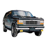
Ford Ranger Maintaince And Repair Manual (1119 pages)
Table Of Contents |
Troubleshooting |
Brand:
Ford |
Category:
Automobile |
Size: 60.2 MB

Ford Ranger Owner’s Manual (439 pages)
Diesel Particulate Filter
Brand:
Ford |
Category:
Automobile |
Size: 8.69 MB

Ford RANGER Owner’s Manual (227 pages)
Brand:
Ford |
Category:
Automobile |
Size: 7.3 MB

Ford Ranger Owner’s Handbook Manual (156 pages)
General Information
Brand:
Ford |
Category:
Automobile |
Size: 8.88 MB

Ford Ranger User Manual (13 pages)
Kids ride-on
Battery Charging Safety
Music Button
Remote Control
Troubleshooting
Specifications
Brand:
Ford |
Category:
Toy |
Size: 0.85 MB
Ford Ranger Service Manual (3 pages)
2011 — 1999 yrs.
Brand:
Ford |
Category:
Automobile |
Size: 0.58 MB
Summit FORD RANGER, MAZDA PICKUP SUM-7888300 Installation Instructions Manual (9 pages)
Summit automobile user manual
Manual is suitable for 3 more products:
1998 FORD RANGER1999 FORD RANGER2000 FORD RANGER
Brand:
Summit |
Category:
Automobile Accessories |
Size: 0.36 MB

Autoaccess FORCE PRO+ FORD RANGER 2019 CLOSED Installation Manual (11 pages)
Manual is suitable for 1 more product:
FORCE PRO+ FORD RANGER 2019 FOLD UP PANELS
Brand:
Autoaccess |
Category:
Automobile Accessories |
Size: 1.97 MB

Ford 2006 Ranger Owner’s Manual (280 pages)
Ford 2006 ford ranger owner’s guide
Maintenance Product Specifications and Capacities
Index
Manual is suitable for 1 more product:
Ranger 2007
Brand:
Ford |
Category:
Automobile |
Size: 3.04 MB
We have 203 Ford
Ranger manuals
covering a total of 90 years of production.
In the table below you can see 5
Ranger Workshop Manuals,1
Ranger Owners Manuals and 19 Miscellaneous
Ford Ranger downloads.
Our most popular manual is the
Ford — Ranger — Workshop Manual — 1983 — 2011
.
This (like all of our manuals) is available to download for free in PDF format.
How to download a Ford Ranger
Repair Manual (for any year)
These Ranger manuals have been provided by our users,
so we can’t guarantee completeness. We’ve checked the years that the manuals cover
and we have Ford Ranger repair manuals
for the following years; 1927, 1978, 1983, 1984, 1985, 1985, 1986, 1988, 1989, 1990, 1991, 1993, 1994, 1995, 1996, 1997, 1998, 1999, 2000, 2001, 2002, 2003, 2004, 2005, 2006, 2007, 2008, 2009, 2010, 2011, 2012, 2013, 2014, 2015, 2016 and 2017.
Go through the 203 different PDF’s that are displayed below,
for example this one. You’ll then be shown the first 10 pages of this specific
document, you can then scroll down and click ‘show full PDF’. Then you can click
download you’ve got a totally free car manual, forever!
What topics does the Ford Ranger
Service/Repair Manual cover?
In total, that’s over 330479 pages of content dedicated to your
Ford Ranger. Here’s a non exhaustive list
of what’s covered;
- Ford Ranger service manual for roadside repairs
- Ford Ranger owners manual covering weekly checks
- Ford Ranger workshop manual covering Lubricants, fluids and tyre pressures
- Ford Ranger service PDF’s covering routine maintenance and servicing
- Detailed Ford Ranger Engine and Associated Service Systems (for Repairs and Overhaul) (PDF)
- Ford Ranger Transmission data Service Manual PDF
- Ford Ranger Brakes and suspension PDF
- Ford Ranger Wiring Diagrams
Looking for a Free Ford Ranger Haynes /
Ford Ranger Chilton Manuals?
We get a lot of people coming to the site looking to get themselves a free
Ford Ranger Haynes
manual. There are two things you need to know; firstly it’s illegal, and secondly —
there are much better ways of servicing and understanding your
Ford Ranger engine than
the Haynes manual. That’s essentially what we’re here for — to give you an
alternative to the Haynes and Chilton, online and totally for free.
|
Ford RangerЭлектронные книги Ford Ranger для автомобилистов бесплатно
Руководство по ремонту, эксплуатации и техническому обслуживанию Ford Ranger СКАЧАТЬ 291 Мб Руководство по ремонту Ford Ranger в фотографиях СКАЧАТЬ 128 Mб Секреты ремонта Ford Ranger СКАЧАТЬ 132 Мб Подробная схема электрооборудования Ford Ranger СКАЧАТЬ 88 Мб Каталог деталей Ford Ranger СКАЧАТЬ 36 Мб Руководство по ремонту двигателя Ford Ranger СКАЧАТЬ 53 Мб Руководство по ремонту трансмиссии Ford Ranger СКАЧАТЬ 154 Мб Коды неисправностей Ford Ranger СКАЧАТЬ 50 Мб Мультимедийное Руководство по тюнингу Ford Ranger СКАЧАТЬ 51 Мб Руководства по ремонту Ford Ranger
Во избежание выхода из строя нейтрализатора не производите |