- Manuals
- Brands
- Kubota Manuals
- Lawn Mower
- V2203-M
Manuals and User Guides for Kubota V2203-M. We have 2 Kubota V2203-M manuals available for free PDF download: Workshop Manual, Safety & Operation Manual
Kubota V2203-M Workshop Manual (182 pages)
WSM
03-M-E3B SERIES,
03-M-DI-E3B SERIES,
03-M-E3BG SERIES
Brand: Kubota
|
Category: Engine
|
Size: 3.06 MB
Table of Contents
-
Before Servicing and Repairing
3
-
Safety First
3
-
Specifications
7
-
Dimensions
18
-
Wiring Diagram
24
-
Table of Contents
25
-
1 Engine Identification
26
-
Model Name and Engine Serial Number
26
-
Month of Manufacture
27
-
E3B Engine
28
-
Cylinder Number
28
-
-
2 General Precautions
29
-
3 Maintenance Check List
30
-
4 Check and Maintenance
33
-
Daily Check Points
33
-
Checking Engine Oil Level
33
-
Checking and Replenish Coolant
34
-
-
Check Points of Initial 50 Hours
35
-
Changing Engine Oil
35
-
Replacing Oil Filter Cartridge
36
-
-
Check Points of Every 50 Hours
37
-
Checking Fuel Hoses and Clamp Bands
37
-
Check Points of Every 100 Hours
38
-
Cleaning Air Cleaner Element
38
-
Cleaning Fuel Filter
38
-
Checking Battery Electrolyte Level
38
-
Fan Belt Damage and Wear
39
-
-
Check Points of Every 150 Hours
40
-
Changing Engine Oil for 90 MM Depth Oil Pan
40
-
Replacing Oil Filter Cartridge for 90 MM Depth Oil Pan
41
-
-
Check Points of Every 200 Hours
42
-
Changing Engine Oil for 124 MM Depth Oil Pan
42
-
Replacing Oil Filter Cartridge for 124 MM Depth Oil Pan
44
-
Checking Radiator Hoses and Clamp Bands
44
-
Checking Intake Air Line
45
-
-
Check Points of Every 400 Hours
46
-
Replacing Fuel Filter Cartridge
47
-
Replacing Fuel Filter Element
47
-
-
Check Points of Every 500 Hours
48
-
Cleaning Water Jacket and Radiator Interior
48
-
Anti-Freeze
49
-
Replacing Fan Belt
49
-
-
Check Points of Every 1 or 2 Months
50
-
Recharging
50
-
Precaution for Operating a Quick Charger
50
-
-
Check Points of Every Year
51
-
Battery Specific Gravity
51
-
Replacing Air Cleaner Element
51
-
-
Check Points of Every 800 Hours
52
-
Valve Clearance
52
-
Check Points of Every 1500 Hours
53
-
Nozzle Spraying Condition
53
-
Fuel Injection Pressure
54
-
Valve Seat Tightness
55
-
Nozzle Holder
55
-
-
Check Points of Every 3000 Hours
56
-
Checking Turbocharger
56
-
Checking Injection Pump
57
-
-
Check Points of Every 2 Years
59
-
Replacing Intake Air Line
59
-
Replacing Battery
59
-
Replacing Radiator Hoses and Clamp Bands
59
-
Replacing Fuel Hoses and Clamp Bands
60
-
Changing Radiator Coolant
61
-
-
-
5 Special Tools
63
-
Diesel Engine Compression Tester
63
-
Oil Pressure Tester
63
-
Injection Pump Pressure Tester
64
-
Valve Guide Replacing Tool
64
-
Bushing Replacing Tools
65
-
Crankshaft Bearing 1 Replacing Tool
65
-
Flywheel Stopper
65
-
Auxiliary Socket for Fixing Crankshaft Sleeve
66
-
Socket Wrench for Crank Pulley Nut
66
-
Balancer Metal Replacing Tool
68
-
Idle Gear 2 Puller
70
-
Mechanism
71
-
Engine Body
72
-
Piston
72
-
Built-In Dynamic Balancer (Balancer Model Only
73
-
Half-Floating Head Cover
74
-
Bottom Bypass System
75
-
Cooling System
75
-
Fuel System
76
-
Governor
76
-
Boost Compensator
77
-
Turbocharger System
77
-
Servicing
78
-
Clean or Replace
79
-
Engine Body
79
-
Troubleshooting
79
-
Adjust S-27
80
-
Repair or Replace S-29
80
-
Replace
80
-
Use Specified Fuel 5 to
80
-
Electronic Governor
83
-
Servicing Specifications
85
-
Timing Gear
88
-
Tightening Torques for General Use Screws, Bolts and Nuts
97
-
Tightening Torques for Special Use Screws, Bolts and Nuts
98
-
Checking and Adjusting
99
-
Checking, Disassembling and Servicing
99
-
Compression Pressure
99
-
Engine Body
99
-
Adjust
102
-
Cooling System
102
-
Engine Oil Pressure
102
-
Fan Belt Tension
102
-
-
Lubricating System
102
-
Radiator Cap Air Leakage
103
-
Radiator Water Leakage
103
-
Thermostat Valve Opening Temperature
104
-
-
Fuel System
105
-
Injection Timing
105
-
Fuel Tightness of Pump Element
107
-
Fuel Tightness of Delivery Valve
109
-
Battery Voltage
114
-
-
Electrical System
114
-
Magnet Switch Continuity Test
116
-
Magnetic Switch Test
116
-
Motor Test
116
-
Alternator on Unit Test
117
-
Glow Plug Continuity
117
-
Glow Plug Lead Terminal Voltage
117
-
Compressor Side
118
-
Engine Stop Solenoid
118
-
Radial Clearance
118
-
Turbine Side
118
-
-
Turbocharger
118
-
Electronic Governor
119
-
Speed Sensor
119
-
Water Temperature Sensor
119
-
Oil Pressure Switch
120
-
Solenoid
121
-
Alternator
122
-
Glow Plug Harness
122
-
Speed Switch
122
-
Battery
123
-
Emergency Stop Switch
123
-
Slow down Switch
123
-
Air Cleaner, Muffler and Others
124
-
-
Disassembling and Assembling
124
-
Draining Oil and Coolant
124
-
External Components
124
-
Turbocharger
125
-
Cylinder Head and Valves
126
-
Injection Pipes
126
-
Nozzle Holder Assembly and Glow Plug
127
-
Nozzle Heat Seal Service Removal Procedure
128
-
Rocker Arm and Push Rod
128
-
Cylinder Head
129
-
Tappets
130
-
Thermostat Assembly
131
-
Valves
131
-
Water Pump Assembly
131
-
-
Gear Case and Timing Gears
132
-
Injection Pump
132
-
Governor Springs and Speed Control Plate
134
-
Fan Drive Pulley
136
-
Idle Gear 2 and Hydraulic Pump Base Assembly
137
-
Crankshaft Oil Slinger
138
-
Gear Case
138
-
Idle Gear
138
-
Camshaft and Balancer Shaft
139
-
Crank Gear
140
-
Fuel Camshaft and Fork Lever Assembly
140
-
Oil Pump
140
-
Oil Pan and Oil Strainer
141
-
-
Piston and Connecting Rod
141
-
Pistons
142
-
Piston Ring and Connecting Rod
144
-
Bearing Case Cover
146
-
-
Flywheel and Crankshaft
146
-
Main Bearing Case Assembly
148
-
Starter
149
-
Alternator
150
-
Cylinder Head and Valves
151
-
Servicing
151
-
Top Clearance
151
-
Cylinder Head Flaw
152
-
Cylinder Head Surface Flatness
152
-
Valve Recessing
153
-
Clearance between Valve Stem and Valve Guide
154
-
Replacing Valve Guide
154
-
Valve Seating
155
-
Correcting Valve and Valve Seat
156
-
Free Length and Tilt of Valve Spring
157
-
Valve Lapping
157
-
Valve Spring Setting Load
157
-
Oil Clearance between Rocker Arm and Rocker Arm Shaft
158
-
Oil Clearance between Tappet and Tappet Guide Bore
158
-
Push Rod Alignment
158
-
Idle Gear Side Clearance
159
-
Timing Gear Backlash
159
-
Camshaft Alignment
160
-
Camshaft Side Clearance
160
-
Cam Height
161
-
Oil Clearance of Camshaft Journal
162
-
Balancer Shaft Alignment
163
-
Balancer Shaft Side Clearance
163
-
Oil Clearance between Idle Gear Shaft and Idle Gear Bushing
163
-
Replacing Idle Gear Bushing
163
-
Oil Clearance of Balancer Shaft Journal
164
-
-
Piston and Connecting Rod
164
-
Piston Pin Bore I.D.
164
-
Connecting Rod Alignment
165
-
Oil Clearance between Piston Pin and Small End Bushing
165
-
Replacing Connecting Rod Small End Bushing
165
-
Piston Ring Gap
166
-
Clearance between Piston Ring and Groove
167
-
Crankshaft Alignment
168
-
Side Clearance of Crankshaft
168
-
Oil Clearance between Crankpin and Crankpin Bearing
169
-
Oil Clearance between Crankshaft Journal and Crankshaft Bearing
170
-
Replacing Crankshaft Bearing
170
-
Replacing Crankshaft Sleeve
172
-
Cylinder Wear
173
-
Correcting Cylinder
174
-
Clearance between Rotor and Cover
175
-
-
Oil Pump
175
-
Overrunning Clutch
175
-
Rotor Lobe Clearance
175
-
-
Starter
175
-
Commutator and Mica
176
-
Brush Wear
177
-
Armature Coil
178
-
Brush Holder
178
-
Field Coil
178
-
-
Alternator
179
-
Bearing
179
-
Rotor
179
-
Slip Ring
179
-
-
Stator
179
-
IC Regulator
180
-
Rectifier
180
-
-
Advertisement

Kubota V2203-M Safety & Operation Manual (58 pages)
R-311 Rotary Mower with folding ROPS
Brand: Kubota
|
Category: Lawn Mower
|
Size: 2.66 MB
Table of Contents
-
English
2
-
Table of Contents
2
-
1 Safety
3
-
Operating Safety
3
-
Important Safety Notes
4
-
-
2 Decals
5
-
3 Controls
9
-
Icons
9
-
Control Descriptions
11
-
Control Panel Levers
11
-
Control Panel Switches
12
-
Gauges and Circuit Breakers
12
-
Warning Lights
13
-
-
4 Operation
15
-
Daily Inspection
15
-
Interlock System
15
-
Operating Procedures
16
-
Starting
17
-
Stopping / Parking
17
-
To Drive / Transport
18
-
Transport Latches
18
-
Hillside Operation
18
-
Mowing
19
-
4.10 Towing / Trailering
19
-
4.11 Folding Rops
19
-
4.12 Daily Maintenance
20
-
-
5 Quality of Cut
21
-
Quality of Cut Troubleshooting
21
-
Washboarding
21
-
Step Cutting
22
-
Scalping
23
-
Stragglers
24
-
Streaks
25
-
Windrowing
26
-
Mismatched Cutting Units
27
-
-
6 Notes
28
-
-
Suomi
30
-
Contents 2
30
-
1 Turvallisuus
31
-
Käyttöturvallisuus
31
-
Tärkeitä Huomautuksia
32
-
-
2 Merkinnät
33
-
Merkinnät
36
-
-
3 SÄÄTIMET Kuvakkeet
37
-
Ohjainten Kuvaus
39
-
Ohjauspaneelin Vivut
39
-
Ohjauspaneelin Kytkimet
40
-
Mittarit Ja Suojakatkaisimet
40
-
Varoitusvalot
41
-
-
4 Käyttö
43
-
4.1 Päivittäinen Tarkastus
43
-
Lukitusjärjestelmä
43
-
Ohjaustoimet
44
-
Käynnistäminen
45
-
Pysäyttäminen Ja Pysäköiminen
45
-
Ajaminen Ja Kuljettaminen
46
-
Kuljetussalvat
46
-
Rinnekäyttö
46
-
Leikkaaminen
47
-
4.10 Hinaaminen Ja Vetäminen
47
-
4.11 Taittuva Rops
47
-
4.12 Päivittäinen Huolto
48
-
-
5 Leikkuujälki
49
-
Leikkuujäljen Vianetsintä
49
-
Pyykkilautakuvio
49
-
Porrasmainen Leikkaus
50
-
Paljaat Kohdat
51
-
Repsotus
52
-
Raidat
53
-
Kasautuminen
54
-
Leikkuriyksiköiden Epätasapaino
55
-
-
Advertisement
Related Products
-
Kubota V2203-M EC
-
Kubota V2203-M-E3
-
Kubota V2203-M-E3BG
-
Kubota V2203-M-DI
-
Kubota V2203-M-E
-
Kubota V2203-B
-
Kubota V2203BE
-
Kubota V2203-M-BG
-
Kubota V2003-M-E3
-
Kubota V2403-M-T-E3
Kubota Categories
Tractor
![]()
Lawn Mower
Engine
Excavators
Farm Equipment
More Kubota Manuals
Содержание
- Manual_Kubota_V2203
- Short Description
- Description
Manual_Kubota_V2203
Short Description
Description
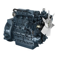
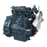
DIESEL ENGINE 03-M-E3B SERIES, 03-M-DI-E3B SERIES, 03-M-E3BG SERIES
KiSC issued 07, 2008 A
TO THE READER This Workshop Manual has been prepared to provide servicing personnel with information on the mechanism, service and maintenance of 03-M-E3B, 03-M-DI-E3B and 03-M-E3BG series. It is divided into three parts, “General”, “Mechanism” and “Servicing”. Q General Information on the engine identification, the general precautions, maintenance check list, check and maintenance and special tools are described. Q Mechanism Information on the construction and function are included. This part should be understood before proceeding with troubleshooting, disassembling and servicing. Refer to Diesel Engine Mechanism Workshop Manual (Code No. 9Y021-01875) for the one which has not been described to this workshop manual. Q Servicing Information on the troubleshooting, servicing specification lists, tightening torque, checking and adjusting, disassembling and assembling, and servicing which cover procedures, precautions, factory specifications and allowable limits. All information illustrations and specifications contained in this manual are based on the latest product information available at the time of publication. The right is reserved to make changes in all information at any time without notice. Due to covering many models of this manual, information or picture being used, have not been specified as one model. March 2007 © KUBOTA Corporation 2007
KiSC issued 07, 2008 A
03-M-E3B, 03-M-DI-E3B, 03-M-E3BG WSM SAFETY INSTRUCTIONS
SAFETY FIRST This symbol, the industry’s “Safety Alert Symbol”, is used throughout this manual and on labels on the machine itself to warn of the possibility of personal injury. Read these instructions carefully. It is essential that you read the instructions and safety regulations before you attempt to repair or use this unit.
: Indicates an imminently hazardous situation which, if not avoided, will result in death or serious injury.
: Indicates a potentially hazardous situation which, if not avoided, could result in death or serious injury.
: Indicates a potentially hazardous situation which, if not avoided, may result in minor or moderate injury.
: Indicates that equipment or property damage could result if instructions are not followed.
: Gives helpful information.
BEFORE SERVICING AND REPAIRING • Read all instructions and safety instructions in this manual and on your engine safety decals. • Clean the work area and engine. • Park the machine on a firm and level ground. • Allow the engine to cool before proceeding. • Stop the engine, and remove the key. • Disconnect the battery negative cable. • Hang a “DO NOT OPERATE” tag in operator station.
KiSC issued 07, 2008 A
03-M-E3B, 03-M-DI-E3B, 03-M-E3BG WSM
SAFETY STARTING • Do not start the engine by shorting across starter terminals or bypassing the safety start switch. • Unauthorized modifications to the engine may impair the function and / or safety and affect engine life.
SAFETY WORKING • Do not work on the machine while under the influence of alcohol, medication, or other substances or while fatigued. • Wear close fitting clothing and safety equipment appropriate to the job. • Use tools appropriate to the work. Makeshift tools, parts, and procedures are not recommended. • When servicing is performed together by two or more persons, take care to perform all work safely. • Do not touch the rotating or hot parts while the engine is running. • Never remove the radiator cap while the engine is running, or immediately after stopping. Otherwise, hot water will spout out from radiator. Only remove radiator cap when cool enough to touch with bare hands. Slowly loosen the cap to first stop to relieve pressure before removing completely. • Escaping fluid (fuel or hydraulic oil) under pressure can penetrate the skin causing serious injury. Relieve pressure before disconnecting hydraulic or fuel lines. Tighten all connections before applying pressure. • Wear a suitable hearing protective device such as earmuffs or earplugs to protect against objectionable or uncomfortable loud noises. • Do not open high-pressure fuel system. High-pressure fluid remaining in fuel lines can cause serious injury. Do not disconnect or attempt to repair fuel lines, sensors, or any other components between the high-pressure fuel pump and injectors on engines with high pressure common rail fuel system. • High voltage exceeding 100 V is generated in the ECU, and is applied to the injector. Pay sufficient caution to electric shock when performing work activities.
KiSC issued 07, 2008 A
03-M-E3B, 03-M-DI-E3B, 03-M-E3BG WSM
AVOID FIRES • Fuel is extremely flammable and explosive under certain conditions. Do not smoke or allow flames or sparks in your working area. • To avoid sparks from an accidental short circuit, always disconnect the battery negative cable first and connect it last. • Battery gas can explode. Keep sparks and open flame away from the top of battery, especially when charging the battery. • Make sure that no fuel has been spilled on the engine.
VENTILATE WORK AREA • If the engine must be running to do some work, make sure the area is well ventilated. Never run the engine in a closed area. The exhaust gas contains poisonous carbon monoxide.
PREVENT ACID BURNS • Sulfuric acid in battery electrolyte is poisonous. It is strong enough to burn skin, clothing and cause blindness if splashed into eyes. Keep electrolyte away from eyes, hands and clothing. If you spill electrolyte on yourself, flush with water, and get medical attention immediately.
DISPOSE OF FLUIDS PROPERLY • Do not pour fluids into the ground, down a drain, or into a stream, pond, or lake. Observe relevant environmental protection regulations when disposing of oil, fuel, coolant, electrolyte and other harmful waste.
KiSC issued 07, 2008 A
03-M-E3B, 03-M-DI-E3B, 03-M-E3BG WSM
PREPARE FOR EMERGENCIES • Keep a first aid kit and fire extinguisher handy at all times. • Keep emergency numbers for doctors, ambulance service, hospital and fire department near your telephone.
KiSC issued 07, 2008 A
03-M-E3B, 03-M-DI-E3B, 03-M-E3BG WSM
Number of Cylinders
Vertical, Water-cooled, 4 cycle diesel engine
83.0 X 92.4 mm (3.27 X 3.64 in.)
87.0 X 92.4 mm (3.43 X 3.64 in.) 1647 cm3 (100.5 cu.in.)
ISO Net Continuous
19.5 KW / 2800 min-1 (rpm) (26.1 HP / 2800 min-1 (rpm))
21.2 KW / 2800 min-1 (rpm) (28.4 HP / 2800 min-1 (rpm))
ISO/SAE Net Intermittent
22.4 KW / 2800 min-1 (rpm) (30.0 HP / 2800 min-1 (rpm))
24.4 KW / 2800 min-1 (rpm) (32.7 HP / 2800 min-1 (rpm))
SAE Gross Intermittent
23.8 KW / 2800 min-1 (rpm) (31.9 HP / 2800min-1 (rpm))
26.1 KW / 2800 min-1 (rpm) (35.0 HP / 2800 min-1 (rpm)) 3020 min-1 (rpm)
Maximum Bare Speed
750 to 850 min-1 (rpm)
Minimum Bare Idling Speed Combustion Chamber
Spherical Type (E-TVCS)
Fuel Injection Pump
PFR 3M Type Mini Pump (DENSO)
Mechanical all speed governor
Direction of Rotation
Counter-clockwise (viewd from flywheel side)
OPD Mini Nozzle (DENSO) 0.2662 rad (15.25 °) before T.D.C.
Injection Timing Firing Order
0.2836 rad (16.25 °) before T.D.C. 1-2-3
13.73 MPa (140.0 kgf/cm2, 1991 psi)
Injection Pressure Compression Ratio
22.0 : 1 Forced Lubrication by Trochoid Pump
Oil Pressure Indicating
Electrical type switch
Full flow paper filter (cartridge type)
Pressurized radiator, forced circulation with water pump
Electric Starting with Starter
Starting Support Device
By glow plug in combustion chamber
12 V, 60 AH equivalent
Diesel Fuel No.2-D (ASTM D975)
Lubricating Oil Lubricating Oil Capacity
Class CF lubricating oil as per API classification is recommended. For details on recommended lubricating oils, see page G-7, 10 Oil Pan Depth 90 mm (3.5 in.)
Oil Pan Depth 124 mm (4.88 in.)
* The specification described above is of the standard engine of each model. * Conversion Formula : HP = 0.746 kW, PS = 0.7355 kW W10275180
KiSC issued 07, 2008 A
03-M-E3B, 03-M-DI-E3B, 03-M-E3BG WSM
Number of Cylinders Type
3 Vertical, Water-cooled, 4 cycle diesel engine
87.0 X 102.4 mm (3.43 X 4.031 in.)
1826 cm3 (111.4 cu.in.)
ISO Net Continuous
22.8 KW / 2700 min-1 (rpm) (30.6 HP / 2700 min-1 (rpm))
ISO/SAE Net Intermittent
26.3 KW / 2700 min-1 (rpm) (35.3 HP / 2700 min-1 (rpm))
SAE Gross Intermittent
27.9 KW / 2700 min-1 (rpm) (37.4 HP / 2700 min-1 (rpm))
Maximum Bare Speed
3020 min-1 (rpm) 750 to 850 min-1 (rpm)
Minimum Bare Idling Speed Combustion Chamber
Spherical Type (E-TVCS)
Fuel Injection Pump
PFR 3M Type Mini Pump (DENSO)
Mechanical all speed governor
Direction of Rotation
Counter-clockwise (viewd from flywheel side)
OPD Mini Nozzle (DENSO)
0.2836 rad (16.25 °) before T.D.C.
1-2-3 13.73 MPa (140.0 kgf/cm2, 1991 psi)
Injection Pressure Compression Ratio
Forced Lubrication by Trochoid Pump
Oil Pressure Indicating
Electrical type switch
Full flow paper filter (cartridge type)
Pressurized radiator, forced circulation with water pump
Electric Starting with Starter
Starting Support Device
By glow plug in combustion chamber
12 V, 92 AH equivalent
Diesel Fuel No.2-D (ASTM D975)
Lubricating Oil Lubricating Oil Capacity
Class CF lubricating oil as per API classification is recommended. For details on recommended lubricating oils, see page G-7, 10 Oil Pan Depth 90 mm (3.5 in.)
Oil Pan Depth 124 mm (4.88 in.)
* The specification described above is of the standard engine of each model. * Conversion Formula : HP = 0.746 kW, PS = 0.7355 kW W10316200
KiSC issued 07, 2008 A
03-M-E3B, 03-M-DI-E3B, 03-M-E3BG WSM
Number of Cylinders
Vertical, Water-cooled, 4 cycle diesel engine
83.0 X 92.4 mm (3.27 X 3.64 in.)
87.0 X 92.4 mm (3.43 X 3.64 in.)
2197 cm3 (134.1 cu.in.)
1999 cm (122.0 cu.in.) min-1
ISO Net Continuous
26.7 KW / 2800 (rpm) (35.8 HP / 2800 min-1 (rpm))
29.6 KW / 2800 min-1 (rpm) (39.7 HP / 2800 min-1 (rpm))
ISO/SAE Net Intermittent
30.8 KW / 2800 min-1 (rpm) (41.3 HP / 2800 min-1 (rpm))
34.1 KW / 2800 min-1 (rpm) (45.7 HP / 2800 min-1 (rpm))
SAE Gross Intermittent
32.6 KW / 2800 min-1 (rpm) (43.7 HP / 2800 min-1 (rpm))
35.9 KW / 2800 min-1 (rpm) (48.1 HP / 2800 min-1 (rpm)) 3020 min-1 (rpm)
Maximum Bare Speed
750 to 850 min-1 (rpm)
Minimum Bare Idling Speed Combustion Chamber
Spherical Type (E-TVCS)
Fuel Injection Pump
PFR 4M Type Mini Pump (DENSO)
Mechanical all speed governor
Direction of Rotation
Counter-clockwise (viewd from flywheel side)
OPD Mini Nozzle (DENSO)
0.2836 rad (16.25 °) before T.D.C.
1-3-4-2 13.73 MPa (140.0 kgf/cm2, 1991 psi)
Injection Pressure Compression Ratio
22.0 : 1 Forced Lubrication by Trochoid Pump
Oil Pressure Indicating
Electrical type switch
Full flow paper filter (cartridge type)
Pressurized radiator, forced circulation with water pump
Electric Starting with Starter
Starting Support Device
By glow plug in combustion chamber
12 V, 88 AH equivalent
Diesel Fuel No.2-D (ASTM D975)
Lubricating Oil Lubricating Oil Capacity
Class CF lubricating oil as per API classification is recommended. For details on recommended lubricating oils, see page G-7, 10 Oil Pan Depth 90 mm (3.5 in.)
Oil Pan Depth 124 mm (4.88 in.)
* The specification described above is of the standard engine of each model. * Conversion Formula : HP = 0.746 kW, PS = 0.7355 kW W10384770
KiSC issued 07, 2008 A
03-M-E3B, 03-M-DI-E3B, 03-M-E3BG WSM
Number of Cylinders Type
4 Vertical, Water-cooled, 4 cycle diesel engine
87.0 X 102.4 mm (3.43 X 4.031 in.) 2434 cm3 (148.5 cu.in.)
Total Displacement ISO Net Continuous
30.2 KW / 2700 (rpm) (40.5 HP / 2700 min-1 (rpm))
36.4 KW / 2700 min-1 (rpm) (48.8 HP / 2700 min-1 (rpm))
ISO/SAE Net Intermittent
34.8 KW / 2700 min-1 (rpm) (46.7 HP / 2700 min-1 (rpm))
41.9 KW / 2700 min-1 (rpm) (56.2 HP / 2700 min-1 (rpm))
SAE Gross Intermittent
36.5 KW / 2700 min-1 (rpm) (48.9 HP / 2700 min-1 (rpm))
44.0 KW / 2700 min-1 (rpm) (59.0 HP / 2700 min-1 (rpm))
Maximum Bare Speed
Minimum Bare Idling Speed
750 to 850 min (rpm)
Spherical Type (E-TVCS)
Fuel Injection Pump
PFR 4M Type Mini Pump (DENSO)
Mechanical all speed governor
Direction of Rotation
Counter-clockwise (viewd from flywheel side)
OPD Mini Nozzle (DENSO) 0.2836 rad (16.25 °) before T.D.C.
Injection Timing Firing Order
0.14 rad (8.3 °) before T.D.C. 1-3-4-2
13.73 MPa (140.0 kgf/cm2, 1991 psi)
Injection Pressure Compression Ratio
23.0 : 1 Forced Lubrication by Trochoid Pump
Oil Pressure Indicating
Electrical type switch
Full flow paper filter (cartridge type)
Pressurized radiator, forced circulation with water pump
Electric Starting with Starter
Starting Support Device
By glow plug in combustion chamber
12 V, 92 AH equivalent
Diesel Fuel No.2-D (ASTM D975)
Lubricating Oil Lubricating Oil Capacity
Class CF lubricating oil as per API classification is recommended. For details on recommended lubricating oils, see page G-7, 10 Oil Pan Depth 90 mm (3.5 in.)
Oil Pan Depth 124 mm (4.88 in.) Weight (Dry)
* The specification described above is of the standard engine of each model. * Conversion Formula : HP = 0.746 kW, PS = 0.7355 kW W10334350
KiSC issued 07, 2008 A
03-M-E3B, 03-M-DI-E3B, 03-M-E3BG WSM
Number of Cylinders Type
3 Vertical, Water-cooled, 4 cycle diesel engine
87.0 X 102.4 mm (3.43 X 4.031 in.)
1826 cm3 (111.4 cu.in.)
ISO Net Continuous
23.2 KW / 2700 min-1 (rpm) (31.1 HP / 2700 min-1 (rpm))
ISO/SAE Net Intermittent
26.7 KW / 2700 min-1 (rpm) (35.8 HP / 2700 min-1 (rpm))
SAE Gross Intermittent
27.9 KW / 2700 min-1 (rpm) (37.4 HP / 2700 min-1 (rpm))
Maximum Bare Speed
2920 min-1 (rpm) 850 to 950 min-1 (rpm)
Minimum Bare Idling Speed Combustion Chamber
Reentrant Type (Direct Injection)
Fuel Injection Pump
Bosch “K” Type Mini Pump
Mechanical all speed governor
Direction of Rotation
Counter-clockwise (viewd from flywheel side)
Bosch “P” Type Hole Nozzle
0.087 rad (5.0 °) before T.D.C.
Firing Order Injection Pressure
18.63 MPa (190.0 kgf/cm2, 2702 psi)
22.56 MPa (230.0 kgf/cm2, 3271 psi)
Forced Lubrication by Trochoid Pump
Oil Pressure Indicating
Electrical type switch
Full flow paper filter (cartridge type)
Pressurized radiator, forced circulation with water pump
Electric Starting with Starter
Starting Support Device
By glow plug in combustion chamber
12 V, 88 AH equivalent
Diesel Fuel No.2-D (ASTM D975)
Lubricating Oil Lubricating Oil Capacity
Class CF lubricating oil as per API classification is recommended. For details on recommended lubricating oils, see page G-7, 10 Oil Pan Depth 90 mm (3.5 in.)
Oil Pan Depth 124 mm (4.88 in.)
* The specification described above is of the standard engine of each model. * Conversion Formula : HP = 0.746 kW, PS = 0.7355 kW W10343470
KiSC issued 07, 2008 A
03-M-E3B, 03-M-DI-E3B, 03-M-E3BG WSM
Number of Cylinders Type
4 Vertical, Water-cooled, 4 cycle diesel engine
87.0 X 102.4 mm (3.43 X 4.031 in.) 2434 cm3 (148.5 cu.in.)
Total Displacement ISO Net Continuous
30.5 KW / 2700 (rpm) (40.9 HP / 2700 min-1 (rpm))
30.7 KW / 2400 min-1 (rpm) (41.2 HP / 2400 min-1 (rpm))
ISO/SAE Net Intermittent
35.1 KW / 2700 min-1 (rpm) (47.1 HP / 2700 min-1 (rpm))
35.3 KW / 2400 min-1 (rpm) (47.3 HP / 2400 min-1 (rpm))
SAE Gross Intermittent
36.5 KW / 2700 min-1 (rpm) (48.9 HP / 2700 min-1 (rpm))
36.5 KW / 2400 min-1 (rpm) (48.9 HP / 2400 min-1 (rpm))
Maximum Bare Speed
Minimum Bare Idling Speed
Reentrant Type (Direct Injection)
Fuel Injection Pump
Bosch “K” Type Mini Pump
Mechanical all speed governor
Direction of Rotation
Counter-clockwise (viewd from flywheel side)
Bosch “P” Type Hole Nozzle 0.087 rad (5.0 °) before T.D.C.
Injection Timing Firing Order Injection Pressure
850 to 950 min (rpm)
0.096 rad (5.5 °) before T.D.C. 1-3-4-2
18.63 MPa (190.0 kgf/cm2, 2702 psi)
22.56 MPa (230.0 kgf/cm2, 3271 psi)
20.2 : 1 Forced Lubrication by Trochoid Pump
Oil Pressure Indicating
Electrical type switch
Full flow paper filter (cartridge type)
Pressurized radiator, forced circulation with water pump
Electric Starting with Starter
Starting Support Device
By glow plug in combustion chamber
12 V, 92 AH equivalent
Diesel Fuel No.2-D (ASTM D975)
Lubricating Oil Lubricating Oil Capacity
Class CF lubricating oil as per API classification is recommended. For details on recommended lubricating oils, see page G-7, 10 Oil Pan Depth 90 mm (3.5 in.)
Oil Pan Depth 124 mm (4.88 in.)
9.5 L (2.5 U.S.gals) 184 kg (406 lbs)
* The specification described above is of the standard engine of each model. * Conversion Formula : HP = 0.746 kW, PS = 0.7355 kW W10452650
KiSC issued 07, 2008 A
03-M-E3B, 03-M-DI-E3B, 03-M-E3BG WSM
Number of Cylinders Type
3 Vertical, Water-cooled, 4 cycle diesel engine
87.0 X 92.4 mm (3.43 X 3.64 in.) 1647 cm3 (100.5 cu.in.)
Total Displacement min-1
ISO Net Continuous
14.0 KW / 1500 (rpm) (18.8 HP / 1500 min-1 (rpm))
16.9 KW / 1800 min-1 (rpm) (22.7 HP / 1800 min-1 (rpm))
ISO/SAE Net Intermittent
16.1 KW / 1500 min-1 (rpm) (21.6 HP / 1500 min-1 (rpm))
19.5 KW / 1800 min-1 (rpm) (26.1 HP / 1800 min-1 (rpm))
SAE Gross Intermittent
16.6 KW / 1500 min-1 (rpm) (22.3 HP / 1500 min-1 (rpm))
20.2 KW / 1800 min-1 (rpm) (27.1 HP / 1800 min-1 (rpm))
Maximum Bare Speed
Minimum Bare Idling Speed
Spherical Type (E-TVCS)
Fuel Injection Pump
PFR 3M Type Mini Pump (DENSO)
Mechanical all speed governor + Electronic Governor
Direction of Rotation
Counter-clockwise (viewd from flywheel side)
OPD Mini Nozzle (DENSO)
0.2487 rad (14.25 °) before T.D.C.
1-2-3 13.73 MPa (140.0 kgf/cm2, 1991 psi)
Injection Pressure Compression Ratio
Forced Lubrication by Trochoid Pump
Oil Pressure Indicating
Electrical type switch
Full flow paper filter (cartridge type)
Pressurized radiator, forced circulation with water pump
Electric Starting with Starter
Starting Support Device
By glow plug in combustion chamber
12 V, 60 AH equivalent
Diesel Fuel No.2-D (ASTM D975)
Lubricating Oil Lubricating Oil Capacity
Class CF lubricating oil as per API classification is recommended. For details on recommended lubricating oils, see page G-7, 10 Oil Pan Depth 90 mm (3.5 in.)
Oil Pan Depth 124 mm (4.88 in.)
* The specification described above is of the standard engine of each model. * Conversion Formula : HP = 0.746 kW, PS = 0.7355 kW W10336120
KiSC issued 07, 2008 A
03-M-E3B, 03-M-DI-E3B, 03-M-E3BG WSM
Number of Cylinders Type
4 Vertical, Water-cooled, 4 cycle diesel engine
83.0 X 92.4 mm (3.27 X 3.64 in.) 1999 cm3 (122.0 cu.in.)
Total Displacement min-1
ISO Net Continuous
17.5 KW / 1500 (rpm) (23.5 HP / 1500 min-1 (rpm))
20.3 KW / 1800 min-1 (rpm) (27.2 HP / 1800 min-1 (rpm))
ISO/SAE Net Intermittent
20.1 KW / 1500 min-1 (rpm) (27.0 HP / 1500 min-1 (rpm))
23.4 KW / 1800 min-1 (rpm) (31.4 HP / 1800 min-1 (rpm))
SAE Gross Intermittent
20.6 KW / 1500 min-1 (rpm) (27.6 HP / 1500 min-1 (rpm))
24.3 KW / 1800 min-1 (rpm) (32.6 HP / 1800 min-1 (rpm))
Maximum Bare Speed
Minimum Bare Idling Speed
Spherical Type (E-TVCS)
Fuel Injection Pump
PFR 4M Type Mini Pump (DENSO)
Mechanical all speed governor + Electronic Governor
Direction of Rotation
Counter-clockwise (viewd from flywheel side)
OPD Mini Nozzle (DENSO)
0.2487 rad (14.25 °) before T.D.C.
1-3-4-2 13.73 MPa (140.0 kgf/cm2, 1991 psi)
Injection Pressure Compression Ratio
Forced Lubrication by Trochoid Pump
Oil Pressure Indicating
Electrical type switch
Full flow paper filter (cartridge type)
Pressurized radiator, forced circulation with water pump
Electric Starting with Starter
Starting Support Device
By glow plug in combustion chamber
12 V, 88 AH equivalent
Diesel Fuel No.2-D (ASTM D975)
Lubricating Oil Lubricating Oil Capacity
Class CF lubricating oil as per API classification is recommended. For details on recommended lubricating oils, see page G-7, 10 Oil Pan Depth 90 mm (3.5 in.)
Oil Pan Depth 124 mm (4.88 in.)
* The specification described above is of the standard engine of each model. * Conversion Formula : HP = 0.746 kW, PS = 0.7355 kW W10389960
KiSC issued 07, 2008 A
03-M-E3B, 03-M-DI-E3B, 03-M-E3BG WSM
Number of Cylinders Type
4 Vertical, Water-cooled, 4 cycle diesel engine
83.0 X 92.4 mm (3.27 X 3.64 in.) 1999 cm3 (122.0 cu.in.)
Total Displacement min-1
ISO Net Continuous
22.3 KW / 1500 (rpm) (29.9 HP / 1500 min-1 (rpm))
25.7 KW / 1800 min-1 (rpm) (34.5 HP / 1800 min-1 (rpm))
ISO/SAE Net Intermittent
25.7 KW / 1500 min-1 (rpm) (34.5 HP / 1500 min-1 (rpm))
29.6 KW / 1800 min-1 (rpm) (39.7 HP / 1800 min-1 (rpm))
SAE Gross Intermittent
26.2 KW / 1500 min-1 (rpm) (35.1 HP / 1500 min-1 (rpm))
30.6 KW / 1800 min-1 (rpm) (41.0 HP / 1800 min-1 (rpm))
Maximum Bare Speed
Minimum Bare Idling Speed
Spherical Type (E-TVCS)
Fuel Injection Pump
PFR 4M Type Mini Pump (DENSO)
Mechanical all speed governor + Electronic Governor
Direction of Rotation
Counter-clockwise (viewd from flywheel side)
OPD Mini Nozzle (DENSO)
0.2662 rad (15.25 °) before T.D.C.
1-3-4-2 13.73 MPa (140.0 kgf/cm2, 1991 psi)
Injection Pressure Compression Ratio
Forced Lubrication by Trochoid Pump
Oil Pressure Indicating
Electrical type switch
Full flow paper filter (cartridge type)
Pressurized radiator, forced circulation with water pump
Electric Starting with Starter
Starting Support Device
By glow plug in combustion chamber
12 V, 88 AH equivalent
Diesel Fuel No.2-D (ASTM D975)
Lubricating Oil Lubricating Oil Capacity
Class CF lubricating oil as per API classification is recommended. For details on recommended lubricating oils, see page G-7, 10 Oil Pan Depth 90 mm (3.5 in.)
Oil Pan Depth 124 mm (4.88 in.)
* The specification described above is of the standard engine of each model. * Conversion Formula : HP = 0.746 kW, PS = 0.7355 kW W10413710
KiSC issued 07, 2008 A
03-M-E3B, 03-M-DI-E3B, 03-M-E3BG WSM
Number of Cylinders Type
4 Vertical, Water-cooled, 4 cycle diesel engine
87.0 X 92.4 mm (3.43 X 3.64 in.) 2197 cm3 (134.1 cu.in.)
Total Displacement min-1
ISO Net Continuous
18.8 KW / 1500 (rpm) (25.2 HP / 1500 min-1 (rpm))
22.6 KW / 1800 min-1 (rpm) (30.3 HP / 1800 min-1 (rpm))
ISO/SAE Net Intermittent
21.7 KW / 1500 min-1 (rpm) (29.1 HP / 1500 min-1 (rpm))
26.0 KW / 1800 min-1 (rpm) (34.9 HP / 1800 min-1 (rpm))
SAE Gross Intermittent
22.2 KW / 1500 min-1 (rpm) (29.8 HP / 1500 min-1 (rpm))
26.9 KW / 1800 min-1 (rpm) (36.1 HP / 1800 min-1 (rpm))
Maximum Bare Speed
Minimum Bare Idling Speed
Spherical Type (E-TVCS)
Fuel Injection Pump
PFR 4M Type Mini Pump (DENSO)
Mechanical all speed governor + Electronic Governor
Direction of Rotation
Counter-clockwise (viewd from flywheel side)
OPD Mini Nozzle (DENSO)
0.2487 rad (14.25 °) before T.D.C.
1-3-4-2 13.73 MPa (140.0 kgf/cm2, 1991 psi)
Injection Pressure Compression Ratio
Forced Lubrication by Trochoid Pump
Oil Pressure Indicating
Electrical type switch
Full flow paper filter (cartridge type)
Pressurized radiator, forced circulation with water pump
Electric Starting with Starter
Starting Support Device
By glow plug in combustion chamber
12 V, 88 AH equivalent
Diesel Fuel No.2-D (ASTM D975)
Lubricating Oil Lubricating Oil Capacity
Class CF lubricating oil as per API classification is recommended. For details on recommended lubricating oils, see page G-7, 10 Oil Pan Depth 90 mm (3.5 in.)
Oil Pan Depth 124 mm (4.88 in.)
* The specification described above is of the standard engine of each model. * Conversion Formula : HP = 0.746 kW, PS = 0.7355 kW W10419300
KiSC issued 07, 2008 A
03-M-E3B, 03-M-DI-E3B, 03-M-E3BG WSM
Number of Cylinders Type
4 Vertical, Water-cooled, 4 cycle diesel engine
87.0 X 102.4 mm (3.43 X 4.031 in.) 2434 cm3 (148.5 cu.in.)
Total Displacement min-1
ISO Net Continuous
21.5 KW / 1500 (rpm) (28.8 HP / 1500 min-1 (rpm))
25.1 KW / 1800 min-1 (rpm) (33.7 HP / 1800 min-1 (rpm))
ISO/SAE Net Intermittent
24.8 KW / 1500 min-1 (rpm) (33.3 HP / 1500 min-1 (rpm))
28.9 KW / 1800 min-1 (rpm) (38.8 HP / 1800 min-1 (rpm))
SAE Gross Intermittent
25.3 KW / 1500 min-1 (rpm) (33.9 HP / 1500 min-1 (rpm))
29.8 KW / 1800 min-1 (rpm) (40.0 HP / 1800 min-1 (rpm))
Maximum Bare Speed
Minimum Bare Idling Speed
Spherical Type (E-TVCS)
Fuel Injection Pump
PFR 4M Type Mini Pump (DENSO)
Mechanical all speed governor + Electronic Governor
Direction of Rotation
Counter-clockwise (viewd from flywheel side)
OPD Mini Nozzle (DENSO)
0.2487 rad (14.25 °) before T.D.C.
1-3-4-2 13.73 MPa (140.0 kgf/cm2, 1991 psi)
Injection Pressure Compression Ratio
Forced Lubrication by Trochoid Pump
Oil Pressure Indicating
Electrical type switch
Full flow paper filter (cartridge type)
Pressurized radiator, forced circulation with water pump
Electric Starting with Starter
Starting Support Device
By glow plug in combustion chamber
12 V, 88 AH equivalent
Diesel Fuel No.2-D (ASTM D975)
Lubricating Oil Lubricating Oil Capacity
Class CF lubricating oil as per API classification is recommended. For details on recommended lubricating oils, see page G-7, 10 Oil Pan Depth 90 mm (3.5 in.)
Oil Pan Depth 124 mm (4.88 in.)
* The specification described above is of the standard engine of each model. * Conversion Formula : HP = 0.746 kW, PS = 0.7355 kW W10424850
- Manuals
- Brands
- Kubota Manuals
- Engine
- V2203-M-E
Manuals and User Guides for Kubota V2203-M-E. We have 2 Kubota V2203-M-E manuals available for free PDF download: Operator’s Manual

Kubota V2203-M-E Operator’s Manual (39 pages)
Brand: Kubota
|
Category: Engine
|
Size: 3.12 MB
Table of Contents
-
Table of Contents
2
-
Safe Operation
12
-
Servicing of the Engine
12
-
Names of Parts
13
-
Pre-Operation Check
14
-
Break-In
14
-
Daily Check
14
-
-
Operating the Engine
15
-
Starting the Engine(Normal)
15
-
Cold Weather Starting
16
-
Stopping the Engine
17
-
Checks During Operation
17
-
Radiator Cooling Water(Coolant)
17
-
Oil Pressure Lamp
17
-
Fuel
18
-
Color of Exhaust
18
-
Immediately Stop the Engine if
18
-
-
Reversed Engine Revolution and Remedies
18
-
How to Tell When the Engine Starts Running Backwards
18
-
Remedies
18
-
-
-
Maintenance
19
-
Service Intervals
20
-
-
Periodic Service
22
-
Fuel
22
-
Fuel Level Check and Refueling
22
-
Air Bleeding the Fuel System
23
-
Checking the Fuel Pipes
24
-
Cleaning the Fuel Filter Pot
24
-
Fuel Filter Cartridge Replacement
25
-
-
Engine Oil
25
-
Checking Oil Level and Adding Engine Oil
25
-
Changing Engine Oil
26
-
Replacing the Oil Filter Cartridge
27
-
-
Radiator
28
-
Checking Coolant Level, Adding Coolant
28
-
Changing Coolant
29
-
Remedies for Quick Decrease of Coolant
29
-
Checking Radiator Hoses and Clamp
29
-
Precaution at Overheating
30
-
Cleaning Radiator Core(Outside)
30
-
Anti-Freeze
30
-
Radiator Cement
31
-
-
Air Cleaner
31
-
Evacuator Valve
32
-
Dust Indicator (Optional)
32
-
For the Air Cleaner with a Dust Cup (Optional)
32
-
-
-
Contents
32
-
Battery
33
-
Battery Charging
33
-
Direction for Long Term Storage
34
-
-
Electric Wiring
34
-
Fan Belt
34
-
Adjusting Fan Belt Tension
34
-
-
-
Carriage and Storage
35
-
Carriage
35
-
Storage
35
-
-
Troubleshooting
36
-
Specifications
38
-
Wiring Diagrams
39
Advertisement
Kubota V2203-M-E Operator’s Manual (38 pages)
Diesel engine
Brand: Kubota
|
Category: Engine
|
Size: 1.17 MB
Advertisement
Related Products
-
Kubota V2203-M-E3
-
Kubota V2203-M-E3BG
-
Kubota V2203-M-DI
-
Kubota V2203-B
-
Kubota V2203BE
-
Kubota V2203-M-BG
-
Kubota V2403-CR-E4
-
Kubota V2003-M
-
Kubota V2403-M
-
Kubota V2607-CR-TIE5
Kubota Categories
Tractor
![]()
Lawn Mower
Engine
Excavators
Farm Equipment
More Kubota Manuals
-
7/27/2019 Kubota V2203 — Service Manual Code 950 — 994 — 653 (1)
(1)1/30
Contents Page No.
Machine / Engine Type Table A.3
Kubota Technical Data — V2203-B A.3
Engine Maintenance Chart — V2203-B A.4
Recommended Fluids A.4
Machine / Engine Type Table A.5
Kubota Technical Data — V2203M-T A.5
Engine Maintenance Chart — V2203M-T A.6
Recommended Fluids A.7
Cooling System A.7 — A.10
Cooling System A.7
Thermostats Valve Opening Temperature A.8
Fan Belt Tension A.9
Checking Fan Belt Damage A.9
Recommended Fluids A.10
Radiator & Radiator Cap A.11
Radiator Water Leakage A.11
Radiator Cap Air Leakage A.11
Lubrication System A.12Oil Filter Cartridge A.12
Lubrication Oil Flows A.13
Engine Oil Flow A.13
Oil Pressure Switch A.14
Checking Engine Oil Pressure A.15
Fuel System A.15Glow Plugs & Cylinder Heads A.16
Glow Plug A.16
Cylinder Heads A.16
SECTION A
ENGINE: KUBOTA
-
7/27/2019 Kubota V2203 — Service Manual Code 950 — 994 — 653 (1)
(1)2/30
Contents Page No.
Valve Clearance — V2203-B A.17
Valve Clearance — V2203M-T A.18
Trouble Shooting A.19 — A.21
Torque Figures — V2203-B A.22
Torque Figures — V2203M-T A.23 — A.24
Special Tools A.25 — A.27
Flywheel Puller A.25
Special-Use Puller Set A.25
Valve Cutter Set A.25
Diesel Engine Compression Tester A.26
Oil Pressure Test A.26
Connecting Rod Alignment Tool A.26Press Gauge A.27
Red Check A.27
Trouble Shooting A.28 — A.30
SECTION A
ENGINE: KUBOTA
-
7/27/2019 Kubota V2203 — Service Manual Code 950 — 994 — 653 (1)
(1)3/30
V2203-B
Thermostat Temperature Opening: 82C(180F)
Completely open: 95C(203F)
Radiator Cap Pressure 1.1 Bar
15 psi
Injector Pressure 150 Bar
2133 psi
Fan Belt Tension Deflection: 7 — 9 mm (0.28-0.35)
Force: 10 kgf (22lbf)
Valve Clearance (cold) 0.15 mm
0.006
Oil Pressure — idle 0.5 Bar
7.0 psi
Oil Pressure — Rated speed 2.5-4.5 Bar
36-64 psi
Machine/Engine Type Table
Kubota Technical Data
Machine Code Engine
950 V2203-B
994 / 653 V2003M-T
Before working on an engine, make the machine safe to work
on.A.3
ENGINE: KUBOTA
-
7/27/2019 Kubota V2203 — Service Manual Code 950 — 994 — 653 (1)
(1)4/30
ENGINE: KUBOTA
A.4
* Change engine oil after the first 50 hours of operation.
CAUTIONWhen Changing or inspecting, be sure to level and stop
the engine, and apply parking brake.OIL TYPE
Engine oil should be MIL-L-46152 / MIL-L-2104C or have
properties of API classification cc/cd grades.Change the type of engine oil according to the ambient
temperature.Above 25C (77F) — SAE 30 or 10W-30
0C to 25C (32-77F) — SAE 20 or 10W-30
Below 0C (32F) — SAE 10W or 10W-30
ANTIFREEZE
Antifreeze should always be mixed with water at a 50% mixture
for general purposes.Antifreeze is poisonous and can cause irreversible nervous
system damage if ingested.To maintain long-lasting and safe engine performance, make it a
rule to carry out regular in spections by following thetable below.
Engine Maintenance Chart — V2203
Recommended Fluids
SERVICE INTERVAL
ITEM EVERY EVERY EVERY EVERY EVERY EVERY EVERY EVERY EVERY50hrs
100hrs 150hrs 400hrs 800hrs 1000hrs THREE ONE TWOMONTHS YEAR YEARS
Checking fuel pipes and clamps
Changing engine oil *
Cleaning air filter element
Cleaning fuel filter
Checking fan belt tension and damage
Checking water pipes and clamps
Changing oil filter cartridge
Changing fuel filter element
Cleaning radiator interior
Changing radiator cleaner and coolant
Changing air filter element
Checking valve clearance
Checking nozzle injection pressure
Changing water pipes and clampsChanging fuel pipes and
clamps -
7/27/2019 Kubota V2203 — Service Manual Code 950 — 994 — 653 (1)
(1)5/30
A.5
ENGINE: KUBOTA
V2003M-T
Thermostat Temperature Opening: 69C(162F)
Completely open: 88C(185F)
Radiator Cap Pressure 0.9 Bar
13 psi
Injector Pressure 150 Bar
2133 psi
Fan Belt Tension Deflection: 7 — 9 mm (0.28-0.35)
Force: 10 kgf (22lbf)
Valve Clearance (cold) 0.18 — 0.22 mm
0.0071 — 0.0087
Oil Pressure — idle 1.0 Bar
14 psi
Oil Pressure — Rated speed 3.0-4.5 Bar
42-64 psi
Machine/Engine Type Table
Kubota Technical Data
Machine Code Engine
950 V2203-B
994 / 653 V2003M-T
Before working on an engine, make the machine safe to work
on.CAUTIONWhen Changing or inspecting, be sure to level and stop
the engine, and apply parking brake. -
7/27/2019 Kubota V2203 — Service Manual Code 950 — 994 — 653 (1)
(1)6/30
ENGINE: KUBOTA
A.6
Change engine oil and replace oil filter cartridge after the
first 50 hours of operation.The items listed above (* marked) are
registered as emission related critical parts by KUBOTA in the U.S.
EPA non-road emission regulation. As the engine owner, you are
responsible for the performance of the required maintenanceon the
engine according to the above instruction.To maintain long-lasting and safe engine performance, make it a
rule to carry out regular in spections by following thetable below.
Engine Maintenance Chart — V2003M-T
SERVICE INTERVAL ITEM 50hrs 100hrs 150hrs 200hrs 400hrs 500hrs 1
or 2 1 Year 800hrs 1500hrs 3000hrs 2yrsMths
Checking fuel hoses &
clamps
Changing engine oil
(1) Oil pan depth (90mm)
(2) Oil pan depth (124mm)
Cleaning air filter element
(replace after cleaning x 6)
Cleaning fuel filter
(Element type)
Checking battery electrolyte
level
Checking fan belt tension
and damage
Replacing oil filter cartridge
(1) Oil pan depth (90mm)
(2) Oil pan depth (124mm)
Cleaning radiator hoses &
clamp bands
*Checking intake air line
Replacing fuel filtercartridge
Cleaning water jacket &
radiator interior
Replacing fan belt
Recharging battery
*Replacing air cleaner
element
Checking valve clearance
*Checking injection nozzle
condition
*Checking turbocharger
*Checking injection pump
*Replacing intake air line
Replacing battery
Replacing radiator hoses &
clamp bands
*Replacing fuel hoses &
clamps
Changing radiator coolant
-
7/27/2019 Kubota V2203 — Service Manual Code 950 — 994 — 653 (1)
(1)7/30
A.7
ENGINE: KUBOTA
Cooling System
(1) Radiator
(2) Suction Fan
(3) Thermostat
(4) Water Pump(5) Cylinder Head
(6) Cylinder Block
The cooling system consists of a radiator (1) (not included in
the basic engine), centrifugal water pump (4), suction fan(2) and thermostat (3). The water is cooled through the radiator
core, and the fan set behind the radiator pulls coolingair through the core to improve cooling. The water pump sucks
the cooled water, forces it into the cylinder block anddraws out the hot water. Then the cooling is repeated.
Furthermore, to control temperature of water, a thermostat isprovided in the system. When the thermostat opens, the water
moves directly to the radiator, but when it closes, the watermoves towards the water pump through the bypass between
thermostat and water pump. The opening temperature ofthermostat is approx. 82C (180F).
The thermostat maintains the cooling water at correct
temperature. KUBOTAS engine uses a wax pellet type ther-mostat. Wax is enclosed in the pellet. The wax is solid at low
temperatures, but turns liquid at high temperatures,expands and opens the valve.
a At low temperatures (lower then 82C (180F)). As the
thermstat is closed, cooling water circulates in the engine
through the water return pipe without running to the
radiator.Air in the water jacket escapes to the radiator side through
leakhole (6) of the thermostat.
b At high temperatures (higher then 82C (180F)). When the
temperature of cooling water exceeds 82C (180F), wax in the
pellet turns liquid and expands. Because the spindle (4) is
fixed, the pellet (3) is lowered, the valve (2) is separated
fromthe seat (1), and then cooling water is sent to the
radiator.(1) Seat
(2) Valve
(3) Pellet
(4) Spindle
(5) Synthetic Rubber
(6) Leak Hole
(7) Wax (solid)
(8) Wax (liquid)
-
7/27/2019 Kubota V2203 — Service Manual Code 950 — 994 — 653 (1)
(1)8/30
ENGINE: KUBOTA
A.8
1 Push down the thermostat valve and insert a string between the
valve and valve seat.2 Place the thermostat and a thermometer in a container with
water and gradually heat the water.3 Hold the string to suspend the thermostat in the water. When
the water temperature rises, the thermostat valvewill open, allowing it to fall down from the string. Read the
temperature at the moment on the thermometer.4 Continue heating the water and read the temperature when the
valve has risen by about 6mm (0.236 in.).5 If the measurement is not acceptable, replace the
thermostat.Danger, hot or boiling water can seriously scald and burn.
Thermostats Valve Opening Temperature
Thermostats valve opening
temperature
Factory spec. 80.5 to 83.5C
176.9 to 182.3F
Temperature at which
thermostat completely opens
Factory spec. 95C
203F
Cooling System
-
7/27/2019 Kubota V2203 — Service Manual Code 950 — 994 — 653 (1)
(1)9/30
A.9
ENGINE: KUBOTA
1 Press the fan belt between fan pulley and pulley with your
fingerat force of 10 kgf (98N, 22 lbs).
Check if the fan belt deflection is 7 to 9 mm (0.28 to 0.35
in.).2 If the deflection is not within the factory specifications,
adjustwith the tension pulley adjusting nut.
1 Check the fan belt for damage.
2 Check if the fan belt is worn and sunk in the pulley
groove.3 Replace the fan belt if the belt is damaged or nearly worn out
anddeeply sunk into the pulley groove
4 Replace cracked or de-laminating belts.
Fan Belt Tension
Checking Fan Belt Damage
Fan Belt
-
7/27/2019 Kubota V2203 — Service Manual Code 950 — 994 — 653 (1)
(1)10/30
ENGINE: KUBOTA
A.10
OIL TYPE
Engine oil should be CF-4, CG-4 for low sulphur fuel on-road
engines or have properties of API classification cc/cd grades. When an off-road vehicle engine runs on high sulphur
fuel, it is advisable to use CF, CD or CE lubricat-ing oil with a
high total base number.Change the type of engine oil according to the ambient
temperature.Above 25C (77F) — SAE 30 or 10W-30
0C to 25C (32-77F) — SAE 20 or 10W-30
Below 0C (32F) — SAE 10W or 10W-30
ANTIFREEZE
Antifreeze should always be mixed with water at a 50% mixture
for general purposes.Antifreeze is poisonous and can cause irreversible nervous
system damage if ingested.Recommended Fluids
-
7/27/2019 Kubota V2203 — Service Manual Code 950 — 994 — 653 (1)
(1)11/30
The radiator cap is for sustaining the internal pressure of
thecooling system at the specified level 88 kPa (0.9 kgf/cm2,
13psi)when the engine is in operation. The cap consists of a
pressurevalve (1) a vacuum valve (2), valve springs, gasket, etc.
Cooling wateris pressurised by thermal expansion of steam, and as its
boilingtemperature rises, generation of air bubbles will be
suppressed.(Air bubbles in cooling water lowers the cooling effect)
(A) When radiator internal pressure is high.
(B) When radiator internal pressure is negative.
(1) Pressure Valve
(2) Vacuum Valve
1 Pour a specified amount of water into the radiator.
2 Set a radiator tester (Code No. 07909-31551). Increase
water pressure to the specified pressure of 1.4 kgf/cm2
(137 kPa, 20 psi).
3 Check each section for water leakage.
4 When water leakage is excessive, replace the radiator.
If water leakage is caused by a small pinhole, correct
the radiator with radiator cement.
1 Set a radiator tester (Code No. 07909-31551) to the radiator
cap.2 Apply the specified pressure of 0.9 kgf/cm2(98.1 kPa, 12.8
psi).3 Check if the pressure drops to less then 0.6 kgf/cm2
(59 kPa, 9 psi) in 10 seconds.
4 If the pressure is less than the factory specification,
replace it.Radiator & Radiator Cap
ENGINE: KUBOTA
Radiator Water Leakage
Radiator Cap Air Leakage
A.11
(B)
(A)
-
7/27/2019 Kubota V2203 — Service Manual Code 950 — 994 — 653 (1)
(1)12/30
This engines lubricating system consists of oil strainer, oil
pump,relief valve, oil filter cartridge and oil switch. The oil pump
suckslubricating oil from the oil pan through the oil strainer and
the oil flowsdown to the filter cartridge, where it is further
filtered. Then the oil isforced to crankshaft, connecting rods, idle gear, camshaft and
rockerarm shaft to lubricate each part. The crankshaft can cause
splashlubrication for some of the lower engine part.
Impurities in engine oil can cause wear and seize components as
wellas impairing the physical and chemical properties of the oil
itself.Impurities contained in force-fed engine oil are absorbed on
the filterpaper for removal as they pass through the filter element (2).
Whenthe filter element is clogged and the oil pressure in the inlet
line buildsup to 98 kPa (1.0 kgf/cm2, 14 psi) more than the outlet line,
the bypassvalve (1) opens and the oil flows from inlet to outlet bypassing
thefilter element.
(1) Bypass valve
(2) Filter element
Lubrication System
Oil Filter Cartridge
(A) Oil Pump
(B) Oil Strainer
(C) Rocker Arm and
Rocker Arm Shaft
(D) Piston(E) Camshaft
(F) Oil Filter Cartridge
and Relief Valve
ENGINE: KUBOTA
A.12
-
7/27/2019 Kubota V2203 — Service Manual Code 950 — 994 — 653 (1)
(1)13/30
Lubrication Oil Flows
ENGINE: KUBOTA
Engine Oil Flow
A.13
(1) Oil Pan (9) Big End (17) Camshaft Bearing
(2) Oil Strainer (10) Timing Gear (18) Camshaft
(3) Oil Pump (11) Splash (19) Drain
(4) Relief Valve (12) Bore (20) Rocker Arm
(5) Oil Filter Cartridge (13) Small End (21) Oil Switch
(6) Idle Gear (14) Piston (22) Rocker Arm Shaft
(7) Main Oil Gallery (15) Fuel Camshaft
(8) Main bearing (16) Tappets
-
7/27/2019 Kubota V2203 — Service Manual Code 950 — 994 — 653 (1)
(1)14/30
1 Terminal
2 Insulator
3 Spring
4 Diaphragm
5 Contact Rivet
6 Contact
7 Oil Switch Body
(A) At Proper Oil Pressure
(B)At Oil Pressures of 49 kPa
(0.5 kgf/cm2, 7 psi) or less
The oil pressure switch is mounted on the cylinder block, to
warn theoperator that the lubricating oil pressure is poor.
If the oil pressure falls below 49 kPa (0.5 kgf/cm2, 7psi), the
oilwarning lamp will light up, warning the operator. In this case,
stop theengine immediately and check the cause of the pressure drop.
Oil Pressure Switch
(B)
(A)
ENGINE: KUBOTA
A.14
-
7/27/2019 Kubota V2203 — Service Manual Code 950 — 994 — 653 (1)
(1)15/30
1 Remove the oil switch and set a pressure tester (Code No.
07916-32031).2 Start the engine. After warming up, measure the oil pressure
of both idling and ratedspeeds.
3 If the oil pressure is less than the allowable limit,
checkingthe following:
— Engine oil insufficient
— Oil strainer clogged
— Excessive oil clearance of bearing
— Foreign matter in the relief valve
— Oil pump defective
— Oil gallery clogged
Danger — used engine oil contains hydro carbons and cause
cancer, please wear suitable protective equipment.Fuel from the fuel tank (1) passes through the fuel filter (2),
and then enters the injection pump (3) after impurities suchas dirt, water, etc. are removed. The fuel pressurised by the
injection pump to the opening pressure (13.73 to 14.71 MPa,140 to 150 kgf/cm2, 1991 to 2062 psi), of the injection nozzle
(5) is injected into the combustion chamber.Part of the fuel fed to the injection nozzle (5) lubricates the
moving parts of the plunger inside the nozzle, then returnsto the fuel tank through the fuel overflow pipe (6 ) from the
upper part of the nozzle holder.Danger — fuel can cause health problems if it comes into contact
with skin1. Fuel Tank
2. Fuel Filter
3. Injection Pump
4. Injection Pipe
5. Injection Nozzle
6. Fuel Overflow Pipe
7. Fuel Feed Pump
Checking Engine Oil Pressure
ENGINE: KUBOTA
Fuel System
A.15
-
7/27/2019 Kubota V2203 — Service Manual Code 950 — 994 — 653 (1)
(1)16/30
1 Disconnect the leads from the glow plugs.
2 Measure the resistance with a circuit tester across the glow
plugterminal and the housing.
3 If 0 ohm is indicated, the screw at the tip of the glow plug
andthe housing are short-circuited. If the reference value is
notindicated, the glow plug is faulty, replace the glow plug.
1 Loosen the pipe band, and remove the water return pipe.
2 Remove the cylinder head screws in the order of (14,18) to
(1),and remove the cylinder head.
3 Remove the cylinder head gasket and O-ring.
(When Reassembling)
— Replace the head gasket with a new one.
— Install the cylinder head, using care not to damage the
O-ring.Tighten the cylinder head screws gradually in the order of
(1)to (14, 18) after applying engine oil.
— Retighten the cylinder head screws after running the
enginefor 30 minutes.
Glow Plug
Cylinder Heads
(A) Gear case side
(B) Flywheel side
Glow Plugs & Cylinder Heads
ENGINE: KUBOTA
A.16
-
7/27/2019 Kubota V2203 — Service Manual Code 950 — 994 — 653 (1)
(1)17/30
Checking Valve Clearance — V-2203-B
ENGINE: KUBOTA
A.17
The valve clearance should be checked and adjusted every 800
hours andwhen the engine is cold.
1. Removed the head cover.
2. Align the 1TCmark on the flywheel housing so that the No.1
pistoncomes to the compression top dead centre.
3. Center the following valuve clearnace marked with using a
feel gauge.Clearance : 0.145 to 0.185 mm (0.0057 to 0.0072 in.)
(When No.1 pistion is compression top dead center position)
Cylinder No. No.1 No.2 No.3 No.4
Intake Valve Exhaust Valve
4. If the clearance is not within the factory specifications,
adjust with theadjusting screw.
5. Then turn the flyweel 6.28 rad (360C), and align the 1TCmark
onthe flywheel and the edge on the flywheel housing so that the
No.1piston comes to the overlap positions.
6. Check the following valve clearance marked with using a
feelergauge(When No.1 pistion is compression top dead center position)
Cylinder No. No.1 No.2 No.3 No.4
Intake Valve Exhaust Valve
7. If the clearance is not within the factory specifications
adjust with theadjusting screw with the lock nut.
Note: After adjusting the valve clearance, secure the adjusting
screwwith the lock nut.
(1) Notched Portion
(2) TC Mark Lane
(3) Valve Clearance
!
!
-
7/27/2019 Kubota V2203 — Service Manual Code 950 — 994 — 653 (1)
(1)18/30
Checking Valve Clearance — V-2003M-T
ENGINE: KUBOTA
A.18
IMPORTANT : Valve clearance must be checked and adjusted
whenengine is cold.
1. Removed the head cover.
2. Align the 1TCmark line (3) on the flywheel and projection
(2)on the housing so that the No. 1 piston comes to the
compressionor overlap top dead center.3. Check the following valve clearance (1) marked with using
afeeler gauge.4. If the clearance is not within the factory specifications,
adjust withthe adjusting screw.Valve clearance Factory spec. 0.18 to 0.22mm
0.0071 to 0.0087in
5. The TCmarking line on the flywheel is just for No. 1
cylinder.There is no TCmarking for the other cylinders.6. No. 1 piston comes to the top dead center position when the
TCmarking is aligned with the projection (2) in the window on the
flywheel-housing.(1) Valve clearance (2) Projection (3) TC Mark Line
7. Turn the flywheel 0.26 rad (15) clockwise and
counterclockwiseto see if the piston is at the compression top dead
center or theoverlap position. Now referring to the tables below,
re-adjustthe valve clearance (1). (The piston is at the top dead
centerwhen both the IN.and EX.valves do not move; it is at the
overlapposition when both the valves move).8. Finally turn the flywheel 6.28 rad (360) and align the
TCmarking and the projection (2) perfectly. Adjust all the other
valveclearance as required.9. After turning the flywheel counterclockwise twice or three
times,recheck the valve clearance (1).NOTE : After adjusting the valve clearance (1), firmly tighten
thelock nut of the adjusting screw.V2003-MD1503-M V2203-M
D1703-M V2003-M-T
D1803-M V2403-M
Valvearrangement
Adjustablecylinderlocation of piston IN. EX. IN. EX.
When No. 1 pistoncomes tocompression top
dead center
When No. 1 pistoncomes to overlapposition
No. 1
No. 2
No. 3
No. 4
No. 1
No. 2
No. 3
No. 4
!
-
7/27/2019 Kubota V2203 — Service Manual Code 950 — 994 — 653 (1)
(1)19/30
Trouble Shooting
No fuel.
Air in the fuel system.
Water in the fuel system.
Fuel pipe clogged.
Fuel Filter clogged.
Excessive high viscosity of fuel or engine oil
at low temperature.
Fuel with low cetane number.
Fuel leak due to loose injection pipe retain-
ing nut.Incorrect injection timing.
Fuel cam shaft worn.
Injection nozzle clogged.
Injection pump malfunctioning.
Seizure of crankshaft, camshaft, piston, cyl-
inder liner or bearing.
Compression leak from cylinder.
Improper valve timing.
Piston ring and liner worn.
Excessive valve clearance.
Battery discharge.
Starter malfunctioning.
Key switch malfunctioning.
Wiring disconnected.
Fuel filter clogged or dirty.
Air cleaner clogged.
Fuel leak due to loose injection pipe retain-
ing nut.
Injection pump malfunctioning.
Incorrect nozzle opening pressure.
Injection nozzle stuck or clogged.
Fuel over flow pipe clogged.
Governor malfunctioning.
SYMPTOM PROBLEM CAUSE SOLUTION
Engine does not start
Starter does not run.
Engine revolution is not
smooth.
Replenish fuel.
Vent air.
Change fuel and repair or replace
fuel system.
Clean.
Clean or change.
Use the specified fuel or engine oil.
Use the specified fuel
Tighten nut.
Adjust.
Replace.
Clean.
Repair or replace.
Repair or replace.
Replace head gasket, tighten cylin-
der head bolt, glow plug and nozzle
holder.
Correct or replace timing gear
Replace.
Adjust.
Charge.
Repair or replace.
Repair or replace.
Connect.
Clean or change.
Clean or change.
Tighten nut.
Repair or replace.
Adjust
Repair or replace.
Clean.
Repair.
ENGINE: KUBOTA
A.19
-
7/27/2019 Kubota V2203 — Service Manual Code 950 — 994 — 653 (1)
(1)20/30
Trouble Shooting
Reduce to the specified level.
Repair or replace.
Adjust.
Adjust top clearance.
Lessen the load.
Use the specified fuel.
Clean or change.
Clean or change.
Adjust.
Repair or replace.Repair or replace the injection
pump.
Clean out fuel tank
Re-new fuel filter
Repair or replace the nozzle.
Replace head gasket, tighten cylinder
head bolt, glow plug and nozzle holder.
Shift ring gap direction.
Replace.
Replace the piston
Replace.
Replace pump element or pump.
Replace.
Replace.
Replace.
Replenish.
Clean.
Clean.
Replace.
Replace.
Replace.
Replace.
Excessive engine oil.
Piston ring and liner worn or stuck.
Incorrect injection timing.
Deficient compression.
Overload.
Low grade fuel used.
Fuel filter clogged.
Air cleaner clogged.
Incorrect injection timing.
Engines moving parts seem to be seizing.Uneven fuel
injection.Insufficient fuel available at the filter
Insufficient fuel flow through filter
Deficient nozzle injection.
Compression leak.
Piston rings gap facing the same direction.
Oil ring worn or stuck.
Piston ring groove and guide worn.
Crankshaft bearing, and crank pin bearingworn.
Injection pumps plunger worn.
Injection pump broken.
Head gasket defective.
Cylinder block or cylinder head flawed.
Engine oil insufficient
Oil strainer clogged.
Relief valve stuck with dirt.
Relief valve spring weaken or broken.
Excessive oil clearance of crankshaft bearing.
Excessive oil clearance of crank pin bearing.
Excessive oil clearance of rocker arm bearing.
SYMPTOM PROBLEM CAUSE SOLUTION
Either white or blue exhaust
gas is observed.
Either black or dark gray
exhaust gas is observed.
Deficient output.
Excessive lubricant oil con-
sumption.
Fuel mixed into lubricant oil.
Water mixed into lubricant
oil.
Low oil pressure.
ENGINE: KUBOTA
A.20
-
7/27/2019 Kubota V2203 — Service Manual Code 950 — 994 — 653 (1)
(1)21/30
Trouble Shooting
Clean.
Use the specified type of oil.
Repair or replace.
Use the specified type of oil.
Replace.
Replenish.
Change or adjust.
Replenish.
Clean.
Clean or replace.Clean or replace.
Replace.
Loosen the load.
Replace.
Adjust
Use the specified fuel.
Replenish distilled water and
charge.
Adjust belt tension or charge.
Connect.
Replace.Replace.
Change.
Oil passage clogged.
Different type of oil.
Oil pump defective.
Different type of oil.
Relief valve defective.
Engine oil insufficient.
Fan belt broken or elongated.
Cooling water insufficient.
Radiator net and radiator fin clogged with dust.
Inside of radiator corroded.Cooling water flow route
corroded.Radiator cap defective.
Overload running.
Head gasket defective.
Incorrect injection timing.
Unsuitable fuel used.
Battery electrolyte insufficient.
Fan belt slips.
Wiring disconnected.
Rectifier defective.Alternator defective.
Battery defective.
SYMPTOM PROBLEM CAUSE SOLUTION
Low oil pressure
Continued….
High oil pressure.
Engine overheated.
Battery quickly dis-
charge.
A.21
ENGINE: KUBOTA
-
7/27/2019 Kubota V2203 — Service Manual Code 950 — 994 — 653 (1)
(1)22/30
ENGINE: KUBOTA
A.22
Torque Figures — V2203-B
(1) Tightening torques for special use screws, bolts and
nuts.NOTE: For * marked screws, bolts and nuts on the table, apply
engine oil to their threads and seats before tightening.After well cleaning its thread and bearing surface, fit a new
head bolt (rust-preventive oil applied) without applyingengine oil to it.
When reusing the head bolt, apply engine oil to its thread and
bearing surface before fitting it. After installing the engine,let it run for 30 minutes, and retighten the head bolt. (Before
retightening it, loosen it by 30 to 90 degrees).(2) Tightening torques for general use screws, bolts and
nuts.When the tightening torques are not specified, tighten the
screws, bolts and nuts according to the table below.Screw and bolt material grades are shown by numbers punched on
the screw and bolt heads. Prior to tightening, be sureto check out the numbers as shown below.
Item Size x Pitch Nm kgf m ft-lbs
Head cover cap nuts.
Head bolts
Bearing case bolts 1
Bearing case bolts 2 Flywheel bolts
Connecting rod bolts
(Non flange bolt)
(Flange bolt)
Rocker arm bracket nuts
Idle gear shaft bolts
Crankshaft end nut
Crankshaft end bolt (F2803-B)
Glow plugs
Nozzle holder assembly
Oil switch taper screw
Injection pipe retaining nuts
M8 x 1.25
M11 x 1.25
M9 x 1.25
M10 x 1.25M12 x 1.25
M8 x 1.0
M8 x 1.0
M8 x 1.25
M8 x 1.25
M30 x 1.5
M30 x 1.5
M10 x 1.25
M20 x 1.5
PT 1/8
M12 x 1.5
6.9 to 8.8
93.1 to 98.0
46.1 to 50.9
68.6 to 73.598.0 to 107.8
36.3 to 41.2
44.1 to 49.0
22.5 to 27.5
22.5 to 27.5
137.3 to 156.9
196.1 to 215.8
19.6 to 24.5
49.0 to 68.6
14.7 to 19.6
24.5 to 34.3
0.7 to 0.9
9.5 to 10.0
4.7 to 5.2
7.0 to 7.510.0 to 11.0
3.7 to 4.2
4.5 to 5.0
2.4 to 2.8
2.4 to 2.8
14.0 to 16.0
20.0 to 22.0
2.0 to 2.5
5.0 to 7.0
1.5 to 2.0
2.5 to 3.5
5.1 to 6.5
68.7 to 72.3
34.0 to 37.6
50.6 to 54.272.3 to 79.5
26.6 to 30.4
32.5 to 36.2
17.4 to 20.3
17.4 to 20.3
101.2 to 115.7
144.7 to 159.1
14.5 to 18.1
36.2 to 50.6
10.8 to 14.5
18.1 to 25.3
*
Grad Standard Screw and Bolt Special Screw and Bolt
4 7
Nominal
Diameter Unit Nm kgf.m ft-lbs Nm kgf.m ft-lbs
M6 7.9 to 9.3 0.80 to 0.95 5.8 to 6.9 9.8 to 11.3 1.00 to 1.15
7.23 to 8.32M8 17.7 to 20.6 1.8 to 2.1 13.0 to 15.2 23.5 to 27.5 2.4 to 2.8
17.4 to 20.3M10 39.2 to 45.1 4.0 to 4.6 28.9 to 33.3 48.1 to 55.9 4.9 to 5.7
35.4 to 41.2M12 62.8 to 72.6 6.4 to 7.4 46.3 to 53.5 77.5 to 90.2 7.9 to 9.2
57.1 to 66.5Punched Number Screw and Bolt Material Grade
None or 4 Standard Screw and Bolt SS41, S20C
7 Special Screw and bolt S43C, S48C (refined)
**
*
**
**
-
7/27/2019 Kubota V2203 — Service Manual Code 950 — 994 — 653 (1)
(1)23/30
A.23
ENGINE: KUBOTA
Torque Figures — V2003M-T
(1) Tightening torques for special use screws, bolts and
nuts.NOTE: For * marked screws, bolts and nuts on the table, apply
engine oil to their threads and seats before tightening.The letter M in Size x Pitch means that the screw, bolt or nut
dimension stands for metric. The size is the nominaloutside diameter in mm of the threads. The pitch is the nominal
in mm between two threads.Item
Cylinder head cover screw
Cylinder head screw
Main bearing case screw 1
Main bearing case screw 2 Flywheel screw
Connecting rod screw
Rocker arm bracket screw
Idle gear shaft screw
Fan drive pulley mounting nut
Bearing case cover mounting
screw
Glow plug
Nozzle holder assembly
Nozzle holder
Oil pressure switch
Injection pipe retaining nut
Overflow pipe assembly retaining
nut
Camshaft set screw
Hi-idling body
Balancer shaft set bolt (Balancer
model only)
Alternators pulley nut
Idle gear 2 stopper set screw
(Side PTO model only)
Idle gear 2 shaft set screw
(Side PTO model only)
Starters terminal Bmounting nut
M6 x 1.0
M11 x 1.25
M9 x 1.25
M10 x 1.25M12 x 1.25
M8 x 1.0
M8 x 1.25
M8 x 1.25
M30 x 1.5
M8 x 1.25
M10 x 1.25
M20 x 1.5
—
R 1/8
M12 x 1.5
M12 x 1.5
M8 x 1.25
M14 x 1.0
M8 x 1.25
—
—
—
M8
6.9 to 11.3
93.2 to 98.1
46.1 to 51.0
68.6 to 73.598.1 to 107.9
44.1 to 49.0
23.5 to 27.5
23.5 to 27.5
137.3 to 156.9
23.5 to 27.5
19.6 to 24.5
49.0 to 68.6
34.3 to 39.2
14.7 to 19.6
24.5 to 34.3
19.6 to 24.5
23.5 to 27.5
44.1 to 49.0
23.5 to 27.5
58.3 to 78.9
49.0 to 55.9
23.5 to 27.5
5.9 to 11.8
0.7 to 1.15
9.5 to 10.0
4.7 to 5.2
7.0 to 7.510.0 to 11.0
4.5 to 5.0
2.4 to 2.8
2.4 to 2.8
14.0 to 16.0
2.4 to 2.8
2.0 to 2.5
5.0 to 7.0
3.5 to 4.0
1.5 to 2.0
2.5 to 3.5
2.0 to 2.5
2.4 to 2.8
4.5 to 5.0
2.4 to 2.8
5.95 to 8.05
5.0 to 5.7
2.4 to 2.8
0.6 to 1.2
5.1 to 8.32
68.7 to 72.3
34.0 to 37.6
50.6 to 54.272.3 to 79.6
32.5 to 36.2
17.4 to 20.3
17.4 to 20.3
101.3 to 115.7
17.4 to 20.3
14.5 to 18.1
36.2 to 50.6
25.3 to 28.9
10.8 to 14.5
18.1 to 25.3
14.5 to 18.1
17.4 to 20.3
32.5 to 36.2
17.4 to 20.3
43.0 to 58.2
36.2 to 41.2
17.4 to 20.3
4.3 to 8.7
***
**
*
Size x Pitch Nm kgf m ft-lbs
**
-
7/27/2019 Kubota V2203 — Service Manual Code 950 — 994 — 653 (1)
(1)24/30
ENGINE: KUBOTA
A.24
Torque Figures — V2003M-T
(2) Tightening torques for general use screws, bolts and
nuts.When the tightening torques are not specified, tighten the
screws, bolts and nuts according to the table below.Screw and bolt material grades are shown by numbers punched on
the screw and bolt heads. Prior to tightening, be sureto check out the numbers as shown below.
Grad Standard Screw and Bolt Special Screw and Bolt
4 7
Nominal
Diameter Unit Nm kgf.m ft-lbs Nm kgf.m ft-lbs
M6 7.9 to 9.3 0.80 to 0.95 5.8 to 6.9 9.8 to 11.3 1.00 to 1.15
7.23 to 8.32M8 17.7 to 20.6 1.8 to 2.1 13.0 to 15.2 23.5 to 27.5 2.4 to 2.8
17.4 to 20.3M10 39.2 to 45.1 4.0 to 4.6 28.9 to 33.3 48.1 to 55.9 4.9 to 5.7
35.4 to 41.2M12 62.8 to 72.6 6.4 to 7.4 46.3 to 53.5 77.5 to 90.2 7.9 to 9.2
57.1 to 66.5Punched Number Screw and Bolt Material Grade
None or 4 Standard Screw and Bolt SS41, S20C
7 Special Screw and bolt S43C, S48C (refined)
-
7/27/2019 Kubota V2203 — Service Manual Code 950 — 994 — 653 (1)
(1)25/30
A.25
ENGINE: KUBOTA
Code No: 07916-32011
Application: Use to remove the flywheel.
Code No: 07916-09032
Application: Use for pulling out bearings, gears
and other parts.
Code No: 07909-33102
Application: Use for correcting valves seats.
Flywheel Puller
Special-Use Puller Set
Valve Cutter Set
Special Tools
-
7/27/2019 Kubota V2203 — Service Manual Code 950 — 994 — 653 (1)
(1)26/30
ENGINE: KUBOTA
A.26
Code No: 07909-30208 (Assembly) 07909-31251 (G)
07909-30934 (A to F) 07909-31271 (I)
07909-31211 (E and F) 07909-31281 (J)
07909-31231 (H)
Application: Use to measure diesel engine compression and
diagnosis of need for major overhaul.
(1) Gauge (7) Adaptor F
(2) LJoint (8) Adaptor G(3) Adaptor A (9) Adaptor H
(4) Adaptor B (10) Adaptor I
(5) Adaptor C (11) Adaptor J
(6) Adaptor E
Code No: 07916-32032
Application: Use to measure lubricating oil pressure.
(1) Gauge (5) Adaptor 2
(2) Cable (6) Adaptor 3
(3) Threaded Joint (7) Adaptor 4
(4) Adaptor 1
Code No: 07909-31661
Application: Use for checking the connecting
rod alignment.
Applicable: Connecting rod big end I.D. 30 range to 75mm (1.18
to2.95 in.dia.) connecting rod length 65 to 330 mm (2.56
to 12.99 in.)
Diesel Engine Compression Tester
Oil Pressure Test
Connecting Rod Alignment Tool
Special Tools
-
7/27/2019 Kubota V2203 — Service Manual Code 950 — 994 — 653 (1)
(1)27/30
A.27
ENGINE: KUBOTA
Code No: 07909-30241
Application: Use for checking the oil clearance between
crankshaft and bearing etc.
Measuring:
range Green — 0.025 to 0.076 mm
(0.001 to 0.003 in.)
Red — 0.051 to 0.152 mm
(0.002 to 0.006 in.)
Blue — 0.102 to 0.229 mm
(0.004 to 0.009 in.)
Code No: 07909-31371
Application: Use for checking cracks on cylinder head,
cylinder block, etc.
Press Gauge
Red Check (Crack Check Liquid)
Special Tools
-
7/27/2019 Kubota V2203 — Service Manual Code 950 — 994 — 653 (1)
(1)28/30
ENGINE: KUBOTA — TROUBLE SHOOTING
TRO
UBLESHOOTING
Cran
kshaftdoesnotturn
Noorsmal
lfuelinjection
soun
ds
Frictionalresistanceo
fmovingparts
istoomuc
h
Cran
kshaftan
dcamshaf
thaveseizedup
Pistonan
dcy
linder
liner
haveseizedup
Bearingsareoi
l-stuc
k
Lubricationsystemnotw
orkingproper
ly
Starter
faulty
Batterycapacityis
loworterminal
loose
Fuelpipe
bro
ken
Airenters
fuelpipethroug
hconnection
Fuel
filterclogge
d
Fuelpumpfa
ulty
Contro
lrac
kstaysatnon-injectingpoint
Plungeriswornor
seizedup
Deliveryva
lvenotcompletelyoi
l-tight
Nee
dleva
lvestuc
k
Nozzlespringb
roken
Injectionpressurem
aladjusted
Injectionpipemountingnut
loose
Injectiontimingmaladjusted
Contact
betweeninta
ke/exhaust
valvean
dseatnottig
ht
Inta
ke/exhaustva
lves
pring
bro
ken
Inta
ke/exhaustva
lvestuc
k
Gas
ket
faulty
Tig
htnesstorqueofcy
linde
rhea
dnotenoug
h
Pistonringstuck
Pistonringw
orn
Cylin
der
liner
worn
Tightnesstorqueofinjectionnozzle
andglowplugnotenough
Valveclearancee
xcessive
Fuelsupp
lytoinjectionpump
isinsu
fficient
Injectionmistimed
Fuelinjectionsounds
Crankshafttu
rns
Compressedair
leaks
Valveactiontimingimproper
Injectionpump
doesnotsendon
fuel
Fuel
doesnotinjectthroug
h
injectionnozz
le
ENGINE
DOES
NOT
START
A.28
-
7/27/2019 Kubota V2203 — Service Manual Code 950 — 994 — 653 (1)
(1)29/30
Airinpump
Pumpcapacitynotconstant
Tappetro
lleran
dp
inworn
Deliveryva
lvenotcomp
lete
lyoi
l-tight
Fuel
filterclogge
d
Fuelpipes
bro
kenor
loose
Air
leaking
Aircleanerclog
ged
Valveclearanceincorrect
Governorsleevenotslid
ingproper
ly
Fork
levernot
functioningnormal
ly
Startspring
defo
rmed
Contro
lrac
knotslidin
gproper
ly
Revolutionisnotsmoothat
hig
hspee
ds
Slowenginerevo
lutions
Mainmovingparts
haveseize
dupalmost
Engineover
heated
Injectionmistimed
Governornot
functioningnormal
ly
Filterclogge
d
Fuelpipe
bro
keno
rloose
Injectionpumpscapacitynotenough
Nozz
lenee
dlevalv
eworn
Fuel
leaks
fromno
zzletip
Fuelnotsprayingp
roperly
Governorspring
deformed
Valveclearanceincorrect
Injectionpumpornozz
lenotfunctioningnormal
ly
Compressionpressureis
differentamongcy
linders
Idlingregu
latorma
ladjuste
d
Acceleratorro
dma
ladjuste
d
ENG
INE
DOES
NOTTURN
NORMALLY
ENGINE
OUTPUT
INS
UFFICIENT
Idlingmaladjusted
Fuelsupplyinsu
fficient
Compressionpressurenotenough
Governornot
functioningnormally
Injectionpumpwrong
Injectionnozzle
faulty
Idlingnotsmoot
h
Revo
lutionirregu
lar
ENGINE: KUBOTA — TROUBLE SHOOTING
A.29
-
7/27/2019 Kubota V2203 — Service Manual Code 950 — 994 — 653 (1)
(1)30/30
Pistonringstuck
Pistonringw
orn
Excessivegap
betweency
linder
lineran
dpiston
Toomucho
il
Nee
dleva
lves
tuck
Nozzlespring
bro
ken
Toomuc
hcarbonstickstonozz
letip
Injectionpressure
too
low
Injection
delaye
d
Compressionpressureinsu
fficient
Injectiontooe
arly
Injection
delaye
d
Plungerdoesnotreturncompletelybecausespringisstuckorbroken
Plungerworn
Compressedair
leaks
Airnotenoug
h
Injectionpumpp
lungerlea
ksmuc
hfuel
Fuelpump
leaksm
uchfuel
Hea
dgasketpacking
faulty
Cran
kcasecracked
CO
LOUR
OF
EXHAUST
FU
MES
NOT
N
ORMAL
EXCESSIVE
LUBRICANT
CONSUMPTION
LU
BRICANT
INC
REASING
Fuelin
lubricant
Waterin
lubricant
Fuelpump
sinjectingcapacity
varying
Nozzle
doesnotinject
fuelproperly
Lubricantrisesthroug
hthepiston
gap
Injectionmistimed
Blackor
dar
kgreyex
haust
fumes
Whiteor
blueex
haust
fumes
Excessivegap
betweenp
istonan
dliner
Pistonringstuck
Pistonringw
orn
Excessivegap
betweeninta
ke/exhaustva
lvean
dva
lvestem
Valvestemseal
broken
Oil
leaks
from
defectivepac
kings
Hydraulicpump
soilseal
bro
ken
Gearoilin
lubricant
ENGINE: KUBOTA — TROUBLE SHOOTING
More info
KUBOTA V2203-B (E) ENGINE — WORKSHOP, SERVICE, REPAIR MANUAL
— English Service Manual / Repair Manual, for Kubota V2203-B (E) Engine.
CONTENTS:
-Introduction
-Contents
-Safety
-Specifications
-Mechanism
— Features
— Engine Body
— Lubricating System
— Cooling System
— Intake and Exhaust System
— Fuel System
— Electrical System
-Disassembling and Servicing
— General
— Indentification
— General Precautions
— Tightening Torques
— Troubleshooting
— Servicing Specifications
— Maintenance Checklist
— Check and Maintenance
— Special Tools
— Engine Body
— Checking and Adjusting
— Disassembling and Assembling
— Cylinder Head and Valves
— Piston and Connecting Rod
— Flywheel and Crankshaft
— Servicing
— Cylinder Head
— Timing Gear and Camshaft
— Piston and Connecting Rod
— Crankshaft
— Lubricating System
— Checking
— Servicing
— Oil Pump
— Cooling System
— Checking
— Fan Belt
— Radiator
— Disassembling and Assembling
— Fuel System
— Checking and Adjusting
— Injection Pump
— Injection Nozzle
— Disassembling and Assembling
— Injection Pump
— Injection Nozzle
— Electrical System
— Checking
— Starter
— Glow Plug
— Standard Alternator and Regulator
— Compact Type Alternator (IC Regulator)
— Disassembling and Assembling
— Starter
— Alternator
— Servicing
— Starter
— Alternator