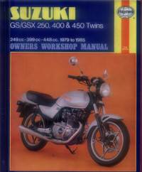
Руководство на английском языке по техническому обслуживанию и ремонту мотоциклов Suzuki GS250/GS400/GS450 и GSX250/GSX400/GSX450 1979-1985 годов выпуска.
- Издательство: Haynes Publishing
- Год издания: 1986
- Страниц: 236
- Формат: PDF
- Размер: 51,6 Mb
Руководство на английском языке по ремонту мотоциклов Suzuki GSX250F.
- Издательство: Suzuki Motor Corporation
- Год издания: 1991
- Страниц: 229
- Формат: PDF
- Размер: 6,9 Mb
Руководство на английском языке по ремонту мотоциклов Suzuki GSX400F.
- Издательство: Suzuki Motor Corporation
- Год издания: —
- Страниц: 292
- Формат: PDF
- Размер: 39,9 Mb

Руководство на английском языке по техническому обслуживанию и ремонту мотоциклов Suzuki GSX600F, GSX750 и GSX750F 1998-2002 годов выпуска.
- Издательство: Haynes Publishing
- Год издания: 2003
- Страниц: —
- Формат: JPG
- Размер: 64,1 Mb

Руководство на английском языке по техническому обслуживанию и ремонту мотоциклов Suzuki GSX600F Katana, GSX750F Katana, GSX1100F Katana 1988-1996 годов выпуска и GSX-R750, GSX-R1100 1985-1992 годов выпуска.
- Издательство: Haynes Publishing
- Год издания: —
- Страниц: 256
- Формат: PDF
- Размер: 37,5 Mb
Руководство на английском языке по ремонту мотоциклов Suzuki GSF650, GSF650S и GSX650F.
- Издательство: Suzuki Motor Corporation
- Год издания: 2007
- Страниц: 620
- Формат: PDF
- Размер: 28,9 Mb
Руководство на английском языке по ремонту мотоциклов Suzuki GSX750E и GSX750ES 1984-1986 годов выпуска.
- Издательство: Suzuki Motor Corporation
- Год издания: —
- Страниц: 309
- Формат: PDF
- Размер: 18,9 Mb
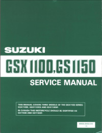
Руководство на английском языке по ремонту мотоциклов Suzuki GS1150 и GSX1100.
- Издательство: Suzuki Motor Corporation
- Год издания: —
- Страниц: 306
- Формат: PDF
- Размер: 42,4 Mb
Руководство на английском языке по ремонту мотоциклов Suzuki GSX1300BK B-King.
- Издательство: Suzuki Motor Corporation
- Год издания: 2007
- Страниц: 686
- Формат: PDF
- Размер: 35,6 Mb
Руководство на английском языке по ремонту мотоциклов Suzuki GSX1300R.
- Издательство: Suzuki Motor Corporation
- Год издания: —
- Страниц: 645
- Формат: PDF
- Размер: 13,9 Mb
Сборник руководств на английском языке по ремонту мотоциклов Suzuki GSX1300R.
- Издательство: Suzuki Motor Corporation
- Год издания: 1999/2000/2001
- Страниц: 503/31/18
- Формат: PDF
- Размер: 107,6 Mb
Руководство на английском языке по ремонту мотоциклов Suzuki GSX1400.
- Издательство: Suzuki Motor Corporation
- Год издания: 2001
- Страниц: 354
- Формат: PDF
- Размер: 23,6 Mb
Руководство на английском языке по эксплуатации и техническому обслуживанию мотоциклов Suzuki GSX1400.
- Издательство: Suzuki Motor Corporation
- Год издания: —
- Страниц: 37
- Формат: PDF
- Размер: 6,0 Mb
Материал из BikesWiki — энциклопедия японских мотоциклов
Перейти к: навигация, поиск
Suzuki GSX600F Katana
Ниже представлены прямые ссылки на скачку сервисной документации.
Для Suzuki GSX600F Katana
- Руководство по ремонту и обслуживанию (Haynes Service & Repair Manual) для Suzuki GSX600F Katana (1988-1996)
- Руководство по ремонту и обслуживанию (Haynes Service & Repair Manual) для Suzuki GSX600F Katana (1998-2002)
- Сервисный мануал (Suzuki Service Manual) на Suzuki GSX600F Katana (1999-2001)
Обзор модели
- Suzuki GSX600F Katana
Источник — «https://bikeswiki.ru/index.php?title=Suzuki_GSX600F_Katana:_мануалы&oldid=9866»
Категория:
- Сервисная документация
4-я Красноармейская, 2А
Санкт-Петербург, 190005
Email: info@lenmoto.ru
Телефон: +7 (921) 930-81-18
Телефон: +7 (911) 928-08-06
Компания ЛенМото
Запчасти, аксессуары, экипировка, тюнинг для мотоциклов, скутеров, квадроциклов, снегоходов, багги, гидроциклов, катеров и лодочных моторов.
Подпишитесь на наши новости
Подписаться
Djebel 250XC и DR-Z 400 S описание приборной панели (RU, 0.2 MB)
DRZ-250 Service Manual (RU, 43.4 MB)
GSX1250fa-Руководство пользователя (RU, 3.7 MB)
Service Manual Suzuki GSF 400 (RU, 4.8 MB)
Service Manual Suzuki Hayabusa K8+ (EN, 35.2 MB)
Susuki GSX 1300 BK Service manual (EN, 37.0 MB)
Suzuki Boulevard C50 2009 (EN, 2.9 MB)
Suzuki Boulevard M109R сервис мануал (RU, 2.7 MB)
Suzuki Boulevard M90 сервис мануал (EN, 40.1 MB)
Suzuki Burgman (AN400) service manual (EN, 18.1 MB)
Suzuki DL 1000 V-Strom руководство пользователя (RU, 3.5 MB)
Suzuki DR250RX SJ45A Djabbel 250 Parts Catalogue 2004-2 (EN, 17.1 MB)
Suzuki GN250 Service Manual (EN, 30.1 MB)
Suzuki GSF 1200 S 2001-2002 Repair Manual (EN, 18.6 MB)
Suzuki GSF 1250 service manual (EN, 35.2 MB)
Suzuki GSF 400 Service Manual `91-`97 (EN, 49.8 MB)
Suzuki GSF 600 S 2000-02 Manual (RU, 26.2 MB)
Suzuki GSF 650 S K7 Manual (RU, 21.3 MB)
Suzuki GSF1250 service manual (EN, 43.1 MB)
Suzuki GSF600/1200 1996-2001 Haynes service manual (EN, 50.8 MB)
Suzuki GSF650A(SA) 2009г -Руководство пользователя (RU, 4.8 MB)
SUZUKI GSF650A/SA (K9) 2009-Руководство пользователя (RU, 4.8 MB)
Suzuki GSF650A/SA 2009-2012 руководство пользователя (RU, 4.8 MB)
Suzuki GSR 600 — Руководство пользователя (RU, 4.6 MB)
Suzuki GSR 750 technical information (EN, 3.0 MB)
Suzuki GSX 1250 FA Manual (RU, 3.7 MB)
Suzuki GSX 1300 BKA руководство пользователя (RU, 3.7 MB)
Suzuki GSX-R 1100W 93-98 Microfiches (EN, 25.3 MB)
Suzuki GSX-R 1100W 93-98 Service Manual (EN, 61.2 MB)
Suzuki GSX-R 600 K8-K9 Servise Manual (EN, 20.6 MB)
Suzuki GSX-R750 2000-2003 (Y-K3) Parts Catalog (EN, 2.5 MB)
Suzuki GSX-R750 K4-K5 (2004) Service Manual (EN, 20.2 MB)
Suzuki GSX650F Service Manual (EN, 43.1 MB)
Suzuki gsxr 750 К6/К7 — Service Manual (EN, 46.0 MB)
Suzuki Intruder 1400 Reparaturanleitung (DE, 12.5 MB)
Suzuki intruder VS 700/750/800 (1987-2008) (RU, 19.9 MB)
Suzuki Intruder VS700-800 Service Repair Maintenance Manual (EN, 0.4 MB)
Suzuki Intruder VS700-800 часть 10 (EN, 0.8 MB)
Suzuki Intruder VS700-800 часть 11 (EN, 0.5 MB)
Suzuki Intruder VS700-800 часть 12 (EN, 0.6 MB)
Suzuki Intruder VS700-800 часть 13 (EN, 0.2 MB)
Suzuki Intruder VS700-800 часть 14 (EN, 0.1 MB)
Suzuki Intruder VS700-800 часть 15 (элетросхемы) (EN, 1.0 MB)
Suzuki Intruder VS700-800 часть 2 (EN, 0.3 MB)
Suzuki Intruder VS700-800 часть 3 (EN, 0.7 MB)
Suzuki Intruder VS700-800 часть 4 (EN, 1.9 MB)
Suzuki Intruder VS700-800 часть 5 (EN, 0.6 MB)
Suzuki Intruder VS700-800 часть 6 (EN, 0.5 MB)
Suzuki Intruder VS700-800 часть 7 (EN, 0.6 MB)
Suzuki Intruder VS700-800 часть 8 (EN, 0.6 MB)
Suzuki Intruder VS700-800 часть 9 (EN, 0.3 MB)
Suzuki RF 400 -Manual (JP, 22.1 MB)
Suzuki RF 400 Каталог запчастей (JP, 50.4 MB)
Suzuki RF600R service manual (EN, 43.4 MB)
Suzuki TL1000S — Руководство пользователя (English) (EN, 44.5 MB)
Suzuki VL 1500 Intruder service manual (98-00) (EN, 34.2 MB)
Suzuki VL 1500 Intruder руководство пользователя (RU, 6.7 MB)
Suzuki VL1500 Service Manual 1998-2000 (EN, 33.1 MB)
Suzuki VL1500 service manual 1998-2000 (EN, 33.1 MB)
Suzuki VL1500 service manual 1998-2000 (EN, 33.1 MB)
Suzuki VL800 Manual (RU, 3.7 MB)
Suzuki VL800-Руководство пользователя (RU, 3.7 MB)
Suzuki VX 800 Service Manual (EN, 7.7 MB)
Suzuki VZ1500 owner’s manual (EN, 1.7 MB)
Suzuki XF 650 Freewind (ccm 644 Engine) Service Manual (EN, 12.7 MB)
Suzuku AN650 Service Manual (EN, 31.4 MB)
User Manual Suzuki Hayabusa K8-L13 (RU, 3.3 MB)
User Manual Suzuki SV 650 1GEN 1/2 (EN, 5.1 MB)
User Manual Suzuki SV 650 1GEN 2/2 (EN, 4.5 MB)
Каталог запчастей на GSF 750. (JP, 8.3 MB)
Мануал Suzuki SV 650 S (RU, 1.8 MB)
Руководство по сервисному обслуиванию SFV400 (RU, 4.8 MB)
Руководство пользователя SUZUKI GSFA(SA) 2009 (RU, 4.8 MB)
Руководство пользователя Suzuki GSX 650 F 08г-12г (RU, 3.2 MB)
Руководство пользователя Suzuki GSX1250fa (RU, 3.7 MB)
- Manuals
- Brands
- SUZUKI Manuals
- Motorcycle
- GSX-R600
Manuals and User Guides for SUZUKI GSX-R600. We have 3 SUZUKI GSX-R600 manuals available for free PDF download: Manual, Service Manual
suzuki GSX-R600 Manual (653 pages)
Brand: suzuki
|
Category: Motorcycle
|
Size: 21.59 MB
Table of Contents
-
Section 1 Engine
63
-
General Information
13
-
Cylinder Identification
17
-
Maintenance and Lubrication
28
-
Scheduled Maintenance
28
-
Lubrication Points
29
-
Front Fork Inspection
47
-
Table of Contents
63
-
Precautions
68
-
Precautions for Engine
68
-
-
Engine General Information and Diagnosis
69
-
General Description
69
-
Injection Timing Description
69
-
Self-Diagnosis Function
71
-
-
Schematic and Routing Diagram
72
-
FI System Wiring Diagram
72
-
Terminal Alignment of ECM Coupler
74
-
-
Component Location
75
-
FI System Parts Location
75
-
-
Diagnostic Information and Procedures
77
-
Engine Symptom Diagnosis
77
-
Self-Diagnostic Procedures
81
-
Use of SDS Diagnosis Reset Procedures
83
-
Show Data When Trouble (Displaying Data at the Time of DTC)
84
-
SDS Check
85
-
DTC Table
89
-
Fail-Safe Function Table
91
-
FI System Troubleshooting
92
-
Malfunction Code and Defective Condition Table
94
-
DTC «C11» (P0340): CMP Sensor Circuit Malfunction
98
-
DTC «C12» (P0335): CKP Sensor Circuit Malfunction
101
-
DTC «C13» (P0105-H/L): IAP Sensor Circuit Malfunction
104
-
DTC «C14» (P0120-H/L): TP Sensor Circuit Malfunction
113
-
DTC «C15» (P0115-H/L): ECT Sensor Circuit Malfunction
120
-
DTC «C21» (P0110-H/L): IAT Sensor Circuit Malfunction
125
-
DTC «C22» (P1450-H/L): AP Sensor Circuit Malfunction
130
-
DTC «C23» (P1651-H/L): to Sensor Circuit Malfunction
139
-
-
DTC «C24» (P0351), «C25» (P0352), «C26» (P0353) or «C27» (P0354): Ignition System Malfunction
146
-
DTC «C28» (P1655): Secondary Throttle Valve Actuator (STVA) Malfunction
146
-
DTC «C29» (P1654-H/L): Secondary Throttle Position Sensor (STPS) Circuit Malfunction
150
-
DTC «C31» (P0705): GP Switch Circuit Malfunction
157
-
DTC «C32» (P0201), «C33» (P0202), «C34» (P0203) or «C35» (P0204): Primary Fuel Injector Circuit Malfunction
159
-
DTC «C36» (P1764), «C37» (P1765), «C38» (P1766) or «C39» (P1767): Secondary Fuel Injector Circuit Malfunction
162
-
DTC «C40» (P0505 / P0506 / P0507): ISC Valve Circuit Malfunction
165
-
DTC «C41» (P0230-H/L): FP Relay Circuit Malfunction
169
-
DTC «C41» (P2505): ECM Power Input Signal Malfunction
172
-
DTC «C42» (P1650): IG Switch Circuit Malfunction
174
-
DTC «C44» (P0130/P0135): HO2 Sensor (HO2S) Circuit Malfunction
174
-
DTC «C46» (P1657-H/L or P1658): EXCV Actuator Circuit Malfunction
180
-
DTC «C49» (P1656): PAIR Control Solenoid Valve Circuit Malfunction
194
-
DTC «C60» (P0480): Cooling Fan Relay Circuit Malfunction
197
-
DTC «C62» (P0443): EVAP System Purge Control Solenoid Valve Circuit Malfunction (E-33 Only)
200
-
DTC «C91» (P0500): Vehicle Speed Sensor Circuit Malfunction
203
-
DTC «C93» (P1769): Steering Damper Solenoid Valve Circuit Malfunction
206
-
-
Specifications
210
-
Service Data
210
-
-
Special Tools and Equipment
211
-
Special Tool
211
-
-
Emission Control Devices
213
-
Precautions
213
-
Precautions for Emission Control Devices
213
-
-
General Description
213
-
Fuel Injection System Description
213
-
Crankcase Emission Control System Description
214
-
Exhaust Emission Control System Description
215
-
Noise Emission Control System Description
216
-
Evaporative Emission Control System Diagram (Only for
216
-
-
Schematic and Routing Diagram
217
-
PAIR System Hose Routing Diagram
217
-
EVAP Canister Hose Routing Diagram
218
-
-
Repair Instructions
219
-
Heated Oxygen Sensor (HO2S) Removal and Installation
219
-
Heated Oxygen Sensor (HO2S) Inspection
219
-
PAIR Reed Valve Removal and Installation
219
-
PAIR Control Solenoid Valve Removal and Installation
221
-
PAIR System Inspection
221
-
Crankcase Breather (PCV) Hose Inspection
222
-
Crankcase Breather (PCV) Hose / Reed Valve / Cover Removal and Installation
223
-
Crankcase Breather (PCV) Cover Inspection
224
-
Crankcase Breather (PCV) Reed Valve Inspection
224
-
Evaporative Emission Control System Removal and Installation (Only for
224
-
Evaporative Emission Control System
224
-
Inspection (Only for
224
-
-
Specifications
229
-
Service Data
229
-
Tightening Torque Specifications
229
-
-
Special Tools and Equipment
229
-
Special Tool
229
-
-
Engine Electrical Devices
230
-
Precautions
230
-
Precautions for Engine Electrical Device
230
-
-
Component Location
230
-
Engine Electrical Components Location
230
-
-
Diagnostic Information and Procedures
230
-
Engine Symptom Diagnosis
230
-
-
Repair Instructions
230
-
ECM Removal and Installation
230
-
CMP Sensor Inspection
231
-
CMP Sensor Removal and Installation
231
-
CKP Sensor Inspection
232
-
CKP Sensor Removal and Installation
232
-
IAP Sensor Inspection
232
-
IAP Sensor Removal and Installation
232
-
TP Sensor Inspection
232
-
TP Sensor Removal and Installation
232
-
TP Sensor Adjustment
233
-
ECT Sensor Removal and Installation
233
-
ECT Sensor Inspection
234
-
IAT Sensor Removal and Installation
234
-
IAT Sensor Inspection
235
-
AP Sensor Inspection
235
-
AP Sensor Removal and Installation
235
-
TO Sensor Inspection
235
-
TO Sensor Removal and Installation
235
-
STP Sensor Inspection
236
-
STP Sensor Adjustment
236
-
STP Sensor Removal and Installation
237
-
STV Actuator Inspection
237
-
STV Actuator Removal and Installation
237
-
ISC Valve Inspection
237
-
ISC Valve Removal and Installation
237
-
ISC Valve Preset and Opening Initialization
238
-
HO2 Sensor Inspection
238
-
HO2 Sensor Removal and Installation
238
-
GP Switch Inspection
238
-
GP Switch Removal and Installation
238
-
-
Specifications
239
-
Service Data
239
-
Tightening Torque Specifications
239
-
-
Special Tools and Equipment
240
-
Special Tool
240
-
-
Engine Mechanical
241
-
Schematic and Routing Diagram
241
-
Camshaft and Sprocket Assembly Diagram
241
-
Throttle Cable Routing Diagram
242
-
-
Diagnostic Information and Procedures
243
-
Engine Mechanical Symptom Diagnosis
243
-
Compression Pressure Check
243
-
-
Repair Instructions
244
-
Engine Components Removable with the Engine in Place
244
-
Air Cleaner Element Removal and Installation
246
-
Air Cleaner Box Removal and Installation
247
-
Air Cleaner Element Inspection and Cleaning
247
-
Throttle Cable Removal and Installation
247
-
Throttle Cable Inspection
247
-
Throttle Cable Play Inspection and Adjustment
247
-
Throttle Body Components
248
-
Throttle Body Construction
249
-
Throttle Body Removal and Installation
250
-
Throttle Body Disassembly and Assembly
251
-
Throttle Body Inspection and Cleaning
255
-
ISC Valve Visual Inspection
256
-
Throttle Valve Synchronization
256
-
ISC Valve Reset
258
-
TP Reset
258
-
Engine Assembly Removal
259
-
Engine Assembly Installation
263
-
Engine Top Side Disassembly
265
-
Engine Top Side Assembly
267
-
Camshaft Inspection
274
-
Camshaft Sprocket
276
-
Cam Chain Tension Adjuster Inspection
276
-
Cam Chain Guide / Cam Chain Tensioner Removal and Installation
277
-
Cam Chain Guide Inspection
277
-
Cam Chain Tensioner Inspection
277
-
Cylinder Head Disassembly and Assembly
278
-
Cylinder Head Related Parts Inspection
282
-
Valve Guide Replacement
285
-
Valve Seat Repair
287
-
Engine Bottom Side Disassembly
287
-
Engine Bottom Side Assembly
294
-
Cylinder Inspection
309
-
Piston Ring Removal and Installation
309
-
Piston and Piston Ring Inspection
311
-
Conrod Crank Pin Bearing Removal and Installation
313
-
Conrod and Crankshaft Inspection
313
-
Conrod Crank Pin Bearing Inspection and Selection
314
-
Crankshaft Journal Bearing Inspection and Selection
316
-
Crankshaft Thrust Clearance Inspection and Selection
319
-
-
Specifications
321
-
Service Data
321
-
Tightening Torque Specifications
323
-
-
Special Tools and Equipment
324
-
Recommended Service Material
324
-
Special Tool
324
-
-
Engine Lubrication System
327
-
Precautions
327
-
Precautions for Engine Oil
327
-
-
Schematic and Routing Diagram
328
-
Engine Lubrication System Chart Diagram
328
-
Oil Pan
328
-
Engine Lubrication Circuit Diagram
329
-
-
Diagnostic Information and Procedures
331
-
Engine Lubrication Symptom Diagnosis
331
-
Oil Pressure Check
331
-
-
Repair Instructions
332
-
Engine Oil and Filter Replacement
332
-
Engine Oil Level Inspection
332
-
Oil Pan / Oil Strainer / Oil Pressure Regulator
332
-
Removal and Installation
332
-
-
Oil Pressure Regulator / Oil Strainer Inspection
333
-
Oil Cooler / Oil Cooler Hose Inspection
334
-
Oil Cooler Removal and Installation
334
-
Oil Pressure Switch Removal and Installation
335
-
Oil Pressure Switch Inspection
335
-
Oil Jet / Oil Gallery Jet Removal and Installation
335
-
Oil Jet / Oil Gallery Jet Inspection
337
-
Oil Pump Removal and Installation
338
-
Oil Pump Inspection
339
-
Oil Pump Drive Gear Removal and Installation
339
-
-
Specifications
340
-
Service Data
340
-
Tightening Torque Specifications
341
-
-
Special Tools and Equipment
341
-
Recommended Service Material
341
-
Special Tool
341
-
-
Engine Cooling System
342
-
Precautions
342
-
Precautions for Engine Cooling System
342
-
Precautions for Engine Coolant
342
-
-
General Description
342
-
Engine Coolant Description
342
-
-
Schematic and Routing Diagram
343
-
Cooling Circuit Diagram
343
-
Water Hose Routing Diagram
344
-
-
Diagnostic Information and Procedures
345
-
Engine Cooling Symptom Diagnosis
345
-
-
Repair Instructions
345
-
Cooling Circuit Inspection
345
-
Radiator Cap Inspection
346
-
Radiator Inspection and Cleaning
346
-
Radiator / Cooling Fan Motor Removal and Installation
346
-
Water Hose Inspection
347
-
Water Hose Removal and Installation
348
-
Radiator Reservoir Tank Inspection
348
-
Radiator Reservoir Tank Removal and Installation
349
-
Cooling Fan Inspection
349
-
Cooling Fan Relay Inspection
349
-
ECT Sensor Removal and Installation
350
-
ECT Sensor Inspection
350
-
Thermostat Removal and Installation
350
-
Thermostat Inspection
351
-
Water Pump Components
352
-
Water Pump Construction
353
-
Water Pump Removal and Installation
353
-
Water Pump Disassembly and Assembly
354
-
Water Pump Related Parts Inspection
357
-
-
Specifications
359
-
Service Data
359
-
Tightening Torque Specifications
359
-
-
Special Tools and Equipment
360
-
Recommended Service Material
360
-
Special Tool
360
-
-
Fuel System
361
-
Precautions
361
-
Precautions for Fuel System
361
-
-
General Description
362
-
Fuel Injection System Description
362
-
-
Schematic and Routing Diagram
363
-
Fuel Tank Drain Hose and Breather Hose Routing Diagram
363
-
-
Diagnostic Information and Procedures
364
-
Fuel System Diagnosis
364
-
-
Repair Instructions
365
-
Fuel Pressure Inspection
365
-
Fuel Pump Inspection
365
-
Fuel Discharge Amount Inspection
366
-
Fuel Pump Relay Inspection
367
-
Fuel Hose Inspection
367
-
Fuel Level Gauge Inspection
367
-
Fuel Tank Construction
368
-
Fuel Tank Removal and Installation
369
-
Fuel Pump Components
370
-
Fuel Pump Disassembly and Assembly
371
-
Fuel Mesh Filter Inspection and Cleaning
373
-
Fuel Injector / Fuel Delivery Pipe / T-Joint Removal and Installation
373
-
Fuel Injector Inspection and Cleaning
373
-
-
Specifications
374
-
Special Tools and Equipment
375
-
Recommended Service Material
375
-
Special Tool
375
-
-
Ignition System
376
-
General Description
376
-
Immobilizer Description (for
376
-
Drive Mode Selector Description
377
-
-
Schematic and Routing Diagram
378
-
Ignition System Diagram
378
-
Ignition System Components Location
378
-
-
Diagnostic Information and Procedures
379
-
Ignition System Symptom Diagnosis
379
-
No Spark or Poor Spark
380
-
-
Repair Instructions
381
-
Ignition Coil / Plug Cap and Spark Plug Removal and Installation
381
-
Spark Plug Inspection and Cleaning
382
-
Ignition Coil / Plug Cap Inspection
382
-
CKP Sensor Inspection
384
-
CKP Sensor Removal and Installation
385
-
Engine Stop Switch Inspection
385
-
Ignition Switch Inspection
385
-
Ignition Switch Removal and Installation
386
-
Drive Mode Selector Inspection
387
-
-
Specifications
388
-
Service Data
388
-
Tightening Torque Specifications
388
-
-
Special Tools and Equipment
389
-
Recommended Service Material
389
-
Special Tool
389
-
-
Starting System
390
-
Schematic and Routing Diagram
390
-
Starting System Diagram
390
-
-
Component Location
390
-
Starting System Components Location
390
-
-
Diagnostic Information and Procedures
390
-
Starting System Symptom Diagnosis
390
-
Starter Motor will Not Run
391
-
Starter Motor Runs but Does Not Crank the Engine
391
-
-
Repair Instructions
392
-
Starter Motor Components
392
-
Starter Motor Removal and Installation
393
-
Starter Motor Disassembly and Assembly
393
-
Starter Motor Inspection
394
-
Starter Relay Removal and Installation
395
-
Starter Relay Inspection
396
-
Turn Signal / Side-Stand Relay Removal and Installation
396
-
Side-Stand / Ignition Interlock System Parts Inspection
397
-
Starter Clutch Removal and Installation
399
-
Starter Clutch Inspection
401
-
Starter Button Inspection
402
-
-
Specifications
403
-
Service Data
403
-
Tightening Torque Specifications
403
-
-
Special Tools and Equipment
404
-
Recommended Service Material
404
-
Special Tool
404
-
-
Charging System
405
-
Schematic and Routing Diagram
405
-
Charging System Diagram
405
-
-
Component Location
405
-
Charging System Components Location
405
-
-
Diagnostic Information and Procedures
405
-
Charging System Symptom Diagnosis
405
-
Battery Runs down Quickly
406
-
-
Repair Instructions
407
-
Battery Current Leakage Inspection
407
-
Regulated Voltage Inspection
407
-
Generator Inspection
407
-
Generator Removal and Installation
408
-
Regulator / Rectifier Construction
412
-
Regulator / Rectifier Removal and Installation
413
-
Regulator / Rectifier Inspection
414
-
Battery Components
415
-
Battery Charging
415
-
Battery Removal and Installation
417
-
Battery Visual Inspection
418
-
-
Specifications
418
-
Service Data
418
-
Tightening Torque Specifications
418
-
-
Special Tools and Equipment
419
-
Recommended Service Material
419
-
Special Tool
419
-
-
Exhaust System
420
-
Precautions
420
-
Precautions for Exhaust System
420
-
-
General Description
420
-
Exhaust Control System Description
420
-
Exhaust Control System Operation
421
-
-
Repair Instructions
423
-
Exhaust Control System Construction
423
-
Exhaust System Components
424
-
EXCV Cable Removal and Installation
425
-
EXCVA Removal and Installation
426
-
EXCVA Inspection
428
-
EXCVA Pulley Inspection
428
-
EXCVA Adjustment
428
-
-
-
Section 2 Suspension
435
-
Precautions
436
-
Precautions for Suspension
436
-
-
Suspension General Diagnosis
437
-
Diagnostic Information and Procedures
437
-
Suspension and Wheel Symptom Diagnosis
437
-
-
Repair Instructions
438
-
Front Fork Components
438
-
Front Fork Removal and Installation
439
-
Front Suspension Adjustment
441
-
Front Fork Disassembly and Assembly
441
-
Front Fork Parts Inspection
448
-
-
Front Suspension
438
-
Specifications
449
-
Service Data
449
-
Tightening Torque Specifications
449
-
-
Special Tools and Equipment
450
-
Recommended Service Material
450
-
Special Tool
450
-
-
Rear Suspension
451
-
Repair Instructions
451
-
Rear Suspension Components
451
-
Rear Suspension Assembly Construction
452
-
Rear Shock Absorber Removal and Installation
453
-
Rear Suspension Inspection
454
-
Rear Shock Absorber Inspection
454
-
Rear Suspension Adjustment
454
-
Rear Shock Absorber Disposal
455
-
Cushion Lever Removal and Installation
456
-
Cushion Lever Inspection
456
-
Cushion Lever Bearing Removal and Installation
457
-
Cushion Rod Removal and Installation
458
-
Cushion Rod Inspection
458
-
Cushion Rod Bearing Removal and Installation
459
-
Swingarm Removal and Installation
460
-
Swingarm Related Parts Inspection
462
-
Swingarm Bearing Removal and Installation
463
-
-
Specifications
465
-
Service Data
465
-
Tightening Torque Specifications
465
-
-
Special Tools and Equipment
466
-
Recommended Service Material
466
-
Special Tool
466
-
-
Wheels and Tires
467
-
Precautions
467
-
Precautions for Wheel and Tire
467
-
-
Repair Instructions
468
-
Front Wheel Components
468
-
Front Wheel Assembly Construction
469
-
Front Wheel Assembly Removal and Installation
470
-
Front Wheel Related Parts Inspection
472
-
Front Wheel Dust Seal / Bearing Removal and Installation
473
-
Rear Wheel Components
475
-
Rear Wheel Assembly Construction
476
-
Rear Wheel Assembly Removal and Installation
477
-
Rear Wheel Related Parts Inspection
477
-
Rear Wheel Dust Seal / Bearing Removal and Installation
479
-
Tire Removal and Installation
481
-
Wheel / Tire / Air Valve Inspection and Cleaning
482
-
Air Valve Removal and Installation
483
-
Wheel Balance Check and Adjustment
484
-
-
Specifications
485
-
Service Data
485
-
Tightening Torque Specifications
485
-
-
Special Tools and Equipment
486
-
Recommended Service Material
486
-
Special Tool
486
-
-
-
Section 3 Driveline / Axle
487
-
Precautions
488
-
Precautions for Driveline / Axle
488
-
-
Diagnostic Information and Procedures
489
-
Drive Chain and Sprocket Symptom Diagnosis
489
-
-
Repair Instructions
489
-
Drive Chain Related Components
489
-
Engine Sprocket Removal and Installation
490
-
Rear Sprocket / Rear Sprocket Mounting Drum Removal and Installation
491
-
Drive Chain Related Parts Inspection
492
-
Sprocket Mounting Drum Dust Seal / Bearing Removal and Installation
493
-
Drive Chain Replacement
495
-
-
Drive Chain / Drive Train / Drive Shaft
489
-
Specifications
498
-
Service Data
498
-
Tightening Torque Specifications
498
-
-
Special Tools and Equipment
499
-
Recommended Service Material
499
-
Special Tool
499
-
-
Advertisement
Suzuki GSX-R600 Service Manual (466 pages)
Brand: Suzuki
|
Category: Motorcycle
|
Size: 52.53 MB
Table of Contents
-
Foreword
2
-
Group Index
2
-
How to Use this Manual
3
-
Component Parts and Work to be Done
3
-
Symbol
4
-
Abbreviations Used in this Manual
5
-
Wire Color
7
-
General Information
8
-
Contents
8
-
Warning/Caution/Note
9
-
Suzuki GSX-R600K4 (’04-Model) View
11
-
Serial Number Location
11
-
Fuel, Oil and Engine Coolant Recommendation Fuel (for USA and Canada)
12
-
Fuel (for Other Countries)
12
-
Engine Oil (for USA)
12
-
Engine Oil (for Other Countries)
12
-
Engine Coolant
13
-
Water for Mixing
13
-
Anti-Freeze/Engine Coolant
13
-
Liquid Amount of Water/Engine Coolant
13
-
Break-In Procedures
14
-
Cylinder Identification
14
-
Information Labels
15
-
Specifications
16
-
Dimensions and Dry Mass
16
-
Drive Train
16
-
Electrical
17
-
Capacities
17
-
Periodic Maintenance
18
-
Periodic Maintenance Schedule
19
-
Periodic Maintenance Chart
19
-
Lubrication Points
20
-
Maintenance and Tune-Up Procedures
21
-
Air Cleaner
21
-
Spark Plug and Ignition Coil/Plug Cap Removal
22
-
Heat Range
22
-
Carbon Deposits
22
-
Spark Plug Gap
23
-
Electrode’s Condition
23
-
Spark Plug and Ignition Coil/Plug Cap Installation
23
-
Valve Clearance
24
-
Valve Clearance Adjustment
26
-
Intake Side
27
-
Tappet Shim Selection Table
27
-
Exhaust Side
28
-
Engine Oil and Oil Filter
29
-
Engine Oil Replacement
29
-
Oil Filter Replacement
30
-
Fuel Line
31
-
Engine Idle Speed
31
-
Throttle Valve Synchronization
32
-
Evaporative Emission Control System (E-33 Only)
32
-
Pair (Air Supply) System
32
-
Throttle Cable Play
33
-
Clutch
33
-
Cooling System
34
-
Engine Coolant Level Check
34
-
Engine Coolant Change
34
-
Air Bleeding the Cooling Circuit
35
-
Radiator Hoses
36
-
Drive Chain
37
-
Checking
37
-
Adjusting
38
-
Cleaning and Lubricating
39
-
Brake Fluid Level Check
40
-
Brake Pads
41
-
Front Brake
41
-
Rear Brake
41
-
Brake Pedal Height
41
-
Brake Light Switch
42
-
Air Bleeding from Brake Fluid Circuit
42
-
Front Brake (Caliper Side)
42
-
Front Brake (Master Cylinder Side)
43
-
Tire Tread Condition
44
-
Tire Pressure
44
-
Steering
45
-
Front Fork
45
-
Rear Suspension
45
-
Exhaust Pipe Bolt and Muffler Bolt and Nut
46
-
Chassis Bolts and Nuts
47
-
Compression Pressure Check
49
-
Compression Pressure Specification
49
-
Compression Test Procedure
49
-
Oil Pressure Check
50
-
Oil Pressure Specification
50
-
Oil Pressure Test Procedure
50
-
Engine
52
-
Engine Components Removable with Engine in Place
53
-
Engine Center
53
-
Engine Right Side
53
-
Engine Left Side
53
-
Engine Removal
54
-
Radiator
55
-
Exhaust Pipe and Muffler
56
-
Electric Parts and Pair Hose
57
-
Engine Sprocket and Gear Shift Lever
58
-
Engine Mounting
59
-
Engine Installation
61
-
Engine Disassembly
67
-
Starter Motor
67
-
Cylinder Head Cover and Pair Reed Valve
67
-
Camshafts
68
-
Cylinder Head
69
-
Oil Pump
72
-
Gearshift System
72
-
Starter Idle Gear
73
-
Starter Clutch
74
-
Cam Chain, Cam Chain Tensioner and Cam Chain Guide
74
-
CKP Sensor
74
-
Generator Cover
75
-
Generator Rotor
75
-
Water Pump
75
-
Gear Position Switch
76
-
Crankcase Breather (PCV) Cover
76
-
Oil Filter
76
-
Lower Crank Case
77
-
Middle Crankcase
78
-
Crankshaft
78
-
Piston and Conrod
78
-
Engine Components Inspection and Service
80
-
Cylinder Head Cover
80
-
CMP Sensor
80
-
Pair Reed Valve
80
-
PCV Hose
81
-
Camshaft Identification
81
-
Cam Wear
81
-
Camshaft Journal Wear
82
-
Сamshaft Runout
83
-
Сam Sprocket
83
-
Сam Chain Tension Adjuster
83
-
Сam Chain Tensioner
84
-
Сam Chain Guide
84
-
Сylinder Head and Valve
84
-
Valve and Valve Spring Disassembly
84
-
Cylinder Head Distortion
86
-
Valve Stem Runout
86
-
Valve Head Radial Runout
86
-
Valve Stem and Valve Face Wear Condition
87
-
Valve Stem Deflection
87
-
Valve Stem Wear
87
-
Valve Guide Servicing
88
-
Valve Seat Width Inspection
89
-
Valve Seat Servicing
90
-
Initial Seat Cut
90
-
Top Narrowing Cut
91
-
Bottom Narrowing Cut
91
-
Final Seat Cut
92
-
Valve Spring
93
-
Valve and Valve Spring Reassembly
94
-
Intake Pipe
95
-
Water Bypass Union
96
-
Clutch Drive Plates Inspection
96
-
Clutch Spring Inspection
97
-
Clutch Bearing Inspection
97
-
Clutch Sleeve Hub/Primary Driven Gear Assembly
97
-
Generator
98
-
Gearshift Shaft/Gearshift Arm Disassembly
99
-
Gearshift Shaft/Gearshift Arm Inspection
99
-
Gearshift Shaft/Gearshift Arm Reassembly
99
-
Oil Pressure Regulator
100
-
Transmission
101
-
Disassembly
101
-
Reassembly
102
-
Transmission Parts Location
103
-
Cylinder Distortion
104
-
Cylinder Bore
104
-
Piston and Piston Ring
105
-
Piston Diameter
105
-
Piston-To-Cylinder Clearance
105
-
Piston Pin and Pin Bore
105
-
Piston Ring-To-Groove Clearance
106
-
Piston Ring Free End Gap and Piston Ring End Gap
106
-
Crankcase
107
-
Gearshift Fork and Gearshift Cam
107
-
Gearshift Fork-To-Groove Clearance
107
-
Gearshift Fork Groove Width
107
-
Gearshift Fork Thickness
108
-
Gearshift Cam Bearing and Gearshift Shaft Bearing
108
-
Bearing Inspection
108
-
Bearing Removal
108
-
Installation
109
-
Oil Jet
111
-
Inspection and Cleaning
111
-
Plug
112
-
Conrod Big End Side Clearance
113
-
Conrod-Big End Bearing Inspection
113
-
Conrod-Big End Bearing Selection
113
-
Crankshaft and Conrod
114
-
Crankshaft Runout
114
-
Conrod Small End I.D.
114
-
Crank Pin O.D.
115
-
Bearing Thickness
115
-
Bearing Selection Table
116
-
Conrod I.D.
116
-
Crankshaft Journal Bearing
118
-
Selection
118
-
Crankcase I.D. Specification
119
-
Crankshaft Journal O.D. Specification
120
-
Bearing Thickness Specification
120
-
Crankshaft Thrust Bearing
121
-
Crankshaft Thrust Clearance Adjustment
121
-
Thrust Bearing Selection Table
122
-
Engine Reassembly
123
-
Piston Ring
123
-
Oil Strainer
133
-
Oil Pan
133
-
Oil Pressure Switch
134
-
Crankcase Breather Cover
135
-
Cam Chain Drive Sprocket
138
-
Cam Chain Tensioner and Cam Chain Guide
138
-
Clutch Cover
146
-
Camshaft
149
-
Cam Chain Tension Adjuster
152
-
FI System Diagnosis
157
-
Precautions in Servicing
159
-
Electrical Parts
159
-
Connector/Coupler
159
-
Fuse
160
-
Ecm/Various Sensors
160
-
Electrical Circuit Inspection Procedure
162
-
Open Circuit Check
162
-
Continuity Check
163
-
Voltage Check
163
-
Short Circuit Check (Wire Harness to Ground)
164
-
Using the Multi-Circuit Tester
165
-
Using the Tester
165
-
FI System Technical Features
166
-
Injection Time (Injection Volume)
166
-
Compensation of Injection Time (Volume)
167
-
Injection Stop Control
167
-
Injection Timing
168
-
FI System Parts Location
169
-
FI System Wiring Diagram
171
-
Self-Diagnosis Function
172
-
User Mode
172
-
Dealer Mode
173
-
TPS Adjustment
175
-
Fail-Safe Function
176
-
FI System Troubleshooting
178
-
Self-Diagnostic Procedures
180
-
Self-Diagnosis Reset Procedure
180
-
Malfunction Code and Defective Condition
181
-
«C11» CMP Sensor Circuit Malfunction
183
-
«C12» CKP Sensor Circuit Malfunction
185
-
«C13» IAP Sensor Circuit Malfunction
187
-
«C14» TP Sensor Circuit Malfunction
190
-
«C15» ECT Sensor Circuit Malfunction
191
-
Output Voltage
193
-
«C21» IAT Sensor Circuit Malfunction
195
-
«C22» AP Sensor Circuit Malfunction
197
-
«C23» to Sensor Circuit Malfunction
200
-
«C28» STV Actuator Circuit Malfunction
202
-
«C29» STP Sensor Circuit Malfunction
204
-
«C31» GP Switch Circuit Malfunction
207
-
«C32», «C33», «C34» or «C35» Fuel Injector Circuit Malfunction
208
-
«C41» FP Relay Circuit Malfunction
210
-
«C42» IG Switch Circuit Malfunction
210
-
«C49» Pair Control Solenoid Valve Circuit Malfunction
211
-
Sensors
213
-
Fuel System and Throttle Body
216
-
Fuel Delivery System
217
-
Fuel System
218
-
Fuel Tank Lift-Up
218
-
Fuel Tank Removal
218
-
Fuel Pressure Inspection
219
-
Fuel Pump Inspection
220
-
Fuel Discharge Amount Inspection
220
-
Fuel Pump Relay Inspection
221
-
Fuel Pump and Fuel Filter Removal
222
-
Construction
222
-
Fuel Mesh Filter Inspection and Cleaning
224
-
Fuel Pump and Fuel Mesh Filter Installation
224
-
Throttle Body Construction
228
-
Air Cleaner Box Removal
229
-
Throttle Body Removal
230
-
Throttle Body Disassembly
231
-
Throttle Body Cleaning
233
-
Throttle Body Reassembly
234
-
Throttle Body Installation
236
-
Air Cleaner Box Installation
237
-
STP Sensor Adjustment
237
-
Fuel Injector Removal
238
-
Fuel Injector Inspection
238
-
Fuel Injector Installation
238
-
Fast Idle Adjustment
239
-
Use for Digital Vacuum Tester
241
-
Use for Vacuum Balancer Gauge
242
-
Calibrating each Vacuum Gauge
242
-
Throttle Position Sensor (TPS) Setting
244
-
Exhaust System
246
-
Precautions for Exhaust System
247
-
Exhaust System Components
247
-
Cooling and Lubrication System
250
-
Cooling Circuit Inspection
252
-
Radiator and Water Hoses
253
-
Radiator Removal
253
-
Radiator Cap Inspection
253
-
Radiator Inspection and Cleaning
253
-
Water Hose Inspection
254
-
Cooling Fan
255
-
Cooling Fan Thermo-Switch
256
-
ECT Sensor
257
-
Temperature Sensor Specification
257
-
Thermostat
258
-
Mechanical Seal
263
-
Oil Seal
263
-
Impeller Shaft Journal
263
-
Seal Washer
263
-
Lubrication System
267
-
Oil Cooler
267
-
Engine Lubrication System Chart
269
-
Engine Lubrication System
270
-
Chassis
273
-
Exterior Parts
275
-
Fastener Removal and Reinstallation
275
-
Screen
276
-
Body Cowling Cover and Lower Bracket Cover
276
-
Right and Left under Cowlings
276
-
Body Cowling
278
-
Right and Left Air Intake Pipes
279
-
Cowling Brace
279
-
Front Seat
279
-
Rear Seat and Seat Tail Cover
280
-
Frame Cover
280
-
Front Wheel Construction
281
-
Axle Shaft
283
-
Wheel Bearing
283
-
Reassembly and Installation
284
-
Brake Disc
285
-
Spacer Nut
286
-
Brake Caliper
286
-
Front Axle
286
-
Front Fork Construction
287
-
Inner and Outer Tubes
291
-
Damper Rod
292
-
Compression Damping Force Adjuster
292
-
Oil Seal and Dust Seal
292
-
Damper Rod Bolt
293
-
Fork Oil
293
-
Fork Spring
294
-
Front Fork Cap Bolt
295
-
Suspension Setting
298
-
Spring Pre-Load Adjustment
298
-
Damping Force Adjustment
298
-
Standard Front Suspension Setting
298
-
Steering Damper Construction
299
-
Steering Construction
301
-
Inner Race
303
-
Stem Nut
304
-
Front Fork and Steering Stem Upper Bracket
305
-
Steering Tension Adjustment
306
-
Handlebars Construction
307
-
Rear Wheel Construction
311
-
Rear Axle
313
-
Wheel Damper
313
-
Sprocket
314
-
Dust Seals
317
-
Rear Sprocket and Sprocket Mounting Drum
317
-
Rear Shock Absorber Construction
319
-
Rear Shock Absorber Scrapping Procedure
321
-
Rear Shock Absorber Gas Release
321
-
Rear Suspension Construction
323
-
Spacer
326
-
Swingarm Bearing
326
-
Cushion Lever Bearing
327
-
Cushion Lever and Cushion Lever Rods
327
-
Swingarm Pivot Shaft
327
Suzuki GSX-R600 Manual (165 pages)
Brand: Suzuki
|
Category: Motorcycle
|
Size: 2.75 MB
Table of Contents
-
Table of Contents
4
-
The Sport of Motorcycling
6
-
Most Accidents Can be Avoided
7
-
If You Don’t Have a Helmet, Buy a Helmet and Wear It Every Time You Ride
7
-
If a Collision Is Imminent, Do Something
8
-
Special Situations Require Special Care
9
-
Know Your Limits
9
-
Be Extra Safety-Conscious on Bad Weather Days
10
-
Practice Away from Traffic
10
-
Inspection before Riding
10
-
Accessories and Loading
10
-
Carrying a Passenger
11
-
Motorcycle Safety Foundation’s «Riding Tips and Practice Guide» Handbook (for Owners in Usa)
11
-
Be Street Smart
11
-
Labels
11
-
Conclusion
12
-
-
Fuel, Engine Oil and Coolant Recommendations
14
-
-
Controls, Equipment and Adjustments
22
-
Location of Parts
23
-
Ignition Switch
26
-
Key
26
-
Instrument Panel
29
-
Left Handlebar
43
-
Right Handlebar
46
-
Fuel Tank Cap
49
-
Gearshift Lever
50
-
Rear Brake Pedal
51
-
Seat Lock and Helmet Holders
51
-
Side Stand
53
-
Suspension Adjustment
54
-
Footrests and Gearshift Lever Position Change
59
-
Break-In and Inspection before Riding
62
-
-
Riding Tips
66
-
Starting the Engine
67
-
Starting off
69
-
Using the Transmission
70
-
Riding on Hills
71
-
Stopping and Parking
72
-
Carrying a Passenger
73
-
-
Accessory Use and Motorcycle Loading
74
-
Accessory Installation Guidelines
75
-
Accessory Use
75
-
Loading Limit
76
-
Loading Guidelines
77
-
Modification
77
-
-
Inspection and Maintenance
80
-
Maintenance Schedule
81
-
Steering Damper Maintenance
85
-
Tools
85
-
Lubrication Points
86
-
Battery
87
-
Air Cleaner
89
-
Spark Plugs
93
-
Engine Oil
99
-
Engine Idle Speed Inspection
105
-
Throttle Cable Play
105
-
Fuel Hose
106
-
Clutch Adjustment
107
-
Engine Coolant
107
-
Drive Chain
109
-
Brakes
113
-
Tires
118
-
Side Stand/Ignition Interlock System
121
-
Front Wheel Removal
122
-
Rear Wheel Removal
125
-
Light Bulb Replacement
128
-
Fuses
134
-
Catalytic Converter
136
-
Troubleshooting
138
-
Advertisement
Advertisement
Related Products
-
Suzuki GSX-R600 2006
-
Suzuki GSX-R600 2007
-
Suzuki GSX R600 2003
-
Suzuki GSX-R1000K5
-
Suzuki GSX-R750W 1993
-
Suzuki GSX-R250
-
Suzuki GSX-R1000/A
-
Suzuki GSX-R1000 2007
-
Suzuki GSX-R750UD
-
Suzuki GSX-R750UF
SUZUKI Categories
Motorcycle
Automobile
Musical Instrument
Offroad Vehicle
Outboard Motor
More SUZUKI Manuals


