На чтение 1 мин Просмотров 109 Опубликовано 14.09.2010
 По просьбе многих из сим сообщества коллектив авторов: А.Павлов, А.Соловьев, А. Самолетиков, А.Карапетян подготовили полноценный перевод на русский язык руководства по эксплуатации модели Boeing 767-300. Размер архива 30мб возможно скачать по ссылке.
Купить за рубли вариант 1
Купить через Леонида (выгоднее)

Уже почти 15 лет пишу новости на этом сайте, и как ни странно, разбираюсь в ваших симуляторах.
Летаю на:
i7 9700k@4600
/RTX4080 MSI
/32Gb DDR4 3200
/Win 11 Pro for Workstation
B767 documentation Просмотр ZIP-архива
avsim_su.diz
--------------------------------------------------
        Этот файл был скачан с Avsim.su
               http://www.avsim.su

    This file was downloaded from AvsimRUs.com
             http://www.avsimrus.com
--------------------------------------------------
http://www.avsim.su/files.phtml?fileid=56627
http://www.avsimrus.com/files.phtml?fileid=56627
--------------------------------------------------
56627-B767-docs.zip
| Имя файла | Дата | Размер |
|---|---|---|
| B767 docs/ | 31.01.2015 17:54 | |
| B767 docs/AFM/ | 31.01.2015 17:51 | |
| B767 docs/AFM/VP-BDI D6T11321.36N rev.44 (15.08.14).pdf | 31.01.2015 17:48 | 125 MB |
| B767 docs/FCOM/ | 31.01.2015 17:51 | |
| B767 docs/FCOM/B767 FCOM rev12.pdf.pdf | 31.01.2015 17:42 | 16 MB |
| B767 docs/FCTM/ | 31.01.2015 17:51 | |
| B767 docs/FCTM/B757-767 FCTM rev13.pdf.pdf | 31.01.2015 17:43 | 2 MB |
| B767 docs/FPPM/ | 31.01.2015 17:52 | |
| B767 docs/FPPM/FPPM 767 PW4060 rev.7.pdf.pdf | 31.01.2015 17:49 | 4 MB |
| B767 docs/Fuel jettison/ | 31.01.2015 17:54 | |
| B767 docs/Fuel jettison/Б-767 FCTM FCOM Fuel jettison.pdf | 31.01.2015 17:54 | 68 KB |
| B767 docs/MEL/ | 31.01.2015 17:52 | |
| B767 docs/MEL/MEL 767 NRW Rev.8.pdf | 31.01.2015 17:45 | 8 MB |
| B767 docs/MEL/NEF_B767.pdf | 31.01.2015 17:44 | 965 KB |
| B767 docs/QRH/ | 31.01.2015 17:51 | |
| B767 docs/QRH/B767 QRH rev.12.pdf | 31.01.2015 17:42 | 3 MB |
| B767 docs/WBM/ | 31.01.2015 17:51 | |
| B767 docs/WBM/767 WBM BWX BWW BMQ BPT rev 13.pdf | 31.01.2015 17:48 | 2 MB |
| B767 docs/Примеры компоновки самолета/ | 31.01.2015 17:54 | |
| B767 docs/Примеры компоновки самолета/767 VP-BOQ rev. 4 02.07.2014.pdf.pdf | 31.01.2015 17:53 | 4 MB |
| B767 docs/Примеры компоновки самолета/767 VQ-BMQ rev.6 25.12.2014.pdf.pdf | 31.01.2015 17:53 | 3 MB |
| B767 docs/Примеры компоновки самолета/767 VQ-BMU rev.4 03 06 2014.pdf.pdf | 31.01.2015 17:54 | 7 MB |
| avsim_su.diz | 15.05.2015 23:55 | 406 B |
| Итого: | 176 MB |

Полный сборник документации по летной эксплуатации B767 авиакомпании «Nordwind» достаточно свежий (на июнь 2014) Прошу не распространять на иных ресурсах.
Включает в себя:
-AFM
-FCOM
-FCTM
-FPPM
-MEL
-QRH
-SATCOM
-WBM
+ Бонус: небольшое руководство по FUEL JETTISON, а так же 3 примера компоновки самолета
→ Размер:
156 MB
→ Дата:
7 лет назад (15.05.2015 21:38)
→ Разрешил модератор:
CAT_III
→ Лицензия:
Freeware — Бесплатная версия, с ограничениями в распространении
→ Скачан:
1754 раза
Новые комментарии
5
Улан-Удэ-Новосибирск
Пятак за родной порт) Но взлетел ты с 08 старой)) Она давно не в работе, используется как рулежка уже) Не знаю какая погода была, но в основном взлет с 26-й всегда и по схеме PILU5A на запад выход)
−
Gleb_Baikal
L-29 для FSX
Для включение радиовысотомера РВ-600 необходимо на правой всплывающей панели (вызывается иконкой «Стрелка вправо» над компасом КИ-13) включить в верхнее положение АЗС «РВ». Записал видео, где показана работа указателя перегрузки. Его включать ничем не надо. РЛЭ к модели не делал, т.к. модель очень простая. Можно пользоваться РЛЭ настоящего Л-29. Ссылка на видео https://www.youtube.com/watch?v=B8_uxiFdM2I
−
Жека55
L-29 для FSX
Самолет понравился, спасибо. А РЛЭ к модели найти где-то можно? А то, акселерометр не шуршит, радиовысотомер тоже… Полагаю, что что-то не включил.
−
~Аноним~
L-29 для FSX
В комментарии , тот что я давал ниже , там есть рекомендация , что нужно поправить — цифры в строках . Руление по ВПП и рулёжке происходит так: Даёте РУД вперёд на определённые проценты — самолёт начинает движение , а затем педаль влево , или в право нажимая на тормоз — самолёт поворачивает . Ну а при взлёте набрав определённую скорость , можно управлять только педалями . Примерно так же как и у Ан-2 .
−
Igan
L-29 для FSX
Что значит «кабина растянута по вертикали»? 2Д-кабина делалась под пропорции экрана монитора 16х9 (основные используемые размеры 3840х2160, 1920х1080). На экранах монитора с другими пропорциями, 2Д-кабина будет выглядеть непропорционально.
−
Жека55
AFCAD’S for FSX
В некоторых аэропортах отсутствуют здания, например в Шереметьево и Внуково, в некоторых указатели находятся прямо на рулежках или на ВПП, например в Чите и в Сочи. Как исправить?
−
AlexandrK
L-29 для FSX
Рулить на Л-29 только с помощью педалей не получится. Настоящий Л-29 управляется с помощью дифференциального торможения. Носовая стойка у него не управляемая. На этой модели Л-29 для FSX сделал простое раздельное торможение от правого и левого тормоза на педалях, и самоориентирующуюся носовую стойку.
−
Жека55
PUSH
1
3
2
within 6 m
— 1 —
English
Quick Reference Guide
for Europe
Ex. Ex.
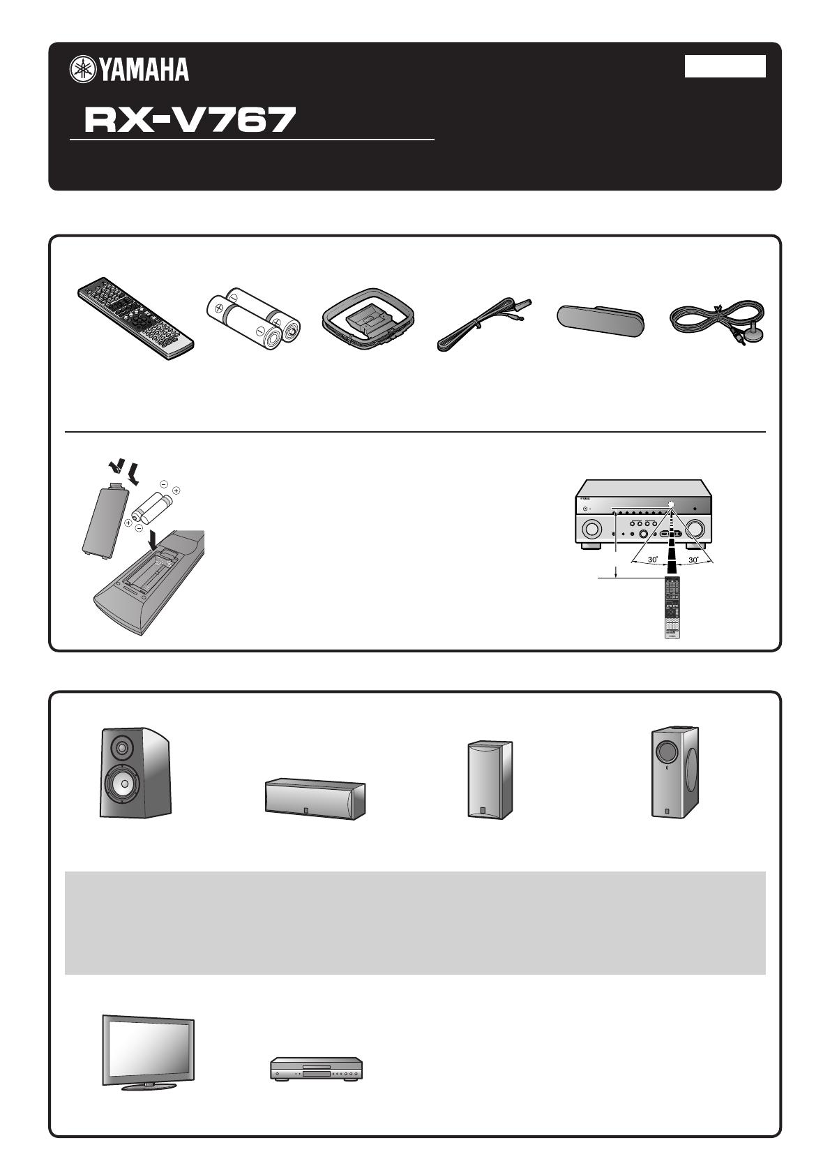
Preparing the remote control
■
Accessories
■
Items necessary for connection
The following accessories are supplied with this product.
Speakers
External components
Remote control
Front speaker
Ex. Ex.
Batteries (2)
(AAA, R03, UM-4)
Center speaker
AM loop antenna
Surround speaker, surround back
speaker, and presence speaker
Indoor FM antenna VIDEO AUX input cover
Active subwoofer
YPAO microphone
1
Take off the battery compartment cover.
2
Insert the two supplied AAA batteries
into the battery case, following the
polarity markings.
3
Snap the battery compartment cover
back into place.
Be sure to aim the remote control directly at the remote
control sensor on this unit during operation.
TV
Cable
• Cables for connecting external components
(may differ depending on the components you are connecting)
• Speaker cables
(a quantity to match the number of speakers you are connecting)
• Audio pin cable
(for subwoofer)
Playback device such as
BD (Blu-ray Disc)/DVD players
• Use speakers with an impedance of at least 6 Ω. 4 Ω speakers can also be used as the front speakers. For more information on speaker
impedance, refer to page 3.
• If you are using a CRT monitor, we recommend that you use magnetically shielded speakers.
• Prepare at least two front speakers. The priority of the other speakers is as follows:
1 Two surround speakers
2 One center speaker
3 One (or two) surround back speaker (s)/presence speakers
7.1
6.1
7.1
— 2 —
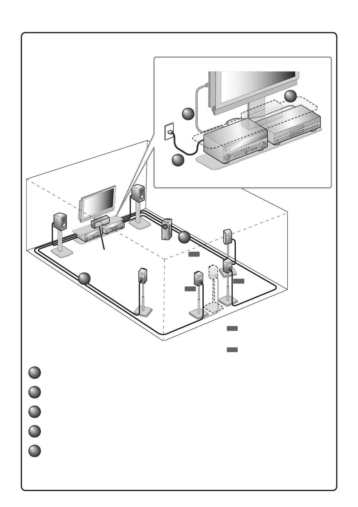
Connect and install as follows the rst time you use this unit.
See the following explanations for the connections for each number.
1
Connect the speakers
2
Connect a TV
3
Connect playback device such as BD/DVD players and recorders
4
Connect the AC power cable
5
Set up the speaker parameters automatically (YPAO)
This unit
TV
Subwoofer
1
1
2
3
4
BD/DVD player
(recorder)
Center speaker
Surround
speaker R
Surround
speaker L
Surround back
speaker L
Surround back
speaker
Surround back
speaker R
Front
speaker R
Front
speaker L
7.1
Connect when using with 7.1-channel speaker
layout. Place the surround back speakers (L/R)
30 cm or more away from each other.
6.1
Connect when using with 6.1-channel speaker
layout. Place the surround back speaker behind
the listening position.
CH INPUT
HDMI 2 HDMI 3
HDMI 4 HDMI 5
CENTER
SURROUND
SURROUND BACK/
BI-AMP
SINGLE
FRONT
SUBWOOFER
AUDI O
OUT
ZONE2
OUT
SUR.BACK
D
SURROUND
SUR.BACK
PRE OUT
SUBWOOFER
1
2
FRONT
R OUT
+12V
.1A MAX.
CENTER
OTE
CENTERSINGLE
SPEAKERS
Z
6.1
7.1 7.1
— 3 —
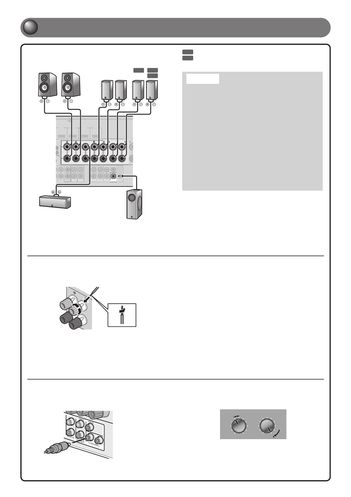
1
Connect the speakers
Front speaker
R L
Surround back
speaker
R L
Surround
speaker
R L
Subwoofer
Center speaker
Connecting the subwoofer
1
C
onnect the subwoofer input jack to the
SUBWOOFER 1 or 2 jack on this unit with an
audio pin cable.
• When connecting the presence speakers, refer to “Presence speaker
connection” in the Owner’s Manual.
• This unit can connect speakers that support Bi-amp connection for front
speakers. Refer to “Bi-amp connection” in the Owner’s Manual for the
details.
7.1
Connect when using with 7.1-channel speaker layout.
6.1
Connect when using with 6.1-channel speaker layout.
Connecting speakers
2
3
1
4
1
Remove approximately 10 mm of insulation from
the ends of the speaker cables, and twist the bare
wires of the cables together rmly so that they will
not cause short circuits.
2
Loosen the speaker terminals.
3
Insert the bare wire of the speaker cable into the
gap on the side of the terminal.
4
Tighten the terminal.
2
Set the subwoofer volume as follows.
Volume: Set to approximately half volume (or slightly less than half).
Crossover frequency (if available): Set to maximum.
Subwoofer examples
VOLUME
MIN MAX
CROSSOVER/
HIGH CUT
MIN MAX
Caution:
• Remove the AC power cable of this unit from the power outlet
before connecting the speakers.
• Generally speaker cables consist of two parallel insulated
cables. One of these cables is a different color, or has a line
running along it, to indicate different polarity. Insert the different
colored (or lined) cable into the “+” (positive, red) terminal
on this unit and the speakers, and the other cable into the “-”
(minus, black) terminal.
• Be careful that the core of the speaker cable does not touch
anything or come into contact with the metal areas of this unit.
This may damage this unit or the speakers. If the speaker cables
short circuit, “CHECK SP WIRES!” will appear on the front panel
display when this unit is switched on.
• This unit is con gured for 8 Ω speakers at the factory setting.
When connecting 6 Ω speakers, con gure the speaker
impedance setting of this unit to 6 Ω. When this unit is
con gured for 6 Ω speakers, 4 Ω speakers can also be used as
the front speakers. For more information on setting the speaker
impedance, refer to “Changing speaker impedance” in the
Owner’s Manual.
HDMI OUT
12
ARC ARC
SELECTABLE
DOCK
(
TV
)
AV 3
AV
4
AV
5
AV
6
AUDIO
1
AUDIO
2
MULTI CH I
(
CD
)
COAXIAL
OPTICAL
VIDEO
HDMI 1
(
BD/DVD
)
AV
OUT
S
SURROUND
TRIGGER OUT
+12V
0.1A MA
FRONT
IN
REMOTE
OUT
S VIDEO
ANTENNA
FM
GND
AM
75
PHONO
GND
ANTENNA
FM
GND
AM
75
OPTICAL
AV 1
AV 2
COAXIAL
COMPONENT
VIDEO
P
R
P
B
Y
COMPONENT
VIDEO
VIDEO
MONITOR OUT
P
R
P
B
Y
VIDEO
VIDEO
COMPONENT
VIDEO
V
P
R
Y
V
HDMI
P
R
Y
P
B
P
B
HDMI
HDMI
A When using an HDMI
compatible TV.
B When using a component
video input-compatible TV.
C
When using a TV compatible
with video input only.
— 4 —
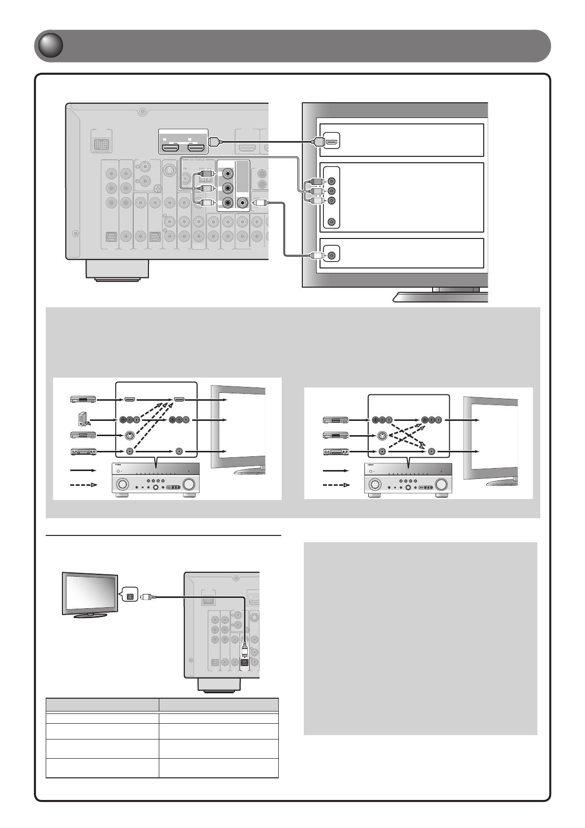
2
Connect a TV
Listening to TV audio
To playback TV audio on this unit, connect the TV audio output to this unit.
Connect the following input jacks, matching the audio output jacks on your TV.
When viewing your TV, select the appropriate input source on this unit.
Audio
output
DOCK
(
TV
)
AV
3
AV 4
AV 5
(
CD
)
COAXIAL
OPTICAL
VIDEO
S VIDEO
PHONO
GND
OPTICAL
AV 1
AV 2
COAXIAL
COMPONENT
VIDEO
P
R
P
B
Y
1
ARC
OPTICAL
O
O
Audio output from TV Input jack on this unit
Optical digital output AV1 or AV4
Coaxial digital output AV2 or AV3
Analog output
One of AV5, AV6, AUDIO1, AUDIO2,
and VIDEO-AUX
HDMI Audio Return Channel
(Described in the right column)
HDMI OUT 1 or HDMI OUT 2
✽ Connecting to AV4 allows you to playback TV audio just by pressing the
TV under SCENE key.
When using an HDMI compatible TV that supports
Audio Return Channel functions and / or HDMI Control functions
(e.g., Panasonic VIERA Link), you can enjoy the TV sound on this
unit as follows:
When using a TV that supports the Audio Return Channel
function and HDMI Control function
The audio / video output from the unit to the TV and audio output
from the TV to the unit are possible using a single HDMI cable.
The input source is switched automatically to match operations
carried out on the TV, and that makes TV sound control easier to
use.
For the connections and settings, refer to “Using the HDMI Control
function” in the Owner’s Manual.
When using a TV that supports HDMI Control functions
When HDMI Control functions are enabled on the unit, input source
can be switched automatically to match operations carried out on
the TV.
For the connections and settings, refer to “Using the HDMI Control
function” in the Owner’s Manual.
If your TV has multiple inputs, connect with the following priority (A to C).
Video input to this unit is output to a TV using output jacks of the
same kind.
When connecting to an HDMI compatible TV
Video signal such as component video and video received by this unit
is converted to HDMI and output to the TV. Just select HDMI input on
the TV to view video from any external source connected to this unit.
You can change the resolution and aspect ratio when converting to
HDMI to suit your requirements.
COMPONENT
VIDEO
HDMI
VIDEO
COMPONENT
VIDEO
HDMI
VIDEO
S VIDEO
Input Output
HDMI input
Component
video input
Video input
Through
Converted
TV
When connecting to a non-HDMI compatible TV
Connect to the TV using the same type of connection that you used to
connect to the playback device, and change the inputs on your TV to
match that of the playback device you are using for playback.
If the playback device and TV are equipped with different types
of analog video jacks, this unit will convert the component video,
S-video or video signal to component video or video signal, according
to the type of video input jacks used by the TV. For more information
on video signal conversion, refer to “Connecting a TV monitor” in the
Owner’s Manual.
COMPONENT
VIDEO
VIDEO
COMPONENT
VIDEO
VIDEO
S VIDEO
Input Output
Component
video input
Video input
Through
Converted
TV
AC power cable
To the power outlet
SURROUND BACK/
BI-AMP
SINGLE
EXTRA SP
SUR.BACK
PRE OUT
SUBWOOFER
1
2
CENTERSINGLE
SPEAKERS
MAINS
ZONE2/PRESENCE
— 5 —
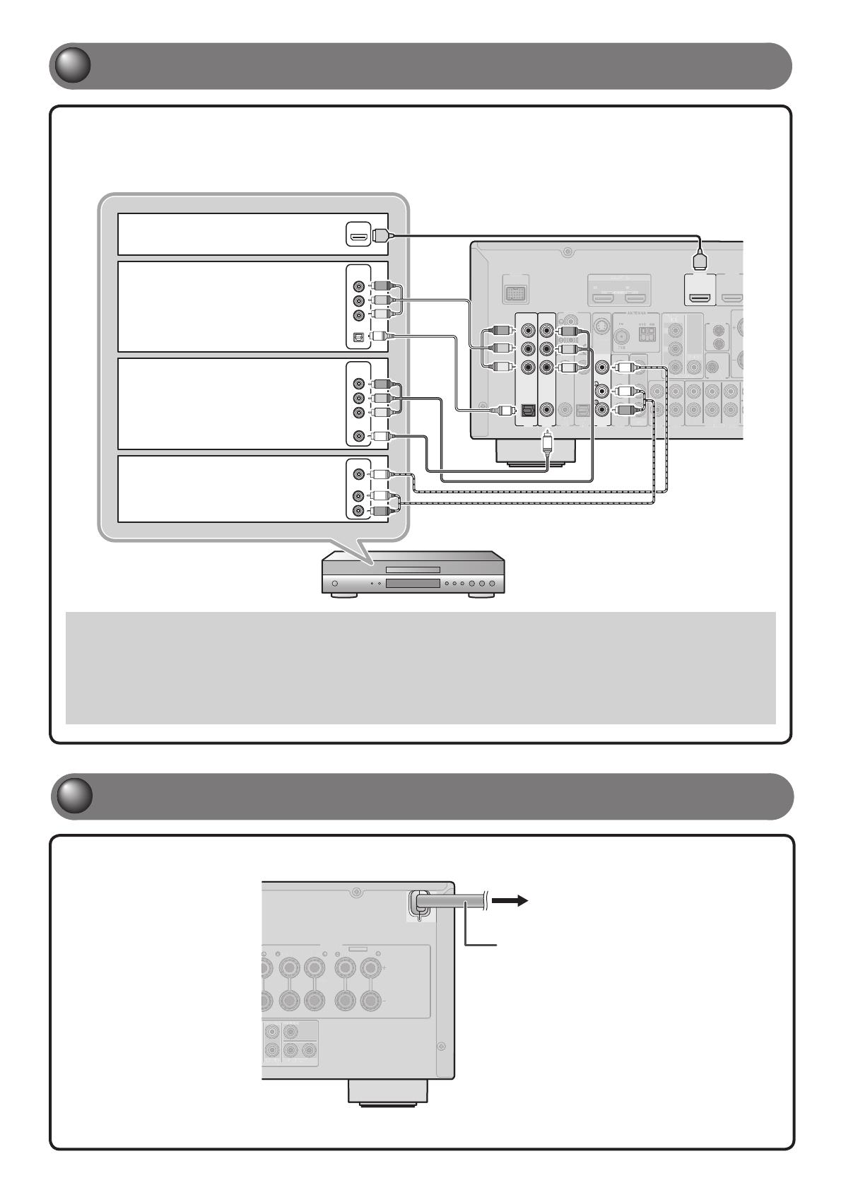
3
Connect playback device such as BD/DVD players and recorders
• When playback, select the corresponding input source to which the jack is connected.
• At the default settings, input sources and sound programs are preset on the SCENE keys. When a playback device is connected to HDMI 1,
pressing BD/DVD under SCENE key selects the HDMI 1 input. When a playback device is connected to AV3, pressing CD under SCENE selects
the AV3 input. The input source and sound program preset on the SCENE key can be changed. For more information on the SCENE function,
refer to “Changing input settings with a single key (SCENE function)” in the Owner’s Manual.
• If necessary, you can connect components that cannot be connected using the above methods, such as devices that output video from
component video output jacks and audio from analog output jacks. Refer to “Connecting external components” in the Owner’s Manual for
details.
If your playback device has multiple audio/video outputs, connect with the following priority
(A to D) to enjoy a higher quality sounds and images.
HDMI OUT
12
ARC ARC
SELECTABLE
DOCK
(
TV
)
AV 3
AV 4
AV 5
AV 6
AUD
IO 1
AUD
IO 2
M
ULTI CH INPUT
(
CD
)
COAXIAL
OPTICAL
VIDEO
HDMI 1
(
BD/DVD
)
HDMI 2
AV
OUT
S
SUR.BACK
SURROUND
TRIGGER OUT
+12V
0.1A MAX.
FRONT
IN
REMOTE
OUT
S VIDEO
ANTENNA
FM
GND
AM
75
PHONO
GND
ANTENNA
FM
GND
AM
75
OPTICAL
AV 1
AV 2
COAXIAL
COMPONENT
VIDEO
P
R
P
B
Y
COMPONENT
VIDEO
VIDEO
MONITOR OUT
P
R
P
B
Y
AUDIO
VIDEO
COMPONENT
VIDEO
COAXIAL
OPTICAL
COMPONENT
VIDEO
HDMI
HDMI
P
R
P
R
Y
O
R
R
HDMI
Y
P
B
P
B
O
P
B
P
B
C
C
V
V
P
R
Y
Y
P
R
L
L
A When playback device is capable
of HDMI output
B When playback device is capable
of component video output (with
optical digital audio output)
C When playback device is capable
of component video output (with
coaxial digital audio output)
D When playback device is capable
of video output (with analog audio
output) only
4
Connect the AC power cable
Continues to
the next page
— 6 —
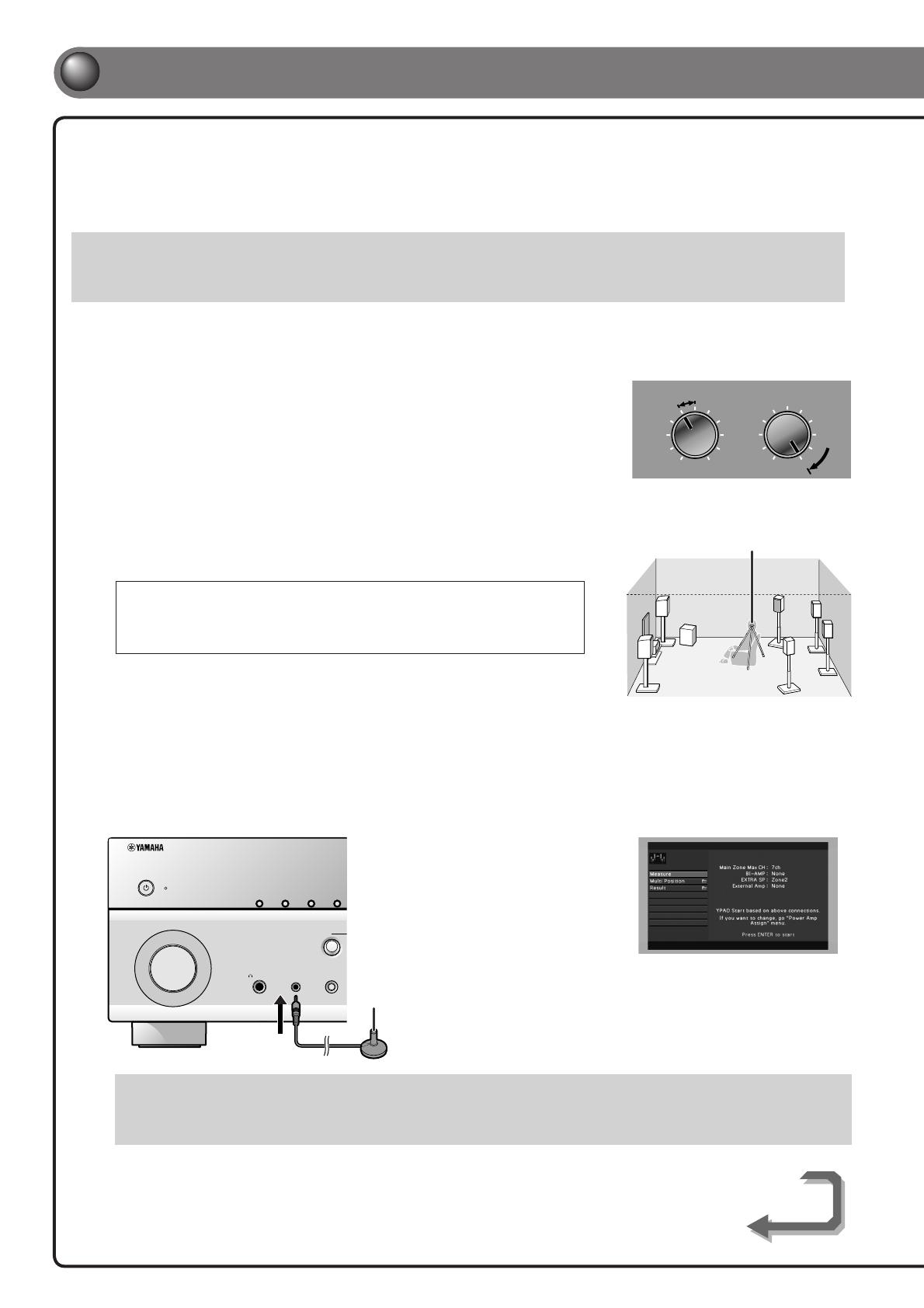
When all connections are complete, adjust the con guration, sizes, and volume
balance of the speakers to provide an optimal sound eld. This unit is equipped with a
Yamaha Parametric Room Acoustic Optimizer (YPAO) function that adjusts the speaker
balance automatically with a simple procedure.
When using YPAO, a test tone will be output from the speakers for approximately 3 minutes to measure acoustics. Be aware of the following when
using YPAO.
• The test tone is output at high volume. Refrain from using this function at night when it may be a nuisance to others.
• Take care that the test tone does not frighten small children.
YPAO operations can be viewed on the front panel display or TV screen. TV display is used here to explain operation.
1
Check the following before using YPAO.
This unit
• The headphones are removed.
TV
• This unit is connected to the TV correctly.
• The power is turned on.
• The video input to which the video output
from this unit has been selected.
Subwoofer
• The power is turned on.
• Volume is set to approximately half, and the
cross-over frequency (if present) is set to
maximum.
2
Place the supplied YPAO microphone at ear height in your listening
position.
• When positioning the microphone, we recommend that you use equipment that allows you
to adjust the height (such as a tripod) as a microphone stand. When using a tripod, use the
tripod screws to x the microphone in place.
• Measuring, for multiple listening positions, is also available. For more information, refer to
“Setting up the speaker parameters automatically (YPAO)” in the Owner’s Manual.
3
Press RECEIVER A on the remote control to switch this unit on.
4
Connect the YPAO microphone to the YPAO MIC jack on the front panel.
YPAO microphone
PHONES
YPAO MIC
SILENT
CINEMA
TONE
CONTROL
BD
DVD
INPUT
INFOZONE
CONTROL
ZONE2
MAIN ZONE
MEMORY
“Mic On. View ON SCREEN” appears
on the front panel display, and then
the display at right appears on the
TV screen.
This completes preparation. To achieve more accurate results, take note of the following when measuring acoustics.
• It takes approximately 3 minutes to accurately measure acoustics. Keep the room as quiet as possible while acoustics are measured.
• Wait in a corner of the room, or leave it entirely, while acoustics are measured to avoid creating an obstruction between the speakers
and the YPAO microphone.
5
Set up the speaker parameters automatically (YPAO)
YPAO microphone
VOLUME
MIN MAX
CROSSOVER/
HIGH CUT
MIN MAX
Subwoofer examples
— 7 —
SCENE
RETURN
VOLUME
ENHANCER
SUR. DECODE
STRAIGHTSLEEP PURE DIRECT
HDMI
AV
AUDIO
1234
125
V-AUX
FM
INFO
MEMORY
AM
PRESET
PA RT Y
MOVIE MUSIC
BD
DVD
TV
CD
RADIO
MUTE
ENTER
7856
90
10
1234
REC
ENT
TV
TV VOL TV CH
TOP
MENU
POP-UP
MENU
DISPLAY
SOURCE
MAIN
ZONE 2
RECEIVER
CODE SET
INPUT
MUTE
DOCK
HDMI OUT
MULTI
OPTION
ON SCREEN
5
1234
6
PHONO
TUNER
TUNING
ON SCREEN
RECEIVER A
ENTER, Cursor
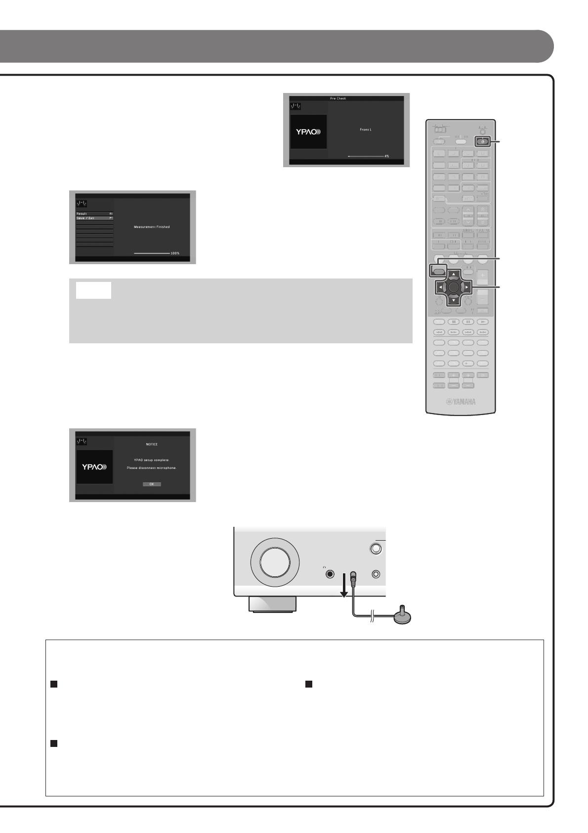
5
Use the cursor B/C to select the “Measure” and
press ENTER to start measurement.
When “Multi Position” is set to “Yes” (default), the measurement of
multiple positions will follow.
Refer to “Setting up the speaker parameters automatically (YPAO)”
for details on “Multi Position” in the Owner’s Manual.
The following display appears if measurement nishes without any
problems.
Result
Displays the results of automatic acoustics measurement and sets
the equalizer (parametric equalizer) to provide a uni ed sound
eld. For details, refer to “Reviewing and reloading the automatic
setup parameters” in the Owner’s Manual.
Save/Exit
Applies the result to the speaker setup and nishes the automatic
measurement.
Note
If a problem occurs, an error message or report is displayed either during or after acoustic
measurement. Refer to “When an error message is displayed during measurement,” or “When a
warning message is displayed after measurement” in the Owner’s Manual to resolve the problem
and measure acoustics with YPAO again.
6
Use the cursor C to select “Save/Exit” and press ENTER.
7
Use the cursor D/E to select “SAVE” and press ENTER.
When the display at left appears, the YPAO setup is complete.
8
Press ENTER.
YPAO is automatically terminated. Disconnect
the YPAO microphone.
You can use the following functions with this unit. For details on the operations, refer to the Owner’s
Manual on the supplied CD-ROM.
PHONES
YPAO MIC
SILENT
CINEMA
TONE
CONTROL
BD
DVD
INPUT
Adjustment for various parameters to match your
listening environment
— Sound quality control with a parametric equalizer <PEQ Select>
— Easy listening at low volumes <Adaptive DRC>
— Adjusting volume between input sources <Volume Trim>
External device connection and playback
— Connections and playback from BD/DVD players (recorders), TV audio,
and other devices
— Playback from an iPod/iPhone
— Playback from a Bluetooth device
FM/AM tuner
— Manual preset tuning
— Radio Data System tuning
— Automatic traffic information reception
etc.
SCENE
RETURN
VOLUME
ENHANCER
SUR. DECODE
STRAIGHTSLEEP PURE DIRECT
HDMI
AV
AUDIO
1234
125
V-AUX
FM
INFO
MEMORY
AM
PRESET
PART Y
MOVIE MUSIC
BD
DVD
TV
CD
RADIO
MUTE
ENTER
7856
90
10
1234
REC
ENT
TV
TV VOL TV CH
TOP
MENU
POP-UP
MENU
DISPLAY
SOURCE
MAIN
ZONE 2
RECEIVER
CODE SET
INPUT
MUTE
DOCK
HDMI OUT
MULTI
OPTION
ON SCREEN
5
1234
6
PHONO
TUNER
TUNING
A
B
C
D
E
F
VIDEO
AUX
PHONES
YPAO MIC
SILENT
CINEMA
TONE
CONTROL
STRAIGHT
VOLUM E
TV
BD
DVD
CD
RADIO
INPUT
PROGRAM
SCENE
VIDEO
AUDIO
HDMI IN
LR
INFOZONE
CONTROL
ZONE2
MAIN ZONE
MEMORY
PRESET
TUNING
PURE DIRECT
FM AM
A B C D
G F
— 8 —
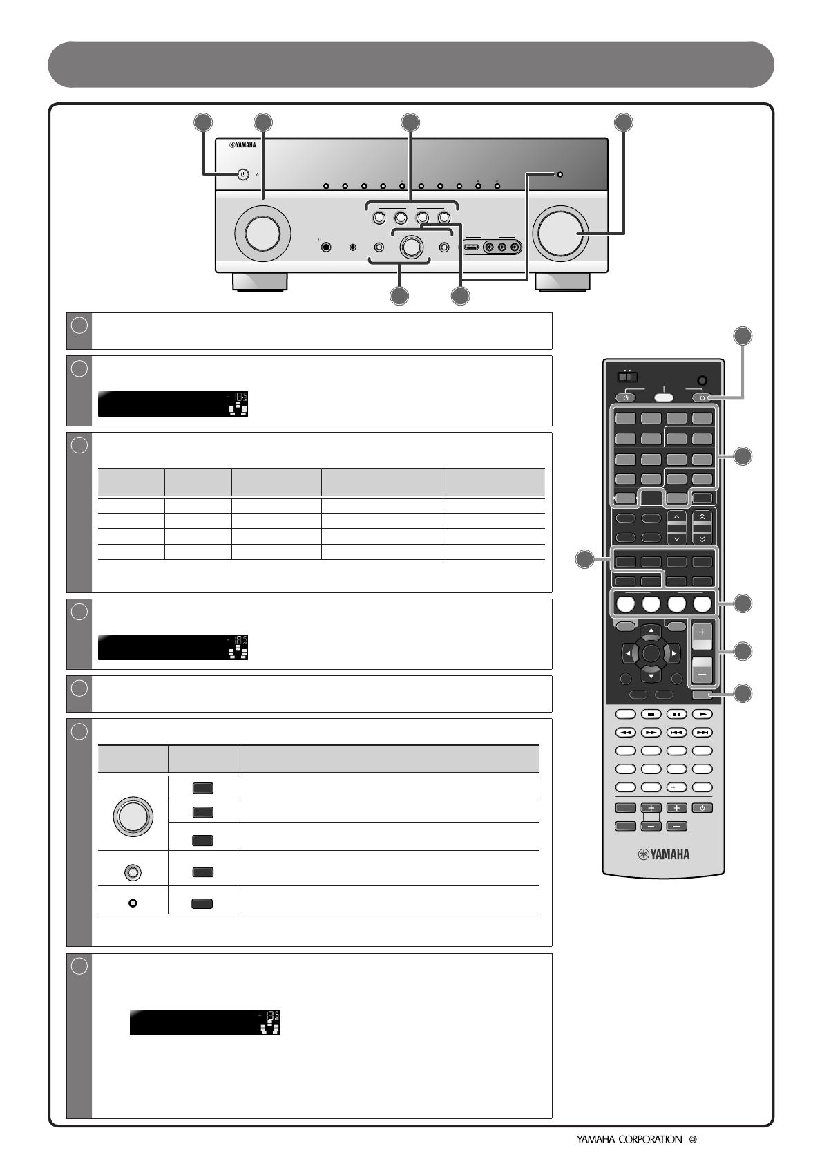
Operation guide
A
Switches this unit between on and standby mode
This unit switches between on and standby mode every time you press this key.
B
Choose an input source to listen to
The name of the selected input source appears on the front panel display.
SW
C
L
SL SR
R
HDMI1
VOL.
SBL SBR
C
Switches between input settings
You can switch input sources and sound eld programs with a single key.
SCENE Input
Sound field
program
Compressed Music
Enhancer mode
HDMI OUT
BD/DVD HDMI1 Drama Off HDMI OUT 1+2
TV AV4 STRAIGHT On HDMI OUT 1+2
CD AV3 STRAIGHT Off HDMI OUT 1+2
RADIO TUNER STRAIGHT On HDMI OUT 1+2
— Pressing and holding this key allows you to store input sources/sound eld programs.
— Press this key when this unit is in standby mode to switch on the unit.
D
Adjusts the volume level
The current volume level is displayed on the front panel display.
SW
C
L
SL SR
R
SBL SBR
Volume -18.5dB
VOL.
E
Mutes the sound
The indicator blinks while the sound is muted.
F
Select sound eld programs and sound decoders
Front
panel
Remote
control
Description
PROGRAM
MOVIE
Selects sound eld programs optimized for viewing movies, dramas,
and sports.
MUSIC
Selects sound eld programs optimized for appreciating music.
SUR. DECODE
Selects surround decoders such as Dolby Pro Logic II.
STRAIGHT
STRAIGHT
Switches to Straight decoding mode for stereo/multi-channel
playback without using a sound eld program.
PURE DIRECT
PURE DIRECT
Switches to Pure Direct mode for faithful reproduction of audio.
— When playing back compression artifacts, press ENHANCER to turn on the Compressed
Music Enhancer mode.
G
Adjusting high/low-frequency sound (Tone control)
1
Press TONE CONTROL to select “Treble” or “Bass.”
SW
C
L
SL SR
R
TONE
Treble +0.5dB
VOL.
SBL SBR
2
Rotate PROGRAM selector to adjust the output level in those
frequency ranges.
— You can set the tone control for speakers and headphones separately. Connect the
headphones when adjusting the headphone tone control.
— If you set an extreme tone balance, sounds may not match those from other channels.
© 2010 Yamaha Corporation
YC515A0/QREN2
/
81-765/766/767 «Москва»Руководство по эксплуатации
12.07.202214.07.202202850

Состав постоянного формирования из вагонов метрополитена моделей 81-765, 81-766, 81-767
Руководство по эксплуатации. Часть 1. 7650.30.00.001 РЭ
Скачать PDF 928 КБ
Руководство по эксплуатации. Часть 2. Альбом иллюстраций. 7650.30.00.001 РЭ1
Скачать PDF 18,6 МБ
Руководство по эксплуатации. Часть 3. Техническое обслуживание и ремонт. 7650.30.00.001 РЭ2
Скачать PDF 726 КБ
Смотреть руководство для Yamaha RX-V767 ниже. Все руководства на ManualsCat.com могут просматриваться абсолютно бесплатно. Нажав кнопку «Выбор языка» вы можете изменить язык руководства, которое хотите просмотреть.

MANUALSCAT | RU
Вопросы и ответы
У вас есть вопрос о Yamaha RX-V767, но вы не можете найти ответ в пользовательском руководстве? Возможно, пользователи ManualsCat.com смогут помочь вам и ответят на ваш вопрос. Заполните форму ниже — и ваш вопрос будет отображаться под руководством для Yamaha RX-V767. Пожалуйста, убедитесь, что вы опишите свои трудности с Yamaha RX-V767 как можно более детально. Чем более детальным является ваш вопрос, тем более высоки шансы, что другой пользователь быстро ответит на него. Вам будет автоматически отправлено электронное письмо, чтобы проинформировать вас, когда кто-то из пользователей ответит на ваш вопрос.
Задать вопрос о Yamaha RX-V767
- Бренд:
- Yamaha
- Продукт:
- Приемники
- Модель/название:
- RX-V767
- Тип файла:
- Доступные языки:
- английский