-
Contents
-
Table of Contents
-
Bookmarks
Quick Links
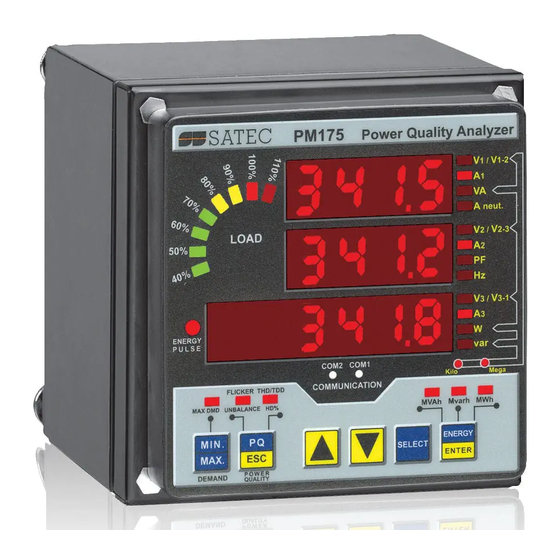
Powermeter and Power
Series PM175
Quality Analyzer
Installation and Operation Manual
BG0415 Rev. A7
Related Manuals for Satec PM175
Summary of Contents for Satec PM175
-
Page 1
Powermeter and Power Series PM175 Quality Analyzer Installation and Operation Manual BG0415 Rev. A7… -
Page 2: Limited Warranty
During operation of the device, hazardous voltages are present on input terminals. Failure to observe precautions can result in serious or even fatal injury or damage to equipment. All trademarks are property of their respective owners. Copyright 2006-2008 Series PM175 Powermeters…
-
Page 3: Table Of Contents
Navigation Buttons ………………..41 Selecting Menus ………………… 41 Entering the Password ……………….. 42 Selecting a Menu Entry ………………. 42 Viewing and Changing Setup Items …………….. 42 Menu Operations ………………… 43 Basic Device Settings ………………..43 Device Options …………………. 45 Series PM175 Powermeters…
-
Page 4
Configuring the EN50160 Recorders …………… 102 EN50160 PQ Recorder Setup …………….. 103 EN50160 Harmonics Limits Setup …………….105 EN50160 Advanced Setup ………………106 Clearing EN50160 Evaluation Counters …………..107 Configuring Communication Protocols …………107 Configuring Modbus ………………… 107 Configuring DNP3………………..108 Series PM175 Powermeters… -
Page 5
Appendix C Setpoint Triggers and Actions …….. 146 Appendix D Parameters for Monitoring and Data Logging Appendix E EN50160 Statistics Log Files ……..163 Appendix F Data Scales …………..167 Appendix G Device Diagnostic Codes ……..168 Series PM175 Powermeters… -
Page 6: Chapter 1 General Information
C hapter 1 General Information Mechanical Installation Chapter 1 General Information The PM175 is a compact, multi-function, three-phase AC powermeter and power quality analyzer specially designed to meet the requirements of users ranging from electrical panel builders to substation operators.
-
Page 7
Two communication ports; communications options available: COM1: RS-232/RS-422/RS-485 56K Dial-up modem Ethernet 10/100BaseT, eXpertPower enabled COM2: RS-422/RS-485 Modbus RTU, Modbus ASCII and Modbus/TCP, DNP3 and DNP3/TCP (with firmware V25.2.01 and later) communication protocols Series PM175 Powermeters… -
Page 8
Total Energy Total kWh Import & Export Total kvarh Import & Export Total kvarh Net Total kVAh Energy per Phase kWh Import per phase Series PM175 Powermeters… -
Page 9
Day and Time Pulse Counters Analog Inputs (optional) Digital Inputs Relay Outputs Remote Relay Control Alarm Triggers/Setpoints Self-diagnostics Series PM175 Powermeters… -
Page 10: Chapter 2 Installation
C hapter 2 Installation Mechanical Installation Chapter 2 Installation Mechanical Installation Panel Mounting Figure 2-1 Dimensions Series PM175 Powermeters…
-
Page 11
Figure 2 -2 STEP 1 (ANSI 4″ round cutout): Mount the display module in cutout Figure 2 -3 STEP 1 (DIN 92x92mm square cutout): Mount the display module in cutout Figure 2 -4 STEP 2: Assemble the four locating studs Series PM175 Powermeters… -
Page 12
C hapter 2 Installation Mechanical Installation Figure 2 -5 STEP 3: Slide and position the meter on locating studs Figure 2 -6 STEP 4: Affix the meter using the thumb nuts Series PM175 Powermeters… -
Page 13: Din Rail Mounting
C hapter 2 Installation Mechanical Installation DIN Rail Mounting The PM175 can be mounted on a 35-mm DIN rail. The display module is mounted separately on the switchboard panel and is connected to the meter by a communication cable (see Remote Display Installation).
-
Page 14: Remote Display Installation
(ANSI 4″ round or DIN 92×92 mm square) Figure 2-9 Display cutout dimensions STEP 1: Insert the display module into cutout. STEP 2: Fasten washers and nut on screws. Figure 2-10 ANSI 4″ or DIN 92×92 mm display mounting Series PM175 Powermeters…
-
Page 15
C hapter 2 Installation Remote Display Installation Special Cutout Figure 2-11 Panel cutout dimensions Figure 2-12 Display mounting Series PM175 Powermeters… -
Page 16: Electrical Connection
If required, the remote display may be connected to one of the regular meter ports COM1 or COM2 via a three-wire RS-485 communication cable using a separate 12V DC power source as shown in Figure 2-14. See Communications Connections for connector pin-outs and connection diagrams. The meter Series PM175 Powermeters…
-
Page 17
C hapter 2 Installation Remote Display Installation port settings must be as follows: Modbus RTU protocol, RS-485 interface, 19200 baud, 8-bits/no parity. Series PM175 Powermeters… -
Page 18: Electrical Installation
Before installation ensure that all incoming power sources are shut OFF. Failure to observe this practice can result in serious or even fatal injury and damage to equipment. Typical Installation DIGITAL INPUTS ANALOG INPUTS RELAYS ANALOG OUTPUTS COM.1 COM.2 Figure 2 -15 Typical Installation Series PM175 Powermeters…
-
Page 19: Terminals
DC power supply: connect the positive wire to terminal 12 and the negative wire to terminal 10. Chassis Ground Connection Connect the chassis ground of the device to the switchgear earth ground using a dedicated wire greater than 2 mm AWG. Series PM175 Powermeters…
-
Page 20: Wiring Diagrams
4-wire 3-element Delta direct connection using 3 CTs 4Ln3 or 4LL3 2-23 3-wire 2½-element Broken Delta connection using 2 PTs, 3 CTs 3bLn3 or 3bLL3 2-24 Figure 2-17 3-Wire 2-Element Direct Connection Using 2 CTs. Wiring Mode = 3dir2 Series PM175 Powermeters…
-
Page 21
C hapter 2 Installation Electrical Installation Figure 2-18 4-Wire Wye 3-Element Direct Connection Using 3 CTs. Wiring Mode = 4LL3 or 4Ln3 Figure 2-19 4-Wire Wye 3-Element Connection Using 3 PTs, 3 CTs. Wiring Mode = 4LL3 or 4Ln3 Series PM175 Powermeters… -
Page 22
C hapter 2 Installation Electrical Installation Figure 2-20 3-Wire 2-Element Open Delta Connection Using 2 PTs, 2 CTs. Wiring Mode = 3OP2 Figure 2-21 4-Wire Wye 2½-Element Connection Using 2 PTs, 3 CTs. Wiring Mode = 3LL3 or 3Ln3 Series PM175 Powermeters… -
Page 23
C hapter 2 Installation Electrical Installation This configuration provides accurate power measurements only if the voltages are balanced. Figure 2-22 3-Wire Open 2½-Element Delta Connection Using 2 PTs, 3 CTs. Wiring Mode = 3OP3 Series PM175 Powermeters… -
Page 24
C hapter 2 Installation Electrical Installation Figure 2-23 4-Wire 3-Element Delta Direct Connection Using 3 CTs. Wiring Mode = 4LL3 or 4Ln3 Figure 2-24 3-Wire 2½-Element Broken Delta Connection Using 2 PTs, 3 CTs. Wiring Mode = 3bLn3 or 3bLL3 Series PM175 Powermeters… -
Page 25: I/O Connections
18 19 21 22 DIGITAL INPUTS ANALOG INPUTS RELAYS ANALOG OUTPUTS 690V OPT.U POWER SUPPLY CALIBRATED AT : 90-264VAC 50/60Hz 25 Hz 50 Hz STANDARD 85-290VDC 60 Hz 400 Hz ANALOG IN/OUT : Figure 2-26 Digital Input Connection Series PM175 Powermeters…
-
Page 26: Analog Outputs
21 22 DIGITAL INPUTS RELAYS ANALOG INPUTS ANALOG OUTPUTS 690V OPT.U POWER SUPPLY CALIBRATED AT : 90-264VAC 50/60Hz 25 Hz 50 Hz STANDARD 85-290VDC 60 Hz 400 Hz ANALOG IN/OUT : Figure 2 -28 Analog Input Connection Series PM175 Powermeters…
-
Page 27: Communications Connections
C hapter 2 Installation Communications Connections Communications Connections Several communication options are available for the PM175: COM1 (check the label on the back of your meter): RS-232/RS-422/RS-485 56K Dial-up modem Ethernet 10/100BaseT COM2: RS-422/RS-485 The RS-232/RS-422/RS-485 port is a standard port for COM1.
-
Page 28: Com1 Rs-422/485 Connection
POWER SUPPLY COM.1 COM.2 RS-422/RS-485 13 14 Connector 9-pin D-type female: Signal RS-422/485 +RxD RS-422/485 +TxD RS-422/485 –TxD RS-422/485 –RxD RS-422 (MALE) TO SATEC CONVERTER PM172 COM1 RS-422 CABLE Figure 2-30 COM1: Connection to the RS-422/485-RS-232 Converter Series PM175 Powermeters…
-
Page 29: Com1 Dial Up Modem Connection
C hapter 2 Installation Communications Connections COM1 Dial Up Modem Connection AC0140 05-12001-3 Figure 2-31 COM1: Telephone Line Connection COM1 Ethernet Connection AC0139 RJ45 05-12001-4 Figure 2-32 COM1: Ethernet Connection Series PM175 Powermeters…
-
Page 30: Com2 Rs-422/485 Connection
(24) 18-36VDC 0-20mA (48) 36-72VDC 0-1mA COM.1 : 4-20mA RS-232/422/485 STANDARD ATTENTION ETHERNET Static-Sensitive Devices MODEM Handle Only at N/- 10 Static-Safe PROFIBUS Workstations POWER SUPPLY COM.1 COM.2 RS-422/RS-485 13 14 RS-485 COMMUNICATION PORT 2 WIRE CONNECTION Series PM175 Powermeters…
-
Page 31
RS-232/422/485 STANDARD ATTENTION ETHERNET Static-Sensitive Devices MODEM Handle Only at N/- 10 PROFIBUS Static-Safe Workstations POWER SUPPLY COM.1 COM.2 RS-422/RS-485 13 14 TO COMMUNICATION SYSTEM RS-485/422 COMMUNICATION PORT 4 WIRE CONNECTION Figure 2-34 COM2: RS-422/485 4 Wire Connection Series PM175 Powermeters… -
Page 32: Chapter 3 Display Operations
110%), of the present current load with respect to user-defined nominal load current. The reference nominal current can be set up in amps through the Display Setup menu. If it is set to 0 (default), the current load is referenced to the specified CT primary current. Series PM175 Powermeters…
-
Page 33: Energy Pulse Led
C hapter 3 Display Operations Data Display Energy Pulse LED The PM175 has a red “Energy Pulse” LED. It flashes at a constant rate when a load is applied to the meter. There are two modes of LED operation: normal and test. In normal mode, the LED pulses indicate imported Wh at a rate of 1,000 pulses per kWh.
-
Page 34: Navigation Buttons
The meter can display total power factor and active power for the fundamental component if it is enabled through the Display Setup menu. Whenever phase power readings are allowed, the PM175 also displays per-phase power factor and active power for the fundamental component. Auto Return…
-
Page 35: Simple Reset Of Accumulated Data
Scroll through pages with the UP and DOWN arrow buttons. Common Measurements (Main Display) Line-to-line volts Line-to-neutral volts (in configurations with a neutral wire: 4LN3, 3LN3, 3BLN3, 4LL3, 3LL3, and 3BLL3) Amps kVA/MVA Total VA Total PF kW/MW Total W Neutral current Frequency kvar/Mvar Total var Series PM175 Powermeters…
-
Page 36: Min/Max And Max. Demands Display
Min/Max and Max. Demands Display Press the MIN/MAX button. The MIN/MAX LED, or MAX DEMAND LED in the PM175, is illuminated when in the MIN/MAX display. Use the UP and DOWN arrow buttons to scroll through the Min/Max and Max. Demand pages.
-
Page 37: Power Quality/Harmonics Display
V3/V31 HD% V1/V12 HD% Order 40 harmonic distortion V2/V23 HD% V3/V31 HD% Individual Current Harmonics I1 HD% Order 2 harmonic distortion I2 HD% I3 HD% I1 HD% Order 3 harmonic distortion I2 HD% I3 HD% Series PM175 Powermeters…
-
Page 38: Energy Display
Phase L1 Wh import IP.L1. rE.En. Phase L1 varh import IP.L1. Mvarh AP.En. Phase L1 VAh MVAh Ac.En. Phase L2 Wh import IP.L2. rE.En. Phase L2 varh import IP.L2. Mvarh AP.En. Phase L2 VAh MVAh Series PM175 Powermeters…
-
Page 39: Status Display
Press ESC to return to the primary device menu. Press ESC to return to the Data display. Status Display Phase rotation order POS/nEG/Err V1 angle Voltage angles (±180°, referenced to V2 angle V3 angle I1 angle Current angles (±180°, referenced to I2 angle I3 angle Series PM175 Powermeters…
-
Page 40
C hapter 3 Display Operations Status Display Status Display Relay status 1.2. St.In Status inputs 1.2. Cnt.1 Counter #1 Cnt.2 Counter #2 Cnt.3 Counter #3 Cnt.4 Counter #4 batt Backup battery status (Normal/Low) nor/Lo Series PM175 Powermeters… -
Page 41: Using The Menus
ENERGY THD/TDD SELECT ENTER The PM175 has a menu-driven setup. To enter the menus, press and release the SELECT button. The SELECT button selects (highlights) an active window in which you can select or change a desired menu item. The button operates once it’s briefly pressed and released.
-
Page 42: Entering The Password
To select a parameter you want to view or change: Highlight the middle window by pressing the SELECT button. Series PM175 Powermeters…
-
Page 43: Menu Operations
Use the UP and DOWN arrow buttons to select the desired option. Press ENTER to confirm your changes and to store your new setting, or press ESC to discard changes. To exit the menu, press ESC. The following table lists available options. Series PM175 Powermeters…
-
Page 44
Always specify the wiring mode and transformer ratings prior to setting up setpoints and analog outputs. The maximum value for the product of the phase CT primary current and PT ratio is 57,500,000. If the product is greater, power readings are zeroed. Series PM175 Powermeters… -
Page 45: Device Options
Communication Ports These two menus allow you to configure parameters for communication ports COM1 and COM2. To enter the menu, select “Prt.1” for COM1 or “Prt.2” for COM2 from the main menu, and then press the ENTER button. Series PM175 Powermeters…
-
Page 46
COM2 Settings Label Parameter Options Default Description Prot Communications rtu = Modbus RTU Modbus The communications protocol protocol supported by ASCII = Modbus the port ASCII dnP3 = DNP3 Port interface 485 = RS-485 RS-485 422 = RS-422 Series PM175 Powermeters… -
Page 47: Network Address
Press ENTER to confirm your new setting, or press ESC to discard changes. To exit the menu, press ESC. Counters Setup The PM175 has four six-digit counters that can count pulses delivered through the device digital inputs with a Cnt.1 programmable scale factor, or events that trigger setpoint Inp.1…
-
Page 48: Control Setpoint Setup
SEtP Control Setpoint Setup The PM175 provides 16 control setpoints with programmable operate and release delays. Each setpoint evaluates a logical expression with up to four arguments using OR/AND logic. Whenever an expression is evaluated as “true”, the setpoint…
-
Page 49: Analog Inputs Setup
To store new settings and exit the menu: When the middle window is highlighted, press the ENTER button. You return to the Main menu. To exit the menu without saving your changes, press ESC. A.In.1 The following table lists available analog input options. dEc.P Series PM175 Powermeters…
-
Page 50
The high engineering scale (in primary units) for the analog input corresponding to a highest input current (1 or 20 mA) dEc.P Number of The number of decimal digits in a decimal places fractional part of the scaled engineering value Series PM175 Powermeters… -
Page 51: Analog Outputs Setup
(zero) output current (0 or 4 mA) Full scale High engineering scale (in primary units) for the analog output corresponding to a highest output current (1 or 20 mA) Series PM175 Powermeters…
-
Page 52: Analog Expander Setup
To exit the menu, press ESC. The following table lists available analog output options. Label Parameter Options Description See Appendix B Output Selects the measured parameter to OutP parameter be transmitted through the analog expander channel. Series PM175 Powermeters…
-
Page 53: Timers Setup
Options menu. Timers Setup The PM175 is provided with four interval timers. When enabled, a timer generates periodic events in predefined intervals that can trigger setpoints to produce periodic actions like periodic data trending. To enter the menu, select the “t-r”…
-
Page 54: Meter Security
Press the SELECT button to advance to the next digit. Adjust the remaining password digits. Press ENTER to confirm your new password. PASS Your new password is effective for both the display and 0000 communication ports. To enable or disable password protection: Series PM175 Powermeters…
-
Page 55: Setting The Device Clock
The date is displayed as per the user MM.DD.YY, definition, where the first two items are shown in the middle window, and the last DD.MM.YY one — in the lower window. For instructions on how to select the date format, see “Display Setup”. Series PM175 Powermeters…
-
Page 56: Resetting Accumulators And Maximum Demands
Clears maximum ampere, volt and harmonic demands P.dnd Clears maximum power demands Clears all maximum demands Clears all total energies tOU.d Clears summary and TOU maximum demands tOU.E Clears summary and TOU energy registers Clears all counters Cnt1 – Cnt4 Clears counter #1-#4 Series PM175 Powermeters…
-
Page 57: Chapter 4 Pas Application Software
Type a site name for your device in the “File name” box, click New, and then click OK. On the Instrument Setup tab, select “PM175” in the “Model” box. PAS automatically selects the appropriate instrument options for your meter.
-
Page 58: Communicating Through A Serial Port
422/RS-485 serial interface, with a dial-up modem for communicating through public telephone lines, or with an Ethernet module for communicating through the Internet. To configure your communications with the PM175: Select Configuration from the Tools menu. Under the Communication group on the Instrument Setup tab, select the type of connection for your device.
-
Page 59: Communicating Through A Dial-Up Modem
Communicating through the Internet If you are communicating through the Ethernet port, you should define the IP address of your meter on the network. On the Instrument Setup tab, select Internet Site. Click on the Connection tab. Series PM175 Powermeters…
-
Page 60: Setting Up The Meter
Select a device site from the list box on the toolbar from which you want to reproduce setups, and then select “Copy to…” from the Meter Setup menu. Select the site database to which to copy setups, and click OK. Series PM175 Powermeters…
-
Page 61: Downloading Setup To The Meter
To enter the setup dialog, select the device site from the list box on the PAS toolbar, select Communications Setup from the Meter Setup menu, and then click on the Serial Ports Setup tab. In the Port box, select the desired device port. Series PM175 Powermeters…
-
Page 62: Setting Up The Ethernet
Setting Up the Ethernet To enter the Setup dialog, select the device site from the list box on the PAS toolbar, select Communications Setup from the Meter Setup menu, and then click on the Network Setup tab. Series PM175 Powermeters…
-
Page 63: General Meter Setup
You may need to wait some additional time until PAS restores a connection with your device. General Meter Setup This section describes how to configure the PM175 for your particular environment and application using PAS. Series PM175 Powermeters…
-
Page 64: Basic Meter Setup
3BLL3, 3OP2, 3OP3 and 3DIR modes) voltage. Used as a reference voltage for the EN50160 evaluation. Maximum demand 0-20,000 A The maximum demand load current load current (0 = CT primary) Nominal frequency 50,60 Hz 60 Hz The nominal line frequency Series PM175 Powermeters…
-
Page 65: Device Options
To enter the setup dialog, select the device site from the list box on the PAS toolbar, select General Setup from the Meter Setup menu, and then click on the Device Options tab. Series PM175 Powermeters…
-
Page 66
Not changeable. See Data Scales (2A, 10A) Appendix F Do not enable the analog expander output if you do not have the analog expander connected to the meter, otherwise it will disturb the computer communications. Series PM175 Powermeters… -
Page 67: Local Settings
To configure the time zone options for your device, select the device site from the list box on the PAS toolbar, select General Setup from the Meter Setup menu, and then click on the Local Settings tab. The available options are described in the following table: Series PM175 Powermeters…
-
Page 68: Using Digital Inputs
Daylight Savings Time The daylight savings time option is enabled in the PM175 by default, and the default daylight savings time change points are preset for the U.S.A. When the daylight savings time is enabled, the meter automatically adjusts the device clock at 02.00 AM when daylight savings time begins/ends.
-
Page 69: Using Relay Outputs
Using Relay Outputs The PM175 is equipped with two relays. Each relay can be operated either locally from the alarm/control setpoints in response to an external event, or by a remote command sent through communications, and can also be linked to an internal pulse source to produce energy pulses.
-
Page 70
INVERTING (operated) state. (N.C.) With inverting polarity, the relay is normally energized in its non-active state and is de-energized in its active (operated) state. It is called failsafe relay operation. Series PM175 Powermeters… -
Page 71: Programming Analog Inputs
Store your new setup to the device. Programming Analog Inputs The PM175 can be provided with two optional analog inputs with options for 0-1mA, ±1mA, 0-20mA or 4-20mA input currents, depending on the order. The 0-1mA and ±1mA inputs can accept 100% overload currents, i.e., can actually…
-
Page 72
The device does not allow you to access this setting. Whenever the direction of the input current is changed to negative, the device automatically uses your full engineering scale settings for +1 mA with a negative sign. Series PM175 Powermeters… -
Page 73: Programming Analog Outputs
When you select an output parameter for the analog output channel, the default engineering scales are set automatically. They represent the maximum available scales. If the parameter actually covers a lower range, you can change the scales to provide a better resolution on the analog outputs. Series PM175 Powermeters…
-
Page 74
Power Factor” above). The device does not allow you access to this setting if the parameter is directional. Whenever the sign of the output parameter is changed to negative, the device automatically uses your full engineering scale settings for +1 mA with a negative sign. Series PM175 Powermeters… -
Page 75: Programming The Analog Expander
1 through 8 are associated with the analog expander with address 0, while channels 9 through 16 are associated with the analog expander with address 1. The available analog expander outputs options are described in the following table. Series PM175 Powermeters…
-
Page 76: Using Counters
Each counter is independently linked to any digital input and count input pulses with a programmable scale factor. Each counter can also be incremented in response to any internal or external event, and checked and cleared through the Control Setpoints. Series PM175 Powermeters…
-
Page 77: Using Periodic Timers
To stop a timer, set the time period to zero. Using Control Setpoints The PM175 has an embedded logical controller that runs different actions in response to user-defined internal and external events. Unlike a PLC, the meter uses a simplified…
-
Page 78
Defines the hysteresis for analog triggers. Not applicable for digital triggers. Actions See Appendix C Action The action performed when the setpoint expression is evaluated to true (the setpoint is in operated state) Series PM175 Powermeters… -
Page 79
The logical controller automatically clears pulsed events at the end of each scan, so that triggers that used pulsed events are prevented from being triggered by the same event once again. Series PM175 Powermeters… -
Page 80
C hapter 4 PAS Application Software General Meter Setup Using Event Flags The PM175 provides 8 common binary flags, called event flags, which can be individually set, cleared and tested through setpoints and via communications. Event flags can be used in different applications, for example,… -
Page 81
The Event recorder will put into a log file a separate record for each active trigger caused a setpoint status transition, and a separate record for each action done on the setpoint activation (except for data logging actions that are not recorded to the Event log). Series PM175 Powermeters… -
Page 82: Configuring Summary Energy And Tou Registers
Configuring Summary Energy and TOU Registers Configuring Summary Energy and TOU Registers The PM175 provides 8 total (summary) energy and 8 concurrent tariff energy and maximum demand registers that can be linked to any internal energy source or to any external pulse source that delivers pulses through the device digital inputs.
-
Page 83: Configuring The Daily Tariff Schedule
Defines the target billing register for the energy source. It is set automatically. Configuring the Daily Tariff Schedule To configure your daily tariff schedule, select Energy/TOU from the Meter Setup menu, and then click on the TOU Daily Profiles tab. Series PM175 Powermeters…
-
Page 84: Configuring The Season Tariff Schedule
TOU daily profile. Configuring the Season Tariff Schedule To configure your season tariff schedule, select Energy/TOU from the Meter Setup menu, and then click on the TOU Calendar tab. Series PM175 Powermeters…
-
Page 85
For exception days like designated holidays, select a specific day either by specifying a day and month, or by selecting a month, a week and a weekday within the month. Series PM175 Powermeters… -
Page 86: Configuring Recorders
C hapter 4 PAS Application Software Configuring Recorders Configuring Recorders The PM175 is provided with a 1-Megabyte onboard non- volatile memory for data, event and waveform recording. Before using recorders, the device memory should be partitioned between log files. The device memory is fully configurable.
-
Page 87
1000 around Data log #1 Wrap 109440 1440 1440 Configured for data around trending Data log #2 Wrap 109440 1440 1440 Configured for data around trending Data log #9 Wrap 21312 Configured for around EN50160 compliance statistics Series PM175 Powermeters… -
Page 88: Configuring The Event Recorder
16 data log files. The list of parameters to be recorded to a data log is configured individually for each file. Conventional Data Log Files To create a new data log file or re-configure an existing file: Series PM175 Powermeters…
-
Page 89
“Group” box for the next parameter, PAS highlights the same group as in your previous selection; if you select this group again, PAS will Series PM175 Powermeters… -
Page 90
Configure your TOU registers and TOU schedule in the meter before allocating memory for the profile log file (see Setting up Total and Tariff Registers). Double click on the Data Log#16 partition with the left mouse button. Series PM175 Powermeters… -
Page 91: Configuring The Waveform Recorder
The PM175 supports two waveform files that record waveforms at three programmable sampling rates: 32, 64 or 128 samples per cycle.
-
Page 92
8-1280 (64 samples/cycle), waveform per event/series 4-640 (128 samples/cycle) 1-20 Before Cycles Defines the number of cycles to be recorded prior to event Num. of Channels The number of the simultaneously recorded channels Select the sampling rate for waveforms. Series PM175 Powermeters… -
Page 93
To select the AC channels, click on the Channels button, check the boxes for channels you want to be recorded, and then click OK. 10. Save your waveform setup to the device database, and send it to the meter. Series PM175 Powermeters… -
Page 94: En50160 Evaluation And Recording
The following table gives the characteristics for which indicative values have been specified by the standard. Voltage Indicative Observation Characteristic values period Voltage dips Less than 1 Year s, 60% depth Short 70% less Year interruptions than 1 s Long 10 to 50% Year Series PM175 Powermeters…
-
Page 95: Evaluation Techniques
Evaluation Techniques EN50160 Evaluation Counters Evaluation Counters and Evaluation Period The PM175 uses a set of the evaluation counters for collecting EN50160 statistics within a specified evaluation period. The evaluation period is the period of time within which the meter collects statistical evaluation data. Supply voltage characteristics can be evaluated on a weekly or daily basis.
-
Page 96
EN50160 Advanced setup. EN50160 Compliance Statistics Log Data log file #9 is automatically configured in the PM175 for recording EN50160 compliance statistics. Appendix E lists parameters recorded to the file. The file is arranged as a multi- section data log file where each voltage characteristic statistics is stored in a separate section. -
Page 97: Methods Of Evaluation
PQ event for detailed event analysis. Methods of Evaluation This section describes methods used by the PM175 for evaluating supply voltage characteristics to ensure compliance with the standard. Frequency Variations…
-
Page 98
The fault magnitude is recorded separately for each phase involved. The event duration is measured from the instant at which the voltage falls below the start threshold on one of the phases to that at which Series PM175 Powermeters… -
Page 99
The voltage dip threshold can be changed in the meter via the EN50160 PQ Recorder setup. Statistical Results The PM175 provides the statistical evaluation of voltage dips using the classification established by UNIPEDE. Dips are classified by residual voltage magnitude and duration as shown in Appendix E. -
Page 100
The basic voltage measurement is one-cycle RMS voltage updated each half-cycle. Statistical Survey The PM175 provides the statistical evaluation of temporary overvoltages using the classification recommended by Eurelectric’s Measurement guide for voltage characteristics. Temporary overvoltages are classified by voltage magnitude and duration as shown in Appendix E. -
Page 101
THD can be selected in the meter in the range of 25 to 50 via the EN50160 Advanced setup. Interharmonic voltages are not evaluated if the supply voltage crosses a voltage tolerance limit (15% Un). Series PM175 Powermeters… -
Page 102: Configuring The En50160 Recorders
100 HZ to 3 kHz, and carrier wave communications signals in a frequency range from 3 kHz to 148.5 kHz. The PM175 can evaluate ripple control signaling voltages in a frequency range from 100 Hz to 3 kHz. Method of Evaluation Since evaluating signal voltages is not commonly used, this feature is normally disabled in your meter.
-
Page 103: En50160 Pq Recorder Setup
The PQ recorder setup allows you to adjust the EN50160 evaluation limits (thresholds) for the specific voltage characteristics in the case the customer requirements differ from the values provided by the EN50160, and to select the event and waveform log options for the PQ event log. Series PM175 Powermeters…
-
Page 104
Defines the hysteresis for the PQ trigger in percent of the threshold Checked Enables recording PQ events for specific voltage Enabled Unchecked characteristics Waveform Log Checked On Start Checked Enables waveform log when the PQ event starts Unchecked Series PM175 Powermeters… -
Page 105: En50160 Harmonics Limits Setup
This setup allows you to adjust compliance limits for harmonic and interharmonic voltages. To change the default limits in your device: Select Memory/Log from the Meter Setup menu, and then click on the EN50160 Harmonics Setup tab. Series PM175 Powermeters…
-
Page 106: En50160 Advanced Setup
Defines the first day of the week for statistics Saturday Week evaluated on a weekly basis EN50160 Harmonics Survey Disabled, Evaluation Enabled Enables the harmonics survey log Enabled Daily, Evaluation Weekly Defines the harmonics survey evaluation period Weekly Period Series PM175 Powermeters…
-
Page 107: Clearing En50160 Evaluation Counters
Configuring Modbus Modbus Point Mapping The PM175 provides 120 user assignable registers in the address range of 0 to 119. You can re-map any register available in the meter to any assignable register so that…
-
Page 108: Configuring Dnp3
Type in the actual addresses you want to read from or write to via the assignable registers. Refer to the PM175 Modbus Reference Guide for a list of the available registers. Notice that 32-bit Modbus registers should always start at an even register address.
-
Page 109
16-bit –Flag Binary Counter 32-bit -Time 32-bit +Time The default BC change event object Change Event 32-bit +Time variation for requests with qualifier code Object 16-bit -Time 06 when no specific variation is 16-bit +Time requested Series PM175 Powermeters… -
Page 110
The most common method of getting static object information from the meter via DNP is to issue a read Class 0 request. The PM175 allows you to configure the Class 0 response by assigning ranges of points to be polled via Class 0 requests. -
Page 111
Select the object and variation type for a point range. Specify the start point index and the number of points in the range. Refer to the PM175 DNP3 Reference Guide for available data points. Repeat these steps for all point ranges you want to be included into the Class 0 response. -
Page 112
– applicable for AI objects. A hysteresis for the return threshold is 0.05 Hz for frequency and 2% of the operating threshold for all other points. Series PM175 Powermeters… -
Page 113: Remote Device Control
To send a remote command to the relay: From the “Relay Command” box for the relay, select the desired command: OPERATE – to operate a relay RELEASE — to remove your remote command, or to release a latched relay Click on Send. Series PM175 Powermeters…
-
Page 114: Event Flags
C hapter 4 PAS Application Software Remote Device Control Event Flags The PM175 provides 8 common event flags that are intended for use as temporary event storage and can be tested and operated from the control setpoints. You can transfer an event to the setpoint and trigger its operation remotely by changing the event status through PAS.
-
Page 115: Updating The Clock
PAS. Refer to PM175 communication guides for the diagnostic register address and layout. See Device Diagnostic Codes Appendix G for the list of diagnostic codes and their meanings.
-
Page 116: Resetting Accumulators And Clearing Log Files
To reset the desired accumulation registers or to clear a file: Click on the corresponding button, and then confirm your command. If a target has more than one component, you are allowed to select components to reset. Check the corresponding boxes, and then click OK. Series PM175 Powermeters…
-
Page 117: Administration
Configuring Communications in your Meter on how to remotely change the protocol and baud rate in your meter. Check the On-line button on the PAS toolbar, select Flash Downloader from the Monitor menu, and then confirm changes. Series PM175 Powermeters…
-
Page 118
You may need to wait a short duration until PAS restores a connection with your device. You possibly need to restore the previous port settings in your meter if you changed them. Series PM175 Powermeters… -
Page 119: Monitoring Devices
RT Min/Max Log from the Monitor menu, and then select a data set you want to view. For more information on the Min/Max data monitoring options, see the “PAS Getting Started Guide”. Series PM175 Powermeters…
-
Page 120: Viewing Real-Time Waveforms
C hapter 4 PAS Application Software Retrieving Log Files Viewing Real-time Waveforms The PM175 allows you to retrieve and view the real-time waveforms from your meter. The waveforms can be displayed in different views as overlapped or non-overlapped waveforms, as RMS cycle-by- cycle plot, or as a harmonic spectrum chart or table.
-
Page 121
The statistics records will be marked as online events. Viewing the EN50160 Online Statistics Report information on how to get the EN50160 compliance report for the latest online statistics stored in the database. Series PM175 Powermeters… -
Page 122: Viewing Recorded Files
“PAS Getting Started Guide”. Viewing the Device Event Log Event log files are displayed in a tabular view. PAS loads the entire database table to a window, so that you can scroll through the entire log to view its contents. Series PM175 Powermeters…
-
Page 123: Viewing The En50160 Power Quality Event Log
To change the sorting order, click on the Sort button on the window toolbar or click with the right mouse button on the report window and select “Sort…”, check the desired sort order, and then click OK. Series PM175 Powermeters…
-
Page 124
To filter events, click on the Filter button on the window toolbar, or click with the right mouse button on the report window, and then select “Filter…”. Check the categories of events you want to display, and then click OK. Series PM175 Powermeters… -
Page 125
(dips and temporary overvoltages) can be viewed as magnitude/duration pairs on the ITIC (the Information Technology Industry Council, formerly CBEMA) curve chart. To view an ITI curve chart, click on the “ITI” button on the window toolbar. Series PM175 Powermeters… -
Page 126: Viewing The En50160 Compliance Report
Reports menu, point to the database where you stored the retrieved statistics, uncheck the voltage characteristics’ tables which you do not want to be reported, and then click Open. The following picture shows an example of the EN50160 compliance report. Series PM175 Powermeters…
-
Page 127
To change the time range or contents of the report, click on the report with the right mouse button, select “Options…”, select the required time range, check the voltage characteristics to be included in the report, and then click OK. Series PM175 Powermeters… -
Page 128
“Enabled” box to include the footer into a report. Click OK. Both the header and the footer may contain more than one line of the text. Use the Enter button to move to the next line as usually. Series PM175 Powermeters… -
Page 129: Viewing The En50160 Online Statistics Report
Open. Viewing the Data Log Data log files can be displayed in a tabular view or in a graphical view as a data trend graph. Series PM175 Powermeters…
-
Page 130: Viewing Waveforms
Each waveform window has a local toolbar from where you can open another window to examine the waveform in a different view. When you move to another waveform record, all waveform views are updated simultaneously to reflect the changes. Series PM175 Powermeters…
-
Page 131
Waveform data is recorded in series that may contain many cycles of the sampled waveform. A waveform window displays up to 128 waveform cycles. If the waveform contains more cycles, the scroll bar appears under the waveform pane allowing you to scroll through the entire waveform. Series PM175 Powermeters… -
Page 132
The first reference point is still frozen until you close and reopen Delta, while the second point can be placed anywhere within the waveform line. You can measure a delta in both directions. To disable the Delta, click on the Delta button once again. Series PM175 Powermeters… -
Page 133
To change the colors or line styles, click on the waveform window with the right mouse button, select “Options…”, click on the Display tab, adjust colors and styles, and then click OK. You can also change the waveform background and gridlines color. Series PM175 Powermeters… -
Page 134
A spectrum is calculated over four cycles of the waveform beginning from the point where the left marker line is located. If there are more than one waveform views open, PAS gives the priority to the overlapped waveform view. Series PM175 Powermeters… -
Page 135
Click on the spectrum window with the right mouse button and select “Limits…”. Select a harmonics standard, or select “Custom” and specify your own harmonic limits. Check the Enabled box to visualize harmonic faults on the spectrum graph and in harmonic tables. Series PM175 Powermeters… -
Page 136: Viewing Synchronized Waveforms
Open a waveform you want to synchronize with other waveforms, and then click on the Multi-site View button . PAS searches for time- Series PM175 Powermeters…
-
Page 137
Check the sites your want to see displayed. Click on the “Channels” button and select channels for each site. Click OK. To change the channels, click on the waveform window with the right mouse button and select “Channels…”. Series PM175 Powermeters… -
Page 138: Comtrade And Pqdif Converters
In COMTRADE format, each waveform event is recorded into a separate file. A COMTRADE waveform file name contains a site name followed by an ID of the fault or power quality event, which triggered the waveform record. Series PM175 Powermeters…
-
Page 139: Automatic Converting
Select a folder where you want to store converted files, type in the converted file’s name, select a desired output file format, and then click on Save. Repeat the same for all tables you wish to be converted. Click OK. Series PM175 Powermeters…
-
Page 140: Appendix A Technical Specifications
Overvoltage withstand: 1000 VAC continuous, 2000 VAC for 1 second Galvanic isolation: 3500 VAC Wire size: up to 12 AWG (up to 3.5mm Current Inputs Wire size: 12 AWG (up to 3.5 mm Galvanic isolation: 3500 VAC Series PM175 Powermeters…
-
Page 141
4-20 mA, maximum load 510 0-1 mA, maximum load 5 k (100% overload) Isolation: 2,000 V RMS Power supply: internal Accuracy: 0.5% FS Wire size: 14 AWG (up to 1.5 mm Update time: 1 cycle Series PM175 Powermeters… -
Page 142
+ one 6-digit windows Keypad: 6 push buttons Communication: EIA RS-485 port with 12V supply voltage Connector type: DB15, 15 pins Wires size: up to 14 AWG (up to 1.5 mm Distance: up to 1000 m (3200 feet) Series PM175 Powermeters… -
Page 143: Standards Compliance
EN55011: 1991 EN50082-1: 1992 EN61010-1: 1993 A2/1995 EN50081-2 Generic Emission Standard — Industrial Environment EN50082-2 Generic Immunity Standard — Industrial Environment EN55022: 1994 Class A EN61000-4-2 ENV50140: 1983 ENV50204: 1995 (900MHz) ENV50141: 1993 EN61000-4-4: 1995 EN61000-4-8: 1993 Series PM175 Powermeters…
-
Page 144
2. Voltage and Current measurement accuracy is 0.05 % at nominal value 3. Specifications assume: voltage and current waveforms with THD 5% for kvar, kVA and PF, and reference operating temperature 20C — 26C. 4. Measurement error is typically less than the maximum error indicated. Series PM175 Powermeters… -
Page 145: Appendix B Parameters For Analog Output
EXP ACC DMD Accumulated kvar export demand kVA ACC DMD Accumulated kVA demand In 4LN3, 4LL3, 3LN3, 3LL3, 3BLN3 and 3BLL3 wiring modes, the voltages will be line-to-neutral; for any other wiring mode, they will be line-to-line voltages. Series PM175 Powermeters…
-
Page 146: Appendix C Setpoint Triggers And Actions
High total kW import ArHi.P.E HI kW EXP AVR High total kW export ArHi.q.i HI kvar IMP AVR High total kvar import ArHi.q.E HI kvar EXP AVR High total kvar export ArHi. S HI kVA AVR High total kVA Series PM175 Powermeters…
-
Page 147
Timer #2 t-r.3 TIMER #3 Timer #3 t-r.4 TIMER #4 Timer #4 TOU Parameters TOU TARIFF TOU Tariff TOU PROFILE TOU Profile Time and Date Parameters U.dAY DAY OF WEEK Day of week YEAr YEAR Year MONTH Month Series PM175 Powermeters… -
Page 148
SET FLAG #2 Set event flag #2 FLG3.On SET FLAG #3 Set event flag #3 FLG4.On SET FLAG #4 Set event flag #4 FLG1.OFF CLR FLAG #1 Clear event flag #1 FLG2.OFF CLR FLAG #2 Clear event flag #2 Series PM175 Powermeters… -
Page 149
A ppendix C Setpoint Triggers and Actions Display Code Designation Description FLG3.OFF CLR FLAG #3 Clear event flag #3 FLG4.OFF CLR FLAG #4 Clear event flag #4 Series PM175 Powermeters… -
Page 150: Appendix D Parameters For Monitoring And Data Logging
V2/V23 Voltage V3/V31 Voltage I1 Current I2 Current I3 Current kW L1 kW L1 kW L2 kW L2 kW L3 kW L3 kvar L1 kvar L1 kvar L2 kvar L2 kvar L3 kvar L3 kVA L1 kVA L1 Series PM175 Powermeters…
-
Page 151
L3 PF L1 Power factor L1 PF L2 Power factor L2 PF L3 Power factor L3 V1 THD V1/V12 Voltage THD V2 THD V2/V23 Voltage THD V3 THD V3/V31 Voltage THD I1 THD I1 Current THD Series PM175 Powermeters… -
Page 152
V3 THD/I V3/V31 Interharmonic voltage THD I1 TDD I1 Current TDD I2 TDD I2 Current TDD I3 TDD I3 Current TDD PHASOR Phasors V1 Mag V1/V12 Voltage magnitude V2 Mag V2/V23 Voltage magnitude V3 Mag V3/V31 Voltage magnitude Series PM175 Powermeters… -
Page 153
ACC DMD kW EXP kW export predicted sliding window demand PRD DMD kvar EXP kvar export predicted sliding window demand PRD DMD Present Harmonic Demands V1 THD V1/V12 THD demand V2 THD V2/V23 THD demand Series PM175 Powermeters… -
Page 154
Summary register #8 demand REG8 SW ENERGY Total Energy kWh import IMPORT kWh export EXPORT kvarh kvarh import IMPORT kvarh kvarh export EXPORT kVAh kVAh total TOTAL SUMMAR Summary (TOU Total) Energy Registers Y REGS Summary energy register #1 REG1 Series PM175 Powermeters… -
Page 155
%HD01 H02 Harmonic distortion %HD02 … H50 Harmonic distortion %HD50 %HD I2 I2 Harmonic Distortions H01 Harmonic distortion %HD01 H02 Harmonic distortion %HD02 … H50 Harmonic distortion %HD50 %HD I3 I3 Harmonic Distortions H01 Harmonic distortion %HD01 Series PM175 Powermeters… -
Page 156
I3 H50 H50 Harmonic angle Fundamental (H01) Phase Values PHASE V1 H01 V1/V12 Voltage V2 H01 V2/V23 Voltage V3 H01 V3/V31 Voltage I1 H01 I1 Current I2 H01 I2 Current I3 H01 I3 Current kW L1 kW L1 Series PM175 Powermeters… -
Page 157
I1 KF MIN I1 K-Factor I2 KF MIN I2 K-Factor I3 KF MIN I3 K-Factor I1 TDD I1 Current TDD I2 TDD I2 Current TDD I3 TDD I3 Current TDD Minimum 1-Cycle Total Values TOTAL kW MIN Total kW Series PM175 Powermeters… -
Page 158
I1 DMD I1 Maximum ampere demand I2 DMD I2 Maximum ampere demand I3 DMD I3 Maximum ampere demand kW IMP Maximum kW import sliding window demand SD MAX kW EXP Maximum kvar import sliding window demand SD MAX Series PM175 Powermeters… -
Page 159
Raw Analog Outputs (A/D Units) Analog output AO1 Analog output AO2 TOU Parameters PRMS ACTIVE Active TOU tariff TARIFF ACTIVE Active TOU profile PROFILE TOU Energy Register #1 REG1 Tariff #1 register REG1 TRF1 Tariff #2 register REG1 TRF2 … … Series PM175 Powermeters… -
Page 160
Tariff #2 register REG5 TRF2 … … Tariff #8 register REG5 TRF8 TOU Energy Register #6 REG6 Tariff #1 register REG6 TRF1 Tariff #2 register REG6 TRF2 … … Tariff #8 register REG6 TRF8 TOU Energy Register #7 REG7 Series PM175 Powermeters… -
Page 161
Tariff #2 register TRF2 MAX … … DMD3 Tariff #8 register TRF8 MAX TOU Maximum Demand Register #4 REG4 DMD4 Tariff #1 register TRF1 MAX DMD4 Tariff #2 register TRF2 MAX … … DMD4 Tariff #8 register TRF8 MAX Series PM175 Powermeters… -
Page 162
In 4LN3, 4LL3, 3LN3, 3LL3, 3BLN3 and 3BLL3 wiring modes, the voltages will be line-to-neutral; for any other wiring mode, they will be line-to-line voltages. In 4LN3, 3LN3 and 3BLN3 wiring modes, the voltages will be line-to- neutral; for any other wiring mode, they will be line-to-line. Series PM175 Powermeters… -
Page 163: Appendix E En50160 Statistics Log Files
Number of polyphase incidents u<70%/t<100ms N14 40%/100ms Number of polyphase incidents u<40%/t<100ms N11 90%/500ms Number of polyphase incidents u<90%/t<500ms N12 85%/500ms Number of polyphase incidents u<85%/t<500ms N13 70%/500ms Number of polyphase incidents u<70%/t<500ms N14 40%/500ms Number of polyphase incidents u<40%/t<500ms Series PM175 Powermeters…
-
Page 164
Number of incidents u>150% on phase V1 V1 N3 200% Number of incidents u>200% on phase V1 V1 N4 250% Number of incidents u>250% on phase V1 V1 N5 300% Number of incidents u>300% on phase V1 Series PM175 Powermeters… -
Page 165
Worst-case interharmonic component number on phase V3 V3 N2 Number of interharmonic voltage THD incidents on phase V3 V3 THD Max Worst-case interharmonic THD on phase V3 Mains Signaling Voltage Number of non-valid 3-sec intervals Number of valid 3-sec intervals Series PM175 Powermeters… -
Page 166
THDO MAX Maximum odd harmonics THD THDE MAX Maximum even harmonics THD %HD02 MAX Maximum H02 harmonic voltage magnitude, %Un %HD03 MAX Maximum H03 harmonic voltage magnitude, %Un … … %HD50 MAX Maximum H50 harmonic voltage magnitude, %Un Series PM175 Powermeters… -
Page 167: Appendix F Data Scales
A ppendix F Data Scales Appendix F Data Scales The maximum values for volts, amps and power in the PM175 setup and in communications are limited by the voltage and current scale settings. See Device Options in Chapter 4 on how to change the voltage scale in your meter.
-
Page 168: Appendix G Device Diagnostic Codes
RTC fault The clock time has been lost Low battery Battery replacement is required. With auto-reset. EEPROM fault Hardware failure Device Diagnostics in Chapter 4 for more information on the PM175 built-in diagnostics. Series PM175 Powermeters…

Series PM175
Powermeter and Power
Quality Analyzer
Installation and Operation Manual
BG0415 Rev. A7
Specifications:
|
Accompanying Data:
Satec PM175 Series Measuring Instruments PDF Quick Start Manual (Updated: Tuesday 27th of December 2022 01:04:00 PM)
Rating: 4.5 (rated by 68 users)
Compatible devices: PM172P, PM135, PM171 series, PM130 series, C191HM, PM174 Series, PM135P, PM130 PLUS.
Recommended Documentation:
Satec PM175 Series: Text of Quick Start Manual
(Ocr-Read Version Summary of Contents, UPD: 27 December 2022)
-
2, PM175 Quick Start Guide Introduction The PM175 is a compact, multi-function, three-phase AC powermeter and power quality analyzer specially designed to meet the requirements of users ranging from electrical panel builders to substation operators. If you are familiar with the PM175 Powermeter, use this quick start guide to prepare the units for operation. If you are not familiar with the…
-
3, Figure 2 (ANSI 4″ round cutout): Mounting the display unit Figure 3 (DIN 92x92mm square cutout): Mounting the display unit BG0456 REV.A2 3
… -
4, PM175 Quick Start Guide Figure 4: Slide and position the meter on locating studs Figure 5: Affix the meter using the thumb nuts (please do not over-tighten the nuts) BG0456 REV.A2 4
… -
5, PM175 Quick Start Guide Electrical Installation The figure below shows all the connectors and terminals on the rear side of the PM175. +RX 16 RS-422/RS-485 POWER SUPPLY -RX-TX +TX V N 9 6 1413 15 11 5 V 3 8 Handle Only at COM.1 1 Workstations Static-Safe COM.2 Static-Sensitive Devices ATTENTION 17 N/- L/+ 12 10 9 2 1 10-16VDC 18-36VDC 36-72VDC 2 V 5 (24) (48) (12) O S/N S N LOW DC CT…
-
6, PM175 Quick Start Guide The diagrams below show typical installations of the PM175. Figure 7: Typical Installation 2 The typical installation diagram above shows a 4-Wire Wye 3-element connection using 3 PTs and 3 CTs. The wiring mode is 4LL3 or 4Ln3. Figure 8: Typical Installation 2 BG0456 REV.A2 6
… -
7, PM175 Quick Start Guide The typical installation diagram above shows a 4-Wire Wye 2½-element connection using 2 PTs and 3 CTs. The wiring mode is 3LL3 or 3Ln3. The voltages must be balanced for the configuration to provide accurate power measurements. There are approximately nine different wiring configurations in the PM17X Series. Refer to the Installation and Operational M…
-
8, PM175 Quick Start Guide Figure 9: PM175 Navigation buttons Setup is performed directly from the display panel or via the communication ports using PAS communication software. In Data Display mode, the navigation buttons function as follows. The MIN/MAX button switches to the Min/Max Maximum Demands display pages. When briefly pressed again, it switches back to the …
-
9, PM175 Quick Start Guide Basic Setup Entering the Password The setup change menu is secured by a four-digit user password. The meter is primarily shipped with the password preset to 0, and password protection disabled. You can change the password and enable password protection through the Access Control menu. If authorization is not required, just p…
-
10, PM175 Quick Start Guide To change the option: 1. Press the SELECT button to activate the lower window. 2. Use the UP and DOWN arrow buttons to select the desired option. 3. Press ENTER to confirm your changes and to store your new setting, or press ESC to discard changes. 4. Press ESC to exit the menu. The table below lists the available options. Label Parameter …
-
11, PM175 Quick Start Guide Setting the Communications You communicate with the meter via a changeable COM1 communication port, or through a second factory set serial RS-485/RS-422 COM2 port. Depending on what was ordered, the COM1 port is equipped with an RS-232/RS-422/RS-485 serial interface, with a dial-up modem for communicating through public telephone lin…
-
12, PM175 Quick Start Guide 05-12001-3 AC0140 Figure 10 COM1: Telephone Line Connection AC0139 05-12001-4 RJ45 Figure 11 COM1: Ethernet Connection BG0456 REV.A2 12
… -
13, PM175 Quick Start Guide Communicating via the Internet If you are communicating through the Ethernet port, define the IP address of your meter on the network. To define the IP address: 1. On the Instrument Setup tab, select Internet Site. 2. Click on the Connection tab. 3. Select the IP Address and type in the IP address of your meter. The default IP address preset…
Satec PM175 Series: Recommended Instructions
HBLG5004, SeekTech ST-33Q, SL-86-911, ED-X31GEP, SP-42Q2


-
Version 1.1 ©Copyright 2018, Ambient LLC. All Rights Reserved. Page 1 Ambient Weather WS-0265 8 WiFi 8-Channel Wireless Thermo-Hygrometer User Manual Table of Contents 1. Introduction ……………………………………………………………………………………………………………………. 2 2. Getting Started ………………………………….. …
WS-0265 WiFi 35
-
Operating instructions FLYTEC 3005 SISeite 1 von 21.On / Off switch2. Analog vario display3. Digital vario speed display4. Altitude 1: Absolute altitude5. Altitude 2: Relative altitude6. key UP7. key DOWN / zeroing altitude 28. Descent tone / descent alarm key9. Sound volume key10. Peak value memory key11. Changeover key Altitude 1 — Altitude 212. Vane wheel sensor socket13. …
3005 SI 2
-
Vibration ControlType 663EnglishManual¨Vibration Velocity (¨2 Relay-Switching Outputs (Adjustable)¨Analogue Current Output: 4…20 mA¨Frequency Range: 10 Hz…1000 Hzmm/s, rms)1 Hz…1000 Hz* The hardware, the vibration control Type 663, was tested using Exida’s FMEDA. The results of the FMEDA meet the criteria according to SIL2, SIL3 and PL-d.* …
663 18
-
SD card real time datalogger, RS232/USBENVIRONMENT METERModel : EM-9300SDYour purchase of this SOUND LEVEL METERwith SD CARDDATALOGGER marks astep forward for youinto the field ofprecision measurement.Although this METER isa complex and delicateinstrument, its durablestructure will allowmany years of use ifproper operatingtechniques aredeveloped. Please readthe followinginstructions …
EM-9300SD 29
-
951-171-049-EN Version 0222/05/2019ENAssembly InstructionsProgressive metering devices of the SSV, SSV-E, SSVM, SSVD, SSVD-E, SSVL and SSVDL series642135SSVLLINCOLNAn SKF Group BrandMADE IN XXXXXXXXXXXXXX642135MADE IN XXXXXXXXXXXXXXSSV-ELINCOLNAn SKF Group Brand642135MADE IN XXXXXXXXXXXXXXSSVLINCOLNAn SKF Group Brand …
SSV Series 78
-
Multi-purpose clip Holder for positioning stick in duct 0.5 oz Dia.The humidity sensor isprotected by a quicktwist of the bottom ofthe probe stem theprotective cap is closed.Should only be left openfor the duration of themeasurement. Swivel head. The dis-play can always beread.Commissioning Remove the protective film on the display.Switching onPress bu …
605-H2 2
-
www.banggood.com1Manual1. Instrument introductionVAC8010F is a multi-function meter based on 2.4 wireless data transmissiontechnology. It can display various physical parameters such as voltage, current, power,capacity, energy, temperature and running time in real time. The battery can berealized separately through two reserved relay interfaces. Charge and dischargemanagement and overvoltag …
VAC8010F 16
-
SCS EM Aware Monitor Installation, Operation and Maintenance � � …
770066 19
Additional Information:
Popular Right Now:
Operating Impressions, Questions and Answers:
Download Installation and operation manual of Satec PM175 Series Measuring Instruments for Free or View it Online on All-Guides.com.

1

2

3

4

5

6

7

8

9

10

11

12

13

14

15

16

17

18

19

20

21

22

23

24

25

26

27

28

29

30

31

32

33

34

35

36

37

38

39

40

41

42

43

44

45

46

47

48

49

50

51

52

53

54

55

56

57

58

59

60

61

62

63

64

65

66

67

68

69

70

71

72

73

74

75

76

77

78

79

80

81

82

83

84

85

86

87

88

89

90

91

92

93

94

95

96

97

98

99

100

101

102

103

104

105

106

107

108

109

110

111

112

113

114

115

116

117

118

119

120

121

122

123

124

125

126

127

128

129

130

131

132

133

134

135

136

137

138

139

140

141

142

143

144

145

146

147

148

149

150

151

152

153

154

155

156

157

158

159

160

161

162

163

164

165

166

167

168
