- Manuals
- Brands
- SDMO Manuals
- Switch
- VERSO 50
- Instruction manual
-
Contents
-
Table of Contents
-
Bookmarks
Quick Links
VERSO 50
Instructions Manual
33502027401_3_1
Release: 1.0.27
VERSO 50_v1.0.27_EN
33502027401_3_1
page 1/24
Related Manuals for SDMO VERSO 50

Summary of Contents for SDMO VERSO 50
-
Page 1
VERSO 50 Instructions Manual 33502027401_3_1 Release: 1.0.27 VERSO 50_v1.0.27_EN 33502027401_3_1 page 1/24… -
Page 2
VERSO 50_v1.0.27_EN 33502027401_3_1 page 2/24… -
Page 3
Index OVERVIEW — MAIN CHARACTERISTICS — INSTALLATION — WIRING ……………. 2 1- GENERAL REQUIREMENTS AND INSTALLATION ………………..3 1- 1 General notes …………………………….3 1- 2 Product Label and Rating plate ……………………….3 1- 3 Hardware ratings ……………………………. 4 1- 4 Electrical Installations …………………………..5 1- 5 Connections ……………………………. -
Page 4
OVERVIEW — MAIN CHARACTERISTICS — INSTALLATION — WIRING Complete delivered equipment with connecting cables Protection degree: IP20 References ‐ Sizes and Weights: ATS type reference height (mm) width (mm) depth (mm) weight (kg) single phase 40A (see 3-1 page 20/24) 31614298804NE single phase 100A (see 3-2 page 21/24) 31614298904NE… -
Page 5
1- GENERAL REQUIREMENTS AND INSTALLATION 1- 1 General notes WARNING! • Carefully read the manual before the installation or use. • This equipment is to be installed by qualified personnel, complying to current standards, to avoid damages or safety hazards. •… -
Page 6
1- 3 Hardware ratings GENERAL CHARACTERISTICS Rated Vdc voltage 12Vdc (24Vdc) Vdc range From 7Vdc to 33Vdc Rated Vac voltage 400 Vac Vac range Up to 500 Vac Frequency range From 45 to 75 Hz Fixed consumption with backlight 250 mA -30 °C + 70 °C (electric) Temperature range -30 °C + 70 °C (display) -
Page 7
Warning! Before inserting the plugs and supply the board, make sure that the connections strictly comply with the wiring diagram below. 1.8 1.7 1.6 1.5 2.1 2.2 2.3 2.4 VERSO 50 RELAY REMOTE START NOTE: The remote start output is a positive. If you want to use a negative instead of a positive, it’s possible to use an external relay as shown in the electrical drawing. -
Page 8
1- 5 Connections J1 – Genset AC voltage and contactors 1.1 — Mains contactor output (NC) 1.2 — Mains contactor output (NC) 1.3 — Genset contactor output (NO) 1.4 — Genset contactor output (NO) 1.5 — Genset voltage phase 1 1.6 — Genset voltage phase 2 1.7 — Genset voltage phase 3 1.8 — Neutral… -
Page 9
You can also finish the test manually, pressing again the TEST button. During this type of MAN test, the load At the power on, the VERSO 50 is in manual mode. With the switching can be controlled only by KG and KR buttons, even buttons you can choose the functioning mode you prefer. -
Page 10
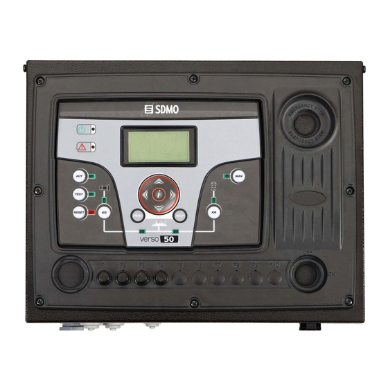
1- 7 Equipment Overview POS. NAME DESCRIPTION Backlighted display that shows all functions, measures and alarms about the generator and Display the mains. Automatically the backlight turns off, and it turns on again when you press a button. Button to select the automatic mode. TEST Button to select the test mode. -
Page 11
1- 8 Display pages 1- 8.4 Generator stats When you turn on the board, you will see the logo page. Then you will be in the stand-by page (Mains). With the left and right arrows, you can move through the different pages. 1- 8.1 Mains A) Maximum value measured on the L1 line voltage of the generator… -
Page 12
1- 8.8 I/O Monitor In this page you can see the state of the input J4.4 (EJPT) and the 3 outputs J1.2 (KR), J1.4 (KG) and J5.4 (Remote start output). 1- 8.9 Info page This page contains the contacts data of the manufacturer – web address, telephone number and address. -
Page 13
2- PROGRAMMATION MENUS 2- 1 Navigation instructions Entering global setup, pressing the MENU button, you have to insert the correct password to access to the programmation menu. The password, by default, is 809. If you enter the wrong password, you will see the indication “wrong code” and you will not be able to enter inside the menu. -
Page 14
0-100 [%] considered faulty and VERSO 50 activates the remote start output (in automatic mode). You can set a delay time for the closure of the mains contactor. This time starts from when the VERSO 50 KR delay 0-100 [s] opens… -
Page 15
“ON Alarms delay” must be at least 5 seconds higher than the preheat time set in the engine protection controller. The cooling procedure is managed by the VERSO 50. If the engine protection controller allows to set a cooling procedure, we advise to disable it and maintain active only the procedure on the VERSO 50 controller. -
Page 16
2- 4 M3 — Test setup DEFAULT POS. NAME DESCRIPTION RANGE OF VALUES SETTINGS Enable test 1 Used to enable or disable the automatic test. On-Off Test type To set the type of test. Daily-Weekly-Monthly Weekly If the type of test is chosen weekly, it permits to set the Mond., Tuesd., Wed., Day of week Thur. -
Page 17
Off-250 [s] the standby page (Mains 1) if no buttons are pressed. Contrast To set the display contrast preferred for the VERSO 50. It is the time of the cyclic indication of the active alarms. The Cyclic alarms 0-255 [s] new parameter is active at the next system startup. -
Page 18
2- 5.3 M4.3 — Security setup The security setup menu permits to enter 6 access codes the permit to lock/unlock the programmation menus. By default, the 6 access codes are set correctly, so you can access to all the menus. You have the possibility to protect the programmation menus entering wrong codes: this way the menus correspondant to the wrong codes inserted are locked. -
Page 19
2- 6 M5 — Alarms list You will see a general screen for the setup of the alarms, composed by 4 pages. In the first page, select and confirm the parameter “a” to choose the code of the alarm. In the upper part of the screen you will see the name of the correspondant alarm. Then modify the parameters from “d”… -
Page 20
Alarm relay Activation Type of stop Alarm code Alarm name 1201 Low frequency generator 1202 High frequency generator 1203 Low voltage generator … -
Page 21
0-59 [min] before the opening of KR and the closure of KG. EJPT 2 input Function disabled in the VERSO 50 with only 1 input. On/Off If ON, when EJPT mode is active (remote start input active), the No KR with EJPT mains contactor opens and it’s not possible to close it also if the… -
Page 22
3- PANELS — ELECTRICAL DRAWINGS 3-1 Single Phase — 40A VERSO 50_v1.0.27_EN.doc 33502027401_3_1 Page 20/24… -
Page 23
3- 2 Single Phase — 100A VERSO 50_v1.0.27_EN.doc 33502027401_3_1 Page 21/24… -
Page 24
3- 3 Three Phase — 25A VERSO 50_v1.0.27_EN.doc 33502027401_3_1 Page 22/24…
OVERVIEW — MAIN CHARACTERISTICS — INSTALLATION — WIRING ……………………………………………………………… 2
1- GENERAL REQUIREMENTS AND INSTALLATION …………………………………………………………………………………….. 3
1- 1 General notes …………………………………………………………………………………………………………………………………………………… 3
1- 2 Product Label and Rating plate …………………………………………………………………………………………………………………………. 3
1- 3 Hardware ratings ……………………………………………………………………………………………………………………………………………… 4
1- 4 Electrical Installations ………………………………………………………………………………………………………………………………………. 5
1- 5 Connections …………………………………………………………………………………………………………………………………………………….. 6
1- 6 Operation modes ……………………………………………………………………………………………………………………………………………… 7
1- 6.1 Automatic mode …………………………………………………………………………………………………………………………………………………………… 7
1- 6.2 Manual mode ……………………………………………………………………………………………………………………………………………………………….. 7
1- 6.3 Reset mode …………………………………………………………………………………………………………………………………………………………………. 7
1- 6.4 Test mode ……………………………………………………………………………………………………………………………………………………………………. 7
1- 6.5 Alarms ………………………………………………………………………………………………………………………………………………………………………… 7
1- 7 Equipment Overview ………………………………………………………………………………………………………………………………………… 8
1- 8 Display pages ………………………………………………………………………………………………………………………………………………….. 9
1- 8.1 Mains …………………………………………………………………………………………………………………………………………………………………………… 9
1- 8.2 Mains stats …………………………………………………………………………………………………………………………………………………………………… 9
1- 8.3 Generator …………………………………………………………………………………………………………………………………………………………………….. 9
1- 8.4 Generator stats …………………………………………………………………………………………………………………………………………………………….. 9
1- 8.5 Hours …………………………………………………………………………………………………………………………………………………………………………… 9
1- 8.6 Events log ……………………………………………………………………………………………………………………………………………………………………. 9
1- 8.7 Clock and warranty ……………………………………………………………………………………………………………………………………………………….. 9
1- 8.8 I/O Monitor ………………………………………………………………………………………………………………………………………………………………….. 10
1- 8.9 Info page …………………………………………………………………………………………………………………………………………………………………….. 10
1- 8.10 System data ………………………………………………………………………………………………………………………………………………………………. 10
1- 8.11 Logo page…………………………………………………………………………………………………………………………………………………………………. 10
2- PROGRAMMATION MENUS ……………………………………………………………………………………………………………………. 11
2- 1 Navigation instructions …………………………………………………………………………………………………………………………………… 11
2- 2 M1 — Mains setup …………………………………………………………………………………………………………………………………………….. 12
2- 3 M2 — Alternator setup ………………………………………………………………………………………………………………………………………. 13
2- 4 M3 — Test setup ………………………………………………………………………………………………………………………………………………. 14
2- 5 M4 — General setup …………………………………………………………………………………………………………………………………………. 15
2- 5.1 M4.1 — Display setup …………………………………………………………………………………………………………………………………………………… 15
2- 5.2 M4.2 — Clock setup ……………………………………………………………………………………………………………………………………………………… 15
2- 5.3 M4.3 — Security setup ………………………………………………………………………………………………………………………………………………….. 16
2- 6 M5 — Alarms list ………………………………………………………………………………………………………………………………………………. 17
2- 7 M6 — EJPT setup ……………………………………………………………………………………………………………………………………………… 19
2- 8 M7 — Counters …………………………………………………………………………………………………………………………………………………. 19
2- 9 M8 — Measures ………………………………………………………………………………………………………………………………………………… 19
3- PANELS — ELECTRICAL DRAWINGS ………………………………………………………………………………………………………. 20
3- 1 Single Phase – 40A …………………………………………………………………………………………………………………………………………. 20
3- 2 Single Phase – 100A ……………………………………………………………………………………………………………………………………….. 21
3- 3 Three Phase – 25A ………………………………………………………………………………………………………………………………………….. 22
3- 4 Three Phase – 40A ………………………………………………………………………………………………………………………………………….. 23
4- BATTERY CHARGER ……………………………………………………………………………………………………………………………… 24
VERSO 50_v1.0.27_EN
33502027401_3_1
page 1/24
Предназначен для переключения нагрузки с основной сети на аварийный генератор, при пропадании электричества или падении напряжения ниже определенного уровня. Блок АВР серии Verso 50 предназначен для электрических цепей не более 40 ампер и может работать как на всю электрическую цепь так и на отдельные ее участки необходимые для обьекта (котел отопления охранные комплексы, дежурное освещение, бытовая техника, ит.д.)
Для моделей с воздушным охлаждением напряжение 230В
Автоматический коммутатор нагрузки 40А/230В SDMO Verso 50
Описание
ОПИСАНИЕ РАБОТЫ УСТРОЙСТВА
Блок ввода резерва VERSO50 в автоматическом режиме отслеживает состояние электросети.
При отключении основного источника питания VERSO запускает резервную станцию.
После восстановления электропитания от городской сети коммутатор отключает
резервный генератор, запитывая объект от основного источника.
ВСТРОЕННЫЕ ФУНКЦИИ
Автоматические часы:
АВР VERSO50 позволяет проводить ежедневные, еженедельные, ежемесячные тесты (под нагрузкой и без),
что бы обеспечить правильное функционирование ГУ — (генераторной установки) во время
пропадания сети.
Для удаленных объектов (без сети), эта функция позволяет запускать ГУ периодически,
чтобы поддерживать заряд батареи.
Зарядное устройство:
АВР VERSO50 имеет в стандартной комплектации зарядное устройство, чтобы обеспечить
необходимый заряд батареи для запуска ГУ на объектах запитанных от основной сети.
ОСОБЕННОСТИ
АВР VERSO50 совместим только с ГУ оснащенными панелью управления MODYS.
Важно!!!
В отличии от коммутатора SDMO R05A (AT-206) генератор можно использовать мобильно,
отсоединив 4-PIN клемму АВР VERSO50.
ОБЛАСТЬ ПРИМЕНЕНИЯ
Для резервирования дачных домов и маленьких офисных зданий
СОВМЕСТИМЫЕ ГУ
| Modys стандартно установлен на ГУ: Storm S6 HM Storm S7 H Diesel 6000 E Silence Diesel 10000 E Silence Diesel 6500 TE Silence Diesel 15000 TE Silence Diesel 10000 E XL C Diesel 15000 TE XL C Diesel 20000 TE XL C Technic 10000 E АВР C Technic 15000 TE АВР C Technic 20000 TE АВР C |
Modys как доп. опция для ГУ: Technic 6500 E AVR Technic 7500 TE AVR С Diesel 6000 E XL C Diesel 6500 TE XL C |
| Контроль параметров сети с программируемыми порогами срабатывания |
| Запусе ДГ по внешней команде |
| Автоматическое тестирование под нагрузкой или без |
| Запуск ДГ по расписанию |
| Запуск/остановка генератора по уровню потребляемой мощности |
| Измерение фазных и линейных напряжений сети и генератора |
| Измерение тока нагрузки и потребляемой мощности: активной и реактивной |
| Измерение частоты сети и генератора |
| Счетчик моточасов и потребленной электроэнергии |
| Счетчики времени работы от сети и генератора |
| Часы реального времени и системный журнал на 250 событий |
| Конфигурируеые аварийные сигналы и защита |
| Удобный и понятный пользовательский интерфейс |
| Встроенная справочная система |
| Многоуровневая защита доступ |
Отзывы
Оставьте отзыв об этом товаре первым!
Покупатели, которые приобрели Автоматика запуска (АВР) 40А/230В SDMO Verso 50 , также купили
Об учете особенностей нагрузки, подключаемой к ИБП и ГУ
admin
10 октября 2016
При выборе модели источника бесперебойного питания (ИБП) и генераторной установки (ГУ) в первую очередь руководствуются суммарной мощностью компонентов защищаемой системы и необходимым временем поддержания ее в автономном состоянии.
Знание суммарной мощности компонентов системы, заявленных в паспортах подключаемых приборов, к сожалению, не дает полной информации о том, на какую…
Двойное резервирование сети
admin
10 октября 2016
Схема двойного резервирования одной
группы потребителей при помощи 2-х ДГУ SDMO аналогичной мощности.
Данная схема позволяет повысить вероятность удачного запуска ДГУ в случае аварии входной сети, что может быть не маловажным для особо ответственных потребителей. Данная схема распространяется, прежде всего, на ДГУ с пультами MICS Telys. Не требуется абсолютно никаких доработок…
- Home
- Brands
- SDMO
- Switch
- VERSO 50
- Instruction Manual
Manual for SDMO VERSO 50 Switch (24 pages)
Specifications:
|
SDMO VERSO 50: Read PDF Manual Online
Accompanying Data:
SDMO VERSO 50 Switch PDF Instruction Manual (Updated: Saturday 4th of February 2023 07:50:21 AM)
Rating: 4.6 (rated by 9 users)
Compatible devices: TU-P1284, DSR4030, MLB-E4203-28-F, PSG3036, SK81DU-3, SGE2000P, 7750, Ruby3A.
Recommended Documentation:
SDMO VERSO 50: Text of Instruction Manual
(Ocr-Read Version Summary of Contents, UPD: 04 February 2023)
-
7, VERSO 50_v1.0.27_EN 33502027401_3_1 page 5/24 1- 4 Electrical Installations Warning! Before inserting the plugs and supply the board, make sure that the connections strictly comply with the wiring diagram below. NOTE: The remote start output is …
-
2, VERSO 50_v1.0.27_EN 33502027401_3_1 page 2/24
… -
6, VERSO 50_v1.0.27_EN 33502027401_3_1 page 4/24 1- 3 Hardware ratings GENERAL CHARACTERISTICS Rated Vdc voltage 12Vdc (24Vdc) Vdc range From 7Vdc to 33Vdc Rated Vac voltage 400 Vac Vac range Up to 500 Vac Frequency range From 45 to 75 Hz Fixed consumption w…
-
11, VERSO 50_v1.0.27_EN 33502027401_3_1 page 9/24 1- 8 Display pages When you turn on the board, you will see the logo page. Then you will be in the stand-by page (Mains). With the left and right arrows, you can move through the different pages. 1- 8.1 Mains A) L1-L2 Vac…
-
13, VERSO 50_v1.0.27_EN 33502027401_3_1 page 11/24 2- PROGRAMMATION MENUS 2- 1 Navigation instructions Entering global setup, pressing the MENU button, you have to insert the correct password to access to the programmation menu. The password, by default, is 809. If you enter the wro…
-
3, VERSO 50_v1.0.27_EN 33502027401_3_1 page 1/24 Index OVERVIEW — MAIN CHARACTERISTICS — INSTALLATION — WIRING ……………………………………………………………… 2 1- GENERAL REQUIREMENTS AND INSTALLATION ………………………………………
-
21, VERSO 50_v1.0.27_EN 33502027401_3_1 page 19/24 2- 7 M6 — EJPT setup It permits to activate the remote start if the inputs J4.4 is closed to negative. In this case, after a “Start delay” time, the remote start output is activated and, when the generator is within …
-
9, VERSO 50_v1.0.27_EN 33502027401_3_1 page 7/24 1- 6 Operation modes At the power on, the VERSO 50 is in manual mode. With the buttons you can choose the functioning mode you prefer. 1- 6.1 Automatic mode Push the AUT button to select this functioning mode. There are two diff…
-
18, VERSO 50_v1.0.27_EN 33502027401_3_1 page 16/24 2- 5.3 M4.3 — Security setup The security setup menu permits to enter 6 access codes the permit to lock/unlock the programmation menus. By default, the 6 access codes are set correctly, so you can access to all the menus. You have the possibilit…
-
8, VERSO 50_v1.0.27_EN 33502027401_3_1 page 6/24 1- 5 Connections J1 – Genset AC voltage and contactors 1.1 — Mains contactor output (NC) 1.2 — Mains contactor output (NC) 1.3 — Genset contactor output (NO) 1.4 — Genset contactor output (NO) 1.5 — Genset voltage phase 1 …
-
22, 3- PANELS — ELECTRICAL DRAWINGS 3-1 Single Phase — 40A VERSO 50_v1.0.27_EN.doc 33502027401_3_1 Page 20/24
… -
17, VERSO 50_v1.0.27_EN 33502027401_3_1 page 15/24 2- 5 M4 — General setup The general setup is composed by 3 submenus: A) Display setup: Submenu that contains all the parameters settings of the screen: language, contrast, etc. B) Clock setup: Submenu with the general se…
-
5, VERSO 50_v1.0.27_EN 33502027401_3_1 page 3/24 1- GENERAL REQUIREMENTS AND INSTALLATION 1- 1 General notes WARNING! • Carefully read the manual before the installation or use. • This equipment is to be installed by qualified personnel, complying to current standards, to avoid damages or safety haza…
-
1, VERSO 50_v1.0.27_EN 33502027401_3_1 page 1/24 VERSO 50 Instructions Manual Release: 1.0.27 33502027401_3_1
… -
10, VERSO 50_v1.0.27_EN 33502027401_3_1 page 8/24 1- 7 Equipment Overview POS. NAME DESCRIPTION A Display Backlighted display that shows all functions, measures and alarms about the generator and the mains. Automatically t…
DOC-a17f9f80:
SDMO VERSO 50: Recommended Instructions
SMW958, 1100 — Laser Printer B/W, KX-B730A, HDMI CAT-5, RCTT


-
EPOEMS4 4 Port PoE Injector HubNeed more information? Visit www.4XEM.com or call 1-866-999-4XEMEPOEMS4Complies with IEEE 802.3, IEEE 802.3u, 10/100Base-TXComplies with IEEE 802.3af, 48VDC power over unused twisted-pair wires4-Port IEEE 802.3af in-line mid-span power injector boxFull power support for each POE portProtection of circuit prevents power interference from portsLED power in …
EPOEMS4 2
-
Instruction Manual Pressure Switch 61589 Illustration similar, may vary depending on model Please read and follow the operating instructions and safety information prior to initial operation. Technical changes reserved! Illustrations, functional steps and technical data may deviate insignificantly due to continuous further developments. …
61589 6
-
Dell™ PowerConnect™ 8024/8024F/M6220/M6348/M8024/M8024-k 7024/7048/7024P/7048P/7024F/7048R/7048R-RA Upgrading PowerConnect Switches from Version 2.x.x.x or 3.x.x.x or 4.x.x.x or 5.x.x.x to 5.1.9.3 Firmware Date: September 2015 …
PowerConnect 8024 24
-
McPC 10/100Operation Manual19772 Pauling• Foothill Ranch, CA 92610-2611 USATEL: (949) 465-3000 • FAX: (949) 465-3020www.imcnetworks.com© 2006 IMC Networks. All rights reserved.The information in this document is subject to change without notice. IMC Networks assumes no responsibility for anyerrors that may appear in this document. McPC 10/100 is a trademark …
iMcV-LIM 10/100 16
-
1Montáž, obsluhu a údržbu smí provádět jen osoba s odpovídající elektrotechnickou kvalifikací.Installation, service and maintenance of the electrical equipment may be carried out by anauthorized person only.ENGLISHČESKYINSTRUCTIONS FOR USE, NÁVOD K POUŽITÍSHUNT TRIPNAPĚŤOVÁ SPOUŠŤSV-LT994043a Z00OEZ s.r.o., edivská 339, 561 51 Letohrad, Czech Re …
SV-LT 4
-
EnglishGREAT BRITAIN • customer service tel: 0845 300 9799 e-mail: [email protected] internet: www.clasohlson.com/ukVer. 20140722In-Wall Smart Energy Switch ReceiverArt.no 36-5744 Model DSC18103-ZWEUPlease read theentire instruction manual before using theproduct and then save it for future reference. We reserve theright for any error …
DSC18103-ZWEU 6
-
• Single gang PIR switch• Replaces a standard light switch or dimmer• Turns off automatically• Turns on automatically• Security mode• Switches all lighting, heating and ventilation loads up to 10AGIPDC/BUser GuideCP ElectronicsBrent Crescent London NW10 7XRT: + 44 (0)333 900 0671F: + 44 (0)333 900 [email protected] …
796-2015 8
-
Cisco Nexus 9504 NX-OS Mode Switch Hardware Installation GuideFirst Published: March 24, 2014Last Modified: November 13, 2014Americas HeadquartersCisco Systems, Inc.170 West Tasman DriveSan Jose, CA 95134-1706USAhttp://www.cisco.comTel: 408 526-4000 800 553-NETS (6387)Fax: 408 527-0883 …
Nexus 9504 110
-
http://www.3com.com/Switch 7700 Installation GuideVersion 3.03C16850 7-slot Starter Kit3C16852 8-slot Starter Kit3C16870 4-slot Starter Kitand associated modulesPart No. 10014180 Document Number: DUA1685-0AA02 Published November 2004 …
7700R 70
-
Electronic 7-Day Time SwitchInstallation and User InstructionsMODEL ET1700 SeriesWith Battery CarryoverFront ViewRear ViewBATime Switch• Input Voltage: 120/208/240/277 VAC, 60 Hz• Power Consumption: 6.0 W Max.• Contact Conguration: SPST (ET1705C), DPST (ET1725C), andSPDT (ET1715C). See wiring diagrams on next page.Switch Ratings—ET1705C, ET1725C …
ET1705C 3
Additional Information:
Popular Right Now:
Operating Impressions, Questions and Answers:
Table of Contents for SDMO VERSO 50:
-
VERSO 50_v1.0.27_EN 33502027401_3_1 page 6/24 1- 5 Connections J1 – Genset AC voltage and contactors 1.1 — Mains contactor output (NC) 1.2 — Mains contactor output (NC) 1.3 — Genset contactor output (NO) 1.4 — Genset contactor output (NO) 1.5 — Genset voltage phase 1 1.6 — Genset voltage phase 2 1
-
3- PANELS — ELECTRICAL DRAWINGS 3-1 Single Phase — 40A VERSO 50_v1.0.27_EN.doc 33502027401_3_1 Page 20/24
-
VERSO 50_v1.0.27_EN 33502027401_3_1 page 9/24 1- 8 Display pages When you turn on the board, you will see the logo page. Then you will be in the stand-by page (Mains). With the left and right arrows, you can move through the different pages. 1- 8.1 Mains A) L1-L2 Vac voltage B) L2-L3 Vac voltage C) L3-L1 Vac voltage D) L1 line voltage E) L2 line voltage F) L3 line voltage G) Mains frequency
-
VERSO 50_v1.0.27_EN 33502027401_3_1 page 16/24 2- 5.3 M4.3 — Security setup The security setup menu permits to enter 6 access codes the permit to lock/unlock the programmation menus. By default, the 6 access codes are set correctly, so you can access to all the menus. You have the possibility to protect the programmation menus entering wrong codes: this way the menus correspondant to the wrong codes inserted are locked. When you want to unlock the menus
-
VERSO 50_v1.0.27_EN 33502027401_3_1 page 10/24 1- 8.8 I/O Monitor In this page you can see the state of the input J4.4 (EJPT) and the 3 outputs J1.2 (KR), J1.4 (KG) and J5.4 (Remote start output). 1- 8.9 Info page This page contains the contacts data of the manufacturer – web address, telephone number and address. 1- 8.10 System data
-
VERSO 50_v1.0.27_EN 33502027401_3_1 page 7/24 1- 6 Operation modes At the power on, the VERSO 50 is in manual mode. With the buttons you can choose the functioning mode you prefer. 1- 6.1 Automatic mode Push the AUT button to select this functioning mode. There are two different functioning logics: a) Mains failure: the remote start output (J5.4) is activated in case of mains failure (or out of limits) and is
-
VERSO 50_v1.0.27_EN 33502027401_3_1 page 2/24
-
VERSO 50_v1.0.27_EN 33502027401_3_1 page 19/24 2- 7 M6 — EJPT setup It permits to activate the remote start if the inputs J4.4 is closed to negative. In this case, after a “Start delay” time, the remote start output is activated and, when the generator is within the limits, after “KG delay” the mains contactor is opened and the generator contactor is closed. When the input is open, if the mains is prese
-
VERSO 50_v1.0.27_EN 33502027401_3_1 page 17/24 2- 6 M5 — Alarms list You will see a general screen for the setup of the alarms, composed by 4 pages. In the first page, select and confirm the parameter “a” to choose the code of the alarm. In the upper part of the screen you will see the name of the correspondant alarm. Then modify the parameters from “d” to “l” as you prefer. Return then to the first page and confirm the parameter “c�
-
VERSO 50_v1.0.27_EN 33502027401_3_1 page 3/24 1- GENERAL REQUIREMENTS AND INSTALLATION 1- 1 General notes WARNING! • Carefully read the manual before the installation or use. • This equipment is to be installed by qualified personnel, complying to current standards, to avoid damages or safety hazards. • Before any maintenance operation on the de
-
VERSO 50_v1.0.27_EN 33502027401_3_1 page 11/24 2- PROGRAMMATION MENUS 2- 1 Navigation instructions Entering global setup, pressing the MENU button, you have to insert the correct password to access to the programmation menu. The password, by default, is 809. If you enter the wrong password, you will see the indication “wrong code” and you will not be able to enter inside the menu. To change the password, see the Sec
-
VERSO 50_v1.0.27_EN 33502027401_3_1 page 8/24 1- 7 Equipment Overview POS. NAME DESCRIPTION A Display Backlighted display that shows all functions, measures and alarms about the generator and the mains. Automatically the backlight turns off, and it turns on again when you press a button. B AUT Button to select the automatic mode. C TEST Button to select the
-
3- 2 Single Phase — 100A VERSO 50_v1.0.27_EN.doc 33502027401_3_1 Page 21/24
-
VERSO 50_v1.0.27_EN 33502027401_3_1 page 18/24 Alarm code Alarm name Delay Retentive Siren Alarm relay Activation Type of stop Global alarm 1 Global KG Global KR Always enabled Disabled Enabled when running Stop with cooling Stop engine Only indication signal SMS 1 1201 Low frequency generator 5 2 1202 High frequency generator 5
-
VERSO 50_v1.0.27_EN 33502027401_3_1 page 5/24 1- 4 Electrical Installations Warning! Before inserting the plugs and supply the board, make sure that the connections strictly comply with the wiring diagram below. NOTE: The remote start output is a positive. If you want to use a negative instead of
Questions, Opinions and Exploitation Impressions:
You can ask a question, express your opinion or share our experience of SDMO VERSO 50 device using right now.
-

- Регистрация:
- 09.10.13
- Сообщения:
-
51
- Благодарности:
- 34
Lrd127
Участник
- Регистрация:
- 09.10.13
- Сообщения:
- 51
- Благодарности:
- 34
- Адрес:
- Россия
Вопрос спецам по SDMO VERSO 050Доброго времени суток, уважаемые спецы! SDMO TECHNIC 10000E с VERSO 050 стоит на «боевом дежурстве». Хочу запрограммировать автоматический переход в режим тестирования. В меню VERSO 050 этих режимов два TEST1 и TEST2. Вопросы — 1. Какой из них выбрать? 2. Чем они отличаются (судя по меню настройки они одинаковые)? 3. С какой периодичностью производить тестирование оптимально (я каждые выходные провожу на даче)? 4. Продолжительность теста ? 5. С нагрузкой или без? 6. Надо ли это делать вообще или отключать самому рубильник сети раз в неделю минут на 10?
-
- Регистрация:
- 02.04.07
- Сообщения:
-
971
- Благодарности:
- 708
Василий Сергеич
Живу здесь
- Регистрация:
- 02.04.07
- Сообщения:
- 971
- Благодарности:
- 708
- Адрес:
- Москва
@Lrd127, Все же есть в инструкциях
открываете
https://mototech.ru/benzogeneratory/technic-10000-e/
и смотрите в две инструкции:- Руководство по эксплуатации панели АРВ VERSO 50
mototech. ru/manuals/panel_apb_verso_50.pdf - Руководство по эксплуатации панели АВР VERSO 200
mototech. ru/manuals/rukovodstvo_avp_verso_200.pdf
(вложения не могу загрузить, поэтому ссыками)
TEST1 — тестирование без нагрузки
TEST2 — тестирование с нагрузкой (той что есть)Насколько я помню, рекомендуется без нагрузки 5 минут раз в месяц, под нагрузкой час раз в 6 месяцев. Точнее прочитайте в своём гарантийном талоне.
Делать надо. TEST2 делает то же что и отключение рубильника, только немного в другой последовательности:
TEST2: включить генератор, если всё ОК — переключить нагрузку.
рубильник: отключить питание сети, включить генератор, и если всё ок, то переключить нагрузку.P. S, тест лучше не программировать в автоматическом режиме, а делать в присутствии себя любимого.
-
- Регистрация:
- 09.10.13
- Сообщения:
-
51
- Благодарности:
- 34
Lrd127
Участник
- Регистрация:
- 09.10.13
- Сообщения:
- 51
- Благодарности:
- 34
- Адрес:
- Россия
@Василий Сергеич, большое спасибо за подсказку. «Насколько я помню, рекомендуется без нагрузки 5 минут раз в месяц, под нагрузкой час раз в 6 месяцев. Точнее прочитайте в своём гарантийном талоне» — не могли бы вы дать ссылку по этой рекомендации. Инструкция по VERSO в наличии и там ничего по рекомендациям нет. Гарантийный талон где-то завалялся. На сайтах поставщиков SDMO тоже ничего не нашел, равно как и от производителя тоже. Важный момент, а точной информации нет! Заранее спасибо!
-
- Регистрация:
- 02.04.07
- Сообщения:
-
971
- Благодарности:
- 708
Василий Сергеич
Живу здесь
- Регистрация:
- 02.04.07
- Сообщения:
- 971
- Благодарности:
- 708
- Адрес:
- Москва
Я не могу вам дать точную характеристику, так как не знаю, что именно прописано в вашем гарантийном талоне. Как вы знаете, некоторые поставщики меняют стандартные гарантийные талоны на свои. То что я сказал — это стандарт. Как именно указано у вас — не знаю.
-
- Регистрация:
- 09.10.13
- Сообщения:
-
51
- Благодарности:
- 34
Lrd127
Участник
- Регистрация:
- 09.10.13
- Сообщения:
- 51
- Благодарности:
- 34
- Адрес:
- Россия
Добрый день! Нашел гарантийный талон. Там прописано один раз в неделю тестировать в течении 5 минут без нагрузки и один раз в месяц в течении часа под нагрузкой. Странно, что от производителя не нашел никаких рекомендаций.
