перейти к содержанию
SENSOR BLUE WS08 Интеллектуальный гигрометр

Введение

Перед использованием продукта
- Приложение запросит фотографию и file разрешение, потому что вы можете использовать фотографии, чтобы помочь запомнить местоположение. Само приложение не записывает историю местоположений. Пользователь Android должен включить разрешение на определение местоположения, потому что Google использует BLE и GPS в одних и тех же командах. SensorBlue — это простое приложение, которому не нужны IFI или GPS.
- Датчик представляет собой точный датчик влажности и температуры MEMS. Пожалуйста, не кладите его в воду.
- Датчик определяет температуру и влажность воздуха. через отверстие спереди, пожалуйста, не закрывайте его.


Чтобы использовать продукт, выполните следующие действия.
- Отсканируйте QR-код на коробке или в руководстве, чтобы загрузить приложение.

- Включите приложение и убедитесь, что Bluetooth приложения включен.
- Снимите батарейный отсек, после чего датчик начнет работать.

- ДЛИТЕЛЬНОЕ НАЖАТИЕ для переключения единиц C/°F.

- . Нажмите «Найти, если» на экране телефона, и УМНЫЙ ГИГРОМЕТР предупредит.

- Нажмите «Добавить устройство» или «+», чтобы добавить гигрометр.
- APP собирается соединить устройство. После того, как вы нажмете кнопку на изделии, оно автоматически подключится.


- Коснитесь значка камеры, чтобы сфотографировать место, куда вы поместили датчик. Вы можете установить желаемую температуру оповещения или влажность. При подключении гигрометра к приложению. Вы можете прочитать мгновенные данные о температуре и данные о влажности.

- Для некоторых моделей с звуковым сигналом на устройстве, если температура или влажность выходят за пределы допустимого диапазона, на устройстве будет отображаться предупреждение. Если вам нужно проверить график или историю, запишите непосредственно число температуры или число влажности. Тогда вы их увидите.


FAQ
- В: Данные температуры и влажности застревают, в чем проблема?
A: Это может быть низкий заряд батареи или поломка датчика. Если вы меняете батарею, но проблема по-прежнему возникает, обратитесь к продавцу. - В: Могу ли я вывести данные истории?
О: Да, вы можете выводить данные истории в формате CSV. Вы можете использовать Excel или Google Sheet, чтобы открыть его. - В: Сколько устройств я могу добавить в приложение?
A: 100 - В: Почему я не могу получить данные в гостиной, когда кладу их в гараж?
A: Датчик использует частоту 2.4G для передачи данных. Эту частоту трудно пробить через твердую стену. То же, что и Bluetooth-наушники. - В: Почему не удается выполнить сопряжение в настройках Bluetooth?
A: Датчик использует технологию BLE. Вы должны соединить его с APP. - В: Сколько дней будет храниться история в устройстве?
A: 100 дней - В: Могут ли несколько пользователей одновременно использовать датчик?
О: Да, независимо от того, используете ли вы iPhone или Android. Вы можете подключить их одновременно, чтобы получить данные
Заявление FCC
Это оборудование было протестировано и признано соответствующим ограничениям для цифровых устройств класса B в соответствии с частью 15 правил FCC. Эти ограничения предназначены для обеспечения разумной защиты от вредных помех при установке в жилых помещениях. Это оборудование используется и может излучать радиочастотную энергию, и, если оно не установлено и не используется в соответствии с инструкциями, может создавать вредные помехи для радиосвязи. Однако нет гарантии, что помехи не возникнут в конкретной установке. Если это оборудование создает вредные помехи для радио- или телевизионного приема, что можно определить, выключив и включив оборудование, Пользователю рекомендуется попытаться устранить помехи с помощью одной или нескольких из следующих мер.
- Изменить ориентацию или местоположение приемной антенны.
- Увеличьте расстояние между оборудованием и приемником.
- Подключить оборудование к розетке в цепи, отличной от той, к которой подключен приемник.
- Обратиться за помощью к дилеру или опытному радио / ТВ технику.
Это устройство соответствует части 15 Правил FCC. Эксплуатация осуществляется при соблюдении следующих двух условий: (1) это устройство не должно создавать вредных помех, и (2) это устройство должно принимать любые получаемые помехи, включая помехи, которые могут вызвать нежелательную работу. Изменения или модификации, не одобренные явным образом стороной, ответственной за соответствие требованиям, могут привести к аннулированию права пользователя на эксплуатацию оборудования.
Технические характеристики

Документы / Ресурсы
 14:39
14:39
Подробный тест пульсометров. Выбираем альтернативу
 03:51
03:51
Обзор Пульсометра Suunto Smart Sensor, интеграция с Samsung S8
 00:54
00:54
Как подключить SUUNTO SMART SENSOR к приложению MOVESCOUNT?
 03:04
03:04
SUUNTO SMART SENSOR Unboxing HD (SS020566000)
 08:16
08:16
A Great Trick Solving your Heart-Rate Strap Problem
 12:18
12:18
Suunto Chest Heart Rate Monitor
 01:57
01:57
How to Replace Battery in Suunto Smart Sensor HR Belt
 12:18
12:18
Розыгрыш нагрудного датчика пульса SUUNTO SMART SENSOR!
ДАТЧИК
SUUNTO SMART SENSOR
РУКОВОДСТВО
ПОЛЬЗОВАТЕЛЯ

……………………………………………………..
Страница 2
- Изображение
- Текст

1 ДОБРО ПОЖАЛОВАТЬ!
Каким
бы спортом вы ни занимались, Датчик Suunto Smart Sensor —
самый
маленький датчик частоты сердечных сокращений, совместимый c
Bluetooth® Smart — измерит вашу частоту сердечных сокращений
комфортно
и точно.
При
использовании с Suunto Ambit3 Peak, Suunto Ambit3 Peak Sport
или
с приложением Suunto Movescount, Датчик Suunto Smart Sensor
может
сохранять и передавать данные вашей частоты сердечных
сокращений
.
К
Датчик Suunto Smart Sensor прилагается мягкий и удобный ремень.
Также
его можно закрепить на спортивном снаряжении Movesense.
Датчик
Suunto Smart Sensor совместим с устройствами Bluetooth®
Smart и Smart Ready.
3

2 БЕЗОПАСНОСТЬ
Варианты
предупреждений о необходимых мерах безопасности
ПРЕДУПРЕЖДЕНИЕ
: –
используется
в
связи
с
процедурой
или
ситуацией
,
которые
могут
повлечь
за
собой
тяжелые
травмы
или
смерть
.
ПРЕДОСТЕРЕЖЕНИЕ
: –
используется
в
связи
с
процедурой
или
ситуацией
,
которая
может
повлечь
повреждение
продукта
.
ПРИМЕЧАНИЕ
: –
используется
для
привлечения
внимания
к
важной
информации
.
СОВЕТ
: –
служит
для
обозначения
дополнительных
советов
по
использованию
свойств
и
функций
устройства
.
Меры
предосторожности
ПРЕДУПРЕЖДЕНИЕ
:
НЕСМОТРЯ
НА
ТО
ЧТО
НАШИ
ИЗДЕЛИЯ
СООТВЕТСТВУЮТ
ОТРАСЛЕВЫМ
СТАНДАРТАМ
,
ПРИ
КОНТАКТЕ
С
КОЖЕЙ
МОГУТ
ВОЗНИКНУТЬ
АЛЛЕРГИЧЕСКИЕ
РЕАКЦИИ
ИЛИ
РАЗДРАЖЕНИЕ
.
В
ЭТОМ
СЛУЧАЕ
НЕМЕДЛЕННО
ПРЕКРАТИТЕ
ИСПОЛЬЗОВАНИЕ
ПРИБОРА
И
ОБРАТИТЕСЬ
К
ВРАЧУ
.
4

ПРЕДУПРЕЖДЕНИЕ : ПЕРЕД НАЧАЛОМ ПРОГРАММЫ ТРЕНИРОВОК…
Страница 5
- Изображение
- Текст
ПРЕДУПРЕЖДЕНИЕ
:
ПЕРЕД
НАЧАЛОМ
ПРОГРАММЫ
ТРЕНИРОВОК
НЕОБХОДИМО
ПРОКОНСУЛЬТИРОВАТЬСЯ
С
ВРАЧОМ
.
ЧРЕЗМЕРНЫЕ
ФИЗИЧЕСКИЕ
НАГРУЗКИ
МОГУТ
ПРИВЕСТИ
К
СЕРЬЕЗНЫМ
ТРАВМАМ
.
ПРЕДУПРЕЖДЕНИЕ
:
В
СЛУЧАЕ
НАЛИЧИЯ
КАРДИОСТИМУЛЯТОРА
,
ДЕФИБРИЛЛЯТОРА
ИЛИ
ДРУГОГО
ИМПЛАНТИРОВАННОГО
УСТРОЙСТВА
,
ИСПОЛЬЗОВАНИЕ
КАРДИОПЕРЕДАТЧИКА
ДОПУСКАЕТСЯ
ТОЛЬКО
ПОД
СОБСТВЕННУЮ
ОТВЕТСТВЕННОСТЬ
.
ПЕРЕД
НАЧАЛОМ
РЕГУЛЯРНОГО
ИСПОЛЬЗОВАНИЯ
КАРДИОПЕРЕДАТЧИКА
РЕКОМЕНДУЕТСЯ
ВЫПОЛНИТЬ
ПРОВЕРКУ
НА
ФИЗИЧЕСКУЮ
НАГРУЗКУ
С
ЭТИМ
УСТРОЙСТВОМ
ПОД
НАБЛЮДЕНИЕМ
ВРАЧА
.
ЭТО
ПОЗВОЛИТ
ОБЕСПЕЧИТЬ
БЕЗОПАСНОСТЬ
И
НАДЕЖНОСТЬ
СОВМЕСТНОГО
ИСПОЛЬЗОВАНИЯ
КАРДИОСТИМУЛЯТОРА
И
КАРДИОПЕРЕДАТЧИКА
.
ТРЕНИРОВКА
МОЖЕТ
БЫТЬ
СОПРЯЖЕНА
С
РИСКОМ
,
ОСОБЕННО
ПРИ
ДЛИТЕЛЬНОМ
ОТСУТСТВИИ
ФИЗИЧЕСКОЙ
НАГРУЗКИ
.
ПРЕЖДЕ
ЧЕМ
ПРИСТУПАТЬ
К
ПРОГРАММЕ
РЕГУЛЯРНЫХ
ТРЕНИРОВОК
,
НАСТОЯТЕЛЬНО
РЕКОМЕНДУЕМ
ПРОКОНСУЛЬТИРОВАТЬСЯ
У
ВРАЧА
.
ПРЕДУПРЕЖДЕНИЕ
:
ДЛЯ
ИСПОЛЬЗОВАНИЯ
ИСКЛЮЧИТЕЛЬНО
В
РЕКРЕАЦИОННЫХ
ЦЕЛЯХ
.
5

ПРЕДОСТЕРЕЖЕНИЕ : НЕ НАНОСИТЕ НА ИЗДЕЛИЕ РАСТВОРИТЕ…
Страница 6
- Изображение
- Текст
ПРЕДОСТЕРЕЖЕНИЕ
:
НЕ
НАНОСИТЕ
НА
ИЗДЕЛИЕ
РАСТВОРИТЕЛИ
,
ПОСКОЛЬКУ
ОНИ
МОГУТ
ПОВРЕДИТЬ
ПОВЕРХНОСТЬ
.
ПРЕДОСТЕРЕЖЕНИЕ
:
НЕ
НАНОСИТЕ
НА
ИЗДЕЛИЕ
АЭРОЗОЛЬ
ОТ
НАСЕКОМЫХ
,
ПОСКОЛЬКУ
ОН
МОЖЕТ
ПОВРЕДИТЬ
ПОВЕРХНОСТЬ
.
ПРЕДОСТЕРЕЖЕНИЕ
:
С
ЦЕЛЬЮ
СОХРАНЕНИЯ
ОКРУЖАЮЩЕЙ
СРЕДЫ
НЕ
ВЫБРАСЫВАЙТЕ
ИЗДЕЛИЕ
,
А
УТИЛИЗИРУЙТЕ
ЕГО
КАК
ЭЛЕКТРОННОЕ
ОБОРУДОВАНИЕ
.
ПРЕДОСТЕРЕЖЕНИЕ
:
ВО
ИЗБЕЖАНИЕ
ПОВРЕЖДЕНИЙ
НЕ
ПОДВЕРГАЙТЕ
УДАРАМ
И
НЕ
РОНЯЙТЕ
ИЗДЕЛИЕ
.
6

3 НАЧАЛО РАБОТЫ
После
выполнения нескольких простых действий вы готовы к
использованию
Датчик Suunto Smart Sensor для получения точных
данных
об интенсивности ваших нагрузок.
3.1 Крепление нагрудного ремня
Чтобы
начать использовать Датчик Suunto Smart Sensor и ремень
кардиопередатчика
:
1. Плотно защелкните датчик в разъем ремня.
2. Отрегулируйте длину ремня.
3. Нанесите воду или гель для электродов на области крепления
электродов
ремня.
4. Наденьте ремень так, чтобы вам было удобно. Логотип Suunto
должен
быть повернут вверх.
7

1. 3. — 4.
SUUNTO
SUUNTO
SUUNTO
Ремень
включается автоматически при обнаружении сердцебиения.
СОВЕТ
:
Для
получения
наилучших
результатов
носите
ремень
под
одеждой
.
Датчик
Suunto Smart Sensor также можно использовать со спортивной
одеждой
, совместимой с Movesense, например с футболкой Movesense
и
спортивным бюстье Salomon. Просто увлажните области электродов
на
костюме и плотно защелкните датчик в разъем костюма.
3.2 Сопряжение
Чтобы
просматривать частоту сердечных сокращений, необходимо
выполнить
сопряжение (подключить Датчик Suunto Smart Sensor к
совместимому
устройству Bluetooth® Smart или Smart Ready).
8

Совместимым устройством могут быть спортивные часы Suunto и…
Страница 9
- Изображение
- Текст
Совместимым
устройством могут быть спортивные часы Suunto или
мобильные
устройства со спортивным приложением, например, Suunto
Movescount.
Процедура
сопряжения может быть различной, поэтому см. инструкции к
мобильному
приложению или спортивным часам. При сопряжении
убедитесь
, что другие устройства Bluetooth находятся на расстоянии
минимум
10 м.
Можно
сопрягать датчик с несколькими спортивными часами и
приложениями
, но активным может быть только одно подключение.
Чтобы
подключить к Suunto Ambit3 Peak или Sport:
1. Активируйте Датчик Suunto Smart Sensor, надев его и увлажнив
электроды
.
2. На часах нажмите и удерживайте кнопку [Next (Далее)], чтобы
открыть
меню параметров.
3. Найдите пункт PAIR (Сопряжение) с помощью кнопки [Light Lock
(Блок. свет)] и выберите его, нажав кнопку [Next (Далее)].
4. Найдите пункт HR belt (Ремень кардиопередатчика)с помощью
кнопки
LIGHT LOCK (Блок. свет) и выберите его, нажав кнопку NEXT
(Далее).
5. Подождите, пока часы найдут и подключат Датчик Suunto Smart
Sensor.
Чтобы
подключить к приложению Suunto Movescount:
1. Активируйте Датчик Suunto Smart Sensor, надев его и увлажнив
электроды
.
2. Включите Bluetooth в мобильном устройстве и запустите
приложение
Suunto Movescount.
9

. Следуйте инструкциям приложения для подключения Датчик Suu…
Страница 10
- Изображение
- Текст
3. Следуйте инструкциям приложения для подключения Датчик Suunto
Smart Sensor.
10

Комментарии
- Manuals
- Brands
- Digi Manuals
- Accessories
- Connect Sensor
- User manual
-
Contents
-
Table of Contents
-
Troubleshooting
-
Bookmarks
Quick Links
Digi Connect® Sensor
User Guide
Related Manuals for Digi Connect Sensor
Summary of Contents for Digi Connect Sensor
-
Page 1
Digi Connect® Sensor User Guide… -
Page 2
Information in this document is subject to change without notice and does not represent a commitment on the part of Digi International. Digi provides this document “as is,” without warranty of any kind, expressed or implied, including, but not limited to, the implied warranties of fitness or merchantability for a particular purpose. -
Page 3: Table Of Contents
Contents Digi Connect® Sensor Get started Learn about Connect Sensor product components Verify product components Connect Sensor LEDs Connect Sensor ports and buttons Wake Connect Sensor Set up a Connect Sensor Safety information Activate the SIM card Assemble Connect Sensor Install the magnet mount…
-
Page 4
Configure Remote Manager settings Configure battery life percentage alarms Battery life alarm and alarm notification Create a battery life alarm for Connect Sensor devices Configure the global battery alarm for a device Configure internal temperature settings Configure local interface settings: CLI and Bluetooth… -
Page 5
Modbus Protocol Settings option definitions Data stream definitions Group definitions for Connect Sensor data streams Connect Sensor device-specific (ts1 and ui) data stream definitions Analog input (ain and cl) data stream definitions Analog (avout), digital (dvout1), and serial power output data stream definitions… -
Page 6
Internal temperature CLI commands Modbus CLI commands Troubleshooting Connect Sensor LEDs for troubleshooting Device not responding Check the battery Reset the device Restore factory defaults to the device Device not connected to the cellular network Verify SIM configuration Check cellular antenna… -
Page 7: Digi Connect® Sensor
You can sign in to your Remote Manager account to view the reports or use the Digi Connect Wizard app on a mobile device and pair it with a nearby Connect Sensor to view real-time sensor and device data in the field.
-
Page 8: Get Started
Configure pins and protocols Configure Connect Sensor device settings Learn about Connect Sensor product components These sections include a list of Connect Sensor components, and reference information about the Connect Sensor LEDs, ports, and buttons. Verify product components Connect Sensor includes the following components:…
-
Page 9
If you have purchased Digi Bundled Services, the SIM card is activated by default. Gasket lubricant Assemble Connect Sensor. Optional accessories The following accessories are available through Digi International Inc. For more information, visit the Digi Connect Sensor product page. Component Description Cellular antenna… -
Page 10
Get started Learn about Connect Sensor product components Component Description Magnet mount accessory pack The pack includes four screws, and four magnets separated by plastic discs. See Install the magnet mount for installation instructions. CAUTION! The magnets are extremely powerful. Keep magnets separated. If they touch each other they are difficult to separate. -
Page 11: Connect Sensor Leds
Connect Sensor LEDs Connect Sensor has four LED indicators to monitor Bluetooth connection, sensor activity, cellular connection, and battery life. If Connect Sensor is powered and all LEDs are off, it is in sleep mode. Note The LED indicators only light up when you wake the device by manual intervention: pressing the Wake button on the device or using a magnet.
-
Page 12
Get started Learn about Connect Sensor product components Item Description Indicator light for the cellular network connection: Cellular Solid purple: Connect Sensor is waking. Red blinking: Searching for the cellular network. Blue: Blinking: Connected to the cellular network and attempting to communicate with Remote Manager Solid light: Successfully sent data to Remote Manager. -
Page 13: Connect Sensor Ports And Buttons
Get started Learn about Connect Sensor product components Connect Sensor ports and buttons The following figure shows the controls for setting up and configuring Connect Sensor. Item Name Description Console port Connects Connect Sensor to a computer using a USB type A to B cable for access to the command line interface (CLI).
-
Page 14: Wake Connect Sensor
Thread sensor cables through these openings into Connect Sensor. Wake Connect Sensor If Connect Sensor is powered and all LEDs are off, it is in sleep mode. You can wake the device manually, if needed. Note The LED indicators only light up when you wake the device by manual intervention: pressing the Wake button inside the device or using a magnet.
-
Page 15: Set Up A Connect Sensor
«zzz… » appears in the terminal program. If you press the Wake button or use a magnet to wake Connect Sensor during this 30-second timeout period, the LED lights will not be activated, as the device is already awake. Make sure «zzz…» appears in the terminal program before you try to wake the device.
-
Page 16: Activate The Sim Card
You are using an activated SIM card (standard size) from your cellular service provider. Activate the SIM card provided by Digi Connect Sensor has a SIM card inserted in the device by default. To use a cellular connection, you must activate the inserted SIM card.
-
Page 17: Assemble Connect Sensor
2. Call your SIM card provider to activate the SIM card. Assemble Connect Sensor This section describes how to assemble Connect Sensor. Be sure to complete these steps before wiring sensors to the I/O interface. CAUTION! This product contains a lithium metal battery. Prior to installation, the battery should be inspected for any signs of damage.
-
Page 18
Get started Set up a Connect Sensor b. Unlock the SIM card tray by gently pushing the metal bar toward the bottom of the tray. c. Open the SIM card tray by pulling the tray up from the top or right side of the tray. -
Page 19: Install The Magnet Mount
User Guide for information about Remote Manager. Install the magnet mount You can install a magnet mount on Connect Sensor so that you can securely place the device on a metal object. Make sure you have the following equipment available: Magnet mount accessory pack.
-
Page 20: Configure The Cellular Connection
Connect Sensor and you can skip this section. Connect Sensor is configured with a default APN that you need to change to register Connect Sensor on the cellular network for your cellular service provider. Use the command line interface (CLI) to initially configure the cellular connection.
-
Page 21
Connect Sensor to a computer using a USB cable. Digi recommends drivers available at www.ftdichip.com/Drivers/VCP.htm. 3. Open a terminal program on a computer and connect to Connect Sensor using the following configuration: Connection port: Connect to the COM port associated with the USB cable connected to… -
Page 22: Check The Cellular Connection
At the command prompt type set commandname where commandname is one of the settings you updated, such as apn. After setting up and configuring Connect Sensor, use the following sections in this guide to configure additional settings and remotely manage Connect Sensor:…
-
Page 23: Wire The I/O Sensors
View device and sensor data streams Configure Connect Sensor device settings Add a device to Digi Remote Manager To remotely manage Connect Sensor and get sensor data, you need to create a Remote Manager account and add your Connect Sensor device to your account. Note To serve our customers most effectively, Digi International Inc.
-
Page 24
3. Click Device Management > Devices. 4. Click Add Devices. The Add Devices dialog appears. You cannot use the Discover button to discover Connect Sensor devices automatically because the devices are not available on the local network. 5. From the Add Devices drop-down menu, select IMEI, and enter the number. -
Page 25: Technical Specifications
Associated frequencies Cellular 850 and 900 MHz bands Cellular 1800 and 1900 MHz bands Connect Sensor product specifications The following table provides a summary of general product specifications for Connect Sensor. Specifications Management Configuration Remote Manager/Local USB to Serial CLI Protocol…
-
Page 26: Cell Modem Transmit (Tx) Output Power
E2 (0.5W) EDGE, 1800/1900 MHz Class E2 (0.4W) WCDMA FDD B1, B2, B4, B5, B8 Class 3 (0.25W) LE910-NA1 LTE All Bands Class 3 (0.2W) WCDMA All Bands Class 3 (0.25W) LE910-SV1 LTE All Bands Class 3 (0.2W) Digi Connect® Sensor User Guide…
-
Page 27: Hardware
Battery life Connect Sensor uses sleep and wake modes to manage power use. The device wakes only for sensor readings and sending reports to Remote Manager. It is in sleep mode at all other times to maintain low power consumption.
-
Page 28: Battery Passivization
90 — 100% (depending on the temperature). The passivization removal process could take a week or more, if the number of times Connect Sensor wakes to take sensor readings and send reports to Remote Manager is once per day or less.
-
Page 29: Connect Sensor Hardware Replacement
Hardware Connect Sensor hardware replacement Connect Sensor hardware replacement The Connect Sensor hardware can be replaced with Connect Sensor+ hardware. Additional external device monitoring features are available with Connect Sensor+ hardware: Modbus protocol Digi Connect® Sensor User Guide…
-
Page 30: Firmware
If you want to use any of the optional features, you must upgrade from the standard Connect Sensor firmware to the firmware variant that includes those features. The firmware upgrade can happen only when Connect Sensor is awake and connected to Remote Manager.
-
Page 31: Enable Csense Continuous Monitoring
Analog 4-20mA Current Loop 4 or Analog Voltage Input 4 Digital Input When using this feature, Connect Sensor never sleeps. For best performance and ease of use it is recommended that you use an external power source rather than relying on the battery within Connect Sensor.
-
Page 32: Enable Continuous Monitoring On Analog Input
Configure the buffer time for continuous monitoring. Enable continuous monitoring on analog input Note The Connect Sensor firmware must be upgraded before continuous monitoring can be enabled on the analog or digital input. For information, see CSENSE Continuous Monitoring firmware.
-
Page 33
Select a scheduling option. See Schedule options. Note The Recurring option does not work with the Connect Sensor device. c. Click Schedule. Connect Sensor downloads and applies configuration changes the next time it connects to Remote Manager. Digi Connect® Sensor User Guide… -
Page 34: Configure Pins And Protocols
Enable and configure analog inputs Connect Sensor has four analog inputs, each of which you can configure as either a 4-20 mA current loop or a voltage input. For details about the configuration options, see Analog Current Loop Input and Voltage Input option definitions.
-
Page 35: Enable And Configure Analog Power Outputs
Enable and configure analog power outputs Note Powering sensors reduces battery life. Enable and configure the power output options when you use Connect Sensor to power the analog sensors. Each of the four analog inputs also has four corresponding power outputs to power sensors. The analog power outputs work independently—each one powers only its corresponding analog input.
-
Page 36: Enable And Configure A Digital Input
Remote Manager. Enable and configure a digital input Connect Sensor has one digital I/O pin. You can configure the pin as a digital input, pulse counter, or digital output, but not more than one I/O function simultaneously.
-
Page 37: Enable And Configure A Digital Pulse Counter
Remote Manager. Enable and configure a digital pulse counter Connect Sensor has one digital I/O pin. You can configure the pin as a digital input, pulse counter, or digital output, but not more than one I/O function simultaneously.
-
Page 38: Enable And Configure A Digital Output
Enable and configure a digital output Connect Sensor has one digital I/O pin. You can configure the pin as a digital input, pulse counter, or digital output, but not more than one I/O function simultaneously. Use Remote Manager to control a digital output level and enable an internal pull-up resistor.
-
Page 39: Enable And Configure A Digital Power Output
Enable and configure a digital power output Note Powering sensors reduces battery life. Configure the digital power output options when you use Connect Sensor to power an external device. For details about the configuration options, see Analog Power, Digital Power, and Serial Output option definitions.
-
Page 40: Enable And Configure The Modbus Protocol
Modbus Protocol Settings page in Remote Manager must exactly match the Modbus protocol settings on the external sensor device(s). The configuration includes a list of variables, which specify the locations on the Modbus device that the Connect Sensor should read to collect diagnostic information.
-
Page 41
Click Schedule. Connect Sensor downloads and applies configuration changes the next time it connects to Remote Manager. 11. If Connect Sensor is providing power to the Modbus device, you must enable the serial power output. For instructions, see Enable and configure a serial power output. -
Page 42: Enable And Configure A Serial Power Output
In the Connect Sensor configuration, you can specify a list of variable addresses for each station address. The variable addresses identify the values that should be pulled from each station device. If Connect Sensor is configured to read a variable that is unsupported by a Modbus station, no data sample is stored.
-
Page 43
A Modbus variable address includes a combination of the reading category, the logical address of the information, and the interpretation method. Together these create a variable address that can be added to a variable list in the Connect Sensor configuration. Step 1: Determine the reading category The reading category is the single digit prefix of the variable address. -
Page 44: About Analog And Digital Input Options
32-bits be interpreted as an IEEE 754 floating point value instead. To indicate this, the Connect Sensor variable address requires a suffix of either ‘f’ or ‘F’: If the 32-bit value can be represented as DCBA, where D represents the most significant byte of the…
-
Page 45: Hysteresis
8:00 and 20:00. An input value suddenly reaches its high threshold at 11:00. When Connect Sensor wakes at 11:00 to take a reading, it sends a high alarm report to Remote Manager.
-
Page 46: Custom Scaled Sensor Values
The alarm turns off when the sensor input value rises above 5 volts. Setting the hysteresis threshold to 0 (zero) causes Connect Sensor to send an alarm report every time the sensor input value exceeds a high or low alarm threshold.
-
Page 47
Note When calculating values, there must be a linear relationship between y1 and y2. If the sensor’s measurements are not linear, the calculated values will not be accurate. Digi Connect® Sensor User Guide… -
Page 48
Configure device (report) settings). Custom scaling factor: Refer to your sensor’s manufacturer specifications for this value. Custom scaled sample unit: Unit of measurement for your application. Reported measurement: Reported value in the unit of measurement for your application. Digi Connect® Sensor User Guide… -
Page 49: Oversampling
For example, oversampling is configured to discover the average value of 10 readings taken 70 milliseconds apart. Whenever Connect Sensor needs a value for that sensor, such as on a scheduled wake, it actually reads the sensor 10 times, 70 milliseconds apart, averages those results, and uses the averaged value as the sensor reading.
-
Page 50: One-Time
3. Select the Schedule Offline check box. Queue upload occurs the next time this device connects to Remote Manager. 4. Click Schedule. Recurring The Recurring option does not work with the Connect Sensor device. Digi Connect® Sensor User Guide…
-
Page 51: Configure Connect Sensor Device Settings
Configure local interface settings: CLI and Bluetooth Configure device (report) settings Note The Connect Sensor battery can operate 2 to 3 years when you follow standard operating conditions. Changes Connect Sensor device settings can affect battery life. For more information on standard operating conditions, see Battery life.
-
Page 52: Configure Remote Manager Settings
Remote Manager. Configure battery life percentage alarms Battery percentage is a measurement of the remaining life of a battery used in a Connect Sensor device. This measurement gives you a data point for monitoring the health of the battery and determining whether the battery should be replaced.
-
Page 53: Battery Life Alarm And Alarm Notification
Configure battery life percentage alarms Note If an external power source is used to power Connect Sensor and a battery is connected to the device, the battery percentage is reported in Remote Manager as 100%. Battery life alarm and alarm notification Remote Manager has two battery life alarm methods that you can configure to alert you when the battery life percentage falls below a specified threshold.
-
Page 54
Configure Connect Sensor device settings Configure battery life percentage alarms 6. In the Name field, enter a short, descriptive name for the alarm. 7. In the Description field, enter a description of what the alarm does. 8. In the Fire Conditions section, set the conditions that must be met for the alarm to fire. -
Page 55
Configure Connect Sensor device settings Configure battery life percentage alarms 9. In the Reset Conditions section, set the conditions that must be met for the alarm to automatically reset. Specifying reset conditions is optional. If you do not select the Reset Condition option, you will have to manually reset the alarm. -
Page 56
Configure Connect Sensor device settings Configure battery life percentage alarms 11. Click Create. The alarm is added to the list of alarms on the Alarms page. 12. When the alarm is fired, the alarm status is updated to Fired on the Device Management >… -
Page 57
Configure Connect Sensor device settings Configure battery life percentage alarms 5. In the Description field, enter a description of the alarm notification. 6. In the Send Email to field, enter the email address you want to receive the notification. More than one email address can be entered. -
Page 58: Configure The Global Battery Alarm For A Device
You can specify the battery life percentage threshold for a device in the Global Alarm Settings page. This feature alerts you when the battery percentage falls below the threshold. Connect Sensor sends an alarm report to Remote Manager, which you can review in the Data Services screen. See View battery information in a data stream.
-
Page 59
6. You can limit the data streams to the stream for one specific device. a. In the search field, enter the Connect Sensor device ID, appended by /ts1/bat, /ts1/abt, or /ts1/abt/alm. b. Click the magnifying glass icon. The specified data streams appear. -
Page 60: Configure Internal Temperature Settings
Click Schedule. Connect Sensor downloads and applies configuration changes the next time it connects to Remote Manager. Configure local interface settings: CLI and Bluetooth Enable or disable the CLI or Bluetooth for Connect Sensor through the Local Interface Settings option. For details about these options, see Local Interface Settings option definitions.
-
Page 61: Configure Device (Report) Settings
Use the Device Settings options in Remote Manager to configure Connect Sensor reporting. Together, these options control how often Connect Sensor captures data, how often data is reported, and how much data is included when it is sent to Remote Manager.
-
Page 62
Select a scheduling option. See Schedule options. Note The Recurring option does not work with the Connect Sensor device. c. Click Schedule. Connect Sensor downloads and applies configuration changes the next time it connects to Remote Manager. Digi Connect® Sensor User Guide… -
Page 63: View Device Information
The battery percentage, connection history, mobile and cellular connection details, UTC time, and firmware versions are available in the System Information menu in Remote Manager. This information is available from the last time Connect Sensor reported to Remote Manager. Note For more information about Remote Manager, visit www.digi.com/products/cloud/digi-remote-…
-
Page 64: View Battery Life For A Device In Remote Manager
Manager. 2. Click Device Management > Devices. 3. Double-click the Connect Sensor device you want to review. 4. Select System Information > Battery Percentage to view the percentage of battery power remaining. If the remaining percentage is low, you should change the battery. For instructions, Battery replacement.
-
Page 65: View Device And Sensor Data Streams
View device and sensor data streams You can use either Remote Manager or the Digi Connect Wizard mobile app to view device and sensor data streams. Remote Manager: View the most recently reported information and historical details about device or sensor data in a table, graph, or raw data format.
-
Page 66: View Device Data Streams
The following images show how these two data streams appear in Remote Manager: Additional information To learn more about: Data stream groups and group-specific short names for Connect Sensor, see Data stream definitions. General information for Remote Manager data streams, see the…
-
Page 67: Use The Mobile App To View Sensor Data Streams
Use the mobile app to view sensor data streams Connect Sensor connects to the Digi Connect Wizard mobile app using Bluetooth Smart (low energy). The Digi Connect Wizard mobile app allows you to view real-time sensor data on a nearby mobile device.
-
Page 68
7. Tap a sensor name to see real-time data. Data points load at 5-second intervals. Connect Sensor goes into sleep mode when you close the app. If you keep the app open, Connect Sensor remains awake and takes sensor readings. The device goes into sleep mode after 60 minutes. -
Page 69: Connect Sensor Maintenance
Firmware updates You can use either the CLI or Remote Manager to update the Connect Sensor device firmware, reload the current firmware, install optional firmware, or downgrade to a previous version of the firmware. Update the firmware using Remote Manager Use Remote Manager to remotely update Connect Sensor firmware.
-
Page 70: Update Firmware From Connect Sensor
Firmware updates Update firmware from Connect Sensor If you need to update the firmware before a scheduled push from Connect Sensor, you can physically wake Connect Sensor to force a connection between Connect Sensor and Remote Manager. 1. Schedule the firmware upgrade for the device in Remote Manager. For instructions, see Update the firmware using Remote Manager.
-
Page 71
Connect Sensor maintenance Firmware updates Open a terminal program on a computer and connect to Connect Sensor using the following configuration: Connection port: Connect to the COM port associated with the USB cable connected to Connect Sensor Baud rate or bits per second: 115200… -
Page 72: Battery Replacement
4. Place the new battery in the battery holder and connect the wiring to the battery port. Make sure the battery and its wiring are properly placed. 5. Press the Wake button and wait for the battery LED to slowly blink blue five times and then remain off. 6. Reassemble the device. Digi Connect® Sensor User Guide…
-
Page 73: Remote Manager Option Definitions For Connect Sensor
Remote Manager option definitions for Connect Sensor The following tables provide definitions for Remote Manager user interface options and data streams for Connect Sensor devices. Digi Connect® Sensor User Guide…
-
Page 74: Analog Current Loop Input And Voltage Input Option Definitions
Analog Current Loop Input and Voltage Input option definitions The following table provides Remote Manager definitions for Connect Sensor Analog: 4-20mA Current Loop and Analog: Voltage Input options. For additional information about using these options, see Enable and configure analog inputs.
-
Page 75
Range Option Description Default Specifies the input value to keep an alarm on or shut off an Current loop: 1.0 mA Hysteresis Current loop: 4.0 — 22 (mA) Voltage: 1.0 volts alarm during high and low alarm states. Voltage: 0.0 — 10.5 (volts) 0 —… -
Page 76
Range Option Description Default Oversampling The number of samples that should be taken. 2 — 100 Number Samples (ovn) -
Page 77: Analog Power, Digital Power, And Serial Output Option Definitions
Analog Power, Digital Power, and Serial Output option definitions The following table provides Remote Manager definitions for Connect Sensor Analog: Power Output and Digital: Power Output options. For details about setting these options, see: Enable and configure analog power outputs…
-
Page 78: Cellular Option Definitions
Cellular option definitions The following table provides Remote Manager cellular setting options for Connect Sensor. For additional information about using these options, see Configure cellular options. Option Description Identifies the access point name that connects your device to the correct cellular network.
-
Page 79: Device (Report) Settings Option Definitions
Do not make changes to this setting without help from Digi Technical Support. Device (report) settings option definitions The following table provides Remote Manager device (report) setting options for Connect Sensor. For details about setting these options, see Configure device (report) settings.
-
Page 80
For example, you have four sensors and set Send Last to 5. With these settings, Connect Sensor sends up to 20 sensor values in one report, which includes up to five of the most recent sensor values for each of the four sensors. The actual number of sensor values included in a report depends on how often Connect Sensor wakes and sends a report. -
Page 81: Digital Input Option Definitions
Digital Input option definitions The following table provides Remote Manager definitions for Connect Sensor Digital: Input options. For details about setting these options, see Enable and configure a digital input. Range Default Option Description Interface Enables or disables the digital input source.
-
Page 82: Digital Output Option Definitions
Digital Output option definitions The following table provides Remote Manager definitions for Connect Sensor Digital: Output options. For details about setting these options, see Enable and configure a digital output. Range Option Description Default Interface Enables or disables the digital output source.
-
Page 83
Alarms are only evaluated as sensors are read, and the interval between readings can be significant, even with a device using Continuous Monitoring firmware. Note that a reading may be delayed if the device is communicating with the Digi Remote Manager. For this reason, this feature… -
Page 84: Digital Pulse Counter Option Definitions
Digital Pulse Counter option definitions The following table provides Remote Manager definitions for Connect Sensor Digital: Pulse Counter options. For additional information about using these options, see Enable and configure a digital pulse counter. Range Option Description Default Interface Enable Enables or disables the digital input source.
-
Page 85: Global Alarm Settings Option Definitions
Global Alarm Settings option definitions The following table provides Remote Manager global alarm options for Connect Sensor. For additional information about using these options, see Configure the global battery alarm for a device. Range Default Option Description Battery Life Specifies the battery life percentage that generates a low battery alarm report.
-
Page 86: Internal Temperature Option Definitions
The following table provides Remote Manager internal temperature monitoring options for Connect Sensor. For additional information about using these options, see Configure internal temperature settings. CAUTION! If Connect Sensor sends reports less than 15 minutes apart, it may result in an internal temperature that is above the ambient temperature. Range Option…
-
Page 87: Local Interface Settings Option Definitions
Local Interface Settings option definitions The following table provides Remote Manager CLI and Bluetooth options for Connect Sensor. For additional information about using these options, see Configure local interface settings: CLI and Bluetooth. Range Default Option Description CLI Enable Enables or disables the command line interface (CLI) for local changes to the device.
-
Page 88
Range Option Description Default 600 — Serial baud bits The baud rate. 19200 230400 (fixed values within this range) Serial data bits The number of data bits that can be sent in a packet. Serial stop bits The bit that marks the end of a unit transition. none Serial parity The check bit for detecting an error in transmission. -
Page 89
Range Option Description Default Station 3: Variable List List of variable addresses on the specified station that you want to blank monitor. The items in the list must be separated by a comma without characters spaces. The list is limited to 63 characters, which allows for 8 to 10 variables in a list. -
Page 90: Data Stream Definitions
Data stream definitions The following sections provide Remote Manager data streams descriptions for Connect Sensor. For additional information about using data streams to analyze Connect Sensor data, see Use Remote Manager to view device and sensor data streams. Group definitions for Connect Sensor data streams The following table provides data stream group definitions for Connect Sensor.
-
Page 91: Connect Sensor Device-Specific (Ts1 And Ui) Data Stream Definitions
Connect Sensor device-specific (ts1 and ui) data stream definitions The following table provides data streams definitions for the Connect Sensor device (ts1 and ui). For additional information about data streams, refer to the following: Use data streams to analyze Connect Sensor data, see About data streams.
-
Page 92: Analog Input (Ain And Cl) Data Stream Definitions
Read period When using sdpd, the device follows the First Daily Report At HHMM (sst) (days) setting. TLS/SSL data encryption for the Connect Sensor connection to Remote TLS/SSL data Manager: encryption 0 — TLS/SSL data encryption off 1 — TLS/SSL data encryption on…
-
Page 93: Analog (Avout), Digital (Dvout1), And Serial Power Output Data Stream Definitions
The following table provides data stream definitions for the analog power output (avout 1 — 4), digital power output (dvout1), and serial power output groups for Connect Sensor. For additional information about data streams, refer to the following:…
-
Page 94: Digital Input (Din1) Data Stream Definitions
3 — 24 volts Read delay Time in seconds that the sensor voltage is enabled before Connect Sensor reads its value. This allows the sensor to stabilize to get an accurate reading. Digital input (din1) data stream definitions The following table provides data stream definitions for the digital input (din1) group for Connect Sensor.
-
Page 95: Digital Output (Dout1) Data Stream Definitions
The following table provides data stream definitions for the digital output (dout1) group for Connect Sensor. For additional information about data streams, refer to the following: Use data streams to analyze Connect Sensor data, see About data streams. Data streams group definitions, see Group definitions for Connect Sensor data streams.
-
Page 96: Digital Pulse Counter (Pcnt1) Data Stream Definitions
The following table provides data stream definitions for the digital pulse counter (pcnt1) group for Connect Sensor. For additional information about data streams, refer to the following: Use data streams to analyze Connect Sensor data, see About data streams. Data streams group definitions, see Group definitions for Connect Sensor data streams.
-
Page 97: Modbus (Modb1) Data Stream Definitions
Data stream definitions Modbus (modb1) data stream definitions CAUTION! If Connect Sensor sends reports less than 15 minutes apart, it may result in an internal temperature that is above the ambient temperature. For additional information about data streams, refer to the following:…
-
Page 98
Coils and discrete inputs will be 0 or 1. Variable that returns a Input and holding registers will be 16-bit unsigned integer value values, or signed floating point values, depending on configuration. vars<1-4> Corresponding Modbus Comma-separated list of variable addresses. variable list Digi Connect® Sensor User Guide… -
Page 99: Data Streams For Modbus Protocol
Modbus (modb1) data stream definitions Data streams for Modbus protocol Item Name Description Connect Sensor device ID Identifies the device. Identifies the device-specific function or sensor for the data Group stream. For example, modb1 corresponds to the sensor for a device with Modbus protocol enabled.
-
Page 100: Use The Cli With Connect Sensor
Connect Sensor status information. To use CLI commands, you must connect a USB cable from a computer to Connect Sensor, and then open a terminal program in the computer. You can enter CLI commands in the terminal program:…
-
Page 101
Parity: None Stop: 1 bit Flow control: None 5. Press the Wake button on Connect Sensor and wait 5-10 seconds after the cellular LED starts blinking. 6. Type your CLI command and press Enter. fwupdate: Update the firmware on the device. See Update the firmware using the CLI. -
Page 102: Use The Cli To View Status Information For The Device
View battery life using the CLI. Verify cellular network coverage using the CLI If you have physical access to Connect Sensor, you can use the CLI to verify the cellular signal strength using the CLI status command. 1. On your laptop, go to www.digi.com/support…
-
Page 103: View Battery Life Using The Cli
Use the CLI with Connect Sensor View battery life using the CLI View battery life using the CLI You can check the battery life using the CLI. Note You can also check battery life using Remote Manager. See View battery life for a device in Remote Manager.
-
Page 104: Cli Commands
CLI commands The following sections provide all of the available CLI commands for configuring Connect Sensor and viewing status information. fwupdate status Digi Connect® Sensor User Guide…
-
Page 105: Fwupdate
The status information represents a snapshot in time, and is updated each time you type the status command. The Connect Sensor device modem must be connected to the cellular network to be able to capture and display cellular information for the device. The modem is awake for a short amount of time and then automatically disconnects from the network.
-
Page 106: Set
Number of times cellular modem was reset to recover from errors since power up. Type set and additional commands at the command prompt to configure device and sensor settings. Options See the commands in the following sections. Digi Connect® Sensor User Guide…
-
Page 107: Analog Input Cli Commands
Analog input CLI commands Use set, the sensor identifier, and the commands in the following table to configure sensor options with the CLI. For example, type set ain1 ena=on at the command prompt to enable the analog voltage input 1 interface. Sensor identifiers: Analog voltage input 1: ain1 Analog voltage input 2: ain2…
-
Page 108
Value options Option command Description Default Enables or disables alarm reports for the Empty (all alarms disabled) Alarms analog input sources. When enabled, sends an alarm report in one of the following conditions: High alarm Low alarm Enable multiple alarms using a Delta high alarm comma separated command Delta low alarm… -
Page 109
Value options Option command Description Default Specifies the input value to keep an alarm Hysteresis Current loop: 4.0 — 22 (mA) Current loop: 1.0 on or shut off an alarm during high and low Voltage: 0.0 — 10.5 (volts) Voltage: 1.0 alarm states. -
Page 110: Digital Input Cli Commands
Digital input CLI commands Use the commands in the following table with the set command and din1 when configuring the digital input options with the CLI. For example, type set din1 ena=on to enable the digital input interface. Value options Option command Description…
-
Page 111
Value options Option command Description Default Enables or disables the device to monitor a Rising and Empty (all edge wake rise digital input during sleep mode as follows falling edge alarms off) fall (they are either all On or all Off when using wake the CLI for configuration): Enable both alarms using a comma… -
Page 112: Digital Output Cli Commands
Digital output CLI commands Use the commands in the following table with the set command and dout1 when configuring the digital output options with the CLI. For example, type set dout1 ena=on to enable the digital output interface. Value options Option commands Description…
-
Page 113: Digital Pulse Counter Cli Commands
Digital pulse counter CLI commands Use the commands in the following table with the set command and pcnt1 when configuring the digital pulse counter options with the CLI. For example, type set pcnt1 ena=on to configure the digital pulse counter interface. Value options Option command…
-
Page 114
Value options Option command Description Default Enable pullup puen Enables or disables the internal pull-up resistor to drive a logic level voltage. Sensor Specifies description of the sensor for the pulse Text Empty description counter. Custom scaled unit Specifies the unit of measurement the pulse Text Empty sample unit… -
Page 115: Analog And Digital Power Output Cli Commands
Specifies the time in seconds that the sensor voltage is enabled before Read delay 0-120 seconds Connect Sensor reads its value. This allows the sensor to stabilize to get an accurate reading. Note A higher read delay keeps the device powered on longer, which…
-
Page 116: Cellular Cli Commands
Option command Description Value options Identifies the access point name that If you purchased Digi Bundled Services, connects your device to the correct cellular this value is preconfigured for you. network. If you purchased cellular service through a third party, contact your provider for this value.
-
Page 117
Option command Description Value options Password Specifies the password for your cellular Use only when required by your network account. cellular service provider. Length: Up to 63 characters Printable characters and spaces only (no quotation marks or backslashes) No value: disabled (no password required) SIM PIN Specifies the PIN for your cellular network… -
Page 118: Remote Manager Cli Commands
Use the following commands with the set command when configuring the device with the CLI. All Remote Manager configuration values are preconfigured. supplied by your cellular service provider. Do not make changes to this setting without help from Digi Technical Support.
-
Page 119: Internal Temperature Cli Commands
Internal temperature CLI commands Use the following command with the set command when configuring the device with the CLI. CAUTION! If Connect Sensor sends reports less than 15 minutes apart, it may result in an internal temperature that is above the ambient temperature.
-
Page 120
Value options Option commands Description Default Specifies the degrees in Celsius to keep an alarm on or Hysteresis 0 to 100 shut off an alarm during high and low alarm states. 0 — Hysteresis is off 1 or more — Hysteresis is on and managing alarms… -
Page 121: Modbus Cli Commands
Use the commands in the following table with the set command and modb1 when configuring the digital input options with the CLI. For example, type set modb1 ena=on to enable the Modbus protocol for the external sensor device. Note The Modbus protocol is available only with Connect Sensor+ hardware. Value options Option…
-
Page 122: Troubleshooting
Use the four LEDs on Connect Sensor when troubleshooting the device. These LEDs have specific behaviors that provide information for Bluetooth connection, sensor activity, cellular connection, and battery life. If Connect Sensor is powered and all LEDs are off, it is in sleep mode. See Connect Sensor LEDs for detailed information about the LEDs.
-
Page 123: Restore Factory Defaults To The Device
Use this procedure when the device is still not responding after pressing the Reset button. 1. With the Connect Sensor enclosure open, press and hold the Factory button for at least 3 seconds until the LEDs flash purple. The device is reset to its factory defaults.
-
Page 124: Check Battery Life
2. Sign in to Remote Manager. 3. Verify that the 15-digit device IMEI number on the Connect Sensor label is the same as the Device ID in Remote Manager. 4. Add your device to Remote Manager if the numbers do not match: a.
-
Page 125: Reset The Device
Use the mobile app to view sensor data streams. Reset the device If your Connect Sensor still does not appear in the mobile app after verifying Bluetooth settings, try resetting the device. 1. Open Connect Sensor enclosure. 2. Press and release the Reset button.
-
Page 126: Regulatory Information
FCC ID. Modifications (FCC 15.21) Changes or modifications to this equipment not expressly approved by Digi may void the user’s authority to operate this equipment. Declaration of Conformity (DoC) Digi has issued Declarations of Conformity for the Connect Sensor concerning emissions, EMC, and safety.
-
Page 127: Ce Mark (Europe)
The Connect Sensor is certified for use in several European countries. For information, visit www.digi.com/resources/certifications. If the Connect Sensor is incorporated into a product, the manufacturer must ensure compliance of the final product with articles 3.1a and 3.1b of the RE Directive (Radio Equipment Directive). A Declaration of Conformity must be issued for each of these standards and kept on file as described in the RE Directive (Radio Equipment Directive).
-
Page 128: Safety Notices
However, cellular-based products contain radio devices that require specific consideration. Make sure you read and understand all of the safety notices, warnings, and cautions for this product. Digi International assumes no liability for failure to comply with these precautions.
-
Page 129: Installation Considerations
Connect Sensor must be installed in an enclosure that provides a degree of protection not less than IP54, in accordance with EN 60079-15. Connect Sensor should be used in an area of not more than pollution degree 2, as defined in EN 60664-1.
-
Page 130: Warnings: Explosion Hazards
Note The Connect Sensor device contains internal batteries. WARNING! Connect Sensor is suitable for use in UL/cUL Class I, Division 2, Groups A, B, C, and D hazardous locations or non-hazardous locations only. Substitution of any component may impair suitability for Class I, Division 2.
-
Page 131: Rf Exposure Statement
Connect Sensor must be installed in an enclosure that provides a degree of protection not less than IP54, in accordance with EN 60079-15. Connect Sensor should be used in an area of not more than pollution degree 2, as defined in EN 60664-1.
-
Page 132: Atex Marking
The battery should be replaced in unclassified areas only. WARNING! Install Connect Sensor in an area that does not have more than pollution degree 2 as defined in EN/ IEC 60664-1. WARNING! To avoid potentially dangerous electrostatic discharges, control all likely ignition sources, minimize the harmful effects of any accidental fire or explosion by using explosion relief and suppression systems.
-
Page 133
“enhanced” level of protection, which is not a source of ignition in normal operation and which may have some additional protection to ensure that it remains inactive as an ignition source in the case of regular expected occurrences (for example, failure of a lamp). Digi Connect® Sensor User Guide…
DOC023.98.80088
Chlorine Sensor
02/2018, Edition 9
User Manual
Bedienungsanleitung
Manuale utente
Manuel de l’utilisateur
Manual del usuario
Manual do utilizador
Návod k použití
Brugervejledning
Gebruikershandleiding
Instrukcja obsługi
Bruksanvisning
Ръководство за потребителя
Felhasználói kézikönyv
Manual de utilizare
Руководство пользователя
Kullanıcı Kılavuzu
Návod na použitie
Navodila za uporabo
Korisnički priručnik
Εγχειρίδιο χρήσης

English……………………………………………………………………………………………………………………………………………………………………………3
Deutsch………………………………………………………………………………………………………………………………………………………………………..23
Italiano…………………………………………………………………………………………………………………………………………………………………………. 46
Français………………………………………………………………………………………………………………………………………………………………………. 68
Español……………………………………………………………………………………………………………………………………………………………………….. 90
Português…………………………………………………………………………………………………………………………………………………………………. 112
Čeština………………………………………………………………………………………………………………………………………………………………………. 134
Dansk………………………………………………………………………………………………………………………………………………………………………….155
Nederlands……………………………………………………………………………………………………………………………………………………………….. 176
Polski…………………………………………………………………………………………………………………………………………………………………………. 198
Svenska…………………………………………………………………………………………………………………………………………………………………….. 220
български………………………………………………………………………………………………………………………………………………………………… 241
Magyar………………………………………………………………………………………………………………………………………………………………………. 265
Română…………………………………………………………………………………………………………………………………………………………………….. 286
Русский…………………………………………………………………………………………………………………………………………………………………….. 308
Türkçe…………………………………………………………………………………………………………………………………………………………………………332
Slovenský jazyk………………………………………………………………………………………………………………………………………………………. 353
Slovenski…………………………………………………………………………………………………………………………………………………………………… 374
Hrvatski……………………………………………………………………………………………………………………………………………………………………… 395
Ελληνικά……………………………………………………………………………………………………………………………………………………………………. 416
2
Table of contents
Specifications on page 3 Maintenance on page 16
General information on page 4 Troubleshooting on page 20
Installation on page 6 Replacement parts on page 22
Operation on page 10
Specifications
Specifications are subject to change without notice.
Specification Details
Measurement range 0 to 20 ppm
1
Lower limit of detection 30 ppb (0.030 ppm)
Resolution 0.001 ppm (1 ppb)
pH operating range 4 to 9 pH units
Accuracy
(chlorine concentrations
within ±2 ppm or 20%
(whichever is smaller) of the
calibrated point)
Free chlorine (0 to 10 ppm):
• ± 3% of the reference test
2
(DPD) at constant
pH less than 7.2 (±0.2 pH unit)
• ± 10% of the reference test
2
(DPD) at stable
pH less than 8.5 (±0.5 pH unit from the pH at
chlorine calibration)
Total chlorine (0 to 10 ppm):
• ± 10% of the reference test
2
(DPD) at stable
pH less than 8.5 (±0.5 pH unit from the pH at
chlorine calibration)
• ± 20% of the reference test
2
(DPD) at pH
greater than 8.5
Specification Details
Repeatability 30 ppb or 3%, whichever is greater
Response time Free chlorine: 140 seconds for 90% change (T
90
)
at a stable temperature and pH
Total chlorine: 100 seconds for 90% change (T
90
)
at a stable temperature and pH
Sampling time Continuous
Interferences Free chlorine: Monochloramine, chlorine dioxide,
ozone and chalk deposits
Total chlorine: Chlorine dioxide, ozone and chalk
deposits
Pressure limit 0.5 bar, no pressure impulses and/or vibrations
Flow rate 30 to 50 L/hour (7.9 to 13.2 gal/hour)
40 L/hour (10.5 gal/hour) – optimal
Power requirements 12 VDC, 30 mA maximum (supplied by controller)
Operating temperature 5 to 45 °C (41 to 113 °F)
Storage temperature Sensor: 0 to 50 °C (32 to 122 °F) dry without
electrolyte
Electrolyte: 15 to 25 °C (59 to 77 °F)
Dimensions
(length/diameter)
195 mm (7.68 in.)/25 mm (0.98 in.)
Cable length/type 1 m
Cable connection 5 pin, M12 connector
Measurement method Reagentless, electrochemical, amperometric,
three-electrode system
Calibration methods 1-point or 2-point (zero and slope) calibration
Temperature compensation Internal temperature sensor
1
The chlorine sensors are not applicable for applications with consistently low (< 0.1 ppm) or zero chlorine concentrations.
2
The test must be conducted at the analyzer sampling point.
English 3
Specification Details
Material Corrosion-resistant materials (stainless steel,
PVC, silicon rubber and polycarbonate)
Warranty 1 year warranty on the electrode body, includes
the electronics (EU: 2 years)
General information
In no event will the manufacturer be liable for direct, indirect, special,
incidental or consequential damages resulting from any defect or
omission in this manual. The manufacturer reserves the right to make
changes in this manual and the products it describes at any time, without
notice or obligation. Revised editions are found on the manufacturer’s
website.
Safety information
N O T I C E
The manufacturer is not responsible for any damages due to misapplication or
misuse of this product including, without limitation, direct, incidental and
consequential damages, and disclaims such damages to the full extent permitted
under applicable law. The user is solely responsible to identify critical application
risks and install appropriate mechanisms to protect processes during a possible
equipment malfunction.
Please read this entire manual before unpacking, setting up or operating
this equipment. Pay attention to all danger and caution statements.
Failure to do so could result in serious injury to the operator or damage
to the equipment.
Make sure that the protection provided by this equipment is not impaired.
Do not use or install this equipment in any manner other than that
specified in this manual.
Use of hazard information
D A N G E R
Indicates a potentially or imminently hazardous situation which, if not avoided, will
result in death or serious injury.
W A R N I N G
Indicates a potentially or imminently hazardous situation which, if not avoided,
could result in death or serious injury.
C A U T I O N
Indicates a potentially hazardous situation that may result in minor or moderate
injury.
N O T I C E
Indicates a situation which, if not avoided, may cause damage to the instrument.
Information that requires special emphasis.
Precautionary labels
Read all labels and tags attached to the instrument. Personal injury or
damage to the instrument could occur if not observed. A symbol on the
instrument is referenced in the manual with a precautionary statement.
This is the safety alert symbol. Obey all safety messages that follow
this symbol to avoid potential injury. If on the instrument, refer to the
instruction manual for operation or safety information.
This symbol indicates that a risk of electrical shock and/or
electrocution exists.
This symbol indicates the presence of devices sensitive to Electro-
static Discharge (ESD) and indicates that care must be taken to
prevent damage with the equipment.
Electrical equipment marked with this symbol may not be disposed of
in European domestic or public disposal systems. Return old or end-
of-life equipment to the manufacturer for disposal at no charge to the
user.
Product overview
The free chlorine sensor and total chlorine sensor are reagentless,
electrochemical sensors that continuously measure the chlorine
4
English
concentration in water. The free chlorine sensor measures the
concentration of free chlorine (generated from inorganic chlorine
products) in water. The total chlorine sensor measures the concentration
of total chlorine (free chlorine and combined chlorine) in water.
Variations in the pH value have an affect on the accuracy of the chlorine
measurement. The chlorine value shown on the controller usually
decreases at about 10% per pH unit increase.
This sensor has an internal temperature sensor that increases the
accuracy of chlorine measurement. The temperature measurement
signal is used internally by the sensor for automatic temperature
compensation. The temperature measurement signalis not shown on the
controller.
This sensor is designed to work with the digital gateway for the CLF10sc
and CLT10sc Reagentless Chlorine Analyzer and one of the sc series
controllers for data collection and operation.
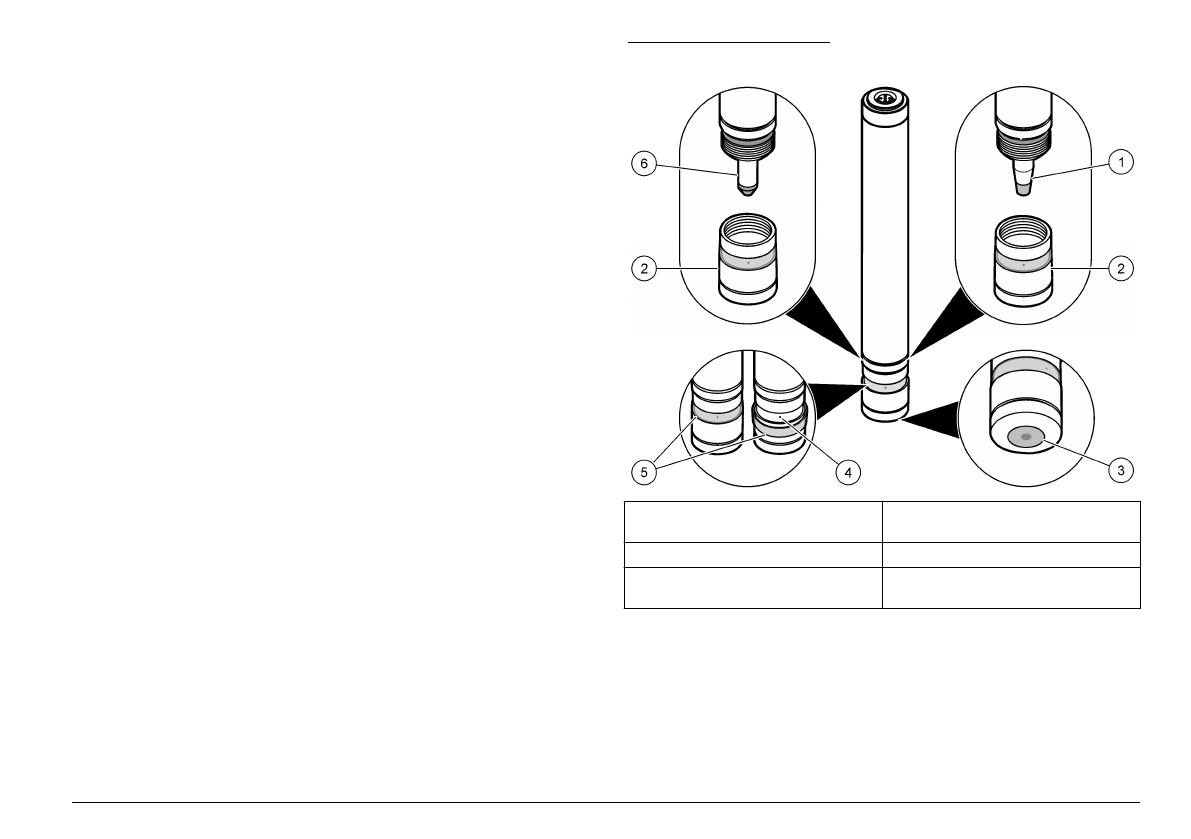
Figure 1 shows the free chlorine sensor and total chlorine sensor.
Figure 1 Sensor overview
1 Electrode of the free chlorine
sensor
4 Vent hole in membrane cap
2 Membrane cap 5 Rubber band
3 Membrane 6 Electrode of the total chlorine
sensor
Sensor LEDs
The green LED and orange LED located inside the transparent area of
the chlorine sensor indicate the conditions of the power supply, sensor
signal polarity and electrochemical cell.
English
5
LED color Condition Description
Green On (steady) The processor is working correctly.
Off or On
(flashing)
The voltage is too low which has caused a
malfunction of the processor.
Orange Off The sensor is working correctly.
On (steady) The internal signal from the working electrode
has the wrong polarity.
If the LED is on for longer than 30 minutes, do
sensor maintenance.
On (flashing) The level of chlorine concentration is too high.
Reduce the chlorine concentration.
Theory of operation
This sensor is a potentiostatic three-electrode instrument, with a
specially placed counter electrode. The measuring (working) electrode is
membrane covered and is in the electrolyte together with the reference
electrode. This electrode area contains a special electrolyte and is
separated from the measured sample by the membrane.
The sensor uses an amperometric method to measure chlorine
concentration in water. Chlorine species in the measured sample pass
through the membrane and react with the working electrode. This
reaction produces an electrical current proportional to the chlorine
concentration. The electrical signal is amplified by the sensor electronics
and is transmitted to the instrument in voltage format (mV). The third
electrode (auxiliary or counter electrode) is put in the measured sample
and is used to maintain a constant working potential on the working
electrode. The working potential is controlled by the reference electrode.
This configuration increases measurement stability.
The highly-buffered electrolyte inside the membrane cap supplies
internal compensation for pH fluctuations in the measured sample. The
buffer helps to immediately change hypochlorite ions permeating the
membrane into hypochlorous acid molecules. The electrolyte makes the
measurement almost independent of the pH of the measured sample.
The chlorine readings are independent from the temperature of the
measured water due to internal temperature compensation.
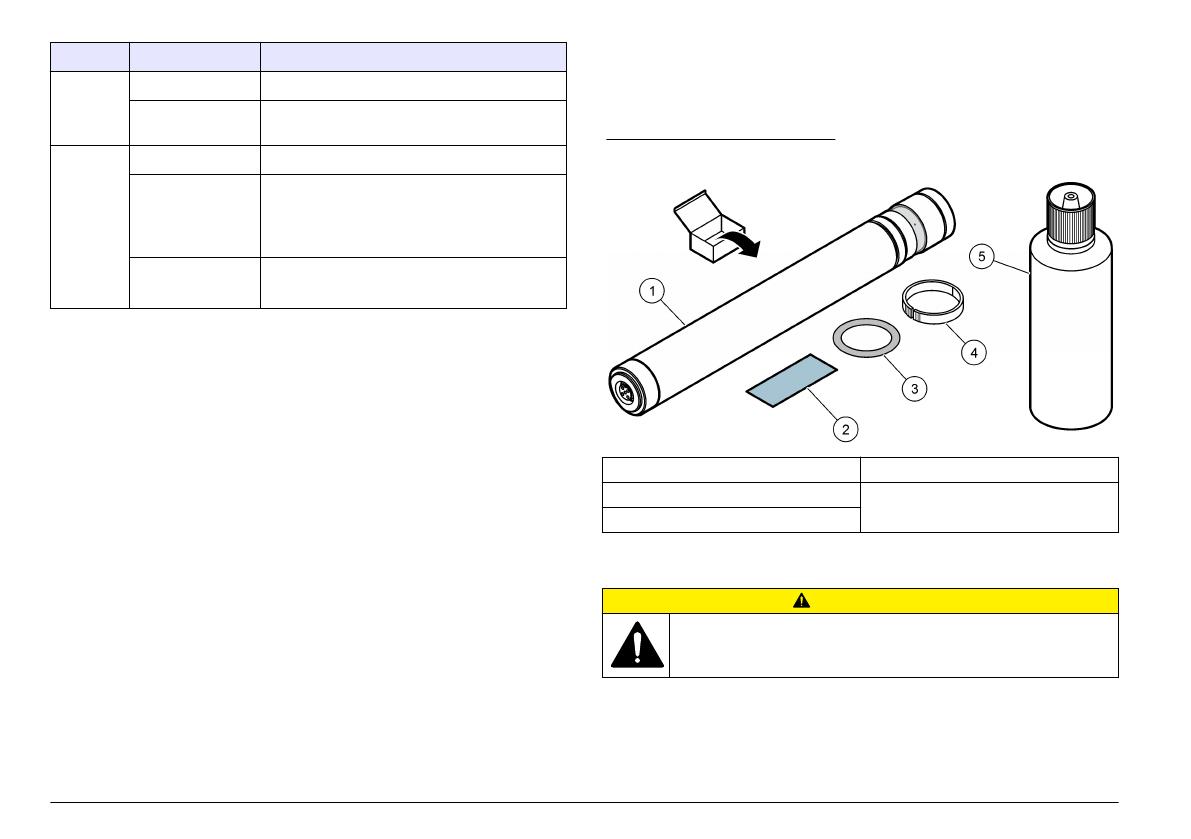
Product components
Refer to Figure 2 to make sure that all components have been received.
If any of these items are missing or damaged, contact the manufacturer
or a sales representative immediately.
Figure 2 Sensor components
1 Chlorine sensor 4 Split ring
2 Special abrasive paper 5 Electrolyte
3 Split ring O-ring
Installation
C A U T I O N
Multiple hazards. Only qualified personnel must conduct the tasks
described in this section of the document.
6 English
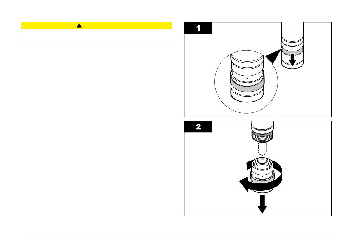
Sensor assembly
C A U T I O N
The electrolyte contains potassium halide and buffer to adjust acidity. Read the
MSDS sheet before opening the electrolyte bottle.
The sensor must be assembled before it can be installed in the chlorine
flow cell. Assembly consists of removing the membrane cap, filling the
membrane cap with electrolyte and putting the membrane cap on to the
electrode shaft.
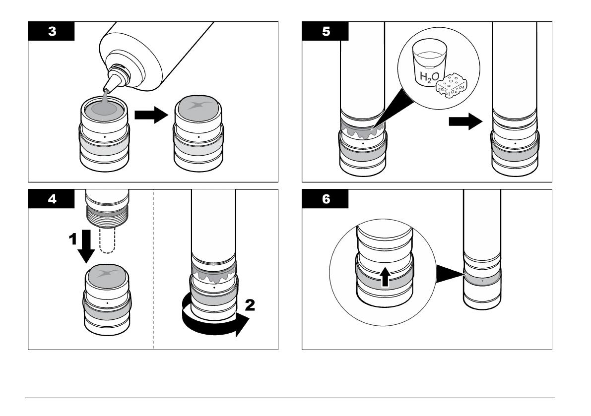
Before assembling the sensor, read these precautions:
• Do not touch the electrodes and keep the electrodes clean. Do not
remove the layer on the electrodes.
• Lift up the rubber band that covers the vent hole marked “M48” on the
membrane cap before removing the membrane cap. The vent allows
air to come into the membrane cap. The membrane will be destroyed
if the vent is covered when the membrane cap is removed, because
vacuum will build up in the membrane cap.
• Do not remove the metallic membrane holder from the cap as this will
damage the membrane.
• Always put the membrane cap on a clean, non-absorbent surface.
• Do not shake the electrolyte bottle as shaking the bottle creates
bubbles. After the electrolyte bottle is opened, store the bottle up side
down.
• Make sure that there are as few bubbles in the electrolyte as possible
when filling the membrane cap with electrolyte. Too many bubbles will
decrease sensor performance.
• Do not close the vent hole marked «M48» in the membrane cap with
your finger when the membrane cap is put on to prevent excess
electrolyte from escaping through the vent. The membrane will be
damaged if the excess electrolyte can not escape. Gently clean off
any electrolyte on the outside of the sensor with a clean, dry cloth or
paper. Make sure not to touch the membrane.
• Make sure the membrane cap is completely put on up to the stop. The
first resistance comes from the O-ring seal, but continue to put on the
cap until the cap hits the electrode shaft.
Assemble the chlorine sensor
English 7
8 English
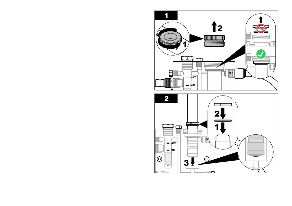
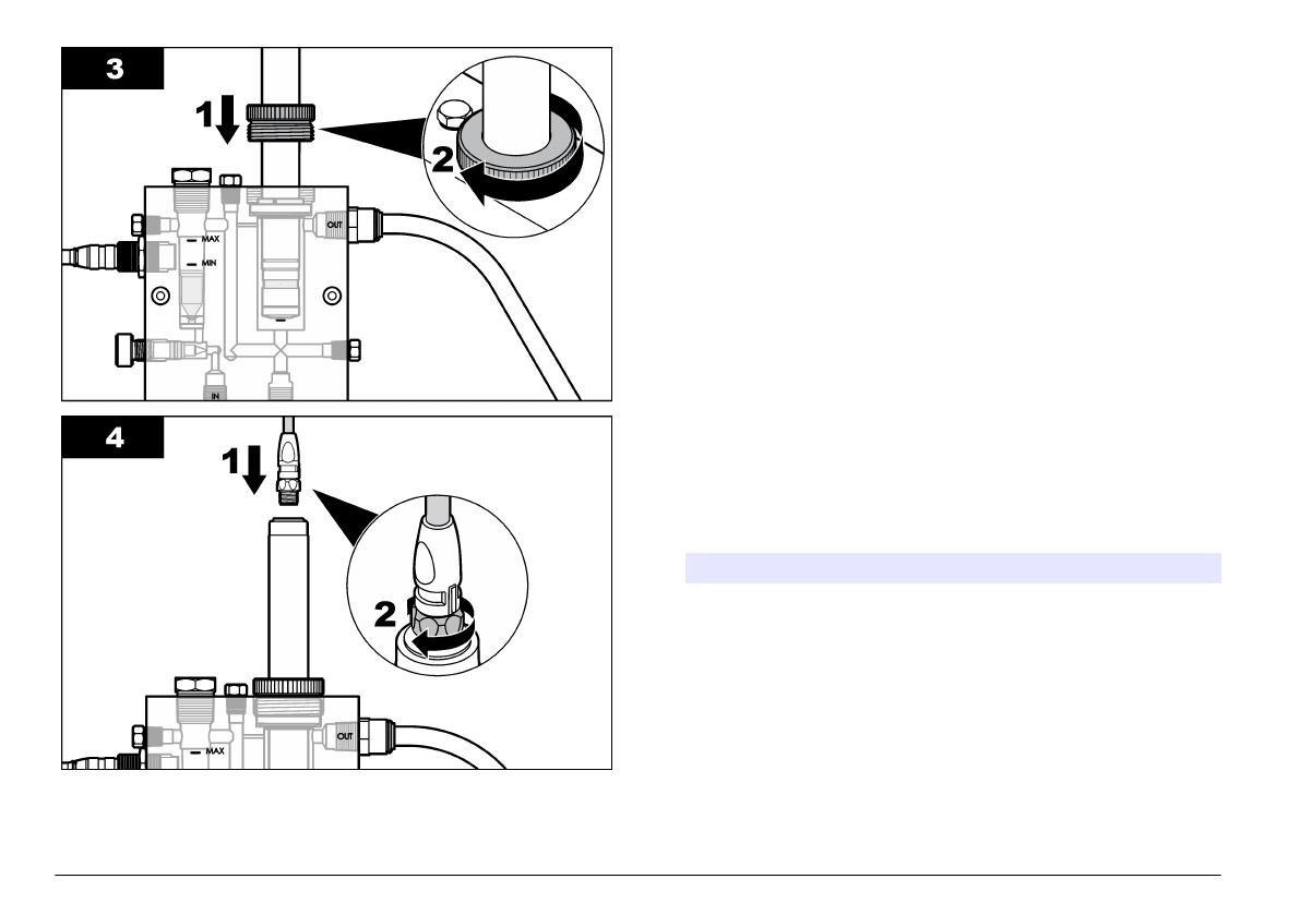
Install the sensor
The sensor must be installed in the flow cell, connected to the gateway,
conditioned and then calibrated before initial use and after maintenance
is done on the sensor. To install and connect the sensor, refer to the
illustrated steps.
To condition the sensor, operate the sensor for 6 to 12 hours until the
sensor readings stabilize. Refer to Diagnostic and test menu
on page 20 for information about viewing sensor readings.
Note: The controller and the sensor connected to it must remain in operation
continuously to maintain calibration.
English 9
Operation
Guidelines for operation
• This sensor is most reliable at residual chlorine concentrations more
than 0.1 ppm (mg/L). A build-up of sediments/contaminates (e.g.,
biological) on the membrane can interfere or prevent later chlorine
measurements.
• This sensor must not be operated in chlorine free water for more than
one day.
• This sensor must not be exposed to pressure impulses and/or
vibrations from the sample water.
User navigation
Refer to the controller documentation for keypad description and
navigation information.
Configure the sensor
Use the Configure menu to enter identification information and display
options for the sensor and to change options for data handling and
storage.
1. Push the MENU key and select Sensor Setup, Configure.
Option Description
EDIT NAME Changes the name that corresponds to the sensor on the
top of the measure screen. The name is limited to
10 characters in any combination of letters, numbers,
spaces or punctuation. The default name is the serial
number of the sensor.
10 English

Option Description
SELECT
PARAM.
Customizes the options for sensor data handling and
storage. Refer to Select the parameters on page 11.
RESET
DEFAULTS
Sets the configuration menu to the default settings. All
sensor information is lost.
Select the parameters
1. Select the type of chlorine sensor used — Total CL2 or Free CL2.
2. Select whether a pH sensor is used — Yes or No.
3. If Yes, select the type of pH sensor used — DIFF PH (pHD) or
COMBO pH (pH combination) and then Chlorine.
4. Customize the sensor parameters:
Option Description
SELECT
UNITS
Sets the units for the sensor measurements-Auto ppb-ppm,
Auto ug/L-mg/L, Fixed ppm or Fixed mg/L.
DISPLAY
FORMAT
Sets the number of decimal places that are shown on the
measure screen-X.XXX, XX.XX (default), XXX.X or XXXX
(Auto).
SELECT
RANGE
Sets the measurement range-0 to 10 ppm.
CAL WATCH Shown if pH sensor is used-refer to Select the Cal Watch
alarm values on page 11.
FILTER Sets a time constant to increase signal stability. The time
constant calculates the average value during a specified
time-0 (filtering disabled) to 60 seconds (average of signal
value for 60 seconds). The filter increases the time for the
sensor signal to respond to changes in the process.
LOG SETUP Sets the time interval for event and data logging for
chlorine concentration and flow status-10, 30 seconds, 1,5,
15 (default), 60 minutes.
Select the Cal Watch alarm values
The Cal Watch menu is used to:
• Set the error and warning alarm conditions for chlorine and/or pH
measurement deviations.
• Set the amount of time a chlorine and/or pH measurement can be
outside the deviation range before an alarm occurs.
• Set the amount of time a chlorine measurement can be 0.5 ppm or
higher before an alarm occurs if the previous chlorine sensor
calibration was done using a process flow with a low chlorine
concentration (LCC) (< 0.5 ppm).
• Set the amount of time a Cal Watch alarm is on before it is canceled
by the instrument if measurements go back in to range.
• Set the percentage rate at which measurements must be outside the
deviation range before an alarm occurs and must be back in range
before an alarm is canceled by the instrument.
To select Cal Watch alarm values:
1. Select Cal Monitor.
2. If the passcode is enabled in the security menu for the controller,
enter the passcode.
3. Select the measurement(s) to monitor (choose one):
Option Description
ALL Enables an error or warning alarm to activate when chlorine
and/or pH measurement deviations occur that are equal to or
higher than the chlorine and pH deviation values selected by
the user.
CL2 ONLY Enables an error or warning alarm to activate when a chlorine
measurement deviation occurs that is equal to or higher than
the chlorine measurement deviation values selected by the
user.
pH ONLY Enables an error or warning alarm to activate when a pH
measurement deviation occurs that is equal to or higher than
the pH measurement deviation values selected by the user.
None Disables all Cal Watch alarms.
English 11

4. Push the ENTER key and select Activate TMR.
5. Set the amount of time a measurement(s) can be outside the
deviation range before an alarm occurs:
Option Description
ALL ACTIVATE TMR: Sets the amount of time the chlorine AND pH
measurements can be out of range before an alarm occurs-10 to
99 minutes (10 minutes default).
CONFID LEVEL: Set the percentage rate at which chlorine AND
pH measurements must be out of range before an alarm occurs
and must be in range before an alarm is automatically canceled
by the instrument-50 to 95% (default).
CL2/pH
ONLY
ACTIVATE TMR: Sets the amount of time the chlorine OR pH
measurements can be out of range before an alarm occurs-10 to
999 minutes (30 minutes default).
CONFID LEVEL: Set the percentage rate at which chlorine OR
pH measurements must be out of range before an alarm occurs
and must be in range before an alarm is automatically canceled
by the instrument-50 to 95% (default).
LCC ACTIVATE TMR: Set the amount of time a chlorine measurement
can be 0.5 ppm or higher before an alarm occurs-10 to
999 minutes (30 minutes default). An alarm only occurs if the
previous chlorine sensor calibration was done using a process
flow with a low chlorine concentration (LCC) (< 0.5 ppm).
CONFID LEVEL: Set the percentage rate at which chlorine
measurements must be 0.5 ppm or higher before an alarm
occurs and must be less than 0.5 ppm before an alarm is
automatically canceled by the instrument-50 to 95% (default).
6. Push the ENTER key and select Deactivate TMR.
7. Set the amount of time an alarm is on before it is automatically
canceled (deactivated) by the instrument if the measurements go
back in to range at the percentage rate (confidence level) selected in
Activate TMR:
Option Description
ALL Sets the amount of time a chlorine AND pH measurement
deviation alarm is on before it is canceled-10 to 99 minutes
(30 minutes default).
Option Description
CL2/pH
ONLY
Sets the amount of time a chlorine OR pH measurement
deviation alarm is on before it is canceled-10 to 999 minutes
(30 minutes default).
LCC Sets the amount of time an LCC alarm is on before it is
canceled-10 to 999 minutes (30 minutes default).
8. Push the ENTER key and select CL2 Deviation.
9. Set the chlorine measurement deviation values that activate alarms:
Option Description
CL2 ERR DEV Set the chlorine measurement deviation that will activate an
error alarm-30 to 99% (50% default).
CL2 WRN DEV Set the chlorine measurement deviation that will activate a
warning alarm-10 to 30% (20% default).
Note: Chlorine deviation is measured by the instrument using the chlorine
value recorded during the last process concentration calibration for chlorine.
10. Push the ENTER key and select pH Deviation.
11. Set the pH measurement deviation values that activate alarms:
Option Description
pH ERR DEV Set the pH measurement deviation that will activate an error
alarm-1 (default) to 3 pH units.
pH WRN DEV Set the pH measurement deviation that will activate a
warning alarm-0.5 (default) to 1 pH unit.
Note: pH deviation is measured by the instrument using the pH value recorded
during the last process concentration calibration for chlorine.
Calibrate the sensor
About sensor calibration
The sensor characteristics slowly shift over time and cause the sensor to
lose accuracy. The sensor must be calibrated regularly to maintain
accuracy. The calibration frequency varies with the application and is
best determined by experience.
12
English

Recalibrate the sensor whenever disconnected from power and removed
from water for more than 15 minutes.
Choosing the calibration method
An initial 2-point calibration, including both zero
3
and slope
(process concentration) measurements, must be done for new or
refurbished sensors.
One or two measurements are required for sensor calibration.
Measurements are made with the chlorine sensor in the flow cell.
When only one measurement is made (1-point calibration), a zero
calibration or a process concentration measurement (grab sample
analysis) is done. A zero calibration can be done chemically by
measuring water with no chlorine or electrically by electronically
removing the calibration offset produced by the gateway
3
. A process
concentration measurement is done chemically by measuring the
chlorine concentration of the process flow with a reference method (grab
sample analysis) and then entering the measured value through the
controller.
When two measurements are made (2-point calibration), the first data
point measured is the zero-point and is determined by doing a zero
calibration either electrically or chemically using the same method as the
1-point calibration
3
. The second data point measured is the process
concentration and is determined by doing a process concentration
measurement (grab sample analysis) using the same method as the 1-
point calibration.
Note: When a chemical zero calibration is done, the instrument automatically does
an electrical zero calibration before the chemical zero calibration and shows both
offsets in the calibration results.
1-point calibration procedure
1. Push the MENU key and select Sensor Setup, Calibrate, Chlorine.
2. Select 1 Point Sample.
3. If the passcode is enabled in the security menu for the controller,
enter the passcode.
4. Select either Zero Cal (zero calibration) or Process Conc (process
concentration calibration).
5. Select the option for the output signal during calibration:
Option Description
ACTIVE The instrument sends the current measured output value
during the calibration procedure.
HOLD The sensor output value is held at the current measured value
during the calibration procedure.
TRANSFER A preset output value is sent during calibration. Refer to the
controller user manual to change the preset value.
6. If Process Conc was selected:
a. Push ENTER.
The measured value is shown.
b. Wait for the value to stabilize and push ENTER
4
to enter a
process flow measurement.
c. Measure the chlorine concentration of the process flow (grab
sample analysis) with an instrument using a reference method
(e.g., DPD). Use the arrow keys to enter the measured value and
push ENTER.
7. If Zero Cal was selected, select the type of calibration:
Option Description
ELECTRICAL The offset produced by the gateway is removed to set the
zero-point (no sample used).
CHEMICAL Water with no chlorine is measured to set the zero-point.
8. If Electrical was selected, wait for the value to stabilize and push
ENTER
4
to set the zero-point electrically.
3
An electrical zero calibration is recommended. A chemical zero calibration is only recommended if the process flow chlorine concentrations is
routinely lower than 0.5 ppm.
4
If the option for Auto Stab (auto stabilization) is set to Yes in the Calibration Options menu, the screen will advance to the next step automatically.
Refer to Change the calibration options on page 15.
English 13

9. If Chemical was selected:
a. Turn off the process flow and put water with no chlorine through
the flow cell. Make sure the temperature of the water with no
chlorine is as close as possible to the process sample flow
temperature.
b. Push ENTER.
The measured value is shown.
c. Wait for the value to stabilize and push ENTER
4
to set the zero-
point chemically.
10. Review the calibration result:
• Passed—the sensor is calibrated and ready to measure samples.
The slope and/or offset values are shown.
• Failed—the calibration slope or offset is outside of accepted limits.
Do sensor maintenance (refer to Maintenance on page 16) and
then repeat the calibration.
11. If the calibration passed, push ENTER to continue.
12. If the option for operator ID is set to Yes in the Calibration Options
menu, enter an operator ID. Refer to Change the calibration options
on page 15.
13. On the New Sensor screen, select whether the sensor is new:
Option Description
YES The sensor was not calibrated previously with this instrument. The
days of operation and previous calibration curves for the sensor are
reset.
NO The sensor was calibrated previously with this instrument.
14. Return the sensor to the process and push ENTER.
The output signal returns to the active state and the measured
sample value is shown on the measure screen.
Note: If the output mode is set to hold or transfer, select the delay time when
the outputs return to the active state.
2-point calibration procedure
1. Push the MENU key and select Sensor Setup, Calibrate, Chlorine.
2. Select 2 Point Sample.
3. If the passcode is enabled in the security menu for the controller,
enter the passcode.
4. Select the option for the output signal during calibration:
Option Description
ACTIVE The instrument sends the current measured output value
during the calibration procedure.
HOLD The sensor output value is held at the current measured value
during the calibration procedure.
TRANSFER A preset output value is sent during calibration. Refer to the
controller user manual to change the preset value.
5. Select the type of calibration:
Option Description
ELECTRICAL The offset produced by the gateway is removed to set the
zero-point (no sample used). Then a process sample is
measured to set the second point from which the slope is
calculated.
CHEMICAL Water with no chlorine is measured to set the zero-point.
Then a process sample is measured to set the second point
from which the slope is calculated.
6. If Electrical was selected:
a. Wait for the value to stabilize and push ENTER
5
to set the zero-
point electrically.
b. Push ENTER to continue the calibration.
The measured value of the process concentration is shown.
c. Wait for the value to stabilize and push ENTER
5
to enter a
process flow measurement.
5
If the option for Auto Stab (auto stabilization) is set to Yes in the Calibration Options menu, the screen will advance to the next step automatically.
Refer to Change the calibration options on page 15.
14 English

7. If Chemical was selected:
a. Turn off the process flow and put water with no chlorine through
the flow cell. Make sure the temperature of the water with no
chlorine is as close as possible to the process sample flow
temperature.
b. Push ENTER.
The measured value is shown.
c. Wait for the value to stabilize and push ENTER
5
to set the zero-
point chemically.
d. Turn off the flow of water with no chlorine and turn on the process
flow.
e. Push ENTER.
The measured value is shown.
f. Wait for the value to stabilize and push ENTER
5
to enter a
process flow measurement.
8. Measure the chlorine concentration of the process flow (grab sample
analysis) with an instrument using a reference method (e.g., DPD).
Use the arrow keys to enter the measured value and push ENTER.
9. Review the calibration result:
• Passed—the sensor is calibrated and ready to measure samples.
The slope and/or offset values are shown.
• Failed—the calibration slope or offset is outside of accepted limits.
Do sensor maintenance (refer to Maintenance on page 16) and
then repeat the calibration.
10. If the calibration passed, push ENTER to continue.
11. If the option for operator ID is set to Yes in the Calibration Options
menu, enter an operator ID. Refer to Change the calibration options
on page 15.
12. On the New Sensor screen, select whether the sensor is new:
Option Description
YES The sensor was not calibrated previously with this instrument. The
days of operation and previous calibration curves for the sensor are
reset.
NO The sensor was calibrated previously with this instrument.
13. Return the sensor to the process and push ENTER.
The output signal returns to the active state and the measured
sample value is shown on the measure screen.
Note: If the output mode is set to hold or transfer, select the delay time when
the outputs return to the active state.
Reset calibration to defaults
To remove a bad calibration, replace the user calibration settings with
the default calibration settings using the Calibrate menu. Then
recalibrate the sensor when needed.
1. Push the MENU key and select Sensor Setup, Calibrate, [Select
Sensor], Reset Defaults.
2. If the passcode is enabled in the security menu for the controller,
enter the passcode.
3. Select Yes and push Enter.
Change the calibration options
The user can set a calibration reminder, enable auto stabilization during
calibrations or include an operator ID with calibration data from the Cal
Options menu.
1. Push the MENU key and select Sensor Setup, Calibrate, [Select
Sensor], Cal Options.
2. Customize the options:
Option Description
AUTO STAB Enables the system to accept measurement signal values
during calibrations and advance to the next step of the
calibration when the system determines the measurement
signal has stabilized-On or Off (default). Enter a
stabilization range-25 to 75 ppb (0.025 to 0.075 ppm).
CAL REMINDER Sets a reminder for the next calibration in days, months or
years.
OP ID ON CAL Includes an operator ID with calibration data—Yes or No
(default). The ID is entered during the calibration.
English 15
Data log
The controller provides one data log for each sensor. The data log stores
the measurement data at selected intervals (user configurable). The data
log can be read out in a CSV format. For instructions on downloading the
logs, please refer to the controller user manual.
Refer to Select the parameters on page 11 for information about setting
time intervals for data storage in the data log.
Modbus registers
A list of Modbus registers is available for network communication. Refer
to the manufacturer’s website for more information.
Maintenance
W A R N I N G
Multiple hazards. Do not disassemble the instrument for maintenance.
If the internal components must be cleaned or repaired, contact the
manufacturer.
C A U T I O N
Multiple hazards. Only qualified personnel must conduct the tasks
described in this section of the document.
Maintenance schedule
Maintenance task Frequency
Polish the electrode When sensor readings are unstable or
the slope is too low
Replace the membrane cap
6
1 year
(The cap may need to be replaced
more often depending on water
quality.)
Maintenance task Frequency
Replace the electrolyte 3 to 6 months
Replace the sensor 3 years
(The sensor may need to be replaced
more often depending on water quality
and application.)
Remove the sensor from the flow cell
Note: The sensor can be removed from water for up to 1 hour to do maintenance
on the sensor. The membrane cap and electrolyte will need to be replaced after
1 hour.
6
The electrolyte is replaced when the membrane cap is replaced.
16 English

English 17
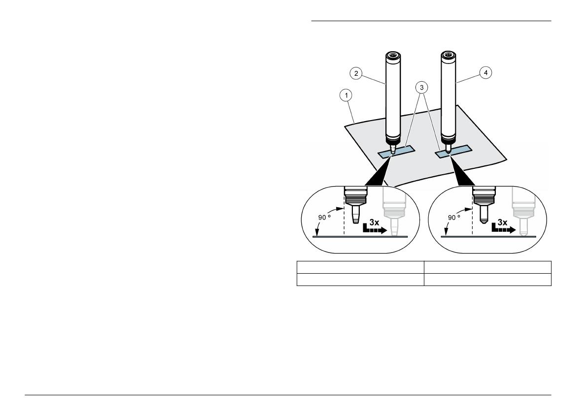
Polish the electrode tip
Polish the flat tip of the electrode with the special abrasive paper
provided.
Note: If calibration is impossible due to unstable sensor readings or too low
calibration slope, replace the electrolyte and membrane cap. Only polish the
electrode tip if replacing the electrolyte and membrane cap do not correct the
problem.
1. Disconnect the cable from the sensor.
2. Remove the sensor from the flow cell.
3. Read the precautions in Sensor assembly on page 7.
4. Lift up the rubber band that covers the vent hole marked “M48” on
the membrane cap and slide the rubber band over so it does not
cover the vent hole.
5. Turn the membrane cap counter-clockwise and remove the
membrane cap from the sensor.
6. Clean the electrode with a clean, dry paper towel.
7. Polish the dry electrode tip (Figure 3). Hold one corner of the special
abrasive paper while doing procedure.
Note: No additional force should be applied downward other than the sensor
weight.
8. Assemble the sensor with the old membrane cap.
9. Install the sensor in the flow cell and connect the sensor cable.
10. Condition the sensor by operating it for 6 to 12 hours. The sensor is
conditioned when the sensor readings stabilize. Refer to Diagnostic
and test menu on page 20 for information about viewing sensor
readings.
11. Calibrate the sensor.
Figure 3 Polish the electrode with the special abrasive
paper
1 Dry, clean paper towel 3 Special abrasive paper
2 Free chlorine sensor 4 Total chlorine sensor
Replace the membrane cap
1. Disconnect the cable from the sensor.
2. Remove the sensor from the flow cell.
3. Read the precautions in Sensor assembly on page 7.
4. Turn the membrane cap counter-clockwise and remove the
membrane cap from the sensor.
5. Dispose of the old membrane cap.
18
English
6. Assemble the sensor with a new membrane cap.
7. Install the sensor in the flow cell and connect the sensor cable.
8. Condition the sensor by operating it for 6 to 12 hours. The sensor is
conditioned when the sensor readings stabilize. Refer to Diagnostic
and test menu on page 20 for information about viewing sensor
readings.
9. Calibrate the sensor.
Replace the electrolyte
1. Disconnect the cable from the sensor.
2. Remove the sensor from the flow cell.
3. Read the precautions in Sensor assembly on page 7.
4. Lift up the rubber band that covers the vent hole marked “M48” on
the membrane cap and slide the rubber band over so it does not
cover the vent hole.
5. Turn the membrane cap counter-clockwise and remove the
membrane cap from the sensor.
6. Hold the membrane cap with the electrolyte on the bottom and shake
up and down 1-2 times to remove old electrolyte.
7. Assemble the sensor with the membrane cap.
8. Install the sensor in the flow cell and connect the sensor cable.
9. Condition the sensor by operating it until the sensor readings
stabilize. Refer to Diagnostic and test menu on page 20 for
information about viewing sensor readings.
10. Calibrate the sensor.
Prepare the sensor for storage
C A U T I O N
The electrolyte contains potassium halide and buffer to adjust acidity. Read the
MSDS sheet before opening the electrolyte bottle.
The sensor can be stored for up to 3 years from the date of manufacture
when prepared as described. Refer to Specifications on page 3 for
storage specifications.
Note: Do not touch the electrodes and keep the electrodes clean. Do not remove
the layer on the electrodes.
1. Turn the membrane cap counter-clockwise and remove the
membrane cap from the sensor.
2. Rinse the membrane cap and electrode in clean water.
3. Dry the membrane cap and electrode with a clean, dry paper towel in
a place free of dust.
4. Loosely put the membrane cap on to the electrode shaft to protect
the electrode. The membrane must not rest against the measuring
electrode.
Remove the sensor from storage
Pre-requisite: Obtain a new membrane cap. The old membrane cap
cannot be used again.
1. Read the precautions in Sensor assembly on page 7.
2. Turn the membrane cap counter-clockwise and remove the
membrane cap from the sensor.
3. Dispose of the old membrane cap.
4. Polish the electrode tip with the special abrasive paper.
5. Assemble the sensor with a new membrane cap.
6. Install the sensor in the flow cell and connect the sensor cable.
7. Condition the sensor by operating it for 6 to 12 hours. The sensor is
conditioned when the sensor readings stabilize. Refer to Diagnostic
and test menu on page 20 for information about viewing sensor
readings.
8. Calibrate the sensor.
English
19
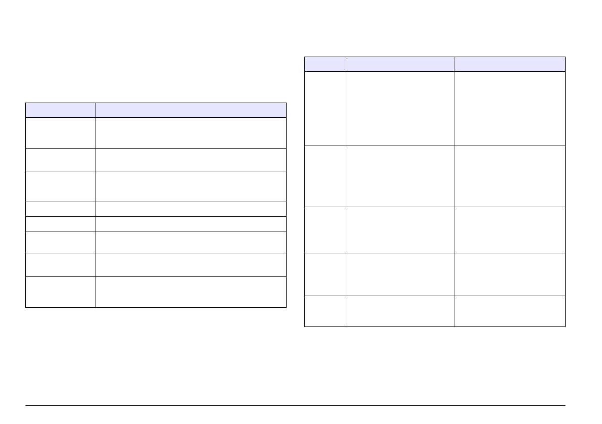
Troubleshooting
Diagnostic and test menu
The diagnostic and test menu shows current and historical information
about the chlorine analyzer. Refer to Table 1. To access the diagnostic
and test menu, push the MENU key and select Sensor Setup, Diag/Test.
Table 1 DIAG/TEST menu
Option Description
GATEWAY INFO Shows the firmware version, driver version, serial number
and boot version for the controller and the types of
sensors connected to the controller.
CAL DAYS Shows the number of days since the sensor was last
calibrated.
CAL HISTORY Shows a list of the times when the sensor was calibrated.
Push ENTER to scroll through the entries and view a
summary of the calibration data.
RST CAL HISTORY Resets the sensor calibration history. Requires passcode.
SIGNALS Shows the sensor measurement signal value in mV.
SENSOR DAYS Shows the number of days the sensor has been in
operation.
RST SENSORS Resets the sensor days and calibration days to default.
Requires passcode.
CALIBRATION Shows the slope and offset values for chlorine and pH (if
pH sensor is used). Shows the offset value for the
temperature (if pH sensor is used).
Error list
Errors may occur for various reasons. The sensor reading on the
measurement screen flashes. All outputs are held when specified in the
controller menu. To show the sensor errors, push the MENU key and
select Sensor Diag, Error List. A list of possible errors is shown below.
Table 2 Error list for the sensor
Error Description Resolution
CL CAL
REQD
A chlorine calibration and/or pH
calibration is required.
The chlorine and/or pH
measurement has changed
enough to cause a Cal Watch
alarm to occur. Refer to the
chlorine sensor manual for
more information.
Calibrate the chlorine sensor
and/or pH sensor.
CL MAINT
REQD
Chlorine sensor maintenance is
required.
The slope is less than 30% or
more than 300% of the default.
The default slope is
100 mV/ppm (100%).
Do sensor maintenance and then
repeat the calibration, or replace
the sensor. Refer to the chlorine
sensor manual for more
information.
CL MAINT
REQD
Chlorine sensor maintenance is
required.
The offset is too high (more
than ±50 mV).
Do sensor maintenance and then
repeat the calibration, or replace
the sensor. Refer to the chlorine
sensor manual for more
information.
CONC
TOO LOW
The chlorine signal is > 0 mV.
The potential delivered by the
sensor is outside of the range
0 to -2500 mV.
A connection error occurred or
the chlorine sensor is not
polarized/equilibrated in the
sample sufficiently.
CONC
TOO HIGH
The chlorine signal is less than
-2500 mV or greater than
2500 mV (by absolute value).
Warning list
A warning does not affect the operation of menus, relays and outputs. A
warning icon flashes and a message is shown on the bottom of the
measurement screen. To show the sensor warnings, push the MENU
20
English

I56-2081-115
© System Sensor 2013
1
DB200-01-01
ИНСТРУКЦИЯ
ПО
УСТАНОВКЕ
И
ОБСЛУЖИВАНИЮ
ПОЖАРНЫХ
ДЫМОВЫХ
ЛИНЕЙНЫХ
ОПТИКОЭЛЕКТРОННЫХ
ОДНОКОМПОНЕНТНЫХ
ИЗВЕЩАТЕЛЕЙ
ИП
212-125(6500R)
и
ИП
212-126 (6500RS)
ОБЩИЕ
СВЕДЕНИЯ
Дымовые
оптико
—
электронные
линейные
однокомпонентные
извещатели
6500R
и
6500RS
предназначены
для
защиты
помещений
больших
площадей
.
Они
состоят
из
приемо
—
передатчика
,
выполненного
в
виде
одного
блока
,
и
пассивного
рефлектора
.
Появление
дыма
в
пространстве
между
компонентами
вызывает
снижение
уровня
сигнала
,
возвращающегося
к
приемнику
.
Когда
затухание
достигнет
порога
,
установленного
в
приемо
—
передатчике
,
извещатель
сформирует
сигнал
ПОЖАР
.
Блокировка
луча
вызывает
формирование
сигнала
НЕИСПРАВНОСТЬ
.
Медленное
снижение
уровня
сигнала
из
—
за
постепенного
накопления
пыли
или
грязи
на
компонентах
извещателя
компенсируется
микроконтроллером
,
который
постоянно
отслеживает
уровень
сигнала
и
периодически
корректирует
значения
порогов
ПОЖАР
и
НЕИСПРАВНОСТЬ
.
Когда
будет
достигнута
граница
диапазона
автокомпенсации
,
извещатель
сформирует
сигнал
НЕИСПРАВНОСТЬ
,
который
говорит
о
необходимости
проведения
технического
обслуживания
.
Модель
6500RS
дополнительно
содержит
калиброванный
тестовый
фильтр
,
управляемый
серводвигателем
,
который
позволяет
дистанционно
произвести
контроль
работоспособности
извещателя
в
полном
объеме
.
ТЕХНИЧЕСКИЕ
ХАРАКТЕРИСТИКИ
:
Характеристики
назначения
Дальность
от
5
до
70
метров
от
70
до
100
метров
,
при
использовании
BEAMLRK
Чувствительность
:
Уровень
1:
25%
затухания
Уровень
2:
30%
затухания
Уровень
3:
40%
затухания
Уровень
4:
50%
затухания
Адаптивная
А
1
Уровень
5:
от
30%
до
50%
Адаптивная
А
2
Уровень
6:
от
40%
до
50%
Допустимое
отклонение
:
детектор
:
± 0,5
°
рефлектор
:
± 10
°
Время
выдачи
сигнала
:
ПОЖАР
20
с
типовое
НЕИСПРАВНОСТЬ
30
с
типовое
Время
подтверждения
сигнала
ПОЖАР
(
после
сброса
по
питанию
)
не
более
5
с
Время
сброса
(
по
питанию
)
не
более
0,3
с
Время
перехода
в
дежурный
режим
не
более
60
с
Требования
к
окружающей
среде
Температурный
диапазон
от
— 30
°
С
до
+ 55
°
С
Влажность
от
10%
до
93% (
без
конденсата
)
Степень
защиты
оболочкой
IP54
Механические
характеристики
Вес
в
упаковке
1,77
кг
Габариты
(
Без
передней
панели
) 229
х
178
х
84
мм
Габариты
(
С
передней
панелью
) 253
х
193
х
84
мм
Сечение
проводников
от
0,33
мм
2
до
3,1
мм
2
Диапазон
юстировки
детектора
±10
°
по
горизонтали
и
вертикали
Электрические
характеристики
Напряжение
питания
:
6500R
от
10,2
до
32
В
6500RS
от
15
до
32
В
Ток
в
дежурном
режиме
17
мА
при
24
В
Ток
в
режиме
ПОЖАР
38,5
мА
при
24
В
Ток
в
режиме
НЕИСПРАВНОСТЬ
8,5
мА
при
24
В
Ток
6500RS
в
режиме
ТЕСТ
500
мА
,
пиковый
Релейные
контакты
0,5
А
при
=30
В
Выход
выносного
индикатора
Напряжение
:
от
15
до
32
В
Ток
:
от
6
до
15
мА
,
ограничен
резистором
2,2
кОм
Извещатели
6500R
и
6500RS
соответствуют
требованиям
ГОСТ
Р
53325-2009
и
Свода
Правил
СП
5.13130.2009.
КОМПЛЕКТ
ПОСТАВКИ
Наименование
Количество
Блок
приемо
—
передатчика
1
Декоративная
крышка
для
покраски
1
Рефлектор
(6500REFL)
1
Съемные
колодки
терминалов
5
Инструкция
1
Оранжевый
стикер
для
рефлектора
1
Токоограничивающий
резистор
1000
Ом
1
Перемычка
(
резистор
0
Ом
)
1
АКСЕССУАРЫ
6500LRK
Набор
для
увеличения
дальности
защищаемой
зоны
от
70
м
до
100
м
содержит
три
дополнительных
рефлектора
,
которые
устанавливаются
вместе
с
основным
рефлектором
в
виде
квадрата
.
6500SMK
Монтажный
комплект
для
приемо
—
передатчика
.
Создает
дополнительную
глубину
43
мм
и
тем
самым
дает
возможность
ввода
кабеля
через
боковую
стенку
.
6500MMK
Универсальный
кронштейн
позволяет
установить
извещатели
6500, 6500RS (
используются
с
6500-SMK)
и
рефлектор
на
потолке
или
на
стенах
,
где
угол
установки
относительно
друг
друга
превышает
10°.
BEAMHK
Нагревательный
элемент
повышает
температуру
на
поверхности
светофильтра
и
оптической
системы
извещателя
относительно
окружающей
среды
и
защищает
от
образования
конденсата
и
инея
.
BEAMHKR
Нагревательный
элемент
повышает
температуру
на
поверхности
рефлектора
относительно
окружающей
среды
и
защищает
от
образования
конденсата
и
инея
.
6500RTS-KEY, RTS151KEY, RTS451 KEY, RTS151, RTS451
Выносные
пульты
позволяют
дистанционно
протестировать
извещатель
,
активизировать
его
и
перевести
в
дежурный
режим
.
При
тестировании
с
помощью
6500RTS-KEY
автоматически
отслеживается
уровень
запыления
извещателя
.
Режим
ПОЖАР
в
6500RTS-KEY,
RTS151KEY, RTS451KEY, RTS151, RTS451
индицируется
включением
красного
светодиода
.
Режим
НЕИСПРАВНОСТЬ
в
6500RTS-KEY
индицируется
включением
светодиода
желтого
цвета
.
RA400Z, RA100Z
Выносной
оптический
сигнализатор
предназначен
для
индикации
режима
НЕИСПРАВНОСТЬ
при
использовании
выносных
пультов
RTS151KEY,
RTS451KEY, RTS151, RTS451
или
ПОЖАР
без
применения
пультов
.
УСТАНОВКА
ИЗВЕЩАТЕЛЯ
Размещение
Размещение
извещателей
6500
должно
производиться
в
соответствии
с
требованиями
действующей
нормативной
базы
.
Места
для
установки
Линейные
дымовые
извещатели
требуют
установки
на
жесткие
неподвижные
конструкции
.
НЕ
УСТАНАВЛИВАЙТЕ
приемо
—
передатчик
на
постоянно
движущиеся
,
вибрирующие
или
деформирующиеся
поверхности
,
которые
могут
вызвать
ложные
сигналы
ПОЖАР
или
НЕИСПРАВНОСТЬ
.
Рефлектор
имеет
намного
больший
допуск
перемещения
,
чем
приемо
—
передатчик
.
В
случае
,
когда
для
установки
имеется
только
одна
прочная
поверхность
,
на
нее
должен
устанавливаться
приемо
—
передатчик
.
В
технических
характеристиках
указаны
максимально
допустимые
изменения
положения
приемо
—
передатчика
и
рефлектора
.
Превышение
предельных
значений
может
быть
причиной
возникновения
недостоверных
сигналов
ПОЖАР
и
НЕИСПРАВНОСТЬ
.