 Contents:
1. General;
2. Configuration;
3. Specifications;
4. Consumable Parts;
5. External Views and Internal Structures;
6. Adjustments;
7. Simulations;
8. User Programs (The user programs allow the parameters of certain functions to be set, changed, or canceled as desired);
8.1 List of user programs;
8.2 Setting the user programs;
8.3 Toner cartridge life;
9. Trouble Code List for Sharp AR-5516 / AR-5520.;
10. Maintenance;
11. Disassembly and Assembly;
12. Flash ROM Version up Procedure;
13. Electrical Section.
Download Sharp AR-5516 / AR-5520. Service Manual
Все материалы на сайте представлены исключительно для ознакомления. Все торговые марки и права на публикуемые материалы принадлежат их владельцам.
All materials on the site are presented solely for information. All trademarks and copyrights in the published materials belong to their respective owners.
 Loading…
![]()
AR-5516 AR-5516S
AR-5516D
AR-5520 AR-5520S
AR-5520D
(With RSPF installed)
CODE : 00ZAR5520/S1E
DIGITAL COPIER
AR-5520 AR-5516
AR-5520S AR-5516S MODEL AR-5520D AR-5516D
|
CONTENTS |
|||||
|
[ 1 ] GENERAL . . . . . . . . . . . . . . . . . . . . . . . . . . . . . . . . . . . . . . . . |
. 1 |
— 1 |
|||
|
[ 2 ] CONFIGURATION. . . . . . . . . . . . . . . . . . . . . . . . . . . . . . . . . . . |
2 |
— 1 |
|||
|
[ 3 ] SPECIFICATIONS. . . . . . . . . . . . . . . . . . . . . . . . . . . . . . . . . . . |
3 |
— 1 |
|||
|
[ 4 ] CONSUMABLE PARTS. . . . . . . . . . . . . . . . . . . . . . . . . . . . . . . |
4 |
— 1 |
|||
|
[ 5 ] EXTERNAL VIEWS AND INTERNAL STRUCTURES . . . . . . . |
5 |
— 1 |
|||
|
[ 6 |
] ADJUSTMENTS . . . . . . . . . . . . . . . . . . . . . . . . . . . . . . . . . . . . |
6 |
— 1 |
||
|
[ 7 |
] SIMULATIONS . . . . . . . . . . . . . . . . . . . . . . . . . . . . . . . . . . . . . |
7 |
— 1 |
||
|
[ 8 |
] USER PROGRAMS . . . . . . . . . . . . . . . . . . . . . . . . . . . . . . . . . |
8 |
— 1 |
||
|
[ 9 |
] TROUBLE CODE LIST . . . . . . . . . . . . . . . . . . . . . . . . . . . . . . . |
9 |
— 1 |
||
|
[10] MAINTENANCE . . . . . . . . . . . . . . . . . . . . . . . . . . . . . . . . . . . |
10 |
— 1 |
|||
|
[11] DISASSEMBLY AND ASSEMBLY . . . . . . . . . . . . . . . . . . . . . . |
11 |
— 1 |
|||
|
[12] FLASH ROM VERSION UP PROCEDURE . . . . . . . . . . . . . . |
12 |
— 1 |
|||
|
[13] ELECTRICAL SECTION . . . . . . . . . . . . . . . . . . . . . . . . . . . . . |
13 |
— 1 |
Parts marked with “ “ are important for maintaining the safety of the set.
Be sure to replace these parts with specified ones for maintaining the safety and performance of the set.
This document has been published to be used for SHARP CORPORATION after sales service only.
The contents are subject to change without notice.
CONTENTS
[1] GENERAL
1.Note for servicing . . . . . . . . . . . . . . . . . . . . . . . . . . . . . . . 1-1
[2] CONFIGURATION
1.System Configurations . . . . . . . . . . . . . . . . . . . . . . . . . . . 2-1
[3] SPECIFICATIONS
1.Copy mode . . . . . . . . . . . . . . . . . . . . . . . . . . . . . . . . . . . . 3-1
[4] CONSUMABLE PARTS
1.Supply system table . . . . . . . . . . . . . . . . . . . . . . . . . . . . . 4-1 2.Environmental conditions . . . . . . . . . . . . . . . . . . . . . . . . . 4-3 3. Production number identification . . . . . . . . . . . . . . . . . . . 4-3
[5] EXTERNAL VIEWS AND INTERNAL STRUCTURES
1.Appearance. . . . . . . . . . . . . . . . . . . . . . . . . . . . . . . . . . . . 5-1 2.Internal . . . . . . . . . . . . . . . . . . . . . . . . . . . . . . . . . . . . . . . 5-1 3.Operation Section . . . . . . . . . . . . . . . . . . . . . . . . . . . . . . 5-2 4.Motor, solenoid, clutch . . . . . . . . . . . . . . . . . . . . . . . . . . . 5-3 5.Sensor, switch. . . . . . . . . . . . . . . . . . . . . . . . . . . . . . . . . . 5-4 6.PWB unit . . . . . . . . . . . . . . . . . . . . . . . . . . . . . . . . . . . . . . 5-5 7.Cross sectional view . . . . . . . . . . . . . . . . . . . . . . . . . . . . . 5-6
[6] ADJUSTMENTS
1.Adjustment item list . . . . . . . . . . . . . . . . . . . . . . . . . . . . . . 6-1 2.Copier adjustment . . . . . . . . . . . . . . . . . . . . . . . . . . . . . . . 6-1
[7] SIMULATIONS
1.Entering the simulation mode . . . . . . . . . . . . . . . . . . . . . . 7-1 2.Canceling the simulation mode . . . . . . . . . . . . . . . . . . . . . 7-1 3.List of simulations . . . . . . . . . . . . . . . . . . . . . . . . . . . . . . . 7-1 4.Contents of simulations. . . . . . . . . . . . . . . . . . . . . . . . . . . 7-3
[8] USER PROGRAMS
1.List of user programs . . . . . . . . . . . . . . . . . . . . . . . . . . . . 8-1 2.Setting the user programs . . . . . . . . . . . . . . . . . . . . . . . . 8-4 3.Toner cartridge life . . . . . . . . . . . . . . . . . . . . . . . . . . . . . . 8-4
[9] TROUBLE CODE LIST
1.Trouble code list . . . . . . . . . . . . . . . . . . . . . . . . . . . . . . . . 9-1 2.Details of trouble codes . . . . . . . . . . . . . . . . . . . . . . . . . . 9-1
[10] MAINTENANCE
1.Maintenance table . . . . . . . . . . . . . . . . . . . . . . . . . . . . . . 10-1 2.Maintenance display system . . . . . . . . . . . . . . . . . . . . . . 10-2 3.Note for replacement of consumable parts . . . . . . . . . . . 10-2
[11] DISASSEMBLY AND ASSEMBLY
1.High voltage section/Duplex transport section. . . . . . . . . 11-1 2.Optical section . . . . . . . . . . . . . . . . . . . . . . . . . . . . . . . . . 11-2 3.Fusing section . . . . . . . . . . . . . . . . . . . . . . . . . . . . . . . . . 11-4 4.Paper exit section . . . . . . . . . . . . . . . . . . . . . . . . . . . . . 11-6 5.MCU. . . . . . . . . . . . . . . . . . . . . . . . . . . . . . . . . . . . . . . . . 11-8 6.Optical frame unit. . . . . . . . . . . . . . . . . . . . . . . . . . . . . . . 11-8 7.LSU . . . . . . . . . . . . . . . . . . . . . . . . . . . . . . . . . . . . . . . . . 11-9 8.Tray paper feed section/Paper transport section . . . . . . 11-9 9.Bypass tray section . . . . . . . . . . . . . . . . . . . . . . . . . . . . 11-11 10.Power section . . . . . . . . . . . . . . . . . . . . . . . . . . . . . . . 11-13 11.Developing section . . . . . . . . . . . . . . . . . . . . . . . . . . . 11-14 12.Process section . . . . . . . . . . . . . . . . . . . . . . . . . . . . . . 11-15 13.Others . . . . . . . . . . . . . . . . . . . . . . . . . . . . . . . . . . . . . 11-15
[12] FLASH ROM VERSION UP PROCEDURE
1.Preparation . . . . . . . . . . . . . . . . . . . . . . . . . . . . . . . . . . . 12-1 2.Download procedure . . . . . . . . . . . . . . . . . . . . . . . . . . . . 12-1 3.Installation procedure . . . . . . . . . . . . . . . . . . . . . . . . . . . 12-2
[13] ELECTRICAL SECTION
1.Block diagram . . . . . . . . . . . . . . . . . . . . . . . . . . . . . . . . . 13-1 2.Actual wiring diagram . . . . . . . . . . . . . . . . . . . . . . . . . . . 13-2
[1] GENERAL
1. Note for servicing
|
Pictogram |
|
|
The label ( |
) in the fusing area of the machine indicates the |
following:
 : Caution, risk of danger
  : Caution, hot surface
A. Warning for servicing
•The fusing area is hot. Exercise care in this area when removing misfed paper.
•Do not look directly at the light source. Doing so may damage your eyes.
B. Cautions for servicing
•Do not switch the machine rapidly on and off. After turning the machine off, wait 10 to 15 seconds before turning it back on.
•Machine power must be turned off before installing any supplies. •Place the machine on a firm, level surface.
•Do not install the machine in a humid or dusty location.
•When the machine is not used for a long time, for example, during prolonged holidays, turn the power switch off and remove the power cord from the outlet.
•When moving the machine, be sure to turn the power switch off and remove the power cord from the outlet.
•Do not cover the machine with a dust cover, cloth or plastic film while the power is on. Doing so may prevent heat dissipation, damaging the machine.
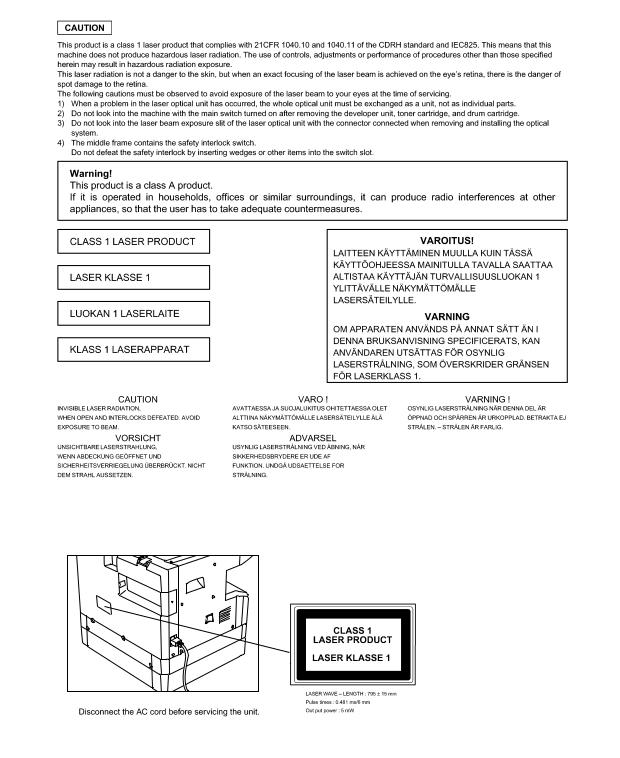
•Use of controls or adjustments or performance of procedures other than those specified herein may result in hazardous laser radiation exposure.
•The socket-outlet shall be installed near the machine and shall be easily accessible.
C. Note for installation place
Improper installation may damage the machine. Please note the following during initial installation and whenever the machine is moved.
Caution : If the machine is moved from a cool place to a warm place, condensation may form inside the machine. Operation in this condition will cause poor copy quality and malfunctions. Leave the machine at room temperature for at least 2 hours before use.
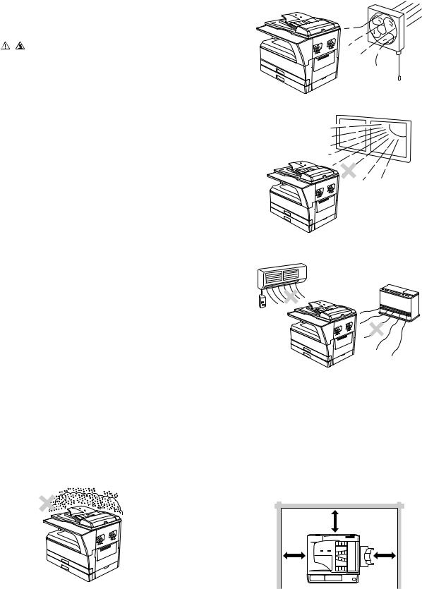
Do not install your machine in areas that are:
•damp, humid, or very dusty
•poorly ventilated
•exposed to direct sunlight
•subject to extreme temperature or humidity changes, e.g., near an air conditioner or heater.
The machine should be installed near an accessible power outlet for easy connection and disconnection.
Be sure to connect the power cord only to a power outlet that meets the specified voltage and current requirements. Also make certain the outlet is properly grounded.
Note : Connect the machine to a power outlet which is not used for other electric appliances. If a lighting fixture is connected to the same outlet, the light may flicker.
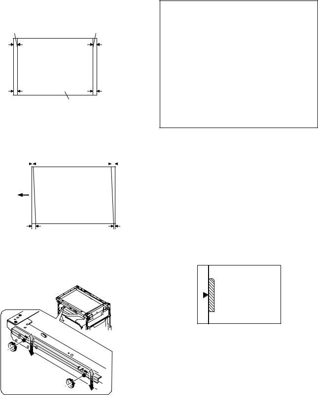
Be sure to allow the required space around the machine for servicing and proper ventilation.
|
20 cm (8″) |
|
|
20 cm |
20 cm |
|
(8″) |
(8″) |
AR-5520 GENERAL 1-1
[2] CONFIGURATION
1. System Configurations
AR-SP10
|
AR-5520/AR-5520S |
AR-5516/AR-5516S |
AR-RP10
|
Model |
AR-5520 / AR-5520S |
AR-5520D |
Remark |
||
|
Option |
AR-5516 /AR-5516S |
AR-5516D |
|||
|
AR-RP10 |
Duplex document auto feeder (RSPF) |
X |
O |
||
|
AR-SP10 |
Document auto feeder (SPF) |
O |
X |
||
|
AR-D34 |
1-stage paper feed unit |
O |
O |
||
|
AR-D35 |
2-stage paper feed unit |
O |
O |
||
|
O:Option installation enable |
X: Option installation disable |
AR-5520 CONFIGURATION 2-1
[3] SPECIFICATIONS
1. Copy mode
A. Type
|
Type |
Desk-top |
|
Paper exit |
Wing less |
B. Machine composition
|
AR-5516 / AR-5516S / AR-5516D |
16-CPM multi function model |
|
AR-5520 / AR-5520S / AR-5520D |
20-CPM multi function model |
(1) Option
|
Machine |
Model |
|
|
250 sheets paper feed unit |
AR-D34 |
|
|
250 sheets x 2 paper feed unit |
AR-D35 |
|
|
SPF |
AR-SP10 |
AR-5520/ AR-5520S |
|
AR-5516 /AR-5516S |
||
|
RSPF |
AR-RP10 |
AR-5520D/ AR-5516D |
C. Copy speed
(1) Engine speed (ppm)
|
Paper size |
AR-5520 / AR-5520S |
AR-5516 / AR-5516S |
|
|
AR-5520D |
AR-5516D |
||
|
A4/ 8.5”x11” |
20ppm |
16ppm |
|
|
A4R |
14ppm |
12ppm |
|
|
8.5”x11”R |
15ppm |
12ppm |
|
|
A5/ 5.5”x8.5” |
20ppm |
16ppm |
|
|
B5/ 16K |
20ppm |
16ppm |
|
|
B5R |
16ppm |
14ppm |
|
|
16KR |
15ppm |
14ppm |
|
|
8.5×13” |
12ppm |
11ppm |
|
|
B4/ 8.5”x14 |
12ppm |
10ppm |
|
|
A3 |
11ppm |
9ppm |
|
|
11”x17” |
10ppm |
9ppm |
|
|
8K |
11ppm |
10ppm |
|
(2) Document replacement speed (Copy mode)
|
Copy mode |
AR-5520 / AR-5520S |
AR-5516 / AR-5516S |
||
|
AR-5520D |
AR-5516D |
|||
|
S to S |
20cpm |
(100%) |
16cpm |
(100%) |
|
S to D |
9cpm |
(45%) |
9cpm |
(56%) |
|
D to D |
8cpm |
(40%) |
8cpm |
(50%) |
S to S : Tray1 A4/8.5”X11” document 11 sheets (11 pages), copy 1 set S to D : Tray1 A4/8.5”X11” document 22 sheets (22 pages), copy 1 set D to D : Tray1 A4/8.5”X11” document 11 sheets (22 pages), copy 1 set
(3) Job efficiency
|
Copy mode |
AR-5520 / AR-5520S |
AR-5516 / AR-5516S |
|
|
AR-5520D |
AR-5516D |
||
|
S to S |
19cpm (95%) |
15cpm (94%) |
|
|
S to D |
11cpm (55%) |
10cpm (63%) |
|
|
D to D |
10cpm (50%) |
10cpm (63%) |
|
S to S : Tray1 A4/8.5”X11” document 10 sheets (10 pages), copy 5 sets S to D : Tray1 A4/8.5”X11” document 10 sheets (10 pages), copy 5 sets D to D : Tray1 A4/8.5”X11” document 10 sheets (20 pages), copy 5 sets
(4) First copy time
|
Tray |
Content |
|
1st tray |
7.2 sec or less |
|
2nd tray |
8.5 sec or less |
|
3rd tray |
9.5 sec or less |
|
4th tray |
10.5 sec or less |
|
Bypass tray |
7.5 sec or less |
600x300dpi, AE mode, A4/Letter, single surface copy with OC, in polygon ready state
D. Document
|
Max. document size |
A3, 11″ X 17″ |
|
Document reference position |
Left side center |
|
Detection (Platen) |
None |
E. Paper feed
(1) Paper feed section details
|
Item |
1st tray |
2nd tray |
Bypass tray |
|
|
Paper capacity |
250 |
250 |
100 sheets |
|
|
sheets |
sheets |
|||
|
Paper size detection |
No |
|||
|
(Paper size is set with |
||||
|
the system setting.) |
||||
|
Paper type setting |
No |
No |
No |
|
|
(Heavy |
||||
|
paper setting |
||||
|
is enabled.) |
||||
|
Paper size changing method |
The paper |
guide is set |
by the user. |
|
|
Paper when shipping |
AB series |
A4 |
A4 |
— |
|
Size setting |
Inch series |
8 1/2” x11” |
8 1/2” x11” |
— |
|
Remaining paper quantity |
Only empty detection available |
|||
|
detection |
||||
(2) Feedable paper
|
Paper size |
1st tray |
2nd tray |
Bypass |
|
|
tray |
||||
|
A3 |
297×420 |
Yes |
Yes |
Yes |
|
B4 |
257×364 |
Yes |
Yes |
Yes |
|
A4 |
297×210 |
Yes |
Yes |
Yes |
|
A4-R |
210×297 |
Yes |
Yes |
Yes |
|
B5 |
257×182 |
Yes |
Yes |
Yes |
|
B5R |
182×257 |
Yes |
Yes |
Yes |
|
A5 |
210×148.5 |
Yes |
N/A |
Yes |
|
A5R |
148.5×210 |
N/A |
N/A |
Yes |
|
A6R |
105×148.5 |
N/A |
N/A |
Yes |
|
B6R |
128.5×182 |
N/A |
N/A |
Yes |
|
Ledger 11 x 17 in |
279.4×431.8 |
Yes |
Yes |
Yes |
|
Legal 8.5x14in. |
215.9×355.6 |
Yes |
Yes |
Yes |
|
Foolscap 8.5 x 13 in |
215.9×330.2 |
Yes |
Yes |
Yes |
|
Letter 11×8.5in |
279.4×215.9 |
Yes |
Yes |
Yes |
|
Letter-R 8.5x11in |
215.9×279.4 |
Yes |
Yes |
Yes |
|
Executive-R 7.25×10.5in. |
184.2×266.7 |
N/A |
N/A |
Yes |
|
Invoice 8.5×5.5 in. |
215.9×139.7 |
Yes |
N/A |
Yes |
|
Invoice-R 5.5×8.5 in |
139.7×215.9 |
N/A |
N/A |
Yes |
|
8K |
270×390 |
Yes |
Yes |
Yes |
|
16K |
270×195 |
Yes |
Yes |
Yes |
|
16KR |
195×270 |
Yes |
Yes |
Yes |
|
COM10 |
104.8×241.3 |
N/A |
N/A |
Yes |
|
COM9 |
98.4×225.4 |
N/A |
N/A |
Yes |
|
C5 |
162×229 |
N/A |
N/A |
Yes |
|
DL |
110×220 |
N/A |
N/A |
Yes |
|
Postcard |
100×148 |
N/A |
N/A |
Yes |
|
Return postcard |
200×148 |
N/A |
N/A |
Yes |
|
Long format No. 3 |
120.1×235 |
N/A |
N/A |
Yes |
|
Monarch |
98.4×190.5 |
N/A |
N/A |
Yes |
|
Western format No. 2 |
114×162 |
N/A |
N/A |
Yes |
|
Western format No. 4 |
105×235 |
N/A |
N/A |
Yes |
AR-5520 SPECIFICATIONS 3-1
(3)Types of feedable paper
|
Types of paper |
1st tray |
2nd tray |
Bypass tray |
||
|
Thin paper |
56-59g/m2 |
Yes |
Yes |
Yes |
|
|
15-15.9lbs |
|||||
|
Plain paper |
60-90g/m2 |
Yes |
Yes |
Yes |
|
|
16-24lbs |
(Multi paper feed enable) |
||||
|
Heavy paper |
91-105g/m2 |
N/A |
N/A |
Yes |
|
|
16-24lbs |
(Multi paper feed enable) |
||||
|
106-128g/m2 |
Yes |
||||
|
Heavy paper |
N/A |
N/A |
(A4 or less) |
||
|
24.1-33.5lbs |
|||||
|
(Multi paper feed enable) |
|||||
|
129-200g/m2 |
Yes |
||||
|
Heavy paper |
N/A |
N/A |
(A4 or less) |
||
|
33.6-53.2lbs |
|||||
|
(Only single paper feed) |
|||||
|
Heavy paper |
201-256g/m2 |
N/A |
N/A |
N/A |
|
|
53.3-68lbs |
|||||
|
Envelope |
75-90g/m2 |
N/A |
N/A |
Yes |
|
|
20-24lbs |
|||||
|
Postcard |
N/A |
N/A |
Yes |
||
|
OHP film |
N/A |
N/A |
Yes |
||
|
Label sheet |
N/A |
N/A |
Yes |
||
|
Tab paper 20 |
N/A |
N/A |
Yes |
||
F. Multi copy
|
Max. number of multi copy |
999 sheets |
G. Warm-up time
|
Warm-up time |
45 sec |
|
Pre-heat |
Available |
|
Jam recovery |
Within 45 sec |
H. Copy magnification ratio
|
Fixed |
AB system: |
|
magnification |
50,70,86,100,141,200% |
|
ratio |
|
|
Inch system: |
|
|
50,64,78,100,129,200% |
|
|
Zooming |
25 ~ 400% |
|
SPF/RSPF(50 ~ 200%) |
|
|
Independent |
Available (25 ~ 400%) |
|
zooming(vertical) |
SPF/RSPF(50 ~ 200%) |
|
Independent zooming |
Available (25 ~ 400%) |
|
(horizontal) |
SPF/RSPF(50 ~ 200%) |
I. Print density
|
Density mode |
Auto / Text / Photo |
|
No. of manual |
5 steps (Text / Photo) |
|
adjustment |
|
|
Resolution |
Writing: 600 x 600dpi |
|
Reading: 600 (main) x 600 (sub) (PHOTO mode) |
|
|
600 (main) x 300 (sub) (AUTO exposure |
|
|
mode) |
|
|
Gradation |
Reading: 256 gradations |
|
Writing: Binary |
|
|
Toner save mode |
Set by the user program |
J. Void width
|
Void area |
Lead edge 1 ~ 4mm, |
||
|
rear edge 4mm or less, |
|||
|
Total of both sides: 6mm or less |
|||
|
Image loss |
OC |
Same size |
3.0mm or less |
|
Enlargement |
1.5mm or less |
||
|
Reduction |
6.0mm or less |
||
|
SPF/RSPF |
Same size |
4.0mm or less |
|
|
Enlargement |
3.0mm or less |
||
|
Reduction |
8.0mm or less |
||
K. Auto duplex
|
Standard/ |
Standard provision (AR-5520D / AR-5516D only) |
|
Option |
(D→ D / D → S enable only when RSPF is installed) |
|
Not available for AR-5520 / AR-5520S / AR-5516/ AR- |
|
|
5516S |
|
L. Paper exit / finishing
|
Paper exit section |
Face down 250 sheets |
|
capacity |
|
|
Full detection |
None |
|
Finishing |
None |
|
Electronic sort |
A4/ 8.5″ x 11″ standard document (6% |
|
capacity |
coverage) 160 sheets |
|
Offset function |
None |
|
Staple function |
None |
M. Additional functions
|
AR-5520S |
AR-5520 |
AR-5520D |
|||||
|
AR-5516S |
AR-5516 |
AR-5516D |
|||||
|
APS |
O |
||||||
|
AMS |
O |
||||||
|
Auto tray |
O |
||||||
|
switching |
|||||||
|
Memory copy |
O |
||||||
|
Rotation copy |
O |
||||||
|
E-sort (Sorting |
O |
||||||
|
function) |
X |
Single surface, A4, 6% document, Max. |
|||||
|
160 sheets |
|||||||
|
E-sort (Grouping |
X |
O |
|||||
|
function) |
|||||||
|
Rotation sort |
X |
||||||
|
Prevention of sky |
X |
||||||
|
shot |
|||||||
|
Independent |
O |
||||||
|
zooming |
|||||||
|
1 set 2 copy |
O |
||||||
|
Disable in enlargement copy or when SPF/RSPF is |
|||||||
|
used. |
|||||||
|
Binding margin |
O |
||||||
|
X |
Default AB series: 10mm (5, 10, 15, 20mm) |
||||||
|
Inch series: 1/2 inch (1/4, 1/2, 3/4, 1 inch) |
|||||||
|
Edge erase |
O |
||||||
|
X |
Default AB series: 10mm (5, 10, 15, 20mm) |
||||||
|
Inch series: 1/2 inch (1/4, 1/2, 3/4, 2 inch) |
|||||||
|
Center erase |
O |
||||||
|
X |
Default AB series: 10mm (5, 10, 15, 20mm) |
||||||
|
Inch series: 1/2 inch (1/4, 1/2, 3/4, 3 inch) |
|||||||
|
Black/white |
X |
||||||
|
reverse |
|||||||
|
2in1/4in1 |
X |
O |
|||||
|
Offset |
X |
||||||
|
Preheating |
O |
The conditions are set by the user program. |
|||||
|
Auto shut-off |
O |
The conditions are set by the user program. |
|||||
|
User |
O |
||||||
|
programming |
|||||||
|
Total counter |
O |
Supports Total counter |
and Copy counter. |
||||
|
Coin vendor |
O |
(Supports I/F only.) |
|||||
|
support |
|||||||
|
Auditor support |
O |
(Supports I/F only.) |
|||||
|
Duplex |
X |
O |
|||||
|
Toner save |
O (Set according to the destination) |
||||||
|
Department |
O (Copy: 20 Dept.) |
||||||
|
management |
|||||||
|
O : Available X |
: Not available |
AR-5520 SPECIFICATIONS 3-2
N. Other specifications
|
Photoconductor type |
OPC (Organic Photo Conductor) |
|
Photoconductor drum dia. |
30mm |
|
Copy lamp |
Cold cathode fluorescent lamp (CCFL) |
|
Developing system |
Dry 2-component magnetic brush |
|
development |
|
|
Charging system |
Saw teeth charging |
|
Transfer system |
(+) DC corotron |
|
Separation system |
(-) DC corotron |
|
Fusing system |
Heat roller |
|
Cleaning system |
Contact blade |
O. Package form
P. External view
|
AR-5520S/AR-5520/ |
AR-5516S/AR-5516/ |
||
|
AR-5520D |
AR-5516D |
||
|
External dimensions |
590mm(W) x 550mm(D) |
590mm(W) x 550mm(D) |
|
|
(With the bypass tray |
|||
|
x 555mm(H) or less |
x 470mm(H) or less |
||
|
closed) |
|||
|
Occupying area |
|||
|
(With the bypass tray |
883mm(W) x 550mm(D) or less |
||
|
opened) |
|||
|
Weight |
|||
|
(Excluding |
35.9Kg |
30.9Kg |
|
|
developer) |
|||
Q. Power source
|
Voltage |
100 — 127V 220 — 240V |
|
Frequency |
50/60Hz common |
R. Power consumption
|
Max. power consumption |
1200W |
||
|
* EnergyStar conformity |
|||
|
Average power consumption in |
Less than 550W |
||
|
operation |
|||
|
Power consumption when |
5W(Not include option) |
||
|
standby |
|||
|
Energy consumption efficiency |
Less than 25W |
||
|
S. Digital performance |
|||
|
Resolution |
Reading |
600 x 600dpi (PHOTO mode) |
|
|
600 x 300dpi (AUTO exposure mode) |
|||
|
Writing |
600 x 600dpi |
||
|
Gradation |
Reading |
256 gradations |
|
|
Writing |
Binary |
||
|
Memory |
AR-5520S/5516S : 16MB |
||
|
AR-5520/5516/5520D/5516D : 64MB |
|||
|
Hard disk |
None |
||
T. Printing function
(1) Platform
|
Item |
Content |
|
Support platform |
IBM PC/AT compatible machine |
(2) Support OS
|
OS |
Support |
|
Windows 95 |
X |
|
Windows 98/Me |
X |
|
Windows NT 4.0 SP5 |
X |
|
Windows 2000 |
O |
|
Windows XP 32 |
O |
|
Windows XP 64 |
O (Web release only) |
|
Windows Server 2003 |
X |
|
Windows Vista 32 |
O |
|
Windows Vista 64 |
O (Web release only) |
AR-5520 SPECIFICATIONS 3-3
(3) Printer driver function (SPLC)
|
Item |
SPLC |
|||
|
Common |
Default |
Button |
||
|
MIMIC |
Yes |
|||
|
Configuration |
Input Tray Options |
One Tray/ Two Tray/ Three Tray/ |
||
|
Four Tray |
||||
|
Set |
Paper |
Tray1/ Tray2/ Bypass Tray |
||
|
Tray |
Source |
|||
|
Status |
||||
|
Set Paper |
Not set/ A3/ A4-R/ A5-R/ A6-R/ B4/ |
|||
|
size |
B5-R/ B6-R/ Leger/ Letter-R/ |
|||
|
Legal/ Executive-R/ Invoice-R/ |
||||
|
Foolscap/ Folio/ Com10/ DL/ C5/ |
||||
|
8k/ 16k-R/ Custom paper |
||||
|
ROPM |
On/Off (The AR-5520S/5516S are |
|||
|
out of target.) |
||||
|
Status window |
Button |
|||
|
About |
Button |
|||
|
Main |
Copies |
1-999 |
||
|
Collate |
On/ Off |
|||
|
N-UP printing |
1/ 2/ 4 /6 up |
|||
|
User settings |
Button |
|||
|
Paper |
Paper size |
A3/ A4/ A5/ A6/ B4/ B5/ B6/ Leger/ |
||
|
Letter/ Legal/ Executive/ Invoice/ |
||||
|
Foolscap/ Folio/ Com10/ DL/ C5/ |
||||
|
8k/ 16k/ Custom paper |
||||
|
— Custom paper: |
||||
|
Width [100.0] -[297.0] |
||||
|
[3.94”] -[11.69”] |
||||
|
Length [148.0] -[431.8] |
||||
|
[5.83”] — [17.00”] |
||||
|
— Milimeters/ Inches |
||||
|
Fit to paper size |
On/Off |
|||
|
A3/ A4/ A5/ A6/ B4/ B5/ B6/ Leger/ |
||||
|
Letter/ Legal/ Executive/ Invoice/ |
||||
|
Foolscap/ Folio/ Com10/ DL/ C5/ |
||||
|
8k/ 16k |
||||
|
Image orientation |
Portrait/ Landscape/ Rotate 180 |
|||
|
degrees |
||||
|
Paper selection |
Auto select/ Tray1/ Tray2/ Bypass |
|||
|
Tray |
||||
|
Advanced |
Image quality |
Draft/ Normal/ Photo |
||
|
Text to Black, Vector |
On/Off |
|||
|
to Black |
||||
|
Watermark |
Watermark |
Top seclet/ Confidential/ Draft/ |
||
|
Original/ Copy |
||||
|
Text |
Yes |
|||
|
Size |
[6] — [300] |
|||
|
Angle |
[-90] — [90] |
|||
|
Grayscale |
[0] — [255] |
|||
|
Edit font |
Yes |
|||
|
On first page only |
On/Off |
|||
|
Center |
Button |
|||
|
Position |
X: [-50] — [50] |
|||
|
Y: [-50] — [50] |
||||
U. Scanner function (Except for AR-5520/AR-5516)
|
Type |
Flat bed scanner |
|
|
Scan system |
Document table/document feed unit |
|
|
Light source |
Yellow + Green CCFL |
|
|
Resolution |
Binary: 600 x 600 dpi |
|
|
Gray scale: 300 x 300 dpi |
||
|
Document |
Sheet/Book |
|
|
Effective scan range |
OC/SPF/RSPF: |
|
|
about 297(length) x 431(width) mm |
||
|
Scan speed |
OC/SPF/R-SPF: |
|
|
0.962msec/line(300 dpi) |
||
|
Input data |
1bit or 12bit |
|
|
Output data |
1bit or 8bit |
|
|
Scan color |
Black & white / binary / Gray scale |
|
|
Protocol |
TWAIN / WIA(XP only) * / STI |
|
|
Interface |
USB2.0 (High speed mode, full speed mode) |
|
|
Scanner utility |
Button Manager |
|
|
Drop-out color |
No |
|
|
Scanner button |
Provided (6) |
|
|
Supported OS |
USB connection:Windows 2000/XP/VISTA |
|
|
network connection:Windows 2000/XP/VISTA |
||
|
Void area |
Lead edge/rear edge (2.5mm) on the driver |
|
|
side Left/right: 3.0mm |
||
|
WHQL support |
No |
|
AR-5520 SPECIFICATIONS 3-4
[4] CONSUMABLE PARTS
1.Supply system table
A. USA/Canada/South and Central America(100V series)
AR-5516/AR-5520D
|
No. |
Name |
Product name |
Content |
Life |
Remark |
|
|
1 |
Toner cartridge(Black) |
AR-020MT |
Toner cartridge |
x10 |
160K(16Kx10) |
Life setting by A4 6% document |
|
(AR-020NT x 10) |
(Toner:Net 537g With IC) |
|||||
|
2 |
Developer |
AR-205MD |
Developer |
x10 |
500K(50×10) |
|
|
(AR-205ND x 10) |
(Net 300g) |
|||||
|
3 |
Drum KIT |
AR-205DR |
Drum |
x1 |
50K |
|
|
Drum fixing plate |
x1 |
|||||
B. South and Central America(200V series)
AR-5516/AR-5520D
|
No. |
Name |
Product name |
Content |
Life |
Remark |
|
|
1 |
Toner cartridge(Black) |
AR-020LT |
Toner cartridge |
x10 |
190K(19Kx10) |
Life setting by A4 6% document |
|
(AR-020T x 10) |
(Toner:Net 537g With IC) |
(In a toner save mode) |
||||
|
2 |
Developer |
AR-205LD |
Developer |
x10 |
500K(50×10) |
|
|
(AR-205DV x 10) |
(Net 300g) |
|||||
|
3 |
Drum KIT |
AR-205DM |
Drum |
x1 |
50K |
|
|
Drum fixing plate |
x1 |
|||||
C. Brazil
AR-5516/AR-5520D
|
No. |
Name |
Product name |
Content |
Life |
Remark |
|
|
1 |
Toner cartridge(Black) |
AR-020MTB |
Toner cartridge |
x10 |
190K(19Kx10) |
Life setting by A4 6% document |
|
(AR-020NTB x 10) |
(Toner:Net 537g With IC) |
(In a toner save mode) |
||||
|
2 |
Developer |
AR-205MD |
Developer |
x10 |
500K(50×10) |
|
|
(AR-205ND x 10) |
(Net 300g) |
|||||
|
3 |
Drum KIT |
AR-205DR |
Drum |
x1 |
50K |
|
|
Drum fixing plate |
x1 |
|||||
D. Europe
AR-5516/AR-5516S/AR-5520/AR-5520S/AR-5520D
|
No. |
Name |
Product name |
Content |
Life |
Remark |
|
|
1 |
Toner cartridge(Black) |
AR-020LT |
Toner cartridge |
x10 |
160K(16Kx10) |
Life setting by A4 6% document |
|
(AR-020T x 10) |
(Toner:Net 537g With IC) |
(In a toner save mode) |
||||
|
2 |
Developer |
AR-205LD |
Developer |
x10 |
500K(50×10) |
|
|
(AR-205DV x 10) |
(Net 300g) |
|||||
|
3 |
Drum KIT |
AR-205DM |
Drum |
x1 |
50K |
|
|
Drum fixing plate |
x1 |
|||||
E. Australia/New Zealand
AR-5516/AR-5516D/AR-5520/AR-5520S/AR-5520D
|
No. |
Name |
Product name |
Content |
Life |
||
|
1 |
Toner cartridge(Black) |
AR-020LT |
Toner cartridge |
x10 |
190K(19Kx10) |
Life setting by A4 6% document |
|
(AR-020T x 10) |
(Toner:Net 537g With IC) |
(In a toner save mode) |
||||
|
2 |
Developer |
AR-205LD |
Developer |
x10 |
500K(50×10) |
|
|
(AR-205DV x 10) |
(Net 300g) |
|||||
|
3 |
Drum KIT |
AR-205DM |
Drum |
x1 |
50K |
|
|
Drum fixing plate |
x1 |
|||||
AR-5520 CONSUMABLE PARTS 4-1
F. Middle East/Africa/Israel/Philippine/Other Distributor
AR-5516/AR-5516S/AR-5516D/AR-5520/AR-5520S/AR-5520D
|
No. |
Name |
Product name |
Content |
Life |
Remark |
||
|
1 |
Toner cartridge(Black) |
AR-021ET |
Toner cartridge |
x10 |
190K(19Kx10) |
Life setting by A4 6% document |
|
|
(AR-021FT |
x 10) |
(Toner:Net 537g With IC) |
(In a toner save mode) |
||||
|
2 |
Developer |
AR-205CD |
Developer |
x10 |
500K(50×10) |
||
|
(AR-205SD |
x 10) |
(Net 300g) |
|||||
|
3 |
Drum KIT |
AR-205DR |
Drum |
x1 |
50K |
||
|
Drum fixing plate |
x1 |
||||||
G. Taiwan
AR-5516/AR-5516S/AR-5516D/AR-5520/AR-5520S/AR-5520D
|
No. |
Name |
Product name |
Content |
Life |
Remark |
||
|
1 |
Toner cartridge(Black) |
AR-021ET |
Toner cartridge |
x10 |
160K(16Kx10) |
Life setting by A4 6% document |
|
|
(AR-021FT |
x 10) |
(Toner:Net 537g With IC) |
|||||
|
2 |
Developer |
AR-205CD |
Developer |
x10 |
500K(50×10) |
||
|
(AR-205SD |
x 10) |
(Net 300g) |
|||||
|
3 |
Drum KIT |
AR-205DR |
Drum |
x1 |
50K |
||
|
Drum fixing plate |
x1 |
||||||
H. Asia(Except the above)
AR-5516/AR-5516S/AR-5516D/AR-5520/AR-5520S/AR-5520D
|
No. |
Name |
Product name |
Content |
Life |
Remark |
||
|
1 |
Toner cartridge(Black) |
AR-020CT |
Toner cartridge |
190K(19Kx10) |
Life setting by A4 6% document |
||
|
(AR-020ST |
x 10) |
(Toner:Net 537g With IC) |
x10 |
(In a toner save mode) |
|||
|
2 |
Developer |
AR-205CD |
Developer |
x10 |
500K(50×10) |
||
|
(AR-205SD |
x 10) |
(Net 300g) |
|||||
|
3 |
Drum KIT |
AR-205DR |
Drum |
x1 |
50K |
||
|
Drum fixing plate |
x1 |
||||||
AR-5520 CONSUMABLE PARTS 4-2
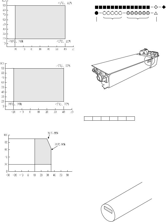
2. Environmental conditions
A. Transport conditions
(1) Transport conditions
Temperature 

|
(2) Storage conditions |
|
Humidity (%) |
Temperature 

3. Production number identification
<Toner cartridge>
The label on the toner cartridge shows the date of production.
|
Production |
Serial |
Year/ |
Ver.No. |
|
place |
number |
Month/ |
|
|
Day |
<Drum cartridge>
The lot number, printed on the front side flange, is composed of 6 digits, each digit showing the following content:
|
1 |
2 |
3 |
4 |
5 |
6 |
B. Use conditions
1Alphabet
Indicates the model conformity code. A for this model.
|
2 |
Number |
||
|
Indicates the end digit of the production year. |
|||
|
(%) |
3 |
Number or X, Y, Z |
|
|
Use envi- |
Indicates the month of packing. |
||
|
Humidity |
ronment |
Indicates the day of the month of packing. |
|
|
X stands for October, Y November, and Z December. |
|||
|
conditions |
4/5 |
Number |
|
|
6 |
Alphabet |
||
|
Indicates the production factory. «A» for Nara Plant, “C“ for |
|||
|
SOCC |
Temperature 

C. Life(packed conditions)
Photoconductor drum (36 months from the production month)
Developer, toner (24 months from the production month)
AR-5520 CONSUMABLE PARTS 4-3

[5] EXTERNAL VIEWS AND INTERNAL STRUCTURES
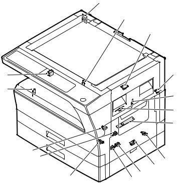
1. Appearance
|
9 |
12 |
13 |
14 |
|||||
|
1 |
Glass cleaner |
2 |
Document feeder cover (when the SPF/ |
3 |
Document glass |
|||
|
(when the SPF/RSPF is installed) |
RSPF is installed) /document cover |
|||||||
|
4 |
Handles |
5 |
Power switch |
6 |
Operation panel |
|||
|
7 |
Paper output tray |
8 |
Front cover |
9 |
Paper trays |
|||
|
10 |
Side cover |
11 |
Side cover handle |
12 |
Bypass tray guides |
|||
|
13 |
Bypass tray |
14 |
Bypass tray extension |
15 |
Charger cleaner |
|||
|
16 |
USB 2.0 connector |
|||||||
2. Internal |
||||||||
|
17 18 |
19 |
22
|
24 |
25 |
26 |
27 |
||||
|
23 |
|||||||
|
17 |
Document feeder tray |
18 |
Original guides |
19 |
Feeding roller cover |
||
|
(when the SPF/RSPF is installed) |
(when the SPF/RSPF is installed) |
(when the SPF/RSPF is installed) |
|||||
|
20 |
Right side cover |
21 |
Exit area |
22 |
Toner cartridge lock release lever |
||
|
(when the SPF/RSPF is installed) |
(when the SPF/RSPF is installed) |
||||||
|
23 |
Toner cartridge |
24 |
Roller rotating knob |
25 |
Fusing unit release levers |
||
|
26 |
Photoconductive drum |
27 |
Fusing unit paper guide |
AR-5520 EXTERNAL VIEWS AND INTERNAL STRUCTURES 5-1
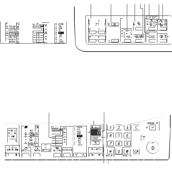
3. Operation Section
|
The indications of the operation panel may differ |
1 |
2 |
3 |
4 |
5 |
6 |
7 |
8 |
9 |
10 |
11 |
|||||||||||||||||
|
depending on the country and the region. |
||||||||||||||||||||||||||||
The example of a display of inch series.
|
13 |
14 |
15 |
26 |
27 |
||||||||||||||||||||||||||
|
1 |
SCAN MENU key |
2 |
SCAN key / indicator |
3 |
ON LINE key/indicator |
|||||||||||||||||||||||||
|
(Except AR-5516S/AR-5520S) |
(Except AR-5516S/AR-5520S) |
|||||||||||||||||||||||||||||
|
4 |
ORIGINAL TO COPY key/indicators |
5 |
XY-ZOOM key / indicator |
6 |
DUAL PAGE COPY key / indicator |
|||||||||||||||||||||||||
|
(Except AR-5516/AR-5520/AR-5516S/ |
||||||||||||||||||||||||||||||
|
AR-5520S) |
||||||||||||||||||||||||||||||
|
7 |
ERASE key / indicators |
8 |
ORIGINAL DATA indicator |
9 |
SORT/GROUP key / indicators |
|||||||||||||||||||||||||
|
(Except AR-5516S/AR-5520S) |
(Except AR-5516S/AR-5520S) |
|||||||||||||||||||||||||||||
|
10 |
2 IN 1 / 4 IN 1 key / indicators |
11 |
MARGIN SHIFT key / indicator |
|||||||||||||||||||||||||||
|
(Except AR-5516S/AR-5520S) |
(Except AR-5516S/AR-5520S) |
|||||||||||||||||||||||||||||
|
12 |
13 |
14 |
15 |
16 |
17 |
18 |
19 |
20 |
||||||||||||||||||||||
|
21 |
22 |
24 |
25 |
26 |
27 |
28 |
29 30 31 |
32 |
33 |
34 |
35 |
|||||||||||||||
|
23 When there are two or more paper trays |
||||||||||||||||||||||||||
|
12 |
AUTO/TEXT/PHOTO key / indicators |
13 |
ORIGINAL key / ORIGINAL SIZE |
14 |
PAPER SIZE indicators |
|||||||||||||||||||||
|
indicators |
||||||||||||||||||||||||||
|
15 |
Paper feed location / misfeed location |
16 |
Alarm indicators |
17 |
Display |
|||||||||||||||||||||
|
indicators |
||||||||||||||||||||||||||
|
18 |
Numeric keys |
19 |
CLEAR key |
20 |
INTERRUPT key / indicator |
|||||||||||||||||||||
|
21 |
Light and Dark keys / indicators |
22 |
PAPER SELECT key |
23 |
AUTO PAPER SELECT indicator |
|||||||||||||||||||||
|
24 |
TRAY SETTING key |
25 |
AUTO IMAGE key / indicator |
26 |
SPF/RSPF indicator |
|||||||||||||||||||||
|
(when the SPF/RSPF is installed) |
||||||||||||||||||||||||||
|
27 |
PRESET RATIO selector keys / |
28 |
Zoom keys |
29 |
Copy ratio display key |
|||||||||||||||||||||
|
indicators |
||||||||||||||||||||||||||
|
30 |
ZOOM indicator |
31 |
Audit clear key |
32 |
READ-END key |
|||||||||||||||||||||
|
33 |
CLEAR ALL key |
34 |
POWER SAVE indicator |
35 |
START key / indicator |
AR-5520 EXTERNAL VIEWS AND INTERNAL STRUCTURES 5-2

4. Motor, solenoid, clutch
|
1 |
||
|
2 |
||
|
18 |
||
|
3 |
||
|
4 |
||
|
5 |
||
|
17 |
6 |
|
|
7 |
||
|
8 |
||
|
9 |
||
|
10 |
||
|
11 |
||
|
12 |
||
|
13 |
||
|
14 |
||
|
16 15 |
|
No. |
Name |
Code |
Function operation |
|
1 |
Mirror motor |
MRM |
Drives the optical mirror base (scanner unit). |
|
2 |
Toner motor |
TM |
Toner supply |
|
3 |
Duplex motor |
DPX |
Switchback operation and paper exit motor in duplex. |
|
4 |
Cooling fan motor |
CFM |
Cools the inside of the machine. |
|
5 |
Main motor |
MM |
Drives the machine. |
|
6 |
1st tray paper feed clutch |
CPFC1 |
Drive the pick up roller |
|
7 |
PS clutch |
RRC |
Drives the resist roller |
|
8 |
Paper feed solenoid |
CPSOL1 |
Solenoid for paper feed from tray |
|
9 |
Resist roller solenoid |
RRS |
Resist roller rotation control solenoid |
|
10 |
Bypass tray paper transport clutch |
MPTC |
Drives the bypass tray paper transport roller. |
|
11 |
Bypass tray paper feed clutch |
MPFC |
Drives the bypass tray paper feed roller. |
|
12 |
Bypass tray paper feed solenoid |
MPFS |
Bypass tray paper feed solenoid |
|
13 |
2nd tray transport clutch |
CPFC2 |
Drives the 2nd tray transport roller. |
|
14 |
2nd tray transport solenoid |
FSOL1 |
2nd tray transport solenoid |
|
15 |
2nd tray paper feed clutch |
CPFC1 |
Drives the 2nd tray paper feed roller. |
|
16 |
2nd tray paper feed solenoid |
PSOL2 |
2nd tray transport solenoid |
|
17 |
Exhaust fan motor |
VFM |
Cools the inside of the machine. |
|
18 |
Cooling fan motor |
CFM |
Cools the inside of the machine. |
AR-5520 EXTERNAL VIEWS AND INTERNAL STRUCTURES 5-3
5. Sensor, switch
|
1 |
|
|
2 |
|
|
3 |
|
|
16 |
4 |
|
15 |
5 |
|
6 |
|
|
7 |
14
|
13 |
8 |
||||
|
9 |
|||||
|
12 |
11 |
10 |
|||
|
No. |
Name |
Code |
Function operation |
||
|
1 |
Mirror home position sensor |
MHPS |
Detects the mirror (scanner unit) home position. |
||
|
2 |
Side door switch |
DSWR |
Side door open detection |
||
|
3 |
Paper exit sensor (paper exit side) |
POD1 |
Detects paper exit. |
||
|
4 |
Paper exit sensor (DUP side) |
PDPX |
Paper transport detection |
||
|
5 |
Thermistor |
RTH |
Fusing section temperature detection |
||
|
6 |
Thermostat |
Fusing section abnormally high temperature detection |
|||
|
7 |
Toner density sensor |
TCS |
Toner quantity detection |
||
|
8 |
2nd tray detection switch |
2nd tray detection |
|||
|
9 |
Bypass tray sensor |
MPED |
Bypass tray transport detection |
||
|
10 |
2nd tray door open/close sensor |
DRS2 |
2nd tray door open/close detection |
||
|
11 |
2nd tray door paper pass sensor |
PPD2 |
2nd tray paper entry detection |
||
|
12 |
2nd tray paper empty sensor |
CSS2 |
2nd tray paper empty detection |
||
|
13 |
Paper in sensor |
PIN |
Paper transport detection |
||
|
14 |
Tray empty |
Tray paper entry detection |
|||
|
15 |
Front cover SW |
Front cover open detection |
|||
|
16 |
Power switch |
MAIN SW |
Turns ON/OFF the main power source. |
AR-5520 EXTERNAL VIEWS AND INTERNAL STRUCTURES 5-4
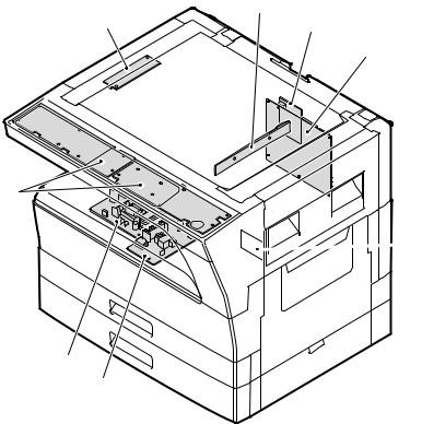
6. PWB unit
2
3
7

 4
4
6
5
|
No. |
Name |
Function operation |
|
1 |
Copy lamp Inverter PWB |
Copy lamp control |
|
2 |
CCD sensor PWB |
Image scanning |
|
3 |
Main control PWB |
Main control PWB |
|
4 |
2nd tray PWB |
2nd tray control |
|
5 |
High voltage PWB |
High voltage control |
|
6 |
Power PWB |
AC power input/DC power control |
|
7 |
Operation main PWB |
Operation panel input/Display, operation panel section control |
|
8 |
USB I/F PWB |
Connect a USB device |
AR-5520 EXTERNAL VIEWS AND INTERNAL STRUCTURES 5-5
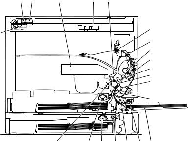
7. Cross sectional view
|
1 |
2 |
3 |
4 |
5 |
6
18
7 8
9
10
11
12


 13
13
 14 15
14 15
|
23 |
22 |
21 |
20 |
19 |
17 |
16 |
|
|
No. |
Name |
Function/Operation |
|||||
|
1 |
Copy lamp |
Image radiation lamp |
|||||
|
2 |
Copy lamp unit |
Operates in synchronization with No. 2/3 mirror unit to radiate documents |
|||||
|
sequentially. |
|||||||
|
3 |
LSU unit |
Converts image signals into laser beams to write on the drum. |
|||||
|
4 |
Lens unit |
Reads images with the lens and the CCD. |
|||||
|
5 |
MC holder unit |
Supplies negative charges evenly on the drum. |
|||||
|
6 |
Paper exit roller |
Used to discharge paper. |
|||||
|
7 |
Transport roller |
Used to transport paper. |
|||||
|
8 |
Upper heat roller |
Fuses toner on paper (with the teflon roller). |
|||||
|
9 |
Lower heat roller |
Fuses toner on paper (with the silicon rubber roller). |
|||||
|
10 |
Waste toner transport roller |
Transports waste toner to the waste toner box. |
|||||
|
11 |
Drum unit |
Forms images. |
|||||
|
12 |
Transfer charger unit |
Transfer images (on the drum) onto paper. |
|||||
|
13 |
DUP follower roller |
||||||
|
14 |
Duplex transport roller |
Transports paper for duplex . |
|||||
|
15 |
Resist roller |
Takes synchronization between the paper lead edge and the image lead edge. |
|||||
|
16 |
Bypass tray |
Bypass tray |
|||||
|
17 |
Bypass tray paper pick up roller |
Picks up paper in bypass tray. |
|||||
|
18 |
No. 2/3 mirror unit |
Reflects the images from the copy lamp unit to the lens unit. |
|||||
|
19 |
Bypass tray transport roller |
Transports paper from the bypass tray. |
|||||
|
20 |
2nd tray paper transport roller |
Transports paper from the 2nd tray. |
|||||
|
21 |
2nd tray paper pick up roller |
Picks up paper from the 2nd tray. |
|||||
|
(semi-circular roller) |
|||||||
|
22 |
1st tray paper feed roller |
Picks up paper from the 1st tray. |
|||||
|
(semi-circular roller) |
|||||||
|
23 |
MG roller |
Puts toner on the OPC drum. |
AR-5520 EXTERNAL VIEWS AND INTERNAL STRUCTURES 5-6
[6]ADJUSTMENTS
1.Adjustment item list
|
Section |
Adjustment item |
Adjustment procedure/SIM No. |
||
|
A |
Process |
(1) |
Developing doctor gap adjustment |
Developing doctor gap adjustment |
|
section |
||||
|
(2) |
MG roller main pole position adjustment |
MG roller main pole position adjustment |
||
|
(3) |
Developing bias voltage check |
|||
|
(4) |
Main charger voltage check |
|||
|
B |
Mechanism |
(1) |
Image position adjustment |
SIM-50 |
|
section |
||||
|
(2) |
Main scanning direction (FR direction) distortion balance |
No. 2/3 mirror base unit installing position adjustment |
||
|
adjustment |
||||
|
Copy lamp unit installing position adjustment |
||||
|
(3) |
Main scanning direction (FR direction) distortion adjustment |
Rail height adjustment |
||
|
(4) |
Sub scanning direction (scanning direction) distortion |
Winding pulley position adjustment |
||
|
adjustment |
||||
|
(5) |
Main scanning direction (FR direction) magnification ratio |
SIM 48-1 |
||
|
adjustment |
||||
|
(6) |
Sub scanning direction (scanning direction) magnification ratio |
OC mode in copying (SIM 48-1) |
||
|
adjustment |
||||
|
SPF mode in copying (SIM 48-5) |
||||
|
(7) |
Off center adjustment |
OC mode (SIM 50-12) |
||
|
SPF mode (SIM 50-12) |
||||
|
(8) |
SPF white correction pixel position adjustment |
SIM63-7 |
||
|
(required in an SPF model when replacing the lens unit) |
||||
|
C |
Image density |
(1) |
Copy mode |
SIM 46-1 |
|
adjustment |
||||
2.Copier adjustment
A.Process section
(1) Developing doctor gap adjustment
1)Loosen the developing doctor fixing screw A.
2)Insert a thickness gauge of 1.5mm to the three positions at 20mm and 150mm from the both ends of the developing doctor as shown.
OO
OO
OO
3)Push the developing doctor in the arrow direction, and tighten the developing doctor fixing screw. (Perform the same procedure for the front and the rear frames.)
4)Check the clearance of the developing doctor. If it is within the specified range, then fix the doctor fixing screw with screw lock.
*When inserting a thickness gauge, be careful not to scratch the developing doctor and the MG roller.
<Adjustment specification>
Developing doctor gap
Both ends (20mm from the both ends) : 1.5 +0.1— 0.15 mm
C (Center) (150mm from the both ends) :1.55 +0.15— 0.2 mm
(2) MG roller main pole position adjustment
1)Remove and separate the waste toner box and put the developing unit on a flat surface.
2)Tie a string to a needle or a pin.
3)Hold the string and bring the needle close to the MG roller horizontally. (Do not use paper clip, which is too heavy to make a correct adjustment.) (Put the developing unit horizontally for this adjustment.)
4)Do not bring the needle into contact with the MG roller, but bring it to a position 2 or 3mm apart from the MG roller. Mark the point on the MG roller which is on the extension line from the needle tip.
5)Measure the distance from the marking position to the top of the doctor plate of the developing unit to insure that it is 18mm.
If the distance is not within the specified range, loosen the fixing screw A of the main pole adjustment plate, and move the adjustment plate in the arrow direction to adjust.
AR-5520 ADJUSTMENT 6-1
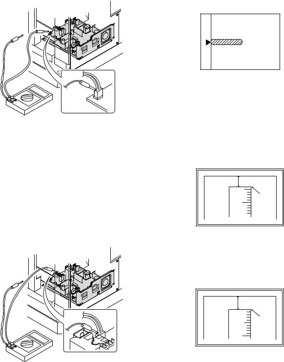
(3)Developing bias voltage check
Note:Use a digital multi-meter with an internal resistance of 10MΩ or more.
1)Set the digital multi-meter range to DC700V.
2)Put the test rod of the digital multi-meter on the developing bias voltage output check pin.
3)Turn on the power, execute SIM25-1.
<Specification>
|
Mode |
Specification |
|
Developing bias voltage |
DC — 400±10V |
(4) Grid bias voltage check
Note:Use a digital multi-meter with an internal resistance of 10MΩ or more.
1)Set the digital multi-meter range to DC700V.
2)Put the test rod of the digital multi-meter on the grid bias voltage output check pin.
3)Turn on the power.
(The voltage is outputted in the grid bias High output mode during warming up, and in the grid bias Low output mode when warming up is completed.)
B.Mechanism section
Note: If a jam error or paper empty occurs during copying in the adjustment by the simulation, the image data are not saved, and therefore recopying is required.
(1) Image position adjustment
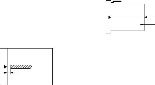
a.OC image lead edge position adjustment (SIM 50-1)
Note:In advance to this adjustment, the sub scanning magnification ratio adjustment must be performed.
1) Set a scale on the OC table as shown below.
2)Make a copy.
3)Check the copy output. If necessary, perform the following adjustment procedures.
4)Execute SIM 50-1.
5)Set the OC lead edge position set value (PHOTO indicator ON) to [1] The OC image scanning start position is shifted inside the document edge.
6)Set the 1st tray lead edge void adjustment value (TEXT indicator ON) * to [1]
The lead edge void becomes the minimum.
7)Set the 1st tray print start position value (AUTO, 1st tray indicator ON) to [1] and make a copy.
The print start position is shifted inside the document edge.
*The dimension varies depending on the model.
 Measure the image loss R of the copied image. Enter the set value of the image scanning lead edge position (PHOTO indicator ON) again.
•1 step of the set value corresponds to about 0.1mm shift. •Calculate the set value from the formula below. R/0.1(mm) = Image loss set value
<R: Image loss measurement value (mm)>
*The scanning edge is set.
(A line may be printed by scanning the document edge.)
<Specification>
|
Mode |
Specification |
|
Grid bias LOW |
DC — 380±8V |
|
Grid bias HIGH |
DC — 525±10V |
Example: 4/0.1 = 40 = about 40
Note:If the set value is not obtained from the above formula, perform the fine adjustment.
AR-5520 ADJUSTMENT 6-2
![]()
9)Measure the distance H between the paper lead edge and the image print start position. Set the image print start position set value
(AUTO, 1st tray indicator ON) again.
•1 step of the set value corresponds to about 0.1mm shift. •Calculate the set value from the formula below. H/0.1(mm) = Image print start position set value
<H: Print start position measurement value (mm)>
*Fit the print edge with the paper edge, and perform the lead edge adjustment.
Example: 5/0.1 = 50 = about 50
Note:If the set value is not obtained from the above formula, perform the fine adjustment.
10) Set the lead edge void adjustment value (TEXT indicator ON)* again. •1 step of the set value corresponds to about 0.1mm shift.
•Calculate the set value from the formula below. B/0.05 (mm) = Lead edge void adjustment value <B: Lead edge void (mm)>
Example: When setting the lead edge void to 2.5mm :2.5 /0.05 = about 50
Note:If the set value is not obtained from the above formula, perform the fine adjustment.
*2nd tray lead edge void adjustment: Exposure display <<AUTO + TEXT + PHOTO>>
Bypass tray lead edge void adjustment: (TEXT indicator and PHOTO indicator ON)
<Duplex mode adjustment>
OC 2nd print surface (Auto duplex) lead edge position adjustment: SIM50-19 <<PHOTO>>
*For the adjustment procedure, set to S → D mode before execution.
Note:Before performing the 2nd print surface lead edge position adjustment and the lead edge void adjustment, be sure to perform the 1st print surface lead edge position adjustment in advance, and be sure to perform the 2nd print surface lead edge position adjustment and then the lead edge void adjustment in this sequence.
<Adjustment specification>
|
Adjustment |
SIM |
LED |
Set |
Spec |
Set |
|
mode |
value |
value |
range |
||
|
OC image lead |
SIM |
PHOTO |
R/0.1 |
Lead edge |
1 ~ 99 |
|
edge position |
50-1 |
||||
|
void: |
|||||
|
1st tray print |
AUTO |
B/0.1 |
|||
|
start position |
+ |
1 — 4mm |
|||
|
1st tray |
Image loss: |
||||
|
2nd tray print |
AUTO |
||||
|
3mm or |
|||||
|
start position |
+ |
||||
|
less |
|||||
|
2nd tray |
|||||
|
Bypass tray |
AUTO |
||||
|
print start |
+ |
||||
|
position |
Bypass |
||||
|
tray |
|||||
|
Lead edge void |
TEXT |
B/0.05 |
|||
|
OC 2nd print |
SIM |
PHOTO |
1 step: |
||
|
surface lead |
50-19* |
0.1mm shift |
|||
|
edge position |
|||||
|
adjustment |
|||||
*(Set to S → D mode for before execution)
b.SPF image lead edge position adjustment (SIM50-6)
1) Set a scale on the OC table as shown below.
Note: Since the printed copy is used as a test chart, put the scale in paralled with the edge lines.
2)Make a copy, Then use the copy output as an original to make an SPF copy again.
3)Check the copy output. If necessary, perform the following adjustment procedures.
4)Execute SIM 50-6.
5)Set the SPF lead edge position set value (AUTO indicator ON) so that the same image is obtained as that obtained in the previous OC image lead edge position adjustment.
<Adjustment specification>
|
Adjustment mode |
SIM |
LED |
Set value |
Spec value |
Set |
|
range |
|||||
|
SPF image lead |
SIM |
AUTO |
1 step: |
Lead edge |
1 ~ 99 |
|
edge position |
50-6 |
0.1mm shift |
void: |
||
|
(1st print surface) |
1 — 4mm |
||||
|
(2nd print surface) |
TEXT |
Image loss: |
|||
|
3mm or |
|||||
|
less |
|||||
AR-5520 ADJUSTMENT 6-3
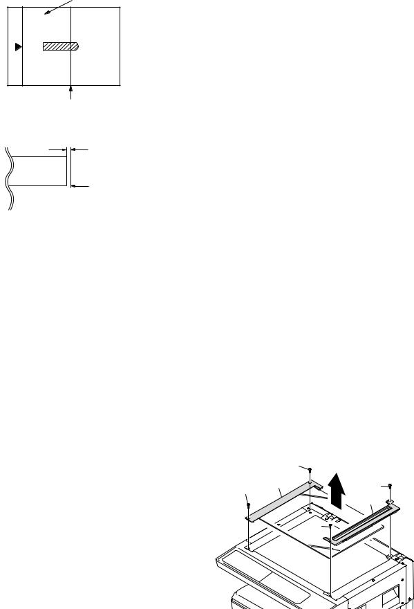
c.Rear edge void adjustment (SIM50-1, SIM50-19)
1) Set a scale as shown in the figure below.
A4(8.5″ x 11″)
Paper rear edge
2)Set the document size to A4 (8.5″ x 11″), and make a copy at 100%.
3)If necessary, perform the following adjustment procedure.
Void amount (Standard value: 4mm or less)
Scale image
Paper rear edge
4)Execute SIM 50-1 and set the density mode to AUTO + TEXT + PHOTO (Rear edge void).The currently set adjustment value is displayed.
5)Enter the set value and press the [START] key. The correction value
is stored and a copy is made.
<Duplex mode adjustment>
*1st print surface (auto duplex) rear edge void adjustment: SIM50-19 <<AUTO>>
*2nd print surface (auto duplex) rear edge void adjustment: SIM50-19<<TEXT>>
*Set to S → D mode before execution.
Note:Before performing the 2nd print surface rear edge void adjustment, be sure to perform the 2nd print surface lead edge position adjustment. Never reverse the sequence.
<Adjustment specification>
|
Mode |
SIM |
LED |
Set value |
Specifi- |
Set |
|
cation |
range |
||||
|
Rear edge void |
SIM |
AUTO |
1 step: |
4mm or |
1 ~ 99 |
|
50-1 |
+ |
0.1mm shift |
less |
||
|
TEXT |
|||||
|
+ |
|||||
|
PHOTO |
|||||
|
1st print |
SIM |
AUTO |
|||
|
surface rear |
50-19* |
||||
|
edge void |
|||||
|
2nd print |
SIM |
TEXT |
|||
|
surface rear |
50-19* |
||||
|
edge void |
|||||
*Set to S → D mode before execution
d. Paper off center adjustment (SIM50-10)
1)Set a test chart (UKOG-0089CSZZ) on the document table.
2)Select a paper feed port and make a copy. Compare the copy and the test chart. If necessary, perform the following adjustment procedure.
3)Execute SIM 50-10. After completion of warm-up, shading is performed and the currently set off center adjustment value of each paper feed port is displayed.
4)Enter the set value and press the [START] key. The correction value is stored and a copy is made.
<Duplex mode adjustment>
*2nd print surface (auto duplex) off-center adjustment: SIM50-10 (TEXT, 1st tray indicator)
<Adjustment specification>
|
Mode |
SIM |
LED |
Set value |
Specifi- |
Set |
|
cation |
range |
||||
|
Paper off |
SIM |
AUTO |
Add 1: |
Single: |
1 ~ 99 |
|
center |
50-10 |
+ |
0.1mm shift |
Center |
|
|
Selected |
to R side. |
±2.0mm |
|||
|
tray ON |
|||||
|
Reduce 1: |
|||||
|
2nd print |
SIM |
TEXT |
Duplex: |
||
|
surface off- |
50-10 |
+ |
0.1mm shift |
Center |
|
|
center |
1st tray |
to L side. |
±2.5mm |
||
e.Side edge void area adjustment (SIM26-43)
Note:Before performing this adjustment, be sure to check that the paper off center adjustment (SIM 50-10) is completed.
1)Set a test chart (UKOG-0089CSZZ) on the document table.
2)Select a paper feed port and make two copies. Compare the 2nd copy and the test chart. If necessary, perform the following
adjustment procedure.
*The 1st copy does not show the void. Be sure to check the 2nd copy.
3)Execute SIM 26-43 and set the density mode to AUTO(right edge void) + TEXT (Left edge void).
The currently set adjustment value is displayed.
4)Enter the set value and press the [START] key. The correction value is stored.
<Adjustment specification>
|
ode |
SIM |
LED |
Set value |
Specifi- |
Set |
|
cation |
range |
||||
|
Left edge void |
SIM |
AUTO |
1 step: |
0 ~ 10mm |
1 ~ 99 |
|
26-43 |
(right |
0.5mm shift |
|||
|
edge) |
|||||
|
+ |
|||||
|
TEXT |
|||||
|
(left edge) |
|||||
*The void adjustment values on the right and the left must be the same.
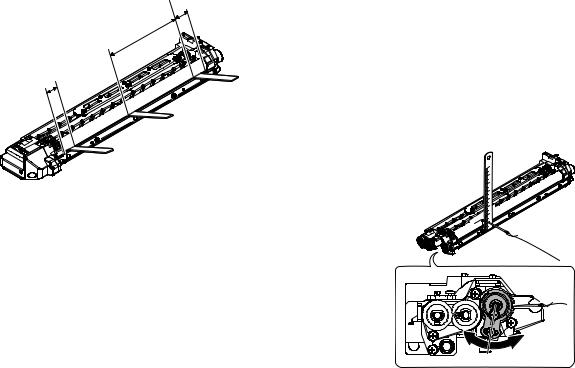
(2)Main scanning direction(FR direction) distortion balance adjustment
1) Remove the OC glass and the right cabinet.
AR-5520 ADJUSTMENT 6-4
2) Loosen the copy lamp unit wire fixing screw.
4)Loosen the set screw of the scanner drive pulley which is not in contact with No. 2/3 mirror base unit positioning plate.
5)Without moving the scanner drive pulley shaft, manually turn the scanner drive pulley until the positioning plate is brought into contact with No. 2/3 mirror base unit, then fix the scanner drive pulley.
Wire fixing screw
3)Manually turn the mirror base drive pulley and bring No. 2/3 mirror base unit into contact with the positioning plate. At that time, if the front frame side and the rear frame side of No. 2/3 mirror base unit are brought into contact with the positioning plate at the same time, the mirror base unit parallelism is proper. If one of them is in contact with the positioning plate, perform the adjustment of 4).
6)Put No. 2/3 mirror base unit on the positioning plate again, push the projections on the front frame side and the rear frame side of the copy lamp unit to the corner frame, and tighten the wire fixing screw.
AR-5520 ADJUSTMENT 6-5

(3)Main scanning direction (FR direction) distortion adjustment
This adjustment must be performed in the following cases:
•When the mirror base drive wire is replaced.
•When the lamp unit, or No. 2/3 mirror holder is replaced.
•When a copy as shown is made.
Paper exit direction
1) Set A3 (11″ x 17″) white paper on the original table as shown below.
Allow a little space.
|
Glass holding plate |
A3 (11″ x 17″) white paper |
Fit the paper edge and
the glass holding plate edge.
2)Open the original cover and make a normal (100%) copy.
3)Measure the width of the black background at the lead edge and at the rear edge.
Paper exit direction
La: Lead edge black background width
Lb: Rear edge black background width
If the width (La) of the black background at the lead edge is equal that (Lb) at the rear edge, there is no need to execute the following procedures of 4) ~ 7).
4)Loosen the mirror base drive pulley fixing screw on the front frame side or on the rear frame side.
 When La < Lb
Turn the mirror base drive pulley on the front frame side in the arrow direction A.
(Do not move the mirror base drive pulley shaft.)
 When La > Lb
Turn the mirror base drive pulley on the front frame side in the arrow direction A.
(Do not move the mirror base drive pulley shaft.)
Rear side
A
B
Front side
5)Tighten the mirror base drive pulley fixing screw.
<Adjustment specification>
La = Lb
6)Execute the main scanning direction (FR) distartion balance adjustment previously described in 2) again.
(4)Sub scanning direction (scanning direction) distortion adjustment
When there is no skew copy in the mirror base scanning direction and there is no horizontal error (right angle to the scanning direction), the adjustment can be made by adjusting the No. 2/3 mirror base unit rail height.
Before performing this adjustment, be sure to perform the horizontal image distortion adjustment in the laser scanner section.
This adjustment must be performed in the following cases:
•When the mirror base wire is replaced.
•When the copy lamp unit or No. 2/3 mirror unit is replaced.
•When the mirror unit rail is replaced or moved.
•When a following copy is made.
AR-5520 ADJUSTMENT 6-6
1)Making of a test sheet
Make test sheet by drawing parallel lines at 10mm from the both ends of A3 (11″ x 17″) white paper as shown below. (These lines must be correctly parallel to each other.)
|
Parallel line |
Parallel line |
|
10mm |
10mm |
White paper
2)Make a normal (100%) copy of the test sheet on A3 (11″ x 17″) paper. (Fit the paper edge with the glass holding plate edge.)
3)Measure the distances (La, Lb, Lc, Ld) at the four corners as shown below.
|
La |
Lc |
|||||
Paper exit direction
When La = Lb and Lc = Ld, no need to perform the procedures 4) and 5).
4)Move the mirror base F rail position up and down (in the arrow direction) to adjust.
Note:Do not adjust the rail on the rear side.
If the rail on the rear side is adjusted, a trouble may be caused. Only the rail on the front side can be adjusted.
 When La > Lb
Shift the mirror base B rail upward by the half of the difference of La — Lb.
 When La < Lb
Shift the mirror base B rail downward by the half of the difference of Lb — La.
Example: When La = 12mm and Lb = 9mm, shift the mirror base B rail upward by 1.5mm.
 When Lc > Ld
Shift the mirror base B rail downward by the half of the difference of Lc — Ld.
 When Lc < Ld
Shift the mirror base B rail downward by the half of the difference of Ld — Lc.
 When moving the mirror base rail, hold the mirror base rail with your hand.
<Adjustment specification>
La = Lb, Lc = Ld
5)After completion of adjustment, manually turn the mirror base drive pulley, scan the mirror base A and mirror base B fully, and check that
the mirror bases are not in contact with each other.
*If the mirror base rail is moved extremely, the mirror base may be in contact with the frame or the original glass. Be careful to avoid this.
(5)Main scanning direction (FR direction) magnification ratio adjustment (SIM 48-1)
Note: Before performing this adjustment, be sure to check that the CCD unit is properly installed.
1) Put a scale on the original table as shown below.
2)Execute SIM 48-1.
3)After warm-up, shading is performed and the current set value of the main scanning direction magnification ratio is displayed on the display section in 2 digits.
4)Select the mode and press the [START] key again.
5)Manual correction mode (TEXT indicator ON) Enter the set value and press the [START] key. The set value is stored and a copy is made.
AR-5520 ADJUSTMENT 6-7
<Adjustment specification>
Note: A judgment must be made with 200mm width, and must not be made with 100mm width.
|
Mode |
Specification |
SIM |
Set value |
Set range |
|
Main scanning |
At normal: |
SIM 48-1 |
Add 1:0.1% |
1 ~ 99 |
|
direction |
±1.0% |
increase |
||
|
magnification |
Reduce 1: |
|||
|
ratio |
0.1% |
|||
|
decrease |
||||
(6)Sub scanning direction (scanning direction) magnification ratio adjustment (SIM 48-1, SIM 48-5)
a. OC mode in copying (SIM48-1)
Note:Before performing this adjustment, be sure to check that the CCD unit is properly installed.
1)Put a scale on the original table as shown below, and make a normal (100%) copy.
2)Compare the scale image and the actual image. If necessary, perform the following adjustment procedures.
3)Execute SIM 48-1.<<PHOTO>>
4)After warm-up, shading is performed and the current set value of the main scanning direction magnification ratio is displayed on the display section in 2 digits.
5)When the photo indicator is lighted by pressing the AUTO/TEXT/ PHOTO key, the current magnification ratio correction value in the sub scanning direction is displayed in lower 2 digits of the display section.
6)Enter the set value and press the [START] key. The set value is stored and a copy is made.
<Adjustment specification>
|
Mode |
Specification |
SIM |
Set value |
Set range |
|
Sub scanning |
Normal |
SIM 48-1 |
Add 1:0.1% |
1 ~ 99 |
|
direction |
±1.0% |
(PHOTO) |
increase |
|
|
magnification |
Reduce 1: |
|||
|
ratio |
0.1% |
|||
|
(OC mode) |
decrease |
|||
b. RSPF sub scanning direction magnification ratio (SIM48-5)
Note:
•Before performing this adjustment, be sure to check that the CCD unit is properly installed.
•Before performing this adjustment, the OC mode adjustment in copying must be completed.
1)Put a scale on the original table as shown below, and make a normal (100%) copy to make a test chart.
Note:Since the printed copy is used as a test chart, put the scale in parallel with the edge lines.
2)Set the test chart on the SPF and make a normal (100%) copy.
3)Compare the scale image and the actual image. If necessary, perform the following adjustment procedures.
4)Execute SIM 48-5.
5)After warm-up, shading is performed.
The AUTO indicator lights up and the current front surface sub scanning direction magnification ratio correction value is displayed in two digits on the display section.
6)Enter the set value and press the [START] key. The set value is stored and a copy is made.
7)Change the mode from the duplex original mode to the simplex original mode.
TEXT indicator lights up and the current back surface sub scanning direction magnification ratio is displayed in two digits on the display section.
Enter the set value and press the [START] key. The set value is stored and a copy is made.
<Adjustment specification>
|
Mode |
Specification |
SIM |
Set value |
Set range |
|
Sub scanning |
Normal |
SIM 48-5 |
Add 1:0.1% |
1 ~ 99 |
|
direction |
±1.0% |
increase |
||
|
magnification |
Reduce 1: |
|||
|
ratio |
0.1% |
|||
|
(SPF mode) |
decrease |
|||
(7) Off center adjustment (SIM 50-12)
a. OC mode (SIM50-12)
1)Make a test chart as shown below and set it so that its center line is fit with the original guide center mark.
*To make a test chart, draw a line on A3 or 11″ x 17″ paper at the center in the paper transport direction.
Original guide
Center
Copy paper
(A3 or 17″ x 11″)
2)Make a normal copy from the bypass tray, and compare the copy and the test chart.
If necessary, perform the following adjustment procedures.
3)Execute SIM 50-12.
4)After warm-up, shading is performed and the current set value of the off center adjustment is displayed on the display section in 2 digits.
5)Enter the set value and press the [START] key. The set value is stored and a copy is made.
<Adjustment specification>
|
Mode |
Specification |
SIM |
Set value |
Set range |
|
Original off |
Single: |
SIM 50-12 |
Add 1: |
1 ~ 99 |
|
center mode |
Center ±2.0mm |
(AUTO |
0.1mm shift |
|
|
(OC mode) |
indicator |
to R side |
||
|
ON) |
Reduce 1: |
|||
|
0.1mm shift |
||||
|
to L side |
||||
AR-5520 ADJUSTMENT 6-8
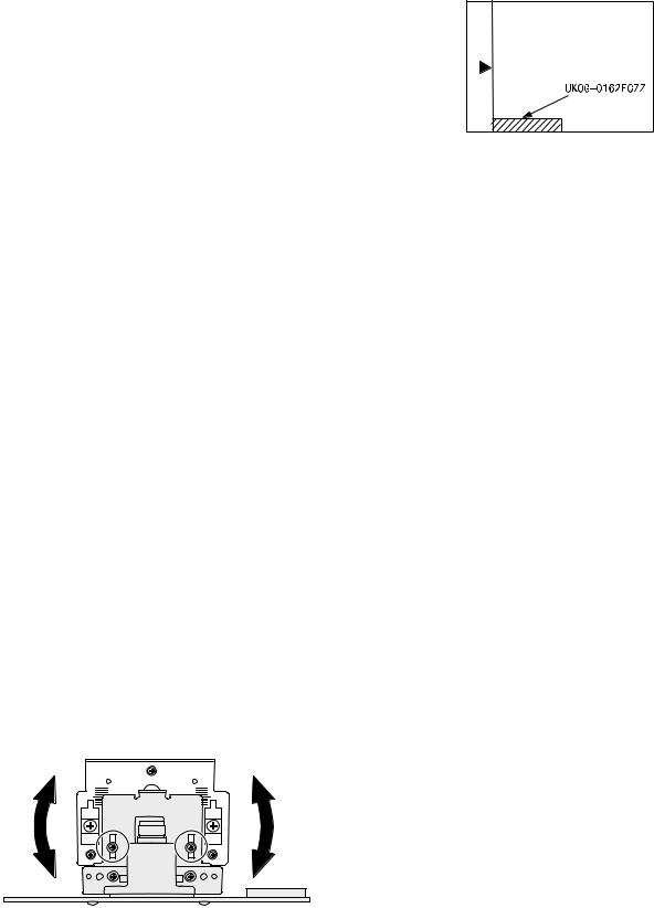
b. SPF original off-center adjustment (SIM50-12)
Note:Before performing this adjustment, be sure to check that the paper off center is properly adjusted.
1) Make a test chart for the center position adjustment and set it on the SPF.
<Adjustment specification>
Draw a line on a paper in the scanning direction.
2)Make a normal copy from the bypass tray, and compare the copy and the original test chart.
If necessary, perform the following adjustment procedures.
3)Execute SIM 50-12.
4)After warm-up, shading is performed and the current set value of the off center adjustment at each paper feed port is displayed on the display section in 2 digits.
5)Enter the set value and press the [START] key. The set value is stored and a copy is made.
<Adjustment specification>
|
Mode |
Specification |
SIM |
Set value |
Set |
|
range |
||||
|
Original off |
Single: |
SIM |
Add 1: |
1 ~ 99 |
|
center |
Center ±3.0mm(TEXT |
50-12 |
0.1mm shift |
|
|
mode |
indicator) |
to R side |
||
|
(SPF mode) |
Reduce 1: |
|||
|
Duplex: |
||||
|
Center ±3.5mm(PHOTO |
0.1mm shift |
|||
|
indicator) |
to L side |
|||
(8) SPF white correction pixel position adjustment(SIM63-7) (required in an SPF model when replacing the lens unit)
1)Fully open the SPF.
2)Execute SIM 63-7.
3)When the operation panel displays «COMPLETE,»the adjustment is completed.
4)If the operation panel displays «ERROR,»perform the following
measures.
•When the display is 0: Check that the SPF is open.
Check that the lamp is ON.(If the lamp is OFF,check the MCU connector.)
Check that the CCD harness is properly inserted into the MCU connector.
•When the display is 281 or above:
1)Remove the table glass.
2)Remove the dark box.
3)Slide the lens unit toward the front side and attach it,then execute SIM.
•When the display is 143 or below:
1)Remove the table glass.
2)Remove the dark box.
3)Slide the lens unit toward the rear side and attach it,then execute SIM.
F R
C.Image density adjustment
(1)Copy mode (SIM 46-1)
1)Set a test chart (UKOG-0162FCZZ) on the OC table as shown below.
2)Put several sheets of A3 or 11″ x 17″ white paper on the test chart.
3)Execute SIM 46-1.
4)After warm-up, shading is performed and the current set value of the density level is displayed on the display section in 2 digits.
For mode selection, use the AUTO/TEXT/PHOTO key.
5)Change the set value with the Numeric keys to adjust the copy image density.
6)Make a copy and check that the specification below is satisfied.
<Adjustment specification>
|
Density |
LED |
Exposure |
Sharp Gray |
Set value |
Set |
|
mode |
level |
Chart output |
range |
||
|
Auto |
Auto |
— |
«2» is slightly |
The greater the |
1 ~ 99 |
|
copied. |
set value is the |
||||
|
greater the |
|||||
|
Text |
Text |
3 |
«3» is slightly |
||
|
copied. |
density is The |
||||
|
smaller the set |
|||||
|
Photo |
Photo |
3 |
«2» is slightly |
||
|
(Error |
copied. |
value is the |
|||
|
smaller the |
|||||
|
diffusion) |
|||||
|
density is. |
|||||
|
Toner |
Text/ |
3 |
«3» is slightly |
||
|
save |
Photo |
copied |
|||
|
Toner |
Auto/ |
— |
«2» is slightly |
||
|
save |
Photo |
copied |
|||
|
Photo |
Auto/ |
3 |
«2» is slightly |
||
|
(Dither) |
Text/ |
copied |
|||
|
Photo |
|||||
*When the lens unit is moved,execute the OC main scanning magnification ratio auto adjustment,SIM 48-1-1,SIM48-3 and the PF original off-center adjustment.
*This adjustment is basically O.K.with SIM 63-7.
AR-5520 ADJUSTMENT 6-9

[7] SIMULATIONS
1. Entering the simulation mode
Perform the following procedure to enter the simulation mode. «#» key  Interrupt key
  CLEAR key (
  )
)  Interrupt key Main code
  [START] key
  Sub code
  [START] key
2. Canceling the simulation mode
When the CLEAR ALL key is pressed, the simulation mode is cancelled. When the INTERRUPT key is pressed, the process is interrupted and the screen returns to the sub code entering display.
*After canceling the simulation mo de, be sure to turn OFF/ON the power and check the operation.
Note: If the machine is terminated by a jam error or paper empty during copying in the adjustment by the simulation, recopying is required.
3. List of simulations
|
Main |
Sub |
Contents |
|
|
code |
code |
||
|
01 |
01 |
Mirror scanning operation |
|
|
02 |
Mirror home position sensor (MHPS) status display |
||
|
06 |
Mirror scanning operation aging |
||
|
02 |
01 |
Single paper feeder (SPF) aging |
|
|
02 |
SPF sensor status display |
||
|
03 |
SPF motor operation check |
||
|
08 |
SPG paper feed solenoid operation check |
||
|
09 |
RSPF reverse solenoid operation check |
||
|
11 |
SPF PS release solenoid operation check |
||
|
05 |
01 |
Operation panel display check |
|
|
02 |
Fusing lamp and cooling fan operation check |
||
|
03 |
Copy lamp lighting check |
||
|
06 |
01 |
Paper feed solenoid operation check |
|
|
02 |
Resist roller solenoid operation check |
||
|
10 |
1st tray semicircular roller cleaning |
||
|
07 |
01 |
Warm-up display and aging with jam |
|
|
06 |
Intermittent aging |
||
|
08 |
Shifting with warm-up display |
||
|
08 |
01 |
Developing bias output |
|
|
02 |
Main charger output (Grid = HIGH) |
||
|
03 |
Main charger output (Grid = LOW) |
||
|
06 |
Transfer charger output |
||
|
09 |
01 |
Duplex motor forward rotation check |
|
|
02 |
Duplex motor reverse rotation check |
||
|
04 |
Duplex motor RPM adjustment |
||
|
05 |
Duplex motor switchback time adjustment |
||
|
10 |
— |
Toner motor operation |
|
|
14 |
— |
Trouble cancel (except for U2) |
|
|
16 |
— |
U2 trouble cancel |
|
|
20 |
01 |
Maintenance counter clear |
|
|
21 |
01 |
Maintenance cycle setting |
|
|
02 |
Mini maintenance cycle setting |
||
|
22 |
01 |
Maintenance counter display |
|
|
02 |
Maintenance preset display |
||
|
03 |
Jam memory display |
||
|
04 |
Jam total counter display |
||
|
05 |
Total counter display |
||
|
06 |
Developing counter display |
||
|
07 |
Mini maintenance preset display |
||
|
08 |
SPF counter display |
||
|
09 |
Paper feed counter display |
||
|
12 |
Drum counter display |
||
|
13 |
CRUM type display |
||
|
14 |
P-ROM version display |
||
|
15 |
Trouble memory display |
||
|
16 |
Duplex print counter display |
||
|
17 |
Copy counter display |
||
|
18 |
Printer counter display |
||
|
19 |
Scanner mode counter display |
||
|
21 |
Scanner counter display |
||
|
22 |
SPF jam counter display |
||
|
50 |
Developer rotation time display |
||
|
51 |
Drum rotation time display |
||
AR-5520 SIMULATIONS 7-1
|
Main |
Sub |
Contents |
|
|
code |
code |
||
|
24 |
01 |
Jam total counter clear |
|
|
02 |
Trouble memory clear |
||
|
04 |
SPF counter clear |
||
|
05 |
Duplex print counter clear |
||
|
06 |
Paper feed counter clear |
||
|
07 |
Drum counter clear |
||
|
08 |
Copy counter clear |
||
|
09 |
Printer counter clear |
||
|
13 |
Scanner counter clear |
||
|
14 |
SPF jam total counter clear |
||
|
15 |
Scanner mode counter clear |
||
|
25 |
01 |
Main motor operation check |
|
|
02 |
Auto developer adjustment (Initial setting of toner |
||
|
density when replacing developer) |
|||
|
10 |
Polygon motor operation check |
||
|
26 |
02 |
Size setting |
|
|
03 |
Auditor setting |
||
|
04 |
Copier duplex setting |
||
|
05 |
Count mode setting |
||
|
06 |
Destination setting |
||
|
07 |
Machine condition check (CPM) |
||
|
18 |
Toner save mode setting |
||
|
30 |
CE mark conformity control ON/OFF |
||
|
31 |
Auditor mode exclusive setup |
||
|
36 |
Cancel of stop at maintenance life over |
||
|
37 |
Cancel of stop at developer life over |
||
|
38 |
Cancel of stop at drum life over |
||
|
39 |
Memory capacity check |
||
|
42 |
Transfer ON/OFF timing control setting |
||
|
43 |
Side void amount setting |
||
|
51 |
Copy temporary stop function setting |
||
|
54 |
Life correction ON/OFF setting |
||
|
69 |
Operation setting when CRUM toner end |
||
|
30 |
01 |
Paper sensor status display |
|
|
42 |
01 |
Developing counter clear |
|
|
43 |
01 |
Fusing temperature setting |
|
|
10 |
Postcard paper feed cycle setting |
||
|
11 |
Postcard size paper fusing temperature setting |
||
|
12 |
Standby mode fusing fan rotation setting |
||
|
13 |
Fusing paper interval control allow/inhibit setting |
||
|
44 |
01 |
Toner density control Enable/Disable (ON/OFF) setting |
|
|
16 |
Toner density control data check and toner density |
||
|
control correction amount display |
|||
|
34 |
Transfer current setting |
||
|
40 |
Setting of rotation time before toner supply |
||
|
Main |
Sub |
Contents |
|
|
code |
code |
||
|
46 |
01 |
Copy density adjustment (300dpi) |
|
|
02 |
Copy density adjustment (600dpi) |
||
|
09 |
Copy exposure level adjustment, individual setting |
||
|
(Text) 300dpi |
|||
|
10 |
Copy exposure level adjustment, individual setting |
||
|
(Text) 600dpi |
|||
|
11 |
Copy exposure level adjustment, individual setting |
||
|
(Photo) 600dpi |
|||
|
18 |
Image contrast adjustment (300dpi) |
||
|
19 |
Exposure mode setting |
||
|
(Gamma table setting/AUTO exposure operation mode |
|||
|
setting/Photo image process setting) |
|||
|
20 |
SPF exposure correction |
||
|
29 |
Image contrast adjustment (600dpi) |
||
|
30 |
AUTO exposure limit setting |
||
|
31 |
Image sharpness adjustment |
||
|
48 |
01 |
Main/sub scanning magnification ratio adjustment |
|
|
05 |
SPF/RSPF mode sub scanning magnification ratio |
||
|
adjustment in copying |
|||
|
49 |
01 |
Flash ROM program writing mode |
|
|
50 |
01 |
Image lead edge adjustment |
|
|
06 |
Copy lead edge position adjustment (SPF/RSPF) |
||
|
10 |
Paper off-center adjustment |
||
|
12 |
Document off-center adjustment |
||
|
18 |
Memory reverse position adjustment in duplex copy |
||
|
19 |
Rear edge void adjustment in duplex copy |
||
|
51 |
02 |
Resist amount adjustment |
|
|
53 |
08 |
SPF scanning position automatic adjustment |
|
|
10 |
SPF document scan position select setting |
||
|
60 |
01 |
SDRAM (image memory area) access check |
|
|
61 |
02 |
Laser power correction ON/OFF |
|
|
03 |
HSYNC output check |
||
|
63 |
01 |
Shading check |
|
|
07 |
SPF automatic correction |
||
|
64 |
01 |
Self print |
|
AR-5520 SIMULATIONS 7-2
Download Service manual of Sharp AR-5516 All in One Printer, Copier for Free or View it Online on All-Guides.com. This version of Sharp AR-5516 Manual compatible with such list of devices, as: AR-5516, AR-5516D, AR-5516S, AR-5520, AR-5520S

1

2

3

4

5

6

7

8

9

10

11

12

13

14

15

16

17

18

19

20

21

22

23

24

25

26

27

28

29

30

31

32

33

34

35

36

37

38

39

40

41

42

43

44

45

46

47

48

49

50

51

52

53

54

55

56

57

58

59

60

61

62

63

64

65

66

67

68

69

70

71

72

73

74

75

76

77

78

79

80

81

82

83

84

85

86

87

88

89

90

91

92

93

94

This document has been published to be used for
after sales service only.
The contents are subject to change without notice.
Parts marked with “ “ are important for maintaining the safety of the set.
Be sure to replace these parts with specified ones for maintaining the safety and performance of the set.
SHARP CORPORATION
DIGITAL COPIER
AR-5520 AR-5516
AR-5520S AR-5516S
AR-5520D AR-5516D
CODE : 00ZAR5520/S1E
AR-5516 AR-5516S
AR-5516D
AR-5520 AR-5520S
AR-5520D
(With RSPF installed)
[ 1 ] GENERAL . . . . . . . . . . . . . . . . . . . . . . . . . . . . . . . . . . . . . . . . . 1 — 1
[ 2 ] CONFIGURATION. . . . . . . . . . . . . . . . . . . . . . . . . . . . . . . . . . . 2 — 1
[ 3 ] SPECIFICATIONS. . . . . . . . . . . . . . . . . . . . . . . . . . . . . . . . . . . 3 — 1
[ 4 ] CONSUMABLE PARTS. . . . . . . . . . . . . . . . . . . . . . . . . . . . . . . 4 — 1
[ 5 ] EXTERNAL VIEWS AND INTERNAL STRUCTURES . . . . . . . 5 — 1
[ 6 ] ADJUSTMENTS . . . . . . . . . . . . . . . . . . . . . . . . . . . . . . . . . . . . 6 — 1
[ 7 ] SIMULATIONS . . . . . . . . . . . . . . . . . . . . . . . . . . . . . . . . . . . . . 7 — 1
[ 8 ] USER PROGRAMS . . . . . . . . . . . . . . . . . . . . . . . . . . . . . . . . . 8 — 1
[ 9 ] TROUBLE CODE LIST . . . . . . . . . . . . . . . . . . . . . . . . . . . . . . . 9 — 1
[10] MAINTENANCE . . . . . . . . . . . . . . . . . . . . . . . . . . . . . . . . . . . 10 — 1
[11] DISASSEMBLY AND ASSEMBLY. . . . . . . . . . . . . . . . . . . . . . 11 — 1
[12] FLASH ROM VERSION UP PROCEDURE . . . . . . . . . . . . . . 12 — 1
[13] ELECTRICAL SECTION . . . . . . . . . . . . . . . . . . . . . . . . . . . . . 13 — 1
CONTENTS
MODEL
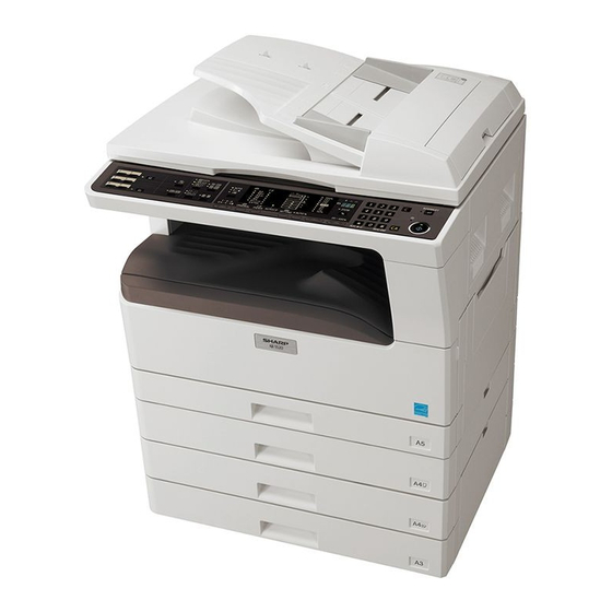
-
Contents
-
Table of Contents
-
Troubleshooting
-
Bookmarks
Quick Links
DIGITAL MULTIFUNCTIONAL SYSTEM
OPERATION GUIDE
MODEL: AR-5516
AR-5520
AR-5516D
AR-5520D
Related Manuals for Sharp AR-5516
Summary of Contents for Sharp AR-5516
-
Page 1: Operation Guide
MODEL: AR-5516 AR-5520 AR-5516D AR-5520D DIGITAL MULTIFUNCTIONAL SYSTEM OPERATION GUIDE…
-
Page 3: Table Of Contents
CONTENTS BEFORE USING THE MACHINE PRINTER FUNCTIONS PART NAMES AND FUNCTIONS ….. 4 BASIC PRINTING ……….35 ● OPERATION PANEL ……..6 ● OPENING THE PRINTER DRIVER FROM THE «Start» BUTTON ……….36 POWER ON AND OFF……..8 ● POWER ON …………8 PRINTER DRIVER SETTING SCREEN ..
-
Page 4
USER SETTINGS PERIPHERAL DEVICES AND SUPPLIES ADJUSTING THE AUTOMATIC EXPOSURE PERIPHERAL DEVICES ……… 85 ● SINGLE PASS FEEDER/REVERSING SINGLE LEVEL ………….. 55 PASS FEEDER ……….86 CUSTOMISING SETTINGS (System Settings)..56 ● 250-SHEET PAPER FEED UNIT/2 X 250- ● SYSTEM SETTINGS ……..56 SHEET PAPER FEED UNIT …… -
Page 5
INTRODUCTION This manual describes the copier, printer, and scanner functions of the AR-5516/AR-5520 and AR-5516D/AR-5520D digital multifunctional system. • Where «AR-XXXX» appears in this manual, please substitute the name of your model for «XXXX». For the name of your model, see «DIFFERENCES BETWEEN MODELS» in the Start Guide. -
Page 6: Before Using The Machine
Chapter 1 BEFORE USING THE MACHINE This chapter contains basic information that should be read before using the machine. PART NAMES AND FUNCTIONS Glass cleaner (when the SPF/RSPF is installed) Paper trays Use to clean the original scanning glass. (p.83) Each tray holds 250 sheets of paper.
-
Page 7
BEFORE USING THE MACHINE Document feeder tray (when the SPF/RSPF is Fusing unit release levers installed) To remove a paper misfeed from the fusing unit, push Place the original(s) that you wish to scan face up down on these levers and remove the paper. (p.76) here. -
Page 8: Operation Panel
BEFORE USING THE MACHINE OPERATION PANEL 6 7 8 9 10 SCAN MENU key SORT/GROUP key ( ) / indicators Use to scan by means of the provided Button Press to select the «SORT» or «GROUP» mode. (p.29) Manager software. (p.48) 2 IN 1 / 4 IN 1 key ( ) / indicators…
-
Page 9
BEFORE USING THE MACHINE 29 30 31 When there are two or more paper trays Display PRESET RATIO selector keys ( indicators Shows the set number of copies, as well as the copy ratio, system setting function or setting code, or an Use to select preset reduction/enlargement copy error code when an error occurs. -
Page 10: Power On And Off
POWER ON AND OFF The power switch is located on the left side of the machine. POWER ON POWER OFF Make sure that the machine is not in Turn the power switch to the «ON» operation and then turn the power switch position.
-
Page 11: Loading Paper
● There are many varieties of special paper available on the market, and some cannot be used with this machine. Before using special paper, contact your authorised service representative. ● Before using other than SHARP recommended paper, make a test copy to see if the paper is suitable.
-
Page 12: Loading Paper
BEFORE USING THE MACHINE LOADING PAPER Make sure that the machine is not copying or printing, and then follow these steps to load paper. Loading the paper tray Gently lift and pull out the paper tray Gently push the paper tray into the until it stops.
-
Page 13: Loading The Bypass Tray
• When loading envelopes, make sure that they are straight and flat and do not have loosely glued construction flaps (not the closure flap). • Special papers except SHARP recommended transparency film, labels, and envelopes must be fed one sheet at a time through the bypass tray.
-
Page 14: Changing A Tray’s Paper Size Setting
BEFORE USING THE MACHINE Envelopes Do not use the following envelopes, as misfeeds will occur. • Envelopes with metal tabs, clasps, strings, holes, or windows. • Envelopes with rough fibres, carbon paper, or glossy surfaces. • Envelopes with two or more flaps. •…
-
Page 15
BEFORE USING THE MACHINE Use the [ORIGINAL] key ( ) to Squeeze the lock lever of the front select the paper size. guide and slide the front guide to match the width of the paper, and The indicator of the move the left guide to the appropriate selected paper size lights slot as marked on the tray. -
Page 16: Operation In Copy, Printer, And Scanner Modes
OPERATION IN COPY, PRINTER, AND SCANNER MODES Some operations cannot be performed simultaneously when the machine is being used in printer mode, copy mode, or scanner mode. Scanning from Scanning from Modes Copying Printing a computer the machine Copy key input Copy During copying Printer…
-
Page 17: Copy Functions
Chapter 2 COPY FUNCTIONS This chapter explains how to use the copy functions. NORMAL COPYING This section explains how to make a regular copy. If «Auditing mode» has been enabled (p.60), enter your 3-digit account number. Copying from the document glass Open the document cover/SPF/RSPF, Press the [ORIGINAL] key ( ) and…
-
Page 18
COPY FUNCTIONS Copying from the SPF/RSPF Make sure that an original has not Press the [START] key ( ) to begin been left on the document glass. copying. Close the SPF/RSPF. The copy is delivered to the paper output tray. Adjust the original guides to the size The default output mode for copying from the… -
Page 19
COPY FUNCTIONS Auto paper select mode (when there are two or more paper trays) When the AUTO PAPER SELECT indicator ( ) lights up, «Auto paper select mode» is enabled. This function AUTO automatically selects the paper that is the same size as the original A5, B5, B5R, A4, A4R, B4, A3 paper. «Auto paper select mode»… -
Page 20: Making A Copy Darker Or Lighter
COPY FUNCTIONS MAKING A COPY DARKER OR LIGHTER Automatic exposure adjustment is initially enabled. This function automatically adjusts the copy image according to the original being copied. If you wish to select the exposure level yourself, follow the steps below. (Select from two original types and five exposure levels for each original type.) The exposure level used in automatic exposure adjustment can also be changed.
-
Page 21: Setting The Number Of Copies
COPY FUNCTIONS SETTING THE NUMBER OF COPIES Press the numeric keys to set the number of copies. Important note when making a large number of copies When the maximum number of pages (about 250 pages) that can be held in the paper output tray are output, copying will temporarily stop.
-
Page 22: Manual Ratio Selection
COPY FUNCTIONS Press the [AUTO IMAGE] key ( Set the number of copies and other AUTO % copy settings, and then press the [START] key ( The AUTO IMAGE indicator ( ) lights The copy will be delivered to the paper output AUTO % up and the appropriate tray.
-
Page 23: Selecting The Vertical And Horizontal Copy Ratios Separately (Xy Zoom Copying)
COPY FUNCTIONS SELECTING THE VERTICAL AND HORIZONTAL COPY RATIOS SEPARATELY (XY ZOOM Copying) The XY ZOOM feature allows the horizontal and vertical copy ratios to be changed independently. Example: Reduction only in the horizontal direction. Original Copy • This feature cannot be used with the 2 IN 1 or 4 IN 1 feature. (p.31) Note •…
-
Page 24
COPY FUNCTIONS Use the [PRESET RATIO] selector keys ( ) and [Zoom] keys ( ) to change the copy ratio in the horizontal direction. Press the [PRESET RATIO] selector keys ( ) to select a ratio close to the desired ratio, and then press the [Zoom] keys ( ) to adjust the ratio in increments of 1%. -
Page 25: Automatic Two-Sided Copying (Ar-5516D/Ar-5520D)
AUTOMATIC TWO-SIDED COPYING (AR-5516D/AR-5520D) Two originals placed on the document glass can be copied onto each side of a single sheet of paper. In addition, an RSPF can be used to copy two originals onto one sheet of paper, or one two-sided original onto two sheets of paper, or one two-sided original onto each side of one sheet of paper.
-
Page 26: Using The Rspf
COPY FUNCTIONS Using the document glass Using the RSPF Place the original that you wish to Place originals in the RSPF. (p.16) copy onto the front side of the paper on the document glass and close the If you place an odd number of originals for one-sided to two-sided copying, the last page will document cover.
-
Page 27: Image Rotation In Duplex Copying
COPY FUNCTIONS IMAGE ROTATION IN DUPLEX COPYING This function is used to invert the top and bottom of the image on the front side of the paper during two-sided copying. Hold down the [ORIGINAL TO COPY] key until the indicator blinks. The currently set setting code blinks in the first digit of the number of…
-
Page 28: Two-Sided Copying Using The Bypass Tray
TWO-SIDED COPYING USING THE BYPASS TRAY To perform manual two-sided copying, follow these steps. Example: Copying originals A and B onto each side of one sheet of paper Copy Original A Original B Copy original A. Turn the copy of original A over, and without changing the position of the edge closest to you, insert it in the bypass tray.
-
Page 29: Dual Page Copying
DUAL PAGE COPYING A dual page original can be automatically separated into two pages during copying. This feature is convenient for making copies of books and other dual page originals on individual sheets of paper. Copy Original • A4 paper is used for dual page copying. Note •…
-
Page 30: Interrupting A Copy Run (Interrupt Copying)
INTERRUPTING A COPY RUN (Interrupt Copying) A copy run can be temporarily interrupted to allow another copy job to be performed. When the other job is finished, the copy run will resume using the original copy settings. Interrupt copying is not possible when sort/group copying, 2 IN 1 / 4 IN 1 copying, or two-sided copying is being Note performed.
-
Page 31: Convenient Copy Functions
CONVENIENT COPY FUNCTIONS This section explains major convenient copy functions. ROTATING THE IMAGE 90 DEGREES (Rotation Copy) When «Auto paper select mode» or «automatic ratio selection» are in operation and the original is placed in a different orientation (vertical or horizontal) than the paper, the original image will be automatically rotated 90 degrees to enable correct copying onto the paper.
-
Page 32: Using The Document Glass
COPY FUNCTIONS Using the document glass Using the SPF/RSPF Place the first original. (p.15) Place the originals. (p.16) Sort mode is normally the default output mode, Select the original size. (p.15) and thus the SPF/RSPF and SORT indicators light up. •…
-
Page 33: Copying Multiple Originals Onto A Single Sheet Of Paper
COPY FUNCTIONS COPYING MULTIPLE ORIGINALS ONTO A SINGLE SHEET OF PAPER (2 IN 1 / 4 IN 1 Copy) Multiple originals can be copied onto a single sheet of paper in a selected layout pattern. This function is convenient for compiling multi-page reference materials into a compact format, or for providing an overview of all pages of a document on a single page.
-
Page 34: Setting The Layout Pattern
COPY FUNCTIONS Using the SPF/RSPF Place the originals. (p.16) • To cancel 2 IN 1 / 4 IN 1 copying, press the Note [CLEAR] key • To cancel 2 IN 1 / 4 IN 1 copy mode, press Press the [2 IN 1 / 4 IN 1] key the [2 IN 1 / 4 IN 1] key ( repeatedly until the 2 IN 1 / 4 IN 1 indicators ) to select the mode.
-
Page 35: Creating Margins When Copying (Margin Shift)
COPY FUNCTIONS CREATING MARGINS WHEN COPYING (Margin Shift) The MARGIN SHIFT feature, in its initial setting, automatically shifts the text or image to increase the margin by approximately 10mm. The location of the margin to be increased can be selected to be either at the left edge or the top of the page (AR-5516D/5520D only).
-
Page 36: Erasing Shadows Around The Edges Of Acopy
COPY FUNCTIONS ERASING SHADOWS AROUND THE EDGES OF A COPY (Erase Copy) ● This feature is used to erase shadows that appear around the edges of copies of books and other thick originals. (EDGE ERASE) ● The feature can also erase the shadow that appears down the centre of books and other originals that open up. (CENTRE ERASE) ●…
-
Page 37: Printer Functions
Before printing, make sure that the correct size of paper for your document has been loaded in the machine. Make sure that the ON LINE indicator Make sure that «SHARP AR-XXXX» is on the operation panel is lit. selected as the printer.
-
Page 38: Opening The Printer Driver From The «Start» Button
Click the «Start» button and select Click the «SHARP AR-XXXX» printer «Control Panel» and then select driver icon.
-
Page 39: Printer Driver Setting Screen
PRINTER DRIVER SETTING SCREEN Some restrictions exist on the combinations of settings that can be selected in the printer driver setup screen. When a restriction is in effect, an information icon ( ) will appear next to the setting. Click the icon to view an explanation of the restriction.
-
Page 40: Setting Advanced Print Functions
SETTING ADVANCED PRINT FUNCTIONS This section explains major advanced print functions. The explanations assume that the paper size and other basic settings have already been selected. For the basic procedure for printing and the steps for opening the printer driver, see «BASIC PRINTING»…
-
Page 41: Fitting The Printed Image To The Paper (Fit To Paper Size)
PRINTER FUNCTIONS FITTING THE PRINTED IMAGE TO THE PAPER (Fit To Paper Size) The printer driver can adjust the size of the printed image to match the size of the paper loaded in the machine. Follow the steps shown below to use this function. The explanation below assumes that you intend to print an A3 size document on A4 size paper.
-
Page 42: Enlarging/Reducing The Print Image (Zoom)
PRINTER FUNCTIONS ENLARGING/REDUCING THE PRINT IMAGE (Zoom) This function is used to enlarge or reduce the image to a selected percentage. This allows you to enlarge a small image or add margins to the paper by slightly reducing an image. Note The «Zoom»…
-
Page 43: Adjusting The Brightness And Contrast Of The Image (Image Adjustment)
PRINTER FUNCTIONS ADJUSTING THE BRIGHTNESS AND CONTRAST OF THE IMAGE (Image Adjustment) The brightness and contrast can be adjusted in the print settings when printing a photo or other image. These settings can be used for simple corrections when you do not have image editing software installed on your computer.
-
Page 44: Two-Sided Printing (Ar-5516D/Ar-5520D)
PRINTER FUNCTIONS TWO-SIDED PRINTING (AR-5516D/AR-5520D) The machine can print on both sides of the paper. This function is useful for many purposes, and is particularly convenient when you want to create a simple pamphlet. Two-sided printing also helps conserve paper. Note When using two-sided printing, select a source other than «Bypass Tray»…
-
Page 45: Saving Frequently Used Print Settings
SAVING FREQUENTLY USED PRINT SETTINGS Settings configured on each of the tabs at the time of printing can be saved as user settings. Saving frequently used settings or complex colour settings under an assigned name makes it easy to select those settings the next time you need to use them.
-
Page 46: Outline Of The Print Status Window
OUTLINE OF THE PRINT STATUS WINDOW When printing begins, the Print Status Window automatically opens. The Print Status Window is a utility that monitors the machine and shows the name of the document being printed and any error messages that occur. Status window Provides information on the current status of the Click a tab to bring it to the front.
-
Page 47: Scanner Functions
Chapter 4 SCANNER FUNCTIONS This chapter explains how to use the scanner functions. • Scan jobs received while the machine is copying or printing will be stored in memory. When the copy job is Note finished, the scan jobs will begin. •…
-
Page 48: Scanning Using The Keys On The Machine
SCANNING USING THE KEYS ON THE MACHINE When scanning is performed by this method, the application that has been set in Button Manager will automatically start and the scanned image will be pasted into the application. For the steps to allocate applications using the Button Manager or other settings, see «BUTTON MANAGER SETTINGS»…
-
Page 49: Outline Of Button Manager
SCANNER FUNCTIONS OUTLINE OF BUTTON MANAGER Button Manager is a software utility that allows you to use the scanner function at the machine. Button Manager allows you to configure six sets of scanning settings as a scan menu on the machine. To view Help for a setting, click the button in the upper right-hand corner of the window and then click the setting.
-
Page 50: Button Manager Settings
If the Button Manager icon does not appear Note on the task bar, click the «Start» button, select «All Programs» («Programs» in Windows 2000), select «Sharp Button Manager U», and then click «Button Manager» to start Button Manager. Click the tab of the scan menu that you want to set up.
-
Page 51: Scanning From Your Computer
Windows Help. SCANNING FROM A TWAIN-COMPLIANT APPLICATION The SHARP scanner driver is compatible with the TWAIN standard, allowing it to be used with a variety of TWAIN-compliant applications. Place the original(s) that you wish to In the «Scanning Source»…
-
Page 52
SCANNER FUNCTIONS Specify the scanning area and set the scan preferences. For information on specifying the scan area and setting the scan preferences, see scanner driver Help. «Scanner driver settings» (p.51) Scanning a large area at high resolution results in a large quantity of data and a Caution prolonged scanning time. -
Page 53: Scanner Driver Settings
SCANNER FUNCTIONS Scanner driver settings The scanner driver setup screen consists of the «Set-up screen», which lets you select scan settings, and the «Preview screen», which shows the scanned image. For details on the scan settings, click the «Help» button in the preview screen to display Help.
-
Page 54
SCANNER FUNCTIONS Preview screen Preview screen «Auto Scan Area Judgement» button Click the «Preview» button in the Set-up screen to Click when the preview screen is displayed to display the scanned image. You can specify the automatically set the scanning area to the entire scanning area by dragging the mouse inside the preview image. -
Page 55: Scanning From A Wia-Compliant Application (Windows Xp/Vista)
• In Windows XP, you can view Help for a installed in your computer, the «Select Device» setting. Click the button in the upper screen will open. Select «SHARP AR-XXXX» right-hand corner of the window and then and click the «OK» button. click the setting.
-
Page 56: Scanning From The «Scanner And Camera Wizard» (Windows Xp)
To begin Hardware», and then click «Scanners scanning, click the «Next» and Cameras». button. Click the «SHARP AR-XXXX» icon and then click «Get pictures» in «Imaging Tasks». The «Scanner and When scanning ends, the following Camera Wizard» will screen will appear.
-
Page 57: User Settings
Chapter 5 USER SETTINGS This chapter explains how to set the automatic exposure level and the system settings, which are custom settings that control fine points of the machine’s operation. ADJUSTING THE AUTOMATIC EXPOSURE LEVEL The exposure level used in automatic exposure adjustment, which automatically adjusts the copy exposure according to the original, can be adjusted.
-
Page 58: Customising Settings (System Settings)
CUSTOMISING SETTINGS (System Settings) The system settings allow you to customise the machine to match your needs. SYSTEM SETTINGS Setting codes Program Program name (factory default setting Explanation number appears in bold) 1: OFF • «Auto clear time» automatically returns the 2: 10 sec.
-
Page 59
USER SETTINGS Setting codes Program Program name (factory default setting Explanation number appears in bold) • When the auto paper select function is enabled and there is no paper that is the same size as the original and loaded in the same orientation, this function will automatically select paper of the same size that is loaded in the opposite orientation, and rotate the image… -
Page 60
SPF/RSPF. 3: Group When the SPF/RSPF is installed. AR-5516/AR-5516D is as follows: 1: Upper tray (factory default), 2: 250-sheet paper feed unit/Upper paper tray of 2 x 250-sheet paper feed unit, 3: Lower paper tray of 2 x 250-sheet paper feed unit,… -
Page 61: Setting
USER SETTINGS SELECTING A SETTING FOR A SYSTEM SETTING Hold down the [Light] key ( ) until Enter the desired setting code by the alarm indicators ( , pressing a numeric key. ) blink. • For the setting codes, «SYSTEM The display shows «- -«…
-
Page 62: Settings For Auditing Mode
SETTINGS FOR AUDITING MODE AUDITING MODE When «Auditing mode» is enabled, a count is kept of the number of copies made by each account (up to 20 accounts can be established), and the counts can be displayed and totalled as necessary. In «Auditing mode», the display shows «- — -«, and this indicates that a 3-digit account number must be entered in order to use the machine for copying.
-
Page 63: Selecting Auditing Mode Settings
USER SETTINGS SELECTING AUDITING MODE SETTINGS Hold down the [Light] key ( ) until Press the [Light] key ( ) to complete the alarm indicators ( , the settings. ) blink. The alarm indicators ( , ) go off and the display returns to the number of The display shows «- -«…
-
Page 64
USER SETTINGS Auditing mode Account number deletion (program No.10) (program No.13) 1 Press the [1] key to enable «Auditing Use this procedure to delete account numbers. A mode» or the [0] key to disable it, and then single account number can be deleted, or all account press the [START] key ( numbers at once. -
Page 65: Resetting Account
USER SETTINGS Resetting account Copying when «Auditing mode» is enabled (program No.15) The copy count of a single account or all accounts can When «Auditing mode» is enabled, «- — -» appears in the be reset to 0. If no account numbers have been display.
-
Page 66: Troubleshooting
Chapter 6 TROUBLESHOOTING This chapter describes troubleshooting and misfeed removal. TROUBLESHOOTING If you experience difficulty using the machine, check the following troubleshooting guide before calling for service. Many problems can be easily resolved by the user. If you are unable to solve the problem using the troubleshooting guide, turn off the power switch and unplug the machine, and contact your authorised service representative.
-
Page 67: Machine/Copying Problems
TROUBLESHOOTING MACHINE/COPYING PROBLEMS The following problems are related to the general operation of the machine and copying. Problem Cause and solution Page The machine is not plugged into a power outlet. – → Plug the machine into a grounded outlet. Power switch OFF.
-
Page 68: Paper Misfeed
TROUBLESHOOTING Problem Cause and solution Page Misfeed occurs. → To remove the misfeed, see «MISFEED REMOVAL». The paper is outside of the specified size and weight range. → Use copy paper within the specified range. Paper curled or damp. → Do not use curled or crimped paper. Replace with dry copy paper. –…
-
Page 69: Copies Are Smudged Or Dirty
TROUBLESHOOTING Problem Cause and solution Page The document glass or the underside of the document cover/SPF/RSPF is dirty. → Clean regularly. Copies are smudged or dirty. Original smudged or blotchy. – → Use a clean original. The scanner glass for the SPF/RSPF is dirty. →…
-
Page 70: Printing And Scanning Problems
In Windows 2000, click the «Start» button, select «Settings» and then click «Printers». 2 If the «SHARP AR-XXXX» printer driver icon is shown but you still cannot print, the printer driver may not have been installed correctly. In this case, delete the software and then reinstall it.
-
Page 71: A Notice Page (Np-001) Has Been Printed, But The Print Data Has Not Been Printed Completely
TROUBLESHOOTING Problem Cause and solution Page A print job containing more data than can be held in the print memory is sent to the machine. A Notice Page (NP-001) has been → Disable the ROPM function on the «Configuration» tab of the printed, but the print data has not printer driver setup screen.
-
Page 72: Poor Scanning Quality
TROUBLESHOOTING Problem Cause and solution Page The document glass or the underside of the document cover/SPF/RSPF is dirty. → Clean regularly. Original smudged or blotchy. – → Use a clean original. You have not specified a suitable resolution. → Make sure that the resolution setting in the scanner driver is –…
-
Page 73: Unable To Scan The Image
TROUBLESHOOTING Problem Cause and solution Page If scanning is not possible, shut down your computer, turn off the machine’s power switch, and unplug the machine’s power cord. Next, start your computer, restore – power to the machine, and try scanning again. If scanning is still not possible, check the following items.
-
Page 74: Indicators And Display Messages
Paper required indicator Developer replacement Misfeed indicator required indicator Display Indication Cause and solution Page Maintenance Steadily Service by an authorised SHARP service technician is – indicator required. Developer Steadily Developer is required. Contact your authorised service replacement – representative.
-
Page 75: Misfeed Removal
MISFEED REMOVAL When a misfeed occurs, the misfeed indicator ( ) and a misfeed location indicator ( ) will blink and the machine will automatically stop. Check the blinking misfeed location indicator to identify the location of the misfeed and remove it. The paper may tear when you remove a misfeed.
-
Page 76: Misfeed In The Bypass Tray
TROUBLESHOOTING Return the originals indicated by the Section C Remove the misfed original from the exit area. minus number in the display to the document feeder tray and press the [START] key ( Copying will resume from the originals that still remained when the misfeed occurred.
-
Page 77: Misfeed In The Machine
TROUBLESHOOTING MISFEED IN THE MACHINE Open the bypass tray and the side Check the misfeed location. Remove cover. the misfed paper following the instructions for each location in the illustration below. If paper is misfed here, go to «B. Misfeed in the fusing area».
-
Page 78
TROUBLESHOOTING B. Misfeed in the fusing area Push gently on both ends of the front Lift the fusing unit release levers, to cover and open it. return them to their operating positions. Turn the roller rotating knob in the direction of the arrow. Close the front cover and side cover. -
Page 79
TROUBLESHOOTING C. Misfeed in the transport area Open the fusing paper guide by pressing down the green-labeled projection on the guide and remove the misfed paper. Be careful not to tear the misfed paper during removal. The fusing unit is hot. Do not touch Warning the fusing unit when removing misfed paper. -
Page 80: Misfeed In The Upper Paper Tray
TROUBLESHOOTING MISFEED IN THE UPPER PAPER TRAY Note Make sure that there is no misfed paper in the tray before pulling it out. (p.75) Lift and pull out the upper paper tray and remove the misfed paper. Be careful not to tear the misfed paper during removal.
-
Page 81: Misfeed In The Lower Paper Tray
TROUBLESHOOTING MISFEED IN THE LOWER PAPER TRAY • Make sure that there is no misfed paper in the tray before pulling it out. (p.75) Note • Use the following procedure to remove misfeeds that occur in the 250-sheet paper feed unit/2 x 250-sheet paper feed unit.
-
Page 82: Replacing The Toner Cartridge
REPLACING THE TONER CARTRIDGE When the toner cartridge replacement required indicator ( ) lights up, the toner cartridge will need replacement soon. Obtain a new cartridge. When the toner cartridge replacement required indicator ( ) blinks, the toner cartridge must be replaced before copying can be resumed. Replace the toner cartridge by following the procedure below.
-
Page 83: Routine Maintenance
Chapter 7 ROUTINE MAINTENANCE This chapter explains how to keep the machine operating smoothly, including viewing copy count, and scan count, the toner level indicator, and cleaning the machine. CHECKING THE TOTAL OUTPUT COUNT AND TONER LEVEL CHECKING THE TOTAL OUTPUT COUNT When «Auditing mode»…
-
Page 84: Checking The Toner Level
ROUTINE MAINTENANCE CHECKING THE TONER LEVEL The toner level is indicated by a 6-level display. Use it as a guideline for replacing the toner cartridge. Hold down the [Light] key ( ) until Hold down the [Copy ratio display] key the alarm indicators ( , ) for more than 5 seconds.
-
Page 85: Routine Maintenance
ROUTINE MAINTENANCE CLEANING THE DOCUMENT GLASS AND SPF/RSPF/DOCUMENT COVER If the document glass, underside of the document cover/SPF/RSPF, or the scanner for originals coming from the SPF/RSPF (the long narrow glass surface on the right side of the document glass) become dirty, the dirt may appear on copies.
-
Page 86: Cleaning The Bypass Tray Paper Feed Roller
ROUTINE MAINTENANCE CLEANING THE BYPASS TRAY PAPER FEED ROLLER If misfeeds occur frequently when feeding envelopes, thick paper, etc. through the bypass tray, wipe the paper feed roller at the feed slot of the bypass tray with a soft, clean cloth dampened with alcohol or water. Paper feed roller CLEANING THE TRANSFER CHARGER If copies start becoming streaky or blotchy, the transfer charger may be dirty.
-
Page 87: Peripheral Devices
PERIPHERAL DEVICES As a part of our policy of continuous improvement, SHARP reserves the right to make design and specification Note changes for product improvement without prior notice. The performance specification figures indicated are nominal values of production units.
-
Page 88: Single Pass Feeder/Reversing Single Pass Feeder
PERIPHERAL DEVICES AND SUPPLIES SINGLE PASS FEEDER/REVERSING SINGLE PASS FEEDER For the names of the parts of the SPF/RSPF, see «PART NAMES AND FUNCTIONS» (p.4). Specifications AR-RP10 (Reversing single pass AR-SP10 (Single pass feeder) feeder) 56 g/m to 90 g/m Weight Acceptable Size…
-
Page 89: Storage Of Supplies
STORAGE OF SUPPLIES Standard supplies for this product that are to be replaced by the user are paper and toner cartridge. For best copying results, be sure to use only SHARP products. Only genuine SHARP consumables carry the Genuine Supplies label.
-
Page 90
OPERATION GUIDE AR5520D-GB3…
-
7/25/2019 Sharp AR 5516-5520 Service Manual
1/94
This document has been published to be used fo
after sales service only.The contents are subject to change
without noticeParts marked with are important for maintaining the safety of
the set.Be sure to replace these par ts with specified ones for
maintaining the safety and performance of the set.SHARP CORPORATION
DIGITAL COPIERAR-5520 AR-5516AR-5520S AR-5516SAR-5520D
AR-5516DCODE : 00ZAR5520/S1E
AR-5516 AR-5516SAR-5516D
AR-5520 AR-5520SAR-5520D
(With RSPF installed)
[ 1 ] GENERAL . . . . . . . . . . . . . . . . . . . . . . . . .
. . . . . . . . . . . . . . . . 1 — 1[ 2 ] CONFIGURATION. . . . . . . . . . . . . . . . . . . . . . .
. . . . . . . . . . . . 2 — 1[ 3 ] SPECIFICATIONS. . . . . . . . . . . . . . . . . . . . . .
. . . . . . . . . . . . . 3 — 1[ 4 ] CONSUMABLE PARTS. . . . . . . . . . . . . . . . . . . . .
. . . . . . . . . . 4 — 1[ 5 ] EXTERNAL VIEWS AND INTERNAL STRUCTURES . . . . . . . 5 —
1[ 6 ] ADJUSTMENTS . . . . . . . . . . . . . . . . . . . . . . .
. . . . . . . . . . . . . 6 — 1[ 7 ] SIMULATIONS . . . . . . . . . . . . . . . . . . . . . . .
. . . . . . . . . . . . . . 7 — 1[ 8 ] USER PROGRAMS . . . . . . . . . . . . . . . . . . . . . .
. . . . . . . . . . . 8 — 1[ 9 ] TROUBLE CODE LIST . . . . . . . . . . . . . . . . . . . .
. . . . . . . . . . . 9 — 1[10] MAINTENANCE . . . . . . . . . . . . . . . . . . . . . . . .
. . . . . . . . . . . 10 — 1[11] DISASSEMBLY AND ASSEMBLY . . . . . . . . . . . . . . . . .
. . . . . 11 — 1[12] FLASH ROM VERSION UP PROCEDURE . . . . . . . . . . . . . .
12 — 1[13] ELECTRICAL SECTION . . . . . . . . . . . . . . . . . . . .
. . . . . . . . . 13 — 1CONTENTS
MODEL
-
7/25/2019 Sharp AR 5516-5520 Service Manual
2/94
-
7/25/2019 Sharp AR 5516-5520 Service Manual
3/94
CONTENTS
[1] GENERAL
1.Note for servicing . . . . . . . . . . . . . . . . . . . . . .
. . . . . . . . . 1-1[2] CONFIGURATION
1.System Configurations . . . . . . . . . . . . . . . . . . . .
. . . . . . . 2-1[3] SPECIFICATIONS
1.Copy mode . . . . . . . . . . . . . . . . . . . . . . . . . .
. . . . . . . . . . 3-1[4] CONSUMABLE PARTS
1.Supply system table . . . . . . . . . . . . . . . . . . . . .
. . . . . . . . 4-12.Environmental conditions . . . . . . . . . . . . . . . . . . .
. . . . . . 4-33. Production number identification . . . . . . . . . . . . . .
. . . . . 4-3[5] EXTERNAL VIEWS AND INTERNAL STRUCTURES
1.Appearance. . . . . . . . . . . . . . . . . . . . . . . . . .
. . . . . . . . . . 5-12.Internal . . . . . . . . . . . . . . . . . . . . . . . . . . .
. . . . . . . . . . . . 5-13.Operation Section . . . . . . . . . . . . . . . . . . . . . .
. . . . . . . . 5-24.Motor, solenoid, clutch . . . . . . . . . . . . . . . . . . .
. . . . . . . . 5-35.Sensor, switch. . . . . . . . . . . . . . . . . . . . . . . .
. . . . . . . . . . 5-46.PWB unit . . . . . . . . . . . . . . . . . . . . . . . . . . .
. . . . . . . . . . . 5-57.Cross sectional view . . . . . . . . . . . . . . . . . . . . .
. . . . . . . . 5-6[6] ADJUSTMENTS
1.Adjustment item list . . . . . . . . . . . . . . . . . . . . .
. . . . . . . . . 6-12.Copier adjustment . . . . . . . . . . . . . . . . . . . . . .
. . . . . . . . . 6-1[7] SIMULATIONS
1.Entering the simulation mode . . . . . . . . . . . . . . . . .
. . . . . 7-12.Canceling the simulation mode. . . . . . . . . . . . . . . . .
. . . . 7-13.List of simulations . . . . . . . . . . . . . . . . . . . . .
. . . . . . . . . . 7-14.Contents of simulations. . . . . . . . . . . . . . . . . . . .
. . . . . . . 7-3[8] USER PROGRAMS
1.List of user programs . . . . . . . . . . . . . . . . . . . .
. . . . . . . . 8-12.Setting the user programs . . . . . . . . . . . . . . . . . .
. . . . . . 8-43.Toner cartridge life . . . . . . . . . . . . . . . . . . . . .
. . . . . . . . . 8-4[9] TROUBLE CODE LIST
1.Trouble code list . . . . . . . . . . . . . . . . . . . . . .
. . . . . . . . . . 9-12.Details of trouble codes . . . . . . . . . . . . . . . . . . .
. . . . . . . 9-1[10] MAINTENANCE
1.Maintenance table . . . . . . . . . . . . . . . . . . . . . .
. . . . . . . . 10-12.Maintenance display system . . . . . . . . . . . . . . . . . .
. . . . 10-23.Note for replacement of consumable parts . . . . . . . . . . .
10-2[11] DISASSEMBLY AND ASSEMBLY
1.High voltage section/Duplex transport section. . . . . . . . .
11-12.Optical section . . . . . . . . . . . . . . . . . . . . . . .
. . . . . . . . . . 11-23.Fusing section . . . . . . . . . . . . . . . . . . . . . . . .
. . . . . . . . . 11-44.Paper exit section . . . . . . . . . . . . . . . . . . . . . .
. . . . . . . 11-65.MCU. . . . . . . . . . . . . . . . . . . . . . . . . . . . . .
. . . . . . . . . . . 11-86.Optical frame unit. . . . . . . . . . . . . . . . . . . . . .
. . . . . . . . . 11-87.LSU . . . . . . . . . . . . . . . . . . . . . . . . . . . . .
. . . . . . . . . . . . 11-98.Tray paper feed section/Paper transport section . . . . . .
11-99.Bypass tray section . . . . . . . . . . . . . . . . . . . . .
. . . . . . . 11-1110.Power section . . . . . . . . . . . . . . . . . . . . . . . .
. . . . . . . 11-1311.Developing section . . . . . . . . . . . . . . . . . . . . .
. . . . . . 11-1412.Process section . . . . . . . . . . . . . . . . . . . . . . .
. . . . . . . 11-1513.Others . . . . . . . . . . . . . . . . . . . . . . . . . . .
. . . . . . . . . . 11-15[12] FLASH ROM VERSION UP PROCEDURE
1.Preparation . . . . . . . . . . . . . . . . . . . . . . . . .
. . . . . . . . . . 12-12.Download procedure . . . . . . . . . . . . . . . . . . . . . .
. . . . . . 12-13.Installation procedure . . . . . . . . . . . . . . . . . . . .
. . . . . . . 12-2[13] ELECTRICAL SECTION
1.Block diagram . . . . . . . . . . . . . . . . . . . . . . . .
. . . . . . . . . 13-12.Actual wiring diagram . . . . . . . . . . . . . . . . . . . .
. . . . . . . 13-2 -
7/25/2019 Sharp AR 5516-5520 Service Manual
4/94AR-5520 GENERAL 1-1
[1] GENERAL
1. Note for servicing
Pictogram
The label ( ) in the fusing area of the machine indicates
thefollowing:: Caution, risk of danger: Caution, hot surface
A. Warningfor servicingThe fusing area is hot. Exercise care in
this area when removing misfedpaper.Do not look directly at the light source. Doing so may damage
your eyes.B. Cautions for servicing
Do not switch the machine rapidly on and off. After turning the
machineoff, wait 10 to 15 seconds before turning it back on.Machine power must be turned off before installing any
supplies.Place the machine on a f irm, level surface.Do not install
the machine in a humid or dusty location.When the machine is not
used for a long time, for example, duringprolonged holidays, turn
the power switch off and remove the powercord from the outlet.When moving the machine, be sure to turn
the power switch off andremove the power cord from the outlet.Do not cover the machine with a dust cover, cloth or plastic
film while thepower is on. Doing so may prevent heat dissipation,
damaging themachine.Use of controls or adjustments or performance of procedures
other thanthose specified herein may result in hazardous laser
radiationexposure.The socket-outlet shall be installed near the machine and shall
be easilyaccessible.C. Note for installation place
Improper installation may damage the machine. Please note
thefollowing during initial installation and whenever the machine
is moved.Caution : If the machine is moved from a cool place to a warm
place,condensation may form inside the machine. Operation in
thiscondition will cause poor copy quality and malfunctions.
Leavethe machine at room temperature for at least 2 hours
beforeuse.Do not install your machine in areas that are:
damp, humid, or very dusty
poorly ventilated
exposed to direct sunlight
subject to extreme temperature or humidity changes, e.g., near
an airconditioner or heater.The machine should be installed near an accessible power outlet
foreasy connection and disconnection.Be sure to connect the power
cord only to a power outlet that meets thespecified voltage and
current requirements. Also make certain the outletis properly
grounded.Note :Connect the machine to a power outlet which is not used
for otherelectric appliances. If a lighting fixture is connected to
the sameoutlet, the light may flicker.Be sure to allow the required space around the machine for
servicingand proper ventilation.20 cm(8″)
20 cm(8″)
20 cm (8″)
-
7/25/2019 Sharp AR 5516-5520 Service Manual
5/94AR-5520 CONFIGURATION 2-1
[2] CONFIGURATION
1. System Configurations
O:Option installation enable X:Option installation disable
Model Option
AR-5520 / AR-5520SAR-5516 /AR-5516S
AR-5520DAR-5516D
Remark
AR-RP10 Duplex document auto feeder (RSPF)X O
AR-SP10 Document auto feeder (SPF) O X
AR-D34 1-stage paper feed unit O O
AR-D35 2-stage paper feed unit O O
AR-D34 AR-D35
AR-SP10
AR-RP10
AR-5520/AR-5520S AR-5516/AR-5516S
AR-5520D AR-5516D
-
7/25/2019 Sharp AR 5516-5520 Service Manual
6/94AR-5520 SPECIFICATIONS 3-1
[3] SPECIFICATIONS
1. Copy mode
A. Type
B. Machine composition
(1) Option
C. Copy speed
(1) Engine speed (ppm)
(2) Document replacement speed (Copy mode)
S to S : Tray1 A4/8.5X11 document 11 sheets (11 pages), copy 1
setS to D : Tray1 A4/8.5X11 document 22 sheets (22 pages), copy 1
setD to D : Tray1 A4/8.5X11 document 11 sheets (22 pages), copy 1
set(3) Job efficiency
S to S : Tray1 A4/8.5X11 document 10 sheets (10 pages), copy 5
setsS to D : Tray1 A4/8.5X11 document 10 sheets (10 pages), copy 5
setsD to D : Tray1 A4/8.5X11 document 10 sheets (20 pages), copy 5
sets(4) First copy time
600x300dpi, AE mode, A4/Letter, single surface copy with OC, in
polygonready stateD. Document
E. Paper feed
(1) Paper feed section details
(2) Feedable paper
Type Desk-top
Paper exit Wing less
AR-5516 / AR-5516S / AR-5516D 16-CPM multi function model
AR-5520 / AR-5520S / AR-5520D 20-CPM multi function model
Machine Model
250 sheets paper feed unit AR-D34
250 sheets x 2 paper feed unit AR-D35
SPF AR-SP10 AR-5520/ AR-5520SAR-5516 /AR-5516S
RSPF AR-RP10 AR-5520D/ AR-5516D
Paper sizeAR-5520 / AR-5520S
AR-5520D
AR-5516 / AR-5516S
AR-5516DA4/ 8.5×11 20ppm 16ppm
A4R 14ppm 12ppm
8.5x11R 15ppm 12ppm
A5/ 5.5×8.5 20ppm 16ppm
B5/ 16K 20ppm 16ppm
B5R 16ppm 14ppm
16KR 15ppm 14ppm
8.5×13 12ppm 11ppm
B4/ 8.5×14 12ppm 10ppm
A3 11ppm 9ppm
11×17 10ppm 9ppm
8K 11ppm 10ppm
Copy modeAR-5520 / AR-5520SAR-5520D
AR-5516 / AR-5516SAR-5516D
S to S 20cpm (100%) 16cpm (100%)
S to D 9cpm (45%) 9cpm (56%)
D to D 8cpm (40%) 8cpm (50%)
Copy modeAR-5520 / AR-5520SAR-5520D
AR-5516 / AR-5516SAR-5516D
S to S 19cpm (95%) 15cpm (94%)S to D 11cpm (55%) 10cpm (63%)
D to D 10cpm (50%) 10cpm (63%)
Tray Content1st tray 7.2 sec or less2nd tray 8.5 sec or less3rd
tray 9.5 sec or less4th tray 10.5 sec or lessBypass tray 7.5 sec or
lessMax. document size A3, 11″ X 17″Document reference position Left
side centerDetection (Platen) None
Item 1st tray 2nd tray Bypass trayPaper capacity 250
sheets250
sheets100 sheets
Paper size detection No(Paper size is set withthe system
setting.)Paper type setting No No No(Heavy
paper setting
is enabled.)Paper size changing method The paper guide is set by
the user.Paper when shipping AB series A4 A4 -Size setting Inch
series 8 1/2 x11 8 1/2 x11 -Remaining paper quantitydetectionOnly empty detection available
Paper size 1st tray 2nd trayBypass
trayA3 297×420 Yes Yes Yes
B4 257×364 Yes Yes Yes
A4 297×210 Yes Yes Yes
A4-R 210×297 Yes Yes Yes
B5 257×182 Yes Yes Yes
B5R 182×257 Yes Yes YesA5 210×148.5 Yes N/A YesA5R 148.5×210 N/A
N/A YesA6R 105×148.5 N/A N/A YesB6R 128.5×182 N/A N/A Yes
Ledger 11 x 17 in 279.4×431.8 Yes Yes Yes
Legal 8.5x14in. 215.9×355.6 Yes Yes Yes
Foolscap 8.5 x 13 in 215.9×330.2 Yes Yes YesLetter 11×8.5in
279.4×215.9 Yes Yes YesLetter-R 8.5x11in 215.9×279.4 Yes Yes Yes
Executive-R 7.25×10.5in. 184.2×266.7 N/A N/A Yes
Invoice 8.5×5.5 in. 215.9×139.7 Yes N/A Yes
Invoice-R 5.5×8.5 in 139.7×215.9 N/A N/A Yes
8K 270×390 Yes Yes Yes16K 270×195 Yes Yes Yes
16KR 195×270 Yes Yes YesCOM10 104.8×241.3 N/A N/A Yes
COM9 98.4×225.4 N/A N/A Yes
C5 162×229 N/A N/A Yes
DL 110×220 N/A N/A YesPostcard 100×148 N/A N/A Yes
Return postcard 200×148 N/A N/A Yes
Long format No. 3 120.1×235 N/A N/A Yes
Monarch 98.4×190.5 N/A N/A Yes
Western format No. 2 114×162 N/A N/A Yes
Western format No. 4 105×235 N/A N/A Yes
-
7/25/2019 Sharp AR 5516-5520 Service Manual
7/94AR-5520 SPECIFICATIONS 3-2
(3)Types of feedable paper
F. Multi copy
G. Warm-up time
H. Copy magnification ratio
I. Print density
J. Void width
K. Auto duplex
L. Paper exit / finishing
M. Additional functions
O : Available X : Not available
Types of paper 1st tray 2nd tray Bypass tray
Thin paper56-59g/m2
15-15.9lbsYes Yes Yes
Plain paper60-90g/m2
16-24lbsYes Yes
Yes(Multi paper feed enable)
Heavy paper91-105g/m2
16-24lbsN/A N/A
Yes(Multi paper feed enable)
Heavy paper106-128g/m2
24.1-33.5lbsN/A N/A
Yes(A4 or less)
(Multi paper feed enable)
Heavy paper129-200g/m2
33.6-53.2lbsN/A N/A
Yes(A4 or less)(Only single paper feed)
Heavy paper201-256g/m2
53.3-68lbsN/A N/A N/A
Envelope75-90g/m2
20-24lbsN/A N/A Yes
Postcard N/A N/A Yes
OHP film N/A N/A Yes
Label sheet N/A N/A Yes
Tab paper 20 N/A N/A Yes
Max. number of multi copy 999 sheets
Warm-up time 45 sec
Pre-heat Available
Jam recovery Within 45 sec
Fixedmagnificationratio
AB system:50,70,86,100,141,200%
Inch system:50,64,78,100,129,200%
Zooming 25 ~ 400%SPF/RSPF(50 ~ 200%)
Independentzooming(vertical)
Available (25 ~ 400%)SPF/RSPF(50 ~ 200%)
Independent zooming(horizontal)
Available (25 ~ 400%)SPF/RSPF(50 ~ 200%)
Density mode Auto / Text / Photo
No. of manualadjustment
5 steps (Text / Photo)
Resolution Writing: 600 x 600dpiReading: 600 (main) x 600 (sub)
(PHOTO mode)600 (main) x 300 (sub) (AUTO exposuremode)
Gradation Reading: 256 gradationsWriting: Binary
Toner save mode Set by the user program
Void area Lead edge 1 ~ 4mm,rear edge 4mm or less,Total of both
sides: 6mm or lessImage loss OC Same size 3.0mm or less
Enlargement 1.5mm or less
Reduction 6.0mm or less
SPF/RSPF Same size 4.0mm or less
Enlargement 3.0mm or less
Reduction 8.0mm or less
Standard/Option
Standard provision (AR-5520D / AR-5516D only)(DD / D S enable
only when RSPF is installed)Not available for AR-5520 / AR-5520S /
AR-5516/ AR5516SPaper exit sectioncapacity
Face down 250 sheets
Full detection None
Finishing NoneElectronic sortcapacity
A4/ 8.5″ x 11″ standard document (6%coverage) 160 sheets
Offset function None
Staple function None
AR-5520SAR-5516S
AR-5520AR-5516
AR-5520DAR-5516D
APS O
AMS O
Auto trayswitching
O
Memory copy O
Rotation copy OE-sort (Sortingfunction) X
OSingle surface, A4, 6% document, Max160 sheets
E-sort (Groupingfunction)
X O
Rotation sort X
Prevention of skyshot
X
Independentzooming
O
1 set 2 copy ODisable in enlargement copy or when SPF/RSPF
isused.Binding marginX
ODefault AB series: 10mm (5, 10, 15, 20mm
Inch series: 1/2 inch (1/4, 1/2, 3/4, 1 inc
Edge eraseX
ODefault AB series: 10mm (5, 10, 15, 20mm
Inch series: 1/2 inch (1/4, 1/2, 3/4, 2 inc
Center eraseX
ODefault AB series: 10mm (5, 10, 15, 20mm
Inch series: 1/2 inch (1/4, 1/2, 3/4, 3 inch
Black/whitereverse
X
2in1/4in1 X O
Offset X
Preheating O The conditions are set by the user program.
Auto shut-off O The conditions are set by the user program.
Userprogramming
O
Total counter O Supports Total counter and Copy counter.
Coin vendorsupport
O (Supports I/F only.)
Auditor support O (Supports I/F only.)
Duplex X O
Toner save O (Set according to the destination)
Departmentmanagement
O (Copy: 20 Dept.)
-
7/25/2019 Sharp AR 5516-5520 Service Manual
8/94AR-5520 SPECIFICATIONS 3-3
N. Other specifications
O. Package form
P. External view
Q. Power source
R. Power consumption
* EnergyStar conformity
S. Digital performance
T. Printingfunction
(1) Platform
(2) Support OS
Photoconductor type OPC (Organic Photo Conductor)
Photoconductor drum dia. 30mm
Copy lamp Cold cathode fluorescent lamp (CCFL)
Developing system Dry 2-component magnetic brushdevelopment
Charging system Saw teeth charging
Transfer system (+) DC corotron
Separation system (-) DC corotron
Fusing system Heat roller
Cleaning system Contact blade
Body Body / Accessories
AR-5520S/AR-5520/AR-5520D
AR-5516S/AR-5516/AR-5516D
External dimensions(With the bypass trayclosed)
590mm(W) x 550mm(D)
x 555mm(H) or less
590mm(W) x 550mm(D)
x 470mm(H) or less
Occupying area(With the bypass trayopened)
883mm(W) x 550mm(D) or less
Weight(Excludingdeveloper)
35.9Kg 30.9Kg
Voltage 100 — 127V 220 — 240V
Frequency 50/60Hz common
Max. power consumption 1200W
Average power consumption inoperation
Less than 550W
Power consumption whenstandby 5W
(Not include option)
Energy consumption efficiency Less than 25W
Resolution Reading 600 x 600dpi (PHOTO mode)600 x 300dpi (AUTO
exposure mode)Writing 600 x 600dpi
Gradation Reading 256 gradations
Writing Binary
Memory AR-5520S/5516S : 16MBAR-5520/5516/5520D/5516D : 64MB
Hard disk None
Item Content
Suppor t platform IBM PC/AT compatible machine
OS Support
Windows 95 X
Windows 98/Me X
W
indows NT 4.0 SP5 XWindows 2000 O
Windows XP 32 O
Windows XP 64 O (Web release only)
Windows Server 2003 X
Windows Vista 32 O
Windows Vista 64 O (Web release only)
-
7/25/2019 Sharp AR 5516-5520 Service Manual
9/94AR-5520 SPECIFICATIONS 3-4
(3) Printer driver function (SPLC) U. Scanner function (Except
for AR-5520/AR-5516)Item SPLC
Common Default Button
MIMIC Yes
Configuration Input Tray Options One Tray/ Two Tray/ Three
Tray/Four TraySetTrayStatus
PaperSource
Tray1/ Tray2/ Bypass Tray
Set Papersize
Not set/ A3/ A4-R/ A5-R/ A6-R/ B4/B5-R/ B6-R/ Leger/
Letter-R/Legal/ Executive-R/ Invoice-R/Foolscap/ Folio/ Com10/ DL/ C5/8k/
16k-R/ Custom paperROPM On/Off (The AR-5520S/5516S areout of target.)
Status window Button
About Button
Main Copies 1-999
Collate On/ Off
N-UP printing 1/ 2/ 4 /6 up
User settings Button
Paper Paper size A3/ A4/ A5/ A6/ B4/ B5/ B6/ Leger/Letter/
Legal/ Executive/ Invoice/Foolscap/ Folio/ Com10/ DL/ C5/8k/ 16k/ Custom paper- Custom paper:
Width [100.0] -[297.0][3.94] -[11.69]
Length [148.0] -[431.8][5.83] — [17.00]
— Milimeters/ Inches
Fit to paper size On/Off
A3/ A4/ A5/ A6/ B4/ B5/ B6/ Leger/Letter/ Legal/ Executive/
Invoice/Foolscap/ Folio/ Com10/ DL/ C5/8k/ 16kImage orientation Portrait/ Landscape/ Rotate 180degrees
Paper selection Auto select/ Tray1/ Tray2/ BypassTray
Advanced Image quality Draft/ Normal/ Photo
Text to Black, Vectorto Black
On/Off
Watermark Watermark Top seclet/ Confidential/ Draft/Original/
CopyText Yes
Size [6] — [300]
Angle [-90] — [90]
Grayscale [0] — [255]
Edit font Yes
On first page only On/Off
Center ButtonPosition X: [-50] — [50]Y: [-50] — [50]
Type Flat bed scanner
Scan system Document table/document feed unit
Light source Yellow + Green CCFL
ResolutionBinary: 600 x 600 dpiGray scale: 300 x 300 dpi
Document Sheet/Book
Effective scan rangeOC/SPF/RSPF:about 297(length) x 431(width)
mmScan speed
OC/SPF/R-SPF:
0.962msec/line(300 dpi)Input data 1bit or 12bit
Output data 1bit or 8bit
Scan color Black & white / binary / Gray scale
Protocol TWAIN / WIA(XP only) * / STI
Interface USB2.0 (High speed mode, full speed mode)
Scanner utility Button Manager
Drop-out color No
Scanner button Provided (6)
Supported OSUSB connection:Windows 2000/XP/VISTAnetwork
connection:Windows 2000/XP/VISTAVoid areaLead edge/rear edge (2.5mm) on the driverside
Left/right: 3.0mmWHQL support No
-
7/25/2019 Sharp AR 5516-5520 Service Manual
10/94AR-5520 CONSUMABLE PARTS 4-1
[4] CONSUMABLE PARTS
1.Supply system table
A. USA/Canada/South and Central America(100V series)
AR-5516/AR-5520D
B. South and Central America(200V series)
AR-5516/AR-5520D
C. BrazilAR-5516/AR-5520D
D. Europe
AR-5516/AR-5516S/AR-5520/AR-5520S/AR-5520D
E. Australia/New Zealand
AR-5516/AR-5516D/AR-5520/AR-5520S/AR-5520D
No. Name Product name Content Life Remark
1 Toner car tr idge(Black) AR-020MT(AR-020NT x 10)
Toner cartridge(Toner:Net 537g With IC)
x10 160K(16Kx10) Life setting by A4 6% document
2 Developer AR-205MD(AR-205ND x 10)
Developer(Net 300g)
x10 500K(50×10)
3 Drum KIT AR-205DR DrumDrum fixing plate
x1x1
50K
No. Name Product name Content Life Remark
1 Toner cartr idge(Black) AR-020LT(AR-020T x 10)
Toner cartridge(Toner:Net 537g With IC)
x10 190K(19Kx10) Life setting by A4 6% document(In a toner save
mode)2 Developer AR-205LD(AR-205DV x 10)
Developer(Net 300g)
x10 500K(50×10)
3 Drum KIT AR-205DM DrumDrum fixing plate
x1x1
50K
No. Name Product name Content Life Remark
1 Toner cartr idge(Black) AR-020MTB(AR-020NTB x 10)
Toner cartridge(Toner:Net 537g With IC)
x10 190K(19Kx10) Life setting by A4 6% document(In a toner save
mode)2 Developer AR-205MD(AR-205ND x 10)
Developer(Net 300g)
x10 500K(50×10)
3 Drum KIT AR-205DR DrumDrum fixing plate
x1x1
50K
No. Name Product name Content Life Remark
1 Toner cartr idge(Black) AR-020LT(AR-020T x 10)
Toner cartridge(Toner:Net 537g With IC)
x10 160K(16Kx10) Life setting by A4 6% document(In a toner save
mode)2 Developer AR-205LD(AR-205DV x 10)
Developer(Net 300g)
x10 500K(50×10)
3 Drum KIT AR-205DM DrumDrum fixing plate
x1x1
50K
No. Name Product name Content Life
1 Toner cartr idge(Black) AR-020LT(AR-020T x 10)
Toner cartridge(Toner:Net 537g With IC)
x10 190K(19Kx10) Life setting by A4 6% document(In a toner save
mode)2 Developer AR-205LD
(AR-205DV x 10)
Developer
(Net 300g)
x10 500K(50×10)
3 Drum KIT AR-205DM DrumDrum fixing plate
x1x1
50K
-
7/25/2019 Sharp AR 5516-5520 Service Manual
11/94AR-5520 CONSUMABLE PARTS 4-2
F. Middle East/Africa/Israel/Philippine/Other Distributor
AR-5516/AR-5516S/AR-5516D/AR-5520/AR-5520S/AR-5520D
G. TaiwanAR-5516/AR-5516S/AR-5516D/AR-5520/AR-5520S/AR-5520D
H. Asia(Except the above)
AR-5516/AR-5516S/AR-5516D/AR-5520/AR-5520S/AR-5520D
No. Name Product name Content Life Remark
1 Toner car tridge(Black) AR-021ET(AR-021FT x 10)
Toner cartridge(Toner:Net 537g With IC)
x10 190K(19Kx10) Life setting by A4 6% document(In a toner save
mode)2 Developer AR-205CD(AR-205SD x 10)
Developer(Net 300g)
x10 500K(50×10)
3 Drum KIT AR-205DR DrumDrum fixing plate
x1x1
50K
No. Name Product name Content Life Remark
1 Toner car tridge(Black) AR-021ET(AR-021FT x 10)
Toner car tridge(Toner:Net 537g With IC)
x10 160K(16Kx10) Life setting by A4 6% document
2 Developer AR-205CD(AR-205SD x 10)
Developer(Net 300g)
x10 500K(50×10)
3 Drum KIT AR-205DR DrumDrum fixing plate
x1x1
50K
No. Name Product name Content Life Remark
1 Toner car tridge(Black) AR-020CT(AR-020ST x 10)
Toner cartridge(Toner:Net 537g With IC)
x10
190K(19Kx10) Life setting by A4 6% document(In a toner save
mode)2 Developer AR-205CD(AR-205SD x 10)
Developer(Net 300g)
x10 500K(50×10)
3 Drum KIT AR-205DR DrumDrum fixing plate
x1x1
50K
-
7/25/2019 Sharp AR 5516-5520 Service Manual
12/94AR-5520 CONSUMABLE PARTS 4-3
2. Environmental conditions
A. Transport conditions
(1) Transport conditions
(2) Storage conditions
B. Use conditions
C. Life(packed conditions)
Photoconductor drum (36 months from the production
month)Developer, toner (24 months from the production month)3. Production number identification
The label on the toner cartridge shows the date of
production.The lot number, printed on the front side flange, is composed of
6 digits,each digit showing the following content:Temperature
Hum
idity(%)
Temperature
Humidity(%)
Humidity(%)
Temperature
Use envi-
ronment
conditions
1 2 3 4 5 6
1 AlphabetIndicates the model conformity code. A for this
model.2 Number
Indicates the end digit of the production year.
3 Number or X, Y, Z
Indicates the month of packing.
X stands for October, Y November, and Z December.
4/5 Number
Indicates the day of the month of packing.
6 Alphabet
Indicates the production factory. «A» for Nara Plant, C
forSOCCVer.No.Productionplace
Serialnumber
Year/Month/
Day
-
7/25/2019 Sharp AR 5516-5520 Service Manual
13/94AR-5520 EXTERNAL VIEWS AND INTERNAL STRUCTURES 5-1
[5] EXTERNAL VIEWS AND INTERNAL STRUCTURES
1. Appearance
2. Internal
1 Glass cleaner(when the SPF/RSPF is installed)
2 Document feeder cover (when the SPF/RSPF is installed)
/document cover3 Document glass
4 Handles 5 Power switch 6 Operation panel7 Paper output tray 8
Front cover 9 Paper trays10 Side cover 11 Side cover handle 12
Bypass tray guides13 Bypass tray 14 Bypass tray extension 15
Charger cleaner16 USB 2.0 connector17 Document feeder tray(when the SPF/RSPF is installed)
18 Or iginal guides(when the SPF/RSPF is installed)
19 Feeding roller cover(when the SPF/RSPF is installed)
20 Right side cover(when the SPF/RSPF is installed)
21 Exit area(when the SPF/RSPF is installed)
22 Toner cartridge lock release lever
23 Toner cartridge 24 Roller rotating knob 25 Fusing unit
release levers26 Photoconductive drum 27 Fusing unit paper
guide15
16
9
67
8
2
3
5
4
1
13 14
10
11
12
4
2
1917
22
23
2120
24 25
18
2726
-
7/25/2019 Sharp AR 5516-5520 Service Manual
14/94AR-5520 EXTERNAL VIEWS AND INTERNAL STRUCTURES 5-2
3. Operation Section
1 SCAN MENU key(Except AR-5516S/AR-5520S)
2 SCAN key / indicator(Except AR-5516S/AR-5520S)
3 ON LINE key/indicator
4 ORIGINAL TO COPY key/indicators(Except
AR-5516/AR-5520/AR-5516S/AR-5520S)5 XY-ZOOM key / indicator 6 DUAL PAGE COPY key / indicator
7 ERASE key / indicators(Except AR-5516S/AR-5520S)
8 ORIGINAL DATA indicator 9 SORT/GROUP key / indicators(Except
AR-5516S/AR-5520S)10 2 IN 1 / 4 IN 1 key / indicators(Except
AR-5516S/AR-5520S)11 MARGIN SHIFT key / indicator(Except AR-5516S/AR-5520S)
12 AUTO/TEXT/PHOTO key / indicators 13 ORIGINAL key / ORIGINAL
SIZEindicators14 PAPER SIZE indicators
15 Paper feed location / misfeed locationindicators
16 Alarm indicators 17 Display
18 Numeric keys 19 CLEAR key 20 INTERRUPT key / indicator21
Light and Dark keys / indicators 22 PAPER SELECT key 23 AUTO PAPER
SELECT indicator24 TRAY SETTING key 25 AUTO IMAGE key / indicator
26 SPF/RSPF indicator(when the SPF/RSPF is installed)27 PRESET RATIO selector keys
/indicators28 Zoom keys 29 Copy ratio display key
30 ZOOM indicator 31 Audit clear key 32 READ-END key33 CLEAR ALL
key 34 POWER SAVE indicator 35 START key / indicator9 102 3 4 5 6 7 8 111
13 14 15 26 27
The indications of the operation panel may differdepending on
the country and the region.The example of a display of inch series.
12 13 14 15 16 17 18 19 20
21 22
23
24 25 26 27 28 29 30 31 35343332
When there are two or more paper trays
-
7/25/2019 Sharp AR 5516-5520 Service Manual
15/94AR-5520 EXTERNAL VIEWS AND INTERNAL STRUCTURES 5-3
4. Motor, solenoid, clutch
No. Name Code Function operation
1 Mirror motor MRM Drives the optical mirror base (scanner
unit).2 Toner motor TM Toner supply
3 Duplex motor DPX Switchback operation and paper exit motor in
duplex.4 Cooling fan motor CFM Cools the inside of the machine.
5 Main motor MM Drives the machine.
6 1st tray paper feed clutch CPFC1 Drive the pick up roller
7 PS clutch RRC Drives the resist roller
8 Paper feed solenoid CPSOL1 Solenoid for paper feed from
tray9 Resist roller solenoid RRS Resist roller rotation control
solenoid10 Bypass tray paper transpor t clutch MPTC Drives the
bypass tray paper transpor t roller.11 Bypass tray paper feed clutch MPFC Drives the bypass tray
paper feed roller.12 Bypass tray paper feed solenoid MPFS Bypass tray paper feed
solenoid13 2nd tray transport clutch CPFC2 Drives the 2nd tray transport
roller.14 2nd tray transport solenoid FSOL1 2nd tray transport
solenoid15 2nd tray paper feed clutch CPFC1 Drives the 2nd tray paper
feed roller.16 2nd tray paper feed solenoid PSOL2 2nd tray transport
solenoid17 Exhaust fan motor VFM Cools the inside of the machine.
18 Cooling fan motor CFM Cools the inside of the machine.
17
1
3
5678
910
1112
13
141516
4
2
18
-
7/25/2019 Sharp AR 5516-5520 Service Manual
16/94AR-5520 EXTERNAL VIEWS AND INTERNAL STRUCTURES 5-4
5. Sensor, switch
No. Name Code Function operation1 Mirror home position sensor
MHPS Detects the mirror (scanner unit) home position.2 Side door
switch DSWR Side door open detection3 Paper exit sensor (paper exit
side) POD1 Detects paper exit.4 Paper exit sensor (DUP side) PDPX
Paper transport detection5 Thermistor RTH Fusing section
temperature detection6 Thermostat Fusing section abnormally high
temperature detection7 Toner density sensor TCS Toner quantity
detection8 2nd tray detection switch 2nd tray detection9 Bypass
tray sensor MPED Bypass tray transport detection10 2nd tray door
open/close sensor DRS2 2nd tray door open/close detection11 2nd
tray door paper pass sensor PPD2 2nd tray paper entry detection12
2nd tray paper empty sensor CSS2 2nd tray paper empty detection13
Paper in sensor PIN Paper transport detection14 Tray empty Tray
paper entry detection15 Front cover SW Front cover open detection16
Power switch MAIN SW Turns ON/OFF the main power source.1
15
16 4
5
6
7
89
1011
1314
12
2
3
-
7/25/2019 Sharp AR 5516-5520 Service Manual
17/94AR-5520 EXTERNAL VIEWS AND INTERNAL STRUCTURES 5-5
6. PWB unit
No. Name Function operation1 Copy lamp Inver ter PWB Copy lamp
control2 CCD sensor PWB Image scanning3 Main control PWB Main
control PWB4 2nd tray PWB 2nd tray control5 High voltage PWB High
voltage control6 Power PWB AC power input/DC power control7 Operation main PWB Operation panel input/Display, operation
panel section control8 USB I/F PWB Connect a USB device1
7
6
5
3
4
2
8
-
7/25/2019 Sharp AR 5516-5520 Service Manual
18/94AR-5520 EXTERNAL VIEWS AND INTERNAL STRUCTURES 5-6
7. Cross sectional view
No. Name Function/Operation1 Copy lamp Image radiation lamp2
Copy lamp unit Operates in synchronization with No. 2/3 mirror unit
to radiate documentssequentially.3 LSU unit Converts image signals into laser beams
to write on the drum.4 Lens unit Reads images with the lens and the
CCD.5 MC holder unit Supplies negative charges evenly on the drum.6
Paper exit roller Used to discharge paper.7 Transport roller Used
to transport paper.8 Upper heat roller Fuses toner on paper (with
the teflon roller).9 Lower heat roller Fuses toner on paper (with
the silicon rubber roller).10 Waste toner transport roller
Transports waste toner to the waste toner box.11 Drum unit Forms
images.12 Transfer charger unit Transfer images (on the drum) onto
paper.13 DUP follower roller14 Duplex transport roller Transports
paper for duplex .15 Resist roller Takes synchronization between
the paper lead edge and the image lead edge.16 Bypass tray Bypass
tray17 Bypass tray paper pick up roller Picks up paper in bypass
tray.18 No. 2/3 mirror unit Reflects the images from the copy lamp
unit to the lens unit.19 Bypass tray transport roller Transports
paper from the bypass tray.20 2nd tray paper transport roller
Transports paper from the 2nd tray.21 2nd tray paper pick up
roller(semi-circular roller)Picks up paper from the 2nd tray.
22 1st tray paper feed roller(semi-circular roller)
Picks up paper from the 1st tray.
23 MG roller Puts toner on the OPC drum.
1 4
6
7
89101112131415
16171920212223
53
18
2
-
7/25/2019 Sharp AR 5516-5520 Service Manual
19/94AR-5520 ADJUSTMENT 6-1
[6]ADJUSTMENTS
1.Adjustment item list
2.Copier adjustment
A.Process section
(1) Developingdoctor gap adjustment
1) Loosen the developing doctor fixing screw A.2) Insert a
thickness gauge of 1.5mm to the three positions at 20mmand 150mm from the both ends of the developing doctor as
shown.3) Push the developing doctor in the arrow direction, and
tighten thedeveloping doctor fixing screw. (Perform the same
procedure for thefront and the rear frames.)4) Check the clearance of the developing doctor. If it is within
thespecified range, then fix the doctor fixing screw with screw
lock.* When inserting a thickness gauge, be careful not to scratch
thedeveloping doctor and the MG roller.(2) MG roller main pole position adjustment
1) Remove and separate the waste toner box and put the
developiunit on a flat surface.2) Tie a string to a needle or a pin.3) Hold the string and
bring the needle close to the MG rolhorizontally. (Do not use paper clip, which is too heavy to
makecorrect adjustment.) (Put the developing unit horizontally for
thadjustment.)4) Do not bring the needle into contact with the MG roller, but
bring ita position 2 or 3mm apart from the MG roller. Mark the point on
thMG roller which is on the extension line from the needle tip.5) Measure the distance from the marking position to the top of
tdoctor plate of the developing unit to insure that it is 18mm.If
the distance is not within the specified range, loosen the
fixiscrew A of the main pole adjustment plate, and move the
adjustmeplate in the arrow direction to adjust.Section Adjustment item Adjustment procedure/SIM No.
A Processsection
(1) Developing doctor gap adjustment Developing doctor gap
adjustment(2) MG roller main pole position adjustment MG roller main pole
position adjustment(3) Developing bias voltage check
(4) Main charger voltage check
B Mechanism
section
(1) Image position adjustment SIM-50
(2) Main scanning direction (FR direction) distortion
balanceadjustment No. 2/3 mirror base unit installing position
adjustmeCopy lamp unit installing position adjustment(3) Main scanning direction (FR direction) distortion adjustment
Rail height adjustment(4) Sub scanning direction (scanning direction)
distortionadjustmentWinding pulley position adjustment
(5) Main scanning direction (FR direction) magnification
ratioadjustmentSIM 48-1
(6) Sub scanning direction (scanning direction) magnification
ratioadjustmentOC mode in copying (SIM 48-1)
SPF mode in copying (SIM 48-5)
(7) Off center adjustment OC mode (SIM 50-12)
SPF mode (SIM 50-12)
(8) SPF white correction pixel position adjustment(required in
an SPF model when replacing the lens unit)SIM63-7
C Image densityadjustment
(1) Copy mode SIM 46-1
Developing doctor gap
Both ends (20mm from the both ends) :
C (Center) (150mm from the both ends) :
1.5 mm+0.1-0.15
1.55 mm+0.15-0.2
-
7/25/2019 Sharp AR 5516-5520 Service Manual
20/94AR-5520 ADJUSTMENT 6-2
(3)Developingbias voltage check
Note:Use a digital multi-meter with an internal resistance of
10M ormore.1) Set the digital multi-meter range to DC700V.2) Put the test
rod of the digital multi-meter on the developing biasvoltage output check pin.3) Turn on the power, execute
SIM25-1.(4) Grid bias voltage check
Note:Use a digital multi-meter with an internal resistance of
10M ormore.1) Set the digital multi-meter range to DC700V.2) Put the test
rod of the digital multi-meter on the grid bias voltageoutput check pin.3) Turn on the power.
(The voltage is outputted in the grid bias High output mode
duringwarming up, and in the grid bias Low output mode when warming
upis completed.)B.Mechanism section
Note: If a jam error or paper empty occurs during copying in
theadjustment by the simulation, the image data are not saved,
andtherefore recopying is required.(1) Image position adjustment
a.OC image lead edge position adjustment (SIM 50-1)
Note:In advance to this adjustment, the sub scanning
magnification ratioadjustment must be performed.1) Set a scale on the OC table as shown below.
2) Make a copy.3) Check the copy output. If necessary, perform
the followingadjustment procedures.4) Execute SIM 50-1.5) Set the OC lead
edge position set value (PHOTO indicator ON) to [1]The OC image scanning start position is shifted inside the
documentedge.6) Set the 1st tray lead edge void adjustment value (TEXT
indicatorON) * to [1]The lead edge void becomes the minimum.7) Set the 1st tray print start position value (AUTO, 1st tray
indicatorON) to [1] and make a copy.The print start position is
shifted inside the document edge. Measure the image loss R of the copied image. Enter the set
valueof the image scanning lead edge position (PHOTO indicator
ON)again.1 step of the set value corresponds to about 0.1mm
shift.Calculate the set value from the formula below.R/0.1(mm) =
Image loss set valueExample: 4/0.1 = 40 = about 40Note:If the set value is not
obtained from the above formula, perform thefine adjustment.
Mode Specification
Developing bias voltage DC — 40010V
Mode Specification
Grid bias LOW DC — 3808V
Grid bias HIGH DC — 52510V
5
10
5mm
4mm
*The dimension varies depending on the model.
10
5mm
0mm5
*The scanning edge is set.(A line may be printed by scanning the
document edge.) -
7/25/2019 Sharp AR 5516-5520 Service Manual
21/94AR-5520 ADJUSTMENT 6-3
9) Measure the distance H between the paper lead edge and the
imageprint start position. Set the image print start position set
value(AUTO, 1st tray indicator ON) again.1 step of the set value corresponds to about 0.1mm
shift.Calculate the set value from the formula below.H/0.1(mm) =
Image print start position set valueExample: 5/0.1 = 50 = about 50Note:If the set value is not
obtained from the above formula, perform thefine adjustment.10) Set the lead edge void adjustment value
(TEXT indicator ON)* again.1 step of the set value corresponds to
about 0.1mm shift.Calculate the set value from the formula below.B/0.05 (mm) =
Lead edge void adjustment valueExample: When setting the lead edge void to 2.5mm:2.5 /0.05 =
about 50Note:If the set value is not obtained from the above
formula, perform thefine adjustment.* 2nd tray lead edge void adjustment: Exposure
display Bypass tray lead edge void adjustment: (TEXT indicator and
PHOTOindicator ON)OC 2nd print surface (Auto duplex) lead edge position
adjustment:SIM50-19 * For the adjustment procedure, set to S D mode
before execution.Note:Before performing the 2nd print surface lead edge
positionadjustment and the lead edge void adjustment, be sure to
performthe 1st print surface lead edge position adjustment in
advance, andbe sure to perform the 2nd print surface lead edge
positionadjustment and then the lead edge void adjustment in
thissequence.* (Set to S D mode for before execution)
b.SPF image lead edge position adjustment (SIM50-6)
1) Set a scale on the OC table as shown below.
Note:Since the printed copy is used as a test chart, put the
scale paralled with the edge lines.2) Make a copy, Then use the copy output as an original to make
SPF copy again.3) Check the copy output. If necessary, perform the
followiadjustment procedures.4) Execute SIM 50-6.5) Set the SPF lead edge position set value
(AUTO indicator ON)that the same image is obtained as that obtained in the previous
Oimage lead edge position adjustment.5
10
0mm
0mm
*Fit the print edge with the paper edge, and perform thelead
edge adjustment.5
10
2.5mm
2.5mm
Adjustmentmode
SIM LED Setvalue
Specvalue
Setrange
OC image leadedge position
SIM50-1
PHOTO R/0.1 Lead edge
void:1 — 4mm
Image loss:3mm orless
1 ~ 99
1st tray printstart position
AUTO+
1st tray
B/0.1
2nd tray printstart position
AUTO+
2nd tray
Bypass trayprint startposition
AUTO+
Bypasstray
Lead edge void TEXT B/0.05
OC 2nd printsurface leadedge positionadjustment
SIM50-19*
PHOTO 1 step:0.1mm shift
Adjustment mode SIM LED Set value Spec value Setrang
SPF image lead
edge position(1st print surface)
SIM
50-6
AUTO 1 step:
0.1mm shift
Lead edge
void:1 — 4mm
Image loss:3mm orless
1 ~ 9
(2nd print surface) TEXT
-
7/25/2019 Sharp AR 5516-5520 Service Manual
22/94AR-5520 ADJUSTMENT 6-4
c.Rear edge void adjustment (SIM50-1, SIM50-19)
1) Set a scale as shown in the figure below.
2) Set the document size to A4 (8.5″ x 11″), and make a copy at
100%.3) If necessary, perform the following adjustment
procedure.4) Execute SIM 50-1 and set the density mode to AUTO + TEXT
+PHOTO (Rear edge void).The currently set adjustment value
isdisplayed.5) Enter the set value and press the [START] key. The correction
valueis stored and a copy is made.* 1st print surface (auto duplex) rear edge void
adjustment:SIM50-19* 2nd print surface (auto duplex) rear edge void
adjustment:SIM50-19* Set to SD mode before execution.
Note:Before performing the 2nd print surface rear edge void
adjustment,be sure to perform the 2nd print surface lead edge
positionadjustment. Never reverse the sequence.
* Set to SD mode before execution
d. Paper off center adjustment (SIM50-10)
1) Set a test chart (UKOG-0089CSZZ) on the document table.2)
Select a paper feed port and make a copy. Compare the copy andthe test chart. If necessary, perform the following
adjustmentprocedure.3) Execute SIM 50-10. After completion of warm-up, shading
isperformed and the currently set off center adjustment value of
eachpaper feed port is displayed.4) Enter the set value and press the [START] key. The correction
valueis stored and a copy is made.* 2nd print surface (auto duplex) off-center adjustment:SIM50-10
(TEXT, 1st tray indicator)e.Side edge void area adjustment (SIM26-43)
Note:Before performing this adjustment, be sure to check that
the paperoff center adjustment (SIM 50-10) is completed.1) Set a test chart (UKOG-0089CSZZ) on the document table.2)
Select a paper feed port and make two copies. Compare the 2ndcopy and the test chart. If necessary, perform the
followingadjustment procedure.* The 1st copy does not show the void. Be sure to check the 2nd
copy.3) Execute SIM 26-43 and set the density mode to AUTO(right
edgevoid) + TEXT (Left edge void).The currently set adjustment
value is displayed.4) Enter the set value and press the [START] key. The correction
valueis stored.* The void adjustment values on the right and the left must be
thesame.(2) Main scanningdirection(FR direction) distortion balance
adjustment
1) Remove the OC glass and the right cabinet.
Mode SIM LED Set value Specifi-cation
Setrange
Rear edge void SIM50-1
AUTO+
TEXT+
PHOTO
1 step:0.1mm shift
4mm orless
1 ~ 99
1st printsurface rearedge void
SIM50-19*
AUTO
2nd printsurface rear
edge void
SIM50-19*
TEXT
A4(8.5″ x 11″)
Paper rear edge
Scale image
Paper rear edge
Void amount (Standard value: 4mm or less)
Mode SIM LED Set value Specifi-cation
Setrange
Paper offcenter
SIM50-10
AUTO+
Selected
tray ON
Add 1:0.1mm shiftto R side.
Reduce 1:0.1mm shiftto L side.
Single:Center2.0mm
1 ~ 99
2nd printsurface off-
center
SIM50-10
TEXT+
1st tray
Duplex:Center2.5mm
ode SIM LED Set value Specifi-cation
Setrange
Left edge void SIM26-43
AUTO(rightedge)
+
TEXT(left edge)
1 step:0.5mm shift
0 ~ 10mm 1 ~ 99
(1)
(1)
(2)
(3)
(3)
(4)
-
7/25/2019 Sharp AR 5516-5520 Service Manual
23/94AR-5520 ADJUSTMENT 6-5
2) Loosen the copy lamp unit wire fixing screw.
3) Manually turn the mirror base drive pulley and bring No. 2/3
mirrorbase unit into contact with the positioning plate. At that
time, if thefront frame side and the rear frame side of No. 2/3
mirror base unitare brought into contact with the positioning plate
at the same time,the mirror base unit parallelism is proper. If one
of them is in contactwith the positioning plate, perform the
adjustment of 4).4) Loosen the set screw of the scanner drive pulley which is not
contact with No. 2/3 mirror base unit positioning plate.5) Without moving the scanner drive pulley shaft, manually turn
tscanner drive pulley until the positioning plate is brought into
contawith No. 2/3 mirror base unit, then fix the scanner drive
pulley.6) Put No. 2/3 mirror base unit on the positioning plate again,
push tprojections on the front frame side and the rear frame side
of tcopy lamp unit to the corner frame, and tighten the wire fixing
screWire fixing screw
-
7/25/2019 Sharp AR 5516-5520 Service Manual
24/94AR-5520 ADJUSTMENT 6-6
(3)Main scanningdirection (FR direction) distortion
adjustment
This adjustment must be performed in the following cases:When
the mirror base drive wire is replaced.When the lamp unit, or No.
2/3 mirror holder is replaced.When a copy as shown is made.1) Set A3 (11″ x 17″) white paper on the original table as shown
below.2) Open the original cover and make a normal (100%) copy.3)
Measure the width of the black background at the lead edge and
atthe rear edge.
If the width (La) of the black background at the lead edge is
equal that(Lb) at the rear edge, there is no need to execute the
followingprocedures of 4) ~ 7).4) Loosen the mirror base drive pulley fixing screw on the front
frameside or on the rear frame side.5)Tighten the mirror base drive pulley fixing screw.
La = Lb
6) Execute the main scanning direction (FR) distartion
balanceadjustment previously described in 2) again.(4) Sub scanningdirection (scanningdirection) distortion
adjustment
When there is no skew copy in the mirror base scanning direction
andthere is no horizontal error (right angle to the scanning
direction), theadjustment can be made by adjusting the No. 2/3
mirror base unit railheight.Before performing this adjustment, be sure to perform the
horizontalimage distortion adjustment in the laser scanner
section.This adjustment must be performed in the following
cases:When the mirror base wire is replaced.When the copy lamp unit
or No. 2/3 mirror unit is replaced.When the mirror unit rail is
replaced or moved.When a following copy is made.LbLa
Original Copy
Paper exit
direction
Fit the paper edge and
the glass holding plate edge.
A3 (11″ x 17″) white paperGlass holding plate
Allow a little space.
Paper exit direction
La: Lead edge black background widthLb: Rear edge black
background widthA
B
Rear side
Front side
When La < LbTurn the mirror base drive pulley on the front
frame side in thearrow direction A.(Do not move the mirror base
drive pulley shaft.)When La > LbTurn the mirror base drive pulley on the front
frame side in thearrow direction A.(Do not move the mirror base
drive pulley shaft.)Original Copy A Copy B
-
7/25/2019 Sharp AR 5516-5520 Service Manual
25/94AR-5520 ADJUSTMENT 6-7
1) Making of a test sheetMake test sheet by drawing parallel
lines at 10mm from the bothends of A3 (11″ x 17″) white paper as
shown below. (These linesmust be correctly parallel to each
other.)2) Make a normal (100%) copy of the test sheet on A3 (11″ x
17″)paper. (Fit the paper edge with the glass holding plate
edge.)3) Measure the distances (La, Lb, Lc, Ld) at the four corners as
shownbelow.When La = Lb and Lc = Ld, no need to perform the procedures 4)
and 5).4) Move the mirror base F rail position up and down (in the
arrowdirection) to adjust.
Note:Do not adjust the rail on the rear side.If the rail on the
rear side is adjusted, a trouble may be caused.Only the rail on the
front side can be adjusted.La = Lb, Lc = Ld
5) After completion of adjustment, manually turn the mirror base
drpulley, scan the mirror base A and mirror base B fully, and check
ththe mirror bases are not in contact with each other.* If the mirror base rail is moved extremely, the mirror base
may becontact with the frame or the original glass. Be careful to
avoid this(5) Main scanningdirection (FR direction) magnification
ratio adjustment (SIM 48-1)
Note:Before performing this adjustment, be sure to check that
the CCunit is properly installed.1) Put a scale on the original table as shown below.
2) Execute SIM 48-1.3) After warm-up, shading is performed and
the current set value of tmain scanning direction magnification ratio is displayed on
tdisplay section in 2 digits.4) Select the mode and press the [START] key again.
5) Manual correction mode (TEXT indicator ON)Enter the set value
and press the [START] key.The set value is stored and a copy is
made.10mm
10mm
10mm
10mm
Parallel line
White paper
Parallel line
La
Lb Ld
Lc
Paper exitdirection
When La > LbShift the mirror base B rail upward by the half
of thedifference of La — Lb.When La < LbShift the mirror base B rail downward by the half
of thedifference of Lb — La.Example: When La = 12mm and Lb = 9mm,
shift the mirrorbase B rail upward by 1.5mm.
When Lc > LdShift the mirror base B rail downward by the half
of thedifference of Lc — Ld.When Lc < LdShift the mirror base B rail downward by the half
of thedifference of Ld — Lc.When moving the mirror base rail, hold the mirror base railwith
your hand. -
7/25/2019 Sharp AR 5516-5520 Service Manual
26/94AR-5520 ADJUSTMENT 6-8
Note: A judgment must be made with 200mm width, and must not
bemade with 100mm width.(6) Sub scanningdirection (scanningdirection)
magnification ratio adjustment (SIM 48-1, SIM 48-5)
a. OC mode in copying(SIM48-1)
Note:Before performing this adjustment, be sure to check that
the CCDunit is properly installed.1) Put a scale on the original table as shown below, and make a
normal(100%) copy.2) Compare the scale image and the actual image. If
necessary,perform the following adjustment procedures.3) Execute SIM 48-1.4) After warm-up, shading is performed and
the current set value of themain scanning direction magnification ratio is displayed on
thedisplay section in 2 digits.5) When the photo indicator is lighted by pressing the
AUTO/TEXT/PHOTO key, the current magnification ratio correction
value in thesub scanning direction is displayed in lower 2 digits
of the displaysection.6) Enter the set value and press the [START] key.The set value
is stored and a copy is made.b. RSPF sub scanningdirection magnification ratio (SIM48-5)
Note:Before performing this adjustment, be sure to check that
the CCD unit isproperly installed.Before performing this adjustment, the OC mode adjustment in
copyingmust be completed.1) Put a scale on the original table as shown below, and make a
normal(100%) copy to make a test chart.Note:Since the printed copy is used as a test chart, put the
scale inparallel with the edge lines.2) Set the test chart on the SPF and make a normal (100%)
copy.3) Compare the scale image and the actual image. If
necessary,perform the following adjustment procedures.4) Execute SIM
48-5.5) After warm-up, shading is performed.The AUTO indicator lights up and the current front surface
subscanning direction magnification ratio correction value is
displayed intwo digits on the display section.6) Enter the set value and press the [START] key.
The set value is stored and a copy is made.7) Change the mode
from the duplex original mode to the simplexoriginal mode.TEXT indicator lights up and the current back
surface sub scanningdirection magnification ratio is displayed in
two digits on the displaysection. Enter the set value and press the [START] key.The set value
is stored and a copy is made.(7) Off center adjustment (SIM 50-12)
a. OC mode (SIM50-12)
1) Make a test chart as shown below and set it so that its
center line isfit with the original guide center mark.* To make a test chart, draw a line on A3 or 11″ x 17″ paper at
thecenter in the paper transport direction.2) Make a normal copy from the bypass tray, and compare the
copyand the test chart.If necessary, perform the following
adjustment procedures.3) Execute SIM 50-12.4) After warm-up, shading is performed and
the current set value of theoff center adjustment is displayed on the display section in 2
digits.5) Enter the set value and press the [START] key.The set value is stored and a copy is made.
Mode Specification SIM Set value Set range
Main scanningdirectionmagnificationratio
At normal:1.0%
SIM 48-1 Add 1:0.1%increaseReduce 1:0.1%decrease
1 ~ 99
Mode Specification SIM Set value Set range
Sub scanningdirectionmagnificationratio(OC mode)
Normal1.0%
SIM 48-1(PHOTO)
Add 1:0.1%increaseReduce 1:0.1%decrease
1 ~ 99
Mode Specification SIM Set value Set range
Sub scanningdirection
magnificationratio(SPF mode)
Normal1.0%
SIM 48-5 Add 1:0.1%increase
Reduce 1:0.1%decrease
1 ~ 99
Mode Specification SIM Set value Set range
Original offcenter mode(OC mode)
Single:Center 2.0mm
SIM 50-12(AUTO
indicatorON)
Add 1:0.1mm shiftto R sideReduce 1:0.1mm shiftto L side
1 ~ 99
Center
Original guide
Copy paper
(A3 or 17″ x 11″)
-
7/25/2019 Sharp AR 5516-5520 Service Manual
27/94AR-5520 ADJUSTMENT 6-9
b. SPF original off-center adjustment (SIM50-12)
Note:Before performing this adjustment, be sure to check that
the paperoff center is properly adjusted.1) Make a test chart for the center position adjustment and set
it on theSPF.Draw a line on a paper in the scanning direction.2) Make a
normal copy from the bypass tray, and compare the copyand the original test chart.If necessary, perform the following
adjustment procedures.3) Execute SIM 50-12.4) After warm-up, shading is performed and
the current set value of theoff center adjustment at each paper feed port is displayed on
thedisplay section in 2 digits.5) Enter the set value and press the [START] key.The set value
is stored and a copy is made.(8) SPF white correction pixel position adjustment(SIM63-7)
(required in an SPF model when replacingthe lens unit)
1) Fully open the SPF.2) Execute SIM 63-7.3) When the operation
panel displays «COMPLETE,»the adjustment iscompleted.4) If the operation panel displays «ERROR,»perform the
followingmeasures.When the display is 0:Check that the SPF is open.Check
that the lamp is ON.(If the lamp is OFF,check the MCUconnector.)Check that the CCD harness is properly inserted into
the MCUconnector.When the display is 281 or above:1) Remove the
table glass.2) Remove the dark box.3) Slide the lens unit toward
the front side and attach it,then executeSIM.When the display is 143 or below:1) Remove the table
glass.2) Remove the dark box.3) Slide the lens unit toward the rear
side and attach it,then executeSIM.
* When the lens unit is moved,execute the OC main
scanningmagnification ratio auto adjustment,SIM 48-1-1,SIM48-3 and
the PForiginal off-center adjustment.* This adjustment is basically O.K.with SIM 63-7.
C.Image density adjustment
(1)Copy mode (SIM 46-1)
1)Set a test chart (UKOG-0162FCZZ) on the OC table as shown
below2) Put several sheets of A3 or 11″ x 17″ white paper on the test
chart3) Execute SIM 46-1.4) After warm-up, shading is performed and
the current set value of tdensity level is displayed on the display section in 2
digits.For mode selection, use the AUTO/TEXT/PHOTO key.5) Change the set value with the Numeric keys to adjust the
coimage density.6) Make a copy and check that the specification below is
satisfied.Mode Specification SIM Set value Setrange
Original offcentermode(SPF mode)
Single:Center 3.0mm(TEXTindicator)
SIM50-12
Add 1:0.1mm shiftto R sideReduce 1:0.1mm shift
to L side
1 ~ 99
Duplex:Center 3.5mm(PHOTOindicator)
RF
Densitymode LED Exposurelevel Sharp GrayChart output Set value
SetrangeAuto Auto — «2» is slightlycopied.
The greater theset value is thegreater thedensity is Thesmaller
the setvalue is thesmaller thedensity is.1 ~ 99
Text Text 3 «3» is slightlycopied.
Photo(Error
diffusion)
Photo 3 «2» is slightlycopied.
Tonersave
Text/Photo
3 «3» is slightlycopied
Tonersave
Auto/Photo
— «2» is slightlycopied
Photo(Dither)
Auto/Text/Photo
3 «2» is slightlycopied
-
7/25/2019 Sharp AR 5516-5520 Service Manual
28/94AR-5520 SIMULATIONS 7-1
[7] SIMULATIONS
1. Enteringthe simulation mode
Perform the following procedure to enter the simulation mode.»#»
key Interrupt key CLEAR key ( ) Interrupt keyMain code [START] key
Sub code [START] key2. Cancelingthe simulation mode
When the CLEAR ALL key is pressed, the simulation mode is
cancelled.When the INTERRUPT key is pressed, the process is
interrupted and thescreen returns to the sub code entering display.* After
canceling the simulation mo de, be sure to turn OFF/ON thepower and check the operation.Note: If the machine is terminated
by a jam error or paper empty duringcopying in the adjustment by the simulation, recopying is
required.3. List of simulations
Maincode
Subcode
Contents
01 01 Mirror scanning operation
02 Mirror home position sensor (MHPS) status display
06 Mirror scanning operation aging
02 01 Single paper feeder (SPF) aging
02 SPF sensor status display
03 SPF motor operation check
08 SPG paper feed solenoid operation check
09 RSPF reverse solenoid operation check
11 SPF PS release solenoid operation check
05 01 Operation panel display check
02 Fusing lamp and cooling fan operation check
03 Copy lamp lighting check
06 01 Paper feed solenoid operation check
02 Resist roller solenoid operation check
10 1st tray semicircular roller cleaning
07 01 Warm-up display and aging with jam
06 Intermittent aging
08 Shifting with warm-up display
08 01 Developing bias output
02 Main charger output (Grid = HIGH)03 Main charger output (Grid
= LOW)06 Transfer charger output
09 01 Duplex motor forward rotation check
02 Duplex motor reverse rotation check
04 Duplex motor RPM adjustment
05 Duplex motor switchback time adjustment
10 — Toner motor operation
14 — Trouble cancel (except for U2)
16 — U2 trouble cancel
20 01 Maintenance counter clear
21 01 Maintenance cycle setting
02 Mini maintenance cycle setting
22 01 Maintenance counter display02 Maintenance preset
display03 Jam memory display
04 Jam total counter display
05 Total counter display
06 Developing counter display
07 Mini maintenance preset display
08 SPF counter display
09 Paper feed counter display
12 Drum counter display
13 CRUM type display
14 P-ROM version display
15 Trouble memory display
16 Duplex print counter display
17 Copy counter display
18 Printer counter display
19 Scanner mode counter display
21 Scanner counter display
22 SPF jam counter display
50 Developer rotation time display
51 Drum rotation time display
-
7/25/2019 Sharp AR 5516-5520 Service Manual
29/94AR-5520 SIMULATIONS 7-2
24 01 Jam total counter clear
02 Trouble memory clear
04 SPF counter clear
05 Duplex print counter clear
06 Paper feed counter clear
07 Drum counter clear
08 Copy counter clear
09 Printer counter clear
13 Scanner counter clear14 SPF jam total counter clear
15 Scanner mode counter clear
25 01 Main motor operation check
02 Auto developer adjustment (Initial setting of tonerdensity
when replacing developer)10 Polygon motor operation check
26 02 Size setting
03 Auditor setting
04 Copier duplex setting
05 Count mode setting
06 Destination setting
07 Machine condition check (CPM)
18 Toner save mode setting30 CE mark conformity control
ON/OFF31 Auditor mode exclusive setup
36 Cancel of stop at maintenance life over
37 Cancel of stop at developer life over
38 Cancel of stop at drum life over
39 Memory capacity check
42 Transfer ON/OFF timing control setting
43 Side void amount setting
51 Copy temporary stop function setting
54 Life correction ON/OFF setting
69 Operation setting when CRUM toner end
30 01 Paper sensor status display
42 01 Developing counter clear
43 01 Fusing temperature setting
10 Postcard paper feed cycle setting
11 Postcard size paper fusing temperature setting
12 Standby mode fusing fan rotation setting
13 Fusing paper interval control allow/inhibit setting
44 01 Toner density control Enable/Disable (ON/OFF) setting
16 Toner density control data check and toner densitycontrol
correction amount display34 Transfer current setting
40 Setting of rotation time before toner supply
Maincode
Subcode
Contents
46 01 Copy density adjustment (300dpi)
02 Copy density adjustment (600dpi)
09 Copy exposure level adjustment, individual setting(Text)
300dpi10 Copy exposure level adjustment, individual setting(Text)
600dpi11 Copy exposure level adjustment, individual setting(Photo)
600dpi18 Image contrast adjustment (300dpi)19 Exposure mode
setting(Gamma table setting/AUTO exposure operation
modesetting/Photo image process setting)20 SPF exposure correction
29 Image contrast adjustment (600dpi)
30 AUTO exposure limit setting
31 Image sharpness adjustment
48 01 Main/sub scanning magnification ratio adjustment
05 SPF/RSPF mode sub scanning magnification ratioadjustment in
copying49 01 Flash ROM program writing mode
50 01 Image lead edge adjustment
06 Copy lead edge position adjustment (SPF/RSPF)
10 Paper off-center adjustment
12 Document off-center adjustment
18 Memory reverse position adjustment in duplex copy
19 Rear edge void adjustment in duplex copy
51 02 Resist amount adjustment
53 08 SPF scanning posit ion automatic adjustment
10 SPF document scan position select setting
60 01 SDRAM (image memory area) access check
61 02 Laser power correction ON/OFF
03 HSYNC output check
63 01 Shading check
07 SPF automatic correction
64 01 Self print
Maincode
Subcode
Contents
-
7/25/2019 Sharp AR 5516-5520 Service Manual
30/94AR-5520 SIMULATIONS 7-3
4. Contents of simulations
Maincode
Subcode
Contents Details of operation
01 01 Mirror scanning operation When the [START] key is pressed,
the home position is checked in the first place, and the mirrorbase
performs A3 full scanning once at the set magnification ratio
speed. During this scanning, theset magnification ratio is
displayed. The mirror home position sensor status is displayed with
thedeveloper replacement required indicator.(The lamp lights up
when the mirror is in the home position.)During scanning, the copy
lamp lights up.When the [Interrupt] key is pressed, the operation
is interrupted to go to the sub code input standbymode.02 Mirror home position sensor(MHPS) status display
Used to monitor the mirror home position sensor.When the sensor
is ON, the developer replacementrequired indicator is lighted.
During that time, the display section displays the sub code. When
the[Interrupt] key is pressed, the machine goes to the sub code
input standby mode.(When the CA key is pressed, the simulation is
terminated.)06 Mirror scanning operation aging When the [START] key is
pressed, the mirror base performs A3 full scanning at the set
magnificationratio speed. During scanning, the set magnification
ratio is displayed. After 3 seconds, the mirrorbase performs full
scanning again. During scanning, the set magnification ratio is
displayed.* When the [START] key is pressed again, the START
indicator turns and remains off.The developer replacement required indicator displays the status
of the mirror home positionsensor. (The lamp lights up when the
mirror is in the home position.)During aging, the copy lamp lights
up. When the [Interrupt] key is pressed, the operation
isinterrupted if operating, and the machine goes into the sub code
input standby mode.02 01 Single paper feeder (SPF) aging(Only when the SPF/RSPF
isinstalled)
When the [START] key is pressed, the set magnification ratio is
acquired and document transportoperation of single surface is
performed in the case of SPF or document transport operation ofduplex surfaces is performed in the case of RSPF. Since,
however, there is no limited condition forthis operation, it does
not stop even at a paper jam. During operation, the LED on the
display sectioncorresponding to the selected magnificat ion ratio
lights up, and the magnification ratio is displayedon the 7-seg
display.When the [Interrupt] key is pressed at that time, the
machine goes to the subcode input standby mode. When the [CA] key
is pressed, the simulation is terminated.Set paper on the SPF and f ix it with tape. If paper is not
fixed, the operations cannot be guaranteed.02 SPF sensor status display(Only when the SPF/RSPF
isinstalled)(In order to receive the sensor change notification, the load
must be decreased.)The sensor status (ON/OFF) in the SPF can be
checked with the following lamps.When a sensor detects paper, it
turns on. The open/close detection sensor turns on when themachine
is opened.When the [Interrupt] key is pressed, the machine goes to the sub
code input standby mode.When the [CA] key is pressed, the
simulation is terminated.03 SPF motor operation check(Only when the SPF/RSPF
isinstalled)When the [START] key is pressed, the motor rotates for 10 sec at
the speed corresponding to the setmagnification ratio. When the
[Interrupt] key is pressed, the machine stops operation and goes to
thesub code input standby mode. When the [CA] key is pressed, the
simulation is terminated.08 SPF paper feed solenoid operationcheck
(Only when the SPF/RSPF isinstalled)
The SPF paper feed solenoid (PSOL) is turned ON for 500msec and
OFF for 500msec.This operation is repeated 20 times.After completion of the process, the machine goes to the sub
code input standby mode.When the [Interrupt] key is pressed during
the process, the machine goes to the sub code inputstandby mode.
When the [CA] key is pressed, the simulation is terminated.09 RSPF reverse solenoid operationcheck
The RSPF reverse solenoid (PSOL) is turned ON for 500msec and
OFF for 500msec.This operation is repeated 20 times.After
completion of the process, the machine goes to the sub code input
standby mode.When the [Interrupt] key is pressed during the
process, the machine goes to the sub code inputstandby mode. When
the [CA] key is pressed, the simulation is terminated.Since the
paper exit gate solenoid is abolished, even though the RSPF is
installed, this simulationdoes not work.LED Sensor
Toner cartridge replacement required indicatorMisfeed
indicator(Copier)Developer replacement required indicatorPaper required indicatorMisfeed indicator(SPF)Bypass tray
indicatorMisfeed indicator(1st Tray)AUTO indicatorTEXT
indicatorPHOTO indicatorSPF document set sensorSPF document transport sensorSPF unit (OC
cover) open/close sensorSPF paper exit sensorSPF paper feed cover open/close sensorSPF
paper length sensor 1SPF paper length sensor 2SPF paper feed width
sensor (small)SPF paper feed width sensor (middle)SPF paper feed
width sensor (large) -
7/25/2019 Sharp AR 5516-5520 Service Manual
31/94AR-5520 SIMULATIONS 7-4
2 10 RSPF paper exi t gate solenoidoperation check(Only when the
SPF/RSPF isinstalled)The RSPF paper exit gate solenoid (GSOL) is turned ON for
500msec and OFF for 500msec.This operation is repeated 20
times.After completion of the process, the machine goes to the sub
code input standby mode.When the [Interrupt] key is pressed during
the process, the machine goes to the sub code inputstandby mode.
When the [CA] key is pressed, the simulation is terminated.11 SPF PS release solenoid operationcheck
The SPF PS release solenoid (CLH) is turned ON for 500msec and
OFF for 500msec. This operatiois repeated 20 times.After completion
of the process, the machine goes to the sub code input standby
mode. When the[Interrupt] key is pressed during the process, the
machine goes to the sub code input standby modeWhen the [CA] key is pressed, the simulation is terminated.05 01
Operation panel display checkWhen the [START] key is pressed in the sub code input mode, all
the LED’s (including the 7-segdisplay) are turned ON. After 5 sec
of all ON, the machine goes to the sub code input standby modeWhen
the [AUTO/TEXT/PHOTO] key is pressed during all ON, the lighting
mode is shifted to theindividual ON mode, where the LED’s are
individually lighted from the left top, to the left bottom, tothe
next line top, to the bottom, and so on. (For the 7-seg display,
the 3-digit lamps are lighted atonce.)After completion of lighting
of all the lamps, the mode is shifted to the all ON mode.After 5
sec of all ON mode, the machine goes to the sub code input standby
mode.When the [Interrupt] key is pressed in the LCD check mode, the
machine goes back to the sub codeinput standby mode.When the [CA]
key is pressed, the simulation is terminated.When the [START] key is pressed with all the lamps ON, the
machine goes back to the key inputcheck mode.>When the machine goes into the key input check mode, [- — -] is
displayed on the copy quantitydisplay. Every time when a key on the
operation panel is pressed, the input value is added on thecopy
quantity display.[- — -] [ 1] [ 2] .When a key is pressed once, it
is not counted again.When the [START] key is pressed, the input
number is added and displayed for 3 sec, and themachine goes into
the LED lighting check mode (LED all ON state). When the
[Interrupt] key ispressed for the first time, it is counted. When
the key is pressed for the second time, the machinegoes into the
sub code input mode. When the [CA] key is pressed for the first
time, it is counted.When the key is pressed for the second time,
the simulation is terminated. (Note for the key inputcheck
mode).Press the [START] key at the end. (When the key is pressed
during the process, the machine goeinto the LED lighting check mode
(all ON state).).When two or more keys are pressed simultaneously, they are
ignored.02 Fusing lamp and cooling fanoperation check
When the [START] key is pressed, the fusing lamp turns ON for
500ms and OFF for 500ms.The operation is repeated 5 times. During
this process, the cooling fan motor rotates.After completion of the
process, the machine goes into the sub code input standby mode.03 Copy lamp lighting check When the [START] key is pressed, the
copy lamp lights up for 5 sec. After completion of lighting,
thmachine goes into the sub code input mode.When the [Interrupt]
key is pressed, the process is interrupted and the machine goes
into the subcode input standby mode. When the [CA] key is pressed,
the simulation is terminated.Maincode
Subcode
Contents Details of operation
Individual ON mode cycle: 300ms for ON 20ms for OFF
-
7/25/2019 Sharp AR 5516-5520 Service Manual
32/94AR-5520 SIMULATIONS 7-5
06 01 Paper feed solenoid operationcheck
When this simulation is executed, the sub code is displayed on
the 7-seg display and the lampcorresponding to the solenoid lights
up.Select a solenoid with the [TRAY SETTING] key (the lamp
corresponding to the solenoid lights up)and press the [START] key,
and the machine repeats operation of ON for 500ms and OFF for
500ms.This operation is repeated 20 times.After that, the machine
goes into the sub code entry standby mode.02 Resist roller solenoid operationcheck
When the [START] key is pressed in the sub code input state, the
resist solenoid (RRS) turns ON for500ms and OFF for 500ms. This
operation is repeated 20 times.After completion of the process, the
machine goes into the sub code input standby mode.10 1st tray semicircular roller cleaning The main motor is
rotated to rotate the semicircular roller of the 1st tray one turn
to face thesemicircular roller down. (Remove the developing layer
when performing this operation.)During this process, the sub code
is displayed on the display section.After completion of the
process, the machine goes into the sub code input standby mode.07 01 Warm-up display and aging with
jam
Copying is repeated to make the set copy quantity. When this
simulation is executed, warm-up isstarted and warm-up time is counted up every second from 0 and
displayed. After completion ofwarm-up, warm-up time count is
stopped. When the [CA] key is pressed, the START indicator
lightsup. After that, when the copy quantity is inputted with keys
and the [START] key is pressed, copyingis repeated to make the set
copy quantity. (Intermittent 0 sec)This simulation is canceled by
turningoff the power or performing a simulation that executes
hardware reset.06 Intermittent aging Copying is repeated to make the set copy
quantity. When this simulation is performed, warm-up isperformed
and the START indicator is lighted. Enter the copy quantity with
the key and press the[START] key, and copying is repeated to make
the set copy quantity, the ready state remains for 3sec, and
copying is repeated again to make the set copy quantity. These
operations are repeated.This simulation is canceled by turning off
the power or performing a simulation that executeshardware
reset.08 Shifting with warm-up display(Shifting similar to pressing
the CAkey)When the simulation code is entered, warm-up is started and
warm-up time is counted up everysecond from 0 and displayed. When
the [CA] key is pressed during counting up, the display
sectiondisplays «0» and count-up process stops. However, warm-up is
continued.After completion of warm-up, counting is stopped. Press
the [CA] key to terminate the simulationmode. (This simulation is
similar to SIM07-01, but without the aging function.)08 01 Developing bias output When the [START] key is pressed,
the developing bias signal is turned ON for 30 sec.However, to
calculate the actual output value is calculated, execute
SIM25-01.After completion of the process, the machine goes into the
sub code input standby mode.02 Main charger output (Grid = HIGH) When the [START] key is
pressed, the main charger output is supplied for 30 sec in the grid
voltageHIGH mode. After completion of the process, the machine goes
into the sub code input standbymode.03 Main charger output (Grid = LOW) When the [START] key is
pressed, the main charger output is supplied for 30 sec in the grid
voltageLOWmode. After completion of the process, the machine goes
into the sub code input standbymode.06 Transfer charger output Select an output mode with the
[AUTO/TEXT/PHOTO] key and press the [START] key. The
transfercharger output is delivered for 30 sec in the selected
mode.After 30 sec of transfer charger output, the machine goes into
the sub code entry standby mode.Maincode
Subcode
Contents Details of operation
LED Solenoid
Main tray indicator2nd tray indicator
3rd tray indicator4th tray indicatorBypass tray indicatorMisfeed
indicator(2nd tray)Misfeed indicator(Copier) &
Misfeedindicator(2nd tray)1st tray paper feed solenoid* 2nd tray paper feed solenoid
* 3rd tray paper feed solenoid* 4th tray paper feed
solenoidBypass tray solenoid* 2nd tray transport solenoid* 3rd tray
transport solenoidSmall size is Letter R (A4R) or smaller.* Duplex model only
LED Output mode
AUTO indicatorTEXT indicatorAUTO indicator & PHOTO
indicatorTEXT indicator & PHOTO indicatorAUTO & TEXT &
PHOTO indicatorNormal size width: Front surfaceNormal size width: Back
surface*Small size width: Front surfacSmall size width: Back
surface*Bypass tray indicator mode -
7/25/2019 Sharp AR 5516-5520 Service Manual
33/94AR-5520 SIMULATIONS 7-6
09 01 Duplex motor forward rotationcheck(Duplex model only)
The duplex motor is driven in forward direction (in the paper
exit direction) for 30 sec.During the process, the display section
displays the sub code.After completion of the process, the machine
goes into the sub code input standby mode.When the [Interrupt] key
is pressed, the machine goes into the sub code input standby
mode.When the [CA] key is pressed, the simulation is
terminated.02 Duplex motor reverse rotationcheck(Duplex model only)
The duplex motor is driven in reverse direction for 30
sec.During the process, the display section displays the sub
code.After completion of the process, the machine goes into the sub
code input standby mode.When the [Interrupt] key is pressed, the
machine goes into the sub code input standby mode.When the [CA] key is pressed, the simulation is terminated.04
Duplex motor RPM adjustment(Duplex model only)When any key input is made, it is displayed
on the display section.When the [START] key is pressed, the set
code data are acquired and stored in the EEPROM, andthe machine
goes into the sub code input standby mode.When, however, the
[START] key is pressed outside the set range, it is not
assured.At that time, when the [Interrupt] key is pressed, the data are
not rewritten and the machine goes intthe sub code input standby
mode.When the [CA] key is pressed, the simulation is terminated
without rewriting the data.05 Duplex motor switchback timeadjustment(Duplex model only)
When any key input is made, it is displayed on the display
section. When the [START] key is pressedthe set code data are
acquired and stored in the EEPROM, and the machine goes into the
sub codinput standby mode.At that time, when the [Interrupt] key is pressed, the data are
not rewritten and the machine goes intthe sub code input standby
mode.When the [CA] key is pressed, the simulation is terminated
without rewriting the data.10 — Toner motor operation When the [START] key is pressed, the
toner motor is driven for 30 sec.After completion of the process,
the machine goes into the main code input standby mode.When the
[Interrupt] key is pressed, the machine goes into the main code
input standby mode.14 — Trouble cancel (except for U2) * Trouble to write into the
EEPROM such as H trouble is canceled and hardware reset
performed.16 — U2 trouble cancel * U2 trouble is canceled and hardware
reset is performed.20 01 Maintenance counter clear When the [START] key is pressed,
the maintenance count value is cleared and «000000» isdisplayed.
(Alternate display of «000» and «000»)21 01 Maintenance cycle setting The current set maintenance
cycle code is displayed (initial display), and the set data are
stored.02 Mini maintenance cycle setting(Valid only when the
destination isset to Japan AB series.)The current set maintenance cycle code is displayed (initial
display), and the set data are stored.22 01 Maintenance counter display The maintenance counter value
is displayed.02 Maintenance preset display (Validonly when the destination is
set toEX Japan)The copy quantity corresponding to the code that is set with
SIM21-01 is displayed.(For example: 50,000 sheets)03 Jam memory display The LED of the latest jam position is l
ighted. Every time when the [PRESET RATIO selector] keys ipressed,
the jam memory data is acquired sequentially from the latest. The
jam position is judged bthe acquired data and the corresponding LED
is lighted. The 7-seg display indicates the jam numbeAt that time,
«A» is displayed on the upper first digit. When the last one is
displayed, the latest one wbe displayed again. Max. 30 jams from
the latest are stored.When the [Interrupt] key is pressed,
thmachine goes into the sub code input standby mode. When the [CA]
key is pressed, the simulation iterminated.04 Jam total counter display The jam total counter value is
displayed.05 Total counter display The total counter value is
displayed.06 Developing counter display The developing counter data is
acquired and displayed on the 7-seg display.When the [Interrupt]
key is pressed, the machine goes into the sub code input standby
mode.When the [CA] key is pressed, the simulation is
terminated.Maincode
Subcode
Contents Details of operation
Set range: 1 — 13 Default: 4
(Change quantity 1 1-2 phase 3 steps)
Set range: 50 ~ 76 Default: 50
Code Setting
012345
5,000 sheets7,500 sheets10,000 sheets25,000 sheets50,000 sheets
* DefaultFree (999,999 sheets)Code Setting012
5,000 sheets * Default10,000 sheetsFree (999,999 sheets)
-
7/25/2019 Sharp AR 5516-5520 Service Manual
34/94AR-5520 SIMULATIONS 7-7
22 07 Mini maintenance preset display(Valid only when the
destination isset to Japan AB series)The mini maintenance cycle data is acquired and displayed on the
7-seg display.When the [Interrupt] key is pressed, the machine goes
into the sub code input standby mode.When the [CA] key is pressed,
the simulation is terminated.08 SPF counter display The SPF counter value is displayed.
09 Paper feed counter display The counter value of the selected
paper feed section is acquired from each variable, the data
isdisplayed on the 7-seg display according to the regulations. When
this simulation is executed, thevalue of the 1st paper tray is
displayed first. Press the [TRAY SETTING] key to select the tray.
Whenthe [Interrupt] key is pressed, the machine goes into the sub
code input standby mode.When the [CA] key is pressed, the
simulation is terminated.12 Drum counter display The drum counter and the drum rotating
time are displayed.To change the display mode, press the
[AUTO/TEXT/PHOTO] key.13 CRUM destination display When this simulation is executed,
the CRUM destination set (written) in the CRUM chip is
displayed.This simulation is valid only for the models where the
CRUM is valid.14 P-ROM version display The P-ROM version is displayed on the
copy quantity display. The main code and the sub code arealternatively displayed by 2 digits. The display interval is
same as that of the counter display.By pressing the fixed [PRESET
RATIO selector] keys, each version display is switched.15 Trouble memory display The trouble codes up to the latest one
are acquired from the trouble memory data.Every time when the
magnification ratio display is pressed, the main code of the
trouble is displayedon the 1st ~ 2nd digit.* The latest 20 troubles
are stored in the memory.The 3rd digit indicates the trouble
history code, «A» ~ «J» (meaning of 1 ~ 10).After «J» is displayed,
«A» ~ «J» blinks. (Meaning of 11 ~ 20)After «J» blinks (meaning of
20), «A» ~ «J» is lighted. (Returns to 1.)When the [START] key is
pressed, the sub code is displayed.When the [Interrupt] key is
pressed, the ma