Комментарии
30
Войдите или зарегистрируйтесь, чтобы писать комментарии, задавать вопросы и участвовать в обсуждении.


Я езжу на Toyota RAV4 (III)
Просит пароль j32 не катит 🤷♂️

Проверил всё работает, на английском j32
Я езжу на Toyota RAV4 (III)
Ребят помогите! Теана вд 10г, при торможении сидушка прокатывается на 0,5-1см, очень напрягает, где искать проблему? И кто скажет, как снять задний пассажирский плафон освещения? Заранее спасибо!

Не подскажите где можно найти книгу по ремонту для полноприводного рестайлинга?

Я езжу на Nissan Teana (J32)
Спасибо огромное! Мир не без добрых людей! Очень помогли.


Спасибо, добрый человек! Аж зарегался, чтоб коммент тебе написать

Да не за что! Пользуйтесь наздоровье.


СПС за мануалы, добрый человек!

Ссылка на первую книгу не работает ((( можно повторить?
Все комментарии
Мультимедийное руководство на английском языке по техническому обслуживанию и ремонту автомобиля Nissan Teana серии J31.
- Автор: —
- Издательство: Nissan
- Год издания: 2006
- Страниц: —
- Формат: —
- Размер: 71,7 Mb
Руководство на английском языке по техническому обслуживанию и ремонту автомобиля Nissan Teana серии J32.
- Автор: —
- Издательство: Nissan International
- Год издания: 2008
- Страниц: —
- Формат: PDF
- Размер: 61,6 Mb
Руководство по эксплуатации и техническому обслуживанию автомобиля Nissan Teana 2012 года выпуска.
- Автор: —
- Издательство: Nissan International
- Год издания: 2011
- Страниц: 335
- Формат: PDF
- Размер: 2,3 Mb

Руководство по эксплуатации и техническому обслуживанию автомобиля Nissan Teana с 2006 года выпуска.
- Автор: —
- Издательство: MoToR
- Год издания: —
- Страниц: 204
- Формат: —
- Размер: —
Руководство по эксплуатации навигационной системы автомобиля Nissan Teana с 2006 года выпуска.
- Автор: —
- Издательство: Nissan
- Год издания: —
- Страниц: —
- Формат: PDF
- Размер: 6,1 Mb
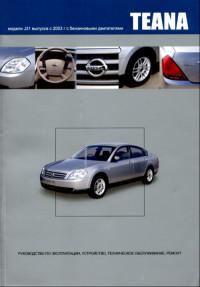
Руководство по эксплуатации, техническому обслуживанию и ремонту автомобиля Nissan Teana серии J31 с 2003 года выпуска с бензиновыми двигателями.
- Автор: —
- Издательство: Автонавигатор
- Год издания: 2008
- Страниц: 632
- Формат: —
- Размер: —
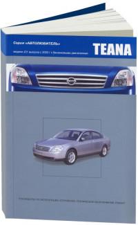
Руководство по эксплуатации, техническому обслуживанию и ремонту автомобиля Nissan Teana серии J31 с 2003 года выпуска с бензиновыми двигателями
- Автор: —
- Издательство: Автонавигатор
- Год издания: —
- Страниц: 376
- Формат: —
- Размер: —
Руководство по эксплуатации, техническому обслуживанию и ремонту автомобиля Nissan Teana серии J32 с 2008 года выпуска с бензиновыми двигателями объемом 2,5/3,5 л.
- Автор: —
- Издательство: Автонавигатор
- Год издания: —
- Страниц: 552
- Формат: —
- Размер: —

Руководство по эксплуатации, техническому обслуживанию и ремонту автомобиля Nissan Teana серии J33 с 2014 года выпуска с бензиновым двигателем объемом 2,5 л.
- Автор: —
- Издательство: Автонавигатор
- Год издания: —
- Страниц: 566
- Формат: —
- Размер: —

Руководство по эксплуатации, техническому обслуживанию и ремонту автомобиля Nissan Teana серии J33 с 2014 года выпуска с бензиновым двигателем объемом 3,5 л.
- Автор: —
- Издательство: Автонавигатор
- Год издания: —
- Страниц: 558
- Формат: —
- Размер: —

NISSAN
TEANA
Модели J32 выпуска с 2008 г. с бензиновыми
двигателями VQ25DE, VQ35DE
Руководство по эксплуатации, устройство,
техническое обслуживание, ремонт
Руководство по эксплуатации
Техническое обслуживание
Механическая часть двигателя
Система смазки и система охлаждения двигателя
Система управления двигателем
Акселератор, топливная система и система выпуска
Бесступенчатая автоматическая коробка передач (вариатор) (CVT)
Передняя ось и подвеска
Задняя ось и подвеска
Тормозная система
Рулевое управление
Система пассивной безопасности
Система вентиляции, отопления и кондиционирования воздуха
Интерьер, экстерьер, двери, люк и система безопасности
Элементы управления для водителя
Информационная система водителя и мультимедийная система
Электрооборудование
Э
■
1
■
2
■
3
5
■
6
8
9
14
16
Nissan Teana 2003-2012 Factory Service Repair Manual PDF.
| Nissan Teana J31 2003-2008 Service Manual 61 Mb Download |
| Nissan Teana J32 2008-2012 Service Manual 62 Mb Download |
| Nissan Teana 2013 Service Manual Also called Nissan Altima 2013 167 Mb Download |
| Nissan Teana 2014 Service Manual Also called Nissan Altima 2014 105 Mb Download |
Comments on this entry are closed.
Pagini
- Nissan Owner Manuals
- Nissan Parts Catalog
- Nissan Service Manuals
-
nekesha
- Администратор
- Сообщения: 1668
- Зарегистрирован: 17 дек 2014, 03:43
- Благодарил (а): 2 раза
- Поблагодарили: 6 раз
Nissan Teana J32 from 2008 / Ниссан Теана J32 c 2008
Руководство по эксплуатации, техобслуживанию и ремонту Nissan Teana J32 / Ниссан Теана J32
Operation, Maintenance and Repair Manual Nissan Teana J32

- Года выпуска: с 2008
Year of release: from 2008
Бензиновые двигатели: VQ25DE, VQ35DE
Gasoline engines: VQ25DE, VQ30DE
- Язык: Русский
Формат: PDF
Размер: 294 Мб
Russian language
Format: PDF
Size: 294 MB
Скачать документацию Nissan Teana J32 / Ниссан Теана J32
Download the documentation of Nissan Teana J32
для распаковки используйте пароль — avto-ok.info
use the password to unpack — avto-ok.info
Crash test

DRIVER CONTROLS
C
D
E
SECTION EXLA
B
EXTERIOR LIGHTING SYSTEM
F
G
H
I
J
K
M
XL
N
O
P
CONTENTS
E
XENON TYPE
BASIC INSPECTION ……………………………… 7
DIAGNOSIS AND REPAIR WORKFLOW ………. 7Work Flow ………………………………………………………..7
INSPECTION AND ADJUSTMENT ………………… 9
ADDITIONAL SERVICE WHEN REPLACING CONTROL UNIT ………………………………………………….9
ADDITIONAL SERVICE WHEN REPLACING CONTROL UNIT : Description …………………………….9ADDITIONAL SERVICE WHEN REPLACING CONTROL UNIT : Special Repair Requirement …….9
CONFIGURATION (HEADLAMP LEVELIZER) ……….9CONFIGURATION (HEADLAMP LEVELIZER) : Description ……………………………………………………….9CONFIGURATION (HEADLAMP LEVELIZER) : Special Repair Requirement ……………………………….9
SENSOR INITIALIZE ……………………………………………9SENSOR INITIALIZE : Description …………………….10SENSOR INITIALIZE : Special Repair Require-ment (HEADLAMP AIMING CONTROL SYSTEM)
….10
FUNCTION DIAGNOSIS …………………………11
HEADLAMP SYSTEM ………………………………….11System Diagram ………………………………………………11System Description ………………………………………….11Component Parts Location ………………………………..12Component Description ……………………………………12
AUTO LIGHT SYSTEM ………………………………..13System Diagram ………………………………………………13System Description ………………………………………….13Component Parts Location ………………………………..14Component Description ……………………………………14
HEADLAMP AIMING CONTROL SYSTEM (AUTO) ……………………………………………………..15
System Diagram ………………………………………………15System Description …………………………………………..15Component Parts Location ………………………………..16Component Description …………………………………….16
FRONT FOG LAMP SYSTEM ………………………17System Diagram ………………………………………………17System Description …………………………………………..17Component Parts Location ………………………………..18Component Description ……………………………………18
TURN SIGNAL AND HAZARD WARNING LAMP SYSTEM ………………………………………….19
System Diagram ………………………………………………19System Description …………………………………………..19Component Parts Location ………………………………..20Component Description ……………………………………20
PARKING, LICENSE PLATE AND TAIL LAMPS SYSTEM ……………………………………….21
System Diagram ………………………………………………21System Description …………………………………………..21Component Parts Location ………………………………..22Component Description ……………………………………22
REAR FOG LAMP SYSTEM ………………………..23System Diagram ………………………………………………23System Description …………………………………………..23Component Parts Location ………………………………..24Component Description ……………………………………24
EXTERIOR LAMP BATTERY SAVER SYS-TEM ………………………………………………………….25
System Diagram ………………………………………………25System Description …………………………………………..25Component Parts Location ………………………………..26Component Description ……………………………………26
DIAGNOSIS SYSTEM (BCM) ………………………27
EXL-1

COMMON ITEM ……………………………………………….. 27COMMON ITEM : CONSULT-III Function (BCM — COMMON ITEM) ……………………………………………. 27
HEADLAMP …………………………………………………….. 28HEADLAMP : CONSULT-III Function (BCM — HEAD LAMP) …………………………………………………. 28
FLASHER ………………………………………………………… 30FLASHER : CONSULT-III Function (BCM — FLASHER) …………………………………………………….. 30
DIAGNOSIS SYSTEM (IPDM E/R) ……………….. 32Diagnosis Description ……………………………………… 32CONSULT-III Function (IPDM E/R) …………………… 34
DIAGNOSIS SYSTEM (HEADLAMP LEVEL-IZER) ………………………………………………………… 37
CONSULT-III Functions (HEADLAMP LEVELIZ-ER) ………………………………………………………………. 37
COMPONENT DIAGNOSIS …………………… 38
B2080 ECU TROUBLE ……………………………….. 38Description …………………………………………………….. 38DTC Logic ……………………………………………………… 38Diagnosis Procedure ………………………………………. 38
B2081 INITIAL NOT DONE …………………………. 39DTC Logic ……………………………………………………… 39Diagnosis Procedure ………………………………………. 39
B2082 SENSOR OUT OF RANGE ……………….. 40DTC Logic ……………………………………………………… 40Diagnosis Procedure ………………………………………. 40
B2083 SEN SIG NOT PLAUSIBLE ………………. 41DTC Logic ……………………………………………………… 41Diagnosis Procedure ………………………………………. 41
B2084 VOLTAGE UNDER LIMIT …………………. 42DTC Logic ……………………………………………………… 42Diagnosis Procedure ………………………………………. 42
B2085 LOWBEAM SIG OPEN LINE …………….. 43Description …………………………………………………….. 43DTC Logic ……………………………………………………… 43Diagnosis Procedure ………………………………………. 43
B2086 FRQ. OVER LIMIT ……………………………. 45Description …………………………………………………….. 45DTC Logic ……………………………………………………… 45Diagnosis Procedure ………………………………………. 45
B2087 SHORT TO GROUND ………………………. 47DTC Logic ……………………………………………………… 47Diagnosis Procedure ………………………………………. 47
B2088 SHORT TO BATTERY ……………………… 48DTC Logic ……………………………………………………… 48Diagnosis Procedure ………………………………………. 48
B208A PARA NOT PROG …………………………… 49DTC Logic ……………………………………………………… 49Diagnosis Procedure ……………………………………….. 49
POWER SUPPLY AND GROUND CIRCUIT ….. 50
BCM (BODY CONTROL MODULE) …………………….. 50BCM (BODY CONTROL MODULE) : Diagnosis Procedure ……………………………………………………… 50
IPDM E/R (INTELLIGENT POWER DISTRIBU-TION MODULE ENGINE ROOM) ………………………… 50
IPDM E/R (INTELLIGENT POWER DISTRIBU-TION MODULE ENGINE ROOM) : Diagnosis Pro-cedure …………………………………………………………… 50
AUTO LEVELIZER CONTROL UNIT …………………… 51AUTO LEVELIZER CONTROL UNIT : Diagnosis Procedure ……………………………………………………… 51
EXTERIOR LAMP FUSE …………………………….. 53Description …………………………………………………….. 53Diagnosis Procedure ……………………………………….. 53
HEADLAMP (HI) CIRCUIT ………………………….. 54Component Function Check …………………………….. 54Diagnosis Procedure ……………………………………….. 54
HEADLAMP (LO) CIRCUIT …………………………. 56Component Function Check …………………………….. 56Diagnosis Procedure ……………………………………….. 56
XENON HEADLAMP ………………………………….. 58Description …………………………………………………….. 58Diagnosis Procedure ……………………………………….. 58
HEADLAMP LEVELIZER CIRCUIT ……………… 60Description …………………………………………………….. 60Component Function Check …………………………….. 60Diagnosis Procedure ……………………………………….. 60
FRONT FOG LAMP CIRCUIT ……………………… 62Component Function Check …………………………….. 62Diagnosis Procedure ……………………………………….. 62
PARKING LAMP CIRCUIT ………………………….. 64Component Function Check …………………………….. 64Diagnosis Procedure ……………………………………….. 64
TURN SIGNAL LAMP CIRCUIT …………………… 66Description …………………………………………………….. 66Component Function Check …………………………….. 66Diagnosis Procedure ……………………………………….. 66
OPTICAL SENSOR ……………………………………. 69Description …………………………………………………….. 69Component Function Check …………………………….. 69Diagnosis Procedure ……………………………………….. 69
HAZARD SWITCH ……………………………………… 72Component Function Check …………………………….. 72Diagnosis Procedure ……………………………………….. 72
EXL-2

C
D
E
F
G
H
I
J
K
M
A
B
XL
N
O
P
E
TAIL LAMP CIRCUIT …………………………………..74Component Function Check ………………………………74Diagnosis Procedure ………………………………………..74
LICENSE PLATE LAMP CIRCUIT …………………76Component Function Check ………………………………76Diagnosis Procedure ………………………………………..76
REAR FOG LAMP CIRCUIT …………………………77Component Function Check ………………………………77Diagnosis Procedure ………………………………………..77
HEADLAMP SYSTEM ………………………………….79Wiring Diagram — HEADLAMP — …………………………79
AUTO LIGHT SYSTEM ………………………………..83Wiring Diagram — AUTO LIGHT SYSTEM — ………….83
FRONT FOG LAMP SYSTEM ……………………….87Wiring Diagram — FRONT FOG LAMP — ………………87
TURN SIGNAL AND HAZARD WARNING LAMP SYSTEM …………………………………………..90
Wiring Diagram — TURN AND HAZARD WARN-ING LAMPS — ………………………………………………….90
PARKING, LICENSE PLATE AND TAIL LAMPS SYSTEM …………………………………………95
Wiring Diagram — PARKING, LICENSE PLATE AND TAIL LAMPS — ………………………………………….95
STOP LAMP ……………………………………………….99Wiring Diagram — STOP LAMP — ………………………..99
BACK-UP LAMP ………………………………………. 102Wiring Diagram — BACK-UP LAMP — ………………… 102
REAR FOG LAMP SYSTEM ………………………. 105Wiring Diagram — REAR FOG LAMP — ……………… 105
ECU DIAGNOSIS ………………………………… 108
BCM (BODY CONTROL MODULE) …………….. 108Reference Value …………………………………………… 108Wiring Diagram — BCM — …………………………………. 131Fail-safe ………………………………………………………. 137DTC Inspection Priority Chart ……………………….. 139DTC Index …………………………………………………… 140
IPDM E/R (INTELLIGENT POWER DISTRI-BUTION MODULE ENGINE ROOM) …………… 142
Reference Value …………………………………………… 142Wiring Diagram — IPDM E/R — ………………………….. 150Fail-safe ………………………………………………………. 153DTC Index …………………………………………………… 155
AUTO LEVELIZER CONTROL UNIT …………… 156Reference Value …………………………………………… 156Wiring Diagram — HEADLAMP AIMING CON-TROL SYSTEM — ………………………………………… 158Fail-safe ………………………………………………………. 161DTC Inspection Priority Chart …………………………. 162
DTC Index …………………………………………………….163
SYMPTOM DIAGNOSIS ………………………. 164
EXTERIOR LIGHTING SYSTEM SYMPTOMS . 164Symptom Table ……………………………………………..164
NORMAL OPERATING CONDITION …………. 167Description …………………………………………………….167
BOTH SIDE HEADLAMPS (HI) ARE NOT TURNED ON …………………………………………… 168
Description …………………………………………………….168Diagnosis Procedure ………………………………………168
BOTH SIDE HEADLAMPS (LO) ARE NOT TURNED ON …………………………………………… 169
Description …………………………………………………….169Diagnosis Procedure ………………………………………169
PARKING, LICENSE PLATE AND TAIL LAMPS ARE NOT TURNED ON ………………… 170
Description …………………………………………………….170Diagnosis Procedure ………………………………………170
BOTH SIDE FRONT FOG LAMPS ARE NOT TURNED ON …………………………………………… 171
Description …………………………………………………….171Diagnosis Procedure ………………………………………171
PRECAUTION …………………………………….. 172
PRECAUTIONS ……………………………………….. 172Precaution for Supplemental Restraint System (SRS) «AIR BAG» and «SEAT BELT PRE-TEN-SIONER» ………………………………………………………172Precautions For Xenon Headlamp Service ………..172
ON-VEHICLE MAINTENANCE ……………… 173
HEADLAMP AIMING ADJUSTMENT …………. 173Description …………………………………………………….173Aiming Adjustment Procedure (Low Beam) ………..174Aiming Adjustment Procedure (High Beam) ……….175
FRONT FOG LAMP AIMING ADJUSTMENT . 178Description …………………………………………………….178Aiming Adjustment Procedure ………………………….178
ON-VEHICLE REPAIR …………………………. 180
FRONT COMBINATION LAMP …………………. 180Exploded View ……………………………………………….180Removal and Installation …………………………………181Replacement …………………………………………………181Disassembly and Assembly ……………………………..182
FRONT FOG LAMP …………………………………. 183Exploded View ……………………………………………….183Removal and Installation …………………………………183Replacement …………………………………………………183
EXL-3

OPTICAL SENSOR ………………………………….. 185Exploded View ……………………………………………….185Removal and Installation …………………………………185
LIGHTING & TURN SIGNAL SWITCH ………… 186Exploded View ……………………………………………….186Removal and Installation …………………………………186
HAZARD SWITCH ……………………………………. 187Exploded View ……………………………………………….187Removal and Installation …………………………………187
SIDE TURN SIGNAL LAMP ………………………. 188Exploded View ……………………………………………….188Removal and Installation …………………………………188
AUTO LEVELIZER CONTROL UNIT ………….. 190Exploded View ……………………………………………….190Removal and Installation …………………………………190
REAR COMBINATION LAMP ……………………. 191Exploded View ……………………………………………….191Removal and Installation …………………………………191Replacement …………………………………………………192
HIGH-MOUNTED STOP LAMP ………………….. 193Exploded View ……………………………………………….193Removal and Installation …………………………………193
REAR FOG LAMP ……………………………………. 194Exploded View ……………………………………………….194Removal and Installation …………………………………194Replacement …………………………………………………194
LICENSE PLATE LAMP ……………………………. 195Exploded View ……………………………………………….195Removal and Installation …………………………………195Replacement …………………………………………………195
SERVICE DATA AND SPECIFICATIONS (SDS) ………………………………………………….197
SERVICE DATA AND SPECIFICATIONS (SDS) ………………………………………………………. 197
Bulb Specifications …………………………………………197
HALOGEN TYPE
BASIC INSPECTION …………………………….198
DIAGNOSIS AND REPAIR WORKFLOW ……. 198Work Flow ……………………………………………………..198
FUNCTION DIAGNOSIS ……………………….200
HEADLAMP SYSTEM ………………………………. 200System Diagram …………………………………………….200System Description …………………………………………200Component Parts Location ………………………………201Component Description ………………………………….201
AUTO LIGHT SYSTEM ……………………………… 202System Diagram …………………………………………….202
System Description ……………………………………….. 202Component Parts Location …………………………….. 203Component Description …………………………………. 203
FRONT FOG LAMP SYSTEM ……………………..204System Diagram …………………………………………… 204System Description ……………………………………….. 204Component Parts Location …………………………….. 205Component Description …………………………………. 205
TURN SIGNAL AND HAZARD WARNING LAMP SYSTEM …………………………………………206
System Diagram …………………………………………… 206System Description ……………………………………….. 206Component Parts Location …………………………….. 207Component Description …………………………………. 207
PARKING, LICENSE PLATE AND TAIL LAMPS SYSTEM ……………………………………….208
System Diagram …………………………………………… 208System Description ……………………………………….. 208Component Parts Location …………………………….. 209Component Description …………………………………. 209
REAR FOG LAMP SYSTEM ……………………….210System Diagram …………………………………………… 210System Description ……………………………………….. 210Component Parts Location …………………………….. 211Component Description …………………………………. 211
EXTERIOR LAMP BATTERY SAVER SYS-TEM ………………………………………………………….212
System Diagram …………………………………………… 212System Description ……………………………………….. 212Component Parts Location …………………………….. 213Component Description …………………………………. 213
DIAGNOSIS SYSTEM (BCM) ………………………214
COMMON ITEM ………………………………………………. 214COMMON ITEM : CONSULT-III Function (BCM — COMMON ITEM) ………………………………………….. 214
HEADLAMP ……………………………………………………. 215HEADLAMP : CONSULT-III Function (BCM — HEAD LAMP) ……………………………………………….. 215
FLASHER ………………………………………………………. 217FLASHER : CONSULT-III Function (BCM — FLASHER) …………………………………………………… 217
DIAGNOSIS SYSTEM (IPDM E/R) ……………….219Diagnosis Description ……………………………………. 219CONSULT-III Function (IPDM E/R) …………………. 221
COMPONENT DIAGNOSIS ………………….224
POWER SUPPLY AND GROUND CIRCUIT ….224
BCM (BODY CONTROL MODULE) …………………… 224BCM (BODY CONTROL MODULE) : Diagnosis Procedure ……………………………………………………. 224
EXL-4

C
D
E
F
G
H
I
J
K
M
A
B
XL
N
O
P
E
IPDM E/R (INTELLIGENT POWER DISTRIBU-TION MODULE ENGINE ROOM) ………………………. 224
IPDM E/R (INTELLIGENT POWER DISTRIBU-TION MODULE ENGINE ROOM) : Diagnosis Pro-cedure …………………………………………………………. 224
EXTERIOR LAMP FUSE ……………………………. 226Description …………………………………………………… 226Diagnosis Procedure ……………………………………… 226
HEADLAMP (HI) CIRCUIT …………………………. 227Component Function Check ……………………………. 227Diagnosis Procedure ……………………………………… 227
HEADLAMP (LO) CIRCUIT ………………………… 229Component Function Check ……………………………. 229Diagnosis Procedure ……………………………………… 229
FRONT FOG LAMP CIRCUIT …………………….. 231Component Function Check ……………………………. 231Diagnosis Procedure ……………………………………… 231
PARKING LAMP CIRCUIT …………………………. 233Component Function Check ……………………………. 233Diagnosis Procedure ……………………………………… 233
TURN SIGNAL LAMP CIRCUIT ………………….. 235Description …………………………………………………… 235Component Function Check ……………………………. 235Diagnosis Procedure ……………………………………… 235
OPTICAL SENSOR …………………………………… 238Description …………………………………………………… 238Component Function Check ……………………………. 238Diagnosis Procedure ……………………………………… 238
HAZARD SWITCH …………………………………….. 241Component Function Check ……………………………. 241Diagnosis Procedure ……………………………………… 241
TAIL LAMP CIRCUIT ………………………………… 243Component Function Check ……………………………. 243Diagnosis Procedure ……………………………………… 243
LICENSE PLATE LAMP CIRCUIT ………………. 245Component Function Check ……………………………. 245Diagnosis Procedure ……………………………………… 245
REAR FOG LAMP CIRCUIT ………………………. 246Component Function Check ……………………………. 246Diagnosis Procedure ……………………………………… 246
HEADLAMP SYSTEM ……………………………….. 248Wiring Diagram — HEADLAMP — ………………………. 248
AUTO LIGHT SYSTEM ……………………………… 252Wiring Diagram — AUTO LIGHT SYSTEM — ……….. 252
HEADLAMP AIMING CONTROL SYSTEM (MANUAL) ……………………………………………….. 256
Description …………………………………………………… 256
Wiring Diagram — HEADLAMP AIMING CON-TROL SYSTEM (MANUAL) — ……………………………256Component Inspection …………………………………….257
FRONT FOG LAMP SYSTEM ……………………. 259Wiring Diagram — FRONT FOG LAMP — …………….259
TURN SIGNAL AND HAZARD WARNING LAMP SYSTEM ……………………………………….. 262
Wiring Diagram — TURN AND HAZARD WARN-ING LAMPS — …………………………………………………262
PARKING, LICENSE PLATE AND TAIL LAMPS SYSTEM …………………………………….. 267
Wiring Diagram — PARKING, LICENSE PLATE AND TAIL LAMPS — ………………………………………..267
STOP LAMP ……………………………………………. 271Wiring Diagram — STOP LAMP — ……………………….271
BACK-UP LAMP ……………………………………… 274Wiring Diagram — BACK-UP LAMP — ………………….274
REAR FOG LAMP SYSTEM ……………………… 277Wiring Diagram — REAR FOG LAMP — ……………….277
ECU DIAGNOSIS ………………………………… 280
BCM (BODY CONTROL MODULE) …………… 280Reference Value …………………………………………….280Wiring Diagram — BCM — ………………………………….303Fail-safe ………………………………………………………..309DTC Inspection Priority Chart ………………………..311DTC Index …………………………………………………….312
IPDM E/R (INTELLIGENT POWER DISTRI-BUTION MODULE ENGINE ROOM) ………….. 314
Reference Value …………………………………………….314Wiring Diagram — IPDM E/R — …………………………..322Fail-safe ………………………………………………………..325DTC Index …………………………………………………….327
SYMPTOM DIAGNOSIS ………………………. 328
EXTERIOR LIGHTING SYSTEM SYMPTOMS . 328Symptom Table ……………………………………………..328
BOTH SIDE HEADLAMPS (HI) ARE NOT TURNED ON …………………………………………… 331
Description …………………………………………………….331Diagnosis Procedure ………………………………………331
BOTH SIDE HEADLAMPS (LO) ARE NOT TURNED ON …………………………………………… 332
Description …………………………………………………….332Diagnosis Procedure ………………………………………332
PARKING, LICENSE PLATE AND TAIL LAMPS ARE NOT TURNED ON ………………… 333
Description …………………………………………………….333Diagnosis Procedure ………………………………………333
EXL-5

BOTH SIDE FRONT FOG LAMPS ARE NOT TURNED ON ……………………………………………. 334
Description …………………………………………………….334Diagnosis Procedure ………………………………………334
PRECAUTION ……………………………………..335
PRECAUTIONS ……………………………………….. 335Precaution for Supplemental Restraint System (SRS) «AIR BAG» and «SEAT BELT PRE-TEN-SIONER» ……………………………………………………….335
ON-VEHICLE MAINTENANCE ………………336
HEADLAMP AIMING ADJUSTMENT …………. 336Description …………………………………………………….336Aiming Adjustment Procedure (Low Beam) ………..337Aiming Adjustment Procedure (High Beam) ……….338
FRONT FOG LAMP AIMING ADJUSTMENT . 341Description …………………………………………………….341Aiming Adjustment Procedure ………………………….341
ON-VEHICLE REPAIR ………………………….343
FRONT COMBINATION LAMP ………………….. 343Exploded View ……………………………………………….343Removal and Installation …………………………………343Replacement …………………………………………………344Disassembly and Assembly ……………………………..344
FRONT FOG LAMP ………………………………….. 346Exploded View ……………………………………………….346Removal and Installation …………………………………346Replacement …………………………………………………346
OPTICAL SENSOR ………………………………….. 348Exploded View ……………………………………………….348Removal and Installation …………………………………348
LIGHTING & TURN SIGNAL SWITCH ………… 349
Exploded View ……………………………………………… 349Removal and Installation ………………………………… 349
HEADLAMP AIMING SWITCH …………………….350Exploded View ……………………………………………… 350Removal and Installation ………………………………… 350
HAZARD SWITCH ……………………………………..351Exploded View ……………………………………………… 351Removal and Installation ………………………………… 351
SIDE TURN SIGNAL LAMP ………………………..352Exploded View ……………………………………………… 352Removal and Installation ………………………………… 352
REAR COMBINATION LAMP ……………………..354Exploded View ……………………………………………… 354Removal and Installation ………………………………… 354Replacement ………………………………………………… 355
HIGH-MOUNTED STOP LAMP ……………………356Exploded View ……………………………………………… 356Removal and Installation ………………………………… 356
REAR FOG LAMP ……………………………………..357Exploded View ……………………………………………… 357Removal and Installation ………………………………… 357Replacement ………………………………………………… 357
LICENSE PLATE LAMP ……………………………..358Exploded View ……………………………………………… 358Removal and Installation ………………………………… 358Replacement ………………………………………………… 358
SERVICE DATA AND SPECIFICATIONS (SDS) …………………………………………………360
SERVICE DATA AND SPECIFICATIONS (SDS) ……………………………………………………….360
Bulb Specifications ………………………………………… 360
EXL-6

DIAGNOSIS AND REPAIR WORKFLOW[XENON TYPE]
C
D
E
F
G
H
I
J
K
M
A
B
XL
N
O
P
< BASIC INSPECTION >
E
BASIC INSPECTIONDIAGNOSIS AND REPAIR WORKFLOW
Work Flow INFOID:0000000003773518
OVERALL SEQUENCE
DETAILED FLOW
1.INTERVIEW FOR MALFUNCTION
Interview the symptom to the customer.
JPLIA0313GB
EXL-7

[XENON TYPE]DIAGNOSIS AND REPAIR WORKFLOW
< BASIC INSPECTION >>> GO TO 2.
2.SYMPTOM CHECK
Check the symptom from the customer’s information.
>> GO TO 3.
3.BASIC INSPECTION
Check the operation of each part. Check that any symptom occurs other than the interviewed symptom.
>> GO TO 4.
4.SELF-DIAGNOSIS WITH CONSULT-III
Perform the self-diagnosis with CONSULT-III. Check that any DTC is detected.Is any DTC detected?YES >> GO TO 5.NO >> GO TO 6.
5.TROUBLE DIAGNOSIS BY DTC
Perform the trouble diagnosis for the detected DTC. Specify the malfunctioning part.
>> GO TO 9.
6.FAIL-SAFE ACTIVATION CHECK
Check that the symptom is applied to the fail-safe activation.Does the fail-safe activate?YES >> GO TO 7.NO >> GO TO 8.
7.SYSTEM DIAGNOSIS
Perform the system diagnosis for the system that the fail-safe activates. Specify the malfunctioning part.
>> GO TO 9.
8.SYMPTOM DIAGNOSIS
Perform the symptom diagnosis. Specify the malfunctioning part.
>> GO TO 9.
9.MALFUNCTION PART REPAIR
Repair or replace the malfunctioning part.
>> GO TO 10.
10.REPAIR CHECK (SELF-DIAGNOSIS WITH CONSULT-III)
Perform the self-diagnosis with CONSULT-III. Check that any DTC is not detected. Erase DTC if DTC isdetected before the repair. Check that DTC is not detected again.Is any DTC detected?YES >> GO TO 5.NO >> GO TO 11.
11.REPAIR CHECK (OPERATION CHECK)
Check the operation of each part.Does it operate normally?YES >> INSPECTION ENDNO >> GO TO 3.
EXL-8

INSPECTION AND ADJUSTMENT[XENON TYPE]
C
D
E
F
G
H
I
J
K
M
A
B
XL
N
O
P
< BASIC INSPECTION >
E
INSPECTION AND ADJUSTMENTADDITIONAL SERVICE WHEN REPLACING CONTROL UNIT
ADDITIONAL SERVICE WHEN REPLACING CONTROL UNIT : DescriptionINFOID:0000000003894984
CAUTION:• When replacing the auto levelizer control unit, you must perform “WRITE CONFIGURATION” with
CONSULT-III.- Complete the procedure of “WRITE CONFIGURATION” in order.• When replacing the auto levelizer control unit, perform “SENSOR INITIALIZE” with CONSULT-III.
ADDITIONAL SERVICE WHEN REPLACING CONTROL UNIT : Special Repair Re-quirement INFOID:0000000003894985
1.WRITING VEHICLE SPECIFICATION
CONSULT-III ConfigurationPerform “WRITE CONFIGURATION” to write vehicle specification. Refer to EXL-9, «CONFIGURATION(HEADLAMP LEVELIZER) : Special Repair Requirement».
>> GO TO 2.
2.SENSOR INITIALIZE
CONSULT-III Work supportPerform “SENSOR INITIALIZE”. Refer to EXL-10, «SENSOR INITIALIZE : Special Repair Requirement(HEADLAMP AIMING CONTROL SYSTEM)».
>> WORK ENDCONFIGURATION (HEADLAMP LEVELIZER)
CONFIGURATION (HEADLAMP LEVELIZER) : Description INFOID:0000000003894986
Vehicle specification needs to be written with CONSULT-III because it is not written after replacing the autolevelizer control unit.
CAUTION:• When replacing the auto levelizer control unit, you must perform “WRITE CONFIGURATION” with
CONSULT-III.• Complete the procedure of “WRITE CONFIGURATION” in order.
CONFIGURATION (HEADLAMP LEVELIZER) : Special Repair RequirementINFOID:0000000003894987
1.WRITE CONFIGURATION
CONSULT-III Configuration1. Select “WRITE CONFIGURATION”.2. Select “Setting change”.3. When “COMMAND FINISHED”, select “END”.
>> WORK ENDSENSOR INITIALIZE
Function Description
WRITE CONFIGURATION Writes the vehicle configuration automatically.
EXL-9

[XENON TYPE]INSPECTION AND ADJUSTMENT
< BASIC INSPECTION >
SENSOR INITIALIZE : Description INFOID:0000000003774311
HEADLAMP AIMING CONTROL SYSTEMPerform the sensor initialize when installing, removing and replacing the auto levelizer control unit and sus-pension components.
SENSOR INITIALIZE : Special Repair Requirement (HEADLAMP AIMING CONTROL SYSTEM) INFOID:0000000003774312
1.VEHICLE CONDITION CHECK
1. Park the vehicle in the straight-forward position.2. Unload the vehicle (no passenger aboard).
>> GO TO 2.
2.SENSOR INITIALIZE
CONSULT-III WORK SUPPORT1. Select «SENSOR INITIALIZE» of HEADLAMP LEVELIZER work support item.2. Select «START».3. When «INITIALIZE COMPLETE», select «END».
CAUTION:If «INITIALIZE NOT DONE» is indicated, auto levelizer control unit detects that the sensor lever sig-nal changes. The sensor initialize is cancelled. In this case, turn the ignition switch OFF to preventthe vehicle from the height change. Perform the sensor initialize again.
Is the sensor initialize completed?YES >> GO TO 3.NO >> Perform the sensor initialize again.
3.SELF-DIAGNOSIS RESULT CHECK
Perform the self-diagnosis with CONSULT-III. Check that any DTC is not detected.Is any DTC detected?YES >> GO TO 2.NO >> Sensor initialize completed
EXL-10

HEADLAMP SYSTEM[XENON TYPE]
C
D
E
F
G
H
I
J
K
M
A
B
XL
N
O
P
< FUNCTION DIAGNOSIS >
E
FUNCTION DIAGNOSISHEADLAMP SYSTEM
System Diagram INFOID:0000000003774356
System Description INFOID:0000000003774357
OUTLINEHeadlamp is controlled by combination switch reading function and headlamp control function of BCM, andrelay control function of IPDM E/R.
HEADLAMP (LO) OPERATION • BCM detects the combination switch condition with the combination switch reading function.• BCM transmits the low beam request signal to IPDM E/R with CAN communication according to the head-
lamp (LO) ON condition.
Headlamp (LO) ON condition- Lighting switch 2ND- Lighting switch AUTO (auto light function ON judgment)• IPDM E/R turns the integrated headlamp low relay ON, and turns the headlamp ON according to the low
beam request signal.
HEADLAMP (HI) OPERATION• BCM transmits the high beam request signal to IPDM E/R and the combination meter with CAN communica-
tion according to the headlamp (HI) ON condition.
Headlamp (HI) ON condition- Lighting switch HI with the lighting switch 2ND or AUTO (auto light function ON judgment)- Lighting switch PASS• Combination meter turns the high beam indicator lamp ON according to the high beam request signal. • IPDM E/R turns the integrated headlamp high relay ON, and turns the headlamp ON according to the high
beam request signal.
JPLIA0168GB
EXL-11

[XENON TYPE]HEADLAMP SYSTEM
< FUNCTION DIAGNOSIS >
Component Parts Location INFOID:0000000003774358
Component Description INFOID:0000000003774359
1. Headlamp (HI) 2. Headlamp (LO) 3. Combination switch
4. IPDM E/R 5. BCM 6. High beam indicator lamp
A. Engine room (LH) B. Behind the combination meter C. On the combination meter
JPLIA1118ZZ
Part Description
BCM
• Detects each switch condition by the combination switch reading function.• Judges that the headlamp is turned ON according to the vehicle condition. — Requests the headlamp relay (HI/LO) ON to IPDM E/R (with CAN communication). — Requests the high beam indicator lamp ON to the combination meter (with CAN
communication).
IPDM E/RControls the integrated relay, and supplies voltage to the load according to the request from BCM (with CAN communication).
Combination switch(Lighting & turn signal switch)
Refer to BCS-8, «System Diagram».
Combination meter(High beam indicator lamp)
Turns the high beam indicator lamp ON according to the request from BCM (with CAN communication).
EXL-12

AUTO LIGHT SYSTEM[XENON TYPE]
C
D
E
F
G
H
I
J
K
M
A
B
XL
N
O
P
< FUNCTION DIAGNOSIS >
E
AUTO LIGHT SYSTEM
System Diagram INFOID:0000000003773527
System Description INFOID:0000000003773528
OUTLINE• Auto light system is controlled by each function of BCM and IPDM E/R.
Control by BCM- Combination switch reading function- Headlamp control function- Auto light function- Delay timer function
Control by IPDM E/R- Relay control function• Auto light system has the auto light function and the delay timer function.- Auto light function turns the exterior lamps* and each illumination ON/OFF automatically according to the
outside brightness.- When auto light system turns the exterior lamps ON with the ignition switch OFF, delay timer function turns
the exterior lamps OFF depending on the vehicle condition with the auto light function after a certain periodof time.
*: Headlamp (LO/HI), parking lamp, tail lamp and front fog lamp (Headlamp HI and front fog lamp depend onthe combination switch condition.)
AUTO LIGHT FUNCTION• BCM detects the combination switch condition with the combination switch reading function.• BCM supplies voltage to optical sensor when the ignition switch is turned ON or ACC.• Optical sensor converts outside brightness (lux) to voltage and transmits the optical sensor signal to BCM.• BCM judges outside brightness from the optical sensor signal and judges ON/OFF condition of the exterior
lamp and each illumination according to the outside brightness. • BCM transmits each request signal to IPDM E/R with CAN communication according to ON/OFF condition
by the auto light function.NOTE:ON/OFF timing differs based on the sensitivity from the setting. The setting can be set by CONSULT-III. Referto EXL-28, «HEADLAMP : CONSULT-III Function (BCM — HEAD LAMP)».
DELAY TIMER FUNCTIONBCM turns the exterior lamp OFF depending on the vehicle condition with the auto light function when the igni-tion switch is turned OFF.• Turns the exterior lamp OFF 5 minutes after detecting that any door opens (Door switch ON).• Turns the exterior lamp OFF a certain period of time* after closing all doors (Door switch ON→OFF).
JPLIA0804GB
EXL-13

[XENON TYPE]AUTO LIGHT SYSTEM
< FUNCTION DIAGNOSIS >• Turns the exterior lamp OFF with the ignition switch ACC or the light switch OFF.*: The preset time is 45 seconds. The timer operating time can be set by CONSULT-III. Refer to EXL-28,»HEADLAMP : CONSULT-III Function (BCM — HEAD LAMP)».NOTE:When any position other than the light switch AUTO is set, the auto light system function switches to the exte-rior lamp battery saver function.
Component Parts Location INFOID:0000000003773529
Component Description INFOID:0000000003773530
1. Combination switch 2. Optical sensor 3. IPDM E/R
4. BCM
A. Instrument upper panel (RH) B. Engine room (LH) C. Behind the combination meter
JPLIA1119ZZ
Part Description
BCM
• Detects each switch condition by the combination switch reading function.• Judges the outside brightness from the optical sensor signal.• Judges the OFF timing according to the vehicle condition.• Judges the ON/OFF status of the exterior lamp and each illumination according to the
outside brightness and the vehicle condition.Requests ON/OFF of each relay to IPDM E/R (with CAN communication).
IPDM E/RControls the integrated relay, and supplies voltage to the load according to the request from BCM (with CAN communication).
Combination switch(Lighting & turn signal switch)
Refer to BCS-8, «System Diagram».
Optical sensor Refer to EXL-69, «Description».
EXL-14

HEADLAMP AIMING CONTROL SYSTEM (AUTO)[XENON TYPE]
C
D
E
F
G
H
I
J
K
M
A
B
XL
N
O
P
< FUNCTION DIAGNOSIS >
E
HEADLAMP AIMING CONTROL SYSTEM (AUTO)
System Diagram INFOID:0000000003774320
System Description INFOID:0000000003774321
OUTLINE• Headlamp aiming control system is controlled by auto levelizer control unit.• Auto levelizer control unit controls the headlamp light axis height appropriately depending on the vehicle rear
height.• Auto levelizer control unit detects the vehicle condition necessary for the aiming motor control with the fol-
lowing signals.- Sensor lever signal (detected by the sensor lever)- Tail lamp signal (inputted from IPDM E/R)- Vehicle speed signal (8-pulse) (inputted from combination meter)
HEADLAMP AUTO AIMING OPERATION• Auto levelizer control unit calculates vehicle pitch angle from sensor lever signal and determines the neces-
sary correction to compensate the deviation from standard light axis position.• Auto levelizer control unit outputs aiming motor drive signal when operating conditions are satisfied.
Operating condition- Ignition switch ON- Tail lamp ON• Auto levelizer control unit changes the aiming motor drive signal when any of the correcting condition is
detected. Output is maintained if other condition is detected.
Correcting condition- Tail lamp is turned ON.- Vehicle posture becomes stable after the vehicle posture change is detected with the tail lamp ON and the
vehicle stopped.- Vehicle speed is maintained with the tail lamp ON and the vehicle driven.CAUTION:Adjusted axis position may differ from the preset position although the headlamp auto aiming acti-vates properly when the suspension is replaced or worn.
JPLIA0171GB
EXL-15

[XENON TYPE]HEADLAMP AIMING CONTROL SYSTEM (AUTO)
< FUNCTION DIAGNOSIS >
Component Parts Location INFOID:0000000003774322
Component Description INFOID:0000000003774323
1. Combination meter 2. Aiming motor 3. IPDM E/R
4. Auto levelizer control unit
A. Front combination lamp (back) B. Engine room (LH) C. Left rear suspension member
JPLIA1148ZZ
Part Description
Auto levelizer control unit Refer to EXL-60, «Description».
Headlamp aiming motor Refer to EXL-60, «Description».
IPDM E/R Outputs the tail lamp signal to auto levelizer control unit.
Combination meter Outputs the vehicle speed signal (8-pulse) to auto levelizer control unit.
EXL-16

FRONT FOG LAMP SYSTEM[XENON TYPE]
C
D
E
F
G
H
I
J
K
M
A
B
XL
N
O
P
< FUNCTION DIAGNOSIS >
E
FRONT FOG LAMP SYSTEM
System Diagram INFOID:0000000003773531
System Description INFOID:0000000003773532
OUTLINEFront fog lamp is controlled by combination switch reading function and front fog lamp control function of BCM,and relay control function of IPDM E/R.
FRONT FOG LAMP OPERATION • BCM detects the combination switch condition by the combination switch reading function.• BCM transmits the front fog light request signal to IPDM E/R with CAN communication according to the front
fog lamp ON condition.
Front fog lamp ON condition- Front fog lamp switch ON- Lighting switch 1ST, 2ND or AUTO (auto light function ON judgment)• IPDM E/R turns the integrated front fog lamp relay ON, and turns the front fog lamp ON according to the
front fog light request signal.• Combination meter turns the front fog lamp indicator lamp ON according to the front fog light request signal.
JPLIA1083GB
EXL-17

[XENON TYPE]FRONT FOG LAMP SYSTEM
< FUNCTION DIAGNOSIS >
Component Parts Location INFOID:0000000003773533
Component Description INFOID:0000000003773534
1. Front fog lamp 2. Combination switch 3. IPDM E/R
4. BCM 5. Front fog lamp indicator lamp
A. Engine room (LH) B. Behind the combination meter C. On the combination meter
JPLIA1121ZZ
Part Description
BCM• Detects each switch condition by the combination switch reading function.• Judges the front fog lamp ON/OFF status according to the vehicle condition. — Requests the front fog lamp relay ON to IPDM E/R (with CAN communication).
IPDM E/RControls the integrated relay and supplies voltage to the load according to the request from BCM (with CAN communication).
Combination switch(Lighting & turn signal switch)
Refer to BCS-8, «System Diagram».
Combination meter(Front fog lamp indicator lamp)
Turn the front fog lamp indicator lamp ON according to the request from BCM (with CAN communication).
EXL-18

TURN SIGNAL AND HAZARD WARNING LAMP SYSTEM[XENON TYPE]
C
D
E
F
G
H
I
J
K
M
A
B
XL
N
O
P
< FUNCTION DIAGNOSIS >
E
TURN SIGNAL AND HAZARD WARNING LAMP SYSTEM
System Diagram INFOID:0000000003773535
System Description INFOID:0000000003773536
OUTLINETurn signal lamp and the hazard warning lamp is controlled by combination switch reading function and theflasher control function of BCM.
TURN SIGNAL LAMP OPERATION• BCM detects the combination switch condition by the combination switch reading function.• BCM supplies voltage to the right (left) turn signal lamp circuit when the ignition switch is turned ON and the
turn signal switch is in the right (left) position. BCM blinks the turn signal lamp.
HAZARD WARNING LAMP OPERATIONBCM supplies voltage to both turn signal lamp circuit when the hazard switch is turned ON. BCM blinks thehazard warning lamp.
TURN SIGNAL INDICATOR LAMP AND TURN SIGNAL SOUND OPERATION• BCM transmits the turn indicator signal to the combination meter with CAN communication while the turn sig-
nal lamp and the hazard warning lamp are operating.• Combination meter outputs the turn signal sound with the integrated buzzer while blinking the turn signal
indicator lamp according to the turn indicator signal.
HIGH FLASHER OPERATION (FAIL-SAFE)• BCM detects the turn signal lamp circuit status by the terminal current value.• BCM increases the turn signal lamp blinking speed if the bulb or harness open is detected with the turn sig-
nal lamp operating.NOTE:The blinking speed is normal while operating the hazard warning lamp.
JPLIA0180GB
EXL-19

[XENON TYPE]TURN SIGNAL AND HAZARD WARNING LAMP SYSTEM
< FUNCTION DIAGNOSIS >
Component Parts Location INFOID:0000000003773537
Component Description INFOID:0000000003773538
1. Hazard switch 2. Front turn signal lamp 3. Combination switch
4. Side turn signal lamp 5. Rear turn signal lamp 6. BCM
7. Turn signal indicator lamp
A. Behind the combination meter B. On the combination meter
JPLIA1122ZZ
Part Description
BCM
• Detects each switch condition by the combination switch reading function.• Judges the blinks of the turn signal lamp and the hazard warning lamp from each
switch status. The applicable turn signal lamp blinks.• Requests the turn signal indicator lamp blink to the combination meter (with CAN
communication).
Combination switch(Lighting & turn signal switch)
Refer to BCS-8, «System Diagram».
Hazard switch Inputs the hazard switch ON/OFF signal to BCM.
Combination meter(Turn signal indicator lamp & buzzer)
Blinks the turn signal indicator lamp and outputs the turn signal operating sound with integrated buzzer according to the request from BCM (with CAN communication).
EXL-20

PARKING, LICENSE PLATE AND TAIL LAMPS SYSTEM[XENON TYPE]
C
D
E
F
G
H
I
J
K
M
A
B
XL
N
O
P
< FUNCTION DIAGNOSIS >
E
PARKING, LICENSE PLATE AND TAIL LAMPS SYSTEM
System Diagram INFOID:0000000003773539
System Description INFOID:0000000003773540
OUTLINEParking, license plate and tail lamps are controlled by combination switch reading function and headlamp con-trol function of BCM, and relay control function of IPDM E/R.
PARKING, LICENSE PLATE AND TAIL LAMPS OPERATION • BCM detects the combination switch condition by the combination switch reading function.• BCM transmits the position light request signal to IPDM E/R and the combination meter with CAN communi-
cation according to the ON/OFF condition of the parking, license plate and tail lamps.
Parking, license plate and tail lamps ON condition- Lighting switch 1ST- Lighting switch 2ND- Lighting switch AUTO (auto light function ON judgment)• IPDM E/R turns the integrated tail lamp relay ON and turns the parking lamp, license plate and tail lamps ON
according to the position light request signal.• Combination meter turns the tail lamp indicator lamp ON according to the position light request signal.
JPLIA0181GB
EXL-21

[XENON TYPE]PARKING, LICENSE PLATE AND TAIL LAMPS SYSTEM
< FUNCTION DIAGNOSIS >
Component Parts Location INFOID:0000000003773541
Component Description INFOID:0000000003773542
1. Parking lamp 2. Combination switch 3. Tail lamp
4. License plate lamp 5. IPDM E/R 6. BCM
7. Tail lamp indicator lamp
A. Engine room (LH) B. Behind the combination meter C. On the combination meter
JPLIA1123ZZ
Part Description
BCM
• Detects each switch condition by the combination switch reading function.• Judges the ON/OFF status of the parking, license plate and tail lamps according to
the vehicle condition.- Requests the tail lamp relay ON to IPDM E/R (with CAN communication). — Requests the tail lamp indicator lamp ON to the combination meter (with CAN com-
munication).
IPDM E/RControls the integrated relay and supplies voltage to the load according to the request from BCM (with CAN communication).
Combination switch(Lighting & turn signal switch)
Refer to BCS-8, «System Diagram».
Combination meter(Tail lamp indicator lamp)
Turns the tail lamp indicator lamp ON according to the request from BCM (with CAN communication).
EXL-22

REAR FOG LAMP SYSTEM[XENON TYPE]
C
D
E
F
G
H
I
J
K
M
A
B
XL
N
O
P
< FUNCTION DIAGNOSIS >
E
REAR FOG LAMP SYSTEM
System Diagram INFOID:0000000003811061
System Description INFOID:0000000003811062
OUTLINERear fog lamp is controlled with the combination switch reading function and the rear fog lamp control functionof BCM.
REAR FOG LAMP OPERATION• BCM detects the condition of the combination switch by the combination switch reading function.• BCM supplies voltage to rear fog lamp according to the rear fog lamp ON condition.
Rear fog lamp ON condition- Rear fog lamp switch signal is input with front fog lamp ON and rear fog lamp OFF
Rear fog lamp switch ON with any of following condition.- Lighting switch 2ND- Lighting switch 1ST, and front fog lamp switch ON• BCM transmits the rear fog lamp status signal to the combination meter with CAN communication. • Combination meter turns the rear fog lamp indicator lamp ON according to the rear fog lamp status signal.
JPLIA0179GB
EXL-23

[XENON TYPE]REAR FOG LAMP SYSTEM
< FUNCTION DIAGNOSIS >
Component Parts Location INFOID:0000000003811063
Component Description INFOID:0000000003811064
1. Combination switch 2. Rear fog lamp 3. BCM
4. Rear fog lamp indicator lamp
A. Behind the combination meter B. On the combination meter
JPLIA1125ZZ
Part Description
BCM
• Detects each switch condition by the combination switch reading function. • Judges that the rear fog lamp is turned ON according to the vehicle status- Supplies voltage to the rear fog lamp- Requests the rear fog lamp indicator lamp ON to the combination meter (with CAN
communication).
Combination switch(Lighting & turn signal switch)
Refer to BCS-8, «System Diagram».
Combination meter(Rear fog lamp indicator lamp)
Turns the rear fog lamp indicator lamp ON according to the request from BCM (with CAN communication).
EXL-24

EXTERIOR LAMP BATTERY SAVER SYSTEM[XENON TYPE]
C
D
E
F
G
H
I
J
K
M
A
B
XL
N
O
P
< FUNCTION DIAGNOSIS >
E
EXTERIOR LAMP BATTERY SAVER SYSTEM
System Diagram INFOID:0000000003773543
System Description INFOID:0000000003773544
OUTLINE• Exterior lamp battery saver system is controlled by each function of BCM and IPDM E/R.
Control by BCM- Combination switch reading function- Headlamp control function- Exterior lamp battery saver function
Control by IPDM E/R- Relay control function• BCM turns the exterior lamp* OFF after a period of time to prevent the battery from over-discharge when the
ignition switch is turned OFF with the exterior lamp ON.*: Headlamp (LO/HI), parking lamp, tail lamp, license plate lamp, front fog lamp and rear fog lamp.
EXTERIOR LAMP BATTERY SAVER ACTIVATIONBCM activates the timer and turns the exterior lamp OFF 5 minutes after the ignition switch is turned from ON→ OFF with the exterior lamps ON. NOTE:• Headlamp control function turns the exterior lamps ON normally when the ignition switch is turned ACC or
the engine started (both before and after the exterior lamp battery saver is turned OFF).• The timer starts at the time that the lighting switch is turned from OFF → 1ST or 2ND with the exterior lamp
OFF.
JPLIA1084GB
EXL-25

[XENON TYPE]EXTERIOR LAMP BATTERY SAVER SYSTEM
< FUNCTION DIAGNOSIS >
Component Parts Location INFOID:0000000003773545
Component Description INFOID:0000000003773546
1. Combination switch 2. IPDM E/R 3. BCM
A. Engine room (LH) B. Behind the combination meter
JPLIA1124ZZ
Part Description
BCM
• Detects each switch condition by the combination switch reading function.• Activates the battery saver to turn the exterior lamps OFF according to the vehicle
condition.- Requests each relay OFF to IPDM E/R (with CAN communication).
IPDM E/RControls the integrated relay according to the request from BCM (with CAN communi-cation).
Combination switch(Lighting & turn signal switch)
Refer to BCS-8, «System Diagram».
EXL-26

DIAGNOSIS SYSTEM (BCM)[XENON TYPE]
C
D
E
F
G
H
I
J
K
M
A
B
XL
N
O
P
< FUNCTION DIAGNOSIS >
E
DIAGNOSIS SYSTEM (BCM)COMMON ITEM
COMMON ITEM : CONSULT-III Function (BCM — COMMON ITEM) INFOID:0000000003894258
APPLICATION ITEMCONSULT-III performs the following functions via CAN communication with BCM.
SYSTEM APPLICATIONBCM can perform the following functions for each system.NOTE:It can perform the diagnosis modes except the following for all sub system selection items.
×: Applicable item
NOTE:
*: This item is displayed, but is not used.
FREEZE FRAME DATA (FFD) AND IGN COUNTER
Freeze Frame Data
Diagnosis mode Function Description
Work Support Changes the setting for each system function.
Self Diagnostic Result Displays the diagnosis results judged by BCM.
CAN Diag Support MonitorMonitors the reception status of CAN communication viewed from BCM. Refer to CONSULT-III opera-tion manual.
Data Monitor The BCM input/output signals are displayed.
Active Test The signals used to activate each device are forcibly supplied from BCM.
Ecu Identification The BCM part number is displayed.
Configuration• Read and save the vehicle specification.• Write the vehicle specification when replacing BCM.
System Sub system selection itemDiagnosis mode
Work Support Data Monitor Active Test
Door lock DOOR LOCK × × ×
Rear window defogger REAR DEFOGGER × ×
Warning chime BUZZER × ×
Interior room lamp timer INT LAMP × × ×
Exterior lamp HEAD LAMP × × ×
Wiper and washer WIPER × × ×
Turn signal and hazard warning lamps FLASHER × × ×
— AIR CONDITONER*
• Intelligent Key system• Engine start system
INTELLIGENT KEY × × ×
Combination switch COMB SW ×
Body control system BCM ×
NVIS — NATS IMMU × ×
Interior room lamp battery saver BATTERY SAVER × × ×
Trunk lid opener system TRUNK × ×
Vehicle security system THEFT ALM × × ×
— RETAINED PWR* ×
Signal buffer system SIGNAL BUFFER × ×
— TPMS (AIR PRESSURE MONITOR)* × × ×
EXL-27

[XENON TYPE]DIAGNOSIS SYSTEM (BCM)
< FUNCTION DIAGNOSIS >The BCM records the following condition at the moment a particular DTC is detected.• Vehicle Speed• Odo/Trip Meter• Vehicle Condition (BCM detected condition)
IGN CounterIGN counter indicates the number of times that ignition switch is turned ON after DTC is detected.• The number is 0 when a malfunction is detected now.• The number increases like 1 → 2 → 3…38 → 39 after returning to the normal condition whenever ignition
switch OFF → ON.• The number is fixed to 39 until the self-diagnosis results are erased if it is over 39.HEADLAMP
HEADLAMP : CONSULT-III Function (BCM — HEAD LAMP) INFOID:0000000003773548
WORK SUPPORT
CONSULT screen terms Description
SLEEP>LOCKWhile turning BCM status from low power consumption mode to normal mode (Power supply position is “LOCK”.)
SLEEP>OFFWhile turning BCM status from low power consumption mode to normal mode (Power supply position is “OFF”.)
LOCK>ACC While turning power supply position from “LOCK” to “ACC”
ACC>ON While turning power supply position from “ACC” to “IGN”
RUN>ACCWhile turning power supply position from “RUN” to “ACC” (Vehicle is stopping and selector lever is except P position.)
CRANK>RUNWhile turning power supply position from “CRANKING” to “RUN” (From cranking up the en-gine to run it)
RUN>URGENT While turning power supply position from “RUN“ to “ACC” (Emergency stop operation)
ACC>OFF While turning power supply position from “ACC” to “OFF”
OFF>LOCK While turning power supply position from “OFF” to “LOCK”
OFF>ACC While turning power supply position from “OFF” to “ACC”
ON>CRANK While turning power supply position from “IGN” to “CRANKING”
OFF>SLEEPWhile turning BCM status from normal mode (Power supply position is “OFF”.) to low power consumption mode
LOCK>SLEEPWhile turning BCM status from normal mode (Power supply position is “LOCK”.) to low pow-er consumption mode
LOCK Power supply position is “LOCK” (Ignition switch OFF with steering is locked.)
OFF Power supply position is “OFF” (Ignition switch OFF with steering is unlocked.)
ACC Power supply position is “ACC” (Ignition switch ACC)
ON Power supply position is “IGN” (Ignition switch ON with engine stopped)
ENGINE RUN Power supply position is “RUN” (Ignition switch ON with engine running)
CRANKING Power supply position is “CRANKING” (At engine cranking)
Service item Setting item Setting
BATTERY SAVER SETOn* With the exterior lamp battery saver function
Off Without the exterior lamp battery saver function
EXL-28

DIAGNOSIS SYSTEM (BCM)[XENON TYPE]
C
D
E
F
G
H
I
J
K
M
A
B
XL
N
O
P
< FUNCTION DIAGNOSIS >
E
*: Factory setting
DATA MONITOR
ILL DELAY SET
MODE 1* 45 sec.
Sets delay timer function timer operation time.(All doors closed)
MODE 2Without the func-tion
MODE 3 30 sec.
MODE 4 60 sec.
MODE 5 90 sec.
MODE 6 120 sec.
MODE 7 150 sec.
MODE 8 180 sec.
CUSTOM A/LIGHT SET-TING
MODE 1* Normal
MODE 2 More sensitive setting than normal setting (Turns ON earlier than normal operation.)
MODE 3 More sensitive setting than MODE 2 (Turns ON earlier than MODE 2.)
MODE 4 Less sensitive setting than normal setting (Turns ON later than normal operation.)
Service item Setting item Setting
Monitor item[Unit]
Description
PUSH SW[On/Off]
The switch status input from push-button ignition switch
ENGINE STATE[Stop/Stall/Crank/Run]
The engine status received from ECM with CAN communication
VEH SPEED 1[km/h]
The value of the vehicle speed received from combination meter with CAN commu-nication
KEY SW-SLOT[On/Off]
Key switch status input from key slot
TURN SIGNAL R[On/Off]
Each switch status that BCM detects from the combination switch reading function
TURN SIGNAL L[On/Off]
TAIL LAMP SW[On/Off]
HI BEAM SW[On/Off]
HEAD LAMP SW1[On/Off]
HEAD LAMP SW2[On/Off]
PASSING SW[On/Off]
AUTO LIGHT SW[On/Off]
FR FOG SW[On/Off]
RR FOG SW[On/Off]
DOOR SW-DR[On/Off]
The switch status input from front door switch (driver side)
DOOR SW-AS[On/Off]
The switch status input from front door switch (passenger side)
EXL-29

[XENON TYPE]DIAGNOSIS SYSTEM (BCM)
< FUNCTION DIAGNOSIS >
ACTIVE TEST
FLASHER
FLASHER : CONSULT-III Function (BCM — FLASHER) INFOID:0000000003773549
WORK SUPPORT
*: Factory setting
DATA MONITOR
DOOR SW-RR[On/Off]
The switch status input from rear door switch RH
DOOR SW- RL[On/Off]
The switch status input from rear door switch LH
DOOR SW-BK[On/Off]
NOTE:The item is indicated, but not monitored.
OPTICAL SENSOR[V]
The value of exterior brightness voltage input from the optical sensor
Monitor item[Unit]
Description
Test item Operation Description
TAIL LAMPOn
Transmits the position light request signal to IPDM E/R with CAN com-munication to turn the tail lamp ON.
Off Stops the position light request signal transmission.
HEAD LAMP
HiTransmits the high beam request signal with CAN communication to turn the headlamp (HI).
LowTransmits the low beam request signal with CAN communication to turn the headlamp (LO).
Off Stops the high & low beam request signal transmission.
FR FOG LAMPOn
Transmits the front fog lights request signal to IPDM E/R with CAN com-munication to turn the front fog lamp ON.
Off Stops the front fog lights request signal transmission.
RR FOG LAMP
On• Outputs the voltage to turn the rear fog lamp ON.• Transmits the rear fog lamp status signal to the combination meter with
CAN communication to turn the rear fog lamp indicator lamp ON.
Off• Stops the voltage to turn the rear fog lamp OFF.• Stops the rear fog lamp status signal transmission.
DAYTIME RUNNING LIGHTOn NOTE:
The item is indicated, but cannot be tested.Off
CORNERING LAMP
RHNOTE:The item is indicated, but cannot be tested.
LH
Off
ILL DIM SIGNALOn NOTE:
The item is indicated, but cannot be tested.Off
Service item Setting item Setting
HAZARD ANSWER BACK
Lock Only* With locking only
Sets the hazard warning lamp answer back function when the door is lock/unlock with the request switch or the key fob.
Unlk Only With unlocking only
Lock/Unlk With locking/unlocking
Off Without the function
EXL-30

DIAGNOSIS SYSTEM (BCM)[XENON TYPE]
C
D
E
F
G
H
I
J
K
M
A
B
XL
N
O
P
< FUNCTION DIAGNOSIS >
E
ACTIVE TEST
Monitor item[Unit]
Description
REQ SW-DR[On/Off]
The switch status input from the request switch (driver side)
REQ SW-AS[On/Off]
The switch status input from the request switch (passenger side)
PUSH SW[On/Off]
The switch status input from the push-button ignition switch
TURN SIGNAL R[On/Off]
Each switch status that BCM detects from the combination switch reading functionTURN SIGNAL L[On/Off]
HAZARD SW[On/Off]
The switch status input from the hazard switch
RKE-LOCK[On/Off]
Lock signal status received from the remote keyless entry receiver
RKE-UNLOCK[On/Off]
Unlock signal status received from the remote keyless entry receiver
RKE-PANIC[On/Off]
Panic alarm signal status received from the remote keyless entry receiver
Test item Operation Description
FLASHER
RH Outputs the voltage to blink the right side turn signal lamps.
LH Outputs the voltage to blink the left side turn signal lamps.
Off Stops the voltage to turn the turn signal lamps OFF.
EXL-31

[XENON TYPE]DIAGNOSIS SYSTEM (IPDM E/R)
< FUNCTION DIAGNOSIS >
DIAGNOSIS SYSTEM (IPDM E/R)
Diagnosis Description INFOID:0000000003894259
AUTO ACTIVE TEST
DescriptionIn auto active test mode, the IPDM E/R sends a drive signal to the following systems to check their operation.• Oil pressure warning lamp• Front wiper (LO, HI)• Parking lamps• License plate lamps• Tail lamps• Front fog lamps• Headlamps (LO, HI)• A/C compressor (magnet clutch)• Cooling fan
Operation Procedure
1. Close the hood and lift the wiper arms from the windshield. (Prevent windshield damage due to wiperoperation)NOTE:When auto active test is performed with hood opened, sprinkle water on windshield beforehand.
2. Turn ignition switch OFF.3. Turn the ignition switch ON, and within 20 seconds, press the driver door switch 10 times. Then turn the
ignition switch OFF.CAUTION:Close passenger door.
4. Turn the ignition switch ON within 10 seconds. After that the horn sounds once and the auto active teststarts.
5. The oil pressure warning lamp starts blinking when the auto active test starts.6. After a series of the following operations is repeated 3 times, auto active test is completed.NOTE:When auto active test mode has to be cancelled halfway through test, turn ignition switch OFF.CAUTION:• If auto active test mode cannot be actuated, check door switch system. Refer to DLK-57,
«Component Function Check».• Do not start the engine.
Inspection in Auto Active Test ModeWhen auto active test mode is actuated, the following 5 steps are repeated 3 times.
Operation sequence
Inspection location Operation
A Oil pressure warning lamp Blinks continuously during operation of auto active test
1 Front wiper LO for 5 seconds → HI for 5 seconds
2
• Parking lamps• License plate lamps• Tail lamps• Front fog lamps
10 seconds
3 Headlamps LO ⇔ HI 5 times
4 A/C compressor (magnet clutch) ON ⇔ OFF 5 times
5 Cooling fan LO for 5 seconds → MID for 3 seconds → HI for 2 seconds
EXL-32

DIAGNOSIS SYSTEM (IPDM E/R)[XENON TYPE]
C
D
E
F
G
H
I
J
K
M
A
B
XL
N
O
P
< FUNCTION DIAGNOSIS >
E
Concept of auto active test
• IPDM E/R starts the auto active test with the door switch signals transmitted by BCM via CAN communica-tion. Therefore, the CAN communication line between IPDM E/R and BCM is considered normal if the autoactive test starts successfully.
• The auto active test facilitates troubleshooting if any systems controlled by IPDM E/R cannot be operated.
Diagnosis chart in auto active test mode
JPMIA1016GB
Symptom Inspection contents Possible cause
Any of the following components do not operate• Parking lamps• License plate lamps• Tail lamps• Front fog lamps• Headlamp (HI, LO)• Front wiper
Perform auto active test.Does the applicable system operate?
YES BCM signal input circuit
NO
• Lamp or motor• Lamp or motor ground cir-
cuit• Harness or connector be-
tween IPDM E/R and appli-cable system
• IPDM E/R
A/C compressor does not operatePerform auto active test.Does the magnet clutch oper-ate?
YES
• A/C amp. signal input circuit• CAN communication signal
between A/C amp. and ECM
• CAN communication signal between ECM and IPDM E/R
NO
• Magnet clutch• Harness or connector be-
tween IPDM E/R and mag-net clutch
• IPDM E/R
Oil pressure warning lamp does not operatePerform auto active test.Does the oil pressure warning lamp blink?
YES
• Harness or connector be-tween IPDM E/R and oil pressure switch
• Oil pressure switch• IPDM E/R
NO
• CAN communication signal between IPDM E/R and BCM
• CAN communication signal between BCM and combi-nation meter
• Combination meter
EXL-33

[XENON TYPE]DIAGNOSIS SYSTEM (IPDM E/R)
< FUNCTION DIAGNOSIS >
CONSULT-III Function (IPDM E/R) INFOID:0000000003894260
APPLICATION ITEMCONSULT-III performs the following functions via CAN communication with IPDM E/R.
SELF DIAGNOSTIC RESULTRefer to EXL-155, «DTC Index».
DATA MONITORMonitor item
Cooling fan does not operatePerform auto active test.Does the cooling fan operate?
YES
• ECM signal input circuit• CAN communication signal
between ECM and IPDM E/R
NO
• Harness or connector be-tween IPDM E/R and cool-ing fan motor
• Harness or connector be-tween IPDM E/R and cool-ing fan relay
• Cooling fan motor• Cooling fan relay• IPDM E/R
Symptom Inspection contents Possible cause
Diagnosis mode Description
Ecu Identification Allows confirmation of IPDM E/R part number.
Self Diagnostic Result Displays the diagnosis results judged by IPDM E/R.
Data Monitor Displays the real-time input/output data from IPDM E/R input/output data.
Active Test IPDM E/R can provide a drive signal to electronic components to check their operations.
CAN Diag Support Monitor The results of transmit/receive diagnosis of CAN communication can be read.
Monitor Item[Unit]
MAIN SIG-NALS
Description
MOTOR FAN REQ[1/2/3/4]
× Displays the value of the cooling fan speed request signal received from ECM via CAN communication.
AC COMP REQ[Off/On]
× Displays the status of the A/C compressor request signal received from ECM via CAN communication.
TAIL&CLR REQ[Off/On]
× Displays the status of the position light request signal received from BCM via CAN communication.
HL LO REQ[Off/On]
× Displays the status of the low beam request signal received from BCM via CAN communication.
HL HI REQ[Off/On]
× Displays the status of the high beam request signal received from BCM via CAN communication.
FR FOG REQ[Off/On]
× Displays the status of the front fog light request signal received from BCM via CAN communication.
FR WIP REQ[Stop/1LOW/Low/Hi]
× Displays the status of the front wiper request signal received from BCM via CAN communication.
WIP AUTO STOP[STOP P/ACT P]
× Displays the status of the front wiper auto stop signal judged by IPDM E/R.
WIP PROT[Off/BLOCK]
× Displays the status of the front wiper fail-safe operation judged by IPDM E/R.
IGN RLY1 -REQ[Off/On]
Displays the status of the ignition switch ON signal received from BCM via CAN communication.
EXL-34

DIAGNOSIS SYSTEM (IPDM E/R)[XENON TYPE]
C
D
E
F
G
H
I
J
K
M
A
B
XL
N
O
P
< FUNCTION DIAGNOSIS >
EACTIVE TESTTest item
IGN RLY[Off/On]
× Displays the status of the ignition relay judged by IPDM E/R.
PUSH SW[Off/On]
Displays the status of the push-button ignition switch judged by IPDM E/R.
INTER/NP SW[Off/On]
Displays the status of the shift position judged by IPDM E/R.
ST RLY CONT[Off/On]
Displays the status of the starter relay status signal received from BCM via CAN communication.
IHBT RLY -REQ[Off/On]
Displays the status of the starter control relay signal received from BCM via CAN communication.
ST/INHI RLY[Off/ ST /INHI/UNKWN]
Displays the status of the starter relay and starter control relay judged by IPDM E/R.
DETENT SW[Off/On]
Displays the status of the control device (detention switch) judged by IPDM E/R.
S/L RLY -REQ[Off/On]
Displays the status of the steering lock relay signal received from BCM via CAN communication.
S/L STATE[LOCK/UNLOCK/UNKWN]
Displays the status of the steering lock judged by IPDM E/R.
DTRL REQ[Off]
NOTE:The item is indicated, but not monitored.
OIL P SW[Open/Close]
Displays the status of the oil pressure switch judged by IPDM E/R.
HOOD SW[Off/On]
Displays the status of the hood switch judged by IPDM E/R.
HL WASHER REQ[Off]
Display the status of the headlamp washer request signal received from BCM via CAN communication.
THFT HRN REQ[Off/On]
Displays the status of the theft warning horn request signal received from BCM via CAN communication.
HORN CHIRP[Off/On]
Displays the status of the horn reminder signal received from BCM via CAN com-munication.
CRNRNG LMP REQ[Off]
NOTE:The item is indicated, but not monitored.
Monitor Item[Unit]
MAIN SIG-NALS
Description
Test item Operation Description
CORNERING LAMP
OffNOTE:The item is indicated, but cannot be tested.
LH
RH
HORN On Operates horn relay for 20 ms.
FRONT WIPER
Off OFF
Lo Operates the front wiper relay.
Hi Operates the front wiper relay and front wiper high relay.
MOTOR FAN
1 OFF
2 Operates the cooling fan relay-1.
3 Operates the cooling fan relay-2.
4 Operates the cooling fan relay-2 and cooling fan relay-3.
HEAD LAMP WASHER On Operates the headlamp washer relay for 1 s.
EXL-35

[XENON TYPE]DIAGNOSIS SYSTEM (IPDM E/R)
< FUNCTION DIAGNOSIS >
EXTERNAL LAMPS
Off OFF
TAIL Operates the tail lamp relay.
Lo Operates the headlamp low relay.
HiOperates the headlamp low relay and ON/OFF the headlamp high relay at 1 sec-ond intervals.
Fog Operates the front fog lamp relay.
Test item Operation Description
EXL-36

DIAGNOSIS SYSTEM (HEADLAMP LEVELIZER)[XENON TYPE]
C
D
E
F
G
H
I
J
K
M
A
B
XL
N
O
P
< FUNCTION DIAGNOSIS >
E
DIAGNOSIS SYSTEM (HEADLAMP LEVELIZER)
CONSULT-III Functions (HEADLAMP LEVELIZER) INFOID:0000000003805598
Function item
WORK SUPPORT
DATA MONITOR
ACTIVE TEST
Diagnosis mode Description
ECU IDENTIFICATION Allows confirmation of auto levelizer control unit part number.
SELF DIAGNOSTIC RESULT Displays the diagnosis results judged by auto levelizer control unit.
WORK SUPPORT Performs settings on sensors.
DATA MONITOR Displays input data for headlamp auto aiming motor control unit in real time.
ACTIVE TEST Transmits a drive signal to the load to check their operation.
CONFIGURATION Writes the vehicle specification when replacing auto levelizer control unit.
Work item Setting details
SENSOR INITIALIZE Adjusts sensor lever signal output under unladen conditions.
Monitor item[Unit]
Display item
INT SEN VALUE[%]
Displays the sensor lever angle corresponding to the maximum value of sensor lever angle that is recognized with auto levelizer control unit by ratio
ACT OUTPUT[%]
Displays the control value of aiming motor drive signal that is calculated by auto lev-elizer control unit with the ratio corresponding to the ignition power supply
ACT MEASURED[%]
Displays the measured value of aiming motor drive signal that is output from auto lev-elizer control unit with the ratio corresponding to ignition power supply
SPEED SIG[km/h]
Displays the vehicle speed judged from vehicle speed signal (8-pulse) that is input to auto levelizer control unit
LIGHT SIGNAL[V]
Displays the status judged from tail lamp signal that is input to auto levelizer control unit
INT SEN VOLT[V]
Displays the ignition power supply status that is input to auto levelizer control unit
EXT SEN VOLT[V]
NOTE:The item is indicated, but not monitored.
EXT SEN SIG[V]
NOTE:The item is indicated, but not monitored.
Test item Operation item Operation status
LAMP TEST
MIN Moves the light axis to the highest position.
MID Moves the light axis to the initial position.
MAX Moves the light axis to the lowest position.
EXL-37

[XENON TYPE]B2080 ECU TROUBLE
< COMPONENT DIAGNOSIS >
COMPONENT DIAGNOSISB2080 ECU TROUBLE
Description INFOID:0000000003805599
• Auto levelizer control unit is installed in rear suspension arm.• Auto levelizer control unit detects vehicle rear height.• Auto levelizer control unit controls headlamp light axis appropriately depending on the vehicle height.
DTC Logic INFOID:0000000003805600
DTC DETECTION LOGIC[B2080] ECU TROUBLE
Diagnosis Procedure INFOID:0000000003805601
1.ERASE DTC
Erase DTC memory of HEADLAMP LEVELIZER with self-diagnosis of CONSULT-III.Is the memory erased?YES >> INSPECTION ENDNO >> Replace the auto levelizer control unit.
DTC detection condition DTC erase conditions Possible causes
Auto levelizer control unit internal malfunction. Ignition switch OFF Auto levelizer control unit
EXL-38

B2081 INITIAL NOT DONE[XENON TYPE]
C
D
E
F
G
H
I
J
K
M
A
B
XL
N
O
P
< COMPONENT DIAGNOSIS >
E
B2081 INITIAL NOT DONE
DTC Logic INFOID:0000000003805602
DTC DETECTION LOGIC[B2081] INITIAL NOT DONE
Diagnosis Procedure INFOID:0000000003805603
1.SENSOR INITIALIZE
CONSULT-III WORK SUPPORTPerform the sensor initialize.
>> Refer to EXL-10, «SENSOR INITIALIZE : Special Repair Requirement (HEADLAMP AIMINGCONTROL SYSTEM)».
DTC detection condition DTC erase conditions Possible causes
Sensor initialization is not completed. Sensor initialization is completed• Sensor initialization is not com-
pleted.• Auto levelizer control unit
EXL-39

[XENON TYPE]B2082 SENSOR OUT OF RANGE
< COMPONENT DIAGNOSIS >
B2082 SENSOR OUT OF RANGE
DTC Logic INFOID:0000000003805604
DTC DETECTION LOGIC[B2082] SENSOR OUT OF RANGE
DTC CONFIRMATION PROCEDURE
1.ERASE DTC
Erase DTC memory of headlamp levelizer with self-diagnosis of CONSULT-III.
>> GO TO 2.
2.DTC CONFIRMATION
1. Turn the ignition switch ON.2. Perform self-diagnosis of CONSULT-III.Is B2082 detected?YES >> Refer to EXL-40, «Diagnosis Procedure».NO >> Refer to GI-35, «Intermittent Incident».
Diagnosis Procedure INFOID:0000000003805605
1.CHECK SENSOR INITIALIZATION VALUE
1. Turn ignition switch ON.2. Turn the lighting switch 1ST.3. Select «INT SEN VALUE» of HEADLAMP LEVELIZER data monitor item.4. Check the monitor status under unladen conditions.
*: Sensor initialize position (reference)
Is the measurement value normal?YES >> Replace the auto levelizer control unit.NO >> GO TO 2.
2.SENSOR INITIALIZATION
Perform the sensor initialize. Refer to EXL-10, «SENSOR INITIALIZE : Special Repair Requirement (HEAD-LAMP AIMING CONTROL SYSTEM)».Is sensor initialize completed?YES >> GO TO 3.No >> Replace the auto levelizer control unit.
3.ERASE DTC
Erase DTC memory of headlamp levelizer with self-diagnosis of CONSULT-III.Is the memory erased?YES >> INSPECTION ENDNO >> Replace the auto levelizer control unit.
DTC detection condition DTC erase conditions Possible cause
Auto levelizer control unit detected that the sensor lever an-gle is out of range, continually for 20 ms or more.
When sensor lever returns to normal range
• Auto levelizer control unit in-stallation condition
• Sensor initialize is not appro-priate
• Auto levelizer control unit
Monitor itemStandard value
(Approx.)
INT SEN VALUE 54 %*
EXL-40

B2083 SEN SIG NOT PLAUSIBLE[XENON TYPE]
C
D
E
F
G
H
I
J
K
M
A
B
XL
N
O
P
< COMPONENT DIAGNOSIS >
E
B2083 SEN SIG NOT PLAUSIBLE
DTC Logic INFOID:0000000003805606
DTC DETECTION LOGIC[B2083] SEN SIG NOT PLAUSIBLE
DTC CONFIRMATION PROCEDURE
1.ERASE DTC
Erase DTC memory of HEADLAMP LEVELIZER with self-diagnosis of CONSULT-III.
>> GO TO 2.
2.DTC CONFIRMATION
1. Start the engine.2. Drive the vehicle for 5 minutes or more.3. Perform self-diagnosis of CONSULT-III.Is B2083 detected?YES >> Refer to EXL-41, «Diagnosis Procedure».NO >> Refer to GI-35, «Intermittent Incident».
Diagnosis Procedure INFOID:0000000003805607
1.CHECK AUTO LEVELIZER CONTROL UNIT INSTALLATION CONDITION
Check the mounting part of auto levelizer control unit and its link for looseness and deformation.Is it properly installed?YES >> Replace the auto levelizer control unit.NO >> Install auto levelizer control unit properly.
DTC detection condition DTC erase conditions Possible causes
When vehicle speed is 5 km/h (3.1 MPH) or more, the auto levelizer control unit cannot detect any changes of the sensor lever angle for 5 minutes or more.
Ignition switch OFF Auto levelizer control unit
EXL-41

[XENON TYPE]B2084 VOLTAGE UNDER LIMIT
< COMPONENT DIAGNOSIS >
B2084 VOLTAGE UNDER LIMIT
DTC Logic INFOID:0000000003805608
DTC DETECTION LOGIC[B2084] VOLTAGE UNDER LIMIT
DTC CONFIRMATION PROCEDURE
1.ERASE DTC
Erase DTC memory of headlamp levelizer with self-diagnosis of CONSULT-III.
>> GO TO 2.
2.DTC CONFIRMATION
1. Turn the ignition switch ON.2. Perform self-diagnosis of CONSULT-III.Is B2084 detected?YES >> Refer to EXL-42, «Diagnosis Procedure».NO >> Refer to GI-35, «Intermittent Incident».
Diagnosis Procedure INFOID:0000000003805609
1.CHECK POWER SUPPLY WITH CONSULT-III
1. Turn ignition switch ON.2. Turn the lighting switch 1ST.3. Select «INT SEN VOLT» of HEADLAMP LEVELIZER data monitor item.4. Check the monitor status.
Is the measurement value normal?YES >> Replace the auto levelizer control unit.NO >> GO TO 2.
2.CHECK POWER SUPPLY AND GROUND CIRCUIT
Check power supply and ground circuit of auto levelizer control unit. Refer to EXL-51, «AUTO LEVELIZERCONTROL UNIT : Diagnosis Procedure».Is power supply and ground circuit normal?YES >> Replace the auto levelizer control unit.NO >> Repair or replace the malfunctioning part.
DTC detection condition DTC erase conditions Possible causes
Ignition power supply to auto levelizer control unit is 9 V or less for 1.5 seconds or more.
Ignition switch OFF• Harness or connector• Auto levelizer control unit
Monitor itemStandard value
(Approx.)
INT SEN VOLT Battery voltage
EXL-42

B2085 LOWBEAM SIG OPEN LINE[XENON TYPE]
C
D
E
F
G
H
I
J
K
M
A
B
XL
N
O
P
< COMPONENT DIAGNOSIS >
E
B2085 LOWBEAM SIG OPEN LINE
Description INFOID:0000000003805610
• Auto levelizer control unit inputs tail lamp signal from IPDM E/R.• Auto levelizer control unit always outputs the voltage to detect the DTC.
DTC Logic INFOID:0000000003805611
DTC DETECTION LOGIC[B2085] LOWBEAM SIG OPEN LINE
DTC CONFIRMATION PROCEDURE
1.ERASE DTC
Erase DTC memory of headlamp levelizer with self-diagnosis of CONSULT-III.
>> GO TO 2.
2.DTC CONFIRMATION
1. Turn the ignition switch ON.2. Turn the lighting switch 1ST.3. Perform self-diagnosis of CONSULT-III.Is B2085 detected?YES >> Refer to EXL-43, «Diagnosis Procedure».NO >> Refer to GI-35, «Intermittent Incident».
Diagnosis Procedure INFOID:0000000003805612
1.CHECK TAIL LAMP SIGNAL INPUT WITH CONSULT-III
1. Turn ignition switch ON.2. Select «LIGHT SIGNAL» of HEADLAMP LEVELIZER data monitor item.3. With operating the lighting switch, check the monitor status.
Is the measurement value normal?YES >> Replace the auto levelizer control unit.NO >> GO TO 2.
2.CHECK TAIL LAMP SIGNAL INPUT
1. Turn ignition switch OFF.2. Disconnect the auto levelizer control unit connector.3. Turn ignition switch ON.4. With operating the lighting switch, check the voltage between the auto levelizer control unit harness con-
nector and the ground.
DTC detection condition DTC erase conditions Possible causes
Auto levelizer control unit detected that the tail lamp signal is the fol-lowing condition:2 V < tail lamp signal < 6 V
Ignition switch OFF• Harness or connector• IPDM E/R• Auto levelizer control unit
Monitor itemCondition Standard value
(Approx.)Lighting switch
LIGHT SIGNALOFF 2 V or less
1ST 6 V or more
EXL-43

[XENON TYPE]B2085 LOWBEAM SIG OPEN LINE
< COMPONENT DIAGNOSIS >
Is the measurement value normal?YES >> Replace the auto levelizer control unit.NO >> Repair the harnesses between auto levelizer control unit and IPDM E/R.
Terminals
Condition Voltage(Approx.)
(+) (−)
Auto levelizer control unit
GroundConnector Terminal Lighting switch
C8 6OFF 0 V
1ST Battery voltage
EXL-44

B2086 FRQ. OVER LIMIT[XENON TYPE]
C
D
E
F
G
H
I
J
K
M
A
B
XL
N
O
P
< COMPONENT DIAGNOSIS >
E
B2086 FRQ. OVER LIMIT
Description INFOID:0000000003805613
Auto levelizer control unit inputs vehicle speed signal (8-pules) from combination meter.
DTC Logic INFOID:0000000003805614
DTC DETECTION LOGIC[B2086] FRQ. OVER LIMIT
DTC CONFIRMATION PROCEDURE
1.ERASE DTC
Erase DTC memory of HEADLAMP LEVELIZER with self-diagnosis of CONSULT-III.
>> GO TO 2.
2.DTC CONFIRMATION
1. Start the engine.2. Drive the vehicle at 40 km/h (25 MPH).3. Perform self-diagnosis of CONSULT-III.Is B2086 detected?YES >> Refer to EXL-45, «Diagnosis Procedure».NO >> Refer to GI-35, «Intermittent Incident».
Diagnosis Procedure INFOID:0000000003805615
1.CHECK VEHICLE SPEED SIGNAL INPUT WITH CONSULT-III
1. Turn ignition switch ON.2. Select «SPEED SIG» of HEADLAMP LEVELIZER data monitor item.3. While driving at 40 km/h (25 MPH), check the monitor status.
Is the measurement value normal?YES >> Replace the auto levelizer control unit.NO >> GO TO 2.
2.CHECK VEHICLE SPEED SIGNAL INPUT
1. Turn ignition switch OFF.2. Disconnect the auto levelizer control unit connector.3. Turn ignition switch ON.4. While driving at 40 km/h (25 MPH), check the voltage between the auto levelizer control unit harness con-
nector and the ground.
DTC detection condition DTC erase conditions Possible causes
Auto levelizer control unit detected that vehicle speed signal is ab-normal. [The vehicle speed is 340 km/h (211 MPH) or more for 1.5 seconds or more.]
Ignition switch OFF• Harness or connector• Auto levelizer control unit
Monitor item ConditionStandard value
(Approx.)
SPEED SIGWhile driving at 40 km/h
(25 MPH)40 km/h (25
MPH)
EXL-45

[XENON TYPE]B2086 FRQ. OVER LIMIT
< COMPONENT DIAGNOSIS >
Is the measurement value normal?YES >> Replace the auto levelizer control unit.NO >> Repair the harnesses between auto levelizer control unit and combination meter.
Terminals
ConditionVoltage
(Approx.)
(+) (−)
Auto levelizer control unit
Ground
Connector Terminal
C8 4While driving at 40 km/h (25 MPH)
PKIA1935E
EXL-46

B2087 SHORT TO GROUND[XENON TYPE]
C
D
E
F
G
H
I
J
K
M
A
B
XL
N
O
P
< COMPONENT DIAGNOSIS >
E
B2087 SHORT TO GROUND
DTC Logic INFOID:0000000003805616
DTC DETECTION LOGIC[B2087] SHORT TO GROUND
DTC CONFIRMATION PROCEDURE
1.ERASE DTC
Erase DTC memory of HEADLAMP LEVELIZER with self-diagnosis of CONSULT-III.
>> GO TO 2.
2.DTC CONFIRMATION
1. Turn the ignition switch ON.2. Perform self-diagnosis of CONSULT-III.
YES >> Refer to EXL-47, «Diagnosis Procedure».NO >> Refer to GI-35, «Intermittent Incident».
Diagnosis Procedure INFOID:0000000003805617
1.CHECK HEADLAMP LEVELIZER CIRCUIT OF CONSULT-III
1. Turn ignition switch ON.2. Turn the lighting switch 1ST.3. Select «ACT MEASURED» and «ACT OUTPUT» of HEADLAMP LEVELIZER data monitor item. 4. Check that “ACT MEASURED” value is within approximately ± 3% to “ACT OUTPUT” value.NOTE:“ACT MEASURED” value is approximately 0% when shorted to the ground.Is the measurement value normal?YES >> Replace the auto levelizer control unit.NO >> GO TO 2.
2.HEADLAMP LEVELIZER CIRCUIT INSPECTION
Check the headlamp levelizer circuit for short to ground. Refer to EXL-60, «Description».Is the headlamp levelizer circuit normal?YES >> Replace the auto levelizer control unit.NO >> Repair or replace the malfunctioning part.
DTC detection condition DTC erase conditions Possible causes
Headlamp levelizer circuit is shorted to the ground for 1.5 seconds or more.
Ignition switch OFF• Harness or connector• Auto levelizer control unit
EXL-47

[XENON TYPE]B2088 SHORT TO BATTERY
< COMPONENT DIAGNOSIS >
B2088 SHORT TO BATTERY
DTC Logic INFOID:0000000003805618
DTC DETECTION LOGIC[B2088] SHORT TO BATTERY
DTC CONFIRMATION PROCEDURE
1.ERASE DTC
Erase DTC memory of HEADLAMP LEVELIZER with self-diagnosis of CONSULT-III.
>> GO TO 2.
2.DTC CONFIRMATION
1. Turn the ignition switch ON.2. Perform self-diagnosis of CONSULT-III.Is B2088 detected?YES >> Refer to EXL-48, «Diagnosis Procedure».NO >> Refer to GI-35, «Intermittent Incident».
Diagnosis Procedure INFOID:0000000003805619
1.CHECK HEADLAMP LEVELIZER CIRCUIT OF CONSULT-III
1. Turn ignition switch ON.2. Turn the lighting switch 1ST.3. Select «ACT MEASURED» and «ACT OUTPUT» of HEADLAMP LEVELIZER data monitor item. 4. Check that “ACT MEASURED” value is within approximately ± 3% to “ACT OUTPUT” value.NOTE:“ACT MEASURED” value is approximately 100% when shorted to the battery.Is the measurement value normal?YES >> Replace the auto levelizer control unit.NO >> GO TO 2.
2.HEADLAMP LEVELIZER CIRCUIT INSPECTION
Check the headlamp levelizer circuit for short to battery. Refer to EXL-60, «Description».Is the headlamp levelizer circuit normal?YES >> Replace the auto levelizer control unit.NO >> Repair or replace the malfunctioning part.
DTC detection condition DTC erase conditions Possible causes
Headlamp levelizer circuit is shorted to the battery for 1.5 seconds or more.
Ignition switch OFF• Harness or connector• Auto levelizer control unit
EXL-48

B208A PARA NOT PROG[XENON TYPE]
C
D
E
F
G
H
I
J
K
M
A
B
XL
N
O
P
< COMPONENT DIAGNOSIS >
E
B208A PARA NOT PROG
DTC Logic INFOID:0000000003805620
DTC DETECTION LOGIC[B208A] PARA NOT PROG
Diagnosis Procedure INFOID:0000000003805621
1.PERFORM CONFIGURATION
CONSULT-III WORK SUPPORTPerform “WRITE CONFIGURATION”.
>> Refer to .EXL-9, «CONFIGURATION (HEADLAMP LEVELIZER) : Special Repair Requirement»
DTC detection condition DTC erase conditions Possible causes
Vehicle specification is not writtenVehicle specification is writ-
tenConfiguration is not com-pleted
EXL-49

[XENON TYPE]POWER SUPPLY AND GROUND CIRCUIT
< COMPONENT DIAGNOSIS >
POWER SUPPLY AND GROUND CIRCUITBCM (BODY CONTROL MODULE)
BCM (BODY CONTROL MODULE) : Diagnosis Procedure INFOID:0000000003894263
1.CHECK FUSE AND FUSIBLE LINK
Check that the following fuse and fusible link are not blown.
Is the fuse fusing?YES >> Replace the blown fuse or fusible link after repairing the affected circuit if a fuse or fusible link is
blown.NO >> GO TO 2.
2.CHECK POWER SUPPLY CIRCUIT
1. Turn ignition switch OFF.2. Disconnect BCM connectors.3. Check voltage between BCM harness connector and ground.
Is the measurement value normal?YES >> GO TO 3.NO >> Repair harness or connector.
3.CHECK GROUND CIRCUIT
Check continuity between BCM harness connector and ground.
Does continuity exist?YES >> INSPECTION ENDNO >> Repair harness or connector.
IPDM E/R (INTELLIGENT POWER DISTRIBUTION MODULE ENGINE ROOM)
IPDM E/R (INTELLIGENT POWER DISTRIBUTION MODULE ENGINE ROOM) : Di-agnosis Procedure INFOID:0000000003894265
1.CHECK FUSES AND FUSIBLE LINK
Check that the following IPDM E/R fuses or fusible links are not blown.
Signal name Fuse and fusible link No.
Battery power supplyI
10
Terminals
Voltage(Approx.)
(+) (−)
BCM
GroundConnector Terminal
M118 1Battery voltage
M119 11
BCM
GroundContinuity
Connector Terminal
M119 13 Existed
EXL-50

POWER SUPPLY AND GROUND CIRCUIT[XENON TYPE]
C
D
E
F
G
H
I
J
K
M
A
B
XL
N
O
P
< COMPONENT DIAGNOSIS >
E
Is the fuse fusing?YES >> Replace the blown fuse or fusible link after repairing the affected circuit if a fuse or fusible link is
blown.NO >> GO TO 2.
2.CHECK POWER SUPPLY CIRCUIT
1. Turn ignition switch OFF.2. Disconnect IPDM E/R connector.3. Check voltage between IPDM E/R harness connector and ground.
Is the measurement value normal?YES >> GO TO 3.NO >> Repair harness or connector.
3.CHECK GROUND CIRCUIT
Check continuity between IPDM E/R harness connectors and ground.
Does continuity exist?YES >> INSPECTION ENDNO >> Repair harness or connector.
AUTO LEVELIZER CONTROL UNIT
AUTO LEVELIZER CONTROL UNIT : Diagnosis Procedure INFOID:0000000003774348
1.CHECK FUSES
Check that any of the following fuses are fusing
Is the fuse fusing?YES >> Repair the applicable circuit. And then replace the fuse.NO >> GO TO 2.
2.CHECK POWER SUPPLY CIRCUIT
1. Turn the ignition switch OFF.2. Disconnect auto levelizer control unit connector.3. Turn the ignition switch ON.4. Check voltage between auto levelizer control unit harness connector and ground.
Signal name Fuses and fusible link No.
Battery power supply
E
50
51
Terminals
Voltage(Approx.)
(+)(−)
IPDM E/R
Connector TerminalGround
E9 1 Battery voltage
IPDM E/R
Ground
ContinuityConnector Terminal
E10 12Existed
E11 41
Signal name Location Fuse No. Capacity
Ignition power supply Fuse block (J/B) 3 10A
EXL-51

[XENON TYPE]POWER SUPPLY AND GROUND CIRCUIT
< COMPONENT DIAGNOSIS >
Is the measurement normal?YES >> GO TO 3.NO >> Repair the harnesses or connectors.
3.CHECK GROUND CIRCUIT
Check continuity between auto levelizer control unit harness connector and ground.
Does continuity not exist?YES >> Power supply and ground circuit are normal.NO >> Repair the harnesses or connectors.
Terminals
Voltage(Approx.)
(+) (−)
Auto levelizer control unit
GroundConnector Terminal
C8 2 Battery voltage
Auto levelizer control unit
GroundContinuity
Connector Terminal
C8 1 Existed
EXL-52

EXTERIOR LAMP FUSE[XENON TYPE]
C
D
E
F
G
H
I
J
K
M
A
B
XL
N
O
P
< COMPONENT DIAGNOSIS >
E
EXTERIOR LAMP FUSE
Description INFOID:0000000003773554
Fuse list
Diagnosis Procedure INFOID:0000000003773555
1.CHECK FUSE
Check that the following fuses are not fusing.
Is the fuse fusing?YES >> Repair the applicable circuit. And then replace the fuse.NO >> The fuse is normal.
Unit Location Fuse No. Capacity
Headlamp HI (LH) IPDM E/R #54 10 A
Headlamp HI (RH) IPDM E/R #55 10 A
Headlamp LO (LH) IPDM E/R #56 15 A
Headlamp LO (RH) IPDM E/R #57 15 A
Front fog lamp IPDM E/R #58 15 A
Parking lamp IPDM E/R #52 10 A
• Tail lamp• License plate lamp• Each illumination
IPDM E/R #53 10 A
Stop lamp FUSE BLOCK (J/B) #7 10 A
Back-up lamp FUSE BLOCK (J/B) #4 10 A
Unit Location Fuse No. Capacity
Headlamp HI (LH) IPDM E/R #54 10 A
Headlamp HI (RH) IPDM E/R #55 10 A
Headlamp LO (LH) IPDM E/R #56 15 A
Headlamp LO (RH) IPDM E/R #57 15 A
Front fog lamp IPDM E/R #58 15 A
Parking lamp IPDM E/R #52 10 A
• Tail lamp• License plate lamp• Each illumination
IPDM E/R #53 10 A
Stop lampFUSE BLOCK (J/B)
#7 10 A
Back-up lampFUSE BLOCK (J/B)
#4 10 A
EXL-53

[XENON TYPE]HEADLAMP (HI) CIRCUIT
< COMPONENT DIAGNOSIS >
HEADLAMP (HI) CIRCUIT
Component Function Check INFOID:0000000003774352
1.CHECK HEADLAMP (HI) OPERATION
IPDM E/R AUTO ACTIVE TEST1. Activate IPDM E/R auto active test. Refer to PCS-11, «Diagnosis Description».2. Check that the headlamp switches to the high beam.
CONSULT-III ACTIVE TEST1. Select “EXTERNAL LAMPS” of IPDM E/R active test item.2. With operating the test items, check that the headlamp (HI) is turned ON.
NOTE:ON/OFF is repeated 1 second each.
Is the headlamp (HI) turned ON?YES >> Headlamp (HI) circuit is normal.NO >> Refer to EXL-54, «Diagnosis Procedure».
Diagnosis Procedure INFOID:0000000003774353
1.CHECK HEADLAMP (HI) OUTPUT VOLTAGE
CONSULT-III ACTIVE TEST1. Turn the ignition switch OFF.2. Disconnect the headlamp high connector.3. Turn the ignition switch ON.4. Select “EXTERNAL LAMPS” of IPDM E/R active test item.5. With operating the test items, check the voltage between the IPDM E/R harness connector and the
ground.
Is the measurement value normal?YES >> GO TO 2.NO >> GO TO 3.
2.CHECK HEADLAMP (HI) OPEN CIRCUIT
1. Turn the ignition switch OFF.2. Disconnect IPDM E/R connector.3. Check continuity between the IPDM E/R harness connector and the headlamp high harness connector.
Hi : Headlamp (HI) ONOff : Headlamp (HI) OFF
TerminalsTest item
Voltage(Approx.)
(+) (−)
IPDM E/R
Ground
EXTERNAL LAMPSConnector Terminal
RH
E345
89Hi
Battery voltage
Off 0 V
LH 90Hi
Battery voltage
Off 0 V
EXL-54

HEADLAMP (HI) CIRCUIT[XENON TYPE]
C
D
E
F
G
H
I
J
K
M
A
B
XL
N
O
P
< COMPONENT DIAGNOSIS >
E
Does continuity exist?YES >> GO TO 5.NO >> Repair the harnesses or connectors.
3.CHECK HEADLAMP (HI) FUSE
1. Turn the ignition switch OFF.2. Check that the following fuses are not fusing.
Is the fuse fusing?YES >> GO TO 4.NO >> Replace IPDM E/R.
4.CHECK HEADLAMP HIGH (HI) SHORT CIRCUIT
1. Disconnect IPDM E/R connector.2. Check continuity between the IPDM E/R harness connector terminal and the ground.
Does continuity exist?YES >> Repair the harnesses or connectors. And then replace the fuse.NO >> Replace the fuse. (Replace IPDM E/R if the fuse is fusing again.)
5.CHECK HEADLAMP (HI) GROUND OPEN CIRCUIT
1. Turn the ignition switch OFF.2. Disconnect the headlamp high connector.3. Check continuity between the headlamp high harness connector and ground.
Does continuity exist?YES >> Replace the headlamp (HI) bulb. (Bulb socket is abnormally.)NO >> Repair the harnesses or connectors.
IPDM E/R Headlamp highContinuity
Connector Terminal Connector Terminal
RHE345
89 E317 1Existed
LH 90 E316 1
Unit Location Fuse No. Capacity
Headlamp HI (RH) IPDM E/R #55 10 A
Headlamp HI (LH) IPDM E/R #54 10 A
IPDM E/R
Ground
ContinuityConnector Terminal
RHE345
89Not existed
LH 90
Headlamp high
Ground
ContinuityConnector Terminal
RH E317 2Existed
LH E316 2
EXL-55

[XENON TYPE]HEADLAMP (LO) CIRCUIT
< COMPONENT DIAGNOSIS >
HEADLAMP (LO) CIRCUIT
Component Function Check INFOID:0000000003774354
1.CHECK HEADLAMP (LO) OPERATION
IPDM E/R AUTO ACTIVE TEST1. Activate IPDM E/R auto active test. Refer to PCS-11, «Diagnosis Description».2. Check that the headlamp is turned ON.
CONSULT-III ACTIVE TEST1. Select “EXTERNAL LAMPS” of IPDM E/R active test item.2. With operating the test items, check that the headlamp (LO) is turned ON.
Is the headlamp (LO) turned ON?YES >> Headlamp (LO) is normal.NO >> Refer to EXL-56, «Diagnosis Procedure».
Diagnosis Procedure INFOID:0000000003774355
1.CHECK HEADLAMP (LO) OUTPUT VOLTAGE
CONSULT-III ACTIVE TEST1. Turn the ignition switch OFF.2. Disconnect the front combination lamp connector.3. Turn the ignition switch ON.4. Select “EXTERNAL LAMPS” of IPDM E/R active test item.5. With operating the test items, check the voltage between the IPDM E/R harness connector and the
ground.
Is the measurement value normal?YES >> GO TO 2.NO >> GO TO 3.
2.CHECK HEADLAMP (LO) OPEN CIRCUIT
1. Turn the ignition switch OFF.2. Disconnect IPDM E/R connector.3. Check continuity between the IPDM E/R harness connector and the front combination lamp harness con-
nector.
Lo : Headlamp (LO) ONOff : Headlamp (LO) OFF
TerminalsTest item
Voltage(Approx.)
(+) (−)
IPDM E/R
Ground
EXTERNAL LAMPSConnector Terminal
RH
E345
83Lo
Battery volt-age
Off 0 V
LH 84Lo
Battery volt-age
Off 0 V
IPDM E/R Front combination lampContinuity
Connector Terminal Connector Terminal
RHE345
83 E319 3Existed
LH 84 E318 3
EXL-56

HEADLAMP (LO) CIRCUIT[XENON TYPE]
C
D
E
F
G
H
I
J
K
M
A
B
XL
N
O
P
< COMPONENT DIAGNOSIS >
E
Does continuity exist?YES >> GO TO 5.NO >> Repair the harnesses or connectors.
3.CHECK HEADLAMP (LO) FUSE
1. Turn the ignition switch OFF.2. Check that the following fuses are not fusing.
Is the fuse fusing?YES >> GO TO 4.NO >> Replace IPDM E/R.
4.CHECK HEADLAMP (LO) SHORT CIRCUIT
1. Disconnect IPDM E/R connector.2. Check continuity between the IPDM E/R harness connector and the ground.
Does continuity exist?YES >> Repair the harnesses or connectors. And then replace the fuse.NO >> Replace the fuse. (Replace IPDM E/R if the fuse is fusing again.)
5.CHECK HEADLAMP (LO) GROUND OPEN CIRCUIT
1. Turn the ignition switch OFF.2. Disconnect the front combination lamp connector.3. Check continuity between the front combination lamp harness connector and ground.
Does continuity exist?YES >> Perform the xenon headlamp diagnosis. Refer to EXL-58, «Description».NO >> Repair the harnesses or connectors.
Unit Lotion Fuse No. Capacity
Headlamp LO (RH) IPDM E/R #57 15 A
Headlamp LO (LH) IPDM E/R #56 15 A
IPDM E/R
Ground
ContinuityConnector Terminal
RHE345
83Not existed
LH 84
Front combination lamp
Ground
ContinuityConnector Terminal
RH E319 4Existed
LH E318 4
EXL-57

[XENON TYPE]XENON HEADLAMP
< COMPONENT DIAGNOSIS >
XENON HEADLAMP
Description INFOID:0000000003773562
OUTLINE• The lamp light source is by the arch discharge by applying high voltage into the xenon gas-filled bulb instead
of the halogen bulb filament. • Sight becomes more natural and brighter because the amount of light are gained adequately and the color of
light is sunshine-like white. • The xenon bulb drops the amount of light, repeats blinking, and illuminates in red if the bulb reaches the ser-
vice life.
ILLUMINATION PRINCIPLE1. Discharging starts in high voltage pulse between bulb elec-
trodes.2. Xenon gas is activated by current between electrodes. Pale light
is emitted.3. The luminous tube (bulb) temperature elevates. Evaporated
halide is activated by discharge. The color of light changes intowhite.
NOTE:• Brightness and the color of light may change slightly immediately
after the headlamp turned ON until the xenon bulb becomes sta-ble. This is not malfunction.
• Illumination time lag may occur between right and left. This is notmalfunction.
PRECAUTIONS FOR TROUBLE DIAGNOSISRepresentative malfunction examples are; «Light does not turn ON», «Light blinks», and «Brightness is inade-quate.» The cause often be the xenon bulb. Such malfunctions, however, are occurred occasionally by HIDcontrol unit malfunction or lamp case malfunction. Specify the malfunctioning part with diagnosis procedure. WARNING:• Never touch the harness, HID control unit, the inside and metal part of lamp when turning the head-
lamp ON or operating the lighting switch. • Never work with wet hands.CAUTION:• Never perform HID control unit circuit diagnosis with a circuit tester or an equivalent.• Temporarily install the headlamps on the vehicle. Connect the battery to the connector (vehicle side)
when checking ON/OFF status.• Disconnect the battery negative terminal before disconnecting the lamp socket connector or the har-
ness connector.• Check for fusing of the fusible link(s), open around connector, short, disconnection if the symptom
is caused by electric error.NOTE:• Turn the switch OFF once before turning ON, if the ON/OFF is inoperative.• The xenon bulb drops the amount of light, repeats blinking, and illuminates in red if the bulb reaches the ser-
vice life.
Diagnosis Procedure INFOID:0000000003773563
1.CHECK XENON BULB
Install the normal bulb to the applicable headlamp. Check that the lighting switch is turned ON.Is the headlamp turned ON?YES >> Replace the xenon bulb.NO >> GO TO 2.
2.CHECK HID CONTROL UNIT
Install the normal HID control unit to the applicable headlamp. Check that the lighting switch is turned ON.Is the headlamp turned ON?
JPLIA0421GB
EXL-58

XENON HEADLAMP[XENON TYPE]
C
D
E
F
G
H
I
J
K
M
A
B
XL
N
O
P
< COMPONENT DIAGNOSIS >
E
YES >> Replace HID control unit. NO >> Xenon headlamp is normal. Check the headlamp control system.
EXL-59

[XENON TYPE]HEADLAMP LEVELIZER CIRCUIT
< COMPONENT DIAGNOSIS >
HEADLAMP LEVELIZER CIRCUIT
Description INFOID:0000000003774349
The headlamp levelizer adjusts the headlamp light axis upward and downward with the aiming motor inte-grated in the front combination lamp.
Component Function Check INFOID:0000000003774350
1.CHECK HEADLAMP LEVELIZER OPERATION
CONSULT-III ACTIVE TEST1. Start the engine.2. Turn the lighting switch 2ND.3. Select “LAMP TEST” of HEADLAMP LEVELIZER active test item.4. With operating the test item, check the light axis operation.
Is the operation normal?YES >> Headlamp levelizer circuit is normal.NO >> Refer to EXL-60, «Diagnosis Procedure».
Diagnosis Procedure INFOID:0000000003774351
1.CHECK AIMING MOTOR DRIVE SIGNAL OUTPUT
CONSULT-III ACTIVE TEST1. Start the engine. 2. Turn the light switch 2ND.3. Select “LAMP TEST” of HEADLAMP LEVELIZER active test item.4. With operating the test items, check the voltage between the auto levelizer control unit harness connector
and the ground.
Is the measurement value normal?YES >> GO TO 2.Fixed at 0 V>>GO TO 3.Fixed at battery voltage>>GO TO 4.
2.CHECK AIMING MOTOR DRIVE OPEN CIRCUIT
1. Turn the ignition switch OFF.2. Disconnect auto levelizer control unit connector and headlamp aiming motor connector.3. Check continuity between auto levelizer control unit harness connector and the headlamp aiming motor
harness connector.
Test item Light axis operation
LAMP TEST
MIN Moves the light axis to the highest position.
MID Moves the light axis to the initial position.
MAX Moves the light axis to the lowest position.
TerminalsTest item
Voltage(Approx.)
(+) (−)
Auto levelizer control unit
Ground
LAMP TEST
Connector Terminal
C8 7
MIN 1.4 V
MID 6.3 V
MAX 9.3 V
EXL-60

HEADLAMP LEVELIZER CIRCUIT[XENON TYPE]
C
D
E
F
G
H
I
J
K
M
A
B
XL
N
O
P
< COMPONENT DIAGNOSIS >
E
Does continuity exist?YES >> Replace the front combination lamp.NO >> Repair the harnesses and connectors.
3.CHECK AIMING MOTOR DRIVE SHORT CIRCUIT (SHORT TO GROUND)
1. Turn the ignition switch OFF.2. Disconnect auto levelizer control unit connector and headlamp aiming motor connector.3. Check continuity between auto levelizer control unit harness connector and ground.
Does continuity exist?YES >> Repair the harness and connectors.NO >> Replace auto levelizer control unit.
4.CHECK AIMING MOTOR DRIVE SHORT CIRCUIT (SHORT TO BATTERY)
1. Turn the ignition switch OFF.2. Disconnect auto levelizer control unit connector and headlamp aiming motor connector.3. Check voltage between auto levelizer control unit harness connector and ground.
Is the measurement value normal?YES >> Replace auto levelizer control unit.NO >> Repair the harness and connectors.
Auto levelizer control unitheadlamp aiming mo-
tor Continuity
Connector Terminal Connector Terminal
RHC8 7
E336 2Existed
LH E335 2
Terminals
Continuity(+) (−)
Auto levelizer control unit
GroundConnector Terminal
C8 7 Not existed
Terminals
Voltage(Approx.)
(+) (−)
Auto levelizer control unit
GroundConnector Terminal
C8 7 0 V
EXL-61

[XENON TYPE]FRONT FOG LAMP CIRCUIT
< COMPONENT DIAGNOSIS >
FRONT FOG LAMP CIRCUIT
Component Function Check INFOID:0000000003773564
1.CHECK FRONT FOG LAMP OPERATION
IPDM E/R AUTO ACTIVE TEST1. Activate IPDM E/R auto active test. Refer to PCS-11, «Diagnosis Description».2. Check that the front fog lamp is turned ON.
CONSULT-III ACTIVE TEST1. Select “EXTERNAL LAMPS” of IPDM E/R active test item.2. With operating the test items, check that the front fog lamp is turned ON.
Is the front fog lamp turned ON?YES >> Front fog lamp circuit is normal.NO >> Refer to EXL-62, «Diagnosis Procedure».
Diagnosis Procedure INFOID:0000000003773565
1.CHECK FRONT FOG LAMP FUSE
1. Turn the ignition switch OFF.2. Check that the following fuse is not fusing.
Is the fuse fusing?YES >> GO TO 2.NO >> GO TO 3.
2.CHECK FRONT FOG LAMP SHORT CIRCUIT
1. Disconnect IPDM E/R connector and the front fog connector.2. Check continuity between the IPDM E/R harness connector and the ground.
Does continuity exist?YES >> Repair the harnesses or connectors. And then replace the fuse.NO >> Replace the fuse. (Replace IPDM E/R if the fuse is fusing again.)
3.CHECK FRONT FOG LAMP BULB
Check the applicable lamp bulb.Is the bulb normal?YES >> GO TO 4.NO >> Replace the bulb.
4.CHECK FRONT FOG LAMP OUTPUT VOLTAGE
CONSULT-III ACTIVE TEST1. Disconnect the front fog lamp connector.2. Turn the ignition switch ON.3. Select “EXTERNAL LAMPS” of IPDM E/R active test item.
Fog : Front fog lamp ONOff : Front fog lamp OFF
Unit Location Fuse No. Capacity
Front fog lamp IPDM E/R #58 15 A
IPDM E/R
Ground
ContinuityConnector Terminal
RHE345
86Not existed
LH 87
EXL-62

FRONT FOG LAMP CIRCUIT[XENON TYPE]
C
D
E
F
G
H
I
J
K
M
A
B
XL
N
O
P
< COMPONENT DIAGNOSIS >
E
4. With operating the test items, check the voltage between the IPDM E/R harness connector and theground.
Is the measurement value normal?YES >> GO TO 5.NO >> Replace IPDM E/R.
5.CHECK FRONT FOG LAMP OPEN CIRCUIT
1. Turn the ignition switch OFF.2. Disconnect IPDM E/R connector.3. Check continuity between the IPDM E/R harness connector and the front fog lamp harness connector.
Does continuity exist?YES >> GO TO 6.NO >> Repair the harnesses or connectors.
6.CHECK FRONT FOG LAMP GROUND CIRCUIT OPEN CIRCUIT
Check continuity between the front fog lamp harness connector and the ground.
Does continuity exist?YES >> Replace the front fog lamp.NO >> Repair the harnesses or connectors.
TerminalsTest item
Voltage(Approx.)
(+) (−)
IPDM E/R
Ground
EXTERNAL LAMPSConnector Terminal
RH
E345
86Fog
Battery voltage
Off 0 V
LH 87Fog
Battery voltage
Off 0 V
IPDM E/R Front fog lampContinuity
Connector Terminal Connector Terminal
RHE345
86 E332 1Existed
LH 87 E331 1
Front fog lamp
Ground
ContinuityConnector Terminal
RH E332 2Existed
LH E331 2
EXL-63

[XENON TYPE]PARKING LAMP CIRCUIT
< COMPONENT DIAGNOSIS >
PARKING LAMP CIRCUIT
Component Function Check INFOID:0000000003773566
1.CHECK PARKING LAMP OPERATION
IPDM E/R AUTO ACTIVE TEST1. Activate IPDM E/R auto active test. Refer to PCS-11, «Diagnosis Description».2. Check that the parking lamp is turned ON.
CONSULT-III ACTIVE TEST1. Select “EXTERNAL LAMPS” of IPDM E/R active test item.2. With operating the test items, check that the parking lamp is turned ON.
Is the parking lamp turned ON?YES >> Parking lamp circuit is normal.NO >> Refer to EXL-64, «Diagnosis Procedure».
Diagnosis Procedure INFOID:0000000003773567
1.CHECK PARKING LAMP FUSE
1. Turn the ignition switch OFF.2. Check that the following fuses are not fusing.
Is the fuse fusing?YES >> GO TO 2.NO >> GO TO 3.
2.CHECK PARKING LAMP SHORT CIRCUIT
1. Disconnect IPDM E/R connector and the front combination lamp connector.2. Check continuity between the IPDM E/R harness connector and the ground.
Does continuity exist?YES >> Repair the harnesses or connectors. And then replace the fuse.NO >> Replace the fuse. (Replace IPDM E/R if fusing is found again.)
3.CHECK PARKING LAMP BULB
Check the applicable lamp bulb.Is the bulb normal?YES >> GO TO 4.NO >> Replace the bulb.
4.CHECK PARKING LAMP OUTPUT VOLTAGE
CONSULT-III ACTIVE TEST1. Disconnect the front combination lamp connector.2. Turn the ignition switch ON.3. Select “EXTERNAL LAMPS” of IPDM E/R active test item.
TAIL : Parking lamp ONOff : Parking lamp OFF
Unit Location Fuse No. Capacity
Parking lamp IPDM E/R #52 10 A
IPDM E/R
Ground
ContinuityConnector Terminal
RHE346
91Not existed
LH 92
EXL-64

PARKING LAMP CIRCUIT[XENON TYPE]
C
D
E
F
G
H
I
J
K
M
A
B
XL
N
O
P
< COMPONENT DIAGNOSIS >
E
4. With operating the test items, check the voltage between the IPDM E/R harness connector and theground.
Is the measurement value normal?YES >> GO TO 5.NO >> Replace IPDM E/R.
5.CHECK PARKING LAMP OPEN CIRCUIT
1. Turn the ignition switch OFF.2. Disconnect IPDM E/R connector.3. Check continuity between the IPDM E/R harness connector and the front combination lamp harness con-
nector.
Does continuity exist?YES >> GO TO 6.NO >> Repair the harnesses or connectors.
6.CHECK PARKING LAMP GROUND OPEN CIRCUIT
Check continuity between the front combination lamp harness connector and the ground.
Does continuity exist?YES >> Replace the front combination lamp.NO >> Repair the harnesses or connectors.
TerminalsTest item
Voltage(Approx.)
(+) (−)
IPDM E/R
Ground
EXTERNAL LAMPSConnector Terminal
RH
E346
91TAIL
Battery voltage
Off 0 V
LH 92TAIL
Battery voltage
Off 0 V
IPDM E/R Front combination lampContinuity
Connector Terminal Connector Terminal
RHE346
91 E319 1Existed
LH 92 E318 1
Front combination lamp
Ground
ContinuityConnector Terminal
RH E319 4Existed
LH E318 4
EXL-65

[XENON TYPE]TURN SIGNAL LAMP CIRCUIT
< COMPONENT DIAGNOSIS >
TURN SIGNAL LAMP CIRCUIT
Description INFOID:0000000003773570
BCM performs the high flasher operation (fail-safe) if any bulb or harness of the turn signal lamp circuit isopen.NOTE:The turn signal lamp blinks at normal speed when using the hazard warning lamp.
Component Function Check INFOID:0000000003773571
1.CHECK TURN SIGNAL LAMP
CONSULT-III ACTIVE TEST1. Select “FLASHER” of BCM (FLASHER) active test item.2. With operating the test items, check that the turn signal lamp is turned ON.
Is the turn signal lamp turned ON?YES >> Turn signal lamp circuit is normal.NO >> Refer to EXL-66, «Diagnosis Procedure».
Diagnosis Procedure INFOID:0000000003773572
1.CHECK TURN SIGNAL LAMP BULB
Check the applicable lamp bulb.Is the bulb normal?YES >> GO TO 2.NO >> Replace the bulb.
2.CHECK TURN SIGNAL LAMP OUTPUT VOLTAGE
1. Turn the ignition switch OFF.2. Disconnect the front combination lamp connector, the door mirror connector or the rear combination lamp
connector.3. Turn the ignition switch ON.4. With operating the turn signal switch, check the voltage between the BCM harness connector and the
ground.
LH : Turn signal lamps (LH) ONRH : Turn signal lamps (RH) ONOff : Turn signal lamps OFF
EXL-66

TURN SIGNAL LAMP CIRCUIT[XENON TYPE]
C
D
E
F
G
H
I
J
K
M
A
B
XL
N
O
P
< COMPONENT DIAGNOSIS >
E
Is the measurement value normal?YES >> GO TO 3.NO >> Replace BCM. Refer to BCS-78, «Exploded View».
3.CHECK TURN SIGNAL LAMP OPEN CIRCUIT
1. Turn the ignition switch OFF.2. Disconnect BCM connector.3. Check continuity between the BCM harness connector and the front combination lamp, the door mirror or
the rear combination lamp harness connector.
Front turn signal lamp
Side turn signal lamp
Rear turn signal lamp
Does continuity exist?YES >> GO TO 4.NO >> Repair the harnesses or connectors.
4.CHECK TURN SIGNAL LAMP SHORT CIRCUIT
TerminalsCondition
Voltage (Approx.)(+) (−)
BCM
Ground
Turn signal switchConnector Terminal
Front/side RH
M119
17
LH or RH
Front/side LH 18
OFF 0 V
Rear RH
M120
20
LH or RH
Rear LH 25
OFF 0 V
PKID0926E
PKID0926E
BCM Front combination lamp Continuity
Connector Terminal Connector Terminal
RHM119
17 E319 2Existed
LH 18 E318 2
BCM Door mirror Continuity
Connector Terminal Connector Terminal
RHM119
17 D43 2Existed
LH 18 D3 2
BCM Rear combination lampContinuity
Connector Terminal Connector Terminal
RHM120
20 B59 1Existed
LH 25 B80 1
EXL-67

[XENON TYPE]TURN SIGNAL LAMP CIRCUIT
< COMPONENT DIAGNOSIS >Check continuity between the BCM harness connector and the ground.
Does continuity exist?YES >> Repair the harnesses or connectors.NO >> GO TO 5.
5.CHECK TURN SIGNAL LAMP GROUND OPEN CIRCUIT
Check continuity between the front combination lamp, the door mirror or the rear combination lamp and theground.
Front turn signal lamp
Side turn signal lamp
Rear turn signal lamp
Does continuity exist?YES >> Replace the front combination lamp, door mirror assembly or the rear combination lamp.NO >> Repair the harnesses or connectors.
BCM
Ground
ContinuityConnector Terminal
Front/side RHM119
17
Not existedFront/side LH 18
Rear RHM120
20
Rear LH 25
Front combination lamp
Ground
ContinuityConnector Terminal
RH E319 4Existed
LH E318 4
Door mirror
Ground
ContinuityConnector Terminal
RH D43 10Existed
LH D3 10
Rear combination lamp
Ground
ContinuityConnector Terminal
RH B59 5Existed
LH B80 5
EXL-68

OPTICAL SENSOR[XENON TYPE]
C
D
E
F
G
H
I
J
K
M
A
B
XL
N
O
P
< COMPONENT DIAGNOSIS >
E
OPTICAL SENSOR
Description INFOID:0000000003773573
Optical sensor converts the outside brightness (lux) to voltage and transmits the optical sensor signal to BCM.
Component Function Check INFOID:0000000003773574
1.CHECK OPTICAL SENSOR SIGNAL BY CONSULT-III
CONSULT-III DATA MONITOR1. Turn the ignition switch ON.2. Select «OPTICAL SENSOR» of BCM (HEADLAMP) data monitor item.3. Turn the lighting switch AUTO.4. With the optical sensor illuminating, check the monitor status.
*: Illuminates the optical sensor. The value may be less than the standard value if brightness is weak.
Is the item status normal?YES >> Optical sensor is normal.NO >> Refer to EXL-69, «Diagnosis Procedure».
Diagnosis Procedure INFOID:0000000003773575
1.CHECK OPTICAL SENSOR POWER SUPPLY INPUT
1. Turn the ignition switch ON.2. Turn the lighting switch AUTO.3. Check the voltage between the optical sensor harness connector and the ground.
Is the measurement value normal?YES >> GO TO 2.NO >> GO TO 4.
2.CHECK OPTICAL SENSOR GROUND INPUT
Check the voltage between the optical sensor harness connector and the ground.
Is the measurement value normal?YES >> GO TO 3.NO >> GO TO 6.
3.CHECK OPTICAL SENSOR SIGNAL OUTPUT
Monitor item Condition Voltage (Approx.)
OPTICAL SENSOR Optical sensorWhen illuminating 3.1 V or more *
When shutting off light 0.6 V or less
Terminals
Voltage(Approx.)
(+) (−)
Optical sensor
GroundConnector Terminal
M17 1 5 V
Terminals
Voltage(Approx.)
(+) (−)
Optical sensor
GroundConnector Terminal
M17 3 0 V
EXL-69

[XENON TYPE]OPTICAL SENSOR
< COMPONENT DIAGNOSIS > With illuminating the optical sensor, check the voltage between the optical sensor harness connector and theground.
*: Illuminate the optical sensor. The value may be less than the standard if brightness is weak.
Is the measurement value normal?YES >> GO TO 7.NO >> Replace the optical sensor.
4.CHECK OPTICAL SENSOR OPEN CIRCUIT
1. Turn the ignition switch OFF.2. Disconnect the optical sensor connector and BCM connector.3. Check continuity between the optical sensor harness connector and the BCM harness connector.
Does continuity exist?YES >> GO TO 5.NO >> Repair the harnesses or connectors.
5.CHECK OPTICAL SENSOR SHORT CIRCUIT
Check the continuity between the optical sensor harness connector and the ground.
Does continuity exist?YES >> Repair the harnesses or connectors.NO >> Replace BCM.
6.CHECK OPTICAL SENSOR GROUND OPEN CIRCUIT
1. Turn the ignition switch OFF.2. Disconnect the optical sensor connector and BCM connector.3. Check continuity between the optical sensor harness connector and the BCM harness connector.
Does continuity exist?YES >> Replace BCM.NO >> Repair the harnesses or connectors.
7.CHECK OPTICAL SENSOR SIGNAL OPEN CIRCUIT
1. Turn the ignition switch OFF.2. Disconnect the optical sensor connector and BCM connector.
TerminalsCondition
Voltage(Approx.)
(+) (−)
Optical sensor
Ground
Optical sen-sorConnector Terminal
M17 2
When illumi-nating
3.1 V or more *
When shut-ting off light
0.6 V or less
Optical sensor BCMContinuity
Connector Terminal Connector Terminal
M17 1 M123 138 Existed
Optical sensor
GroundContinuity
Connector Terminal
M17 1 Not existed
Optical sensor BCMContinuity
Connector Terminal Connector Terminal
M17 3 M123 137 Existed
EXL-70

OPTICAL SENSOR[XENON TYPE]
C
D
E
F
G
H
I
J
K
M
A
B
XL
N
O
P
< COMPONENT DIAGNOSIS >
E
3. Check continuity between the optical sensor harness connector and the BCM harness connector.
Does continuity exist?YES >> GO TO 8.NO >> Repair the harnesses or connectors.
8.CHECK OPTICAL SENSOR SHORT CIRCUIT
Check the continuity between the optical sensor harness connector and the ground.
Does continuity exist?YES >> Repair the harnesses or connectors.NO >> Replace BCM.
Optical sensor BCMContinuity
Connector Terminal Connector Terminal
M17 2 M123 113 Existed
Optical sensor
GroundContinuity
Connector Terminal
M17 2 Not existed
EXL-71

[XENON TYPE]HAZARD SWITCH
< COMPONENT DIAGNOSIS >
HAZARD SWITCH
Component Function Check INFOID:0000000003773576
1.CHECK HAZARD SWITCH SIGNAL BY CONSULT-III
CONSULT-III DATA MONITOR1. Turn the ignition switch ON.2. Select “HAZARD SW” of BCM (FLASHER) data monitor item.3. With operating the hazard switch, check the monitor status.
Is the item status normal?YES >> Hazard switch circuit is normal.NO >> Refer to EXL-72, «Diagnosis Procedure».
Diagnosis Procedure INFOID:0000000003773577
1.CHECK HAZARD SWITCH SIGNAL INPUT
With operating the hazard switch, check the voltage between the BCM harness connector and the ground.
Is the measurement value normal?YES >> Replace BCM. Refer to BCS-78, «Exploded View».NO >> GO TO 2.
2.CHECK HAZARD SWITCH SIGNAL OPEN CIRCUIT
1. Turn the ignition switch OFF.2. Disconnect the hazard switch connector and BCM connector.3. Check continuity between the hazard switch harness connector and the BCM harness connector.
Does continuity exist?YES >> GO TO 3.NO >> Repair the harnesses or connectors.
3.CHECK HAZARD SWITCH SIGNAL SHORT CIRCUIT
Check continuity between the hazard switch harness connector and the ground.
Monitor item Condition Monitor status
HAZARD SW Hazard switchON On
OFF Off
TerminalsCondition
Voltage (Approx.)(+) (−)
BCM
Ground
Hazard switchConnector Terminal
M122 110
ON 0 V
OFF
JPMIA0154GB
Hazard switch BCMContinuity
Connector Terminal Connector Terminal
M45 2 M122 110 Existed
EXL-72

HAZARD SWITCH[XENON TYPE]
C
D
E
F
G
H
I
J
K
M
A
B
XL
N
O
P
< COMPONENT DIAGNOSIS >
E
Does continuity exist?YES >> Repair the harnesses or connectors.NO >> GO TO 4.
4.CHECK HAZARD SWITCH GROUND OPEN CIRCUIT
Check continuity between the hazard switch harness connector and the ground.
Does continuity exist?YES >> Replace the hazard switch.NO >> Repair the harnesses or connectors.
Hazard switch
GroundContinuity
Connector Terminal
M45 2 Not existed
Hazard switch
GroundContinuity
Connector Terminal
M45 1 Existed
EXL-73

[XENON TYPE]TAIL LAMP CIRCUIT
< COMPONENT DIAGNOSIS >
TAIL LAMP CIRCUIT
Component Function Check INFOID:0000000003773578
NOTE:Check the license plate lamp circuit if the tail lamp and the license plate lamp are not turned ON. Refer to EXL-76, «Component Function Check».
1.CHECK TAIL LAMP OPERATION
IPDM E/R AUTO ACTIVE TEST1. Activate IPDM E/R auto active test. Refer to PCS-11, «Diagnosis Description».2. Check that the tail lamp is turned ON.
CONSULT-III ACTIVE TEST1. Select “EXTERNAL LAMPS” of IPDM E/R active test item.2. With operating the test items, check that the tail lamp is turned ON.
Is the tail lamp turned ON?YES >> Tail lamp circuit is normal.NO >> Refer to EXL-74, «Diagnosis Procedure».
Diagnosis Procedure INFOID:0000000003773579
1.CHECK TAIL LAMP FUSE
1. Turn the ignition switch OFF.2. Check that the following fuses are not fusing.
Is the fuse fusing?YES >> Repair the malfunctioning part before replacing the fuse.NO >> GO TO 2.
2.CHECK TAIL LAMP OUTPUT VOLTAGE
CONSULT-III ACTIVE TEST1. Disconnect the rear combination lamp connector.2. Turn the ignition switch ON.3. Select “EXTERNAL LAMPS” of IPDM E/R active test item.4. With operating the test items, check the voltage between the IPDM E/R harness connector and the
ground.
Is the measurement value normal?YES >> GO TO 3.NO >> Replace IPDM E/R.
3.CHECK TAIL LAMP OPEN CIRCUIT
1. Turn the ignition switch OFF.
TAIL : Tail Lamp ONOff : Tail lamp OFF
Unit Location Fuse No. Capacity
Tail lamp IPDM E/R #53 10 A
TerminalsTest item
Voltage(Approx.)
(+) (−)
IPDM E/R
Ground
EXTERNAL LAMPSConnector Terminal
E10 7TAIL
Battery volt-age
Off 0 V
EXL-74

TAIL LAMP CIRCUIT[XENON TYPE]
C
D
E
F
G
H
I
J
K
M
A
B
XL
N
O
P
< COMPONENT DIAGNOSIS >
E
2. Disconnect IPDM E/R connector.3. Check continuity between the IPDM E/R harness connector and the rear combination lamp harness con-
nector.
Does continuity exist?YES >> GO TO 4.NO >> Repair the harnesses or connectors.
4.CHECK TAIL LAMP GROUND OPEN CIRCUIT
Check continuity between the rear combination lamp harness connector and the ground.
Does continuity exist?YES >> Replace the rear combination lamp.NO >> Repair the harnesses or connectors.
IPDM E/R Rear combination lampContinuity
Connector Terminal Connector Terminal
RHE10 7
B59 2Existed
LH B80 2
Rear combination lamp
Ground
ContinuityConnector Terminal
RH B59 5Existed
LH B80 5
EXL-75

[XENON TYPE]LICENSE PLATE LAMP CIRCUIT
< COMPONENT DIAGNOSIS >
LICENSE PLATE LAMP CIRCUIT
Component Function Check INFOID:0000000003773580
1.CHECK LICENSE PLATE LAMP OPERATION
IPDM E/R AUTO ACTIVE TEST1. Activate IPDM E/R auto active test. Refer to PCS-11, «Diagnosis Description».2. Check that the license plate lamp is turned ON.
CONSULT-III ACTIVE TEST1. Select “EXTERNAL LAMPS” of IPDM E/R active test item.2. With operating the lighting switch, check that the license plate lamp is turned ON.
Is the license plate lamp turned ON?YES >> License plate lamp circuit is normal.NO >> Refer to EXL-76, «Diagnosis Procedure».
Diagnosis Procedure INFOID:0000000003773581
1.CHECK LICENSE PLATE LAMP BULB
Check the applicable lamp bulb.Is the bulb normal?YES >> GO TO 2.NO >> Replace the bulb.
2.CHECK LICENSE PLATE LAMP OPEN CIRCUIT
1. Turn the ignition switch OFF.2. Disconnect IPDM E/R connector and the license plate lamp connector.3. Check continuity between the IPDM E/R harness connector and the license plate lamp harness connec-
tor.
Does continuity exist?YES >> GO TO 3.NO >> Repair the harnesses or connectors.
3.CHECK LICENSE PLATE LAMP GROUND OPEN CIRCUIT
Check continuity between the license plate lamp harness connector and the ground.
Does continuity exist?YES >> Replace the license plate lamp.NO >> Repair the harnesses or connectors.
TAIL : License plate lamp ONOff : License plate lamp OFF
IPDM E/R License plate lampContinuity
Connector Terminal Connector Terminal
RHE10 7
T4 1Existed
LH T3 1
License plate lamp
Ground
ContinuityConnector Terminal
RH T4 2Existed
LH T3 2
EXL-76

REAR FOG LAMP CIRCUIT[XENON TYPE]
C
D
E
F
G
H
I
J
K
M
A
B
XL
N
O
P
< COMPONENT DIAGNOSIS >
E
REAR FOG LAMP CIRCUIT
Component Function Check INFOID:0000000003811065
1.CHECK REAR FOG LAMP OPERATION
CONSULT-III ACTIVE TEST1. Select “RR FOG LAMP” of BCM (HEAD LAMP) active test item.2. With operating the test items, check that the rear fog lamp is turned ON.
Is rear fog lamp turned ON?YES >> Rear fog lamp circuit is normal.NO >> Refer to EXL-77, «Diagnosis Procedure».
Diagnosis Procedure INFOID:0000000003811066
1.CHECK REAR FOG LAMP BULB
Check the applicable lamp bulb.Is the bulb normal?YES >> GO TO 2.NO >> Replace the bulb.
2.CHECK REAR FOG LAMP OUTPUT VOLTAGE
CONSULT-III ACTIVE TEST1. Turn the ignition switch OFF.2. Disconnect the rear fog lamp connector. 3. Turn the ignition switch ON.4. Select “RR FOG LAMP” of BCM (HEAD LAMP) active test item.5. With operating the test items, check voltage between BCM harness connector and ground.
Is the measurement value normal?YES >> GO TO 3.NO >> Replace BCM. Refer to BCS-78, «Exploded View».
3.CHECK REAR FOG LAMP OPEN CIRCUIT
1. Turn the ignition switch OFF.2. Disconnect BCM connector. 3. Check continuity between BCM harness connector and rear fog lamp harness connector.
Does continuity exist?YES >> GO TO 4.NO >> Repair the harnesses or connectors.
On : Rear fog lamp ONOff : Rear fog lamp OFF
TerminalsTest item
Voltage(approx.)
(+) (−)
BCM
Ground
RR FOG LAMPConnector Terminal
M120 24On 12 V
Off 0 V
BCM Rear fog lampContinuity
Connector Terminal Connector Terminal
M120 24 B70 1 Existed
EXL-77

[XENON TYPE]REAR FOG LAMP CIRCUIT
< COMPONENT DIAGNOSIS >
4.CHECK REAR FOG LAMP SHORT CIRCUIT
Check continuity between BCM harness connector and ground.
Does continuity exist?YES >> GO TO 5.NO >> Repair the harnesses or connectors.
5.CHECK REAR FOG LAMP GROUND OPEN CIRCUIT
Check continuity between rear fog lamp harness connector and ground.
Does continuity exist?YES >> Replace the rear fog lamp. NO >> Repair the harnesses or connectors.
BCM
GroundContinuity
Connector Terminal
M120 24 Not existed
Rear fog lamp
GroundContinuity
Connector Terminal
B70 2 Existed
EXL-78

HEADLAMP SYSTEM[XENON TYPE]
C
D
E
F
G
H
I
J
K
M
A
B
XL
N
O
P
< COMPONENT DIAGNOSIS >
E
HEADLAMP SYSTEM
Wiring Diagram — HEADLAMP — INFOID:0000000003773582
JCLWM1437GB
EXL-79

[XENON TYPE]HEADLAMP SYSTEM
< COMPONENT DIAGNOSIS >
JCLWM1438GB
EXL-80

HEADLAMP SYSTEM[XENON TYPE]
C
D
E
F
G
H
I
J
K
M
A
B
XL
N
O
P
< COMPONENT DIAGNOSIS >
E
JCLWM1439GB
EXL-81

[XENON TYPE]HEADLAMP SYSTEM
< COMPONENT DIAGNOSIS >
JCLWM1440GB
EXL-82

AUTO LIGHT SYSTEM[XENON TYPE]
C
D
E
F
G
H
I
J
K
M
A
B
XL
N
O
P
< COMPONENT DIAGNOSIS >
E
AUTO LIGHT SYSTEM
Wiring Diagram — AUTO LIGHT SYSTEM — INFOID:0000000003773584
JCLWM1445GB
EXL-83

[XENON TYPE]AUTO LIGHT SYSTEM
< COMPONENT DIAGNOSIS >
JCLWM1446GB
EXL-84

AUTO LIGHT SYSTEM[XENON TYPE]
C
D
E
F
G
H
I
J
K
M
A
B
XL
N
O
P
< COMPONENT DIAGNOSIS >
E
JCLWM1447GB
EXL-85

[XENON TYPE]AUTO LIGHT SYSTEM
< COMPONENT DIAGNOSIS >
JCLWM1448GB
EXL-86

FRONT FOG LAMP SYSTEM[XENON TYPE]
C
D
E
F
G
H
I
J
K
M
A
B
XL
N
O
P
< COMPONENT DIAGNOSIS >
E
FRONT FOG LAMP SYSTEM
Wiring Diagram — FRONT FOG LAMP — INFOID:0000000003773588
JCLWM1455GB
EXL-87

[XENON TYPE]FRONT FOG LAMP SYSTEM
< COMPONENT DIAGNOSIS >
JCLWM1456GB
EXL-88

FRONT FOG LAMP SYSTEM[XENON TYPE]
C
D
E
F
G
H
I
J
K
M
A
B
XL
N
O
P
< COMPONENT DIAGNOSIS >
E
JCLWM1457GB
EXL-89

[XENON TYPE]TURN SIGNAL AND HAZARD WARNING LAMP SYSTEM
< COMPONENT DIAGNOSIS >
TURN SIGNAL AND HAZARD WARNING LAMP SYSTEM
Wiring Diagram — TURN AND HAZARD WARNING LAMPS — INFOID:0000000003773589
JCLWM1461GB
EXL-90

TURN SIGNAL AND HAZARD WARNING LAMP SYSTEM[XENON TYPE]
C
D
E
F
G
H
I
J
K
M
A
B
XL
N
O
P
< COMPONENT DIAGNOSIS >
E
JCLWM1462GB
EXL-91

[XENON TYPE]TURN SIGNAL AND HAZARD WARNING LAMP SYSTEM
< COMPONENT DIAGNOSIS >
JCLWM1463GB
EXL-92

TURN SIGNAL AND HAZARD WARNING LAMP SYSTEM[XENON TYPE]
C
D
E
F
G
H
I
J
K
M
A
B
XL
N
O
P
< COMPONENT DIAGNOSIS >
E
JCLWM1464GB
EXL-93

[XENON TYPE]TURN SIGNAL AND HAZARD WARNING LAMP SYSTEM
< COMPONENT DIAGNOSIS >
JCLWM1465GB
EXL-94

PARKING, LICENSE PLATE AND TAIL LAMPS SYSTEM[XENON TYPE]
C
D
E
F
G
H
I
J
K
M
A
B
XL
N
O
P
< COMPONENT DIAGNOSIS >
E
PARKING, LICENSE PLATE AND TAIL LAMPS SYSTEM
Wiring Diagram — PARKING, LICENSE PLATE AND TAIL LAMPS — INFOID:0000000003773590
JCLWM1472GB
EXL-95

[XENON TYPE]PARKING, LICENSE PLATE AND TAIL LAMPS SYSTEM
< COMPONENT DIAGNOSIS >
JCLWM1473GB
EXL-96

PARKING, LICENSE PLATE AND TAIL LAMPS SYSTEM[XENON TYPE]
C
D
E
F
G
H
I
J
K
M
A
B
XL
N
O
P
< COMPONENT DIAGNOSIS >
E
JCLWM1474GB
EXL-97

[XENON TYPE]PARKING, LICENSE PLATE AND TAIL LAMPS SYSTEM
< COMPONENT DIAGNOSIS >
JCLWM1475GB
EXL-98

STOP LAMP[XENON TYPE]
C
D
E
F
G
H
I
J
K
M
A
B
XL
N
O
P
< COMPONENT DIAGNOSIS >
E
STOP LAMP
Wiring Diagram — STOP LAMP — INFOID:0000000003773591
JCLWM1466GB
EXL-99

[XENON TYPE]STOP LAMP
< COMPONENT DIAGNOSIS >
JCLWM1467GB
EXL-100

STOP LAMP[XENON TYPE]
C
D
E
F
G
H
I
J
K
M
A
B
XL
N
O
P
< COMPONENT DIAGNOSIS >
E
JCLWM1468GB
EXL-101

[XENON TYPE]BACK-UP LAMP
< COMPONENT DIAGNOSIS >
BACK-UP LAMP
Wiring Diagram — BACK-UP LAMP — INFOID:0000000003773592
JCLWM1469GB
EXL-102

BACK-UP LAMP[XENON TYPE]
C
D
E
F
G
H
I
J
K
M
A
B
XL
N
O
P
< COMPONENT DIAGNOSIS >
E
JCLWM1470GB
EXL-103

[XENON TYPE]BACK-UP LAMP
< COMPONENT DIAGNOSIS >
JCLWM1471GB
EXL-104

REAR FOG LAMP SYSTEM[XENON TYPE]
C
D
E
F
G
H
I
J
K
M
A
B
XL
N
O
P
< COMPONENT DIAGNOSIS >
E
REAR FOG LAMP SYSTEM
Wiring Diagram — REAR FOG LAMP — INFOID:0000000003811067
JCLWM1458GB
EXL-105

[XENON TYPE]REAR FOG LAMP SYSTEM
< COMPONENT DIAGNOSIS >
JCLWM1459GB
EXL-106

REAR FOG LAMP SYSTEM[XENON TYPE]
C
D
E
F
G
H
I
J
K
M
A
B
XL
N
O
P
< COMPONENT DIAGNOSIS >
E
JCLWM1460GB
EXL-107

[XENON TYPE]BCM (BODY CONTROL MODULE)
< ECU DIAGNOSIS >
ECU DIAGNOSISBCM (BODY CONTROL MODULE)
Reference Value INFOID:0000000003959690
VALUES ON THE DIAGNOSIS TOOL
CONSULT-III MONITOR ITEM
Monitor Item Condition Value/Status
FR WIPER HIOther than front wiper switch HI Off
Front wiper switch HI On
FR WIPER LOWOther than front wiper switch LO Off
Front wiper switch LO On
FR WASHER SWFront washer switch OFF Off
Front washer switch ON On
FR WIPER INTOther than front wiper switch INT Off
Front wiper switch INT On
FR WIPER STOPFront wiper is not in STOP position Off
Front wiper is in STOP position On
INT VOLUME Wiper intermittent dial is in a dial position 1 — 7 Wiper intermittent dial position
TURN SIGNAL ROther than turn signal switch RH Off
Turn signal switch RH On
TURN SIGNAL LOther than turn signal switch LH Off
Turn signal switch LH On
TAIL LAMP SWOther than lighting switch 1ST and 2ND Off
Lighting switch 1ST or 2ND On
HI BEAM SWOther than lighting switch HI Off
Lighting switch HI On
HEAD LAMP SW 1Other than lighting switch 2ND Off
Lighting switch 2ND On
HEAD LAMP SW 2Other than lighting switch 2ND Off
Lighting switch 2ND On
PASSING SWOther than lighting switch PASS Off
Lighting switch PASS On
AUTO LIGHT SWOther than lighting switch AUTO Off
Lighting switch AUTO On
FR FOG SWFront fog lamp switch OFF Off
Front fog lamp switch ON On
RR FOG SWRear fog lamp switch OFF Off
Rear fog lamp switch ON On
DOOR SW-DRDriver door closed Off
Driver door opened On
DOOR SW-ASPassenger door closed Off
Passenger door opened On
DOOR SW-RRRear RH door closed Off
Rear RH door opened On
EXL-108

BCM (BODY CONTROL MODULE)[XENON TYPE]
C
D
E
F
G
H
I
J
K
M
A
B
XL
N
O
P
< ECU DIAGNOSIS >
E
DOOR SW-RLRear LH door closed Off
Rear LH door opened On
DOOR SW-BKNOTE:The item is indicated, but not monitored.
Off
CDL LOCK SWOther than power door lock switch LOCK Off
Power door lock switch LOCK On
CDL UNLOCK SWOther than power door lock switch UNLOCK Off
Power door lock switch UNLOCK On
KEY CYL LK-SWNOTE:The item is indicated, but not monitored.
Off
KEY CYL UN-SWNOTE:The item is indicated, but not monitored.
Off
KEY CYL SW-TRNOTE:The item is indicated, but not monitored.
Off
HAZARD SWHazard switch is OFF Off
Hazard switch is ON On
REAR DEF SWNOTE:At model with BOSE au-dio system this item is in-dicated, but is not monitored.
Rear window defogger switch is OFF Off
Rear window defogger switch is ON On
TR CANCEL SWNOTE:The item is indicated, but not monitored.
Off
TR/BD OPEN SWTrunk lid opener switch OFF Off
While the trunk lid opener switch is turned ON On
TRNK/HAT MNTRTrunk lid closed Off
Trunk lid opened On
RKE-LOCKLOCK button of the key is not pressed Off
LOCK button of the key is pressed On
RKE-UNLOCKUNLOCK button of the key is not pressed Off
UNLOCK button of the key is pressed On
RKE-TR/BDTRUNK OPEN button of the key is not pressed Off
TRUNK OPEN button of the key is pressed On
RKE-PANICNOTE:The item is indicated, but not monitored.
Off
RKE-P/W OPENNOTE:The item is indicated, but not monitored.
Off
RKE-MODE CHG
LOCK/UNLOCK button of the key is not pressed and held simulta-neously
Off
LOCK/UNLOCK button of the key is pressed and held simulta-neously
On
OPTICAL SENSORBright outside of the vehicle Close to 5 V
Dark outside of the vehicle Close to 0 V
REQ SW -DRDriver door request switch is not pressed Off
Driver door request switch is pressed On
REQ SW -ASPassenger door request switch is not pressed Off
Passenger door request switch is pressed On
Monitor Item Condition Value/Status
EXL-109

[XENON TYPE]BCM (BODY CONTROL MODULE)
< ECU DIAGNOSIS >
REQ SW -RRNOTE:The item is indicated, but not monitored.
Off
REQ SW -RRNOTE:The item is indicated, but not monitored.
Off
REQ SW -BD/TRTrunk lid opener request switch is not pressed Off
Trunk lid opener request switch is pressed On
PUSH SWPush-button ignition switch (push switch) is not pressed Off
Push-button ignition switch (push switch) is pressed On
IGN RLY2 -F/BIgnition switch in OFF or ACC position Off
Ignition switch in ON position On
CLUCH SWNOTE:The item is indicated, but not monitored.
Off
BRAKE SW 1The brake pedal is not depressed On
The brake pedal is depressed Off
DETE/CANCL SWSelector lever in P position Off
Selector lever in any position other than P On
SFT PN/N SWSelector lever in any position other than P and N Off
Selector lever in P or N position On
S/L -LOCKSteering is locked Off
Steering is unlocked On
S/L -UNLOCKSteering is unlocked Off
Steering is locked On
S/L RELAY-F/BIgnition switch in OFF or ACC position Off
Ignition switch in ON position On
UNLK SEN -DRDriver door is unlocked Off
Driver door is locked On
PUSH SW -IPDMPush-button ignition switch (push-switch) is not pressed Off
Push-button ignition switch (push-switch) is pressed On
IGN RLY1 -F/BIgnition switch in OFF or ACC position Off
Ignition switch in ON position On
DETE SW -IPDMSelector lever in P position Off
Selector lever in any position other than P On
SFT PN -IPDMSelector lever in any position other than P and N Off
Selector lever in P or N position On
SFT P -METSelector lever in any position other than P Off
Selector lever in P position On
SFT N -METSelector lever in any position other than N Off
Selector lever in N position On
ENGINE STATE
Engine stopped Stop
While the engine stalls Stall
At engine cranking Crank
Engine running Run
S/L LOCK-IPDMSteering is locked Off
Steering is unlocked On
Monitor Item Condition Value/Status
EXL-110

BCM (BODY CONTROL MODULE)[XENON TYPE]
C
D
E
F
G
H
I
J
K
M
A
B
XL
N
O
P
< ECU DIAGNOSIS >
E
S/L UNLK-IPDMSteering is unlocked Off
Steering is locked On
S/L RELAY-REQIgnition switch in OFF or ACC position Off
Ignition switch in ON position On
VEH SPEED 1 While driving Equivalent to speedometer reading
VEH SPEED 2 While driving Equivalent to speedometer reading
DOOR STAT-DR
Driver door is locked LOCK
Wait with selective UNLOCK operation (5 seconds) READY
Driver door is unlocked UNLOCK
DOOR STAT-AS
Passenger door is locked LOCK
Wait with selective UNLOCK operation (5 seconds) READY
Passenger door is unlocked UNLOCK
ID OK FLAGIgnition switch in ACC or ON position Reset
Ignition switch in OFF position Set
PRMT ENG STRTThe engine start is prohibited Reset
The engine start is permitted Set
PRMT RKE STRTNOTE:The item is indicated, but not monitored.
Reset
KEY SW -SLOTThe key is not inserted into key slot Off
The key is inserted into key slot On
RKE OPE COUN1 During the operation of the key Operation frequency of the key
RKE OPE COUN2NOTE:The item is indicated, but not monitored.
—
CONFRM ID ALL
The key ID that the key slot receives does not accord with any key ID registered to BCM.
Yet
The key ID that the key slot receives accords with any key ID regis-tered to BCM.
Done
CONFIRM ID4
The key ID that the key slot receives does not accord with the fourth key ID registered to BCM.
Yet
The key ID that the key slot receives accords with the fourth key ID registered to BCM.
Done
CONFIRM ID3
The key ID that the key slot receives does not accord with the third key ID registered to BCM.
Yet
The key ID that the key slot receives accords with the third key ID registered to BCM.
Done
CONFIRM ID2
The key ID that the key slot receives does not accord with the sec-ond key ID registered to BCM.
Yet
The key ID that the key slot receives accords with the second key ID registered to BCM.
Done
CONFIRM ID1
The key ID that the key slot receives does not accord with the first key ID registered to BCM.
Yet
The key ID that the key slot receives accords with the first key ID registered to BCM.
Done
TP 4The ID of fourth key is not registered to BCM Yet
The ID of fourth key is registered to BCM Done
TP 3The ID of third key is not registered to BCM Yet
The ID of third key is registered to BCM Done
Monitor Item Condition Value/Status
EXL-111

[XENON TYPE]BCM (BODY CONTROL MODULE)
< ECU DIAGNOSIS >
TERMINAL LAYOUT
TP 2The ID of second key is not registered to BCM Yet
The ID of second key is registered to BCM Done
TP 1The ID of first key is not registered to BCM Yet
The ID of first key is registered to BCM Done
Monitor Item Condition Value/Status
JPMIA0062ZZ
EXL-112

BCM (BODY CONTROL MODULE)[XENON TYPE]
C
D
E
F
G
H
I
J
K
M
A
B
XL
N
O
P
< ECU DIAGNOSIS >
E
PHYSICAL VALUES
Terminal No.(Wire color)
Description
ConditionValue
(Approx.)Signal nameInput/ Output+ –
1(W/B)
GroundBattery power sup-ply
Input Ignition switch OFF Battery voltage
2(R/Y)
GroundP/W power supply (BAT)
Output Ignition switch OFF Battery voltage
3(L/W)
GroundP/W power supply (IGN)
Output Ignition switch ON Battery voltage
4(P/W)
GroundInterior room lamp power supply
Output
Interior room lamp battery saver is activated.(Cuts the interior room lamp power supply)
0 V
Interior room lamp battery saver is not activat-ed.(Outputs the interior room lamp power supply)
Battery voltage
5(G/Y)
GroundPassenger door UNLOCK
Output Passenger door
UNLOCK (Actuator is ac-tivated)
Battery voltage
Other than UNLOCK (Ac-tuator is not activated)
0 V
7(R/W)
Ground Step lamp Output Step lampON 0 V
OFF Battery voltage
8(V)
Ground All doors LOCK Output All doors
LOCK (Actuator is acti-vated)
Battery voltage
Other than LOCK (Actua-tor is not activated)
0 V
9(G)
GroundDriver door UN-LOCK
Output Driver door
UNLOCK (Actuator is ac-tivated)
Battery voltage
Other than UNLOCK (Ac-tuator is not activated)
0 V
10(G/Y)
GroundRear RH door and rear LH door UN-LOCK
OutputRear RH door and rear LH door
UNLOCK (Actuator is ac-tivated)
Battery voltage
Other than UNLOCK (Ac-tuator is not activated)
0 V
11(Y/R)
GroundBattery power sup-ply
Input Ignition switch OFF Battery voltage
13(B)
Ground Ground — Ignition switch ON 0 V
15(Y)
Ground ACC indicator lamp Output Ignition switch
OFF (LOCK indicator is not illuminated)
Battery voltage
ACC or ON 0 V
17(G/B)
GroundTurn signal RH (Front and door mir-ror)
OutputIgnition switch ON
Turn signal switch OFF 0 V
Turn signal switch RH
6.5 VPKID0926E
EXL-113

[XENON TYPE]BCM (BODY CONTROL MODULE)
< ECU DIAGNOSIS >
18(G/Y)
GroundTurn signal LH (Front and door mir-ror)
OutputIgnition switch ON
Turn signal switch OFF 0 V
Turn signal switch LH
6.5 V
19(Y)
GroundRoom lamp timer control
OutputInterior room lamp
OFF Battery voltage
ON 0 V
20(G/B)
GroundTurn signal RH (Rear)
OutputIgnition switch ON
Turn signal switch OFF 0 V
Turn signal switch RH
6.5 V
23(R)
Ground Trunk lid opening Output Trunk lid
OPEN (Trunk lid opener actuator is activated)
Battery voltage
Other than OPEN (Trunk lid opener actuator is not activated)
0 V
24(G)
Ground Rear fog lamp Output Rear fog lampOFF 0 V
ON Battery voltage
25(G/Y)
GroundTurn signal LH (Rear)
OutputIgnition switch ON
Turn signal switch OFF 0 V
Turn signal switch LH
6.5 V
30(V/W)
Ground Trunk room lamp Output Trunk room lampOFF 0 V
ON Battery voltage
Terminal No.(Wire color)
Description
ConditionValue
(Approx.)Signal nameInput/ Output+ –
PKID0926E
PKID0926E
PKID0926E
EXL-114

BCM (BODY CONTROL MODULE)[XENON TYPE]
C
D
E
F
G
H
I
J
K
M
A
B
XL
N
O
P
< ECU DIAGNOSIS >
E
34(B)
GroundTrunk room antenna (-)
OutputIgnition switch OFF
When Intelligent Key is in the passenger compart-ment
When Intelligent Key is not in the passenger compartment
35(W)
GroundTrunk room antenna (+)
OutputIgnition switch OFF
When Intelligent Key is in the passenger compart-ment
When Intelligent Key is not in the passenger compartment
38(L/O)
GroundRear bumper anten-na (-)
Output
When the trunk lid opener request switch is operat-ed with ignition switch OFF
When Intelligent Key is in the antenna detection area
When Intelligent Key is not in the antenna detec-tion area
Terminal No.(Wire color)
Description
ConditionValue
(Approx.)Signal nameInput/ Output+ –
JMKIA0062GB
JMKIA0063GB
JMKIA0062GB
JMKIA0063GB
JMKIA0062GB
JMKIA0063GB
EXL-115

[XENON TYPE]BCM (BODY CONTROL MODULE)
< ECU DIAGNOSIS >
39(BR/W)
GroundRear bumper anten-na (+)
Output
When the trunk lid opener request switch is operat-ed with ignition switch OFF
When Intelligent Key is in the antenna detection area
When Intelligent Key is not in the antenna detec-tion area
47(BR/W)
GroundIgnition relay (IPDM E/R) control
Output Ignition switchOFF or ACC Battery voltage
ON 0 V
50(W)
GroundTrunk room lamp switch
InputTrunk room lamp switch
OFF (When trunk lid clos-es)
11.8 V
ON (When trunk lid opens)
0 V
52(R)
Ground Starter relay control Output
Ignition switch ON
When selector lever is in P or N position
Battery voltage
When selector lever is not in P or N position
0.3 V
Ignition switch OFF 0 V
61(G/R)
GroundTrunk lid request switch
InputTrunk lid request switch
ON (Pressed) 0 V
OFF (Not pressed)
1.0 V
64(GR)
GroundRequest switch buzzer
OutputRequest switch buzzer
Sounding 0 V
Not sounding Battery voltage
Terminal No.(Wire color)
Description
ConditionValue
(Approx.)Signal nameInput/ Output+ –
JMKIA0062GB
JMKIA0063GB
JPMIA0011GB
JPMIA0016GB
EXL-116

BCM (BODY CONTROL MODULE)[XENON TYPE]
C
D
E
F
G
H
I
J
K
M
A
B
XL
N
O
P
< ECU DIAGNOSIS >
E
67(L/R)
GroundTrunk lid opener switch
InputTrunk lid opener switch
Pressed 0 V
Not pressed
11.8 V
68(R/W)
GroundRear RH door switch
InputRear RH door switch
OFF (When rear RH door closes)
11.8 V
ON (When rear RH door opens)
0 V
69(R/B)
Ground Rear LH door switch InputRear LH door switch
OFF (When rear LH door closes)
11.8 V
ON (When rear LH door opens)
0 V
72(B/R)
GroundRoom antenna 2 (-) (center console)
OutputIgnition switch OFF
When Intelligent Key is in the passenger compart-ment
When Intelligent Key is not in the passenger compartment
Terminal No.(Wire color)
Description
ConditionValue
(Approx.)Signal nameInput/ Output+ –
JPMIA0011GB
JPMIA0011GB
JPMIA0011GB
JMKIA0062GB
JMKIA0063GB
EXL-117

[XENON TYPE]BCM (BODY CONTROL MODULE)
< ECU DIAGNOSIS >
73(W/R)
GroundRoom antenna 2 (+) (center console)
OutputIgnition switch OFF
When Intelligent Key is in the passenger compart-ment
When Intelligent Key is not in the passenger compartment
74(B/Y)
GroundPassenger door an-tenna (-)
Output
When the pas-senger door re-quest switch is operated with ig-nition switch OFF
When Intelligent Key is in the antenna detection area
When Intelligent Key is not in the antenna detec-tion area
75(LG)
GroundPassenger door an-tenna (+)
Output
When the pas-senger door re-quest switch is operated with ig-nition switch OFF
When Intelligent Key is in the antenna detection area
When Intelligent Key is not in the antenna detec-tion area
Terminal No.(Wire color)
Description
ConditionValue
(Approx.)Signal nameInput/ Output+ –
JMKIA0062GB
JMKIA0063GB
JMKIA0062GB
JMKIA0063GB
JMKIA0062GB
JMKIA0063GB
EXL-118

BCM (BODY CONTROL MODULE)[XENON TYPE]
C
D
E
F
G
H
I
J
K
M
A
B
XL
N
O
P
< ECU DIAGNOSIS >
E
76(V)
GroundDriver door antenna (-)
Output
When the driver door request switch is operat-ed with ignition switch OFF
When Intelligent Key is in the antenna detection area
When Intelligent Key is not in the antenna detec-tion area
77(P)
GroundDriver door antenna (+)
Output
When the driver door request switch is operat-ed with ignition switch OFF
When Intelligent Key is in the antenna detection area
When Intelligent Key is not in the antenna detec-tion area
78(R)
GroundRoom antenna 1 (-) (instrument panel)
OutputIgnition switch OFF
When Intelligent Key is in the passenger compart-ment
When Intelligent Key is not in the passenger compartment
Terminal No.(Wire color)
Description
ConditionValue
(Approx.)Signal nameInput/ Output+ –
JMKIA0062GB
JMKIA0063GB
JMKIA0062GB
JMKIA0063GB
JMKIA0062GB
JMKIA0063GB
EXL-119

[XENON TYPE]BCM (BODY CONTROL MODULE)
< ECU DIAGNOSIS >
79(G)
GroundRoom antenna 1 (+) (instrument panel)
OutputIgnition switch OFF
When Intelligent Key is in the passenger compart-ment
When Intelligent Key is not in the passenger compartment
80(G/O)
GroundNATS antenna amp (built in key slot)
Input/Output
During waitingIgnition switch is pressed while inserting the key into the key slot.
Just after pressing ignition switch. Pointer of tester should move.
81(O)
GroundNATS antenna amp (built in key slot)
Input/Output
During waitingIgnition switch is pressed while inserting the key into the key slot.
Just after pressing ignition switch. Pointer of tester should move.
82(R/B)
GroundIgnition relay [fuse block (J/B)] control
Output Ignition switchOFF or ACC 0 V
ON Battery voltage
83(L/O)
GroundRemote keyless en-try receiver commu-nication
Input/Output
During waiting
When operating either button on the key
Terminal No.(Wire color)
Description
ConditionValue
(Approx.)Signal nameInput/ Output+ –
JMKIA0062GB
JMKIA0063GB
JMKIA0064GB
JMKIA0065GB
EXL-120

BCM (BODY CONTROL MODULE)[XENON TYPE]
C
D
E
F
G
H
I
J
K
M
A
B
XL
N
O
P
< ECU DIAGNOSIS >
E
87(R/Y)
GroundCombination switch INPUT 5
InputCombination switch
All switch OFF(Wiper intermittent dial 4)
1.4 V
Front fog lamp switch ON(Wiper intermittent dial 4)
1.3 V
Rear fog lamp switch ON(Wiper intermittent dial 4)
1.2 V
Any of the conditions be-low with all switch OFF• Wiper intermittent dial
1• Wiper intermittent dial
2• Wiper intermittent dial
6• Wiper intermittent dial
7 1.3 V
Terminal No.(Wire color)
Description
ConditionValue
(Approx.)Signal nameInput/ Output+ –
JPMIA0041GB
JPMIA0037GB
JPMIA0142GB
JPMIA0040GB
EXL-121

[XENON TYPE]BCM (BODY CONTROL MODULE)
< ECU DIAGNOSIS >
88(R/G)
GroundCombination switch INPUT 3
InputCombination switch
All switch OFF(Wiper intermittent dial 4)
1.4 V
Lighting switch HI(Wiper intermittent dial 4)
1.3 V
Lighting switch 2ND(Wiper intermittent dial 4)
1.3 V
Any of the conditions be-low with all switch OFF• Wiper intermittent dial
1• Wiper intermittent dial
2• Wiper intermittent dial
31.3 V
89(BR)
GroundPush-button ignition switch (push switch)
InputPush-button igni-tion switch (push switch)
Pressed 0 V
Not pressed Battery voltage
90(P)
Ground CAN-LInput/ Output
— —
91(L)
Ground CAN-HInput/ Output
— —
92(R/L)
Ground Key slot illumination OutputKey slot illumina-tion
OFF Battery voltage
Blinking
6.5 V
ON 0 V
Terminal No.(Wire color)
Description
ConditionValue
(Approx.)Signal nameInput/ Output+ –
JPMIA0041GB
JPMIA0036GB
JPMIA0037GB
JPMIA0040GB
JPMIA0015GB
EXL-122

BCM (BODY CONTROL MODULE)[XENON TYPE]
C
D
E
F
G
H
I
J
K
M
A
B
XL
N
O
P
< ECU DIAGNOSIS >
E
93(Y)
Ground ON indicator lamp Output Ignition switch
OFF (LOCK indicator is not illuminated)
Battery voltage
ON or ACC 0 V
95(L)
Ground ACC relay control Output Ignition switchOFF 0 V
ACC or ON Battery voltage
96(Y/R)
GroundControl device (de-tention switch) pow-er supply
Output — Battery voltage
97(L/O)
GroundSteering lock condi-tion No. 1
Input Steering lockLOCK status 0 V
UNLOCK status Battery voltage
98(G/R)
GroundSteering lock condi-tion No. 2
Input Steering lockLOCK status Battery voltage
UNLOCK status 0 V
99(G/B)
GroundSelector lever P po-sition switch
Input Selector leverP position 0 V
Any position other than P Battery voltage
100(P/L)
GroundPassenger door re-quest switch
InputPassenger door request switch
ON (Pressed) 0 V
OFF (Not pressed)
1.0 V
101(B/W)
GroundDriver door request switch
InputDriver door re-quest switch
ON (Pressed) 0 V
OFF (Not pressed)
1.0 V
102(Y)
GroundBlower fan motor re-lay control
Output Ignition switchOFF or ACC 0 V
ON Battery voltage
103(L/R)
GroundRemote keyless en-try receiver power supply
Output Ignition switch OFF Battery voltage
106(G/Y)
GroundSteering wheel lock unit power supply
Output Ignition switchOFF or ACC Battery voltage
ON 0 V
Terminal No.(Wire color)
Description
ConditionValue
(Approx.)Signal nameInput/ Output+ –
JPMIA0016GB
JPMIA0016GB
EXL-123

[XENON TYPE]BCM (BODY CONTROL MODULE)
< ECU DIAGNOSIS >
107(R/W)
GroundCombination switch INPUT 1
Input
Combination switch(Wiper intermit-tent dial 4)
All switch OFF
1.4 V
Turn signal switch LH
1.3 V
Turn signal switch RH
1.3 V
Front wiper switch LO
1.3 V
Front washer switch ON
1.3 V
Terminal No.(Wire color)
Description
ConditionValue
(Approx.)Signal nameInput/ Output+ –
JPMIA0041GB
JPMIA0037GB
JPMIA0036GB
JPMIA0038GB
JPMIA0039GB
EXL-124

BCM (BODY CONTROL MODULE)[XENON TYPE]
C
D
E
F
G
H
I
J
K
M
A
B
XL
N
O
P
< ECU DIAGNOSIS >
E
108(P/B)
GroundCombination switch INPUT 4
InputCombination switch
All switch OFF(Wiper intermittent dial 4)
1.4 V
Lighting switch AUTO(Wiper intermittent dial 4)
1.3 V
Lighting switch 1ST(Wiper intermittent dial 4)
1.3 V
Any of the conditions be-low with all switch OFF• Wiper intermittent dial
1• Wiper intermittent dial
5• Wiper intermittent dial
61.3 V
Terminal No.(Wire color)
Description
ConditionValue
(Approx.)Signal nameInput/ Output+ –
JPMIA0041GB
JPMIA0038GB
JPMIA0036GB
JPMIA0039GB
EXL-125

[XENON TYPE]BCM (BODY CONTROL MODULE)
< ECU DIAGNOSIS >
109(R/B)
GroundCombination switch INPUT 2
Input
Combination switch(Wiper intermit-tent dial 4)
All switch OFF
1.4 V
Lighting switch PASS
1.3 V
Lighting switch 2ND
1.3 V
Front wiper switch INT
1.3 V
Front wiper switch HI
1.3 V
110(G/O)
Ground Hazard switch Input Hazard switch
ON 0 V
OFF
1.1 V
Terminal No.(Wire color)
Description
ConditionValue
(Approx.)Signal nameInput/ Output+ –
JPMIA0041GB
JPMIA0037GB
JPMIA0036GB
JPMIA0038GB
JPMIA0040GB
JPMIA0012GB
EXL-126

BCM (BODY CONTROL MODULE)[XENON TYPE]
C
D
E
F
G
H
I
J
K
M
A
B
XL
N
O
P
< ECU DIAGNOSIS >
E
111(L/Y)
GroundSteering lock unit communication
Input/Output
Steering lock
LOCK status Battery voltage
LOCK or UNLOCK
For 15 seconds after UN-LOCK
Battery voltage
15 seconds or later after UNLOCK
0 V
113(P/B)
Ground Optical sensor InputIgnition switch ON
When bright outside of the vehicle
Close to 5 V
When dark outside of the vehicle
Close to 0 V
115(L)
Ground Shock sensor Input Ignition switch
OFF 0 V
ACC 5.0 V
ON
2.5 V
116(R/W)
GroundFuse check (Stop lamp switch)
Input — Battery voltage
118(O/L)
Ground Stop lamp switch Input Stop lamp switch
OFF (Brake pedal is not depressed)
0 V
ON (Brake pedal is de-pressed)
Battery voltage
119(G/W)
GroundFront door lock as-sembly driver side (unlock sensor)
Input Driver door
LOCK status (unlock sen-sor switch OFF)
1.1 V
UNLOCK status (unlock sensor switch ON)
0 V
121(Y)
Ground Key slot switch InputWhen the key is inserted into key slot Battery voltage
When the key is not inserted into key slot 0 V
122(V/R)
Ground ACC feedback Input Ignition switchOFF 0 V
ACC or ON Battery voltage
123(G/W)
Ground IGN feedback Input Ignition switchOFF or ACC 0 V
ON Battery voltage
Terminal No.(Wire color)
Description
ConditionValue
(Approx.)Signal nameInput/ Output+ –
JMKIA0066GB
JPMIA1034GB
JPMIA0012GB
EXL-127

[XENON TYPE]BCM (BODY CONTROL MODULE)
< ECU DIAGNOSIS >
124(R/B)
GroundPassenger door switch
InputPassenger door switch
OFF (When passenger door closes)
11.8 V
ON (When passenger door opens)
0 V
128(GR)
GroundDoor lock and un-lock switch LOCK
Input
Door lock and un-lock switch [pow-er window main switch or front power window switch (passen-ger side)]
NEUTRAL position
11.8 V
LOCK position 0 V
130*(GR/W)
GroundRear window defog-ger switch
InputIgnition switch ON
Rear window defogger switch OFF
1.1 V
Rear window defogger switch ON
0 V
131(GR/R)
GroundDoor lock and un-lock switch UN-LOCK
Input
Door lock and un-lock switch [pow-er window main switch or front power window switch (passen-ger side)]
NEUTRAL position
11.8 V
UNLOCK position 0 V
133(W)
GroundPush-button ignition switch illumination
OutputPush-button igni-tion switch illumi-nation
ON 9.5 V
OFF 0 V
134(R)
GroundLOCK indicator lamp
OutputLOCK indicator lamp
OFF Battery voltage
ON 0 V
137(P)
GroundReceiver and sen-sor ground
Input Ignition switch ON 0 V
138(V/W)
GroundReceiver and sen-sor power supply output
Output Ignition switchOFF 0 V
ACC or ON 5.0 V
140(R/G)
GroundSelector lever P/N position
Input Selector leverP or N position Battery voltage
Except P and N positions 0 V
Terminal No.(Wire color)
Description
ConditionValue
(Approx.)Signal nameInput/ Output+ –
JPMIA0011GB
JPMIA0011GB
JPMIA0012GB
JPMIA0011GB
EXL-128

BCM (BODY CONTROL MODULE)[XENON TYPE]
C
D
E
F
G
H
I
J
K
M
A
B
XL
N
O
P
< ECU DIAGNOSIS >
E
141(L/O)
Ground Security indicator Output Security indicator
ON 0 V
Blinking
11.3 V
OFF Battery voltage
142(LG/B)
GroundCombination switch OUTPUT 5
Output
Combination switch(Wiper intermit-tent dial 4)
All switch OFF 0 V
Lighting switch 1ST
10.7 V
Lighting switch HI
Lighting switch 2ND
Turn signal switch RH
143(L/W)
GroundCombination switch OUTPUT 1
OutputCombination switch
All switch OFF(Wiper intermittent dial 4)
0 V
Front wiper switch HI(Wiper intermittent dial 4)
10.7 V
Any of the conditions be-low with all switch OFF• Wiper intermittent dial
1• Wiper intermittent dial
2• Wiper intermittent dial
3• Wiper intermittent dial
6• Wiper intermittent dial
7
144(G/B)
GroundCombination switch OUTPUT 2
OutputCombination switch
All switch OFF(Wiper intermittent dial 4)
0 V
Front washer switch ON(Wiper intermittent dial 4)
10.7 V
Any of the conditions be-low with all switch OFF• Wiper intermittent dial
1• Wiper intermittent dial
5• Wiper intermittent dial
6
Terminal No.(Wire color)
Description
ConditionValue
(Approx.)Signal nameInput/ Output+ –
JPMIA0014GB
JPMIA0031GB
JPMIA0032GB
JPMIA0033GB
EXL-129

[XENON TYPE]BCM (BODY CONTROL MODULE)
< ECU DIAGNOSIS >
NOTE:
*: Without BOSE audio system
145(LG/R)
GroundCombination switch OUTPUT 3
Output
Combination switch(Wiper intermit-tent dial 4)
All switch OFF 0 V
Front wiper switch INT
10.7 V
Front wiper switch LO
Lighting switch AUTO
Rear fog lamp switch ON
146(G/Y)
GroundCombination switch OUTPUT 4
Output
Combination switch(Wiper intermit-tent dial 4)
All switch OFF 0 V
Front fog lamp switch ON
10.7 V
Lighting switch 2ND
Lighting switch PASS
Turn signal switch LH
150(SB)
Ground Driver door switch Input Driver door switch
OFF (When driver door closes)
11.8 V
ON (When driver door opens)
0 V
151(G/R)
GroundRear window defog-ger relay
OutputRear window de-fogger
Active 0 V
Not activated Battery voltage
Terminal No.(Wire color)
Description
ConditionValue
(Approx.)Signal nameInput/ Output+ –
JPMIA0034GB
JPMIA0035GB
JPMIA0011GB
EXL-130

BCM (BODY CONTROL MODULE)[XENON TYPE]
C
D
E
F
G
H
I
J
K
M
A
B
XL
N
O
P
< ECU DIAGNOSIS >
E
Wiring Diagram — BCM — INFOID:0000000003959691
JCMWM1671GB
EXL-131

[XENON TYPE]BCM (BODY CONTROL MODULE)
< ECU DIAGNOSIS >
JCMWM1672GB
EXL-132

BCM (BODY CONTROL MODULE)[XENON TYPE]
C
D
E
F
G
H
I
J
K
M
A
B
XL
N
O
P
< ECU DIAGNOSIS >
E
JCMWM1673GB
EXL-133

[XENON TYPE]BCM (BODY CONTROL MODULE)
< ECU DIAGNOSIS >
JCMWM1674GB
EXL-134

BCM (BODY CONTROL MODULE)[XENON TYPE]
C
D
E
F
G
H
I
J
K
M
A
B
XL
N
O
P
< ECU DIAGNOSIS >
E
JCMWM1675GB
EXL-135

[XENON TYPE]BCM (BODY CONTROL MODULE)
< ECU DIAGNOSIS >
JCMWM1676GB
EXL-136

BCM (BODY CONTROL MODULE)[XENON TYPE]
C
D
E
F
G
H
I
J
K
M
A
B
XL
N
O
P
< ECU DIAGNOSIS >
E
Fail-safe INFOID:0000000003959692
FAIL-SAFE CONTROL BY DTCBCM performs fail-safe control when any DTC is detected.
JCMWM1677GB
EXL-137

[XENON TYPE]BCM (BODY CONTROL MODULE)
< ECU DIAGNOSIS >
Display contents of CONSULT Fail-safe Cancellation
B2013: ID DISCORD BCM-S/L Inhibit engine cranking Erase DTC
B2014: CHAIN OF S/L-BCM Inhibit engine cranking Erase DTC
B2190: NATS ANTENNA AMP Inhibit engine cranking Erase DTC
B2191: DIFFERENCE OF KEY Inhibit engine cranking Erase DTC
B2192: ID DISCORD BCM-ECM Inhibit engine cranking Erase DTC
B2193: CHAIN OF BCM-ECM Inhibit engine cranking Erase DTC
B2557: VEHICLE SPEED Inhibit steering lockWhen normal vehicle speed signals have been received from ABS actuator and electric unit (control unit) for 500 ms
B2560: STARTER CONT RELAY Inhibit engine cranking
500 ms after the following CAN signal communication status has become consistent• Starter control relay signal• Starter relay status signal
B2601: SHIFT POSITION Inhibit steering lock
500 ms after the following signal reception status becomes consis-tent• Selector lever P position switch signal• P range signal (CAN)
B2602: SHIFT POSITION Inhibit steering lock
5 seconds after the following BCM recognition conditions are ful-filled• Ignition switch is in the ON position• Selector lever P position switch signal: Except P position (battery
voltage)• Vehicle speed: 4 km/h (2.5 MPH) or more
B2603: SHIFT POSI STATUS Inhibit steering lock
500 ms after the following BCM recognition conditions are fulfilled• Ignition switch is in the ON position• Selector lever P position switch signal: Except P position (battery
voltage)• Selector lever P/N position signal: Except P and N positions (0 V)
B2604: PNP SW Inhibit steering lock
500 ms after any of the following BCM recognition conditions is ful-filled• Status 1- Ignition switch is in the ON position- Selector lever P/N position signal: P and N position (battery volt-
age)- P range signal or N range signal (CAN): ON• Status 2- Ignition switch is in the ON position- Selector lever P/N position signal: Except P and N positions (0 V)- P range signal and N range signal (CAN): OFF
B2605: PNP SW Inhibit steering lock
500 ms after any of the following BCM recognition conditions is ful-filled• Ignition switch is in the ON position- Power position: IGN- Selector lever P/N position signal: Except P and N positions (0 V)- Interlock/PNP switch signal (CAN): OFF• Status 2- Ignition switch is in the ON position- Selector lever P/N position signal: P or N position (battery volt-
age)- PNP switch signal (CAN): ON
B2606: S/L RELAY Inhibit engine cranking
500 ms after the following CAN signal communication status has become consistent• Steering lock relay signal (Request signal)• Steering lock relay signal (Condition signal)
B2607: S/L RELAY Inhibit engine cranking
500 ms after the following CAN signal communication status has become consistent• Steering lock relay signal (Request signal)• Steering lock relay signal (Condition signal)
EXL-138

BCM (BODY CONTROL MODULE)[XENON TYPE]
C
D
E
F
G
H
I
J
K
M
A
B
XL
N
O
P
< ECU DIAGNOSIS >
EHIGH FLASHER OPERATIONBCM detects the turn signal lamp circuit status by the current value.BCM increases the turn signal lamp blinking speed if the bulb or harness open is detected with the turn signallamp operating.NOTE:The blinking speed is normal while activating the hazard warning lamp.
DTC Inspection Priority Chart INFOID:0000000003959693
If some DTCs are displayed at the same time, perform inspections one by one based on the following prioritychart.
B2608: STARTER RELAY Inhibit engine cranking
500 ms after the following signal communication status becomes consistent• Starter motor relay control signal• Starter relay status signal (CAN)
B2609: S/L STATUS• Inhibit engine cranking• Inhibit steering lock
When the following steering lock conditions agree• BCM steering lock control status• Steering lock condition No. 1 signal status• Steering lock condition No. 2 signal status
B260A: IGNITION RELAY Inhibit engine cranking
500 ms after the following conditions are fulfilled• IGN relay (IPDM E/R) control signal: OFF (Battery voltage)• Ignition ON signal (CAN to IPDM E/R): OFF (Request signal)• Ignition ON signal (CAN from IPDM E/R): OFF (Condition signal)
B260F: ENG STATE SIG LOSTMaintains the power supply position attained at the time of DTC detection
When any of the following conditions is fulfilled• Power position changes to ACC• Receives engine status signal (CAN)
B2612: S/L STATUS• Inhibit engine cranking• Inhibit steering lock
When any of the following conditions is fulfilled• Steering lock unit status signal (CAN) is received normally• The BCM steering lock control status matches the steering lock
status recognized by the steering lock unit status signal (CAN from IPDM E/R)
B2617: STARTER RELAY CIRC Inhibit engine cranking1 second after the starter motor relay control inside BCM becomes normal
B2618: BCM Inhibit engine cranking1 second after the ignition relay (IPDM E/R) control inside BCM be-comes normal
B2619: BCM Inhibit engine cranking1 second after the steering lock unit power supply output control in-side BCM becomes normal
B261E: VEHICLE TYPE Inhibit engine cranking BCM initialization
B26E1: ENG STATE NO RES Inhibit engine crankingWhen any of the following conditions is fulfilled• Power position changes to ACC• Receives engine status signal (CAN)
B26E9: S/L STATUS• Inhibit engine cranking• Inhibit steering lock
When BCM transmits the LOCK request signal to steering lock unit, and receives LOCK response signal from steering lock unit, the fol-lowing conditions is fulfilled• Steering condition No. 1 signal: LOCK (0 V)• Steering condition No. 2 signal: LOCK (Battery voltage)
Display contents of CONSULT Fail-safe Cancellation
Priority DTC
1 B2562: LOW VOLTAGE
2• U1000: CAN COMM CIRCUIT• U1010: CONTROL UNIT (CAN)
3
• B2190: NATS ANTENNA AMP• B2191: DIFFERENCE OF KEY• B2192: ID DISCORD BCM-ECM• B2193: CHAIN OF BCM-ECM
EXL-139

[XENON TYPE]BCM (BODY CONTROL MODULE)
< ECU DIAGNOSIS >
DTC Index INFOID:0000000003959694
NOTE:The details of time display are as follows.• CRNT: A malfunction is detected now.• PAST: A malfunction was detected in the past.IGN counter is displayed on Freeze Frame Data. For details of Freeze Frame Data and IGN Counter, refer toBCS-16, «COMMON ITEM : CONSULT-III Function (BCM — COMMON ITEM)».
4
• B2013: ID DISCORD BCM-S/L• B2014: CHAIN OF S/L-BCM• B2553: IGNITION RELAY• B2555: STOP LAMP • B2556: PUSH-BTN IGN SW• B2557: VEHICLE SPEED• B2560: STARTER CONT RELAY• B2601: SHIFT POSITION• B2602: SHIFT POSITION• B2603: SHIFT POSI STATUS• B2604: PNP SW• B2605: PNP SW• B2606: S/L RELAY• B2607: S/L RELAY• B2608: STARTER RELAY• B2609: S/L STATUS• B260A: IGNITION RELAY• B260B: STEERING LOCK UNIT• B260C: STEERING LOCK UNIT• B260D: STEERING LOCK UNIT• B260F: ENG STATE SIG LOST• B2612: S/L STATUS• B2614: ACC RELAY CIRC• B2615: BLOWER RELAY CIRC• B2616: IGN RELAY CIRC• B2617: STARTER RELAY CIRC• B2618: BCM• B2619: BCM• B261A: PUSH-BTN IGN SW• B261E: VEHICLE TYPE• B26E1: ENG STATE NO RES• B26E9: S/L STATUS• B26EA: KEY REGISTRATION• U0415: VEHICLE SPEED SIG
5• B2621: INSIDE ANTENNA • B2622: INSIDE ANTENNA • B2623: INSIDE ANTENNA
Priority DTC
CONSULT display Fail-safe Freeze Frame DataIntelligent Key warn-
ing lamp ONReference page
No DTC is detected.further testingmay be required.
— — — —
U1000: CAN COMM CIRCUIT — — — BCS-33
U1010: CONTROL UNIT (CAN) — — — BCS-34
U0415: VEHICLE SPEED SIG — — — BCS-35
B2013: ID DISCORD BCM-S/L × × — SEC-46
B2014: CHAIN OF S/L-BCM × × — SEC-47
B2190: NATS ANTENNA AMP × — — SEC-39
B2191: DIFFERENCE OF KEY × — — SEC-42
EXL-140

BCM (BODY CONTROL MODULE)[XENON TYPE]
C
D
E
F
G
H
I
J
K
M
A
B
XL
N
O
P
< ECU DIAGNOSIS >
E
B2192: ID DISCORD BCM-ECM × — — SEC-43
B2193: CHAIN OF BCM-ECM × — — SEC-45
B2553: IGNITION RELAY — × — PCS-49
B2555: STOP LAMP — × — SEC-50
B2556: PUSH-BTN IGN SW — × × SEC-52
B2557: VEHICLE SPEED × × × SEC-54
B2560: STARTER CONT RELAY × × × SEC-55
B2562: LOW VOLTAGE — × — BCS-36
B2601: SHIFT POSITION × × × SEC-56
B2602: SHIFT POSITION × × × SEC-59
B2603: SHIFT POSI STATUS × × × SEC-61
B2604: PNP SW × × × SEC-64
B2605: PNP SW × × × SEC-67
B2606: S/L RELAY × × × SEC-69
B2607: S/L RELAY × × × SEC-70
B2608: STARTER RELAY × × × SEC-72
B2609: S/L STATUS × × × SEC-74
B260A: IGNITION RELAY × × × PCS-51
B260B: STEERING LOCK UNIT — × × SEC-78
B260C: STEERING LOCK UNIT — × × SEC-79
B260D: STEERING LOCK UNIT — × × SEC-80
B260F: ENG STATE SIG LOST × × × SEC-81
B2612: S/L STATUS × × × SEC-85
B2614: ACC RELAY CIRC — × × PCS-53
B2615: BLOWER RELAY CIRC — × × PCS-55
B2616: IGN RELAY CIRC — × × PCS-57
B2617: STARTER RELAY CIRC × × × SEC-89
B2618: BCM × × × PCS-59
B2619: BCM × × × SEC-91
B261A: PUSH-BTN IGN SW — × × SEC-92
B261E: VEHICLE TYPE × × × (Turn ON for 15 seconds)
SEC-95
B2621: INSIDE ANTENNA — × — DLK-50
B2622: INSIDE ANTENNA — × — DLK-52
B2623: INSIDE ANTENNA — × — DLK-54
B26E1: ENG STATE NO RES × × × SEC-82
B26E9: S/L STATUS × × × (Turn ON for 15 seconds)
SEC-83
B26EA: KEY REGISTRATION — × × (Turn ON for 15 seconds)
SEC-84
CONSULT display Fail-safe Freeze Frame DataIntelligent Key warn-
ing lamp ONReference page
EXL-141

[XENON TYPE]IPDM E/R (INTELLIGENT POWER DISTRIBUTION MODULE ENGINE ROOM)
< ECU DIAGNOSIS >
IPDM E/R (INTELLIGENT POWER DISTRIBUTION MODULE ENGINEROOM)
Reference Value INFOID:0000000003894273
VALUES ON THE DIAGNOSIS TOOL
Monitor Item Condition Value/Status
MOTOR FAN REQ Engine idle speed
Changes depending on engine coolant temperature, air conditioner operation status, vehicle speed, etc.
1/2/3/4
AC COMP REQ Engine running
A/C switch OFF Off
A/C switch ON(Compressor is operating)
On
TAIL&CLR REQLighting switch OFF Off
Lighting switch 1ST, 2ND, HI or AUTO (Light is illuminated) On
HL LO REQLighting switch OFF Off
Lighting switch 2ND HI or AUTO (Light is illuminated) On
HL HI REQLighting switch OFF Off
Lighting switch HI On
FR FOG REQLighting switch 2ND orAUTO (Light is illuminated)
Front fog lamp switch OFF Off
Front fog lamp switch ON On
FR WIP REQ Ignition switch ON
Front wiper switch OFF Stop
Front wiper switch INT 1LOW
Front wiper switch LO Low
Front wiper switch HI Hi
WIP AUTO STOP Ignition switch ON
Front wiper stop position STOP P
Any position other than front wiper stop position
ACT P
WIP PROT Ignition switch ON
Front wiper operates normally Off
Front wiper stops at fail-safe opera-tion
BLOCK
IGN RLY1 -REQIgnition switch OFF or ACC Off
Ignition switch ON On
IGN RLYIgnition switch OFF or ACC Off
Ignition switch ON On
PUSH SWRelease the push-button ignition switch Off
Press the push-button ignition switch On
INTER/NP SW Ignition switch ON
Selector lever in any position other than P or N
Off
Selector lever in P or N position On
ST RLY CONTIgnition switch ON Off
At engine cranking On
IHBT RLY -REQIgnition switch ON Off
At engine cranking On
EXL-142

IPDM E/R (INTELLIGENT POWER DISTRIBUTION MODULE ENGINE ROOM)[XENON TYPE]
C
D
E
F
G
H
I
J
K
M
A
B
XL
N
O
P
< ECU DIAGNOSIS >
E
ST/INHI RLY
Ignition switch ON Off
At engine cranking INHI → ST
The status of starter relay or starter control relay cannot be recognized by the battery voltage malfunction, etc. when the starter relay is ON and the starter control relay is OFF
UNKWN
DETENT SWIgnition switch ON
• Press the selector button with se-lector lever in P position
• Selector lever in any position oth-er than P
Off
Release the selector button with selector lever in P position On
S/L RLY -REQ
None of the conditions below are present Off
• Open the driver door after the ignition switch is turned OFF (for a few seconds)
• Press the push-button ignition switch when the steering lock is activat-ed
On
S/L STATE
Steering lock is activated LOCK
Steering lock is deactivated UNLOCK
[DTC: B210A] is detected UNKWN
DTRL REQNOTE:The item is indicated, but not monitored.
Off
OIL P SWIgnition switch OFF, ACC or engine running Open
Ignition switch ON Close
HOOD SWClose the hood Off
Open the hood On
HL WASHER REQNot operating Off
Headlamp washer operating On
THFT HRN REQNot operating Off
Horn is activated with vehicle security (theft warning) system On
HORN CHIRP
Not operating Off
• Door locking with Intelligent Key (horn chirp mode)• Door locking with key fob (horn chirp mode)
On
CRNRNG LMP REQNOTE:The item is indicated, but not monitored.
Off
Monitor Item Condition Value/Status
EXL-143

[XENON TYPE]IPDM E/R (INTELLIGENT POWER DISTRIBUTION MODULE ENGINE ROOM)
< ECU DIAGNOSIS >
TERMINAL LAYOUT
PHYSICAL VALUES
JPMIA0863ZZ
Terminal No.(Wire color)
Description
ConditionValue
(Approx.)Signal nameInput/ Output+ −
1(R)
Ground Battery power supply Input Ignition switch OFF Battery voltage
2(L)
Ground Battery power supply Input Ignition switch OFF Battery voltage
4(LG)
Ground Front wiper LO OutputIgnition switch ON
Front wiper switch OFF 0 V
Front wiper switch LO Battery voltage
5(Y)
Ground Front wiper HI OutputIgnition switch ON
Front wiper switch OFF 0 V
Front wiper switch HI Battery voltage
7(GR)
GroundTail, license plate lamps & illuminations
OutputIgnition switch ON
Lighting switch OFF 0 V
Lighting switch 1ST Battery voltage
10(BR)
Ground ECM relay power supply Output
Ignition switch OFF(More than a few seconds after turning ignition switch OFF)
0 V
• Ignition switch ON• Ignition switch OFF
(For a few seconds after turning igni-tion switch OFF)
Battery voltage
EXL-144

IPDM E/R (INTELLIGENT POWER DISTRIBUTION MODULE ENGINE ROOM)[XENON TYPE]
C
D
E
F
G
H
I
J
K
M
A
B
XL
N
O
P
< ECU DIAGNOSIS >
E
11(P)
GroundSteering lock unit power supply
Output
Ignition switch OFF
A few seconds after open-ing the driver door
Battery voltage
Ignition switch LOCK
Press the push-button ig-nition switch
Battery voltage
Ignition switch ACC or ON 0 V
12(B/W)
Ground Ground — Ignition switch ON 0 V
13(SB)
Ground Fuel pump power supply Output
Approximately 1 second or more after turning the ignition switch ON
0 V
• Approximately 1 second after turning the ignition switch ON
• Engine runningBattery voltage
15(W)
Ground Ignition relay power supply OutputIgnition switch OFF 0 V
Ignition switch ON Battery voltage
16(R)
Ground Front wiper auto stop InputIgnition switch ON
Front wiper stop position 0 V
Any position other than front wiper stop position
Battery voltage
17(V)
GroundHeadlamp washer relay control
InputIgnition switch ON
Headlamp washer deacti-vated
Battery voltage
Headlamp washer activat-ed
0 V
19(Y)
Ground Ignition relay power supply OutputIgnition switch OFF 0 V
Ignition switch ON Battery voltage
20(B)
Ground Ambient sensor ground Output Ignition switch ON 0 V
21(O)
Ground Ambient sensor Input
Ignition switch ONNOTE:Changes depending to ambient tem-perature
22(SB)
GroundRefrigerant pressure sen-sor ground
OutputEngine running
• Warm-up condition• Idle speed
0 V
23(GR)
GroundRefrigerant pressure sen-sor
OutputEngine running
• Warm-up condition• Both A/C switch and
blower fan motor switch ON(Compressor operates)
1.0 — 4.0 V
24(G)
GroundRefrigerant pressure sen-sor power supply
InputIgnition switch OFF 0 V
Ignition switch ON 5.0 V
25(GR)
Ground Ignition relay power supply OutputIgnition switch OFF 0 V
Ignition switch ON Battery voltage
27(W)
Ground Ignition relay monitor InputIgnition switch OFF or ACC Battery voltage
Ignition switch ON 0 V
Terminal No.(Wire color)
Description
ConditionValue
(Approx.)Signal nameInput/ Output+ −
JSNIA0014GB
EXL-145

[XENON TYPE]IPDM E/R (INTELLIGENT POWER DISTRIBUTION MODULE ENGINE ROOM)
< ECU DIAGNOSIS >
28(SB)
GroundPush-button ignition switch
InputPress the push-button ignition switch 0 V
Release the push-button ignition switch Battery voltage
30(BR)
Ground Starter relay control InputIgnition switch ON
Selector lever in any posi-tion other than P or N
0 V
Selector lever P or N Battery voltage
32(V)
GroundSteering lock unit condi-tion-1
InputSteering lock is activated 0 V
Steering lock is deactivated Battery voltage
33(G)
GroundSteering lock unit condi-tion-2
InputSteering lock is activated Battery voltage
Steering lock is deactivated 0 V
34(O)
Ground Cooling fan relay-3 control InputCooling fan stopped Battery voltage
Cooling fan at HI operation 0 V
35(P)
GroundCooling fan relay-1 power supply
InputCooling fan stopped Battery voltage
Cooling fan at LO operation 6.0 V
36(G)
Ground Battery power supply Input Ignition switch OFF Battery voltage
38(GR)
GroundCooling fan relay-1 power supply
OutputCooling fan not operating 0 V
Cooling fan at LO operation 6.0 V
39(P)
— CAN-LInput/ Output
— —
40(L)
— CAN-HInput/ Output
— —
41(B)
Ground Ground — Ignition switch ON 0 V
42(SB)
Ground Cooling fan relay-2 control Input
Cooling fan stopped Battery voltage
• Cooling fan MID operating• Cooling fan HI operating
0 V
43(Y)
GroundControl device(Detention switch)
InputIgnition switch ON
Press the selector button (selector lever P)
Battery voltage
• Selector lever in any po-sition other than P
• Release the selector button (selector lever P)
0 V
44(G)
Ground Horn relay control InputThe horn is deactivated Battery voltage
The horn is activated 0 V
45(O)
Ground Horn switch InputThe horn is deactivated Battery voltage
The horn is activated 0 V
46(BR)
Ground Starter relay control InputIgnition switch ON
Selector lever in any posi-tion other than P or N
0 V
Selector lever P or N Battery voltage
48(Y/R)
Ground A/C relay power supply OutputEngine running
A/C switch OFF 0 V
A/C switch ON(A/C compressor is oper-ating)
Battery voltage
Terminal No.(Wire color)
Description
ConditionValue
(Approx.)Signal nameInput/ Output+ −
EXL-146

IPDM E/R (INTELLIGENT POWER DISTRIBUTION MODULE ENGINE ROOM)[XENON TYPE]
C
D
E
F
G
H
I
J
K
M
A
B
XL
N
O
P
< ECU DIAGNOSIS >
E
49(R/B)
Ground ECM relay power supply Output
Ignition switch OFF(More than a few seconds after turning ignition switch OFF)
0 V
• Ignition switch ON• Ignition switch OFF
(For a few seconds after turning igni-tion switch OFF)
Battery voltage
51(LG)
Ground Ignition relay power supply OutputIgnition switch OFF 0 V
Ignition switch ON Battery voltage
52(Y/G)
Ground Ignition relay power supply OutputIgnition switch OFF 0 V
Ignition switch ON Battery voltage
53(R/W)
Ground ECM relay power supply Output
Ignition switch OFF(More than a few seconds after turning ignition switch OFF)
0 V
• Ignition switch ON• Ignition switch OFF
(For a few seconds after turning igni-tion switch OFF)
Battery voltage
54(G/W)
GroundThrottle control motor re-lay power supply
Output
Ignition switch OFF(More than a few seconds after turning ignition switch OFF)
0 V
• Ignition switch ON• Ignition switch OFF
(For a few seconds after turning igni-tion switch OFF)
Battery voltage
55(W/L)
Ground ECM power supply Output Ignition switch OFF Battery voltage
56(R/Y)
Ground Ignition relay power supply OutputIgnition switch OFF 0 V
Ignition switch ON Battery voltage
57(O)
Ground Ignition relay power supply OutputIgnition switch OFF 0 V
Ignition switch ON Battery voltage
58(Y)
Ground Ignition relay power supply OutputIgnition switch OFF 0 V
Ignition switch ON Battery voltage
69(W/B)
Ground ECM relay control Output
Ignition switch OFF(More than a few seconds after turning ignition switch OFF)
Battery voltage
• Ignition switch ON• Ignition switch OFF
(For a few seconds after turning igni-tion switch OFF)
0 — 1.5 V
70(O)
GroundThrottle control motor re-lay control
OutputIgnition switch ON → OFF
0 -1.0 V ↓Battery voltage↓0 V
Ignition switch ON 0 — 1.0 V
72(R/B)
Ground Starter relay control InputIgnition switch ON
Selector lever in any posi-tion other than P or N
0 V
Selector lever P or N Battery voltage
74(Y)
Ground Ignition relay power supply OutputIgnition switch OFF 0 V
Ignition switch ON Battery voltage
Terminal No.(Wire color)
Description
ConditionValue
(Approx.)Signal nameInput/ Output+ −
EXL-147

[XENON TYPE]IPDM E/R (INTELLIGENT POWER DISTRIBUTION MODULE ENGINE ROOM)
< ECU DIAGNOSIS >
75(P/L)
Ground Oil pressure switch InputIgnition switch ON
Engine stopped 0 V
Engine running Battery voltage
76(SB)
GroundPower generation com-mand signal
Output
Ignition switch ON
6.3 V
40% is set on “ACTIVE TEST”, “AL-TERNATOR DUTY” of “ENGINE”
3.8 V
80% is set on “ACTIVE TEST”, “AL-TERNATOR DUTY” of “ENGINE”
1.4 V
77(GR)
Ground Fuel pump relay control Output
• Approximately 1 second after turning the ignition switch ON
• Engine running0 — 1.5 V
Approximately 1 second or more after turning the ignition switch ON
Battery voltage
80(B/W)
Ground Starter motor Output At engine cranking Battery voltage
83(Y)
Ground Headlamp LO (RH) OutputIgnition switch ON
Lighting switch OFF 0 V
Lighting switch 2ND Battery voltage
84(SB)
Ground Headlamp LO (LH) OutputIgnition switch ON
Lighting switch OFF 0 V
Lighting switch 2ND Battery voltage
86(L)
Ground Front fog lamp (RH) OutputLighting switch 2ND
• Front fog lamp switch ON
• Daytime running light activated (Only for Can-ada)
Battery voltage
Front fog lamp switch OFF 0 V
87(R)
Ground Front fog lamp (LH) OutputLighting switch 2ND
• Front fog lamp switch ON
• Daytime running light activated (Only for Can-ada)
Battery voltage
Front fog lamp switch OFF 0 V
Terminal No.(Wire color)
Description
ConditionValue
(Approx.)Signal nameInput/ Output+ −
JPMIA0001GB
JPMIA0002GB
JPMIA0003GB
EXL-148

IPDM E/R (INTELLIGENT POWER DISTRIBUTION MODULE ENGINE ROOM)[XENON TYPE]
C
D
E
F
G
H
I
J
K
M
A
B
XL
N
O
P
< ECU DIAGNOSIS >
E
88(P)
GroundWasher pump power sup-ply
Output Ignition switch ON Battery voltage
89(W)
Ground Headlamp HI (RH) OutputIgnition switch ON
• Lighting switch HI• Lighting switch PASS
Battery voltage
Lighting switch OFF 0 V
90(O)
Ground Headlamp HI (LH) OutputIgnition switch ON
• Lighting switch HI• Lighting switch PASS
Battery voltage
Lighting switch OFF 0 V
91(O)
Ground Parking lamp (RH) OutputIgnition switch ON
Lighting switch 1ST Battery voltage
Lighting switch OFF 0 V
92(L)
Ground Parking lamp (LH) OutputIgnition switch ON
Lighting switch 1ST Battery voltage
Lighting switch OFF 0 V
93(BR)
GroundHeadlamp aiming motor (RH)
OutputIgnition switch ON
Lighting switch 1ST Battery voltage
Lighting switch OFF 0 V
94(Y)
GroundHeadlamp aiming motor (LH)
OutputIgnition switch ON
Lighting switch 1ST Battery voltage
Lighting switch OFF 0 V
99(W)
Ground Ambient sensor ground Input Ignition switch ON 0 V
100(SB)
Ground Ambient sensor Output
Ignition switch ONNOTE:Changes depending to ambient tem-perature
101(GR)
GroundRefrigerant pressure sen-sor ground
InputEngine running
• Warm-up condition• Idle speed
0 V
102(R)
GroundRefrigerant pressure sen-sor
InputEngine running
• Warm-up condition• Both A/C switch and
blower fan motor switch ON(Compressor operates)
1.0 — 4.0 V
103(P)
GroundRefrigerant pressure sen-sor power supply
OutputIgnition switch OFF 0 V
Ignition switch ON 5.0 V
104(LG)
Ground Hood switch OutputClose the hood Battery voltage
Open the hood 0 V
Terminal No.(Wire color)
Description
ConditionValue
(Approx.)Signal nameInput/ Output+ −
JSNIA0014GB
EXL-149

[XENON TYPE]IPDM E/R (INTELLIGENT POWER DISTRIBUTION MODULE ENGINE ROOM)
< ECU DIAGNOSIS >
Wiring Diagram — IPDM E/R — INFOID:0000000003894274
JCMWM1682GB
EXL-150

IPDM E/R (INTELLIGENT POWER DISTRIBUTION MODULE ENGINE ROOM)[XENON TYPE]
C
D
E
F
G
H
I
J
K
M
A
B
XL
N
O
P
< ECU DIAGNOSIS >
E
JCMWM1683GB
EXL-151

[XENON TYPE]IPDM E/R (INTELLIGENT POWER DISTRIBUTION MODULE ENGINE ROOM)
< ECU DIAGNOSIS >
JCMWM1684GB
EXL-152

IPDM E/R (INTELLIGENT POWER DISTRIBUTION MODULE ENGINE ROOM)[XENON TYPE]
C
D
E
F
G
H
I
J
K
M
A
B
XL
N
O
P
< ECU DIAGNOSIS >
E
Fail-safe INFOID:0000000003894275
CAN COMMUNICATION CONTROLWhen CAN communication with ECM and BCM is impossible, IPDM E/R performs fail-safe control. After CANcommunication recovers normally, it also returns to normal control.
If No CAN Communication Is Available With ECM
JCMWM1685GB
EXL-153

[XENON TYPE]IPDM E/R (INTELLIGENT POWER DISTRIBUTION MODULE ENGINE ROOM)
< ECU DIAGNOSIS >
If No CAN Communication Is Available With BCM
IGNITION RELAY MALFUNCTION DETECTION FUNCTION• IPDM E/R monitors the voltage at the contact circuit and excitation coil circuit of the ignition relay inside it. • IPDM E/R judges the ignition relay error if the voltage differs between the contact circuit and the excitation
coil circuit.• If the ignition relay cannot turn OFF due to contact seizure, it activates the tail lamp relay for 10 minutes to
alert the user to the ignition relay malfunction when the ignition switch is turned OFF.
FRONT WIPER CONTROLIPDM E/R detects front wiper stop position by a front wiper auto stop signal.When a front wiper auto stop signal is in the conditions listed below, IPDM E/R stops power supply to wiperafter repeating a front wiper 10 seconds activation and 20 seconds stop five times.
Control part Fail-safe operation
Cooling fan
• Turns ON the cooling fan relay-2 and the cooling fan relay-3 when ignition switch is turned ON (Cooling fan operates at HI)
• Turns OFF the cooling fan relay-1, the cooling fan relay-2 and the cooling fan relay-3 when the ignition switch is turned OFF (Cooling fan does not operate)
A/C compressor A/C relay OFF
Alternator Outputs the power generation command signal (PWM signal) 0%
Control part Fail-safe operation
Headlamp• Turns ON the headlamp low relay when the ignition switch is turned ON• Turns OFF the headlamp low relay when the ignition switch is turned OFF• Headlamp high relay OFF
• Parking lamps• License plate lamps• Illuminations• Tail lamps
• Turns ON the tail lamp relay when the ignition switch is turned ON• Turns OFF the tail lamp relay when the ignition switch is turned OFF
Front wiper
• The status just before activation of fail-safe control is maintained until the ignition switch is turned OFF while the front wiper is operating at LO or HI speed.
• The wiper is operated at LO speed until the ignition switch is turned OFF if the fail-safe control is activated while the front wiper is set in the INT mode and the front wiper motor is operating.
Front fog lamps Front fog lamp relay OFF
Horn Horn OFF
Ignition relay The status just before activation of fail-safe is maintained.
Starter motor Starter control relay OFF
Steering lock unit Steering lock relay OFF
Headlamp washer relay Headlamp washer relay OFF
Voltage judgment
IPDM E/R judgment OperationIgnition relay contact side
Ignition relay excitation coil side
ON ON Ignition relay ON normal —
OFF OFF Ignition relay OFF normal —
ON OFF Ignition relay ON stuck• Detects DTC “B2098: IGN RELAY ON”• Turns ON the tail lamp relay for 10 min-
utes
OFF ON Ignition relay OFF stuck Detects DTC “B2099: IGN RELAY OFF”
EXL-154

IPDM E/R (INTELLIGENT POWER DISTRIBUTION MODULE ENGINE ROOM)[XENON TYPE]
C
D
E
F
G
H
I
J
K
M
A
B
XL
N
O
P
< ECU DIAGNOSIS >
E
NOTE:This operation status can be confirmed on the IPDM E/R “Data Monitor” that displays “BLOCK” for the item“WIP PROT” while the wiper is stopped.
STARTER MOTOR PROTECTION FUNCTIONIPDM E/R turns OFF the starter control relay to protect the starter motor when the starter control relay remainsactive for 90 seconds.
DTC Index INFOID:0000000003894276
NOTE:• The details of time display are as follows.- CRNT: A malfunction is detected now- PAST: A malfunction was detected in the past.• IGN counter is displayed on FFD (Freeze Frame data).- The number is 0 when is detected now- The number increases like 1 → 2 ··· 38 → 39 after returning to the normal condition whenever IGN OFF →
ON.- The number is fixed to 39 until the self-diagnosis results are erased if it is over 39.
×: Applicable
Ignition switch Front wiper switch Front wiper auto stop signal
ON
OFFThe front wiper auto stop signal (stop posi-tion) cannot be input for 10 seconds.
ONThe front wiper auto stop signal does not change for 10 seconds.
CONSULT display Fail-safe Refer to
No DTC is detected.further testingmay be required.
— —
U1000: CAN COMM CIRCUIT × PCS-16
B2098: IGN RELAY ON × PCS-17
B2099: IGN RELAY OFF — PCS-18
B2108: STRG LCK RELAY ON — SEC-96
B2109: STRG LCK RELAY OFF — SEC-97
B210A: STRG LCK STATE SW — SEC-98
B210B: START CONT RLY ON — SEC-102
B210C: START CONT RLY OFF — SEC-103
B210D: STARTER RELAY ON — SEC-104
B210E: STARTER RELAY OFF — SEC-105
B210F: INTRLCK/PNP SW ON — SEC-107
B2110: INTRLCK/PNP SW OFF — SEC-109
EXL-155

[XENON TYPE]AUTO LEVELIZER CONTROL UNIT
< ECU DIAGNOSIS >
AUTO LEVELIZER CONTROL UNIT
Reference Value INFOID:0000000003805622
VALUES ON THE DIAGNOSIS TOOL
TERMINAL LAYOUT
PHYSICAL VALUES
Monitor item Operating conditionDisplay item
(Approx.)
INT SEN VALUE Rear vehicle heightDetection upper limit 100 %
Detection lower limit 0 %
ACT OUTPUT Headlamp light axisControl upper limit 69.8 %
Control lower limit 14.5 %
ACT MEASURED Headlamp light axisDetection upper limit 69.8 %
Detection lower limit 14.5 %
SPEED SIG Vehicle running at approx. 40 km/h (25 MPH) 40 km/h (25 MPH)
LIGHT SIGNAL Tail lampON Battery voltage
OFF 2 V or less
INT SEN VOLT Ignition switchON Battery voltage
Other than ON 0 V
EXT SEN VOLT — —
EXT SEN SIG — —
JPLIA1155ZZ
Terminal No.(Wire color)
Description
Operating conditionStandard(Approx.)
+ — Signal nameInput/Output
1(B)
Ground Ground — — 0 V
2(G)
Ground Ignition power supply Input Ignition switchON Battery voltage
OFF 0 V
4(P/W)
GroundVehicle speed signal (8-pulse)
InputVehicle running at approx. 40 km/h (25 MPH)
PKIA1935E
EXL-156

AUTO LEVELIZER CONTROL UNIT[XENON TYPE]
C
D
E
F
G
H
I
J
K
M
A
B
XL
N
O
P
< ECU DIAGNOSIS >
E
*: Auto levelizer control unit always outputs the voltage to detect the DTC.
5(O)
Ground K-LINE — — —
6(R/L)
Ground Tail lamp signal Input Tail lampON Battery voltage
OFF 2 V or less*
7(G/Y)
GroundHeadlamp aiming motor drive signal
Output Headlamp aiming
Under unladen conditions
8.7 V
At aiming operation lower limit
1.8 V
Terminal No.(Wire color)
Description
Operating conditionStandard(Approx.)
+ — Signal nameInput/Output
EXL-157

[XENON TYPE]AUTO LEVELIZER CONTROL UNIT
< ECU DIAGNOSIS >
Wiring Diagram — HEADLAMP AIMING CONTROL SYSTEM — INFOID:0000000003805623
JCLWM1451GB
EXL-158

AUTO LEVELIZER CONTROL UNIT[XENON TYPE]
C
D
E
F
G
H
I
J
K
M
A
B
XL
N
O
P
< ECU DIAGNOSIS >
E
JCLWM1452GB
EXL-159

[XENON TYPE]AUTO LEVELIZER CONTROL UNIT
< ECU DIAGNOSIS >
JCLWM1453GB
EXL-160

AUTO LEVELIZER CONTROL UNIT[XENON TYPE]
C
D
E
F
G
H
I
J
K
M
A
B
XL
N
O
P
< ECU DIAGNOSIS >
E
Fail-safe INFOID:0000000003805624
JCLWM1454GB
DTC Fail-safe Cancellation
B2080: ECU TROUBLE Fix aiming motor drive signal to approximately 0 V Ignition switch OFF
B2081: INITIAL NOT DONE Fix with the light axis facing downwardWhen sensor initialization is completed
EXL-161

[XENON TYPE]AUTO LEVELIZER CONTROL UNIT
< ECU DIAGNOSIS >
DTC Inspection Priority Chart INFOID:0000000003805625
If some DTCs are displayed at the same time, perform inspections one by one based on the following prioritychart.
B2082: SENSOR OUT OF RANGE
After engine start[Less than 5 seconds after ig-nition switch ON and vehicle speed less than 4 km/h (2.5 MPH)]
Fix with the light axis facing downward
When sensor signal returns to normal rangeWhile driving
[5 seconds or more after igni-tion switch ON or vehicle speed 4 km/h (2.5 MPH) or more]
Maintain the light axis at the time of DTC detection
B2083: SEN SIG NOT PLAU-SIBLE
• Maintain the aiming motor drive signal output at the time of DTC detection
• Maintain the light axis at the time of DTC detectionIgnition switch OFF
B2084: VOLTAGE UNDER LIMIT
After engine start[Less than 5 seconds after ig-nition switch ON and vehicle speed less than 4 km/h (2.5 MPH)]
Fix with the light axis facing downward
Ignition switch OFFWhile driving[5 seconds or more after igni-tion switch ON or vehicle speed 4 km/h (2.5 MPH) or more]
Maintain the light axis at the time of DTC detection
B2085: LOWBEAM SIG OPEN LINE
After engine start[Less than 5 seconds after ig-nition switch ON and vehicle speed less than 4 km/h (2.5 MPH)]
Fix with the light axis facing downward
Ignition switch OFFWhile driving[5 seconds or more after igni-tion switch ON or vehicle speed 4 km/h (2.5 MPH) or more]
Maintain the light axis at the time of DTC detection
B2086: FRQ. OVER LIMIT
After engine start[Less than 5 seconds after ig-nition switch ON and vehicle speed less than 4 km/h (2.5 MPH)]
Fix with the light axis facing downward
Ignition switch OFFWhile driving[5 seconds or more after igni-tion switch ON or vehicle speed 4 km/h (2.5 MPH) or more]
Maintain the light axis at the time of DTC detection
B2087: SHORT TO GROUND Maintain the light axis at the time of DTC detection Ignition switch OFF
B2088: SHORT TO BATTERY Maintain the light axis at the time of DTC detection Ignition switch OFF
B208A: PARA NOT PROG Fix aiming motor drive signal output to approximately 0 VWrite configuration is complet-ed
DTC Fail-safe Cancellation
Priority DTC
1• B2080: ECU TROUBLE• B208A: PARA NOT PROG
EXL-162

AUTO LEVELIZER CONTROL UNIT[XENON TYPE]
C
D
E
F
G
H
I
J
K
M
A
B
XL
N
O
P
< ECU DIAGNOSIS >
E
DTC Index INFOID:0000000003805626
2 • B2081: INITIAL NOT DONE
3
• B2082: SENSOR OUT OF RANGE• B2083: SEN SIG NOT PLAUSIBLE• B2084: VOLTAGE UNDER LIMIT• B2085: LOWBEAM SIG OPEN LINE• B2086: FRQ. OVER LIMIT• B2087: SHORT TO GROUND• B2088: SHORT TO BATTERY
Priority DTC
DTC Fail-safe Refer to
B2080: ECU TROUBLE × EXL-38, «Description»
B2081: INITIAL NOT DONE × EXL-39, «DTC Logic»
B2082: SENSOR OUT OF RANGE × EXL-40, «DTC Logic»
B2083: SEN SIG NOT PLAUSIBLE × EXL-41, «DTC Logic»
B2084: VOLTAGE UNDER LIMIT × EXL-42, «DTC Logic»
B2085: LOWBEAM SIG OPEN LINE × EXL-43, «Description»
B2086: FRQ. OVER LIMIT × EXL-45, «Description»
B2087: SHORT TO GROUND × EXL-47, «DTC Logic»
B2088: SHORT TO BATTERY × EXL-48, «DTC Logic»
B208A: PARA NOT PROG × EXL-49, «DTC Logic»
EXL-163

[XENON TYPE]EXTERIOR LIGHTING SYSTEM SYMPTOMS
< SYMPTOM DIAGNOSIS >
SYMPTOM DIAGNOSISEXTERIOR LIGHTING SYSTEM SYMPTOMS
Symptom Table INFOID:0000000003774367
CAUTION:Perform the self-diagnosis with CONSULT-III before the symptom diagnosis. Perform the trouble diag-nosis if any DTC is detected.
Symptom Possible cause Inspection item
Headlamp (HI) is not turned ON.
One side
• Fuse• Halogen bulb (HI)• Harness between IPDM E/R
and the headlamp high• IPDM E/R
Headlamp (HI) circuitRefer to EXL-54.
Both sides Symptom diagnosis “BOTH SIDE HEADLAMPS (HI) ARE NOT TURNED ON”Refer to EXL-168.
Headlamp (HI) is not turned OFF.
When ignition switch is turned ON.
When ignition switch is turned OFF.
IPDM E/R —
High beam indicator lamp is not turned ON.[Headlamp (HI) is turned ON.]
Combination meter
• Combination meter Data monitor “HI-BEAM IND”
• BCM (HEAD LAMP)Active test “HEADLAMP”
Headlamp (LO) is not turned ON.
One side
• Fuse• Xenon bulb (LO)• Harness between IPDM E/R
and the front combination lamp• IPDM E/R
Headlamp (LO) circuitRefer to EXL-56.
Both sides Symptom diagnosis“BOTH SIDE HEADLAMPS (LO) ARE NOT TURNED ON”Refer to EXL-169.
Headlamp (LO) is not turned OFF.
When ignition switch is turned ON.
When ignition switch is turned OFF.
IPDM E/R —
Each lamps are not turned ON/OFF with lighting switch AUTO.
• Combination switch• Harness between the combina-
tion switch and BCM• BCM
Combination switchRefer to BCS-76.
• Optical sensor• Harness between the optical
sensor and BCM• BCM
Optical sensor circuitRefer to EXL-69.
Front fog lamp is not turned ON.
One side
• Front fog lamp bulb• Harness between IPDM E/R
and the front fog lamp• Front fog lamp• IPDM E/R
Front fog lamp circuitRefer to EXL-62.
Both sides Symptom diagnosis“BOTH SIDE FRONT FOG LAMPS ARE NOT TURNED ON”Refer to EXL-171.Front fog lamp is not turned ON.
Front fog lamp indicator is not turned ON.(Front fog lamp is turned ON.)
Combination meter
• Combination meterData monitor “FR FOG IND”
• BCM (HEAD LAMP)Active test “FR FOG LAMP”
EXL-164

EXTERIOR LIGHTING SYSTEM SYMPTOMS[XENON TYPE]
C
D
E
F
G
H
I
J
K
M
A
B
XL
N
O
P
< SYMPTOM DIAGNOSIS >
E
Parking lamp is not turned ON.
• Parking lamp bulb• Harness between IPDM E/R
and the front combination lamp• Front combination lamp• IPDM E/R
Parking lamp circuitRefer to EXL-64.
Tail lamp is not turned ON.• Harness between IPDM E/R
and the rear combination lamp• Rear combination lamp
Tail lamp circuitRefer to EXL-74.
License plate lamp is not turned ON.
• License plate lamp bulb• Harness between IPDM E/R
and the license plate lamp• License plate lamp
License plate lamp circuitRefer to EXL-76.
Tail lamp and the license plate lamp are not turned ON.
• Fuse• Harness between IPDM E/R
and the rear combination lamp• IPDM E/R
License plate lamp circuitRefer to EXL-76.
• Parking lamp, the tail lamp and the license plate lamp are not turned ON.
• Parking lamp, the tail lamp and the license plate lamp are not turned OFF.
(Each illumination is turned ON/OFF.)
Symptom diagnosis“PARKING, LICENSE PLATE AND TAIL LAMPS ARE NOT TURNED ON”Refer to EXL-170.
Tail lamp indicator is not turned ON.(Parking, tail lamps are turned ON.)
Combination meter
• Combination meterData monitor “LIGHT IND”
• BCM (HEAD LAMP)Active test “TAIL LAMP”
Turn signal lamp does not blink.
Indicator lamp is nor-mal.(Applicable side per-forms the high flasher activation.)
• Harness between BCM and each turn signal lamp
• Turn signal lamp bulb
Turn signal circuitRefer to EXL-66.
Indicator lamp is includ-ed.
• Combination switch• Harness between the combina-
tion switch and BCM• BCM
Combination switchRefer to BCS-76.
Turn signal indicator lamp does not blink.(Turn signal indicator lamp is normal.)
One side Combination meter —
Both sides(Always)
• Turn signal indicator lamp sig-nal
— BCM• Combination meter
• Combination meter Data monitor “TURN IND”
• BCM (FLASHER)Active test “FLASHER”
Both sides(Only when activating hazard warning lamp with the ignition switch OFF)
• Combination meter power sup-ply and the ground circuit
• Combination meter
Combination meterPower supply and the ground circuitRefer to MWI-42.
• Hazard warning lamp does not activate.• Hazard warning lamp continues activating.(Turn signal is normal.)
• Hazard switch• Harness between the hazard
switch and BCM• BCM
Hazard switchRefer to EXL-72.
Rear fog lamp is not turned ON.
Rear fog lamp indicator lamp is normal.
• Harness between BCM and the rear fog lamp
• Rear fog lamp bulb• BCM
Rear fog lamp circuitRefer to EXL-77.
Rear fog lamp indicator lamp is included.
• Combination switch• Harness between the combina-
tion switch and BCM• BCM
Combination switchRefer to BCS-76.
Symptom Possible cause Inspection item
EXL-165

[XENON TYPE]EXTERIOR LIGHTING SYSTEM SYMPTOMS
< SYMPTOM DIAGNOSIS >
Rear fog lamp indicator lamp is not turn ON. (Rear fog lamp turns ON)
• Rear fog lamp status signal- BCM• Combination meter
• Combination meterData monitor “RR FOG IND”
• BCM (HEAD LAMP)Active test “RR FOG LAMP”
Headlamp auto aiming does not activate.
• Harness between the auto lev-elizer control unit and the aim-ing motor.
• Front combination lamp (Aiming motor)
• Auto levelizer control unit
Headlamp levelizer circuitRefer to EXL-60.
Symptom Possible cause Inspection item
EXL-166

NORMAL OPERATING CONDITION[XENON TYPE]
C
D
E
F
G
H
I
J
K
M
A
B
XL
N
O
P
< SYMPTOM DIAGNOSIS >
E
NORMAL OPERATING CONDITION
Description INFOID:0000000003774368
XENON HEADLAMP• Brightness and the color of light may change slightly immediately after turning the headlamp ON until the
xenon bulb becomes stable. This is normal.• Illumination time lag may occur between right and left. This is normal.
AUTO LIGHT SYSTEMThe headlamp may not be turned ON/OFF immediately after passing dark area or bright area (short tunnel,sky bridge, shadowed area etc.) while using the auto light system. This causes for the control difference. Thisis normal.
EXL-167

[XENON TYPE]BOTH SIDE HEADLAMPS (HI) ARE NOT TURNED ON
< SYMPTOM DIAGNOSIS >
BOTH SIDE HEADLAMPS (HI) ARE NOT TURNED ON
Description INFOID:0000000003774369
Both side headlamps (HI) are not turned ON when setting to the lighting switch HI or PASS.
Diagnosis Procedure INFOID:0000000003774370
1.COMBINATION SWITCH INSPECTION
Check the combination switch. Refer to BCS-76, «Symptom Table».Is the combination switch normal?YES >> GO TO 2.NO >> Repair or replace the malfunctioning part.
2.CHECK HEADLAMP (HI) REQUEST SIGNAL INPUT
CONSULT-III DATA MONITOR1. Select “HL HI REQ” of IPDM E/R data monitor item.2. With operating the lighting switch, check the monitor status.
Is the item status normal?YES >> GO TO 3.NO >> Replace BCM. Refer to BCS-78, «Exploded View».
3.HEADLAMP (HI) CIRCUIT INSPECTION
Check the headlamp (HI) circuit. Refer to EXL-54, «Component Function Check».Is the headlamp (HI) circuit normal?YES >> Replace IPDM E/R.NO >> Repair or replace the malfunctioning part.
Monitor item Condition Monitor status
HL HI REQLighting switch(2ND)
HI or PASS On
LO Off
EXL-168

BOTH SIDE HEADLAMPS (LO) ARE NOT TURNED ON[XENON TYPE]
C
D
E
F
G
H
I
J
K
M
A
B
XL
N
O
P
< SYMPTOM DIAGNOSIS >
E
BOTH SIDE HEADLAMPS (LO) ARE NOT TURNED ON
Description INFOID:0000000003774371
Both side headlamps (LO) are not turned ON in any condition.
Diagnosis Procedure INFOID:0000000003774372
1.CHECK COMBINATION SWITCH
Check the combination switch. Refer to BCS-76, «Symptom Table».Is the combination switch normal?YES >> GO TO 2.NO >> Repair or replace the malfunctioning part.
2.CHECK HEADLAMP (LO) REQUEST SIGNAL INPUT
CONSULT-III DATA MONITOR1. Select “HL LO REQ” of IPDM E/R data monitor item.2. With operating the lighting switch, check the monitor status.
Is the item status normal?YES >> GO TO 3.NO >> Replace BCM. Refer to BCS-78, «Exploded View».
3.HEADLAMP (LO) CIRCUIT INSPECTION
Check the headlamp (LO) circuit. Refer to EXL-56, «Component Function Check».Is the headlamp (LO) circuit normal?YES >> Replace IPDM E/R.NO >> Repair or replace the malfunctioning part.
Monitor item Condition Monitor status
HL LO REQ Lighting switch2ND On
OFF Off
EXL-169

[XENON TYPE]PARKING, LICENSE PLATE AND TAIL LAMPS ARE NOT TURNED ON
< SYMPTOM DIAGNOSIS >
PARKING, LICENSE PLATE AND TAIL LAMPS ARE NOT TURNED ON
Description INFOID:0000000003773608
The parking, license plate, tail lamps and each illumination are not turned ON in any condition.
Diagnosis Procedure INFOID:0000000003773609
1.CHECK FUSE
Check that the following fuse is fusing.
Is the fuse fusing?YES >> Repair the applicable circuit. And then replace the fuse.NO >> GO TO 2.
2.COMBINATION SWITCH INSPECTION
Check the combination switch. Refer to BCS-76, «Symptom Table».Is the combination switch normal?YES >> GO TO 3.NO >> Repair or replace the malfunctioning part.
3.CHECK TAIL LAMP RELAY REQUEST SIGNAL INPUT
CONSULT-III DATA MONITOR1. Select “TAIL & CLR REQ” of IPDM E/R data monitor item.2. With operating the lighting switch, check the monitor status.
Is the item status normal?YES >> GO TO 4.NO >> Replace BCM. Refer to BCS-78, «Exploded View».
4.TAIL LAMP CIRCUIT INSPECTION
Check the tail lamp circuit. Refer to EXL-74, «Component Function Check».Is the tail lamp circuit normal?YES >> Replace IPDM E/R.NO >> Repair or replace the malfunctioning part.
Unit Location Fuse No. Capacity
Parking lamp
IPDM E/R
#52 10 A
• Tail lamp• License plate lamp
#53 10 A
Monitor item Condition Monitor status
TAIL & CLR REQ
Lighting switch1ST On
OFF Off
EXL-170

BOTH SIDE FRONT FOG LAMPS ARE NOT TURNED ON[XENON TYPE]
C
D
E
F
G
H
I
J
K
M
A
B
XL
N
O
P
< SYMPTOM DIAGNOSIS >
E
BOTH SIDE FRONT FOG LAMPS ARE NOT TURNED ON
Description INFOID:0000000003773610
The front fog lamps are not turned ON in any condition.
Diagnosis Procedure INFOID:0000000003773611
1.CHECK FUSE
Check that the following fuse is fusing.
Is the fuse fusing?YES >> Repair the applicable circuit. And then replace the fuse.NO >> GO TO 2.
2.COMBINATION SWITCH INSPECTION
Check the combination switch. Refer to BCS-76, «Symptom Table».Is the combination switch normal?YES >> GO TO 3.NO >> Repair or replace the malfunctioning part.
3.CHECK FRONT FOG LAMP REQUEST SIGNAL INPUT
CONSULT-III DATA MONITOR1. Select “FR FOG REQ” of IPDM E/R data monitor item.2. With operating the front fog lamp switch, check the monitor status.
Is the item status normal?YES >> GO TO 4.NO >> Replace BCM. Refer to BCS-78, «Exploded View».
4.FRONT FOG LAMP CIRCUIT INSPECTION
Check the front fog lamp circuit. Refer to EXL-62, «Component Function Check».Is the front fog lamp circuit normal?YES >> Replace IPDM E/R.NO >> Repair or replace the malfunctioning part.
Unit Location Fuse No. Capacity
Front fog lamp IPDM E/R #58 15 A
Monitor item Condition Monitor status
FR FOG REQFront fog lamp switch(With lighting switch 1ST)
ON On
OFF Off
EXL-171

[XENON TYPE]PRECAUTIONS
< PRECAUTION >
PRECAUTIONPRECAUTIONS
Precaution for Supplemental Restraint System (SRS) «AIR BAG» and «SEAT BELT PRE-TENSIONER» INFOID:0000000003813382
The Supplemental Restraint System such as “AIR BAG” and “SEAT BELT PRE-TENSIONER”, used alongwith a front seat belt, helps to reduce the risk or severity of injury to the driver and front passenger for certaintypes of collision. This system includes seat belt switch inputs and dual stage front air bag modules. The SRSsystem uses the seat belt switches to determine the front air bag deployment, and may only deploy one frontair bag, depending on the severity of a collision and whether the front occupants are belted or unbelted.Information necessary to service the system safely is included in the “SRS AIRBAG” and “SEAT BELT” of thisService Manual.WARNING:• To avoid rendering the SRS inoperative, which could increase the risk of personal injury or death in
the event of a collision which would result in air bag inflation, all maintenance must be performed byan authorized NISSAN/INFINITI dealer.
• Improper maintenance, including incorrect removal and installation of the SRS, can lead to personalinjury caused by unintentional activation of the system. For removal of Spiral Cable and Air BagModule, see the “SRS AIRBAG”.
• Do not use electrical test equipment on any circuit related to the SRS unless instructed to in thisService Manual. SRS wiring harnesses can be identified by yellow and/or orange harnesses or har-ness connectors.
Precautions For Xenon Headlamp Service INFOID:0000000003773614
WARNING:Comply with the following warnings to prevent any serious accident.• Disconnect the battery cable (negative terminal) or the power supply fuse before installing, remov-
ing, or touching the xenon headlamp (bulb included). The xenon headlamp contains high-voltagegenerated parts.
• Never work with wet hands.• Check the xenon headlamp ON-OFF status after assembling it to the vehicle. Never turn the xenon
headlamp ON in other conditions. Connect the power supply to the vehicle-side connector.(Turning it ON outside the lamp case may cause fire or visual impairments.)
• Never touch the bulb glass immediately after turning it OFF. It is extremely hot. CAUTION:Comply with the following cautions to prevent any error and malfunction.• Install the xenon bulb securely. (Insufficient bulb socket installation may melt the bulb, the connec-
tor, the housing, etc. by high-voltage leakage or corona discharge.)• Never perform HID circuit inspection with a tester.• Never touch the xenon bulb glass with hands. Never put oil and grease on it.• Dispose of the used xenon bulb after packing it in thick vinyl without breaking it. • Never wipe out dirt and contamination with organic solvent (thinner, gasoline, etc.).
EXL-172

HEADLAMP AIMING ADJUSTMENT[XENON TYPE]
C
D
E
F
G
H
I
J
K
M
A
B
XL
N
O
P
< ON-VEHICLE MAINTENANCE >
E
ON-VEHICLE MAINTENANCEHEADLAMP AIMING ADJUSTMENT
Description INFOID:0000000003774534
PREPARATION BEFORE ADJUSTINGNOTE:• For details, refer to the regulations in your own country.• Perform aiming if the vehicle front body has been repaired and/or the headlamp assembly has been
replaced.
Before performing aiming adjustment, check the following. • Adjust the tire pressure to the specification.• Fill with fuel, engine coolant and each oil.• Maintain the unloaded vehicle condition. (Remove luggage from the passenger compartment and the trunk
room.)NOTE:Do not remove the temporary tire, jack and on-vehicle tool.
• Wipe out dirt on the headlamp.CAUTION:Never use organic solvent (thinner, gasoline etc.)
• Ride alone on the driver seat.
AIMING ADJUSTMENT SCREW
JPLIA1085ZZ
EXL-173

[XENON TYPE]HEADLAMP AIMING ADJUSTMENT
< ON-VEHICLE MAINTENANCE >
Aiming Adjustment Procedure (Low Beam) INFOID:0000000003774533
1. Place the screen. NOTE:• Stop the vehicle at the perpendicular angle to the wall. • Set the screen so that it is perpendicular to a level load surface.
2. Face the vehicle squarely toward the screen and make the distance between the headlamp center andthe screen 10 m (32.8 ft).
3. Start the engine and illuminate the headlamp (LO). NOTE:Block light from the headlamp that is not being adjusted with a thick fabric or another object, so that itdoes not reach the adjustment screen. CAUTION:Do not cover lens surface with tape, etc. because it is made from plastic.
4. Use the aiming adjustment screw to adjust the elbow point projected by the low beams on the screen, sothat it is within the aiming adjustment area.
A. Headlamp (LO) RH(UP/DOWN) adjustment screw
B. Headlamp (HI) RH(UP/DOWN) adjustment screw
C. Headlamp (LO) RH(UP-OUTSIDE/DOWN-INSIDE)adjustment screw
D. Headlamp (HI) RH(UP-INSIDE/DOWN-OUTSIDE)adjustment screw
E. Headlamp (LO) LH(UP/DOWN) adjustment screw
F. Headlamp (HI) LH(UP/DOWN) adjustment screw
G. Headlamp (LO) LH(UP-OUTSIDE/DOWN-INSIDE)adjustment screw
H. Headlamp (HI) LH(UP-INSIDE/DOWN-OUTSIDE) adjustment screw
: Vehicle center
Adjustment screw Screw driver rotation Facing direction
AHeadlamp (LO) RH(UP/DOWN)
Clockwise UP
Counterclockwise DOWN
BHeadlamp (HI) RH(UP/DOWN)
Clockwise UP
Counterclockwise DOWN
CHeadlamp (LO) RH(UP-OUTSIDE/DOWN-INSIDE)
Clockwise DOWN-INSIDE
Counterclockwise UP-OUTSIDE
DHeadlamp (HI) RH(UP-INSIDE/DOWN-OUTSIDE)
Clockwise DOWN-OUTSIDE
Counterclockwise UP-INSIDE
EHeadlamp (LO) LH(UP/DOWN)
Clockwise UP
Counterclockwise DOWN
FHeadlamp (HI) LH(UP/DOWN)
Clockwise UP
Counterclockwise DOWN
GHeadlamp (LO) LH(UP-OUTSIDE/DOWN-INSIDE)
Clockwise DOWN-INSIDE
Counterclockwise UP-OUTSIDE
HHeadlamp (HI) LH(UP-INSIDE/DOWN-OUTSIDE)
Clockwise DOWN-OUTSIDE
Counterclockwise UP-INSIDE
EXL-174

HEADLAMP AIMING ADJUSTMENT[XENON TYPE]
C
D
E
F
G
H
I
J
K
M
A
B
XL
N
O
P
< ON-VEHICLE MAINTENANCE >
E
Low beam distribution on the screen
Unit: mm (in)
Aiming Adjustment Procedure (High Beam) INFOID:0000000003827917
1. Place the screen. NOTE:• Stop the vehicle at the perpendicular angle to the wall. • Set the screen so that it is perpendicular to a level load surface.
JSLIA0030ZZ
A. Aiming adjustment area
B. Elbow point
C. Headlamp center
H. Horizontal center line of headlamp
V. Vertical center line of headlamp
C. Vertical center line of headlamp H. Horizontal center line of headlamp L. Distance from headlamp center to screen
X. Aiming adjustment area(lateral)
Y. Aiming adjustment area(Vertical)
Distance from headlamp center to screen (L) : 10m (32.8 ft)
Aiming adjustment area
Vertical direction (Y)(Lower side from headlamp center height)
Lateral direction (X)(Right and left side from headlamp centerline)
Highest light axis 100 (3.94)
0-100 (3.94)Target light axis 120 (4.72)
Lowest light axis 150 (5.91)
JPLIA1062ZZ
EXL-175

[XENON TYPE]HEADLAMP AIMING ADJUSTMENT
< ON-VEHICLE MAINTENANCE >2. Face the vehicle squarely toward the screen and make the distance between the headlamp center and
the screen 10 m (32.8 ft).3. Start the engine and illuminate the headlamp (HI).
NOTE:Block light from the headlamp that is not being adjusted with a thick fabric or another object, so that itdoes not reach the adjustment screen. CAUTION:Do not cover lens surface with tape, etc. because it is made from plastic.
4. Use the aiming adjustment screw to adjust the elbow point projected by the low beams on the screen, sothat it is within the aiming adjustment area.
High beam distribution on the screen
JSLIA0030ZZ
A. Aiming adjustment area
B. Elbow point
C. Headlamp center
H. Horizontal center line of headlamp
V. Vertical center line of headlamp
C. Vertical center line of headlamp H. Horizontal center line of headlamp L. Distance from headlamp center to screen
X. Aiming adjustment area(lateral)
Y. Aiming adjustment area(Vertical)
Distance from headlamp center to screen (L) : 10m (32.8 ft)
JPLIA1062ZZ
EXL-176

HEADLAMP AIMING ADJUSTMENT[XENON TYPE]
C
D
E
F
G
H
I
J
K
M
A
B
XL
N
O
P
< ON-VEHICLE MAINTENANCE >
E
Unit: mm (in)
Aiming adjustment area
Vertical direction (Y)(Lower side from headlamp center height)
Lateral direction (X)(Right and left side from headlamp centerline)
Highest light axis 106 (4.17)
0-100 (3.94)Target light axis 120 (4.72)
Lowest light axis 164 (6.46)
EXL-177

[XENON TYPE]FRONT FOG LAMP AIMING ADJUSTMENT
< ON-VEHICLE MAINTENANCE >
FRONT FOG LAMP AIMING ADJUSTMENT
Description INFOID:0000000003773617
PREPARATION BEFORE ADJUSTINGNOTE:• For details, refer to the regulations in your own country.
Before performing aiming adjustment, check the following. • Adjust the tire pressure to the specification.• Fill with fuel, engine coolant and each oil.• Maintain the unloaded vehicle condition. (Remove luggage from the passenger compartment and the lug-
gage room.)NOTE:Do not remove the temporary tire, jack and on-vehicle tool.
• Wipe out dirt on the headlamp.CAUTION:Never use organic solvent (thinner, gasoline etc.)
• Ride alone on the driver seat.
AIMING ADJUSTMENT SCREW• Turn the aiming adjusting screw for adjustment.
• For the position and direction of the adjusting screw, refer to thefigure.NOTE:A screwdriver or hexagonal wrench [6 mm (0.24 in)] can be usedfor adjustment.
Aiming Adjustment Procedure INFOID:0000000003773618
1. Place the screen.NOTE:• Stop the vehicle facing the wall.• Place the board on a plain road vertically.
2. Face the vehicle with the screen. Maintain 10 m (32.8 ft) between the front fog lamp center and thescreen.
3. Start the engine. Illuminate the front fog lamp.CAUTION:Never cover the lens surface with a tape etc. The lens is made of resin.NOTE:Shut off the headlamp light with the board to prevent from illuminating the adjustment screen.
4. Adjust the cutoff line height (A) with the aiming adjustment screw so that the distance (X) between the hor-izontal center line of front fog lamp (H) and (A) becomes 200 mm (7.87 in).
Front fog lamp light distribution on the screen
A: UP
B: DOWN
JPLIA1086ZZ
JPLIA0008ZZ
EXL-178

FRONT FOG LAMP AIMING ADJUSTMENT[XENON TYPE]
C
D
E
F
G
H
I
J
K
M
A
B
XL
N
O
P
< ON-VEHICLE MAINTENANCE >
E
A : Cutoff line
B : High illuminance area
H : Horizontal center line of front fog lamp
V : Vertical center line of front fog lamp
X : Cutoff line height
EXL-179

[XENON TYPE]FRONT COMBINATION LAMP
< ON-VEHICLE REPAIR >
ON-VEHICLE REPAIRFRONT COMBINATION LAMP
Exploded View INFOID:0000000003773619
REMOVAL
DISASSEMBLY
1. Front combination lamp
JPLIA1087ZZ
1. Front turn signal lamp bulb 2. Front turn signal lamp bulb socket 3. Halogen bulb (HI)
4. Seal packing 5. Resin cap 6. Ground line
7. Xenon bulb socket (Starter) 8. Xenon bulb (LO) 9. Seal packing
10. HID control unit (Inverter) 11. Parking lamp bulb socket 12. Parking lamp bulb
13. Headlamp housing assembly 14. Retaining spring
Refer to GI-4, «Components» for symbols in the figure.
JPLIA1088ZZ
EXL-180

FRONT COMBINATION LAMP[XENON TYPE]
C
D
E
F
G
H
I
J
K
M
A
B
XL
N
O
P
< ON-VEHICLE REPAIR >
E
Removal and Installation INFOID:0000000003773620
REMOVALCAUTION:Disconnect the battery negative terminal or remove the fuse.1. Remove the front bumper fascia. Refer to EXT-11, «Exploded View».2. Remove the headlamp mounting bolts.3. Remove the harness clips from the headlamp housing.4. Pull out the headlamp assembly forward the vehicle. 5. Disconnect the connector before removing the headlamp assembly.
INSTALLATIONInstall in the reverse order of removal.NOTE:After installation, perform aiming adjustment. Refer to EXL-173, «Description».
Replacement INFOID:0000000003773621
CAUTION:• Disconnect the battery negative terminal or remove the fuse.• After installing the bulb, install the resin cap and the bulb socket securely for watertightness.• Never touch the glass of bulb directly by hand. Keep grease and other oily matters away from it.
Never touch bulb by hand while it is lit or right after being turned off.• Never leave bulb out of lamp reflector for a long time because dust, moisture smoke, etc. may affect
the performance of lamp. When replacing bulb, be sure to replace it with new one.
HEADLAMP BULB (LO)1. Remove the fender protector. Keep a service area. Refer to EXT-22, «FENDER PROTECTOR : Exploded
View».2. Rotate the resin cap counterclockwise and unlock it.3. Disconnect the bulb socket ground line.4. Rotate the bulb socket counterclockwise and unlock it.5. Unlock the retaining spring. And then remove the bulb from the
headlamp housing.CAUTION:Never break the xenon bulb ceramic tube when replacingthe bulb.
HEADLAMP BULB (HI)1. Remove the fender protector. Keep a service area. Refer to EXT-22, «FENDER PROTECTOR : Exploded
View».2. Disconnect the headlamp (HI) connector.3. Rotate the bulb counterclockwise and unlock it.4. Remove the bulb from the headlamp housing.
PARKING LAMP BULB1. Remove the fender protector. Keep a service area. Refer to EXT-22, «FENDER PROTECTOR : Exploded
View».2. Rotate the bulb socket counterclockwise and unlock it.3. Remove the bulb from the parking lamp bulb socket.
FRONT TURN SIGNAL LAMP BULB
JPLIA1089ZZ
EXL-181

[XENON TYPE]FRONT COMBINATION LAMP
< ON-VEHICLE REPAIR >
1. Remove the relay box cover*. Refer to PCS-34, «Exploded View».*: When replace a left
2. Rotate the bulb socket counterclockwise and unlock it.3. Remove the bulb from the front turn signal lamp bulb socket.
Disassembly and Assembly INFOID:0000000003773622
DISASSEMBLY1. Rotate the resin cap counterclockwise and unlock it.2. Disconnect the xenon bulb socket ground line.3. Rotate the xenon bulb socket counterclockwise and unlock it.4. Unlock the retaining spring. And then remove the xenon bulb from the headlamp housing.5. Rotate the halogen bulb (HI) socket counterclockwise and unlock it.6. Remove the halogen bulb (HI) from the headlamp housing.7. Remove the HID control unit installation screw.8. Remove the screw. And then disconnect the connector from HID control unit.9. Remove the xenon bulb socket from the headlamp housing.10. Rotate the parking lamp bulb socket counterclockwise and unlock it.11. Remove the bulb from the parking lamp bulb socket.12. Rotate the front turn signal lamp bulb socket counterclockwise and unlock it.13. Remove the bulb from the front turn signal lamp bulb socket.
ASSEMBLYAssemble in the reverse order of disassembly.CAUTION:• Install HID control unit securely.• After installing the bulb, install the resin cap and the bulb socket securely for watertightness.
EXL-182

FRONT FOG LAMP[XENON TYPE]
C
D
E
F
G
H
I
J
K
M
A
B
XL
N
O
P
< ON-VEHICLE REPAIR >
E
FRONT FOG LAMP
Exploded View INFOID:0000000003773623
Removal and Installation INFOID:0000000003773624
CAUTION:Disconnect the battery negative terminal or remove the fuse.
REMOVAL1. Remove the front fender protector. Keep a service area. Refer to EXT-22, «FENDER PROTECTOR :
Exploded View».2. Remove the front fog lamp connector.3. Remove the mounting nuts. And then remove the front fog lamp.NOTE:Never remove a front fog lamp bracket, when the front fog lamp is replaced.
INSTALLATIONInstallation is the reverse order of removal.NOTE:After installation, perform aiming adjustment. Refer to EXL-178, «Description».
Replacement INFOID:0000000003773625
CAUTION:• Disconnect the battery negative terminal or remove the fuse.• Never touch the glass of bulb directly by hand. Keep grease and other oily matters away from it.
Never touch bulb by hand while it is lit or right after being turned off.• Never leave bulb out of lamp reflector for a long time because dust, moisture smoke, etc. may affect
the performance of lamp. When replacing bulb, be sure to replace it with new one.
FRONT FOG LAMP BULB1. Remove the front fender protector. Keep a service area. Refer to EXT-22, «FENDER PROTECTOR :
Exploded View».
1. Front fog lamp bracket 2. Front fog lamp
JPLIA1090ZZ
EXL-183

[XENON TYPE]FRONT FOG LAMP
< ON-VEHICLE REPAIR >2. Remove the front fog lamp bulb connector (1).3. Rotate the bulb (2) counterclockwise and unlock it.
JPLIA1091ZZ
EXL-184

OPTICAL SENSOR[XENON TYPE]
C
D
E
F
G
H
I
J
K
M
A
B
XL
N
O
P
< ON-VEHICLE REPAIR >
E
OPTICAL SENSOR
Exploded View INFOID:0000000003773626
Removal and Installation INFOID:0000000003773627
REMOVAL1. Insert an appropriate tool between the optical sensor and the speaker grille (RH). Pull out the optical sen-
sor upward.2. Disconnect the optical sensor connector. And then remove the optical sensor.
INSTALLATIONInstall in the reverse order of removal.
1. Optical sensor
JPLIA1092ZZ
EXL-185

[XENON TYPE]LIGHTING & TURN SIGNAL SWITCH
< ON-VEHICLE REPAIR >
LIGHTING & TURN SIGNAL SWITCH
Exploded View INFOID:0000000003773628
Removal and Installation INFOID:0000000003773629
Lighting & turn signal switch is integrated in the combination switch. Refer to BCS-79, «Exploded View».
EXL-186

HAZARD SWITCH[XENON TYPE]
C
D
E
F
G
H
I
J
K
M
A
B
XL
N
O
P
< ON-VEHICLE REPAIR >
E
HAZARD SWITCH
Exploded View INFOID:0000000003773630
Removal and Installation INFOID:0000000003773631
REMOVAL1. Remove the cluster lid D. Refer to IP-11, «Exploded View».2. Disengage the pawls. And then remove the hazard switch.
INSTALLATIONInstall in the reverse order of removal.
1. Hazard switch 2. Cluster lid D
A. Pawls
JPLIA1093ZZ
EXL-187

[XENON TYPE]SIDE TURN SIGNAL LAMP
< ON-VEHICLE REPAIR >
SIDE TURN SIGNAL LAMP
Exploded View INFOID:0000000003816250
Removal and Installation INFOID:0000000003816251
CAUTION:Disconnect battery negative terminal or remove the fuse.
REMOVAL1. Remove the door mirror glass. Refer to MIR-18, «GLASS MIRROR : Exploded View».2. Remove the door mirror outer cover. Refer to MIR-19, «DOOR MIRROR COVER : Exploded View».3. Remove the door mirror actuator mounting screws (A) and (B).
And then remove the side turn signal lamp mounting screw (C).
4. Remove the door mirror under cover. Refer to MIR-19, «DOOR MIRROR COVER : Exploded View».5. Remove the screws (A) and connector (1). And then remove the
side turn signal lamp (2).
INSTALLATION
1. Side turn signal lamp 2. Door mirror under cover
JPLIA1094ZZ
JPLIA1095ZZ
JPLIA1096ZZ
EXL-188

SIDE TURN SIGNAL LAMP[XENON TYPE]
C
D
E
F
G
H
I
J
K
M
A
B
XL
N
O
P
< ON-VEHICLE REPAIR >
E
Install in the reverse order of removal.
EXL-189

[XENON TYPE]AUTO LEVELIZER CONTROL UNIT
< ON-VEHICLE REPAIR >
AUTO LEVELIZER CONTROL UNIT
Exploded View INFOID:0000000003774377
Removal and Installation INFOID:0000000003774378
Removal1. Remove the auto levelizer control unit bolt.2. Remove the sensor lever link bracket bolt.3. Disconnect the auto levelizer control unit connector.4. Remove the auto levelizer control unit.
InstallationInstall in the reverse order of removal.CAUTION:• Be sure to perform sensor initialization if auto levelizer control unit is removed. Refer to EXL-10,
«SENSOR INITIALIZE : Special Repair Requirement (HEADLAMP AIMING CONTROL SYSTEM)».• Be sure to perform “WRITE CONFIGURATION” with CONSULT-III when replacing the auto levelizer
control unit. Refer to EXL-9, «CONFIGURATION (HEADLAMP LEVELIZER) : Special Repair Require-ment».
1. Auto levelizer control unit
A. Auto levelizer control unit bolt B. Sensor lever link bracket bolt
JPLIA1147ZZ
EXL-190

REAR COMBINATION LAMP[XENON TYPE]
C
D
E
F
G
H
I
J
K
M
A
B
XL
N
O
P
< ON-VEHICLE REPAIR >
E
REAR COMBINATION LAMP
Exploded View INFOID:0000000003773634
REMOVAL
DISASSEMBLY
Removal and Installation INFOID:0000000003773635
CAUTION:Disconnect the battery negative terminal or remove the fuse.
REMOVAL1. Remove the rear combination lamp finisher.2. Remove the rear combination lamp mounting bolts.3. Pull the rear combination lamp toward outside of the vehicle. And then remove the rear combination lamp.4. Disconnect the rear combination lamp connector.
INSTALLATIONInstall in the reverse order of removal.
1. Rear combination lamp 2. Rear combination lamp finisher
JPLIA1097ZZ
1. Back-up lamp bulb 2. Back-up lamp bulb socket 3. Rear turn signal lamp bulb socket
4. Rear turn signal lamp bulb
JPLIA1098ZZ
EXL-191

[XENON TYPE]REAR COMBINATION LAMP
< ON-VEHICLE REPAIR >
Replacement INFOID:0000000003773636
CAUTION:• Disconnect the battery negative terminal or remove the fuse.• Never touch the glass of bulb directly by hand. Keep grease and other oily matters away from it.
Never touch bulb by hand while it is lit or right after being turned off.• Never leave bulb out of lamp reflector for a long time because dust, moisture smoke, etc. may affect
the performance of lamp. When replacing bulb, be sure to replace it with new one.
STOP/TAIL LAMPReplacement integral with rear combination lamp. Refer to EXL-191, «Exploded View».
REAR TURN SIGNAL LAMP BULB1. Remove the rear combination lamp. Refer to EXL-191, «Exploded View».2. Rotate the rear turn signal lamp bulb socket counterclockwise, and unlock it.3. Remove the bulb from the rear turn signal lamp bulb socket.
BACK-UP LAMP BULB1. Remove the rear combination lamp. Refer to EXL-191, «Exploded View».2. Rotate the back-up lamp bulb socket counterclockwise, and unlock it.3. Remove the bulb from the back-up lamp bulb socket.
EXL-192

HIGH-MOUNTED STOP LAMP[XENON TYPE]
C
D
E
F
G
H
I
J
K
M
A
B
XL
N
O
P
< ON-VEHICLE REPAIR >
E
HIGH-MOUNTED STOP LAMP
Exploded View INFOID:0000000003773637
Removal and Installation INFOID:0000000003773638
CAUTION:Disconnect battery negative terminal or remove the fuse.
REMOVAL1. Remove the rear parcel shelf finisher. Refer to INT-43, «Exploded View».2. Remove the screw. And then disconnect the connector.3. Remove the high-mounted stop lamp.
INSTALLATIONInstall in the reverse order of removal.
1. High-mounted stop lamp 2. Rear parcel shelf finisher
JPLIA1099ZZ
EXL-193

[XENON TYPE]REAR FOG LAMP
< ON-VEHICLE REPAIR >
REAR FOG LAMP
Exploded View INFOID:0000000003774379
Removal and Installation INFOID:0000000003774380
CAUTION:Disconnect battery negative terminal or remove the fuse.
REMOVAL1. Disconnect the rear fog lamp connector.2. Remove the nuts. And then remove the rear fog lamp rim.3. Remove the screw. And then remove the rear fog lamp from the rear fog lamp rim.
INSTALLATIONInstallation is the reverse order of removal.
Replacement INFOID:0000000003774381
CAUTION:• Disconnect the battery negative terminal or remove the fuse.• Never touch the glass of bulb directly by hand. Keep grease and other oily matters away from it.
Never touch bulb by hand while it is lit or right after being turned off.• Never leave bulb out of lamp reflector for a long time because dust, moisture smoke, etc. may affect
the performance of lamp. When replacing bulb, be sure to replace it with new one.
REAR FOG LAMP BULB1. Turn the bulb socket (1) counterclockwise and unlock it. 2. Remove the bulb (2) from the rear fog lamp bulb socket.
1. Rear fog lamp 2. Rear fog lamp bracket 3. Rear fog lamp finisher
JPLIA1102ZZ
JPLIA1103ZZ
EXL-194

LICENSE PLATE LAMP[XENON TYPE]
C
D
E
F
G
H
I
J
K
M
A
B
XL
N
O
P
< ON-VEHICLE REPAIR >
E
LICENSE PLATE LAMP
Exploded View INFOID:0000000003773642
Removal and Installation INFOID:0000000003773643
CAUTION:Disconnect the battery negative terminal or remove the fuse.
REMOVAL1. Remove the trunk lid finisher inner. Refer to INT-59, «Exploded View».2. Remove the trunk lid finisher outer. Refer to INT-59, «Exploded View».3. Remove the license plate lamp while pushing a resin clip. 4. Disconnect the license plate lamp connector.
INSTALLATIONInstall in the reverse order of removal.
Replacement INFOID:0000000003773644
CAUTION:• Disconnect the battery negative terminal or remove the fuse.• Never touch the glass of bulb directly by hand. Keep grease and other oily matters away from it.
Never touch bulb by hand while it is lit or right after being turned off.• Never leave bulb out of lamp reflector for a long time because dust, moisture smoke, etc. may affect
the performance of lamp. When replacing bulb, be sure to replace it with new one.
LICENSE PLATE LAMP BULB1. Remove the trunk lid finisher inner. Refer to INT-59, «Exploded View».
1. License plate lamp
A. Resin clip
JPLIA1100ZZ
EXL-195

[XENON TYPE]LICENSE PLATE LAMP
< ON-VEHICLE REPAIR >2. Turn the license plate lamp bulb socket (1) counterclockwise
and unlock it. 3. Remove the bulb (2) from the license plate lamp bulb socket.
JPLIA1101ZZ
EXL-196

SERVICE DATA AND SPECIFICATIONS (SDS)[XENON TYPE]
C
D
E
F
G
H
I
J
K
M
A
B
XL
N
O
P
< SERVICE DATA AND SPECIFICATIONS (SDS)
E
SERVICE DATA AND SPECIFICATIONS (SDS)SERVICE DATA AND SPECIFICATIONS (SDS)
Bulb Specifications INFOID:0000000003774382
Item Type Wattage (W)
Front combination lamp
Headlamp (HI) H9 65
Headlamp (LO) D2R 35
Parking Lamp W5W 5
Front turn signal WY21W (Amber) 21
Front fog lamp H11 55
Front side turn signal lamp (integrated into the door mirror) LED —
Rear combination lamp
Stop/tail lamp LED —
Rear turn signal lamp S25 (Amber) 21
Back-up lamp W16W 16
License plate lamp W5W 5
High-mounted stop lamp LED —
Rear fog lamp W21W 21
EXL-197

[HALOGEN TYPE]DIAGNOSIS AND REPAIR WORKFLOW
< BASIC INSPECTION >
BASIC INSPECTIONDIAGNOSIS AND REPAIR WORKFLOW
Work Flow INFOID:0000000003773646
OVERALL SEQUENCE
DETAILED FLOW
1.INTERVIEW FOR MALFUNCTION
Interview the symptom to the customer.
JPLIA0313GB
EXL-198

DIAGNOSIS AND REPAIR WORKFLOW[HALOGEN TYPE]
C
D
E
F
G
H
I
J
K
M
A
B
XL
N
O
P
< BASIC INSPECTION >
E
>> GO TO 2.
2.SYMPTOM CHECK
Check the symptom from the customer’s information.
>> GO TO 3.
3.BASIC INSPECTION
Check the operation of each part. Check that any symptom occurs other than the interviewed symptom.
>> GO TO 4.
4.SELF-DIAGNOSIS WITH CONSULT-III
Perform the self-diagnosis with CONSULT-III. Check that any DTC is detected.Is any DTC detected?YES >> GO TO 5.NO >> GO TO 6.
5.TROUBLE DIAGNOSIS BY DTC
Perform the trouble diagnosis for the detected DTC. Specify the malfunctioning part.
>> GO TO 9.
6.FAIL-SAFE ACTIVATION CHECK
Check that the symptom is applied to the fail-safe activation.Does the fail-safe activate?YES >> GO TO 7.NO >> GO TO 8.
7.SYSTEM DIAGNOSIS
Perform the system diagnosis for the system that the fail-safe activates. Specify the malfunctioning part.
>> GO TO 9.
8.SYMPTOM DIAGNOSIS
Perform the symptom diagnosis. Specify the malfunctioning part.
>> GO TO 9.
9.MALFUNCTION PART REPAIR
Repair or replace the malfunctioning part.
>> GO TO 10.
10.REPAIR CHECK (SELF-DIAGNOSIS WITH CONSULT-III)
Perform the self-diagnosis with CONSULT-III. Check that any DTC is not detected. Erase DTC if DTC isdetected before the repair. Check that DTC is not detected again.Is any DTC detected?YES >> GO TO 5.NO >> GO TO 11.
11.REPAIR CHECK (OPERATION CHECK)
Check the operation of each part.Does it operate normally?YES >> INSPECTION ENDNO >> GO TO 3.
EXL-199

[HALOGEN TYPE]HEADLAMP SYSTEM
< FUNCTION DIAGNOSIS >
FUNCTION DIAGNOSISHEADLAMP SYSTEM
System Diagram INFOID:0000000003773647
System Description INFOID:0000000003773648
OUTLINEHeadlamp is controlled by combination switch reading function and headlamp control function of BCM, andrelay control function of IPDM E/R.
HEADLAMP (LO) OPERATION • BCM detects the combination switch condition with the combination switch reading function.• BCM transmits the low beam request signal to IPDM E/R with CAN communication according to the head-
lamp (LO) ON condition.
Headlamp (LO) ON condition- Lighting switch 2ND- Lighting switch AUTO, and the auto light function ON judgment (With auto light function ON judgment)• IPDM E/R turns the integrated headlamp low relay ON, and turns the headlamp ON according to the low
beam request signal.
HEADLAMP (HI) OPERATION• BCM transmits the high beam request signal to IPDM E/R and the combination meter with CAN communica-
tion according to the headlamp (HI) ON condition.
Headlamp (HI) ON condition- Lighting switch HI with the lighting switch 2ND or AUTO (auto light function ON judgment)- Lighting switch PASS• Combination meter turns the high beam indicator lamp ON according to the high beam request signal. • IPDM E/R turns the integrated headlamp high relay ON, and turns the headlamp ON according to the high
beam request signal.
JPLIA0167GB
EXL-200

HEADLAMP SYSTEM[HALOGEN TYPE]
C
D
E
F
G
H
I
J
K
M
A
B
XL
N
O
P
< FUNCTION DIAGNOSIS >
E
Component Parts Location INFOID:0000000003773649
Component Description INFOID:0000000003773650
1. Headlamp (HI) 2. Headlamp (LO) 3. Combination switch
4. IPDM E/R 5. BCM 6. High beam indicator lamp
A. Engine room (LH) B. Behind the combination meter C. On the combination meter
JPLIA1118ZZ
Part Description
BCM
• Detects each switch condition by the combination switch reading function.• Judges that the headlamp is turned ON according to the vehicle condition. — Requests the headlamp relay (HI/LO) ON to IPDM E/R (with CAN communication). — Requests the high beam indicator lamp ON to the combination meter (with CAN
communication).
IPDM E/RControls the integrated relay, and supplies voltage to the load according to the request from BCM (with CAN communication).
Combination switch(Lighting & turn signal switch)
Refer to BCS-8, «System Diagram».
Combination meter(High beam indicator lamp)
Turns the high beam indicator lamp ON according to the request from BCM (with CAN communication).
EXL-201

[HALOGEN TYPE]AUTO LIGHT SYSTEM
< FUNCTION DIAGNOSIS >
AUTO LIGHT SYSTEM
System Diagram INFOID:0000000003894281
System Description INFOID:0000000003894282
OUTLINE• Auto light system is controlled by each function of BCM and IPDM E/R.
Control by BCM- Combination switch reading function- Headlamp control function- Auto light function- Delay timer function
Control by IPDM E/R- Relay control function• Auto light system has the auto light function and the delay timer function.- Auto light function turns the exterior lamps* and each illumination ON/OFF automatically according to the
outside brightness.- When auto light system turns the exterior lamps ON with the ignition switch OFF, delay timer function turns
the exterior lamps OFF depending on the vehicle condition with the auto light function after a certain periodof time.
*: Headlamp (LO/HI), parking lamp, tail lamp and front fog lamp (Headlamp HI and front fog lamp depend onthe combination switch condition.)
AUTO LIGHT FUNCTION• BCM detects the combination switch condition with the combination switch reading function.• BCM supplies voltage to optical sensor when the ignition switch is turned ON or ACC.• Optical sensor converts outside brightness (lux) to voltage and transmits the optical sensor signal to BCM.• BCM judges outside brightness from the optical sensor signal and judges ON/OFF condition of the exterior
lamp and each illumination according to the outside brightness. • BCM transmits each request signal to IPDM E/R with CAN communication according to ON/OFF condition
by the auto light function.NOTE:ON/OFF timing differs based on the sensitivity from the setting. The setting can be set by CONSULT-III. Referto EXL-215, «HEADLAMP : CONSULT-III Function (BCM — HEAD LAMP)».
DELAY TIMER FUNCTIONBCM turns the exterior lamp OFF depending on the vehicle condition with the auto light function when the igni-tion switch is turned OFF.• Turns the exterior lamp OFF 5 minutes after detecting that any door opens (Door switch ON).• Turns the exterior lamp OFF a certain period of time* after closing all doors (Door switch ON→OFF).
JPLIA0804GB
EXL-202

AUTO LIGHT SYSTEM[HALOGEN TYPE]
C
D
E
F
G
H
I
J
K
M
A
B
XL
N
O
P
< FUNCTION DIAGNOSIS >
E
• Turns the exterior lamp OFF with the ignition switch ACC or the light switch OFF.*: The preset time is 45 seconds. The timer operating time can be set by CONSULT-III. Refer to EXL-215,»HEADLAMP : CONSULT-III Function (BCM — HEAD LAMP)».NOTE:When any position other than the light switch AUTO is set, the auto light system function switches to the exte-rior lamp battery saver function.
Component Parts Location INFOID:0000000003894283
Component Description INFOID:0000000003894284
1. Combination switch 2. Optical sensor 3. IPDM E/R
4. BCM
A. Instrument upper panel (RH) B. Engine room (LH) C. Behind the combination meter
JPLIA1119ZZ
Part Description
BCM
• Detects each switch condition by the combination switch reading function.• Judges the outside brightness from the optical sensor signal.• Judges the OFF timing according to the vehicle condition.• Judges the ON/OFF status of the exterior lamp and each illumination according to the
outside brightness and the vehicle condition.Requests ON/OFF of each relay to IPDM E/R (with CAN communication).
IPDM E/RControls the integrated relay, and supplies voltage to the load according to the request from BCM (with CAN communication).
Combination switch(Lighting & turn signal switch)
Refer to BCS-8, «System Diagram».
Optical sensor Refer to EXL-238, «Description».
EXL-203

[HALOGEN TYPE]FRONT FOG LAMP SYSTEM
< FUNCTION DIAGNOSIS >
FRONT FOG LAMP SYSTEM
System Diagram INFOID:0000000003894285
System Description INFOID:0000000003894286
OUTLINEFront fog lamp is controlled by combination switch reading function and front fog lamp control function of BCM,and relay control function of IPDM E/R.
FRONT FOG LAMP OPERATION • BCM detects the combination switch condition by the combination switch reading function.• BCM transmits the front fog light request signal to IPDM E/R with CAN communication according to the front
fog lamp ON condition.
Front fog lamp ON condition- Front fog lamp switch ON- Lighting switch 1ST, 2ND or AUTO (auto light function ON judgment)• IPDM E/R turns the integrated front fog lamp relay ON, and turns the front fog lamp ON according to the
front fog light request signal.• Combination meter turns the front fog lamp indicator lamp ON according to the front fog light request signal.
JPLIA1083GB
EXL-204

FRONT FOG LAMP SYSTEM[HALOGEN TYPE]
C
D
E
F
G
H
I
J
K
M
A
B
XL
N
O
P
< FUNCTION DIAGNOSIS >
E
Component Parts Location INFOID:0000000003894287
Component Description INFOID:0000000003894288
1. Front fog lamp 2. Combination switch 3. IPDM E/R
4. BCM 5. Front fog lamp indicator lamp
A. Engine room (LH) B. Behind the combination meter C. On the combination meter
JPLIA1121ZZ
Part Description
BCM• Detects each switch condition by the combination switch reading function.• Judges the front fog lamp ON/OFF status according to the vehicle condition. — Requests the front fog lamp relay ON to IPDM E/R (with CAN communication).
IPDM E/RControls the integrated relay and supplies voltage to the load according to the request from BCM (with CAN communication).
Combination switch(Lighting & turn signal switch)
Refer to BCS-8, «System Diagram».
Combination meter(Front fog lamp indicator lamp)
Turn the front fog lamp indicator lamp ON according to the request from BCM (with CAN communication).
EXL-205

[HALOGEN TYPE]TURN SIGNAL AND HAZARD WARNING LAMP SYSTEM
< FUNCTION DIAGNOSIS >
TURN SIGNAL AND HAZARD WARNING LAMP SYSTEM
System Diagram INFOID:0000000003894289
System Description INFOID:0000000003894290
OUTLINETurn signal lamp and the hazard warning lamp is controlled by combination switch reading function and theflasher control function of BCM.
TURN SIGNAL LAMP OPERATION• BCM detects the combination switch condition by the combination switch reading function.• BCM supplies voltage to the right (left) turn signal lamp circuit when the ignition switch is turned ON and the
turn signal switch is in the right (left) position. BCM blinks the turn signal lamp.
HAZARD WARNING LAMP OPERATIONBCM supplies voltage to both turn signal lamp circuit when the hazard switch is turned ON. BCM blinks thehazard warning lamp.
TURN SIGNAL INDICATOR LAMP AND TURN SIGNAL SOUND OPERATION• BCM transmits the turn indicator signal to the combination meter with CAN communication while the turn sig-
nal lamp and the hazard warning lamp are operating.• Combination meter outputs the turn signal sound with the integrated buzzer while blinking the turn signal
indicator lamp according to the turn indicator signal.
HIGH FLASHER OPERATION (FAIL-SAFE)• BCM detects the turn signal lamp circuit status by the terminal current value.• BCM increases the turn signal lamp blinking speed if the bulb or harness open is detected with the turn sig-
nal lamp operating.NOTE:The blinking speed is normal while operating the hazard warning lamp.
JPLIA0180GB
EXL-206

TURN SIGNAL AND HAZARD WARNING LAMP SYSTEM[HALOGEN TYPE]
C
D
E
F
G
H
I
J
K
M
A
B
XL
N
O
P
< FUNCTION DIAGNOSIS >
E
Component Parts Location INFOID:0000000003894291
Component Description INFOID:0000000003894292
1. Hazard switch 2. Front turn signal lamp 3. Combination switch
4. Side turn signal lamp 5. Rear turn signal lamp 6. BCM
7. Turn signal indicator lamp
A. Behind the combination meter B. On the combination meter
JPLIA1122ZZ
Part Description
BCM
• Detects each switch condition by the combination switch reading function.• Judges the blinks of the turn signal lamp and the hazard warning lamp from each
switch status. The applicable turn signal lamp blinks.• Requests the turn signal indicator lamp blink to the combination meter (with CAN
communication).
Combination switch(Lighting & turn signal switch)
Refer to BCS-8, «System Diagram».
Hazard switch Inputs the hazard switch ON/OFF signal to BCM.
Combination meter(Turn signal indicator lamp & buzzer)
Blinks the turn signal indicator lamp and outputs the turn signal operating sound with integrated buzzer according to the request from BCM (with CAN communication).
EXL-207

[HALOGEN TYPE]PARKING, LICENSE PLATE AND TAIL LAMPS SYSTEM
< FUNCTION DIAGNOSIS >
PARKING, LICENSE PLATE AND TAIL LAMPS SYSTEM
System Diagram INFOID:0000000003894293
System Description INFOID:0000000003894294
OUTLINEParking, license plate and tail lamps are controlled by combination switch reading function and headlamp con-trol function of BCM, and relay control function of IPDM E/R.
PARKING, LICENSE PLATE AND TAIL LAMPS OPERATION • BCM detects the combination switch condition by the combination switch reading function.• BCM transmits the position light request signal to IPDM E/R and the combination meter with CAN communi-
cation according to the ON/OFF condition of the parking, license plate and tail lamps.
Parking, license plate and tail lamps ON condition- Lighting switch 1ST- Lighting switch 2ND- Lighting switch AUTO (auto light function ON judgment)• IPDM E/R turns the integrated tail lamp relay ON and turns the parking lamp, license plate and tail lamps ON
according to the position light request signal.• Combination meter turns the tail lamp indicator lamp ON according to the position light request signal.
JPLIA0181GB
EXL-208

PARKING, LICENSE PLATE AND TAIL LAMPS SYSTEM[HALOGEN TYPE]
C
D
E
F
G
H
I
J
K
M
A
B
XL
N
O
P
< FUNCTION DIAGNOSIS >
E
Component Parts Location INFOID:0000000003894295
Component Description INFOID:0000000003894296
1. Parking lamp 2. Combination switch 3. Tail lamp
4. License plate lamp 5. IPDM E/R 6. BCM
7. Tail lamp indicator lamp
A. Engine room (LH) B. Behind the combination meter C. On the combination meter
JPLIA1123ZZ
Part Description
BCM
• Detects each switch condition by the combination switch reading function.• Judges the ON/OFF status of the parking, license plate and tail lamps according to
the vehicle condition.- Requests the tail lamp relay ON to IPDM E/R (with CAN communication). — Requests the tail lamp indicator lamp ON to the combination meter (with CAN com-
munication).
IPDM E/RControls the integrated relay and supplies voltage to the load according to the request from BCM (with CAN communication).
Combination switch(Lighting & turn signal switch)
Refer to BCS-8, «System Diagram».
Combination meter(Tail lamp indicator lamp)
Turns the tail lamp indicator lamp ON according to the request from BCM (with CAN communication).
EXL-209

[HALOGEN TYPE]REAR FOG LAMP SYSTEM
< FUNCTION DIAGNOSIS >
REAR FOG LAMP SYSTEM
System Diagram INFOID:0000000003894297
System Description INFOID:0000000003894298
OUTLINERear fog lamp is controlled with the combination switch reading function and the rear fog lamp control functionof BCM.
REAR FOG LAMP OPERATION• BCM detects the condition of the combination switch by the combination switch reading function.• BCM supplies voltage to rear fog lamp according to the rear fog lamp ON condition.
Rear fog lamp ON condition- Rear fog lamp switch signal is input with front fog lamp ON and rear fog lamp OFF
Rear fog lamp switch ON with any of following condition.- Lighting switch 2ND- Lighting switch 1ST, and front fog lamp switch ON• BCM transmits the rear fog lamp status signal to the combination meter with CAN communication. • Combination meter turns the rear fog lamp indicator lamp ON according to the rear fog lamp status signal.
JPLIA0179GB
EXL-210

REAR FOG LAMP SYSTEM[HALOGEN TYPE]
C
D
E
F
G
H
I
J
K
M
A
B
XL
N
O
P
< FUNCTION DIAGNOSIS >
E
Component Parts Location INFOID:0000000003894299
Component Description INFOID:0000000003894300
1. Combination switch 2. Rear fog lamp 3. BCM
4. Rear fog lamp indicator lamp
A. Behind the combination meter B. On the combination meter
JPLIA1125ZZ
Part Description
BCM
• Detects each switch condition by the combination switch reading function. • Judges that the rear fog lamp is turned ON according to the vehicle status- Supplies voltage to the rear fog lamp- Requests the rear fog lamp indicator lamp ON to the combination meter (with CAN
communication).
Combination switch(Lighting & turn signal switch)
Refer to BCS-8, «System Diagram».
Combination meter(Rear fog lamp indicator lamp)
Turns the rear fog lamp indicator lamp ON according to the request from BCM (with CAN communication).
EXL-211

[HALOGEN TYPE]EXTERIOR LAMP BATTERY SAVER SYSTEM
< FUNCTION DIAGNOSIS >
EXTERIOR LAMP BATTERY SAVER SYSTEM
System Diagram INFOID:0000000003894301
System Description INFOID:0000000003894302
OUTLINE• Exterior lamp battery saver system is controlled by each function of BCM and IPDM E/R.
Control by BCM- Combination switch reading function- Headlamp control function- Exterior lamp battery saver function
Control by IPDM E/R- Relay control function• BCM turns the exterior lamp* OFF after a period of time to prevent the battery from over-discharge when the
ignition switch is turned OFF with the exterior lamp ON.*: Headlamp (LO/HI), parking lamp, tail lamp, license plate lamp, front fog lamp and rear fog lamp.
EXTERIOR LAMP BATTERY SAVER ACTIVATIONBCM activates the timer and turns the exterior lamp OFF 5 minutes after the ignition switch is turned from ON→ OFF with the exterior lamps ON. NOTE:• Headlamp control function turns the exterior lamps ON normally when the ignition switch is turned ACC or
the engine started (both before and after the exterior lamp battery saver is turned OFF).• The timer starts at the time that the lighting switch is turned from OFF → 1ST or 2ND with the exterior lamp
OFF.
JPLIA1084GB
EXL-212

EXTERIOR LAMP BATTERY SAVER SYSTEM[HALOGEN TYPE]
C
D
E
F
G
H
I
J
K
M
A
B
XL
N
O
P
< FUNCTION DIAGNOSIS >
E
Component Parts Location INFOID:0000000003894303
Component Description INFOID:0000000003894304
1. Combination switch 2. IPDM E/R 3. BCM
A. Engine room (LH) B. Behind the combination meter
JPLIA1124ZZ
Part Description
BCM
• Detects each switch condition by the combination switch reading function.• Activates the battery saver to turn the exterior lamps OFF according to the vehicle
condition.- Requests each relay OFF to IPDM E/R (with CAN communication).
IPDM E/RControls the integrated relay according to the request from BCM (with CAN communi-cation).
Combination switch(Lighting & turn signal switch)
Refer to BCS-8, «System Diagram».
EXL-213

[HALOGEN TYPE]DIAGNOSIS SYSTEM (BCM)
< FUNCTION DIAGNOSIS >
DIAGNOSIS SYSTEM (BCM)COMMON ITEM
COMMON ITEM : CONSULT-III Function (BCM — COMMON ITEM) INFOID:0000000003894306
APPLICATION ITEMCONSULT-III performs the following functions via CAN communication with BCM.
SYSTEM APPLICATIONBCM can perform the following functions for each system.NOTE:It can perform the diagnosis modes except the following for all sub system selection items.
×: Applicable item
NOTE:
*: This item is displayed, but is not used.
FREEZE FRAME DATA (FFD) AND IGN COUNTER
Freeze Frame Data
Diagnosis mode Function Description
Work Support Changes the setting for each system function.
Self Diagnostic Result Displays the diagnosis results judged by BCM.
CAN Diag Support MonitorMonitors the reception status of CAN communication viewed from BCM. Refer to CONSULT-III opera-tion manual.
Data Monitor The BCM input/output signals are displayed.
Active Test The signals used to activate each device are forcibly supplied from BCM.
Ecu Identification The BCM part number is displayed.
Configuration• Read and save the vehicle specification.• Write the vehicle specification when replacing BCM.
System Sub system selection itemDiagnosis mode
Work Support Data Monitor Active Test
Door lock DOOR LOCK × × ×
Rear window defogger REAR DEFOGGER × ×
Warning chime BUZZER × ×
Interior room lamp timer INT LAMP × × ×
Exterior lamp HEAD LAMP × × ×
Wiper and washer WIPER × × ×
Turn signal and hazard warning lamps FLASHER × × ×
— AIR CONDITONER*
• Intelligent Key system• Engine start system
INTELLIGENT KEY × × ×
Combination switch COMB SW ×
Body control system BCM ×
NVIS — NATS IMMU × ×
Interior room lamp battery saver BATTERY SAVER × × ×
Trunk lid opener system TRUNK × ×
Vehicle security system THEFT ALM × × ×
— RETAINED PWR* ×
Signal buffer system SIGNAL BUFFER × ×
— TPMS (AIR PRESSURE MONITOR)* × × ×
EXL-214

DIAGNOSIS SYSTEM (BCM)[HALOGEN TYPE]
C
D
E
F
G
H
I
J
K
M
A
B
XL
N
O
P
< FUNCTION DIAGNOSIS >
E
The BCM records the following condition at the moment a particular DTC is detected.• Vehicle Speed• Odo/Trip Meter• Vehicle Condition (BCM detected condition)
IGN CounterIGN counter indicates the number of times that ignition switch is turned ON after DTC is detected.• The number is 0 when a malfunction is detected now.• The number increases like 1 → 2 → 3…38 → 39 after returning to the normal condition whenever ignition
switch OFF → ON.• The number is fixed to 39 until the self-diagnosis results are erased if it is over 39.HEADLAMP
HEADLAMP : CONSULT-III Function (BCM — HEAD LAMP) INFOID:0000000003894308
WORK SUPPORT
CONSULT screen terms Description
SLEEP>LOCKWhile turning BCM status from low power consumption mode to normal mode (Power supply position is “LOCK”.)
SLEEP>OFFWhile turning BCM status from low power consumption mode to normal mode (Power supply position is “OFF”.)
LOCK>ACC While turning power supply position from “LOCK” to “ACC”
ACC>ON While turning power supply position from “ACC” to “IGN”
RUN>ACCWhile turning power supply position from “RUN” to “ACC” (Vehicle is stopping and selector lever is except P position.)
CRANK>RUNWhile turning power supply position from “CRANKING” to “RUN” (From cranking up the en-gine to run it)
RUN>URGENT While turning power supply position from “RUN“ to “ACC” (Emergency stop operation)
ACC>OFF While turning power supply position from “ACC” to “OFF”
OFF>LOCK While turning power supply position from “OFF” to “LOCK”
OFF>ACC While turning power supply position from “OFF” to “ACC”
ON>CRANK While turning power supply position from “IGN” to “CRANKING”
OFF>SLEEPWhile turning BCM status from normal mode (Power supply position is “OFF”.) to low power consumption mode
LOCK>SLEEPWhile turning BCM status from normal mode (Power supply position is “LOCK”.) to low pow-er consumption mode
LOCK Power supply position is “LOCK” (Ignition switch OFF with steering is locked.)
OFF Power supply position is “OFF” (Ignition switch OFF with steering is unlocked.)
ACC Power supply position is “ACC” (Ignition switch ACC)
ON Power supply position is “IGN” (Ignition switch ON with engine stopped)
ENGINE RUN Power supply position is “RUN” (Ignition switch ON with engine running)
CRANKING Power supply position is “CRANKING” (At engine cranking)
Service item Setting item Setting
BATTERY SAVER SETOn* With the exterior lamp battery saver function
Off Without the exterior lamp battery saver function
EXL-215

[HALOGEN TYPE]DIAGNOSIS SYSTEM (BCM)
< FUNCTION DIAGNOSIS >
*: Factory setting
DATA MONITOR
ILL DELAY SET
MODE 1* 45 sec.
Sets delay timer function timer operation time.(All doors closed)
MODE 2Without the func-tion
MODE 3 30 sec.
MODE 4 60 sec.
MODE 5 90 sec.
MODE 6 120 sec.
MODE 7 150 sec.
MODE 8 180 sec.
CUSTOM A/LIGHT SET-TING
MODE 1* Normal
MODE 2 More sensitive setting than normal setting (Turns ON earlier than normal operation.)
MODE 3 More sensitive setting than MODE 2 (Turns ON earlier than MODE 2.)
MODE 4 Less sensitive setting than normal setting (Turns ON later than normal operation.)
Service item Setting item Setting
Monitor item[Unit]
Description
PUSH SW[On/Off]
The switch status input from push-button ignition switch
ENGINE STATE[Stop/Stall/Crank/Run]
The engine status received from ECM with CAN communication
VEH SPEED 1[km/h]
The value of the vehicle speed received from combination meter with CAN commu-nication
KEY SW-SLOT[On/Off]
Key switch status input from key slot
TURN SIGNAL R[On/Off]
Each switch status that BCM detects from the combination switch reading function
TURN SIGNAL L[On/Off]
TAIL LAMP SW[On/Off]
HI BEAM SW[On/Off]
HEAD LAMP SW1[On/Off]
HEAD LAMP SW2[On/Off]
PASSING SW[On/Off]
AUTO LIGHT SW[On/Off]
FR FOG SW[On/Off]
RR FOG SW[On/Off]
DOOR SW-DR[On/Off]
The switch status input from front door switch (driver side)
DOOR SW-AS[On/Off]
The switch status input from front door switch (passenger side)
EXL-216

DIAGNOSIS SYSTEM (BCM)[HALOGEN TYPE]
C
D
E
F
G
H
I
J
K
M
A
B
XL
N
O
P
< FUNCTION DIAGNOSIS >
E
ACTIVE TEST
FLASHER
FLASHER : CONSULT-III Function (BCM — FLASHER) INFOID:0000000003894309
WORK SUPPORT
*: Factory setting
DATA MONITOR
DOOR SW-RR[On/Off]
The switch status input from rear door switch RH
DOOR SW- RL[On/Off]
The switch status input from rear door switch LH
DOOR SW-BK[On/Off]
NOTE:The item is indicated, but not monitored.
OPTICAL SENSOR[V]
The value of exterior brightness voltage input from the optical sensor
Monitor item[Unit]
Description
Test item Operation Description
TAIL LAMPOn
Transmits the position light request signal to IPDM E/R with CAN com-munication to turn the tail lamp ON.
Off Stops the position light request signal transmission.
HEAD LAMP
HiTransmits the high beam request signal with CAN communication to turn the headlamp (HI).
LowTransmits the low beam request signal with CAN communication to turn the headlamp (LO).
Off Stops the high & low beam request signal transmission.
FR FOG LAMPOn
Transmits the front fog lights request signal to IPDM E/R with CAN com-munication to turn the front fog lamp ON.
Off Stops the front fog lights request signal transmission.
RR FOG LAMP
On• Outputs the voltage to turn the rear fog lamp ON.• Transmits the rear fog lamp status signal to the combination meter with
CAN communication to turn the rear fog lamp indicator lamp ON.
Off• Stops the voltage to turn the rear fog lamp OFF.• Stops the rear fog lamp status signal transmission.
DAYTIME RUNNING LIGHTOn NOTE:
The item is indicated, but cannot be tested.Off
CORNERING LAMP
RHNOTE:The item is indicated, but cannot be tested.
LH
Off
ILL DIM SIGNALOn NOTE:
The item is indicated, but cannot be tested.Off
Service item Setting item Setting
HAZARD ANSWER BACK
Lock Only* With locking only
Sets the hazard warning lamp answer back function when the door is lock/unlock with the request switch or the key fob.
Unlk Only With unlocking only
Lock/Unlk With locking/unlocking
Off Without the function
EXL-217

[HALOGEN TYPE]DIAGNOSIS SYSTEM (BCM)
< FUNCTION DIAGNOSIS >
ACTIVE TEST
Monitor item[Unit]
Description
REQ SW-DR[On/Off]
The switch status input from the request switch (driver side)
REQ SW-AS[On/Off]
The switch status input from the request switch (passenger side)
PUSH SW[On/Off]
The switch status input from the push-button ignition switch
TURN SIGNAL R[On/Off]
Each switch status that BCM detects from the combination switch reading functionTURN SIGNAL L[On/Off]
HAZARD SW[On/Off]
The switch status input from the hazard switch
RKE-LOCK[On/Off]
Lock signal status received from the remote keyless entry receiver
RKE-UNLOCK[On/Off]
Unlock signal status received from the remote keyless entry receiver
RKE-PANIC[On/Off]
Panic alarm signal status received from the remote keyless entry receiver
Test item Operation Description
FLASHER
RH Outputs the voltage to blink the right side turn signal lamps.
LH Outputs the voltage to blink the left side turn signal lamps.
Off Stops the voltage to turn the turn signal lamps OFF.
EXL-218

DIAGNOSIS SYSTEM (IPDM E/R)[HALOGEN TYPE]
C
D
E
F
G
H
I
J
K
M
A
B
XL
N
O
P
< FUNCTION DIAGNOSIS >
E
DIAGNOSIS SYSTEM (IPDM E/R)
Diagnosis Description INFOID:0000000003894312
AUTO ACTIVE TEST
DescriptionIn auto active test mode, the IPDM E/R sends a drive signal to the following systems to check their operation.• Oil pressure warning lamp• Front wiper (LO, HI)• Parking lamps• License plate lamps• Tail lamps• Front fog lamps• Headlamps (LO, HI)• A/C compressor (magnet clutch)• Cooling fan
Operation Procedure
1. Close the hood and lift the wiper arms from the windshield. (Prevent windshield damage due to wiperoperation)NOTE:When auto active test is performed with hood opened, sprinkle water on windshield beforehand.
2. Turn ignition switch OFF.3. Turn the ignition switch ON, and within 20 seconds, press the driver door switch 10 times. Then turn the
ignition switch OFF.CAUTION:Close passenger door.
4. Turn the ignition switch ON within 10 seconds. After that the horn sounds once and the auto active teststarts.
5. The oil pressure warning lamp starts blinking when the auto active test starts.6. After a series of the following operations is repeated 3 times, auto active test is completed.NOTE:When auto active test mode has to be cancelled halfway through test, turn ignition switch OFF.CAUTION:• If auto active test mode cannot be actuated, check door switch system. Refer to DLK-57,
«Component Function Check».• Do not start the engine.
Inspection in Auto Active Test ModeWhen auto active test mode is actuated, the following 5 steps are repeated 3 times.
Operation sequence
Inspection location Operation
A Oil pressure warning lamp Blinks continuously during operation of auto active test
1 Front wiper LO for 5 seconds → HI for 5 seconds
2
• Parking lamps• License plate lamps• Tail lamps• Front fog lamps
10 seconds
3 Headlamps LO ⇔ HI 5 times
4 A/C compressor (magnet clutch) ON ⇔ OFF 5 times
5 Cooling fan LO for 5 seconds → MID for 3 seconds → HI for 2 seconds
EXL-219

[HALOGEN TYPE]DIAGNOSIS SYSTEM (IPDM E/R)
< FUNCTION DIAGNOSIS >Concept of auto active test
• IPDM E/R starts the auto active test with the door switch signals transmitted by BCM via CAN communica-tion. Therefore, the CAN communication line between IPDM E/R and BCM is considered normal if the autoactive test starts successfully.
• The auto active test facilitates troubleshooting if any systems controlled by IPDM E/R cannot be operated.
Diagnosis chart in auto active test mode
JPMIA1016GB
Symptom Inspection contents Possible cause
Any of the following components do not operate• Parking lamps• License plate lamps• Tail lamps• Front fog lamps• Headlamp (HI, LO)• Front wiper
Perform auto active test.Does the applicable system operate?
YES BCM signal input circuit
NO
• Lamp or motor• Lamp or motor ground cir-
cuit• Harness or connector be-
tween IPDM E/R and appli-cable system
• IPDM E/R
A/C compressor does not operatePerform auto active test.Does the magnet clutch oper-ate?
YES
• A/C amp. signal input circuit• CAN communication signal
between A/C amp. and ECM
• CAN communication signal between ECM and IPDM E/R
NO
• Magnet clutch• Harness or connector be-
tween IPDM E/R and mag-net clutch
• IPDM E/R
Oil pressure warning lamp does not operatePerform auto active test.Does the oil pressure warning lamp blink?
YES
• Harness or connector be-tween IPDM E/R and oil pressure switch
• Oil pressure switch• IPDM E/R
NO
• CAN communication signal between IPDM E/R and BCM
• CAN communication signal between BCM and combi-nation meter
• Combination meter
EXL-220

DIAGNOSIS SYSTEM (IPDM E/R)[HALOGEN TYPE]
C
D
E
F
G
H
I
J
K
M
A
B
XL
N
O
P
< FUNCTION DIAGNOSIS >
E
CONSULT-III Function (IPDM E/R) INFOID:0000000003894313
APPLICATION ITEMCONSULT-III performs the following functions via CAN communication with IPDM E/R.
SELF DIAGNOSTIC RESULTRefer to EXL-155, «DTC Index».
DATA MONITORMonitor item
Cooling fan does not operatePerform auto active test.Does the cooling fan operate?
YES
• ECM signal input circuit• CAN communication signal
between ECM and IPDM E/R
NO
• Harness or connector be-tween IPDM E/R and cool-ing fan motor
• Harness or connector be-tween IPDM E/R and cool-ing fan relay
• Cooling fan motor• Cooling fan relay• IPDM E/R
Symptom Inspection contents Possible cause
Diagnosis mode Description
Ecu Identification Allows confirmation of IPDM E/R part number.
Self Diagnostic Result Displays the diagnosis results judged by IPDM E/R.
Data Monitor Displays the real-time input/output data from IPDM E/R input/output data.
Active Test IPDM E/R can provide a drive signal to electronic components to check their operations.
CAN Diag Support Monitor The results of transmit/receive diagnosis of CAN communication can be read.
Monitor Item[Unit]
MAIN SIG-NALS
Description
MOTOR FAN REQ[1/2/3/4]
× Displays the value of the cooling fan speed request signal received from ECM via CAN communication.
AC COMP REQ[Off/On]
× Displays the status of the A/C compressor request signal received from ECM via CAN communication.
TAIL&CLR REQ[Off/On]
× Displays the status of the position light request signal received from BCM via CAN communication.
HL LO REQ[Off/On]
× Displays the status of the low beam request signal received from BCM via CAN communication.
HL HI REQ[Off/On]
× Displays the status of the high beam request signal received from BCM via CAN communication.
FR FOG REQ[Off/On]
× Displays the status of the front fog light request signal received from BCM via CAN communication.
FR WIP REQ[Stop/1LOW/Low/Hi]
× Displays the status of the front wiper request signal received from BCM via CAN communication.
WIP AUTO STOP[STOP P/ACT P]
× Displays the status of the front wiper auto stop signal judged by IPDM E/R.
WIP PROT[Off/BLOCK]
× Displays the status of the front wiper fail-safe operation judged by IPDM E/R.
IGN RLY1 -REQ[Off/On]
Displays the status of the ignition switch ON signal received from BCM via CAN communication.
EXL-221

[HALOGEN TYPE]DIAGNOSIS SYSTEM (IPDM E/R)
< FUNCTION DIAGNOSIS >
ACTIVE TESTTest item
IGN RLY[Off/On]
× Displays the status of the ignition relay judged by IPDM E/R.
PUSH SW[Off/On]
Displays the status of the push-button ignition switch judged by IPDM E/R.
INTER/NP SW[Off/On]
Displays the status of the shift position judged by IPDM E/R.
ST RLY CONT[Off/On]
Displays the status of the starter relay status signal received from BCM via CAN communication.
IHBT RLY -REQ[Off/On]
Displays the status of the starter control relay signal received from BCM via CAN communication.
ST/INHI RLY[Off/ ST /INHI/UNKWN]
Displays the status of the starter relay and starter control relay judged by IPDM E/R.
DETENT SW[Off/On]
Displays the status of the control device (detention switch) judged by IPDM E/R.
S/L RLY -REQ[Off/On]
Displays the status of the steering lock relay signal received from BCM via CAN communication.
S/L STATE[LOCK/UNLOCK/UNKWN]
Displays the status of the steering lock judged by IPDM E/R.
DTRL REQ[Off]
NOTE:The item is indicated, but not monitored.
OIL P SW[Open/Close]
Displays the status of the oil pressure switch judged by IPDM E/R.
HOOD SW[Off/On]
Displays the status of the hood switch judged by IPDM E/R.
HL WASHER REQ[Off]
Display the status of the headlamp washer request signal received from BCM via CAN communication.
THFT HRN REQ[Off/On]
Displays the status of the theft warning horn request signal received from BCM via CAN communication.
HORN CHIRP[Off/On]
Displays the status of the horn reminder signal received from BCM via CAN com-munication.
CRNRNG LMP REQ[Off]
NOTE:The item is indicated, but not monitored.
Monitor Item[Unit]
MAIN SIG-NALS
Description
Test item Operation Description
CORNERING LAMP
OffNOTE:The item is indicated, but cannot be tested.
LH
RH
HORN On Operates horn relay for 20 ms.
FRONT WIPER
Off OFF
Lo Operates the front wiper relay.
Hi Operates the front wiper relay and front wiper high relay.
MOTOR FAN
1 OFF
2 Operates the cooling fan relay-1.
3 Operates the cooling fan relay-2.
4 Operates the cooling fan relay-2 and cooling fan relay-3.
HEAD LAMP WASHER On Operates the headlamp washer relay for 1 s.
EXL-222

DIAGNOSIS SYSTEM (IPDM E/R)[HALOGEN TYPE]
C
D
E
F
G
H
I
J
K
M
A
B
XL
N
O
P
< FUNCTION DIAGNOSIS >
E
EXTERNAL LAMPS
Off OFF
TAIL Operates the tail lamp relay.
Lo Operates the headlamp low relay.
HiOperates the headlamp low relay and ON/OFF the headlamp high relay at 1 sec-ond intervals.
Fog Operates the front fog lamp relay.
Test item Operation Description
EXL-223

[HALOGEN TYPE]POWER SUPPLY AND GROUND CIRCUIT
< COMPONENT DIAGNOSIS >
COMPONENT DIAGNOSISPOWER SUPPLY AND GROUND CIRCUITBCM (BODY CONTROL MODULE)
BCM (BODY CONTROL MODULE) : Diagnosis Procedure INFOID:0000000003894317
1.CHECK FUSE AND FUSIBLE LINK
Check that the following fuse and fusible link are not blown.
Is the fuse fusing?YES >> Replace the blown fuse or fusible link after repairing the affected circuit if a fuse or fusible link is
blown.NO >> GO TO 2.
2.CHECK POWER SUPPLY CIRCUIT
1. Turn ignition switch OFF.2. Disconnect BCM connectors.3. Check voltage between BCM harness connector and ground.
Is the measurement value normal?YES >> GO TO 3.NO >> Repair harness or connector.
3.CHECK GROUND CIRCUIT
Check continuity between BCM harness connector and ground.
Does continuity exist?YES >> INSPECTION ENDNO >> Repair harness or connector.
IPDM E/R (INTELLIGENT POWER DISTRIBUTION MODULE ENGINE ROOM)
IPDM E/R (INTELLIGENT POWER DISTRIBUTION MODULE ENGINE ROOM) : Di-agnosis Procedure INFOID:0000000003894318
1.CHECK FUSES AND FUSIBLE LINK
Check that the following IPDM E/R fuses or fusible links are not blown.
Signal name Fuse and fusible link No.
Battery power supplyI
10
Terminals
Voltage(Approx.)
(+) (−)
BCM
GroundConnector Terminal
M118 1Battery voltage
M119 11
BCM
GroundContinuity
Connector Terminal
M119 13 Existed
EXL-224

POWER SUPPLY AND GROUND CIRCUIT[HALOGEN TYPE]
C
D
E
F
G
H
I
J
K
M
A
B
XL
N
O
P
< COMPONENT DIAGNOSIS >
E
Is the fuse fusing?YES >> Replace the blown fuse or fusible link after repairing the affected circuit if a fuse or fusible link is
blown.NO >> GO TO 2.
2.CHECK POWER SUPPLY CIRCUIT
1. Turn ignition switch OFF.2. Disconnect IPDM E/R connector.3. Check voltage between IPDM E/R harness connector and ground.
Is the measurement value normal?YES >> GO TO 3.NO >> Repair harness or connector.
3.CHECK GROUND CIRCUIT
Check continuity between IPDM E/R harness connectors and ground.
Does continuity exist?YES >> INSPECTION ENDNO >> Repair harness or connector.
Signal name Fuses and fusible link No.
Battery power supply
E
50
51
Terminals
Voltage(Approx.)
(+)(−)
IPDM E/R
Connector TerminalGround
E9 1 Battery voltage
IPDM E/R
Ground
ContinuityConnector Terminal
E10 12Existed
E11 41
EXL-225

[HALOGEN TYPE]EXTERIOR LAMP FUSE
< COMPONENT DIAGNOSIS >
EXTERIOR LAMP FUSE
Description INFOID:0000000003773678
Fuse list
Diagnosis Procedure INFOID:0000000003773679
1.CHECK FUSE
Check that the following fuses are not fusing.
Is the fuse fusing?YES >> Repair the applicable circuit. And then replace the fuse.NO >> The fuse is normal.
Unit Location Fuse No. Capacity
Headlamp HI (LH) IPDM E/R #54 10 A
Headlamp HI (RH) IPDM E/R #55 10 A
Headlamp LO (LH) IPDM E/R #56 15 A
Headlamp LO (RH) IPDM E/R #57 15 A
Front fog lamp IPDM E/R #58 15 A
Parking lamp IPDM E/R #52 10 A
• Tail lamp• License plate lamp• Each illumination
IPDM E/R #53 10 A
Stop lamp FUSE BLOCK (J/B) #7 10 A
Back-up lamp FUSE BLOCK (J/B) #4 10 A
Unit Location Fuse No. Capacity
Headlamp HI (LH) IPDM E/R #54 10 A
Headlamp HI (RH) IPDM E/R #55 10 A
Headlamp LO (LH) IPDM E/R #56 15 A
Headlamp LO (RH) IPDM E/R #57 15 A
Front fog lamp IPDM E/R #58 15 A
Parking lamp IPDM E/R #52 10 A
• Tail lamp• License plate lamp• Each illumination
IPDM E/R #53 10 A
Stop lampFUSE BLOCK (J/B)
#7 10 A
Back-up lampFUSE BLOCK (J/B)
#4 10 A
EXL-226

HEADLAMP (HI) CIRCUIT[HALOGEN TYPE]
C
D
E
F
G
H
I
J
K
M
A
B
XL
N
O
P
< COMPONENT DIAGNOSIS >
E
HEADLAMP (HI) CIRCUIT
Component Function Check INFOID:0000000003773680
1.CHECK HEADLAMP (HI) OPERATION
IPDM E/R AUTO ACTIVE TEST1. Activate IPDM E/R auto active test. Refer to PCS-11, «Diagnosis Description».2. Check that the headlamp switches to the high beam.
CONSULT-III ACTIVE TEST1. Select “EXTERNAL LAMPS” of IPDM E/R active test item.2. With operating the test items, check that the headlamp (HI) is turned ON.
NOTE:ON/OFF is repeated 1 second each.
Is the headlamp (HI) turned ON?YES >> Headlamp (HI) circuit is normal.NO >> Refer to EXL-227, «Diagnosis Procedure».
Diagnosis Procedure INFOID:0000000003773681
1.CHECK HEADLAMP (HI) OUTPUT VOLTAGE
CONSULT-III ACTIVE TEST1. Turn the ignition switch OFF.2. Disconnect the headlamp high connector.3. Turn the ignition switch ON.4. Select “EXTERNAL LAMPS” of IPDM E/R active test item.5. With operating the test items, check the voltage between the IPDM E/R harness connector and the
ground.
Is the measurement value normal?YES >> GO TO 2.NO >> GO TO 3.
2.CHECK HEADLAMP (HI) OPEN CIRCUIT
1. Turn the ignition switch OFF.2. Disconnect IPDM E/R connector.3. Check continuity between the IPDM E/R harness connector and the headlamp high harness connector.
Hi : Headlamp (HI) ONOff : Headlamp (HI) OFF
TerminalsTest item
Voltage(Approx.)
(+) (−)
IPDM E/R
Ground
EXTERNAL LAMPSConnector Terminal
RH
E345
89Hi
Battery voltage
Off 0 V
LH 90Hi
Battery voltage
Off 0 V
EXL-227

[HALOGEN TYPE]HEADLAMP (HI) CIRCUIT
< COMPONENT DIAGNOSIS >
Does continuity exist?YES >> GO TO 5.NO >> Repair the harnesses or connectors.
3.CHECK HEADLAMP (HI) FUSE
1. Turn the ignition switch OFF.2. Check that the following fuses are not fusing.
Is the fuse fusing?YES >> GO TO 4.NO >> Replace IPDM E/R.
4.CHECK HEADLAMP HIGH (HI) SHORT CIRCUIT
1. Disconnect IPDM E/R connector.2. Check continuity between the IPDM E/R harness connector terminal and the ground.
Does continuity exist?YES >> Repair the harnesses or connectors. And then replace the fuse.NO >> Replace the fuse. (Replace IPDM E/R if the fuse is fusing again.)
5.CHECK HEADLAMP (HI) GROUND OPEN CIRCUIT
1. Turn the ignition switch OFF.2. Disconnect the headlamp high connector.3. Check continuity between the headlamp high harness connector and ground.
Does continuity exist?YES >> Replace the headlamp (HI) bulb. (Bulb socket is abnormally.)NO >> Repair the harnesses or connectors.
IPDM E/R Headlamp highContinuity
Connector Terminal Connector Terminal
RHE345
89 E317 1Existed
LH 90 E316 1
Unit Location Fuse No. Capacity
Headlamp HI (RH) IPDM E/R #55 10 A
Headlamp HI (LH) IPDM E/R #54 10 A
IPDM E/R
Ground
ContinuityConnector Terminal
RHE345
89Not existed
LH 90
Headlamp high
Ground
ContinuityConnector Terminal
RH E317 2Existed
LH E316 2
EXL-228

HEADLAMP (LO) CIRCUIT[HALOGEN TYPE]
C
D
E
F
G
H
I
J
K
M
A
B
XL
N
O
P
< COMPONENT DIAGNOSIS >
E
HEADLAMP (LO) CIRCUIT
Component Function Check INFOID:0000000003773682
1.CHECK HEADLAMP (LO) OPERATION
IPDM E/R AUTO ACTIVE TEST1. Activate IPDM E/R auto active test. Refer to PCS-11, «Diagnosis Description».2. Check that the headlamp is turned ON.
CONSULT-III ACTIVE TEST1. Select “EXTERNAL LAMPS” of IPDM E/R active test item.2. With operating the test items, check that the headlamp (LO) is turned ON.
Is the headlamp (LO) turned ON?YES >> Headlamp (LO) is normal.NO >> Refer to EXL-229, «Diagnosis Procedure».
Diagnosis Procedure INFOID:0000000003773683
1.CHECK HEADLAMP (LO) OUTPUT VOLTAGE
CONSULT-III ACTIVE TEST1. Turn the ignition switch OFF.2. Disconnect the front combination lamp connector.3. Turn the ignition switch ON.4. Select “EXTERNAL LAMPS” of IPDM E/R active test item.5. With operating the test items, check the voltage between the IPDM E/R harness connector and the
ground.
Is the measurement value normal?YES >> GO TO 2.NO >> GO TO 3.
2.CHECK HEADLAMP (LO) OPEN CIRCUIT
1. Turn the ignition switch OFF.2. Disconnect IPDM E/R connector.3. Check continuity between the IPDM E/R harness connector and the front combination lamp harness con-
nector.
Lo : Headlamp (LO) ONOff : Headlamp (LO) OFF
TerminalsTest item
Voltage(Approx.)
(+) (−)
IPDM E/R
Ground
EXTERNAL LAMPSConnector Terminal
RH
E345
83Lo
Battery volt-age
Off 0 V
LH 84Lo
Battery volt-age
Off 0 V
IPDM E/R Front combination lampContinuity
Connector Terminal Connector Terminal
RHE345
83 E319 3Existed
LH 84 E318 3
EXL-229

[HALOGEN TYPE]HEADLAMP (LO) CIRCUIT
< COMPONENT DIAGNOSIS >Does continuity exist?YES >> GO TO 5.NO >> Repair the harnesses or connectors.
3.CHECK HEADLAMP (LO) FUSE
1. Turn the ignition switch OFF.2. Check that the following fuses are not fusing.
Is the fuse fusing?YES >> GO TO 4.NO >> Replace IPDM E/R.
4.CHECK HEADLAMP (LO) SHORT CIRCUIT
1. Disconnect IPDM E/R connector.2. Check continuity between the IPDM E/R harness connector and the ground.
Does continuity exist?YES >> Repair the harnesses or connectors. And then replace the fuse.NO >> Replace the fuse. (Replace IPDM E/R if the fuse is fusing again.)
5.CHECK HEADLAMP (LO) GROUND OPEN CIRCUIT
1. Turn the ignition switch OFF.2. Disconnect the front combination lamp connector.3. Check continuity between the front combination lamp harness connector and ground.
Does continuity exist?YES >> Replace the headlamp (LO) bulb. (Bulb socket is abnormally.)NO >> Repair the harnesses or connectors.
Unit Lotion Fuse No. Capacity
Headlamp LO (RH) IPDM E/R #57 15 A
Headlamp LO (LH) IPDM E/R #56 15 A
IPDM E/R
Ground
ContinuityConnector Terminal
RHE345
83Not existed
LH 84
Front combination lamp
Ground
ContinuityConnector Terminal
RH E319 4Existed
LH E318 4
EXL-230

FRONT FOG LAMP CIRCUIT[HALOGEN TYPE]
C
D
E
F
G
H
I
J
K
M
A
B
XL
N
O
P
< COMPONENT DIAGNOSIS >
E
FRONT FOG LAMP CIRCUIT
Component Function Check INFOID:0000000003894319
1.CHECK FRONT FOG LAMP OPERATION
IPDM E/R AUTO ACTIVE TEST1. Activate IPDM E/R auto active test. Refer to PCS-11, «Diagnosis Description».2. Check that the front fog lamp is turned ON.
CONSULT-III ACTIVE TEST1. Select “EXTERNAL LAMPS” of IPDM E/R active test item.2. With operating the test items, check that the front fog lamp is turned ON.
Is the front fog lamp turned ON?YES >> Front fog lamp circuit is normal.NO >> Refer to EXL-231, «Diagnosis Procedure».
Diagnosis Procedure INFOID:0000000003894320
1.CHECK FRONT FOG LAMP FUSE
1. Turn the ignition switch OFF.2. Check that the following fuse is not fusing.
Is the fuse fusing?YES >> GO TO 2.NO >> GO TO 3.
2.CHECK FRONT FOG LAMP SHORT CIRCUIT
1. Disconnect IPDM E/R connector and the front fog connector.2. Check continuity between the IPDM E/R harness connector and the ground.
Does continuity exist?YES >> Repair the harnesses or connectors. And then replace the fuse.NO >> Replace the fuse. (Replace IPDM E/R if the fuse is fusing again.)
3.CHECK FRONT FOG LAMP BULB
Check the applicable lamp bulb.Is the bulb normal?YES >> GO TO 4.NO >> Replace the bulb.
4.CHECK FRONT FOG LAMP OUTPUT VOLTAGE
CONSULT-III ACTIVE TEST1. Disconnect the front fog lamp connector.2. Turn the ignition switch ON.3. Select “EXTERNAL LAMPS” of IPDM E/R active test item.
Fog : Front fog lamp ONOff : Front fog lamp OFF
Unit Location Fuse No. Capacity
Front fog lamp IPDM E/R #58 15 A
IPDM E/R
Ground
ContinuityConnector Terminal
RHE345
86Not existed
LH 87
EXL-231

[HALOGEN TYPE]FRONT FOG LAMP CIRCUIT
< COMPONENT DIAGNOSIS >4. With operating the test items, check the voltage between the IPDM E/R harness connector and the
ground.
Is the measurement value normal?YES >> GO TO 5.NO >> Replace IPDM E/R.
5.CHECK FRONT FOG LAMP OPEN CIRCUIT
1. Turn the ignition switch OFF.2. Disconnect IPDM E/R connector.3. Check continuity between the IPDM E/R harness connector and the front fog lamp harness connector.
Does continuity exist?YES >> GO TO 6.NO >> Repair the harnesses or connectors.
6.CHECK FRONT FOG LAMP GROUND CIRCUIT OPEN CIRCUIT
Check continuity between the front fog lamp harness connector and the ground.
Does continuity exist?YES >> Replace the front fog lamp.NO >> Repair the harnesses or connectors.
TerminalsTest item
Voltage(Approx.)
(+) (−)
IPDM E/R
Ground
EXTERNAL LAMPSConnector Terminal
RH
E345
86Fog
Battery voltage
Off 0 V
LH 87Fog
Battery voltage
Off 0 V
IPDM E/R Front fog lampContinuity
Connector Terminal Connector Terminal
RHE345
86 E332 1Existed
LH 87 E331 1
Front fog lamp
Ground
ContinuityConnector Terminal
RH E332 2Existed
LH E331 2
EXL-232

PARKING LAMP CIRCUIT[HALOGEN TYPE]
C
D
E
F
G
H
I
J
K
M
A
B
XL
N
O
P
< COMPONENT DIAGNOSIS >
E
PARKING LAMP CIRCUIT
Component Function Check INFOID:0000000003894321
1.CHECK PARKING LAMP OPERATION
IPDM E/R AUTO ACTIVE TEST1. Activate IPDM E/R auto active test. Refer to PCS-11, «Diagnosis Description».2. Check that the parking lamp is turned ON.
CONSULT-III ACTIVE TEST1. Select “EXTERNAL LAMPS” of IPDM E/R active test item.2. With operating the test items, check that the parking lamp is turned ON.
Is the parking lamp turned ON?YES >> Parking lamp circuit is normal.NO >> Refer to EXL-233, «Diagnosis Procedure».
Diagnosis Procedure INFOID:0000000003894322
1.CHECK PARKING LAMP FUSE
1. Turn the ignition switch OFF.2. Check that the following fuses are not fusing.
Is the fuse fusing?YES >> GO TO 2.NO >> GO TO 3.
2.CHECK PARKING LAMP SHORT CIRCUIT
1. Disconnect IPDM E/R connector and the front combination lamp connector.2. Check continuity between the IPDM E/R harness connector and the ground.
Does continuity exist?YES >> Repair the harnesses or connectors. And then replace the fuse.NO >> Replace the fuse. (Replace IPDM E/R if fusing is found again.)
3.CHECK PARKING LAMP BULB
Check the applicable lamp bulb.Is the bulb normal?YES >> GO TO 4.NO >> Replace the bulb.
4.CHECK PARKING LAMP OUTPUT VOLTAGE
CONSULT-III ACTIVE TEST1. Disconnect the front combination lamp connector.2. Turn the ignition switch ON.3. Select “EXTERNAL LAMPS” of IPDM E/R active test item.
TAIL : Parking lamp ONOff : Parking lamp OFF
Unit Location Fuse No. Capacity
Parking lamp IPDM E/R #52 10 A
IPDM E/R
Ground
ContinuityConnector Terminal
RHE346
91Not existed
LH 92
EXL-233

[HALOGEN TYPE]PARKING LAMP CIRCUIT
< COMPONENT DIAGNOSIS >4. With operating the test items, check the voltage between the IPDM E/R harness connector and the
ground.
Is the measurement value normal?YES >> GO TO 5.NO >> Replace IPDM E/R.
5.CHECK PARKING LAMP OPEN CIRCUIT
1. Turn the ignition switch OFF.2. Disconnect IPDM E/R connector.3. Check continuity between the IPDM E/R harness connector and the front combination lamp harness con-
nector.
Does continuity exist?YES >> GO TO 6.NO >> Repair the harnesses or connectors.
6.CHECK PARKING LAMP GROUND OPEN CIRCUIT
Check continuity between the front combination lamp harness connector and the ground.
Does continuity exist?YES >> Replace the front combination lamp.NO >> Repair the harnesses or connectors.
TerminalsTest item
Voltage(Approx.)
(+) (−)
IPDM E/R
Ground
EXTERNAL LAMPSConnector Terminal
RH
E346
91TAIL
Battery voltage
Off 0 V
LH 92TAIL
Battery voltage
Off 0 V
IPDM E/R Front combination lampContinuity
Connector Terminal Connector Terminal
RHE346
91 E319 1Existed
LH 92 E318 1
Front combination lamp
Ground
ContinuityConnector Terminal
RH E319 4Existed
LH E318 4
EXL-234

TURN SIGNAL LAMP CIRCUIT[HALOGEN TYPE]
C
D
E
F
G
H
I
J
K
M
A
B
XL
N
O
P
< COMPONENT DIAGNOSIS >
E
TURN SIGNAL LAMP CIRCUIT
Description INFOID:0000000003894323
BCM performs the high flasher operation (fail-safe) if any bulb or harness of the turn signal lamp circuit isopen.NOTE:The turn signal lamp blinks at normal speed when using the hazard warning lamp.
Component Function Check INFOID:0000000003894324
1.CHECK TURN SIGNAL LAMP
CONSULT-III ACTIVE TEST1. Select “FLASHER” of BCM (FLASHER) active test item.2. With operating the test items, check that the turn signal lamp is turned ON.
Is the turn signal lamp turned ON?YES >> Turn signal lamp circuit is normal.NO >> Refer to EXL-235, «Diagnosis Procedure».
Diagnosis Procedure INFOID:0000000003894325
1.CHECK TURN SIGNAL LAMP BULB
Check the applicable lamp bulb.Is the bulb normal?YES >> GO TO 2.NO >> Replace the bulb.
2.CHECK TURN SIGNAL LAMP OUTPUT VOLTAGE
1. Turn the ignition switch OFF.2. Disconnect the front combination lamp connector, the door mirror connector or the rear combination lamp
connector.3. Turn the ignition switch ON.4. With operating the turn signal switch, check the voltage between the BCM harness connector and the
ground.
LH : Turn signal lamps (LH) ONRH : Turn signal lamps (RH) ONOff : Turn signal lamps OFF
EXL-235

[HALOGEN TYPE]TURN SIGNAL LAMP CIRCUIT
< COMPONENT DIAGNOSIS >
Is the measurement value normal?YES >> GO TO 3.NO >> Replace BCM. Refer to BCS-78, «Exploded View».
3.CHECK TURN SIGNAL LAMP OPEN CIRCUIT
1. Turn the ignition switch OFF.2. Disconnect BCM connector.3. Check continuity between the BCM harness connector and the front combination lamp, the door mirror or
the rear combination lamp harness connector.
Front turn signal lamp
Side turn signal lamp
Rear turn signal lamp
Does continuity exist?YES >> GO TO 4.NO >> Repair the harnesses or connectors.
4.CHECK TURN SIGNAL LAMP SHORT CIRCUIT
TerminalsCondition
Voltage (Approx.)(+) (−)
BCM
Ground
Turn signal switchConnector Terminal
Front/side RH
M119
17
LH or RH
Front/side LH 18
OFF 0 V
Rear RH
M120
20
LH or RH
Rear LH 25
OFF 0 V
PKID0926E
PKID0926E
BCM Front combination lamp Continuity
Connector Terminal Connector Terminal
RHM119
17 E319 2Existed
LH 18 E318 2
BCM Door mirror Continuity
Connector Terminal Connector Terminal
RHM119
17 D43 2Existed
LH 18 D3 2
BCM Rear combination lampContinuity
Connector Terminal Connector Terminal
RHM120
20 B59 1Existed
LH 25 B80 1
EXL-236

TURN SIGNAL LAMP CIRCUIT[HALOGEN TYPE]
C
D
E
F
G
H
I
J
K
M
A
B
XL
N
O
P
< COMPONENT DIAGNOSIS >
E
Check continuity between the BCM harness connector and the ground.
Does continuity exist?YES >> Repair the harnesses or connectors.NO >> GO TO 5.
5.CHECK TURN SIGNAL LAMP GROUND OPEN CIRCUIT
Check continuity between the front combination lamp, the door mirror or the rear combination lamp and theground.
Front turn signal lamp
Side turn signal lamp
Rear turn signal lamp
Does continuity exist?YES >> Replace the front combination lamp, door mirror assembly or the rear combination lamp.NO >> Repair the harnesses or connectors.
BCM
Ground
ContinuityConnector Terminal
Front/side RHM119
17
Not existedFront/side LH 18
Rear RHM120
20
Rear LH 25
Front combination lamp
Ground
ContinuityConnector Terminal
RH E319 4Existed
LH E318 4
Door mirror
Ground
ContinuityConnector Terminal
RH D43 10Existed
LH D3 10
Rear combination lamp
Ground
ContinuityConnector Terminal
RH B59 5Existed
LH B80 5
EXL-237

[HALOGEN TYPE]OPTICAL SENSOR
< COMPONENT DIAGNOSIS >
OPTICAL SENSOR
Description INFOID:0000000003894326
Optical sensor converts the outside brightness (lux) to voltage and transmits the optical sensor signal to BCM.
Component Function Check INFOID:0000000003894327
1.CHECK OPTICAL SENSOR SIGNAL BY CONSULT-III
CONSULT-III DATA MONITOR1. Turn the ignition switch ON.2. Select «OPTICAL SENSOR» of BCM (HEADLAMP) data monitor item.3. Turn the lighting switch AUTO.4. With the optical sensor illuminating, check the monitor status.
*: Illuminates the optical sensor. The value may be less than the standard value if brightness is weak.
Is the item status normal?YES >> Optical sensor is normal.NO >> Refer to EXL-238, «Diagnosis Procedure».
Diagnosis Procedure INFOID:0000000003894328
1.CHECK OPTICAL SENSOR POWER SUPPLY INPUT
1. Turn the ignition switch ON.2. Turn the lighting switch AUTO.3. Check the voltage between the optical sensor harness connector and the ground.
Is the measurement value normal?YES >> GO TO 2.NO >> GO TO 4.
2.CHECK OPTICAL SENSOR GROUND INPUT
Check the voltage between the optical sensor harness connector and the ground.
Is the measurement value normal?YES >> GO TO 3.NO >> GO TO 6.
3.CHECK OPTICAL SENSOR SIGNAL OUTPUT
Monitor item Condition Voltage (Approx.)
OPTICAL SENSOR Optical sensorWhen illuminating 3.1 V or more *
When shutting off light 0.6 V or less
Terminals
Voltage(Approx.)
(+) (−)
Optical sensor
GroundConnector Terminal
M17 1 5 V
Terminals
Voltage(Approx.)
(+) (−)
Optical sensor
GroundConnector Terminal
M17 3 0 V
EXL-238

OPTICAL SENSOR[HALOGEN TYPE]
C
D
E
F
G
H
I
J
K
M
A
B
XL
N
O
P
< COMPONENT DIAGNOSIS >
E
With illuminating the optical sensor, check the voltage between the optical sensor harness connector and theground.
*: Illuminate the optical sensor. The value may be less than the standard if brightness is weak.
Is the measurement value normal?YES >> GO TO 7.NO >> Replace the optical sensor.
4.CHECK OPTICAL SENSOR OPEN CIRCUIT
1. Turn the ignition switch OFF.2. Disconnect the optical sensor connector and BCM connector.3. Check continuity between the optical sensor harness connector and the BCM harness connector.
Does continuity exist?YES >> GO TO 5.NO >> Repair the harnesses or connectors.
5.CHECK OPTICAL SENSOR SHORT CIRCUIT
Check the continuity between the optical sensor harness connector and the ground.
Does continuity exist?YES >> Repair the harnesses or connectors.NO >> Replace BCM.
6.CHECK OPTICAL SENSOR GROUND OPEN CIRCUIT
1. Turn the ignition switch OFF.2. Disconnect the optical sensor connector and BCM connector.3. Check continuity between the optical sensor harness connector and the BCM harness connector.
Does continuity exist?YES >> Replace BCM.NO >> Repair the harnesses or connectors.
7.CHECK OPTICAL SENSOR SIGNAL OPEN CIRCUIT
1. Turn the ignition switch OFF.2. Disconnect the optical sensor connector and BCM connector.
TerminalsCondition
Voltage(Approx.)
(+) (−)
Optical sensor
Ground
Optical sen-sorConnector Terminal
M17 2
When illumi-nating
3.1 V or more *
When shut-ting off light
0.6 V or less
Optical sensor BCMContinuity
Connector Terminal Connector Terminal
M17 1 M123 138 Existed
Optical sensor
GroundContinuity
Connector Terminal
M17 1 Not existed
Optical sensor BCMContinuity
Connector Terminal Connector Terminal
M17 3 M123 137 Existed
EXL-239

[HALOGEN TYPE]OPTICAL SENSOR
< COMPONENT DIAGNOSIS >3. Check continuity between the optical sensor harness connector and the BCM harness connector.
Does continuity exist?YES >> GO TO 8.NO >> Repair the harnesses or connectors.
8.CHECK OPTICAL SENSOR SHORT CIRCUIT
Check the continuity between the optical sensor harness connector and the ground.
Does continuity exist?YES >> Repair the harnesses or connectors.NO >> Replace BCM.
Optical sensor BCMContinuity
Connector Terminal Connector Terminal
M17 2 M123 113 Existed
Optical sensor
GroundContinuity
Connector Terminal
M17 2 Not existed
EXL-240

HAZARD SWITCH[HALOGEN TYPE]
C
D
E
F
G
H
I
J
K
M
A
B
XL
N
O
P
< COMPONENT DIAGNOSIS >
E
HAZARD SWITCH
Component Function Check INFOID:0000000003894329
1.CHECK HAZARD SWITCH SIGNAL BY CONSULT-III
CONSULT-III DATA MONITOR1. Turn the ignition switch ON.2. Select “HAZARD SW” of BCM (FLASHER) data monitor item.3. With operating the hazard switch, check the monitor status.
Is the item status normal?YES >> Hazard switch circuit is normal.NO >> Refer to EXL-241, «Diagnosis Procedure».
Diagnosis Procedure INFOID:0000000003894330
1.CHECK HAZARD SWITCH SIGNAL INPUT
With operating the hazard switch, check the voltage between the BCM harness connector and the ground.
Is the measurement value normal?YES >> Replace BCM. Refer to BCS-78, «Exploded View».NO >> GO TO 2.
2.CHECK HAZARD SWITCH SIGNAL OPEN CIRCUIT
1. Turn the ignition switch OFF.2. Disconnect the hazard switch connector and BCM connector.3. Check continuity between the hazard switch harness connector and the BCM harness connector.
Does continuity exist?YES >> GO TO 3.NO >> Repair the harnesses or connectors.
3.CHECK HAZARD SWITCH SIGNAL SHORT CIRCUIT
Check continuity between the hazard switch harness connector and the ground.
Monitor item Condition Monitor status
HAZARD SW Hazard switchON On
OFF Off
TerminalsCondition
Voltage (Approx.)(+) (−)
BCM
Ground
Hazard switchConnector Terminal
M122 110
ON 0 V
OFF
JPMIA0154GB
Hazard switch BCMContinuity
Connector Terminal Connector Terminal
M45 2 M122 110 Existed
EXL-241

[HALOGEN TYPE]HAZARD SWITCH
< COMPONENT DIAGNOSIS >
Does continuity exist?YES >> Repair the harnesses or connectors.NO >> GO TO 4.
4.CHECK HAZARD SWITCH GROUND OPEN CIRCUIT
Check continuity between the hazard switch harness connector and the ground.
Does continuity exist?YES >> Replace the hazard switch.NO >> Repair the harnesses or connectors.
Hazard switch
GroundContinuity
Connector Terminal
M45 2 Not existed
Hazard switch
GroundContinuity
Connector Terminal
M45 1 Existed
EXL-242

TAIL LAMP CIRCUIT[HALOGEN TYPE]
C
D
E
F
G
H
I
J
K
M
A
B
XL
N
O
P
< COMPONENT DIAGNOSIS >
E
TAIL LAMP CIRCUIT
Component Function Check INFOID:0000000003894331
NOTE:Check the license plate lamp circuit if the tail lamp and the license plate lamp are not turned ON. Refer to EXL-245, «Component Function Check».
1.CHECK TAIL LAMP OPERATION
IPDM E/R AUTO ACTIVE TEST1. Activate IPDM E/R auto active test. Refer to PCS-11, «Diagnosis Description».2. Check that the tail lamp is turned ON.
CONSULT-III ACTIVE TEST1. Select “EXTERNAL LAMPS” of IPDM E/R active test item.2. With operating the test items, check that the tail lamp is turned ON.
Is the tail lamp turned ON?YES >> Tail lamp circuit is normal.NO >> Refer to EXL-243, «Diagnosis Procedure».
Diagnosis Procedure INFOID:0000000003894332
1.CHECK TAIL LAMP FUSE
1. Turn the ignition switch OFF.2. Check that the following fuses are not fusing.
Is the fuse fusing?YES >> Repair the malfunctioning part before replacing the fuse.NO >> GO TO 2.
2.CHECK TAIL LAMP OUTPUT VOLTAGE
CONSULT-III ACTIVE TEST1. Disconnect the rear combination lamp connector.2. Turn the ignition switch ON.3. Select “EXTERNAL LAMPS” of IPDM E/R active test item.4. With operating the test items, check the voltage between the IPDM E/R harness connector and the
ground.
Is the measurement value normal?YES >> GO TO 3.NO >> Replace IPDM E/R.
3.CHECK TAIL LAMP OPEN CIRCUIT
1. Turn the ignition switch OFF.
TAIL : Tail Lamp ONOff : Tail lamp OFF
Unit Location Fuse No. Capacity
Tail lamp IPDM E/R #53 10 A
TerminalsTest item
Voltage(Approx.)
(+) (−)
IPDM E/R
Ground
EXTERNAL LAMPSConnector Terminal
E10 7TAIL
Battery volt-age
Off 0 V
EXL-243

[HALOGEN TYPE]TAIL LAMP CIRCUIT
< COMPONENT DIAGNOSIS >2. Disconnect IPDM E/R connector.3. Check continuity between the IPDM E/R harness connector and the rear combination lamp harness con-
nector.
Does continuity exist?YES >> GO TO 4.NO >> Repair the harnesses or connectors.
4.CHECK TAIL LAMP GROUND OPEN CIRCUIT
Check continuity between the rear combination lamp harness connector and the ground.
Does continuity exist?YES >> Replace the rear combination lamp.NO >> Repair the harnesses or connectors.
IPDM E/R Rear combination lampContinuity
Connector Terminal Connector Terminal
RHE10 7
B59 2Existed
LH B80 2
Rear combination lamp
Ground
ContinuityConnector Terminal
RH B59 5Existed
LH B80 5
EXL-244

LICENSE PLATE LAMP CIRCUIT[HALOGEN TYPE]
C
D
E
F
G
H
I
J
K
M
A
B
XL
N
O
P
< COMPONENT DIAGNOSIS >
E
LICENSE PLATE LAMP CIRCUIT
Component Function Check INFOID:0000000003894333
1.CHECK LICENSE PLATE LAMP OPERATION
IPDM E/R AUTO ACTIVE TEST1. Activate IPDM E/R auto active test. Refer to PCS-11, «Diagnosis Description».2. Check that the license plate lamp is turned ON.
CONSULT-III ACTIVE TEST1. Select “EXTERNAL LAMPS” of IPDM E/R active test item.2. With operating the lighting switch, check that the license plate lamp is turned ON.
Is the license plate lamp turned ON?YES >> License plate lamp circuit is normal.NO >> Refer to EXL-245, «Diagnosis Procedure».
Diagnosis Procedure INFOID:0000000003894334
1.CHECK LICENSE PLATE LAMP BULB
Check the applicable lamp bulb.Is the bulb normal?YES >> GO TO 2.NO >> Replace the bulb.
2.CHECK LICENSE PLATE LAMP OPEN CIRCUIT
1. Turn the ignition switch OFF.2. Disconnect IPDM E/R connector and the license plate lamp connector.3. Check continuity between the IPDM E/R harness connector and the license plate lamp harness connec-
tor.
Does continuity exist?YES >> GO TO 3.NO >> Repair the harnesses or connectors.
3.CHECK LICENSE PLATE LAMP GROUND OPEN CIRCUIT
Check continuity between the license plate lamp harness connector and the ground.
Does continuity exist?YES >> Replace the license plate lamp.NO >> Repair the harnesses or connectors.
TAIL : License plate lamp ONOff : License plate lamp OFF
IPDM E/R License plate lampContinuity
Connector Terminal Connector Terminal
RHE10 7
T4 1Existed
LH T3 1
License plate lamp
Ground
ContinuityConnector Terminal
RH T4 2Existed
LH T3 2
EXL-245

[HALOGEN TYPE]REAR FOG LAMP CIRCUIT
< COMPONENT DIAGNOSIS >
REAR FOG LAMP CIRCUIT
Component Function Check INFOID:0000000003894335
1.CHECK REAR FOG LAMP OPERATION
CONSULT-III ACTIVE TEST1. Select “RR FOG LAMP” of BCM (HEAD LAMP) active test item.2. With operating the test items, check that the rear fog lamp is turned ON.
Is rear fog lamp turned ON?YES >> Rear fog lamp circuit is normal.NO >> Refer to EXL-246, «Diagnosis Procedure».
Diagnosis Procedure INFOID:0000000003894336
1.CHECK REAR FOG LAMP BULB
Check the applicable lamp bulb.Is the bulb normal?YES >> GO TO 2.NO >> Replace the bulb.
2.CHECK REAR FOG LAMP OUTPUT VOLTAGE
CONSULT-III ACTIVE TEST1. Turn the ignition switch OFF.2. Disconnect the rear fog lamp connector. 3. Turn the ignition switch ON.4. Select “RR FOG LAMP” of BCM (HEAD LAMP) active test item.5. With operating the test items, check voltage between BCM harness connector and ground.
Is the measurement value normal?YES >> GO TO 3.NO >> Replace BCM. Refer to BCS-78, «Exploded View».
3.CHECK REAR FOG LAMP OPEN CIRCUIT
1. Turn the ignition switch OFF.2. Disconnect BCM connector. 3. Check continuity between BCM harness connector and rear fog lamp harness connector.
Does continuity exist?YES >> GO TO 4.NO >> Repair the harnesses or connectors.
On : Rear fog lamp ONOff : Rear fog lamp OFF
TerminalsTest item
Voltage(approx.)
(+) (−)
BCM
Ground
RR FOG LAMPConnector Terminal
M120 24On 12 V
Off 0 V
BCM Rear fog lampContinuity
Connector Terminal Connector Terminal
M120 24 B70 1 Existed
EXL-246

REAR FOG LAMP CIRCUIT[HALOGEN TYPE]
C
D
E
F
G
H
I
J
K
M
A
B
XL
N
O
P
< COMPONENT DIAGNOSIS >
E
4.CHECK REAR FOG LAMP SHORT CIRCUIT
Check continuity between BCM harness connector and ground.
Does continuity exist?YES >> GO TO 5.NO >> Repair the harnesses or connectors.
5.CHECK REAR FOG LAMP GROUND OPEN CIRCUIT
Check continuity between rear fog lamp harness connector and ground.
Does continuity exist?YES >> Replace the rear fog lamp. NO >> Repair the harnesses or connectors.
BCM
GroundContinuity
Connector Terminal
M120 24 Not existed
Rear fog lamp
GroundContinuity
Connector Terminal
B70 2 Existed
EXL-247

[HALOGEN TYPE]HEADLAMP SYSTEM
< COMPONENT DIAGNOSIS >
HEADLAMP SYSTEM
Wiring Diagram — HEADLAMP — INFOID:0000000003773699
JCLWM1441GB
EXL-248

HEADLAMP SYSTEM[HALOGEN TYPE]
C
D
E
F
G
H
I
J
K
M
A
B
XL
N
O
P
< COMPONENT DIAGNOSIS >
E
JCLWM1442GB
EXL-249

[HALOGEN TYPE]HEADLAMP SYSTEM
< COMPONENT DIAGNOSIS >
JCLWM1443GB
EXL-250

HEADLAMP SYSTEM[HALOGEN TYPE]
C
D
E
F
G
H
I
J
K
M
A
B
XL
N
O
P
< COMPONENT DIAGNOSIS >
E
JCLWM1444GB
EXL-251

[HALOGEN TYPE]AUTO LIGHT SYSTEM
< COMPONENT DIAGNOSIS >
AUTO LIGHT SYSTEM
Wiring Diagram — AUTO LIGHT SYSTEM — INFOID:0000000003894337
JCLWM1445GB
EXL-252

AUTO LIGHT SYSTEM[HALOGEN TYPE]
C
D
E
F
G
H
I
J
K
M
A
B
XL
N
O
P
< COMPONENT DIAGNOSIS >
E
JCLWM1446GB
EXL-253

[HALOGEN TYPE]AUTO LIGHT SYSTEM
< COMPONENT DIAGNOSIS >
JCLWM1447GB
EXL-254

AUTO LIGHT SYSTEM[HALOGEN TYPE]
C
D
E
F
G
H
I
J
K
M
A
B
XL
N
O
P
< COMPONENT DIAGNOSIS >
E
JCLWM1448GB
EXL-255

[HALOGEN TYPE]HEADLAMP AIMING CONTROL SYSTEM (MANUAL)
< COMPONENT DIAGNOSIS >
HEADLAMP AIMING CONTROL SYSTEM (MANUAL)
Description INFOID:0000000003773585
The headlamp levelizer adjusts the headlamp light axis upward and downward with the aiming motor inte-grated in the front combination lamp.
Wiring Diagram — HEADLAMP AIMING CONTROL SYSTEM (MANUAL) — INFOID:0000000003773586
JCLWM1449GB
EXL-256

HEADLAMP AIMING CONTROL SYSTEM (MANUAL)[HALOGEN TYPE]
C
D
E
F
G
H
I
J
K
M
A
B
XL
N
O
P
< COMPONENT DIAGNOSIS >
E
Component Inspection INFOID:0000000003773587
1.CHECK HEADLAMP AIMING SWITCH
1. Remove the headlamp aiming switch.
JCLWM1450GB
EXL-257

[HALOGEN TYPE]HEADLAMP AIMING CONTROL SYSTEM (MANUAL)
< COMPONENT DIAGNOSIS >2. Check the resistance among each headlamp aiming switch ter-
minal.
Is the measurement value normal?YES >> Headlamp aiming switch is normal.NO >> Replace the headlamp aiming switch.
Headlamp aiming switch Condition Resistance(Approx.)Terminal Switch position
12
0 A: 2000 Ω
1 B: 590 Ω
2 C: 324 Ω
3 D: 169 Ω
3 — E: 390 ΩJSLIA0084ZZ
EXL-258

FRONT FOG LAMP SYSTEM[HALOGEN TYPE]
C
D
E
F
G
H
I
J
K
M
A
B
XL
N
O
P
< COMPONENT DIAGNOSIS >
E
FRONT FOG LAMP SYSTEM
Wiring Diagram — FRONT FOG LAMP — INFOID:0000000003894338
JCLWM1455GB
EXL-259

[HALOGEN TYPE]FRONT FOG LAMP SYSTEM
< COMPONENT DIAGNOSIS >
JCLWM1456GB
EXL-260

FRONT FOG LAMP SYSTEM[HALOGEN TYPE]
C
D
E
F
G
H
I
J
K
M
A
B
XL
N
O
P
< COMPONENT DIAGNOSIS >
E
JCLWM1457GB
EXL-261

[HALOGEN TYPE]TURN SIGNAL AND HAZARD WARNING LAMP SYSTEM
< COMPONENT DIAGNOSIS >
TURN SIGNAL AND HAZARD WARNING LAMP SYSTEM
Wiring Diagram — TURN AND HAZARD WARNING LAMPS — INFOID:0000000003894339
JCLWM1461GB
EXL-262

TURN SIGNAL AND HAZARD WARNING LAMP SYSTEM[HALOGEN TYPE]
C
D
E
F
G
H
I
J
K
M
A
B
XL
N
O
P
< COMPONENT DIAGNOSIS >
E
JCLWM1462GB
EXL-263

[HALOGEN TYPE]TURN SIGNAL AND HAZARD WARNING LAMP SYSTEM
< COMPONENT DIAGNOSIS >
JCLWM1463GB
EXL-264

TURN SIGNAL AND HAZARD WARNING LAMP SYSTEM[HALOGEN TYPE]
C
D
E
F
G
H
I
J
K
M
A
B
XL
N
O
P
< COMPONENT DIAGNOSIS >
E
JCLWM1464GB
EXL-265

[HALOGEN TYPE]TURN SIGNAL AND HAZARD WARNING LAMP SYSTEM
< COMPONENT DIAGNOSIS >
JCLWM1465GB
EXL-266

PARKING, LICENSE PLATE AND TAIL LAMPS SYSTEM[HALOGEN TYPE]
C
D
E
F
G
H
I
J
K
M
A
B
XL
N
O
P
< COMPONENT DIAGNOSIS >
E
PARKING, LICENSE PLATE AND TAIL LAMPS SYSTEM
Wiring Diagram — PARKING, LICENSE PLATE AND TAIL LAMPS — INFOID:0000000003894340
JCLWM1472GB
EXL-267

[HALOGEN TYPE]PARKING, LICENSE PLATE AND TAIL LAMPS SYSTEM
< COMPONENT DIAGNOSIS >
JCLWM1473GB
EXL-268

PARKING, LICENSE PLATE AND TAIL LAMPS SYSTEM[HALOGEN TYPE]
C
D
E
F
G
H
I
J
K
M
A
B
XL
N
O
P
< COMPONENT DIAGNOSIS >
E
JCLWM1474GB
EXL-269

[HALOGEN TYPE]PARKING, LICENSE PLATE AND TAIL LAMPS SYSTEM
< COMPONENT DIAGNOSIS >
JCLWM1475GB
EXL-270

STOP LAMP[HALOGEN TYPE]
C
D
E
F
G
H
I
J
K
M
A
B
XL
N
O
P
< COMPONENT DIAGNOSIS >
E
STOP LAMP
Wiring Diagram — STOP LAMP — INFOID:0000000003894341
JCLWM1466GB
EXL-271

[HALOGEN TYPE]STOP LAMP
< COMPONENT DIAGNOSIS >
JCLWM1467GB
EXL-272

STOP LAMP[HALOGEN TYPE]
C
D
E
F
G
H
I
J
K
M
A
B
XL
N
O
P
< COMPONENT DIAGNOSIS >
E
JCLWM1468GB
EXL-273

[HALOGEN TYPE]BACK-UP LAMP
< COMPONENT DIAGNOSIS >
BACK-UP LAMP
Wiring Diagram — BACK-UP LAMP — INFOID:0000000003894342
JCLWM1469GB
EXL-274

BACK-UP LAMP[HALOGEN TYPE]
C
D
E
F
G
H
I
J
K
M
A
B
XL
N
O
P
< COMPONENT DIAGNOSIS >
E
JCLWM1470GB
EXL-275

[HALOGEN TYPE]BACK-UP LAMP
< COMPONENT DIAGNOSIS >
JCLWM1471GB
EXL-276

REAR FOG LAMP SYSTEM[HALOGEN TYPE]
C
D
E
F
G
H
I
J
K
M
A
B
XL
N
O
P
< COMPONENT DIAGNOSIS >
E
REAR FOG LAMP SYSTEM
Wiring Diagram — REAR FOG LAMP — INFOID:0000000003894343
JCLWM1458GB
EXL-277

[HALOGEN TYPE]REAR FOG LAMP SYSTEM
< COMPONENT DIAGNOSIS >
JCLWM1459GB
EXL-278

REAR FOG LAMP SYSTEM[HALOGEN TYPE]
C
D
E
F
G
H
I
J
K
M
A
B
XL
N
O
P
< COMPONENT DIAGNOSIS >
E
JCLWM1460GB
EXL-279

[HALOGEN TYPE]BCM (BODY CONTROL MODULE)
< ECU DIAGNOSIS >
ECU DIAGNOSISBCM (BODY CONTROL MODULE)
Reference Value INFOID:0000000003959696
VALUES ON THE DIAGNOSIS TOOL
CONSULT-III MONITOR ITEM
Monitor Item Condition Value/Status
FR WIPER HIOther than front wiper switch HI Off
Front wiper switch HI On
FR WIPER LOWOther than front wiper switch LO Off
Front wiper switch LO On
FR WASHER SWFront washer switch OFF Off
Front washer switch ON On
FR WIPER INTOther than front wiper switch INT Off
Front wiper switch INT On
FR WIPER STOPFront wiper is not in STOP position Off
Front wiper is in STOP position On
INT VOLUME Wiper intermittent dial is in a dial position 1 — 7 Wiper intermittent dial position
TURN SIGNAL ROther than turn signal switch RH Off
Turn signal switch RH On
TURN SIGNAL LOther than turn signal switch LH Off
Turn signal switch LH On
TAIL LAMP SWOther than lighting switch 1ST and 2ND Off
Lighting switch 1ST or 2ND On
HI BEAM SWOther than lighting switch HI Off
Lighting switch HI On
HEAD LAMP SW 1Other than lighting switch 2ND Off
Lighting switch 2ND On
HEAD LAMP SW 2Other than lighting switch 2ND Off
Lighting switch 2ND On
PASSING SWOther than lighting switch PASS Off
Lighting switch PASS On
AUTO LIGHT SWOther than lighting switch AUTO Off
Lighting switch AUTO On
FR FOG SWFront fog lamp switch OFF Off
Front fog lamp switch ON On
RR FOG SWRear fog lamp switch OFF Off
Rear fog lamp switch ON On
DOOR SW-DRDriver door closed Off
Driver door opened On
DOOR SW-ASPassenger door closed Off
Passenger door opened On
DOOR SW-RRRear RH door closed Off
Rear RH door opened On
EXL-280

BCM (BODY CONTROL MODULE)[HALOGEN TYPE]
C
D
E
F
G
H
I
J
K
M
A
B
XL
N
O
P
< ECU DIAGNOSIS >
E
DOOR SW-RLRear LH door closed Off
Rear LH door opened On
DOOR SW-BKNOTE:The item is indicated, but not monitored.
Off
CDL LOCK SWOther than power door lock switch LOCK Off
Power door lock switch LOCK On
CDL UNLOCK SWOther than power door lock switch UNLOCK Off
Power door lock switch UNLOCK On
KEY CYL LK-SWNOTE:The item is indicated, but not monitored.
Off
KEY CYL UN-SWNOTE:The item is indicated, but not monitored.
Off
KEY CYL SW-TRNOTE:The item is indicated, but not monitored.
Off
HAZARD SWHazard switch is OFF Off
Hazard switch is ON On
REAR DEF SWNOTE:At model with BOSE au-dio system this item is in-dicated, but is not monitored.
Rear window defogger switch is OFF Off
Rear window defogger switch is ON On
TR CANCEL SWNOTE:The item is indicated, but not monitored.
Off
TR/BD OPEN SWTrunk lid opener switch OFF Off
While the trunk lid opener switch is turned ON On
TRNK/HAT MNTRTrunk lid closed Off
Trunk lid opened On
RKE-LOCKLOCK button of the key is not pressed Off
LOCK button of the key is pressed On
RKE-UNLOCKUNLOCK button of the key is not pressed Off
UNLOCK button of the key is pressed On
RKE-TR/BDTRUNK OPEN button of the key is not pressed Off
TRUNK OPEN button of the key is pressed On
RKE-PANICNOTE:The item is indicated, but not monitored.
Off
RKE-P/W OPENNOTE:The item is indicated, but not monitored.
Off
RKE-MODE CHG
LOCK/UNLOCK button of the key is not pressed and held simulta-neously
Off
LOCK/UNLOCK button of the key is pressed and held simulta-neously
On
OPTICAL SENSORBright outside of the vehicle Close to 5 V
Dark outside of the vehicle Close to 0 V
REQ SW -DRDriver door request switch is not pressed Off
Driver door request switch is pressed On
REQ SW -ASPassenger door request switch is not pressed Off
Passenger door request switch is pressed On
Monitor Item Condition Value/Status
EXL-281

[HALOGEN TYPE]BCM (BODY CONTROL MODULE)
< ECU DIAGNOSIS >
REQ SW -RRNOTE:The item is indicated, but not monitored.
Off
REQ SW -RRNOTE:The item is indicated, but not monitored.
Off
REQ SW -BD/TRTrunk lid opener request switch is not pressed Off
Trunk lid opener request switch is pressed On
PUSH SWPush-button ignition switch (push switch) is not pressed Off
Push-button ignition switch (push switch) is pressed On
IGN RLY2 -F/BIgnition switch in OFF or ACC position Off
Ignition switch in ON position On
CLUCH SWNOTE:The item is indicated, but not monitored.
Off
BRAKE SW 1The brake pedal is not depressed On
The brake pedal is depressed Off
DETE/CANCL SWSelector lever in P position Off
Selector lever in any position other than P On
SFT PN/N SWSelector lever in any position other than P and N Off
Selector lever in P or N position On
S/L -LOCKSteering is locked Off
Steering is unlocked On
S/L -UNLOCKSteering is unlocked Off
Steering is locked On
S/L RELAY-F/BIgnition switch in OFF or ACC position Off
Ignition switch in ON position On
UNLK SEN -DRDriver door is unlocked Off
Driver door is locked On
PUSH SW -IPDMPush-button ignition switch (push-switch) is not pressed Off
Push-button ignition switch (push-switch) is pressed On
IGN RLY1 -F/BIgnition switch in OFF or ACC position Off
Ignition switch in ON position On
DETE SW -IPDMSelector lever in P position Off
Selector lever in any position other than P On
SFT PN -IPDMSelector lever in any position other than P and N Off
Selector lever in P or N position On
SFT P -METSelector lever in any position other than P Off
Selector lever in P position On
SFT N -METSelector lever in any position other than N Off
Selector lever in N position On
ENGINE STATE
Engine stopped Stop
While the engine stalls Stall
At engine cranking Crank
Engine running Run
S/L LOCK-IPDMSteering is locked Off
Steering is unlocked On
Monitor Item Condition Value/Status
EXL-282

BCM (BODY CONTROL MODULE)[HALOGEN TYPE]
C
D
E
F
G
H
I
J
K
M
A
B
XL
N
O
P
< ECU DIAGNOSIS >
E
S/L UNLK-IPDMSteering is unlocked Off
Steering is locked On
S/L RELAY-REQIgnition switch in OFF or ACC position Off
Ignition switch in ON position On
VEH SPEED 1 While driving Equivalent to speedometer reading
VEH SPEED 2 While driving Equivalent to speedometer reading
DOOR STAT-DR
Driver door is locked LOCK
Wait with selective UNLOCK operation (5 seconds) READY
Driver door is unlocked UNLOCK
DOOR STAT-AS
Passenger door is locked LOCK
Wait with selective UNLOCK operation (5 seconds) READY
Passenger door is unlocked UNLOCK
ID OK FLAGIgnition switch in ACC or ON position Reset
Ignition switch in OFF position Set
PRMT ENG STRTThe engine start is prohibited Reset
The engine start is permitted Set
PRMT RKE STRTNOTE:The item is indicated, but not monitored.
Reset
KEY SW -SLOTThe key is not inserted into key slot Off
The key is inserted into key slot On
RKE OPE COUN1 During the operation of the key Operation frequency of the key
RKE OPE COUN2NOTE:The item is indicated, but not monitored.
—
CONFRM ID ALL
The key ID that the key slot receives does not accord with any key ID registered to BCM.
Yet
The key ID that the key slot receives accords with any key ID regis-tered to BCM.
Done
CONFIRM ID4
The key ID that the key slot receives does not accord with the fourth key ID registered to BCM.
Yet
The key ID that the key slot receives accords with the fourth key ID registered to BCM.
Done
CONFIRM ID3
The key ID that the key slot receives does not accord with the third key ID registered to BCM.
Yet
The key ID that the key slot receives accords with the third key ID registered to BCM.
Done
CONFIRM ID2
The key ID that the key slot receives does not accord with the sec-ond key ID registered to BCM.
Yet
The key ID that the key slot receives accords with the second key ID registered to BCM.
Done
CONFIRM ID1
The key ID that the key slot receives does not accord with the first key ID registered to BCM.
Yet
The key ID that the key slot receives accords with the first key ID registered to BCM.
Done
TP 4The ID of fourth key is not registered to BCM Yet
The ID of fourth key is registered to BCM Done
TP 3The ID of third key is not registered to BCM Yet
The ID of third key is registered to BCM Done
Monitor Item Condition Value/Status
EXL-283

[HALOGEN TYPE]BCM (BODY CONTROL MODULE)
< ECU DIAGNOSIS >
TERMINAL LAYOUT
TP 2The ID of second key is not registered to BCM Yet
The ID of second key is registered to BCM Done
TP 1The ID of first key is not registered to BCM Yet
The ID of first key is registered to BCM Done
Monitor Item Condition Value/Status
JPMIA0062ZZ
EXL-284

BCM (BODY CONTROL MODULE)[HALOGEN TYPE]
C
D
E
F
G
H
I
J
K
M
A
B
XL
N
O
P
< ECU DIAGNOSIS >
E
PHYSICAL VALUES
Terminal No.(Wire color)
Description
ConditionValue
(Approx.)Signal nameInput/ Output+ –
1(W/B)
GroundBattery power sup-ply
Input Ignition switch OFF Battery voltage
2(R/Y)
GroundP/W power supply (BAT)
Output Ignition switch OFF Battery voltage
3(L/W)
GroundP/W power supply (IGN)
Output Ignition switch ON Battery voltage
4(P/W)
GroundInterior room lamp power supply
Output
Interior room lamp battery saver is activated.(Cuts the interior room lamp power supply)
0 V
Interior room lamp battery saver is not activat-ed.(Outputs the interior room lamp power supply)
Battery voltage
5(G/Y)
GroundPassenger door UNLOCK
Output Passenger door
UNLOCK (Actuator is ac-tivated)
Battery voltage
Other than UNLOCK (Ac-tuator is not activated)
0 V
7(R/W)
Ground Step lamp Output Step lampON 0 V
OFF Battery voltage
8(V)
Ground All doors LOCK Output All doors
LOCK (Actuator is acti-vated)
Battery voltage
Other than LOCK (Actua-tor is not activated)
0 V
9(G)
GroundDriver door UN-LOCK
Output Driver door
UNLOCK (Actuator is ac-tivated)
Battery voltage
Other than UNLOCK (Ac-tuator is not activated)
0 V
10(G/Y)
GroundRear RH door and rear LH door UN-LOCK
OutputRear RH door and rear LH door
UNLOCK (Actuator is ac-tivated)
Battery voltage
Other than UNLOCK (Ac-tuator is not activated)
0 V
11(Y/R)
GroundBattery power sup-ply
Input Ignition switch OFF Battery voltage
13(B)
Ground Ground — Ignition switch ON 0 V
15(Y)
Ground ACC indicator lamp Output Ignition switch
OFF (LOCK indicator is not illuminated)
Battery voltage
ACC or ON 0 V
17(G/B)
GroundTurn signal RH (Front and door mir-ror)
OutputIgnition switch ON
Turn signal switch OFF 0 V
Turn signal switch RH
6.5 VPKID0926E
EXL-285

[HALOGEN TYPE]BCM (BODY CONTROL MODULE)
< ECU DIAGNOSIS >
18(G/Y)
GroundTurn signal LH (Front and door mir-ror)
OutputIgnition switch ON
Turn signal switch OFF 0 V
Turn signal switch LH
6.5 V
19(Y)
GroundRoom lamp timer control
OutputInterior room lamp
OFF Battery voltage
ON 0 V
20(G/B)
GroundTurn signal RH (Rear)
OutputIgnition switch ON
Turn signal switch OFF 0 V
Turn signal switch RH
6.5 V
23(R)
Ground Trunk lid opening Output Trunk lid
OPEN (Trunk lid opener actuator is activated)
Battery voltage
Other than OPEN (Trunk lid opener actuator is not activated)
0 V
24(G)
Ground Rear fog lamp Output Rear fog lampOFF 0 V
ON Battery voltage
25(G/Y)
GroundTurn signal LH (Rear)
OutputIgnition switch ON
Turn signal switch OFF 0 V
Turn signal switch LH
6.5 V
30(V/W)
Ground Trunk room lamp Output Trunk room lampOFF 0 V
ON Battery voltage
Terminal No.(Wire color)
Description
ConditionValue
(Approx.)Signal nameInput/ Output+ –
PKID0926E
PKID0926E
PKID0926E
EXL-286

BCM (BODY CONTROL MODULE)[HALOGEN TYPE]
C
D
E
F
G
H
I
J
K
M
A
B
XL
N
O
P
< ECU DIAGNOSIS >
E
34(B)
GroundTrunk room antenna (-)
OutputIgnition switch OFF
When Intelligent Key is in the passenger compart-ment
When Intelligent Key is not in the passenger compartment
35(W)
GroundTrunk room antenna (+)
OutputIgnition switch OFF
When Intelligent Key is in the passenger compart-ment
When Intelligent Key is not in the passenger compartment
38(L/O)
GroundRear bumper anten-na (-)
Output
When the trunk lid opener request switch is operat-ed with ignition switch OFF
When Intelligent Key is in the antenna detection area
When Intelligent Key is not in the antenna detec-tion area
Terminal No.(Wire color)
Description
ConditionValue
(Approx.)Signal nameInput/ Output+ –
JMKIA0062GB
JMKIA0063GB
JMKIA0062GB
JMKIA0063GB
JMKIA0062GB
JMKIA0063GB
EXL-287

[HALOGEN TYPE]BCM (BODY CONTROL MODULE)
< ECU DIAGNOSIS >
39(BR/W)
GroundRear bumper anten-na (+)
Output
When the trunk lid opener request switch is operat-ed with ignition switch OFF
When Intelligent Key is in the antenna detection area
When Intelligent Key is not in the antenna detec-tion area
47(BR/W)
GroundIgnition relay (IPDM E/R) control
Output Ignition switchOFF or ACC Battery voltage
ON 0 V
50(W)
GroundTrunk room lamp switch
InputTrunk room lamp switch
OFF (When trunk lid clos-es)
11.8 V
ON (When trunk lid opens)
0 V
52(R)
Ground Starter relay control Output
Ignition switch ON
When selector lever is in P or N position
Battery voltage
When selector lever is not in P or N position
0.3 V
Ignition switch OFF 0 V
61(G/R)
GroundTrunk lid request switch
InputTrunk lid request switch
ON (Pressed) 0 V
OFF (Not pressed)
1.0 V
64(GR)
GroundRequest switch buzzer
OutputRequest switch buzzer
Sounding 0 V
Not sounding Battery voltage
Terminal No.(Wire color)
Description
ConditionValue
(Approx.)Signal nameInput/ Output+ –
JMKIA0062GB
JMKIA0063GB
JPMIA0011GB
JPMIA0016GB
EXL-288

BCM (BODY CONTROL MODULE)[HALOGEN TYPE]
C
D
E
F
G
H
I
J
K
M
A
B
XL
N
O
P
< ECU DIAGNOSIS >
E
67(L/R)
GroundTrunk lid opener switch
InputTrunk lid opener switch
Pressed 0 V
Not pressed
11.8 V
68(R/W)
GroundRear RH door switch
InputRear RH door switch
OFF (When rear RH door closes)
11.8 V
ON (When rear RH door opens)
0 V
69(R/B)
Ground Rear LH door switch InputRear LH door switch
OFF (When rear LH door closes)
11.8 V
ON (When rear LH door opens)
0 V
72(B/R)
GroundRoom antenna 2 (-) (center console)
OutputIgnition switch OFF
When Intelligent Key is in the passenger compart-ment
When Intelligent Key is not in the passenger compartment
Terminal No.(Wire color)
Description
ConditionValue
(Approx.)Signal nameInput/ Output+ –
JPMIA0011GB
JPMIA0011GB
JPMIA0011GB
JMKIA0062GB
JMKIA0063GB
EXL-289

[HALOGEN TYPE]BCM (BODY CONTROL MODULE)
< ECU DIAGNOSIS >
73(W/R)
GroundRoom antenna 2 (+) (center console)
OutputIgnition switch OFF
When Intelligent Key is in the passenger compart-ment
When Intelligent Key is not in the passenger compartment
74(B/Y)
GroundPassenger door an-tenna (-)
Output
When the pas-senger door re-quest switch is operated with ig-nition switch OFF
When Intelligent Key is in the antenna detection area
When Intelligent Key is not in the antenna detec-tion area
75(LG)
GroundPassenger door an-tenna (+)
Output
When the pas-senger door re-quest switch is operated with ig-nition switch OFF
When Intelligent Key is in the antenna detection area
When Intelligent Key is not in the antenna detec-tion area
Terminal No.(Wire color)
Description
ConditionValue
(Approx.)Signal nameInput/ Output+ –
JMKIA0062GB
JMKIA0063GB
JMKIA0062GB
JMKIA0063GB
JMKIA0062GB
JMKIA0063GB
EXL-290

BCM (BODY CONTROL MODULE)[HALOGEN TYPE]
C
D
E
F
G
H
I
J
K
M
A
B
XL
N
O
P
< ECU DIAGNOSIS >
E
76(V)
GroundDriver door antenna (-)
Output
When the driver door request switch is operat-ed with ignition switch OFF
When Intelligent Key is in the antenna detection area
When Intelligent Key is not in the antenna detec-tion area
77(P)
GroundDriver door antenna (+)
Output
When the driver door request switch is operat-ed with ignition switch OFF
When Intelligent Key is in the antenna detection area
When Intelligent Key is not in the antenna detec-tion area
78(R)
GroundRoom antenna 1 (-) (instrument panel)
OutputIgnition switch OFF
When Intelligent Key is in the passenger compart-ment
When Intelligent Key is not in the passenger compartment
Terminal No.(Wire color)
Description
ConditionValue
(Approx.)Signal nameInput/ Output+ –
JMKIA0062GB
JMKIA0063GB
JMKIA0062GB
JMKIA0063GB
JMKIA0062GB
JMKIA0063GB
EXL-291

[HALOGEN TYPE]BCM (BODY CONTROL MODULE)
< ECU DIAGNOSIS >
79(G)
GroundRoom antenna 1 (+) (instrument panel)
OutputIgnition switch OFF
When Intelligent Key is in the passenger compart-ment
When Intelligent Key is not in the passenger compartment
80(G/O)
GroundNATS antenna amp (built in key slot)
Input/Output
During waitingIgnition switch is pressed while inserting the key into the key slot.
Just after pressing ignition switch. Pointer of tester should move.
81(O)
GroundNATS antenna amp (built in key slot)
Input/Output
During waitingIgnition switch is pressed while inserting the key into the key slot.
Just after pressing ignition switch. Pointer of tester should move.
82(R/B)
GroundIgnition relay [fuse block (J/B)] control
Output Ignition switchOFF or ACC 0 V
ON Battery voltage
83(L/O)
GroundRemote keyless en-try receiver commu-nication
Input/Output
During waiting
When operating either button on the key
Terminal No.(Wire color)
Description
ConditionValue
(Approx.)Signal nameInput/ Output+ –
JMKIA0062GB
JMKIA0063GB
JMKIA0064GB
JMKIA0065GB
EXL-292

BCM (BODY CONTROL MODULE)[HALOGEN TYPE]
C
D
E
F
G
H
I
J
K
M
A
B
XL
N
O
P
< ECU DIAGNOSIS >
E
87(R/Y)
GroundCombination switch INPUT 5
InputCombination switch
All switch OFF(Wiper intermittent dial 4)
1.4 V
Front fog lamp switch ON(Wiper intermittent dial 4)
1.3 V
Rear fog lamp switch ON(Wiper intermittent dial 4)
1.2 V
Any of the conditions be-low with all switch OFF• Wiper intermittent dial
1• Wiper intermittent dial
2• Wiper intermittent dial
6• Wiper intermittent dial
7 1.3 V
Terminal No.(Wire color)
Description
ConditionValue
(Approx.)Signal nameInput/ Output+ –
JPMIA0041GB
JPMIA0037GB
JPMIA0142GB
JPMIA0040GB
EXL-293

[HALOGEN TYPE]BCM (BODY CONTROL MODULE)
< ECU DIAGNOSIS >
88(R/G)
GroundCombination switch INPUT 3
InputCombination switch
All switch OFF(Wiper intermittent dial 4)
1.4 V
Lighting switch HI(Wiper intermittent dial 4)
1.3 V
Lighting switch 2ND(Wiper intermittent dial 4)
1.3 V
Any of the conditions be-low with all switch OFF• Wiper intermittent dial
1• Wiper intermittent dial
2• Wiper intermittent dial
31.3 V
89(BR)
GroundPush-button ignition switch (push switch)
InputPush-button igni-tion switch (push switch)
Pressed 0 V
Not pressed Battery voltage
90(P)
Ground CAN-LInput/ Output
— —
91(L)
Ground CAN-HInput/ Output
— —
92(R/L)
Ground Key slot illumination OutputKey slot illumina-tion
OFF Battery voltage
Blinking
6.5 V
ON 0 V
Terminal No.(Wire color)
Description
ConditionValue
(Approx.)Signal nameInput/ Output+ –
JPMIA0041GB
JPMIA0036GB
JPMIA0037GB
JPMIA0040GB
JPMIA0015GB
EXL-294

BCM (BODY CONTROL MODULE)[HALOGEN TYPE]
C
D
E
F
G
H
I
J
K
M
A
B
XL
N
O
P
< ECU DIAGNOSIS >
E
93(Y)
Ground ON indicator lamp Output Ignition switch
OFF (LOCK indicator is not illuminated)
Battery voltage
ON or ACC 0 V
95(L)
Ground ACC relay control Output Ignition switchOFF 0 V
ACC or ON Battery voltage
96(Y/R)
GroundControl device (de-tention switch) pow-er supply
Output — Battery voltage
97(L/O)
GroundSteering lock condi-tion No. 1
Input Steering lockLOCK status 0 V
UNLOCK status Battery voltage
98(G/R)
GroundSteering lock condi-tion No. 2
Input Steering lockLOCK status Battery voltage
UNLOCK status 0 V
99(G/B)
GroundSelector lever P po-sition switch
Input Selector leverP position 0 V
Any position other than P Battery voltage
100(P/L)
GroundPassenger door re-quest switch
InputPassenger door request switch
ON (Pressed) 0 V
OFF (Not pressed)
1.0 V
101(B/W)
GroundDriver door request switch
InputDriver door re-quest switch
ON (Pressed) 0 V
OFF (Not pressed)
1.0 V
102(Y)
GroundBlower fan motor re-lay control
Output Ignition switchOFF or ACC 0 V
ON Battery voltage
103(L/R)
GroundRemote keyless en-try receiver power supply
Output Ignition switch OFF Battery voltage
106(G/Y)
GroundSteering wheel lock unit power supply
Output Ignition switchOFF or ACC Battery voltage
ON 0 V
Terminal No.(Wire color)
Description
ConditionValue
(Approx.)Signal nameInput/ Output+ –
JPMIA0016GB
JPMIA0016GB
EXL-295

[HALOGEN TYPE]BCM (BODY CONTROL MODULE)
< ECU DIAGNOSIS >
107(R/W)
GroundCombination switch INPUT 1
Input
Combination switch(Wiper intermit-tent dial 4)
All switch OFF
1.4 V
Turn signal switch LH
1.3 V
Turn signal switch RH
1.3 V
Front wiper switch LO
1.3 V
Front washer switch ON
1.3 V
Terminal No.(Wire color)
Description
ConditionValue
(Approx.)Signal nameInput/ Output+ –
JPMIA0041GB
JPMIA0037GB
JPMIA0036GB
JPMIA0038GB
JPMIA0039GB
EXL-296

BCM (BODY CONTROL MODULE)[HALOGEN TYPE]
C
D
E
F
G
H
I
J
K
M
A
B
XL
N
O
P
< ECU DIAGNOSIS >
E
108(P/B)
GroundCombination switch INPUT 4
InputCombination switch
All switch OFF(Wiper intermittent dial 4)
1.4 V
Lighting switch AUTO(Wiper intermittent dial 4)
1.3 V
Lighting switch 1ST(Wiper intermittent dial 4)
1.3 V
Any of the conditions be-low with all switch OFF• Wiper intermittent dial
1• Wiper intermittent dial
5• Wiper intermittent dial
61.3 V
Terminal No.(Wire color)
Description
ConditionValue
(Approx.)Signal nameInput/ Output+ –
JPMIA0041GB
JPMIA0038GB
JPMIA0036GB
JPMIA0039GB
EXL-297

[HALOGEN TYPE]BCM (BODY CONTROL MODULE)
< ECU DIAGNOSIS >
109(R/B)
GroundCombination switch INPUT 2
Input
Combination switch(Wiper intermit-tent dial 4)
All switch OFF
1.4 V
Lighting switch PASS
1.3 V
Lighting switch 2ND
1.3 V
Front wiper switch INT
1.3 V
Front wiper switch HI
1.3 V
110(G/O)
Ground Hazard switch Input Hazard switch
ON 0 V
OFF
1.1 V
Terminal No.(Wire color)
Description
ConditionValue
(Approx.)Signal nameInput/ Output+ –
JPMIA0041GB
JPMIA0037GB
JPMIA0036GB
JPMIA0038GB
JPMIA0040GB
JPMIA0012GB
EXL-298

BCM (BODY CONTROL MODULE)[HALOGEN TYPE]
C
D
E
F
G
H
I
J
K
M
A
B
XL
N
O
P
< ECU DIAGNOSIS >
E
111(L/Y)
GroundSteering lock unit communication
Input/Output
Steering lock
LOCK status Battery voltage
LOCK or UNLOCK
For 15 seconds after UN-LOCK
Battery voltage
15 seconds or later after UNLOCK
0 V
113(P/B)
Ground Optical sensor InputIgnition switch ON
When bright outside of the vehicle
Close to 5 V
When dark outside of the vehicle
Close to 0 V
115(L)
Ground Shock sensor Input Ignition switch
OFF 0 V
ACC 5.0 V
ON
2.5 V
116(R/W)
GroundFuse check (Stop lamp switch)
Input — Battery voltage
118(O/L)
Ground Stop lamp switch Input Stop lamp switch
OFF (Brake pedal is not depressed)
0 V
ON (Brake pedal is de-pressed)
Battery voltage
119(G/W)
GroundFront door lock as-sembly driver side (unlock sensor)
Input Driver door
LOCK status (unlock sen-sor switch OFF)
1.1 V
UNLOCK status (unlock sensor switch ON)
0 V
121(Y)
Ground Key slot switch InputWhen the key is inserted into key slot Battery voltage
When the key is not inserted into key slot 0 V
122(V/R)
Ground ACC feedback Input Ignition switchOFF 0 V
ACC or ON Battery voltage
123(G/W)
Ground IGN feedback Input Ignition switchOFF or ACC 0 V
ON Battery voltage
Terminal No.(Wire color)
Description
ConditionValue
(Approx.)Signal nameInput/ Output+ –
JMKIA0066GB
JPMIA1034GB
JPMIA0012GB
EXL-299

[HALOGEN TYPE]BCM (BODY CONTROL MODULE)
< ECU DIAGNOSIS >
124(R/B)
GroundPassenger door switch
InputPassenger door switch
OFF (When passenger door closes)
11.8 V
ON (When passenger door opens)
0 V
128(GR)
GroundDoor lock and un-lock switch LOCK
Input
Door lock and un-lock switch [pow-er window main switch or front power window switch (passen-ger side)]
NEUTRAL position
11.8 V
LOCK position 0 V
130*(GR/W)
GroundRear window defog-ger switch
InputIgnition switch ON
Rear window defogger switch OFF
1.1 V
Rear window defogger switch ON
0 V
131(GR/R)
GroundDoor lock and un-lock switch UN-LOCK
Input
Door lock and un-lock switch [pow-er window main switch or front power window switch (passen-ger side)]
NEUTRAL position
11.8 V
UNLOCK position 0 V
133(W)
GroundPush-button ignition switch illumination
OutputPush-button igni-tion switch illumi-nation
ON 9.5 V
OFF 0 V
134(R)
GroundLOCK indicator lamp
OutputLOCK indicator lamp
OFF Battery voltage
ON 0 V
137(P)
GroundReceiver and sen-sor ground
Input Ignition switch ON 0 V
138(V/W)
GroundReceiver and sen-sor power supply output
Output Ignition switchOFF 0 V
ACC or ON 5.0 V
140(R/G)
GroundSelector lever P/N position
Input Selector leverP or N position Battery voltage
Except P and N positions 0 V
Terminal No.(Wire color)
Description
ConditionValue
(Approx.)Signal nameInput/ Output+ –
JPMIA0011GB
JPMIA0011GB
JPMIA0012GB
JPMIA0011GB
EXL-300

BCM (BODY CONTROL MODULE)[HALOGEN TYPE]
C
D
E
F
G
H
I
J
K
M
A
B
XL
N
O
P
< ECU DIAGNOSIS >
E
141(L/O)
Ground Security indicator Output Security indicator
ON 0 V
Blinking
11.3 V
OFF Battery voltage
142(LG/B)
GroundCombination switch OUTPUT 5
Output
Combination switch(Wiper intermit-tent dial 4)
All switch OFF 0 V
Lighting switch 1ST
10.7 V
Lighting switch HI
Lighting switch 2ND
Turn signal switch RH
143(L/W)
GroundCombination switch OUTPUT 1
OutputCombination switch
All switch OFF(Wiper intermittent dial 4)
0 V
Front wiper switch HI(Wiper intermittent dial 4)
10.7 V
Any of the conditions be-low with all switch OFF• Wiper intermittent dial
1• Wiper intermittent dial
2• Wiper intermittent dial
3• Wiper intermittent dial
6• Wiper intermittent dial
7
144(G/B)
GroundCombination switch OUTPUT 2
OutputCombination switch
All switch OFF(Wiper intermittent dial 4)
0 V
Front washer switch ON(Wiper intermittent dial 4)
10.7 V
Any of the conditions be-low with all switch OFF• Wiper intermittent dial
1• Wiper intermittent dial
5• Wiper intermittent dial
6
Terminal No.(Wire color)
Description
ConditionValue
(Approx.)Signal nameInput/ Output+ –
JPMIA0014GB
JPMIA0031GB
JPMIA0032GB
JPMIA0033GB
EXL-301

[HALOGEN TYPE]BCM (BODY CONTROL MODULE)
< ECU DIAGNOSIS >
NOTE:
*: Without BOSE audio system
145(LG/R)
GroundCombination switch OUTPUT 3
Output
Combination switch(Wiper intermit-tent dial 4)
All switch OFF 0 V
Front wiper switch INT
10.7 V
Front wiper switch LO
Lighting switch AUTO
Rear fog lamp switch ON
146(G/Y)
GroundCombination switch OUTPUT 4
Output
Combination switch(Wiper intermit-tent dial 4)
All switch OFF 0 V
Front fog lamp switch ON
10.7 V
Lighting switch 2ND
Lighting switch PASS
Turn signal switch LH
150(SB)
Ground Driver door switch Input Driver door switch
OFF (When driver door closes)
11.8 V
ON (When driver door opens)
0 V
151(G/R)
GroundRear window defog-ger relay
OutputRear window de-fogger
Active 0 V
Not activated Battery voltage
Terminal No.(Wire color)
Description
ConditionValue
(Approx.)Signal nameInput/ Output+ –
JPMIA0034GB
JPMIA0035GB
JPMIA0011GB
EXL-302

BCM (BODY CONTROL MODULE)[HALOGEN TYPE]
C
D
E
F
G
H
I
J
K
M
A
B
XL
N
O
P
< ECU DIAGNOSIS >
E
Wiring Diagram — BCM — INFOID:0000000003959697
JCMWM1671GB
EXL-303

[HALOGEN TYPE]BCM (BODY CONTROL MODULE)
< ECU DIAGNOSIS >
JCMWM1672GB
EXL-304

BCM (BODY CONTROL MODULE)[HALOGEN TYPE]
C
D
E
F
G
H
I
J
K
M
A
B
XL
N
O
P
< ECU DIAGNOSIS >
E
JCMWM1673GB
EXL-305

[HALOGEN TYPE]BCM (BODY CONTROL MODULE)
< ECU DIAGNOSIS >
JCMWM1674GB
EXL-306

BCM (BODY CONTROL MODULE)[HALOGEN TYPE]
C
D
E
F
G
H
I
J
K
M
A
B
XL
N
O
P
< ECU DIAGNOSIS >
E
JCMWM1675GB
EXL-307

[HALOGEN TYPE]BCM (BODY CONTROL MODULE)
< ECU DIAGNOSIS >
JCMWM1676GB
EXL-308

BCM (BODY CONTROL MODULE)[HALOGEN TYPE]
C
D
E
F
G
H
I
J
K
M
A
B
XL
N
O
P
< ECU DIAGNOSIS >
E
Fail-safe INFOID:0000000003959698
FAIL-SAFE CONTROL BY DTCBCM performs fail-safe control when any DTC is detected.
JCMWM1677GB
EXL-309

[HALOGEN TYPE]BCM (BODY CONTROL MODULE)
< ECU DIAGNOSIS >
Display contents of CONSULT Fail-safe Cancellation
B2013: ID DISCORD BCM-S/L Inhibit engine cranking Erase DTC
B2014: CHAIN OF S/L-BCM Inhibit engine cranking Erase DTC
B2190: NATS ANTENNA AMP Inhibit engine cranking Erase DTC
B2191: DIFFERENCE OF KEY Inhibit engine cranking Erase DTC
B2192: ID DISCORD BCM-ECM Inhibit engine cranking Erase DTC
B2193: CHAIN OF BCM-ECM Inhibit engine cranking Erase DTC
B2557: VEHICLE SPEED Inhibit steering lockWhen normal vehicle speed signals have been received from ABS actuator and electric unit (control unit) for 500 ms
B2560: STARTER CONT RELAY Inhibit engine cranking
500 ms after the following CAN signal communication status has become consistent• Starter control relay signal• Starter relay status signal
B2601: SHIFT POSITION Inhibit steering lock
500 ms after the following signal reception status becomes consis-tent• Selector lever P position switch signal• P range signal (CAN)
B2602: SHIFT POSITION Inhibit steering lock
5 seconds after the following BCM recognition conditions are ful-filled• Ignition switch is in the ON position• Selector lever P position switch signal: Except P position (battery
voltage)• Vehicle speed: 4 km/h (2.5 MPH) or more
B2603: SHIFT POSI STATUS Inhibit steering lock
500 ms after the following BCM recognition conditions are fulfilled• Ignition switch is in the ON position• Selector lever P position switch signal: Except P position (battery
voltage)• Selector lever P/N position signal: Except P and N positions (0 V)
B2604: PNP SW Inhibit steering lock
500 ms after any of the following BCM recognition conditions is ful-filled• Status 1- Ignition switch is in the ON position- Selector lever P/N position signal: P and N position (battery volt-
age)- P range signal or N range signal (CAN): ON• Status 2- Ignition switch is in the ON position- Selector lever P/N position signal: Except P and N positions (0 V)- P range signal and N range signal (CAN): OFF
B2605: PNP SW Inhibit steering lock
500 ms after any of the following BCM recognition conditions is ful-filled• Ignition switch is in the ON position- Power position: IGN- Selector lever P/N position signal: Except P and N positions (0 V)- Interlock/PNP switch signal (CAN): OFF• Status 2- Ignition switch is in the ON position- Selector lever P/N position signal: P or N position (battery volt-
age)- PNP switch signal (CAN): ON
B2606: S/L RELAY Inhibit engine cranking
500 ms after the following CAN signal communication status has become consistent• Steering lock relay signal (Request signal)• Steering lock relay signal (Condition signal)
B2607: S/L RELAY Inhibit engine cranking
500 ms after the following CAN signal communication status has become consistent• Steering lock relay signal (Request signal)• Steering lock relay signal (Condition signal)
EXL-310

BCM (BODY CONTROL MODULE)[HALOGEN TYPE]
C
D
E
F
G
H
I
J
K
M
A
B
XL
N
O
P
< ECU DIAGNOSIS >
EHIGH FLASHER OPERATIONBCM detects the turn signal lamp circuit status by the current value.BCM increases the turn signal lamp blinking speed if the bulb or harness open is detected with the turn signallamp operating.NOTE:The blinking speed is normal while activating the hazard warning lamp.
DTC Inspection Priority Chart INFOID:0000000003959699
If some DTCs are displayed at the same time, perform inspections one by one based on the following prioritychart.
B2608: STARTER RELAY Inhibit engine cranking
500 ms after the following signal communication status becomes consistent• Starter motor relay control signal• Starter relay status signal (CAN)
B2609: S/L STATUS• Inhibit engine cranking• Inhibit steering lock
When the following steering lock conditions agree• BCM steering lock control status• Steering lock condition No. 1 signal status• Steering lock condition No. 2 signal status
B260A: IGNITION RELAY Inhibit engine cranking
500 ms after the following conditions are fulfilled• IGN relay (IPDM E/R) control signal: OFF (Battery voltage)• Ignition ON signal (CAN to IPDM E/R): OFF (Request signal)• Ignition ON signal (CAN from IPDM E/R): OFF (Condition signal)
B260F: ENG STATE SIG LOSTMaintains the power supply position attained at the time of DTC detection
When any of the following conditions is fulfilled• Power position changes to ACC• Receives engine status signal (CAN)
B2612: S/L STATUS• Inhibit engine cranking• Inhibit steering lock
When any of the following conditions is fulfilled• Steering lock unit status signal (CAN) is received normally• The BCM steering lock control status matches the steering lock
status recognized by the steering lock unit status signal (CAN from IPDM E/R)
B2617: STARTER RELAY CIRC Inhibit engine cranking1 second after the starter motor relay control inside BCM becomes normal
B2618: BCM Inhibit engine cranking1 second after the ignition relay (IPDM E/R) control inside BCM be-comes normal
B2619: BCM Inhibit engine cranking1 second after the steering lock unit power supply output control in-side BCM becomes normal
B261E: VEHICLE TYPE Inhibit engine cranking BCM initialization
B26E1: ENG STATE NO RES Inhibit engine crankingWhen any of the following conditions is fulfilled• Power position changes to ACC• Receives engine status signal (CAN)
B26E9: S/L STATUS• Inhibit engine cranking• Inhibit steering lock
When BCM transmits the LOCK request signal to steering lock unit, and receives LOCK response signal from steering lock unit, the fol-lowing conditions is fulfilled• Steering condition No. 1 signal: LOCK (0 V)• Steering condition No. 2 signal: LOCK (Battery voltage)
Display contents of CONSULT Fail-safe Cancellation
Priority DTC
1 B2562: LOW VOLTAGE
2• U1000: CAN COMM CIRCUIT• U1010: CONTROL UNIT (CAN)
3
• B2190: NATS ANTENNA AMP• B2191: DIFFERENCE OF KEY• B2192: ID DISCORD BCM-ECM• B2193: CHAIN OF BCM-ECM
EXL-311

[HALOGEN TYPE]BCM (BODY CONTROL MODULE)
< ECU DIAGNOSIS >
DTC Index INFOID:0000000003959700
NOTE:The details of time display are as follows.• CRNT: A malfunction is detected now.• PAST: A malfunction was detected in the past.IGN counter is displayed on Freeze Frame Data. For details of Freeze Frame Data and IGN Counter, refer toBCS-16, «COMMON ITEM : CONSULT-III Function (BCM — COMMON ITEM)».
4
• B2013: ID DISCORD BCM-S/L• B2014: CHAIN OF S/L-BCM• B2553: IGNITION RELAY• B2555: STOP LAMP • B2556: PUSH-BTN IGN SW• B2557: VEHICLE SPEED• B2560: STARTER CONT RELAY• B2601: SHIFT POSITION• B2602: SHIFT POSITION• B2603: SHIFT POSI STATUS• B2604: PNP SW• B2605: PNP SW• B2606: S/L RELAY• B2607: S/L RELAY• B2608: STARTER RELAY• B2609: S/L STATUS• B260A: IGNITION RELAY• B260B: STEERING LOCK UNIT• B260C: STEERING LOCK UNIT• B260D: STEERING LOCK UNIT• B260F: ENG STATE SIG LOST• B2612: S/L STATUS• B2614: ACC RELAY CIRC• B2615: BLOWER RELAY CIRC• B2616: IGN RELAY CIRC• B2617: STARTER RELAY CIRC• B2618: BCM• B2619: BCM• B261A: PUSH-BTN IGN SW• B261E: VEHICLE TYPE• B26E1: ENG STATE NO RES• B26E9: S/L STATUS• B26EA: KEY REGISTRATION• U0415: VEHICLE SPEED SIG
5• B2621: INSIDE ANTENNA • B2622: INSIDE ANTENNA • B2623: INSIDE ANTENNA
Priority DTC
CONSULT display Fail-safe Freeze Frame DataIntelligent Key warn-
ing lamp ONReference page
No DTC is detected.further testingmay be required.
— — — —
U1000: CAN COMM CIRCUIT — — — BCS-33
U1010: CONTROL UNIT (CAN) — — — BCS-34
U0415: VEHICLE SPEED SIG — — — BCS-35
B2013: ID DISCORD BCM-S/L × × — SEC-46
B2014: CHAIN OF S/L-BCM × × — SEC-47
B2190: NATS ANTENNA AMP × — — SEC-39
B2191: DIFFERENCE OF KEY × — — SEC-42
EXL-312

BCM (BODY CONTROL MODULE)[HALOGEN TYPE]
C
D
E
F
G
H
I
J
K
M
A
B
XL
N
O
P
< ECU DIAGNOSIS >
E
B2192: ID DISCORD BCM-ECM × — — SEC-43
B2193: CHAIN OF BCM-ECM × — — SEC-45
B2553: IGNITION RELAY — × — PCS-49
B2555: STOP LAMP — × — SEC-50
B2556: PUSH-BTN IGN SW — × × SEC-52
B2557: VEHICLE SPEED × × × SEC-54
B2560: STARTER CONT RELAY × × × SEC-55
B2562: LOW VOLTAGE — × — BCS-36
B2601: SHIFT POSITION × × × SEC-56
B2602: SHIFT POSITION × × × SEC-59
B2603: SHIFT POSI STATUS × × × SEC-61
B2604: PNP SW × × × SEC-64
B2605: PNP SW × × × SEC-67
B2606: S/L RELAY × × × SEC-69
B2607: S/L RELAY × × × SEC-70
B2608: STARTER RELAY × × × SEC-72
B2609: S/L STATUS × × × SEC-74
B260A: IGNITION RELAY × × × PCS-51
B260B: STEERING LOCK UNIT — × × SEC-78
B260C: STEERING LOCK UNIT — × × SEC-79
B260D: STEERING LOCK UNIT — × × SEC-80
B260F: ENG STATE SIG LOST × × × SEC-81
B2612: S/L STATUS × × × SEC-85
B2614: ACC RELAY CIRC — × × PCS-53
B2615: BLOWER RELAY CIRC — × × PCS-55
B2616: IGN RELAY CIRC — × × PCS-57
B2617: STARTER RELAY CIRC × × × SEC-89
B2618: BCM × × × PCS-59
B2619: BCM × × × SEC-91
B261A: PUSH-BTN IGN SW — × × SEC-92
B261E: VEHICLE TYPE × × × (Turn ON for 15 seconds)
SEC-95
B2621: INSIDE ANTENNA — × — DLK-50
B2622: INSIDE ANTENNA — × — DLK-52
B2623: INSIDE ANTENNA — × — DLK-54
B26E1: ENG STATE NO RES × × × SEC-82
B26E9: S/L STATUS × × × (Turn ON for 15 seconds)
SEC-83
B26EA: KEY REGISTRATION — × × (Turn ON for 15 seconds)
SEC-84
CONSULT display Fail-safe Freeze Frame DataIntelligent Key warn-
ing lamp ONReference page
EXL-313

[HALOGEN TYPE]IPDM E/R (INTELLIGENT POWER DISTRIBUTION MODULE ENGINE ROOM)
< ECU DIAGNOSIS >
IPDM E/R (INTELLIGENT POWER DISTRIBUTION MODULE ENGINEROOM)
Reference Value INFOID:0000000003894350
VALUES ON THE DIAGNOSIS TOOL
Monitor Item Condition Value/Status
MOTOR FAN REQ Engine idle speed
Changes depending on engine coolant temperature, air conditioner operation status, vehicle speed, etc.
1/2/3/4
AC COMP REQ Engine running
A/C switch OFF Off
A/C switch ON(Compressor is operating)
On
TAIL&CLR REQLighting switch OFF Off
Lighting switch 1ST, 2ND, HI or AUTO (Light is illuminated) On
HL LO REQLighting switch OFF Off
Lighting switch 2ND HI or AUTO (Light is illuminated) On
HL HI REQLighting switch OFF Off
Lighting switch HI On
FR FOG REQLighting switch 2ND orAUTO (Light is illuminated)
Front fog lamp switch OFF Off
Front fog lamp switch ON On
FR WIP REQ Ignition switch ON
Front wiper switch OFF Stop
Front wiper switch INT 1LOW
Front wiper switch LO Low
Front wiper switch HI Hi
WIP AUTO STOP Ignition switch ON
Front wiper stop position STOP P
Any position other than front wiper stop position
ACT P
WIP PROT Ignition switch ON
Front wiper operates normally Off
Front wiper stops at fail-safe opera-tion
BLOCK
IGN RLY1 -REQIgnition switch OFF or ACC Off
Ignition switch ON On
IGN RLYIgnition switch OFF or ACC Off
Ignition switch ON On
PUSH SWRelease the push-button ignition switch Off
Press the push-button ignition switch On
INTER/NP SW Ignition switch ON
Selector lever in any position other than P or N
Off
Selector lever in P or N position On
ST RLY CONTIgnition switch ON Off
At engine cranking On
IHBT RLY -REQIgnition switch ON Off
At engine cranking On
EXL-314

IPDM E/R (INTELLIGENT POWER DISTRIBUTION MODULE ENGINE ROOM)[HALOGEN TYPE]
C
D
E
F
G
H
I
J
K
M
A
B
XL
N
O
P
< ECU DIAGNOSIS >
E
ST/INHI RLY
Ignition switch ON Off
At engine cranking INHI → ST
The status of starter relay or starter control relay cannot be recognized by the battery voltage malfunction, etc. when the starter relay is ON and the starter control relay is OFF
UNKWN
DETENT SWIgnition switch ON
• Press the selector button with se-lector lever in P position
• Selector lever in any position oth-er than P
Off
Release the selector button with selector lever in P position On
S/L RLY -REQ
None of the conditions below are present Off
• Open the driver door after the ignition switch is turned OFF (for a few seconds)
• Press the push-button ignition switch when the steering lock is activat-ed
On
S/L STATE
Steering lock is activated LOCK
Steering lock is deactivated UNLOCK
[DTC: B210A] is detected UNKWN
DTRL REQNOTE:The item is indicated, but not monitored.
Off
OIL P SWIgnition switch OFF, ACC or engine running Open
Ignition switch ON Close
HOOD SWClose the hood Off
Open the hood On
HL WASHER REQNot operating Off
Headlamp washer operating On
THFT HRN REQNot operating Off
Horn is activated with vehicle security (theft warning) system On
HORN CHIRP
Not operating Off
• Door locking with Intelligent Key (horn chirp mode)• Door locking with key fob (horn chirp mode)
On
CRNRNG LMP REQNOTE:The item is indicated, but not monitored.
Off
Monitor Item Condition Value/Status
EXL-315

[HALOGEN TYPE]IPDM E/R (INTELLIGENT POWER DISTRIBUTION MODULE ENGINE ROOM)
< ECU DIAGNOSIS >
TERMINAL LAYOUT
PHYSICAL VALUES
JPMIA0863ZZ
Terminal No.(Wire color)
Description
ConditionValue
(Approx.)Signal nameInput/ Output+ −
1(R)
Ground Battery power supply Input Ignition switch OFF Battery voltage
2(L)
Ground Battery power supply Input Ignition switch OFF Battery voltage
4(LG)
Ground Front wiper LO OutputIgnition switch ON
Front wiper switch OFF 0 V
Front wiper switch LO Battery voltage
5(Y)
Ground Front wiper HI OutputIgnition switch ON
Front wiper switch OFF 0 V
Front wiper switch HI Battery voltage
7(GR)
GroundTail, license plate lamps & illuminations
OutputIgnition switch ON
Lighting switch OFF 0 V
Lighting switch 1ST Battery voltage
10(BR)
Ground ECM relay power supply Output
Ignition switch OFF(More than a few seconds after turning ignition switch OFF)
0 V
• Ignition switch ON• Ignition switch OFF
(For a few seconds after turning igni-tion switch OFF)
Battery voltage
EXL-316

IPDM E/R (INTELLIGENT POWER DISTRIBUTION MODULE ENGINE ROOM)[HALOGEN TYPE]
C
D
E
F
G
H
I
J
K
M
A
B
XL
N
O
P
< ECU DIAGNOSIS >
E
11(P)
GroundSteering lock unit power supply
Output
Ignition switch OFF
A few seconds after open-ing the driver door
Battery voltage
Ignition switch LOCK
Press the push-button ig-nition switch
Battery voltage
Ignition switch ACC or ON 0 V
12(B/W)
Ground Ground — Ignition switch ON 0 V
13(SB)
Ground Fuel pump power supply Output
Approximately 1 second or more after turning the ignition switch ON
0 V
• Approximately 1 second after turning the ignition switch ON
• Engine runningBattery voltage
15(W)
Ground Ignition relay power supply OutputIgnition switch OFF 0 V
Ignition switch ON Battery voltage
16(R)
Ground Front wiper auto stop InputIgnition switch ON
Front wiper stop position 0 V
Any position other than front wiper stop position
Battery voltage
17(V)
GroundHeadlamp washer relay control
InputIgnition switch ON
Headlamp washer deacti-vated
Battery voltage
Headlamp washer activat-ed
0 V
19(Y)
Ground Ignition relay power supply OutputIgnition switch OFF 0 V
Ignition switch ON Battery voltage
20(B)
Ground Ambient sensor ground Output Ignition switch ON 0 V
21(O)
Ground Ambient sensor Input
Ignition switch ONNOTE:Changes depending to ambient tem-perature
22(SB)
GroundRefrigerant pressure sen-sor ground
OutputEngine running
• Warm-up condition• Idle speed
0 V
23(GR)
GroundRefrigerant pressure sen-sor
OutputEngine running
• Warm-up condition• Both A/C switch and
blower fan motor switch ON(Compressor operates)
1.0 — 4.0 V
24(G)
GroundRefrigerant pressure sen-sor power supply
InputIgnition switch OFF 0 V
Ignition switch ON 5.0 V
25(GR)
Ground Ignition relay power supply OutputIgnition switch OFF 0 V
Ignition switch ON Battery voltage
27(W)
Ground Ignition relay monitor InputIgnition switch OFF or ACC Battery voltage
Ignition switch ON 0 V
Terminal No.(Wire color)
Description
ConditionValue
(Approx.)Signal nameInput/ Output+ −
JSNIA0014GB
EXL-317

[HALOGEN TYPE]IPDM E/R (INTELLIGENT POWER DISTRIBUTION MODULE ENGINE ROOM)
< ECU DIAGNOSIS >
28(SB)
GroundPush-button ignition switch
InputPress the push-button ignition switch 0 V
Release the push-button ignition switch Battery voltage
30(BR)
Ground Starter relay control InputIgnition switch ON
Selector lever in any posi-tion other than P or N
0 V
Selector lever P or N Battery voltage
32(V)
GroundSteering lock unit condi-tion-1
InputSteering lock is activated 0 V
Steering lock is deactivated Battery voltage
33(G)
GroundSteering lock unit condi-tion-2
InputSteering lock is activated Battery voltage
Steering lock is deactivated 0 V
34(O)
Ground Cooling fan relay-3 control InputCooling fan stopped Battery voltage
Cooling fan at HI operation 0 V
35(P)
GroundCooling fan relay-1 power supply
InputCooling fan stopped Battery voltage
Cooling fan at LO operation 6.0 V
36(G)
Ground Battery power supply Input Ignition switch OFF Battery voltage
38(GR)
GroundCooling fan relay-1 power supply
OutputCooling fan not operating 0 V
Cooling fan at LO operation 6.0 V
39(P)
— CAN-LInput/ Output
— —
40(L)
— CAN-HInput/ Output
— —
41(B)
Ground Ground — Ignition switch ON 0 V
42(SB)
Ground Cooling fan relay-2 control Input
Cooling fan stopped Battery voltage
• Cooling fan MID operating• Cooling fan HI operating
0 V
43(Y)
GroundControl device(Detention switch)
InputIgnition switch ON
Press the selector button (selector lever P)
Battery voltage
• Selector lever in any po-sition other than P
• Release the selector button (selector lever P)
0 V
44(G)
Ground Horn relay control InputThe horn is deactivated Battery voltage
The horn is activated 0 V
45(O)
Ground Horn switch InputThe horn is deactivated Battery voltage
The horn is activated 0 V
46(BR)
Ground Starter relay control InputIgnition switch ON
Selector lever in any posi-tion other than P or N
0 V
Selector lever P or N Battery voltage
48(Y/R)
Ground A/C relay power supply OutputEngine running
A/C switch OFF 0 V
A/C switch ON(A/C compressor is oper-ating)
Battery voltage
Terminal No.(Wire color)
Description
ConditionValue
(Approx.)Signal nameInput/ Output+ −
EXL-318

IPDM E/R (INTELLIGENT POWER DISTRIBUTION MODULE ENGINE ROOM)[HALOGEN TYPE]
C
D
E
F
G
H
I
J
K
M
A
B
XL
N
O
P
< ECU DIAGNOSIS >
E
49(R/B)
Ground ECM relay power supply Output
Ignition switch OFF(More than a few seconds after turning ignition switch OFF)
0 V
• Ignition switch ON• Ignition switch OFF
(For a few seconds after turning igni-tion switch OFF)
Battery voltage
51(LG)
Ground Ignition relay power supply OutputIgnition switch OFF 0 V
Ignition switch ON Battery voltage
52(Y/G)
Ground Ignition relay power supply OutputIgnition switch OFF 0 V
Ignition switch ON Battery voltage
53(R/W)
Ground ECM relay power supply Output
Ignition switch OFF(More than a few seconds after turning ignition switch OFF)
0 V
• Ignition switch ON• Ignition switch OFF
(For a few seconds after turning igni-tion switch OFF)
Battery voltage
54(G/W)
GroundThrottle control motor re-lay power supply
Output
Ignition switch OFF(More than a few seconds after turning ignition switch OFF)
0 V
• Ignition switch ON• Ignition switch OFF
(For a few seconds after turning igni-tion switch OFF)
Battery voltage
55(W/L)
Ground ECM power supply Output Ignition switch OFF Battery voltage
56(R/Y)
Ground Ignition relay power supply OutputIgnition switch OFF 0 V
Ignition switch ON Battery voltage
57(O)
Ground Ignition relay power supply OutputIgnition switch OFF 0 V
Ignition switch ON Battery voltage
58(Y)
Ground Ignition relay power supply OutputIgnition switch OFF 0 V
Ignition switch ON Battery voltage
69(W/B)
Ground ECM relay control Output
Ignition switch OFF(More than a few seconds after turning ignition switch OFF)
Battery voltage
• Ignition switch ON• Ignition switch OFF
(For a few seconds after turning igni-tion switch OFF)
0 — 1.5 V
70(O)
GroundThrottle control motor re-lay control
OutputIgnition switch ON → OFF
0 -1.0 V ↓Battery voltage↓0 V
Ignition switch ON 0 — 1.0 V
72(R/B)
Ground Starter relay control InputIgnition switch ON
Selector lever in any posi-tion other than P or N
0 V
Selector lever P or N Battery voltage
74(Y)
Ground Ignition relay power supply OutputIgnition switch OFF 0 V
Ignition switch ON Battery voltage
Terminal No.(Wire color)
Description
ConditionValue
(Approx.)Signal nameInput/ Output+ −
EXL-319

[HALOGEN TYPE]IPDM E/R (INTELLIGENT POWER DISTRIBUTION MODULE ENGINE ROOM)
< ECU DIAGNOSIS >
75(P/L)
Ground Oil pressure switch InputIgnition switch ON
Engine stopped 0 V
Engine running Battery voltage
76(SB)
GroundPower generation com-mand signal
Output
Ignition switch ON
6.3 V
40% is set on “ACTIVE TEST”, “AL-TERNATOR DUTY” of “ENGINE”
3.8 V
80% is set on “ACTIVE TEST”, “AL-TERNATOR DUTY” of “ENGINE”
1.4 V
77(GR)
Ground Fuel pump relay control Output
• Approximately 1 second after turning the ignition switch ON
• Engine running0 — 1.5 V
Approximately 1 second or more after turning the ignition switch ON
Battery voltage
80(B/W)
Ground Starter motor Output At engine cranking Battery voltage
83(Y)
Ground Headlamp LO (RH) OutputIgnition switch ON
Lighting switch OFF 0 V
Lighting switch 2ND Battery voltage
84(SB)
Ground Headlamp LO (LH) OutputIgnition switch ON
Lighting switch OFF 0 V
Lighting switch 2ND Battery voltage
86(L)
Ground Front fog lamp (RH) OutputLighting switch 2ND
• Front fog lamp switch ON
• Daytime running light activated (Only for Can-ada)
Battery voltage
Front fog lamp switch OFF 0 V
87(R)
Ground Front fog lamp (LH) OutputLighting switch 2ND
• Front fog lamp switch ON
• Daytime running light activated (Only for Can-ada)
Battery voltage
Front fog lamp switch OFF 0 V
Terminal No.(Wire color)
Description
ConditionValue
(Approx.)Signal nameInput/ Output+ −
JPMIA0001GB
JPMIA0002GB
JPMIA0003GB
EXL-320

IPDM E/R (INTELLIGENT POWER DISTRIBUTION MODULE ENGINE ROOM)[HALOGEN TYPE]
C
D
E
F
G
H
I
J
K
M
A
B
XL
N
O
P
< ECU DIAGNOSIS >
E
88(P)
GroundWasher pump power sup-ply
Output Ignition switch ON Battery voltage
89(W)
Ground Headlamp HI (RH) OutputIgnition switch ON
• Lighting switch HI• Lighting switch PASS
Battery voltage
Lighting switch OFF 0 V
90(O)
Ground Headlamp HI (LH) OutputIgnition switch ON
• Lighting switch HI• Lighting switch PASS
Battery voltage
Lighting switch OFF 0 V
91(O)
Ground Parking lamp (RH) OutputIgnition switch ON
Lighting switch 1ST Battery voltage
Lighting switch OFF 0 V
92(L)
Ground Parking lamp (LH) OutputIgnition switch ON
Lighting switch 1ST Battery voltage
Lighting switch OFF 0 V
93(BR)
GroundHeadlamp aiming motor (RH)
OutputIgnition switch ON
Lighting switch 1ST Battery voltage
Lighting switch OFF 0 V
94(Y)
GroundHeadlamp aiming motor (LH)
OutputIgnition switch ON
Lighting switch 1ST Battery voltage
Lighting switch OFF 0 V
99(W)
Ground Ambient sensor ground Input Ignition switch ON 0 V
100(SB)
Ground Ambient sensor Output
Ignition switch ONNOTE:Changes depending to ambient tem-perature
101(GR)
GroundRefrigerant pressure sen-sor ground
InputEngine running
• Warm-up condition• Idle speed
0 V
102(R)
GroundRefrigerant pressure sen-sor
InputEngine running
• Warm-up condition• Both A/C switch and
blower fan motor switch ON(Compressor operates)
1.0 — 4.0 V
103(P)
GroundRefrigerant pressure sen-sor power supply
OutputIgnition switch OFF 0 V
Ignition switch ON 5.0 V
104(LG)
Ground Hood switch OutputClose the hood Battery voltage
Open the hood 0 V
Terminal No.(Wire color)
Description
ConditionValue
(Approx.)Signal nameInput/ Output+ −
JSNIA0014GB
EXL-321

[HALOGEN TYPE]IPDM E/R (INTELLIGENT POWER DISTRIBUTION MODULE ENGINE ROOM)
< ECU DIAGNOSIS >
Wiring Diagram — IPDM E/R — INFOID:0000000003894351
JCMWM1682GB
EXL-322

IPDM E/R (INTELLIGENT POWER DISTRIBUTION MODULE ENGINE ROOM)[HALOGEN TYPE]
C
D
E
F
G
H
I
J
K
M
A
B
XL
N
O
P
< ECU DIAGNOSIS >
E
JCMWM1683GB
EXL-323

[HALOGEN TYPE]IPDM E/R (INTELLIGENT POWER DISTRIBUTION MODULE ENGINE ROOM)
< ECU DIAGNOSIS >
JCMWM1684GB
EXL-324

IPDM E/R (INTELLIGENT POWER DISTRIBUTION MODULE ENGINE ROOM)[HALOGEN TYPE]
C
D
E
F
G
H
I
J
K
M
A
B
XL
N
O
P
< ECU DIAGNOSIS >
E
Fail-safe INFOID:0000000003894352
CAN COMMUNICATION CONTROLWhen CAN communication with ECM and BCM is impossible, IPDM E/R performs fail-safe control. After CANcommunication recovers normally, it also returns to normal control.
If No CAN Communication Is Available With ECM
JCMWM1685GB
EXL-325

[HALOGEN TYPE]IPDM E/R (INTELLIGENT POWER DISTRIBUTION MODULE ENGINE ROOM)
< ECU DIAGNOSIS >
If No CAN Communication Is Available With BCM
IGNITION RELAY MALFUNCTION DETECTION FUNCTION• IPDM E/R monitors the voltage at the contact circuit and excitation coil circuit of the ignition relay inside it. • IPDM E/R judges the ignition relay error if the voltage differs between the contact circuit and the excitation
coil circuit.• If the ignition relay cannot turn OFF due to contact seizure, it activates the tail lamp relay for 10 minutes to
alert the user to the ignition relay malfunction when the ignition switch is turned OFF.
FRONT WIPER CONTROLIPDM E/R detects front wiper stop position by a front wiper auto stop signal.When a front wiper auto stop signal is in the conditions listed below, IPDM E/R stops power supply to wiperafter repeating a front wiper 10 seconds activation and 20 seconds stop five times.
Control part Fail-safe operation
Cooling fan
• Turns ON the cooling fan relay-2 and the cooling fan relay-3 when ignition switch is turned ON (Cooling fan operates at HI)
• Turns OFF the cooling fan relay-1, the cooling fan relay-2 and the cooling fan relay-3 when the ignition switch is turned OFF (Cooling fan does not operate)
A/C compressor A/C relay OFF
Alternator Outputs the power generation command signal (PWM signal) 0%
Control part Fail-safe operation
Headlamp• Turns ON the headlamp low relay when the ignition switch is turned ON• Turns OFF the headlamp low relay when the ignition switch is turned OFF• Headlamp high relay OFF
• Parking lamps• License plate lamps• Illuminations• Tail lamps
• Turns ON the tail lamp relay when the ignition switch is turned ON• Turns OFF the tail lamp relay when the ignition switch is turned OFF
Front wiper
• The status just before activation of fail-safe control is maintained until the ignition switch is turned OFF while the front wiper is operating at LO or HI speed.
• The wiper is operated at LO speed until the ignition switch is turned OFF if the fail-safe control is activated while the front wiper is set in the INT mode and the front wiper motor is operating.
Front fog lamps Front fog lamp relay OFF
Horn Horn OFF
Ignition relay The status just before activation of fail-safe is maintained.
Starter motor Starter control relay OFF
Steering lock unit Steering lock relay OFF
Headlamp washer relay Headlamp washer relay OFF
Voltage judgment
IPDM E/R judgment OperationIgnition relay contact side
Ignition relay excitation coil side
ON ON Ignition relay ON normal —
OFF OFF Ignition relay OFF normal —
ON OFF Ignition relay ON stuck• Detects DTC “B2098: IGN RELAY ON”• Turns ON the tail lamp relay for 10 min-
utes
OFF ON Ignition relay OFF stuck Detects DTC “B2099: IGN RELAY OFF”
EXL-326

IPDM E/R (INTELLIGENT POWER DISTRIBUTION MODULE ENGINE ROOM)[HALOGEN TYPE]
C
D
E
F
G
H
I
J
K
M
A
B
XL
N
O
P
< ECU DIAGNOSIS >
E
NOTE:This operation status can be confirmed on the IPDM E/R “Data Monitor” that displays “BLOCK” for the item“WIP PROT” while the wiper is stopped.
STARTER MOTOR PROTECTION FUNCTIONIPDM E/R turns OFF the starter control relay to protect the starter motor when the starter control relay remainsactive for 90 seconds.
DTC Index INFOID:0000000003894353
NOTE:• The details of time display are as follows.- CRNT: A malfunction is detected now- PAST: A malfunction was detected in the past.• IGN counter is displayed on FFD (Freeze Frame data).- The number is 0 when is detected now- The number increases like 1 → 2 ··· 38 → 39 after returning to the normal condition whenever IGN OFF →
ON.- The number is fixed to 39 until the self-diagnosis results are erased if it is over 39.
×: Applicable
Ignition switch Front wiper switch Front wiper auto stop signal
ON
OFFThe front wiper auto stop signal (stop posi-tion) cannot be input for 10 seconds.
ONThe front wiper auto stop signal does not change for 10 seconds.
CONSULT display Fail-safe Refer to
No DTC is detected.further testingmay be required.
— —
U1000: CAN COMM CIRCUIT × PCS-16
B2098: IGN RELAY ON × PCS-17
B2099: IGN RELAY OFF — PCS-18
B2108: STRG LCK RELAY ON — SEC-96
B2109: STRG LCK RELAY OFF — SEC-97
B210A: STRG LCK STATE SW — SEC-98
B210B: START CONT RLY ON — SEC-102
B210C: START CONT RLY OFF — SEC-103
B210D: STARTER RELAY ON — SEC-104
B210E: STARTER RELAY OFF — SEC-105
B210F: INTRLCK/PNP SW ON — SEC-107
B2110: INTRLCK/PNP SW OFF — SEC-109
EXL-327

[HALOGEN TYPE]EXTERIOR LIGHTING SYSTEM SYMPTOMS
< SYMPTOM DIAGNOSIS >
SYMPTOM DIAGNOSISEXTERIOR LIGHTING SYSTEM SYMPTOMS
Symptom Table INFOID:0000000003811996
CAUTION:Perform the self-diagnosis with CONSULT-III before the symptom diagnosis. Perform the trouble diag-nosis if any DTC is detected.
Symptom Possible cause Inspection item
Headlamp (HI) is not turned ON.
One side
• Fuse• Halogen bulb (HI)• Harness between IPDM E/R
and the headlamp high• IPDM E/R
Headlamp (HI) circuitRefer to EXL-227.
Both sides Symptom diagnosis “BOTH SIDE HEADLAMPS (HI) ARE NOT TURNED ON”Refer to EXL-331.
Headlamp (HI) is not turned OFF.
When ignition switch is turned ON.
When ignition switch is turned OFF.
IPDM E/R —
High beam indicator lamp is not turned ON.[Headlamp (HI) is turned ON.]
Combination meter
• Combination meter Data monitor “HI-BEAM IND”
• BCM (HEAD LAMP)Active test “HEADLAMP”
Headlamp (LO) is not turned ON.
One side
• Fuse• Halogen bulb (LO)• Harness between IPDM E/R
and the front combination lamp• IPDM E/R
Headlamp (LO) circuitRefer to EXL-229.
Both sides Symptom diagnosis“BOTH SIDE HEADLAMPS (LO) ARE NOT TURNED ON”Refer to EXL-332.
Headlamp (LO) is not turned OFF.
When ignition switch is turned ON.
When ignition switch is turned OFF.
IPDM E/R —
Each lamps are not turned ON/OFF with lighting switch AUTO.
• Combination switch• Harness between the combina-
tion switch and BCM• BCM
Combination switchRefer to BCS-76.
• Optical sensor• Harness between the optical
sensor and BCM• BCM
Optical sensor circuitRefer to EXL-238.
Front fog lamp is not turned ON.
One side
• Front fog lamp bulb• Harness between IPDM E/R
and the front fog lamp• Front fog lamp• IPDM E/R
Front fog lamp circuitRefer to EXL-231.
Both sides Symptom diagnosis“BOTH SIDE FRONT FOG LAMPS ARE NOT TURNED ON”Refer to EXL-334.Front fog lamp is not turned ON.
Front fog lamp indicator is not turned ON.(Front fog lamp is turned ON.)
Combination meter
• Combination meterData monitor “FR FOG IND”
• BCM (HEAD LAMP)Active test “FR FOG LAMP”
EXL-328

EXTERIOR LIGHTING SYSTEM SYMPTOMS[HALOGEN TYPE]
C
D
E
F
G
H
I
J
K
M
A
B
XL
N
O
P
< SYMPTOM DIAGNOSIS >
E
Parking lamp is not turned ON.
• Parking lamp bulb• Harness between IPDM E/R
and the front combination lamp• Front combination lamp• IPDM E/R
Parking lamp circuitRefer to EXL-233.
Tail lamp is not turned ON.• Harness between IPDM E/R
and the rear combination lamp• Rear combination lamp
Tail lamp circuitRefer to EXL-243.
License plate lamp is not turned ON.
• License plate lamp bulb• Harness between IPDM E/R
and the license plate lamp• License plate lamp
License plate lamp circuitRefer to EXL-245.
Tail lamp and the license plate lamp are not turned ON.
• Fuse• Harness between IPDM E/R
and the rear combination lamp• IPDM E/R
License plate lamp circuitRefer to EXL-245.
• Parking lamp, the tail lamp and the license plate lamp are not turned ON.
• Parking lamp, the tail lamp and the license plate lamp are not turned OFF.
(Each illumination is turned ON/OFF.)
Symptom diagnosis“PARKING, LICENSE PLATE AND TAIL LAMPS ARE NOT TURNED ON”Refer to EXL-333.
Tail lamp indicator is not turned ON.(Parking, tail lamps are turned ON.)
Combination meter
• Combination meterData monitor “LIGHT IND”
• BCM (HEAD LAMP)Active test “TAIL LAMP”
Turn signal lamp does not blink.
Indicator lamp is nor-mal.(Applicable side per-forms the high flasher activation.)
• Harness between BCM and each turn signal lamp
• Turn signal lamp bulb
Turn signal circuitRefer to EXL-235.
Indicator lamp is includ-ed.
• Combination switch• Harness between the combina-
tion switch and BCM• BCM
Combination switchRefer to BCS-38.
Turn signal indicator lamp does not blink.(Turn signal indicator lamp is normal.)
One side Combination meter —
Both sides(Always)
• Turn signal indicator lamp sig-nal
— BCM• Combination meter
• Combination meter Data monitor “TURN IND”
• BCM (FLASHER)Active test “FLASHER”
Both sides(Only when activating hazard warning lamp with the ignition switch OFF)
• Combination meter power sup-ply and the ground circuit
• Combination meter
Combination meterPower supply and the ground circuitRefer to MWI-42.
• Hazard warning lamp does not activate.• Hazard warning lamp continues activating.(Turn signal is normal.)
• Hazard switch• Harness between the hazard
switch and BCM• BCM
Hazard switchRefer to EXL-241.
Symptom Possible cause Inspection item
EXL-329

[HALOGEN TYPE]EXTERIOR LIGHTING SYSTEM SYMPTOMS
< SYMPTOM DIAGNOSIS >
Rear fog lamp is not turned ON.
Rear fog lamp indicator lamp is normal.
• Harness between BCM and the rear fog lamp
• Rear fog lamp bulb• BCM
Rear fog lamp circuitRefer to EXL-246.
Rear fog lamp indicator lamp is included.
• Combination switch• Harness between the combina-
tion switch and BCM• BCM
Combination switchRefer to BCS-38.
Rear fog lamp indicator lamp is not turn ON.(Rear fog lamp turns ON)
• Rear fog lamp status signal- BCM• Combination meter
• Combination meterData monitor “RR FOG IND”
• BCM (HEAD LAMP)Active test “RR FOG LAMP”
Symptom Possible cause Inspection item
EXL-330

BOTH SIDE HEADLAMPS (HI) ARE NOT TURNED ON[HALOGEN TYPE]
C
D
E
F
G
H
I
J
K
M
A
B
XL
N
O
P
< SYMPTOM DIAGNOSIS >
E
BOTH SIDE HEADLAMPS (HI) ARE NOT TURNED ON
Description INFOID:0000000003773716
Both side headlamps (HI) are not turned ON when setting to the lighting switch HI or PASS.
Diagnosis Procedure INFOID:0000000003773717
1.CHECK COMBINATION SWITCH
Check the combination switch. Refer to BCS-76, «Symptom Table».Is the combination switch normal?YES >> GO TO 2.NO >> Repair or replace the malfunctioning part.
2.CHECK HEADLAMP (HI) REQUEST SIGNAL INPUT
CONSULT-III DATA MONITOR1. Select “HL HI REQ” of IPDM E/R data monitor item.2. With operating the lighting switch, check the monitor status.
Is the item status normal?YES >> GO TO 3.NO >> Replace BCM. Refer to BCS-78, «Exploded View».
3.HEADLAMP (HI) CIRCUIT INSPECTION
Check the headlamp (HI) circuit. Refer to EXL-227, «Component Function Check».Is the headlamp (HI) circuit normal?YES >> Replace IPDM E/R.NO >> Repair or replace the malfunctioning part.
Monitor item Condition Monitor status
HL HI REQLighting switch(2ND)
HI or PASS On
LO Off
EXL-331

[HALOGEN TYPE]BOTH SIDE HEADLAMPS (LO) ARE NOT TURNED ON
< SYMPTOM DIAGNOSIS >
BOTH SIDE HEADLAMPS (LO) ARE NOT TURNED ON
Description INFOID:0000000003773718
Both side headlamps (LO) are not turned ON in any condition.
Diagnosis Procedure INFOID:0000000003773719
1.CHECK COMBINATION SWITCH
Check the combination switch. Refer to BCS-76, «Symptom Table».Is the combination switch normal?YES >> GO TO 2.NO >> Repair or replace the malfunctioning part.
2.CHECK HEADLAMP (LO) REQUEST SIGNAL INPUT
CONSULT-III DATA MONITOR1. Select “HL LO REQ” of IPDM E/R data monitor item.2. With operating the lighting switch, check the monitor status.
Is the item status normal?YES >> GO TO 3.NO >> Replace BCM. Refer to BCS-78, «Exploded View».
3.HEADLAMP (LO) CIRCUIT INSPECTION
Check the headlamp (LO) circuit. Refer to EXL-229, «Component Function Check».Is the headlamp (LO) circuit normal?YES >> Replace IPDM E/R.NO >> Repair or replace the malfunctioning part.
Monitor item Condition Monitor status
HL LO REQ Lighting switch2ND On
OFF Off
EXL-332

PARKING, LICENSE PLATE AND TAIL LAMPS ARE NOT TURNED ON[HALOGEN TYPE]
C
D
E
F
G
H
I
J
K
M
A
B
XL
N
O
P
< SYMPTOM DIAGNOSIS >
E
PARKING, LICENSE PLATE AND TAIL LAMPS ARE NOT TURNED ON
Description INFOID:0000000003894354
The parking, license plate, tail lamps and each illumination are not turned ON in any condition.
Diagnosis Procedure INFOID:0000000003894355
1.CHECK FUSE
Check that the following fuse is fusing.
Is the fuse fusing?YES >> Repair the applicable circuit. And then replace the fuse.NO >> GO TO 2.
2.COMBINATION SWITCH INSPECTION
Check the combination switch. Refer to BCS-76, «Symptom Table».Is the combination switch normal?YES >> GO TO 3.NO >> Repair or replace the malfunctioning part.
3.CHECK TAIL LAMP RELAY REQUEST SIGNAL INPUT
CONSULT-III DATA MONITOR1. Select “TAIL & CLR REQ” of IPDM E/R data monitor item.2. With operating the lighting switch, check the monitor status.
Is the item status normal?YES >> GO TO 4.NO >> Replace BCM. Refer to BCS-78, «Exploded View».
4.TAIL LAMP CIRCUIT INSPECTION
Check the tail lamp circuit. Refer to EXL-243, «Component Function Check».Is the tail lamp circuit normal?YES >> Replace IPDM E/R.NO >> Repair or replace the malfunctioning part.
Unit Location Fuse No. Capacity
Parking lamp
IPDM E/R
#52 10 A
• Tail lamp• License plate lamp
#53 10 A
Monitor item Condition Monitor status
TAIL & CLR REQ
Lighting switch1ST On
OFF Off
EXL-333

[HALOGEN TYPE]BOTH SIDE FRONT FOG LAMPS ARE NOT TURNED ON
< SYMPTOM DIAGNOSIS >
BOTH SIDE FRONT FOG LAMPS ARE NOT TURNED ON
Description INFOID:0000000003894356
The front fog lamps are not turned ON in any condition.
Diagnosis Procedure INFOID:0000000003894357
1.CHECK FUSE
Check that the following fuse is fusing.
Is the fuse fusing?YES >> Repair the applicable circuit. And then replace the fuse.NO >> GO TO 2.
2.COMBINATION SWITCH INSPECTION
Check the combination switch. Refer to BCS-76, «Symptom Table».Is the combination switch normal?YES >> GO TO 3.NO >> Repair or replace the malfunctioning part.
3.CHECK FRONT FOG LAMP REQUEST SIGNAL INPUT
CONSULT-III DATA MONITOR1. Select “FR FOG REQ” of IPDM E/R data monitor item.2. With operating the front fog lamp switch, check the monitor status.
Is the item status normal?YES >> GO TO 4.NO >> Replace BCM. Refer to BCS-78, «Exploded View».
4.FRONT FOG LAMP CIRCUIT INSPECTION
Check the front fog lamp circuit. Refer to EXL-231, «Component Function Check».Is the front fog lamp circuit normal?YES >> Replace IPDM E/R.NO >> Repair or replace the malfunctioning part.
Unit Location Fuse No. Capacity
Front fog lamp IPDM E/R #58 15 A
Monitor item Condition Monitor status
FR FOG REQFront fog lamp switch(With lighting switch 1ST)
ON On
OFF Off
EXL-334

PRECAUTIONS[HALOGEN TYPE]
C
D
E
F
G
H
I
J
K
M
A
B
XL
N
O
P
< PRECAUTION >
E
PRECAUTIONPRECAUTIONS
Precaution for Supplemental Restraint System (SRS) «AIR BAG» and «SEAT BELT PRE-TENSIONER» INFOID:0000000003829239
The Supplemental Restraint System such as “AIR BAG” and “SEAT BELT PRE-TENSIONER”, used alongwith a front seat belt, helps to reduce the risk or severity of injury to the driver and front passenger for certaintypes of collision. This system includes seat belt switch inputs and dual stage front air bag modules. The SRSsystem uses the seat belt switches to determine the front air bag deployment, and may only deploy one frontair bag, depending on the severity of a collision and whether the front occupants are belted or unbelted.Information necessary to service the system safely is included in the “SRS AIRBAG” and “SEAT BELT” of thisService Manual.WARNING:• To avoid rendering the SRS inoperative, which could increase the risk of personal injury or death in
the event of a collision which would result in air bag inflation, all maintenance must be performed byan authorized NISSAN/INFINITI dealer.
• Improper maintenance, including incorrect removal and installation of the SRS, can lead to personalinjury caused by unintentional activation of the system. For removal of Spiral Cable and Air BagModule, see the “SRS AIRBAG”.
• Do not use electrical test equipment on any circuit related to the SRS unless instructed to in thisService Manual. SRS wiring harnesses can be identified by yellow and/or orange harnesses or har-ness connectors.
EXL-335

[HALOGEN TYPE]HEADLAMP AIMING ADJUSTMENT
< ON-VEHICLE MAINTENANCE >
ON-VEHICLE MAINTENANCEHEADLAMP AIMING ADJUSTMENT
Description INFOID:0000000003829238
PREPARATION BEFORE ADJUSTINGNOTE:• For details, refer to the regulations in your own country.• Perform aiming if the vehicle front body has been repaired and/or the headlamp assembly has been
replaced.
Before performing aiming adjustment, check the following. • Adjust the tire pressure to the specification.• Fill with fuel, engine coolant and each oil.• Maintain the unloaded vehicle condition. (Remove luggage from the passenger compartment and the trunk
room.)NOTE:Do not remove the temporary tire, jack and on-vehicle tool.
• Wipe out dirt on the headlamp.CAUTION:Never use organic solvent (thinner, gasoline etc.)
• Ride alone on the driver seat.• Headlamp aiming switch sets to “0”.
AIMING ADJUSTMENT SCREW
JPLIA1104ZZ
EXL-336

HEADLAMP AIMING ADJUSTMENT[HALOGEN TYPE]
C
D
E
F
G
H
I
J
K
M
A
B
XL
N
O
P
< ON-VEHICLE MAINTENANCE >
E
Aiming Adjustment Procedure (Low Beam) INFOID:0000000003829236
1. Place the screen. NOTE:• Stop the vehicle at the perpendicular angle to the wall. • Set the screen so that it is perpendicular to a level load surface.
2. Face the vehicle squarely toward the screen and make the distance between the headlamp center andthe screen 10 m (32.8 ft).
3. Start the engine and illuminate the headlamp (LO). NOTE:Block light from the headlamp that is not being adjusted with a thick fabric or another object, so that itdoes not reach the adjustment screen. CAUTION:Do not cover lens surface with tape, etc. because it is made from plastic.
4. Use the aiming adjustment screw to adjust the elbow point projected by the low beams on the screen, sothat it is within the aiming adjustment area.
A. Headlamp (LO) RH(UP/DOWN) adjustment screw
B. Headlamp (HI) RH(UP/DOWN) adjustment screw
C. Headlamp (LO) RH(UP-OUTSIDE/DOWN-INSIDE)adjustment screw
D. Headlamp (HI) RH(UP-INSIDE/DOWN-OUTSIDE)adjustment screw
E. Headlamp (LO) LH(UP/DOWN) adjustment screw
F. Headlamp (HI) LH(UP/DOWN) adjustment screw
G. Headlamp (LO) LH(UP-OUTSIDE/DOWN-INSIDE)adjustment screw
H. Headlamp (HI) LH(UP-INSIDE/DOWN-OUTSIDE)adjustment screw
: Vehicle center
Adjustment screw Screw driver rotation Facing direction
AHeadlamp (LO) RH(UP/DOWN)
Clockwise UP
Counterclockwise DOWN
BHeadlamp (HI) RH(UP/DOWN)
Clockwise UP
Counterclockwise DOWN
CHeadlamp (LO) RH(UP-OUTSIDE/DOWN-INSIDE)
Clockwise DOWN-INSIDE
Counterclockwise UP-OUTSIDE
DHeadlamp (HI) RH(UP-INSIDE/DOWN-OUTSIDE)
Clockwise DOWN-OUTSIDE
Counterclockwise UP-INSIDE
EHeadlamp (LO) LH(UP/DOWN)
Clockwise UP
Counterclockwise DOWN
FHeadlamp (HI) LH(UP/DOWN)
Clockwise UP
Counterclockwise DOWN
GHeadlamp (LO) LH(UP-OUTSIDE/DOWN-INSIDE)
Clockwise DOWN-INSIDE
Counterclockwise UP-OUTSIDE
HHeadlamp (HI) LH(UP-INSIDE/DOWN-OUTSIDE)
Clockwise DOWN-OUTSIDE
Counterclockwise UP-INSIDE
EXL-337

[HALOGEN TYPE]HEADLAMP AIMING ADJUSTMENT
< ON-VEHICLE MAINTENANCE >Low beam distribution on the screen
Unit: mm (in)
Aiming Adjustment Procedure (High Beam) INFOID:0000000003829237
1. Place the screen. NOTE:• Stop the vehicle at the perpendicular angle to the wall. • Set the screen so that it is perpendicular to a level load surface.
JSLIA0030ZZ
A. Aiming adjustment area
B. Elbow point
C. Headlamp center
H. Horizontal center line of headlamp
V. Vertical center line of headlamp
C. Vertical center line of headlamp H. Horizontal center line of headlamp L. Distance from headlamp center to screen
X. Aiming adjustment area(lateral)
Y. Aiming adjustment area(Vertical)
Distance from headlamp center to screen (L) : 10m (32.8 ft)
Aiming adjustment area
Vertical direction (Y)(Lower side from headlamp center height)
Lateral direction (X)(Right and left side from headlamp centerline)
Highest light axis 100 (3.94)
0-100 (3.94)Target light axis 120 (4.72)
Lowest light axis 150 (5.91)
JPLIA1062ZZ
EXL-338

HEADLAMP AIMING ADJUSTMENT[HALOGEN TYPE]
C
D
E
F
G
H
I
J
K
M
A
B
XL
N
O
P
< ON-VEHICLE MAINTENANCE >
E
2. Face the vehicle squarely toward the screen and make the distance between the headlamp center andthe screen 10 m (32.8 ft).
3. Start the engine and illuminate the headlamp (HI). NOTE:Block light from the headlamp that is not being adjusted with a thick fabric or another object, so that itdoes not reach the adjustment screen. CAUTION:Do not cover lens surface with tape, etc. because it is made from plastic.
4. Use the aiming adjustment screw to adjust the elbow point projected by the low beams on the screen, sothat it is within the aiming adjustment area.
High beam distribution on the screen
JSLIA0030ZZ
A. Aiming adjustment area
B. Elbow point
C. Headlamp center
H. Horizontal center line of headlamp
V. Vertical center line of headlamp
C. Vertical center line of headlamp H. Horizontal center line of headlamp L. Distance from headlamp center to screen
X. Aiming adjustment area(lateral)
Y. Aiming adjustment area(Vertical)
Distance from headlamp center to screen (L) : 10m (32.8 ft)
JPLIA1062ZZ
EXL-339

[HALOGEN TYPE]HEADLAMP AIMING ADJUSTMENT
< ON-VEHICLE MAINTENANCE >Unit: mm (in)
Aiming adjustment area
Vertical direction (Y)(Lower side from headlamp center height)
Lateral direction (X)(Right and left side from headlamp centerline)
Highest light axis 106 (4.17)
0-100 (3.94)Target light axis 120 (4.72)
Lowest light axis 164 (6.46)
EXL-340

FRONT FOG LAMP AIMING ADJUSTMENT[HALOGEN TYPE]
C
D
E
F
G
H
I
J
K
M
A
B
XL
N
O
P
< ON-VEHICLE MAINTENANCE >
E
FRONT FOG LAMP AIMING ADJUSTMENT
Description INFOID:0000000003894358
PREPARATION BEFORE ADJUSTINGNOTE:• For details, refer to the regulations in your own country.
Before performing aiming adjustment, check the following. • Adjust the tire pressure to the specification.• Fill with fuel, engine coolant and each oil.• Maintain the unloaded vehicle condition. (Remove luggage from the passenger compartment and the lug-
gage room.)NOTE:Do not remove the temporary tire, jack and on-vehicle tool.
• Wipe out dirt on the headlamp.CAUTION:Never use organic solvent (thinner, gasoline etc.)
• Ride alone on the driver seat.
AIMING ADJUSTMENT SCREW• Turn the aiming adjusting screw for adjustment.
• For the position and direction of the adjusting screw, refer to thefigure.NOTE:A screwdriver or hexagonal wrench [6 mm (0.24 in)] can be usedfor adjustment.
Aiming Adjustment Procedure INFOID:0000000003894359
1. Place the screen.NOTE:• Stop the vehicle facing the wall.• Place the board on a plain road vertically.
2. Face the vehicle with the screen. Maintain 10 m (32.8 ft) between the front fog lamp center and thescreen.
3. Start the engine. Illuminate the front fog lamp.CAUTION:Never cover the lens surface with a tape etc. The lens is made of resin.NOTE:Shut off the headlamp light with the board to prevent from illuminating the adjustment screen.
4. Adjust the cutoff line height (A) with the aiming adjustment screw so that the distance (X) between the hor-izontal center line of front fog lamp (H) and (A) becomes 200 mm (7.87 in).
Front fog lamp light distribution on the screen
A: UP
B: DOWN
JPLIA1086ZZ
JPLIA0008ZZ
EXL-341

[HALOGEN TYPE]FRONT FOG LAMP AIMING ADJUSTMENT
< ON-VEHICLE MAINTENANCE >
A : Cutoff line
B : High illuminance area
H : Horizontal center line of front fog lamp
V : Vertical center line of front fog lamp
X : Cutoff line height
EXL-342

FRONT COMBINATION LAMP[HALOGEN TYPE]
C
D
E
F
G
H
I
J
K
M
A
B
XL
N
O
P
< ON-VEHICLE REPAIR >
E
ON-VEHICLE REPAIRFRONT COMBINATION LAMP
Exploded View INFOID:0000000003773730
REMOVAL
DISASSEMBLY
Removal and Installation INFOID:0000000003773731
REMOVALCAUTION:Disconnect the battery negative terminal or remove the fuse.
1. Front combination lamp
JPLIA1087ZZ
1. Front turn signal lamp bulb 2. Front turn signal lamp bulb socket 3. Halogen bulb (HI)
4. Seal packing 5. Resin cap 6. Halogen bulb (LO)
7. Parking lamp bulb socket 8. Parking lamp bulb 9. Headlamp housing assembly
JPLIA1105ZZ
EXL-343

[HALOGEN TYPE]FRONT COMBINATION LAMP
< ON-VEHICLE REPAIR >1. Remove the front bumper fascia. Refer to EXT-11, «Exploded View».2. Remove the headlamp mounting bolts.3. Remove the harness clips from the headlamp housing.4. Pull out the headlamp assembly forward the vehicle. 5. Disconnect the connector before removing the headlamp assembly.
INSTALLATIONInstall in the reverse order of removal.NOTE:After installation, perform aiming adjustment. Refer to EXL-336, «Description».
Replacement INFOID:0000000003773732
CAUTION:• Disconnect the battery negative terminal or remove the fuse.• After installing the bulb, install the resin cap and the bulb socket securely for watertightness.• Never touch the glass of bulb directly by hand. Keep grease and other oily matters away from it.• Never touch bulb by hand while it is lit or right after being turned off.• Never leave bulb out of lamp reflector for a long time because dust, moisture smoke, etc. may affect
the performance of lamp. When replacing bulb, be sure to replace it with new one.
HEADLAMP BULB (LO)1. Remove the fender protector. Keep a service area. Refer to EXT-22, «FENDER PROTECTOR : Exploded
View».2. Rotate the resin cap counterclockwise and unlock it.3. Disconnect the headlamp bulb (LO) connector.4. Rotate the bulb counterclockwise and unlock it.5. Remove the bulb from the headlamp housing.
HEADLAMP BULB (HI)1. Remove the fender protector. Keep a service area. Refer to EXT-22, «FENDER PROTECTOR : Exploded
View».2. Disconnect the headlamp bulb (HI) connector.3. Rotate the bulb counterclockwise and unlock it.4. Remove the bulb from the headlamp housing.
PARKING LAMP BULB1. Remove the fender protector. Keep a service area. Refer to EXT-22, «FENDER PROTECTOR : Exploded
View».2. Rotate the parking lamp bulb socket counterclockwise and unlock it.3. Remove the bulb from the parking lamp bulb socket.
FRONT TURN SIGNAL LAMP BULB
1. Remove the relay box cover*. Refer to PCS-34, «Exploded View».*: When replace a left
2. Rotate the front turn signal lamp bulb socket counterclockwise and unlock it.3. Remove the bulb from the front turn signal lamp bulb socket.
Disassembly and Assembly INFOID:0000000003773733
DISASSEMBLY1. Rotate the resin cap counterclockwise and unlock it2. Disconnect the headlamp bulb (LO) connector.3. Rotate the headlamp bulb (LO) counterclockwise and unlock it4. Remove the bulb from the headlamp housing.5. Rotate the headlamp bulb (HI) counterclockwise and unlock it
EXL-344

FRONT COMBINATION LAMP[HALOGEN TYPE]
C
D
E
F
G
H
I
J
K
M
A
B
XL
N
O
P
< ON-VEHICLE REPAIR >
E
6. Remove the bulb from the headlamp housing.7. Rotate the parking lamp bulb socket counterclockwise and unlock it.8. Remove the bulb from the parking lamp bulb socket.9. Rotate the front turn signal lamp bulb socket counterclockwise and unlock it.10. Remove the bulb from the front turn signal lamp bulb socket.
ASSEMBLYAssemble in the reverse order of disassembly.
EXL-345

[HALOGEN TYPE]FRONT FOG LAMP
< ON-VEHICLE REPAIR >
FRONT FOG LAMP
Exploded View INFOID:0000000003894360
Removal and Installation INFOID:0000000003894361
CAUTION:Disconnect the battery negative terminal or remove the fuse.
REMOVAL1. Remove the front fender protector. Keep a service area. Refer to EXT-22, «FENDER PROTECTOR :
Exploded View».2. Remove the front fog lamp connector.3. Remove the mounting nuts. And then remove the front fog lamp.NOTE:Never remove a front fog lamp bracket, when the front fog lamp is replaced.
INSTALLATIONInstallation is the reverse order of removal.NOTE:After installation, perform aiming adjustment. Refer to EXL-341, «Description».
Replacement INFOID:0000000003894362
CAUTION:• Disconnect the battery negative terminal or remove the fuse.• Never touch the glass of bulb directly by hand. Keep grease and other oily matters away from it.
Never touch bulb by hand while it is lit or right after being turned off.• Never leave bulb out of lamp reflector for a long time because dust, moisture smoke, etc. may affect
the performance of lamp. When replacing bulb, be sure to replace it with new one.
FRONT FOG LAMP BULB1. Remove the front fender protector. Keep a service area. Refer to EXT-22, «FENDER PROTECTOR :
Exploded View».
1. Front fog lamp bracket 2. Front fog lamp
JPLIA1090ZZ
EXL-346

FRONT FOG LAMP[HALOGEN TYPE]
C
D
E
F
G
H
I
J
K
M
A
B
XL
N
O
P
< ON-VEHICLE REPAIR >
E
2. Remove the front fog lamp bulb connector (1).3. Rotate the bulb (2) counterclockwise and unlock it.
JPLIA1091ZZ
EXL-347

[HALOGEN TYPE]OPTICAL SENSOR
< ON-VEHICLE REPAIR >
OPTICAL SENSOR
Exploded View INFOID:0000000003894363
Removal and Installation INFOID:0000000003894364
REMOVAL1. Insert an appropriate tool between the optical sensor and the speaker grille (RH). Pull out the optical sen-
sor upward.2. Disconnect the optical sensor connector. And then remove the optical sensor.
INSTALLATIONInstall in the reverse order of removal.
1. Optical sensor
JPLIA1092ZZ
EXL-348

LIGHTING & TURN SIGNAL SWITCH[HALOGEN TYPE]
C
D
E
F
G
H
I
J
K
M
A
B
XL
N
O
P
< ON-VEHICLE REPAIR >
E
LIGHTING & TURN SIGNAL SWITCH
Exploded View INFOID:0000000003894365
Removal and Installation INFOID:0000000003894366
Lighting & turn signal switch is integrated in the combination switch. Refer to BCS-79, «Exploded View».
EXL-349

[HALOGEN TYPE]HEADLAMP AIMING SWITCH
< ON-VEHICLE REPAIR >
HEADLAMP AIMING SWITCH
Exploded View INFOID:0000000003773632
Removal and Installation INFOID:0000000003773633
REMOVAL1. Remove the instrument driver lower panel. Refer to IP-11, «Exploded View».2. Disengage the pawls. And then remove the headlamp aiming switch.
INSTALLATIONInstall in the reverse order of removal.
1. Headlamp aiming switch
A. Pawls
JPLIA1106ZZ
EXL-350

HAZARD SWITCH[HALOGEN TYPE]
C
D
E
F
G
H
I
J
K
M
A
B
XL
N
O
P
< ON-VEHICLE REPAIR >
E
HAZARD SWITCH
Exploded View INFOID:0000000003894367
Removal and Installation INFOID:0000000003894368
REMOVAL1. Remove the cluster lid D. Refer to IP-11, «Exploded View».2. Disengage the pawls. And then remove the hazard switch.
INSTALLATIONInstall in the reverse order of removal.
1. Hazard switch 2. Cluster lid D
A. Pawls
JPLIA1093ZZ
EXL-351

[HALOGEN TYPE]SIDE TURN SIGNAL LAMP
< ON-VEHICLE REPAIR >
SIDE TURN SIGNAL LAMP
Exploded View INFOID:0000000003894369
Removal and Installation INFOID:0000000003894370
CAUTION:Disconnect battery negative terminal or remove the fuse.
REMOVAL1. Remove the door mirror glass. Refer to MIR-18, «GLASS MIRROR : Exploded View».2. Remove the door mirror outer cover. Refer to MIR-19, «DOOR MIRROR COVER : Exploded View».3. Remove the door mirror actuator mounting screws (A) and (B).
And then remove the side turn signal lamp mounting screw (C).
4. Remove the door mirror under cover. Refer to MIR-19, «DOOR MIRROR COVER : Exploded View».5. Remove the screws (A) and connector (1). And then remove the
side turn signal lamp (2).
INSTALLATION
1. Side turn signal lamp 2. Door mirror under cover
JPLIA1094ZZ
JPLIA1095ZZ
JPLIA1096ZZ
EXL-352

SIDE TURN SIGNAL LAMP[HALOGEN TYPE]
C
D
E
F
G
H
I
J
K
M
A
B
XL
N
O
P
< ON-VEHICLE REPAIR >
E
Install in the reverse order of removal.
EXL-353

[HALOGEN TYPE]REAR COMBINATION LAMP
< ON-VEHICLE REPAIR >
REAR COMBINATION LAMP
Exploded View INFOID:0000000003894373
REMOVAL
DISASSEMBLY
Removal and Installation INFOID:0000000003894374
CAUTION:Disconnect the battery negative terminal or remove the fuse.
REMOVAL1. Remove the rear combination lamp finisher.2. Remove the rear combination lamp mounting bolts.3. Pull the rear combination lamp toward outside of the vehicle. And then remove the rear combination lamp.4. Disconnect the rear combination lamp connector.
INSTALLATIONInstall in the reverse order of removal.
1. Rear combination lamp 2. Rear combination lamp finisher
JPLIA1097ZZ
1. Back-up lamp bulb 2. Back-up lamp bulb socket 3. Rear turn signal lamp bulb socket
4. Rear turn signal lamp bulb
JPLIA1098ZZ
EXL-354

REAR COMBINATION LAMP[HALOGEN TYPE]
C
D
E
F
G
H
I
J
K
M
A
B
XL
N
O
P
< ON-VEHICLE REPAIR >
E
Replacement INFOID:0000000003894375
CAUTION:• Disconnect the battery negative terminal or remove the fuse.• Never touch the glass of bulb directly by hand. Keep grease and other oily matters away from it.
Never touch bulb by hand while it is lit or right after being turned off.• Never leave bulb out of lamp reflector for a long time because dust, moisture smoke, etc. may affect
the performance of lamp. When replacing bulb, be sure to replace it with new one.
STOP/TAIL LAMPReplacement integral with rear combination lamp. Refer to EXL-354, «Exploded View».
REAR TURN SIGNAL LAMP BULB1. Remove the rear combination lamp. Refer to EXL-354, «Exploded View».2. Rotate the rear turn signal lamp bulb socket counterclockwise, and unlock it.3. Remove the bulb from the rear turn signal lamp bulb socket.
BACK-UP LAMP BULB1. Remove the rear combination lamp. Refer to EXL-354, «Exploded View».2. Rotate the back-up lamp bulb socket counterclockwise, and unlock it.3. Remove the bulb from the back-up lamp bulb socket.
EXL-355

[HALOGEN TYPE]HIGH-MOUNTED STOP LAMP
< ON-VEHICLE REPAIR >
HIGH-MOUNTED STOP LAMP
Exploded View INFOID:0000000003894376
Removal and Installation INFOID:0000000003894377
CAUTION:Disconnect battery negative terminal or remove the fuse.
REMOVAL1. Remove the rear parcel shelf finisher. Refer to INT-43, «Exploded View».2. Remove the screw. And then disconnect the connector.3. Remove the high-mounted stop lamp.
INSTALLATIONInstall in the reverse order of removal.
1. High-mounted stop lamp 2. Rear parcel shelf finisher
JPLIA1099ZZ
EXL-356

REAR FOG LAMP[HALOGEN TYPE]
C
D
E
F
G
H
I
J
K
M
A
B
XL
N
O
P
< ON-VEHICLE REPAIR >
E
REAR FOG LAMP
Exploded View INFOID:0000000003894378
Removal and Installation INFOID:0000000003894379
CAUTION:Disconnect battery negative terminal or remove the fuse.
REMOVAL1. Disconnect the rear fog lamp connector.2. Remove the nuts. And then remove the rear fog lamp rim.3. Remove the screw. And then remove the rear fog lamp from the rear fog lamp rim.
INSTALLATIONInstallation is the reverse order of removal.
Replacement INFOID:0000000003894380
CAUTION:• Disconnect the battery negative terminal or remove the fuse.• Never touch the glass of bulb directly by hand. Keep grease and other oily matters away from it.
Never touch bulb by hand while it is lit or right after being turned off.• Never leave bulb out of lamp reflector for a long time because dust, moisture smoke, etc. may affect
the performance of lamp. When replacing bulb, be sure to replace it with new one.
REAR FOG LAMP BULB1. Turn the bulb socket (1) counterclockwise and unlock it. 2. Remove the bulb (2) from the rear fog lamp bulb socket.
1. Rear fog lamp 2. Rear fog lamp bracket 3. Rear fog lamp finisher
JPLIA1102ZZ
JPLIA1103ZZ
EXL-357

[HALOGEN TYPE]LICENSE PLATE LAMP
< ON-VEHICLE REPAIR >
LICENSE PLATE LAMP
Exploded View INFOID:0000000003894381
Removal and Installation INFOID:0000000003894382
CAUTION:Disconnect the battery negative terminal or remove the fuse.
REMOVAL1. Remove the trunk lid finisher inner. Refer to INT-59, «Exploded View».2. Remove the trunk lid finisher outer. Refer to INT-59, «Exploded View».3. Remove the license plate lamp while pushing a resin clip. 4. Disconnect the license plate lamp connector.
INSTALLATIONInstall in the reverse order of removal.
Replacement INFOID:0000000003894383
CAUTION:• Disconnect the battery negative terminal or remove the fuse.• Never touch the glass of bulb directly by hand. Keep grease and other oily matters away from it.
Never touch bulb by hand while it is lit or right after being turned off.• Never leave bulb out of lamp reflector for a long time because dust, moisture smoke, etc. may affect
the performance of lamp. When replacing bulb, be sure to replace it with new one.
LICENSE PLATE LAMP BULB1. Remove the trunk lid finisher inner. Refer to INT-59, «Exploded View».
1. License plate lamp
A. Resin clip
JPLIA1100ZZ
EXL-358

LICENSE PLATE LAMP[HALOGEN TYPE]
C
D
E
F
G
H
I
J
K
M
A
B
XL
N
O
P
< ON-VEHICLE REPAIR >
E
2. Turn the license plate lamp bulb socket (1) counterclockwiseand unlock it.
3. Remove the bulb (2) from the license plate lamp bulb socket.
JPLIA1101ZZ
EXL-359

[HALOGEN TYPE]SERVICE DATA AND SPECIFICATIONS (SDS)
< SERVICE DATA AND SPECIFICATIONS (SDS)
SERVICE DATA AND SPECIFICATIONS (SDS)SERVICE DATA AND SPECIFICATIONS (SDS)
Bulb Specifications INFOID:0000000003773752
Item Type Wattage (W)
Front combination lamp
Headlamp (HI) H9 65
Headlamp (LO) H11 55
Parking Lamp W5W 5
Front turn signal WY21W (Amber) 21
Front fog lamp H11 55
Front side turn signal lamp (integrated into the door mirror) LED —
Rear combination lamp
Stop/tail lamp LED —
Rear turn signal lamp S25 (Amber) 21
Back-up lamp W16W 16
License plate lamp W5W 5
High-mounted stop lamp LED —
Rear fog lamp W21W 21
EXL-360