
raw
Ветеран
- Регистрация
- 20 Мар 2009
- Сообщения
- 3.114
- Реакции
- 219
- Местонахождение
-
Костромская обл.
- Имя
-
Алексей
- Техника
-
FX Nytro X-TX 2013г
-
#1
Руководство пользователя (русский язык) 2004
Вложения
-
2,2 MB
Просмотры: 4.162
raw
Ветеран
- Регистрация
- 20 Мар 2009
- Сообщения
- 3.114
- Реакции
- 219
- Местонахождение
-
Костромская обл.
- Имя
-
Алексей
- Техника
-
FX Nytro X-TX 2013г
-
#2
Re: Руководство RS10SUV venture TF
Servis Manual (английский язык)
Вложения
-
11,7 MB
Просмотры: 3.174
forsageman
Новенький
- Регистрация
- 11 Фев 2016
- Сообщения
- 9
- Реакции
- 0
- Возраст
- 48
- Местонахождение
-
Омск
- Имя
-
Олег
- Техника
-
600

Dimankrep
Новенький
- Регистрация
- 14 Авг 2009
- Сообщения
- 31
- Реакции
- 0
- Возраст
- 36
- Местонахождение
-
Конаково
- Имя
-
Дмитрий Владимировичь
- Техника
-
Yamaha RS Venture TF, CF MOTO X8
-
#4
Ребят а мануал на русском есть у кого?
raw
Ветеран
- Регистрация
- 20 Мар 2009
- Сообщения
- 3.114
- Реакции
- 219
- Местонахождение
-
Костромская обл.
- Имя
-
Алексей
- Техника
-
FX Nytro X-TX 2013г
-
#5
Ребят а мануал на русском есть у кого?
не бывает их на русском
Dimankrep
Новенький
- Регистрация
- 14 Авг 2009
- Сообщения
- 31
- Реакции
- 0
- Возраст
- 36
- Местонахождение
-
Конаково
- Имя
-
Дмитрий Владимировичь
- Техника
-
Yamaha RS Venture TF, CF MOTO X8
-
#6
Да я это уже понял. Похожу ещё не у кого рука не дрогнула перевести. Все владеют английским ?))))
инструкцияYamaha RS Venture TF (2014)

ESU10022
E
F
I
S
SF
N
OWNER’S MANUAL
MANUEL DU PROPRIÉTAIRE
USO E MANUTENZIONE
INSTRUKTIONSBOK
OMISTAJAN KÄSIKIRJA
EIERHÅNDBOK
E
F
I
S
SF
N
Les denne håndboken nøye før du tar kjøretøyet i bruk.
Lue tämä käsikirja huolellisesti ennen moottorikelkan käyttöä.
Läs den här instruktionsboken noga innan snöskotern används.
Leggere attentamente questo manuale prima di utilizzare questo veicolo.
Read this manual carefully before operating this vehicle.
Il convient de lire attentivement ce manuel avant la première utilisation du véhicule.
RS90PLTE
RST90PGTE
RST90PTFE
8HX-28199-S2
DIC183
- Manuals
- Brands
- Yamaha Manuals
- Motorcycle
- Venture XVZ1300TF
- Owner’s manual
1999
-
Contents
-
Table of Contents
-
Troubleshooting
-
Bookmarks
Related Manuals for Yamaha Venture XVZ1300TF
Summary of Contents for Yamaha Venture XVZ1300TF
-
Page 1
XVZ1300TF OWNER’S MANUAL… -
Page 2
In addition, the many tips given in this manual will help to keep your motorcycle in the best possible condition. If you have any further questions, do not hesitate to con- tact your Yamaha dealer. The Yamaha team wishes you many safe and pleasant rides. So, remember to put safety first! -
Page 3: Important Manual Information
This manual should be considered a permanent part of this motorcycle and should remain with it even if the motorcycle is subsequently sold. Yamaha continually seeks advancements in product design and quality. Therefore, while this manual contains the most current product information available at the time of printing, there may be minor discrepancies between your motorcycle and this manual.
-
Page 4
IMPORTANT MANUAL INFORMATION EW000002 WARNING PLEASE READ THIS MANUAL CAREFULLY AND COMPLETELY BEFORE OPERATING THIS MOTORCYCLE. -
Page 5
IMPORTANT MANUAL INFORMATION EAU00008 XVZ1300TF OWNER’S MANUAL © 1999 by Yamaha Motor Co., Ltd. 1st Edition, September 1999 All rights reserved. Any reprinting or unauthorized use without the written permission of Yamaha Motor Co., Ltd. is expressly prohibited. Printed in Japan. -
Page 6: Table Of Contents
TABLE OF CONTENTS 1 GIVE SAFETY THE RIGHT OF WAY 2 DESCRIPTION 3 INSTRUMENT AND CONTROL FUNCTIONS 4 AUDIO SYSTEM 5 PRE-OPERATION CHECKS 6 OPERATION AND IMPORTANT RIDING POINTS 7 PERIODIC MAINTENANCE AND MINOR REPAIR 8 MOTORCYCLE CARE AND STORAGE 9 SPECIFICATIONS 10 CONSUMER INFORMATION INDEX…
-
Page 8: Give Safety The Right Of Way
GIVE SAFETY THE RIGHT OF WAY GIVE SAFETY THE RIGHT OF WAY……….1-1…
-
Page 9
G IVE SAFETY THE RIGHT OF WAY EAU00021 Motorcycles are fascinating vehicles, which can give you an unsurpassed feeling of power and freedom. However, they also impose certain limits, which you must accept; even the best motorcycle does not ignore the laws of physics. Regular care and maintenance are essential for preserving your motorcycle’s value and operating condition. -
Page 10: Description
DESCRIPTION Left view ………………… 2-1 Right view………………. 2-2 Controls/Instruments …………….2-3…
-
Page 11
D ESCRIPTION EAU00026 Left view 1. Shift pedal (page 3-11) 7. Fuse box B (page 7-31) 2. Starter (choke) knob (page 3-15) 8. Saddlebag (page 3-17) 3. Fuel tank cap (page 3-12) 9. Helmet holder (page 3-16) 4. Fuel cock (page 3-14) 10. -
Page 12
DESCRIPTION Right view 13. Muffler 21. Front fork air valve (page 3-19) 14. Tool kit (page 7-1) 22. Headlight (page 7-32) 15. Helmet holder (page 3-16) 23. Front turn signal lights (Page 7-33) 16. Travel trunk (page 3-18) 24. Fuse box A (page 7-31) 17. -
Page 13
DESCRIPTION Controls/Instruments 1. Clutch lever (page 3-10) 6. Main switch/steering lock (page 3-1) 2. Audio system control unit (page 4-3) 7. Right handlebar switches (page 3-10) 3. Left handlebar switches (page 3-9) 8. Throttle grip (page 7-18) 4. Rider headset jack (page 4-2) 9. -
Page 14: Instrument And Control Functions
INSTRUMENT AND CONTROL FUNCTIONS Main switch/steering lock ……..3-1 Fuel …………..3-13 Indicator lights …………3-3 Fuel tank breather hose ……..3-13 Speedometer …………3-5 Fuel cock…………3-14 Cruise control system ………..3-7 Starter (choke) knob ………. 3-15 Antitheft alarm (optional) ……..3-8 Rider seat…………3-15 Fuel gauge…………3-9 Helmet holders ………..
-
Page 15: Main Switch/Steering Lock
I NSTRUMENT AND CONTROL FUNCTIONS EAU00027 EAU01842 ACC (Accessory) The audio system, auxiliary DC termi- nal and jack can be used in this posi- tion. The key cannot be removed in this po- sition. Do not use the accessory posi- tion for an extended period of time as the battery may discharge.
-
Page 16
INSTRUMENT AND CONTROL FUNCTIONS EAU01861 (Parking) The steering is locked in this position, and the taillight, license light and auxil- iary light come on but all other circuits are off. The key can be removed in this position. To use the parking position, first lock the steering, then turn the key to “… -
Page 17: Indicator Lights
If the indicator light does not come on left or right. while pushing the start switch, have a Yamaha dealer inspect the electrical EAU00063 2. High beam indicator light “ ” circuit.
-
Page 18
See page 3-7 for an explanation of the In such a case, take the motorcycle to a functions of these indicator lights. Yamaha dealer to have the self-diag- nostic systems checked. EAU00061 8. Neutral indicator light “… -
Page 19: Speedometer
INSTRUMENT AND CONTROL FUNCTIONS Odometer and trip meter modes Resetting a meter Use the trip meters to estimate how far To reset a trip odometer to 0.0, select it you can ride on a tank of fuel. by pushing the “SELECT” button and Use the fuel reserve trip meter to see push the “RESET”…
-
Page 20
INSTRUMENT AND CONTROL FUNCTIONS Clock mode NOTE: After setting the clock, be sure to push To change the display to the clock the “SELECT” button before turning the mode, push the “SELECT” button for at main switch to “OFF”, otherwise the least two seconds. -
Page 21: Cruise Control System
INSTRUMENT AND CONTROL FUNCTIONS 1. “CRUISE” switch 1. Cruise control switch 1. “SET” indicator light 2. “CANCEL” switch 2. “RES” indicator light EAU01776 3. “ON” indicator light Cruise control system 1. Push the “CRUISE” switch to the This motorcycle is equipped with a left to turn on the cruise control NOTE: cruise control system designed to…
-
Page 22: Antitheft Alarm (Optional)
An antitheft alarm can be equipped to eling speed returns to within 8 km/h of trol. The traveling speed will return to this motorcycle. Consult your Yamaha the set speed. the previously set speed. The “RES” in- dealer to obtain and install the alarm.
-
Page 23: Fuel Gauge
” for the low beam. diagnosis system. If there is a problem in an electric circuit, first the segments and then either “E” or “F” flash. In this case, be sure to consult a Yamaha dealer as soon as possible.
-
Page 24: Clutch Lever
INSTRUMENT AND CONTROL FUNCTIONS EAU01859 7. Cruise control switches See page 3-7 for operation procedures. EAU00143 8. Start switch “ ” The starter motor cranks the engine when pushing the start switch. EC000005 CAUTION: 1. Clutch lever See starting instructions prior to EAU00138 EAU00152 starting the engine.
-
Page 25: Shift Pedal
INSTRUMENT AND CONTROL FUNCTIONS 1. Shift pedal 1. Front brake lever 1. Rear brake pedal EAU01215 EAU00158 EAU00162 Shift pedal Front brake lever Rear brake pedal The shift pedal is located on the left The front brake lever is located on the The rear brake pedal is on the right side of the engine and is used in com- right handlebar.
-
Page 26: Fuel Tank Cap
INSTRUMENT AND CONTROL FUNCTIONS NOTE: This tank cap cannot be closed unless the key is in the lock. The key cannot be removed if the cap is not locked properly. EW000023 WARNING Be sure the cap is properly installed and locked in place before riding the 1.
-
Page 27: Fuel
INSTRUMENT AND CONTROL FUNCTIONS EAU00185 CAUTION: Always wipe off spilled fuel immedi- ately with a dry and clean soft cloth. Fuel may deteriorate painted surfac- es or plastic parts. EAU00191 Recommended fuel: 1. Filler tube 1. Fuel tank breather hose Regular unleaded gasoline with a 2.
-
Page 28: Fuel Cock
INSTRUMENT AND CONTROL FUNCTIONS OFF: closed position ON: normal position RES: reserve position EAU02969 Fuel cock With the fuel cock in this position, fuel This indicates reserve. If you run out of The fuel cock supplies fuel from the flows to the carburetors. Set the fuel fuel while riding, set the fuel cock to this tank to the carburetors while filtering it cock to this position when starting the…
-
Page 29: Starter (Choke) Knob
INSTRUMENT AND CONTROL FUNCTIONS 1. Starter (choke) knob 1. Nut ( 2) 1. Projection 2. Seat holder EAU03032 EAU01781 Starter (choke) knob Rider seat To install Starting a cold engine requires a richer To remove Insert the projection on the rear of the air-fuel mixture, which is supplied by Remove the nuts and lift up the rider rider seat into the seat holder, then…
-
Page 30: Helmet Holders
INSTRUMENT AND CONTROL FUNCTIONS 1. Helmet holder (right) 1. Helmet holder (left) 2. Open 2. Open EAU01782 EWA00015 Helmet holders WARNING To open a helmet holder, insert the key Never ride with a helmet in either in the lock and turn it as shown. To lock helmet holder.
-
Page 31: Saddlebags And Travel Trunk
INSTRUMENT AND CONTROL FUNCTIONS EAU01866 Never ride above 120 km/h with Saddlebags and travel trunk travel trunk and/or saddlebags EWA00021 because handling could be af- WARNING fected. This maximum speed Always be sure to close and may be reduced by such factors lock the saddlebags and travel as improper loading, poor tire trunk securely before operating…
-
Page 32
INSTRUMENT AND CONTROL FUNCTIONS 1. Storage compartment 1. Travel trunk lock 1. Lid resting in opened position 2. Storage pouch 2. Open 2. Storage pouch Travel trunk 2. Lift up the lid so that it will rest in To open place as shown when it is re- 1. -
Page 33: Front Fork Adjustment
INSTRUMENT AND CONTROL FUNCTIONS EAU01878* Front fork adjustment This front fork is equipped with a spring preload adjuster. EW000035 WARNING Always adjust each fork leg to the same setting. Uneven adjustment can cause poor handling and loss of stability. To lock Adjust spring preload as follows.
-
Page 34
INSTRUMENT AND CONTROL FUNCTIONS Spring preload (air pressure): Minimum/Standard: 0 kPa (0 kg/cm , 0 bar) Maximum: 50 kPa (0.5 kg/cm , 0.5 bar) EC000012 CAUTION: Never exceed the maximum pres- 1. Front fork air valve cap sure, or oil seal damage may occur. 2. -
Page 35: Rear Shock Absorber Adjustment
2. Remove the valve cap. low and if there is any indication of a 4. Install the valve cap securely. malfunction, return the motorcycle to a Yamaha dealer immediately for repair. 3-21…
-
Page 36: Sidestand/Clutch Switch Operation Check
CD-11E WARNING TURN THE MAIN SWITCH TO “ON” If improper operation is noted, con- AND THE ENGINE STOP SWITCH TO sult a Yamaha dealer immediately. “ ”. TRANSMISSION IS IN GEAR AND SIDESTAND IS UP. PULL IN CLUTCH LEVER AND PUSH THE START SWITCH.
-
Page 37: Auxiliary Dc Jack And Terminal
INSTRUMENT AND CONTROL FUNCTIONS 1. Auxiliary DC jack 1. Auxiliary DC terminal If accessories are used in excess of the EAU01788 Auxiliary DC jack and terminal specified consumption limit or with the This motorcycle is equipped with two engine turned off, the battery may dis- 12 V DC auxiliary outlets: a jack in the charge.
-
Page 38: Audio System
AUDIO SYSTEM Location of parts …………….4-1 Headsets (optional) …………….4-2 Control unit………………4-3 Making basic settings…………….. 4-4 Making mode settings ……………. 4-5 Cassette deck operation…………..4-8 Radio operation…………….4-12 CD changer (optional) operation …………4-16 Auxiliary audio source operation …………4-17…
-
Page 39: Location Of Parts
A UDIO SYSTEM EAU02933* Location of parts 1. Audio system control unit 5. Main switch/steering lock 1. Rear speaker ( 2) 2. Front speaker ( 2) 6. Eject (“ ”) button 2. Passenger volume control knob 3. Rider headset jack 7.
-
Page 40: Audio System
For intercom use, two headsets are a long period of time when the that the headsets are selected as the necessary. Consult a Yamaha dealer if engine is not running as the bat- output. (See page 4-5 for instructions.) you wish to obtain headsets.
-
Page 41: Control Unit
AUDIO SYSTEM Selecting a track on the optional Short push (less than 1 second) CD changer Turning on the audio system Tuning in a radio station manually Changing the audio source in the Adjusting the intercom volume following sequence Changing the settings in a mode (Tape) Long push (1 second or more) (Auxiliary…
-
Page 42: Making Basic Settings
AUDIO SYSTEM Short push (less than 2 seconds) Changing modes in the following sequence BASS TREB SP/HS (Output) (Treble) (Fade ) Radio (Auto (Intercom frequency volume) volume) This mode does not appear in the display when the headsets are selected as the output. Making basic settings Adjusting the audio system volume This mode appears in the display only when one…
-
Page 43: Making Mode Settings
AUDIO SYSTEM Making mode settings 3. While the selected mode is dis- played (for about 5 seconds), re- General procedure peatedly push either side of the The following setting procedure applies up/down switch for less than to the audio system and optional CD 1 second until the desired setting changer.
-
Page 44
AUDIO SYSTEM Adjusting the bass level Adjusting the treble level 1. Repeatedly push the “SELECT” 1. Repeatedly push the “SELECT” button for less than 1 second until button for less than 1 second until “BASS” appears at the bottom of “TREB”… -
Page 45
AUDIO SYSTEM NOTE: When the fade level is set to “0”, the front and rear speaker levels are the same. Adjusting the fade level (balance be- Adjusting the intercom volume tween front and rear speakers) 1. Repeatedly push the “SELECT” 1. -
Page 46: Cassette Deck Operation
AUDIO SYSTEM Intercom operation Provided both the rider and passenger are wearing headsets, they can talk to each other through the intercom at any time. See page 4-7 for instructions on how to adjust the intercom volume. 1. Cassette deck compartment 2.
-
Page 47
AUDIO SYSTEM To clean the tape head, use a de-magnetizing cleaning cas- sette, but be sure to turn the volume all the way down to avoid speaker damage. Playing a cassette tape CAUTION: 1. Make sure that the audio system is Keep the cassette deck lid turned on. -
Page 48
AUDIO SYSTEM NOTE: The maximum number of songs that can be skipped in either direc- tion is 9. To stop skipping songs, push the up/down switch in the opposite di- rection that songs are being skipped. Skipping songs Skipping a blank While a cassette tape is playing, push When there is a long blank portion of either side of the up/down switch once… -
Page 49
AUDIO SYSTEM 1. Eject (“ ”) button Changing the tape play direction Turning on/off the Dolby noise re- Ejecting the cassette tape While the cassette tape is playing, duction system Push the eject (“ ”) button to eject the push either side of the up/down switch While the cassette tape is playing, tape from the cassette deck. -
Page 50: Radio Operation
AUDIO SYSTEM 1. Radio antenna 1. Sleeve 1. Frequency band Radio operation Selecting a frequency band NOTE: This radio offers 3 FM bands and 1 AM The antenna can be folded down WARNING band. Since all 3 FM bands cover the after lifting the sleeve.
-
Page 51
AUDIO SYSTEM 3. Push either side of the up/down switch for less than 1 second until the desired frequency is dis- played. The frequency changes in 0.2-MHz steps for FM and in 10-kHz steps for AM. Tuning in a radio station automati- Tuning in a radio station manually cally In order to tune in a particular radio sta-… -
Page 52
AUDIO SYSTEM 3. Repeatedly push either side of the up/down switch for less than 1 second until the desired preset number (“1” through “6”) is dis- played. NOTE: Selecting “A” will automatically pro- gram the preset stations. See the fol- lowing section. -
Page 53
AUDIO SYSTEM 3. Push either side of the up/down switch once for 1 second or more to tune in a station automatically. 4. Repeatedly push either side of the up/down switch for less than 1 second until the desired preset number (“1”… -
Page 54: Cd Changer (Optional) Operation
CD ap- mounted in the travel trunk. Ask a 2. Push the “AUDIO” button until pears in the display. Yamaha dealer to install the genuine “ ” as well as the CD number Clarion CDC635 model.
-
Page 55: Auxiliary Audio Source Operation
AUDIO SYSTEM 1. Auxiliary audio input jack Auxiliary audio source 2. Repeatedly push the “AUDIO” but- ton for less than 1 second until operation “AUX” appears in the display. The Auxiliary audio equipment can be con- auxiliary equipment can now be nected to, and played through, the au- played through the audio system.
-
Page 56: Pre-Operation Checks
PRE-OPERATION CHECKS Pre-operation check list…………..5-1…
-
Page 57: Pre-Operation Check List
P RE-OPERATION CHECKS EAU01114 Owners are personally responsible for their vehicle’s condition. Your motorcycle’s vital functions can start to deteriorate quickly and unexpectedly, even if it remains unused (for instance, if it is exposed to the elements). Any damage, fluid leak or loss of tire pressure could have serious consequences.
-
Page 58
PRE-OPERATION CHECKS ITEM CHECKS PAGE • Make sure that all nuts, bolts and screws are properly tightened. Chassis fasteners — • Tighten if necessary. • Check fuel level. Fuel 3-12 ~ 3-13 • Fill with fuel if necessary. Lights, signals and •… -
Page 60: Operation And Important Riding Points
OPERATION AND IMPORTANT RIDING POINTS Starting the engine…………….6-1 Starting a warm engine …………..6-3 Shifting ………………..6-3 Recommended shift points (for Switzerland only) ……6-4 Tips for reducing fuel consumption ………… 6-4 Engine break-in ……………… 6-4 Parking ………………..6-5…
-
Page 61: Starting The Engine
Consult EW000054 corner. Yamaha dealer regarding any WARNING control or function that you do Before going through the following not thoroughly understand. steps, check the function of the sid- Never start your engine or let it estand switch and clutch switch.
-
Page 62: Operation And Important Riding Points
If the engine trouble indicator light re- mains on, have a Yamaha dealer check the self-diagnosis system. 6. After starting the engine, move the 1. Turn the fuel cock to “ON”.
-
Page 63: Starting A Warm Engine
OPERATION AND IMPORTANT RIDING POINTS EAU01258 EC000048 Starting a warm engine CAUTION: The starter (choke) is not required Do not coast for long periods when the engine is warm. with the engine off, and do not EC000046 tow the motorcycle a long dis- CAUTION: tance.
-
Page 64: Recommended Shift Points (For Switzerland Only)
OPERATION AND IMPORTANT RIDING POINTS EAU02941 EAU00424 EAU01128 Recommended shift points Tips for reducing fuel Engine break-in (for Switzerland only) consumption There is never a more important period in the life of your motorcycle than the The recommended shift points are Your motorcycle’s fuel consumption period between zero and 1,600 km.
-
Page 65: Parking
1,600 km and beyond Proceed with normal riding. EC000049 CAUTION: If any engine trouble should occur during the break-in period, consult a Yamaha dealer immediately. EAU01171 EAU00457 0 ~ 1,000 km Parking Avoid operation above 1/3 throttle. When parking the motorcycle, stop the engine and remove the ignition key.
-
Page 66: Periodic Maintenance And Minor Repair
PERIODIC MAINTENANCE AND MINOR REPAIR Tool kit…………..7-1 Front brake lever free play adjustment ….7-23 Periodic maintenance and lubrication….7-3 Rear brake pedal height adjustment ….7-23 Cowling and panel removal and installation..7-6 Brake light switch adjustment……7-24 Cowling A…………..7-6 Checking the front and rear brake pads ….. 7-25 Cowling B…………..7-7 Inspecting the brake fluid level ……
-
Page 67: Tool Kit
EW000060 WARNING If you are not familiar with motor- cycle service, this work should be done by a Yamaha dealer. 1. Owner’s tool kit EAU00464 EAU01844 Periodic inspection, adjustment and lu- Tool kit…
-
Page 68
PERIODIC MAINTENANCE AND MINOR REPAIR NOTE: If you do not have necessary tools re- quired during a service operation, take your motorcycle to a Yamaha dealer for service. EW000063 WARNING Modifications to this motorcycle not approved by Yamaha may cause loss of performance, and render it unsafe for use. -
Page 69: Periodic Maintenance And Lubrication
PERIODIC MAINTENANCE AND MINOR REPAIR EAU00473 PERIODIC MAINTENANCE AND LUBRICATION CP-01E EVERY 6,000 km 12,000 km INITIAL ITEM CHECKS AND MAINTENANCE JOBS (1,000 km) 6 months 12 months (whichever (whichever comes first) comes first) • Check fuel hoses and vacuum hose for cracks or damage. Fuel line •…
-
Page 70
PERIODIC MAINTENANCE AND MINOR REPAIR EVERY 6,000 km 12,000 km INITIAL ITEM CHECKS AND MAINTENANCE JOBS (1,000 km) 6 months 12 months (whichever (whichever comes first) comes first) • Check bearing for looseness or damage. Wheel bearings • Replace if necessary. •… -
Page 71
Final gear oil • Change oil at initial 1,000 km and thereafter every 24,000 km or 24 months (whichever comes first). * Since these items require special tools, data and technical skills, they should be serviced by a Yamaha dealer. EAU02971 NOTE: The air filter needs more frequent service if you are riding in unusually wet or dusty areas. -
Page 72: Cowling And Panel Removal And Installation
PERIODIC MAINTENANCE AND MINOR REPAIR EAU01139 Cowling and panel removal and installation The cowlings and panels illustrated need to be removed to perform some of the maintenance described in this chapter. Refer to this section each time a cowling or panel has to be removed or reinstalled.
-
Page 73: Cowling B
PERIODIC MAINTENANCE AND MINOR REPAIR 1. Projection 1. Cowling B 1. Screw 2. Cowling A 2. Screw ( 2) To install To install EAU01794 1. Place the cowling in the original Cowling B 1. Place the cowling in the original position.
-
Page 74: Panel C
PERIODIC MAINTENANCE AND MINOR REPAIR 1. Panel C 1. Panel D 2. Screw 2. Screw To install EAU00488 EAU00488 Place the panel in the original position Panel C Panel D and install the screw. To remove To remove Remove the screw and pull outward on Remove the screw and pull outward on the areas shown.
-
Page 75: Panel E
PERIODIC MAINTENANCE AND MINOR REPAIR 1. Panel E 2. Screw To install To install 3. Bolt ( 2) Place the panel in the original position 1. Place the panel in the original po- EAU01795 and install the screw. sition and install the screw. Panel E 2.
-
Page 76: Spark Plug Inspection
When installing a spark plug, the gas- lems yourself. Instead, take the motor- ket surface should always be cleaned cycle to a Yamaha dealer. The spark and a new gasket used. Any grime plugs should be periodically removed should be wiped off from the threads…
-
Page 77: Engine Oil
PERIODIC MAINTENANCE AND MINOR REPAIR EAU01703 Engine oil Oil level inspection 1. Place the motorcycle on a level place and hold it in an upright posi- tion. Warm up the engine for seve- ral minutes. NOTE: Be sure the motorcycle is positioned 1.
-
Page 78
NOTE: filter wrench. An oil filter wrench is available at a nearby Yamaha dealer. NOTE: When installing the oil filter, tighten it to 5. Reinstall the drain bolt and tighten the proper torque by using a torque it to the specified torque. -
Page 79: Final Gear Oil
EC000066 mains on, immediately stop the en- Yamaha dealer for repairs. CAUTION: gine and consult with a Yamaha Do not put in any chemical addi- dealer. tives. Engine oil also lubricates the clutch and additives could cause clutch slippage.
-
Page 80: Coolant
Hard water or salt water is harmful to the engine. You may use distilled water if you can’t get soft water. NOTE: If water is added, have a Yamaha dealer check the antifreeze con- 1. Reservoir tank 1. Coolant reservoir tank cap tent of the coolant as soon as pos- 2.
-
Page 81: Air Filters
PERIODIC MAINTENANCE AND MINOR REPAIR 1. Air filter case 1. Carburetor intake joint clamp screw 1. Air filter case bolt ( 5) For each air filter: 3. Remove the air filter case cover by EAU01877* Air filters 2. Loosen the carburetor intake joint removing the bolts.
-
Page 82
PERIODIC MAINTENANCE AND MINOR REPAIR 1. Air filter element 1. Air filter case drain hose 2. Air filter element screw ( 2) 5. Tap the air filter lightly to remove 6. Fit the projection on the air filter el- 4. Remove the air filter element by most of the dust and dirt and blow ement into the holder in the air fil- removing the screws. -
Page 83: Carburetor Adjustment
A diagnostic tachometer must be used cated adjustment. Most adjustments for this procedure. should be left to a Yamaha dealer who 1. Attach the tachometer. Start the has the professional knowledge and engine and warm it up for a few experience to do so.
-
Page 84: Throttle Cable Free Play Inspection
Yamaha service technician. a. Free play EAU00635 Throttle cable free play inspection There should be a free play of 4 ~ 6 mm at the throttle grip. If the free play is incorrect, ask a Yamaha dealer to make this adjustment. 7-18…
-
Page 85: Tires
PERIODIC MAINTENANCE AND MINOR REPAIR EWA00018 EW000083 WARNING WARNING Tire inflation pressure should be Proper loading of your motorcycle checked and adjusted when the is important for several characteris- temperature of the tire equals the tics of your motorcycle, such as ambient air temperature.
-
Page 86
Yamaha dealer immediately. Brakes, tires, and relat- ed wheel parts replacement should 1. Side wall be left to a Yamaha Service Techni- a. Tread depth cian. Tire inspection CE-26E Always check the tires before operating Minimum tire tread depth 1.6 mm… -
Page 87: Wheels
Tire valve PVR59A dling characteristics and short- by Yamaha Motor Co., Ltd. for this Valve core #9000 ened tire life. model. No guarantee for handling Ride at moderate speeds after…
-
Page 88: Clutch Lever Free Play Adjustment
Ask a Yamaha dealer to do this service. 7-22…
-
Page 89: Front Brake Lever Free Play Adjustment
The free play at the front brake lever positioned 100 mm above the top of Yamaha dealer inspect and should be 2 ~ 5 mm. the footrest. If not, ask a Yamaha deal- bleed the system if necessary. 1. Loosen the locknut. er to adjust it.
-
Page 90: Brake Light Switch Adjustment
Air in the system will should be made by a Yamaha dealer. cause greatly diminished braking capability and can result in loss of control and an accident. Have a Yamaha dealer inspect and bleed the system if necessary.
-
Page 91: Checking The Front And Rear Brake Pads
If the groove has almost disap- Before riding, check that the brake fluid allow checking of brake pad wear with- peared, ask a Yamaha dealer to re- is above the minimum level and fill out disassembling the brake. Inspect place the pads.
-
Page 92: Brake Fluid Replacement
Clutch Brake fluid replacement The brake fluid should be replaced only by trained Yamaha service personnel. Have the Yamaha dealer replace the following components during periodic maintenance or when they are dam- aged or leaking: oil seals (every two years) 1.
-
Page 93: Brake And Shift Pedal Lubrication
PERIODIC MAINTENANCE AND MINOR REPAIR EAU02984 EAU02985 Brake and shift pedal Brake and clutch lever lubrication lubrication Lubricate the pivoting parts. Lubricate the pivoting parts. Recommended lubricant: Recommended lubricant: Engine oil Engine oil 7-27…
-
Page 94: Sidestand Lubrication
Recommended lubricant: fork rebounds smoothly. Engine oil EC000098 CAUTION: EW000113 If any damage or unsmooth move- WARNING ment is found with the front fork, If the sidestand does not move consult a Yamaha dealer. smoothly, consult a Yamaha dealer. 7-28…
-
Page 95: Steering Inspection
If the battery seems to have dis- move them forward and backward. If charged, consult a Yamaha deal- any free play can be felt, ask a Yamaha dealer to inspect and adjust the steer- If the motorcycle is equipped with ing.
-
Page 96
If you do not have a sealed- Batteries produce explosive gases. type battery charger, contact Keep sparks, flame, cigarettes etc., your Yamaha dealer. away. Ventilate when charging or Always make sure the connec- using in an enclosed space. Always… -
Page 97: Fuse Replacement
Install a new fuse of proper amperage. Turn on the switches and see if the electrical device operates. If the fuse immediately blows again, con- sult a Yamaha dealer. 1. Cruise control fuse 1. Ignition fuse EC000103 2. Carburetor heater fuse 2.
-
Page 98: Headlight Bulb Replacement
PERIODIC MAINTENANCE AND MINOR REPAIR 1. Main fuse 1. Bulb holder cover 1. Bulb holder 2. Spare fuse 2. Headlight connector 2. Turn the bulb holder counterclock- Main fuse box EAU01802 wise to remove it and remove the Headlight bulb replacement The main fuse box is located behind defective bulb.
-
Page 99: Turn Signal And Tail/Brake Light Bulb Replacement
Do not over-tighten the screws as a cloth moistened with alcohol or the lens may break. lacquer thinner. 4. Install the bulb holder cover and connect the headlight connector. If the headlight beam adjustment is necessary, ask a Yamaha dealer to make that adjustment. 7-33…
-
Page 100: License Light Bulb Replacement
License light bulb If your motorcycle requires any repair, removing the nuts. replacement bring it to a Yamaha dealer. The skilled 3. Pull out the defective bulb. 1. Remove the license light assem- technicians at a Yamaha dealership 4. Install a new bulb.
-
Page 101: Troubleshooting Charts
Remove spark plugs and check electrodes. Engine doesn’t start, go to battery Dry. Ask a Yamaha dealer to inspect. check. 4. Battery Engine turns over Battery good. quickly. Engine doesn’t start, ask a Yamaha Use the electric starter.
-
Page 102
Restart the engine. If the engine overheats again, ask a Level is OK. Yamaha dealer to inspect and repair the cooling system. NOTE: If it is difficult to get the recommended coolant, tap water can be temporarily used, provided that it is changed to the recom- mended coolant as soon as possible. -
Page 104: Motorcycle Care And Storage
MOTORCYCLE CARE AND STORAGE Care ………………..8-1 Storage………………..8-4…
-
Page 105
M OTORCYCLE CARE AND STORAGE EAU01845 Before cleaning Cleaning 1. Cover up the muffler outlets with After normal use plastic bags. Remove dirt with warm water, a neutral 2. Make sure that all caps and covers detergent and a soft clean sponge, as well as all electrical couplers then rinse with plenty of clean water. -
Page 106
MOTORCYCLE CARE AND STORAGE ECA00036 Do not use any harsh chemical For motorcycles equipped with CAUTION: products on plastic parts. Be a windshield: Do not use strong Avoid using strong acidic wheel sure to avoid using cloths or cleaners or hard sponges as cleaners, especially on spoked sponges which have been in they… -
Page 107
MOTORCYCLE CARE AND STORAGE After riding in the rain, near the sea or After cleaning EWA00001 WARNING on salt-sprayed roads 1. Dry the motorcycle with a chamois Make sure that there is no oil or wax Since sea salt or salt sprayed on the or an absorbing cloth. -
Page 108
NOTE: Always store your motorcycle in a cool, “OFF” position: Turn the fuel cock Consult a Yamaha dealer for advice on dry place and, if necessary, protect it to “OFF”. what products to use. -
Page 109
MOTORCYCLE CARE AND STORAGE a. Remove the spark plug caps and 6. Lubricate all control cables and 9. Remove the battery and fully spark plugs. the pivoting points of all levers and charge it. Store it in a cool, dry b. -
Page 110: Specifications
SPECIFICATIONS Specifications ………………9-1 HOW TO USE THE CONVERSION TABLE ……..9-5…
-
Page 111
S PECIFICATIONS EAU01038 Specifications Model XVZ1300TF Engine oil Dimensions Type -20˚ -10˚ 0˚ 10˚ 20˚ 30˚ 40˚ 50˚C Overall length 2,705 mm SAE 10W/30 Overall width 900 mm SAE 10W/40 Overall height 1,565 mm (except for D) SAE 15W/40 1,380 mm (for D) -
Page 112
SPECIFICATIONS Final gear oil Operation Left foot operation Type SAE80API “GL-4” Hypoid Gear Gear ratio 2.529 Quantity 0.2 L 1.632 Cooling system capacity 1.200 (total amount) 3.5 L 0.960 Air filter Dry type element 0.786 Fuel Chassis Type Regular unleaded gasoline Frame type Double cradle Fuel tank capacity… -
Page 113
SPECIFICATIONS Maximum load* 190 kg Rear Air pressure (cold tire) Type Single disc brake Up to 90 kg load* Operation Right foot operation Front 250 kPa (2.50 kg/cm , 2.50 bar) Fluid DOT 4 Rear 250 kPa (2.50 kg/cm , 2.50 bar) Suspension 90 kg load ~ maximum Front… -
Page 114
SPECIFICATIONS Headlight type Quartz bulb (halogen) Audio system amplifier Bulb voltage, wattage quantity Output power Headlight 12 V, 60/55 W Speaker 14 W Tail/brake light 12 V, 5/21 W Headset Turn signal light 12 V, 21 W Auto-volume range 5 steps Auxiliary light 12 V, 4 W Output impedance… -
Page 115: How To Use The Conversion Table
SPECIFICATIONS EAU01064 HOW TO USE THE CONVERSION TABLE CS-02E CONVERSION TABLE All specification data in this manual are listed in SI and METRIC TO IMPERIAL METRIC UNITS. Metric unit Multiplier Imperial unit Use this table to convert METRIC unit data to IMPERIAL m·kg 7.233 ft·lb…
-
Page 116: Consumer Information
CONSUMER INFORMATION Identification number records…………10-1 Key identification number …………..10-1 Vehicle identification number…………10-1 Model label………………10-2…
-
Page 117: Identification Number Records
Record the key identification number, vehicle identification number and mod- el label information in the spaces pro- vided for assistance when ordering spare parts from a Yamaha dealer or for reference in case the vehicle is sto- len. 1. Key identification number 1.
-
Page 118: Consumer Information
The model label is affixed to the frame under the rider seat. (See page 3-15 for rider seat removal and installation pro- cedures.) Record the information on this label in the space provided. This information will be needed to order spare parts from your Yamaha dealer. 10-2…
-
Page 119: Left View
I NDEX 1 1 — Start switch……..3-10 Turn signal switch …….3-9 Air filters……….7-15 Dimmer switch……… 3-9 Headlight bulb replacement….7-32 Antitheft alarm (optional) ……3-8 Headsets (optional) ……..4-2 Auxiliary audio source operation ….4-17 Engine break-in ……..6-4 Helmet holders……..3-16 Auxiliary DC jack and terminal ….3-23 Engine oil ……….
-
Page 120: Right View
INDEX Making mode settings……4-5 Sidestand/clutch switch operation Model label ……….10-2 check ……….3-22 Sidestand lubrication……7-28 Spark plug inspection……7-10 Neutral indicator light ……. 3-4 Specifications………. 9-1 Speedometer ………. 3-5 Oil level indicator light……3-3 Starter (choke) knob……3-15 Overdrive indicator light ……
-
Page 121
PRINTED ON RECYCLED PAPER YAMAHA MOTOR CO., LTD. 5JC-28199-E1 PRINTED IN JAPAN 99 · 9 — 0.3…
View a manual of the Yamaha RS Venture TF (2017) below. All manuals on ManualsCat.com can be viewed completely free of charge. By using the ‘Select a language’ button, you can choose the language of the manual you want to view.
Page: 1
DIC183
PRINTED IN JAPAN
2016.05-0.3×1 CR
PRINTED ON RECYCLED PAPER
IMPRIMÉ SUR PAPIER RECYCLÉ
STAMPATO SU CARTA RICICLATA
TRYCKT PÅ ÅTERVUNNET PAPPER
PAINETTU UUSIOPAPERILLE
TRYKKET PÅ RESIRKULERT PAPIR
Original instructions
Notice originale
Istruzioni originali
Bruksanvisning i original
Alkuperäiset ohjeet
Opprinnelige instruksjoner
Page: 2
Read this manual carefully
before operating this vehicle.
OWNER’S MANUAL
RST90TFH
8JV-28199-S1-E0
U8JVS1E0.book Page 1 Tuesday, May 10, 2016 9:05 AM
Page: 3
ESU1315B
Read this manual carefully before operating this vehicle. This manual
should stay with this vehicle if it is sold.
RS10SUV (RST90TF) (JYE8JV00∗HA001251- )
EC Declaration of Conformity
conforming to Directive 2006/42/EC
(Make, model)
2014/30/EU
(Title and/or number and date of issue of the other Directives of EEC)
to which this declaration applies, conforms to the essential health and
safety requirements of Directive 2006/42/EC
and to the other relevant Directive of EEC
(If applicable)
(If applicable)
To effect correct application of the essential health and safety requirements
stated in the Directives of EEC, the following-standards and/or technical
specifications were consulted:
– – – – – –
(Title and/or number and date of issue of standards and/or specifications)
General Manager
Engineering Div., RV Business Unit
YAMAHA MOTOR CO., LTD.
Signature
Date of Issue
Akihiro Tsuzuki
29 October, 2015
YAMAHA MOTOR EUROPE N.V.
Koolhovenlaan 101, 1119 NC Schiphol-Rijk, The Netherlands
We,YAMAHA MOTOR CO., LTD. 2500 Shingai, Iwata, Japan,
declare in sole responsibility, that the product
Authorized Representative
U8JVS1E0.book Page 1 Tuesday, May 10, 2016 9:05 AM
Page: 4
Introduction
ESU10132
Congratulations on your purchase of a
Yamaha snowmobile. This model is the result
of Yamaha’s vast experience in the produc-
tion of fine sporting and touring snowmo-
biles. It represents the high degree of
craftsmanship and reliability that have made
Yamaha a leader in these fields.
This manual will give you an understanding of
the operation, inspection, and basic mainte-
nance of this snowmobile. If you have any
questions concerning the operation or main-
tenance of your snowmobile, please consult
a Yamaha dealer.
Yamaha continually seeks advancements in
product design and quality. Therefore, while
this manual contains the most current prod-
uct information available at the time of print-
ing, there may be minor discrepancies
between your snowmobile and this manual. If
there is any question concerning this manual,
please consult a Yamaha dealer.
WARNING
EWS00671
Please read this manual carefully before
operating this snowmobile. Do not at-
tempt to operate this snowmobile until
you have attained adequate knowledge of
its controls and operating features.
Regular inspections and careful mainte-
nance, along with good operating techni-
ques, will help ensure that you safely enjoy
the capabilities and reliability of this snow-
mobile.
RST90TFH
OWNER’S MANUAL
©2016 by Yamaha Motor Co., Ltd.
1st Edition, April 2016
All rights reserved.
Any reprinting or unauthorized use
without the written permission of
Yamaha Motor Co., Ltd.
is expressly prohibited.
Printed in Japan.
U8JVS1E0.book Page 1 Tuesday, May 10, 2016 9:05 AM
Page: 5
Important manual information
ESU10152
Particularly important information is distin-
guished in this manual by the following nota-
tions.
This is the safety alert symbol. It is used
to alert you to potential personal injury haz-
ards. Obey all safety messages that follow
this symbol to avoid possible injury or death.
WARNING
EWS00022
A WARNING indicates a hazardous situa-
tion which, if not avoided, could result in
death or serious injury.
NOTICE
ECS00012
A NOTICE indicates special precautions
that must be taken to avoid damage to the
snowmobile or other property.
TIP
A TIP provides key information to make pro-
cedures easier or clearer.
U8JVS1E0.book Page 1 Tuesday, May 10, 2016 9:05 AM
Page: 6
Contents
Location of the important labels……1
Safety information………………………..9
Description…………………………………11
Control functions………………………..13
Main switch…………………………….. 13
Throttle lever …………………………… 13
Throttle override system
(T.O.R.S.)……………………………… 13
Multi-function meter unit…………… 14
D-mode (drive mode) ………………. 17
High beam indicator light …………. 18
Low coolant temperature
indicator light ………………………. 18
Fuel meter and grip/thumb
warmer level indicator……………. 18
Fuel level warning indicator ……… 20
Oil level/pressure warning
indicator ……………………………… 20
Coolant temperature warning
indicator ……………………………… 21
Electric power steering warning
indicator “EPS” …………………….. 21
Self-diagnosis device……………….. 22
Engine stop switch ………………….. 22
Headlight beam switch
“LIGHTS” …………………………….. 22
Grip/thumb warmer adjusting
switch………………………………….. 22
Auxiliary DC jack ……………………… 23
Brake lever ……………………………… 23
Parking brake lever ………………….. 24
Shift lever ……………………………….. 24
Drive guard……………………………… 25
V-belt holders………………………….. 26
Passenger grips ………………………. 26
Passenger grip warmer switch…… 27
Passenger footrests …………………. 27
Backrest…………………………………. 27
Storage compartment………………. 28
Tow hitch (For RUSSIA) and tow
hitch bracket (For EUROPE) …… 29
Fuel ……………………………………….. 30
Suspension …………………………….. 31
Pre-operation checks………………… 36
Pre-operation check list……………. 36
Operation………………………………….. 38
Starting the engine…………………… 38
Break-in …………………………………. 39
Riding your snowmobile …………… 39
Maximizing drive track life ………… 43
Driving……………………………………. 44
Stopping the engine ………………… 45
Transporting……………………………. 45
Periodic maintenance and
adjustment………………………………… 46
Periodic maintenance chart for
the emission control system…… 47
General maintenance and
lubrication chart……………………. 48
Tool kit …………………………………… 50
Recommended equipment ……….. 50
Removing and installing the
shroud and covers………………… 51
Checking the spark plugs…………. 53
Adjusting the throttle lever free
play …………………………………….. 54
Checking the throttle override
system (T.O.R.S.)………………….. 55
Checking the air filter……………….. 56
High-altitude settings……………….. 58
Valve clearance……………………….. 58
Engine oil and oil filter cartridge … 59
Cooling system……………………….. 63
V-belt …………………………………….. 65
Drive chain housing …………………. 68
Brake and parking brake ………….. 69
Extrovert drive sprocket ………….. 71
Skis and ski runners ………………… 72
U8JVS1E0.book Page 1 Tuesday, May 10, 2016 9:05 AM
Page: 7
Contents
Steering system ………………………. 73
Drive track and slide runners …….. 73
Lubrication ……………………………… 76
Replacing a headlight bulb ……….. 77
Adjusting the headlight beams ….. 78
Fittings and fasteners……………….. 79
Battery……………………………………. 79
Replacing a fuse ……………………… 80
Troubleshooting …………………………84
Storage………………………………………88
Specifications…………………………….90
Consumer information………………..92
Identification number records……. 92
WARRANTY ……………………………. 92
Index………………………………………….93
U8JVS1E0.book Page 2 Tuesday, May 10, 2016 9:05 AM
Page: 8
Location of the important labels
1
ESU1267A
Read and understand all of the labels on your vehicle. They contain important information for
safe and proper operation of your vehicle. Never remove any labels from your vehicle. If a label
becomes difficult to read or comes off, a replacement label is available from your Yamaha
dealer.
For EUROPE
11
6 7
12 13
13
1
2
5
3
4
10
9
8
U8JVS1E0.book Page 1 Tuesday, May 10, 2016 9:05 AM
Page: 9
Location of the important labels
2
TUNE-UP SPECIFICATIONS
ENGINE
1.SPARK PLUG
2.SPARK PLUG GAP
3.IDLE SPEED
SPECIFICATIONS DE LA MISE AU POINT
MOTEUR
1.TYPE DE BOUGIE
2.ECARTEMENT DES ÉLECTRODES
3.RÉGIME DE RALENTI
CR8E(NGK)
0.7 ~ 0.8 mm (0.028 ~ 0.031 in)
1300 ± 50 r/min
CR8E(NGK)
0.7 ~ 0.8 mm
1300 ± 50 r/min
8HF
8HF-1417E-00
DRIVE
1. CHAIN CASE OIL Q’TY
2. CHAIN CASE OIL TYPE
3. TRACK TENSION
* FOR MORE INFO: SEE SERVICE MANUAL FOR THIS
MODEL.
* SPECIFICATIONS SUBJECT TO CHANGE WITHOUT
NOTICE.
ENTRAÎNEMENT
1. CAPACITÉ D’HUILE DU CARTER DE CHAÎNE
2. TYPE D’HUILE DU CARTER DE CHAÎNE
3. FLÈCHE DE LA CHENILLE
* POUR PLUS DE DÉTAIL: VOIR LE MANUEL D’ATELIER
POUR CE MODÈLE.
* LES CARACTÉRISTIQUE TECHNIQUES SONT
SUSCEPTIBLES DE CHANGER SANS NOTIFICATION
PRÉALABLE.
250 cm³ (8.5 oz)
GL-3 75W or 80W
30 ~ 35 mm (1.18 ~ 1.38 in)/100 N (10 kg, 22 lb)
250 cm³
GL-3 75W or 80W
8ES-47578-00
30 ~ 35 mm/100 N (10 kg)
TUNE-UP SPECIFICATIONS SPECIFICATIONS DE LA MISE AU POINT
8HF-77763-S0
1
2
3
4
5
U8JVS1E0.book Page 2 Tuesday, May 10, 2016 9:05 AM
Page: 10
Location of the important labels
3
10kg {22lbs}
MAX.BELASTNING/RASKAINTAAKKA
8ET-24897-10
20kg {44lbs}
MAX.BELASTNING/RASKAINTAAKKA
8FM-24897-11
8FA-S0
8FA-2389C-S0
< 1176 N
< 147 N
8HF-2817S-00
8JV-2156A-00
RS10SUV
92.1 kW 348 kg
8AC-2817L-00
YAMAHAMOTORCO.,LTD.
2500SHINGAI,IWATA,JAPAN
2016
VARNING VAROITUS
8JT-77765-S0
6
7
12
8
10
11
13
9
U8JVS1E0.book Page 3 Tuesday, May 10, 2016 9:05 AM
Page: 11
Location of the important labels
4
Familiarize yourself with the following pictograms and read the explanatory text.
******
*** kW *** kg
1
2 3
YAMAHAMOTORCO.,LTD.
2500SHINGAI,IWATA,JAPAN
****
1
Read the Owner’s manual.
This unit contains high-pressure nitrogen gas.
Mishandling can cause an explosion. Do not incinerate,
puncture or open.
This pictogram shows the sled hitch tow weight limit
(combined weight of the sled and all cargo in the sled).
Overloading can cause loss of control.
Loss of control can result in severe injury or death.
This pictogram shows the sled hitch tongue weight limit
(weight on the sled tongue).
Overloading can cause loss of control.
Loss of control can result in severe injury or death.
1
2
3
Model Name
Max. Power
Mass In Running Order
1 Year of construction
U8JVS1E0.book Page 4 Tuesday, May 10, 2016 9:05 AM
Page: 12
Location of the important labels
5
For RUSSIA
12
7 8
13 15
14 15
1
2
6
3
4
5
11
10
9
U8JVS1E0.book Page 5 Tuesday, May 10, 2016 9:05 AM
Page: 13
Location of the important labels
6
TUNE-UP SPECIFICATIONS
ENGINE
1.SPARK PLUG
2.SPARK PLUG GAP
3.IDLE SPEED
SPECIFICATIONS DE LA MISE AU POINT
MOTEUR
1.TYPE DE BOUGIE
2.ECARTEMENT DES ÉLECTRODES
3.RÉGIME DE RALENTI
CR8E(NGK)
0.7 ~ 0.8 mm (0.028 ~ 0.031 in)
1300 ± 50 r/min
CR8E(NGK)
0.7 ~ 0.8 mm
1300 ± 50 r/min
8HF
8HF-1417E-00
DRIVE
1. CHAIN CASE OIL Q’TY
2. CHAIN CASE OIL TYPE
3. TRACK TENSION
* FOR MORE INFO: SEE SERVICE MANUAL FOR THIS
MODEL.
* SPECIFICATIONS SUBJECT TO CHANGE WITHOUT
NOTICE.
ENTRAÎNEMENT
1. CAPACITÉ D’HUILE DU CARTER DE CHAÎNE
2. TYPE D’HUILE DU CARTER DE CHAÎNE
3. FLÈCHE DE LA CHENILLE
* POUR PLUS DE DÉTAIL: VOIR LE MANUEL D’ATELIER
POUR CE MODÈLE.
* LES CARACTÉRISTIQUE TECHNIQUES SONT
SUSCEPTIBLES DE CHANGER SANS NOTIFICATION
PRÉALABLE.
250 cm³ (8.5 oz)
GL-3 75W or 80W
30 ~ 35 mm (1.18 ~ 1.38 in)/100 N (10 kg, 22 lb)
250 cm³
GL-3 75W or 80W
8ES-47578-00
30 ~ 35 mm/100 N (10 kg)
TUNE-UP SPECIFICATIONS SPECIFICATIONS DE LA MISE AU POINT
8HP-77761-R0
8JE-77764-R0
1
2
3
5
4
U8JVS1E0.book Page 6 Tuesday, May 10, 2016 9:05 AM
Page: 14
Location of the important labels
7
8HF-77763-S0
20kg {44lbs}
MAX.BELASTNING/RASKAINTAAKKA
8FM-24897-11
10kg {22lbs}
MAX.BELASTNING/RASKAINTAAKKA
8ET-24897-10
8JV-2156A-00
RS10SUV
92.1 kW 348 kg
8AC-2817L-00
YAMAHAMOTORCO.,LTD.
2500SHINGAI,IWATA,JAPAN
2016
8JT-77765-R0
6
9
11
10
8
7
U8JVS1E0.book Page 7 Tuesday, May 10, 2016 9:05 AM
Page: 15
Location of the important labels
8
8FA-S0
8FA-2389C-S0
< 1176 N
< 147 N
8HF-2817S-00
8HN-2811S-00
13
12
14 15
U8JVS1E0.book Page 8 Tuesday, May 10, 2016 9:05 AM
Page: 16
Safety information
9
ESU10204
As the vehicle’s owner, you are responsible
for the safe and proper operation of your
snowmobile. When you ride your snowmo-
bile, you must know and use the following for
your safety. Severe injury or death may result
if you ignore any of the following.
Before you operate your snowmobile
Read the Owner’s Manual and all labels.
Become familiar with all of the operating
controls and their function. Consult a
Yamaha dealer about any control or func-
tion you do not understand.
Wear protective clothing. Wear an ap-
proved helmet, and a face shield or gog-
gles. Also, wear a good quality snowmobile
suit, boots, and a pair of gloves or mittens
that will permit use of your thumbs and fin-
gers for operation of the controls.
Do not operate the snowmobile after or
while drinking alcohol or taking drugs. Your
ability to operate the snowmobile is re-
duced by the influence of alcohol or drugs.
Prepare your snowmobile
Perform the pre-operation checks each
time you use the vehicle to make sure it is
in safe operating condition. Failure to in-
spect or maintain the vehicle properly in-
creases the possibility of an accident or
equipment damage. See page 36 for a list
of pre-operation checks.
Apply the parking brake before starting the
engine. Never drive the snowmobile with
the parking brake applied. This may over-
heat the brake disc and reduce braking
ability.
While using your snowmobile
This snowmobile was not manufactured for
use on public streets, roads, or highways.
Such use is prohibited by law, and you
could collide with another vehicle.
Be careful where you ride. There may be
obstacles hidden beneath the snow. Stay
on established trails to minimize your expo-
sure to hazards. Ride slowly and cautiously
when you ride off of established trails. Hit-
ting a rock or stump, or running into wires
could cause an accident and injury.
This snowmobile is not designed for use on
surfaces other than snow or ice. Use on
dirt, sand, grass, rocks, or bare pavement
may cause loss of control and may dam-
age the snowmobile.
Always ride with other snowmobilers when
going on a ride. You may need help if you
run out of fuel, have an accident, or dam-
age your snowmobile.
Many surfaces such as ice and hard-
packed snow require much longer stop-
ping distances. Be alert, plan ahead and
begin decelerating early. The best braking
method on most surfaces is to release the
throttle and apply the brake gently—not
suddenly.
Avoid carbon monoxide poisoning
All engine exhaust contains carbon monox-
ide, a deadly gas. Breathing carbon monox-
ide can cause headaches, dizziness,
drowsiness, nausea, confusion, and eventu-
U8JVS1E0.book Page 9 Tuesday, May 10, 2016 9:05 AM
Page: 17
Safety information
10
ally death. Carbon monoxide is a colorless,
odorless, tasteless gas which may be present
even if you do not see or smell any engine ex-
haust. Deadly levels of carbon monoxide can
collect rapidly and you can quickly be over-
come and be unable to save yourself. Also,
deadly levels of carbon monoxide can linger
for hours or days in enclosed or poorly-venti-
lated areas. If you experience any symptoms
of carbon monoxide poisoning, leave the
area immediately, get fresh air, and SEEK
MEDICAL TREATMENT.
Do not run the engine indoors. Even if you
try to ventilate engine exhaust with fans or
open windows and doors, carbon monox-
ide can rapidly reach dangerous levels.
Do not run the engine in poorly ventilated
or partially enclosed areas such as barns,
garages, or carports.
Do not run the engine outdoors where en-
gine exhaust can be drawn into a building
through openings such as windows and
doors.
Genuine Yamaha Accessories
Choosing accessories for your snowmobile is
an important decision. Genuine Yamaha Ac-
cessories, which are available only from a
Yamaha dealer, have been designed, tested,
and approved by Yamaha for use on your
snowmobile. Many companies with no con-
nection to Yamaha manufacture parts and
accessories or offer other modifications for
Yamaha vehicles. Yamaha is not in a position
to test the products that these aftermarket
companies produce. Therefore, Yamaha can
neither endorse nor recommend the use of
accessories not sold by Yamaha or modifica-
tions not specifically recommended by
Yamaha, even if sold and installed by a
Yamaha dealer.
Maintenance and storage
When laying the snowmobile on its side for
maintenance, use a suitable stand to keep
it in a stable and level position.
Do not leave the snowmobile on its left side
for an extended period of time. Fuel may
leak out from the fuel breather hose.
Do not allow anyone to stand behind the
snowmobile when starting, inspecting, or
adjusting the snowmobile. A broken track,
track fittings, or debris thrown by the track
could be dangerous to the operator or by-
standers.
Modifications made to the snowmobile not
approved by Yamaha, or the removal of
original equipment may render your snow-
mobile unsafe for use, which may cause
severe personal injury. Modifications may
also make the snowmobile illegal to use.
Never store the snowmobile with fuel in the
fuel tank inside a building where ignition
sources are present such as hot water and
space heaters, an open flame, sparks,
clothes dryers, and the like. Allow the en-
gine to cool off before storing the snowmo-
bile in an enclosed space.
U8JVS1E0.book Page 10 Tuesday, May 10, 2016 9:05 AM
Page: 18
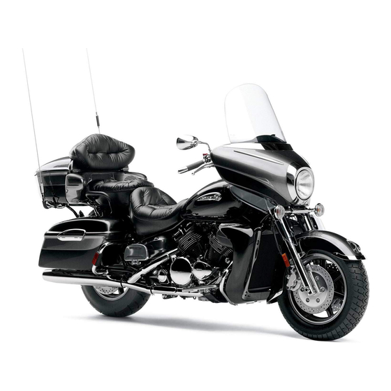
Description
11
ESU10262
1,2,3 4 9 10,11,12 13 14
15
16
17
5,6 7 8
1. Battery
2. Main fuse
3. Air filter
4. Oil filler cap
5. Fuse box
6. Coolant reservoir
7. Passenger grip warmer switch
8. Passenger grip
9. Backrest
10. Storage compartment
11. Storage pouch
12. Tool kit
13. Tail/brake light
14. Tow hitch (For RUSSIA) / tow hitch bracket
(For EUROPE)
15. Slide rail suspension
16. Drive track
17. V-belt holder
U8JVS1E0.book Page 11 Tuesday, May 10, 2016 9:05 AM
Page: 19
Description
12
TIP
The snowmobile you have purchased may differ slightly from those shown in the figures of
this manual.
Design and specifications are subjected to change without notice.
1 2 3 5
4 6
7
8
9
10
1. Brake lever
2. Parking brake lever
3. Grip warmer adjusting switch
4. Thumb warmer adjusting switch
5. Engine stop switch
6. Throttle lever
7. Main switch
8. Shift lever
9. Auxiliary DC jack
10. Headlight beam switch
U8JVS1E0.book Page 12 Tuesday, May 10, 2016 9:05 AM
Page: 20
Control functions
13
ESU10293
Main switch
The main switch controls the ignition and
lighting systems. The various positions are
described below.
Off
The ignition circuit is switched off.
The key can be removed only in this position.
On
The ignition circuit is switched on.
Start
The starting circuit is switched on.
The starter motor cranks the engine.
NOTICE: Release the switch immediately
after the engine starts.[ECS00022]
TIP
The headlights and taillight come on after the
engine is started.
ESU10313
Throttle lever
Once the engine is running cleanly, squeez-
ing the throttle lever will increase the engine
speed and cause engagement of the drive
train. Regulate the speed of the snowmobile
by varying the throttle position. Because the
throttle is spring-loaded, the snowmobile will
decelerate, and the engine will return to idle
when it is released.
ESU13243
Throttle override system
(T.O.R.S.)
WARNING
EWS00042
If the T.O.R.S. is activated, make sure that
the cause of the malfunction has been
corrected and that the engine can be op-
erated without a problem before restarting
the engine. Continuing to operate with a
malfunction could cause loss of control or
damage.
If the throttle valves or throttle cable malfunc-
tions during operation, the T.O.R.S. will be
activated when the throttle lever is released.
The T.O.R.S. is designed to override the fuel
injection and limit the engine speed to less
than the clutch engagement speed if the
throttle valves fail to return to the idle position
when the throttle lever is released. (See page
90 for the clutch engagement speed.)
1. Off
2. On
3. Start
1 3
2
1. Throttle lever
U8JVS1E0.book Page 13 Tuesday, May 10, 2016 9:05 AM
Page: 21
Control functions
14
TIP
If the T.O.R.S. is activated, the warning light
and engine trouble warning indicator flash,
and the two-digit code “84” displays in the
meter display. If this occurs, have a Yamaha
dealer check the system as soon as possible.
ESU14841
Multi-function meter unit
The multi-function meter unit is equipped
with the following:
a digital speedometer
a tachometer
an odometer
two tripmeters
a fuel reserve tripmeter
an oil change tripmeter
a clock
a drive mode display
warning indicators
a warning light
a low coolant temperature indicator light
a high beam indicator light
a fuel meter
a grip/thumb warmer level indicator
a display brightness control function
When the key is turned to the on position, the
tachometer needle makes one sweep, and
the low coolant temperature indicator light,
the warning light, and all segments of the me-
ter unit display come on and go off.
The grip warmer level is initially displayed for
5 seconds, then the display switches to the
fuel meter.
TIP
To switch the speedometer, odometer, and
tripmeter displays between kilometers and
miles, select the odometer mode “ODO”, and
then push the “SELECT” button for at least
10 seconds while the snowmobile is stopped.
Idling Riding
Malfunc-
tion
Throttle
lever
Released Squeezed Released
Throttle
valve
Closed Open Open
T.O.R.S.
Engine
runs
properly.
Engine
runs
properly.
T.O.R.S.
will be
activated.
1. Warning light “ ”
2. Engine trouble warning indicator “ ”
3. Two-digit code “84”
1. “MODE” button
2. “RESET” button
3. “SELECT” button
4. Tachometer
5. Warning indicators
6. Clock
7. Low coolant temperature indicator
light “ ”
8. High beam indicator light “ ”
9. Warning light “ ”
10. Electric power steering warning indicator
“EPS”
11. Drive mode display
12. Meter display
12
10
7
9
2 3 4 5 6
1
8
11
U8JVS1E0.book Page 14 Tuesday, May 10, 2016 9:05 AM
Page: 22
Control functions
15
Odometer and tripmeter modes
Odometer shows the total distance that the
vehicle has run.
Tripmeter A and tripmeter B show the dis-
tance traveled since they last reset.
Fuel reserve tripmeter shows the distance
traveled since the fuel level warning indicator
and warning light came on.
Pushing the “SELECT” button switches the
display between the odometer mode “ODO”
and the tripmeter modes “TRIP A” and “TRIP
B” in the following order:
ODO → TRIP A → TRIP B → ODO
If the fuel level warning indicator and warning
light come on (see page 18), the odometer
display will automatically change to the fuel
reserve tripmeter mode “TRIP F” and start
counting the distance traveled from that
point. In that case, push the “SELECT” but-
ton to switch the display between the various
tripmeter and odometer modes in the follow-
ing order:
TRIP F → ODO → TRIP A → TRIP B → TRIP F
To reset a tripmeter, select it by pushing the
“SELECT” button, and then push the “RE-
SET” button for at least 1 second. If you do
not reset the fuel reserve tripmeter manually,
it will reset itself automatically, and the dis-
play will return to the prior mode after the
snowmobile has been refueled and traveled 5
km (3 mi).
TIP
Odometer resets and continues counting
when it reaches 99999 while riding. How-
ever on the 10th time, the odometer will
lock at 99999.
Tripmeter A and tripmeter B reset and con-
tinue counting when they reach 999.9 while
riding.
Oil change tripmeter
Oil change tripmeter shows the distance trav-
eled since the periodic oil change interval
was reached.
When the periodic oil change interval is
reached at the initial 800 km (500 mi), then at
every 4000 km (2500 mi) thereafter, the oil
change tripmeter and “OIL” flash alternately
in the odometer display, and the tripmeter
starts counting the distance traveled from
that point. When this occurs, change the en-
gine oil as soon as possible. (See page 59 for
the oil change procedure.)
TIP
The oil change tripmeter will flash only
when the snowmobile is stopped.
To return to the previous display mode,
push the “SELECT” button. To display the
oil change tripmeter again, turn the key to
the off position, then back to the on posi-
tion.
1. Odometer/tripmeter/fuel reserve tripmeter
1
U8JVS1E0.book Page 15 Tuesday, May 10, 2016 9:05 AM
Page: 23
Control functions
16
After changing the engine oil, reset the oil
change tripmeter as follows.
To reset the oil change tripmeter (when the
engine oil was changed after the oil change
tripmeter appeared)
1. To display the oil change tripmeter, turn
the key to the on position.
2. Push the “RESET” button for at least 1
second while the oil change tripmeter
and “OIL” are flashing alternately in the
odometer display. The distance traveled
since the last oil change and “OIL” will
flash alternately in the odometer display.
3. Push the “RESET” button for approxi-
mately 3 seconds. “00000” and “OIL” will
flash alternately in the odometer display
3 times, and then the display will return
to the previous display mode.
If the engine oil is changed before the oil
change tripmeter appears in the display (i.e.,
before the periodic oil change interval has
been reached), the tripmeter must be reset
after the oil change for the next periodic oil
change to be indicated at the correct time.
In that case, reset the oil change tripmeter as
follows.
To reset the oil change tripmeter (when the
engine oil was changed before the oil change
tripmeter appeared)
1. Push the “SELECT” button until “ODO”
is displayed, and then push the “RESET”
button for at least 1 second. The dis-
tance traveled since the last oil change
and “OIL” will flash alternately in the
odometer display.
2. Push the “RESET” button for approxi-
mately 3 seconds. “00000” and “OIL” will
flash alternately in the odometer display
3 times, and then the display will return
to the previous display mode.
Clock
The clock uses a 12-hour time system.
To set the clock
1. Turn the key to the on position.
2. Push the “SELECT” button and “RESET”
button simultaneously until the hour dig-
its start flashing.
3. Push the “RESET” button to change the
hour setting, and then push the “SE-
LECT” button. The minute digits will start
flashing.
4. Push the “RESET” button to change the
minute setting, and then push the “SE-
LECT” button. The clock starts when the
“SELECT” button is released.
TIP
The clock must be set again when the battery
is disconnected.
1. Clock
F
E
1
U8JVS1E0.book Page 16 Tuesday, May 10, 2016 9:05 AM
Page: 24
Control functions
17
Drive mode display
This display indicates which drive mode has
been selected: “S”, “T” or “E”. For more de-
tails on the modes and on how to select
them, refer to page 17.
Display brightness control
This function allows you to adjust the bright-
ness of the meter unit display to suit the out-
door lighting conditions.
To adjust the display brightness
1. Turn the key to the off position.
2. Push and hold down the “SELECT” but-
ton.
3. Turn the key to the on position, and then,
after 5 seconds, release the “SELECT”
button.
4. Push the “RESET” button to select the
desired display brightness level, and
then push the “SELECT” button. The dis-
play returns to the previous display mo-
de.
ESU14960
D-mode (drive mode)
D-mode is an electronically controlled engine
performance system with three mode selec-
tions: “S”, “T”, and “E”.
Sport mode “S”
This mode offers a sportier engine response
compared to the other modes.
Touring mode “T”
This mode allows the rider to enjoy smooth
drivability from the low-speed range to the
high-speed range.
Entry mode “E”
This mode offers a reduction of engine power
compared to the other modes and is suitable
for the entry-level rider.
Push the “MODE” button to switch between
modes.
WARNING
EWS00840
Do not change the D-mode while the vehi-
cle is moving.
1. Drive mode display
1. Display brightness level
1
1
1. “MODE” button
1
U8JVS1E0.book Page 17 Tuesday, May 10, 2016 9:05 AM
Page: 25
Control functions
18
TIP
The throttle lever must be completely
closed in order to change the drive mode.
Before using D-mode, make sure you un-
derstand its operation along with the oper-
ation of the “MODE” button.
ESU10412
High beam indicator light “ ”
The high beam indicator light comes on when
the high beams of the headlights are
switched on. (See page 22 for headlight
beam switch operation.)
ESU10474
Low coolant temperature indi-
cator light “ ”
The low coolant temperature indicator light
comes on when the coolant temperature is
low and informs the rider that the snowmobile
should be warmed up. After the engine is
started, warm it up until the indicator light
goes off.
The snowmobile can be operated normally
after the indicator light goes off.
TIP
Drive the snowmobile at low speeds when
the low coolant temperature indicator light is
on. If the engine speed is too high, maximum
engine speed is reduced to protect the en-
gine.
ESU10428
Fuel meter and grip/thumb
warmer level indicator
The fuel meter and grip/thumb warmer level
indicator have eight segments which show
the amount of fuel remaining in the fuel tank,
the grip warmer level, or the thumb warmer
level.
1. High beam indicator light “ ”
1. Low coolant temperature indicator
light “ ”
1. Fuel meter and grip/thumb warmer level in-
dicator
U8JVS1E0.book Page 18 Tuesday, May 10, 2016 9:05 AM
Page: 26
Control functions
19
Fuel meter
The display segments of the fuel meter disap-
pear towards “E” (Empty) as the fuel level de-
creases. When only one segment is left near
“E”, the fuel level warning indicator and the
warning light come on.
If the fuel level warning indicator and the
warning light come on, refuel as soon as pos-
sible.
TIP
The snowmobile must be stopped on a level
surface to obtain an accurate fuel meter
reading, since the reading changes accord-
ing to the movement and inclination of the
snowmobile.
Grip/thumb warmer level indicator
When the grip warmer adjusting switch is
pressed, the grip warmer indicator comes on
and the display switches to the grip warmer
level.
When the thumb warmer adjusting switch is
pressed, the thumb warmer indicator comes
on and the display switches to the thumb
warmer level.
See “Grip/thumb warmer adjusting switch”
on page 22 for detailed information.
TIP
The grip/thumb warmer level is displayed
for 5 seconds after releasing the
grip/thumb warmer adjusting switch, then
the display switches to the fuel meter.
The top segment of the grip/thumb warmer
level indicator flashes once when the
grip/thumb warmer adjustment reaches
1. Fuel level warning indicator “ ”
2. Warning light “ ”
1. Grip warmer indicator “ ”
2. Thumb warmer indicator “ ”
1. Grip warmer adjusting switch
1. Thumb warmer adjusting switch
1
U8JVS1E0.book Page 19 Tuesday, May 10, 2016 9:05 AM
Page: 27
Control functions
20
the maximum level. The bottom segment of
the grip/thumb warmer level indicator
flashes once when the grip/thumb warmer
adjustment reaches the minimum level.
When the engine is started, the grip/thumb
warmer levels are set to the levels selected
when the engine was last stopped.
ESU13253
Fuel level warning indicator “ ”
The fuel level warning indicator and the warn-
ing light come on when the fuel level is low.
(See page 18 for details.)
The fuel level warning indicator, the warning
light, the fuel meter indicator, and all seg-
ments of the fuel meter start to flash when a
malfunctioning sensor, disconnected cou-
pler, broken lead, or short circuit is detected
by the self-diagnosis device of the snowmo-
bile to warn the rider of any of the above
problems.
If this occurs, have a Yamaha dealer inspect
the snowmobile as soon as possible.
ESU13992
Oil level/pressure warning
indicator “ ”
The oil level/pressure warning indicator has
two functions. The warning indicator comes
on when the engine oil level is low and when
the engine oil pressure is low. The functions
are explained in the following sections.
Oil level warning
The warning indicator and the warning light
come on when the engine oil level is low.
If the warning indicator and the warning light
come on, place the snowmobile on a level
surface and allow it to idle for one minute.
If the warning indicator and the warning light
go off, the engine oil level is sufficient, how-
ever it is getting low. Add engine oil as soon
as possible.
If the warning indicator and the warning light
do not go off, check the engine oil level in the
oil tank (see page 59 for engine oil level
checking procedures), and add engine oil if
necessary.
If the warning indicator and the warning light
still remain on, have a Yamaha dealer check
the snowmobile.
1. Fuel level warning indicator “ ”
2. Warning light “ ”
3. Fuel meter
4. Fuel meter indicator “ ”
3 1 2
4
1. Oil level/pressure warning indicator “ ”
2. Warning light “ ”
U8JVS1E0.book Page 20 Tuesday, May 10, 2016 9:05 AM
Page: 28
Control functions
21
Oil pressure warning
The warning indicator comes on and “OP-
LO” (oil pressure low) appears in the odome-
ter display if the engine oil pressure is low
when the engine is started. At the same time,
the engine speed is limited to less than the
clutch engagement speed until the warning
indicator goes off.
If the engine oil pressure remains low for one
minute, the engine stops. If this occurs, have
a Yamaha dealer check the snowmobile.
TIP
If there is no engine oil in the oil passages
when the engine is started, such as after the
engine oil is changed, the warning indicator
may come on and “OP-LO” may appear in
the odometer display for a few seconds until
the oil circulates through the engine. The
snowmobile can be operated normally after
the warning indicator goes off.
ESU10514
Coolant temperature warning
indicator “ ”
If the engine overheats, the coolant tempera-
ture warning indicator and the warning light
come on. When this occurs, stop the engine
immediately and allow the engine to cool
down, and then check the coolant level in the
coolant reservoir. (See page 63 for checking
procedures.)
NOTICE
ECS00042
Do not continue to operate the engine if it
is overheating.
ESU13813
Electric power steering warn-
ing indicator “EPS”
The electric power steering warning indicator
comes on when the key is turned to the on
position, and then goes off once the engine is
started. If the warning indicator remains on or
comes on after the engine is started, the EPS
system may not be working correctly. When
this occurs, have a Yamaha dealer check the
EPS system.
1. Oil level/pressure warning indicator “ ”
2. “OP-LO” (oil pressure low)
1
2
1. Coolant temperature warning
indicator “ ”
2. Warning light “ ”
1. Electric power steering warning indicator
“EPS”
U8JVS1E0.book Page 21 Tuesday, May 10, 2016 9:05 AM
Page: 29
Control functions
22
TIP
If the steering load is too heavy (i.e., exces-
sive steering use when the snowmobile is
traveling at a slow speed), the power assist is
reduced to protect the EPS motor from over-
heating.
ESU13366
Self-diagnosis device
This model is equipped with a self-diagnosis
device for various electrical circuits.
If a problem is detected in any of those cir-
cuits, the warning light and the engine trouble
warning indicator flash, and an error code
displays in the meter display. Note the error
code, and then have a Yamaha dealer in-
spect the snowmobile as soon as possible.
NOTICE: Do not continue to operate the
engine longer than necessary if there is an
error code to avoid possible engine dam-
age.[ECS00821]
ESU10532
Engine stop switch “ ”
The engine stop switch is used to stop the
engine in an emergency. Simply push the
stop switch to stop the engine. To start the
engine, pull the stop switch and proceed with
starting the engine. (See page 38 for engine
starting procedures.)
During the first few rides, practice using the
stop switch so that you can react quickly in
an emergency.
ESU10662
Headlight beam switch
“LIGHTS”
Push the headlight beam switch to change
the headlight to high beam “HI” or to low
beam “LO”.
ESU12655
Grip/thumb warmer adjusting
switch
The grip warmer adjusting switch and the
thumb warmer adjusting switch control the
electrically heated handlebar grips and throt-
tle lever respectively.
1. Warning light “ ”
2. Engine trouble warning indicator “ ”
3. Error code display
3 1
2
1. Engine stop switch “ ”
1. Headlight beam switch “LIGHTS”
2. High beam “HI”
3. Low beam “LO”
U8JVS1E0.book Page 22 Tuesday, May 10, 2016 9:05 AM
Page: 30
Control functions
23
To raise the temperature
To raise the temperature, press the respec-
tive switch to “HI”.
To lower the temperature
To lower the temperature, press the respec-
tive switch to “LO”.
See “Fuel meter and grip/thumb warmer level
indicator” on page 18 for detailed informa-
tion.
ESU10697
Auxiliary DC jack
The auxiliary DC jack is located in the front
panel and can be used for accessories.
TIP
The auxiliary DC jack can only be used if the
engine is running.
To use the auxiliary DC jack
1. Start the engine.
2. Open the auxiliary DC jack cap, and then
insert the accessory power plug into the
jack.
3. After using the auxiliary DC jack, be sure
to remove the accessory power plug
from the jack and to close the auxiliary
DC jack cap.
NOTICE
ECS00123
To avoid circuit overload and a possible
fuse blowing, do not use accessories re-
quiring more than the maximum rated
capacity for the auxiliary DC jack. (See
page 80 for the specified fuse amper-
age.)
Do not use an automotive cigarette
lighter or other accessory with a plug
that gets hot because the jack can be
damaged.
ESU10552
Brake lever
The snowmobile is stopped by braking the
entire drive system.
Squeeze the brake lever towards the handle-
bar grip to stop the snowmobile.
1. Grip warmer adjusting switch
1. Thumb warmer adjusting switch
1
1. Auxiliary DC jack cap
2. Auxiliary DC jack
Maximum rated capacity:
DC 12 V, 2.5 A (30 W)
1
2
U8JVS1E0.book Page 23 Tuesday, May 10, 2016 9:05 AM
Page: 31
Control functions
24
TIP
When the brake lever is squeezed, the brake
light comes on.
NOTICE
ECS00061
Make sure that the brake lever end does
not project out over the handlebar end.
This will help prevent brake lever damage
when the snowmobile is placed on its side
for service.
ESU10582
Parking brake lever
When parking the snowmobile or starting the
engine, apply the parking brake by moving
the parking brake lever to the left.
To release the parking brake, move the park-
ing brake lever to the right.
ESU10594
Shift lever
The shift lever is used to put the snowmobile
into forward or reverse. After coming to a
complete stop, pull the shift lever out, slide it
to “FWD” or to “REV” until it stops, and then
release it.
1. Brake lever
1. Parking brake lever
1. Shift lever
1. Pull out.
2. Slide to “FWD” (forward).
3. Release.
1
1
2 3
U8JVS1E0.book Page 24 Tuesday, May 10, 2016 9:05 AM
Page: 32
Control functions
25
NOTICE
ECS00073
Do not use the shift lever while the snow-
mobile is moving, otherwise the drive train
could be damaged.
ESU13315
Drive guard
WARNING
EWS00403
Coming in contact with the rotating V-
belt or clutch parts can cause severe in-
jury or death. Never run the engine with
the drive guard removed.
Make sure that the drive guard is in-
stalled securely before operating the
snowmobile to protect against severe
injury or death from a broken V-belt or
other part should it come off the snow-
mobile while it is in operation.
NOTICE
ECS00931
Never run the engine with the V-belt re-
moved. Clutch components can be
damaged.
Be careful not to scratch the windshield
when removing or installing the drive
guard.
The drive guard is designed to protect the V-
belt clutch and V-belt in case parts break or
come loose.
The drive guard is located behind the left side
cover. (See page 51 for removal procedures.)
To remove the drive guard
1. Pull out the drive guard locking pin from
the drive guard rear holder.
2. Lift up the rear of the drive guard as
shown, and then pull the guard rearward
to remove it.
To install the drive guard
1. Fit the front slots in the drive guard over
the projections on the drive guard front
holder.
1. Pull out.
2. Slide to “REV” (reverse).
3. Release.
3
2
1
1. Drive guard
2. Drive guard locking pin
2
1
U8JVS1E0.book Page 25 Tuesday, May 10, 2016 9:05 AM
Page: 33
Control functions
26
2. Align the slots in the rear of the drive
guard with the projections on the drive
guard rear holder, and then insert the
drive guard locking pin into the holder as
shown.
ESU10762
V-belt holders
Keep a spare V-belt for emergency use by
placing it into the V-belt holders provided.
NOTICE
ECS00181
Make sure that the V-belt is installed se-
curely in the holders.
ESU13303
Passenger grips
The passenger grips can be installed in three
different positions to suit the passenger’s
preference.
To change the passenger grip posi-
tion
1. Remove the passenger grip adjusting
knob by turning it counterclockwise.
2. Move the passenger grip to the desired
position.
3. Install the adjusting knob by turning it
clockwise.
1. Drive guard
1. Drive guard
2. Drive guard locking pin
1
1
2
1. V-belt holder
1. Passenger grip
2. Passenger grip adjusting knob
1
2
1
U8JVS1E0.book Page 26 Tuesday, May 10, 2016 9:05 AM
Page: 34
Control functions
27
WARNING
EWS00781
Make sure that the passenger grip adjust-
ing knobs are securely tightened after
changing the positions of the passenger
grips.
ESU10682
Passenger grip warmer switch
The passenger grip warmer switch controls
the electrically heated passenger grips.
ESU14611
Passenger footrests
The passenger footrests can be installed in
three different positions to suit the passen-
ger’s preference.
To change the position of a footrest, remove
the screws, place the footrest in the desired
position, and then install and tighten the
screws.
NOTICE
ECS00132
Make sure that the screws are tightened
securely after changing the position of
the footrests.
Do not overtighten the screws, other-
wise the footrest may be damaged.
ESU14131
Backrest
WARNING
EWS00132
Do not sit on the backrest. Otherwise, you
could lose your balance, fall, and be in-
jured.
The angle and position of the backrest are
adjustable.
To adjust the backrest angle
Turn the backrest adjusting knob until the
backrest reaches the desired angle.
1. Passenger grip warmer switch
2. Off
3. “HI” (high)
4. “LO” (low)
H
I
LO
1
3
2
4
1. Footrest
2. Screw
2
1
U8JVS1E0.book Page 27 Tuesday, May 10, 2016 9:05 AM
Page: 35
Control functions
28
To adjust the backrest position
Pull the backrest adjusting lever upward, and
then move the backrest to the desired posi-
tion.
When riding without a passenger, the back-
rest can be moved to the forward-most posi-
tion, and its angle can be adjusted to suit the
operator’s preference as shown.
ESU14700
Storage compartment
This snowmobile is equipped with a storage
compartment, which includes a storage
pouch.
Storage compartment
NOTICE
ECS00901
The bottom of the storage compartment
may be hot during or immediately after op-
erating the snowmobile. It can cause
burns if it becomes extremely hot. Further-
more, heat in the storage compartment
can affect the quality of food items, and
deform and discolor plastic items.
The storage compartment is located behind
the seat. Use the storage compartment to
store the storage pouch, spare parts, or other
small items.
To open the storage compartment
Unhook the storage compartment latches
and open the storage compartment lid.
1. Backrest
2. Backrest adjusting knob
1. Backrest
2. Backrest adjusting lever
2
1
2
1
U8JVS1E0.book Page 28 Tuesday, May 10, 2016 9:05 AM
Page: 36
Control functions
29
TIP
Before opening the storage compartment lid,
move the backrest forward so that the lid can
be opened. (See page 27 for backrest adjust-
ment procedures.)
To close the storage compartment
Close the storage compartment lid, and then
hook the storage compartment latches.
Storage pouch
The storage pouch is located inside the stor-
age compartment. Use the storage pouch to
store the tool kit, manuals, spare parts, or
other small items.
NOTICE
ECS00782
Before starting the engine, make sure that
the tool kit is securely fastened and that
the storage pouch zipper is completely
closed.
ESU13203
Tow hitch (For RUSSIA) and tow
hitch bracket (For EUROPE)
NOTICE
ECS00242
To prevent premature wear of the V-belt,
avoid traveling under 10 km/h (6 mi/h)
when towing for long distances or long pe-
riods of time.
Tow hitch (For RUSSIA)
Use the tow hitch within the specified weight
limits.
1. Storage compartment latch
2. Storage compartment lid
1. Storage compartment
Maximum load limit:
20 kg (44 lbs)
1
2
1
1. Storage pouch
1. Tow hitch
1
1
U8JVS1E0.book Page 29 Tuesday, May 10, 2016 9:05 AM
Page: 37
Control functions
30
Tow hitch bracket (For EUROPE)
This snowmobile is equipped with a tow hitch
bracket that is used to install a tow hitch.
Use the tow hitch bracket within the specified
weight limits.
TIP
A tow hitch is available at a Yamaha dealer.
ESU10619
Fuel
WARNING
EWS00072
Gasoline and gasoline vapors are ex-
tremely flammable. To avoid fires and ex-
plosions and to reduce the risk of injury
when refueling, follow these instructions.
Make sure there is sufficient gasoline in the
tank.
1. Before refueling, turn off the engine and
be sure that nobody is on the snowmo-
bile. Never refuel while smoking, or while
in the vicinity of sparks, open flames, or
other sources of ignition such as the pilot
lights of water heaters and clothes dry-
ers.
2. Do not overfill the fuel tank. Stop filling
when the fuel reaches the bottom of the
filler tube. Because fuel expands when it
heats up, heat from the engine or the sun
can cause fuel to spill out of the fuel tank.
3. Wipe up any spilled fuel immediately.
4. Be sure the fuel tank cap is closed se-
curely by turning it clockwise.
Tow weight limit:
120 kgf (264 lbf)
Vertical weight limit:
15 kgf (33 lbf)
1. Tow hitch bracket
Tow weight limit:
120 kgf (264 lbf)
Vertical weight limit:
15 kgf (33 lbf)
1
1. Filler tube
2. Maximum fuel level
U8JVS1E0.book Page 30 Tuesday, May 10, 2016 9:05 AM
Page: 38
Control functions
31
WARNING
EWS00681
Gasoline is poisonous and can cause inju-
ry or death. Handle gasoline with care.
Never siphon gasoline by mouth. If you
should swallow some gasoline or inhale a
lot of gasoline vapor, or get some gasoline
in your eyes, see your doctor immediately.
If gasoline spills on your skin, wash with
soap and water. If gasoline spills on your
clothing, change your clothes.
Your Yamaha engine has been designed to
use unleaded gasoline with a research oc-
tane number of 95 or higher. (For Russia, reg-
ular unleaded gasoline with a pump octane
number [(R+M)/2] of 86 or higher, or a re-
search octane number of 91 or higher.)
NOTICE
ECS00095
Make sure that snow or ice does not en-
ter the fuel tank when refueling.
The fuel tank should be filled with the
recommended gasoline. The use of oth-
er gasoline will cause severe damage to
internal engine parts, such as the valves
and piston rings, as well as to the ex-
haust system.
ESU14880
Suspension
The suspension can be adjusted to suit rider
preference. Softer settings, for example, may
provide greater rider comfort, while harder
settings may allow more precise handling
and control over certain types of terrain or
riding conditions.
If you are not familiar with suspension adjust-
ments, have a Yamaha dealer make these
adjustments.
WARNING
EWS00152
Read and understand the following infor-
mation before handling shock absorbers
that contain highly pressurized nitrogen
gas.
Do not tamper with or attempt to open
the cylinder assemblies.
Do not subject the shock absorbers to
an open flame or other high heat source.
This may cause the unit to explode due
to excessive gas pressure.
Do not deform or damage the cylinders
in any way. Cylinder damage will result
in poor damping performance.
Do not dispose of a damaged or worn
out shock absorber yourself. Take the
shock absorber to a Yamaha dealer for
any service.
TIP
A special wrench can be obtained at a
Yamaha dealer.
Recommended fuel:
Min 91 RON UNLEADED GASOLINE
ONLY (RUS)
Min 95 RON UNLEADED GASOLINE
ONLY (FIN, SWE)
Fuel tank capacity:
34.6 L (9.13 US gal, 7.61 Imp.gal)
U8JVS1E0.book Page 31 Tuesday, May 10, 2016 9:05 AM
Page: 39
Control functions
32
ESU10895
Adjusting the spring preload of the
front shock absorbers
WARNING
EWS00721
The spring preload of the left and right
shock absorbers must be adjusted to the
same setting. Uneven settings can cause
poor handling and loss of stability.
The spring preload can be adjusted by turn-
ing the adjusting nuts.
Adjust the spring preload as follows.
1. Loosen the locknut.
2. To increase the spring preload and
thereby harden the suspension, turn the
adjusting nut in direction (a). To decrease
the spring preload and thereby soften
the suspension, turn the adjusting nut in
direction (b).
TIP
The spring preload setting is determined by
measuring distance A, shown in the illustra-
tion. The longer distance A is, the higher the
spring preload; the shorter distance A is, the
lower the spring preload.
3. Tighten the locknut to the specified
torque. NOTICE: Always tighten the
locknut against the adjusting nut, and
then tighten the locknut to the speci-
fied torque.[ECS00861]
ESU13137
Adjusting the spring preload of the
center shock absorber and the rear
torsion springs
The spring preload can be adjusted by turn-
ing the adjusting nut on the center shock ab-
sorber and the adjusters on the rear torsion
springs. Adjust the spring preload as follows.
Center shock absorber
1. Loosen the locknut.
2. To increase the spring preload and
thereby harden the suspension, turn the
adjusting nut in direction (a). To decrease
the spring preload and thereby soften
the suspension, turn the adjusting nut in
direction (b).
1. Locknut
2. Distance A
3. Spring preload adjusting nut
(a)
(b)
1
3
2
Spring preload setting*:
Minimum (soft):
160.0 mm (6.30 in)
Standard:
163.0 mm (6.42 in)
Maximum (hard):
173.0 mm (6.81 in)
* Distance A changes 1.5 mm (0.06 in)
with each full turn of the adjusting
nut.
Tightening torque:
Locknut:
30 N·m (3.0 kgf·m, 22 lb·ft)
U8JVS1E0.book Page 32 Tuesday, May 10, 2016 9:05 AM
Page: 40
Control functions
33
TIP
The spring preload setting is determined by
measuring distance A, shown in the illustra-
tion. The longer distance A is, the higher the
spring preload; the shorter distance A is, the
lower the spring preload.
3. Tighten the locknut to the specified
torque. NOTICE: Always tighten the
locknut against the adjusting nut, and
then tighten the locknut to the speci-
fied torque.[ECS00861]
Rear torsion springs
WARNING
EWS00751
The left and right spring preloads must be
adjusted to the same setting. Uneven set-
tings can cause poor handling and loss of
stability.
To increase the spring preload and thereby
harden the suspension, turn the adjuster in
direction (a). To decrease the spring preload
and thereby soften the suspension, turn the
adjuster in direction (b).
ESU11036
Adjusting the control rods
WARNING
EWS00771
The left and right adjusting nuts must be
set to the same position. Uneven settings
can cause poor handling and loss of sta-
bility.
The weight transfer can be adjusted by turn-
ing the adjusting nuts on the control rods.
1. Spring preload adjusting nut
2. Distance A
3. Locknut
Spring preload setting*:
Minimum (soft):
111.0 mm (4.37 in)
Standard:
112.0 mm (4.41 in)
Maximum (hard):
122.0 mm (4.80 in)
* Distance A changes 1.5 mm (0.06 in)
with each full turn of the adjusting
nut.
Tightening torque:
Locknut:
42 N·m (4.2 kgf·m, 30 lb·ft)
(a)
(b)
2
1
3
1. Spring preload adjuster
Spring preload setting:
Minimum (soft):
S
Standard:
M
Maximum (hard):
H
S
M
(a)
(b)
1
U8JVS1E0.book Page 33 Tuesday, May 10, 2016 9:05 AM
Page: 41
Control functions
34
1. Loosen the locknut while holding the ad-
justing nut.
2. To increase weight transfer, turn the ad-
justing nut in direction (a), and to de-
crease weight transfer, turn it in direction
(b). WARNING! Never adjust the con-
trol rods beyond the maximum set-
ting, indicated by red paint; otherwise,
they could be damaged, which could
lead to an accident or injury. [EWS00174]
3. Tighten the locknut while holding the ad-
justing nut in place. NOTICE: Always
tighten the locknut against the adjust-
ing nut, and then tighten the locknut to
the specified torque.[ECS00861]
ESU13114
Adjusting the spring preload of the
sliding frame extension
WARNING
EWS00751
The left and right spring preloads must be
adjusted to the same setting. Uneven set-
tings can cause poor handling and loss of
stability.
The spring preload of the sliding frame exten-
sion can be adjusted by turning the adjusting
nuts.
To increase the spring preload, turn the ad-
justing nut in direction (a). To decrease the
spring preload, turn the adjusting nut in direc-
tion (b).
1. Locknut
2. Control rod adjusting nut
1
2
(a)
(b)
1. Locknut
2. Control rod adjusting nut
3. Standard position
4. Adjustable range
5. Red paint area
Locknut tightening torque:
25 N·m (2.5 kgf·m, 18 lb·ft)
1
5
2
3
4
U8JVS1E0.book Page 34 Tuesday, May 10, 2016 9:05 AM
Page: 42
Control functions
35
TIP
The spring preload setting is determined by
measuring distance A, shown in the illustra-
tion. The longer distance A is, the higher the
spring preload; the shorter distance A is, the
lower the spring preload.
1. Spring preload adjusting nut
2. Distance A
Spring preload setting*:
Minimum (soft):
16 mm (0.63 in)
Standard:
16 mm (0.63 in)
Maximum (hard):
18 mm (0.71 in)
* Distance A changes 1.25 mm (0.05 in)
with each full turn of the adjusting
nut.
(a)
(b)
1
2
U8JVS1E0.book Page 35 Tuesday, May 10, 2016 9:05 AM
Page: 43
Pre-operation checks
36
ESU11072
Inspect your vehicle each time you use it to make sure the vehicle is in safe operating condi-
tion. Always follow the inspection and maintenance procedures and schedules described in
the Owner’s Manual.
WARNING
EWS00192
Failure to inspect or maintain the vehicle properly increases the possibility of an acci-
dent or equipment damage. Do not operate the vehicle if you find any problem. If a prob-
lem cannot be corrected by the procedures provided in this manual, have the vehicle
inspected by a Yamaha dealer.
ESU11082
Pre-operation check list
ITEM CHECKS PAGE
Fuel
• Check fuel level.
• Refuel if necessary.
• Check fuel line for leakage.
30
Engine oil
• Check oil level in engine.
• If necessary, add recommended oil to specified
level.
• Check vehicle for oil leakage.
59
Coolant
• Check coolant level.
• Add if necessary.
63
V-belt
• Check for wear and damage.
• Replace if necessary.
65
Drive guard
• Make sure the drive guard is installed securely.
• Check the drive guard mounts for damage.
25
Brake
• Check operation.
• If soft or spongy, have Yamaha dealer bleed hy-
draulic system.
• Check brake pads for wear.
• Replace if necessary.
• Check fluid level in master cylinder.
• If necessary, add recommended brake fluid to
specified level.
• Check hydraulic system for leakage.
69
Air filter
• Check that there is no snow under the air filter ele-
ment.
• If necessary, brush off the snow.
56
Tool kit and recommended
equipment
• Check for proper placement. 50, 50
Shroud and covers
• Make sure that the shroud and covers are securely
fastened.
51
Skis and ski runners
• Check for wear and damage.
• If necessary, have Yamaha dealer replace skis or
ski runners.
72
U8JVS1E0.book Page 36 Tuesday, May 10, 2016 9:05 AM
Page: 44
Pre-operation checks
37
Drive track
• Check the deflection.
• Adjust if necessary.
• Check for wear and damage.
• If necessary, have a Yamaha dealer replace track.
73
Slide runners
• Check for wear and damage.
• If necessary, have Yamaha dealer replace slide
runners.
73
Steering • Check for excessive free play. 73
Lights, signals and switch-
es
• Check operation.
• Correct if necessary.
22, 22, 77, 78
Throttle lever
• Make sure that operation is smooth and spring
back to its original position when released.
13
Throttle override system
(T.O.R.S.)
• Check the T.O.R.S. for proper operation.
• If system is not functioning properly, have Yamaha
dealer check vehicle.
55
ITEM CHECKS PAGE
U8JVS1E0.book Page 37 Tuesday, May 10, 2016 9:05 AM
Page: 45
Operation
38
ESU13503
Read the Owner’s Manual carefully to be-
come familiar with all controls. If there is a
control or function you do not understand,
ask your Yamaha dealer.
WARNING
EWS00204
Failure to familiarize yourself with the con-
trols can lead to loss of control, which
could cause an accident or injury.
ESU13213
TIP
This model is equipped with:
an engine oil pressure switch to stop the
engine in case an engine oil pressure drop
is detected. To start the engine after this
system has stopped the engine, be sure to
place the snowmobile on a level surface,
and then turn the key in the main switch to
the off position, and then to the on position.
Failing to do so will prevent the engine from
starting even though the engine will crank
when turning the key to the start position. If
the engine does not start or if it stops
again, ask a Yamaha dealer to inspect the
snowmobile.
an engine overheating prevention system,
which prevents overheating when the en-
gine is idling. When the engine has been
idling for 3 minutes or longer and the cool-
ant temperature has risen above 100 °C
(212 °F), the engine automatically stops to
prevent overheating. The engine can be
started after it stops.
ESU11304
Starting the engine
1. Apply the parking brake.
2. Be sure the engine stop switch is in the
run position. The starter motor cannot be
operated when the engine stop switch is
in the off position.
3. Turn the main switch to the start position
and release it when the engine starts.
NOTICE: Release the switch immedi-
ately after the engine starts. If the en-
gine fails to start, release the switch,
wait a few seconds, then try again.
Each attempt should be as short as
possible to preserve the battery. Do
not crank the engine more than 10
seconds on any one attempt. [ECS00332]
1. Run position
2. Off position
1
2
U8JVS1E0.book Page 38 Tuesday, May 10, 2016 9:05 AM
Page: 46
Operation
39
4. Warm up the engine until it runs smooth-
ly.
5. Be sure the low coolant temperature in-
dicator light has gone out before opera-
tion. (See page 18 for detailed
information about the indicator light.)
ESU11311
Break-in
There is never a more important period in the
life of your engine than the period between 0
and 500 km (300 mi). For this reason, you
should read the following material carefully.
Since the engine is brand new, do not put an
excessive load on it for the first 500 km (300
mi). The various parts in the engine wear and
polish themselves to the correct operating
clearances. During this period, prolonged
full-throttle operation or any condition that
might result in engine overheating must be
avoided.
Operating your snowmobile for the
first time
Start the engine and let it idle for 15 minutes.
0–160 km (0–100 mi)
Avoid prolonged operation above 6000 r/min.
160–500 km (100–300 mi)
Avoid prolonged operation above 8000 r/min.
500 km (300 mi) and beyond
The snowmobile can now be operated nor-
mally.
NOTICE
ECS00341
After 800 km (500 mi) of operation, the
engine oil must be changed and the oil
filter cartridge replaced.
If any engine trouble should occur dur-
ing the engine break-in period, immedi-
ately have a Yamaha dealer check the
snowmobile.
ESU12626
Riding your snowmobile
Getting to know your snowmobile
WARNING
EWS00212
To avoid severe injury or death:
Keep both hands on the handlebar dur-
ing operation.
Never put your feet outside the running
boards.
Avoid higher speeds or more difficult
maneuvers until you have become thor-
oughly familiar with your snowmobile
and all of its controls.
A snowmobile is a rider active vehicle, and
your riding position and your balance are the
two basic factors of maneuvering your snow-
mobile.
Riding your snowmobile requires skills ac-
quired through practice over a period of time.
Take the time to learn the basic techniques
well before attempting more difficult maneu-
vers.
Riding your new snowmobile can be a very
enjoyable activity, providing you with hours of
pleasure. However, it is essential to familiar-
ize yourself with the operation of the snow-
mobile to achieve the skill necessary to enjoy
riding safely. Before operating the snowmo-
bile, read this Owner’s Manual completely
and understand the operation of the controls.
1. Start
1
U8JVS1E0.book Page 39 Tuesday, May 10, 2016 9:05 AM
Page: 47
Operation
40
Pay particular attention to the safety informa-
tion on page 9.
Please read all warning and notice labels on
your snowmobile.
Learning to ride your snowmobile
Before you ride, always perform the pre-op-
eration checks listed on page 36. The short
time spent checking the condition of the
snowmobile will be rewarded with added
safety and a more reliable snowmobile. Al-
ways wear the proper clothing for both
warmth and to help protect you from injury if
an accident occurs.
Become familiar with operating your snow-
mobile at low speeds, even if you are an ex-
perienced rider. Do not attempt to operate at
maximum performance until you are totally
familiar with the snowmobile’s handling and
performance characteristics.
The beginning operator should select a large
flat area to become familiar with the snowmo-
bile. Make sure that this area is free of obsta-
cles and other traffic. You should practice
control of the throttle and brake, and master
turning techniques in this area before trying
more difficult terrain.
Set the parking brake and follow the instruc-
tions on page 38 to start the engine. Once the
engine has warmed up, you are ready to be-
gin riding your snowmobile.
To start out and accelerate
1. With the engine idling, release the park-
ing brake.
2. Apply the throttle slowly and smoothly.
The V-belt clutch will engage and you will
start to accelerate. WARNING! Do not
allow anyone to stand behind the
snowmobile when starting the engine.
A broken track, track fittings, or debris
thrown by the track could be danger-
ous to bystanders.[EWS00691]
Braking
WARNING
EWS00221
Many surfaces such as ice and hard-
packed snow require much longer stop-
ping distances. Be alert, plan ahead, and
begin decelerating early.
Improper use of the brake can cause the
drive track to lose traction, reduce con-
trol, and increase the possibility of an
accident.
When slowing down or stopping, release the
throttle and apply the brake gently—not sud-
denly.
Turning
For most snow surfaces, “body English” is
the key to turning.
As you approach a curve, slow down and be-
gin to turn the handlebar in the desired direc-
tion. As you do so, put your weight on the
running board to the inside of the turn and
lean your upper body into the turn.
This procedure should be practiced at low
speeds many times, in a large flat area with
no obstacles. Once you have learned this
technique, you should be able to perform it at
higher speeds or in tighter curves. Lean more
as the turn gets sharper or is made at higher
speeds.
U8JVS1E0.book Page 40 Tuesday, May 10, 2016 9:05 AM
Page: 48
Operation
41
Improper riding techniques such as abrupt
throttle changes, excessive braking, incor-
rect body movements, or too much speed for
the sharpness of the turn may cause the
snowmobile to tip.
If your snowmobile begins to tip while turn-
ing, lean more into the turn to regain balance.
If necessary, gradually let off on the throttle or
steer to the outside of the turn.
Remember:
Avoid higher speeds until you are thoroughly
familiar with the operation of your snowmo-
bile.
Riding uphill
WARNING
EWS00232
Operation on slopes can lead to loss of
control if proper techniques are not used.
Follow these instructions to reduce your
risk of an accident. Do not try steeper or
more difficult inclines until you have devel-
oped your skill on gentle slopes.
You should practice first on gentle slopes. Try
more difficult climbs only after you have de-
veloped your skill. As you approach a hill, ac-
celerate before you start the climb, and then
reduce the throttle to prevent track slippage.
It is also important to keep your weight on the
uphill side at all times. On climbs straight up
the hill, this can be accomplished by leaning
forward and, on steeper inclines, standing on
the running boards and leaning forward over
the handlebar. (Also see “Traversing a
slope”.)
Slow down as you reach the crest of the hill,
and be prepared to react to obstacles, sharp
drops, or other vehicles or people which may
be on the other side. If you are unable to con-
tinue up a hill, do not spin the track. Stop the
engine and set the parking brake. Then pull
the rear of the snowmobile around to point
the snowmobile back down the hill. When the
snowmobile is pointed downhill, mount your
snowmobile from the uphill side. Restart the
engine, release the parking brake, and de-
scend the hill.
Riding downhill
WARNING
EWS00241
Use extra caution when applying the brake
during a descent. Excessive braking will
cause the drive track to lock, causing a
loss of control.
When riding downhill, keep speed to a mini-
mum. It is important to apply just enough
throttle to keep the clutch engaged while de-
scending the hill. This will allow you to use
engine compression to help slow the snow-
mobile, and to keep the snowmobile from
rolling freely down the hill. Also apply the
brake frequently, with light pressure.
U8JVS1E0.book Page 41 Tuesday, May 10, 2016 9:05 AM
Page: 49
Operation
42
Traversing a slope
WARNING
EWS00252
Driving across the face of a slope (“side-
hilling”) can lead to overturn or loss of
control if proper techniques are not used.
Follow these instructions to reduce your
risk of an accident. Do not try steeper or
more difficult inclines until you have devel-
oped your skill on gentle slopes.
Traversing a slope requires you to properly
position your weight to maintain proper ba-
lance. As you travel across the slope, lean
your body to position your weight towards
the uphill side. A recommended riding posi-
tion is to kneel with the knee of your downhill
leg on the seat and the foot of your uphill leg
on the running board. This position will make
it easier for you to shift your body weight as
needed.
Snow and ice are slippery, so be prepared for
the possibility that your snowmobile could
begin to slip sideways on the slope. If this
happens, steer in the direction of the slide if
there are no obstacles in your path. As you
regain proper balance, gradually steer again
in the direction you wish to travel.
If your snowmobile starts to tip, steer down
the hill to regain balance. WARNING! If you
are unable to maintain correct balance,
and your snowmobile is going to tip over,
dismount your snowmobile immediately
on the uphill side to avoid being hit or
caught under the snowmobile as it tips
over.[EWS00262]
Ice or icy surface
WARNING
EWS00271
When you have to operate on ice or icy
surfaces, drive slowly and cautiously.
Avoid accelerating, turning, and braking
rapidly. Steering is minimal and uncon-
trolled spins are an ever-present danger.
Operating on ice or icy surfaces can be very
dangerous. Traction for turning, stopping,
and starting is much less than that on snow.
Hard-packed snow
It can be more difficult to negotiate on hard-
packed snow as both the skis and drive track
do not have as much traction as when the
snowmobile is operated on fresh snow. Avoid
rapid acceleration, turning, and braking.
Operation on surfaces other than
snow or ice
Operation of your snowmobile on surfaces
other than snow or ice should be avoided.
Operation under such conditions will damage
or result in rapid wear of the ski runners, drive
U8JVS1E0.book Page 42 Tuesday, May 10, 2016 9:05 AM
Page: 50
Operation
43
track, slide runners, and drive sprockets. Op-
eration of the snowmobile on the following
surfaces should be avoided at all times:
Dirt
Sand
Rocks
Grass
Bare pavement
Other surfaces that should be avoided for the
sake of drive track and slide runner life are:
Glare ice surfaces
Snow mixed with a lot of dirt and sand
All of the above surfaces have one thing in
common in regard to drive track and slide
runners: little or no lubricating ability. Drive
track and all slide rail systems require lubrica-
tion (snow or water) between the slide run-
ners and the slide metal. In the absence of
lubrication, the slide runners will rapidly wear
and in severe cases, literally melt away, and
the drive track will be subject to damage or
failure.
Also traction aids such as studs, cleats, etc.,
may cause further track damage or failure.
WARNING
EWS00281
Drive track damage or failure could result
in loss of braking ability and snowmobile
control, which could cause an accident.
Always check the drive track for dam-
age or maladjustment before operating
the snowmobile.
Do not operate the snowmobile if you
find damage to the drive track.
NOTICE
ECS00351
Ride on fresh snow frequently. Operating
on ice or hard-packed snow will rapidly
wear the slide runners.
ESU11351
Maximizing drive track life
Recommendations
Track tension
During initial break-in, the new drive track will
tend to stretch quickly as the track settles. Be
sure to correct the track tension and align-
ment frequently. (See page 73 for adjustment
procedures.) A loose track can slip (ratchet),
derail or catch on suspension parts causing
severe damage. Do not overtighten the drive
track, otherwise it may increase the friction
between the track and the slide runners, re-
sulting in the rapid wear of both components.
Also, this may put an excessive load on the
suspension components, resulting in compo-
nent failure.
Marginal snow
The drive track and the slide runners are lu-
bricated and cooled by snow and water. To
prevent the drive track and slide runners from
overheating, avoid sustained high-speed
usage in areas such as icy trails, frozen lakes
and rivers that have minimal snow coverage.
An overheated track will be weakened inter-
nally, which may cause failure or damage.
Off-trail riding
Avoid off-trail riding until there is sufficient
snow coverage. It generally takes several feet
of snow to provide a good overall base to
properly cover debris, such as rocks, logs,
etc. If snow coverage is not sufficient, stay on
trails to avoid impact damage to the drive
track.
Studded track
In general, track life will be shortened when
studs are installed. Drilling stud holes into the
drive track will cut the internal fibers, which
weakens the track. Avoid spinning the drive
track. Studs may catch on an object and pull
out of the track, leaving tears and damage
U8JVS1E0.book Page 43 Tuesday, May 10, 2016 9:05 AM
manualYamaha RS VENTURE TF (2016)

DIC183
E
F
I
S
SF
N
OWNER’S MANUAL
MANUEL DU PROPRIÉTAIRE
USO E MANUTENZIONE
INSTRUKTIONSBOK
OMISTAJAN KÄSIKIRJA
EIERHÅNDBOK
E
F
I
S
SF
N
Les denne håndboken nøye før du tar kjøretøyet i bruk.
Lue tämä käsikirja huolellisesti ennen moottorikelkan käyttöä.
Läs den här instruktionsboken noga innan snöskotern används.
Leggere attentamente questo manuale prima di utilizzare questo veicolo.
Read this manual carefully before operating this vehicle.
Il convient de lire attentivement ce manuel avant la première utilisation du véhicule.