|
|
Ремонт частотных преобразователей SEW-EURODRIVE
 Ремонт частотного преобразователя SEW-EURODRIVE, впрочем, как и ремонт частотников других производителей имеет ряд особенностей в силу своего конструктива. Частотные преобразователи, точнее их начинка делятся на две части:
- Аппаратная часть,
- Программная часть.
Частотники данного производителя не являются исключением из правил, именно поэтому ремонт частотного преобразователя SEW-EURODRIVE имеет точно такой же ряд особенностей, как и у других преобразователей.
Диагностировать ту или иную неисправность помогают коды ошибок частотного преобразователя, которые отображаются на небольшом дисплее, расположенном на лицевой панели привода. Коды ошибок частотного преобразователя SEW-EURODRIVE в зависимости от серии описаны в инструкции, пользователя которые можно скачать с нашего сайта.
Ремонт частотных преобразователей SEW-EURODRIVE в Челеке, как и любых других преобразователей, выпущенных под другими брендами, всегда начинается с аппаратной части, после успешного ремонта аппаратной части наступает очередь программной.
Настройка частотного преобразователя SEW-EURODRIVE также прописана в инструкции завода производителя, для каждой серии частотных преобразователей настройка будет индивидуальной, так как каждая линейка преобразователей решает свои собственные задачи, этим обусловливается широкая номенклатура данного промышленного оборудования.
Ремонт частотных преобразователей SEW-EURODRIVE в сервисном центре
 Компания «Кернел» производит ремонт частотных преобразователей SEW-EURODRIVE в Челеке с 2002 года. За время существования компании наши сотрудники накопили колоссальный опыт в ремонте преобразователей частоты такого известного производителя как SEW-EURODRIVE. Ремонт подобного промышленного оборудования ответственное и сложное занятие, требующие максимальной отдачи, профессионализма и максимально полной материальной базе.
Специалисты нашего сервисного центра максимальное внимание уделяют качеству исполнения ремонта, программирования и настройке промышленных преобразователей частоты, не зависимо от производителя данного промышленного оборудования. Именно поэтому мы смело даем гарантию на все выполненные работы шесть месяцев.
Ремонт частотных преобразователей SEW-EURODRIVE в Челеке производится исключительно с использованием оригинальных запасных частей, на компонентном уровне с применением высокотехнологичного диагностического оборудования, квалифицированным персоналом с инженерным образованием.
В случае выхода из строя преобразователя частоты на вашем производстве либо появились проблемы с приводом, которые вы не можете решить самостоятельно, мы всегда рады вам помочь. Специалисты нашего сервисного центра в минимальные сроки проведут глубокую диагностику с последующим ремонтом частотного преобразователя SEW-EURODRIVE.
Инженеры сервисного центра выполняют качественный ремонт частотных преобразователей SEW-EURODRIVE всех серий, когда-либо выпускаемых компанией.
|
Серии частотных преобразователей SEW-EURODRIVE |
Типы частотных преобразователей SEW-EURODRIVE |
|
MOVITRAC® LTE-B |
MC-LTE-B0004-101-1-00, MC-LTE-B0008-101-1-00, MC-LTE-B0011-101-4-00, MC-LTE-B0004-2B1-1-00, MC-LTE-B0008-2B1-1-00 |
|
MOVITRAC® LTE-B+ |
MC-LTE-B0015-2B1-4-00, MC-LTE-B0022-2B1-4-00, MC-LTE-B0040-2B1-4-00, MC-LTE-B0015-2A3-4-00, MC-LTE-B0015-5A3-1-00 |
|
MOVITRAC® LTP-B |
MC-LTP-B0008-2B1-4-00, LTP-B MC-LTP-B0015-2B1-4-00, LTP-B MC-LTP-B0022-2B1-4-00, LTP-B MC-LTP-B0015-2A3-4-00 |
|
MOVITRAC®B |
MC-07B-0003-2B1-4-00, MC-07B-0004-2B1-4-00, MC-07B-0005-2B1-4-00, MC-07B-0008-2B1-4-00, MC-07B-0015-2B1-4-00 |
|
MOVIDRIVE®B |
MC-07B-0005-2A3-4-00/S0, MC-07B-0008-2A3-4-00/S0, MC-07B-0011-2A3-4-00/S0, MC-07B-0015-2A3-4-00/S0, MC-07B-0022-2A3-4-00/S0 |
|
MOVIAXIS® |
MD-X60-61B-0005-5A3-4-0, MD-X60-61B-0008-5A3-4-0, MD-X60-61B-0011-5A3-4-0, MD-X61B-0015-5A3-4-0, MD-X61B-0110-5A3-4-0 |
В данной таблице присутствуют далеко не все частотные преобразователи SEW-EURODRIVE ремонт которых предлагает наш сервисный центр.
Настройка частотного преобразователя SEW-EURODRIVE, программирование
 Настройка частотных преобразователей SEW-EURODRIVE (программирование) происходит в рамках установленных производителем правил, существует общий алгоритм по программированию (настройке частотных преобразователей), относящийся ко всем производителям данного промышленного оборудования. Ниже представлена пошаговая инструкция по настройке частотных преобразователей SEW-EURODRIVE.
- Выбор режима управления приводом SEW-EURODRIVE (управление по показанию датчиков, дистанционное управление, дистанционное управление).
- В случае использования отдельного (выносного) монитора, настраивается вывод на него технической информации.
- Далее определяем конфигурацию подключения серводвигателя. На данной стадии задаются такие параметры как- возможность применения обратной связи либо без ее применения, а в память блока заносятся данные по: величине крутящего момента, мощности потребителей, номинальное значения частоты, напряжение, ток и скорости вращения ротора.

- Программируется минимально допустимая величина напряжения и частоты, а также время ускорения ротора от ноля до номинального значения.
- И в завершении, в программу управления частотным преобразователем SEW-EURODRIVE вносятся функциональные данные со значениями отдельных клемм и особенностями сигналов. Отмечаются действия оборудования, выполняющиеся автоматически при отсутствии информации поступающей в оперативном режиме с датчика.

В некоторых частотниках существует пункт наличия/отсутствия фильтра в цепи питания двигателя. Этот пункт отвечает за подключение различных видов нагрузок, в том случае, когда возможно выбрать нормальное или инверсное изменение частоты при повышении уровня сигнала обратной связи.
Все настройки частотных преобразователей SEW-EURODRIVE приведены в технической документации ниже в удобном формате (PDF) который можно скачать на свой компьютер, распечатать или просто открыть на нашем сайте.
Коды ошибок частотного преобразователя SEW-EURODRIVE
 В процессе работы выходит из строя даже самое надежное промышленное оборудование. В данной статье мы приведем ошибки частотного преобразователя SEW-EURODRIVE, а точнее SEW-EURODRIVE серии MOVITRAC LTE-B. Частотники в наше время, нашли широкое применение абсолютно во всех сферах промышленности, управляя как мини моторами в оргтехнике, так и гигантскими двигателями в горнодобывающей промышленности.
Для простоты общения со столь сложной электроникой все частотные преобразователи оснащены небольшими дисплеями с помощью которых выводятся информационные сообщения с кодами ошибок, расшифровав которые можно сразу же узнать причину ее возникновения. Если учесть распространенность данной промышленной электроники, то появляется острая нужда в расшифровке кодов ошибок частотных преобразователей. В этой статье мы рассмотрим одного из самых известных производителей промышленной электроники имеющему уважение во всем мире, SEW-EURODRIVE.
Существует несколько видов ошибок, некоторые из них можно устранить автоматически, а некоторые возможно исправить только, обратившись в специализированный сервисный центр. В таблицах ниже приведены коды ошибок частотного преобразователя SEW-EURODRIVE MOVITRAC LTE-B и их расшифровка.
Обязательно должны соблюдаться все рекомендации, изложенные в инструкции по монтажу и эксплуатации насосов, в особенности требования по технике безопасности!
Ошибки частотных преобразователей SEW-EURODRIVE серии MOVITRAC LTE-B
|
Код ошибки |
Значение |
Устранение |
|
P-dEF |
Загружены установленные на заводе-изготовителе параметры. |
Нажать клавишу <стоп>. Теперь преобразователь можно конфигурировать под желаемое применение. |
|
O-I |
Избыточный ток на выходе преобразователя к двигателю. Перегрузка в двигателе. Перегрев на радиаторе преобразователя. |
Ошибка при постоянной частоте вращения:
Ошибка при разблокировке преобразователя:
Ошибка во время эксплуатации:
|
|
I.t-trP |
Ошибка из-за перегрузки. Возникает, если преобразователь в течении определенного времени подавал более 100% номинального тока. Индикация мигает, чтобы показать перегрузку. |
|
|
OI-b |
Избыточный ток тормозного канала. Избыточный ток в цепи тормозного резистора. |
|
|
OL-br |
Тормозной резистор перегружен. |
|
|
PS-trP |
Внутренняя ошибка выходного каскада. |
Ошибка при разблокировке преобразователя:
Ошибка во время эксплуатации:
|
|
O.Uolt |
Перенапряжение звена постоянного тока. |
|
|
U.Uolt |
Пониженное напряжение в цепи постоянного тока. |
Возникает обычно при отключении преобразователя. Проверить напряжение электросети, если ошибка возникает при работающем двигателе. |
|
O-hEat |
Слишком высокая температура окружающей среды. |
|
|
O-t |
Перегрев радиатора. |
|
|
U-t |
Пониженная температура. |
|
|
Th-FIt |
Неисправный термистор на радиаторе. |
Обратитесь в сервисный центр. |
|
E-triP |
Внешняя ошибка (в сочетании с двоичным входом 3). |
|
|
SC-trP |
Ошибка: сбой обмена данными. |
|
|
P-LOSS |
Ошибка: отказ фазы входа. |
|
|
SPIn-F |
Запуск вращения не удался. |
Функция запуска вращения не может определить частоту вращения двигателя. |
|
dAtA-F |
Внутренняя ошибка памяти. |
Параметры не сохраняются, воспроизводятся заводские настройки. Попытаться еще раз. Если данная проблема появляется повторно, обратитесь в сервисный центр. |
|
EE-F |
Параметры неисправности EEPROM не сохраняются, воспроизводятся заводские настройки. |
Параметры неисправности EEPROM не сохраняются, воспроизводятся заводские настройки. При повторной появлении ошибки обратитесь в сервисный центр. |
|
4_20 F |
Ток на аналоговом входе за границами установленного диапазона. |
Убедиться, что входной ток находится в установленном P-16 диапазоне. Проверить соединительный кабель. |
|
SC-FLt |
Внутренняя ошибка преобразователя. |
Обратитесь в сервисный центр. |
|
FAULtY |
||
|
Prog__ |
 1)Для функционального испытания для преобразователей частоты мощностью свыше 0.75kw нажмите все кнопки встроенной клавишной цепи одновременно.
Преобразователь частоты разработан таким образом, что он пытается избежать аварийных отключений путем ограничения момента, перенапряжения и т.п.
Появление сбоев при вводе в эксплуатацию или вскоре после него обычно свидетельствует о неверной настройке или неправильном подключении.
Возникновение неисправностей или проблем после длительного режима бесперебойной работы обычно происходит по причине изменений в системе или ее окружении (например, в результате износа).
Дополнительную информацию по частотным преобразователям SEW-EURODRIVE можно посмотреть и скачать в файлах ниже.
Частотный преобразователь SEW-EURODRIVE, скачать инструкции по эксплуатации
Ниже вы можете скачать руководства по эксплуатации частотных преобразователей SEW-EURODRIVE для всех серий, когда-либо выпущенных данным производителем.
|
Частотный преобразователь SEW-EURODRIVE MOVITRAC® LTE-B инструкция, руководство пользователя. |
 Скачать PDF Скачать PDF |
|
Частотный преобразователь SEW-EURODRIVE MOVITRAC® LTE-B+ инструкция, руководство пользователя. |
Скачать PDF |
|
Частотный преобразователь SEW-EURODRIVE MOVITRAC® LTP-B инструкция, руководство пользователя. |
Скачать PDF |
|
Частотный преобразователь SEW-EURODRIVE MOVITRAC® B инструкция, руководство пользователя. |
Скачать PDF |
|
Частотный преобразователь SEW-EURODRIVE инструкция, руководство пользователя. |
Скачать PDF |
|
Частотный преобразователь SEW-EURODRIVE MOVIDRIVE®B инструкция, руководство пользователя. |
Скачать PDF |
|
Частотный преобразователь SEW-EURODRIVE MOVIAXIS® инструкция, руководство пользователя. |
Скачать PDF |
Схемы подключения частотных преобразователей SEW-EURODRIVE
Схемы подключений частотных преобразователей SEW-EURODRIVE могут, отличатся друг от друга даже если эти преобразователи относятся ко одной линейке. Схема подключения преобразователя зависит от многих факторов таких как потребляемая частотным преобразователем нагрузка или питающая сеть к которой подключается частотник 200V – 380V и конечно же зависит от CPU в паре, с которым предполагается работа преобразователя.
|
Схема подключения частотных преобразователей SEW-EURODRIVE MOVITRAC на 230v (0.37kw…2.2kw) 400v (0.55kw…4.0kw) |
Схема подключения частотных преобразователей SEW-EURODRIVE MOVITRAC на 230v (3.7kw…30kw) 400v (5.5kw…30kw) |
|
|
 400v (5.5kw…30kw)")
|
 400v (0.55kw…4.0kw)")
Другие схемы подключений частотных преобразователей SEW-EURODRIVE вы найдете в руководстве пользователя.
Оставьте заказ на ремонт промышленного оборудования, используя форму на сайте, либо свяжетесь с нашими менеджерами, сделать это очень просто.
Оставить заявку на ремонт частотных преобразователей SEW-EURODRIVE
У вас вышел из строя частотник? Вам необходим срочный ремонт частотных преобразователей SEW-EURODRIVE в Челеке? Оставьте заявку на ремонт нажав на одноименную кнопку в верхней правой части экрана либо свяжитесь с нашими менеджерами. Связаться с ними можно несколькими способами:

- Заказав обратный звонок (кнопка в правом нижнем углу сайта)
- Посредством чата (кнопка расположена с левой стороны сайта)
- Позвонив по номеру телефона:
- +7(8482) 79-78-54;
- +7(8482) 55-96-39;
- +7(917) 121-53-01
- Написав на электронную почту: 89171215301@mail.ru
Далеко не полный список производителей промышленной электроники и оборудования, ремонтируемой в нашей компании.
-
Contents
-
Table of Contents
-
Bookmarks
Quick Links
Edition
®
MOVITRAC
07
02/2003
Operating Instructions
1056 411x / EN
Related Manuals for SEW-Eurodrive MOVITRAC 07
Summary of Contents for SEW-Eurodrive MOVITRAC 07
-
Page 1
Edition ® MOVITRAC 02/2003 Operating Instructions 1056 411x / EN… -
Page 2
SEW-EURODRIVE… -
Page 3: Table Of Contents
Contents 1 Important Notes………………..4 2 Safety Notes …………………. 6 3 Unit Structure ………………..7 Unit design ………………..7 Unit designation and scope of delivery ……….. 11 4 Installation ………………….. 13 Installation instructions…………….13 UL compliant installation …………….. 17 Power shield clamp …………….. 18 Touch guard ………………..
-
Page 4: Important Notes
Important Notes Important Notes Safety and warn- Always follow the safety and warning instructions contained in this publication! ing instructions Electrical hazard Possible consequences: Severe or fatal injuries. Hazard Possible consequences: Severe or fatal injuries. Hazardous situation Possible consequences: Slight or minor injuries. Harmful situation Possible consequences: Damage to the unit and the environment.
-
Page 5
Important Notes ® MOVITRAC 07 frequency inverters are units intended for stationary installation in switch cabinets. All instructions referring to the technical data and the permissible con- ditions where the unit is operated must be followed. Do not start up the unit (take it into operation in the designated fashion) until: •… -
Page 6: Safety Notes
Safety Notes Safety Notes Installation and • Never install damaged products or take them into operation. Please submit a startup complaint to the transport company immediately in the event of damage. • Installation, startup and service work on the unit only by trained personnel. The personnel must be trained in the relevant aspects of accident prevention and must comply with the regulations in force (e.g.
-
Page 7: Unit Structure
Unit Structure Unit design Unit Structure Unit design Size 0S, 0M, 0L 02978BXX ® Figure 1: MOVITRAC 07 unit structure, sizes 0S, 0M, 0L 1. X1: Mains connection 3-phase: L1 / L2 / L3 / PE or 1-phase: L/N/PE 2. Operating panel 3.
-
Page 8
Unit Structure Unit design Size 1, 2S, 2 05132AXX ® Figure 2: MOVITRAC 07 unit structure, sizes 1, 2S, 2 1. X1: Mains connection 3-phase: L1 / L2 / L3 / PE screw 2. Operating panel 3. DIP switch S11 changeover U-signal / I-signal 4. -
Page 9
Unit Structure Unit design Size 3 05295AXX ® Figure 3: MOVITRAC 07 unit structure, size 3 1. PE connections 2. X1: Mains connection 3-phase: L1 (1) / L2 (2) / L3 (3) 3. X4: DC link circuit connection (not used) 4. -
Page 10
Unit Structure Unit design Size 4 05296AXX ® Figure 4: MOVITRAC 07 unit structure, size 4 1. X2: PE connection 2. X1: Mains connection 3-phase: L1 (1) / L2 (2) / L3 (3) 3. X4: DC link circuit connection (not used) 4. -
Page 11: Unit Designation And Scope Of Delivery
Unit Structure Unit designation and scope of delivery Unit designation and scope of delivery Sample unit designation Type MC Series and generation Version A Recommended motor 022 = 2.2 kW power 2 = 200 … 240 V Connection voltage 5 = 380 … 500 V B = Radio interference suppres- sion B Radio interference sup-…
-
Page 12
Unit Structure Unit designation and scope of delivery Scope of delivery loose items 03000AXX Figure 6: Scope of delivery, included loose size 0 Scope of delivery, included loose for size • Shield clamps for electronics cables (2 clamps with one screw each) [1] •… -
Page 13: Installation
Installation Installation instructions Installation Installation instructions It is essential to comply with the safety notes during installation! Tightening • Only use genuine connection elements. Note the permitted tightening torques ® torques of MOVITRAC 07 power terminals. → – Size 0S/M/L 0.5 Nm (4.4 lb.in) →…
-
Page 14
Installation Installation instructions Line choke • When more than four 3-phase units or more than one 1-phase unit are connect- ed to a supply system contactor designed for the total current: Insert a line choke in the circuit to limit the inrush current. Separate cable •… -
Page 15
Installation Installation instructions ® Line filter MOVITRAC 07 frequency inverters are equipped with an line filter as standard. They comply with the following limit value class to EN 55011 on the line side without further measures: • B: 1-phase connection •… -
Page 16
Installation Installation instructions ® HD output choke • Install the output choke close to MOVITRAC 07 beyond the minimum clearance. • Always route all three phases (not the PE!) together through the output choke. • If the cable is shielded, the shield is not allowed to be routed through the output choke. -
Page 17: Ul Compliant Installation
Installation UL compliant installation UL compliant installation Please note the following points for UL compliant installation: • Only use copper cables with the following temperature ranges as connection leads: ® – For MOVITRAC 07 … Temperature range 60/75 °C. ® •…
-
Page 18: Power Shield Clamp
Installation Power shield clamp Power shield clamp ® For sizes 1 / 2S SEW-EURODRIVE supplies a power shield clamp as standard with MOVITRAC size 1 / 2S. Install this power shield clamp together with the retaining screws of the unit. 02012BXX ®…
-
Page 19: Touch Guard
Installation Touch guard For size 2 SEW-EURODRIVE supplies a power shield clamp with two retaining screws as stan- ® dard with MOVITRAC 07 size 2. Install this power shield clamp together with the two retaining screws on X6. 01469BXX ® Figure 11: Power shield clamp for MOVITRAC 07 size 2 1.
-
Page 20: Wiring Diagram 230 V 0.37 … 2.2 Kw / 400 V 0.55 … 4.0 Kw
Installation Wiring diagram 230 V 0.37 … 2.2 kW / 400 V 0.55 … 4.0 kW Wiring diagram 230 V 0.37 … 2.2 kW / 400 V 0.55 … 4.0 kW 3 x 230 V / PE 1 x 230 V / N / PE 3 x 400/500 V / PE…
-
Page 21
Installation Wiring diagram 230 V 3.7 … 30 kW / 400 V 5.5 … 30 kW Wiring diagram 230 V 3.7 … 30 kW / 400 V 5.5 … 30 kW 3 x 230 V / PE 3 x 400/500 V / PE F11/F12/F13 (AC-3) -
Page 22
Installation Wiring diagram 230 V 3.7 … 30 kW / 400 V 5.5 … 30 kW Connection of the brake rectifier A separate supply system lead is required for connecting the brake rectifier; sup- ply from the motor voltage is not permitted! Only use contactors in utilization category AC-3 (IEC 158-1) for K11 and K12. -
Page 23: System Bus (Sbus) Installation
SC21 = System bus high SC12 = System bus low SC11 = System bus high = System bus terminating resistor SBus MOVITRAC 07: Connect the terminating equipment to SC11/SC12. SC21/SC22 are only active when S12 = OFF. Operating Instructions – MOVITRAC® 07…
-
Page 24: Startup
Startup General startup instructions Startup Using the IN/OUT key : Press the key once to go further down into the menu struc- ture (selecting functions). Press twice or use one long key press to change to higher lev- els in the menu structure. General startup instructions It is essential to adhere to the safety notes during startup! Prerequisite…
-
Page 25: Integrated Operating Panel
Startup Integrated operating panel Integrated operating panel Operation The following basic principle applies: Press the key once to start editing. Double- click the key to exit edit mode. Functions of the The UP, DOWN and IN/OUT buttons are used for navigating through the menus. The operating panel RUN and STOP/RESET buttons are used for controlling the drive.
-
Page 26: Principles Of Operation With The Integrated Operating Panel
Startup Principles of operation with the integrated operating panel Principles of operation with the integrated operating panel n11 n12 n [rpm] [rpm] [s/rpm] P081 [F-00 … F-99] <-2x 1x-> <-2x 1x-> P100 … P861 [ms/%/…] <-2x 1x-> P-01 … P-05 [kW/Hz/…] <-2x 1x->…
-
Page 27
Startup Principles of operation with the integrated operating panel Available sym- You can select the following symbols using keys bols Symbol Function Displays the inverter status or (in «drive enabled» status) the calculated actual speed in [rpm] Displays the apparent output current in [A] Sets the accelerating ramp in [s] Sets the deceleration ramp in [s] Sets the maximum speed in [rpm]… -
Page 28: Manual Speed Control Module And External Setpoint Selection
Startup Manual speed control module and external setpoint selection Fault indication If a fault occurs, the display changes to the symbol and it shows the flashing fault code, e.g. F-11 (fault list in Sec. Operation and servicing). Warnings Some parameters are not allowed to be altered in all operating states. If you try to do so, the following display appears: r-19 …
-
Page 29
Startup Manual speed control module and external setpoint selection You can limit the speed by P301 Minimum speed and P302 Maximum speed . After a fault, a reset can be performed using the «STOP/RESET» button, the terminal or the interface. «Manual speed control module» operating mode is once again active after the reset. -
Page 30
Startup Manual speed control module and external setpoint selection Enable direction of The direction of rotation is determined by the setpoint if you set P101 Control signal rotation with RS- source and P100 Setpoint source to RS485 or SBus (RS485 only for service purposes). 485 or SBus You must enable the setpoint via SBus or RS-485 using the «CW/STOP»… -
Page 31: Startup With The Integrated Operating Panel
Startup Startup with the integrated operating panel Startup with the integrated operating panel 02975GXX Figure 18: Startup with the integrated operating panel (2x = double-click / * = factory setting) P-01 = Operating mode P-03 = Rated motor speed P-05 = Rated motor voltage P-02 = Rated motor power P-04 = Rated motor frequency Operating Instructions –…
-
Page 32
Startup Startup with the integrated operating panel General informa- If you are not connecting the motor indicated in the motor selection table: Enter param- tion eters P-01 to P-05 correctly according to the nameplate (access via Name Range / factory setting P-01 Operating mode VFC or VFC &… -
Page 33: Starting The Motor
Startup Starting the motor Starting the motor Analog setpoints The following table shows which signals must be present on terminals X10:2 … X10:4 (DIØ1 … DIØ5) when the «UNIPOL/FIX.SETPT» setpoint is selected (P100), in order to operate the drive with analog setpoints. Terminal X10:13/14 X10:2…
-
Page 34: Loading A Logodrive Program
Startup Loading a LOGODrive program Loading a LOGODrive program • Start MOVITOOLS Manager. ® • Connect the MOVITRAC 07 to a vacant serial port on your PC using the UWS21A interface converter. Select this interface in the PC Interface group. ®…
-
Page 35: Parameter List
Startup Parameter list Parameter list All parameters which can also be displayed and edited using the symbol on the op- erating panel have a • in the «OP» (operating panel) column. If more than one value can be selected, the factory setting is highlighted in bold. OP Index Name Range / factory setting…
-
Page 36
Startup Parameter list OP Index Name Range / factory setting Value after startup dec. Display MOVITOOLS Binary outputs Binary output /FAULT (factory setting) DO01 Binary output BRAKE RELEASED (factory setting) DO02 Binary outputs Binary display DO01, DO02 Unit data Unit type [Text] Output rated cur- rent… -
Page 37
Startup Parameter list OP Index Name Range / factory setting Value after startup dec. Display MOVITOOLS Analog input 1 (+10 V) • 8463 AI1 scaling 0.1 … 1 … 10 • 8465 AI1 operation 3000 rpm (0 – 10 V) mode N-MAX (0 –… -
Page 38
Startup Parameter list OP Index Name Range / factory setting Value after startup dec. Display MOVITOOLS Fixed setpoints (set 2) • 8492 Internal setpoint 0 … 150 … 5000 [rpm] • 8493 Internal setpoint 0 … 750 … 5000 [rpm] •… -
Page 39
Startup Parameter list OP Index Name Range / factory setting Value after startup dec. Display MOVITOOLS Reference signals Speed reference signal • 8539 Speed reference 0 … 750 … 5000 [rpm] value • 8540 Hysteresis 0 … 100 … +500 [rpm] •… -
Page 40
Startup Parameter list OP Index Name Range / factory setting Value after startup dec. Display MOVITOOLS Binary outputs • 8804 Binary outputs DO01 DO02 /FAULT BRAKE RELEASED READY BRAKE RELEASED SPEED REFERENCE BRAKE RELEASED SP/ACT.VAL.COMP. BRAKE RELEASED /FAULT SPEED REFERENCE /FAULT SP/ACT.VAL.COMP. -
Page 41
Startup Parameter list OP Index Name Range / factory setting Value after startup dec. Display MOVITOOLS Unit functions Setup • 8594 Factory setting FACTORY SETTING DELIVERY CONDITION • 8595 Parameter lock 8596 Reset statistic data FAULT MEMORY Serial communication • 8597 RS485 address 0 … -
Page 42
Startup Parameter list OP Index Name Range / factory setting Value after startup dec. Display MOVITOOLS Fieldbus parameterization 8304 Setpoint descrip- NO FUNCTION (factory setting P872) tion PO1 SPEED (factory setting P871) MAX. SPEED 8305 Setpoint descrip- RAMP tion PO CTRL. -
Page 43: Fault Information
Operation and Service Fault information Operation and Service Fault information Fault memory The inverter stores the fault message in fault memory P080. The inverter does not save a new fault until the fault message has been acknowledged. The local operating panel shows the fault which occurred most recently.
-
Page 44
Operation and Service Fault information Reset A fault message can be acknowledged by: • Switching the supply system off and on again. Recommendation: Observe a mini- mum switch-off time of 10 s for the supply system contactor. • Reset via input terminals, i.e. via an appropriately assigned binary input (DIØ2…DIØ5). -
Page 45
Operation and Service List of errors (F-00 … F-97) List of errors (F-00 … F-97) Name Response Possible cause Action No error Over-current Immediate • Short circuit on output • Rectify the short circuit switch-off • Output switching • Only switch when output stage inhibited •… -
Page 46
Operation and Service List of errors (F-00 … F-97) Name Response Possible cause Action Overtempera- Rapid stop Thermal overload of inverter • Reduce load and/or ensure ade- ture with inhibit quate cooling • If the braking resistor is integrated in the heat sink: Mount the braking resistor externally System fault Immediate… -
Page 47: List Of Warnings (R-17 … R-32)
Operation and Service List of warnings (r-17 … r-32) Name Response Possible cause Action Initialization Immediate Error during initialization Contact SEW Service for advice. switch-off with inhibit System bus Rapid stop Fault during communication via system Check system bus connection. timeout without inhibit…
-
Page 48: Sew Electronics Service
Operation and Service SEW electronics service SEW electronics service Send in for repair Please contact the SEW electronics service if a fault cannot be rectified (→ «Cus- tomer and spare parts service»). Please always specify the service code number when you contact the SEW electronics service.
-
Page 49: Ce-Marking, Ul Approval And C-Tick
Technical Data CE-marking, UL approval and C-Tick Technical Data CE-marking, UL approval and C-Tick CE-marking ® Low Voltage Direc- MOVITRAC 07 frequency inverters comply with the regulations of the Low Voltage Di- tive rective 73/23/EEC. ® Electromagnetic MOVITRAC 07 frequency inverters are components of machines and systems. They compatibility EMC comply with the EMC product standard EN 61800-3 Variable-speed electrical drives .
-
Page 50: General Technical Data
Technical Data General technical data General technical data ® The following technical data applies to all MOVITRAC 07 frequency inverters, regard- less of size. ® MOVITRAC All sizes Interference immunity To EN 61800-3 Interference emission with To limit value class EMC-compliant installation •…
-
Page 51: Technical Data Of Movitrac® 07
Technical Data Technical data of MOVITRAC® 07 ® Technical data of MOVITRAC 230 V 51115AXX ® Figure 20: MOVITRAC 07 230 V units Size Power [kW / HP] 0.37 / 0.5 1.1 / 1.5 5.5 / 7.5 11 / 15 22 / 30 0.55 / 0.75 1.5 / 2.0…
-
Page 52
Technical Data Technical data of MOVITRAC® 07 230 V / 1-phase / size 0S / 0.37 … 0.75 kW / 0.5 … 1.0 HP 51105AXX ® Figure 22: MOVITRAC 07 / size 0S / 1-phase 230 V ® MOVITRAC MC07A (1-phase supply system) 004-2B1-4-.. -
Page 53
Technical Data Technical data of MOVITRAC® 07 ® MOVITRAC MC07A (1-phase supply system) 004-2B1-4-.. 005-2B1-4-.. 008-2B1-4-.. GENERAL Power loss at I 45 W 55 W 65 W Current limitation 125 % I continuous duty (fan/pump operation) 150 % I for maximum 60 seconds PWM frequency 4 / 8 / 12 / 16 kHz Speed range… -
Page 54
Technical Data Technical data of MOVITRAC® 07 230 V / 1-phase / size 0L / 1.1 … 2.2 kW / 1.5 … 3.0 HP ® Figure 24: MOVITRAC 07 / size 0L / 1-phase 230 V ® MOVITRAC MC07A (1-phase supply system) 011-2B1-4-.. -
Page 55
Technical Data Technical data of MOVITRAC® 07 ® MOVITRAC MC07A (1-phase supply system) 011-2B1-4-.. 015-2B1-4-.. 022-2B1-4-.. GENERAL Power loss at I 75 W 100 W 125 W Current limitation 125 % I continuous duty (fan/pump operation) 150 % I for maximum 60 seconds PWM frequency 4 / 8 / 12 / 16 kHz Speed range… -
Page 56
Technical Data Technical data of MOVITRAC® 07 230 V / 3-phase / size 0S / 0.37 … 0.75 kW / 0.5 … 1.0 HP 51105AXX ® Figure 26: MOVITRAC 07 / size 0S / 3-phase 230 V ® MOVITRAC 07A (3-phase supply system) 004-2A3-4-.. -
Page 57
Technical Data Technical data of MOVITRAC® 07 ® MOVITRAC 07A (3-phase supply system) 004-2A3-4-.. 005-2A3-4-.. 008-2A3-4-.. GENERAL Power loss at I 45 W 55 W 65 W Current limitation 125 % I continuous duty (fan/pump operation) 150 % I for maximum 60 seconds PWM frequency 4 / 8 / 12 / 16 kHz Speed range… -
Page 58
Technical Data Technical data of MOVITRAC® 07 230 V / 3-phase / size 0L / 1.1 … 2.2 kW / 1.5 … 3.0 HP ® Figure 28: MOVITRAC 07 / size 0L / 3-phase 230 V ® MOVITRAC 07A (3-phase supply system) 011-2A3-4-.. -
Page 59
Technical Data Technical data of MOVITRAC® 07 ® MOVITRAC 07A (3-phase supply system) 011-2A3-4-.. 015-2A3-4-.. 022-2A3-4-.. GENERAL Power loss at I 75 W 100 W 125 W Current limitation 125 % I continuous duty (fan/pump operation) 150 % I for maximum 60 seconds PWM frequency 4 / 8 / 12 / 16 kHz Speed range… -
Page 60
Technical Data Technical data of MOVITRAC® 07 230 V / 3-phase / size 1 / 3.7 kW / 5.0 HP ® Figure 30: MOVITRAC 07 / size 1 / 3-phase 230 V ® MOVITRAC 07A (3-phase supply system) 037-2A3-4-.. Part number 827 278 6 Part number with LOGODrive 827 285 9… -
Page 61
Technical Data Technical data of MOVITRAC® 07 ® MOVITRAC 07A (3-phase supply system) 037-2A3-4-.. GENERAL Power loss at I 210 W Current limitation 125 % I continuous duty (fan/pump operation) 150 % I for maximum 60 seconds PWM frequency 4 / 8 / 12 / 16 kHz Speed range 0 … -
Page 62
Technical Data Technical data of MOVITRAC® 07 230 V / 3-phase / size 2 / 5.5 … 7.5 kW / 7.5 … 10 HP ® Figure 32: MOVITRAC 07 / size 2 / 3-phase 230 V ® MOVITRAC 07A (3-phase supply system) 055-2A3-4-.. -
Page 63
Technical Data Technical data of MOVITRAC® 07 ® MOVITRAC 07A (3-phase supply system) 055-2A3-4-.. 075-2A3-4-.. GENERAL Power loss at I 300 W 380 W Current limitation 125 % I continuous duty (fan/pump operation) 150 % I for maximum 60 seconds PWM frequency 4 / 8 / 12 / 16 kHz Speed range… -
Page 64
Technical Data Technical data of MOVITRAC® 07 230 V / 3-phase / size 3 / 11 … 15 kW / 15 … 20 HP ® Figure 34: MOVITRAC 07 / size 3 / 3-phase 230 V ® MOVITRAC 07A (3-phase supply system) 110-203-4-.. -
Page 65
Technical Data Technical data of MOVITRAC® 07 ® MOVITRAC 07A (3-phase supply system) 110-203-4-.. 150-203-4-.. GENERAL Power loss at I 580 W 720 W Current limitation 125 % I continuous duty (fan/pump operation) 150 % I for maximum 60 seconds PWM frequency 4 / 8 / 12 / 16 kHz Speed range… -
Page 66
Technical Data Technical data of MOVITRAC® 07 230 V / 3-phase / size 4 / 22 … 30 kW / 30 … 40 HP ® Figure 36: MOVITRAC 07 / size 4 / 3-phase 230 V ® MOVITRAC 07A (3-phase supply system) 220-203-4-.. -
Page 67
Technical Data Technical data of MOVITRAC® 07 ® MOVITRAC 07A (3-phase supply system) 220-203-4-.. 300-203-4-.. GENERAL Power loss at I 1100 W 1300 W Current limitation 125 % I continuous duty (fan/pump operation) 150 % I for maximum 60 seconds PWM frequency 4 / 8 / 12 / 16 kHz Speed range… -
Page 68
Technical Data Technical data of MOVITRAC® 07 400/500 V / 3-phase / size 0M / 0.55 … 1.1 kW / 0.75 … 1.5 HP ® Figure 38: MOVITRAC 07 / size 0M / 3-phase 400/500 V ® MOVITRAC 07A (3-phase supply system) 005-5A3-4-.. -
Page 69
Technical Data Technical data of MOVITRAC® 07 ® MOVITRAC 07A (3-phase supply system) 005-5A3-4-.. 008-5A3-4-.. 011-5A3-4-.. GENERAL Power loss at I 42 W 48 W 58 W Current limitation 125 % I continuous duty (fan/pump operation) 150 % I for maximum 60 seconds PWM frequency 4 / 8 / 12 / 16 kHz Speed range… -
Page 70
Technical Data Technical data of MOVITRAC® 07 400/500 V / 3-phase / size 0L / 1.5 … 4.0 kW / 2.0 … 5.0 HP ® Figure 40: MOVITRAC 07 / size 0L / 3-phase 400/500 V ® MOVITRAC 07A (3-phase supply system) 015-5A3-4- 022-5A3-4- 030-5A3-4-… -
Page 71
Technical Data Technical data of MOVITRAC® 07 ® MOVITRAC 07A (3-phase supply system) 015-5A3-4- 022-5A3-4- 030-5A3-4- 040-5A3-4- GENERAL Power loss at I 74 W 97 W 123 W 155 W Current limitation 125 % I continuous duty (fan/pump operation) 150 % I for maximum 60 seconds PWM frequency 4 / 8 / 12 / 16 kHz… -
Page 72
Technical Data Technical data of MOVITRAC® 07 400/500 V / 3-phase / size 2S / 5.5 … 7.5 kW / 7.5 … 10 HP ® Figure 42: MOVITRAC 07 / size 2S / 3-phase 400/500 V ® MOVITRAC 07A (3-phase supply system) 055-5A3-4-.. -
Page 73
Technical Data Technical data of MOVITRAC® 07 ® MOVITRAC 07A (3-phase supply system) 055-5A3-4-.. 075-5A3-4-.. GENERAL Power loss at I 220 W 290 W Current limitation 125 % I continuous duty (fan/pump operation) 150 % I for maximum 60 seconds PWM frequency 4 / 8 / 12 / 16 kHz Speed range… -
Page 74
Technical Data Technical data of MOVITRAC® 07 400/500 V / 3-phase / size 2 / 11 kW / 15 HP ® Figure 44: MOVITRAC 07 / size 2 / 3-phase 400/500 V ® MOVITRAC 07A (3-phase supply system) 110-5A3-4-.. Part number 827 256 5 Part number with LOGODrive 827 301 4… -
Page 75
Technical Data Technical data of MOVITRAC® 07 ® MOVITRAC 07A (3-phase supply system) 110-5A3-4-.. GENERAL Power loss at I 400 W Current limitation 125 % I continuous duty (fan/pump operation) 150 % I for maximum 60 seconds PWM frequency 4 / 8 / 12 / 16 kHz Speed range 0 … -
Page 76
Technical Data Technical data of MOVITRAC® 07 400/500 V / 3-phase / size 3 / 15 … 30 kW / 20 … 40 HP ® Figure 46: MOVITRAC 07 / size 3 / 3-phase 400/500 V ® MOVITRAC 07 (3-phase supply system) 150-503-4-.. -
Page 77
Technical Data Technical data of MOVITRAC® 07 ® MOVITRAC 07 (3-phase supply system) 150-503-4-.. 220-503-4-.. 300-503-4-.. GENERAL Power loss at I 550 W 750 W 950 W Current limitation 125 % I continuous duty (fan/pump operation) 150 % I for maximum 60 seconds PWM frequency 4 / 8 / 12 / 16 kHz Speed range… -
Page 78
Technical Data Technical data of MOVITRAC® 07 ® MOVITRAC 07 sizes 0S, 0M, 0L for DIN rail mounting (optional accessory) 04329AXX ® Figure 48: MOVITRAC 07 dimensions for DIN rail mounting (optional accessory) ® MOVITRAC 230 V Dimensions A x B x C 90 x 185 x 150 mm 90 x 295 x 150 mm 3.5 x 7.2 x 5.9 in… -
Page 79: Change Index
Change Index Change Index The text has been completely revised and the layout adapted. The following changes were implemented in the respective sections. Technical Data • Information on long-term storage. • Overview of the different series. • Assignment of dimension sheetes to data tables. •…
-
Page 80: Index
Index Index Immediate switch-off 43 Input filter 15 Accelerating ramp 27 Input fuses 14 Actual speed 27 Installation 13 Ambient temperature 50 Installation instructions 13 Analog setpoints 33 Integrated operating panel 25 Apparent output current 27 Operation 26 Application environment 5 Startup 31 Available symbols 27 Interference emission 50…
-
Page 81
Index S11 7, 8, 9, 10 S12 7, 8, 9, 10 Safety Notes 6 Safety notes 4 SBus 30 Scope of delivery 12 Setpoint direction of rotation 29 Setpoint selection, external 28, 29 Setpoint speed 29 Shielding 14 Speed 29 Speed control module, manual 28 Starting the motor 33 Startup 24, 27, 31… -
Page 82
16, rue des Frères Zaghnoun Fax +213 21 8222-84 Bellevue El-Harrach 16200 Alger Argentina Assembly Buenos Aires SEW EURODRIVE ARGENTINA S.A. Tel. +54 3327 4572-84 Sales Centro Industrial Garin, Lote 35 Fax +54 3327 4572-21 Service Ruta Panamericana Km 37,5 sewar@sew-eurodrive.com.ar… -
Page 83
Address List Austria Assembly Wien SEW-EURODRIVE Ges.m.b.H. Tel. +43 1 617 55 00-0 Sales Richard-Strauss-Strasse 24 Fax +43 1 617 55 00-30 Service A-1230 Wien http://sew-eurodrive.at sew@sew-eurodrive.at Belgium Assembly Brüssel CARON-VECTOR S.A. Tel. +32 10 231-311 Sales Avenue Eiffel 5 Fax +32 10 231-336 Service B-1300 Wavre… -
Page 84
Address List Colombia Assembly Bogotá SEW-EURODRIVE COLOMBIA LTDA. Tel. +57 1 54750-50 Sales Calle 22 No. 132-60 Fax +57 1 54750-44 Service Bodega 6, Manzana B sewcol@andinet.com Santafé de Bogotá Croatia Sales Zagreb KOMPEKS d. o. o. Tel. +385 1 4613-158 Service PIT Erdödy 4 II Fax +385 1 4613-158… -
Page 85
Address List India Assembly Baroda SEW-EURODRIVE India Pvt. Ltd. Tel. +91 265 2831021 Sales Plot No. 4, Gidc Fax +91 265 2831087 Service Por Ramangamdi · Baroda — 391 243 sew.baroda@gecsl.com Gujarat Technical Offices Bangalore SEW-EURODRIVE India Private Limited Tel. +91 80 22266565 308, Prestige Centre Point Fax +91 80 22266569 7, Edward Road… -
Page 86
Address List Morocco Sales Casablanca S. R. M. Tel. +212 2 6186-69 + 6186-70 + 6186- Société de Réalisations Mécaniques 5, rue Emir Abdelkader Fax +212 2 6215-88 05 Casablanca srm@marocnet.net.ma Netherlands Assembly Rotterdam VECTOR Aandrijftechniek B.V. Tel. +31 10 4463-700 Sales Industrieweg 175 Fax +31 10 4155-552… -
Page 87
Address List Slovenia Sales Celje Pakman — Pogonska Tehnika d.o.o. Tel. +386 3 490 83-20 Service UI. XIV. divizije 14 Fax +386 3 490 83-21 SLO – 3000 Celje pakman@siol.net South Africa Assembly Johannesburg SEW-EURODRIVE (PROPRIETARY) LIMITED Tel. +27 11 248-7000 Sales Eurodrive House Fax +27 11 494-2311… -
Page 88
Address List Production Greenville SEW-EURODRIVE INC. Tel. +1 864 439-7537 Assembly 1295 Old Spartanburg Highway Fax Sales +1 864 439-7830 Sales P.O. Box 518 Fax Manuf. +1 864 439-9948 Service Lyman, S.C. 29365 Fax Ass. +1 864 439-0566 Telex 805 550 http://www.seweurodrive.com cslyman@seweurodrive.com Assembly… -
Page 92
SEW-EURODRIVE GmbH & Co KG · P.O. Box 3023 · D-76642 Bruchsal/Germany Phone +49 7251 75-0 · Fax +49 7251 75-1970 http://www.sew-eurodrive.com · sew@sew-eurodrive.com…
|
|
Ремонт частотных преобразователей SEW-EURODRIVE
 Ремонт частотного преобразователя SEW-EURODRIVE, впрочем, как и ремонт частотников других производителей имеет ряд особенностей в силу своего конструктива. Частотные преобразователи, точнее их начинка делятся на две части:
- Аппаратная часть,
- Программная часть.
Частотники данного производителя не являются исключением из правил, именно поэтому ремонт частотного преобразователя SEW-EURODRIVE имеет точно такой же ряд особенностей, как и у других преобразователей.
Диагностировать ту или иную неисправность помогают коды ошибок частотного преобразователя, которые отображаются на небольшом дисплее, расположенном на лицевой панели привода. Коды ошибок частотного преобразователя SEW-EURODRIVE в зависимости от серии описаны в инструкции, пользователя которые можно скачать с нашего сайта.
Ремонт частотных преобразователей SEW-EURODRIVE в Веди, как и любых других преобразователей, выпущенных под другими брендами, всегда начинается с аппаратной части, после успешного ремонта аппаратной части наступает очередь программной.
Настройка частотного преобразователя SEW-EURODRIVE также прописана в инструкции завода производителя, для каждой серии частотных преобразователей настройка будет индивидуальной, так как каждая линейка преобразователей решает свои собственные задачи, этим обусловливается широкая номенклатура данного промышленного оборудования.
Ремонт частотных преобразователей SEW-EURODRIVE в сервисном центре
 Компания «Кернел» производит ремонт частотных преобразователей SEW-EURODRIVE в Веди с 2002 года. За время существования компании наши сотрудники накопили колоссальный опыт в ремонте преобразователей частоты такого известного производителя как SEW-EURODRIVE. Ремонт подобного промышленного оборудования ответственное и сложное занятие, требующие максимальной отдачи, профессионализма и максимально полной материальной базе.
Специалисты нашего сервисного центра максимальное внимание уделяют качеству исполнения ремонта, программирования и настройке промышленных преобразователей частоты, не зависимо от производителя данного промышленного оборудования. Именно поэтому мы смело даем гарантию на все выполненные работы шесть месяцев.
Ремонт частотных преобразователей SEW-EURODRIVE в Веди производится исключительно с использованием оригинальных запасных частей, на компонентном уровне с применением высокотехнологичного диагностического оборудования, квалифицированным персоналом с инженерным образованием.
В случае выхода из строя преобразователя частоты на вашем производстве либо появились проблемы с приводом, которые вы не можете решить самостоятельно, мы всегда рады вам помочь. Специалисты нашего сервисного центра в минимальные сроки проведут глубокую диагностику с последующим ремонтом частотного преобразователя SEW-EURODRIVE.
Инженеры сервисного центра выполняют качественный ремонт частотных преобразователей SEW-EURODRIVE всех серий, когда-либо выпускаемых компанией.
|
Серии частотных преобразователей SEW-EURODRIVE |
Типы частотных преобразователей SEW-EURODRIVE |
|
MOVITRAC® LTE-B |
MC-LTE-B0004-101-1-00, MC-LTE-B0008-101-1-00, MC-LTE-B0011-101-4-00, MC-LTE-B0004-2B1-1-00, MC-LTE-B0008-2B1-1-00 |
|
MOVITRAC® LTE-B+ |
MC-LTE-B0015-2B1-4-00, MC-LTE-B0022-2B1-4-00, MC-LTE-B0040-2B1-4-00, MC-LTE-B0015-2A3-4-00, MC-LTE-B0015-5A3-1-00 |
|
MOVITRAC® LTP-B |
MC-LTP-B0008-2B1-4-00, LTP-B MC-LTP-B0015-2B1-4-00, LTP-B MC-LTP-B0022-2B1-4-00, LTP-B MC-LTP-B0015-2A3-4-00 |
|
MOVITRAC®B |
MC-07B-0003-2B1-4-00, MC-07B-0004-2B1-4-00, MC-07B-0005-2B1-4-00, MC-07B-0008-2B1-4-00, MC-07B-0015-2B1-4-00 |
|
MOVIDRIVE®B |
MC-07B-0005-2A3-4-00/S0, MC-07B-0008-2A3-4-00/S0, MC-07B-0011-2A3-4-00/S0, MC-07B-0015-2A3-4-00/S0, MC-07B-0022-2A3-4-00/S0 |
|
MOVIAXIS® |
MD-X60-61B-0005-5A3-4-0, MD-X60-61B-0008-5A3-4-0, MD-X60-61B-0011-5A3-4-0, MD-X61B-0015-5A3-4-0, MD-X61B-0110-5A3-4-0 |
В данной таблице присутствуют далеко не все частотные преобразователи SEW-EURODRIVE ремонт которых предлагает наш сервисный центр.
Настройка частотного преобразователя SEW-EURODRIVE, программирование
 Настройка частотных преобразователей SEW-EURODRIVE (программирование) происходит в рамках установленных производителем правил, существует общий алгоритм по программированию (настройке частотных преобразователей), относящийся ко всем производителям данного промышленного оборудования. Ниже представлена пошаговая инструкция по настройке частотных преобразователей SEW-EURODRIVE.
- Выбор режима управления приводом SEW-EURODRIVE (управление по показанию датчиков, дистанционное управление, дистанционное управление).
- В случае использования отдельного (выносного) монитора, настраивается вывод на него технической информации.
- Далее определяем конфигурацию подключения серводвигателя. На данной стадии задаются такие параметры как- возможность применения обратной связи либо без ее применения, а в память блока заносятся данные по: величине крутящего момента, мощности потребителей, номинальное значения частоты, напряжение, ток и скорости вращения ротора.
- Программируется минимально допустимая величина напряжения и частоты, а также время ускорения ротора от ноля до номинального значения.
- И в завершении, в программу управления частотным преобразователем SEW-EURODRIVE вносятся функциональные данные со значениями отдельных клемм и особенностями сигналов. Отмечаются действия оборудования, выполняющиеся автоматически при отсутствии информации поступающей в оперативном режиме с датчика.

В некоторых частотниках существует пункт наличия/отсутствия фильтра в цепи питания двигателя. Этот пункт отвечает за подключение различных видов нагрузок, в том случае, когда возможно выбрать нормальное или инверсное изменение частоты при повышении уровня сигнала обратной связи.
Все настройки частотных преобразователей SEW-EURODRIVE приведены в технической документации ниже в удобном формате (PDF) который можно скачать на свой компьютер, распечатать или просто открыть на нашем сайте.
Коды ошибок частотного преобразователя SEW-EURODRIVE
 В процессе работы выходит из строя даже самое надежное промышленное оборудование. В данной статье мы приведем ошибки частотного преобразователя SEW-EURODRIVE, а точнее SEW-EURODRIVE серии MOVITRAC LTE-B. Частотники в наше время, нашли широкое применение абсолютно во всех сферах промышленности, управляя как мини моторами в оргтехнике, так и гигантскими двигателями в горнодобывающей промышленности.
Для простоты общения со столь сложной электроникой все частотные преобразователи оснащены небольшими дисплеями с помощью которых выводятся информационные сообщения с кодами ошибок, расшифровав которые можно сразу же узнать причину ее возникновения. Если учесть распространенность данной промышленной электроники, то появляется острая нужда в расшифровке кодов ошибок частотных преобразователей. В этой статье мы рассмотрим одного из самых известных производителей промышленной электроники имеющему уважение во всем мире, SEW-EURODRIVE.
Существует несколько видов ошибок, некоторые из них можно устранить автоматически, а некоторые возможно исправить только, обратившись в специализированный сервисный центр. В таблицах ниже приведены коды ошибок частотного преобразователя SEW-EURODRIVE MOVITRAC LTE-B и их расшифровка.
Обязательно должны соблюдаться все рекомендации, изложенные в инструкции по монтажу и эксплуатации насосов, в особенности требования по технике безопасности!
Ошибки частотных преобразователей SEW-EURODRIVE серии MOVITRAC LTE-B
|
Код ошибки |
Значение |
Устранение |
|
P-dEF |
Загружены установленные на заводе-изготовителе параметры. |
Нажать клавишу <стоп>. Теперь преобразователь можно конфигурировать под желаемое применение. |
|
O-I |
Избыточный ток на выходе преобразователя к двигателю. Перегрузка в двигателе. Перегрев на радиаторе преобразователя. |
Ошибка при постоянной частоте вращения:
Ошибка при разблокировке преобразователя:
Ошибка во время эксплуатации:
|
|
I.t-trP |
Ошибка из-за перегрузки. Возникает, если преобразователь в течении определенного времени подавал более 100% номинального тока. Индикация мигает, чтобы показать перегрузку. |
|
|
OI-b |
Избыточный ток тормозного канала. Избыточный ток в цепи тормозного резистора. |
|
|
OL-br |
Тормозной резистор перегружен. |
|
|
PS-trP |
Внутренняя ошибка выходного каскада. |
Ошибка при разблокировке преобразователя:
Ошибка во время эксплуатации:
|
|
O.Uolt |
Перенапряжение звена постоянного тока. |
|
|
U.Uolt |
Пониженное напряжение в цепи постоянного тока. |
Возникает обычно при отключении преобразователя. Проверить напряжение электросети, если ошибка возникает при работающем двигателе. |
|
O-hEat |
Слишком высокая температура окружающей среды. |
|
|
O-t |
Перегрев радиатора. |
|
|
U-t |
Пониженная температура. |
|
|
Th-FIt |
Неисправный термистор на радиаторе. |
Обратитесь в сервисный центр. |
|
E-triP |
Внешняя ошибка (в сочетании с двоичным входом 3). |
|
|
SC-trP |
Ошибка: сбой обмена данными. |
|
|
P-LOSS |
Ошибка: отказ фазы входа. |
|
|
SPIn-F |
Запуск вращения не удался. |
Функция запуска вращения не может определить частоту вращения двигателя. |
|
dAtA-F |
Внутренняя ошибка памяти. |
Параметры не сохраняются, воспроизводятся заводские настройки. Попытаться еще раз. Если данная проблема появляется повторно, обратитесь в сервисный центр. |
|
EE-F |
Параметры неисправности EEPROM не сохраняются, воспроизводятся заводские настройки. |
Параметры неисправности EEPROM не сохраняются, воспроизводятся заводские настройки. При повторной появлении ошибки обратитесь в сервисный центр. |
|
4_20 F |
Ток на аналоговом входе за границами установленного диапазона. |
Убедиться, что входной ток находится в установленном P-16 диапазоне. Проверить соединительный кабель. |
|
SC-FLt |
Внутренняя ошибка преобразователя. |
Обратитесь в сервисный центр. |
|
FAULtY |
||
|
Prog__ |
 1)Для функционального испытания для преобразователей частоты мощностью свыше 0.75kw нажмите все кнопки встроенной клавишной цепи одновременно.
Преобразователь частоты разработан таким образом, что он пытается избежать аварийных отключений путем ограничения момента, перенапряжения и т.п.
Появление сбоев при вводе в эксплуатацию или вскоре после него обычно свидетельствует о неверной настройке или неправильном подключении.
Возникновение неисправностей или проблем после длительного режима бесперебойной работы обычно происходит по причине изменений в системе или ее окружении (например, в результате износа).
Дополнительную информацию по частотным преобразователям SEW-EURODRIVE можно посмотреть и скачать в файлах ниже.
Частотный преобразователь SEW-EURODRIVE, скачать инструкции по эксплуатации
Ниже вы можете скачать руководства по эксплуатации частотных преобразователей SEW-EURODRIVE для всех серий, когда-либо выпущенных данным производителем.
|
Частотный преобразователь SEW-EURODRIVE MOVITRAC® LTE-B инструкция, руководство пользователя. |
 Скачать PDF Скачать PDF |
|
Частотный преобразователь SEW-EURODRIVE MOVITRAC® LTE-B+ инструкция, руководство пользователя. |
Скачать PDF |
|
Частотный преобразователь SEW-EURODRIVE MOVITRAC® LTP-B инструкция, руководство пользователя. |
Скачать PDF |
|
Частотный преобразователь SEW-EURODRIVE MOVITRAC® B инструкция, руководство пользователя. |
Скачать PDF |
|
Частотный преобразователь SEW-EURODRIVE инструкция, руководство пользователя. |
Скачать PDF |
|
Частотный преобразователь SEW-EURODRIVE MOVIDRIVE®B инструкция, руководство пользователя. |
Скачать PDF |
|
Частотный преобразователь SEW-EURODRIVE MOVIAXIS® инструкция, руководство пользователя. |
Скачать PDF |
Схемы подключения частотных преобразователей SEW-EURODRIVE
Схемы подключений частотных преобразователей SEW-EURODRIVE могут, отличатся друг от друга даже если эти преобразователи относятся ко одной линейке. Схема подключения преобразователя зависит от многих факторов таких как потребляемая частотным преобразователем нагрузка или питающая сеть к которой подключается частотник 200V – 380V и конечно же зависит от CPU в паре, с которым предполагается работа преобразователя.
|
Схема подключения частотных преобразователей SEW-EURODRIVE MOVITRAC на 230v (0.37kw…2.2kw) 400v (0.55kw…4.0kw) |
Схема подключения частотных преобразователей SEW-EURODRIVE MOVITRAC на 230v (3.7kw…30kw) 400v (5.5kw…30kw) |
|
|
 400v (5.5kw…30kw)")
|
 400v (0.55kw…4.0kw)")
Другие схемы подключений частотных преобразователей SEW-EURODRIVE вы найдете в руководстве пользователя.
Оставьте заказ на ремонт промышленного оборудования, используя форму на сайте, либо свяжетесь с нашими менеджерами, сделать это очень просто.
Оставить заявку на ремонт частотных преобразователей SEW-EURODRIVE
У вас вышел из строя частотник? Вам необходим срочный ремонт частотных преобразователей SEW-EURODRIVE в Веди? Оставьте заявку на ремонт нажав на одноименную кнопку в верхней правой части экрана либо свяжитесь с нашими менеджерами. Связаться с ними можно несколькими способами:

- Заказав обратный звонок (кнопка в правом нижнем углу сайта)
- Посредством чата (кнопка расположена с левой стороны сайта)
- Позвонив по номеру телефона: +7(8482) 79-78-54; +7(917) 121-53-01
- Написав на электронную почту: 89171215301@mail.ru
Далеко не полный список производителей промышленной электроники и оборудования, ремонтируемой в нашей компании.
6.4
Error message
Error code
Inverter display P00-28
status word if
error history
Bit5 = 1
Inverter
MotionStu
dec
display
dio cod-
ing dec
4-20 F
18
113
AtF-01
40
81
AtF-02
41
81
AtF-03
42
81
AtF-04
43
81
AtF-05
44
81
dAtA-E
19
98
dAtA-F
17
98
DC-trP
–
46
E-triP
11
26
Err-SC
F-Ptc
21
31
FAN-F
22
50
FAULtY
FLt-dc
13
7
I.t-trp
04
8
CANopen
Explanation
Emer-
gency
Code
hex
hex
0x71
0x1012
Signal loss 4 –
20 mA
0x51
0x1028
The measured
stator resistance
fluctuates between
the phases.
0x51
0x1029
The measured
stator resistance is
too high.
0x51
0x102A
Measured motor
inductance is too
low.
0x51
0x102B
Measured motor
inductance is too
high.
0x51
0x102C
Timeout of induct-
ance measure-
ment
0x62
0x1013
Internal memory
error (DSP)
0x62
0x1011
Internal memory
error (IO)
0x2E
0x100C
Communication
failure error
0x1A
0x100B
External error at
digital input 3.
The keypad lost
the communication
connection to the
inverter.
0x1F
0x1015
Motor protection
triggered
0x32
0x1016
Internal fan error. Contact the SEW‑EURODRIVE Service.
The communica-
tion between con-
troller and power
section is interrup-
ted.
0x07
0x320D
DC link ripple too
high.
0x08
0x1004
Overload of in-
verter/motor
(l2t error)
Solution
• Check whether the input current in P-16 and P-48 lies
within the defined range.
• Check the connection cable.
The measured stator resistance of the motor is asymmetrical.
Check to see, if:
• the motor is connected correctly and without error.
• the winding has the correct resistance and symmetry.
The measured stator resistance of the motor is too high.
Check to see, if:
• the motor is connected correctly and without error.
• the power rating of the motor corresponds with the power
rating of the connected inverter.
The measured motor inductivity is too low.
Make sure that the motor is connected correctly and without
error.
The measured motor inductivity is too high. Check to see, if:
• the motor is connected correctly and without error.
• the power rating of the motor corresponds with the power
rating of the connected inverter.
The measured motor parameters are not convergent. Check
to see, if:
• the motor is connected correctly and without error.
• the power rating of the motor corresponds with the power
rating of the connected inverter.
Contact the SEW‑EURODRIVE Service.
Contact the SEW‑EURODRIVE Service.
Check the communication connection
Make sure each inverter in the network is assigned a unique
address.
NC contact was opened.
• Check motor thermistor (if connected).
Press the STOP key to reset. Check the address of the fre-
quency inverter.
The motor protection sensor (TF, TH) is connected at analog
input 2 (terminal 4).
Contact the SEW‑EURODRIVE Service.
Check the current supply.
Make sure that:
• The motor nameplate parameters are correctly inserted in
P-07, P-08 and P-09.
• Auto Tune has correctly been performed.
Check to see, if:
• The decimals flash (inverter overloaded), increase the ac-
celeration ramp (P-03) or decrease the motor load.
• The length of the cable meets the requirements.
• The load can move freely and there are no blockages or
other mechanical faults (mechanically check the load).
• The thermal motor protection to UL508C is activated in
P-41.
Operating Instructions – MOVITRAC
Operation
6
Error codes
59
®
LTE-B+
-
Contents
-
Table of Contents
-
Bookmarks
Quick Links
Gearmotors Industrial Gear Units Drive Electronics Drive Automation Services
FA375100
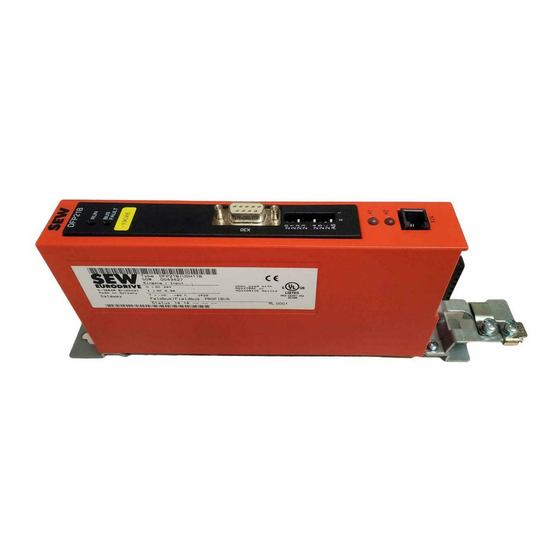
Fieldbus Interface DFP21B
PROFIBUS DP-V1
Edition 07/2006
M
anual
11479019 / EN
Related Manuals for SEW-Eurodrive DFP21B
Summary of Contents for SEW-Eurodrive DFP21B
-
Page 1
Gearmotors Industrial Gear Units Drive Electronics Drive Automation Services FA375100 Fieldbus Interface DFP21B PROFIBUS DP-V1 Edition 07/2006 anual 11479019 / EN… -
Page 2
SEW-EURODRIVE – Driving the world… -
Page 3
B ……..16 4.2.1 SBus connection …………….16 4.2.2 System bus connection…………..17 Assembling and installing the UOH11B gateway housing ……18 Connection and terminal description of the DFP21B option ……20 Pin assignment ……………….. 21 ® ® 4.5.1 MOVIDRIVE / MOVITRAC B / PROFIBUS connection …. -
Page 4
6.2.1 Control example for SIMATIC S7 with MOVITRAC B (gateway)..48 6.2.2 SBus timeout ………………48 6.2.3 Unit faults ………………. 48 6.2.4 Fieldbus timeout of the DFP21B in gateway operation…… 49 Parameter settings via PROFIBUS DP …………49 ® 6.3.1 Structure of the 8-byte MOVILINK parameter channel …. -
Page 5
List of errors ………………..98 10 Technical Data …………………. 99 ® 10.1 Option DFP21B for MOVIDRIVE MDX61B ……….99 ® 10.2 DFP21B option for MOVITRAC B and UOH11B gateway housing..100 11 Index ……………………101 Manual – Fieldbus Interface DFP21B PROFIBUS DP-V1… -
Page 6: Important Notes
Possible consequences: Damage to the unit and the environment Tips and useful information Part of the product The manual is a component of the DFP21B PROFIBUSDP-V1 fieldbus interface and contains important information for operation and service. Documentation reference • You must adhere to the information in the documentation to ensure: •…
-
Page 7: Liability For Defects
Incorrect handling or undertaking any action that is not specified in this manual could impair the properties of the product. If this is the case, you lose any right to claim against SEW-EURODRIVE GmbH & Co KG under limited warranty. Product names and trademarks The brands and product names named in these operating instructions are trademarks or registered trademarks of the titleholders.
-
Page 8: Safety Notes
Safety Notes Preliminary information Safety Notes • You are only allowed to perform installation and startup of the DFP21B field- bus interface when observing applicable accident prevention regulations and ® ® the MOVIDRIVE MDX60B/61B and MOVITRAC B operating instructions. Preliminary information…
-
Page 9: Installation / Assembly
Safety Notes Installation / assembly Installation / assembly Adhere to the instructions in section 4, «Assembly and Installation Notes». Startup / operation Adhere to the instructions in section 5, «Project Planning and Startup». Manual – DFP21B PROFIBUSDP-V1 Fieldbus Interface…
-
Page 10: Introduction
Features ® ® The MOVIDRIVE MDX61B drive inverter and MOVITRAC B frequency inverter allow you to use the DFP21B option to connect to higher-level automation systems via PROFI- BUS thanks to its powerful universal fieldbus interface. ® ® 3.3.1 MOVIDRIVE…
-
Page 11: Access To All Information
The PROFIBUS DP-V1 specification introduced new acyclical READ/WRITE services as part of the PROFIBUSDP expansions. These acyclical services are added to the cur- rent cyclical bus operation in special telegrams to ensure compatibility of PROFIBUS DP and PROFIBUS DP V1. Manual – DFP21B PROFIBUSDP-V1 Fieldbus Interface…
-
Page 12: Configuring The Profibus Option Card
(such as with a conveyor belt). As the control terminals also function in fieldbus opera- tion, you can still implement fieldbus-independent emergency stop concepts via the terminals of the drive inverter. Manual – DFP21B PROFIBUSDP-V1 Fieldbus Interface…
-
Page 13: Diagnostics
The fieldbus monitor function in conjunction with the ® MOVITOOLS MotionStudio PC software offers you an easy-to-use diagnostic tool for setting all drive parameters (including the fieldbus parameters) and for displaying the fieldbus and device status information in detail. Manual – DFP21B PROFIBUSDP-V1 Fieldbus Interface…
-
Page 14: Assembly And Installation Notes
Assembly and Installation Notes Installing the DFP21B option card in MOVIDRIVE® MDX61B Assembly and Installation Notes This section contains information about assembly and installation of the DFP21B option ® ® card in the MOVIDRIVE MDX61B, MOVITRAC B and UOH11B gateway housing.
-
Page 15: Installing And Removing An Option Card
Assembly and Installation Notes Installing the DFP21B option card in MOVIDRIVE® MDX61B 4.1.2 Installing and removing an option card 53001AXX ® Figure 2: Installing an option card in MOVIDRIVE MDX61B sizes 1 to 6 1. Remove the two retaining screws holding the card retaining bracket. Pull the card retaining bracket out evenly from the slot (do not twist!).
-
Page 16: Installing The Dfp21B Option Card In Movitrac ® B
Installing the DFP21B option card in MOVITRAC® B ® Installing the DFP21B option card in MOVITRAC ® • MOVITRAC B does not require special firmware status. • Only SEW-EURODRIVE engineers are allowed to install or remove option cards for ® MOVITRAC 4.2.1 SBus connection ® MOVITRAC DFP21B…
-
Page 17: System Bus Connection
Assembly and Installation Notes Installing the DFP21B option card in MOVITRAC® B To simplify cabling, the DFP21B can be supplied with DC 24V from X46.7 of the ® MOVITRAC to X26.7. ® MOVITRAC must be supplied with DC 24V at terminals X12.8 and X12.9 when supply- ®…
-
Page 18
Connect the system bus terminating resistor (S1 = ON) at the end of the system bus connection. Switch off the terminating resistor on the other units (S1 = OFF). The DFP21B gateway must always be connected either at the beginning or the end of the system bus connection and features a permanently installed terminating resistor. -
Page 19: Assembling And Installing The Uoh11B Gateway Housing
SC11 system bus +, CAN high X26:2 SC12 system bus, CAN low X26:3 GND, CAN GND X26:6 GND, CAN GND X26:7 DC 24 V The gateway housing has a power supply of DC 24V that is connected to X26. Manual – DFP21B PROFIBUSDP-V1 Fieldbus Interface…
-
Page 20: Connection And Terminal Description Of The Dfp21B Option
Connection and terminal description of the DFP21B option Connection and terminal description of the DFP21B option Part number PROFIBUS interface type DFP21B option: 824 240 2 The «PROFIBUS interface type DFP21B» option is only possible in conjunction with ® MOVIDRIVE MDX61B, not with MDX60B.
-
Page 21: Pin Assignment
(reference = pin 9) via pin 4 (CNTR-P). 4.5.2 Baud rates greater than 1.5 MBaud The DFP21B option with baud rates > 1.5 MBaud can only be operated with special 12- MBaud PROFIBUS connectors. Manual – DFP21B PROFIBUSDP-V1 Fieldbus Interface…
-
Page 22: Shielding And Routing Bus Cables
Use a plug with an integrated bus terminating resistor if the DFP21B option is at the beginning or end of a PROFIBUS segment and only one PROFIBUS cable is leading to the DFP21B.
-
Page 23: Setting The Station Address
→ Significance: 4 × 0 = 0 FAULT → Significance: 8 × 0 = 0 → Significance: 16 × 1 = 16 → Significance: 32 × 0 = 0 → Significance: 64 × 0 = 0 ADDRESS 59111AXX Manual – DFP21B PROFIBUSDP-V1 Fieldbus Interface…
-
Page 24: Operating Mode Displays: Option Dfp21B
Assembly and Installation Notes Operating mode displays: option DFP21B Operating mode displays: option DFP21B 4.9.1 PROFIBUS LEDs The PROFIBUS interface DFP21B option card has 2 LEDs that indicate the current status of the DFP21B option and the PROFIBUS system. DFP21B FAULT 58361AXX RUN LED (green) •…
-
Page 25
Gateway is configured correctly Flashing Bus scan Bus is being checked by the gateway LED H2 (green) is currently reserved. ® X-terminal X24 is the RS-485 interface for diagnostics via PC and MOVITOOLS MotionStudio. Manual – DFP21B PROFIBUSDP-V1 Fieldbus Interface… -
Page 26: Validity Of The Gsd Files For Dfp21B
This section provides you with information on project planning for the DP master and startup of the drive inverter for fieldbus operation. Current versions of the GSD files for the DFP21B option are available on the SEW homepage (http://www.sew-eurodrive.de) under the heading «Software». Both GSD files can be used at the same time in one STEP7 project.
-
Page 27: Dp Master Project Planning The With Movidrive ® Gsd File
PROFIBUS options, a connection is not established between the DP-V1 master and DFP21B. In this case, the BUS FAULT LED of DFP21B remains switched on after the DP-V1 master has started. The DP V1 master will indicate that the connection cannot be established.
-
Page 28: Project Planning Procedure
5. Enter the I/O or peripheral addresses for the configured data widths. After project planning, you can start PROFIBUS DP. The red BUS FAULT LED indicates the status of the project planning (OFF = project planning OK). Manual – DFP21B PROFIBUSDP-V1 Fieldbus Interface…
-
Page 29
(PD4-PD10 can only be used with IPOSplus ® Param + 10 PD MOVIDRIVE control via 10 process data words Parameter setting via 8 byte parameter channel ® (PD4-PD10 can only be used with IPOSplus Manual – DFP21B PROFIBUSDP-V1 Fieldbus Interface… -
Page 30
7 process data words 16 I/O bytes or 8 I/O words 8 process data words 18 I/O bytes or 9 I/O words 9 process data words 20 I/O bytes or 10 I/O words 10 process data words Manual – DFP21B PROFIBUSDP-V1 Fieldbus Interface… -
Page 31
This would lead to undefined values being transmitted to the drive inverter. For PROFIBUS DP, data communication between the programmable controller and drive engineering devices is usually carried out with the setting «Data integrity over entire length». Manual – DFP21B PROFIBUSDP-V1 Fieldbus Interface… -
Page 32
DFP21 generates a diagnostic alarm when a malfunction occurs. 01 hex DFP21 does not generate a diagnostic alarm when a malfunction occurs (factory setting). Values not listed here are not permitted as they can cause malfunctions in the DFP21B. Manual – DFP21B PROFIBUSDP-V1 Fieldbus Interface… -
Page 33
Diagnostic alarms are generated even in case of an error (enabled = on) 00, 00, 00, 06, 81, 00, 00, 01, 01 Diagnostic alarms are not generated if there is an error (disabled = off, factory setting) Manual – DFP21B PROFIBUSDP-V1 Fieldbus Interface… -
Page 34: Dp Master Project Planning With Movitrac ® Or Gateway Gsd File
11328AEN Use the GSD file SEW_6009.GSD from the «DPV1» directory if you want to use the DFP21B as a gateway from PROFIBUS DP-V1 on the SBus to control the drive inverter. This GSD file corresponds to GSD revision 5. Refer to the manuals of the appropriate project planning software for details on the procedure.
-
Page 35: Profibus Dp Master Startup
Project Planning and Startup DP master project planning with MOVITRAC® or gateway GSD file 5.3.2 PROFIBUSDP master startup Supporting files for DFP21B gateway are available in the Internet at http://www.sew- eurodrive.de. • Observe the notes in the README.TXT file on the GSD disk.
-
Page 36: Configuration Of The Profibusdp Interface
EURODRIVE EURODRIVE EURODRIVE EURODRIVE EURODRIVE EURODRIVE EURODRIVE EURODRIVE EURODRIVE EURODRIVE EURODRIVE EURODRIVE EURODRIVE EURODRIVE EURODRIVE EURODRIVE EURODRIVE EURODRIVE EURODRIVE EURODRIVE EURODRIVE 59093AXX Figure 6: Data exchange with parameter data (Param) and process data (PD) Manual – DFP21B PROFIBUSDP-V1 Fieldbus Interface…
-
Page 37
The parame- ter channel is used for setting the parameters of the DFP21B and is not passed on to the connected stations. The fieldbus interface accepts between 1 to 24 process data words with and without parameter channel. -
Page 38
AS 8 Drives Control via 00hex C0hex, C0hex, C0hex, C0hex, C0hex, C0hex, C0hex, C0hex, (8 x 3 PD) 8×3 PD C2hex, C2hex, C2hex, C2hex, C2hex, C2hex, C2hex, C2hex, C2hex C2hex C2hex C2hex C2hex C2hex C2hex C2hex Manual – DFP21B PROFIBUSDP-V1 Fieldbus Interface… -
Page 39
PROFIBUS DP. This ensures mixed mode is run for DP-V1 and DP- capable modules. Depending on the specification of the master functionality, a DP-V1- capable station, that was configured using the DP-V1 GSD file, can run in the «DP» operating mode. Manual – DFP21B PROFIBUSDP-V1 Fieldbus Interface… -
Page 40: Autosetup For Gateway Operation
DIP switch off and back on again. As a first step, the DFP21B searches for drive inverters on the SBus below its hierarchi- cal level. This process is indicated by the H1 LED (system fault) flashing briefly. Different SBus addresses must be set for the drive inverters (P813).
-
Page 41
Project Planning and Startup DP master project planning with MOVITRAC® or gateway GSD file 59442AXX Figure 7: Data exchange DP-V1 master DFP inverter Manual – DFP21B PROFIBUSDP-V1 Fieldbus Interface… -
Page 42: Setting The Movidrive ® Mdx61B Drive Inverter
PROFIBUS without any further settings once the PROFIBUS option card has been installed. For example, all parameters can be set by the master programmable controller after being switched on. Manual – DFP21B PROFIBUSDP-V1 Fieldbus Interface…
-
Page 43: Setting The Movitrac ® Frequency Inverter
TROLLER INHIBIT) input terminal to a +24-V signal and to program input terminals ® DIØ1 … DIØ3 to NO FUNCTION. The procedure for startup of the MOVIDRIVE drive inverter with a fieldbus connection is described on the next page. ® Setting the MOVITRAC frequency inverter 11329AEN Manual – DFP21B PROFIBUSDP-V1 Fieldbus Interface…
-
Page 44
Set the parameter P881 SBus address to values between 1 to 8 in ascending order. The SBus address 0 is used by DFP21B gateway and therefore must not be used. Set P883 SBus timeout to values between 50 to 200 ms. -
Page 45: Controlling The Movidrive ® Mdx61B Drive Inverter
README_GSDA6003.PDF file included in the GSD file. • For more information about controlling via the process data channel, in particular regarding the coding of the control and status word, refer to the Fieldbus Unit Profile manual. Manual – DFP21B PROFIBUSDP-V1 Fieldbus Interface…
-
Page 46
P831 is used to set the parameters for the fault response, which is triggered by the field- bus timeout monitoring. The setting made here must correspond to the setting in the master system (S7: response monitoring). Manual – DFP21B PROFIBUSDP-V1 Fieldbus Interface… -
Page 47: Control Of The Movitrac ® Inverter (Gateway)
Address range MOVITRAC B, device 1 PO = process output data / PI = process input data Additional information on programming and project planning can be found in the README_GSD6009.PDF file included in the GSD file. Manual – DFP21B PROFIBUSDP-V1 Fieldbus Interface…
-
Page 48: Sbus Timeout
F111 system fault to be displayed on the fieldbus process input data for status words 1 of all drive inverters. The H1 LED (system fault) at the DFP21B then flashes at regular intervals. The exact error code is displayed in the status ®…
-
Page 49: Fieldbus Timeout Of The Dfp21B In Gateway Operation
PROFIBUSDP Operating Characteristics Parameter settings via PROFIBUS DP 6.2.4 Fieldbus timeout of the DFP21B in gateway operation You can set how the gateway should respond in case of timeout using the P831 Fieldbus timeout response parameter. No response The drives on the subordinate SBus continue with the last setpoint value.
-
Page 50
The service was executed if the hand- shake bit received in the control is identical with the transmitted handshake bit. Status bit 7 indicates whether it was possible to execute the service properly or if errors occurred. Manual – DFP21B PROFIBUSDP-V1 Fieldbus Interface… -
Page 51
Byte 2 Byte 3 Byte 4 Byte 5 Byte 6 Byte 7 Manage- Subindex Index high Index low Error class Error code Add. code Add. code ment high: Status bit = 1: Incorrect service execution Manual – DFP21B PROFIBUSDP-V1 Fieldbus Interface… -
Page 52: Reading A Parameter With Profibus Dp (Read)
READ service. This service is now activated in the drive inverter when the handshake bit changes. For example, it would be possible to activate the READ service with the management byte coding 01hex or 41hex. Manual – DFP21B PROFIBUSDP-V1 Fieldbus Interface…
-
Page 53: Writing A Parameter Via Profibus Dp (Write)
11 = 4 bytes Handshake bit Must be changed on every new task in cyclical transmission. Status bit 0 = No error during service execution 1 = Error during service execution 1) Bit value is changed Manual – DFP21B PROFIBUSDP-V1 Fieldbus Interface…
-
Page 54: Parameter Setting Procedure With Profibus Dp
When parameters are set via the fieldbus interface, the same parameter coding is used as with the serial RS-485 interfaces or the system bus. The data formats and ranges of values for the individual parameters can be found in the ® publication «MOVIDRIVE Parameter List». Manual – DFP21B PROFIBUSDP-V1 Fieldbus Interface…
-
Page 55: Simatic Step7 Program Example
TITLE =Copy PO data from DB3, word 20/22/24 to inverter CALL SFC 15 (DPWR_DAT) //WRITE DP Slave Record LADDR := W#16#240 //Output address 576 = 240hex RECORD := P#DB3.DBX 20.0 BYTE 6 //Pointer to DB/DW RET_VAL:= MW 32 //Result in flag word 32 Manual – DFP21B PROFIBUSDP-V1 Fieldbus Interface…
-
Page 56: Return Codes For Parameter Setting
For Error class 8 = other error , only error code = 0 (other error code) is defined. In this case, detailed identification is made using the Additional code . Manual – DFP21B PROFIBUSDP-V1 Fieldbus Interface…
-
Page 57: Additional Code
The following is a list of errors that can occur depending on the fieldbus option card used: • Incorrect coding of a service via parameter channel • Incorrect length specification of a service via parameter channel • Internal communication error Manual – DFP21B PROFIBUSDP-V1 Fieldbus Interface…
-
Page 58: Special Cases
Troubleshooting Repeat the READ or WRITE service. If this error occurs again, disconnect the drive inverter from the supply system and then reconnect it. Contact SEW Service for advice if this error occurs continuously. Manual – DFP21B PROFIBUSDP-V1 Fieldbus Interface…
-
Page 59: Profibus Dp-V1 Functions
…SEWMOVITOOLSFieldbus. The main features of PROFIBUS DP-V1 are explained below. C1-Master C2-Master C2-Master Cyclic OUT Data Param PROFIBUS DP-V1 Param Cyclic IN Data Acyclic DP-V1 C2-Services Acyclic DP-V1 Acyclic DP-V1 C1-Services C2-Services Drive 58617AXX Manual – DFP21B PROFIBUSDP-V1 Fieldbus Interface…
-
Page 60: Class 1 Master (C1 Master)
DP-V1 parameter channel for drives as of V3.1 in the PROFIdrive profile drive engineering of the PROFIBUS user group. Different procedures for accessing parameter data in the drive inverter are provided via this parameter channel. Manual – DFP21B PROFIBUSDP-V1 Fieldbus Interface…
-
Page 61: Dp-V1 Services
DP-V1 operation using the «DDLM_SlaveDiag» DP-V0 service. DP-V1 alarm handling has not been defined for drive engineering as a drive inverter does not usually transfer its status information via cyclical process data communication. Manual – DFP21B PROFIBUSDP-V1 Fieldbus Interface…
-
Page 62: Features Of Sew Drive Inverters
PLC) can also use an 8-byte MOVILINK parameter channel during cyclical data exchange to perform the parameter services with DFP21B. The READ and WRITE services give the C1 master access to connected stations via the DP-V1 C1 channel. Two additional C2 channels can be connected in parallel to these parameter channels.
-
Page 63: Structure Of The Dp-V1 Parameter Channel
The following MOVILINK services are supported: ® • 8-byte MOVILINK parameter channel with all the services supported by the drive inverter such as – READ parameter – WRITE parameter – WRITE parameter volatile – Etc. Manual – DFP21B PROFIBUSDP-V1 Fieldbus Interface…
-
Page 64
No. of values Unsigned8 0x00 … 0xEA Quantity 0 … 234 Error value Unsigned16 0x0000 … 0x0064 PROFIdrive error codes ® 0x0080 + MOVILINK additional code low ® For SEW MOVILINK 16-bit error value Manual – DFP21B PROFIBUSDP-V1 Fieldbus Interface… -
Page 65: Parameter Setting Procedure Via Data Set 47
READ.req DS47 without data Parameter Processing READ.res(-) without data READ.req DS47 without data Parameter Parameter READ.res(+) Response Response with data (parameter response) 53126AXX Figure 12: Telegram sequence for parameter access via PROFIBUSDP-V1 Manual – DFP21B PROFIBUSDP-V1 Fieldbus Interface…
-
Page 66: Dp-V1 Master Processing Sequence
Check Write. Write.response response negative Write.response positive Send DS_Read.req with parameter data Read. response status conflict? Other error or timeout Parameter transfer ok, Parameter transfer data available cancelled with ERROR 53127AEN Manual – DFP21B PROFIBUSDP-V1 Fieldbus Interface…
-
Page 67: Addressing Connected Drive Inverters
The actual service is defined by the data set element Attribute on the MOVILINK parameter channel. The high nibble of this element corresponds to the service nibble in the management byte of the DP parameter channel. Manual – DFP21B PROFIBUSDP-V1 Fieldbus Interface…
-
Page 68
Table 5: DP-V1 header of the positive READ.response with parameter response Service: READ.request Description Slot_Number Random, (is not evaluated) Index Index of the data set; constant index 47 Length 10 byte user data in response buffer Manual – DFP21B PROFIBUSDP-V1 Fieldbus Interface… -
Page 69
Lower-order part of the parameter value After sending this WRITE.request, the WRITE.response is received. If there was no status conflict in processing of the parameter channel, a positive WRITE.response results. Otherwise, the status fault is located in Error_code_1. Manual – DFP21B PROFIBUSDP-V1 Fieldbus Interface… -
Page 70
1 error code ® 6, 7 Error value 0x0811 MOVILINK return code e.g. Error class 0x08, Add. code 0x11 ® (see section «MOVILINK return code of the parameter settings for DP-V1» on page page 71) Manual – DFP21B PROFIBUSDP-V1 Fieldbus Interface… -
Page 71
Parameter may only be changed Autosetup is deactivated 0x0505 Incorrect coding of management and reserved byte 0x0602 Communication error between inverter system and fieldbus option card 0x0502 Timeout of secondary connection (such as during reset or with Sys-Fault) Manual – DFP21B PROFIBUSDP-V1 Fieldbus Interface… -
Page 72: Profidrive Parameter Requests
Access to parameter value No. of elements 0x00 0 = access to direct value, no subelement ® 6, 7 Parameter number 0x206C MOVILINK index 8300 = «Firmware version» 8, 9 Subindex 0x0000 Subindex 0 Manual – DFP21B PROFIBUSDP-V1 Fieldbus Interface…
-
Page 73
1 value 6, 7 Value Hi 0x311C Higher-order part of the parameter 8, 9 Value Lo 0x7289 Lower-order part of the parameter Decoding: 0x 311C 7289 = 823947913 dec >> firmware version 823 947 9.13 Manual – DFP21B PROFIBUSDP-V1 Fieldbus Interface… -
Page 74
Table 20: READ.req for requesting the parameter response Field Value Description Function_Num READ.req Slot_Number Slot_Number not used Index Index of the data set Length Maximum length of response buffer in the DP-V1 master Manual – DFP21B PROFIBUSDP-V1 Fieldbus Interface… -
Page 75
Error No. of values 0x01 1 error code ® 6, 7 Error value 0x0811 MOVILINK return code e.g. Error class 0x08, Add. code 0x11 ® (see section «MOVILINK return codes for DP-V1» on page Manual – DFP21B PROFIBUSDP-V1 Fieldbus Interface… -
Page 76
0x19 Axis does not exist Access to an axis that does not exist up to 0x64 Reserved – 0x65..0xFF Depends on the manufac- – turer Manual – DFP21B PROFIBUSDP-V1 Fieldbus Interface… -
Page 77: Project Planning For A C1 Master
A special GSD file SEWA6003.GSD is required for the project planning of a DP-V1 C1 master. This file activates the DP-V1 functions of the DFP21B. Therefore, the functions of the GSD file and the DFP21B firmware must correspond with one another. When you implement the DP-V1 functions, SEW-EURODRIVE provides you with two GSD files (see section 5.2.1 on page 26, section 5.2.2 on page 27 and section 5.3.1 on page 34).
-
Page 78: Example Program For Simatic S7
ParameterNumber : WORD ; //REQ: Parameternumber Subindex : WORD ; //REQ: Subindex Format : BYTE := B#16#43; Values : BYTE := B#16#1; WRITEData : DWORD ; //REQ: WRITEData END_STRUCT ; TimeoutCounter : WORD ; //Timeout counter END_VAR Manual – DFP21B PROFIBUSDP-V1 Fieldbus Interface…
-
Page 79
#fStaticWRITEReq; //Indicates whether the request was a MVLK READ request for data evaluation LEN: #iStaticReqLength; #wParameterIndex; #MVLK_Req.ParameterNumber; #wSubIndex; #MVLK_Req.Subindex; #dwWRITEData; //Data is written to the structure, no matter whether write or read access #MVLK_Req.WRITEData; Manual – DFP21B PROFIBUSDP-V1 Fieldbus Interface… -
Page 80
; //An error has occurred. Set error bit and reset busy bits #fBusy; #fStaticBusy; #fDPV1WRITEDone; #fDone; 1; //Issue error code 1 (S7 error) #bError; #dwTempStatus; //Return the S7 error code #dwData; #TimeoutCounter; //Reset timeout counter Manual – DFP21B PROFIBUSDP-V1 Fieldbus Interface… -
Page 81
#TimeoutCounter; //Reset timeout counter WRR: // //WRITERequest was performed 0; //Output parameter is filled with ZEROS #dwData; 0; //No error #bError; ; //Clear error bits #fDone; #fActivate; #fBusy; #fStaticBusy; #fDPV1WRITEDone; #TimeoutCounter; //Reset timeout counter Manual – DFP21B PROFIBUSDP-V1 Fieldbus Interface… -
Page 82
:= M 100.0,//Activation bit: Triggering a parameter request fBusy := M 100.1,//The parameter request is being processed or a timeout has occurred fDone := M 100.2);//The parameter request is finished END_FUNCTION Manual – DFP21B PROFIBUSDP-V1 Fieldbus Interface… -
Page 83: Technical Data Dp-V1 For The Gateway Operation And Movitrac
Number of parallel C2 connections: Supported data set: Index 47 Supported slot number: Recommended: 0 Manufacturer code: 10A hex (SEW-EURODRIVE) Profile ID: C2 response timeout Max. length C1 channel: 240 bytes Max. length C2 channel: 240 bytes Manual – DFP21B PROFIBUSDP-V1 Fieldbus Interface…
-
Page 84: Error Codes Of The Dp-V1 Services
0xA to 0xF = user specific 0xC = resource 0x0 = read constraint conflict 0x1 = write constraint conflict 0x2 = resource busy 0x3 = resource unavailable 0x4..0x7 = reserved 0x8..0xF = user specific 0xD…0xF = user specific Manual – DFP21B PROFIBUSDP-V1 Fieldbus Interface…
-
Page 85: Operation Of Movitools ® Motionstudio Via Profibus
A PG/PC PROFIBUS connection is configured and transferred to the programmable controller in NetPro / SIMATIC STEP7. If STEP7 version 5.3 SP3 is installed on your PC, the Softnet driver need not be installed on the diagnostics PC. Manual – DFP21B PROFIBUSDP-V1 Fieldbus Interface…
-
Page 86: Required Hardware
® • MOVITOOLS MotionStudio, version 5.20 or higher Installation • Install the PROFIBUS master card into the diagnostics PC and install the driver according to the manufacturers specifications. ® • Install the MOVITOOLS MotionStudio. Manual – DFP21B PROFIBUSDP-V1 Fieldbus Interface…
-
Page 87: Configuring Simatic Net
If SIMATIC STEP7 is installed on the computer and is started there from the program «Set PG-PC interface», the field for the access path is deactivated. Start the program via the start menu as described above. Manual – DFP21B PROFIBUSDP-V1 Fieldbus Interface…
-
Page 88
– Assign the PC a free address that is not yet reserved by other masters or slaves. – The baud rate must match the baud rate if the class 1 master. • Select «DP» as the profile or set the bus timing parameters according to the existing PROFIBUS network. Manual – DFP21B PROFIBUSDP-V1 Fieldbus Interface… -
Page 89
Everything has been correctly configured up to now when the «OK» status is displayed after pressing the «Test» button and all devices on the PROFIBUS are displayed using ® the «Read» button. You can now operate MOVITOOLS MotionStudio via PROFIBUS- DP-V1. Manual – DFP21B PROFIBUSDP-V1 Fieldbus Interface… -
Page 90: Configuration Of Sew Communication Server
8.6.1 Establishing communication ® MOVITOOLS MotionStudio allows you to communicate with the electronics products from SEW-EURODRIVE GmbH&CoKG via several, different communication paths at the same time. ® When you start MOVITOOLS MotionStudio, you will also start the SEW communication server, and an additional icon will appear in the Windows status bar.
-
Page 91
3. Configure the requested interface using drag and drop. Use the mouse to drag the required connection from the [Available Plugs] field to one of the four communication channels and enter the information in the dialog windows. 58656AXX Manual – DFP21B PROFIBUSDP-V1 Fieldbus Interface… -
Page 92
MotionStudio by activating the following dialog: 11311AEN The following message appears when attempting to establish communication with PROFIBUS: 11312AXX After the PROFIBUS connection is successfully started, the PB server icon appears in the Windows task bar. 11310AXX Manual – DFP21B PROFIBUSDP-V1 Fieldbus Interface… -
Page 93: Automatic Search For Connected Units (Unit Scan)
Use the mouse to highlight the unit you want to operate. Switch MOVITOOLS MotionStudio to online mode by pressing the «Online mode» button. 11316ADE • Now highlight the unit you want to operate and activate the plug-in menu using the right mouse button. Manual – DFP21B PROFIBUSDP-V1 Fieldbus Interface…
-
Page 94: Known Problems When Operating Movitools ® Motionstudio
Is the bus address of the PC still available for use? Operation via SIMATIC NET: • Is the check box «PG/PC is the only master on the bus» enabled/disabled? • Is the baud rate set correctly? Manual – DFP21B PROFIBUSDP-V1 Fieldbus Interface…
-
Page 95: Error Diagnostics
For more information dealing specifically with the inverter parameter settings for various ® fieldbus applications, refer to the Fieldbus Unit Profile and MOVIDRIVE Parameter List manual. In addition, read the current information on the GSD disk. Manual – DFP21B PROFIBUSDP-V1 Fieldbus Interface…
-
Page 96
Bus communication is functioning properly (for problems with controlling or setpoint selection via PROFIBUSDP, continue with Diagnostic problem2). Inverter does not detect the baud rate (P092 Baud rate fieldbus). ↓ Check the bus cabling. Modify the bus addresses. Manual – DFP21B PROFIBUSDP-V1 Fieldbus Interface… -
Page 97
(for example, SIMATIC S7, SFC 14 / 15). Setpoints are not transferred. Check whether the drive inverter has been enabled at the terminals. Correct the settings. Manual – DFP21B PROFIBUSDP-V1 Fieldbus Interface… -
Page 98: List Of Errors
DFP itself is in an error state. In this the error is still present, query the case, error F111 was reported to the error via diagnostic interface and per- control only via fieldbus. form the action described in this table. Manual – DFP21B PROFIBUSDP-V1 Fieldbus Interface…
-
Page 99: Technical Data
F3hex, F9hex = parameter channel +10 process data words (14 I/O words) Diagnostics data • Max. 8 bytes • Standard diagnostics: 6 bytes ® Tools for startup • PC program MOVITOOLS MotionStudio • DBG11B keypad Manual – DFP21B PROFIBUSDP-V1 Fieldbus Interface…
-
Page 100: Dfp21B Option For Movitrac ® B And Uoh11B Gateway Housing
Technical Data DFP21B option for MOVITRAC® B and UOH11B gateway housing ® 10.2 DFP21B option for MOVITRAC B and UOH11B gateway housing 22.5 59796AXX Figure 17: Device dimensions of the UOH11B gateway housing ® DFP21B option (MOVITRAC B gateway) Part number…
-
Page 101: Index
Error codes of the DP-V1 services ……84 Parameter channel management ……. 50 Error Diagnostics ……….95 Parameter channel structure ……49 Explanation of symbols ………6 Parameter channel, management …… 50 Parameter data format ……..54 Parameter settings Manual – Fieldbus Interface DFP21B PROFIBUS DP-V1…
-
Page 102
Timeout …………48 Service coding …………58 Setting ® MOVIDRIVE MDX61B drive inverter ..42 ® MOVITRAC B frequency inverter ….43 SEW communication server ……..90 Shielding ………….22 SIMATIC NET Configuration ……….87 SIMATIC S7 …………46 Program example ………78 Manual – Fieldbus Interface DFP21B PROFIBUS DP-V1… -
Page 103
Address List Address List Germany Headquarters Bruchsal SEW-EURODRIVE GmbH & Co KG Tel. +49 7251 75-0 Production Ernst-Blickle-Straße 42 Fax +49 7251 75-1970 Sales D-76646 Bruchsal http://www.sew-eurodrive.de P.O. Box sew@sew-eurodrive.de Postfach 3023 • D-76642 Bruchsal Service Central SEW-EURODRIVE GmbH & Co KG Tel. -
Page 104
Electro-Services Tel. +237 4322-99 Rue Drouot Akwa Fax +237 4277-03 B.P. 2024 Douala Canada Assembly Toronto SEW-EURODRIVE CO. OF CANADA LTD. Tel. +1 905 791-1553 Sales 210 Walker Drive Fax +1 905 791-2999 Service Bramalea, Ontario L6T3W1 http://www.sew-eurodrive.ca l.reynolds@sew-eurodrive.ca Vancouver SEW-EURODRIVE CO. -
Page 105
Address List China Production Tianjin SEW-EURODRIVE (Tianjin) Co., Ltd. Tel. +86 22 25322612 Assembly No. 46, 7th Avenue, TEDA Fax +86 22 25322611 Sales Tianjin 300457 gm-tianjin@sew-eurodrive.cn Service http://www.sew-eurodrive.com.cn Assembly Suzhou SEW-EURODRIVE (Suzhou) Co., Ltd. Tel. +86 512 62581781 Sales… -
Page 106
Tel. +972 3 5599511 Ahofer Str 34B / 228 Fax +972 3 5599512 58858 Holon lirazhandasa@barak-online.net Italy Assembly Milano SEW-EURODRIVE di R. Blickle & Co.s.a.s. Tel. +39 02 96 9801 Sales Via Bernini,14 Fax +39 02 96 799781 Service I-20020 Solaro (Milano) http://www.sew-eurodrive.it sewit@sew-eurodrive.it… -
Page 107
No. 95, Jalan Seroja 39, Taman Johor Jaya Fax +60 7 3541404 Service 81000 Johor Bahru, Johor sales@sew-eurodrive.com.my West Malaysia Mexico Assembly Queretaro SEW-EURODRIVE MEXIKO SA DE CV Tel. +52 442 1030-300 Sales SEM-981118-M93 Fax +52 442 1030-301 Service Tequisquiapan No. 102 http://www.sew-eurodrive.com.mx Parque Industrail Queretaro scmexico@seweurodrive.com.mx… -
Page 108
Address List Poland Assembly Lodz SEW-EURODRIVE Polska Sp.z.o.o. Tel. +48 42 67710-90 Sales ul. Techniczna 5 Fax +48 42 67710-99 Service PL-92-518 Lodz http://www.sew-eurodrive.pl sew@sew-eurodrive.pl Portugal Assembly Coimbra SEW-EURODRIVE, LDA. Tel. +351 231 20 9670 Sales Apartado 15 Fax +351 231 20 3685… -
Page 109
Address List South Africa Capetown SEW-EURODRIVE (PROPRIETARY) LIMITED Tel. +27 21 552-9820 Rainbow Park Fax +27 21 552-9830 Cnr. Racecourse & Omuramba Road Telex 576 062 Montague Gardens dswanepoel@sew.co.za Cape Town P.O.Box 36556 Chempet 7442 Cape Town Durban SEW-EURODRIVE (PROPRIETARY) LIMITED Tel. -
Page 110
Dallas, Texas 75237 csdallas@seweurodrive.com Additional addresses for service in the USA provided on request! Venezuela Assembly Valencia SEW-EURODRIVE Venezuela S.A. Tel. +58 241 832-9804 Sales Av. Norte Sur No. 3, Galpon 84-319 Fax +58 241 838-6275 Service Zona Industrial Municipal Norte http://www.sew-eurodrive.com.ve… -
Page 113
SEW-EURODRIVE – Driving the world… -
Page 114
Internet, available Anywhere. today. around the clock. SEW-EURODRIVE GmbH & Co KG P.O. Box 3023 · D-76642 Bruchsal / Germany Phone +49 7251 75-0 · Fax +49 7251 75-1970 sew@sew-eurodrive.com www.sew-eurodrive.com…
-
Contents
-
Table of Contents
-
Bookmarks
Quick Links
Gearmotors Industrial Gear Units Drive Electronics Drive Automation Services
FA375100
Fieldbus Interface DFP21B
PROFIBUS DP-V1
Edition 07/2006
M
anual
11479019 / EN
Related Manuals for SEW-Eurodrive DFP21B
Summary of Contents for SEW-Eurodrive DFP21B
-
Page 1
Gearmotors Industrial Gear Units Drive Electronics Drive Automation Services FA375100 Fieldbus Interface DFP21B PROFIBUS DP-V1 Edition 07/2006 anual 11479019 / EN… -
Page 2
SEW-EURODRIVE – Driving the world… -
Page 3
B ……..16 4.2.1 SBus connection …………….16 4.2.2 System bus connection…………..17 Assembling and installing the UOH11B gateway housing ……18 Connection and terminal description of the DFP21B option ……20 Pin assignment ……………….. 21 ® ® 4.5.1 MOVIDRIVE / MOVITRAC B / PROFIBUS connection …. -
Page 4
6.2.1 Control example for SIMATIC S7 with MOVITRAC B (gateway)..48 6.2.2 SBus timeout ………………48 6.2.3 Unit faults ………………. 48 6.2.4 Fieldbus timeout of the DFP21B in gateway operation…… 49 Parameter settings via PROFIBUS DP …………49 ® 6.3.1 Structure of the 8-byte MOVILINK parameter channel …. -
Page 5
List of errors ………………..98 10 Technical Data …………………. 99 ® 10.1 Option DFP21B for MOVIDRIVE MDX61B ……….99 ® 10.2 DFP21B option for MOVITRAC B and UOH11B gateway housing..100 11 Index ……………………101 Manual – Fieldbus Interface DFP21B PROFIBUS DP-V1… -
Page 6: Important Notes
Possible consequences: Damage to the unit and the environment Tips and useful information Part of the product The manual is a component of the DFP21B PROFIBUSDP-V1 fieldbus interface and contains important information for operation and service. Documentation reference • You must adhere to the information in the documentation to ensure: •…
-
Page 7: Liability For Defects
Incorrect handling or undertaking any action that is not specified in this manual could impair the properties of the product. If this is the case, you lose any right to claim against SEW-EURODRIVE GmbH & Co KG under limited warranty. Product names and trademarks The brands and product names named in these operating instructions are trademarks or registered trademarks of the titleholders.
-
Page 8: Safety Notes
Safety Notes Preliminary information Safety Notes • You are only allowed to perform installation and startup of the DFP21B field- bus interface when observing applicable accident prevention regulations and ® ® the MOVIDRIVE MDX60B/61B and MOVITRAC B operating instructions. Preliminary information…
-
Page 9: Installation / Assembly
Safety Notes Installation / assembly Installation / assembly Adhere to the instructions in section 4, «Assembly and Installation Notes». Startup / operation Adhere to the instructions in section 5, «Project Planning and Startup». Manual – DFP21B PROFIBUSDP-V1 Fieldbus Interface…
-
Page 10: Introduction
Features ® ® The MOVIDRIVE MDX61B drive inverter and MOVITRAC B frequency inverter allow you to use the DFP21B option to connect to higher-level automation systems via PROFI- BUS thanks to its powerful universal fieldbus interface. ® ® 3.3.1 MOVIDRIVE…
-
Page 11: Access To All Information
The PROFIBUS DP-V1 specification introduced new acyclical READ/WRITE services as part of the PROFIBUSDP expansions. These acyclical services are added to the cur- rent cyclical bus operation in special telegrams to ensure compatibility of PROFIBUS DP and PROFIBUS DP V1. Manual – DFP21B PROFIBUSDP-V1 Fieldbus Interface…
-
Page 12: Configuring The Profibus Option Card
(such as with a conveyor belt). As the control terminals also function in fieldbus opera- tion, you can still implement fieldbus-independent emergency stop concepts via the terminals of the drive inverter. Manual – DFP21B PROFIBUSDP-V1 Fieldbus Interface…
-
Page 13: Diagnostics
The fieldbus monitor function in conjunction with the ® MOVITOOLS MotionStudio PC software offers you an easy-to-use diagnostic tool for setting all drive parameters (including the fieldbus parameters) and for displaying the fieldbus and device status information in detail. Manual – DFP21B PROFIBUSDP-V1 Fieldbus Interface…
-
Page 14: Assembly And Installation Notes
Assembly and Installation Notes Installing the DFP21B option card in MOVIDRIVE® MDX61B Assembly and Installation Notes This section contains information about assembly and installation of the DFP21B option ® ® card in the MOVIDRIVE MDX61B, MOVITRAC B and UOH11B gateway housing.
-
Page 15: Installing And Removing An Option Card
Assembly and Installation Notes Installing the DFP21B option card in MOVIDRIVE® MDX61B 4.1.2 Installing and removing an option card 53001AXX ® Figure 2: Installing an option card in MOVIDRIVE MDX61B sizes 1 to 6 1. Remove the two retaining screws holding the card retaining bracket. Pull the card retaining bracket out evenly from the slot (do not twist!).
-
Page 16: Installing The Dfp21B Option Card In Movitrac ® B
Installing the DFP21B option card in MOVITRAC® B ® Installing the DFP21B option card in MOVITRAC ® • MOVITRAC B does not require special firmware status. • Only SEW-EURODRIVE engineers are allowed to install or remove option cards for ® MOVITRAC 4.2.1 SBus connection ® MOVITRAC DFP21B…
-
Page 17: System Bus Connection
Assembly and Installation Notes Installing the DFP21B option card in MOVITRAC® B To simplify cabling, the DFP21B can be supplied with DC 24V from X46.7 of the ® MOVITRAC to X26.7. ® MOVITRAC must be supplied with DC 24V at terminals X12.8 and X12.9 when supply- ®…
-
Page 18
Connect the system bus terminating resistor (S1 = ON) at the end of the system bus connection. Switch off the terminating resistor on the other units (S1 = OFF). The DFP21B gateway must always be connected either at the beginning or the end of the system bus connection and features a permanently installed terminating resistor. -
Page 19: Assembling And Installing The Uoh11B Gateway Housing
SC11 system bus +, CAN high X26:2 SC12 system bus, CAN low X26:3 GND, CAN GND X26:6 GND, CAN GND X26:7 DC 24 V The gateway housing has a power supply of DC 24V that is connected to X26. Manual – DFP21B PROFIBUSDP-V1 Fieldbus Interface…
-
Page 20: Connection And Terminal Description Of The Dfp21B Option
Connection and terminal description of the DFP21B option Connection and terminal description of the DFP21B option Part number PROFIBUS interface type DFP21B option: 824 240 2 The «PROFIBUS interface type DFP21B» option is only possible in conjunction with ® MOVIDRIVE MDX61B, not with MDX60B.
-
Page 21: Pin Assignment
(reference = pin 9) via pin 4 (CNTR-P). 4.5.2 Baud rates greater than 1.5 MBaud The DFP21B option with baud rates > 1.5 MBaud can only be operated with special 12- MBaud PROFIBUS connectors. Manual – DFP21B PROFIBUSDP-V1 Fieldbus Interface…
-
Page 22: Shielding And Routing Bus Cables
Use a plug with an integrated bus terminating resistor if the DFP21B option is at the beginning or end of a PROFIBUS segment and only one PROFIBUS cable is leading to the DFP21B.
-
Page 23: Setting The Station Address
→ Significance: 4 × 0 = 0 FAULT → Significance: 8 × 0 = 0 → Significance: 16 × 1 = 16 → Significance: 32 × 0 = 0 → Significance: 64 × 0 = 0 ADDRESS 59111AXX Manual – DFP21B PROFIBUSDP-V1 Fieldbus Interface…
-
Page 24: Operating Mode Displays: Option Dfp21B
Assembly and Installation Notes Operating mode displays: option DFP21B Operating mode displays: option DFP21B 4.9.1 PROFIBUS LEDs The PROFIBUS interface DFP21B option card has 2 LEDs that indicate the current status of the DFP21B option and the PROFIBUS system. DFP21B FAULT 58361AXX RUN LED (green) •…
-
Page 25
Gateway is configured correctly Flashing Bus scan Bus is being checked by the gateway LED H2 (green) is currently reserved. ® X-terminal X24 is the RS-485 interface for diagnostics via PC and MOVITOOLS MotionStudio. Manual – DFP21B PROFIBUSDP-V1 Fieldbus Interface… -
Page 26: Validity Of The Gsd Files For Dfp21B
This section provides you with information on project planning for the DP master and startup of the drive inverter for fieldbus operation. Current versions of the GSD files for the DFP21B option are available on the SEW homepage (http://www.sew-eurodrive.de) under the heading «Software». Both GSD files can be used at the same time in one STEP7 project.
-
Page 27: Dp Master Project Planning The With Movidrive ® Gsd File
PROFIBUS options, a connection is not established between the DP-V1 master and DFP21B. In this case, the BUS FAULT LED of DFP21B remains switched on after the DP-V1 master has started. The DP V1 master will indicate that the connection cannot be established.
-
Page 28: Project Planning Procedure
5. Enter the I/O or peripheral addresses for the configured data widths. After project planning, you can start PROFIBUS DP. The red BUS FAULT LED indicates the status of the project planning (OFF = project planning OK). Manual – DFP21B PROFIBUSDP-V1 Fieldbus Interface…
-
Page 29
(PD4-PD10 can only be used with IPOSplus ® Param + 10 PD MOVIDRIVE control via 10 process data words Parameter setting via 8 byte parameter channel ® (PD4-PD10 can only be used with IPOSplus Manual – DFP21B PROFIBUSDP-V1 Fieldbus Interface… -
Page 30
7 process data words 16 I/O bytes or 8 I/O words 8 process data words 18 I/O bytes or 9 I/O words 9 process data words 20 I/O bytes or 10 I/O words 10 process data words Manual – DFP21B PROFIBUSDP-V1 Fieldbus Interface… -
Page 31
This would lead to undefined values being transmitted to the drive inverter. For PROFIBUS DP, data communication between the programmable controller and drive engineering devices is usually carried out with the setting «Data integrity over entire length». Manual – DFP21B PROFIBUSDP-V1 Fieldbus Interface… -
Page 32
DFP21 generates a diagnostic alarm when a malfunction occurs. 01 hex DFP21 does not generate a diagnostic alarm when a malfunction occurs (factory setting). Values not listed here are not permitted as they can cause malfunctions in the DFP21B. Manual – DFP21B PROFIBUSDP-V1 Fieldbus Interface… -
Page 33
Diagnostic alarms are generated even in case of an error (enabled = on) 00, 00, 00, 06, 81, 00, 00, 01, 01 Diagnostic alarms are not generated if there is an error (disabled = off, factory setting) Manual – DFP21B PROFIBUSDP-V1 Fieldbus Interface… -
Page 34: Dp Master Project Planning With Movitrac ® Or Gateway Gsd File
11328AEN Use the GSD file SEW_6009.GSD from the «DPV1» directory if you want to use the DFP21B as a gateway from PROFIBUS DP-V1 on the SBus to control the drive inverter. This GSD file corresponds to GSD revision 5. Refer to the manuals of the appropriate project planning software for details on the procedure.
-
Page 35: Profibus Dp Master Startup
Project Planning and Startup DP master project planning with MOVITRAC® or gateway GSD file 5.3.2 PROFIBUSDP master startup Supporting files for DFP21B gateway are available in the Internet at http://www.sew- eurodrive.de. • Observe the notes in the README.TXT file on the GSD disk.
-
Page 36: Configuration Of The Profibusdp Interface
EURODRIVE EURODRIVE EURODRIVE EURODRIVE EURODRIVE EURODRIVE EURODRIVE EURODRIVE EURODRIVE EURODRIVE EURODRIVE EURODRIVE EURODRIVE EURODRIVE EURODRIVE EURODRIVE EURODRIVE EURODRIVE EURODRIVE EURODRIVE EURODRIVE 59093AXX Figure 6: Data exchange with parameter data (Param) and process data (PD) Manual – DFP21B PROFIBUSDP-V1 Fieldbus Interface…
-
Page 37
The parame- ter channel is used for setting the parameters of the DFP21B and is not passed on to the connected stations. The fieldbus interface accepts between 1 to 24 process data words with and without parameter channel. -
Page 38
AS 8 Drives Control via 00hex C0hex, C0hex, C0hex, C0hex, C0hex, C0hex, C0hex, C0hex, (8 x 3 PD) 8×3 PD C2hex, C2hex, C2hex, C2hex, C2hex, C2hex, C2hex, C2hex, C2hex C2hex C2hex C2hex C2hex C2hex C2hex C2hex Manual – DFP21B PROFIBUSDP-V1 Fieldbus Interface… -
Page 39
PROFIBUS DP. This ensures mixed mode is run for DP-V1 and DP- capable modules. Depending on the specification of the master functionality, a DP-V1- capable station, that was configured using the DP-V1 GSD file, can run in the «DP» operating mode. Manual – DFP21B PROFIBUSDP-V1 Fieldbus Interface… -
Page 40: Autosetup For Gateway Operation
DIP switch off and back on again. As a first step, the DFP21B searches for drive inverters on the SBus below its hierarchi- cal level. This process is indicated by the H1 LED (system fault) flashing briefly. Different SBus addresses must be set for the drive inverters (P813).
-
Page 41
Project Planning and Startup DP master project planning with MOVITRAC® or gateway GSD file 59442AXX Figure 7: Data exchange DP-V1 master DFP inverter Manual – DFP21B PROFIBUSDP-V1 Fieldbus Interface… -
Page 42: Setting The Movidrive ® Mdx61B Drive Inverter
PROFIBUS without any further settings once the PROFIBUS option card has been installed. For example, all parameters can be set by the master programmable controller after being switched on. Manual – DFP21B PROFIBUSDP-V1 Fieldbus Interface…
-
Page 43: Setting The Movitrac ® Frequency Inverter
TROLLER INHIBIT) input terminal to a +24-V signal and to program input terminals ® DIØ1 … DIØ3 to NO FUNCTION. The procedure for startup of the MOVIDRIVE drive inverter with a fieldbus connection is described on the next page. ® Setting the MOVITRAC frequency inverter 11329AEN Manual – DFP21B PROFIBUSDP-V1 Fieldbus Interface…
-
Page 44
Set the parameter P881 SBus address to values between 1 to 8 in ascending order. The SBus address 0 is used by DFP21B gateway and therefore must not be used. Set P883 SBus timeout to values between 50 to 200 ms. -
Page 45: Controlling The Movidrive ® Mdx61B Drive Inverter
README_GSDA6003.PDF file included in the GSD file. • For more information about controlling via the process data channel, in particular regarding the coding of the control and status word, refer to the Fieldbus Unit Profile manual. Manual – DFP21B PROFIBUSDP-V1 Fieldbus Interface…
-
Page 46
P831 is used to set the parameters for the fault response, which is triggered by the field- bus timeout monitoring. The setting made here must correspond to the setting in the master system (S7: response monitoring). Manual – DFP21B PROFIBUSDP-V1 Fieldbus Interface… -
Page 47: Control Of The Movitrac ® Inverter (Gateway)
Address range MOVITRAC B, device 1 PO = process output data / PI = process input data Additional information on programming and project planning can be found in the README_GSD6009.PDF file included in the GSD file. Manual – DFP21B PROFIBUSDP-V1 Fieldbus Interface…
-
Page 48: Sbus Timeout
F111 system fault to be displayed on the fieldbus process input data for status words 1 of all drive inverters. The H1 LED (system fault) at the DFP21B then flashes at regular intervals. The exact error code is displayed in the status ®…
-
Page 49: Fieldbus Timeout Of The Dfp21B In Gateway Operation
PROFIBUSDP Operating Characteristics Parameter settings via PROFIBUS DP 6.2.4 Fieldbus timeout of the DFP21B in gateway operation You can set how the gateway should respond in case of timeout using the P831 Fieldbus timeout response parameter. No response The drives on the subordinate SBus continue with the last setpoint value.
-
Page 50
The service was executed if the hand- shake bit received in the control is identical with the transmitted handshake bit. Status bit 7 indicates whether it was possible to execute the service properly or if errors occurred. Manual – DFP21B PROFIBUSDP-V1 Fieldbus Interface… -
Page 51
Byte 2 Byte 3 Byte 4 Byte 5 Byte 6 Byte 7 Manage- Subindex Index high Index low Error class Error code Add. code Add. code ment high: Status bit = 1: Incorrect service execution Manual – DFP21B PROFIBUSDP-V1 Fieldbus Interface… -
Page 52: Reading A Parameter With Profibus Dp (Read)
READ service. This service is now activated in the drive inverter when the handshake bit changes. For example, it would be possible to activate the READ service with the management byte coding 01hex or 41hex. Manual – DFP21B PROFIBUSDP-V1 Fieldbus Interface…
-
Page 53: Writing A Parameter Via Profibus Dp (Write)
11 = 4 bytes Handshake bit Must be changed on every new task in cyclical transmission. Status bit 0 = No error during service execution 1 = Error during service execution 1) Bit value is changed Manual – DFP21B PROFIBUSDP-V1 Fieldbus Interface…
-
Page 54: Parameter Setting Procedure With Profibus Dp
When parameters are set via the fieldbus interface, the same parameter coding is used as with the serial RS-485 interfaces or the system bus. The data formats and ranges of values for the individual parameters can be found in the ® publication «MOVIDRIVE Parameter List». Manual – DFP21B PROFIBUSDP-V1 Fieldbus Interface…
-
Page 55: Simatic Step7 Program Example
TITLE =Copy PO data from DB3, word 20/22/24 to inverter CALL SFC 15 (DPWR_DAT) //WRITE DP Slave Record LADDR := W#16#240 //Output address 576 = 240hex RECORD := P#DB3.DBX 20.0 BYTE 6 //Pointer to DB/DW RET_VAL:= MW 32 //Result in flag word 32 Manual – DFP21B PROFIBUSDP-V1 Fieldbus Interface…
-
Page 56: Return Codes For Parameter Setting
For Error class 8 = other error , only error code = 0 (other error code) is defined. In this case, detailed identification is made using the Additional code . Manual – DFP21B PROFIBUSDP-V1 Fieldbus Interface…
-
Page 57: Additional Code
The following is a list of errors that can occur depending on the fieldbus option card used: • Incorrect coding of a service via parameter channel • Incorrect length specification of a service via parameter channel • Internal communication error Manual – DFP21B PROFIBUSDP-V1 Fieldbus Interface…
-
Page 58: Special Cases
Troubleshooting Repeat the READ or WRITE service. If this error occurs again, disconnect the drive inverter from the supply system and then reconnect it. Contact SEW Service for advice if this error occurs continuously. Manual – DFP21B PROFIBUSDP-V1 Fieldbus Interface…
-
Page 59: Profibus Dp-V1 Functions
…SEWMOVITOOLSFieldbus. The main features of PROFIBUS DP-V1 are explained below. C1-Master C2-Master C2-Master Cyclic OUT Data Param PROFIBUS DP-V1 Param Cyclic IN Data Acyclic DP-V1 C2-Services Acyclic DP-V1 Acyclic DP-V1 C1-Services C2-Services Drive 58617AXX Manual – DFP21B PROFIBUSDP-V1 Fieldbus Interface…
-
Page 60: Class 1 Master (C1 Master)
DP-V1 parameter channel for drives as of V3.1 in the PROFIdrive profile drive engineering of the PROFIBUS user group. Different procedures for accessing parameter data in the drive inverter are provided via this parameter channel. Manual – DFP21B PROFIBUSDP-V1 Fieldbus Interface…
-
Page 61: Dp-V1 Services
DP-V1 operation using the «DDLM_SlaveDiag» DP-V0 service. DP-V1 alarm handling has not been defined for drive engineering as a drive inverter does not usually transfer its status information via cyclical process data communication. Manual – DFP21B PROFIBUSDP-V1 Fieldbus Interface…
-
Page 62: Features Of Sew Drive Inverters
PLC) can also use an 8-byte MOVILINK parameter channel during cyclical data exchange to perform the parameter services with DFP21B. The READ and WRITE services give the C1 master access to connected stations via the DP-V1 C1 channel. Two additional C2 channels can be connected in parallel to these parameter channels.
-
Page 63: Structure Of The Dp-V1 Parameter Channel
The following MOVILINK services are supported: ® • 8-byte MOVILINK parameter channel with all the services supported by the drive inverter such as – READ parameter – WRITE parameter – WRITE parameter volatile – Etc. Manual – DFP21B PROFIBUSDP-V1 Fieldbus Interface…
-
Page 64
No. of values Unsigned8 0x00 … 0xEA Quantity 0 … 234 Error value Unsigned16 0x0000 … 0x0064 PROFIdrive error codes ® 0x0080 + MOVILINK additional code low ® For SEW MOVILINK 16-bit error value Manual – DFP21B PROFIBUSDP-V1 Fieldbus Interface… -
Page 65: Parameter Setting Procedure Via Data Set 47
READ.req DS47 without data Parameter Processing READ.res(-) without data READ.req DS47 without data Parameter Parameter READ.res(+) Response Response with data (parameter response) 53126AXX Figure 12: Telegram sequence for parameter access via PROFIBUSDP-V1 Manual – DFP21B PROFIBUSDP-V1 Fieldbus Interface…
-
Page 66: Dp-V1 Master Processing Sequence
Check Write. Write.response response negative Write.response positive Send DS_Read.req with parameter data Read. response status conflict? Other error or timeout Parameter transfer ok, Parameter transfer data available cancelled with ERROR 53127AEN Manual – DFP21B PROFIBUSDP-V1 Fieldbus Interface…
-
Page 67: Addressing Connected Drive Inverters
The actual service is defined by the data set element Attribute on the MOVILINK parameter channel. The high nibble of this element corresponds to the service nibble in the management byte of the DP parameter channel. Manual – DFP21B PROFIBUSDP-V1 Fieldbus Interface…
-
Page 68
Table 5: DP-V1 header of the positive READ.response with parameter response Service: READ.request Description Slot_Number Random, (is not evaluated) Index Index of the data set; constant index 47 Length 10 byte user data in response buffer Manual – DFP21B PROFIBUSDP-V1 Fieldbus Interface… -
Page 69
Lower-order part of the parameter value After sending this WRITE.request, the WRITE.response is received. If there was no status conflict in processing of the parameter channel, a positive WRITE.response results. Otherwise, the status fault is located in Error_code_1. Manual – DFP21B PROFIBUSDP-V1 Fieldbus Interface… -
Page 70
1 error code ® 6, 7 Error value 0x0811 MOVILINK return code e.g. Error class 0x08, Add. code 0x11 ® (see section «MOVILINK return code of the parameter settings for DP-V1» on page page 71) Manual – DFP21B PROFIBUSDP-V1 Fieldbus Interface… -
Page 71
Parameter may only be changed Autosetup is deactivated 0x0505 Incorrect coding of management and reserved byte 0x0602 Communication error between inverter system and fieldbus option card 0x0502 Timeout of secondary connection (such as during reset or with Sys-Fault) Manual – DFP21B PROFIBUSDP-V1 Fieldbus Interface… -
Page 72: Profidrive Parameter Requests
Access to parameter value No. of elements 0x00 0 = access to direct value, no subelement ® 6, 7 Parameter number 0x206C MOVILINK index 8300 = «Firmware version» 8, 9 Subindex 0x0000 Subindex 0 Manual – DFP21B PROFIBUSDP-V1 Fieldbus Interface…
-
Page 73
1 value 6, 7 Value Hi 0x311C Higher-order part of the parameter 8, 9 Value Lo 0x7289 Lower-order part of the parameter Decoding: 0x 311C 7289 = 823947913 dec >> firmware version 823 947 9.13 Manual – DFP21B PROFIBUSDP-V1 Fieldbus Interface… -
Page 74
Table 20: READ.req for requesting the parameter response Field Value Description Function_Num READ.req Slot_Number Slot_Number not used Index Index of the data set Length Maximum length of response buffer in the DP-V1 master Manual – DFP21B PROFIBUSDP-V1 Fieldbus Interface… -
Page 75
Error No. of values 0x01 1 error code ® 6, 7 Error value 0x0811 MOVILINK return code e.g. Error class 0x08, Add. code 0x11 ® (see section «MOVILINK return codes for DP-V1» on page Manual – DFP21B PROFIBUSDP-V1 Fieldbus Interface… -
Page 76
0x19 Axis does not exist Access to an axis that does not exist up to 0x64 Reserved – 0x65..0xFF Depends on the manufac- – turer Manual – DFP21B PROFIBUSDP-V1 Fieldbus Interface… -
Page 77: Project Planning For A C1 Master
A special GSD file SEWA6003.GSD is required for the project planning of a DP-V1 C1 master. This file activates the DP-V1 functions of the DFP21B. Therefore, the functions of the GSD file and the DFP21B firmware must correspond with one another. When you implement the DP-V1 functions, SEW-EURODRIVE provides you with two GSD files (see section 5.2.1 on page 26, section 5.2.2 on page 27 and section 5.3.1 on page 34).
-
Page 78: Example Program For Simatic S7
ParameterNumber : WORD ; //REQ: Parameternumber Subindex : WORD ; //REQ: Subindex Format : BYTE := B#16#43; Values : BYTE := B#16#1; WRITEData : DWORD ; //REQ: WRITEData END_STRUCT ; TimeoutCounter : WORD ; //Timeout counter END_VAR Manual – DFP21B PROFIBUSDP-V1 Fieldbus Interface…
-
Page 79
#fStaticWRITEReq; //Indicates whether the request was a MVLK READ request for data evaluation LEN: #iStaticReqLength; #wParameterIndex; #MVLK_Req.ParameterNumber; #wSubIndex; #MVLK_Req.Subindex; #dwWRITEData; //Data is written to the structure, no matter whether write or read access #MVLK_Req.WRITEData; Manual – DFP21B PROFIBUSDP-V1 Fieldbus Interface… -
Page 80
; //An error has occurred. Set error bit and reset busy bits #fBusy; #fStaticBusy; #fDPV1WRITEDone; #fDone; 1; //Issue error code 1 (S7 error) #bError; #dwTempStatus; //Return the S7 error code #dwData; #TimeoutCounter; //Reset timeout counter Manual – DFP21B PROFIBUSDP-V1 Fieldbus Interface… -
Page 81
#TimeoutCounter; //Reset timeout counter WRR: // //WRITERequest was performed 0; //Output parameter is filled with ZEROS #dwData; 0; //No error #bError; ; //Clear error bits #fDone; #fActivate; #fBusy; #fStaticBusy; #fDPV1WRITEDone; #TimeoutCounter; //Reset timeout counter Manual – DFP21B PROFIBUSDP-V1 Fieldbus Interface… -
Page 82
:= M 100.0,//Activation bit: Triggering a parameter request fBusy := M 100.1,//The parameter request is being processed or a timeout has occurred fDone := M 100.2);//The parameter request is finished END_FUNCTION Manual – DFP21B PROFIBUSDP-V1 Fieldbus Interface… -
Page 83: Technical Data Dp-V1 For The Gateway Operation And Movitrac
Number of parallel C2 connections: Supported data set: Index 47 Supported slot number: Recommended: 0 Manufacturer code: 10A hex (SEW-EURODRIVE) Profile ID: C2 response timeout Max. length C1 channel: 240 bytes Max. length C2 channel: 240 bytes Manual – DFP21B PROFIBUSDP-V1 Fieldbus Interface…
-
Page 84: Error Codes Of The Dp-V1 Services
0xA to 0xF = user specific 0xC = resource 0x0 = read constraint conflict 0x1 = write constraint conflict 0x2 = resource busy 0x3 = resource unavailable 0x4..0x7 = reserved 0x8..0xF = user specific 0xD…0xF = user specific Manual – DFP21B PROFIBUSDP-V1 Fieldbus Interface…
-
Page 85: Operation Of Movitools ® Motionstudio Via Profibus
A PG/PC PROFIBUS connection is configured and transferred to the programmable controller in NetPro / SIMATIC STEP7. If STEP7 version 5.3 SP3 is installed on your PC, the Softnet driver need not be installed on the diagnostics PC. Manual – DFP21B PROFIBUSDP-V1 Fieldbus Interface…
-
Page 86: Required Hardware
® • MOVITOOLS MotionStudio, version 5.20 or higher Installation • Install the PROFIBUS master card into the diagnostics PC and install the driver according to the manufacturers specifications. ® • Install the MOVITOOLS MotionStudio. Manual – DFP21B PROFIBUSDP-V1 Fieldbus Interface…
-
Page 87: Configuring Simatic Net
If SIMATIC STEP7 is installed on the computer and is started there from the program «Set PG-PC interface», the field for the access path is deactivated. Start the program via the start menu as described above. Manual – DFP21B PROFIBUSDP-V1 Fieldbus Interface…
-
Page 88
– Assign the PC a free address that is not yet reserved by other masters or slaves. – The baud rate must match the baud rate if the class 1 master. • Select «DP» as the profile or set the bus timing parameters according to the existing PROFIBUS network. Manual – DFP21B PROFIBUSDP-V1 Fieldbus Interface… -
Page 89
Everything has been correctly configured up to now when the «OK» status is displayed after pressing the «Test» button and all devices on the PROFIBUS are displayed using ® the «Read» button. You can now operate MOVITOOLS MotionStudio via PROFIBUS- DP-V1. Manual – DFP21B PROFIBUSDP-V1 Fieldbus Interface… -
Page 90: Configuration Of Sew Communication Server
8.6.1 Establishing communication ® MOVITOOLS MotionStudio allows you to communicate with the electronics products from SEW-EURODRIVE GmbH&CoKG via several, different communication paths at the same time. ® When you start MOVITOOLS MotionStudio, you will also start the SEW communication server, and an additional icon will appear in the Windows status bar.
-
Page 91
3. Configure the requested interface using drag and drop. Use the mouse to drag the required connection from the [Available Plugs] field to one of the four communication channels and enter the information in the dialog windows. 58656AXX Manual – DFP21B PROFIBUSDP-V1 Fieldbus Interface… -
Page 92
MotionStudio by activating the following dialog: 11311AEN The following message appears when attempting to establish communication with PROFIBUS: 11312AXX After the PROFIBUS connection is successfully started, the PB server icon appears in the Windows task bar. 11310AXX Manual – DFP21B PROFIBUSDP-V1 Fieldbus Interface… -
Page 93: Automatic Search For Connected Units (Unit Scan)
Use the mouse to highlight the unit you want to operate. Switch MOVITOOLS MotionStudio to online mode by pressing the «Online mode» button. 11316ADE • Now highlight the unit you want to operate and activate the plug-in menu using the right mouse button. Manual – DFP21B PROFIBUSDP-V1 Fieldbus Interface…
-
Page 94: Known Problems When Operating Movitools ® Motionstudio
Is the bus address of the PC still available for use? Operation via SIMATIC NET: • Is the check box «PG/PC is the only master on the bus» enabled/disabled? • Is the baud rate set correctly? Manual – DFP21B PROFIBUSDP-V1 Fieldbus Interface…
-
Page 95: Error Diagnostics
For more information dealing specifically with the inverter parameter settings for various ® fieldbus applications, refer to the Fieldbus Unit Profile and MOVIDRIVE Parameter List manual. In addition, read the current information on the GSD disk. Manual – DFP21B PROFIBUSDP-V1 Fieldbus Interface…
-
Page 96
Bus communication is functioning properly (for problems with controlling or setpoint selection via PROFIBUSDP, continue with Diagnostic problem2). Inverter does not detect the baud rate (P092 Baud rate fieldbus). ↓ Check the bus cabling. Modify the bus addresses. Manual – DFP21B PROFIBUSDP-V1 Fieldbus Interface… -
Page 97
(for example, SIMATIC S7, SFC 14 / 15). Setpoints are not transferred. Check whether the drive inverter has been enabled at the terminals. Correct the settings. Manual – DFP21B PROFIBUSDP-V1 Fieldbus Interface… -
Page 98: List Of Errors
DFP itself is in an error state. In this the error is still present, query the case, error F111 was reported to the error via diagnostic interface and per- control only via fieldbus. form the action described in this table. Manual – DFP21B PROFIBUSDP-V1 Fieldbus Interface…
-
Page 99: Technical Data
F3hex, F9hex = parameter channel +10 process data words (14 I/O words) Diagnostics data • Max. 8 bytes • Standard diagnostics: 6 bytes ® Tools for startup • PC program MOVITOOLS MotionStudio • DBG11B keypad Manual – DFP21B PROFIBUSDP-V1 Fieldbus Interface…
-
Page 100: Dfp21B Option For Movitrac ® B And Uoh11B Gateway Housing
Technical Data DFP21B option for MOVITRAC® B and UOH11B gateway housing ® 10.2 DFP21B option for MOVITRAC B and UOH11B gateway housing 22.5 59796AXX Figure 17: Device dimensions of the UOH11B gateway housing ® DFP21B option (MOVITRAC B gateway) Part number…
-
Page 101: Index
Error codes of the DP-V1 services ……84 Parameter channel management ……. 50 Error Diagnostics ……….95 Parameter channel structure ……49 Explanation of symbols ………6 Parameter channel, management …… 50 Parameter data format ……..54 Parameter settings Manual – Fieldbus Interface DFP21B PROFIBUS DP-V1…
-
Page 102
Timeout …………48 Service coding …………58 Setting ® MOVIDRIVE MDX61B drive inverter ..42 ® MOVITRAC B frequency inverter ….43 SEW communication server ……..90 Shielding ………….22 SIMATIC NET Configuration ……….87 SIMATIC S7 …………46 Program example ………78 Manual – Fieldbus Interface DFP21B PROFIBUS DP-V1… -
Page 103
Address List Address List Germany Headquarters Bruchsal SEW-EURODRIVE GmbH & Co KG Tel. +49 7251 75-0 Production Ernst-Blickle-Straße 42 Fax +49 7251 75-1970 Sales D-76646 Bruchsal http://www.sew-eurodrive.de P.O. Box sew@sew-eurodrive.de Postfach 3023 • D-76642 Bruchsal Service Central SEW-EURODRIVE GmbH & Co KG Tel. -
Page 104
Electro-Services Tel. +237 4322-99 Rue Drouot Akwa Fax +237 4277-03 B.P. 2024 Douala Canada Assembly Toronto SEW-EURODRIVE CO. OF CANADA LTD. Tel. +1 905 791-1553 Sales 210 Walker Drive Fax +1 905 791-2999 Service Bramalea, Ontario L6T3W1 http://www.sew-eurodrive.ca l.reynolds@sew-eurodrive.ca Vancouver SEW-EURODRIVE CO. -
Page 105
Address List China Production Tianjin SEW-EURODRIVE (Tianjin) Co., Ltd. Tel. +86 22 25322612 Assembly No. 46, 7th Avenue, TEDA Fax +86 22 25322611 Sales Tianjin 300457 gm-tianjin@sew-eurodrive.cn Service http://www.sew-eurodrive.com.cn Assembly Suzhou SEW-EURODRIVE (Suzhou) Co., Ltd. Tel. +86 512 62581781 Sales… -
Page 106
Tel. +972 3 5599511 Ahofer Str 34B / 228 Fax +972 3 5599512 58858 Holon lirazhandasa@barak-online.net Italy Assembly Milano SEW-EURODRIVE di R. Blickle & Co.s.a.s. Tel. +39 02 96 9801 Sales Via Bernini,14 Fax +39 02 96 799781 Service I-20020 Solaro (Milano) http://www.sew-eurodrive.it sewit@sew-eurodrive.it… -
Page 107
No. 95, Jalan Seroja 39, Taman Johor Jaya Fax +60 7 3541404 Service 81000 Johor Bahru, Johor sales@sew-eurodrive.com.my West Malaysia Mexico Assembly Queretaro SEW-EURODRIVE MEXIKO SA DE CV Tel. +52 442 1030-300 Sales SEM-981118-M93 Fax +52 442 1030-301 Service Tequisquiapan No. 102 http://www.sew-eurodrive.com.mx Parque Industrail Queretaro scmexico@seweurodrive.com.mx… -
Page 108
Address List Poland Assembly Lodz SEW-EURODRIVE Polska Sp.z.o.o. Tel. +48 42 67710-90 Sales ul. Techniczna 5 Fax +48 42 67710-99 Service PL-92-518 Lodz http://www.sew-eurodrive.pl sew@sew-eurodrive.pl Portugal Assembly Coimbra SEW-EURODRIVE, LDA. Tel. +351 231 20 9670 Sales Apartado 15 Fax +351 231 20 3685… -
Page 109
Address List South Africa Capetown SEW-EURODRIVE (PROPRIETARY) LIMITED Tel. +27 21 552-9820 Rainbow Park Fax +27 21 552-9830 Cnr. Racecourse & Omuramba Road Telex 576 062 Montague Gardens dswanepoel@sew.co.za Cape Town P.O.Box 36556 Chempet 7442 Cape Town Durban SEW-EURODRIVE (PROPRIETARY) LIMITED Tel. -
Page 110
Dallas, Texas 75237 csdallas@seweurodrive.com Additional addresses for service in the USA provided on request! Venezuela Assembly Valencia SEW-EURODRIVE Venezuela S.A. Tel. +58 241 832-9804 Sales Av. Norte Sur No. 3, Galpon 84-319 Fax +58 241 838-6275 Service Zona Industrial Municipal Norte http://www.sew-eurodrive.com.ve… -
Page 113
SEW-EURODRIVE – Driving the world… -
Page 114
Internet, available Anywhere. today. around the clock. SEW-EURODRIVE GmbH & Co KG P.O. Box 3023 · D-76642 Bruchsal / Germany Phone +49 7251 75-0 · Fax +49 7251 75-1970 sew@sew-eurodrive.com www.sew-eurodrive.com…
Ошибки частотных преобразователей: примеры и коды ошибок
Частотные преобразователи — это электронные или электротехнические устройства, предназначенные для изменения и регулировки частоты электрического напряжения. Сфера их использования очень широка: насосные станции, системы тепло- и водоснабжения, линии производства, конвейеры, лифты, центрифуги, мельницы, металлургические агрегаты, буровое оборудование и т. д.
Использование частотных преобразователей на промышленных объектах дает следующие преимущества:
- Возможность отказаться от регулирующего оборудования: дросселей, вариаторов, редукторов и др. Это существенно упрощает работу механической системы, снижает расходы на эксплуатацию и повышает ее надежность.
- Плавный разгон управляемого двигателя, защищающий его от механических ударов и пусковых токов, что продлевает срок его службы.
- Частотные преобразователи в паре с асинхронными двигателями можно использовать в качестве альтернативы для приводов постоянного тока.
- Максимально рациональное регулирование скорости контролируемых двигателей и связанных с этим технологических процедур.
- Экономия электроэнергии, благодаря устранению ее неоправданных трат.
Но, несмотря на свою надежность и эффективность, частотные преобразователи, как и любые электронные приборы, подвержены износу. Инженерная компания 555 специализируется на ремонте промышленной электроники, и в частности — на устранении ошибок частотных преобразователей. Наши специалисты готовы отремонтировать вышедшее из строя оборудование в кратчайшие сроки.
Основные виды и причины неисправностей
Опознать неисправности частотников позволяют коды ошибок, высвечивающиеся на мониторе устройства. Каждая такая комбинация символов указывает на совершенно конкретную проблему, и это помогает специалистам выработать правильную стратегию ремонта. Для начала рассмотрим типовые виды ошибок частотных преобразователей:
- Over Current или OC. Данный сигнал на мониторе устройства свидетельствует о его перегрузке. Если подобная проблема возникла при тестовом запуске, необходимо проверить соответствие токов регулятора и электрической машины, а также исправность электроцепей управляемого двигателя. Следует учесть, что некоторые модели частотников высвечивают ошибку Over Current при торможении, работе и запуске электродвигателя.
- Over Heat или ОН. Это сообщение указывает на превышение номинально допустимой температуры частотного преобразователя. Проще говоря — на его перегрев. Устранить проблему можно посредством чистки внутреннего вентилятора или установки дополнительной вентиляционной системы в бокс, где располагается преобразователь. В качестве профилактики следует размещать частотник в месте, гарантирующем эффективный отвод тепла.
- Over Load или OL. Такая ошибка преобразователя может быть вызвана двумя обстоятельствами: превышением на валу момента силы или перегревом управляемого двигателя. Чтобы устранить проблему, необходимо выполнить корректную настройку тепловой защиты. Для этого во время программирования устройства нужно задать требуемую величину тока и время срабатывания защитной функции.
- Low Voltage или LV. Ошибка высвечивается при снижении напряжения питания или обрыве фаз (одной или двух). Существует два варианта решения этой проблемы: «насильственная» остановка двигателя или настройка его работы в однофазном режиме.
- Over Voltage или OV. Такую надпись можно увидеть на мониторе при замедлении вращения двигателя. Для устранения неисправности необходимо воспользоваться одним из трех способов: переводом устройства в режим генератора, активацией тормозного резистора или перенастройкой системы защиты от повышенного напряжения.
Среди других типовых неисправностей преобразователя следует выделить вращение двигателя в неправильном направлении, невозможность его запуска, проблемы с торможением и разгоном и т. д. Каждое повреждение имеет под собой конкретные причины. Например, если двигатель разгоняется очень медленно, скорее всего, дело в срабатывании функции токоограничения в момент разгона.
В число наиболее распространенных причин неисправностей входят:
- Заводской брак. Как правило, фабричные дефекты дают о себе знать в течение гарантийного срока. Поэтому для их устранения следует обращаться к поставщику или в брендовый сервисный центр.
- Ошибки при монтаже. Чаще всего причиной неисправностей становится некорректная сборка схемы привода или установка частотника в неподходящем месте.
- Нарушение норм эксплуатации. Регламент технического обслуживания изложен в инструкции, прилагаемой к устройству. Игнорирование регламента может привести к выходу из строя полупроводниковых элементов, перегреванию частотного регулятора и другим неисправностям.
- Несоответствие частотного преобразователя условиям его эксплуатации. Основные критерии выбора частотника — электрические характеристики двигателя, исполнение, набор функций и т. д. Несоответствие параметров условиям его эксплуатации приводит к некорректной работе устройства, выходу из строя и многочисленным поломкам.
Теперь поговорим об ошибках преобразователя частоты более подробно и предметно. В качестве примера рассмотрим привод известного китайского бренда INVT ELECTRIC CO, серии GDXXX. Предлагаем вашему вниманию таблицу, в которой представлены коды ошибок устройства, их расшифровка, вероятные причины неисправностей, а также способы их устранения.
| Код ошибки | Расшифровка | Вероятные причины | Способы устранения |
| OUt1, 2, 3 | Ошибка фазы. | Отсутствие заземления или контакта при подсоединении кабеля; слишком маленькое время разгона. | Увеличение времени разгона; замена модуля IGBT; устранение неисправностей внешнего оборудования; переподключение кабеля. |
| OC1, 2, 3 | Токовая перегрузка при разгоне, торможении или постоянной скорости. | Чрезмерное время торможения или разгона; слишком высокое напряжение в сети; недостаточная мощность привода; потеря фазы или короткое замыкание «на землю»; воздействие внешнего фактора. |
Сокращение времени разгона; оптимизация питающего напряжения; приобретение привода с более высокой мощностью; проверка конфигурации выхода; устранение внешних помех. |
| OV1, 2, 3 | Сверхнапряжение при разгоне, торможении или постоянной скорости. | Напряжение на входе не соответствует параметрам привода; чрезмерная энергия торможения. |
Проверка входного напряжения; оптимизация времени торможения/разгона. |
| UV | Слишком низкое напряжение шины. | Пониженное напряжение питания. | Проверка и оптимизация входного напряжения. |
| OL1 | Перегрузка электродвигателя. | Слишком низкое питающее напряжение; неверно заданные параметры тока; чрезмерная нагрузка на электродвигатель. |
Проверка входного напряжения; настройка правильных параметров тока в двигателе; оптимизация нагрузки. |
| OL2 | Перегрузка преобразователя частоты. | Чрезмерно быстрый разгон; остановка двигателя; заниженное питающее напряжение; сверхнагрузка; длительная работа двигателя на низкой скорости. |
Увеличение времени разгона; снижение нагрузки на двигатель; проверка мощности двигателя и входного напряжения; приобретение привода с более высокой мощностью; замена двигателя. |
| OL3 | Перегрузка по электричеству. | Сигнализация перегрузки в соответствии с заданными параметрами. | Проверка нагрузки и точки перегрузки. |
| SPI | Потеря фаз входа. | Потеря колебания или фазы напряжения трех входных фаз. | Проверка и оптимизация входного напряжения и/или правильности монтажа. |
| SPO | Потеря фаз выхода. | Асимметричная нагрузка. | Проверка выхода, двигателя и кабеля. |
| OH1 | Перегревание выпрямителя. | Неисправность вентилятора или засорение вентиляционного канала; слишком высокая температура воздуха в помещении; чрезмерно затянутый запуск устройства. |
Замена вентилятора и проверка воздуховода; снижение температуры окружающей среды; проверка и восстановление воздухообмена; оптимизация мощности нагрузки; замена модуля IGBT; ремонт платы управления. |
| EF | Неисправность внешних элементов. | Повреждение клеммы SIn и/или других внешних клемм. | Замена пришедших в негодность клемм. |
| CE | Проблемы со связью. | Некорректная скорость в бодах; повреждение кабеля связи; неверно заданный адрес сообщения; серьезные помехи в кабеле. |
Оптимизация скорости в бодах; проверка кабеля связи; настройка правильного адреса сообщения; замена кабеля или оптимизация защиты от помех. |
| ItE | Проблемы с обнаружением тока. | Некорректное подключение платы управления; отсутствие вспомогательного напряжения; выход из строя индикаторов тока. |
Проверка разъема, датчиков и платы управления. |
| tE | Ошибка автоматической настройки. | Несоответствие мощностей двигателя и частотного преобразователя; неверно заданные параметры электродвигателя; серьезная разница между стандартными параметрами и параметрами автоматической настройки; выход времени на автонастройку. |
Установка параметров, указанных на шильдике двигателя; снижение нагрузки на двигатель; проверка параметров двигателя и его соединения; установка верхнего предела частоты на уровень «выше 2/3 номинальной частоты». |
| bCE | Неисправность тормозного модуля. | Разрыв тормозных коммуникаций или некорректная работа тормозной цепи; недостаток производительности внешнего тормозного резистора. |
Проверка тормозного модуля и замена тормозных кабелей; принудительное повышение мощности тормозного резистора. |
| ETH1, 2 | Короткое замыкание | Замыкание выхода преобразователя частоты «на землю»; неисправность в цепи определения тока. |
Проверка подключения двигателя и индикаторов тока; замена платы управления. |
| dEu | Отклонение скоростного режима. | Избыточная нагрузка. | Оптимизация нагрузки и увеличение времени обнаружения; проверка и при необходимости корректировка параметров управления. |
| STo | Несогласованность параметров. | Отсутствие параметров управления для синхронных электродвигателей; некорректно заданные параметры автоматической настройки; отсутствие подключения частотника к двигателю. |
Корректировка нагрузки на двигатель; установка корректных параметров управления; увеличение времени определения несогласованности. |
| PCE | Обрыв связи с блоком управления. | Повреждение проводов, обеспечивающих подключение к блоку управления; помехи в проводах, связанные с внешним фактором; некорректное функционирование цепи в основной плате и/или в клавиатуре. |
Замена проводов блока управления; проверка внешней среды и устранение источника помех; выполнение комплексного сервисного обслуживания устройства. |
| END | Сброс времени до заводских настроек. | Фактическое время функционирования преобразователя не соответствует внутреннему параметру продолжительности работы. | Корректировка настроек времени. |
| DNE | Проблема с загрузкой параметров. | Повреждение проводов, подключаемых к блоку управления; помехи в проводах; ошибка в базе данных панели управления. |
Замена проводов блока управления; сервисное обслуживание частотного преобразователя; повторная загрузка данных в панель управления. |
Преимущества ремонта в инженерной компании 555
- Огромный опыт в ремонте частотных преобразователей разных моделей и марок.
- Команда профессиональных специалистов.
- Экономия до 70 % средств по сравнению с приобретением нового оборудования.
- Оперативное выполнение работ (максимальный срок ремонта — 15 дней).
- Бесплатная консультация и предварительный осмотр для определения ремонтопригодности привода.
- Доступные цены и оплата только по результату работы.
- Гарантия на отремонтированное оборудование — 12 месяцев.
Обращайтесь к нам из любой точки России, через сайт или по телефону. Промышленная электроника — это очень сложное и специфичное оборудование, которое следует доверять только профессионалам.
Мы ремонтируем:
![]()

Компания ООО «Барс-Гидравлик Групп» на протяжении нескольких лет успешно сотрудничает с ООО «Инженерная компания 555» в вопросах ремонта сложного промышленного оборудования. За время работы наш партнер зарекомендовал себя с самой лучшей стороны. Заказы выполняются в кротчайшие сроки при соблюдении высокого качества работ. Организация приема и выдачи заказов четкая. Гарантийные обязательства выполняются в полном объеме.
Выражаем благодарность Вашим специалистам за профессионализм и оперативное решение поставленных задач.
Особенно хочется отметить высокую клиентоориентированность персонала Вашей компании, готовность помочь в самых сложных ситуациях.
Мы высоко ценим сложившиеся между нашими компаниями открытые и доверительные партнерские отношения и искренне желаем «Инженерной компании «555» долгих лет успеха и процветания.
Читать весь
отзыв

ООО «Инженерная компания «555» оказывала нашей компании услуги по ремонту электродвигателей и проявила пунктуальность, аккуратность и ответственность в работе.
Результат выполненных работ говорит о качественном оборудовании и высококвалифицированных кадрах.
Сотрудники компании готовы выполнить новые для себя виды работ и оказать консультационные услуги, что характеризует их как профессионалов своего дела.
Рекомендуем ООО «ИК «555» как ответственного и надежного поставщика услуг.
Читать весь
отзыв

Сообщаем, что наша организация сотрудничает с ООО «Инженерная компания «555» с мая 2016 года по настоящее время.
За этот период мы обращались к услугам компании более 10 раз.
Благодаря серьезному и квалифицированному подходу сотрудников ООО «Инженерная компания «555» ремонтные работы произведены качественно с учетом сроков, и обеспечены гарантийным сопровождением.
Планируем в дальнейшем работать с ООО «Инженерная компания «555»
Читать весь
отзыв

Уважаемый Дмитрий Васильевич!
ОАО «Октябрьский электровагоноремонтный завод» успешно работает с ООО «Инженерная компания «555» несколько лет, очень довольны данным сотрудничеством. В работе компании наибольшую ценность для нас представляет готовность работать на условиях, удобных Заказчику, качественный ремонт оборудования в заявленные сроки и самое главное, финансовая защищенность Заказчика. В инженерной компании работают внимательные, доброжелательные сотрудники, готовые в любой момент решить проблему Заказчика. Мы рады, что выбрали ООО «Инженерная компания «555» в качестве партнера. Гарантируем дальнейшее сотрудничество!
Читать весь
отзыв

ЗАО «Охтинское» выражает глубокую признательность и истинную благодарность ООО Инженерной компании «555» за качественную работу компании по ремонту сложного оборудования промышленной электроники, оперативность и технически грамотное отношение к работе в течении всего периода сотрудничества.
Мы надеемся на дальнейшее успешное развитие деловых отношений в сфере ремонта промышленной электроники.
Читать весь
отзыв
Преимущества сотрудничества с нами

Оплата только за результат — работающий блок

Гарантия на работоспособность блока целиком 12 месяцев

Срок ремонта от 5 до 15 дней

Бесплатный предварительный осмотр на предмет ремонтопригодности

Не вносим конструктивных изменений

Ремонт на компонентном уровне
Наша лаборатория расположена в Санкт-Петербурге, но обратиться за помощью вы можете из любой точки России.
Закажите обратный звонок или наберите в рабочее время многоканальный телефон
– +7 (800) 555-89-01 (звонок по России бесплатный).
Расскажите о своей проблеме и получите инструкцию к дальнейшим действиям.