SIRIUS
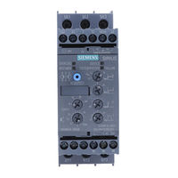
Sanftstarter 3RW40
Soft starter 3RW40
Démarreur progressif 3RW40
Arrancador suave 3RW40
Avviatore dolce 3RW40
Chave de partida suave 3RW40
Yumuşak yol verici 3RW40
Устройство плавного пуска 3RW40
软启动器 3RW40
Sanftstarter 3RW40
DE
Betriebsanleitung — Bestell-Nr.: 3ZX1012-0RW40-1AA1
Grafiken
Sicherheits- und Inbetriebnahmehinweise für explosionsgefährdete Bereiche — Bestell-Nr.: 3ZX1012-0RW40-1CA1
Soft starter 3RW40
EN
Operating Instructions — Order No.: 3ZX1012-0RW40-1AA1
Graphics
Safety and commissioning instructions for hazardous areas — Order No.: 3ZX1012-0RW40-1CA1
Démarreur progressif 3RW40
FR
Instructions de service — N° de référence : 3ZX1012-0RW40-1AA1
Graphiques
Consignes de sécurité et de mise en service pour les zones explosibles — N° de référence : 3ZX1012-0RW40-1CA1
Arrancador suave 3RW40
ES
Instructivo — Referencia: 3ZX1012-0RW40-1AA1
Gráficos
Instrucciones de seguridad y puesta en servicio en entornos con peligro de explosión — Referencia: 3ZX1012-0RW40-1CA1
Avviatore dolce 3RW40
IT
Istruzioni operative — N° di ordinaz.: 3ZX1012-0RW40-1AA1
Grafiche
Indicazioni di sicurezza e per la messa in servizio in aree con pericolo d’esplosione — N° di ordinaz.: 3ZX1012-0RW40-1CA1
Chave de partida suave 3RW40
PT
Instruções de Serviço — Nº de enc.: 3ZX1012-0RW40-1AA1
Gráficos
Indicações de segurança e de colocação em funcionamento para áreas apresentando risco de explosão —
Nº de enc.: 3ZX1012-0RW40-1CA1
Yumuşak yol verici 3RW40
TR
İşletme kılavuzu — Sipariş no.: 3ZX1012-0RW40-1AA1
Grafikler
Patlama tehlikesi altında bulunan bölgeler için emniyet ve hizmete alma bilgileri — Sipariş no.: 3ZX1012-0RW40-1CA1
Устройство плавного пуска 3RW40
PY
Инструкция по эксплуатации — № заказа: 3ZX1012-0RW40-1AA1
Графики
Указания по технике безопасности и вводу в эксплуатацию во взрывоопасных зонах — № заказа: 3ZX1012-0RW40-1CA1
软启动器 3RW40
操作规程 — 订货号:3ZX1012-0RW40-1AA1
中文
图表
用于受爆炸威胁区域的安全及首次启动运行说明 — 订购编号 : 3ZX1012-0RW40-1CA1
www.siemens.com/lowvoltage/manuals
SIRIUS-Systemhandbuch / SIRIUS system manual : http://www.siemens.de/sirius-systemhandbuch
Technical Assistance: Telephone: +49 (0) 911-895-5900 (8°° — 17°° CET)
E-mail:
Internet:
GWA 4NEB 535 2193-60 DS 01
technical-assistance@siemens.com
www.siemens.de/lowvoltage/technical-assistance
EN/IEC 60947-4-2
和 29 — 36 页
Fax: +49 (0) 911-895-5907
Last update: 08 October 2009
3RW40 5
3RW40 7
Seite
2 — 4
29 — 36
Page
5 — 7
29 — 36
Page
8 — 10
29 — 36
Página
11 — 13
29 — 36
Pagina
14 — 16
26 — 36
Página
17 — 19
29 — 36
Sayfa
20 — 22
29 — 36
Cтраница
23 — 25
29 — 36
第 26 — 28
SIRIUS
Sanftstarter
Soft starter
agodny rozruch
Arrancador suave
Avviatore dolce
Chave de partida suave
Betriebsanleitung
Operating Instructions
Instructivo
Istruzioni di servizio
Vor der Installation, dem Betrieb oder der Wartung des Geräts muss diese Anleitung gelesen und verstanden werden.
Read and understand these instructions before installing, operating, or maintaining the equipment.
Przeczytaj i zrozum poni sz instrukcj przed monta em, uruchomieniem i eksploatacj .
Leer y comprender este instructivo antes de la instalación, operación o mantenimiento del equipo.
Leggere con attenzione questi istruzioni prima di installare, utilizzare o eseguire manutenzione su questa apparecchiatura.
Ler e compreender estas instruções antes da instalação, operação ou manutenção do equipamento.
GEFAHR
!
Gefährliche Spannung. Lebensgefahr
oder Gefahr schwerer Verletzung.
Vor Beginn der Arbeiten Anlage und
Gerät spannungsfrei schalten.
!
PELIGRO
Tensión peligrosa.
Puede causar la muerte o lesiones
graves.
Desconectar la alimentación eléctrica
antes de trabajar en el equipo.
Eine sichere Gerätefunktion ist nur mit zertifizierten Komponenten gewährleistet.
Reliable functioning of the equipment is only ensured with certified components.
Niezawodne funkcjonowanie urz dzenia jest zapewnione tylko z autoryzowanymi komponentami.
El funcionamiento seguro del aparato sólo está garantizado con componentes certificados.
Il funzionamento sicuro dell’apparecchiatura viene garantito soltanto con componenti certificati.
O funcionamento seguro do aparelho apenas pode ser garantido se forem utilizados os componentes certificados.
Gefährliche Spannung.
Lebensgefahr oder schwere Verletzungsgefahr.
Um elektrischen Stro m sc hlagoder Verbrennungen zu
vermeiden, dürfen die Kl em m en des Motorsteuergeräts nicht
berührt werden, wenn das Gerät mit Spannung versorgt wird.
An den Ausgangskl em me n steht auch im AUS-Zu st and d es
Motorsteuergerä ts S pann ung an.
Niebezpieczne napi cie.
Mo e spowodowa mier lub powa ne obra enia.
Ab y unikn
dotyka zacisków aparatu, kiedy napi cie jest podane na
urz dzenia. Zaciski wyj cio we s pod napi cie m nawet, kiedy
urz dzenie jest wy czone.
Tensione pericolosa.
Può provocare morte o lesioni gravi.
Per evitare pericoli difolgorazione o di ustione, nontoccare i
morsetti dell’avviatore qua ndo l’apparecchiatura è sotto ten-
sione. I morsetti d’uscita sono sotto tensione anche quando
l’avviatore è disinserito.
GWA 4NEB 535 2193-10a
Instukcja obs ugi
Instruções de Serviço
DANGER
!
Hazardous voltage.
Will cause death or serious injury.
Disconnect power before working on
equipment.
!
PERICOLO
Tensione pericolosa.
Può provocare morte o lesioni gravi.
Scollegare l’alimentazione prima di
eseguire eventuali interventi
all’equipaggiamento.
GEFAHR
Niebezpiecze stwo
pora enia pr dem elektrycznym lu b poparzenia nie
PERICOLO
Bestell-Nr./Order No.: 3ZX1012-0RW40-1AA1
Niebezpiecze stwo
!
Niebezpieczne napi cie
Mo e spowodowa
obra enia.
Wy czy zasilanie przed prac przy
urz dzeniu.
!
PERIGO
Tensão perigosa.
Perigo de morte ou ferimentos graves.
Desligue a corrente antes de trabalhar
no equipamento.
DANGER
HAZARDOUS VOLTAGE.
Will cause death or serious injury.
To avoid electrical shock or burn, do not touch soft starter
terminals when voltage is applied t o the soft starter. Output
terminals will have voltage present evenw hen soft st arter is
O F F.
PELIGRO
Tensión peligrosa.
Puede causar la muerte o lesiones graves.
Para evitar todo riesgo de electrocución o de quema dura s,
no tocar los bornes del arrancador mientras estén bajo ten-
sión. Los bornes desalida están bajo tensión aunque el
arrancador esté desconectado (OF F).
PERIGO
Tensão perigosa.
Perigo de morte ou de ferimentos graves.
Para evitar qualqu e r risco de eletro cussão ou de queimadu-
ras, não toca r nos borne s do softstarter enqu anto este esti-
ver sob tensão. Os born e s de sa ída estão sob tensã o m esmo
quand o o softstarter está desligado (OFF).
Ostatnia zmiana: 24 Marzec 2005
3RW40
EN/IEC 60947-4-2
mier lub powa ne
- Manuals
- Brands
- Siemens Manuals
- Remote Starter
- SIRIUS 3RW40
Manuals and User Guides for Siemens SIRIUS 3RW40. We have 8 Siemens SIRIUS 3RW40 manuals available for free PDF download: Manual, Operating Instructions Manual

Siemens SIRIUS 3RW40 Manual (212 pages)
Soft starters
Brand: Siemens
|
Category: Controller
|
Size: 14.08 MB
Table of Contents
-
Table of Contents
5
-
1 Introduction
11
-
Important Notes
11
-
-
2 Safety Information
13
-
Before Commencing Work: Isolating the Equipment from the Supply System and Ensuring that It Cannot be Reconnected
13
-
Five Safety Rules for Work in or on Electrical Systems
13
-
-
3 Product Description
15
-
Fields of Application
15
-
Basic Physical Principles of a Three-Phase Induction Motor
15
-
Three-Phase Induction Motor
15
-
Operation
16
-
Functional Principle of the SIRIUS 3RW30 and 3RW40 Soft Starters
17
-
Method of Operation of a Two-Phase Controlled Soft Starter
20
-
Starting Current Asymmetry
21
-
Applications and Use
22
-
Commissioning
22
-
Comparison of Device Functions
24
-
-
4 Product Combinations
25
-
SIRIUS Modular System
25
-
Technical Data
25
-
-
5 Functions
27
-
Start Modes
27
-
Voltage Ramp
27
-
Current Limiting and Ramp-Up Detection (3RW40 Only)
29
-
Stop Modes
30
-
Stop Without Load (3RW30 and 3RW40)
31
-
Soft Stop (3RW40 Only)
31
-
Motor Protection / Intrinsic Device Protection (3RW40 Only)
32
-
Motor Protection Function
32
-
Intrinsic Device Protection (3RW40 Only)
35
-
Functions of the RESET Buttons
36
-
SIRIUS 3RW40 2, 3RW40 3, and 3RW40 4 Soft Starters
36
-
SIRIUS 3RW40 5 and 3RW40 7 Soft Starters
38
-
Other Functions of the RESET Button
39
-
Functions of the Inputs
40
-
Start Input (Terminal 1) on 3RW30 and 3RW40 2 to 3RW40 4
40
-
Start Input (Terminal 3) on 3RW40 5 and 3RW40 7
40
-
Thermistor Input / Connection on 3RW40 2 to 3RW40 4
41
-
Functions of the Outputs
41
-
3RW30: Output Terminal 13 / 14 on
41
-
3RW40: Output Terminals 13 / 14 on / RUN and 23 / 24 BYPASSED
42
-
3RW40: Group Fault Output at Terminal 95 / 96 / 98 OVERLOAD / FAILURE
43
-
Diagnostics and Fault Signals
44
-
3RW30: Leds and Troubleshooting
44
-
3RW40: Leds and Troubleshooting
46
-
-
6 Application Planning
51
-
Application Examples
51
-
Roller Conveyor Application
51
-
Hydraulic Pump Application
52
-
-
7 Installation
53
-
Installing the Soft Starter
53
-
Unpacking
53
-
Permissible Mounting Position
53
-
Mounting Dimensions, Clearances, and Assembly Type
54
-
Assembly Type: Standalone Assembly, Side-By-Side Assembly, Direct Mounting
55
-
Installation Requirements
56
-
-
8 Installation / Mounting
57
-
General Information
57
-
Five Safety Rules for Work in or on Electrical Systems
58
-
General Feeder Assembly (Type of Coordination 1)
59
-
Soft Starter with Line Contactor (Type of Coordination 1)
60
-
Soft Starter Assembly with Type of Coordination 2
61
-
Capacitors to Improve the Power Factor
62
-
Maximum Cable Length
63
-
-
9 Connecting
65
-
Electrical Connection
65
-
Control and Auxiliary Terminals
65
-
Main Circuit Connection
65
-
-
10 Operation
69
-
Operator Controls, Displays, and Connections on the 3RW30
69
-
Operator Controls, Displays, and Connections on the 3RW40
70
-
-
11 Configuration
73
-
Configuration in General
73
-
Configuration Procedure
73
-
Selecting the Optimum Soft Starter
74
-
Startup Class
76
-
Application Examples for Normal Starting (CLASS 10) with 3RW30 and 3RW40
77
-
Application Examples for Heavy-Duty Starting (CLASS 20): 3RW40 Only
78
-
ON Time and Switching Frequency
79
-
Reducing the Rated Data
80
-
Installation Altitude and Ambient Temperature
80
-
Calculating the Permissible Switching Frequency
81
-
Table of Permissible Assembly Combinations with Switching Frequency Factors
81
-
Calculating the Switching Frequency (Example)
84
-
Configuration Aids
86
-
Online Configurator
86
-
Win-Soft Starter Selection and Simulation Software
86
-
Technical Assistance
86
-
SIRIUS Soft Starter Training Course (SD-SIRIUSO)
87
-
Order Number System for the 3RW30
88
-
Order Number System for the 3RW40
89
-
-
12 Commissioning
91
-
Before Commencing Work: Isolating the Equipment from the Supply System and Ensuring that It Cannot be Reconnected
91
-
Commissioning the 3RW30
92
-
Commissioning Procedure
92
-
Quick Commissioning of the 3RW30 and Optimization of the Parameters
93
-
Setting the Soft Start Function
94
-
Setting the Starting Voltage
95
-
Setting the Ramp Time
95
-
ON Output
96
-
3RW30: Leds and Troubleshooting
97
-
Commissioning the 3RW40
98
-
Commissioning Procedure
99
-
Quick Commissioning of the 3RW40 and Optimization of the Parameters
100
-
Setting the Soft Start Function
101
-
Setting the Starting Voltage
102
-
Setting the Ramp Time
102
-
Current Limiting in Conjunction with a Starting Voltage Ramp and Ramp-Up Detection
103
-
Setting the Motor Current
103
-
Setting the Current Limiting Value
104
-
Ramp-Up Detection
104
-
Setting the Soft Stop Function
105
-
Setting the Ramp-Down Time
105
-
Setting the Motor Protection Function
105
-
Setting the Electronic Motor Overload Protection
106
-
Motor Current Settings
107
-
Motor Protection Acc. to ATEX
107
-
Thermistor Motor Protection
108
-
Motor Protection Trip Test
108
-
Functions of the Outputs
109
-
Functions of the BYPASSED and on / RUN Outputs
109
-
Parameterizing the 3RW40 Outputs
110
-
Function of the FAILURE / OVERLOAD Output
112
-
RESET MODE and Functions of the RESET / TEST Button
113
-
SIRIUS 3RW40 2. to 3RW40 4. Soft Starters
113
-
SIRIUS 3RW40 5. to 3RW40 7. Soft Starters
115
-
3RW40: Leds and Troubleshooting
117
-
-
13 Technical Data
121
-
Overview
121
-
Selection and Ordering Data for Standard Applications and Normal Starting
122
-
3Rw30
123
-
3Rw30
124
-
3Rw30 13, 14, 16, 17, 18-.Bb
124
-
3Rw30 26, 27, 28-.Bb
125
-
3Rw30 36, 37, 38, 46, 47-.Bb
125
-
3RW30 Main Conductor Cross-Sections
126
-
3RW30 Auxiliary Conductor Cross-Sections
127
-
Electromagnetic Compatibility According to en 60947-4-2
127
-
Recommended Filters
128
-
Types of Coordination
128
-
Fuseless Version
129
-
Fused Version (Line Protection Only)
130
-
Fused Version with SITOR 3NE1 Fuses
131
-
Fused Version with SITOR 3NE3/4/8 Fuses
132
-
Overview
134
-
Rw40
134
-
Selection and Ordering Data for Standard Applications and Normal Starting (CLASS 10)
135
-
Selection and Ordering Data for Standard Applications and Normal Starting (CLASS 10) (with Thermistor Motor Protection Evaluation)
137
-
Selection and Ordering Data for Standard Applications and Normal Starting (CLASS 10)
139
-
Selection and Ordering Data for Standard Applications and Heavy-Duty Starting (CLASS 20)
141
-
Selection and Ordering Data for Standard Applications and Heavy-Duty Starting (CLASS 20)
143
-
3RW40 2., 3., 4. Control Electronics
145
-
3RW40 5., 7. Control Electronics
145
-
3RW40 2., 3., 4. Control Electronics
146
-
3RW40 5., 7. Control Electronics
146
-
3RW40 Protection Functions
147
-
3RW40 Control Times and Parameters
147
-
3RW40 2. to 7. Power Electronics
148
-
3RW40 24, 26, 27, 28 Power Electronics
149
-
3RW40 36, 37, 38, 46, 47 Power Electronics
150
-
3RW40 55, 56, 73, 74, 75, 76 Power Electronics
151
-
3RW40 2., 3., 4. Main Conductor Cross-Sections
152
-
3RW40 5., 7. Main Conductor Cross-Sections
153
-
3Rw40
154
-
Electromagnetic Compatibility According to en 60947-4-2
154
-
Recommended Filters
155
-
Types of Coordination
155
-
Fuseless Version
156
-
Fused Version (Line Protection Only)
157
-
Fused Version with SITOR 3NE1 Fuses
158
-
Fused Version with SITOR 3NE3/4/8 Fuses
159
-
Motor Protection Tripping Characteristics for 3RW40 (with Symmetry)
161
-
Motor Protection Tripping Characteristics for 3RW40 (with Asymmetry)
161
-
Win-Soft Starter Selection and Simulation Software
162
-
-
14 Dimension Drawings
163
-
3RW30 for Standard Applications
163
-
3RW40 for Standard Applications
164
-
-
15 Typical Circuit Diagrams
167
-
Typical Circuit for the Optional Thermistor Motor Protection Evaluation
167
-
Control by Pushbutton
168
-
Control of the 3RW30 by Pushbutton
168
-
Control of the 3RW40 by Pushbutton
169
-
Control by Switch
170
-
Control of the 3RW30 by Switch
170
-
Control of the 3RW40 by Switch
171
-
Control in Automatic Mode
172
-
Control of the 3RW30 in Automatic Mode
172
-
Control of the 3RW40 in Automatic Mode
173
-
Control by PLC
175
-
Control of the 3RW30 with 24 V DC by PLC
175
-
Control of the 3RW40 by PLC
176
-
Control with an Optional Main / Line Contactor
177
-
Control of the 3RW30 with a Main Contactor
177
-
Control of the 3RW40 with a Main Contactor
178
-
Reversing Circuit
180
-
3RW30 Reversing Circuit
180
-
3RW40 Reversing Circuit
181
-
Control of a Magnetic Parking Brake
183
-
3RW30 Motor with Magnetic Parking Brake
183
-
3RW40 2 to 3RW40 4, Control of a Motor with a Magnetic Parking Brake
184
-
3RW40 5 to 3RW40 7, Control of a Motor with a Magnetic Parking Brake
185
-
Emergency Stop
186
-
3RW30 Emergency Stop and 3TK2823 Safety Relay
186
-
3RW40 2 to 3RW40 4 Emergency Stop and 3TK2823 Safety Relay
187
-
3RW40 5 to 3RW40 7 Emergency Stop and 3TK2823 Safety Relay
189
-
3RW and Contactor for Emergency Starting
191
-
3RW30 and Contactor for Emergency Starting
191
-
3RW40 and Contactor for Emergency Starting
192
-
Dahlander / Multispeed Motor
194
-
3RW30 and Dahlander Motor Starting
194
-
3RW40 2 to 3RW40 4 and Dahlander Motor Starting
195
-
3RW40 5 to 3RW40 7 and Dahlander Motor Starting
197
-
-
16 Accessories
199
-
Box Terminal Blocks for Soft Starters
199
-
Auxiliary Conductor Terminals
199
-
Covers for Soft Starters
199
-
Modules for RESET
200
-
Link Modules to 3RV10 Motor Starter Protectors
201
-
Link Modules to 3RV20 Motor Starter Protectors
201
-
Optional Fan to Increase the Switching Frequency (3RW40 2. to 3RW40 4.)
202
-
Spare Parts for Fans (3RW40 5., 3RW40 7.)
202
-
Operating Instructions
202
-
-
Appendix
203
-
Configuration Data
203
-
A.1 Configuration Data
203
-
Table of Parameters Used
205
-
Correction Sheet
206
-
A.3 Correction Sheet
206
-
Advertisement
Siemens SIRIUS 3RW40 Manual (204 pages)
Industrial Controls
Brand: Siemens
|
Category: Controller
|
Size: 24.82 MB
Table of Contents
-
Table of Contents
3
-
1 Introduction
9
-
Important Notes
9
-
Additional Documentation
11
-
Siemens Industry Online Support
13
-
Technical Assistance
15
-
Siemens Industry Online Support App
15
-
-
2 Safety Information
17
-
ESD Guidelines
17
-
Reactive Power Compensation
19
-
Electromagnetic Compatibility (EMC) According to IEC 60947-4-1
19
-
Security Information
20
-
Recycling and Disposal
21
-
Before Commencing Work: Isolating the Equipment from the Supply System and Ensuring that It Cannot be Reconnected
21
-
Five Safety Rules for Work in or on Electrical Systems
22
-
-
3 Product Description
23
-
Fields of Application
23
-
Functional Principle of the SIRIUS 3RW30 and 3RW40 Soft Starters
24
-
Method of Operation of a Two-Phase Controlled Soft Starter
26
-
Starting Current Asymmetry
28
-
Applications and Use
29
-
Comparison of Device Functions
30
-
Accessories
31
-
Accessories for 3RW30 Soft Starters
31
-
Accessories for 3RW40 Soft Starters
32
-
-
4 Product Combinations
33
-
SIRIUS Modular System
33
-
-
5 Functions
35
-
Start Modes
35
-
Voltage Ramp
35
-
Current Limiting and Ramp-Up Detection (3RW40 Only)
38
-
Stop Modes
40
-
Stop Without Load (3RW30 and 3RW40)
40
-
Soft Stop (3RW40 Only)
41
-
Motor Protection / Intrinsic Device Protection (3RW40 Only)
42
-
Motor Protection Function
42
-
Intrinsic Device Protection (3RW40 Only)
45
-
Functions of the RESET Buttons
47
-
SIRIUS 3RW402, 3RW403 and 3RW404 Soft Starters
47
-
Setting the RESET MODE
47
-
Manual RESET
48
-
Remote RESET
48
-
Auto RESET
48
-
Acknowledging Faults
49
-
SIRIUS 3RW405 and 3RW407 Soft Starters
49
-
Setting the RESET MODE
49
-
Manual RESET
49
-
Auto RESET
50
-
Acknowledging Faults
50
-
Other Functions of the RESET Button
50
-
Motor Protection Trip Test
50
-
Reparameterizing the on / RUN Output Contact
51
-
Reset Options for Fault Acknowledgement
51
-
Functions of the Inputs
52
-
Start Input (Terminal 1) on 3RW30 and 3RW402 to 3RW404
52
-
Start Input (Terminal 3) on 3RW405 and 3RW407
53
-
Thermistor Input / Connection on 3RW402 to 3RW404
53
-
Functions of the Outputs
54
-
3RW30: Output Terminal 13 / 14 on
54
-
3RW40: Output Terminals 13 / 14 on / RUN and 23 / 24 BYPASSED
54
-
3RW40: Group Fault Output at Terminal 95 / 96 / 98 OVERLOAD / FAILURE
56
-
-
6 Messages and Diagnosis
57
-
3RW30: Leds
57
-
3RW30: Troubleshooting
58
-
3RW402 / 3RW403 / 3RW404: Leds
59
-
3RW405 / 3RW407: Leds
61
-
3RW40: Troubleshooting
63
-
-
7 Application Planning
65
-
Application Examples
65
-
Roller Conveyor Application
65
-
Hydraulic Pump Application
66
-
-
8 Installation
67
-
Installing the Soft Starter
67
-
Unpacking
67
-
Permissible Mounting Position
67
-
Mounting Dimensions, Clearances, and Assembly Type
68
-
Assembly Type: Standalone Assembly, Side-By-Side Assembly, Direct Mounting
69
-
Installation Requirements
70
-
-
9 Installation / Mounting
71
-
General Information
71
-
General Feeder Assembly (Type of Coordination 1)
72
-
Soft Starter with Line Contactor (Type of Coordination 1)
73
-
Soft Starter Assembly with Type of Coordination 2
74
-
Capacitors to Improve the Power Factor
76
-
Maximum Cable Length
76
-
-
10 Connecting
77
-
Electrical Connection
77
-
Control and Auxiliary Terminals
77
-
Main Circuit Connection
77
-
-
11 Operation
81
-
Operator Controls, Displays, and Connections on the 3RW30
81
-
Operator Controls, Displays, and Connections on the 3RW40
82
-
Effects on Changing the Potentiometer Settings
84
-
-
12 Configuration
85
-
Configuration in General
85
-
Configuration Procedure
86
-
Selecting the Optimum Soft Starter
86
-
Startup Class
89
-
Application Examples for Normal Starting (CLASS 10) with 3RW30 and 3RW40
90
-
Application Examples for Heavy-Duty Starting (CLASS 20): 3RW40 Only
91
-
ON Time and Switching Frequency
92
-
Reducing the Rated Data
93
-
Dimensioning of Soft Starters for Motors with High Starting Current Conditions
93
-
Installation Altitude and Ambient Temperature
94
-
Calculating the Permissible Switching Frequency
95
-
Table of Permissible Assembly Combinations with Switching Frequency Factors
95
-
Calculating the Switching Frequency (Example)
98
-
Configuration Aids
100
-
Selection of the Soft Starter Using the Simulation Tool for Soft Starters
100
-
Article Number System for the 3RW30
101
-
Article Number System for the 3RW40
102
-
-
13 Commissioning
103
-
Commissioning the 3RW30
103
-
Commissioning Procedure
103
-
Quick Commissioning of the 3RW30 and Optimization of the Parameters
104
-
Setting the Soft Start Function
105
-
Setting the Starting Voltage
106
-
Setting the Ramp Time
106
-
ON Output
108
-
Commissioning the 3RW40
109
-
Commissioning Procedure
109
-
Quick Commissioning of the 3RW40 and Optimization of the Parameters
110
-
Setting the Soft Start Function
111
-
Setting the Starting Voltage
112
-
Setting the Ramp Time
112
-
Current Limiting in Conjunction with a Starting Voltage Ramp and Ramp-Up Detection
113
-
Setting the Motor Current
114
-
Setting the Current Limiting Value
114
-
Optimized Setting Ranges for Current Limiting
116
-
Ramp-Up Detection
117
-
Setting the Soft Stop Function
118
-
Setting the Ramp-Down Time
118
-
Setting the Motor Protection Function
119
-
Setting the Electronic Motor Overload Protection
119
-
Motor Current Settings
120
-
Motor Protection Acc. to ATEX
120
-
Thermistor Motor Protection
121
-
Motor Protection Trip Test
121
-
Functions of the Outputs
122
-
Functions of the BYPASSED and on / RUN Outputs
122
-
Parameterizing the 3RW40 Outputs
123
-
Function of the FAILURE / OVERLOAD Output
125
-
-
14 Technical Data
127
-
Technical Data in Siemens Industry Online Support
127
-
Overview
128
-
14.2 3Rw30
128
-
3Rw30
129
-
14.2 3Rw30
130
-
3Rw30 13, 14, 16, 17, 18-.Bb
130
-
3Rw30 26, 27, 28-.Bb
131
-
3Rw30 36, 37, 38, 46, 47-.Bb
131
-
3RW30 Main Conductor Cross-Sections
132
-
3RW30 Auxiliary Conductor Cross-Sections
133
-
Electromagnetic Compatibility According to en 60947-4-2
133
-
Recommended Filters
134
-
Types of Coordination
134
-
Fuseless Version
135
-
Fused Version (Line Protection Only)
136
-
Fused Version with SITOR 3NE1 Fuses
137
-
Fused Version with SITOR 3NE3/4/8 Fuses
138
-
Overview
140
-
Rw40
140
-
3RW40 2., 3., 4. Control Electronics
141
-
3RW40 5., 7. Control Electronics
142
-
3RW40 2., 3., 4. Control Electronics
142
-
3RW40 5., 7. Control Electronics
143
-
3RW40 Protection Functions
143
-
3RW40 Control Times and Parameters
144
-
3RW40 2. to 7. Power Electronics
145
-
3RW40 24, 26, 27, 28 Power Electronics
146
-
3RW40 36, 37, 38, 46, 47 Power Electronics
147
-
3RW40 55, 56, 73, 74, 75, 76 Power Electronics
148
-
3RW40 2., 3., 4. Main Conductor Cross-Sections
149
-
3RW40 5., 7. Main Conductor Cross-Sections
150
-
3Rw40
151
-
Electromagnetic Compatibility According to en 60947-4-2
151
-
Recommended Filters
152
-
Types of Coordination
152
-
Fuseless Version
153
-
Fused Version (Line Protection Only)
154
-
Fused Version with SITOR 3NE1 Fuses
155
-
Fused Version with SITOR 3NE3/4/8 Fuses
156
-
Motor Protection Tripping Characteristics for 3RW40 (with Symmetry)
157
-
Motor Protection Tripping Characteristics for 3RW40 (with Asymmetry)
158
-
-
15 Dimension Drawings
159
-
Cax Data
159
-
-
16 Typical Circuit Diagrams
161
-
Typical Circuit for the Optional Thermistor Motor Protection Evaluation
161
-
Control by Pushbutton
162
-
Control of the 3RW30 by Pushbutton
162
-
Control of the 3RW40 by Pushbutton
163
-
Control by Switch
165
-
Control of the 3RW30 by Switch
165
-
Control of the 3RW40 by Switch
166
-
Control in Automatic Mode
168
-
Control of the 3RW30 in Automatic Mode
168
-
Control of the 3RW40 in Automatic Mode
169
-
Control by PLC
171
-
Control of the 3RW30 with 24 V DC by PLC
171
-
Control of the 3RW40 by PLC
172
-
Control with an Optional Main / Line Contactor
174
-
Control of the 3RW30 with a Main Contactor
174
-
Control of the 3RW40 with a Main Contactor
175
-
Reversing Circuit
177
-
3RW30 Reversing Circuit
177
-
3RW40 Reversing Circuit
178
-
Control of a Magnetic Parking Brake
180
-
3RW30 Motor with Magnetic Parking Brake
180
-
3RW402 — 3RW404, Control of a Motor with a Magnetic Parking Brake
181
-
3RW405 — 3RW407, Control of a Motor with a Magnetic Parking Brake
182
-
Emergency Stop
183
-
3RW30 EMERGENCY STOP and 3TK2823 Safety Relay
183
-
3RW402 — 3RW404 EMERGENCY STOP and 3TK2823 Safety Relay
185
-
3RW405 — 3RW407 EMERGENCY STOP and 3TK2823 Safety Relay
187
-
3RW and Contactor for Emergency Starting
189
-
3RW30 and Contactor for Emergency Starting
189
-
3RW40 and Contactor for Emergency Starting
190
-
Dahlander / Multispeed Motor
192
-
3RW30 and Dahlander Motor Starting
192
-
3RW402 — 3RW404 and Dahlander Motor Starting
194
-
3RW405 — 3RW407 and Dahlander Motor Starting
195
-
-
Appendix
197
-
Configuration Data
197
-
A.1 Configuration Data
197
-
Table of Parameters Used
199
-
Index
201
-
Siemens SIRIUS 3RW40 Operating Instructions Manual (32 pages)
Brand: Siemens
|
Category: Controller
|
Size: 2.01 MB
Advertisement
Siemens SIRIUS 3RW40 Operating Instructions Manual (32 pages)
Brand: Siemens
|
Category: Controller
|
Size: 1.41 MB
Siemens SIRIUS 3RW40 Operating Instructions Manual (18 pages)
SIRIUS series
Brand: Siemens
|
Category: Controller
|
Size: 0.66 MB
Siemens SIRIUS 3RW40 Operating Instructions Manual (17 pages)
Brand: Siemens
|
Category: Controller
|
Size: 2.21 MB

Siemens SIRIUS 3RW40 Operating Instructions Manual (15 pages)
Brand: Siemens
|
Category: Controller
|
Size: 2.04 MB
Siemens SIRIUS 3RW40 Operating Instructions Manual (12 pages)
Soft starter
Brand: Siemens
|
Category: Remote Starter
|
Size: 1.59 MB
Advertisement
Related Products
-
Siemens SIRIUS 3RW40 2
-
Siemens SIRIUS 3RW40 3
-
Siemens SIRIUS 3RW40 4
-
Siemens SIRIUS 3RW40 7
-
Siemens SIRIUS 3RW40 5
-
Siemens SIRIUS 3RW40 24 Series
-
Siemens SIRIUS 3RW40 26 Series
-
Siemens SIRIUS 3RW40 27 Series
-
Siemens SIRIUS 3RW40 28 Series
-
Siemens SIRIUS 3RW40 36 Series
Siemens Categories
Controller
Control Unit
Industrial Equipment
![]()
Washer
![]()
Switch
More Siemens Manuals