- Manuals
- Brands
- Siemens Manuals
- Network Router
- SIMATIC ET 200SP
Manuals and User Guides for Siemens SIMATIC ET 200SP. We have 109 Siemens SIMATIC ET 200SP manuals available for free PDF download: Function Manual, System Manual, Manual, Operating Instructions Manual, User Manual, Equipment Manual, Product Information, Workshop Manual, Configuration Manual, Original Operating Instructions

Siemens SIMATIC ET 200SP Function Manual (362 pages)
Brand: Siemens
|
Category: Controller
|
Size: 10.73 MB
Table of Contents
-
Preface
4
-
Table of Contents
9
-
1 Function Manuals Documentation Guide
13
-
2 Product Overview
15
-
3 Communications Services
20
-
Overview of Communication Options
20
-
3.2 Communications Protocols and Port Numbers Used for Ethernet Communication
23
-
Overview of Connection Resources
28
-
Setting up a Connection
28
-
Data Consistency
32
-
Secure Communication
35
-
Basics of Secure Communication
35
-
Confidentiality through Encryption
37
-
Authenticity and Integrity through Signatures
40
-
Managing Certificates with STEP 7
44
-
Examples for the Management of Certificates
48
-
Example: HTTP over TLS
54
-
Snmp
58
-
Disabling SNMP
58
-
Example: Disabling SNMP for a CPU 1516-3 PN/DP
59
-
-
4 PG Communication
61
-
5 HMI Communication
64
-
6 Open User Communication
66
-
Overview of Open User Communication
66
-
Protocols for Open User Communication
67
-
Instructions for Open User Communication
69
-
Open User Communication with Addressing Via Domain Names
74
-
Setting up Open User Communication Via TCP, ISO-On-TCP, UDP and ISO
76
-
Setting up Communication over FDL
83
-
Setting up Communication with Modbus TCP
85
-
Setting up Communication Via E-Mail
88
-
Setting up Communication Via FTP
89
-
Establishment and Termination of Communications Relations
92
-
Secure Open User Communication
93
-
Secure OUC of an S7-1500 CPU as TLS Client to an External PLC (TLS Server)
93
-
Secure OUC of an S7-1500 CPU as TLS Server to an External PLC (TLS Client)
96
-
Secure OUC between Two S7-1500 Cpus
98
-
Secure OUC Via CP Interface
102
-
Secure OUC with Modbus TCP
107
-
Secure OUC Via E-Mail
108
-
-
7 S7 Communication
113
-
8 Point-To-Point Link
122
-
9 OPC UA Communication
127
-
What You Need to Know about OPC UA
127
-
OPC UA and Industrie 4.0
127
-
General Features of OPC UA
127
-
OPC UA for S7-1200/S7-1500 Cpus
131
-
Access to OPC UA Applications
132
-
Addressing Nodes
136
-
What You Need to Know about OPC UA Clients
140
-
Mapping of Data Types
143
-
Security at OPC UA
147
-
Security Settings
147
-
Certificates Pursuant to ITU X.509
148
-
Certificates with OPC UA
152
-
Creating Self-Signed Certificates
153
-
Generating PKI Key Pairs and Certificates Yourself
154
-
Secure Transfer of Messages
157
-
Using the S7-1500 as an OPC UA Server
160
-
Interesting Information about the OPC UA Server of the S7-1500 Cpus
160
-
The OPC UA Server of the S7-1500 Cpus
160
-
End Points of the OPC UA Server
162
-
Runtime Behavior of the OPC UA Server
164
-
Configuring Access to PLC Tags
166
-
Managing Write and Read Rights
166
-
Managing Write and Read Rights for a Complete DB
168
-
Coordinating Write and Read Rights for CPU Tags
170
-
Consistency of CPU Tags
172
-
Accessing OPC UA Server Data
174
-
Minimumsamplinginterval Attribute
175
-
Export OPC UA XML File
175
-
Configuring the OPC UA Server
176
-
Enabling the OPC UA Server
176
-
Access to the OPC UA Server
178
-
General Settings of the OPC UA Server
180
-
Settings of the Server for Subscriptions
182
-
Handling Client and Server Certificates
184
-
Generating Server Certificates with STEP 7
191
-
User Authentication
194
-
Users and Roles with OPC UA Function Rights
195
-
Diagnostic Settings of the Server
198
-
License for OPC UA
199
-
OPC UA Server Interface Configuration
200
-
What Is a Server Interface
200
-
Creating a User-Defined Server Interface
202
-
Using OPC UA Companion Specifications
207
-
Rules for OPC UA XML Files
214
-
Data Types for Companion Specifications
215
-
Creating a Server Interface for Companion Specification
219
-
Creating a Server Interface for Reference Namespace
224
-
Notes on Configuration Limits When Using Server Interfaces
227
-
Providing Methods on the OPC UA Server
228
-
Useful Information about Server Methods
228
-
Boundary Conditions for Using Server Methods
232
-
Using Diagnostics Options
234
-
Diagnostics of the OPC UA Server
234
-
Server State Transition Diagnostics
236
-
Session State Transition Diagnostics
237
-
Check for Security Events
238
-
Request of a Remote Client Failed
239
-
Subscription Diagnostics
241
-
Summarizing Diagnostics
244
-
Using the S7-1500 CPU as an OPC UA Client
246
-
Overview and Requirements
246
-
Useful Information about the Client Instructions
247
-
Number of Client Instructions that Can be Used Simultaneously
249
-
Example Configuration for OPC UA
250
-
Creating Client Interfaces
252
-
Determine Server Interface Online
261
-
Using Multilingual Texts
265
-
Rules for the Access to Structures
267
-
Using Connection Parameter Assignment
269
-
Creating and Configuring Connections
269
-
Handling of the Client Certificates of the S7-1500 CPU
273
-
User Authentication
276
-
Using a Configured Connection
277
-
Tips and Recommendations
285
-
Rules for Subscriptions
285
-
Rules for the User Program
286
-
Master Copies for OPC UA Communication
287
-
Advertisement
Siemens SIMATIC ET 200SP System Manual (320 pages)
Distributed I/O system
Brand: Siemens
|
Category: I/O Systems
|
Size: 10.02 MB
Table of Contents
-
Preface
4
-
Table of Contents
8
-
1 ET 200SP Documentation Guide
13
-
2 New Properties/Functions
15
-
3 System Overview
17
-
What Is the SIMATIC ET 200SP Distributed I/O System
17
-
What Are Fail-Safe Automation Systems and Fail-Safe Modules
20
-
How Are SIMATIC Safety F-Systems Structured with ET 200SP
21
-
Components
25
-
-
4 Application Planning
34
-
Selecting the Baseunit for I/O Modules
39
-
Digital, Fail-Safe, Communication, Technology or Analog Modules Without Temperature Measurement
39
-
Analog Modules with Temperature Measurement
40
-
Selecting Motor Starters with a Suitable Baseunit
41
-
Selecting a Baseunit for Motor Starters
41
-
Selecting the Motor Starter
43
-
Selecting Accessories for Motor Starters
44
-
Selecting Potential Distributor Modules
45
-
Selecting a Potdis-Baseunit
45
-
Selecting a Potdis-Terminalblock
47
-
Hardware Configuration
48
-
Forming Potential Groups
50
-
Basics
50
-
Forming Potential Groups with Baseunit Type B1
55
-
Forming Potential Groups with Fail-Safe Modules
56
-
Forming Potential Groups with Motor Starters
58
-
Configuration Examples for Potential Groups
60
-
Configuration Examples with Baseunits
60
-
Configuration Examples with Potential Distributor Modules
62
-
-
5 Installation
64
-
Basics
64
-
Installation Conditions for Motor Starters
68
-
Mounting the Cpu/Interface Module
70
-
Installing the CM DP Communication Module
72
-
Mounting Baseunits for I/O Modules
74
-
Mounting and Dismantling Baseunits for Motor Starters
77
-
Installing Potential Distributor Modules
79
-
Installing the Server Module
80
-
Mounting Further Accessories for Motor Starters
81
-
Mounting the Cover for the 500 V AC Infeed Bus
81
-
Mounting the Mechanical Bracket for the Baseunit
83
-
Mounting the BU Cover
86
-
-
6 Wiring
87
-
Rules and Regulations for Operation
87
-
Additional Rules and Regulations for the Operation of the ET 200SP with Fail-Safe Modules
89
-
Safety Extra-Low Voltage (SELV, PELV) for Failsafe Modules and Failsafe Motor Starters
89
-
Requirements for Sensors and Actuators for Fail-Safe Modules and Fail-Safe Motor Starters
90
-
Crosstalk of Digital Input/Output Signals
92
-
Additional Rules and Instructions for Operation with Motor Starters
93
-
Protection against Short Circuit
93
-
Operating the ET 200SP on Grounded Incoming Supply
93
-
Electrical Configuration of the ET 200SP
97
-
Wiring Rules
99
-
Wiring Baseunits for I/O Modules
102
-
Connecting Cable Shields for I/O Modules
104
-
Wiring Baseunits for Motor Starters
106
-
Connecting the 3DI/LC Module for the Motor Starter
110
-
Connecting the Supply Voltage to the Cpu/Interface Module
112
-
Connecting Interfaces for Communication
114
-
Connecting PROFINET IO (Port P3) to the CPU
114
-
Connecting the PROFIBUS DP Interface to the Interface Module/Communications Module CM DP
116
-
Inserting I/O Modules / Motor Starters and BU Covers
117
-
Mounting/Disassembly of Motor Starters
119
-
Mounting the Fan
119
-
Mounting/Disassembly of Motor Starters
120
-
3DI/LC Module
122
-
Labeling ET 200SP
125
-
Factory Markings
125
-
Optional Markings
127
-
Applying Color Identification Labels
128
-
Applying Labeling Strips
130
-
Applying Reference Identification Labels
131
-

Siemens SIMATIC ET 200SP Operating Instructions Manual (166 pages)
Technology module
Brand: Siemens
|
Category: Control Unit
|
Size: 4.7 MB
Table of Contents
-
Table of Contents
3
-
1 Introduction
11
-
Purpose of this Document
11
-
Use in Hazardous Area
11
-
Security Information
12
-
Open Source Software
13
-
-
2 Product Overview
15
-
View
15
-
Properties
16
-
Version Dependencies of the Functions
16
-
-
3 Installing
17
-
Basic Safety Notes
17
-
Atex/Iecx Special Conditions for Use
17
-
Mounting on the SIMATIC ET 200SP
18
-
EMC-Compliant Installation
19
-
Introduction
19
-
Possible Effects of Interference
19
-
Coupling Mechanisms
19
-
Five Basic Rules for Securing EMC
20
-
-
4 Connecting
23
-
Basic Safety Notes
23
-
Atex/Iecx Special Conditions for Use
23
-
Connection to Electronic Weighing System
24
-
Connection of Analog Load Cells
27
-
Connecting SIWAREX JB to the Electronic Weighing System and Load Cell
28
-
Wiring Diagrams
28
-
Load Cells with Four-Wire System
28
-
Load Cells with Six-Wire System
30
-
Connecting Cables to SIWAREX JB
31
-
-
5 Commissioning
33
-
Calibration with Calibration Weights
33
-
Automatic Calibration
35
-
-
6 Parameter Assignment/Addressing
37
-
Introduction
37
-
TIA Portal User Program
38
-
Commissioning the Electronic Weighing System with TIA Portal
38
-
Calling the Function Block (FB)
41
-
Executing Commands
44
-
Cyclic Data Exchange Via «Cycliciodata
46
-
Reading/Writing Data Records
48
-
Design of Hardware Configuration
49
-
Web Server
50
-
Calling the Web Server
50
-
Reading/Writing Data Records
51
-
Operating Modes
53
-
Weighing Steps
53
-
NAWI — Non Automatic Weighing Instrument
53
-
NAWI — Non-Automatic Weighing Instrument — Filling
53
-
NAWI — Non-Automatic Weighing Instrument — Emptying
54
-
GFI — Gravimetric Filling Instrument
55
-
CWI — Catchweighing Instrument / CW — Automatic Check Weigher
55
-
CWI — Catchweighing Instrument/ CW — Automatic Check Weigher — Filling
55
-
CWI — Catchweighing Instrument/ CW — Automatic Check Weigher — Emptying
56
-
DTI Discontinuous Totalizing Automatic Weighing Instrument
57
-
CW — Automatic Check Weigher
58
-
DR03 Calibration Parameters
58
-
Overview
58
-
Scale Name [Scalename]
59
-
Weight Unit [Weightunit]
59
-
Gross Indicator [Grossindicator]
59
-
Restriction Code [Restrictioncode]
60
-
Set Number of Weighing Ranges [Numberofweighingranges]
60
-
Multi Range / Multi Interval Scale [Multirangemultiintervalscale]
61
-
Calibration Weights 0, 1, 2, 3, 4 [Calibrationweight] and Calibration Digits [Calibrationdigit]
62
-
Scale Interval for Weighing Range 1, 2, 3 [Scaleintervalweighingrange]
63
-
Initial Zero-Setting [Initialzerosetting]
63
-
Initial Zero-Setting if Tared [Initialzerosettingiftared]
63
-
Automatic Zero Tracking Device [Automaticzerotracking]
63
-
Tare Device [Subtractiveadditivetare]
63
-
Enable Weight Simulation [Weightsimulationenabled]
64
-
Automatic Zero-Setting Device [Automaticzerosetting]
64
-
Weighing Range Data in Securedisplay [Weighingrangedatainsecuredisplay]
65
-
Automatic Zero Tracking in Dosing Cycle [Automaticzerotrackingincycle]
65
-
Maximum Tare Weight (% of Max.) [Maxtareweight]
65
-
Initial Zero-Setting Device Limit Negative (% of Max.) [Initialzerosettinglimitnegative]
65
-
Initial Zero-Setting Device Limit Positive (% of Max.) [Initialzerosettinglimitpositive]
65
-
Semi-Automatic Zero-Setting Device Limit Negative (% of Max.) [Semiautomaticzerosettinglimitnegative]
66
-
Semi-Automatic Zero-Setting Device Limit Positive (% of Max.) [Semiautomaticzerosettinglimitpositive]
66
-
Stability Monitoring
66
-
Digital Signal Filters
68
-
Operating Mode [Scaleoperatingmode]
69
-
Totalization Scale Interval Dt [Totalizationscaleintervaldt]
69
-
Minimum Totalized Load [Minimumtotalizedload]
69
-
Securedisplay Interface [Legaldisplayinterface]
69
-
Securedisplay Version [Securedisplayversion]
70
-
Smallest Zoom Factor of Securedisplay (%) [Smallestzoomfactorofsecuredisplay]
70
-
DR04 Calibration Curve Check
70
-
DR05 Tare and Zero Memory
70
-
DR06 Configuration of Limits
71
-
Reference (Limits 1 and 2) [Limitreference]
71
-
Limit 3 — Empty [Emptylimit]
71
-
Switch-On Delay Limit 3 (Empty) (S) [Delaytimeforemptylimit]
72
-
DR07 Interface Parameters
72
-
Assignment DI.0, DI.1, DI.2, CI [Functiondi0 to Functiondi2] [Functionci]
72
-
-
Filtering DI.0, DI.1, DI.2 and CI
73
-
Assignment DQ.0, DQ.1, DQ.2
73
-
Reaction to CPU Stop / Failure [Behaviouroncpustoporfailure]
73
-
Monitoring of Digital Outputs [Monitoringofdq]
74
-
Reaction of Digital Outputs to a CPU Stop / Failure [Behaviourofdqoncpustoporfailure]
74
-
Behavior of Digital Outputs on Error [Behaviourofdqonerror]
74
-
Substitute Value for DQ.0 to DQ.3 on Error
74
-
Trace Rate [Tracerate]
75
-
-
Subnet Mask, IP Address, Gateway, Device Name
75
-
Activate Modbus Communication [Activatemodbusconnection1] [Activatemodbusconnection2]
75
-
Modbus TCP Unit Identifier, Port, SWAP Options
76
-
Byte/Word Swap Options [Byteswap16Bit] [Byteswap32Bit] [Wordswap32Bit]
76
-
RS485 Protocol
76
-
I/O Process Values 1 to 4 [Ioprocessvalue1 to Ioprocessvalue4]
76
-
I/O Process Values 5 to 8 [Ioprocessvalue5 to Ioprocessvalue8]
77
-
Event Hardware Interrupts 4 to 8 [Hardwareinterrupt4 to Hardwareinterrupt8]
78
-
Source for Weight Simulation [Simulationsource]
78
-
DR09 Read out Module Information
78
-
DR10 Load Cell Parameters
78
-
Load Cell Type [Loadcelltype]
78
-
Connection Technology [Foursixwiresensor]
79
-
Load Cell Manufacturer [Loadcellmanufacturer] and Load Cell Order Number [Loadcellordernumber]
79
-
Of Mechanical Support Points [Numberofsupportpoints]
79
-
Averaged Load Cell Characteristic (MV/V) [Averagedcharacteristicvalue]
79
-
Nominal Load of One Single Load Cell [Nominalloadofsingleloadcell]
79
-
Power Line Frequency [Powerlinefrequency]
80
-
Using a Power Line Filter [Powerlinefilteractivated]
80
-
External / Internal Sensor Supply [Internalexternaladcsupply]
80
-
Impedance
80
-
DR15 Preset Tare
80
-
DR16 Configuration of Weight Simulation
81
-
Simulate Weight
81
-
Simulating Dosing
82
-
Material Flow, Delay Time and Opening/Closing Time
83
-
DR18 Digital Output and Transition Control
84
-
Controlling Digital Outputs
84
-
-
Enabling Transitions
85
-
DR20 Configuration of Set Point [Setpoint]
86
-
DR21 Configuration of Total Set Point [Totalsetpoint]
86
-
DR21 Configuration of Total Set Point in DTI
86
-
DR21 Configuration of Total Set Point GFI
87
-
DR22 Tolerance Parameters
88
-
Overview
88
-
Parameter Relation [Parameterrelation]
88
-
Tolerance Limit TH2 (Weight Unit) [Tolerancelimitth2]
88
-
Tolerance Limit TH1 (Weight Unit) [Tolerancelimitth1]
89
-
Tolerance Limit TL1 (Weight Unit) [Tolerancelimittl1]
89
-
Tolerance Limit TL2 (Weight Unit) [Tolerancelimittl2]
89
-
Behavior in Case of TH1 Error [Behaviorth1Violated]
89
-
Behavior in Case of TL1 Error [Behaviortl1Violated]
89
-
Pulse Duration for Pulse Post Dosing (S) [Pulseduration]
90
-
Number of Unchecked Weighing Cycles [Cycleswithoutcheck]
90
-
Capture of Weighings into Statistics [Statisticsdata]
91
-
DR23 Material Parameters
91
-
Parameter Relation [Parameterrelation]
91
-
Fine Weight [Fineweight]
91
-
Trailing Weight Fine [Trailingweightfine]
92
-
Coarse Weight [Coarseweight]
93
-
Trailing Weight Coarse [Trailingweightcoarse]
93
-
Trailing Weight Extra Coarse [Trailingweightxcoarse]
93
-
Blocking Time Extra Coarse (S) [Blockingtimexcoarse]
93
-
Blocking Time Coarse Signal (S) [Blockingtimecoarse]
94
-
Blocking Time Fine Signal (S) [Blockingtimefine]
94
-
Blocking Time Discharging (S) [Blockingtimedischarge]
94
-
External Triggered Blocking Time (S) [Externalblockingtime]
94
-
Shut-Off Correction Weight [Shutoffcorrectionweight]
94
-
Minimum Material Flow (Weight/S) [Minimummaterialflowrate]
95
-
DR24 Controller Parameters
95
-
Parameter Relation [Parameterrelation]
95
-
Type of Controller [Controllertype]
95
-
Control Factor of Proportional Controller (%) [Controlfactorpcontroller]
96
-
Control Factor of Fine Time Controller (%) [Controlfactortcontroller]
96
-
Max. Control Access of Proportional Controller [Maximumcontrollaccesspcontroller]
96
-
Proportional Controller Deadband — Upper Limit [Deadbandpcontrollerplus]
96
-
Proportional Controller Deadband — Lower Limit [Deadbandpcontrollerminus]
97
-
Controller Behavior in Case of Exceeding Max. Control Access [Controllererrorbehavior]
97
-
Intervention of Fine Time Controller [Interventiontcontroller]
97
-
Set Point Fine Time Controller (S) [Setpointtcontroller]
97
-
Adopt Corrected Fine-/Trailing Values to DR23 Automatically [Adoptcorrectedvalues]
98
-
Max. Control Access of Fine Time Controller [Maximumcontrollaccesstcontroller]
98
-
DR25 Dosing System Parameters
98
-
Maximum Single Set Point [Maximumsinglesetpoint]
98
-
Minimum Automatic Tare Weight (% of Max.) [Minimumautomatictareweight]
98
-
Maximum Automatic Tare Weight (% of Max.) [Maximumautomatictareweight]
98
-
Maximum Weighing Time (S) [Maximumdosingtime]
99
-
Weighing Start Options [Startoptions]
99
-
Cycle Time for Automatic Zero Setting (S) [Cycletimeautomaticzerosetting]
99
-
Number of Weighings Without Automatic Taring/Zero Setting [Numberofcycleswithoutzerosetting]
99
-
Check Stop [Checkstopafterstep0 to Checkstopafterstep7]
99
-
Automatic Discharging [Dischargemode]
100
-
Discharge Time (S) [Dischargetime]
101
-
Maximum Discharge Time (S) [Dischargemonitoringtime]
101
-
Discharge Overlapping Time [Dischargeoverlappingtime]
101
-
Of Optimized Loadings (OIML R-107) [Numberofoptimizedloadings]
101
-
Dosing Signals
102
-
Delete Tare in Weighing Step 0 [Deletetarestep0]
102
-
DR28 Configuration of Additional String for Protocols
102
-
Log with Additional String [Addadditionaltext]
102
-
Log Single Loadings (OIML R-107) [Logsingleloadings]
103
-
DR29 Configuration of Technology Messages
103
-
DR30 Read out Process State
103
-
Overview
103
-
Digits Unfiltered (Linearized) [Unfiltereddigitsnotlin]
104
-
Digits Filtered by F1 [Filtereddigits1]
104
-
Digits Filtered by F2 [Filtereddigits2]
104
-
Digits Filtered by F3 [Filtereddigits3]
104
-
Status DI.0, DI.1, DI.2 and CI.0 [Statusdi0] [Statusdi1] [Statusdi2] [Statusci0]
104
-
Status DQ.0, DQ.1 and DQ.2 [Statusdq0 to Statusdq2]
104
-
Refresh Counter [Refreshcounter]
105
-
Current Load Cell Signal Voltage (MV) [Loadcellsignalvoltage]
105
-
Load Cell Impedance (Ohm) [Loadcellimpedance]
105
-
Current Load Cell SEN Voltage (V) [Loadcellsensevoltage]
105
-
Current Fine Weight [Currentfineweight]
105
-
Current Trailing Weight [Currenttrailingweightfine]
105
-
Tolerance Limits (Weight Unit) [Tolerancelimitth2] [Tolerancelimitth1] [Tolerancelimittl1] [Tolerancelimittl2]
105
-
Gross Process Weight 1 [Grossprocessweight1], Net Process Weight 1
106
-
[Netprocessweight1], Tare Process Weight [Tareprocessweight]
106
-
-
Gross Weight [Grossweight], Net Weight [Netweight], Tare Weight [Tareweight]
106
-
Gross/Net Weight X10 [Netweightx10]
106
-
Gross Process Weight 2 [Grossprocessweight2], Net Process Weight 2
106
-
[Netprocessweight2]
106
-
-
Last Net Process Weight [Lastnetprocessweight], Last Net Weight [Lastnetweight]
106
-
Totalizer 1 [Totalizer1] and Totalizer 2 [Totalizer2]
106
-
Youngest Protocol ID [Youngestlogid]
106
-
Date & Time
107
-
Current Dosing Step [Subdosingstep]
107
-
Number of Dosings in Continuous Mode [Dosingsincontinuousmode]
107
-
Difference Set Point / Actual Value [Differencesetpointactualvalue]
107
-
DR32 Read out Error Messages
107
-
Overview
107
-
Operating Errors, Technology Messages, Data/Command Errors
107
-
DR34 Weight Indicator
108
-
DR38 Advanced Diagnostic Data
108
-
DR39 Statistical Data
108
-
DR45 Protocol Request
109
-
DR46 Read out Protocol Content
109
-
Overview
109
-
Oldest Protocol ID [Oldestlogid]
109
-
Youngest Protocol ID [Latestlogid]
109
-
Selected Protocol ID, Numerical [Selectedlogid]
109
-
Protocol String [Log]
110
-
Checksum, Date, Time
110
-
DR47 Read out Logbook Content
111
-
Commands
111
-
Overview
111
-
Commands
112
-
Command Groups of the Electronic Weighing System
118
-
Communication Via Modbus
118
-
Introduction
118
-
Principle of Data Transmission
119
-
Data Record Concept
119
-
Command Mailboxes
119
-
Reading Registers
120
-
Writing Registers
121
-
-
Advertisement
Siemens SIMATIC ET 200SP System Manual (271 pages)
Distributed I/O System
Brand: Siemens
|
Category: I/O Systems
|
Size: 9 MB
Table of Contents
-
Preface
4
-
Table of Contents
7
-
1 Guide to Documentation
11
-
2 System Overview
13
-
What Is the SIMATIC ET 200SP Distributed I/O System
13
-
What Are Fail-Safe Automation Systems and Fail-Safe Modules
16
-
How Are SIMATIC Safety F-Systems Structured with ET 200SP
17
-
Components
20
-
-
3 Application Planning
26
-
Selecting a Suitable Baseunit
26
-
Digital, Fail-Safe, Communication, Technology or Analog Modules Without Temperature Measurement
29
-
Analog Modules with Temperature Measurement
30
-
Hardware Configuration
31
-
Forming Potential Groups
32
-
Basics
32
-
Forming Potential Groups with AC I/O Modules
35
-
Forming Potential Groups with Fail-Safe Modules
36
-
Configuration Examples for Potential Groups
37
-
-
4 Installation
39
-
Basics
39
-
Mounting the Cpu/Interface Module
42
-
Installing the CM DP Communication Module
44
-
Installing Baseunits
45
-
Installing the Server Module
48
-
-
5 Wiring
49
-
Rules and Regulations for Operation
49
-
Additional Rules and Regulations for the Operation of the ET 200SP with Fail-Safe Modules
51
-
Safety Extra-Low Voltage (SELV) for Fail-Safe Modules
51
-
Requirements for Sensors and Actuators for Fail-Safe Modules
52
-
Crosstalk of Digital Input/Output Signals
55
-
Operating the ET 200SP on Grounded Incoming Supply
55
-
Electrical Configuration of the ET 200SP
58
-
Wiring Rules
60
-
Wiring Baseunits
62
-
Connecting Cable Shields
64
-
Connecting the Supply Voltage to the Cpu/Interface Module
66
-
Connecting Interfaces for Communication
68
-
Connecting PROFINET IO to the Cpu/Interface Module Via the Bus Adapter BA 2Xrj45
68
-
Connecting PROFINET IO to the Cpu/Interface Module Via the BA 2Xfc Busadapter
70
-
Connecting PROFINET IO to the Cpu/Interface Module Via BA 2Xscrj Busadapter
74
-
Connecting PROFINET IO to the Interface Module Via the BA SCRJ/RJ45 Busadapter
77
-
Connecting PROFINET IO to the Interface Module Via the BA SCRJ/FC Busadapter
79
-
Connecting PROFINET IO to the Interface Module Via the BA 2Xlc Busadapter
81
-
Connecting PROFINET IO to the Interface Module Via the BA LC/RJ45 Busadapter
84
-
Connecting PROFINET IO to Interface Module Via BA LC/FC Busadapter
86
-
Connecting PROFINET IO (Port P3) to the CPU
87
-
Connecting the PROFIBUS DP Interface to the Interface Module/Communications Module CM DP
89
-
Plugging in I/O Modules and BU Covers
90
-
Labeling ET 200SP
91
-
Factory Markings
91
-
Optional Markings
93
-
Applying Color Identification Labels
94
-
Applying Labeling Strips
96
-
Applying Reference Identification Labels
96
-

Siemens SIMATIC ET 200SP Manual (270 pages)
Analog input module AI Energy Meter 480VAC/CT HF
(6ES7134-6PA00-0CU0)
Brand: Siemens
|
Category: I/O Systems
|
Size: 8.25 MB
Table of Contents
-
Preface
4
-
Table of Contents
6
-
1 Documentation Guide
10
-
2 Product Overview
15
-
Properties of the AI Energy Meter HF
15
-
Area of Application
17
-
2.3 Special Considerations for Use on the PROFIBUS DP and PROFINET IO
19
-
-
3 Wiring
21
-
Terminal and Block Diagram
21
-
Connection Examples
24
-
Current Transformer Selection Data
28
-
-
4 Configuration / Address Space
32
-
Configuring
32
-
Selecting the Module Versions
33
-
Module Versions at Configuration with STEP 7
33
-
Module Versions at Configuration with GSD File
34
-
Changing over the User Data Variant During Operation
35
-
Recommendations for Selecting the Module Version
37
-
Applicable Modules
38
-
-
5 Quick Start
40
-
6 Reading and Processing Measured Values
42
-
Basics for Reading Measured Values
42
-
Quality Information
45
-
Quality Information in Byte 1 of the User Data
45
-
Quality Information with Measured Value Ids
47
-
Operating Quadrant
50
-
Reading Measured Values from User Data Cyclically
51
-
Read out Measured Values Acyclically Using Data Records
53
-
Time-Of-Day Synchronization and Time Stamp
54
-
-
7 Energy Counters
55
-
Evaluate Measured Values for Energy
56
-
Preset and Apply Start Values for Energy and Overflow Counters
57
-
Preset Start Values for the Energy Meters
58
-
Apply Start Values from Data Record DS 143 Immediately
59
-
Apply Start Values from Data Record DS 143 with DQ Bit
61
-
Starting and and Stopping Energy Meters
64
-
Example of Measuring and Resetting an Energy Meter
67
-
What Is the Structure of the Control and Feedback Interface for DS 143
68
-
-
8 Operating Hours Counter
70
-
Evaluating Operating Hours Counters
71
-
Preset and Apply Start Values for Operating Hours Counters
72
-
Preset Start Values for Operating Hours Counters
72
-
Apply Start Values from Data Record DS 143 Immediately
74
-
Apply Start Values from Data Record DS 143 with DQ Bit
74
-
Starting and Stopping Operating Hours Counters
76
-
-
9 Limit Monitoring
78
-
How Limit Monitoring Works
78
-
Influence of Hysteresis and Delay Time on Limit Monitoring
79
-
Reset, Activate and Deactivate Counters for Limit Violation
81
-
9.4 Measured Variables for Limit Monitoring
83
-
Siemens SIMATIC ET 200SP Function Manual (205 pages)
Brand: Siemens
|
Category: Measuring Instruments
|
Size: 3.08 MB
Table of Contents
-
Preface
4
-
Table of Contents
6
-
1 Documentation Guide
10
-
2 The Basics of Counting, Measurement and Position Detection
15
-
Overview of Modules and Properties
15
-
Basics of Counting, Measuring and Position Input (TM Count, TM Posinput, Compact CPU)
19
-
Convention
19
-
Overview of Applications
19
-
Recording of Count Signals
23
-
Counting with Incremental or Pulse Encoder
23
-
Position Input with SSI Absolute Encoder
25
-
Behavior at the Counting Limits
26
-
Gate Control with Incremental or Pulse Encoder
28
-
Software Gate
28
-
Hardware Gate
28
-
Internal Gate
29
-
Counter Behavior at Gate Start
30
-
Capture (Latch)
31
-
Capture with Incremental or Pulse Encoder
31
-
Capture with SSI Absolute Encoder
34
-
Synchronization
36
-
Synchronization by Digital Input
39
-
Synchronization at Signal N
41
-
Comparison Values
44
-
Comparison Values and Outputs
44
-
Switching at Comparison Values with Counter Value as Reference
45
-
Switching at Comparison Values with Position Value (SSI Absolute Value) as Reference
49
-
Switching at Comparison Values with Measured Value as Reference
53
-
Measured Value Determination
55
-
Overview of Measuring Functions
55
-
Measured Value Determination with Incremental or Pulse Encoder
56
-
Measured Value Determination with SSI Absolute Encoder
60
-
Hysteresis
63
-
Hysteresis with Incremental or Pulse Encoder
63
-
Hysteresis with SSI Absolute Encoder
65
-
Interrupts
67
-
Position Detection for Motion Control
67
-
Encoder Signals
68
-
24 V and TTL Count Signals
68
-
RS422 Count Signals
70
-
SSI Signals
72
-
Signal Evaluation of Incremental Signals
73
-
Overview
73
-
Single Evaluation
73
-
Double Evaluation
74
-
Quadruple Evaluation
75
-
Clock Synchronization (TM Count and TM Posinput)
76
-
Basics of Counting (TM Timer DIDQ)
77
-
Overview of Applications
77
-
Counting with Incremental Encoder
78
-
Counting with Pulse Encoder
79
-
Count Signals
80
-
Isochronous Mode
81
-
Basics of Counting (Digital Input Modules)
82
-
Overview of Applications
82
-
Counting with Pulse Encoders
83
-
Behavior at the Counting Limits
84
-
Gate Control
86
-
Software Gate
86
-
Hardware Gate
86
-
Internal Gate
87
-
Comparison Values
88
-
Interrupts
91
-
Count Signals
91
-
Isochronous Mode
92
-

Siemens SIMATIC ET 200SP Manual (184 pages)
AS-Interface Master CM AS-i Master ST 3RK7137-6SA00-0BC1
Brand: Siemens
|
Category: I/O Systems
|
Size: 2.29 MB
Table of Contents
-
Foreword
5
-
Table of Contents
7
-
1 Documentation Guide
11
-
2 Safety Instructions
13
-
3 Product Overview
15
-
Characteristics of the CM AS-I Master ST
15
-
Operating Modes of the CM AS-I Master ST
19
-
Firmware Update
21
-
-
4 Connection
25
-
Terminal Assignment
25
-
Schematic Circuit Diagram
27
-
-
5 Configuring
29
-
Requirements
29
-
Basic Configuration of the CM AS-I Master ST
30
-
Configuration of the AS-I Slaves
31
-
Configuration of the AS-I Slaves in STEP 7
31
-
Configuration of the AS-I Slaves Using the «SET» Button
34
-
Configuration of the AS-I Slaves Via the Control Panel in the TIA Portal
36
-
Configuration of the AS-I Slaves Using the PLC Program
36
-
Online Functions in the TIA Portal
37
-
Switching from One Operating Mode to Another
37
-
Applying the Slave Configuration
38
-
Setting the Address of an AS-I Slave
39
-
Variable Configuration
39
-
Option Handling
39
-
DS 131 Activate/Deactivate Optional Slaves
40
-
DS 131 Read Status of Option Handling
41
-
AS-I Proxy Slave
42
-
-
6 Parameter Assignment/Addressing
43
-
Parameters
43
-
Explanation of the Parameters
44
-
Address Space
44
-
-
7 Data Exchange between the User Program and AS-I Slaves
45
-
Access to AS-Interface
45
-
Transmitting AS-I Digital Values
46
-
I/O Addresses When Configuring AS-I Slaves in STEP 7
46
-
I/O Addresses Without Configuration of the AS-I Slaves in STEP 7
50
-
Special Characteristics of AS-I Safety Slaves
55
-
AS-I Analog Values and Transparent / Digital Values more than 4 Bits in Length Are Transferred
56
-
Accessing AS-I Analog Data Via the Process Image
58
-
Accessing AS-I Analog Data Via Acyclic Services
58
-
-
8 Alarms, Faults and System Events
61
-
Overview
61
-
Diagnostics in STEP 7
62
-
LED Statuses
63
-
Arrangement of the Leds on the CM AS-I Master ST
63
-
Meaning of the Leds
64
-
Diagnostic Messages
69
-
Alarms
69
-
Possible Response to the Diagnostic Interrupt
69
-
Error Messages
70
-
Replacing a Defective AS-I Slave / Automatic Address Programming
74
-
Duplicate Address Detection
76
-
Diagnosis Via the Web Server
79
-
Fault Indications/Fault Remedies
80
-
Data Records for Diagnostics
82
-
DS 92 Diagnostic Data Record (FW V1.1 and Higher)
82
-
DS 96 Read AS-I Master Error Counters and Status Messages (FW V1.1 and Higher)
86
-
DS 97 Read and Reset AS-I Master Error Counters (FW V1.1 and Higher)
89
-
DS 150 to DS 153 Read AS-I Error Counters
89
-
DS 150 Read AS-I Slave Error Counters 1/1A to 16/16A
92
-
DS 151 Read AS-I Slave Error Counters 16/16A to 31/31A
93
-
DS 152 Read AS-I Slave Error Counters 1B to 16B
94
-
DS 153 Read AS-I Slave Error Counters 16B to 31B
95
-
DS 154 Delete AS-I Error Counters (from FW V1.1)
96
-
Siemens SIMATIC ET 200SP Manual (173 pages)
Technology Module TM Pulse 2x24V
Brand: Siemens
|
Category: Industrial Electrical
|
Size: 2.85 MB
Table of Contents
-
Preface
4
-
Table of Contents
6
-
1 Documentation Guide
9
-
2 Product Overview
13
-
Properties
13
-
Operating Modes
15
-
-
3 Connecting
16
-
Terminal Assignment and Schematic Circuit Diagram
16
-
-
4 Configuring/Address Space
22
-
Pulse Output (Single Pulse) Mode
22
-
Function
22
-
Introduction
22
-
Output Sequence
22
-
Pulse Duration
24
-
On Delay
24
-
Sequence Counter
25
-
High-Speed Output
25
-
Configuring
26
-
Reaction to CPU STOP
27
-
Parameter Setting
28
-
Address Space
30
-
Control and Feedback Interface
30
-
Assignment of the Control Interface
30
-
Assignment of the Feedback Interface
33
-
Isochronous Mode
34
-
Pulse Width Modulation PWM Mode
35
-
Function
35
-
Introduction
35
-
Output Sequence
35
-
Duty Cycle
37
-
Period Duration
38
-
On Delay
39
-
Dithering
40
-
Current Measurement/Control
45
-
Minimum Pulse Duration and Minimum Interpulse Period
48
-
High-Speed Output
49
-
Configuring
50
-
Reaction to CPU STOP
52
-
Parameter Setting
53
-
Address Space
56
-
Control Interface and Feedback Interface
56
-
Assignment of the Control Interface
56
-
Assignment of the Feedback Interface
59
-
Isochronous Mode
62
-
Pulse Train Mode
64
-
Function
64
-
Introduction
64
-
Number of Pulses
66
-
Duty Cycle
66
-
Period Duration
67
-
On Delay
67
-
Current Measurement
68
-
High-Speed Output
68
-
Configuring
69
-
Reaction to CPU STOP
70
-
Parameter Setting
71
-
Address Space
74
-
Control Interface and Feedback Interface
74
-
Assignment of the Control Interface
74
-
Assignment of the Feedback Interface
77
-
Isochronous Mode
79
-
On/Off Delay Mode
80
-
Function
80
-
Introduction
80
-
Output Sequence
80
-
On Delay
84
-
Off Delay
84
-
High-Speed Output
85
-
Configuring
86
-
Reaction to CPU STOP
87
-
Parameter Setting
88
-
Address Space
90
-
Control Interface and Feedback Interface
90
-
Assignment of the Control Interface
90
-
Assignment of the Feedback Interface
93
-
Isochronous Mode
95
-
Frequency Output Mode
96
-
Function
96
-
Introduction
96
-
Frequency
98
-
On Delay
98
-
High-Speed Output
99
-
Configuring
100
-
Reaction to CPU STOP
101
-
Parameter Setting
102
-
Address Space
104
-
Control Interface and Feedback Interface
104
-
Assignment of the Control Interface
104
-
Assignment of the Feedback Interface
107
-
Isochronous Mode
108
-
PWM with DC Motor Motor
109
-
Function
109
-
Introduction
109
-
Duty Cycle
112
-
Period Duration
112
-
On Delay
113
-
Configuring
114
-
Parameter Setting
116
-
Address Space
118
-
Control Interface and Feedback Interface
118
-
Assignment of the Control Interface
118
-
Assignment of the Feedback Interface
121
-
Isochronous Mode
123
-
Parallel Connection of Channels
125
-
Direct Control of Digital Outputs
127
-
Explanation of Parameters
129
-
Channel Configuration
129
-
Operating Mode
130
-
Reaction to CPU STOP
132
-
Diagnostics
133
-
Parameter
134
-
Handling of the SLOT Parameters
140
-
-
Siemens SIMATIC ET 200SP Function Manual (203 pages)
Web Server
Brand: Siemens
|
Category: Server
|
Size: 6.78 MB
Table of Contents
-
Legal Information
3
-
Preface
4
-
Table of Contents
6
-
Web Page «Watch Tables
8
-
Function Manuals Documentation Guide
13
-
General Information
15
-
Section Configuring the Web Server
20
-
Language Settings
30
-
Updating and Saving Information
33
-
Section Start Page with General CPU Information
34
-
Diagnostics
39
-
Diagnostics Buffer
49
-
Motion Control Diagnostics
50
-
-
Section Module Information
58
-
Firmware Update
63
-
Alarms
66
-
Communication
68
-
-
Section Topology
73
-
Graphical View
74
-
Tabular View
77
-
Status Overview
79
-
Examples for Graphical Topology Views
80
-
Tag Status
83
-
Watch Tables
86
-
Online Backup
88
-
-
Section Record
93
-
Section Datalogs
113
-
Section Automated Reading out of Data Logs
114
-
Section User Files
116
-
Automatically Read or Upload User Files
118
-
User
121
-
Section User Pages (Pa Ge
123
-
AWP Commands
125
-
PLC Tags
126
-
Special Tags
130
-
Enum Types
132
-
Fragments
134
-
Arrays
136
-
Structures
137
-
Configuring User
139
-
Programming the WWW Instruction
140
-
Defining the User Page as Start Page
142
-
Example of a User Page
144
-
Website for Monitoring and Controlling a Wind Turbine
144
-
Reading and Displaying Data from the CPU
146
-
Using Enum Types
148
-
Writing User Inputs into the Controller
149
-
Writing Special Tags
150
-
HTML Code of the User Page «Remote Wind Turbine Monitor
151
-
Filebrowser
155
-
Reading out Service Data
156
-
Basic Websites
157
-
API (Application Programming Interface)
159
-
Web API
159
-
The Available Web API Methods
162
-
Api.login
163
-
Api.getpermissions
164
-
Api.browse
165
-
Api.ping
166
-
Api.version
166
-
Api.getcertificateurl
167
-
Api.logout
167
-
Web API Integration
167
-
Web API Sessions
170
-
Read and Write Process Data
171
-
Supported Data Types
171
-
Parameter Assignment of the Block Properties
176
-
Plcprogram.read
177
-
Plcprogram.write
178
-
Plcprogram.browse
180
-
Possible Error Messages
183
-
Website for Monitoring and Controlling a Wind Turbine
184
-
Glossary
197
-
Index
201
-
Siemens SIMATIC ET 200SP System Manual (146 pages)
Modules for devices in a hazardous area
Brand: Siemens
|
Category: Control Unit
|
Size: 14.24 MB
Table of Contents
-
Table of Contents
3
-
1 Security Information
7
-
2 Preface
9
-
Information and Support
12
-
Documentation Guide
12
-
Notifications — Always up to Date
16
-
Information and Downloads
16
-
Matrix Code (QR Code / EAN Code)
18
-
-
3 System Overview
19
-
Basic Assembly of the I/O Station
19
-
Example Configuration of the I/O Station with Ex Module Group
20
-
Components for Ex Module Groups
21
-
Components
22
-
Ex Baseunit for Ex Power Module
22
-
Ex Power Module
22
-
Ex Baseunit for Ex I/O Module
23
-
Ex I/O Module
24
-
Coding Element
25
-
Accessories for the Ex Module Groups
26
-
Accessories
27
-
Reference Identification Labels
27
-
Labeling Strips
27
-
BU Cover (Slot Cover)
28
-
Shield Connector
28
-
-
4 Plant Planning
29
-
Planning the Configuration of an ET 200SP HA Distributed I/O
29
-
Planning the Configuration of an ET 200SP Distributed I/O
32
-
Useful Information for Use in Hazardous Areas
35
-
Deployment Zones
35
-
Rules and Regulations for Operation
35
-
Rules for Configuring the I/O Station
37
-
Special Conditions for Safe Use
37
-
Maximum Mechanical Configuration of the Ex Module Group
39
-
Minimum Clearances
41
-
Minimum Clearances in the Control Cabinet
41
-
Minimum Clearances and Cable Routing for Use in Hazardous Areas
42
-
Power Supply and Potential Ratios
43
-
Power Supply (SELV/PELV)
43
-
Power Supply of the Sensors and Actuators
43
-
Voltage Relationships in an Ex Module Group
44
-
Electrical Parameters for the Safety Concept
45
-
Planning Intrinsically Safe Circuits
46
-
Planning the Grounding of the Power Supply
46
-
Planning Potential Groups and Ex Power Modules
47
-
Shielding and Measures to Counteract Interference Voltage
48
-
Shielding
48
-
Equipment Shielding
48
-
Line Shielding
48
-
-
5 Installation
51
-
Mounting the Ex Module Group
51
-
Safety Measures in Hazardous Areas
51
-
Mounting an Ex Module Group (Overview)
51
-
Mounting the Ex Module Group
53
-
Mounting the Ex Baseunit for Ex I/O Module
53
-
Mounting the Ex Power Module
54
-
Mounting the Ex Baseunit for Ex I/O Module
55
-
Plugging in an Ex I/O Module or BU Cover
57
-
Installing the Server Module
58
-
Identification of Components of the Ex Module Group
60
-
Factory Markings
60
-
Applying Labeling Strips
60
-
Applying Reference Identification Labels
61
-
Siemens SIMATIC ET 200SP Manual (152 pages)
Motor Starter (3RK1308-0**00-0CP0)
Brand: Siemens
|
Category: Controller
|
Size: 4.93 MB
Table of Contents
-
Preface
5
-
Table of Contents
7
-
1 Product-Specific Safety Instructions
11
-
General Safety Notes
11
-
Safety Information for Hazardous Areas
11
-
Safety Instructions for Safety-Related Applications
12
-
Intended Use
13
-
Current Information about Operational Safety
13
-
Declaration of Conformity
14
-
-
2 Documentation Guide
15
-
3 Product Overview
19
-
Properties
19
-
Applications
23
-
Permissible Ambient Temperatures up to 1000 M above Sea Level
23
-
Permissible Ambient Temperatures at more than 1000 M above Sea Level
27
-
Device Versions
28
-
Specifications for Operating Fail-Safe Motor Starters
29
-
Functions
32
-
Overview of Functions
32
-
Intrinsic Protection
34
-
Basic Function/Basic Parameter
34
-
Basic Functions/Parameters During First Commissioning
34
-
Rated Operational Current
35
-
Load Type
36
-
Motor Control
37
-
Electronic Switching Technology (Hybrid Switching Technology)
37
-
Minimum Load Current
39
-
Control Function
40
-
Operating Modes
41
-
Overload Protection
42
-
Calculating Switching Cycles
48
-
Substation Monitoring
51
-
Response to Residual Current Detection
52
-
Upper/Lower Current Warning Limit
55
-
Upper/Lower Current Limit
55
-
Blocking Time and Blocking Current
56
-
Device Protection Model
58
-
Temperature Monitoring
60
-
Asymmetry Monitoring
61
-
Short-Circuit Protection (Fuses)
62
-
Safety-Related Functions
62
-
Self-Test
62
-
Response to Safety-Related Tripping
63
-
Ex Motor Application
63
-
Response to Cpu/Master STOP
64
-
Group Fault Diagnostics/Group Warning Diagnostics
64
-
Inputs
65
-
Manual Local (Local Control)
71
-
Trip Without Restart
71
-
Trip with Restart
71
-
Trip Emergency End Position CW
72
-
Trip Emergency End Position CCW
74
-
Group Warning
74
-
Emergency Start
75
-
Motor CW
75
-
Motor CCW
76
-
Quick Stop Direction-Independent
76
-
Quick Stop Clockwise
78
-
Quick Stop Counter-Clockwise
78
-
Trip RESET
79
-
Cold Start
79
-
Operational Trip End Position CW
80
-
Operational Trip End Position CCW
80
-
Logbook
80
-
Profienergy
81
-
What Is Profienergy
81
-
Profienergy in the Motor Starter
82
-
Firmware Update
85
-

Siemens SIMATIC ET 200SP Manual (146 pages)
6ES7193-6BP Series; 3RK1908-0AP00 Series
Brand: Siemens
|
Category: Accessories
|
Size: 3.69 MB
Table of Contents
-
Preface
4
-
Table of Contents
6
-
1 Guide to the Documentation
9
-
2 New Properties
14
-
3 Product Overview
15
-
4 Baseunits for I/O Modules
22
-
Product Description
22
-
Introduction
22
-
BU Type A0, Light-Colored Version with AUX Terminals
23
-
Product Overview
23
-
Connecting up
24
-
Technical Specifications
25
-
BU Type A0, Light-Colored Version Without AUX Terminals
27
-
Product Overview
27
-
Connection
28
-
Technical Specifications
29
-
BU Type A0, Dark-Colored Version, with AUX Terminals
31
-
Product Overview
31
-
Connection
32
-
Technical Specifications
33
-
BU Type A0, Dark-Colored Version, Without AUX Terminals
35
-
Product Overview
35
-
Connection
36
-
Technical Specifications
37
-
BU Type A1, Light-Colored Version, with Additional Terminals
39
-
Product Overview
39
-
Connection
41
-
Technical Specifications
42
-
BU Type A1, Light-Colored Version, Without Additional Terminals
44
-
Product Overview
44
-
Connection
46
-
Technical Specifications
47
-
BU Type A1, Dark-Colored Version, with Additional Terminals
49
-
Product Overview
49
-
Connection
50
-
Technical Specifications
51
-
BU Type A1, Dark-Colored Version, Without Additional Terminals
53
-
Product Overview
53
-
Connection
54
-
Technical Specifications
55
-
BU Type B0, Dark-Colored Version, with AUX Terminals, Supply over P1, P2 Busbar
57
-
Product Overview
57
-
Connecting
58
-
Technical Specifications
59
-
BU Type B1, Dark-Colored Version, Without AUX Terminals, Supply over Supply Terminals
61
-
Product Overview
61
-
Connecting up
62
-
Technical Specifications
63
-
BU Type C0, Light-Colored Version, with AUX Terminals, Supply over Supply Terminals
65
-
Product Overview
65
-
Connecting
67
-
Technical Specifications
68
-
BU Type C1, Dark-Colored Version, with AUX Terminals, Supply over P1, P2 Busbar
69
-
Product Overview
69
-
Connecting
70
-
Technical Specifications
71
-
BU Type D0, Dark-Colored Version, Without AUX Terminals, Supply over Supply Terminals
73
-
Product Overview
73
-
Connecting
74
-
Technical Specifications
75
-
BU Type F0, Dark-Colored Version, with AUX Terminals, Supply over Supply Terminals
76
-
Product Overview
76
-
Connecting up
77
-
Technical Specifications
78
-
BU Type U0, Light-Colored Version Without AUX Terminals
80
-
Product Overview
80
-
Connection
81
-
Technical Specifications
82
-
BU Type U0, Dark-Colored Version, Without AUX Terminals
84
-
Product Overview
84
-
Connection
85
-
Technical Specifications
86
-
Siemens SIMATIC ET 200SP Manual (172 pages)
modular I/O system with IP20 degree of protection
Brand: Siemens
|
Category: I/O Systems
|
Size: 5.51 MB
Table of Contents
-
Preface
4
-
Table of Contents
5
-
1 Documentation Guide
8
-
2 Product Overview
11
-
Area of Application
11
-
Properties of the AI Energy Meter 480VAC ST
13
-
-
3 Wiring
15
-
Terminal and Block Diagram
15
-
Connection Examples
18
-
Current Transformer Selection Data
21
-
-
4 Configuration / Address Space
25
-
Configuring
25
-
Selecting the Module Versions
26
-
Module Versions at Configuration with STEP 7
27
-
Module Versions at Configuration with GSD File
28
-
Changing over the User Data Variant During Operation
29
-
Recommendations for Selecting the Module Version
30
-
Applicable Modules
31
-
-
5 Quick Start
33
-
6 Reading and Processing Measured Values
35
-
Basics for Reading Measured Values
35
-
Quality Information
37
-
Reading Measured Values from User Data Cyclically
40
-
Read Measured Value from a Measured Value Data Record
42
-
-
7 Energy Counters
43
-
How the Energy Meter Works
43
-
Configuring Counters
46
-
Evaluate Energy Counter and Overflow Counter
47
-
Resetting Energy Counters and Overflow Counters
48
-
Reset Energy Counters Via User Data
48
-
Resetting Energy Counters and Overflow Counters Via Data Record DS 143
50
-
Example for Energy Counters and Overflow Counters Via Data Record DS 143
52
-
Data Record for Energy Counter (DS 143)
55
-
Structure for Energy Counters (DS 143)
55
-
Structure of the Control and Feedback Interface for DS 143
60
-
-
8 Operating Hours Counter
62
-
How the Operating Hours Counter Works
62
-
Reset Operating Hours Counters
63
-
Reset Operating Hours Counters Via User Data
63
-
Resetting Operating Hours Counters Via Data Record DS 143
65
-
-
9 Limit Monitoring
66
-
How Limit Monitoring Works
66
-
Influence of Hysteresis and Delay Time on Limit Monitoring
67
-
Reset, Activate and Deactivate Counters for Limit Violation
69
-
-
10 Minimum and Maximum Values
71
-
Resetting Minimum and Maximum Values
72
-
-
11 Phase-Based Measured Values
74
-
12 Parameters
76
-
Description of Parameters
80
-

Siemens SIMATIC ET 200SP Manual (199 pages)
Brand: Siemens
|
Category: Controller
|
Size: 2.51 MB
Table of Contents
-
Preface
4
-
Table of Contents
6
-
1 Documentation Guide
8
-
2 Product Overview
10
-
Properties
10
-
-
3 Modes and Functions
14
-
Overview
14
-
Pulse Output (Single Pulse) Mode
17
-
Pulse Width Modulation (PWM) Mode
25
-
Pulse Train Mode
36
-
On/Off-Delay Mode
46
-
Frequency Output Mode
57
-
DC Motor Mode
65
-
Function: High-Speed Output
74
-
Function: Sequence Counter
75
-
Function: Current Measurement
76
-
Function: Current Control
78
-
Function: Dither PWM Output
82
-
Function: Isochronous Mode
86
-
Function: Direct Control of DQ Digital Outputs
87
-
-
4 Connecting
91
-
Pin Assignment, Sensor, Load, and Power Wiring
91
-
-
5 Configuring
98
-
Configuration Software
98
-
Configuration Overview
99
-
Required I/O Address Space
100
-
TIA Portal Device Configuration
101
-
General Information
102
-
Potential Group
102
-
Channel Configuration: (4 A) Single or (2 A) Dual Channel Operation
102
-
Channel Parameters
103
-
Operating Mode
103
-
Reaction to CPU STOP
103
-
Diagnostics
105
-
Parameter (Channel Parameters)
106
-
I/O Addresses
109
-
-
6 Program Control and Feedback Interface
110
-
TM Pulse 2X24V Control Interface
110
-
SLOT Parameter Handling (Control Interface)
113
-
TM Pulse 2X24V Feedback Interface
115
-
-
7 Interrupts/Diagnostic Messages
117
-
Status and Error Displays
117
-
Parameter Validation Errors
120
-
Error Detection and Diagnostics
122
-
-
8 Technical Specifications
125
-
Programming Reference
131
-
Parameter Data Record
138
-
Open Source Software
142
-
Index
196
-
-
Siemens SIMATIC ET 200SP User Manual (140 pages)
open controller
Brand: Siemens
|
Category: Controller
|
Size: 3.48 MB
Table of Contents
-
Table of Contents
8
-
Preface
4
-
Table of Contents
8
-
-
1 Documentation Guide
11
-
Documentation on CPU 1515SP PC (F)
14
-
-
2 Safety Notes
15
-
Notes on Use
17
-
-
3 Product Overview
18
-
Fail-Safe Option
18
-
Properties
19
-
Sample Configuration
21
-
Components
23
-
Configuration of the Devices
24
-
Operator Controls and Display Elements
25
-
Scope of Delivery
28
-
Unpacking the Device
28
-
Scope of Delivery — System Version WES7 E 32Bit 4GB RAM
30
-
-
-
Table of Contents
31
-
Cpux
32
-
Scope of Delivery — System Version WES7 P 64Bit 4GB RAM
32
-
Strain Relief with Fixing Screws Server Module
32
-
Certificate of License (COL)
33
-
Documentation and Drivers» DVDX
33
-
Product Information
33
-
Restore DVD for Image Restore
33
-
S7-1500 Software Controller CPU 1505SP F
33
-
USB Stick with SIMATIC License Keys
33
-
4 Installing
34
-
Basics
34
-
Hardware Configuration
37
-
Installing CPU 1515SP PC (F)
38
-
-
5 Connection
40
-
Notes on Connection
40
-
Terminal and Block Diagram
41
-
Electrical Configuration
42
-
Connecting Devices to Networks
44
-
Securing Cables
44
-
-
6 Diagnostics, Error and System Alarm
46
-
Status and Error Display
46
-
-
7 Commissioning
49
-
Notes on Commissioning
49
-
Initial Commissioning
50
-
Initial Configuration of an Open Controller
53
-
Installing License Keys
55
-
Windows Security Center
57
-
Switching CPU 1515SP PC (F) On/Off
58
-
-
8 Functions
59
-
Monitoring Functions
59
-
Retentive Memory NVRAM
60
-
BIOS Description
61
-
Introduction
61
-
Starting BIOS Setup
62
-
BIOS Setup Menus
63
-
Information Menu
65
-
Main Menu
66
-
Advanced Menu
67
-
Security Menu
69
-
Power Menu
70
-
Boot Menu
71
-
Exit Menu
73
-
BIOS Setup Default Settings
74
-
BIOS Update
75
-
Power Options
76
-
Protective Functions for Data Carriers
77
-
Enhanced Write Filter (EWF)
78
-
File-Based Write Filter (FBWF)
82
-
-
9 Maintenance
84
-
Backing up and Restoring Data
84
-
Change Partitioning
85
-
Partitions in the Delivery State
85
-
Change Partitioning
86
-
Restoring the Delivery State
92
-
Restoring Delivery State Using USB Stick
95
-
Updating Software
97
-
Windows Embedded Standard 7
98
-
Sending the Device to Customer Service
99
-
Removing and Inserting the Cfast Card
100
-
-
10 Technical Data
101
-
Standards and Approvals
101
-
Electromagnetic Compatibility
105
-
Shipping and Storage Conditions
108
-
Mechanical and Climatic Ambient Conditions
108
-
Information on Insulation, Protection Class, Degree of Protection and Rated Voltage
110
-
Use of the ET 200SP in Zone 2 Potentially Explosive Atmospheres
111
-
Module Data
112
-
CPU 1515SP PC, System Version WES7 E 32Bit 4GB RAM
112
-
CPU 1515SP PC F, System Version WES7 E 32Bit 4GB RAM
115
-
CPU 1515SP PC, System Version WES7 E 32Bit 4GB RAM — Spare Part
118
-
CPU 1515SP PC, System Version WES7 P 64Bit 4GB RAM
121
-
CPU 1515SP PC F, System Version WES7 P 64Bit 4GB RAM
124
-
CPU 1515SP PC, System Version WES7 E 64Bit 4GB RAM — Spare Part
127
-
Cpu 1515Sp Pc (F) + Hmi
130
-
S7-1500 Software Controller CPU 1505SP (F)
130
-
Dimension Drawings
131
-
Accessories/Spare Parts
133
-
Abbreviations
135
-
Troubleshooting
137
-
Glossary
138
-
-
-

Siemens SIMATIC ET 200SP Operating Instructions Manual (122 pages)
Industrial Ethernet
Brand: Siemens
|
Category: Network Router
|
Size: 1.37 MB
Table of Contents
-
Legal Information
2
-
Preface
3
-
Table of Contents
7
-
1 Application and Functions
11
-
Components of the Product
11
-
Application
11
-
Communications Services
12
-
Telecontrol Communication of the CP 1542SP-1 IRC
13
-
Other Services and Properties
14
-
Security Functions (CP 1542SP-1 IRC, CP 1543SP-1)
15
-
Configuration Limits and Performance Data
17
-
Requirements for Use
19
-
Hardware Requirements
19
-
Software Requirements
20
-
Configuration Examples
20
-
-
2 Leds and Connectors
25
-
Leds
25
-
Power Supply
26
-
Connector for the Busadapter
27
-
-
3 Installation and Connecting up
29
-
Important Notes on Using the Device
29
-
Notes on Use in Hazardous Areas
29
-
Notes on Use in Hazardous Areas According to ATEX / Iecex
31
-
Notes on Use in Hazardous Areas According to UL Hazloc
31
-
General Notices on Use in Hazardous Areas According to FM
32
-
Installing the CP
32
-
Connecting the CP
36
-
-
4 Configuration and Operation
39
-
Security Recommendations
39
-
Configuration in STEP 7
42
-
Ethernet Interface
43
-
Ipv6
43
-
Time-Of-Day Synchronization
43
-
Snmp
45
-
Telecontrol Communication (CP 1542SP-1 IRC)
45
-
Configuration
45
-
Communication Types
46
-
Address and Authentication Information
47
-
Ethernet Interface (X1) > Advanced Options
48
-
Partner Stations
52
-
Partner Configuration
52
-
Addressing of Single and Redundant Communications Partners
55
-
Partner for Inter-Station Communication
55
-
Communication with the CPU
56
-
Data Point Configuration
57
-
Configuring the Data Points
57
-
Datapoint Types
59
-
Process Image, Types of Transmission, Event Classes, Triggers
63
-
Status Ids of the Data Points
67
-
Rules for Configuring the Data Point Index
69
-
Read Cycle
70
-
Trigger» Tab
71
-
Threshold Value Trigger
73
-
Analog Value Preprocessing
74
-
Message Configuration
81
-
Security > CP Identification
83
-
Security > DNP3 Security Options
83
-
Security > E-Mail Configuration
86
-
Security Configuration(CP 1543SP-1)
86
-
Vpn
86
-
VPN (Virtual Private Network)
86
-
Creating a VPN Tunnel for S7 Communication between Stations
88
-
VPN Communication with SOFTNET Security Client (Engineering Station)
90
-
Establishment of VPN Tunnel Communication between the CP and SCALANCE M
90
-
CP as Passive Subscriber of VPN Connections
90
-
Firewall
91
-
Pre-Check of Messages by the MAC Firewall
91
-
Online Diagnostics and Downloading to Station with the Firewall Activated
91
-
Notation for the Source IP Address (Advanced Firewall Mode)
92
-
Firewall Settings for S7 Connections Via a VPN Tunnel
92
-
Filtering of the System Events
92
-

Siemens SIMATIC ET 200SP Manual (125 pages)
Digital output module DQ 4x24VDC/2A HS 6ES7132-6BD20-0DA0
Brand: Siemens
|
Category: I/O Systems
|
Size: 3.61 MB
Table of Contents
-
Table of Contents
6
-
Preface
4
-
Table of Contents
6
-
-
1 Documentation Guide
8
-
2 Product Overview
13
-
Properties
13
-
-
-
Product Overview
16
-
3 DQ Operating Mode DQ (Valve Control)
19
-
Wiring
19
-
Wiring and Block Diagram
19
-
Parameters/Address Space
22
-
Normal Operation/Valve Control
22
-
Pulse Width Modulation
22
-
Parameters
24
-
Time Period
25
-
Explanation of Parameters
26
-
Address Space
27
-
Interrupts/Diagnostics Alarms
28
-
Status and Error Displays
28
-
Interrupts
30
-
Diagnostics Alarms
30
-
-
-
4 Oversampling Operating Mode
32
-
Connecting
32
-
Wiring and Block Diagram
32
-
Parameters/Address Space
35
-
Oversampling
35
-
Parameters
36
-
Explanation of Parameters
38
-
Address Space
39
-
Interrupts/Diagnostics Alarms
40
-
Status and Error Displays
40
-
Interrupts
42
-
Diagnostics Alarms
42
-
-
5 Pulse Width Modulation Operating Mode
44
-
Connecting
44
-
Wiring and Block Diagram
44
-
Parameters/Address Space
47
-
Pulse Width Modulation
47
-
Substitute Value Duty Cycle
47
-
Parameters
50
-
Explanation of Parameters
53
-
Address Space
55
-
Interrupts/Diagnostics Alarms
56
-
Status and Error Displays
56
-
Interrupts
58
-
Diagnostics Alarms
58
-
-
6 Cam Control Operating Mode
60
-
Connecting
60
-
Wiring and Block Diagram
60
-
Parameters/Address Space
63
-
Cam Control
63
-
Pulsed Cam Output Duty
64
-
Pulsed Cam Output Period
64
-
Modulo Activated
64
-
Hysteresis
64
-
Axis Reference Position
64
-
Encoder Value
64
-
Cam Effective Direction
64
-
Cam Channel Assignment
64
-
Parameters
71
-
Explanation of Parameters
75
-
Parameters in Cam Control Operating Mode
75
-
Parameters for Module to Module Communication (Mtm)
79
-
Address Space
80
-
Assignment of the Control Interface
80
-
Notes on the Control Interface
81
-
Assignment of the Feedback Interface
83
-
Notes on the Feedback Interface
85
-
6.3 Interrupts/Diagnostics Alarms
87
-
Status and Error Displays
87
-
Interrupts
89
-
Diagnostics Alarms
90
-
-
-
7 Technical Specifications
91
-
Derating of the DQ 4X24Vdc/2A HS
96
-
Parameter Data Records
99
-
Parameter Assignment and Structure of the Parameter Data Record for DQ Operating Mode
99
-
Parameter Assignment and Structure of the Parameter Data Record for Oversampling Operating Mode
105
-
Parameter Assignment and Structure of the Parameter Data Record for Pulse Width Modulation Operating Mode
111
-
Parameter Assignment and Structure of the Parameter Data Record for Cam Control Operating Mode
117
-
-
-
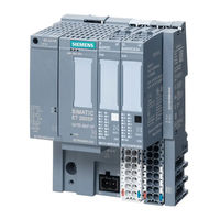
Siemens SIMATIC ET 200SP Operating Instructions Manual (118 pages)
Industrial Ethernet
Brand: Siemens
|
Category: Industrial Electrical
|
Size: 4.05 MB
Table of Contents
-
Preface
3
-
Table of Contents
9
-
Application and Functions
13
-
Components of the Product
13
-
Application
13
-
Communications Services
14
-
Telecontrol Communication (CP 1542SP-1 IRC)
16
-
Communication Via SINEMA RC (CP 1542SP-1 IRC, CP 1543SP-1)
18
-
Security Functions (CP 1542SP-1 IRC, CP 1543SP-1)
20
-
Other Services and Properties
23
-
Configuration Limits and Performance Data
24
-
Requirements for Use
27
-
Hardware Requirements
27
-
Software Requirements
28
-
Configuration Examples
28
-
Leds and Connectors
35
-
Leds
35
-
Power Supply
36
-
Connector for the Busadapter
37
-
Installation, Wiring, Commissioning
39
-
Important Notes on Using the Device
39
-
Notes on Use in Hazardous Areas
39
-
Notes on Use in Hazardous Areas According to ATEX / Iecex
41
-
Notes on Use in Hazardous Areas According to UL Hazloc
41
-
General Notices on Use in Hazardous Areas According to FM
42
-
Installing the CP
42
-
Connecting the CP
46
-
Commissioning the CP
47
-
Configuration
49
-
Security Recommendations
49
-
Configuration in STEP 7
53
-
Communication Types (CP 1543SP-1)
55
-
Ethernet Interface
55
-
Ipv6
55
-
Advanced Options
56
-
Access to the Web Server
57
-
Time-Of-Day Synchronization
57
-
DNS Configuration
59
-
Communication with the CPU
59
-
Snmp
61
-
Security (CP 1543SP-1)
62
-
Security User
62
-
Firewall
62
-
Pre-Check of Messages by the MAC Firewall
62
-
Settings for Online Security Diagnostics and Downloading to Station with the Firewall Activated
63
-
Notation for the Source IP Address (Advanced Firewall Mode)
63
-
Firewall Settings for S7 Connections Via a VPN Tunnel
64
-
Log Settings — Filtering of the System Events
64
-
E-Mail Configuration
64
-
Vpn
65
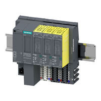
Siemens SIMATIC ET 200SP Equipment Manual (107 pages)
Brand: Siemens
|
Category: Servo Drives
|
Size: 2.05 MB
Table of Contents
-
Preface
4
-
Table of Contents
6
-
ET 200SP Documentation Guide
9
-
-
Wiring
9
-
Maintenance
12
-
Basic Safety Information
14
-
Product Overview
17
-
Area of Application
17
-
Properties
18
-
Supported Functions
20
-
Wiring
21
-
Pin Assignment
21
-
Block Diagram
22
-
Wiring of Multiple F-TM Servodrive
25
-
Connecting the Motor
26
-
Connecting an Encoder
27
-
Connecting IQ-Encoders
27
-
Connecting Safe Torque off (Hardware STO)
28
-
Connecting the 24 V Digital Input
30
-
Connecting an External Braking Resistor
31
-
Safety Functions Integrated in the Drive
33
-
Basic Safety Information
33
-
General Safety Information
33
-
Warranty and Liability for Application Examples
34
-
Fundamental Safety Instructions for Safety Integrated
34
-
Safety Integrated Functions
35
-
Safe Torque off (STO)
37
-
Overview of the Safety Integrated Functions
39
-
Supported Safety Functions
40
-
Examples of Using the Safety Functions
40
-
Safety Concept
41
-
Acceptance of the Safety Functions
41
-
General Information on Acceptance
42
-
Content of an Acceptance Test
45
-
Documentation of Acceptance
45
-
Acceptance Test for Safe Torque off (STO)
47
-
Report Completion
48
-
System Features
48
-
Current Information
48
-
Certifications
49
-
Failure Probability of the Safety Functions
49
-
Response Times
50
-
Safety Integrated
50
-
EMERGENCY off and EMERGENCY STOP
51
-
Configuring
52
-
Communication Telegrams
53
-
Commissioning the
55
-
Basics
56
-
Engineering
56
-
Drive Parameters
57
-
Calling Help Information
59
-
Requirements for the Commissioning
60
-
Commissioning Procedure for the ET 200SP F-TM Servodrive
62
-
Drive Data Sets
63
-
Using the Drive Data Set
65
-
Using Preconfigured Drive Data Sets
66
-
Using a User-Defined Drive Data Set
67
-
Setpoint Channel
68
-
Reference Values
69
-
Application Limits
69
-
Ramp Generator
71
-
Controller Settings
72
-
Open-Loop/Closed-Loop Control
72
-
Filters
74
-
OFF Responses
74
-
Messages/Monitoring
76
-
Motor
77
-
Braking Resistor
77
-
Power End Stage
78
-
Intermediate Circuit Voltage
78
-
Programming
80
-
Controlling F-TM Servodrive Via the Process Image
80
-
Controlling a F-TM Servodrive Via the SINA_SPEED Instruction
87
-
Controlling F-TM Servodrive with a Technology Object
87
-
Maintenance
88
-
Firmware Update
88
-
Stop Responses
88
-
Interrupts, Error Messages and Diagnostics and System Alarms
89
-
Status and Error Displays
89
-
Diagnostics
93
-
Diagnostics Overview of the F-TM Servodrive
93
-
Active Messages
94
-
Drive Diagnostics
95
-
Technical Specifications
98
-
Technical Specifications of the ET 200SP F-TM Servodrive
98
-
Derating of the ET 200SP F-TM Servodrive
102
-
Response Times
103
-
Data Sets
105
-
Index
106
-
Siemens SIMATIC ET 200SP User Manual (112 pages)
open controller
Brand: Siemens
|
Category: Controller
|
Size: 1.82 MB
Table of Contents
-
Preface
4
-
Table of Contents
6
-
1 Documentation Guide
9
-
Documentation on CPU 1515SP PC
11
-
-
2 Safety Notes
12
-
Notes on Use
14
-
-
3 Product Overview
15
-
Properties
15
-
Sample Configuration
17
-
Components
19
-
Configuration of the Devices
20
-
Operator Controls and Display Elements
21
-
Scope of Delivery
24
-
Unpacking the Device
24
-
Scope of Delivery — Hardware Variant WES7 E 32Bit 2GB RAM
26
-
Scope of Delivery — Hardware Variant WES7 P 64Bit 4GB RAM
27
-
-
4 Installing
28
-
Basics
28
-
Hardware Configuration
31
-
Installing the CPU 1515SP PC
32
-
-
5 Connection
34
-
Notes on Connection
34
-
Terminal and Block Diagram
35
-
Electrical Configuration
36
-
Connecting Devices to Networks
37
-
Securing Cables
37
-
-
6 Diagnostics, Error and System Alarm
39
-
Status and Error Display
39
-
-
7 Commissioning
42
-
Notes on Commissioning
42
-
Initial Commissioning
43
-
Installing License Keys
44
-
Windows Security Center
46
-
Switching On/Off the CPU 1515SP PC
47
-
-
8 Functions
48
-
Monitoring Functions
48
-
Retentive Memory NVRAM
49
-
BIOS Description
50
-
Introduction
50
-
Starting BIOS Setup
51
-
BIOS Setup Menus
52
-
Information Menu
54
-
Main Menu
55
-
Advanced Menu
56
-
Security Menu
58
-
Power Menu
59
-
Boot Menu
60
-
Exit Menu
62
-
BIOS Setup Default Settings
63
-
BIOS Update
64
-
Power Options
65
-
Protective Functions for Data Carriers
66
-
Enhanced Write Filter (EWF)
67
-
File-Based Write Filter (FBWF)
71
-

Siemens SIMATIC ET 200SP Manual (98 pages)
Base Unit
Brand: Siemens
|
Category: Control Unit
|
Size: 2.72 MB
Table of Contents
-
Preface
4
-
Table of Contents
5
-
Baseunits (6ES7193-6BP…/3RK1908-0AP00 Manual, 12/2016, A5E03727049-AG
7
-
-
1 Guide to the Documentation
8
-
2 Product Overview
11
-
3 Baseunits for I/O Modules
15
-
BU15-P16+A10+2D (BU Type A0)
15
-
Product Overview
15
-
Connecting up
17
-
Technical Specifications
18
-
BU15-P16+A0+2D (BU Type A0)
19
-
Product Overview
19
-
Connection
21
-
Technical Specifications
22
-
BU15-P16+A10+2B (BU Type A0)
23
-
Product Overview
23
-
Connection
25
-
Technical Specifications
26
-
BU15-P16+A0+2B (BU Type A0)
27
-
Product Overview
27
-
Connection
28
-
Technical Specifications
29
-
BU15-P16+A0+12D/T (BU Type A1)
30
-
Product Overview
30
-
Connection
32
-
Technical Specifications
33
-
BU15-P16+A0+2D/T (BU Type A1)
34
-
Product Overview
34
-
Connection
36
-
Technical Specifications
37
-
BU15-P16+A0+12B/T (BU Type A1)
38
-
Product Overview
38
-
Connection
40
-
Technical Specifications
41
-
BU15-P16+A0+2B/T (BU Type A1)
42
-
Product Overview
42
-
Connection
44
-
Technical Specifications
45
-
BU20-P12+A4+0B (BU Type B0)
46
-
Product Overview
46
-
Connecting
47
-
Technical Specifications
48
-
BU20-P12+A0+4B (BU Type B1)
49
-
Product Overview
49
-
Connecting up
50
-
Technical Specifications
51
-
BU20-P6+A2+4D (BU Type C0)
52
-
Product Overview
52
-
Connecting
54
-
Technical Specifications
55
-
BU20-P6+A2+4B (BU Type C1)
56
-
Product Overview
56
-
Connecting
58
-
Technical Specifications
59
-
BU20-P12+A0+0B (BU Type D0)
60
-
Product Overview
60
-
Connecting
62
-
Technical Specifications
63
-
BU20-P8+A4+0B (BU Type F0)
64
-
Product Overview
64
-
Connecting up
66
-
Technical Specifications
67
-
Siemens SIMATIC ET 200SP Manual (108 pages)
Fail-safe Modul F-CM AS-i Safety ST
3RK7136-6SC00-0BC1
Brand: Siemens
|
Category: Control Unit
|
Size: 1.67 MB
Table of Contents
-
Contents
3
-
Preface
4
-
ET 200SP Distributed I/O System
4
-
Table of Contents
5
-
-
1 Documentation Guide
7
-
Introduction
7
-
-
2 Safety Instructions
9
-
3 Product Overview
13
-
Properties of the F-CM AS-I Safety ST
13
-
Product Overview
14
-
Operating Modes of the F-CM AS-I Safety ST
16
-
Standard Mode
16
-
Error Statuses
17
-
Serious Device Fault
18
-
Device Fault
19
-
Process Signal Error
20
-
Parameter Assignment Error
23
-
Firmware Update
24
-
-
4 Connection
27
-
Terminal Assignment
27
-
Schematic Circuit Diagram
31
-
-
5 Configuring
33
-
Configuring the F-CM AS-I Safety ST
33
-
Safety-Related Communication with AS-Interface
35
-
Operating Principle of Code Sequences of Safe AS-I Slaves
35
-
Operating Principle of the Safe AS-I Outputs
36
-
AS-I Bus Configuration with Multiple F-CM AS-I Safety ST Modules
38
-
Configuring with STEP 7 (Classic)
39
-
Configuring with the TIA Portal
39
-
-
6 Assigning Parameters / Setting the Address Space
41
-
Parameters
41
-
Explanation of the Parameters
44
-
F-Parameters
44
-
Potential Group / AS-I Network
44
-
Module Parameters — General
46
-
Module Parameters — Safe Inputs
46
-
Module Parameters — Safe Outputs
52
-
Address Space
54
-
Address Assignment for User Data and Value Status of the F-CM AS-I Safety ST Module
54
-
Value Status
56
-
Data Records for Diagnostics
57
-
DS 92 Device-Specific Diagnostics
57
-
DS 202 Status Safe Inputs/Outputs
64
-
DS 204 Status Code Sequences
66
-
DS 206 Diagnostic Data Record
69
-
-
7 Code Sequences
75
-
Transferring Code Sequences Via STEP 7 Online Access
76
-
Teach Asisafe Code Sequences» Dialog
76
-
Transferring Code Sequences Via STEP 7 Online Access
77
-
Transferring Taught Code Sequences
80
-
Progress of Teaching Operation» Display
80
-
Transferring Code Sequences with the «TEACH» Button
81
-
Final Steps
82
-
Reintegrating Passivated Input Channels
82
-
Siemens SIMATIC ET 200SP Manual (141 pages)
Technology Module TM PosInput 1
Brand: Siemens
|
Category: Control Unit
|
Size: 1.35 MB
Table of Contents
-
Preface
4
-
Table of Contents
6
-
Technology Module TM Posinput 1 (6ES7138-6BA00-0BA0 Manual, 04/2016, A5E33015755-AC
7
-
-
1 Documentation Guide
8
-
2 Product Overview
11
-
Properties
11
-
Functions
14
-
Acquisition of Encoder Signals
14
-
Position Input with SSI Absolute Encoder
14
-
Counting with Incremental or Pulse Encoder
15
-
Measured Value Determination
17
-
Switching the Outputs at Comparison Values
18
-
Position Input for Motion Control
18
-
Fast Mode
19
-
Fast Mode with SSI Absolute Encoder
20
-
Fast Mode with Incremental or Pulse Encoder
21
-
Additional Functions
23
-
-
3 Wiring
25
-
Pin Assignment
25
-
-
4 Configuring/Address Space
33
-
Configuring
33
-
Reaction to CPU STOP
36
-
Address Space
37
-
Parameters
38
-
Control and Feedback Interface
48
-
Assignment of the Control Interface
49
-
Assignment of the Feedback Interface
51
-
Assignment of the Feedback Interface in Fast Mode
52
-
-
5 Interrupts/Diagnostic Messages
54
-
Status and Error Displays
54
-
Parameter Validation Error
57
-
Error Codes
58
-
Diagnostic Messages
62
-
Interrupts
65
-
Trigger a Diagnostic Interrupt
65
-
Cause of the Error Triggering a Diagnostic Interrupt
66
-
Triggering of a Hardware Interrupt
67
-
Events Which Can Trigger a Hardware Interrupt
68
-
-
6 Technical Specifications
69
Siemens SIMATIC ET 200SP Function Manual (125 pages)
Diagnostics
Brand: Siemens
|
Category: Control Unit
|
Size: 5.93 MB
Table of Contents
-
Preface
4
-
Table of Contents
9
-
1 Function Manuals Documentation Guide
11
-
2 Overview of System Diagnostics
13
-
Properties of System Diagnostics
13
-
Benefits of Innovative System Diagnostics
15
-
-
3 Quick Start
16
-
Using the Display of the CPU
17
-
Using STEP 7
19
-
-
4 Setting and Determining System Diagnostics
24
-
Configuring Alarms for System Diagnostics
24
-
Options for Displaying System Diagnostics
26
-
Diagnostics Information at the Devices
27
-
Leds
27
-
Display of the CPU
28
-
Diagnostics Information in STEP 7
30
-
Explanation of Diagnostics Symbols
30
-
Accessible Devices (Without Project)
32
-
Devices & Networks
34
-
Online & Diagnostics
37
-
Diagnostics» Tab in the Inspector Window
40
-
CPU Diagnostics Buffer
43
-
Online Tools» Task Card
46
-
Configuring the Settings for I/O Modules in STEP 7
48
-
Diagnostics Information Using the Web Server
49
-
Diagnostics Information Using the HMI Diagnostics View
60
-
Configuring System Diagnostics
61
-
Different Views of the HMI Diagnostics View
64
-
Inserting System Diagnostics Indicator
67
-
Configuring Button as System Diagnostics Indicator
69
-
-
5 System Diagnostics by Means of the User Program
72
-
Options of System Diagnostics in the User Program
72
-
System Diagnostics Using Process Image Inputs
74
-
-
6 Alarms
77
-
Creating Alarms with the «Program_Alarm» Instruction
78
-
Editing Alarms in the Alarm Editor
79
-
Display of Program Alarms
82
-
Output of the Alarm State with the «Get_Alarmstate» Instruction
83
-
Example Program for Program Alarms
84
-
Task
84
-
Example 1: Program Alarm Without Associated Values
85
-
Example 2: Program Alarm with Associated Value
90
-
Displaying the Alarm
97
-
-
7 Diagnostics of the S7-1500R/H Redundant System
98
-
Online and Diagnostics View
101
-
Online Tools» Task Card
104
-
Diagnostics View in the Project Tree and in the Device View and Network View
107
-
Diagnostics in the RUN-Redundant System State
112
-
Restrictions in the RUN-Solo System State
118
-
System Diagnostics by Means of the User Program
119
-
Glossary
120
-
Index
124
-
Siemens SIMATIC ET 200SP Manual (109 pages)
Analog input module AI Energy Meter 400VAC ST 6ES7134-6PA01-0BD0
Brand: Siemens
|
Category: I/O Systems
|
Size: 3.17 MB
Table of Contents
-
Preface
4
-
Table of Contents
6
-
1 Documentation Guide
8
-
2 Product Overview
12
-
Area of Application
12
-
Properties of the AI Energy Meter 400VAC ST
14
-
-
3 Wiring
16
-
Terminal and Block Diagram
16
-
Connection Examples
19
-
Current Transformer Selection Data
20
-
-
4 Configuration / Address Space
23
-
Configuring
23
-
Selecting the Module Versions
24
-
Changing over the User Data Variant During Operation
25
-
Recommendations for Selecting the Module Version
26
-
Applicable Modules
27
-
-
5 Quick Start
28
-
6 Reading and Processing Measured Values
30
-
Basics for Reading Measured Values
30
-
Quality Information
32
-
Reading Measured Values from User Data Cyclically
34
-
Read Measured Value from a Measured Value Data Record
36
-
-
7 Energy Counters
37
-
How the Energy Meter Works
37
-
Configuring Counters
39
-
Evaluating Energy Counters
41
-
Reset Energy Counter
42
-
Introduction
42
-
Reset Energy Counters Via User Data
42
-
Resetting Energy Counters Via Data Record DS 143
44
-
Example for Resetting Energy Counters Via Data Record DS 143
46
-
Data Record for Energy Counter (DS 143)
49
-
Structure for Energy Counters (DS 143)
49
-
Structure of the Control and Feedback Interface for DS 143
52
-
-
8 Parameters
54
-
Description of Parameters
57
-
-
9 Interrupts/Diagnostic Alarms
61
-
Status and Error Display
61
-
Interrupts
63
-
Diagnostics Interrupt
63
-
Diagnostic Alarms
64
-
Diagnostics Response
65
-
-
10 Technical Specifications
66
-
Parameter Data Records
72
-
Configuration Via Parameter Data Records
72
-
Structure of the Parameter Data Record 128 for the Entire Module
73
-
-
Measured Variables
80
-
Module Versions
85
-
Module Version «2 I / 2 Q
85
-
C.1 Module Version «2 I / 2 Q»
85
-
Module Version «32 I / 12 Q
88
-
-
User Data Variants
92
-
User Data Variants with 32 Bytes Input Data / 12 Bytes Output Data
92
-
-
Measured Value Data Records
103
-
Overview of All Measured Value Data Records
103
-
Measured Value Data Record for Base Measurements (DS 142)
104
-
Structure for Energy Counters (DS 143)
106
-
-
Tips and Tricks
109
-

Siemens SIMATIC ET 200SP Equipment Manual (90 pages)
Brand: Siemens
|
Category: I/O Systems
|
Size: 1.97 MB
Table of Contents
-
Preface
5
-
Table of Contents
7
-
1 Documentation Guide
9
-
ET 200SP Documentation Guide
9
-
-
2 Product Overview
14
-
Properties
14
-
Functions
16
-
Safety
16
-
Detection of Counting Signals
17
-
Measured Value Determination
18
-
Counter Control and Feedback
21
-
Counter Input Diagnostics
22
-
-
3 Connecting
25
-
Wiring and Block Diagram
25
-
-
4 Parameters/Address Space
30
-
Configuring the F-TM Count Module
30
-
Using STEP 7 (TIA Portal V17 or Greater)
31
-
Using STEP 7 (TIA Portal) with GSDML (Versions of TIA Portal Prior to V17)
32
-
Reinitialize on Parameterization Download
34
-
Reaction to CPU STOP
35
-
Reactions to Counting Limit Violation
35
-
Parameters of the F-TM Count
36
-
Explanation of Parameters
38
-
F-Parameters
38
-
TM-C Parameters
40
-
Behavior at the Counting Limits
49
-
Quadrature Evaluation of Differential Signals
51
-
Safety Functions
52
-
Safe Operating Stop (SOS)
52
-
Function of SOS
54
-
Example Using SOS Monitoring
55
-
Configuring SOS
55
-
Enabling SOS
55
-
Responding to SOS
55
-
Safety Limited Speed (SLS)
56
-
Function of Safety Limited Speed (SLS)
57
-
Configuring SLS
58
-
Enabling SLS
58
-
Responding to SLS
58
-
Safe Direction (SDI)
59
-
Function of Safe Direction (SDI)
61
-
Configuring SDI
61
-
Responding to SDI
62
-
Address Space
62
-
Control and Feedback Interface
63
-
Assignment of the Control Interface
63
-
Assignment of the Feedback Interface
65
-
-
5 Applications of the F-I/O Module
68
-
Application Mode 1: A/B with N
68
-
Application Mode 2: A/B Without N
69
-
Siemens SIMATIC ET 200SP Manual (83 pages)
Technology module TM ECC PL ST
Brand: Siemens
|
Category: I/O Systems
|
Size: 1.39 MB
Table of Contents
-
ET 200SP Documentation
3
-
Preface
5
-
Table of Contents
7
-
1 ET 200SP Documentation Guide
9
-
2 Product Overview
13
-
Properties
13
-
Control Pilot
18
-
Plug Present
20
-
Charge Communication
22
-
Session Setup
23
-
Service Discovery
24
-
Service and Payment Selection
24
-
Contract Authentication
24
-
Charge Parameter Discovery
24
-
Cable Check
25
-
Pre Charge
25
-
Power Delivery
26
-
Current Demand
27
-
Welding Detection
27
-
Session Stop
28
-
-
3 Wiring
29
-
Terminal Assignment and Power Supply
29
-
Connection Examples
34
-
Installation Instruction
35
-
-
4 Configuring/Address Space
37
-
Configuring
37
-
Reaction to CPU STOP
38
-
Required I/O Address Space
38
-
Parameter
38
-
Control and Feedback Interface
39
-
Assignment of the Control Interface
39
-
Assignment of the Feedback Interface
39
-
-
5 Programming
41
-
General Information
41
-
DIN_70121″ Function Block
41
-
Required Memory of the Function Block DIN_70121
42
-
Principle of Operation of the DIN_70121 Function Block
42
-
Startup Characteristics of the Function Block
42
-
Response to Errors
43
-
Possible Circuitry of a Frequency Converter
43
-
Authentication Phase
44
-
Parameter Discovery» Phase
45
-
Checking Safe Isolation from Supply on the Charging Cable (External Voltage Check)
46
-
Carrying out the Cable Check
47
-
Carrying out the Voltage Equalization of the Frequency Converter (Precharge)
50
-
Implementation of the Powerdelivery Phase (Start Charging)
50
-
Execution of the Charge Process (Current Demand)
51
-
Termination of the Charging Process
52
-
Hardware States
53
-
DIN_70121 Parameter
55
-
Udt_Charger_In
55
-
Udt_Charger_Evsecfg
56
-
Udt_Charger_Values
60
-
Udt_Charger_Out
62
-
Udt_Charger_Ev
64
-
Udt_Charger_Ev_Diagnostics
65
-
Udt_Charger_Ev_Limits
66
-
Udt_Charger_Setpoints
67
-
Error Messages
68
-
Siemens SIMATIC ET 200SP Manual (106 pages)
Technology module, TM Count 1x24V
Brand: Siemens
|
Category: Industrial Electrical
|
Size: 0.93 MB
Table of Contents
-
Preface
4
-
Table of Contents
6
-
Documentation Guide
8
-
Product Overview
13
-
Properties
13
-
Functions
18
-
Detection of Counting Signals
18
-
Measured Value Determination
19
-
Switching the Outputs at Comparison Values
19
-
Position Input for Motion Control
20
-
Fast Mode
20
-
Additional Functions
21
-
Wiring
22
-
Pin Assignment and Block Diagram
22
-
Configuring/Address Space
27
-
Operating with «Counting and Measurement» Technology Object
27
-
Configuring
27
-
Reaction to CPU STOP
28
-
Parameter Setting
28
-
Address Space
33
-
Isochronous Mode
33
-
Position Input for «»Motion Control»» Technology Object
34
-
Configuring
34
-
Parameter Setting
35
-
Address Space
37
-
Control Interface and Feedback Interface
37
-
Assignment of the Control Interface
37
-
Configuring
37
-
Configuring
39
-
Reaction to CPU STOP
41
-
Parameter Setting
42
-
Explanation of Parameters
46
-
Address Space
47
-
Assignment of the Feedback Interface
50
-
Isochronous Mode
54
-
Interrupts/Diagnostic Messages
75
-
Status and Error Display
75
-
Diagnostic Messages
78
-
Hardware Interrupts
82
-
Technical Specifications
84
-
Parameter Data Record
93
-
A.1 Parameter Assignment and Structure of Parameter Data Record
94
-
Parameter Validation Error
103

Siemens SIMATIC ET 200SP Manual (96 pages)
HA Input/output module AI-DI 16/DQ16x24VDC HART HA
Brand: Siemens
|
Category: I/O Systems
|
Size: 0.68 MB
Table of Contents
-
Table of Contents
3
-
1 Security Information
5
-
2 Product Overview
7
-
Properties of the I/O Module AI-DI 16/Dq16X24Vdc HART HA
7
-
-
3 Wiring
11
-
Pin Assignment of the I/O Module AI-DI 16/Dq16X24Vdc HART HA
11
-
Schematic Circuit Diagram
15
-
-
4 Parameters
17
-
Configurations of the I/O Module AI-DI 16/Dq16X24Vdc HART HA
17
-
Module/Channel Parameters
18
-
Explanation of the Module/Channel Parameters
23
-
Explanation of the Digital Output Parameters
24
-
Explanation of the Digital Input Parameters
25
-
Explanation of the Analog Input Parameters
27
-
HART Mapping Parameters
30
-
-
5 Displays and Interrupts
31
-
Status and Error Displays of the I/O Module AI-DI 16/Dq16X24Vdc HART HA
31
-
Interrupts
33
-
-
6 HART Function
35
-
How HART Works
36
-
HART Applications
40
-
HART Variables
42
-
-
7 Technical Specifications
45
-
Drivers, Parameters, Diagnostics Messages and Address Space
53
-
Concept of the Driver and Diagnostics Blocks
53
-
Parameter Assignment
55
-
A.2 Parameter Assignment
55
-
A.3 Parameter Assignment and Structure of the Module and Channel Parameters
57
-
Parameter Assignment and Structure of HART Mapping Parameters DS 130
64
-
Diagnostics Messages and Maintenance Events
66
-
Hardware Interrupts
70
-
A.6 Hardware Interrupts
70
-
Address Space in Digital Mode
72
-
Address Space in Digital Mode with Time Stamp (Accuracy 1 Ms)
73
-
Address Space in Mixed Mode
74
-
-
HART Operating Data Records
79
-
HART Command Interface
79
-
HART Job and Response Data Records
81
-
HART Directory
87
-
B.3 HART Directory
87
-
HART Feature Data
88
-
HART Variable Data Record
89
-
HART-Specific Settings
90
-
-
Analog Value Display
93
-
Representation of Analog Values in the Current Measuring Ranges
93
-
Index
95
-
-
Siemens SIMATIC ET 200SP Manual (84 pages)
Digital input module
Brand: Siemens
|
Category: Control Unit
|
Size: 2.58 MB
Table of Contents
-
Preface
4
-
Table of Contents
6
-
1 Documentation Guide
8
-
2 Product Overview
12
-
Properties
12
-
-
3 Operating Mode DI
16
-
Wiring up
16
-
Wiring and Block Diagrams
16
-
Parameters/Address Space
19
-
High-Speed Inputs
19
-
Parameters
20
-
Explanation of Parameters
22
-
Address Space
25
-
Interrupts/Diagnostics Alarms
26
-
Status and Error Display
26
-
Interrupts
29
-
Diagnostics Alarms
31
-
-
4 Counting Operating Mode (CNT)
32
-
Connecting
32
-
Wiring and Block Diagrams
32
-
Parameters/Address Space
35
-
Counting
35
-
Parameters
37
-
Explanation of Parameters
39
-
Address Space
43
-
Assignment of the Control Interface
43
-
Assignment of the Feedback Interface
45
-
Interrupts/Diagnostic Messages
49
-
Status and Error Display
49
-
Interrupts
52
-
Diagnostics Alarms
53
-
-
5 Oversampling (OVS) Operating Mode
54
-
Connecting
54
-
Wiring and Block Diagrams
54
-
Parameters/Address Space
57
-
Oversampling
57
-
Parameters
59
-
Explanation of Parameters
61
-
Address Space
62
-
Interrupts/Diagnostic Messages
63
-
Status and Error Display
63
-
Interrupts
66
-
Diagnostics Alarms
67
-
-
6 Technical Specifications
68
-
Parameter Data Records
72
-
Parameter Assignment and Structure of Parameter Data Record for DI Operating Mode
72
-
Parameter Assignment and Structure of Parameter Data Record for Counting Operating Mode
76
-
Parameter Assignment and Structure of Parameter Data Record for Oversampling Operating Mode
81
-
-

Siemens SIMATIC ET 200SP Manual (69 pages)
BusAdapter
Brand: Siemens
|
Category: Adapter
|
Size: 1.77 MB
Table of Contents
-
Table of Contents
4
-
1 Preface
6
-
2 Guide
9
-
Busadapter Guide
9
-
-
3 Product Overview
12
-
4 Busadapter BA 2Xrj45
15
-
Product Overview
15
-
Connecting
16
-
Diagnostics
19
-
Technical Specifications
20
-
-
5 Busadapter BA 2Xfc
21
-
Product Overview
21
-
Connecting
22
-
Diagnostics
26
-
Technical Specifications
27
-
-
6 Busadapter BA 2Xscrj
28
-
Product Overview
28
-
Connecting
29
-
Diagnostics
33
-
Technical Specifications
35
-
-
7 Busadapter BA SCRJ/RJ45
36
-
Product Overview
36
-
Connecting
37
-
Diagnostics
39
-
Technical Specifications
41
-
-
8 Busadapter BA SCRJ/FC
42
-
Product Overview
42
-
Connecting
43
-
Diagnostics
45
-
Technical Specifications
47
-
-
9 Busadapter BA 2Xlc
48
-
Product Overview
48
-
Connecting
49
-
Diagnostics
53
-
Technical Specifications
54
-
-
10 Busadapter BA LC/RJ45
55
-
Product Overview
55
-
Connecting
56
-
Diagnostics
58
-
Technical Specifications
59
-
-
11 Busadapter BA LC/FC
60
-
Product Overview
60
-
Connecting
61
-
Diagnostics
63
-
Technical Specifications
64
-
-
12 Strain Relief
65
-
Product Overview
65
-
Installing
66
-
Dimension Drawings
68
-
Busadapter Dimension Drawings
68
-
Strain Relief Dimension Drawings
68
-
-
Accessories
69
-
B.1 Accessories
69
-
Siemens SIMATIC ET 200SP Manual (49 pages)
CPU 1512SP-1 PN 6ES7512-1DK01-0AB0
Brand: Siemens
|
Category: Control Unit
|
Size: 1.66 MB
Table of Contents
-
Contents
2
-
Proper Use of Siemens Products
3
-
Qualified Personnel
3
-
Warning Notice System
3
-
Security Information
4
-
Preface
4
-
Table of Contents
6
-
1 Documentation Guide
7
-
Manual Collection ET 200SP
8
-
«Mysupport»
8
-
«Mysupport» — Documentation
8
-
General Information
8
-
«Mysupport» — Cax Data
9
-
Application Examples
9
-
TIA Selection Tool
9
-
SIMATIC Automation Tool
10
-
Proneta
10
-
-
2 Product Overview
11
-
New Functions in Firmware Version V2.0
11
-
Operating Principle
14
-
IO Controller
14
-
I-Device
14
-
Standalone CPU
14
-
-
Properties
15
-
Article Number
15
-
View of the Module
15
-
Integrated Web Server
17
-
Integrated Technology
17
-
Motion Control
17
-
Integrated Closed-Loop Control Functionality
17
-
Trace Functionality
18
-
Integrated System Diagnostics
18
-
Integrated Security
18
-
Support for ET 200AL
18
-
Address Space
19
-
-
Operating and Display Elements
20
-
Front View of the Module with Busadapter
20
-
Mode Switch
21
-
Mode Switch Settings
21
-
-
3 Wiring
22
-
24 V DC Supply Voltage (X80)
22
-
PROFINET IO Interface on the CPU (X1 P3)
22
-
Supply Voltage Connection
22
-
Pin Assignment PROFINET IO Interface on the Busadapter BA 2Xrj45
23
-
Pin Assignment PROFINET IO Interface on the Busadapter BA 2Xfc
24
-
Pin Assignment PROFINET IO with Busadapter BA 2×LC
24
-
Pin Assignment PROFINET IO with Busadapter BA LC/RJ45
25
-
PROFINET IO Pin Assignment with Busadapter BA LC/FC
25
-
PROFINET IO Pin Assignment with Busadapter BA 2×SCRJ
26
-
Pin Assignment PROFINET IO with Busadapter BA SCRJ/RJ45
26
-
PROFINET IO Pin Assignment with Busadapter BA SCRJ/FC
27
-
Assignment of the MAC Addresses
27
-
Block Diagram
29
-
Block Diagram of the CPU 1512SP-1 PN
29
-

Siemens SIMATIC ET 200SP Manual (72 pages)
Analog output module AQ 4xI HART HF (6ES7135-6TD00-0CA1)
Brand: Siemens
|
Category: Control Unit
|
Size: 0.54 MB
Table of Contents
-
Preface
5
-
Table of Contents
7
-
1 Documentation Guide
9
-
2 Product Overview
11
-
Properties
11
-
-
3 Wiring up
13
-
Connection and Block Diagram
13
-
-
4 HART Function
17
-
How HART Works
18
-
Use of HART
22
-
HART Communication Interface
24
-
HART Variables
26
-
-
5 Parameters
29
-
Parameters of AQ 4Xi HART
29
-
Channel/Technology Parameters
29
-
Explanation of the Channel/Technology Parameters
31
-
HART Mapping Parameters
34
-
-
6 Configuring/Address Space
37
-
Configuring
37
-
Address Space
38
-
-
7 Interrupts/Diagnostics Alarms
41
-
Status and Error Displays
41
-
Interrupts
43
-
Diagnostics Alarms
44
-
-
8 Technical Specifications
47
-
Technical Specifications of the AQ 4Xi HART
47
-
Standards and Approvals
50
-
Currently Valid Markings and Approvals
50
-
ATEX Approval
52
-
Iecex Approval
53
-
FM Approval
53
-
-
Appendix
55
-
Parameter Data Records
55
-
Parameter Assignment and Structure of the Channel/Technology Parameters
55
-
A.1 Parameter Data Records
55
-
Parameter Assignment and Structure of the HART Mapping Parameters
57
-
HART Operating Data Records
59
-
HART Directory
59
-
HART Feature Data
60
-
HART Variable Data Record
60
-
HART-Specific Settings
61
-
HART Request and Response Data Records
62
-
Example of HART Programming (HART Command Interface)
65
-
Analog Value Display
68
-
Analog Value Display in the Current Output Range 0 to 20 Ma
68
-
Analog Value Display in the Current Output Range 4 to 20 Ma
68
-
Contact
70
-
A.4 Contact
70
-
Index
71
-

Siemens SIMATIC ET 200SP Manual (83 pages)
Brand: Siemens
|
Category: I/O Systems
|
Size: 4.87 MB
Table of Contents
-
Preface
4
-
Table of Contents
6
-
1 Documentation Guide
7
-
2 Product Overview
11
-
Properties
11
-
Functions
14
-
Detection of Counting Signals
14
-
Measured Value Determination
16
-
Switching the Outputs at Comparison Values
17
-
Position Input for Motion Control
17
-
Fast Mode
18
-
Additional Functions
20
-
-
3 Wiring
22
-
Pin Assignment
22
-
-
4 Configuring/Address Space
28
-
Configuring
28
-
Reaction to CPU STOP
31
-
Address Space
32
-
Parameters
33
-
Parameter Setting
33
-
Parameters for Operating with Technology Object «Counting and Measurement
36
-
Parameters for Position Input for «Motion Control» Technology Object
41
-
Parameters for Manual Operation (Without Technology Object)
43
-
Parameters for Operating in Fast Mode
48
-
Control and Feedback Interface
52
-
Assignment of the Control Interface
53
-
Assignment of the Feedback Interface
55
-
Assignment of the Feedback Interface in Fast Mode
56
-
-
5 Interrupts/Diagnostic Messages
57
-
Status and Error Displays
57
-
Diagnostic Messages
60
-
Hardware Interrupts
64
-
-
6 Technical Specifications
66
-
Parameter Data Record
73
-
Parameter Assignment and Structure of the Parameter Data Record
73
-
Parameter Validation Error
81
-
-

Siemens SIMATIC ET 200SP Manual (76 pages)
Analog input module AI 2xSG 4-/6-wire HS
Brand: Siemens
|
Category: Control Unit
|
Size: 1.64 MB
Table of Contents
-
Preface
5
-
Table of Contents
7
-
1 Safety Instructions
9
-
2 Documentation Guide
11
-
3 Product Overview
15
-
4 Mounting
17
-
Safety Notices for Installation
17
-
Safety Information According to FM and UL
18
-
Mounting on the SIMATIC ET 200SP
19
-
-
5 Connecting
21
-
Wiring and Block Diagram
21
-
-
6 Parameters/Address Space
25
-
Measurement Types and Measuring Ranges
25
-
Parameters
26
-
Description of Parameters
28
-
Oversampling
30
-
Address Space
33
-
Input Lock
37
-
-
7 Interrupts/Diagnostics Interrupts
39
-
Status and Error Displays
39
-
Interrupts
41
-
Diagnostics Alarms
43
-
-
8 Service and Maintenance
45
-
Basic Safety Instructions
45
-
-
9 Technical Specifications
47
-
Mechanical Requirements and Data
50
-
Electrical, EMC and Climatic Requirements
51
-
Approvals
55
-
-
10 Accessories
57
-
Baseunit Type A0 (Essential)
57
-
Parameter Data Record
59
-
Dependencies When Configuring with GSD File
59
-
-
Parameter Assignment
60
-
Parameter Data Record 128
61
-
Parameter Data Records 0 and 1
66
-
Parameters Specifications
70
-
Representation of Analog Values
71
-
Representation of Analog Values for Analog Inputs
71
-
Representation of the Input Range
72
-
Analog Value Representation
73
-
Index
75
-

Siemens SIMATIC ET 200SP Equipment Manual (69 pages)
Brand: Siemens
|
Category: I/O Systems
|
Size: 2.9 MB
Table of Contents
-
Preface
4
-
Table of Contents
7
-
1 Documentation Guide
14
-
2 Product Overview
14
-
Properties
14
-
-
3 Connecting
17
-
Wiring and Block Diagram
17
-
-
4 Parameters/Address Space
19
-
Parameters
19
-
Explanation of Parameters
22
-
F-Parameters
22
-
Behavior after Channel Fault
22
-
Reintegration after Channel Fault
23
-
Parameters of the Sensor Supply
24
-
Short-Circuit Test
24
-
Time for Short-Circuit Test
25
-
Startup Time of Sensor after Short-Circuit Test
25
-
Parameters of the Channel Pairs
26
-
Sensor Evaluation
26
-
Discrepancy Behavior
27
-
Discrepancy Time
28
-
Reintegration after Discrepancy Error
29
-
Parameters of the Channels
30
-
Activated
30
-
Channel Failure Acknowledge
30
-
Sensor Supply
31
-
Input Delay
31
-
Chatter Monitoring
32
-
Number of Signal Changes
33
-
Monitoring Window
33
-
Address Space
33
-
-
5 Applications of the F-I/O Module
35
-
Applications of the Electronic Module
35
-
Application 1: Safety Mode Sil3/Cat.3/Pld
37
-
Application 2: Safety Mode Sil3/Cat.3/Ple
40
-
Application 3: Safety Mode Sil3/Cat.4/Ple
44
-
Application 3.1: Safety Mode Sil3/Cat.4/Ple
45
-
Application 3.2: Safety Mode Sil3/Cat.4/Ple
48
-
-
6 Interrupts/Diagnostic Messages
51
-
Status and Error Display
51
-
Interrupts
54
-
Diagnostic Messages
56
-
Value Status
61
-
-
7 Technical Specifications
63
-
Response Times
67
siemens SIMATIC ET 200SP Function Manual (82 pages)
automation system
Brand: siemens
|
Category: Industrial Equipment
|
Size: 2.04 MB
Table of Contents
-
Preface
4
-
With STEP
4
-
Table of Contents
8
-
-
1 Documentation Guide
9
-
2 Memory Areas and Retentive Memory
14
-
Memory Areas
14
-
The SIMATIC Memory Card
15
-
Specifics of the Cpus of the Redundant System S7-1500R/H
17
-
Memory Requirements and Memory Usage
19
-
Retentive Memory Areas
27
-
Summary of Retentive Behavior
31
-
Retentive Behavior of the Memory Objects
31
-
Memory Behavior When Loading Software Changes
33
-
Memory Requirements for Downloading Software Changes
35
-
-
3 Memory Usage and Application Examples
39
-
Memory Usage for Recipes
39
-
Section Service Life of the
41
-
Memory Usage for Data Logging
44
-
Overview of Data Logging
44
-
Data Structure of the Data Logs
46
-
Instructions for Data Logging
47
-
Example Program for Data Logging
48
-
Calculation of the Data Log Size
54
-
-
4 SIMATIC Memory Card
58
-
SIMATIC Memory Card — Overview
58
-
Setting the Card Type
65
-
Data Transfer with SIMATIC Memory Cards
66
-
Service Life of the SIMATIC Memory Card
69
-
Expanding the Load Memory of the Cpus of the Redundant System S7-1500R/H
74
-
Glossary
75
-
Index
81
-

Siemens SIMATIC ET 200SP Function Manual (79 pages)
Cycle and response times
Brand: Siemens
|
Category: Controller
|
Size: 2.27 MB
Table of Contents
-
Preface
4
-
Table of Contents
8
-
1 Documentation Guide
9
-
2 Program Execution
14
-
Principle of Operation
14
-
Overload Behavior
17
-
-
3 Cyclic Program Execution
21
-
Cycle
22
-
Cycle Time
25
-
Different Cycle Times
25
-
Influences on the Cycle Time
29
-
Update Time for Process Image Partitions
29
-
User Program Execution Time
32
-
Extension of Cycle Time Due to Communication Load
37
-
Special Consideration When PROFINET IO Communication Is Configured on the 2Nd PROFINET Interface (X2)
39
-
Time-Driven Program Execution in Cyclic Interrupts
41
-
Response Time for Cyclic and Time-Driven Program Execution
43
-
Summary of Response Time with Cyclic and Time-Controlled Program Execution
46
-
-
4 Event-Driven Program Execution
48
-
Response Time of the Cpus When Program Execution Is Event-Controlled
48
-
Process Response Time When Program Execution Is Event-Driven
50
-
-
5 Cycle and Response Times of the S7-1500R/H Redundant System
52
-
Introduction
52
-
Maximum Cycle Time and Time Errors
53
-
5.3 Influences on the Cycle Time of the S7-1500R/H Redundant System
55
-
Influences on the Cycle Time in RUN-Solo System State
55
-
Influences on the Cycle Time in SYNCUP System State
56
-
Influences on the Cycle Time in RUN-Redundant System State
60
-
Influences on the Cycle Time When a CPU Fails
64
-
Response Time of R/H Cpus
67
-
Timetables for the RUN-Redundant System State
70
-
Glossary
73
-
Index
78
-
Siemens SIMATIC ET 200SP Manual (80 pages)
Analog input module
Brand: Siemens
|
Category: Control Unit
|
Size: 2.24 MB
Table of Contents
-
Preface
4
-
Table of Contents
6
-
1 Guide to Documentation
7
-
2 Product Overview
12
-
Properties
12
-
-
3 Wiring
15
-
Wiring and Block Diagram
15
-
-
4 Parameters/Address Space
18
-
Measurement Types and Measuring Ranges
18
-
Parameters
22
-
Explanation of Parameters
28
-
Scalable Measuring Range
33
-
Configuration
35
-
Evaluating Data Record 235
36
-
Address Space
39
-
-
5 Interrupts/Diagnostics Alarms
40
-
Status and Error Display
40
-
Interrupts
42
-
Diagnostics Alarms
44
-
-
6 Technical Specifications
46
-
Parameter Data Record
54
-
Dependencies When Configuring with GSD File
54
-
Parameter Assignment and Structure of Parameter Data Record
60
-
Errors When Transferring the Data Record
68
-
Switchable Wire Break Check
69
-
-
Representation of Analog Values
70
-
Representation of Input Ranges
71
-
Representation of Analog Values in Voltage Measuring Ranges
72
-
Representation of Analog Values for Resistance-Type Sensors
73
-
Representation of Analog Values for Thermal Resistors
74
-
Representation of Analog Values for Thermocouples
77
-
-
Siemens SIMATIC ET 200SP System Manual (68 pages)
Motor Starter
Brand: Siemens
|
Category: Controller
|
Size: 2.72 MB
Table of Contents
-
Preface
5
-
Table of Contents
7
-
1 Documentation Guide
9
-
2 System Overview
13
-
What Is the SIMATIC ET 200SP Distributed I/O System
13
-
Components
16
-
Datamatrix Code
19
-
3DI/LC Module
20
-
-
3 Application Planning
25
-
Installation Conditions
25
-
Selecting the Motor Starter
26
-
Designing Interference-Free Motor Starters
27
-
Selecting Accessories
28
-
Selecting the Baseunit
31
-
-
4 Mounting
35
-
Assembling/Disassembling the Motor Starter
35
-
Mounting the Fan
40
-
Mounting the Cover for the 500 V AC Infeed Bus
41
-
Mounting the Mechanical Bracket for the Baseunit
42
-
-
5 Connecting
45
-
Wiring Rules
45
-
Wiring Baseunits
46
-
Protection against Short Circuit
48
-
500 V AC Infeed Bus
48
-
-
6 Configuration
49
-
Configuration Control
49
-
-
7 Commissioning
51
-
8 Maintenance
53
-
Introduction
53
-
Maintenance and Repair
53
-
Warranty
53
-
-
9 Technical Specifications
55
-
Electromagnetic Compatibility
55
-
Declaration of Conformity
56
-
-
10 Dimension Drawings
57
-
3DI/LC Module
58
-
Fan
58
-
Labeling Strip
59
-
Reference Identification Labels
60
-
-
11 Accessories/Spare Parts
61
-
ESD Guidelines
63
-
Glossary
65
-
-

Siemens SIMATIC ET 200SP Manual (77 pages)
Analog Input Module AI 8xRTD/TC 2-wire HF 6ES7134-6ES7134-6JF00-0CA1
Brand: Siemens
|
Category: I/O Systems
|
Size: 2.35 MB
Table of Contents
-
Preface
4
-
Table of Contents
6
-
1 Guide to Documentation
7
-
2 Product Overview
12
-
Properties
12
-
-
3 Wiring
15
-
Wiring and Block Diagram
15
-
-
4 Parameters/Address Space
18
-
Measurement Types and Measuring Ranges
18
-
Parameters
22
-
Explanation of Parameters
27
-
Scalable Measuring Range
32
-
Configuration
34
-
Evaluating Data Record 235
35
-
Address Space
38
-
-
5 Interrupts/Diagnostics Alarms
39
-
Status and Error Displays
39
-
Interrupts
41
-
Diagnostics Alarms
43
-
-
6 Technical Specifications
45
-
Parameter Data Record
53
-
Dependencies When Configuring with GSD File
53
-
Parameter Assignment and Structure of Parameter Data Record
58
-
Errors When Transferring the Data Record
66
-
Switchable Wire Break Check
67
-
-
Representation of Analog Values
68
-
Representation of Input Ranges
69
-
Representation of Analog Values in Voltage Measuring Ranges
70
-
Representation of Analog Values for Resistance-Type Sensors
71
-
Representation of Analog Values for Thermal Resistors
72
-
Representation of Analog Values for Thermocouples
74
-
-
Siemens SIMATIC ET 200SP Function Manual (58 pages)
Brand: Siemens
|
Category: I/O Systems
|
Size: 6.82 MB
Table of Contents
-
Table of Contents
3
-
Legal Information
5
-
About this Documentation
7
-
Additional Documentation
7
-
Purpose of the Documentation
7
-
Target Group
7
-
Required Knowledge
7
-
Introduction
9
-
AS-Interface
9
-
AS-Interface Basics
9
-
Network Structure
10
-
Creating an AS-Interface Network
12
-
Number of Nodes
13
-
Network Extension
14
-
AS-I Safety
15
-
AS-I Safety Product Overview
16
-
Circuit Diagram Example
21
-
Knowledge Required
21
-
Operating Principle
21
-
Overview
21
-
Emergency Stop
24
-
Monitoring the Position of the Protective Door and Tumbler Function
25
-
Control and Monitoring of the Actuator
27
-
Hardware and Software Components
28
-
Validity
28
-
Components Used
28
-
Example of Wiring
29
-
Sample Data and Projects
29
-
TIA Portal Configuration
30
-
TIA Portal Engineering
30
-
Configuration of the ET 200SP Modules CM AS-I Master ST and F-CM AS-I Safety ST
30
-
Configuring ET 200SP System
31
-
Adding AS-I Slaves
34
-
Setting F Parameters
36
-
Configuring Safe AS-I Slave Monitoring
37
-
Minimum Number of Slaves for AS-I Safety Applications
42
-
Assigning Fail-Safe Addresses to ET 200SP
44
-
Teaching Asisafe Code Sequences
45
-
TIA Portal Programming
47
-
Commissioning and Operation
51
-
Commissioning
51
-
Preparation
51
-
Load S7 Project into the CPU
51
-
Assigning Profisafe Addresses
52
-
Using the Application
53
-
Evaluating the Safety Function
54
-
Appendix
55
-
Service and Support
55
-
Links and Literature
57
-
Version History
57
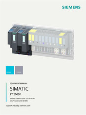
Siemens SIMATIC ET 200SP Manual (50 pages)
Brand: Siemens
|
Category: Industrial Equipment
|
Size: 0.89 MB
Table of Contents
-
Preface
4
-
Table of Contents
6
-
ET 200SP Documentation Guide
8
-
Information Classes ET 200SP
8
-
Basic Tools
10
-
Multifieldbus Configuration Tool (MFCT)
11
-
SIMATIC Technical Documentation
12
-
Product Overview
14
-
Properties
14
-
Functions
18
-
Supported Ethernet Services: ICMP, ARP, SNMP, LLDP
20
-
Port Diagnostics
20
-
Disabling of Ports
20
-
Minimum Update Time 1 Ms
20
-
Device Replacement Without Programming Device (PG) and Without Topological Configuration
21
-
Media Redundancy Protocol (MRP)
22
-
Distribution of Module Channels to a Maximum of 4 Submodules
22
-
Real-Time Communication
22
-
Use of Fail-Safe Modules
23
-
Redundancy Switchover Times for the Fail-Safe Modules
23
-
System Redundancy R1
23
-
Value Status of I/O Modules
23
-
Reading out Service Data
24
-
Reference Temperature Distribution
24
-
H-Sync Forwarding
24
-
Setting the Time
25
-
Time Distribution
25
-
Diagnostic Interrupts
25
-
Hardware Interrupts
25
-
Removal/Insertion of Multiple I/O Modules During Operation (Multi Hot Swap)
26
-
Maintenance Events
26
-
Reset to Factory Settings Via PROFINET IO
26
-
Firmware Update Via PROFINET IO
26
-
Identification Data I&M 0 to I&M 3
27
-
Wiring
28
-
Pin Assignment
28
-
Schematic Circuit Diagram
29
-
Parameter
30
-
Parameters
30
-
Status of the Supply Voltage L+ of the I/O Modules
30
-
Substitute Value Behavior
30
-
Interrupts, Error Messages, Diagnostics and System Alarms
32
-
Status and Error Displays
32
-
Interrupts
37
-
Triggering of a Diagnostics Interrupt
38
-
Triggering a Hardware Interrupt
38
-
Triggering of a Pull/Plug Interrupt
39
-
Triggering of a Maintenance Event
39
-
Alarms
40
-
Diagnostics Alarms
40
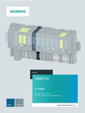
Siemens SIMATIC ET 200SP User Manual (74 pages)
Analog Input Module AI 4xTC HS
Brand: Siemens
|
Category: Control Unit
|
Size: 2.87 MB
Table of Contents
-
Preface
4
-
Table of Contents
6
-
1 Guide to Documentation
7
-
2 Product Overview
11
-
Properties
11
-
Spare Part Compatibility
13
-
-
3 Wiring
14
-
Wiring and Block Diagram
14
-
-
4 Parameters/Address Space
16
-
Measurement Types and Measuring Ranges
16
-
Parameters
16
-
Explanation of Parameters
20
-
Scalable Measuring Range
24
-
Configuration
26
-
Evaluate Status and Limits of Scalable Measuring Range
27
-
REAL Representation
29
-
Address Space
30
-
-
5 Interrupts/Diagnostics Alarms
38
-
Status and Error Display
38
-
Interrupts
40
-
Diagnostics Alarms
41
-
-
6 Technical Specifications
43
-
Parameter Data Records
50
-
Dependencies When Configuring with GSD File
50
-
Parameter Assignment and Structure of the Parameter Data Record (S7 Representation)
52
-
Parameter Assignment and Structure of Channel Parameter (REAL Representation)
60
-
-
Representation of Analog Values
68
-
Representation of Input Ranges
69
-
Representation of Analog Values in Voltage Measuring Ranges
69
-
Representation of Analog Values for Thermocouples
70
-
-
Siemens SIMATIC ET 200SP Workshop Manual (73 pages)
Analog input module AI 4xRTD/TC 2-/3-/4-wire HF (6ES7134-6JD00-0CA1)
Brand: Siemens
|
Category: Network Hardware
|
Size: 1.43 MB
Table of Contents
-
Preface
4
-
Table of Contents
5
-
1 Guide to Documentation
6
-
2 Product Overview
8
-
Properties
8
-
-
3 Wiring
11
-
Pin Assignment
11
-
Schematic Circuit Diagram
13
-
-
4 Parameters/Address Space
14
-
Measurement Types and Measuring Ranges
14
-
Parameters
19
-
Explanation of Parameters
24
-
Scalable Measuring Range
29
-
Configuration
31
-
Evaluating Data Record 235
32
-
Address Space
35
-
-
5 Interrupts/Diagnostics Alarms
36
-
Status and Error Display
36
-
Interrupts
38
-
Diagnostics Alarms
39
-
-
6 Technical Specifications
41
-
Parameter Data Record
48
-
Dependencies When Configuring with GSD File
48
-
Parameter Assignment and Structure of Parameter Data Record
53
-
Switchable Wire Break Check
62
-
-
Representation of Analog Values
63
-
Representation of Input Ranges
64
-
Representation of Analog Values in Voltage Measuring Ranges
65
-
Representation of Analog Values for Resistance-Type Sensors
66
-
Representation of Analog Values for Thermal Resistors
67
-
Representation of Analog Values for Thermocouples
70
-
-
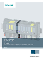
Siemens SIMATIC ET 200SP Manual (70 pages)
Analog input module AI 8xRTD/TC 2-wire HF
Brand: Siemens
|
Category: Industrial Equipment
|
Size: 1.47 MB
Table of Contents
-
Preface
4
-
Table of Contents
5
-
Guide to Documentation
6
-
Product Overview
8
-
Properties
8
-
Wiring
10
-
Pin Assignment
10
-
Block Diagram
11
-
Parameters/Address Space
12
-
Measurement Types and Measuring Ranges
12
-
Parameters
16
-
Explanation of Parameters
21
-
Scalable Measuring Range
26
-
Configuration
29
-
Evaluating Data Record 235
30
-
Address Space
33
-
Interrupts/Diagnostics Alarms
34
-
Status and Error Displays
34
-
Interrupts
36
-
Diagnostics Alarms
38
-
Technical Specifications
40
-
Parameter Data Record
46
-
Dependencies When Configuring with GSD File
46
-
Parameter Assignment and Structure of Parameter Data Record
51
-
Switchable Wire Break Check
60
-
Representation of Analog Values
61
-
Representation of Input Ranges
62
-
Representation of Analog Values in Voltage Measuring Ranges
63
-
Representation of Analog Values for Resistance-Type Sensors
64
-
Representation of Analog Values for Thermal Resistors
65
-
Representation of Analog Values for Thermocouples
67

Siemens SIMATIC ET 200SP Product Information (75 pages)
Brand: Siemens
|
Category: I/O Systems
|
Size: 1.66 MB
Table of Contents
-
Preface
3
-
Table of Contents
4
-
1 Module Overview of ET 200SP
5
-
Possible Combinations of Baseunits and I/O Modules
5
-
Cpus
15
-
Interface Modules
17
-
Baseunits
19
-
I/O Modules
21
-
Motor Starters
23
-
Accessories
24
-
-
2 Supplements to ET 200SP Documentation
31
-
System Manual
31
-
Baseunits Manual
36
-
Special Consideration for Baseunits with Functional Versions < 04
36
-
CPU Manuals
37
-
Interface Module Manuals
38
-
I/O Module Manuals
45
-
Digital Module Device Manuals
47
-
Analog Module Device Manuals
53
-
Communications Module Manuals
61
-
-
3 Using ET 200SP Higher than 2 000 M above Sea Level
63
-
Ambient Temperature and Installation Altitude
63
-
Listing of the Modules
64
-
Restrictions
75
-

Siemens SIMATIC ET 200SP Manual (52 pages)
System power supply
Brand: Siemens
|
Category: Power Supply
|
Size: 1.82 MB
Table of Contents
-
Overview
3
-
Table of Contents
5
-
1 Safety Instructions
7
-
General Safety Instructions
7
-
Safety Instructions for Hazardous Zones
7
-
-
2 Description, Device Design, Dimension Drawing
9
-
Device Description
9
-
Connections and Terminal Designation
10
-
Potentiometer
11
-
Status Displays and Signaling
12
-
Block Diagram
14
-
Dimensions and Weight
15
-
-
3 Mounting/Removal
17
-
4 Mounting Position, Mounting Clearances
19
-
Standard Mounting Position
19
-
Other Mounting Positions
20
-
6Ep7133-6Ab00-0Bn0
20
-
6Ep7133-6Ae00-0Bn0
21
-
-
5 Installation
23
-
Line-Side Connection
23
-
Output-Side Connection
25
-
-
6 Technical Data
27
-
Input
27
-
Output
29
-
Efficiency
32
-
Closed-Loop Control
33
-
Protection and Monitoring
33
-
Mtbf
33
-
Mechanical System
34
-
Dimension Drawing
34
-
-
7 Safety, Approvals, EMC
35
-
Safety
35
-
Test Voltage
36
-
Approvals
37
-
Emc
37
-
-
8 Environmental Conditions
39
-
9 Applications
41
-
Parallel Connection to Increase the Power Rating
41
-
Series Connection for Increased Voltage
43
-
Overload Protection in the 24 V Output Circuit
44
-
Protection against Short-Time Voltage Dips
45
-
Protecting against Longer Power Failures
46
-
-
10 Environment
49
-
11 Service & Support
51
Siemens SIMATIC ET 200SP Manual (63 pages)
Technology module TM Poslnput 1
Brand: Siemens
|
Category: Industrial Equipment
|
Size: 4.36 MB
Table of Contents
-
Preface
4
-
Table of Contents
6
-
Documentation Guide
7
-
Product Overview
9
-
Properties
9
-
Functions
11
-
Acquisition of Encoder Signals
11
-
Position Input with SSI Absolute Encoder
11
-
Counting with Incremental or Pulse Encoder
12
-
Measured Value Determination
14
-
Switching the Outputs at Comparison Values
15
-
Position Input for Motion Control
16
-
Additional Functions
16
-
Wiring
18
-
Pin Assignment
18
-
Configuring/Address Space
26
-
Configuring
26
-
Reaction to CPU STOP
28
-
Address Space
28
-
Parameters
29
-
Control and Feedback Interface
37
-
Assignment of the Control Interface
38
-
Assignment of the Feedback Interface
40
-
Interrupts/Diagnostic Messages
41
-
Status and Error Displays
41
-
Diagnostic Messages
43
-
Interrupts
45
-
Trigger a Diagnostic Interrupt
45
-
Cause of the Error Triggering a Diagnostic Interrupt
47
-
Triggering of a Hardware Interrupt
48
-
Events Which Can Trigger a Hardware Interrupt
49
-
Technical Specifications
50
-
Parameter Data Records
58

Siemens SIMATIC ET 200SP Manual (66 pages)
Analog input module AI 2xU/I 2-/4-wire HF
Brand: Siemens
|
Category: Industrial Electrical
|
Size: 3.14 MB
Table of Contents
-
Table of Contents
4
-
1 Preface
5
-
Open Source Software
5
-
Security Information
5
-
-
2 ET 200SP Documentation Guide
6
-
3 Product Overview
11
-
Properties
11
-
-
4 Wiring
13
-
Wiring and Block Diagram
13
-
-
5 Parameters/Address Space
18
-
Measurement Types and Measuring Ranges
18
-
Parameters
19
-
Explanation of Parameters
23
-
Measuring Range Adjustment
27
-
Scaling of Measured Values
31
-
Address Space
34
-
-
6 Interrupts/Diagnostics Alarms
38
-
Status and Error Displays
38
-
Interrupts
40
-
Diagnostics Alarms
42
-
-
7 Technical Specifications
43
-
Parameter Data Record
48
-
Dependencies When Configuring with GSD File
48
-
Parameter Assignment and Structure of Parameter Data Record
50
-
-
Representation of Analog Values
62
-
Representation of Input Ranges
63
-
Representation of Analog Values in Voltage Measuring Ranges
64
-
Representation of Analog Values in the Current Measuring Ranges
65
-
Measured Values for Wire Break
66
-

Siemens SIMATIC ET 200SP Manual (72 pages)
Brand: Siemens
|
Category: Industrial Equipment
|
Size: 1.65 MB
Table of Contents
-
Technische Daten
5
-
Product Information
14
-
Security Information
14
-
Product Overview
15
-
Technical Specifications
17
-
Dimension Drawing
22
-
Installation
23
-
Information Produit
26
-
Notes Relatives À la Sécurité
26
-
Caractéristiques Techniques
29
-
Présentation du Produit
30
-
Montage
35
-
Información del Producto
38
-
Información de Seguridad
38
-
Datos Técnicos
41
-
Descripción del Producto
42
-
Principios Básicos
47
-
Montaje
47
-
Informazioni Sul Prodotto
50
-
Indicazioni DI Sicurezza
50
-
Dati Tecnici
53
-
Disegno Quotato
58
Siemens SIMATIC ET 200SP Manual (53 pages)
Digital output module F-DQ 8x24VDC/0.5A PP HF (6ES7136-6DC00-0CA0)
Brand: Siemens
|
Category: Control Unit
|
Size: 1.91 MB
Table of Contents
-
Preface
3
-
Table of Contents
5
-
1 Documentation Guide
7
-
2 Product Overview
11
-
Properties
11
-
-
3 Connecting
14
-
Wiring and Block Diagram
14
-
-
4 Parameters/Address Space
16
-
Parameters
16
-
Explanation of Parameters
18
-
F-Parameters
18
-
Behavior after Channel Fault
18
-
Reintegration after Channel Fault
18
-
Parameters of the Channels
19
-
Maximum Test Period
19
-
Disable Dark Test for 48 Hours
19
-
Activated
20
-
Max. Readback Time Dark Test
20
-
Max. Readback Time Light Test
22
-
Activated Light Test
23
-
Channel Failure Acknowledge
24
-
Address Space
24
-
-
5 Applications of the F-I/O Module
26
-
Installation of the Ground Line between the Power Supply and the Baseunit
26
-
Application: Wiring a Load to each Digital Output
27
-
Application: Wiring Two Loads in Parallel to each Digital Output
29
-
Application: Connection of a Fail-Safe Digital Input to each Digital Output
31
-
Application: Connection of the ET 200SP Digital Output Module F-RQ 1X24Vdc/24
35
-
-
6 Interrupts/Diagnostic Messages
37
-
Status and Error Display
37
-
Interrupts
40
-
Diagnostics Alarms
42
-
Value Status
46
-
-
7 Technical Specifications
47
-
Response Times
50
-
Switching of Loads
51
-
Connecting Capacitive Loads
51
-
Switching of Inductive Loads
53
-
-

Siemens SIMATIC ET 200SP Manual (57 pages)
Interface, IM 155-6 PN HS
Brand: Siemens
|
Category: Control Unit
|
Size: 1.22 MB
Table of Contents
-
Preface
4
-
Table of Contents
6
-
1 Documentation Guide
7
-
2 Product Overview
11
-
Properties
11
-
Functions
15
-
Profienergy
23
-
Configuration Control (Option Handling)
23
-
Use of Fail-Safe Modules
24
-
Multi Hot Swap
24
-
-
3 Connecting
25
-
Terminal Assignment
25
-
Schematic Circuit Diagram
31
-
-
4 Parameters/Address Space
32
-
Parameters
32
-
Explanation of Parameters
32
-
Configuration Control
32
-
Substitute Value Behavior
33
-
Status of the Supply Voltage L+ of the I/O Modules
33
-
-
5 Interrupts, Diagnostics, Error, and System Messages
34
-
Status and Error Displays
34
-
Interrupts
38
-
Triggering of a Diagnostics Interrupt
39
-
Triggering a Hardware Interrupt
39
-
Triggering a Swapping Interrupt
40
-
Alarms
40
-
Maintenance Events
42
-
Channel Diagnostics
43
-
Invalid Configuration States of the ET 200SP on PROFINET IO
44
-
Failure of Supply Voltage L+ at Baseunit BU
44
-
STOP of the IO Controller and Recovery of the IO Device
45
-
-
6 Compatibility
46
-
7 Technical Specifications
47
-
Dimensional Drawing
57
-
Siemens SIMATIC ET 200SP Manual (56 pages)
Digital Output Module DQ 4×24..230VAC/2A HF 6ES7132-6FD00-0CU0
Brand: Siemens
|
Category: Control Unit
|
Size: 1.67 MB
Table of Contents
-
Preface
4
-
Table of Contents
6
-
1 Guide to Documentation
7
-
2 Product Overview
11
-
Properties
11
-
Functions
14
-
-
3 DQ Mode
17
-
Wiring
17
-
Wiring and Block Diagram
17
-
Parameters/Address Space
19
-
Parameters
19
-
Explanation of Parameters
22
-
Address Space
25
-
Interrupts/Diagnostics Alarms
27
-
Status and Fault Displays
27
-
Interrupts
28
-
Diagnostics Alarms
29
-
-
4 PC Mode
30
-
Wiring
30
-
Wiring and Block Diagram
30
-
Parameters/Address Space
32
-
Parameters
32
-
Explanation of Parameters
35
-
Address Space
39
-
Interrupts/Diagnostics Alarms
42
-
Status and Fault Displays
42
-
Interrupts
43
-
Diagnostics Alarms
44
-
-
5 Technical Specifications
45
-
Parameter Data Record
52
-
Parameter Assignment and Structure of Parameter Data Record
52
-
Error Transferring the Data Record DQ
56
-
-

Siemens SIMATIC ET 200SP Manual (54 pages)
Technology Module TM Count 1x24V
Brand: Siemens
|
Category: Power distribution unit
|
Size: 0.65 MB
Table of Contents
-
Preface
3
-
Table of Contents
5
-
Documentation Guide
7
-
Product Overview
9
-
Properties
9
-
Functions
12
-
Detection of Counting Signals
12
-
Measured Value Determination
14
-
Switching the Outputs at Comparison Values
15
-
Position Input for Motion Control
15
-
Additional Functions
16
-
Wiring
17
-
Pin Assignment
17
-
Configuring/Address Space
23
-
Configuring
23
-
Reaction to CPU STOP
25
-
Address Space
26
-
Control and Feedback Interface
27
-
Assignment of the Control Interface
27
-
Assignment of the Feedback Interface
29
-
Interrupts/Diagnostic Messages
31
-
Status and Error Displays
31
-
Diagnostic Messages
34
-
Interrupts
36
-
Trigger a Diagnostic Interrupt
36
-
Cause of the Error Triggering a Diagnostic Interrupt
37
-
Triggering of a Hardware Interrupt
38
-
Events Which Can Trigger a Hardware Interrupt
39
-
Technical Specifications
41
-
Parameter Data Records
49
Siemens SIMATIC ET 200SP Manual (57 pages)
Technology module TM PTO 2x24V
Brand: Siemens
|
Category: Control Unit
|
Size: 2.62 MB
Table of Contents
-
Preface
4
-
Table of Contents
6
-
Documentation Guide
7
-
ET 200SP Documentation Guide
7
-
Product Overview
12
-
Properties
12
-
Functions
15
-
Pulse Train Output (PTO)
15
-
Connecting
18
-
Pin Assignment
18
-
Configuring/Address Space
23
-
Configuring
23
-
Parameter Setting
26
-
Address Space
30
-
4.4 Control and Feedback Interface
31
-
Assignment of the Control Interface
31
-
Assignment of the Feedback Interface
35
-
Enabling the Pulse Output
40
-
Reaction to CPU STOP
41
-
Isochronous Mode
42
-
Interrupts/Diagnostic Alarms
43
-
Status and Error Displays
43
-
Diagnostic Alarms
45
-
Technical Specifications
48
-
Parameter Data Record
53
-
Parameter Assignment and Structure of the Parameter Data Record
53
-
Parameter Validation Error
56
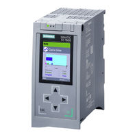
Siemens SIMATIC ET 200SP Function Manual (55 pages)
Isochronous mode
Brand: Siemens
|
Category: I/O Systems
|
Size: 1.99 MB
Table of Contents
-
Preface
4
-
Table of Contents
7
-
1 Documentation Guide
8
-
2 What Is Isochronous Mode
13
-
3 Use of Isochronous Mode
16
-
4 Time Sequence of Synchronization
18
-
Time Sequence of Synchronization on PROFINET IO and PROFIBUS DP
18
-
Time Sequence of Synchronization in the Central Configuration
20
-
-
5 Configuring Isochronous Mode
23
-
Configuring Isochronous Mode for Distributed I/O on PROFINET IO
25
-
Configuring Isochronous Mode for Central I/O in S7-1500
27
-
Configuring Joint Isochronous Operation of Central and Distributed I/O
31
-
Configuring Isochronous Mode for Distributed I/O on PROFIBUS DP
33
-
Configuring Isochronous Mode for a Motion Control Application
35
-
Setting the Application Cycle and Delay Time
42
-
-
6 Programming Isochronous Mode
44
-
Program Execution According to the IPO Model
45
-
Program Execution According to the OIP Model
47
-
Programming of Isochronous Mode for Motion Control Applications
49
-
Glossary
50
-
Index
55
-

Siemens SIMATIC ET 200SP Manual (49 pages)
Analog input module, AI 2xU/I 2-/4-wire HS 6ES7134-6HB00-0DA1
Brand: Siemens
|
Category: I/O Systems
|
Size: 1.72 MB
Table of Contents
-
Preface
4
-
Table of Contents
6
-
1 Documentation Guide
7
-
2 Product Overview
11
-
Properties
11
-
-
3 Connecting
14
-
Wiring and Block Diagram
14
-
-
4 Parameters/Address Space
17
-
Measurement Types and Measuring Ranges
17
-
Parameters
17
-
Description of Parameters
20
-
Oversampling
22
-
Address Space
25
-
-
5 Interrupts/Diagnostics Interrupts
27
-
Status and Error Displays
27
-
Interrupts
29
-
Diagnostics Alarms
31
-
-
6 Technical Specifications
33
-
Parameter Data Record
38
-
Dependencies When Configuring with GSD File
38
-
Parameter Assignment and Structure of the Parameter Data Record
40
-
-
Representation of Analog Values
46
-
Representation of Input Ranges
47
-
Representation of Analog Values in Voltage Measuring Ranges
48
-
Representation of Analog Values in the Current Measuring Ranges
49
-
-
Siemens SIMATIC ET 200SP Manual (48 pages)
Analog output module AQ 2xU/I HS
Brand: Siemens
|
Category: I/O Systems
|
Size: 1.81 MB
Table of Contents
-
Preface
4
-
Table of Contents
6
-
1 Documentation Guide
7
-
2 Product Overview
11
-
Properties
11
-
-
3 Connecting
14
-
Wiring and Block Diagram
14
-
-
4 Parameters/Address Space
18
-
Output Types and Output Ranges
18
-
Parameters
19
-
Description of Parameters
21
-
Oversampling
22
-
Address Space
24
-
-
5 Interrupts/Diagnostics Alarms
27
-
Status and Error Displays
27
-
Interrupts
29
-
Diagnostics Alarms
30
-
-
6 Technical Specifications
31
-
Parameter Data Record
37
-
Dependencies When Configuring with GSD File
37
-
Parameter Assignment and Structure of the Parameter Data Record
38
-
-
Representation of Analog Values
43
-
Representation of Output Ranges
44
-
Representation of Analog Values in the Voltage Output Ranges
45
-
Representation of Analog Values in the Current Output Ranges
47
-
-

Siemens SIMATIC ET 200SP Manual (35 pages)
Reading and Writing RFID Data via IO-Link
Brand: Siemens
|
Category: Controller
|
Size: 1.88 MB
Table of Contents
-
Legal Information
2
-
Table of Contents
3
-
Task
4
-
Solution
6
-
Overview
6
-
Description of the Core Functionality
8
-
Reading / Writing of RFID Data from / to a Transponder
9
-
Hardware and Software Components
12
-
Validity
12
-
Components Used
12
-
Mode of Operation
14
-
General Overview
14
-
Functionality
17
-
Program Details on FB «Iolreadant» (FB3)
17
-
Program Details on FB «Iolwriteant» (FB5)
18
-
Error and Status Display
20
-
Installation and Commissioning
21
-
Hardware Installation
21
-
Installing the Software
22
-
Commissioning
22
-
Restore S7-1500 CPU Factory Setting
22
-
Setting the IP Addresses
23
-
Changing the IP Addresses of the PC/PG
23
-
Configuration of the IO-Link Master
24
-
Change the IP Address of the CPU
26
-
Changing IP Address of the ET 200SP
26
-
Loading the STEP 7 Project into the S7 CPU
27
-
Operating the Application
28
-
Menu Navigation of the HMI
28
-
Reading RFID Data from the Transponder
29
-
Writing RFID Data to the Transponder
30
-
Error States
31
-
Appendix
33
-
Service and Support
33
-
Industry Mall
34
-
Links and Literature
34
-
Change Documentation
35
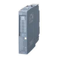
Siemens SIMATIC ET 200SP Manual (44 pages)
HA Digital Input Module DI 16x24VDC
Brand: Siemens
|
Category: I/O Systems
|
Size: 0.33 MB
Table of Contents
-
Table of Contents
3
-
1 Security Information
5
-
2 Product Overview
7
-
Properties of the I/O Module DI 16X24Vdc HA
7
-
-
3 Wiring
11
-
Terminal Assignment of the I/O Module DI 16X24Vdc HA
11
-
Schematic Circuit Diagram
13
-
-
4 Parameters
15
-
Parameters of the I/O Module DI 16X24Vdc HA
15
-
Module/Channel Parameters
16
-
Explanation of the Module/Channel Parameters
18
-
-
5 Displays and Interrupts
21
-
Status and Error Displays of the I/O Module DI 16X24Vdc HA
21
-
Interrupts
24
-
-
6 Technical Specifications
25
-
Drivers, Parameters, Diagnostics Messages and Address Space
31
-
Concept of the Driver and Diagnostics Blocks
31
-
Parameter Assignment
33
-
A.2 Parameter Assignment
33
-
Parameter Assignment and Structure of the Module/Channel Parameters
35
-
Diagnostics Messages and Maintenance Events
38
-
Hardware Interrupts
40
-
A.5 Hardware Interrupts
40
-
Address Space
41
-
A.6 Address Space
41
-
Address Space of the Time Stamping (Accuracy 1 Ms)
42
-
Index
43
-
-

Siemens SIMATIC ET 200SP Equipment Manual (44 pages)
CM PtP communications module
Brand: Siemens
|
Category: Control Unit
|
Size: 1.96 MB
Table of Contents
-
Preface
3
-
Table of Contents
6
-
Documentation Guide
7
-
Product Overview
11
-
Properties
11
-
Functions
15
-
Properties of the Interfaces
16
-
Properties of the RS232 Interface
16
-
Properties of the RS422/485 Interface
18
-
Connecting
19
-
Introduction
19
-
RS232 Interface of the Communications Module
20
-
RS422/485 Interface of the Communications Module
23
-
Installation Guidelines
25
-
Parameters/Address Space
26
-
Configuring
26
-
Reaction to CPU STOP
27
-
Parameter Setting
28
-
Address Space
34
-
Programming
35
-
Interrupts/Diagnostics Alarms
37
-
Status and Error Displays
37
-
Diagnostic Alarms
39
-
Technical Specifications
41
Siemens SIMATIC ET 200SP Manual (41 pages)
Analog input module, AI 4xU/I 2-wire ST 6ES7134-6HD01-0BA1
Brand: Siemens
|
Category: I/O Systems
|
Size: 1.22 MB
Table of Contents
-
Preface
4
-
Table of Contents
6
-
1 Documentation Guide
7
-
2 Product Overview
12
-
Properties
12
-
-
3 Wiring up
15
-
Wiring and Block Diagram
15
-
-
4 Parameters/Address Space
17
-
Measuring Types and Ranges
17
-
Parameters
18
-
Explanation of the Parameters
20
-
Address Space
22
-
-
5 Interrupts/Diagnostics Alarms
23
-
Status and Error Display
23
-
Interrupts
25
-
Diagnostics Alarms
26
-
-
6 Technical Specifications
27
-
Parameter Data Record
32
-
Dependencies When Configuring with GSD File
32
-
Parameter Assignment and Structure of the Parameter Data Record
33
-
Error in Transferring the Data Record Analog Input
37
-
-
Representation of Analog Values
38
-
Representation of Input Ranges
39
-
Representation of Analog Values in Voltage Measuring Ranges
40
-
Representation of Analog Values in the Current Measuring Ranges
41
-
-

Siemens SIMATIC ET 200SP Product Information (38 pages)
Brand: Siemens
|
Category: I/O Systems
|
Size: 0.92 MB
Table of Contents
-
Preface
3
-
Table of Contents
5
-
1 Product Overview
7
-
What Are Fail-Safe Automation Systems and Fail-Safe Modules
7
-
Fault Reactions with Fail-Safe Modules
10
-
-
2 Application Planning
13
-
Forming Potential Groups with Fail-Safe Modules
13
-
-
3 Installation
15
-
Basics
15
-
-
4 Connecting
17
-
Additional Rules and Provisions for Operation of the ET 200SP with Fail-Safe Modules
17
-
Safe Functional Extra-Low Voltage (SELV) for Fail-Safe Modules
17
-
Requirements of Sensors and Actuators for Fail-Safe Modules
18
-
Capacitive Crosstalk of Digital Input/Output Signals
20
-
-
5 Configuring
21
-
Assigning the F-Destination Address for Fail-Safe Modules
21
-
Assigning the F-Destination Address
21
-
-
6 Maintenance
23
-
Firmware Update
23
-
-
7 Technical Specifications
25
-
Electromagnetic Compatibility of Fail-Safe Modules
25
-
Standards and Approvals
27
-
-
8 Accessories/Spare Parts
29
-
Lightning Protection and Overvoltage Protection for Fail-Safe Modules
29
-
Glossary
31
-

Siemens SIMATIC ET 200SP Manual (38 pages)
Analog output module AQ 4xU/I ST 6ES7135-6HD00-0BA1
Brand: Siemens
|
Category: Control Unit
|
Size: 1.17 MB
Table of Contents
-
Preface
4
-
Table of Contents
6
-
1 Documentation Guide
7
-
2 Product Overview
11
-
Properties
11
-
-
3 Wiring up
14
-
Terminal Assignment
14
-
Schematic Circuit Diagram
15
-
-
4 Parameters/Address Space
16
-
Output Ranges
16
-
Parameters
17
-
Explanation of the Parameters
19
-
Address Space
20
-
-
5 Interrupts/Diagnostics Alarms
21
-
Status and Error Display
21
-
Interrupts
23
-
Diagnostics Alarms
24
-
-
6 Technical Specifications
25
-
Parameter Data Record
30
-
Dependencies When Configuring with GSD File
30
-
Parameter Assignment and Structure of the Parameter Data Record
31
-
-
Representation of Analog Values
34
-
Representation of Output Ranges
35
-
Representation of Analog Values in the Voltage Output Ranges
36
-
Representation of Analog Values in the Current Output Ranges
37
-
-

Siemens SIMATIC ET 200SP Manual (40 pages)
Brand: Siemens
|
Category: I/O Systems
|
Size: 0.89 MB
Table of Contents
-
Preface
4
-
Table of Contents
5
-
1 Documentation Guide
6
-
2 Product Overview
8
-
Operating Principle
8
-
Properties
9
-
Differences between F-CPU 1510SP F-1 PN and Standard CPU 1510SP-1 PN
12
-
Operating and Display Elements
14
-
Front View of the Module with Busadapter
14
-
Mode Switch
15
-
Functions
15
-
Profinet Io
15
-
Profienergy
16
-
Profibus Dp
17
-
Memory Reset
18
-
Restoring the Factory Settings of the CPU
19
-
-
3 Wiring
22
-
4 Interrupts, Error Messages, Diagnostics and System Alarms
27
-
Status and Error Display of the CPU
27
-
-
5 Technical Specifications
30
-
Dimension Drawing
40
-

Siemens SIMATIC ET 200SP Manual (40 pages)
Communication module IO-Link Master CM 4xIO-Link (6ES7137-6BD00-0BA0)
Brand: Siemens
|
Category: Control Unit
|
Size: 1.46 MB
Table of Contents
-
Preface
4
-
Table of Contents
5
-
1 Documentation Guide
6
-
2 Product Overview
10
-
Properties
10
-
Functions
13
-
Replacement of the IO-Link Master CM 4Xio-Link Communication Module with an Electronic Coding Element Type H
13
-
Time-Based IO
15
-
Reset Communication Module to Factory Settings
16
-
-
3 Connecting
17
-
Wiring and Block Diagram
17
-
-
4 Parameters/Address Space
21
-
Parameters
21
-
Declaration of Parameters
23
-
Address Space
25
-
-
5 Diagnostic Alarms
28
-
Status and Error Displays
28
-
Diagnostic Alarms
31
-
-
6 Technical Specifications
32
-
Parameter Data Record
36
-
Parameter Assignment and Structure of Parameter Data Set
36
-
-
Siemens SIMATIC ET 200SP Manual (37 pages)
Digital input module DI 8xNAMUR
Brand: Siemens
|
Category: Control Unit
|
Size: 1.17 MB
Table of Contents
-
Manual, 02/2014, A5E03894478
2
-
Preface
4
-
Table of Contents
5
-
-
1 Guide to Documentation
6
-
2 Product Overview
8
-
Properties
8
-
-
3 Wiring
10
-
Pin Assignment
10
-
Block Diagram
11
-
-
4 Parameters/Address Space
12
-
Parameters
12
-
Explanation of Parameters
14
-
Pulse Stretching
17
-
Address Space
19
-
-
5 Interrupts/Diagnostics Alarms
20
-
Status and Fault Displays
20
-
Interrupts
23
-
Diagnostics Alarms
25
-
Diagnostics for Changeover Contact Sensor Type
26
-
Chatter Monitoring
27
-
-
6 Technical Specifications
30
-
Parameter Data Record
33
-
Dependencies When Configuring with GSD Files
33
-
Parameter Assignment and Structure of Parameter Data Record
34
-
-
Siemens SIMATIC ET 200SP Manual (36 pages)
HA Digital Output Module DQ 16x24VDC/0.5A
Brand: Siemens
|
Category: I/O Systems
|
Size: 0.3 MB
Table of Contents
-
Table of Contents
3
-
1 Security Information
5
-
2 Product Overview
7
-
Properties of the I/O Module DQ 16X24Vdc/0.5A HA
7
-
-
3 Wiring
9
-
Terminal Assignment of the I/O Module DQ 16X24Vdc/0.5A HA
9
-
Schematic Circuit Diagram
11
-
-
4 Parameters
13
-
Parameters of the I/O Module DQ 16X24Vdc/0.5A HA
13
-
Module/Channel Parameters
14
-
Explanation of the Module/Channel Parameters
15
-
-
5 Displays and Interrupts
17
-
Status and Error Displays of the I/O Module DQ 16X24Vdc/0.5A HA
17
-
Interrupts
20
-
-
6 Technical Specifications
21
-
Drivers, Parameters, Diagnostics Messages and Address Space
25
-
Concept of the Driver and Diagnostics Blocks
25
-
Parameter Assignment
27
-
A.2 Parameter Assignment
27
-
Parameter Assignment and Structure of the Module/Channel Parameters
28
-
Diagnostics Messages and Maintenance Events
31
-
Address Space
33
-
A.5 Address Space
33
-
Index
35
-
-
Siemens SIMATIC ET 200SP Manual (34 pages)
Analog output module AQ 2xU/I HF (6ES7135-6HB00-0CA1)
Brand: Siemens
|
Category: Control Unit
|
Size: 0.86 MB
Table of Contents
-
Preface
4
-
Table of Contents
5
-
1 Guide to Documentation
6
-
2 Product Overview
8
-
Properties
8
-
-
3 Wiring
10
-
Pin Assignment
10
-
Block Diagram
11
-
-
4 Parameters/Address Space
12
-
Output Type and Output Ranges
12
-
Parameters
13
-
Explanation of Parameters
15
-
Address Space
16
-
-
5 Interrupts/Diagnostics Alarms
17
-
Status and Error Displays
17
-
Interrupts
19
-
Diagnostics Alarms
20
-
-
6 Technical Specifications
21
-
Parameter Data Record
25
-
Dependencies When Configuring with GSD File
25
-
Parameter Assignment and Structure of Parameter Data Record
26
-
-
Representation of Analog Values
30
-
Representation of Output Ranges
31
-
Representation of Analog Values in the Voltage Output Ranges
32
-
Representation of Analog Values in the Current Output Ranges
33
-
-
Siemens SIMATIC ET 200SP Manual (41 pages)
Digital Input Module, DI 8x24VDC HF 6ES713106BF00-0CA0
Brand: Siemens
|
Category: I/O Systems
|
Size: 1.96 MB
Table of Contents
-
Preface
4
-
Table of Contents
6
-
1 Documentation Guide
7
-
2 Product Overview
12
-
Properties
12
-
-
3 Wiring
15
-
Wiring and Block Diagrams
15
-
-
4 Parameters/Address Space
18
-
Parameters
18
-
Explanation of Parameters
20
-
Address Space
23
-
-
5 Interrupts/Diagnostics Alarms
29
-
Status and Error Displays
29
-
Interrupts
31
-
Diagnostics Alarms
33
-
-
6 Technical Specifications
34
-
Parameter Data Record
38
-
Parameter Assignment and Structure of Parameter Data Record
38
-
-

Siemens SIMATIC ET 200SP Manual (35 pages)
Analog, AI 2xI 2/4-wire ST
Brand: Siemens
|
Category: I/O Systems
|
Size: 1.08 MB
Table of Contents
-
Preface
4
-
Table of Contents
5
-
1 Documentation Guide
6
-
2 Product Overview
9
-
Properties
9
-
-
3 Wiring
11
-
Wiring and Block Diagram
11
-
-
4 Parameters/Address Space
13
-
Measurement Types and Measuring Ranges
13
-
Parameters
14
-
Description of Parameters
16
-
Address Space
18
-
-
5 Interrupts/Diagnostics Alarms
20
-
Status and Error Displays
20
-
Interrupts
22
-
Diagnostics Alarms
23
-
-
6 Technical Specifications
24
-
Parameter Data Record
28
-
Dependencies When Configuring with GSD File
28
-
Parameter Assignment and Structure of the Parameter Data Record
29
-
-
Representation of Analog Values
33
-
Representation of Analog Values for Analog Inputs
33
-
Representation of Input Ranges
34
-
Representation of Analog Values in the Current Measuring Ranges
35
-
-
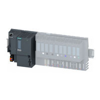
Siemens SIMATIC ET 200SP Equipment Manual (43 pages)
Brand: Siemens
|
Category: I/O Systems
|
Size: 1.21 MB
Table of Contents
-
Preface
4
-
Table of Contents
6
-
1 ET 200SP Documentation Guide
7
-
2 Product Overview
12
-
New Functions
12
-
Operating Principle
14
-
Properties
15
-
Operating and Display Elements
20
-
Front View of the Module with Busadapter
20
-
Mode Switch
21
-
-
3 Wiring
22
-
4 Interrupts, Error Messages, Diagnostics and System Alarms
26
-
Status and Error Display of the CPU
26
-
-
5 Technical Specifications
29
-
Dimension Drawing
43

Siemens SIMATIC ET 200SP Manual (39 pages)
Digital module DQ 8x24VDC/0.5A HF
Brand: Siemens
|
Category: Industrial Electrical
|
Size: 1.8 MB
Table of Contents
-
Preface
4
-
Table of Contents
6
-
1 Documentation Guide
7
-
2 Product Overview
12
-
Properties
12
-
-
3 Wiring
15
-
Wiring and Block Diagram
15
-
-
4 Parameters/Address Space
18
-
Parameters
18
-
Explanation of Parameters
20
-
Address Space
21
-
-
5 Interrupts/Diagnostics Alarms
28
-
Status and Error Displays
28
-
Interrupts
30
-
Diagnostics Alarms
31
-
-
6 Technical Specifications
32
-
Parameter Data Record
36
-
Parameter Assignment and Structure of Parameter Data Record
36
-
-

Siemens SIMATIC ET 200SP Manual (34 pages)
analog input module AI 2xU st
Brand: Siemens
|
Category: I/O Systems
|
Size: 1.27 MB
Table of Contents
-
Preface
4
-
Table of Contents
5
-
1 Documentation Guide
6
-
2 Product Overview
9
-
Properties
9
-
-
3 Wiring
11
-
Wiring and Block Diagram
11
-
-
4 Parameters/Address Space
13
-
Measuring Types and Ranges
13
-
Parameters
14
-
Explanation of the Parameters
16
-
Address Space
19
-
-
5 Interrupts/Diagnostics Alarms
20
-
Status and Error Display
20
-
Interrupts
22
-
Diagnostics Alarms
22
-
-
6 Technical Specifications
23
-
Parameter Data Record
27
-
Dependencies When Configuring with GSD File
27
-
Parameter Assignment and Structure of the Parameter Data Record
28
-
-
Representation of Analog Values
32
-
Representation of Input Ranges
33
-
Representation of Analog Values in Voltage Measuring Ranges
34
-
-
Siemens SIMATIC ET 200SP Manual (34 pages)
Analog input module AI 8xI 2-/4-wire BA
Brand: Siemens
|
Category: Control Unit
|
Size: 0.95 MB
Table of Contents
-
Preface
4
-
Table of Contents
5
-
Documentation Guide
6
-
Product Overview
8
-
Properties
8
-
Wiring up
10
-
Wiring and Block Diagram
10
-
Parameters/Address Space
13
-
Measuring Types and Ranges
13
-
Parameters
13
-
Explanation of the Parameters
16
-
Address Space
18
-
Interrupts/Diagnostics Alarms
19
-
Status and Error Displays
19
-
Interrupts
21
-
Diagnostics Alarms
22
-
Technical Specifications
23
-
Parameter Data Record
27
-
Dependencies When Configuring with GSD File
27
-
Parameter Assignment and Structure of the Parameter Data Record
28
-
Representation of Analog Values
32
-
Representation of Input Ranges
33
-
Representation of Analog Values in the Current Measuring Ranges
34

Siemens SIMATIC ET 200SP Manual (33 pages)
Analog output module AQ 2xl ST
Brand: Siemens
|
Category: I/O Systems
|
Size: 0.99 MB
Table of Contents
-
Preface
4
-
Table of Contents
5
-
1 Documentation Guide
6
-
2 Product Overview
9
-
Properties
9
-
-
3 Wiring
11
-
Wiring and Block Diagram
11
-
-
4 Parameters/Address Space
13
-
Output Ranges
13
-
Parameters
14
-
Explanation of the Parameters
16
-
Address Space
17
-
-
5 Interrupts/Diagnostics Alarms
18
-
Status and Error Display
18
-
Interrupts
20
-
Diagnostics Alarms
21
-
-
6 Technical Specifications
22
-
Parameter Data Record
25
-
Dependencies When Configuring with GSD File
25
-
Parameter Assignment and Structure of the Parameter Data Record
26
-
-
Representation of Analog Values
30
-
Representation of Output Ranges
31
-
Representation of Analog Values in the Current Output Ranges
32
-
-
Siemens SIMATIC ET 200SP Manual (57 pages)
Brand: Siemens
|
Category: Industrial Equipment
|
Size: 0.92 MB
Siemens SIMATIC ET 200SP Manual (31 pages)
Analog input module AI 8xU BA
6ES7134-6FF00-0AA1
Brand: Siemens
|
Category: I/O Systems
|
Size: 0.84 MB
Table of Contents
-
Preface
4
-
Table of Contents
5
-
1 Documentation Guide
6
-
2 Product Overview
8
-
Properties
8
-
-
3 Wiring up
10
-
Wiring and Block Diagram
10
-
-
4 Parameters/Address Space
12
-
Measuring Types and Ranges
12
-
Parameters
13
-
Explanation of the Parameters
15
-
Address Space
17
-
-
5 Interrupts/Diagnostics Alarms
18
-
Status and Error Displays
18
-
Interrupts
20
-
Diagnostics Alarms
20
-
-
6 Technical Specifications
21
-
Parameter Data Record
24
-
Dependencies When Configuring with GSD File
24
-
Parameter Assignment and Structure of the Parameter Data Record
25
-
-
Representation of Analog Values
29
-
Representation of Input Ranges
30
-
Representation of Analog Values in Voltage Measuring Ranges
31
-
-
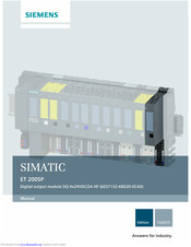
Siemens SIMATIC ET 200SP Manual (34 pages)
Digital output module DQ 4x24VDC/2A HF
Brand: Siemens
|
Category: I/O Systems
|
Size: 1.97 MB
Table of Contents
-
Preface
4
-
Table of Contents
5
-
1 Documentation Guide
6
-
2 Product Overview
9
-
Properties
9
-
-
3 Wiring
11
-
Wiring and Block Diagram
11
-
-
4 Parameters/Address Space
14
-
Parameters
14
-
Explanation of Parameters
16
-
Address Space
17
-
-
5 Interrupts/Diagnostics Alarms
22
-
Status and Error Displays
22
-
Interrupts
24
-
Diagnostics Alarms
24
-
-
6 Technical Specifications
26
-
Parameter Data Record
31
-
Parameter Assignment and Structure of Parameter Data Record
31
-
-

Siemens SIMATIC ET 200SP Manual (34 pages)
Digital output module, DQ 16x24VDC/0.5A ST, 6ES7132-6BH01-0BAQ
Brand: Siemens
|
Category: Control Unit
|
Size: 1.16 MB
Table of Contents
-
Preface
4
-
Table of Contents
6
-
1 Documentation Guide
7
-
2 Product Overview
12
-
Properties
12
-
-
3 Connecting
14
-
Wiring and Block Diagram
14
-
-
4 Parameters/Address Space
16
-
Parameters
16
-
Declaration of Parameters
18
-
Address Space
19
-
-
5 Interrupts/Diagnostic Alarms
21
-
Status and Error Display
21
-
Interrupts
23
-
Diagnostic Messages
24
-
-
6 Technical Specifications
25
-
Parameter Data Record
31
-
Parameter Assignment and Structure of Parameter Data Record
31
-
-

Siemens SIMATIC ET 200SP Manual (30 pages)
CM PtP communication module
Brand: Siemens
|
Category: Control Unit
|
Size: 0.69 MB
Table of Contents
-
Preface
3
-
Table of Contents
5
-
1 Documentation Guide
7
-
2 Product Overview
9
-
Properties
9
-
Accessories
10
-
Functions
11
-
Properties of the Interfaces
13
-
Properties of the RS232 Interface
13
-
Properties of the RS422/485 Interface
15
-
-
3 Connecting
17
-
RS232 and RS422/485 Interface of the Communication Module
17
-
Installation Guidelines
18
-
-
4 Parameters/Address Space
19
-
Parameter Assignment
19
-
Reaction to CPU STOP
19
-
Address Space
20
-
-
5 Programming
21
-
6 Error and System Messages
23
-
7 Technical Specifications
25
-
Dimensional Drawing
29
-

Siemens SIMATIC ET 200SP Manual (32 pages)
Digital output module RQ 4x120VDC-230VAC/5A NO ST (6ES7132-6HD01-0BB1)
Brand: Siemens
|
Category: Control Unit
|
Size: 1.19 MB
Table of Contents
-
Preface
4
-
Table of Contents
6
-
1 Documentation Guide
7
-
2 Product Overview
12
-
Properties
12
-
-
3 Wiring up
14
-
Wiring and Block Diagram
14
-
-
4 Parameters/Address Space
17
-
Parameters
17
-
Explanation of the Parameters
18
-
Address Space
19
-
-
5 Interrupts/Diagnostics Alarms
20
-
Status and Error Display
20
-
Interrupts
22
-
Diagnostics Alarms
22
-
-
6 Technical Specifications
23
-
Switching Cycles
28
-
Parameter Data Record
29
-
Parameter Assignment and Structure of the Parameter Data Record
29
-
-
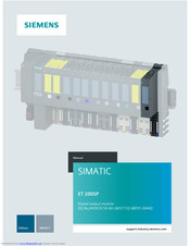
Siemens SIMATIC ET 200SP User Manual (32 pages)
Digital output module DQ 8x24VDC/0.5A BA (6ES7132-6BF01-0AA0)
Brand: Siemens
|
Category: Control Unit
|
Size: 1.11 MB
Table of Contents
-
Preface
4
-
Table of Contents
6
-
1 Documentation Guide
7
-
2 Product Overview
12
-
Properties
12
-
-
3 Wiring
14
-
Wiring and Block Diagram
14
-
-
4 Parameters/Address Space
17
-
Parameters
17
-
Explanation of the Parameters
19
-
Address Space
20
-
-
5 Interrupts/Diagnostics Alarms
21
-
Status and Error Display
21
-
Interrupts
23
-
Diagnostics Alarms
23
-
-
6 Technical Specifications
24
-
Parameter Data Record
29
-
Parameter Assignment and Structure of the Parameter Data Record
29
-
-
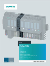
Siemens SIMATIC ET 200SP Equipment Manual (32 pages)
Digital output module RQ 4x120VDC-230VAC/5A NO MA ST
Brand: Siemens
|
Category: I/O Systems
|
Size: 1.98 MB
Table of Contents
-
Preface
4
-
Table of Contents
6
-
ET 200SP Documentation Guide
7
-
Product Overview
9
-
Properties
9
-
Wiring
11
-
Wiring and Block Diagram
11
-
Parameters/Address Space
15
-
Parameters
15
-
Explanation of the Parameters
17
-
Address Space
18
-
Interrupts/Diagnostics Alarms
20
-
Status and Error Display
20
-
Interrupts
22
-
Diagnostics Alarms
22
-
Technical Specifications
23
-
Switching Cycles
28
-
Parameter Data Record
30
-
Parameter Assignment and Structure of the Parameter Data Record
30
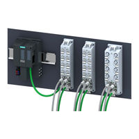
Siemens SIMATIC ET 200SP Manual (32 pages)
Mixed configuration
Brand: Siemens
|
Category: I/O Systems
|
Size: 0.96 MB
Table of Contents
-
Table of Contents
4
-
1 Preface
5
-
2 Documentation Guide
7
-
3 Product Overview
12
-
Baseunit BU-Send
12
-
Busadapter BA-Send 1Xfc
14
-
Properties
14
-
Wiring and Schematic Circuit Diagram
16
-
Diagnostics by Means of LED Display
17
-
-
4 Application Planning
18
-
5 Mounting
22
-
6 Connecting
23
-
Connecting Baseunit BU-Send
23
-
-
7 Configuring
28
-
8 Technical Specifications
31
-
Technical Specifications Baseunit BU-Send
31
-
Technical Specifications Busadapter BA-Send 1Xfc
32
-
Siemens SIMATIC ET 200SP Manual (31 pages)
Brand: Siemens
|
Category: Control Unit
|
Size: 1.08 MB
Table of Contents
-
Preface
4
-
Table of Contents
6
-
1 Documentation Guide
7
-
2 Product Overview
12
-
Properties
12
-
-
3 Wiring
14
-
Wiring and Block Diagram
14
-
-
4 Parameters/Address Space
17
-
Parameters
17
-
Explanation of Parameters
19
-
Address Space
20
-
-
5 Interrupts/Diagnostics Alarms
21
-
Status and Error Displays
21
-
Interrupts
23
-
Diagnostics Alarms
23
-
-
6 Technical Specifications
24
-
Parameter Data Record
28
-
Parameter Assignment and Structure of Parameter Data Record
28
-
-

Siemens SIMATIC ET 200SP Manual (31 pages)
Digital
Brand: Siemens
|
Category: I/O Systems
|
Size: 1.12 MB
Table of Contents
-
Preface
4
-
Table of Contents
6
-
1 Documentation Guide
7
-
2 Product Overview
12
-
Properties
12
-
-
3 Wiring up
14
-
Wiring and Block Diagram
14
-
-
4 Parameters/Address Space
17
-
Parameters
17
-
Explanation of the Parameters
19
-
Address Space
20
-
-
5 Interrupts/Diagnostics Alarms
21
-
Status and Error Display
21
-
Interrupts
23
-
Diagnostics Alarms
23
-
-
6 Technical Specifications
24
-
Parameter Data Record
28
-
Parameter Assignment and Structure of the Parameter Data Record
28
-
-

Siemens SIMATIC ET 200SP Manual (31 pages)
Digital input module
Brand: Siemens
|
Category: I/O Systems
|
Size: 1.02 MB
Table of Contents
-
Preface
4
-
Table of Contents
6
-
1 Documentation Guide
7
-
2 Product Overview
12
-
Properties
12
-
-
3 Connecting
14
-
Wiring and Block Diagram
14
-
-
4 Parameters/Address Space
16
-
Parameters
16
-
Declaration of Parameters
18
-
Address Space
19
-
-
5 Interrupts/Diagnostic Alarms
21
-
Status and Error Display
21
-
Interrupts
23
-
Diagnostic Messages
23
-
-
6 Technical Specifications
24
-
Parameter Data Record
28
-
Parameter Assignment and Structure of Parameter Data Record
28
-
-

Siemens SIMATIC ET 200SP Manual (30 pages)
Digital output module DQ 16x24VDC/0.5A ST
Brand: Siemens
|
Category: I/O Systems
|
Size: 1.33 MB
Table of Contents
-
Preface
4
-
Table of Contents
5
-
1 Documentation Guide
6
-
2 Product Overview
9
-
Properties
9
-
-
3 Connecting
11
-
Wiring and Block Diagram
11
-
-
4 Parameters/Address Space
13
-
Parameters
13
-
Declaration of Parameters
15
-
Address Space
16
-
-
5 Interrupts/Diagnostic Alarms
18
-
Status and Error Display
18
-
Interrupts
20
-
Diagnostic Messages
21
-
-
6 Technical Specifications
22
-
Parameter Data Record
27
-
Parameter Assignment and Structure of Parameter Data Record
27
-
-
Siemens SIMATIC ET 200SP Manual (30 pages)
Digital output module DQ 16x24VDC/0.5A BA
Brand: Siemens
|
Category: I/O Systems
|
Size: 1.01 MB
Table of Contents
-
Preface
4
-
Table of Contents
6
-
Documentation Guide
7
-
Product Overview
11
-
Properties
11
-
Connecting
13
-
Wiring and Block Diagram
13
-
Parameters/Address Space
16
-
Parameters
16
-
Declaration of Parameters
18
-
Address Space
19
-
Interrupts/Diagnostic Alarms
20
-
Status and Error Display
20
-
Interrupts
22
-
Diagnostic Messages
22
-
Technical Specifications
23
-
Parameter Data Record
27
-
Parameter Assignment and Structure of Parameter Data Record
27
Siemens SIMATIC ET 200SP Manual (29 pages)
Digital output module RQ 4x24VUC/2A CO ST
Brand: Siemens
|
Category: I/O Systems
|
Size: 1.08 MB
Table of Contents
-
Preface
4
-
Table of Contents
6
-
1 Documentation Guide
7
-
2 Product Overview
11
-
Properties
11
-
-
3 Wiring
13
-
Wiring and Block Diagram
13
-
-
4 Parameters/Address Space
15
-
Parameters
15
-
Explanation of Parameters
17
-
Address Space
18
-
-
5 Interrupts/Diagnostics Alarms
19
-
Status and Error Displays
19
-
Interrupts
21
-
Diagnostics Alarms
21
-
-
6 Technical Specifications
22
-
Parameter Data Record
26
-
Parameter Assignment and Structure of Parameter Data Record
26
-
-

Siemens SIMATIC ET 200SP Manual (28 pages)
SIMATIC Digital input module DI 4×120..230VAC ST 6ES7131-6FD01-0BB1
Brand: Siemens
|
Category: I/O Systems
|
Size: 1.03 MB
Table of Contents
-
Preface
4
-
Table of Contents
6
-
1 Guide to Documentation
7
-
2 Product Overview
12
-
Properties
12
-
-
3 Wiring
14
-
Wiring and Block Diagram
14
-
-
4 Parameters/Address Space
17
-
Parameters
17
-
Explanation of Parameters
17
-
Address Space
18
-
-
5 Interrupts/Diagnostics Alarms
19
-
Status and Fault Displays
19
-
Diagnostics Alarms
21
-
Load Voltage Status
21
-
-
6 Technical Specifications
22
-
Parameter Data Record
26
-
Parameter Assignment and Structure of Parameter Data Record
26
-
-
Siemens SIMATIC ET 200SP Manual (28 pages)
Digital input module DI 8x24VDC BA
Brand: Siemens
|
Category: I/O Systems
|
Size: 1.01 MB
Table of Contents
-
Preface
4
-
Table of Contents
6
-
ET 200SP Documentation Guide
7
-
Product Overview
9
-
Properties
9
-
Wiring
11
-
Wiring and Block Diagram
11
-
Parameters/Address Space
14
-
Parameters
14
-
Explanation of Parameters
16
-
Address Space
17
-
Interrupts/Diagnostics Alarms
18
-
Status and Error Displays
18
-
Interrupts
20
-
Diagnostics Alarms
20
-
Technical Specifications
21
-
Parameter Data Record
25
-
Parameter Assignment and Structure of Parameter Data Record
25
Siemens SIMATIC ET 200SP Manual (28 pages)
Communication module
Brand: Siemens
|
Category: Industrial Equipment
|
Size: 0.77 MB
Table of Contents
-
Preface
4
-
Table of Contents
5
-
ET 200SP Documentation Guide
6
-
Product Overview
8
-
Properties
8
-
Operating and Display Elements
11
-
Wiring
12
-
Pin Assignment
12
-
Block Diagram
13
-
Programming
14
-
Diagnostics, Error and System Alarms
16
-
Status and Error Displays
16
-
DP Slave Diagnostics
18
-
Standard Diagnostics
20
-
Device-Specific Diagnostics with DP-V1
22
-
Technical Specifications
25
-
Dimension Drawing
28
-
Dimension Drawing of the CM DP Communication Module
28
Siemens SIMATIC ET 200SP Manual (27 pages)
Digital input module
Brand: Siemens
|
Category: I/O Systems
|
Size: 0.89 MB
Table of Contents
-
Preface
4
-
Table of Contents
6
-
1 Guide to Documentation
7
-
2 Product Overview
12
-
Properties
12
-
-
3 Wiring
14
-
Wiring and Block Diagram
14
-
-
4 Parameter Assignment/Addressing
16
-
Parameters
16
-
Explanation of Parameters
17
-
Address Space
18
-
-
5 Interrupts/Diagnostics Alarms
19
-
Status and Fault Displays
19
-
Interrupts
21
-
Diagnostics Alarms
21
-
-
6 Technical Specifications
22
-
Parameter Data Record
25
-
Parameter Assignment and Structure of Parameter Data Record
25
-
-
Siemens SIMATIC ET 200SP Manual (26 pages)
Brand: Siemens
|
Category: Industrial Equipment
|
Size: 0.76 MB
Table of Contents
-
Preface
4
-
Table of Contents
5
-
Documentation Guide
6
-
Product Overview
8
-
Properties
8
-
Wiring up
10
-
Terminal Assignment
10
-
Schematic Circuit Diagram
11
-
Parameters/Address Space
12
-
Parameters
12
-
Explanation of the Parameters
14
-
Address Space
15
-
Interrupts/Diagnostics Alarms
16
-
Status and Error Display
16
-
Interrupts
18
-
Diagnostics Alarms
19
-
Technical Specifications
20
-
Parameter Data Record
24
-
Parameter Assignment and Structure of the Parameter Data Record
24

Siemens SIMATIC ET 200SP Manual (25 pages)
Digital input module DI 8x24VDC ST
Brand: Siemens
|
Category: Control Unit
|
Size: 0.76 MB
Table of Contents
-
Preface
4
-
Table of Contents
5
-
1 Documentation Guide
6
-
2 Product Overview
8
-
Properties
8
-
-
3 Wiring up
10
-
Terminal Assignment
10
-
Schematic Circuit Diagram
11
-
-
4 Parameters/Address Space
12
-
Parameters
12
-
Explanation of the Parameters
14
-
Address Space
15
-
-
5 Interrupts/Diagnostics Alarms
16
-
Status and Error Display
16
-
Interrupts
18
-
Diagnostics Alarms
19
-
-
6 Technical Specifications
20
-
Parameter Data Record
23
-
Parameter Assignment and Structure of the Parameter Data Record
23
-
-
Siemens SIMATIC ET 200SP Manual (24 pages)
Digital output module RQ 4x120VDC-230VAC/5A NO ST(6ES7123-6HD00-0BB0)
Brand: Siemens
|
Category: Control Unit
|
Size: 1.1 MB
Table of Contents
-
Preface
4
-
Table of Contents
5
-
1 Documentation Guide
6
-
2 Product Overview
8
-
Properties
8
-
-
3 Wiring up
10
-
Terminal Assignment
10
-
Block Diagram
11
-
-
4 Parameters/Address Space
12
-
Parameters
12
-
Explanation of the Parameters
13
-
Address Space
14
-
-
5 Interrupts/Diagnostics Alarms
15
-
Status and Error Display
15
-
Interrupts
17
-
Diagnostics Alarms
17
-
-
6 Technical Specifications
18
-
Switching Cycles
22
-
Parameter Assignment and Structure of the Parameter Data Record
23
-
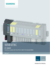
Siemens SIMATIC ET 200SP Manual (44 pages)
IM 155-6 PN ST interface module
Brand: Siemens
|
Category: I/O Systems
|
Size: 1.02 MB
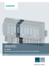
Siemens SIMATIC ET 200SP Manual (24 pages)
Digital output module
Brand: Siemens
|
Category: I/O Systems
|
Size: 0.79 MB
Table of Contents
-
Preface
4
-
Table of Contents
5
-
1 Guide to Documentation
6
-
2 Product Overview
8
-
Properties
8
-
-
3 Wiring
10
-
Terminal Assignment
10
-
Block Diagram
12
-
-
4 Parameter Assignment/Addressing
13
-
Parameters
13
-
Explanation of Parameters
14
-
Address Space
15
-
-
5 Interrupts/Diagnostics Alarms
16
-
Status and Fault Displays
16
-
Load Voltage Status
18
-
-
6 Technical Specifications
19
-
Parameter Data Record
22
-
Parameter Assignment and Structure of Parameter Data Record
22
-
-
Siemens SIMATIC ET 200SP Manual (24 pages)
DI 8x24VDC ST digital input module
Brand: Siemens
|
Category: Control Unit
|
Size: 0.68 MB
Table of Contents
-
Preface
3
-
Table of Contents
5
-
1 Documentation Guide
7
-
2 Product Overview
9
-
Properties of the DI 8X24Vdc ST
9
-
-
3 Connecting
11
-
Terminal Assignment
11
-
Schematic Circuit Diagram
12
-
-
4 Parameter Assignment/Addressing
13
-
Parameters
13
-
Declaration of Parameters
14
-
Address Space
14
-
-
5 Interrupt, Error and System Messages
15
-
Status and Error Displays
15
-
Diagnostic Messages
17
-
-
6 Technical Specifications
19
-
Parameter Data Record
21
-
Parameter Assignment and Structure of Parameter Data Record
21
-
-
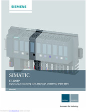
Siemens SIMATIC ET 200SP Manual (23 pages)
Brand: Siemens
|
Category: I/O Systems
|
Size: 1.15 MB
Table of Contents
-
Preface
4
-
Table of Contents
5
-
1 Guide to Documentation
6
-
2 Product Overview
8
-
Properties
8
-
-
3 Wiring
10
-
Wiring and Block Diagram
10
-
-
4 Parameter Assignment/Addressing
12
-
Parameters
12
-
Explanation of Parameters
13
-
Address Space
14
-
-
5 Interrupts/Diagnostics Alarms
15
-
Status and Fault Displays
15
-
Load Voltage Status
17
-
Interrupts
17
-
Diagnostics Alarms
17
-
-
6 Technical Specifications
18
-
Parameter Data Record
21
-
Parameter Assignment and Structure of Parameter Data Record
21
-
-
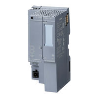
Siemens SIMATIC ET 200SP User Manual (21 pages)
server module
Brand: Siemens
|
Category: Controller
|
Size: 1.08 MB
Table of Contents
-
Preface
4
-
Table of Contents
5
-
1 Documentation Guide
6
-
2 Product Overview
8
-
Properties
8
-
-
3 Parameters/Address Space
9
-
Parameters
9
-
Explanation of the Parameters
10
-
Address Space
10
-
Input Data for Interface Modules with Maximum 12 I/O Modules
12
-
Input Data for Interface Modules with Maximum 32 I/O Modules
13
-
Input Data for Cpu/Interface Modules with Maximum 64 I/O Modules
14
-
Evaluating Feedback Voltage
15
-
-
4 Diagnostics Alarms
17
-
5 Technical Specifications
18
-
6 Parameter Data Record
19
-
Parameter Assignment and Structure of Parameter Data Record
19
-
Dimensional Drawing
21
-
Server Module
21
-
A.1 Server Module
21
-
-
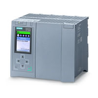
Siemens SIMATIC ET 200SP Configuration Manual (20 pages)
i/o
Brand: Siemens
|
Category: Controller
|
Size: 0.77 MB
Table of Contents
-
Warranty and Liability
2
-
Table of Contents
3
-
-
1 Task and Solution
4
-
Task Description
4
-
Possible Solutions
4
-
-
2 Fundamentals on «Shared Device
6
-
3 Configuration
8
-
Infrastructure Information
8
-
Configuring a «Shared Device
9
-
Configuration of Project 1
9
-
Configuration of Project 2
12
-
Adjusting the Real Time Settings
15
-
Compiling and Loading
17
-
Diagnostics with «Shared Device
18
-
-
4 References
20
-
5 History
20
Siemens SIMATIC ET 200SP Manual (33 pages)
Brand: Siemens
|
Category: Recording Equipment
|
Size: 0.66 MB
Siemens SIMATIC ET 200SP Product Information (24 pages)
Distributed I/O system
Brand: Siemens
|
Category: I/O Systems
|
Size: 0.41 MB
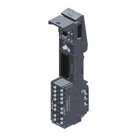
Siemens SIMATIC ET 200SP Product Information (10 pages)
Brand: Siemens
|
Category: I/O Systems
|
Size: 0.5 MB
Siemens SIMATIC ET 200SP Original Operating Instructions (6 pages)
Motor Starters
Brand: Siemens
|
Category: Controller
|
Size: 9.21 MB
Advertisement
Related Products
-
Siemens E-110
-
Siemens E-110-I
-
Siemens SIMATIC NET SCALANCE W760
-
Siemens SIMATIC NET SCALANCE W720
-
Siemens SIMATIC S7-CPs
-
Siemens SIMATIC NET SCALANCE S615
-
Siemens SIMATIC NET SCALANCE M826
-
Siemens SIMATIC NET SCALANCE XR-300M EEC Series
-
Siemens SIMATIC NET RUGGEDCOM RSG2288
-
Siemens SIMATIC NET RUGGEDCOM APE1808
Siemens Categories
Controller
Control Unit
Industrial Equipment
![]()
Washer
![]()
Switch
More Siemens Manuals
Содержание
- ET 200SP
- Информационные материалы
- Область применения
- Дизайн
- Функции
- Особенности
- Дальнейшая информация
ET 200SP
Информационные материалы
SIMATIC ET 200SP
Станция SIMATIC ET 200SP является масштабируемой и исключительно гибкой системой ввода-вывода, предназначенной для подключения к системе управления через PROFINET удаленных датчиков и исполнительных устройств.
SIMATIC ET 200SP монтируется на стандартную профильную шину и в большинстве случаев включает в свой состав:
- Интерфейсный модуль, поддерживающий обмен данными с ведущим устройством сети PROFINET по стандарту IEC 61158.
- До 64 периферийных модулей (зависит от типа интерфейсного модуля) устанавливаемых на базовые блоки в любом сочетании.
- Сервер модуль, завершающий внутреннюю шину станции.
Станция отличается простотой использования, имеет компактные размеры и требует для своей установки минимальных монтажных объемов. SIMATIC ET 200SP поддерживает обмен данными через сеть PROFINET, которая позволяет использовать более высокие скорости обмена данными и обеспечивает получение значительно более высокой производительности по сравнению с традиционными системами.
- Масштабируемая система ввода-вывода со степенью защиты IP20 для работы в сети PROFINET.
- Компактные размеры.
- Высочайшая степень удобства, обеспечиваемая:
- применением штекерных терминальных блоков для подключения соединительных проводников без использования инструмента;
- удобным доступом к контактам терминального блока, расположенным в колонки;
- наличием точек подключения измерительных приборов для выполнения необходимых измерений;
- понятная концепция маркировки компонентов станции, обеспечивающая безопасность ее обслуживания.
- Может комплектоваться дискретными и аналоговыми модулями ввода-вывода, а также другими модулями, находящимися в подготовке.
- Широкий спектр системных функций:
- Формирование индивидуальных потенциальных групп модулей без использования модулей контроля питания.
- Замена модулей во время работы станции («горячая» замена).
- Включение в работу с неполной конфигурацией для частичного ввода системы в эксплуатацию.
- Подключение внешних цепей без наличия периферийных модулей.
- Замена периферийных модулей без демонтажа их внешних цепей.
- Поддержка протокола PROFIenergy для реализации алгоритмов энергосбережения.
- Электронные таблички с набором идентификационных данных (I&M данные 0. 3).
- Поддержка функций обновления встроенного программного обеспечения для всех модулей станции.
- Управление конфигурацией станции из программы пользователя.
- Простая модернизация без реконфигурирования станции.
Область применения
SIMATIC ET 200SP является многофункциональной станцией систем ввода-вывода для широкого спектра промышленных применений. Станция обладает гибкими возможностями расширения и адаптации к требованиям решаемых задач. Она имеет степень защиты IP 20 и должна устанавливаться в шкафы управления.
Дизайн
Станция SIMATIC ET 200SP отличается гибкими возможностями масштабирования своих функциональных возможностей и позволяет использовать в своем составе до 64 периферийных модулей, способных обслуживать до 1024 дискретных каналов ввода-вывода.
Удобная конструкция станции позволяет существенно сокращать время выполнения монтажных работ. Станция состоит из базовых блоков со съемными терминальными коробками, съемных периферийных модулей с встроенной электроникой и интерфейсного модуля, подающего питание на всю внутреннюю электронику станции. Отдельные модули подачи питания на внутреннюю электронику не нужны. Периферийные модули и терминальные коробки можно менять во время работы станции. Механическое кодирование базовых блоков исключает возможность возникновения ошибок при замене периферийных модулей. Как результат обслуживание станции становится более безопасным.
Сетевые адаптеры (BA) позволяют выбирать необходимую технологию подключения станции SIMATIC ET 200SP к сети PROFINET. С помощью адаптера BA 2xRJ45 подключение к сети выполняется через два соединителя RJ45. Сетевой адаптер BA 2xFC позволяет подключать жилы и экраны сетевых кабелей непосредственно к своим контактам. Он обеспечивает наиболее высокую стойкость контактных соединений к механическим и электромагнитным воздействиям. Сетевые адаптеры могут быть легко заменены, что еще больше повышает удобство использования станции.
Станция SIMATIC ET 200SP оснащена новой системой цветовой и текстовой маркировки своих компонентов. Эта система включает в свой состав цветовые пластиковые накладки на терминальные коробки для выделения эквипотенциальных групп контактов, идентификационные этикетки для маркировки базовых блоков и периферийных модулей, а также этикетки для маркировки внешних цепей периферийных модулей.
Новое расположение пружинных контактов на терминальных коробках позволяет выполнять ручное подключение соединительных проводников без использования инструмента.
Интерфейсный модуль
Интерфейсный модуль подключает станцию SIMATIC ET 200SP к сети PROFINET и поддерживает обмен данными между ведущим сетевым устройством и периферийными модулями станции.
Подключение к сети выполняется через съемный сетевой адаптер.
Периферийные модули
Станция SIMATIC ET 200SP приблизительно на 50% уже, чем существующие сопоставимые системы ввода-вывода. При высоте около 117 мм она позволяет размещать 16-канальные модули ввода-вывода с однопроводным подключением внешних цепей (без контактов для подключения к шине AUX). При трехпроводном подключении внешних цепей 8-канальных периферийных модулей (с контактами для подключения к шине AUX) высота станции возрастает до 141 мм. Во всех случаях глубина станции приблизительно равна 75 мм.
Для сокращения размеров станции функции формирования потенциальных групп питания ее внешних цепей интегрированы в систему. Модули контроля питания (PM-E в станции ET 200S) для этой цели не нужны.
В настоящее время состав периферийных модулей представлен модулями ввода-вывода дискретных и аналоговых сигналов.
- Дискретные модули ввода-вывода
4-, 8- и 16-канальные модули для подключения датчиков и исполнительных устройств дискретного действия. - Аналоговые модули ввода-вывода
4-канальные модули для подключения аналоговых датчиков и исполнительных устройств.
Базовые блоки (BU)
обеспечивают поддержку электрических и механических соединений между модулями, снабжены терминальными коробками для подключения внешних цепей периферийных модулей. Подключение соединительных проводов и кабелей выполняется через пружинные контакты-защелки. Поддерживается возможность замены терминальной коробки базового блока.
Базовые блоки каждого типа выпускаются в 4 вариантах. Каждый базовый блок оснащен 16 (контакты 1 . 16) контактами для подключения внешних цепей периферийного модуля и 2 контактами для подключения цепи питания (контакты L+ и M).
Базовый блок типа A0 со светлой терминальной коробкой и механизмом деблокировки фиксации на профильной шине DIN
Содержит начальные участки внутренних шин (P1, P2 и AUX) и используется для формирования новой потенциальной группы модулей. Напряжение питания внешних цепей потенциальной группы подается на нижние контакты терминальной коробки. Эти контакты выделены красным (P1: +) и синим (P2: -) цветом. Длительно допустимый ток в цепи питания потенциальной группы не должен превышать 10 А.
Опционально светлые базовые блоки могут иметь терминальную коробку с 10 дополнительными электрически соединенными между собой контактами AUX (контакты 1A . 10A). Эта группа контактов может использоваться для подвода напряжения питания уровнем до =24 В или для соединения с цепью защитного заземления PE.
Базовый блок типа A0 с темной терминальной коробкой и механизмом деблокировки фиксации на профильной шине DIN
Этот базовый блок подобен базовому блоку со светлой терминальной коробкой, но содержит сквозные участки внутренних шин P1, P2 и AUX и предназначены для продолжения начатой ранее потенциальной группы.
Через контакты L+ и M напряжение питания может быть подключено к следующей потенциальной группе или к внешним цепям периферийного модуля.
Темные базовые блоки могут оснащаться терминальными коробками с 10 дополнительными контактами AUX.
Базовые блоки типа A1 для установки аналоговых модулей
Кроме 4 базовых блоков типа А0 существуют также базовые блоки типа А1 для установки аналоговых периферийных модулей.
Эти базовые блоки оснащены встроенным датчиком температурной компенсации, который может быть использован, например, в сочетании с периферийными модулями измерения температуры с помощью термопар.
Базовые блоки типа A1 могут оснащаться терминальными коробками с двумя дополнительными группами контактов. Каждая группа объединяет по 5 электрически связанных контактов (1B . 5B и 1C . 5C). Эти контакты могут использоваться для подключения индивидуального изолированного блока питания внешних цепей периферийного модуля. Уровень напряжения питания не должен превышать =24 В.
Руководства
Руководства по станции ET 200SP на английском, немецком, французском, испанском, итальянском или китайском языке могут быть загружены из интернета: SIMATIC Customer Support, http://www.siemens.com/automation/support.
Аксессуары
- Маркировочные этикетки
Для установки на фронтальные панели модулей ввода-вывода.
Рулон с 500 перфорированных этикеток для нанесения надписей с помощью стандартных термотрансферных принтеров. - Идентификационные этикетки
Для идентификации сетевого адаптера, интерфейсного модуля, базовых блоков и периферийных модулей. После нанесения идентификационной информации устанавливаются на верхнюю часть корпуса соответствующего элемента станции.
10 листов, по 16 этикеток на лист, нанесение надписей с помощью стандартных термотрансферных принтеров. - Элементы подключения экрана
Устанавливаются в нижней части базового блока и имеют низкоомное соединение с цепью защитного заземления PE (заземленной профильной шиной). Позволяют подключать экраны соединительных кабелей к цепи защитного заземления.
Поставляются в виде комплекта с 5 элементами заземления и 5 терминалами для подключения экранов соединительных кабелей. - Пластиковые цветные рамки
С помощью пластиковых цветных рамок эквипотенциальные группы контактов терминальных коробок базовых блоков могут выделяться определенным цветом. Эти рамки устанавливаются на фронтальную часть терминальной коробки и имеют три варианта исполнений:- Рамка для цветной маркировки 16 контактов подключения внешних цепей периферийного модуля. Выбор элемента цветной маркировки производится по цветовому коду (CC — color code), который нанесен на фронтальную панель каждого периферийного модуля и на элемент цветной маркировки контактов. Комплект из 10 рамок.
- Рамка для цветной кодировки 10 контактов AUX терминальных коробок базовых блоков типа A0 красным, синим или желтым/ зеленым цветом. Комплект из 10 рамок.
- Рамка для цветной маркировки 10 дополнительных контактов (2 группы по 5 контактов) терминальных коробок базовых блоков типа A1 красным и синим цветом. Комплект из 10 рамок.
Конструктивные особенности
Интерфейсный модуль, базовые блоки и сервер модуль станции устанавливаются на стандартную профильную шину DIN 35х 15х 7.5 мм или 35х 15х 15 мм. Внешние цепи могут подключаться к контактам терминальных коробок базовых блоков без предварительной установки периферийных модулей. Такая конструкция позволяет выполнять быструю замену модулей станции без демонтажа их внешних цепей и сводить к минимуму время простоя производственного оборудования. Замена модулей может производиться без отключения питания станции.
Первая установка периферийного модуля на базовый блок автоматически сопровождается выполнением операции механического кодирования. В дальнейшем да данный базовый блок можно устанавливать только периферийные модули такого же типа. Это исключает возможность возникновения ошибок при замене периферийных модулей.
При конфигурировании станции ET 200SP необходимо учитывать только несколько правил:
Ограничения на расширение
В зависимости от типа используемого интерфейсного модуля в одну станцию ET 200SP можно устанавливать до 64 периферийных модулей.
- Следом за интерфейсным модулем станции должен обязательно устанавливаться светлый базовый блок.
- Внешние цепи периферийных модулей одной потенциальной группы должны потреблять ток не более 10 А.
- В пределах одной потенциальной группы периферийные модули могут размещаться в любом порядке.
Функции
Режимы работы
Через сеть PROFINET ведущее сетевое устройство может получать доступ к периферийным модулям станции ET 200SP по аналогии с доступом к модулям системы локального ввода-вывода.
Управление обменом данными выполняет интерфейсный модуль ведущего сетевого устройства и интерфейсный модуль IM 155-6 станции ET 200SP. Для повышения стойкости к воздействию помех обмен данными выполняется через экранированные кабели.
Исчерпывающий набор легко программируемых функций поканальной диагностики в сочетании с представлением результатов диагностики в виде текстовых сообщений позволяет выполнять быстрый поиск и локализацию неисправностей, сводить время простоя производственного оборудования к минимуму.
Конфигурирование, настройка параметров и диагностика
Конфигурирование и настройка параметров станции ET 200SP выполняется с помощью пакета STEP 7 или с помощью инструментальных средств используемого контроллера сети PROFINET.
В зависимости от состава используемых периферийных модулей станция позволяет получать детальную диагностическую информацию о своих состояниях.
Особенности
- Свободный выбор необходимого варианта подключения к сети PROFINET и использованием сетевого адаптера соответствующего типа.
- Подключение соединительных проводников к контактам терминальных блоков без использования инструмента.
- Улучшенный доступ к контактам терминальных блоков, обеспечиваемый новым вариантом расположения пружинных контактов-защелок.
- Высокая наглядность, обеспечиваемая применением маркировочных этикеток и элементов цветовой маркировки компонентов станции.
- Надежное заземление экранов сетевых и соединительных кабелей.
- До 64 периферийных модулей на станцию (зависит от типа интерфейсного модуля).
- Минимальные монтажные объемы, необходимые для установки станции в шкафу управления.
- Возможность установки в стандартные 800 мм шкафы управления.
- Высокая скорость обмена данными через PROFINET.
- «Горячая» замена периферийных модулей и терминальных коробок базовых блоков во время работы станции.
- Встроенная поддержка протокола PROFIenergy, реализация алгоритмов энергосбережения.
- Управление конфигурацией станции из программы пользователя.
Дальнейшая информация
Дополнительная информация
Инструментарий SIMATIC Selection Tool
Необходимые информационные материалы могут быть загружены из интернета по адресу:
Источник
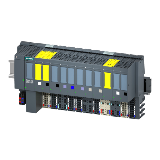
- Manuals
- Brands
- Siemens Manuals
- I/O Systems
- SIMATIC ET 200SP
- Equipment manual
-
Contents
-
Table of Contents
-
Bookmarks
Quick Links
Related Manuals for Siemens SIMATIC ET 200SP
Summary of Contents for Siemens SIMATIC ET 200SP
-
Page 1
Ďte… -
Page 2
Digital input module F-DI 8x24VDC HF (6ES7136-6BA01-0CA0) Preface Documentation guide SIMATIC Product overview Connecting ET 200SP Digital input module F-DI 8x24VDC HF Parameters/address space (6ES7136-6BA01-0CA0) Applications of the F-I/O module Equipment Manual Interrupts/diagnostic messages Technical specifications Response times 10/2021 A5E50578307-AA… -
Page 3
Note the following: WARNING Siemens products may only be used for the applications described in the catalog and in the relevant technical documentation. If products and components from other manufacturers are used, these must be recommended or approved by Siemens. Proper transport, storage, installation, assembly, commissioning, operation and maintenance are required to ensure that the products operate safely and without any problems. -
Page 4: Preface
Standards You can find a dated reference to the respective standards in the certificate (https://support.industry.siemens.com/cs/ww/en/view/57141281) or in the EC Declaration of Conformity (https://support.industry.siemens.com/cs/ww/en/view/71764057) on the F- module. Certified versions The certified product and firmware versions are specified in Annex 1 of the report on the TÜV…
-
Page 5
The operators of systems with safety-related characteristics must adhere to specific operational safety requirements. The supplier is also obliged to comply with special product monitoring measures. Siemens informs system operators in the form of personal notifications about product developments and properties which may be or become important issues in terms of operational safety. -
Page 6
Siemens’ products and solutions undergo continuous development to make them more secure. Siemens strongly recommends that product updates are applied as soon as they are available and that the latest product versions are used. Use of product versions that are no longer supported, and failure to apply the latest updates may increase customers’ exposure to cyber threats. -
Page 7: Table Of Contents
Table of contents Preface …………………………3 Documentation guide ……………………..9 Product overview ……………………..15 Properties …………………….. 15 Connecting ……………………….19 Wiring and block diagram ………………..19 Parameters/address space ……………………21 Parameters ……………………21 Explanation of parameters ………………..24 4.2.1 F-parameters ……………………24 4.2.1.1 F-parameters ……………………
-
Page 8
Table of contents Interrupts/diagnostic messages ………………….53 Status and error display ………………… 53 Interrupts …………………….. 56 Diagnostic messages ………………….58 Value status ……………………63 Technical specifications ……………………65 Response times ………………………. 69 Digital input module F-DI 8x24VDC HF (6ES7136-6BA01-0CA0) Equipment Manual, 10/2021, A5E50578307-AA… -
Page 9
This arrangement enables you to access the specific content you require. Basic information The System Manual and Getting Started describe in detail the configuration, installation, wiring and commissioning of the SIMATIC ET 200SP distributed I/O system. The STEP 7 online help supports you in the configuration and programming. Device information Product manuals contain a compact description of the module-specific information, such as properties, wiring diagrams, characteristics and technical specifications. -
Page 10
You can download the product information free of charge from the Internet (https://support.industry.siemens.com/cs/us/en/view/73021864). Manual Collection ET 200SP The Manual Collection contains the complete documentation on the SIMATIC ET 200SP distributed I/O system gathered together in one file. You can find the Manual Collection on the Internet (https://support.automation.siemens.com/WW/view/en/84133942). -
Page 11
• Manuals, characteristics, operating manuals, certificates • Product master data You can find «mySupport» — CAx data on the Internet (https://support.industry.siemens.com/my/ww/en/CAxOnline). Application examples The application examples support you with various tools and examples for solving your automation tasks. Solutions are shown in interplay with multiple components in the system — separated from the focus on individual products. -
Page 12
You can find the SIMATIC Automation Tool on the Internet (https://support.industry.siemens.com/cs/ww/en/view/98161300). PRONETA SIEMENS PRONETA (PROFINET network analysis) allows you to analyze the plant network during commissioning. PRONETA features two core functions: • The topology overview automatically scans the PROFINET and all connected components. -
Page 13
Documentation guide SINETPLAN SINETPLAN, the Siemens Network Planner, supports you in planning automation systems and networks based on PROFINET. The tool facilitates professional and predictive dimensioning of your PROFINET installation as early as in the planning stage. In addition, SINETPLAN supports you during network optimization and helps you to exploit network resources optimally and to plan reserves. -
Page 14: Product Overview
Product overview Properties Article number 6ES7136-6BA01-0CA0 View of the module ① Module type and name ⑦ Function class ② LED for diagnostics ⑧ Color coding module type ③ 2D matrix code ⑨ Function and firmware version ④ Wiring diagram ⑩ Color code for selecting the color identification labels ⑤…
-
Page 15
Product overview 2.1 Properties Properties The module has the following technical properties: • Fail-safe digital module • PROFIsafe • RIOforFA-Safety • PROFIsafe address type 2 • 8 inputs (SIL3/Cat.3/PLd) or 4 inputs (SIL3/Cat.4/PLe) • 8 outputs for sensor supply • Use of various interconnection types (1oo1, 1oo2) is possible •… -
Page 16
• Shield connection • Electronic coding element as replacement part (part number 6ES7193-6EF00-1AA0) For more information on accessories, refer to the system manual ET 200SP Distributed I/O System (https://support.industry.siemens.com/cs/ww/en/view/58649293). Digital input module F-DI 8x24VDC HF (6ES7136-6BA01-0CA0) Equipment Manual, 10/2021, A5E50578307-AA… -
Page 17: Connecting
This section includes the block diagram of the digital input module F-DI 8×24VDC HF with the terminal assignment. You can find information on wiring the BaseUnit in the ET 200SP Distributed I/O System (https://support.industry.siemens.com/cs/ww/en/view/58649293) system manual. Digital input module F-DI 8x24VDC HF (6ES7136-6BA01-0CA0) Equipment Manual, 10/2021, A5E50578307-AA…
-
Page 18
Connecting 3.1 Wiring and block diagram Block diagram The following figure shows the pin assignment of the digital input module F-DI 8×24VDC HF on the BaseUnit BU type A0. ① Backplane bus interface Internal sensor supply, channel n ② Input electronics P1, P2, Internal self-configuring voltage buses Connection to left (dark BaseUnit) -
Page 19: Parameters/Address Space
Parameters/address space Parameters Parameter for F-DI 8x24VDC HF WARNING Diagnostics functions should be activated or deactivated in accordance with the application, see section Applications of the F-I/O module (Page 37). The following parameters are possible: Table 4- 1 Adjustable parameters Parameters Value range Default…
-
Page 20
Parameters/address space 4.1 Parameters Parameters Value range Default Parameter Scope reassignment in F-I/O DB name — Is proposed by the F- Module system DI parameters: Sensor supply Sensor supply n Short-circuit test Enable Channel • Disable • Enable Time for short-circuit test 0.5 ms to 2 s 4.2 ms Channel… -
Page 21
Parameters/address space 4.1 Parameters Parameters Value range Default Parameter Scope reassignment in Input delay 3.2 ms Channel • 0.4 ms • 0.8 ms • 1.6 ms • 3.2 ms • 6.4 ms • 10.0 ms • 12.8 ms • 20 ms The provided value range depends on the parameter assignment… -
Page 22: Explanation Of Parameters
Information on the F-parameters for the F-monitoring time, the PROFIsafe addressing (F- source address, F-destination address) and the F-I/O DB can be found in the manual SIMATIC Safety — Configuring and Programming (https://support.industry.siemens.com/cs/ww/en/view/54110126). See also S7 Distributed Safety — Configuring and Programming (https://support.industry.siemens.com/cs/ww/en/view/22099875)
-
Page 23: Reintegration After Channel Fault
Parameters/address space 4.2 Explanation of parameters 4.2.1.3 Reintegration after channel fault Use this parameter to select how the channels of the fail-safe module are reintegrated after a fault. Use on S7-300/400 F-CPUs This parameter is always set to «Adjustable» when you use the fail-safe module in S7-300/400 F-CPUs.
-
Page 24: Parameters Of The Sensor Supply
Parameters/address space 4.2 Explanation of parameters 4.2.2 Parameters of the sensor supply 4.2.2.1 Short-circuit test Here you activate the short-circuit detection for the channels of the F-module for which an internal sensor supply is set. The short-circuit test can always be performed when you use simple switches which do not have an own power supply.
-
Page 25: Time For Short-Circuit Test
Parameters/address space 4.2 Explanation of parameters 4.2.2.2 Time for short-circuit test Function When the short-circuit test is enabled, the corresponding sensor supply is switched off for the configured time. If the module does not detect a «0» signal at the input within the assigned time, a diagnostic message is generated.
-
Page 26: Parameters Of The Channel Pairs
Parameters/address space 4.2 Explanation of parameters 4.2.3 Parameters of the channel pairs 4.2.3.1 Sensor evaluation Overview Select the type of sensor evaluation with the «Sensor evaluation» parameter: • 1oo1 evaluation • 1oo2 evaluation, equivalent • 1oo2 evaluation, non-equivalent 1oo1 evaluation The sensor uses only one input channel for the 1oo1 evaluation.
-
Page 27: Discrepancy Behavior
Parameters/address space 4.2 Explanation of parameters 4.2.3.2 Discrepancy behavior Function For the «Discrepancy behavior», you assign the value that is supplied to the safety program in the F-CPU during a discrepancy between two relevant input channels, which means while discrepancy time is running. You assign the discrepancy behavior as follows: •…
-
Page 28: Discrepancy Time
Parameters/address space 4.2 Explanation of parameters 4.2.3.3 Discrepancy time Function You can set the discrepancy time for each channel pair. Requirements You have assigned the following: • «Sensor evaluation»: «1oo2 evaluation, equivalent» or «1oo2 evaluation, non-equivalent» In most cases, a discrepancy time is started, but does not fully expire because the signal differences are cleared within a short time.
-
Page 29: Reintegration After Discrepancy Error
Parameters/address space 4.2 Explanation of parameters 4.2.3.4 Reintegration after discrepancy error Function This parameter specifies the criteria for when a discrepancy error is regarded as corrected, thus enabling reintegration of the relevant input channels. The following parameter assignment options are available: •…
-
Page 30: Parameters Of The Channels
For S7-300/400 F-CPUs you set the corresponding property at the F-I/O DB by means of the ACK_NEC tag. For detailed information about the F-I/O DB, refer to the SIMATIC Safety – Configuring and Programming (https://support.industry.siemens.com/cs/ww/en/view/54110126) manual. Digital input module F-DI 8x24VDC HF (6ES7136-6BA01-0CA0) Equipment Manual, 10/2021, A5E50578307-AA…
-
Page 31: Sensor Supply
(see section «Electromagnetic compatibility» in the system manual ET 200SP distributed I/O system (https://support.industry.siemens.com/cs/ww/en/view/58649293)). Adapt the input delay or use shielded signal lines in order to prevent possible passivation of the fail-safe digital inputs and switch-off of the sensor supply.
-
Page 32: Chatter Monitoring
Parameters/address space 4.2 Explanation of parameters 4.2.4.5 Chatter monitoring Function Chatter monitoring is a process control function for digital input signals. It detects and reports unusual signal sequences in the process with 1oo1 evaluation, for example, an input signal fluctuating between «0» and «1» too frequently. The occurrence of such signal characteristics is an indication of faulty sensors or process control instability.
-
Page 33: Number Of Signal Changes
Parameters/address space 4.3 Address space 4.2.4.6 Number of signal changes Defines the number of signal changes after whose sequence a chatter error is to be reported. 4.2.4.7 Monitoring window Sets the time for the monitoring window of chatter monitoring. You can set times of 1 s to 100 s in whole seconds for the monitoring window. If you parameterize 0 s, the monitoring window is 0.5 s long.
-
Page 34
1oo2 evaluation of the sensors, you must only access the low-order channel in the safety program, in this example DI Additional information For detailed information about F-I/O access, refer to the SIMATIC Safety – Configuring and Programming (https://support.industry.siemens.com/cs/ww/en/view/54110126) manual. See also S7 Distributed Safety — Configuring and Programming (https://support.industry.siemens.com/cs/ww/en/view/22099875) -
Page 35: Applications Of The F-I/O Module
Applications of the F-I/O module Applications of the electronic module Selecting the application The diagram below supports you in selecting the application that suits your fail-safe requirements. In the following sections, you will learn how to wire the F-module, the specific parameters you must assign in STEP 7 Safety and the errors that are detected.
-
Page 36
Information on the safety-oriented use of sensors can be found in the section Requirements for sensors and actuators for fail-safe modules and fail-safe motor starters in the system manual ET 200SP Distributed I/O System (https://support.industry.siemens.com/cs/ww/en/view/58649293). Digital input module F-DI 8x24VDC HF (6ES7136-6BA01-0CA0) Equipment Manual, 10/2021, A5E50578307-AA… -
Page 37: Application 1: Safety Mode Sil3/Cat.3/Pld
Applications of the F-I/O module 5.2 Application 1: Safety mode SIL3/Cat.3/PLd Application 1: Safety mode SIL3/Cat.3/PLd Wiring The wiring is carried out on the matching BaseUnit. Sensor supply The sensor supply can be internal or external. Wiring diagram – connecting one sensor via one channel Per process signal, one sensor is connected via one channel (1oo1 evaluation).
-
Page 38
Applications of the F-I/O module 5.2 Application 1: Safety mode SIL3/Cat.3/PLd WARNING To achieve SIL3/Cat.3/PLd using this wiring, you must use a qualified sensor. WARNING To achieve SIL3/Cat.3/PLd with this wiring, you have to route the cables cross-circuit proof and apply the positive opening operation principle for the sensor. Parameter assignment Assign the following parameters for the corresponding channel: Table 5- 2… -
Page 39
Applications of the F-I/O module 5.2 Application 1: Safety mode SIL3/Cat.3/PLd Fault detection The following table presents fault detection according to the sensor supply and the parameter assignment for the short-circuit test: Table 5- 3 Fault detection Fault Fault detection Internal sensor supply Internal sensor supply External sensor… -
Page 40: Application 2: Safety Mode Sil3/Cat.3/Ple
Applications of the F-I/O module 5.3 Application 2: Safety mode SIL3/Cat.3/PLe Application 2: Safety mode SIL3/Cat.3/PLe Assigning inputs to each other The digital input module F-DI 8×24VDC HF has 8 fail-safe inputs, DI to DI (SIL3). You can combine two of these inputs each to one input. You can combine the following inputs: •…
-
Page 41
Applications of the F-I/O module 5.3 Application 2: Safety mode SIL3/Cat.3/PLe Figure 5-3 A two-channel sensor connected via two channels, internal and external sensor supply WARNING To achieve SIL3/Cat.3/PLe using this wiring, you must use a suitably qualified sensor. Wiring diagram — connecting two one-channel sensors equivalent via two channels Per process signal, two one-channel sensors, which record the same process value, are connected equivalent via two channels to two inputs of the F-module (1oo2 evaluation). -
Page 42
Applications of the F-I/O module 5.3 Application 2: Safety mode SIL3/Cat.3/PLe Figure 5-4 Two one-channel sensors connected via two channels, internal and external sensor supply WARNING To achieve SIL3/Cat.3/PLe using this wiring, you must use a qualified sensor. Digital input module F-DI 8x24VDC HF (6ES7136-6BA01-0CA0) Equipment Manual, 10/2021, A5E50578307-AA… -
Page 43
Applications of the F-I/O module 5.3 Application 2: Safety mode SIL3/Cat.3/PLe Parameter assignment Assign the following parameters for the corresponding channel: Table 5- 4 Parameter assignment Parameter Channel with internal sensor Channel with external sensor supply supply Sensor evaluation 1oo2 evaluation, equivalent Sensor supply Sensor supply n External sensor supply*… -
Page 44: Application 3: Safety Mode Sil3/Cat.4/Ple
Applications of the F-I/O module 5.4 Application 3: Safety mode SIL3/Cat.4/PLe Application 3: Safety mode SIL3/Cat.4/PLe Assigning inputs to each other The digital input module F-DI 8×24VDC HF has 8 fail-safe inputs, DI to DI (SIL3). You can combine two of these inputs each to one input. You can combine the following inputs: •…
-
Page 45: Application 3.1: Safety Mode Sil3/Cat.4/Ple
Applications of the F-I/O module 5.4 Application 3: Safety mode SIL3/Cat.4/PLe 5.4.1 Application 3.1: Safety mode SIL3/Cat.4/PLe Wiring diagram — connecting a two-channel sensor equivalent via two channels Per process signal, a two-channel sensor is connected equivalent via two channels to two inputs of the F-module (1oo2 evaluation).
-
Page 46
Applications of the F-I/O module 5.4 Application 3: Safety mode SIL3/Cat.4/PLe Wiring diagram — connecting two one-channel sensors equivalent via two channels Per process signal, two one-channel sensors, which record the same process value, are connected equivalent via two channels to two inputs of the F-module (1oo2 evaluation). Supply the sensors from two different internal sensor supplies or from an internal and an external sensor supply. -
Page 47
Applications of the F-I/O module 5.4 Application 3: Safety mode SIL3/Cat.4/PLe Parameter assignment Assign the following parameters for the corresponding channel: Table 5- 6 Parameter assignment Parameter Channel with internal Channel with external sensor supply sensor supply* Sensor evaluation 1oo2 evaluation, equivalent Sensor supply Sensor supply n External sensor supply**… -
Page 48: Application 3.2: Safety Mode Sil3/Cat.4/Ple
Applications of the F-I/O module 5.4 Application 3: Safety mode SIL3/Cat.4/PLe 5.4.2 Application 3.2: Safety mode SIL3/Cat.4/PLe Wiring diagram – connecting a non-equivalent sensor Per process signal, a non-equivalent sensor is connected to two inputs of the F-module (1oo2 evaluation). You can supply the sensor via an internal or external sensor supply.
-
Page 49
Applications of the F-I/O module 5.4 Application 3: Safety mode SIL3/Cat.4/PLe Wiring diagram — connecting two one-channel sensors non-equivalent via two channels Per process signal, two one-channel sensors, which record the same process value, are connected non-equivalent via two channels to two inputs of the F-module (1oo2 evaluation). Any sensor supply of the module can be assigned to each input. -
Page 50
Applications of the F-I/O module 5.4 Application 3: Safety mode SIL3/Cat.4/PLe Parameter assignment Assign the following parameters for the corresponding channel: Table 5- 8 Parameter assignment Parameter Channel with internal sensor supply Channel with external sensor supply Sensor evaluation 1oo2 evaluation, non-equivalent Sensor supply Sensor supply n External sensor supply*… -
Page 51: Interrupts/Diagnostic Messages
Interrupts/diagnostic messages Status and error display LED display The following figure shows you the LED display of the F-DI 8x24VDC HF. ① DIAG (green/red) ② Channel status (green) ③ Channel error (red) ④ PWR (green) Figure 6-1 LED display Meaning of the LED displays The following tables explain the meaning of the status and error displays.
-
Page 52
Interrupts/diagnostic messages 6.1 Status and error display DIAG LED Table 6- 1 DIAG LED fault display DIAG Meaning Backplane bus supply of the ET 200SP not okay Module parameters not configured Flashing Module parameters configured and no module diagnostics • Module parameters configured and module diagnostics Flashing •… -
Page 53
Interrupts/diagnostic messages 6.1 Status and error display Channel status/DIAG/channel fault LED Table 6- 3 Status display of the LED channel status/DIAG/channel fault Channel DIAG Channel Meaning status fault The PROFIsafe address does not match the PROFIsafe address of the configuration or there is a module-wide error. See section All On Flashin Interrupts (Page 56) -
Page 54: Interrupts
Interrupts/diagnostic messages 6.2 Interrupts Interrupts Introduction The fail-safe digital input module F-DI 8×24VDC HF supports diagnostic interrupts. Diagnostic interrupt The F-module generates a diagnostic interrupt for each diagnostic message described in section Diagnostic messages (Page 58). The following list provides you with an overview of the diagnostic interrupts of the F-module. The diagnostic interrupts are assigned either to one channel or the entire F-module.
-
Page 55
Interrupts/diagnostic messages 6.2 Interrupts • Invalid/inconsistent firmware present • Diagnostic queue overflow • Undertemperature • Supply voltage too high • Supply voltage too low • F-module error (0x032F) Channel-wide diagnostic interrupts • Discrepancy failure, channel status 0/0 • Discrepancy failure, channel status 0/1 •… -
Page 56: Diagnostic Messages
Once the fault is eliminated, the F-module must be reintegrated in the safety program. For additional information on passivation and reintegration of F-I/O, refer to the SIMATIC Safety – Configuring and Programming (https://support.industry.siemens.com/cs/ww/en/view/54110126) manual. Table 6- 5 Diagnostics messages of the F-DI 8x24VDC HF…
-
Page 57
Interrupts/diagnostic messages 6.3 Diagnostic messages Diagnostic message Fault Meaning Remedy code Parameter F_CRC_Length The PROFIsafe driver has detected a does not match the discrepancy in the CRC length. generated values Version of F parameter set The PROFIsafe driver has detected an incorrect incorrect version of the F-parameters or an invalid F_Block_ID. -
Page 58
Interrupts/diagnostic messages 6.3 Diagnostic messages Diagnostic message Fault Meaning Remedy code Diagnostic queue overflow Overflow of the diagnostic memory. Not Eliminate the previously reported error. all pending diagnostics could be sent. This error can result in deactivation of the module up to switching on/off of the power supply. -
Page 59
Interrupts/diagnostic messages 6.3 Diagnostic messages Diagnostic message Fault Meaning Remedy code Overload or internal sensor Possible causes: • Eliminate the overload. supply short-circuit to ground • The internal sensor supply is short- • Eliminate the short-circuit in the circuited to ground. process wiring. -
Page 60
Generally applicable information on diagnostics For information on diagnostics which apply to all F-modules (e.g. reading out the diagnostic functions, passivation of channels), refer to the SIMATIC Safety — Configuring and Programming (https://support.industry.siemens.com/cs/ww/en/view/54110126) manual. See also S7 Distributed Safety — Configuring and Programming (https://support.industry.siemens.com/cs/ww/en/view/22099875) -
Page 61: Value Status
You can find the assignment in section Address space (Page 35). Reference A detailed description of the evaluation and processing of the value status can be found in the SIMATIC Safety – Configuring and Programming (https://support.industry.siemens.com/cs/ww/en/view/54110126) manual. Digital input module F-DI 8x24VDC HF (6ES7136-6BA01-0CA0) Equipment Manual, 10/2021, A5E50578307-AA…
-
Page 62
Technical specifications Technical specifications of F-DI 8×24VDC HF The following table shows the technical specifications as of 10/2021. You can find a data sheet including updated technical specifications on the Internet (https://support.industry.siemens.com/cs/ww/en/pv/6ES7136-6BA01-0CA0/td?dl=en). Article number 6ES7136-6BA01-0CA0 General information Product type designation… -
Page 63: Technical Specifications
Technical specifications Article number 6ES7136-6BA01-0CA0 Power loss Power loss, typ. Address area Address space per module 7 byte; S7-300/400F CPU, 6 byte • Inputs 5 byte; S7-300/400F CPU, 4 byte • Outputs Hardware configuration Automatic encoding • Electronic coding element type F Digital inputs Number of digital inputs Source/sink input…
-
Page 64
Technical specifications Article number 6ES7136-6BA01-0CA0 Yes; green PWR LED • Monitoring of the supply voltage (PWR-LED) Yes; green LED • Channel status display Yes; red LED • for channel diagnostics Yes; green/red DIAG LED • for module diagnostics Potential separation Potential separation channels •… -
Page 65
Technical specifications Dimension drawing See the Equipment Manual ET 200SP BaseUnits (https://support.industry.siemens.com/cs/ww/en/view/59753521). Digital input module F-DI 8x24VDC HF (6ES7136-6BA01-0CA0) Equipment Manual, 10/2021, A5E50578307-AA… -
Page 66
F-DI 8×24VDC HF are included in the calculation of the response time of the F-system. To do this, use the SIMATIC STEP7 response time table (https://support.industry.siemens.com/cs/ww/en/view/93839056). WARNING If you have configured the digital input module F-DI 8x24VDC HF (6ES7136-6BA00-0CA0) in… -
Page 67: Response Times
Response times Maximum response time in an error-free scenario (worst case delay time, WCDT) for 1oo2 evaluation. The following formula applies to a sensor supply without short-circuit test: Maximum response time (T ) = 2 * T + Input delay+ Discrepancy time* WCDT cycle The following formula applies to a sensor supply with short-circuit test:…
-
Page 68
Response times x = Sensor supply T1x = Time for short-circuit test T2x = Startup time of sensor after short-circuit test n = Number of sensor supplies with activated short-circuit test The following section provides two examples for the calculation of the maximum response time to external short-circuits at an F-DI 8×24VDC HF, depending on the parameter assignment. -
Page 69
Response times Maximum response time for discrepancy error for 1oo2 evaluation (one fault delay time, OFDT) Maximum response time (T ) = 2 * T + Input delay + 2 * max (T1p + T2p, T1s + T2s) + OFDT cycle Discrepancy time T1p = Time for short-circuit test (sensor 1)