-
Contents
-
Table of Contents
-
Troubleshooting
-
Bookmarks
Related Manuals for Toshiba Satellite A300 series
Summary of Contents for Toshiba Satellite A300 series
-
Page 1
Toshiba Personal Computer Satellite A300 Maintenance Manual TOSHIBA CORPORATION File Number 960-Q08 Satellite A300 Maintenance Manual (960-Q08) -
Page 2
The information presented in this manual has been reviewed and validated for accuracy. The included set of instructions and descriptions are accurate for the Satellite A300 Series at the time of this manual’s production. However, succeeding computers and manuals are subject to change without notice. -
Page 3
NOTE: “Note” contains general information that relates to your safe maintenance service. Improper repair of the computer may result in safety hazards. Toshiba requires service technicians and authorized dealers or service providers to ensure the following safety precautions are adhered to strictly. -
Page 4: Overview
The manual is divided into the following parts: Chapter 1 Hardware Overview describes the Satellite A300 system unit and each FRU. Chapter 2 Troubleshooting Procedures explains how to diagnose and resolve FRU problems. Chapter 3 Test and Diagnostics describes how to perform test and diagnostic operations for maintenance service.
-
Page 5
Text that you are instructed to type in is shown in the boldface type below: DISKCOPY A: B: The display Text generated by the computer that appears on its display is presented in the typeface below: Format complete System transferred Satellite A300 Maintenance Manual (960-Q08) -
Page 6: Table Of Contents
Troubleshooting ………………….1 Troubleshooting Flowchart………………..3 Power Supply Troubleshooting ………………7 Procedure 1 Power Status Check …………..7 Procedure 2 Error Code Check …………..9 Procedure 3 Connection Check…………..10 Procedure 4 Charging Check ……………11 Procedure 5 Replacement Check …………..12 Satellite A300 Maintenance Manual (960-Q08)
-
Page 7
Diagnostic Test Program Execution Check ……31 Procedure 2 Connector Check and Replacement Check……32 Touch pad Troubleshooting ………………33 Procedure 1 Diagnostic Test Program Execution Check ……33 Procedure 2 Connector Check and Replacement Check……34 Satellite A300 Maintenance Manual (960-Q08) -
Page 8
Fingerprint Troubleshooting ………………49 Procedure 1 Diagnostic Test Program Execution Check ……49 Procedure 2 Connector Check and Replacement Check……49 2.17 Bluetooth Troubleshooting ………………50 Procedure 1 Diagnostic Test Program Execution Check ……50 Procedure 2 Connector Check and Replacement Check……50 Satellite A300 Maintenance Manual (960-Q08) -
Page 9
Write DMI Information……………………………………………3-55 3.18 Log Utilities ………………….3-57 3.18.1 Operations…………………………………………………………3-57 ..3.19 System Configuration ………………..3-59 3.20 Running Test Edit Item……………….. 3-60 3.20.1 Function Description………………………………………………3-60 ..3.20.2 Operation Description……………………………………………3-60 3.21 Tests an Operation ………………3-62 Common Satellite A300 Maintenance Manual (960-Q08) -
Page 10
Optical disk drive………………… 4-26 4.10 Display assembly ………………… 4-28 4.11 Bluetooth assembly………………..4-33 4.12 Cover assembly………………….4-38 4.13 Touch pad……………………. 4-40 4.14 Audio board ………………….4-40 4.15 Fingerprint board ………………… 4-41 4.16 USB board…………………… 4-42 4.17 System board………………….4-45 Satellite A300 Maintenance Manual (960-Q08) -
Page 11
4.18 CPU……………………..4-47 4.19 VGA heat sink………………….4-50 4.20 LCD unit / FL inverter ………………… 4-52 Satellite A300 Maintenance Manual (960-Q08) -
Page 12
Appendix C Pin Assignments…………………C-1 Appendix D Keyboard Scan/Character Codes …………..D-1 Appendix E Key Layout…………………E-1 Appendix F Wiring Diagrams……………….. F-1 Appendix G BIOS Rewrite Procedures …………….G-1 Appendix H EC/KBC Rewrite Procedures……………. H-1 Appendix I Reliability………………….I-1 Satellite A300 Maintenance Manual (960-Q08) -
Page 13
Satellite A300 Maintenance Manual (960-Q08) -
Page 14: Chapter 1 Hardware Overview
Chapter 1 Hardware Overview Satellite A300 Maintenance Manual (960-Q08)
-
Page 15: Chapter 1 Hardware Overview
Chapter 1 Hardware Overview Hardware Overview Satellite A300 Maintenance Manual (960-Q08)
-
Page 16: System Block Diagram
TFT Color Display…………………..19 1.6.1 LCD Module ………………19 1.6.2 FL Inverter Board……………….22 1.6.3….. FL Inverter Board………………………………………………… … 22 Power Supply …………………..24 Batteries ……………………25 1.8.1 Main Battery……………….25 1.8.2 Battery Charging Control ……………26 1.8.3 RTC battery ………………..27 AC Adapter ……………………28 Satellite A300 Maintenance Manual (960-Q08)
-
Page 17
Table 1-7 Battery specifications………………25 Table 1-8 Time required for charges of main battery …………26 Table 1-9 Data preservation time ………………26 Table 1-10 Time required for charges of RTC battery…………27 Table 1-11 AC adapter specifications …………….28 Satellite A300 Maintenance Manual (960-Q08) -
Page 18: Features
Chapter 1 Hardware Overview Features Features The Satellite A300 series are 2 spindle PCs running Intel® Core™2 Duo Processor T8100 or higher. Intel® Core™2 Duo Processor T9300 or higher. Intel® Pentium Dual Processor T2330or higher. Intel® Celeron 540 Processor or higher.
-
Page 19
Supported via a RGB connector. θ Keyboard Toshiba Standard keyboard with 86-88 keys (desktop-style), Support Windows keys & Application keys. (Toshiba standard layout) Standard pitch, 2.5mm travel length. Multi-langue support θ New Dummy card slot Satellite A300 Maintenance Manual (960-Q08) -
Page 20
The wireless LAN is equipped on the mini card slot. θ LAN/MODEM Connectors for LAN and Modem are separately mounted. θ 1394 One 1394 port is equipped. θ Multiple Digital Media Card Slot XD/MS/MS pro/SD/MMC are supported θ Bluetooth Satellite A300 Maintenance Manual (960-Q08) -
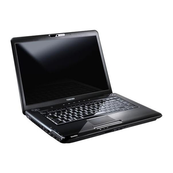
Page 21: Figure 1-1 Front Of The Computer
USB Bluetooth Module standard Ver 2.1 & EDR(Enhanced Data Rate) equipped θ Security Kensington Lock, Fingerprint –Enhanced Lock is also equipped. θ HDD Password θ 3D Accelerometer for HDD Figure 1-1 Front of the computer Satellite A300 Maintenance Manual (960-Q08)
-
Page 22
Chapter 1 Hardware Overview Satellite A300 Maintenance Manual (960-Q08) -
Page 23: System Block Diagram
Chapter 1 Hardware Overview System Block Diagram Figure 1-2 shows the system block diagram. Figure 1-2 System block diagram for Intel Platform Satellite A300 Maintenance Manual (960-Q08)
-
Page 24
4GB(2GB for GL960). • 200-pin SO-DIMM • 1.8V operation θ BIOS ROM (Flash memory) • 8Mbit θ Chipset (Santa Rosa Platform) This gate array has the following elements and functions. Satellite A300 Maintenance Manual (960-Q08) -
Page 25
10/100 LAN controller (Marvell 88E8040T-A0-NNC1C000) • GIGA LAN controller (Marvell 88E8072-B1-NNC1C000) θ Mini Card Wireless LAN card (BTO) 5.4 GHz DSSS/OFDM LAN card is equipped. Conformity with IEEE 802.11b/g, IEEE 802.11 a/g/n and IEEE 802.11a/b/g.. Satellite A300 Maintenance Manual (960-Q08) -
Page 26
The transfer speed of data receiving is 56kbps, of data sending is 33.6kbps and of FAX is 14.4kbps. Actual speed depends on the quality of the line used. Connected to telephone line through RJ11 MOD Satellite A300 Maintenance Manual (960-Q08) -
Page 27: Inch Hard Disk Drive
Height (mm) dimens Depth (mm) 100.2 +/- 0.25 ions Weight (g) 97/98 97/98 101//102 101//102 Parameter Standard value FUJITSU FUJITSU FUJITSU FUJITSU MHY2120BH MHY2160BH MHY2200BH MHY2250BH Width (mm) Outline Height dimensi (mm) Depth (mm) 101(Max) Weight Satellite A300 Maintenance Manual (960-Q08)
-
Page 28
95 (max.) 95 (max.) 102 (max.) 102 (max.) Weight (g) Table 1-2 2.5-inch HDD dimensions Parameter Standard value FUJITSU FUJITSU FUJITSU MHX2250BT MHX2300BT MHZ2400BT Width (mm) Outline Height 12.5 dimensi (mm) Depth 70.0 (mm) 101(Max) Weight Satellite A300 Maintenance Manual (960-Q08) -
Page 29: Table 1-2 2.5-Inch Hdd Specifications
200GB 250GB (formatted) Speed (RPM) 5,400 Data transfer Rate — To/From Media 84.6MB/s Max. — T0/From Host 1.5Gbps (150MB/s) bus transfer rate 1.5Gbps(150MB/s) (MB/s) 12.0ms/14.0ms Average random seek time (read) (ms) Power-on-to-ready 4.0 (typ.) (sec) Satellite A300 Maintenance Manual (960-Q08)
-
Page 30
400GB (formatted) Speed (RPM) 4,200 Data transfer Rate — To/From Media 60.8MB/s Max. — T0/From Host 1.5Gbps (150MB/s) bus transfer rate 1.5Gbps (150MB/s) (MB/s) 12.0ms/14.0ms Average random seek time (read) (ms) Power-on-to-ready 4.0 (typ) (sec) Satellite A300 Maintenance Manual (960-Q08) -
Page 31: Optical Drive
Chapter 1 Hardware Overview 1.4 Optical Drive Satellite A300 Maintenance Manual (960-Q08)
-
Page 32: 2Dvd Super Multi Drive
Table 1-3 DVD Super Multi drive outline dimensions Parameter Standard Value Maker TS-L632P DVR- DVR- L632H KD08TBT KD08TBL Width 122.4 122.4 (mm) Outline Height 12.7 12.7 12.7 12.7 dimension (mm) Depth (mm) Mass 176.2 176.2 Satellite A300 Maintenance Manual (960-Q08)
-
Page 33: Table 1-4 Dvd Super Multi Drive Specifications (1/4)
130 ms Ave.140(CD-ROM Ave.140(CD-ROM CD-ROM Mode1Disc is used) Mode 1 Disc is used) Access time (ms) (Random) 130 ms 130 ms Ave.150 Ave.150 DVD-ROM (DVD-ROM Single (DVD-ROM Single Layer Disc is used) Layer Disc is use Satellite A300 Maintenance Manual (960-Q08)
-
Page 34
Single layer, Single 4.7G DVD+- 4.7G DVD+- R/RW (Read & R/RW (Read & Write) Write) DVD+-R Dual DVD+-R Dual (Read & Write) (Read & Write) DVD-RAM DVD-RAM (Read (Read & Write) &Write)80mm 80mm DVD Satellite A300 Maintenance Manual (960-Q08) -
Page 35: Keyboard
Chapter 1 Hardware Overview 1.5 Keyboard The Satellite A300 keyboard has one kind of placement that is for US/UK style. Figure 1-5 is a view of the keyboard for US/UK style Figure 1-5 Keyboard for US/UK style See Appendix E for details of the keyboard layout.
-
Page 36: Figure 1-6 Auo Lcd Module
Chapter 1 Hardware Overview Color Display The Satellite A300 Panel has two different kinds of model, one is single lamp LCD and the other is dual lamp LCD. 1.6.1 LCD Module with Single lamp Figure 1-6 ~ 1-9 shows a view of the LCD module and Table 1-5-1 lists the specifications.
-
Page 37: Figure 1-7 Cmo Lcd Module
Chapter 1 Hardware Overview Figure 1-7 CMO LCD Module Figure 1-8 LG LCD Module Satellite A300 Maintenance Manual (960-Q08)
-
Page 38: Figure 1-9 Sam Lcd Module(Single)
Chapter 1 Hardware Overview Figure 1-9 SAM LCD Module Table 1-5-1 LCD module specifications (Single) Specifications(WXGA) Item LG LP154WX4- Samsung AUO B154EW08 CMO N154I3-L03 TLC8 LTN154AT07-T01 Number of Dots 1,280x 800 Dot spacing (mm) 0.2588(H)× 0.2588(V) Satellite A300 Maintenance Manual (960-Q08)
-
Page 39: 2Fl Inverter Board
Table 1-5-3 FL inverter board specifications-Single lamp Specifications Foxconn Delta SUMIDA Item T18I095.00 DAC-08N035 TWS-449-308 TBD485NR Voltage (V) 8~20 8~20 7~20 8~20 Input Power (W) 7.5W 7.5W 7.5W 7.5W Voltage (Vrms) Output 612~945 612~945 612~945 612~945 Satellite A300 Maintenance Manual (960-Q08)
-
Page 40: Table 1-5-4 Fl Inverter Board Specifications-Dual Lamp
Table 1-5-4 FL inverter board specifications-Dual lamp Specifications Item Foxconn SUMIDA T18I096.00 TWS-449-309 TBD487NR Voltage (V) 8~20 8~20 8~20 Input Power (W) 7.5W 7.5W 7.5W Voltage (Vrms) 612~945 612~945 612~945 Output Current 2.3±0.4 ~ 6.5±0.3 (f=55KHz)(mArms) Satellite A300 Maintenance Manual (960-Q08)
-
Page 41: Table 1-6 Power Supply Output Rating
Power supply (Yes/No) Name Power OFF Power OFF Voltage [V] No Battery Suspend mode Boot mode +5VPCU +5V_S5 +5VSATA USBPWR1 +5V_TP VCCRTC TH_FAN_POWER 3.1~5 +3VPCU +3V_S5 +3VSUS CCD_POWER VCC_XD +1.8VSUS +1.5V 1.25 +1.25V 1.05 +1.05V 0.55~1.575 VCC_CORE Satellite A300 Maintenance Manual (960-Q08)
-
Page 42: Batteries
17mAh MOLEX-58ZL1 1.8.1 Main Battery The main battery is the primary power supply for the computer when the AC adapter is not connected. In Standby, the main battery maintains the current status of the computer. Satellite A300 Maintenance Manual (960-Q08)
-
Page 43: 2Battery Charging Control
About 3 days Hibernation About 1 month Battery 3 cell Approximately 1.5 days(sleep mode) Pack 6 cell Approximately 3 days(sleep mode) 9 cell Approximately 5 days(sleep mode) Approximately 1 month(shutdown mode,All type of battery pack Satellite A300 Maintenance Manual (960-Q08)
-
Page 44: 3Rtc Battery
Table 1-10 lists the Time required for charges of RTC battery and data preservation time. Table 1-10 Time required for charges of RTC battery Condition Time Power ON (Lights Power LED) About 24 hours Data preservation tome (Full-charged) About a month Satellite A300 Maintenance Manual (960-Q08)
-
Page 45: Ac Adapter
Table 1-11 AC adapter specifications Parameter Specification With Led DELTA/ LITE-ON DELTA/ LITE-ON DELTA/ LITE-ON Power 120W Input voltage AC 100V/240V Input frequency 50Hz/60Hz Input current ≦ 1.5A Output voltage DC 19V Output current 3.95A 4.74A 6.3A Satellite A300 Maintenance Manual (960-Q08)
-
Page 46
Chapter 1 Hardware Overview Features The Satellite A300 (10A) (AMD Platform) features are listed below. θ Microprocessor Microprocessor that is used will be different by the model. It supports processors as follows AMD Athlon X2 1600 TK57 (1.9GHz) AMD Turion64 X2 1600 TL60(2.0GHz) -
Page 47
Supported via a 4-pins S-Video connector θ Keyboard Toshiba Standard keyboard with 86-88 keys (desktop-style), Support Windows keys & Application keys. (Toshiba standard layout) Standard pitch, 2.5mm travel length. Multi-langue support. θ New Dummy card slot The new card slot (dummy card) accommodates one 5mm Type II card. The slot support 16-bit PC cards. -
Page 48
The wireless LAN is equipped on the mini card slot. θ LAN/MODEM Connectors for LAN and Modem are separately mounted. θ 1394 One 1394 port is equipped. θ Multiple Digital Media Card Slot XD/MS/MS pro/SD/MMC are supported θ Bluetooth Satellite A300 Maintenance Manual (960-Q02) -
Page 49
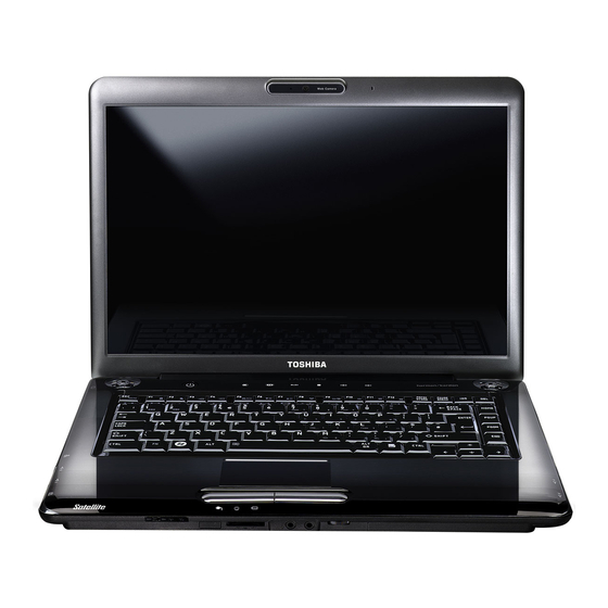
Chapter 1 Hardware Overview USB Bluetooth Module (BTO) V2.1 & EDR(Enhanced Data Rate) equipped θ Security Kensington Lock, Fingerprint –Enhanced Lock is also equipped. HDD Password Figure 1-1 Front of the computer Satellite A300 Maintenance Manual (960-Q02) -
Page 50
Chapter 1 Hardware Overview System Block Diagram Figure 1-2 shows the system block diagram. Figure 1-2 System block diagram for AMD Platform Satellite A300 Maintenance Manual (960-Q02) -
Page 51
• North Bridge (AMD RS690M) − AMD HyperTransport Interface support − PCI Express Interface 1.1a support − A-Link Express II Interface − 465-ball 21 x 21mm FC-BGA Package • South Bridge (AMD SB600) − A-Link Express II Interface (1/2/4-lane) Satellite A300 Maintenance Manual (960-Q02) -
Page 52
The modem supports V.92/V.90 analog receive data up to 56 kbps with V.44 data compression, V.17 analog fax to 14.4 kbps, voice/telephone answering machine (TAM), high quality soft speakerphone. θ Bluetooth USB Bluetooth Module. Bluetooth standard V2.1 +EDR conformity. Satellite A300 Maintenance Manual (960-Q02) -
Page 53
A compact, high-capacity HDD with a height of 9.5mm. Contains a 2.5-inch magnetic disk and magnetic heads. Figure 1-3 shows a view of the 2.5-inch HDD and Tables 1-1 and 1-2 list the specifications. Figure 1-3 2.5-inch HDD Satellite A300 Maintenance Manual (960-Q02) -
Page 54
HTS542520k9SA HTS542525k9S 69.85 +/- 0.25 Width (mm) Outlin Height (mm) dimen 100.2 +/- 0.25 Depth (mm) sions 95 (max.) 95 (max.) 102 (max.) 102 (max.) Weight (g) Table 1-2 2.5-inch HDD dimensions Parameter Standard value Satellite A300 Maintenance Manual (960-Q02) -
Page 55
320GB Speed (RPM) 5,400 Data transfer Rate 794Mbits 730Mbits Media Media — To/From Media 300MBytes Host 3GBytes — T0/From Host Host 1.5Gbps(150MB/s) bus transfer rate (MB/s) Average random seek time (read) (ms) Power-on-to-ready (sec) 3.5(typ)/9.5(Max) Satellite A300 Maintenance Manual (960-Q02) -
Page 56
Speed (RPM) 5,400 Data transfer Rate — To/From Media 65.5MB/s 65.5MB/s 65.5MB/s 65.5MB/s — T0/From Host 1.5Gbps 1.5Gbps 1.5Gbps 1.5Gbps bus transfer rate (MB/s) 150 (MB/s Average random seek time (read) (ms) Power-on-to-ready (sec) 3.5 sec Satellite A300 Maintenance Manual (960-Q02) -
Page 57
400GB (formatted) Speed (RPM) 4,200 Data transfer Rate — To/From Media 60.8MB/s Max. — T0/From Host 1.5Gbps (150MB/s) bus transfer rate 1.5Gbps (150MB/s) (MB/s) 12.0ms/14.0ms Average random seek time (read) (ms) Power-on-to-ready 4.0 (typ) (sec) Satellite A300 Maintenance Manual (960-Q02) -
Page 58
Chapter 1 Hardware Overview 1.4 Optical Drive Satellite A300 Maintenance Manual (960-Q02) -
Page 59
Table 1-3 DVD Super Multi drive outline dimensions Parameter Standard Value Maker TS-L632P DVR- DVR- L632H KD08TBT KD08TBL Width 122.4 122.4 (mm) Outline Height 12.7 12.7 12.7 12.7 dimension (mm) Depth (mm) Mass 176.2 176.2 Satellite A300 Maintenance Manual (960-Q02) -
Page 60
(3X-5X Zone-CLV write) 16.6(PIO 16.6(PIO 33.2MB/s 33.2MB/s Mode4/MultiwordDM ATAPI Mode4/MultiwordDMA A Mode2) interface Mode2) 33.3(UltraDMAMode2 (MB/s) 33.3(UltraDMA Mode2) Access time 130 ms 130 ms Ave.140(CD-ROM Ave.140(CD-ROM CD-ROM Mode1Disc is used) Mode 1 Disc is used) (ms) (Random) Satellite A300 Maintenance Manual (960-Q02) -
Page 61
Single layer, Single 4.7G DVD+- 4.7G DVD+- R/RW (Read & R/RW (Read & Write) Write) DVD+-R Dual DVD+-R Dual (Read & Write) (Read & Write) DVD-RAM DVD-RAM (Read (Read & Write) &Write)80mm 80mm DVD Satellite A300 Maintenance Manual (960-Q02) -
Page 62
Chapter 1 Hardware Overview 1.5 Key board The Satellite A300 keyboard has one kind of placement; one is for US/UK style Figure 1-5 is a view of the keyboard for US style Figure 1-5 Keyboard for US/UK style Satellite A300 Maintenance Manual (960-Q02) -
Page 63
Chapter 1 Hardware Overview Color Display The Satellite A300 Panel has two different kinds of model, one is single lamp LCD and the other is dual lamp LCD. 1.6.1 LCD Module with Single lamp Figure 1-6 ~ 1-9 shows a view of the LCD module and Table 1-5-1 lists the specifications. -
Page 64
Chapter 1 Hardware Overview Figure 1-7 CMO LCD Module Figure 1-8 LG LCD Module Satellite A300 Maintenance Manual (960-Q02) -
Page 65
Chapter 1 Hardware Overview Figure 1-9 SAM LCD Module Table 1-5-1 LCD module specifications (Single) Specifications(WXGA) Item LG LP154WX4- Samsung AUO B154EW08 CMO N154I3-L03 TLC8 LTN154AT07-T01 Number of Dots 1,280x 800 Dot spacing (mm) 0.2588(H)× 0.2588(V) Satellite A300 Maintenance Manual (960-Q02) -
Page 66
Table 1-5-3~1-5-4 lists the FL inverter board specifications. Table 1-5-3 FL inverter board specifications-Single lamp Specifications Foxconn Delta SUMIDA Item T18I095.00 DAC-08N035 TWS-449-308 TBD485NR Voltage (V) 8~20 8~20 7~20 8~20 Input Power (W) 7.5W 7.5W 7.5W 7.5W Satellite A300 Maintenance Manual (960-Q02) -
Page 67
Table 1-5-4 FL inverter board specifications-Dual lamp Specifications Item Foxconn SUMIDA T18I096.00 TWS-449-309 TBD487NR Voltage (V) 8~20 8~20 8~20 Input Power (W) 7.5W 7.5W 7.5W Voltage (Vrms) 612~945 612~945 612~945 Output Current 2.3±0.4 ~ 6.5±0.3 (f=55KHz)(mArms) Satellite A300 Maintenance Manual (960-Q02) -
Page 68
Table 1-6 RS690M Power supply output rating Power supply (Yes/No) Name Power OFF Power OFF Voltage [V] No Battery Suspend mode Boot mode +5VPCU +3VPCU +3V_S5 +3VSUS +2.5V +1.8VSUS +SMDDR_VTERM +SMDDR_VREF +1.8V +1.5V 1.25 +1.2V 1.25 +1.2V_S5 +NB_CORE 1.0~1.2 VCC_CORE 0.7~1.2 Satellite A300 Maintenance Manual (960-Q02) -
Page 69
17mAh MOLEX-58ZL1 1.8.1 Main Battery The main battery is the primary power supply for the computer when the AC adapter is not connected. In Standby, the main battery maintains the current status of the computer. Satellite A300 Maintenance Manual (960-Q02) -
Page 70
About 3 days Hibernation About 1 month Battery 3 cell Approximately 1.5 days(sleep mode) Pack 6 cell Approximately 3 days(sleep mode) 9 cell Approximately 5 days(sleep mode) Approximately 1 month(shutdown mode,All type of battery pack Satellite A300 Maintenance Manual (960-Q02) -
Page 71
Table 1-10 lists the Time required for charges of RTC battery and data preservation time. Table 1-10 Time required for charges of RTC battery Condition Time Power ON (Lights Power LED) About 24 hours Data preservation tome (Full-charged) About a month Satellite A300 Maintenance Manual (960-Q02) -
Page 72
Table 1-11 AC adapter specifications Parameter Specification With Led DELTA/ LITE-ON DELTA/ LITE-ON DELTA/ LITE-ON Power 120W Input voltage AC 100V/240V Input frequency 50Hz/60Hz Input current ≦ 1.5A Output voltage DC 19V Output current 3.95A 4.74A 6.3A Satellite A300 Maintenance Manual (960-Q02) -
Page 73: Troubleshooting Procedures
Chapter 2 Troubleshooting Procedures Satellite A300 Maintenance Manual(960-Q08)
-
Page 74
Satellite A300 Maintenance Manual(960-Q08) -
Page 75
Keyboard Troubleshooting ………………31 Procedure 1 Diagnostic Test Program Execution Check ……31 Procedure 2 Connector Check and Replacement Check……32 Touch pad Troubleshooting ………………33 Procedure 1 Diagnostic Test Program Execution Check ……33 Procedure 2 Connector Check and Replacement Check……34 Satellite A300 Maintenance Manual(960-Q08) -
Page 76: Procedure
Fingerprint Troubleshooting ………………47 Procedure 1 Diagnostic Test Program Execution Check ……47 Procedure 2 Connector Check and Replacement Check……47 2.16 Bluetooth Troubleshooting ………………48 Procedure 1 Diagnostic Test Program Execution Check ……48 Procedure 2 Connector Check and Replacement Check……48 Satellite A300 Maintenance Manual(960-Q08)
-
Page 77: Troubleshooting
1. Phillips screwdrivers (For replacement procedures) 2. Implements for debugging port check • Toshiba MS-DOS system FD • RS-232C cross cable • Test board with debug port test cable • PC for displaying debug port test result Satellite A300 Maintenance Manual (960-Q08)
-
Page 78: Procedure
There are following two types of connections in the figure of board and module connection in and after 2.3 Power Supply Troubleshooting. (1) Cable connection is described in the figure as line. (2) Pin connection is described in the figure as arrow. <e.g.> Connection of modem Satellite A300 Maintenance Manual (960-Q08)
-
Page 79: Troubleshooting Flowchart
Before going through the flowchart steps, verify the following: Ask him or her to enter the password if a password is registered. Verify with the customer that Toshiba Windows is installed on the hard disk. Non- Windows operating systems can cause the computer to malfunction.
-
Page 80
2 Troubleshooting Procedures Figure 2-1 Troubleshooting flowchart (1/2) Satellite A300 Maintenance Manual (960-Q08) -
Page 81
2 Troubleshooting Procedures Figure 2-2 Troubleshooting flowchart (2/2) If the diagnostics program cannot detect an error, the problem may be intermittent. The Test program should be executed several times to isolate the problem. Check the Log Utilities Satellite A300 Maintenance Manual (960-Q08) -
Page 82: System Test
13. If an error is detected on the fingerprint test, perform the fingerprint Troubleshooting Procedures in Section 2.16. 14. If an error is detected on the Bluetooth test, perform the Bluetooth Troubleshooting Procedures in Section 2.17. Satellite A300 Maintenance Manual (960-Q08)
-
Page 83: Power Supply Troubleshooting
The battery level is low while the system power is ON. (even intervals) Blinks orange once The system is driven by only a battery and the battery level (at being switched on) is low. Doesn’t light Any condition other than those above. Satellite A300 Maintenance Manual (960-Q08)
-
Page 84
Check 1 If the DC IN icon blinks orange, go to Procedure 2. Check 2 If the DC IN icon does not light, go to Procedure 3. Check 3 If the battery icon does not light orange, go to Procedure 4. NOTE: Use a supplied AC adapter. Satellite A300 Maintenance Manual (960-Q08) -
Page 85: Procedure 2 Error Code Check
Bad Address Mark Error Record Not Found HDC Not Reset Error Drive Not Initialized DMA Boundary Error Bad Sector Bad Track Error ECC Error ECC Recover Enabled HDC Error Seek Error Time Out Error Drive Not Ready Satellite A300 Maintenance Manual (960-Q08)
-
Page 86
Cache Memory Protect Mode Error Caching Error Other Error Multimedia Write Error Invalid Drive Drive Not Ready Other Error NOTE: If error status name is Other Error , please reference the Error Code for error information Satellite A300 Maintenance Manual (960-Q08) -
Page 87: Procedure 3 Connection Check
If the battery pack is still not charged, go to Check 5. Check 5 Replace the battery pack with a new one. If the battery pack is still not charged, go to Procedure 5. Satellite A300 Maintenance Manual (960-Q08)
-
Page 88: Procedure 5 Replacement Check
(When driving with battery pack) Check 1 Battery pack may be faulty. Replace it with a new one. If the problem still occurs, perform Check 2. Check 2 System board may be faulty. Replace it with a new one. Satellite A300 Maintenance Manual (960-Q08)
-
Page 89: System Board Troubleshooting
Procedure 1 and continue with the other procedures as instructed. The procedures described in this section are: Procedure 1: Message Check Procedure 2: Debugging Port Check Procedure 3: Diagnostic Test Program Execution Check Procedure 4: Replacement Check Satellite A300 Maintenance Manual (960-Q08)
-
Page 90: Procedure 1
The following error message appears when data stored in RAM under the resume function is lost because the battery has become discharged or the system board is damaged. Go to Procedure 3. WARNING: RESUME FAILURE. PRESS ANY KEY TO CONTINUE. Satellite A300 Maintenance Manual (960-Q08)
-
Page 91
(16) PIC #1 ERROR (17) PIC #2 ERROR (18) KBC ERROR (19) HDC ERROR (20) HDD #0 ERROR (21) HDD #1 ERROR (22) NO FDD ERROR (23) FDC ERROR (24) TIMER INTERRUPT ERROR (25) RTC UPDATE ERROR Satellite A300 Maintenance Manual (960-Q08) -
Page 92: Debugging Port Check
Initialize caches to initial POST values Initialize I/O component Initialize the local bus IDE Initialize Power Management Load alternate registers with initial POST values Restore CPU control word during warm boot Initialize PCI Bus Mastering devices Satellite A300 Maintenance Manual (960-Q08)
-
Page 93: Keyboard
Test for unexpected interrupts Initialize POST display service Display prompt «Press F2 to enter SETUP» Disable CPU cache Test RAM between 512 and 640 KB Test extended memory Test extended memory address lines Jump to UserPatch1 Satellite A300 Maintenance Manual (960-Q08)
-
Page 94
Check for SMART Drive (optional) Shadow option ROMs Set up Power Management Initialize security engine (optional) Enable hardware interrupts Determine number of ATA and SCSI drives Set time of day Check key lock Initialize Typematic rate Erase F2 prompt Satellite A300 Maintenance Manual (960-Q08) -
Page 95
Initialize POST Error Manager (PEM) Initialize error logging Initialize error display function Initialize system error handler PnPnd dual CMOS (optional) Initialize notebook docking (optional) Initialize notebook docking late Force check (optional) Extended checksum (optional) Unknown interrupt Satellite A300 Maintenance Manual (960-Q08) -
Page 96
Shadow Boot Block System memory test Initialize interrupt vectors Initialize Run Time Clock Initialize video Initialize System Management Mode 1 Output one beep before boot Boot to Mini DOS Clear Huge Segment Boot to Full DOS Satellite A300 Maintenance Manual (960-Q08) -
Page 97: Dmi Information
If an error is detected during these tests, go to Procedure 4. Procedure 4 Replacement Check System board may be faulty. Disassemble the computer following the steps described in Chapter 4, Replacement Procedures and replace system board with a new one. Satellite A300 Maintenance Manual (960-Q08)
-
Page 98: Usb Fdd Troubleshooting
Procedure 2. Detailed operation is given in Chapter 3, Tests and Diagnostics. If the test program cannot be executed on the computer, go to Procedure 3. Satellite A300 Maintenance Manual (960-Q08)
-
Page 99: Diagnostic Test Program Execution Check
“write enable”. If any other message appears, perform Check 2. Write protected Check 2 Make sure the floppy disk is formatted correctly. If it is, go to Procedure 3. Satellite A300 Maintenance Manual (960-Q08)
-
Page 100: Procedure 3 Connector Check And Replacement Check
NOTE: When checking the connection, be sure to check it with care for the followings. 1. Cable can not be disconnected from the connector. 2. Cable is connected straight to the connector. 3. Cable is connected all the way seated in the connector. 4. Cable can not be broken. Satellite A300 Maintenance Manual (960-Q08)
-
Page 101
If it does not work properly when connected to CN12, CN19, CN20 or all ports, perform Check 4. Check 4 System board may be faulty. Replace it with a new one following the steps in Chapter 4, Replacement Procedures. Satellite A300 Maintenance Manual (960-Q08) -
Page 102: Hdd Troubleshooting
User’s Manual. Procedure 1 Partition Check Insert the Toshiba MS-DOS system disk and start the computer. Perform the following checks: Input C: and press Enter. If you cannot change to drive C, go to Check 2. If you Check 1 can change to drive C, go to Procedure 2.
-
Page 103: Message Check
2.5” HDD(s) and the connector(s) of system board may be defective (Refer to the steps described in Chapter 4, Replacement Procedures for disassembling.). Insert HDD(s) to the connector(s) firmly. If it is (or they are) firmly connected, go to Procedure 3. Satellite A300 Maintenance Manual (960-Q08)
-
Page 104: Format Check
Using the Diagnostic Disk, format 2.5” HDD with a format option (physical format). If HDD is formatted, set the 2.5” HDD partition using MS-DOS FDISK command. If you cannot format 2.5” HDD using the Tests and Diagnostic program, go to Procedure 4. Satellite A300 Maintenance Manual (960-Q08)
-
Page 105: Diagnostic Test Program Execution Check
HDD — ECC RECOVER ENABLE HDD — DRIVE NOT READY HDD — WRITE FAULT HDD — STATUS ERROR HDD — BAD SECTOR HDD — ACCESS TIME ERROR HDD — NO HDD HDD — DMA CRC ERROR Satellite A300 Maintenance Manual (960-Q08)
-
Page 106: Procedure 5 Connector Check And Replacement Check
Chapter 4, Replacement Procedures and check the operation. If the problem still occurs, perform Check 3. Check 3 System board may be faulty. Replace it with a new one following the instructions in Chapter 4, Replacement Procedures. Satellite A300 Maintenance Manual (960-Q08)
-
Page 107: Keyboard Troubleshooting
ONE TEST) in the Diagnostic Program. Refer to Chapter 3, Tests and Diagnostics, for more information on how to perform the test program. If an error occurs, go to Procedure 2. If an error does not occur, keyboard is functioning properly. Satellite A300 Maintenance Manual (960-Q08)
-
Page 108: Procedure 2 Connector Check And Replacement Check
Keyboard may be faulty. Replace it with a new one following the instructions in Chapter 4, Replacement Procedures. If the problem still occurs, perform Check 3. Check 3 System board may be faulty. Replace it with a new one following the instructions in Chapter 4, Replacement Procedures. Satellite A300 Maintenance Manual (960-Q08)
-
Page 109: Touch Pad Troubleshooting
Execute the Touch pad test (ONLY ONE TEST) in the Diagnostic Program. Refer to Chapter 3, Tests and Diagnostics, for more information on how to perform the test program. If an error occurs, go to Procedure 2. If an error does not occur, touch pad is functioning properly. Satellite A300 Maintenance Manual (960-Q08)
-
Page 110: Procedure 2 Connector Check And Replacement Check
Chapter 4, Replacement Procedures. If the problem still occurs, perform Check 3. Check 3 System board may be faulty. Replace it with a new one following the instructions in Chapter 4, Replacement Procedures Satellite A300 Maintenance Manual (960-Q08)
-
Page 111: Display Troubleshooting
Insert the Diagnostics disk in the USB FDD, turn on the computer and run the test. Refer to Chapter 3, Tests and Diagnostics for details. If an error is detected, go to Procedure 3. Satellite A300 Maintenance Manual (960-Q08)
-
Page 112: Connector And Cable Check
HV cable. Their cables may be disconnected from system board or FL inverter board. Disassemble the computer following the steps described in Chapter 4, Replacement Procedures. If the connection is loose, reconnect firmly and restart the computer. If the problem still occurs, go to Procedure 4. Satellite A300 Maintenance Manual (960-Q08)
-
Page 113: Procedure 4 Replacement Check
Chapter 4, Replacement Procedure and test the display again. If the problem still occurs, perform Check 5. Check 5 System board may be faulty. Replace it with a new one following the instructions in Chapter 4, Replacement Procedure. Satellite A300 Maintenance Manual (960-Q08)
-
Page 114: Optical Disk Drive Troubleshooting
Optical disk drive may be faulty. Replace it with a new one following the steps in Chapter 4. If the problem still occurs, perform Check 3. Check 3 System board may be faulty. Replace it with new one following the instructions in Chapter 4. Satellite A300 Maintenance Manual (960-Q08)
-
Page 115: Modem Troubleshooting
Disassemble the computer following the steps described in Chapter 4 and perform the following checks: Check 1 Make sure the following connections are firmly connected. If any connector is disconnected, connect it firmly and return to Procedure 1. If the problem still occurs, perform Check 2. Satellite A300 Maintenance Manual (960-Q08)
-
Page 116
Cable between MDC and system board may be faulty. Replace it with a new one following the instructions in Chapter 4. If the problem still occurs, perform Check Check 6 System board may be faulty. Replace it with a new one following the instruction in Chapter 4. Satellite A300 Maintenance Manual (960-Q08) -
Page 117: Lan Troubleshooting
LAN cable may be faulty. Replace it with a new one. If the problem still occurs, perform Check 3. Check 3 System board may be faulty. Replace it with a new one following the instruction in Chapter 4. Satellite A300 Maintenance Manual (960-Q08)
-
Page 118: Wireless Lan Troubleshooting
LAN. You will need a second computer that can communicate by wireless LAN. Perform the test following the instructions described in Chapter 3. If the computer passes the test, the function is correctly working. If the computer does not pass the test, perform Procedure 2. Satellite A300 Maintenance Manual (960-Q08)
-
Page 119: Antennas’ Connection Check
Make sure that wireless LAN antenna cables (black and white) are firmly connected to the connectors on Wireless LAN card. If wireless LAN antenna cables are not connected properly, connect them firmly and perform Procedure 1. If the problem still occurs, go to the procedure 3. Satellite A300 Maintenance Manual (960-Q08)
-
Page 120: Procedure 3 Replacement Check
Wireless LAN card may be faulty. Replace it with a new one following the instructions in Chapter 4, Replacement Procedures. If the problem still occurs, perform Check 3. Check3 System board may be faulty. Replace it with a new one following the instructions in Chapter 4, Replacement Procedures. Satellite A300 Maintenance Manual (960-Q08)
-
Page 121: Sound Troubleshooting
Connector Check The connection of sound system is shown in the following figure. As the connection may be defective, disassemble the PC and check each connection. If the problem still occurs, go to Procedure 2. Satellite A300 Maintenance Manual (960-Q08)
-
Page 122
Chapter 4. If the problem still occurs, perform Check 6. Check 6 Audio board/System board may be faulty. Replace it with a new one following the instructions in Chapter 4. Satellite A300 Maintenance Manual (960-Q08) -
Page 123: Procedure 1 Diagnostic Test Program Execution Check
Fingerprint may be faulty. Replace it with a new one following the steps in Chapter 4. If the problem still occurs, perform Check 4. Check 4 System board may be faulty. Replace it with a new one following the instruction in Chapter 4. Satellite A300 Maintenance Manual (960-Q08)
-
Page 124: Bluetooth Troubleshooting
Bluetooth may be faulty. Replace it with a new one following the steps in Chapter 4. If the problem still occurs, perform Check 4. Check 4 System board may be faulty. Replace it with a new one following the instruction in Chapter 4. Satellite A300 Maintenance Manual (960-Q08)
-
Page 125: Replacement Procedures
Chapter 4 Replacement Procedures Satellite A300 Maintenance Manual(960-Q08)
-
Page 126
Replacement Procedures Satellite A300 Maintenance Manual(960-Q08) -
Page 127
Optical disk drive………………… 4-23 Display assembly ………………… 4-24 4.10 Cover assembly………………….4-29 4.11 Touch pad……………………. 4-33 4.12 USB board ………………….. 4-34 4.13 System board………………….4-36 4.14 CPU……………………..4-39 4.15 LCD unit / FL inverter ………………… 4-42 4.16 Grease/Thermal pad………………………………………………………………..4-48 Satellite A300 Maintenance Manual(960-Q08) 4-iii… -
Page 128: Audio Board
Figure 4-27 Removing the CPU heat sink …………….4-40 Figure 4-28 Removing the CPU ………………4-40 Figure 4-29 Applying silicon grease………………4-41 Figure 4-30 Removing the display mask …………….4-43 Figure 4-31 Removing the FL inverter …………….4-44 Satellite A300 Maintenance Manual(960-Q08)
-
Page 129
Figure 4-34 Thermal pad North Bridge …………….4-51 Figure 4-35 Apply silicon grease for North Bridge …………. 4-52 Figure 4-36 Thermal pad & VRAM position …………..4-52 Figure 4-37 Thermal pad position………………4-53 Figure 4-38 Thermal pad & VRAM position …………..4-54 Satellite A300 Maintenance Manual(960-Q08) -
Page 130: Overview
The tilt stand, if it is installed, can be removed without any other FRUs removed. • Chart Notation The chart shows the case for the following example: • Removing a MDC All FRUs down to the “4.2 Battery pack” to “4.10 Cover assembly” above a SD board/Microphone/MDC must be removed. Satellite A300 Maintenance Manual(960-Q08)
-
Page 131: Safety Precautions
DANGER: 1. In the case of the battery, always use authentic parts or equivalent parts approved by Toshiba. Other batteries may have different specifications that are incompatible with the computer and may result in fire or explosion.
-
Page 132: Before You Begin
Screw sizes are noted in the text and figures. 9. As all parts have sharp edges and corners, take care not to cut yourself. 10. After replacing an FRU, check that the computer and replaced part operate correctly. Satellite A300 Maintenance Manual(960-Q08)
-
Page 133: Disassembly Procedure
Normal pin connectors are used for all other cables. Simply pull out or push in these connectors to disconnect or reconnect. Pressure plate connector Spring connector Satellite A300 Maintenance Manual(960-Q08) 4-4…
-
Page 134: Assembly Procedure
One Philips screwdriver with type 1 bit (for screws other than above) • Tweezers (for lifting screws) • ESD mats (lay on work table or floor) • An ESD wrist strap and heel grounder • Anti-static carpet or flooring Satellite A300 Maintenance Manual(960-Q08)
-
Page 135: Screw Tightening Torque
Special length screw: Blue G r ip a r e a “Special length screw” means screws whose length is indicated in an integral number to the first decimal places such as 2.5 mm, 2.8 mm and so on. Satellite A300 Maintenance Manual(960-Q08) 4-6…
-
Page 136: Screw Notation
Screw shape + Screw length (mm) Screw shape B: Bind screw F: Thin head screw S: Super thin head screw T: Tapping screw U: Other screws (Unique screws: pan head, stud, etc.) Example: B6 … 6mm bind screw Satellite A300 Maintenance Manual(960-Q08)
-
Page 137: Battery Pack
4. Slide and hold the battery release latch (1) to free the battery pack after moving the battery release lock (2) into it unlock position – pick the battery pack out of the computer from fillister. Latch 1 Fillister Latch 2 Figure 4-1-1 Removing the battery pack Satellite A300 Maintenance Manual(960-Q08) 4-8…
-
Page 138
Dispose always the used battery pack in accordance with the laws and ordinances of your local authority. Use only the batteries approved by Toshiba. NOTE: Check visually the battery terminals and clean off any dirt with a dry cloth. -
Page 139
Replacement Procedures Satellite A300 Maintenance Manual(960-Q08) 4-10… -
Page 140: Dummy New Card
NOTE: If a Dummy card is not inserted all the way, the eject button may not pop out. Be sure to push a Dummy card firmly and press the eject button again. Push Figure 4-2-1 Removing a Dummy card Satellite A300 Maintenance Manual(960-Q08) 4-11…
-
Page 141
The following describes the procedure for inserting a Dummy card (See Figure 4-2-2). 1. Make sure the eject button does not stick out. 2. Insert a Dummy card and press it until it is securely connected. Figure 4-3-2 Insert a Dummy card Satellite A300 Maintenance Manual(960-Q08) 4-12… -
Page 142: Hdd
2. Remove the following screws securing a HDD slot cover and remove a HDD slot cover. • M2.5×3.0B FLAT BIND screw 3. Remove the following screws securing the HDD assembly. • M2.5×3.0B FLAT BIND screw 4. Disconnect the HDD assembly from the connector on the system board. Satellite A300 Maintenance Manual(960-Q08) 4-13…
-
Page 143
Replacement Procedures CAUTION: When a HDD is installed, they are installed in the position as the following figure. Figure 4-4 Removing the HDD assembly Satellite A300 Maintenance Manual(960-Q08) 4-14… -
Page 144
Replacement Procedures 5. Remove the following screws securing the HDD holder and remove the HDD holder. • M3.0×3.5B FLAT BIND screw Figure 4-4 Removing a HDD Satellite A300 Maintenance Manual(960-Q08) 4-15… -
Page 145
HDD holder. 2. Insert the HDD assembly into the HDD slot and connect it carefully on the system board. 3. Secure the HDD assembly with the following screw. • M2.5×3.0B FLAT BIND screw Satellite A300 Maintenance Manual(960-Q08) 4-16… -
Page 146: Wireless Lan Card
• Remove the screw: 2.0 x 3.0 2. Open the left and right latches holding a wireless LAN card and remove a wireless LAN card from the connector on the system board. Figure 4-5 Removing a wireless LAN card Satellite A300 Maintenance Manual(960-Q08) 4-17…
-
Page 147
LAN card and lock the secure screws. 2. Connect the wireless LAN antenna cables to the terminals on a wireless LAN card. 3. Install the wireless LAN card cover and secure it with the following screw. Satellite A300 Maintenance Manual(960-Q08) 4-18… -
Page 148: Memory Module
(See Figure 4-6). 1. Loose the screw securing the memory slot cover. 2. Remove the memory slot cover. 3. Open the left and right latches and remove a memory module. Figure 4-6 Removing a memory module Satellite A300 Maintenance Manual(960-Q08) 4-19…
-
Page 149
3. When the power of the computer is turned on, the computer checks automatically the memory size. Confirm that the new memory is detected correctly. 4. If the memory is not detected, check that it is connected correctly. Socket1 Socket2 Figure 4-7 Insert a memory module Satellite A300 Maintenance Manual(960-Q08) 4-20… -
Page 150: Keyboard
3. Upside down the computer. 4. Remove KBD holder. Remove the KB holder screw: M2.5 x 3B 5. Insert your finger into the keyboard slot and keyboard. Then lift up the keyboard to remove it. 6. Disconnect keyboard cable. Satellite A300 Maintenance Manual(960-Q08) 4-21…
-
Page 151
Replacement Procedures Figure 4-8 Removing screws for KB Holder Figure 4-9 Removing the keyboard/KB Holder Satellite A300 Maintenance Manual(960-Q08) 4-22… -
Page 152
2. Slide and set the speaker cover assembly and secure it with the following screw. • M2.5×3.0B FLAT BIND screw • M2.0x 1.8B FLAT BIND screw 3. Install the keyboard brace by pressing it from the topside. Satellite A300 Maintenance Manual(960-Q08) 4-23… -
Page 153: Optical Disk Drive
1. Remove Keyboard and next remove the following screws securing an optical disk drive. • M2.5×1.0B FLAT BIND screw 2. Disconnect an optical disk drive toward the arrow direction from the connector on the system board. M2.0×3.0B FLAT BIND screw Figure 4-11 Removing an optical disk drive Satellite A300 Maintenance Manual(960-Q08) 4-24…
-
Page 154
• M2.0×3.0 Flat BIND screw 2. Insert an optical disk drive assembly into the slot and connect it to the connector on the system board. 3. Secure the ODD drive with the following screw. M2.5×3.0B Flat BIND screw Satellite A300 Maintenance Manual(960-Q08) 4-25… -
Page 155: Display Assembly
2. Open the MINIPCI Door and remove the wireless LAN screws and antenna connector. M2.0x3.0 FLAT BIND (Locktight) Figure 4-13 Removing the screws (securing display assembly) 3. Open the display and removing the k/b holder and keyboard. (please refer figure 4- 8,figure4-9). 4. Disassembly TOP ASSY 4-24 Satellite A300 Maintenance Manual(960-Q08)
-
Page 156
Replacement Procedures Figure 4-14 Removing the screws (from bottom side) Figure 4-15 Removing the screws (from top side) 4-25 Satellite A300 Maintenance Manual(960-Q08) -
Page 157
Figure 4-16 Removing the Wireless Antenna and LCD cable 6. Opening the display to 180 degree, and remove the hinge screw. ‧ M2.5×5.0 FLAT BIND screw (Locktight) Wireless LAN antenna cable Figure 4-17 Removing the hinge screw 4-26 Satellite A300 Maintenance Manual(960-Q08) -
Page 158
5. Pulling out the pole of hinge from the hole of hinge assembly, remove the display assembly from the base assembly. Display assembly Base assembly Figure 4-18 Removing the LCD harness and remove display assembly 4-27 Satellite A300 Maintenance Manual(960-Q08) -
Page 159
5. Pass the cables to the back of computer through the slot. 6. Arrange the wireless LAN antenna along the guide and contact with the connector. 7. Install the LAN board and cover ASSY of the system. 4-28 Satellite A300 Maintenance Manual(960-Q08) -
Page 160: Cover Assembly
• M2.0×8.0 FLAT BIND screw Back • M2.5×4.5 FLAT BIND screw Back Figure 4-19 removing the screws (back) 3. Disconnect the touch pad flat cable/Fingerprint cable/Bluetooth Cable from the connector on the system board. 4-29 Satellite A300 Maintenance Manual(960-Q08)
-
Page 161
Replacement Procedures Figure 4-20 Disconnect the touch pad flat cable/Fingerprint cable/Bluetooth Cable 4-30 Satellite A300 Maintenance Manual(960-Q08) -
Page 162
4. Remove the following screws securing the cover assembly from the front of computer. Pull up and remove the cover assembly from the base assembly. M2.0×5.0 FLAT BIND screw Front Figure 4-21 Removing the screws (front) and cover assy 4-31 Satellite A300 Maintenance Manual(960-Q08) -
Page 163
3. Secure the cover assembly with the following screws from the back and bottom of computer. • M2.0×8.0 FLAT BIND screw Back • M2.5×6.5 FLAT BIND screw Back 4. Disassemble the cable from cable-drain while taking the antenna cable to PCB hole. 4-32 Satellite A300 Maintenance Manual(960-Q08) -
Page 164: Touch Pad
2. Remove the following screws securing the touch pad plate. • M2.5×3.0B SUPER THIN HEAD screw 3. Remove the touch pad board and touch pad plate. 4. Peel off and remove the touch pad from the cover assembly. 4-33 Satellite A300 Maintenance Manual(960-Q08)
-
Page 165
SUPER THIN HEAD screw 4. Stick the insulator on the touch pad plate. 5. Connect the touch pad flat cable to the connector on the touch pad and stick the glass tape on the connector. 4-34 Satellite A300 Maintenance Manual(960-Q08) -
Page 166: Usb Board
Installing the USB board 1. Insert the USB board into base case 2. Fix the below screws M2.5×6.5 FLAT BIND screw NOTE: Be careful not to catch the cables between cover assembly and base assembly. 4-35 Satellite A300 Maintenance Manual(960-Q08)
-
Page 167: System Board
1. Disconnect the power from the system board (See Figure 4-25) Figure 4-25 Disconnect the cable 2. Disconnect the speaker cable, USB cable from the connector on the system board. 3. Remove the following screws securing the system board and remove the system Satellite A300 Maintenance Manual(960-Q08)
-
Page 168
Replacement Procedures board. (See Figure 4-26) • M2.5×6.5 BIND screw Figure 4-26 Removing the system board Satellite A300 Maintenance Manual(960-Q08) -
Page 169
1. Secure the system board with the following screws. • M2.5×6.5 BIND screw 2. Connect the speaker cable, USB cable to the connector on the system board. 3. Connect the power cable to the connector on the system board Satellite A300 Maintenance Manual(960-Q08) -
Page 170: Cpu
NOTE: When removing the heat sink holder, be sure to remove the screws in the reverse order of the number marked on the holder. 3. Remove the CPU heat sink. Figure 4-27 Removing the CPU heat sink Satellite A300 Maintenance Manual(960-Q08)
-
Page 171
5. Please apply 0.1cc silicon grease (Shinetsu 7762) or A000018440 (XY0GFCM1000) GFC-M1 for each repair NOTE: Apply the silicon grease enough to cover the chip surface using the special applicator. Thermal pad is fixed for each one, no need special applicator. Satellite A300 Maintenance Manual(960-Q08) -
Page 172
7. Connect the Heat sink cable to the connector on the system board NOTE: When securing the heat sink holder, be sure to secure the screws in the order of the number marked on the holder. Satellite A300 Maintenance Manual(960-Q08) -
Page 173
1. Remove the following screws securing the display mask M2.5×5.0 BIND screw X6 2. Insert your finger between the edge of the display mask and the LCD, and remove the display mask while releasing the latches of display mask. Satellite A300 Maintenance Manual(960-Q08) -
Page 174
Replacement Procedures Satellite A300 Maintenance Manual(960-Q08) -
Page 175
Replacement Procedures Satellite A300 Maintenance Manual(960-Q08) -
Page 176
Replacement Procedures Satellite A300 Maintenance Manual(960-Q08) -
Page 177
4. Disconnect the LCD harnesses from the connectors CN1 on the FL inverter. 5. Disconnect the HV harnesses from the connectors CN2 on the FL inverter. 6. Remove the FL inverter while peeling off the double-sided tape. Satellite A300 Maintenance Manual(960-Q08) -
Page 178: Lcd Unit / Fl Inverter
Replacement Procedures Insulator LCD harness FL inverter Double-sided tape HV harness Figure 4-31 Removing the FL inverter Satellite A300 Maintenance Manual(960-Q08)
-
Page 179
8. With the bottom edge of the LCD unit on the display cover, lift only the top edge of the LCD unit. After peeling off the CONDUTIVE tape, disconnect the LCD harness from the connector on the back of the LCD. 9. Remove the LCD unit. Figure 4-32 Removing the LCD unit Satellite A300 Maintenance Manual(960-Q08) -
Page 180
Replacement Procedures 10. Remove the following screws securing the LCD support (LCD unit side) and remove the LCD supports from the LCD unit. • M2.0x2.5 BINK screw Figure 4-33 Removing the LCD supports Satellite A300 Maintenance Manual(960-Q08) -
Page 181
8. Secure the display mask with following screws M2.5×5.0 BIND screw x6 9. Cover screws with Screw rubber cover x6 NOTE: When installing the display mask, make sure there is no gap between the display mask and the display cover. Satellite A300 Maintenance Manual(960-Q08) -
Page 182
Replacement Procedures Application for Grease (Denka FCR-AS)/Thermal pad on North 4.16 Bridge, VGA,V-RAM I. For Satellite A300, Satellite Pro A300, EQUIUM A300, SATEGO A300(INT without VGA board) use Thermal pad on North Bridge TSB PN RW PN Used on A000032180 JXBL5016010 N-BRIDGE THERMAL PAD BL5(JXBL5016,3A) -
Page 183
A000032230 JXBL5021010 VRAM4 THERMAL PAD BL5(JXBL5021,REV3A) Figure 4-36 Thermal pad & VRAM position III. For Satellite A300D, Satellite Pro A300D, EQUIUM A300D, SATEGO A300D (AMD without VGA board) use the thermal pad only on North Bridge. Satellite A300 Maintenance Manual(960-Q08) -
Page 184
DIS NB PAD FSL-BS BD3A(JXBD3028,3A) JXBD3029010 A000037560 DIS VGA PAD 50H BD3A(JXBD3029,3A) JXBD3030010 A000037570 DIS VRAM PAD1 T-FLEX340BD3A(JXBD3030,3A) JXBD3031010 A000037580 DIS VRAM PAD2 T-FLEX340BD3A(JXBD3031,3A) JXBD3032010 A000037590 DIS VRAM PAD3 T-FLEX340BD3A(JXBD3032,3A) JXBD3033010 A000037600 DIS VRAM PAD4 T-FLEX340BD3A(JXBD3033,3A) Satellite A300 Maintenance Manual(960-Q08) -
Page 185
Figure 4-38 Thermal pad & VRAM position NOTE: When applying for grease on North Bridge, one syringe*1cc can cover about six repairs. Thermal pad is fixed for each one, no need special applicator and can re-use. Satellite A300 Maintenance Manual(960-Q08) -
Page 186
Appendices Satellite A300 Maintenance Manual (960-Q08) -
Page 187
Satellite A300 Maintenance Manual (960-Q08) -
Page 188: Fingerprint Board
C.11 CN11 AUDIO BOARD USB Connector…………7 C.12 CN12 BUTTON BOARD Connector ………….. 7 C.13 CN13 Finger Print Board Connector …………… 8 C.14 CN14 PCMCIA Connector …………….8 C.15 CN15 New Card Connector …………….10 Satellite A300 Maintenance Manual (960-Q08)
-
Page 189: Usb Board
Appendix E Keyboard Layout ………………E-1 United States (US) Keyboard……………..E-1 United Kingdom (UK) Keyboard …………..E-1 Arabia (AR) Keyboard ……………..E-2 Belgium (BB) Keyboard…………….E-2 Czech (CZ) Keyboard………………E-3 German (GR) Keyboard …………….E-3 Danish (DK) Keyboard………………E-4 Spanish (SP) Keyboard………………E-4 French (FR) Keyboard……………..E-5 Satellite A300 Maintenance Manual (960-Q08)
-
Page 190
E 19 Japanese (JP) Keyboard…………….E-10 E 20 Swiss (SW) Keyboard ………………E-10 E 21 Hebrew Keyboard………………E-11 E 22 Greek Keyboard………………..E-11 E 23 Slovak (SK) Keyboard………………E-12 E24 TaiWan (TW) Keyboard………………E-12 E 25 Thailand (TH) Keyboard……………..E-13 E 26 Yugosla (YS) Keyboard………………E-13 Satellite A300 Maintenance Manual (960-Q08) -
Page 191
Appendix F Wiring Diagrams………………F-1 RGB Monitor ID Wraparound Connector ………… F-1 LAN Loopbak Connector …………….F-1 Appendix G BIOS Rewrite Procedures …………….G-1 Appendix H EC/KBC Rewrite Procedures …………..H-1 Appendix I Reliability…………………..I-1 Satellite A300 Maintenance Manual (960-Q08) -
Page 192: Appendix A Handling The Lcd Module
LCD cover before securing the module with screws. Do not force the module into place, because stress can affect its performance. Also, the panel’s polarized surface is easily scarred, so be careful when handling it. Satellite A300 Maintenance Manual (960-Q08)
-
Page 193
Do not apply cleanser directly to the panel. 4. If water or other liquid is left on the panel’s surface for a long period, it can change the screen’s tint or stain it. Be sure to quickly wipe off any liquid. Satellite A300 Maintenance Manual (960-Q08) -
Page 194
5. Glass is used in the panel, so be careful not to drop it or let it strike a hard object, which could cause breakage or cracks. 6. CMOS-LSI circuits are used in the module, so guard against damage from electrostatic discharge. Be sure to wear a wrist or ankle ground when handling the module. Satellite A300 Maintenance Manual (960-Q08) -
Page 195
8. Do not store the module at temperatures below specifications. Cold can cause the liquid crystals to freeze, lose their elasticity or otherwise suffer damage. 9. Do not disassemble the LCD module. Disassembly can cause malfunctions. Satellite A300 Maintenance Manual (960-Q08) -
Page 196
Handling the LCD Module 10. If you transport the module, do not use packing material that contains epoxy resin (amine) or silicon glue (alcohol or oxide). These materials can release gas that can damage the panel’s polarization. Satellite A300 Maintenance Manual (960-Q08) -
Page 197
Handling the LCD Module Satellite A300 Maintenance Manual (960-Q08) -
Page 198: System Board
Appendix B Appendix B Board Layout B.1 System Board Figure B-1 System board layout (front) Satellite A300 Maintenance Manual (960-Q08)
-
Page 199
Board Layout Figure B-2 System board layout (Back) Satellite A300 Maintenance Manual(960-Q08) -
Page 200
New Card Connector (13) CN13 Blue Tooth Connector (14) Clock generator (15) Card Reader /1394 (16) CN16 CRT Connector (17) CN23 HDMI Connector (18) CN18 Battery Connector (19) LAN_Marvell_8040/8055 (20) South Bridge (21) CN21 DDR2 Connector Satellite A300 Maintenance Manual(960-Q08) -
Page 201
Board Layout (22) CN22 DDR2 Connector (23) North Bridge (24) CN24 ODD Connector (25) CN25 VGA Connector (26) CN26 LAN Connector (27) (28) CN31 SATA HDD Connector (29) CN32 USB Connector (30) CN33 Mini Card Connector Satellite A300 Maintenance Manual(960-Q08) -
Page 202
<Front layout> Figure B-2-1 Touch Pad board layout (Front) Table B-2-1 Touch Pad board connectors Location Function (01) Mouse Button Left key (02) Mouse Button Left key (03) Mouse Button Right key (04) Mouse Button Right key Satellite A300 Maintenance Manual(960-Q08) -
Page 203
Board Layout <Back layout> Figure B-2-2 Touch Pad board layout (Back) Table B-2-2 Touch Pad board connectors Location Function (01) TP Board to M/B I C signal connector (02) TP Board toM/B LED Connector Satellite A300 Maintenance Manual(960-Q08) -
Page 204
Board Layout B.3 Finger Print Board <Front layout> Figure B-3-1 Finger Print Board layout (Front) Table B-3-1 Finger Print Board connectors Location Function (01) Finger Printer IC <Back layout> Figure B-3-2 Finger Print Board layout (Back) Satellite A300 Maintenance Manual(960-Q08) -
Page 205
Board Layout Table B-3-2 Finger Print Board connectors Location Function (01) Finger Print Board to TP Board connector (02) Finger Print Board to TP Board connector Satellite A300 Maintenance Manual(960-Q08) -
Page 206
PIN No. Signal name INVCCO LCDVCC INVCCO LCDVCC INVCCO LCD-EDIDDATA LCD_EDIDCLK CCD _POWER LVDS_VADG MIC_GND MIC_DATA USBP2+_C DISPON USBP2-_C TXLCLKOUT+ TXUCLKOUT+ TXLCLKOUT- TXUCLKOUT- TXLOUT0+ TXUOUT0+ TXLOUT0- TXUOUT0- TXLOUT1+ TXUOUT1+ TXLOUT1- TXUOUT1- TXLOUT2+ TXUOUT2+ TXLOUT2- TXUOUT2- Satellite A300 Maintenance Manual (960-Q08) -
Page 207
MIC_GND MIC_DATA_LCD CN3 Button Board Connector PIN No. Signal name PIN No. Signal name +3VPCU +5VPCU KEY_INT 3ND_MBDATA 3ND_MBCLK CN4 Keyboard Side Connectors PIN No. Signal name PIN No. Signal name +3VPCU LOW_DET FN0# FN1# Satellite A300 Maintenance Manual (960-Q08) -
Page 208
CN5 Power Board Connectors PIN No. Signal name PIN No. Signal name +5VPCU NBSWON# PWRLED# CN6 CN7 Keyboard Connectors PIN No. Signal name PIN No. Signal name K_LED_P MY16 MX17 K_LED_P MY14 MY7_K MY3_K MY10 MY11 MY12 MY15 Satellite A300 Maintenance Manual (960-Q08) -
Page 209
PIN No. Signal name +5V TP +5VPCU TPDATA_1 TPCLK_1 TP LED ON C BATLED1# BATLED0# PWRLED# SUSLED-EC# SATA LED# ACIN TP-XD-LED CN9 Felica Connectors PIN No. Signal name PIN No. Signal name USBP5+ USBP5- WCS_CLK Satellite A300 Maintenance Manual (960-Q08) -
Page 210
FINGER_POWER — USBP4- USBP4+ CN11 USB Board Connectors PIN No. Signal name PIN No. Signal name +5VPCU USBOC#1 USBP1+ USBP1- USBP0+ USBP0- USB-EN#1 +5PCU CN12 New Card Connectors PIN No. Signal name PIN No. Signal name Satellite A300 Maintenance Manual (960-Q08) -
Page 211
NEW SMCLK NEW SMDATA +NEW_1.5V +NEW_1.5V PCIE_WAKE# +NEW_3VAUX PERST# +NEW_3V +NEW_3V NEW_CLKREQ#_RR CPPE#_ CLK_PCIE_NEW# CLK_PCIE_NEW PCIE_RXP4 PCIE_RXP4 PCIE_TXN4 PCIE_TXN4 CN13Blue Tooth Connectors PIN No. Signal name PIN No. Signal name USBP5+ USBP5- WCS_CLK BT_RESET WCS_DAT USB_DETACH Satellite A300 Maintenance Manual (960-Q08) -
Page 212
CN15 INT SPEAKER Connectors PIN No. Signal name PIN No. Signal name INSPKL-N INSPKL+N INSPKL-N INSPKL+N CN16 CRT Connectors PIN No. Signal name PIN No. Signal name CRT_R1 CRT_G1 CRT_B1 5V_CRT2 CRT_SENSE# CRTDDAT CRTHSYNC CRTVSYNC CRTDCLK Satellite A300 Maintenance Manual (960-Q08) -
Page 213
FANSIG CN18 Battery Connectors PIN No. Signal name PIN No. Signal name MBAT+ MBAT+ TEMP_MBAT MBDATA MBCLK CN19 MINI PCI-E Card WLAN Connectors PIN No. Signal name PIN No. Signal name WLAN_WAKE# WCS_DATR WCS_CLKR +1.5V Satellite A300 Maintenance Manual (960-Q08) -
Page 214
Pin Assignment LAD0_PCIE LAD1_PCIE CLK_PCIEI_MINI#_ LAD2_PCIE CLK_PCIEI_MINI LAD3_PCIE LFRAME#_PCIE RF_EN_WLAN PLTRST# PCIE_RXN1 +3V_S5 PCIE_RXP1 +1.5V WL_SMCLK PCIE_TXN1 WL_SMDATA PCIE_TXP1 USBP3-_B USBP3+_B LED_WLAN# CL_CLK1_MIN LED_WPAN# CL DATA1 MIN +1.5V CL_RST#1_MIN SERIRQ_WLAN Satellite A300 Maintenance Manual (960-Q08) -
Page 215
PIN No. Signal name TV-LUMA TV-CHROMA CN21 DDR2 Connectors PIN No. Signal name PIN No. Signal name SMDDR_VREF_DIMM M_B_DQ4 M_B_DQ5 M_B_DQ0 M_B_DQ6 M_B_DM0 M_B_DQS#0 M_B_DQS0 M_B_DQ7 M_B_DQ1 M_B_DQ3 M_B_DQ2 M_B_DQ13 M_B_DQ12 M_B_DQ9 M_B_DQ8 M_B_DM1 M_B_DQS#1 M_CLK_DDR0 Satellite A300 Maintenance Manual (960-Q08) -
Page 216
Pin Assignment M_B_DQS1 M_CLK_DDR#0 M_A_DQ14 M_A_DQ10 M_A_DQ11 M_A_DQ15 M_A_DQ16 M_A_DQ20 M_A_DQ21 M_A_DQ17 M_A_DQS#2 PM_EXTTS#0 M_A_DQS2 M_B_DM2 M_A_DQ23 M_A_DQ18 M_A_DQ19 M_A_DQ22 M_A_DQ28 M_A_DQ29 M_A_DQ25 M_A_DQ24 M_A_DM3 M_A_DQS#3 M_A_DQS3 M_A_DQ26 M_A_DQ30 M_A_DQ27 M_A_DQ31 Satellite A300 Maintenance Manual (960-Q08) -
Page 217
M_A_A12 M_A_A11 M_A_A9 M_A_A7 M_A_A8 M_A_A6 +1.8VSUS +1.8VSUS M_A_A5 M_A_A4 M_A_A3 M_A_A2 M_A_A1 M_A_A0 +1.8VSUS +1.8VSUS M_A_A10 M_A_BS1 M_A_BS#0 M_A_RAS# M_A_WE# M_CS#0 +1.8VSUS +1.8VSUS M_A_CAS# M_ODT0 M_CS#1 M_A_A13 +1.8VSUS +1.8VSUS M_ODT1 M_A_DQ36 M_A_DQ32 M_A_DQ33 M_A_DQ37 Satellite A300 Maintenance Manual (960-Q08) -
Page 218
Pin Assignment M_A_DQS#4 M_A_DM4 M_A_DQS4 M_A_DQ35 M_A_DQ39 M_A_DQ38 M_A_DQ34 M_A_DQ44 M_A_DQ40 M_A_DQ45 M_A_DQ41 M_A_DQS#5 M_A_DM5 M_A_DQS5 M_A_DQ46 M_A_DQ43 M_A_DQ42 M_A_DQ47 M_A_DQ48 M_A_DQ49 M_A_DQ53 M_A_DQ52 M_CLK_DDR1 M_CLK_DDR#1 M_A_DQS#6 M_A_DQS6 M_A_DM6 M_A_DQ50 M_A_DQ55 Satellite A300 Maintenance Manual (960-Q08) -
Page 219
Pin Assignment M_A_DQ51 M_A_DQ54 M_A_DQ56 M_A_DQ61 M_A_DQ60 M_A_DQ57 M_A_DM7 M_A_DQS#7 M_A_DQS7 M_A_DQ62 M_A_DQ63 M_A_DQ58 M_A_DQ59 GGDAT_SMB GGCLK_SMB CN22 DDR2 Connectors Signal name Signal name SMDDR_VREF_DIMM M_B_DQ0 M_B_DQ5 M_B_DQ1 M_B_DQ4 M_B_DM0 M_B_DQS#0 M_B_DQS0 M_B_DQ7 Satellite A300 Maintenance Manual (960-Q08) -
Page 220
Pin Assignment M_B_DQ6 M_B_DQ2 M_B_DQ3 M_B_DQ12 M_B_DQ13 M_B_DQ8 M_B_DQ9 M_B_DM1 M_B_DQS#1 M_CLK_DDR3 M_B_DQS1 M_CLK_DDR#3 M_B_DQ14 M_B_DQ11 M_B_DQ15 M_B_DQ10 M_B_DQ20 M_B_DQ21 M_B_DQ17 M_B_DQ16 M_B_DQS#2 PM_EXTTS#1 M_B_DQS2 M_B_DM2 M_B_DQ23 M_B_DQ18 M_B_DQ22 M_B_DQ19 M_B_DQ28 M_B_DQ24 M_B_DQ25 M_B_DQ29 Satellite A300 Maintenance Manual (960-Q08) -
Page 221
M_B_DQ27 M_CKE3 M_CKE4 +1.8VSUS +1.8VSUS M_B_BS#2 M_B_A14 +1.8VSUS +1.8VSUS M_B_A12 M_B_A11 M_B_A9 M_B_A7 M_B_A8 M_B_A6 +1.8VSUS +1.8VSUS M_B_A5 M_B_A4 M_B_A3 M_B_A2 M_B_A1 M_B_A0 +1.8VSUS +1.8VSUS M_B_A10 M_B_BS#1 M_B_BS#0 M_B_RAS# M_B_WE# M_CS#2 +1.8VSUS +1.8VSUS M_B_CAS# M_ODT2 Satellite A300 Maintenance Manual (960-Q08) -
Page 222
Pin Assignment M_CS#3 M_B_A13 +1.8VSUS +1.8VSUS M_ODT3 M_B_DQ32 M_B_DQ37 M_B_DQ36 M_B_DQ38 M_B_DQS#4 M_B_DM4 M_B_DQS4 M_B_DQ39 M_B_DQ35 M_B_DQ33 M_B_DQ34 M_B_DQ44 M_B_DQ41 M_B_DQ45 M_B_DQ40 M_B_DQS#5 M_B_DM5 M_B_DQS5 M_B_DQ43 M_B_DQ42 M_B_DQ46 M_B_DQ47 M_B_DQ52 M_B_DQ53 M_B_DQ49 M_B_DQ48 M_CLK_DDR4 Satellite A300 Maintenance Manual (960-Q08) -
Page 223
M_B_DM6 M_B_DQ55 M_B_DQ51 M_B_DQ50 M_B_DQ54 M_B_DQ56 M_B_DQ60 M_B_DQ57 M_B_DQ61 M_B_DM7 M_B_DQS#7 M_B_DQS7 M_B_DQ59 M_B_DQ63 M_B_DQ62 M_B_DQ59 DDRDAT_SMB DDRCLK_SMB CN23 HDMI Connectors PIN No. Signal name PIN No. Signal name HDMITX2P_ C HDMITX2N_ C HDMITX1P_ C Satellite A300 Maintenance Manual (960-Q08) -
Page 224
HDMI HP CN24 ODD Connectors CONN DIP HOUSING 50P 2R FR(P0.8,H6.3) PIN No. Signal PIN No. Signal name name IDERST PDD8 PDD7 PDD9 PDD6 PDD10 PDD5 PDD11 PDD4 PDD12 PDD3 PDD13 PDD2 PDD14 PDD1 PDD15 Satellite A300 Maintenance Manual (960-Q08) -
Page 225
Pin Assignment PDD0 PDDREQ PDIOR# PDIOW# PIORDY PDDACK# IRQ14 PDA1 DIAG# PDA0 PDA2 PDCS1# PDCS3# ODDLED# CN25 VGA Connectors Signal name Signal name PEG RXN15 PEG RN15 PEG RXP15 PEG TXP15 PEG RXN14 PEG TXN14 Satellite A300 Maintenance Manual (960-Q08) -
Page 226
PEG RXP10 PEG TXP10 PEG RXN9 PEG TXN9 PEG RXP9 PEG TXP9 PEG RXN8 PEG TXN8 PEG RXP8 PEG TXP8 PEG RXN7 PEG TXN7 PEG RXP7 PEG TXP7 PEG RXN6 PEG TXN6 PEG RXP6 PEG TXP6 Satellite A300 Maintenance Manual (960-Q08) -
Page 227
PEG RXN1 PEG TXN1 PEG RXP1 PEG TXP1 PEG RXN0 PEG TXN0 PEG RXP0 PEG TXP0 CLK MXM# EV CRT DDCCLK CLK MXM# EV CRT DDCDAT GFXRST# EV HDMI DDCCLK SYSFANON# EV HDMI DDCDAT GFXON Satellite A300 Maintenance Manual (960-Q08) -
Page 228
EV LVDS LTX1 EV LVDS UTX1 EV LVDS LTX#0 EV LVDS UTX#0 EV LVDS LTX0 EV LVDS UTX0 EV LVDS LCLK# EV LVDS UCLK# EV LVDS LCLK EV LVDS UCLK EV TV C/R EV TV Y/G Satellite A300 Maintenance Manual (960-Q08) -
Page 229
Pin Assignment EV TV COMP EV HDMICLK- EV HDMICLK+ EV HDMITX2N EV HDMITX2P EV HDMITX1N EV HDMITX1P EV HDMITX0N EV HDMITX0P VIN VGA VIN VGA Satellite A300 Maintenance Manual (960-Q08) -
Page 230
LAN _ ACTLED# CN28 USB Board Connectors PIN No. Signal name PIN No. Signal name USBPWR0 BUSBP7_ BUSBP7+ CN29 2’nd SATA HDD Connectors PIN No. Signal name PIN No. Signal name SATA_TXP0 SATA_TXN0 SATA_RXN0 SATA_RXP0 Satellite A300 Maintenance Manual (960-Q08) -
Page 231
Pin Assignment +3.3VSATA +3.3VSATA +3.3VSATA CN30 5 in 1 Card Reader Connectors Signal name Signal name XD_CD#C XD_R/B#_C XD_RE#_C XD_CE#C CD_CLE_C XD_ALE_C XD_WE# _C SD_D2_C XD_WPO# _C SD_D3_C VCC_XD SD/MS_CLK_C SD_CMD_C MS_D3/XD_D0_C MS_CD#_C Satellite A300 Maintenance Manual (960-Q08) -
Page 232
MS_D0/ XD_D2_C MS_D3/XD_D0_C MS_D1/XD_D7_C SD_ MS_CLK_C MS_BS/XD_D3_C MS_D2/XD_D1_C SD_D0_C MS_D0/XD_D2_C SD_D1_C MS_BS/XD_D3_C XD_D4_C XD_D5_C XD_D6_C MS_D1/XD_D7_C VCC_XD SD_CD#C SM_WPI#/SD_WP_ CN31 SATA HDD Connectors PIN No. Signal name PIN No. Signal name SATA_TXP1 SATA_TXN1 SATA_RXN1 SATA_RXP1 Satellite A300 Maintenance Manual (960-Q08) -
Page 233
Pin Assignment +3.3VSATA +3.3VSATA +3.3VSATA CN32 USB Board Connectors PIN No. Signal name PIN No. Signal name USBPWR0 BUSBP9_ BUSBP9+ CN33 Mini Card Connectors Signal name Signal name WAKE# BT_DATA Satellite A300 Maintenance Manual (960-Q08) -
Page 234
Pin Assignment BT_CHCLK +1.5V —- CLK_PCIE_ MINI3# CLK_PCIE_ MINI3 RF_EN_WLAN PLTRST# PCIE_RXN5 +3V_S5 PCIE_RXP5 +1.5V MINI3_SMCLK PCIE_TXN5 MINI3_SMDATA PCIE_TXP5 USBD- USBD+ C_LINK_CLK C_LINK_DAT +1.5V C_LINK_RST Satellite A300 Maintenance Manual (960-Q08) -
Page 235
Pin Assignment CN34 1394 Port PIN No. Signal name PIN No. Signal name L1394_TPB0- L1394_TPB0+ L1394_TPA0- L1394_TPA0+ CN35 INT MIC Connectors PIN No. Signal name PIN No. Signal name INT_MIC_R ADOGND Satellite A300 Maintenance Manual (960-Q08) -
Page 236
Appendix. D Appendix D Display Codes Display Codes Table D-1 Scan codes (set 1 and set 2) (1/4) Code set 1 Code set 2 Keytop Note Make Break Make Break ‘ ~ 7 & BkSp Satellite A300 Maintenance Manual (960-Q08) -
Page 237
Table D-1 Scan codes (set 1 and set 2) (2/4) Code set 1 Code set 2 Keytop Note Make Break Make Break Caps Lock ‘ “ Enter Shift (L) No.102 , < . > Shift (R) Satellite A300 Maintenance Manual (960-Q08) -
Page 238
Table D-1 Scan codes (set 1 and set 2) (3/4) Code set 1 Code set 2 Keytop Note Make Break Make Break Ctrl Alt (L) Space ALT (R) ← Home ↑ ↓ PgUp PgDn → Satellite A300 Maintenance Manual (960-Q08) -
Page 239
5. * This key corresponds to key No. 42 in a 102-key model. 6. * Refer to Table D-6, No. 124 key scan code. 7. * Refer to Table D-7, No. 126 key scan code. Satellite A300 Maintenance Manual (960-Q08) -
Page 240
Shift key, scan codes are changed as listed below: With left Shift With right Shift Set 1 E0 AA __________ E0 B6 E0 2A ___________ E0 36 Set 2 E0 F0 12 ________ E0 F0 59 E0 12 ___________ E0 59 Satellite A300 Maintenance Manual (960-Q08) -
Page 241
E0 2A E0 5D E0 DD E0 AA E0 12 E0 2F E0 F0 2F E0 F0 12 Table D-4 Scan codes with Fn key Code set 1 Code set 2 Keytop Make Break Make Break CTRL LALT ARROW NUMERIC Scrl Satellite A300 Maintenance Manual (960-Q08) -
Page 242
Code set 2 Keytop Make Break Make Break (–) Table D-6 No.124 key scan code Code set 1 Code set 2 Shift Make Break Make Break Prt Sc Common Ctrl + Shift + Alt + Satellite A300 Maintenance Manual (960-Q08) -
Page 243
Display codes Table D-7 No.126 key scan code Shift Code set 1 Code set 2 Make Make Pause Common* E1 1D E1 F0 Ctrl* E0 46 7E E0 F0 *: This key generates only make codes. Satellite A300 Maintenance Manual (960-Q08) -
Page 244
Appendix E Keyboard Layout United Status (US) Keyboard Figure US keyboard (L300mm x W131.3mm) Traditional Chinese (CH) Keyboard Figure CH keyboard (L300mm x W131.3mm) -
Page 245
3. Thai (TI) Keyboard Figure TI keyboard (L300mm x W131.3mm) 4. Korean (KO) Keyboard Figure KO keyboard (L300mm x W131.3mm) -
Page 246
5. United Kingdom (UK) Keyboard Figure UK keyboard (L300mm x W131.3mm) 6. US International (UI) Keyboard Figure UI keyboard (L300mm x W131.3mm) -
Page 247
7. Hebrew (HB) Keyboard Figure HB keyboard (L300mm x W131.3mm) 8. Danish (DM) Keyboard Figure DM keyboard (L300mm x W131.3mm) -
Page 248
9. Swiss (SW) Keyboard Figure SW keyboard (L300mm x W131.3mm) 10. Arabic (ARE) Keyboard Figure ARE keyboard (L300mm x W131.3mm) -
Page 249
11. Czech (CZ) Keyboard Figure CZ keyboard (L300mm x W131.3mm) 12. Russian (RU) Keyboard Figure RU keyboard (L300mm x W131.3mm) -
Page 250
13. Portuguese (PO) Keyboard Figure PO keyboard (L300mm x W131.3mm) 14. Slovakian (SL) Keyboard Figure SL keyboard (L300mm x W131.3mm) -
Page 251
15. Italian (IT) Keyboard Figure IT keyboard (L300mm x W131.3mm) 16. French (FR) Keyboard Figure FR keyboard (L300mm x W131.3mm) -
Page 252
17. German (GR) Keyboard Figure GR keyboard (L300mm x W131.3mm) 18. Greek (GK) Keyboard Figure GK keyboard (L300mm x W131.3mm) -
Page 253
19. Canada French (CF) Keyboard Figure CF keyboard (L300mm x W131.3mm) 20. Hungarian (HG) Keyboard Figure HG keyboard (L300mm x W131.3mm) -
Page 254
21. Spanish (SP) Keyboard Figure SP keyboard (L300mm x W131.3mm) 22. Turkish (TR) Keyboard Figure TR keyboard (L300mm x W131.3mm) -
Page 255
3. Turkish F (TF-F) Keyboard Figure TF-F keyboard (L300mm x W131.3mm) 24. Swedish (SD) Keyboard Figure SD keyboard (L300mm x W131.3mm) -
Page 256
25. Belgian (BE) Keyboard Figure BE keyboard (L300mm x W131.3mm) 26. Yugoslavian (YU) Keyboard Figure YU keyboard (L300mm x W131.3mm) -
Page 257
27. Norwegian (NW) Keyboard Figure NW keyboard (L300mm x W131.3mm) 28. Scandinavian (ND) Keyboard Figure ND keyboard (L300mm x W131.3mm) -
Page 258
29. Canadian Multinational (AC) Keyboard Figure AC keyboard (L300mm x W131.3mm) 30. Canadian Bilingual (CB) Keyboard Figure CB keyboard (L300mm x W131.3mm) -
Page 259
31. Japanese (JP) Keyboard Figure JP keyboard (L300mm x W131.3mm) -
Page 260: Wiring Diagrams
VSYNC (14) (15) SDL (15) Figure F-1 RGB Monitor ID Wraparound connector (15PIN to 15PIN) LAN Loopback Connector (3) BIDBP (RX+) (1) BIBAP ‘(TX+) (4) BIDBN (RX-) (2) BIDAN (TX-) Figure F-2 LAN loopback connector Satellite A300 Maintenance Manual (960-Q08)
-
Page 261
3. If you fail to rewrite BIOS, then when you next turn on the power, a message may be displayed that the contents of the BIOS have been erased or system can not boot . In this case, insert the BIOS rewriting disk, and the BIOS will be rewritten. Satellite A300 Maintenance Manual (960-Q08) -
Page 262
Appendix H Appendix H EC/KBC Rewrite Procedures Same as BIOS rewrite Procedures, please refer appendix G Satellite A300 Maintenance Manual (960-Q08) -
Page 263
Appendix I Reliability Appendix I Reliability The following table shows MTBF (Mean Time Between Failures) in maximum configuration. Table I-1 MTBF Component Time (hours) System 6678.00 Satellite A300 Maintenance Manual (960-Q08)
- Company
- History
- Press Room
- Resources
- Privacy Policy
- Terms of Use
- Legal Disclaimers
- Windows 11 Notices
- Lifestyle
- Prosumer
- Education
- SMB
- Enterprise
- Healthcare
- Support
- Accessibility
- Product Support
- Drivers & Software
- Community Forums
- Repair & Parts
- Troubleshooting Assistant
- Warranty Information
- Register My Product
- Partner Resources
- Notices
- Consumer Notices
- Security Notices
- Announcements
- EPEAT Information
Copyright © 2022 Dynabook Americas, Inc. Ultrabook, Celeron, Celeron Inside, Core Inside, Intel, Intel Logo, Intel Atom, Intel Atom Inside, Intel Core, Intel Inside, Intel Inside Logo, Intel vPro, Pentium, Pentium Inside, vPro Inside, are trademarks of Intel Corporation in the U.S. and/or other countries. All rights reserved.
-
Contents
-
Table of Contents
-
Troubleshooting
-
Bookmarks
Quick Links
User’s Manual
A300/A300D
computers.toshiba-europe.com
Related Manuals for Toshiba A300
Summary of Contents for Toshiba A300
-
Page 1
User’s Manual A300/A300D computers.toshiba-europe.com… -
Page 2
A300/A300D Copyright © 2008 by TOSHIBA Corporation. All rights reserved. Under the copyright laws, this manual cannot be reproduced in any form without the prior written permission of TOSHIBA. No patent liability is assumed, with respect to the use of the information contained herein. -
Page 3: Safety Instructions
Do not cover the AC adaptor with papers or other items that will reduce cooling; also, do not use the AC adaptor while it is inside a carrying case. User’s Manual A300/A300D…
-
Page 4
EMC (Electromagnetic Compatibility) and safety standards. However, TOSHIBA cannot guarantee that this product still observes these EMC standards if options or cables not produced by TOSHIBA are connected or implemented. In this case the persons who have connected / implemented those options / cables have to provide assurance that the system (PC plus options / cables) still fulfils the required standards. -
Page 5: Working Environment
This product was designed to fulfil the EMC (Electromagnetic Compatibility) requirements to be observed for so-called “Residential, commercial and light industry environments”. TOSHIBA do not approve the use of this product in working environments other than the above mentioned “Residential, commercial and light industry environments”.
-
Page 6
A300/A300D Network compatibility statement This product is designed to work with, and is compatible with the following networks. It has been tested to and found to conform with the additional requirements conditional in EG 201 121. Germany Greece Portugal Spain… -
Page 7
To conserve energy, your computer is set to enter the low-power Sleep mode which shuts down the system and display within 15 minutes of inactivity in AC power mode. TOSHIBA recommends that you leave this and other energy saving features active, so that your computer will operate at its maximum energy efficiency. -
Page 8: Optical Disc Drive Safety Instructions
A300/A300D Optical disc drive standards Your computer is shipped with the following drive preinstalled: DVD Super Multi (+-R DL) drive. The drive has one of the following labels: CLASS 1 LASER PRODUCT LASER KLASSE 1 LUOKAN 1 LASERLAITE APPAREIL A LASER DE CLASSE1…
-
Page 9
CFR SUBCHAPTER J. Panasonic Communications Co., Ltd. 1-62, 4-Chome Minoshima Hakata-ku Fukuoka, Japan Location of the required label COMPLIES WITH FDA RADIATION PERFORMANCE STANDARDS, 21 CFR SUBCHAPTER J. Hitachi-LG Data Storage, Inc. 22-23, Kaigan 3-chome, Minato-Ku, Tokyo, 108-0022 Japan A300/A300D MANUFACTURED MANUFACTURED… -
Page 10
PRODUCT IS CERTIFIED BY THE MANUFACTURER TO COMPLY WITH DHHS RULES 21 CFR CHAPTER 1, SUBCHAPTER J, APPLICABLE AT THE DATE OF MANUFACTURE. MANUFACTURED Toshiba Samsung Storage Technology Korea Corporation 416, Maetan-3Dong, Yeongtong-Gu, Suwon City, Gyeonggi-Do, 443-742, Korea User’s Manual… -
Page 11
APPARATET BOR KUN ÅBNES AF FAGFOLK MED SÆRLIGT KENDSKAB TIL APPARATER MED LASERSTRÅLER! Indvendigt i apparatet er anbragt den her gengivne advarselsmækning, som advarer imod at foretage sådanne indgreb i apparatet, at man kan komme til at udsatte sig for laserstråling. A300/A300D… -
Page 12: Important Notice
Use only the battery pack that came with the computer or an optional battery pack. Use of wrong battery could damage your computer. TOSHIBA assumes no liability for any damage in such case. OBS! Apparaten innehåller laserkomponent som avger laserstråining överstigande gränsen för laserklass 1.
-
Page 13: Table Of Contents
Special features ……… . 1-9 TOSHIBA Value Added Package ……1-11 Utilities and applications .
-
Page 14
Writing CD/DVDs on DVD Super Multi (+-R DL) drive … .4-15 TOSHIBA Disc Creator……..4-19 Video . -
Page 15
TOSHIBA support …….. -
Page 16
A300/A300D User’s Manual… -
Page 17: Preface
Preface Congratulations on your purchase of the TOSHIBA A300/A300D computer. This powerful, lightweight notebook computer is designed to provide years of reliable, high-performance computing. This manual tells how to set up and begin using your computer. It also provides detailed information on configuring your computer, basic operations and care, using optional devices and troubleshooting.
-
Page 18
A300/A300D Chapter 6, Power and Power-up power resources and battery save modes. Chapter 7, HW Setup and computer using the HW Setup program. It also tells how to set a password. Chapter 8, Optional Chapter 9, Troubleshooting, provides helpful information on how to perform some diagnostic tests, and suggests courses of action if the computer doesn’t seem to be working properly. -
Page 19
Names of windows or icons or text generated by the computer that appear on its display screen are presented in the typeface you see to the left. The word “Start” refers to the “ ® Microsoft Windows Vista™. A300/A300D ” button in… -
Page 20
A300/A300D User’s Manual… -
Page 21: General Precautions
General Precautions TOSHIBA computers are designed to optimize safety, minimize strain and withstand the rigors of portability. However, certain precautions should be observed to further reduce the risk of personal injury or damage to the computer. Be certain to read the general precautions below and to note the cautions included in the text of the manual.
-
Page 22: Instruction Manual For Safety And Comfort
A300/A300D Heat injury Avoid prolonged physical contact with the computer. If the computer is used for long periods, its surface can become very warm. While the temperature will not feel hot to the touch, if you maintain physical contact with the computer for a long time, for example if you rest the computer on your lap or if you keep your hands on the palm rest, your skin might suffer a low-heat injury.
-
Page 23: Chapter 1 Introduction
Some of the features described in this manual may not function properly if you use an operating system that was not preinstalled by TOSHIBA. Equipment checklist Carefully unpack your computer. Save the box and packaging materials for future use.
-
Page 24
TOSHIBA Value Added Package SD Memory Card Format Utility and other SD functions are packaged into TOSHIBA SD Memory Utilities. When uninstalling the SD utilities, click Start -> Control Panel -> Uninstall a program, and select TOSHIBA SD Memory Utilities. Documentation A300/A300D User’s Manual… -
Page 25: Features
PC2-5300 512 MB, 1024 MB or 2048 MB memory modules can be installed in the two memory slots. The maximum system memory size and speed are depending on the model you purchased. A300/A300D ®…
-
Page 26
A300/A300D Video RAM Disks Hard disk drive (HDD) Depending on the model you purchased. ® Mobile Intel GM965 Express Chipset/Mobile ® Intel GL960 Express Chipset model: Video RAM capacity shares with main memory, and the proportion depends on Dynamic Video Memory Technology. -
Page 27: Pointing Device
86 keys or 87 keys, compatible with IBM enhanced keyboard, embedded numeric overlay, dedicated cursor control, See Chapter 5, Keyboard, for details. A touchpad and control buttons in the palm rest enable control of the on-screen pointer. A300/A300D ® keys.
-
Page 28
A300/A300D Power Battery pack RTC battery AC adaptor Ports Headphone Microphone External monitor Universal Serial Bus (USB 2.0) i.LINK™(IEEE1394) Video-out port HDMI Infrared receiver window The computer is powered by one rechargeable lithium-ion battery pack. The internal RTC battery backs up the Real Time Clock (RTC) and calendar. -
Page 29
It has a modem jack for connecting to a telephone line. Both of V.90 and V.92 are supported only in USA, Canada, UK, France and Germany. Only V.90 is available in other regions. A300/A300D Optional… -
Page 30
A300/A300D Bluetooth Wireless communication switch Security Security lock slot Software Operating system TOSHIBA Utilities Plug and Play Some computers in this series are equipped with Bluetooth functions. Bluetooth™ wireless technology eliminates the need for cables between electronic devices such as computers and printers. -
Page 31: Special Features
Special features The following features are either unique to TOSHIBA computers or are advanced features which make the computer more convenient to use. To access the Power Options, click Start -> Control Panel -> System and Maintenance -> Power Options.
-
Page 32
A300/A300D Panel power on/off Low battery automatic hibernation mode Heat dispersal Hibernation Sleep 1-10 This feature turns power to the computer off when the display panel is closed and turns it back on when the panel is opened. This can be specified in the Power Options. -
Page 33: Toshiba Value Added Package
Diagnostic Tool TOSHIBA Flash Cards When you start or resume your computer, the TOSHIBA Flash Cards may take a moment to become available and may display several times before completely activating. The hot key functions will be available once the TOSHIBA Flash Cards are completely active.
-
Page 34: Utilities And Applications
Ulead DVD MovieFactory TOSHIBA 1-12 TOSHIBA Assist is a graphical user interface that provides easy access to help and services. To start the utility, click the Windows Start button, point to All Programs, click TOSHIBA, click Utilities, and select the HW Setup icon.
-
Page 35
TOSHIBA ConfigFree ConfigFree is a suite of utilities to allow easy TOSHIBA Face Recognition TOSHIBA Bluetooth Stack Bluetooth cannot be used in models that do not have a Bluetooth module installed. Fingerprint Utility User’s Manual control of communication device and network connections. -
Page 36: Options
This has the same function as the Lock button at the bottom of the right pane in the start menu. TOSHIBA Assist: This can be used to open TOSHIBA Assist if it is already installed in your computer.
-
Page 37
In use, please be aware that, while you cannot format 720 KB floppy disks under Windows Vista™, you are able to read and write to disks that have already been formatted. A slot is available to attach a security cable to the computer to deter theft. A300/A300D 1-15… -
Page 38
A300/A300D 1-16 User’s Manual… -
Page 39: Chapter 2 The Grand Tour
Slide this switch toward the right of the computer to turn on Wireless communication. Slide it toward the left of the computer to turn off the functions. (Provided with some models) A300/A300D Chapter 2 Volume control…
-
Page 40
A300/A300D Set the switch to off in airplanes and hospitals. Check the Wireless communication indicator. It stops glowing when the wireless communication is terminated. Infrared receiver window Multiple digital media slot Microphone jack Headphone (S/PDIF) jack Volume control Infrared receiver window is provided with some models. -
Page 41: Left Side
This jack allows you to connect to a LAN. The adaptor has built-in support for Ethernet LAN (10 Mbit/s, 10BASE-T), Fast Ethernet LAN (100 Mbit/s, 100BASE-TX) or Giga-bit. The LAN has two indicators. See Chapter 4, details. A300/A300D LAN jack ExpressCard slot USB ports i.LINK (IEEE1394) port Operating…
-
Page 42
A300/A300D Universal serial bus (USB 2.0) ports Keep foreign objects out of the USB connectors. A pin or similar object can damage the computer’s circuitry. Operation of all functions of all USB devices has not been confirmed. some functions might not execute properly. -
Page 43: Right Side
Using the wrong adaptor can damage your computer. A security cable attaches to this slot. The optional security cable anchors your computer to a desk or other large object to deter theft. A300/A300D Security lock slot DC IN 19V…
-
Page 44: Back Side
Chapter 6, Power and Power-up how to access the battery pack. Additional battery packs can be purchased from your TOSHIBA dealer to extend the computer’s battery operating time. Slide this latch to release the battery pack. This latch moves only when the computer is upside down.
-
Page 45: Front With The Display Open
When the computer operates on power through the AC adaptor, the display screen’s image will be somewhat brighter than when it operates on battery power. The lower brightness level is intended to save battery power. A300/A300D Display screen Stereo speaker (right)** Fingerprint sensor* Touchpad control buttons…
-
Page 46
A300/A300D Stereo speaker Fingerprint sensor Touchpad Touchpad control buttons System indicators Function buttons Power button Web camera Web camera LED Built-in microphone The speakers emit sound generated by your software as well as audio alarms, such as low battery condition, generated by the system. -
Page 47: Function Buttons
Press this button to launch an application program that allows Windows Media Player / TOSHIBA DVD PLAYER Press this button to begin playing an audio CD, a DVD movie or digital audio files. This button also acts as a Pause button.
-
Page 48: System Indicators
A300/A300D System indicators The following figure shows the system indicators, which light when various computer operations are in progress. DC IN Power Main battery HDD/ODD Multiple digital media card 2-10 DC IN Figure 2-7 System indicators The DC IN indicator glows white/green when DC power is supplied from the AC power adaptor.
-
Page 49: Keyboard Indicators
Chapter 5, You can use the keypad overlay (dark gray labeled keys) for numeric input when the Numeric mode indicator lights green. Refer to the Keypad overlay section in Chapter 5, Keyboard. A300/A300D CAPS LOCK indicator Keypad The Keyboard 2-11…
-
Page 50: Optical Disc Drive
Writable discs This section describes the types of writable CD/DVD discs. Check the specifications for your drive to for the type of discs it can write. Use TOSHIBA Disc Creator to write compact discs. Refer to Chapter 4, Operating Basics.
-
Page 51: Remote Controller
Place the computer in and out of Sleep mode. User’s Manual 8 speed (maximum) 8 speed (maximum) 6 speed (maximum) 8 speed (maximum) 8 speed (maximum) 4 speed (maximum) 4 speed (maximum) 5 speed (maximum) 24 speed (maximum) 24 speed (maximum) 16 speed (maximum, Ultra-speed media) A300/A300D 2-13…
-
Page 52
Stop Figure 2-10 Remote controller Press this button to launch an application program that allows Windows Media Player / TOSHIBA DVD PLAYER. Decreases the computer’s display panel brightness in individual steps. Increases the computer’s display panel brightness in individual steps. -
Page 53
Moves media backward (seven seconds for videos, one music track or one DVD chapter at a time). Stops the media currently playing. Moves media forward (30 seconds for videos , one music track or one DVD chapter). A300/A300D 2-15… -
Page 54: Using The Remote Controller
A300/A300D Using the remote controller Some computers include a remote control unit, which allows you to control some of your computer’s functions from a distant location. The remote controller is designed specifically for this computer. Some application programs may not support remote control functions.
-
Page 55
Do not touch the battery fluid on instruments or devices with bare hands. Wipe off with a cloth or paper towel. User’s Manual A300/A300D 2-17… -
Page 56: Type Of Battery That Can Be Used For The Remote Controller
A300/A300D Type of battery that can be used for the remote controller When the provided batteries run down, please replace them with adequate ones. CR2016 type battery is available. Other types or battery should not be used. Installing the batteries 1.
-
Page 57: Replacing The Batteries
1. Make sure the ExpressCard slot is empty. 2. Set the front side upward and insert the remote controller. Remote controller 3. Press gently to ensure a firm connection. User’s Manual Stopper Battery Figure 2-15 Removing the batteries Figure 2-16 Inserting the remote controller A300/A300D 2-19…
-
Page 58: Ac Adaptor
To recharge the battery, simply connect the AC adaptor to a power source and the computer. See Chapter 6, Use of the wrong adaptor could damage your computer. TOSHIBA assumes no liability for any damage in such case. The output rating for the computer is 19 volts DC.
-
Page 59: Chapter 3 Getting Started
All users should be sure to carefully read the section Starting up for the first time, which describe actions to take when you turn on the power for the first time. User’s Manual A300/A300D Chapter 3…
-
Page 60: Connecting The Ac Adaptor
100 to 240 volts and 50 or 60 hertz. For details on using the AC adaptor to charge the battery pack, refer to Chapter 6, Use of the wrong adaptor could damage your computer. TOSHIBA assumes no liability for any damage in such case. The output rating for the computer is 19 volts DC.
-
Page 61: Opening The Display
2. Open the display panel. 3. Press and hold the computer’s power button for two or three seconds. User’s Manual Figure 3-3 Opening the display panel Figure 3-4 Turning on the power A300/A300D Power button…
-
Page 62: Starting Up For The First Time
A300/A300D Starting up for the first time When you first turn on the power, the computer’s initial screen is the ® Microsoft Windows Vista™ Startup Screen Logo. Follow the on-screen directions. Turning off the power The power can be turned off in one of three modes: shut down (Boot), hibernation mode or sleep mode.
-
Page 63
4. Enable the desired hibernation settings for When I press the power button and When I close the lid. 5. Click the Save changes button. You can also enable hibernation mode by pressing FN + F4 — please refer to Chapter 5, User’s Manual Keyboard, for further details. A300/A300D… -
Page 64: Sleep Mode
A300/A300D Data save in hibernation mode When you turn off the power in hibernation mode, the computer takes a moment to save current memory data to the hard disk. During this time, the HDD/ODD indicator will light. After you turn off the computer and memory is saved to the hard disk, turn off the power to any peripheral devices.
-
Page 65: Restarting The Computer
User’s Manual , and then click Sleep. ) in the power management ) and select Restart from the menu. A300/A300D…
-
Page 66: System Recovery Options And Restoring The Pre-Installed Software
The procedure is as follows. Follow the instructions shown on the on-screen menu. 1. Turn off the computer. 2. Turn on the computer and when the TOSHIBA screen appears repeatedly press the F8 key. 3. The Advanced Boot Options menu will be displayed.
-
Page 67
6. After Recovery Disc Creator starts, select the type of media and the title you wish to copy, and then click the Create button. 7. Follow the on-screen instructions. Your Recovery Discs will be created. User’s Manual A300/A300D ® ®… -
Page 68
2. While holding down F12 key on the keyboard, turn on your computer — when the TOSHIBA logo screen appears, release the F12 key. 3. Use the cursors key to select the CD-ROM icon from the menu. Please refer to the Passwords, for further information. -
Page 69
When you reinstall the Windows operating system, the hard disk will be reformatted and all data will be lost. 1. Turn off the computer. 2. Turn on the computer and when the TOSHIBA screen appears repeatedly press the F8 key. 3. The Advanced Boot Options menu will be displayed. -
Page 70
A300/A300D 3-12 User’s Manual… -
Page 71: Chapter 4 Operating Basics
Drag and drop: Tap to select the item you want to move. Leave your finger on the touchpad after the second tap and move the item. Touchpad Figure 4-1 Touchpad, touchpad control buttons and fingerprint sensor User’s Manual A300/A300D Chapter 4 Fingerprint sensor Touchpad control buttons…
-
Page 72: Using The Fingerprint Sensor
A300/A300D Using the fingerprint sensor This product has a fingerprint utility installed for the purpose of enrolling and recognizing fingerprints. By enrolling the ID and password to the fingerprint authentication device, it is no longer necessary to input the password from the keyboard. Just by swiping the finger against the…
-
Page 73: Points To Note About The Fingerprint Sensor
Remove static electricity from your fingers by touching any metal surface. Static electricity is a common cause of sensor failures, especially when the weather is dry. Clean the sensor with a lint-free cloth. Do not use detergent or any other chemicals to clean the sensor. User’s Manual A300/A300D…
-
Page 74: How To Delete The Fingerprint Data
A300/A300D Avoid the following finger conditions for enrollment or recognition as they may result in fingerprint enrollment errors or a drop in the fingerprint recognition success rate Soaked or swollen finger (e.g. after taking bath) Injured finger Wet finger Soiled or oily finger Extremely dry skin condition on finger Observe the following to improve the fingerprint recognition success rate.
-
Page 75: Fingerprint Sensor Limitations
Toshiba does not guarantee that the fingerprint sensor will recognize the enrolled user or accurately screen out unauthorized users at all times.Toshiba is not liable for any failure or damage that might arise out of the use of this fingerprint recognition software or utility.
-
Page 76
A300/A300D Points to note about the fingerprint utility If Windows Vista™’s file encryption function EFS (Encryption File System) is used to encrypt a file, the file cannot be further encrypted using the encryption function of this software. You can back up the fingerprint data or the information registered to Password Bank. -
Page 77: Windows Logon Via Fingerprint Authentication
To logon using the Windows logon password, enter the Windows logon password at the [Welcome] screen as normal. A warning message will be displayed when authentication is abnormal or authentication is not successful within a fixed duration. User’s Manual A300/A300D…
-
Page 78: Fingerprint System Boot Authentication
It is necessary to register the User Password before using the fingerprint Pre-OS feature and its extended function, the fingerprint Single Sign-On feature. Please use TOSHIBA HW Setup to register the User Password. If you fail fingerprint authentication more than five times, you must enter the User Password or Supervisor Password manually to start the computer.
-
Page 79: Fingerprint Utility Limitations
TOSHIBA does not guarantee that the fingerprint utility will accurately screen out unauthorized users at all times. TOSHIBA is not liable for any failure or damage that might arise out of the use of the fingerprint software or utility.
-
Page 80: Usb Sleep And Charge Function
A300/A300D USB Sleep and Charge function Your computer can supply USB bus power (DC5V) to the USB port even when the power of the computer is turned OFF. “Power OFF” includes sleep mode, hibernation mode or shutdown state. This function can only be used for ports that support the USB Sleep and Charge function (hereinafter called “compatible ports”).
-
Page 81: Using Optical Disc Drives
You can run CD/DVDs without an adaptor. When the computer is accessing a CD/DVD, an indicator on the drive glows. Use the TOSHIBA DVD PLAYER application to view DVD-Video discs. Refer also to the Writing CD/DVDs on DVD Super Multi (+-R DL) drive section for precautions on writing to CD/DVDs.
-
Page 82
A300/A300D b. Pressing the eject button will not open the drawer when the drive’s power is off. If the power is off, you can open the drawer by inserting a slender object (about 15 mm) such as a straightened paper clip into the eject hole just to the right of the eject button. -
Page 83
If the CD/DVD is not seated properly when the drawer is closed, the CD/ DVD might be damaged. Also, the drawer might not open fully when you press the eject button. User’s Manual Figure 4-7 Closing the drawer A300/A300D 4-13… -
Page 84: Removing Discs
A300/A300D Removing discs To remove the CD/DVD, follow the steps below and refer to below figure. Do not press the eject button while the computer is accessing the drive. Wait for the optical disc drive indicator to go out before you open the drawer.
-
Page 85: Writing Cd/Dvds On Dvd Super Multi (+-R Dl) Drive
CD-R/-RW or DVD-R/-RW/ +R/+RW/-RAM/+R DL/-R DL discs. The following applications for writing are supplied: TOSHIBA Disc Creator. Ulead DVD MovieFactory TOSHIBA, which is a product of Ulead Systems, Inc. Important message Before you write or rewrite to CD-R/-RW or DVD-R/-RW/+R/+RW/-RAM/+R DL/-R DL disc, read and follow all setup and operating instructions in this section.
-
Page 86: Before Writing Or Rewriting
Based on TOSHIBA’s limited compatibility testing, we suggest the following manufacturers of CD-R/-RW and DVD-R/+R/-RW/+RW/-RAM/ +R DL/-R DL disc. However, in no event does TOSHIBA guarantee the operation, quality or performance of any disc. Disc quality can affect write or rewrite success rates.
-
Page 87
Be sure to connect the universal AC adaptor before you write or rewrite. Before you enter sleep/hibernation mode, be sure to finish DVD-RAM writing. Writing is finished if you can eject DVD-RAM media. User’s Manual A300/A300D 4-17… -
Page 88: When Writing Or Rewriting
Write from the computer’s HDD to the CD/DVD. Do not try to write from shared devices such as a LAN server or any other network device. Writing with software other than TOSHIBA Disc Creator is not recommended. When writing or rewriting Please observe/consider the following when you write or rewrite to a CD-R/-RW, DVD-R/-R DL/-RW/-RAM or DVD+R/+R DL/+RW disc.
-
Page 89: Toshiba Disc Creator
“Disc Backup” function of TOSHIBA Disc Creator. TOSHIBA Disc Creator cannot record in packet format. You might not be able to use the “Disc Backup” function of TOSHIBA Disc Creator to back up a DVD-R, DVD-R DL, DVD-RW, DVD+R, DVD+R DL or DVD+RW that was made with other software on a different optical media recorder.
-
Page 90: Data Verification
Windows 2000, you will need Service Pack 2. In addition to this, some DVD-ROM and DVD-ROM/CD-RW drives cannot read this added data regardless of the operating system. TOSHIBA Disc Creator does not support recording to DVD-RAM discs — to achieve this you should use Windows Explorer or another similar utility.
-
Page 91: Video
How to make a DVD-Video Simplified steps for making a DVD-Video from video data captured from a DV-Camcorder: 1. Click Start -> All Programs -> DVD MovieFactory for TOSHIBA -> Ulead DVD MovieFactory for TOSHIBA Launcher to launch DVD MovieFactory.
-
Page 92: Important Information For Use
A300/A300D Important information for use Note the following limitations when you write Video DVD: 1. Editing digital video Log in with Administrator rights to use DVD MovieFactory. Make sure that your computer is running on AC power when using DVD MovieFactory.
-
Page 93
DVD-R/+R/-RW/-RAM discs. When playing your recorded disc on your computer, please use InterVideo WinDVD software application. If you use an over-used rewritable disc, the full formatting might be locked. Please use a brand new disc. User’s Manual A300/A300D 4-23… -
Page 94: Media Care
A300/A300D Media care This section provides tips on protecting data stored on your CD/DVD. Handle your media with care. The following simple precautions will increase the lifetime of your media and protect the data stored on them: CD/DVD 1. Store your CD/DVD in the container they came in to protect them and keep them clean.
-
Page 95: Using The Software
Chooses from the Options tab to flip, zoom, flicker rate, night mode and backlight compensation; in the Image tab change the colour settings; in the profile tab change the lighting conditions. A300/A300D Audio recording Function Display window Camera resolution 4-25…
-
Page 96: Using Toshiba Face Recognition
Toshiba does not guarantee that the face recognition utility will accurately screen out unauthorized users at all times. Toshiba is not liable for any failure or damage that might arise out of the use of the face recognition software or utility.
-
Page 97: Modem
To select a region, follow the steps below. 1. In Windows Vista™, click Start, point to All Programs, point to TOSHIBA, point to Networking and click Modem Region Select. Do not use the Country/Region Select function in the Modem setup utility in the Control Panel if the function is available.
-
Page 98: Properties Menu
A300/A300D 2. The Region Selection icon will appear in the Windows Task Bar. Figure 4-12 The Region Selection icon (Windows Vista™) 3. Click the icon with the primary mouse button to display a list of regions that the modem supports. A sub menu for telephony location information will also be displayed.
-
Page 99: Modem Selection
2. Plug the other end of the modular cable into a telephone jack. Do not pull on the cable or move the computer while the cable is connected. User’s Manual Modem jack Figure 4-14 Connecting the internal modem A300/A300D Telephone jack 4-29…
-
Page 100: Wireless Communications
11a, 11b, 11g and 11n wireless are based on IEEE 802.11a, 802.11b, 802.11g and 802.11n respectively. The IEEE 802.11n specification has not been finalized and is currently in draft release. The TOSHIBA 11a/b/g/n Wireless LAN Adaptors are based on the draft release version 2.0, of the IEEE 802.11n specification.
-
Page 101: Worldwide Operation
TOSHIBA strongly recommends the customer to enable the encryption function. TOSHIBA is not liable for the eavesdropping of data due to the use of Wireless LAN and the damage thereof. Bluetooth™ wireless technology Bluetooth™…
-
Page 102: Wireless Communication Switch
A300/A300D Wireless communication switch You can enable or disable RF transmission(Wireless LAN and Bluetooth) functions on and off, with this switch (Provided with some models). No transmissions are sent or received when the switch is off. Slide the switch toward the right of the computer to turn it on and toward the left of the computer to turn it off.
-
Page 103: Lan
1. Turn off the power to the computer and to all external devices connected to the computer. 2. Plug one end of the cable into the LAN jack. Press gently until you hear the latch click into place. User’s Manual LAN jack Figure 4-15 Connecting the LAN cable A300/A300D 4-33…
-
Page 104: Cleaning The Computer
A300/A300D 3. Plug the other end of the cable into a LAN hub connector. Check with your LAN administrator before connecting to a hub. When the computer is exchanging data with the LAN, the LAN active indicator glows orange. When the computer is connected to a LAN hub but is not exchanging data, the link indicator glows green.
-
Page 105: Moving The Computer
When the CPU temperature falls to a normal range, the fan is turned off and the CPU operation returns to standard speed. If the CPU temperature reaches an unacceptably high level with either setting, the system automatically shuts down to prevent damage. Data in memory will be lost. User’s Manual A300/A300D 4-35…
-
Page 106
A300/A300D 4-36 User’s Manual… -
Page 107: Chapter 5 The Keyboard
The SHIFT keys, the TAB key, and the BACK SPACE key perform the same function as their typewriter counterparts but also have special computer functions. User’s Manual A300/A300D Chapter 5…
-
Page 108: Function Keys: F1
Soft keys: FN key combinations The FN (function) is unique to Toshiba computers and is used in combination with other keys to form soft keys. Soft keys are key combinations that enable, disable or configure specific features.
-
Page 109: Hot Keys
A300/A300D Press FN + F12 (Scroll Lock) to lock the cursor on a specific line. The power on default is off. Press FN + ENTER to simulate ENTER on the enhanced keyboard’s numeric keypad. Press FN + CTRL to simulate the enhanced keyboard’s right CTRL key.
-
Page 110
A300/A300D Hibernate: Pressing FN + F4 switches the system to hibernation mode. Output: Pressing FN + F5 changes the active display device. Brightness down: Pressing FN + F6 decreases the computer’s display panel brightness in individual steps. Brightness up: Pressing FN + F7 increases the computer’s display panel brightness in individual steps. -
Page 111: Windows Special Keys
FN sticky key You can use the Toshiba Accessibility Utility to make the FN key sticky, that is, you can press it once, release it, and they press an “F number” key. To start the Toshiba Accessibility Utility, click Start -> All Programs ->…
-
Page 112: Keypad Overlay
A300/A300D Keypad overlay Your computer’s keyboard does not have a separate numeric keypad but includes a numeric keypad overlay which functions like one — this is located in the center of the keyboard with the relevant keys having dark gray letters at their front edge.
-
Page 113: Generating Ascii Characters
3. Release ALT, and the ASCII character appears on the display screen. With the overlay off: 1. Hold ALT + FN. 2. Using the overlay keys, type the ASCII code. 3. Release ALT + FN, and the ASCII character appears on the display screen. User’s Manual A300/A300D…
-
Page 114
A300/A300D User’s Manual… -
Page 115: Chapter 6 Power And Power-Up Modes
• LED: Battery Orange DC IN White/ Green • Operates • No charge • LED: Battery off DC IN White/ Green A300/A300D • LED: Battery White/ Green DC IN White/ Green • Quick charge • LED: Battery Orange DC IN White/ Green •…
-
Page 116: Power Indicators
• Operates • LED: Battery blinking orange DC IN off Computer goes into hibernation or shuts down (depending on the Toshiba power Management Utility Setting) • No operation • LED: Battery off DC IN off Indicates battery charge is below low battery trigger point.
-
Page 117: Battery Types
Dispose of the battery as required by local ordinances or regulations. Use only batteries recommended by TOSHIBA as replacements. The battery recharges the RTC batteries. The battery maintains the state of the computer when you enable Resume.
-
Page 118: Real Time Clock Battery
The computer’s RTC battery is a lithium ion battery and should be replaced only by your dealer or by a TOSHIBA service representative. The battery can explode if not properly replaced, used, handled or disposed of. Dispose of the battery as required by local ordinances or regulations Care and use of the battery pack The battery pack is a vital component of portable computing.
-
Page 119
9. Never let a battery pack become wet. A wet battery pack will overheat, ignite or rupture possibly resulting in death or serious injury. User’s Manual A300/A300D… -
Page 120
Never use the computer again until it has been checked by a TOSHIBA service provider. It might generate smoke or fire, or the battery pack might rupture. 3. Make sure the battery is securely installed in the computer before attempting to charge the battery pack. -
Page 121: Charging The Batteries
The Battery indicator glows orange when the battery is being charged. Use only the computer connected to an AC power source or the optional TOSHIBA Batteries charger to charge the battery pack. Never attempt to charge the battery pack with any other charger…
-
Page 122: Battery Charging Notice
A300/A300D The charging time when the computer is on is affected by ambient temperature, the temperature of the computer and how you use the computer. If you make heavy use of external devices, for example, the battery might scarcely charge at all during operation. Refer also to the section Maximizing battery operating time.
-
Page 123: Maximizing Battery Operating Time
Retention Time State and Retention Time about 18 hours (sleep mode) about 7 days (shutdown mode) about 1 days (sleep mode) about 14 days (shutdown mode) about 2 days (sleep mode) about 21 days (shutdown mode) about 3 months A300/A300D…
-
Page 124: Extending Battery Life
A300/A300D Extending battery life To maximize the life of your battery packs: At least once a month, disconnect the computer from a power source and operate it on battery power until the battery pack fully discharges. Before doing so, follow the steps below.
-
Page 125: Replacing The Battery Pack
4. Turn the computer upside down with the back of the computer facing you. 5. Slide the battery pack locking latch toward the unlock position User’s Manual Battery Release Latch Figure 6-1 Slide the locking latch to the unlocked position A300/A300D Battery Pack Lock Battery Pack 6-11…
-
Page 126: Installing The Battery Pack
7. Pull the battery pack forward to remove it. For environmental reasons, do not throw away a spent battery pack. Please return spent battery packs to your TOSHIBA dealer. Installing the battery pack To install a battery pack, follow the steps below.
-
Page 127: Starting The Computer By Password
You can use hot keys FN + F3 to enter sleep mode and FN + F4 to enter hibernation mode. See Chapter 5, User’s Manual Turning on the power Getting Started The Keyboard A300/A300D Getting Started. The Turning off the power for details. 6-13…
-
Page 128: System Auto Off
A300/A300D Panel power on/off You can set up your computer so that power turns off automatically when you close the display panel. When you open the panel, power turns on in sleep or hibernation mode but not in boot mode.
-
Page 129: Chapter 7 Hw Setup And Passwords
TOSHIBA HW Setup allows you to configure settings for General, Password, Display, CPU, Boot Priority, Keyboard, USB, LAN and LED. If the supervisor password is set, access to the TOSHIBA HW Setup program can be prevented when the user password is used to log on to the computer.
-
Page 130: User Password
A300/A300D General This window displays the BIOS version and contains two buttons: Default and About. Default About Setup This field displays the installed BIOS version and date. Password User Password This option allows you to set or reset the user password for power on.
-
Page 131: Power On Display
When the computer is in use, CPU operation is automatically switched when necessary. (Default) CPU power consumption and clock speed automatic switching function is disabled. The CPU always runs at low power consumption and low speed. A300/A300D…
-
Page 132: Boot Priority
A300/A300D Boot Priority Boot Priority Options This option sets the priority for booting the computer. If there is only 1 HDD, the Boot Priority Options setting will be like the following. If there are 2 HDDs, the Boot Priority Options setting will be like the following.
-
Page 133: Legacy Usb Support
The default setting in BIOS Setup is [Disabled]. Changing the setting to [Enabled] enables the use of this function. User’s Manual Enables the Wake-up on Keyboard. Disables the Wake-up on Keyboard. (Default) Enables the USB Legacy Emulation. (Default) Disables the USB Legacy Emulation. USB Sleep and Charge function A300/A300D…
-
Page 134
A300/A300D There are two modes, Mode 1 and Mode 2 in [Enabled]. For normal use, set the setting to Mode 1. If the function does not work with Mode-1 setting, charge it to Mode-2. Some external devices may not be able to use this function in either mode. -
Page 135: Chapter 8 Optional Devices
Optional Devices Optional devices can expand the computer’s capabilities and its versatility. The following optional devices are available from your TOSHIBA dealer: Cards/Memory ExpressCard SD, SDHC, MS, MS Pro, MMC, xD memory cards Memory expansion Power devices Additional battery pack (3 cell, 6 cell and 9 cell)
-
Page 136: Expresscard
A300/A300D ExpressCard Installing an ExpressCard The ExpressCard slot is located on the left side of the computer. You can install one ExpressCard in the slot. Windows’ hot-install feature allows you to install ExpressCard while the computer’s power is on. Do not install an ExpressCard while the computer is in sleep or hibernation mode.
-
Page 137
A300/A300D 2. Grasp the dummy card and pull it out from the slot. Dummy card Figure 8-2 Removing the dummy card 3. Insert the ExpressCard. 4. Press gently to ensure a firm connection. 5. Check the configuration in the HW Setup window to make sure it is appropriate for your card. -
Page 138: Multiple Digital Media Card Slot
A300/A300D Removing an ExpressCard To remove the ExpressCard, follow the steps below. 1. In Windows Vista™, open the Safely Remove Hardware icon on the system tray and disable the ExpressCard. 2. Press the ExpressCard slightly to make it stretch out.
-
Page 139
For more details on using memory cards, see manuals accompanying the cards. If Windows fails to read the SD/SDHC/MS/MS Pro/MMC/xD card, remove it then reinsert it. User’s Manual Multiple Digital Media Card Slot Figure 8-5 Inserting the memory card A300/A300D… -
Page 140
A300/A300D Removing a SD/SDHC/MS/MS Pro/MMC/xD card To remove the memory card, follow the steps below. 1. In Windows Vista™, open the Safely Remove Hardware icon on the system tray and disable the inserted memory card. 2. Gently press the memory card inside the socket to eject it. -
Page 141: Memory Expansion
Slot A is reserved for main memory; Slot B is for expanded memory. If only one memory module is installed, use Slot A. Slot A is lower than Slot B. User’s Manual Power and Power-up Modes.) Figure 8-7 Removing the cover A300/A300D Turning off the power…
-
Page 142
A300/A300D 6. Insert the memory module into the connector on the computer. Press the module carefully and firmly to ensure a solid connection. 7. Push the module down so that it lies flat and is secured by two latches. Do not touch the connectors on the memory module or on the computer. -
Page 143: Removing Memory Module
Do not touch the connectors on the memory module or on the computer. Debris on the connectors may cause memory access problems. 7. Seat the cover and secure it with one screw. User’s Manual Power and Power-up Modes.) Figure 8-10 Removing the memory module A300/A300D…
-
Page 144: Additional Battery Pack (3 Cell, 6 Cell And 9 Cell)
A300/A300D Additional battery pack (3 cell, 6 cell and 9 cell) You can increase the portability of the computer with additional battery packs (3 cell: PA3533U-1BRS/PA3533U-1BAS, 6 cell: PA3534U-1BRS/ PA3534U-1BAS, 9 cell: PA3535U-1BRS/PA3535U-1BAS). If you’re away from an AC power source, you can replace a low battery with a fully charged one.
-
Page 145: Television
As the port operation of all HDMI (High-Definition Multimedia Interface) monitors has not been confirmed, some HDMI monitors may not function properly. User’s Manual VIDEO out port Figure 8-11 Connecting a television A300/A300D Keyboard, for details 8-11…
-
Page 146: Setting For Display Video On Hdmi
A300/A300D 1. Plug one end of the HDMI cable into the HDMI port of the HDMI device. 2. Plug the other end of the HDMI cable into the HDMI out port on your computer. Setting for display video on HDMI To view video on the HDMI device, be sure to configure the following settings otherwise you may find that nothing is displayed.
-
Page 147: I.link (Ieee1394)
There is a possibility that the original data will be damaged. There is a particular risk that some frames will be deleted in the case of digital video transfer. TOSHIBA assumes no liability for such loss of data. Do not transfer data in areas where static electricity is easily generated or in areas subjected to electronic noise.
-
Page 148: Security Lock
A300/A300D Connecting 1. Make sure the connectors are properly aligned and plug the i.LINK (IEEE1394) cable into the computer. 2. Plug the other end of the cable into the device. Note the following when you use i.LINK: You may need to install drivers for your i.LINK devices.
-
Page 149: Chapter 9 Troubleshooting
Troubleshooting TOSHIBA designed the computer for durability. However, should problems occur, following the procedures in this chapter can help to determine the cause. All readers should become familiar with this chapter. Knowing what might go wrong can help prevent problems from occurring.
-
Page 150: Analyzing The Problem
A300/A300D Inspect all connecting cables for loose wires and all connectors for loose pins. Check that your diskette is correctly inserted and that the diskette’s write protect tab is correctly set. Make notes of your observations and keep them in a permanent error log.
-
Page 151: Hardware And System Checklist
When the computer starts up, the self-test will be run automatically, and the following will be displayed: TOSHIBA Leading Innovation>>> This message remains on the screen for a few seconds. If the self test is successful, the computer tries to load the operating system.
-
Page 152: Overheating Power Down
A300/A300D Power When the computer is not plugged into an AC adaptor, the battery pack is the primary power source. However, your computer has a number of other power resources, including intelligent power supply and Real Time Clock battery. These resources are interrelated and any one could affect apparent power problems.
-
Page 153
If you frequently recharge a partially charged battery, the battery might not charge to its full potential. Fully discharge the battery, then try to charge it again. Check the power consumption settings in Power Options. Consider using a power saving mode. A300/A300D… -
Page 154: Lcd Panel
A300/A300D Password Problem Cannot enter password Keyboard Keyboard problems can be caused by your setup configuration. For more information refer to Chapter 5, Passwords. Problem Some letter keys produce numbers Output to screen is garbled LCD panel Apparent LCD problems may be related to the computer’s setup. Refer to…
-
Page 155: Hard Disk Drive
Remove any foreign object. Check whether the DVD is dirty. If it is, wipe it with a clean cloth dipped in water or a neutral cleaner. See the Media care for details on cleaning. A300/A300D section. Basics. section in Chapter 4,…
-
Page 156: Diskette Drive
Grand Tour. If you have trouble writing, make sure you are observing the following precautions: Use only media recommended by TOSHIBA Do not use the mouse or keyboard during writing. Use only the software supplied with the computer for recording.
-
Page 157: Infrared Receiver Window
Click Start -> Control Panel -> Hardware and Sound -> Mouse to access it. Try changing the speed setting in the mouse control utility. Click Start -> Control Panel -> Hardware and Sound -> Mouse to access it. A300/A300D section in this chapter…
-
Page 158: Usb Mouse
A300/A300D Problem When the reaction of touchpad is sensitive to slow USB mouse This section applies only with Windows Vista™ operating system. Problem On-screen pointer does not respond to mouse operation Double-clicking does not work The mouse pointer moves too fast or too…
-
Page 159: Fingerprint Sensor
If problems persist, contact your dealer. Please use TOSHIBA HW Setup to register the User Password if it was not registered. Make sure you have enroll finger in windows account.
-
Page 160
A300/A300D SD/SDHC/MS/MS Pro/MMC/xD card Refer also to Chapter 8, Problem Memory card error occurs You cannot write to the memory card You cannot read a file External monitor Refer also to Chapter 8, documentation. Problem Monitor does not turn No display… -
Page 161: Sound System
Make sure the TV type is correct for your area: NTSC (US, JAPAN), PAL (Europe). Try adjusting the contrast and brightness controls on the external monitor. Press hot keys FN + F5 to change the display. Refer to Chapter 5, Keyboard. If problems persist, contact your dealer. A300/A300D 9-13…
-
Page 162
A300/A300D Refer also to your USB device’s documentation. Problem USB device does not work USB Sleep and Charge function Problem I cannot use the USB Sleep and Charge function 9-14 Procedure Check for a firm cable connection between the USB ports on the computer and the USB device. -
Page 163
USB Sleep and Charge function. In that case, use an USB port that does not have the USB Sleep and Charge function-compatible icon ( ) or change the USB Sleep and Charge function setting to [Disabled ] in the HW Setup. A300/A300D 9-15… -
Page 164
A300/A300D Modem Problem Communication software can’t initialize modem You can hear a dial tone but can’t make a call You place a call, but a connection can’t be made After making a call you can’t hear a ring Communication is cut… -
Page 165: Wireless Lan
Wake-up on LAN function consumes power even when the system is off. If problems persist, consult your LAN administrator. Basics. Procedure Make sure the computer’s wireless communication switch is set to on. If problems persist, consult your LAN administrator. A300/A300D 9-17…
-
Page 166: I.link (Ieee1394) Device
A300/A300D Bluetooth For more information on wireless communication, refer to Chapter 4, Operating Basics Problem Cannot access Bluetooth device i.LINK (IEEE1394) device Problem i.LINK device does not function 9-18 Procedure Make sure the computer’s wireless communication switch is set to on.
-
Page 167: Toshiba Support
TOSHIBA support If you require any additional help using your computer or if you are having problems operating the computer, you may need to contact TOSHIBA for additional technical assistance. Before you call Some problems you experience may be related to software or the operating system so it is important that you investigate other sources of assistance first.
-
Page 168
A300/A300D 9-20 User’s Manual… -
Page 169: Chapter 10 Disclaimers
For optimum performance, use your computer product only under recommended conditions. Read additional restrictions in your product documentation. Contact Toshiba technical service and support, refer to TOSHIBA support section in chapter 9, User’s Manual Chapter 10 www.pcsupport.toshiba.com…
-
Page 170: Battery Life
This is a normal phenomenon for all batteries. To purchase a new battery pack, see the accessories information that is shipped with your computer, or visit the Toshiba web site at www.pcsupport.toshiba.com. 10-2 www.pcsupport.toshiba.com…
-
Page 171: Hdd Drive Capacity
User’s Manual = 1,000,000,000 bytes using powers of 10. = 1,073,741,824 bytes, and A300/A300D 10-3…
-
Page 172: Copy Protection
A300/A300D Copy protection Copy protection technology included in certain media may prevent or limit recording or viewing of the media. Images All images are simulated for purposes of illustration. LCD brightness and eye strain Your LCD display has a brightness approaching that of a TV device. We recommend that you adjust the brightness of your LCD to a comfortable level to prevent possible strain on your eyes.
-
Page 173: Specifications
Power requirements AC adaptor Computer User’s Manual Appendix A Operating Non-operating 5°C to 35°C -20°C to 60°C 20% to 80% 10% to 90% 0 to 10,000 meters 100-240 volts AC 50 or 60 hertz (cycles per second) 19V DC A300/A300D…
-
Page 174
A300/A300D Built-in modem The ability of this feature is depending on the model you purchased. Network control unit (NCU) Type of NCU Type of line Type of dialing Control command Monitor function Communication specifications Communication system Communication protocol Communication speed… -
Page 175: Display Controller And Modes
Software written for a given video mode will run on any computer that supports the mode. The computer’s display controller supports all SVGA and XGA modes, the most widely used industry standards. User’s Manual A300/A300D Appendix B…
-
Page 176: Video Modes
A300/A300D Video modes The computer supports video modes defined in the table below. If your application offers a selection of mode numbers that do not match the numbers on the table, select a mode based on, resolution, number of colors and refresh rates.
-
Page 177: Card Specifications
Wi-Fi (Wireless Fidelity) certified by the Wi-Fi Alliance. The “Wi-Fi CERTIFIED” logo is a certification mark of the Wi-Fi Alliance. ® Microsoft Windows Networking CSMA/CA (Collision Avoidance) with Acknowledgment (ACK) 54/48/36/24/18/9/6 Mb/s (Revision A and G) 11/5.5/2/1 Mb/s (Revision B) A300/A300D…
-
Page 178: Radio Characteristics
Subject to the radio regulations that apply in your country/region, your Wireless LAN card may support a different set of 5 GHz/2.4 GHz channels. Consult your Authorized Wireless LAN or TOSHIBA Sales office for information about the radio regulations that apply in your country/region.
-
Page 179
In a Wireless LAN Access Point, the Wireless LAN card will use the factory-set default channel(printed in bold), unless the LAN Administrator selected a different channel when configuring the Wireless LAN Access Point device. User’s Manual A300/A300D 2400-2483.5 MHz 2412 2417 2422… -
Page 180
A300/A300D Frequency Range Channel ID Factory-set default channels Refer to the sheet Approved Countries/Regions for use for the countries/regions that in which these channels can be used. These channels are available to A/B/G combo type only. Available Area: US (USA, CANADA) only. -
Page 181: Ac Power Cord And Connectors
Minimum 0.75 mm Minimum 2.5 amperes 125 or 250V AC (depending on country/region’s power standards) Italy: CEBEC The Netherlands: DEMKO Norway: FIMKO Sweden: LCIE Switzerland: United Kingdom: No. 18 AWG, Type SVT or SPT-2 CCC, CQC India: A300/A300D KEMA NEMKO SEMKO STQC…
-
Page 182
A300/A300D For the United States and Canada, two pin plug configuration must be 2-15P (250V) or 1-15P (125V); while three pin be 6-15P (250V) or 5-15P (125V) as designated in the U.S. National Electrical code handbook and the Canadian Electrical Code Part II. -
Page 183: If Your Computer Is Stolen
What is your address, phone, and fax number? To register the theft on paper, please follow these procedures: Fill in the TOSHIBA Theft Registration form (or a copy of it) below. Attach a copy of your receipt showing where your computer was purchased.
-
Page 184
A300/A300D TOSHIBA Theft Registration Send to: Fax number: Country stolen: Machine type: (e.g. A300/A300D) Model number: (e.g. PSA30EYXT) Serial number: (e.g. 12345678G) Date stolen: Owner’s details Last name, first name: Company: Street: Postal Code/City: Country: Phone: Fax: TOSHIBA Europe GmbH Technical Service and Support Leibnizstr. -
Page 185
DVD-R DL: Digital Versatile Disc Recordable Dual Layer DVD-ROM: Digital Versatile Disc Read Only Memory DVD-RW: Digital Versatile Disc ReWritable DVD+R DL: Digital Versatile Disc Recordable Double Layer ECP: extended capabilities port FDD: floppy diskette drive FIR: fast infrared HDD: hard disk drive User’s Manual A300/A300D Glossary-1… -
Page 186
A300/A300D IDE: integrated drive electronics I/O: input/output IrDA: Infrared Data Association IRQ: interrupt request KB: kilobyte LCD: liquid crystal display LED: light emitting diode LSI: large scale integration MB: megabyte OCR: optical character recognition (reader) PCB: printed circuit board PCI: peripheral component interconnect… -
Page 187
The portion of the computer’s memory where data is temporarily stored. Buffers often compensate for differences in the rate of flow from one device to another. bus: An interface for transmission of signals, data or electric power. User’s Manual A300/A300D Glossary-3… -
Page 188
A300/A300D byte: The representation of a single character. A sequence of eight bits treated as a single unit; also the smallest addressable unit within the system. cache memory: High speed memory which stores data that increases processor speed and data transfer rate. When the CPU reads data from main memory, it stores a copy of this data in cache memory. -
Page 189
To remove data from a disk or other data storage device. Synonymous with erase. device driver: A program that controls communication between a specific peripheral device and the computer. The CONFIG.SYS file contains device drivers that MS-DOS loads when you turn the computer on. User’s Manual A300/A300D Glossary-5… -
Page 190
A300/A300D dialog box: A window that accepts user input to make system settings or record other information. Digital Audio: An audio compression standard that enables high-quality transmission and real-time playback of sound files. disk drive: The device that randomly accesses information on a disk and copies it to the computer’s memory. -
Page 191
(FDD): An electromechanical device that reads and writes to floppy diskettes. Fn-esse: A TOSHIBA utility that allows you to assign functions to hot keys. folder: An icon in Windows used to store documents or other folders. format: The process of readying a blank disk for its first use. Formatting establishes the structure of the disk that the operating system expects before it writes files or programs onto the disk. -
Page 192
FN, can be used to set system parameters, such as speaker volume. HW Setup: A TOSHIBA utility that allows you to set the parameters for various hardware components. icon: A small graphic image displayed on the screen or in the indicator panel. -
Page 193
A software interface that displays a list of options on the screen. Also called a screen. microprocessor: A hardware component contained in a single integrated circuit that carries out instructions. Also called the central processing unit (CPU), one of the main parts of the computer. User’s Manual A300/A300D Glossary-9… -
Page 194
A300/A300D mode: A method of operation, for example, the Boot Mode, Sleep Mode or the Hibernation Mode. modem: Derived from modulator/demodulator, a device that converts (modulates) digital data for transmission over telephone lines and then converts modulated data (demodulates) to digital format where received. -
Page 195
The electrical connection through which the computer sends and receives data to and from devices or other computers. Power Saver Utility: A TOSHIBA utility that allows you to set the parameters for various power-saving functions. printed circuit board (PCB): A hardware component of a processor to which integrated circuits and other components are attached. -
Page 196
A300/A300D restart: Resetting a computer without turning it off (also called “warm boot” or “soft reset”). See also boot. RGB: Red, green and blue. A device that uses three input signals, each activating an electron gun for a primary additive color (red, green and blue) or port for using such a device. -
Page 197
TFT display: A liquid crystal display (LCD) made from an array of liquid crystal cells using active-matrix technology with thin film transistor (TFT) to drive each cell. touchpad: A pointing device integrated into the TOSHIBA computer palm rest. TTL: Transistor-transistor logic. A logic circuit design that uses switching transistors for gates and storage. -
Page 198
A300/A300D Glossary-14 User’s Manual… -
Page 199
-iii, 6-4 save mode, 1-9 Bluethooth problems, 9-18 Bluetooth, 1-8, 4-31 indicator, 4-32 problems, 9-18 switch, 2-1 User’s Manual A300/A300D Checklist equipment, 1-1 problems, 9-1, 9-3 Cleaning the computer, 4-34 COM port, 4-29 DC IN, 2-5 connecting, 3-2 indicator, 2-10, 6-3… -
Page 200
Fan vent location, 2-3 Fingerprint sensor, 2-8 location, 2-7, 4-1 problems, 9-11 using, 1-13, 4-2 FN + 1 (TOSHIBA zooming utility reduce), 5-5 FN + 2 (TOSHIBA zooming utility enlarge), 5-5 FN + ALT (enhanced keyboard simulation), 5-3 FN + CTRL (enhanced keyboard… -
Page 201
(overlay on), 5-7 temporarily using overlay (overlay off), 5-7 turning on the overlays, 5-6 User’s Manual A300/A300D LAN, 1-7, 4-33 cable types, 4-33 connecting, 4-33 disconnecting, 4-34 indicator, 4-34 port, 2-3 problems, 9-17… -
Page 202
9-4 SD/SDHC/MS/MS Pro/MMC/ xD card, 9-12 self test, 9-3 sleep/hibernation, 9-17 sound system, 9-13 system start-up, 9-3 TOSHIBA support, 9-19 touchpad, 9-9 TV output signal, 9-13 USB, 9-14 USB mouse, 9-10 USB Sleep and Charge, 9-14 Wireless LAN, 9-17… -
Page 203
2-2 TOSHIBA Accessibility, 1-11 TOSHIBA Assist, 1-12 TOSHIBA Bluetooth Stack, 1-13 TOSHIBA ConfigFree, 1-13 TOSHIBA Disc Creator, 1-12, 4-19 TOSHIBA DVD-RAM utility, 1-12 TOSHIBA Face Recognition, 1-13 Toshiba HW setup, 7-1 TOSHIBA PC Diagnostic Tool, 1-11 User’s Manual… -
Page 204
A300/A300D Index-6 User’s Manual…
This manual is also suitable for:
A300d
 Главная
Автомагнитолы
DVD
Материнские платы
Мобильные телефоны
Мониторы
Ноутбуки
Принтеры
Планшеты
Телевизоры
Даташиты
Маркировка SMD
Форум
Ноутбук Toshiba Satellite A300 — Сервис-мануалы и схемы, разборка / сборка. Скачать бесплатно.
Ноутбук Toshiba Satellite A300 — Сервис-мануалы и схемы, разборка / сборка. Скачать бесплатно.

Ноутбук
Toshiba Satellite A300
— Схема. Версия: 1A. ( Quanta BL5S ). Скачать
-
Руководства по ремонту
1
-
Инструкции по эксплуатации
1

Toshiba Satellite A300 инструкция по эксплуатации
(240 страниц)
- Языки:Русский
-
Тип:
PDF -
Размер:
3.7 MB -
Описание:
Ноутбук
Просмотр
На NoDevice можно скачать инструкцию по эксплуатации для Toshiba Satellite A300. Руководство пользователя необходимо для ознакомления с правилами установки и эксплуатации Toshiba Satellite A300. Инструкции по использованию помогут правильно настроить Toshiba Satellite A300, исправить ошибки и выявить неполадки.