-
Contents
-
Table of Contents
-
Troubleshooting
-
Bookmarks
Quick Links
SLE5000 / SLE4000
User manual
Version 5.0 software
Related Manuals for SLE 5000
Summary of Contents for SLE 5000
-
Page 1: User Manual
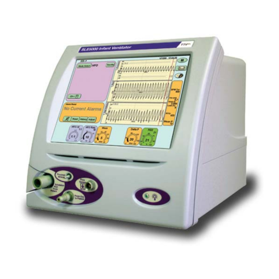
SLE5000 / SLE4000 User manual Version 5.0 software…
-
Page 2
All rights reserved. No part of this publication may be reproduced, stored in any retrieval system, or transmitted in any form or by any means, electronic, mechanical, photocopy, recording or otherwise, without prior permission of SLE. © Copyright SLE 29/04/2016 Manual: UM131 Issue 4 SLE Part Nº:… -
Page 3
How To Use The SLE5000/SLE4000 Infant Ventilator The warnings on pages 24 to 27 must be read and understood before using the SLE5000/SLE4000 ventilator. Failure to do so could lead to injury or death of the patient. WE RECOMMEND THE VENTILATOR BACK-UP POWER SUPPLY IS FULLY CHARGED PRIOR TO USE: Page 68. -
Page 4
This page is intentionally blank. Page 4… -
Page 5: Table Of Contents
Contents 1. Introduction ……….10 4. Technical Description ……..20 About This Manual………10 5. User/Owner Responsibility ……21 Intended Use ………10 6. Warnings …………24 Intended Users ……..10 Operational Warnings ……24 2. What’s New in version 5 ……11 6.1.1 General ……….24 mode ……….11 plus 7.
-
Page 6
14.2.5 Sub-ambient Pressure Alarm in Non HFO 11. Loops, Trends & Waveforms ….54 Modes ……….. 74 11.1 Waveforms ……….54 14.2.6 HFO Only Ventilator Set Threshold Alarms 11.2 Loops ………… 55 (SLE5000 only) ……..74 11.2.1 Capturing, Retrieving & Deleting Loops.55 14.2.7 Patient Leak Alarm …….. -
Page 7
Unexpected Rise or Drop in Min P. 27.1 Bacterial filter, SLE Part Nº:N2029 (SLE5000 only)……..108 (Autoclavable)……..145 19.8 Continuing Positive Pressure ….108 27.2 Bacterial filter, SLE Part Nº: N2587/000/001 19.9 Leaking Fresh Gas ……..109 (Single use)……….145 19.10 High Patient Leak ……..109 28. Patient Circuits ………..146 19.11 Clean Flow Sensor ……..109… -
Page 8
29.4 Cleaning Method ……..151 31.1.14 Flow Sensor Disconnect Alarm ….. 168 29.4.1 Ventilator ……….151 31.1.15 Cycle Fail Alarm ……..168 29.4.2 Flow Sensor ………. 151 31.1.16 Functional Test of HFO Mode ….173 29.4.3 Exhalation block ……..151 31.1.17 Functional Test of HFO+CMV Mode .. -
Page 9
Introduction Page 9… -
Page 10: Intended Use
1. Introduction 1.2 Intended Use The ventilator is designed for use on patients up to 1.1 About This Manual 20kg, in conventional ventilation. In high frequency This user manual details the operation of the oscillation ventilation up to 20kg, dependant on lung SLE4000 and SLE5000 infant ventilators.
-
Page 11: What’s New In Version 5
2. What’s New in version 5 2.5 Cycle fail alarm with flow sensor connected 2.1 TTV mode plus The pressure waveform will display the cycle fail The TTV algorithm mode has been modified to alarm threshold in all conventional modes. The plus provide a more stable volume delivery.
-
Page 12: Default Flow Trigger Setting Of 0.6 L/Min
2.11 Default flow trigger setting of 0.6 l/ 2.14 Modified operation of Main Power Fail alarm The default setting for the flow trigger in the flow The user can now silence the main power fail alarm waveform window has been reduced from 2 l/min to by pressing the Reset button in the alarm panel.
-
Page 13: Description Of The Ventilation Modes
3. Description of the Ventilation 3.2 CPAP (without a flow sensor) Modes The ventilator generates a continuous positive airway pressure at a level set by the User. The ventilator has the ability to be used as either a pressure controlled, volume targeted ventilator, as a User sets the following:- pressure limited, time cycled ventilator, and the •…
-
Page 14
3.3 CMV 3.4 PTV Continuous Mandatory Ventilation Patient Triggered Ventilation In this mode the inspiratory cycle is initiated by the In this mode all the patient’s breath attempts are ventilator at a set BPM rate. The breaths are time pressure supported. Mechanical breaths are cycled. -
Page 15
3.5 PSV plus 3.5.1 PSV with TTV (Targeted Tidal Volume) This is as for basic PSV with Apnoea Support, Pressure Supported Ventilation where the inspiratory pressure shall be controlled by This is a pressure limited mode of ventilation in the ventilator to achieve the user set Vte (for which each breath is patient triggered and assisted breaths). -
Page 16: Simv
3.6 SIMV 3.6.1 SIMV with PSV SIMV with PSV allows the user to select the Synchronised Intermittent Mandatory termination sensitivity and pressure support level on Ventilation non SIMV breaths. Once a mechanical breath is The frequency of mandatory breaths is determined delivered to the patient, the flow to the infant rapidly by the BPM control.
-
Page 17: Hfo (Sle5000 Only)
3.7 HFO (SLE5000 only) High Frequency Oscillation In this mode, the ventilator shall deliver continuous high frequency oscillation. There is no patient interaction. • The User sets the following:- • HFO rate • HFO I:E ratio • Mean pressure • Pressure amplitude (Delta P) •…
-
Page 18: Simv With Ttv Plus
3.9 Overview of Conventional Ventilation Modes The following table is a brief description of the trigger, limit and cycle types for each conventional ventilation mode. Mode Trigger Limit Cycle CPAP CPAP with apnoea Time trigger Pressure limit Time cycled backup Time trigger Volume limit Time cycled…
-
Page 19
plus 3.12 HFO mean compensation 3.10 Detailed description of TTV , HFO MAP Compensation & Automatic The ventilator includes a compensation algorithm Leak Compensation in PSV modes that closely maintains the set mean airway pressure when the Delta P is increased/decreased. plus 3.10.1 TTV In certain situations the mean airway pressure may… -
Page 20: Technical Description
Pressure is monitored via the proximal airway port 4. Technical Description through a pair of pressure transducers with data The ventilator is a computer controlled ventilator. being sent to the monitor subsystem. The computer is broken down into three electronic subsystems that are housed in the upper Flow is monitored by a dual hot wire anemometer (electronic) section of the ventilator.
-
Page 21: User/Owner Responsibility
SLE, or parts which are otherwise approved by SLE. Equipment which is not functioning correctly or is…
-
Page 22
This page is intentionally blank. Page 22… -
Page 23
Operational and Clinical Warnings Page 23… -
Page 24: Warnings
12 The ventilator contains temperature dependant 6. Warnings devices which perform normally in controlled environments in hospitals. However if the 6.1 Operational Warnings ventilator has been stored at a temperature The following warnings must be read and different to that in which it will be used, allow the understood before using the ventilator.
-
Page 25
6.1.1.2 Humidifier / Patient Circuit 43 Use only SLE approved patient circuits. On no 31 The functioning of this machine may be account should antistatic or electrically adversely affected by the operation of equipment conductive tubing be used. -
Page 26
It should be autoclaved as described in circuit to come into contact with the patient. the Cleaning and Disinfection Procedure prior to initial use. Use only SLE approved flow sensors 49 Do not allow heated section of the patient circuit (Part number: N5402). -
Page 27: Clinical Warnings
7. Clinical Warnings Failure to take corrective action when the alarms are activated could result in injury or death to the patient. 7.1 Monitoring The minimum patient monitoring requirements are: 1 ECG/heart rate. 2 Blood pressure (either by invasive or non invasive means).
-
Page 28
This page is intentionally blank. Page 28… -
Page 29
Ventilator Description Page 29… -
Page 30: Ventilator Description
8. Ventilator Description Rear Cover Front cover Touchscreen Power On Flow Sensor Connector Exhalation Block Flap Proximal Airway Port Fresh Gas Port Exhalation Block Front View Page 30…
-
Page 31
Fuse Holder Power Switch RS232 & Viewlink Connector Exhaust port for Exhalation Block Cell cover Cooling louvres Oxygen Supply Inlet Mains Power Cable Air Supply Inlet Rear View Page 31… -
Page 32
Silencer Guide Silencer Exhalation Block Clamp Exhalation Block Exhalation Block Port Page 32… -
Page 33: Description Of Symbols And Buttons
9. Description of Symbols and Symbol Description Buttons Enables the HFO activity panel. Enables the Mode Select panel. Symbol Description Type BF connection (Situated on Enables the Pressure Support front panel). panel. Night mode and Screen Lock. Caution: Consult instructions for Return button.
-
Page 34
A table explaining all abbreviations within this Symbol Description manual can be found on page 194. Pressure wave window with Flow versus Pressure loop display. Pressure wave window with Volume versus Pressure loop display. Pressure wave window and Flow wave window. Pressure wave window and Tidal Volume wave window. -
Page 35
User Interface Description Page 35… -
Page 36: User Interface
10. User Interface 10.2 Description of User Interface Indicators Caution: Do not use a sharp instrument, such In the mode panel the as a pen to activate the touchscreen controls user will find indicator as the excessive pressure applied by the lights next to functions point will damage the touchscreen that can be turned ON…
-
Page 37
Select the required 10.3.1.3 Up / Down Arrows The arrows appear when a function or parameter mode. The mode which can be modified is selected. selected will be highlighted by a colour change (from light green to dark green). The up arrow increases the chosen value and the Touch the confirm down arrow decreases the value. -
Page 38: Description Of The Mode Panel In Ventilation Off Mode
10.4 Description of the Mode Panel in 10.5.1 Oxygen Alarm Test Ventilation Off Mode The Oxygen Alarm Test button The Mode panel functions vary between modes of ventilation and “Ventilation Off”. activates the Oxygen Mode Panel in Ventilation Off Mode Alarm Testing panel.
-
Page 39: Flow
10.6.1 Flow 10.6.4 Alarm Volume On pressing the On pressing the Flow button (D) Volume Control button the Calibrate Flow (G) the Alarm Volume Sensor panel will panel will be be displayed. The displayed. Calibrate button The alarm volume (I) runs the panel allows the user calibration routine to set the alarm…
-
Page 40: Language Toggle
Displayed on this 10.6.8 Waveform Display Sync panel are four The Waveform buttons: Display Sync button (M) Language Toggle overlays the button (L) waveforms from Waveform Display one sweep with Sync button (M) that from the next. See Set Time and “Waveforms”…
-
Page 41: Version Information Panel
10.6.10 Version Information Panel 10.6.12 Controller Services The Version Caution: The controller services should only button (O) be used by Qualified Service Personnel. advances the user to the Version On pressing the Information panel. Controller button (Q) the Controller services panel will be displayed.
-
Page 42: Mode Panel Functions In A Ventilation Mode
10.7 Mode Panel Functions in a Ventilation Mode The panel also displays software version numbers and the controller checksum for the controller For each ventilation mode, extra mode specific subsystem. The Elapsed time counter shows the functions are displayed in the panel (except HFO accumulated days and hours the ventilator has Only).
-
Page 43: Standby Button (All Modes)
10.7.1 Standby Button (All modes) 10.7.2.1 Disabling the Apnoea alarm in CPAP The user has the The Standby button ability to disable the (X) suspends the Apnoea alarm. When current mode of the flow sensor is ventilation for 90 disconnected in CPAP seconds.
-
Page 44: Apnoea Setup For Ptv & Psv And Simv
10.7.3 Apnoea Setup for PTV & PSV and SIMV For PTV, PSV and Warning: Disabling of the alarm in SIMV has SIMV the Apnoea been allowed, so the user can use the setup button only ventilator non-invasively. The ventilator becomes active when should not be used invasively with the the backup breath rate is 9 BPM or lower.
-
Page 45: Set Trigger For Cpap, Psv, Ptv Simv
10.7.5 Set Trigger for CPAP, PSV, PTV & SIMV 10.7.7 Pressure Support in SIMV The Set Trigger The Pressure Support button (AA) panel allows the user activates the to set the Provide breath detection Support at percentage threshold in the ∆…
-
Page 46: Alarm Panel
When an alarm 10.8 Alarm Panel condition is active the The Alarm Panel panel flashes between displays all the alarm red and yellow, messages. indicating an alarm When no alarms are has been triggered. active the panel The panel will only show the highest priority alarm. displays the text “No More than one alarm can be active at the same DD EE…
-
Page 47: Default Waveform Windows
The ventilator can also 10.9 Default Waveform Windows display loops and The windows display the waveforms and loops trends. These are generated during ventilation. accessed from the The default waveform layout. Waveform Display Option button The button activates the Loops and Waveforms panel.
-
Page 48
Minute volume graph (selected from graph options 10.11 How to Set an Alarm Threshold button) To adjust an alarm threshold press the Adjust button in the High Minute Volume alarm panel. If no alarm condition is Low Minute Volume present the user will have to select the alarm threshold for modification. -
Page 49
The first method is by using the up and down arrow Note: The High and Low Pressure Alarm keys in the lower right-hand corner of the screen. thresholds auto track the pressure waveform by 5mbar for conventional modes of Note: The user can only adjust the alarm ventilation and 10mbar for HFO modes. -
Page 50: Ventilation Parameters
The parameters can be selected and modified in the 10.12 Ventilation Parameters same way as in the preview mode. Each ventilation mode has a number of parameters that have to be changed to meet the clinical requirements. The interface displays the user In the preview mode the definable parameters at the bottom of the parameters panel displays…
-
Page 51: Lung Mechanics And Measurement Panel
10.13 Lung Mechanics and IE Ratio Measurement Panel Inspiratory to Expiratory ratio. A calculated value This panel displays the measured and calculated derived from the user set inspiratory time against ventilation parameters. When no flow sensor is the time divided by the user set BPM minus the fitted only non flow based values are displayed.
-
Page 52: The Pause Button
10.14 The Pause Button The Pause button is Is a gas transport coefficient. A calculated value located in the top based on tidal volume and frequency. Value right hand corner of smoothed with a filter (time constant equal to 3 the screen.
-
Page 53
Loops, Trends & Waveforms Page 53… -
Page 54: Loops, Trends & Waveforms
When changing the ventilatory parameters the axis 11. Loops, Trends & Waveforms in the windows autoscale to best display the patient This chapter details the way the ventilator displays data. patient data. The ventilator displays the real time data collected from the proximal airway pressure The ventilator displays the waveforms within each transducer and ET manifold mounted flow sensor, to window in real time.
-
Page 55: Loops
11.2 Loops The ventilator displays the following three loops: Note: When viewing a stored loop the active flow versus volume, flow versus pressure and loops are shown as grey lines. volume versus pressure. Step 3. Pressing the open folder button will The ventilator draws three loops before refreshing hide the stored loop and the ventilator will the window.
-
Page 56: Trends
11.3 Trends 11.3.2 Description of Trend Windows The example window is that of Max pressure The ventilator can display eight different trends, against time. these being Minute Volume, Max Pressure, Mean Pressure, Min Pressure, O %, DCO , Resistance and Compliance against time. The ventilator stores 24 hours of trend data for all six trend types in a memory buffer.
-
Page 57
Ventilator Set-up Page 57… -
Page 58: Ventilator Set-Up
12. Ventilator Set-up Step 3. Fit the Exhalation Block and Silencer to the Gas Manifolds 12.1 Preparing the Ventilator for Use To prepare the ventilator for setup and later patient ventilation, carry out the following steps. If commissioning the ventilator for the first time please refer to the installation chapter in the Technical Information section of this manual.
-
Page 59
Heater wire connector Water trap Humidifier Connect the SLE approved patient circuit as shown in the diagram above (E). Ensure the ET manifold is occluded. Caution: Ensure that all the conical connectors are pushed together tightly. Note: Patient circuit type and design may vary from the diagram Setup the humidifier as per the manufacturer’s… -
Page 60: Ventilator Power Up And Power Down
12.2 Ventilator Power Up and Power 12.3 Back-up Battery Charging Down. Prior to first use, the ventilator should be connected to a suitable power outlet that is ON for a minimum 12.2.1 Mains power indicator. of 24 hours. The ventilator does not need to be The ventilator has a LED indicator on the front facia turned on to charge the battery.
-
Page 61: Battery Indicator
12.4 Battery indicator 12.5 Suspension of the “Main Power Fail” alarm. The software now has two icons in the top left hand corner of the screen. The user can suspend the Mains Power fail alarm by pressing the Reset button when the “Main Power Fail”…
-
Page 62: Extended Storage
12.6 Extended storage 12.6.1 Screw cap fuse holder 1. Open the side flap and slide the rear cover If the user is intending to store the ventilator for a towards the rear of the machine to expose the period greater than 40 days and is unable to charge battery fuse holder on the left hand side of the the batteries during this time as recommended in machine (when viewed from the rear).
-
Page 63
Pre-use test Page 63… -
Page 64: Pre-Use Test
65, then the unit should not present. (PASS/FAIL) be used until it has been repaired. Please contact an SLE approved engineer, or SLE. d) Connect the oxygen hose to the supply. e) The “No Air” alarm should be triggered. (PASS/…
-
Page 65: Pre-Use Test Checklist
13.1 Pre-use test checklist Symptom Possible Cause User remedy Step 3a) Pass — The ventilator does not turn 1. Batteries are completely 1. Remove the ventilator from continue discharged. service. & charge batteries. to step 3b 2. Batteries are 2. Remove the ventilator from disconnected.
-
Page 66
This page is intentionally blank. Page 66… -
Page 67
Operational Considerations Page 67… -
Page 68: Operational Considerations
14. Operational Considerations 14.1.4 Gas Input Pressures The ventilator requires the gas input pressures to be 14.1 General between 4-5bar. The ventilator can operate with the gas pressures at 3-4bar, but when there is a high 14.1.1 Ventilation Off Mode demand for gas, No O Supply or No Air Supply alarms can be triggered.
-
Page 69: Parameter Memory
14.1.7 Parameter Memory 14.1.12 HFO variable I:E ratio The user should be aware that the ventilator will The variable I:E ratio allows the user to increase the remember user parameter settings when switching expiratory phase in proportion to the inspiratory between modes, except when switching between a phase by the indicated ratio 1:2 or 1:3.
-
Page 70: Breath Detection
14.1.14 Breath Detection plus 14.1.16.2 Continuing without flow with TTV When the user disconnects the flow sensor when The breath detection threshold needs to be set in all ventilating in a mode with TTV ON, the ventilator plus patient interactive modes. sets the PIP level to the last used PIP level form the Setting the breath detection threshold at its most MAX PIP control (Note: This is not the set MAX PIP)
-
Page 71: Wave Shaping
14.1.17 Wave Shaping 14.1.18 Flow sensor removal for suctioning or re- The ventilator allows the user to modify the wave calibration, pausing ventilation shape. Under certain settings the ventilator can on the removal of the ET tube from the flow sensor (for To modify the wave endotracheal suctioning as an example) trigger the shape the user…
-
Page 72: Flow Sensor Removal For Suctioning Or
14.1.19 Flow sensor removal for suctioning or re- 14.1.20 BPM Tot. Measurement. calibration but continuing ventilation The ventilator measures BPM in two different ways, If the user requires to keep the patient ventilated with and without a flow sensor. whilst carrying out suctioning the following When used without a flow sensor, the ventilator procedure for circuit disconnection should be used.
-
Page 73: Alarms
14.2 Alarms Crossing the 5mbar ventilator set threshold If the high or low alarm threshold is exceeded by 14.2.1 High and Low Alarm Operation more than 5mbar the ventilator drops the fresh gas The high and low alarm thresholds warn the user to supply for 3 seconds.
-
Page 74: Minute Volume Alarm Threshold
14.2.2 Minute Volume Alarm Threshold 14.2.6 HFO Only Ventilator Set Threshold The default values for the alarm thresholds are: Alarms (SLE5000 only) Low Vmin alarm set to 0ml The user needs to be made aware that in HFO Only High Vmin alarm set to 18000ml mode the ventilator sets 6 alarm thresholds that are invisible to the user.
-
Page 75: Patient Leak Alarm
14.2.7 Patient Leak Alarm 14.2.8 Reset Contamination Alarm The user can modify The ventilator monitors the flow sensor continually the percentage at to ensure that it has not become contaminated. which the patient leak Contamination is regarded as the build up of alarm is triggered or secretions on the sensor wires, or flooding of the turn off the alarm all…
-
Page 76: Patient Circuits, Humidification And Nitric Oxide Therapy
When using autofeed humidification chambers the N4110 connected in parallel with a dual exhaust waterbag should be mounted higher than the max hose assembly SLE part Nº N4110/10) fitted to the Delta P or MAX PIP being used. exhalation block (remove the silencer). This is supplied as a complete kit under SLE part Nº…
-
Page 77: Nebulization Of Medication
Step 13 Re-fit the flow sensor between the ET Operational Changes manifold and the ET tube. When using the SLE4000/5000 with a nebulizer, the Step 14 Adjust the PIP and PEEP to compensate ventilator should be used as time cycled pressure for the decreased flow of gas through the limited device by removal of the flow sensor.
-
Page 78
This page is intentionally blank. Page 78… -
Page 79
Flow and Pressure Triggering Page 79… -
Page 80: Flow And Pressure Triggering
and measurement panel the Trigger value flashes 15. Flow and Pressure Triggering white. 15.1 Breath Detection Threshold (Flow 15.2 Breath Trigger Sensitivity Triggering) (Pressure Triggering) When the ventilator is used with a flow sensor the The ventilator was designed primarily to be used flow waveform window contains a breath detection with the flow sensor, but the ventilator can be threshold.
-
Page 81: Setting The Pressure Trigger Level In Cpap, Simv, Ptv And Psv
15.3 Setting the Pressure Trigger Level in CPAP, SIMV, PTV and PSV Note: The setting of the pressure trigger level can only be carried out once the ventilator is connected to a patient. Note: The Breath trigger sensitivity defaults to midway between min and max. The procedure is the same for CPAP, SIMV, PTV and PSV.
-
Page 82
This page is intentionally blank Page 82… -
Page 83
Basic Setup Page 83… -
Page 84: Basic Set-Up
For CMV see section 16.4 on page 87. choice of ventilator settings. For PTV see section 16.5 on page 89. Note: Only SLE approved circuits should be For PSV see section 16.6 on page 91. used with this ventilator. For SIMV see section 16.7 on page 93.
-
Page 85: Cpap Set-Up
16.3 CPAP Set-up 16.3.1 Actions after connection to patient in CPAP Step 1. From the Step 4. To adjust the Apnoea alarm delay and to Mode Select panel activate backup breaths in the event of Apnoea select CPAP. press the Apnoea Setup button on the Mode Panel. The Apnoea Alarms Settings panel should now be displayed.
-
Page 86: Ttv Plus (Volume Targeting) Of Backup
Step 10. If TTV (volume targeting) of the backup plus plus 16.3.3 TTV (Volume targeting) of backup breaths is required, turn on the function and set the breaths in CPAP. Max PIP and the Vte (TTV) (Targeted Tidal When the user selects TTV the PIP control plus Volume).
-
Page 87: Cmv Set-Up
16.4 CMV Set-up 16.4.1 Actions after connection to patient in Step 1. From the Step 4. The High and Low Pressure Alarm Mode Select panel thresholds auto track the pressure waveform by 5 select CMV. mbar. The alarm thresholds can be adjusted if required.
-
Page 88: Ttv Plus (Volume Targeting) All Mechanical
plus 16.4.4 Ventilation without a flow sensor 16.4.3 TTV (volume targeting) all mechanical connected. breaths in CMV. When the ventilator is used without the flow sensor When the user selects TTV the PIP control plus connected, the user will have to set the “Cycle Fail” becomes the MAX PIP control.
-
Page 89: Ptv Set-Up
16.5 PTV Set-up 16.5.1 Actions after connection to patient in PTV Step 4. Adjust the Backup parameter to Step 1. From the Mode the desired BPM rate. Select panel select PTV. Step 5. If the backup breath rate is 9 BPM or lower the Apnoea setup is activated.
-
Page 90: Interactive And Limiting Controls In Ptv
Step 11. If TTV (volume targeting) of the triggered 16.5.2 Interactive and limiting controls in PTV. plus and mechanical breaths is required, turn on the The user needs to be aware that the following function and set the Max PIP and the Vte (TTV) controls interact.
-
Page 91: Psv Set-Up
16.6 PSV Set-up 16.6.1 Actions After Connection to Patient in Step 1. From the Step 4. Adjust the Backup parameter to Mode Select panel the desired BPM rate. select PSV. Step 5. If the backup breath rate is 9 BPM or lower the Apnoea setup is activated.
-
Page 92: Interactive And Limiting Controls In Psv
16.6.2 Interactive and limiting controls in PSV. The user needs to be aware that the following plus Note: When TTV is discontinued the Max controls interact. PIP returns to the last used PIP as shown in The PEEP control interacts with the PIP control. the MAX PIP parameter control (Not the set When increasing the PEEP, the PIP will track MAX PIP) or with a minimum of 5 mbar above…
-
Page 93: Simv Set-Up
16.7 SIMV Set-up 16.7.1 Actions After Connection to Patient in SIMV Step 1. From the Mode Step 4. Adjust the BPM parameter to Select panel select the desired BPM rate. SIMV. Step 5. If the backup breath rate is 9 BPM or lower the Apnoea setup is activated.
-
Page 94: Interactive And Limiting Controls In Simv
the default waveform display. 16.7.2 Interactive and limiting controls in SIMV. The user needs to be aware that the following Note: The user cannot set the high and low controls interact. minute volume alarms when the flow sensor The BPM and Ti controls interact. Increasing the is not connected.
-
Page 95: Ventilation Without A Flow Sensor Connected
plus Note: If TTV is ON the termination sensitivity and provide support values for non SIMV breaths will only come into effect if the targeted tidal volume could not be reached. 16.7.4 Ventilation Without a Flow Sensor Connected. When the ventilator is used without the flow sensor connected, the user will have to set the Breath Trigger Sensitivity and the Cycle Fail alarm.
-
Page 96: Hfo Only Set-Up (Sle5000 Only)
16.8 HFO Only Set-up (SLE5000 only) 16.8.1 Actions After Connection to Patient in Step 1. From the Step 4. Adjust the Delta P parameter as required. Mode Select panel select HFO Only. Note: Do not press the autoset button in the alarm panel until the required Delta P has been set.
-
Page 97: Interactive And Limiting Controls In Hfo
16.8.2 Interactive and limiting controls in HFO. The user needs to be aware that the following controls interact. The HFO I:E ratio & the Delta P control interact. When changing the HFO I:E Ratio the set Delta P can be reduced when the ratio is increased. Note: Decreasing the HFO I:E ratio will NOT increase the Delta P.
-
Page 98: Hfo+Cmv Set-Up (Sle5000 Only)
16.9 HFO+CMV Set-up (SLE5000 only) 16.9.1 Actions After Connection to Patient in HFO+CMV Step 1. From the Step 4. The user can Mode Select panel select which type of select HFO+CMV. HFO activity is required by pressing the HFO Activity Button on the Mode panel.
-
Page 99
Flow Sensor Care Page 99… -
Page 100: N5402-Rev2 & N5302 Flow Sensor
71 or ’14.1.19 Flow SLE offers two types of sensor the N5402-REV2 sensor removal for suctioning or re- which is a reusable sensor or the N5302 which is a calibration but continuing ventilation’…
-
Page 101: Cleaning And Sterilization Of The N5402-Rev2 Sensor
Sterilization For sterilization a validated steam 17.2 Cleaning and Sterilization of the sterilization according to BS EN554 N5402-REV2 Sensor can be applied. Autoclave at Remove the flow sensor connecting cable before 134ºC (277ºF) (Allowable variation of any cleaning, disinfection or sterilization. temperature of +3ºC) at 220kPa (32psi) with a minimum holding time of 3 minutes.
-
Page 102
This page is intentionally blank. Page 102… -
Page 103: Frequently Asked Questions
Frequently Asked Questions Page 103…
-
Page 104: Frequently Asked Questions
automatically returning to the ventilation mode. If 18. Frequently Asked Questions the user has completed the procedure before that time, simply pressing the “Standby” button will take 18.1 Ventilator Related Questions the user out of standby mode and back into the 18.1.0.1 What range of patients is the ventilator selected mode of ventilation.
-
Page 105: Mode Related Questions
18.1.0.10 When looking at the parameter 18.2 Mode Related Questions settings, what do I record? 18.2.0.1 What is meant by Targeted Tidal The setting in the upper right hand corner of the Volume? parameter window is what has been set. The The user selects the appropriate volume.
-
Page 106: Patient Circuits
18.3.0.4 Should bacterial filters be used on the expiratory limb? SLE recommends the use of a single use bacterial filter on the expiratory limb as a way of preventing contamination of the ventilator and the environment.
-
Page 107
Commonly Seen Alarms Page 107… -
Page 108: Commonly Seen Alarms
19. Commonly Seen Alarms 19.4 Low Tidal Volume The measured volume is below the selected alarm 19.1 High Pressure threshold. This can happen on switching between If the PIP is above the user set alarm threshold, this modes. When in triggered modes of ventilation, alarm is generated.
-
Page 109: Leaking Fresh Gas
19.9 Leaking Fresh Gas contaminated with secretions. The flow sensor must be removed and replaced with a sterile The alarm message “Leaking Fresh Gas” means flow sensor. The contaminated sensor must that fresh gas to the patient is leaking somewhere. then be cleaned according to the guidelines laid This must not be confused with the alarm message out the in the user manual.
-
Page 110
This page is intentionally blank. Page 110… -
Page 111
Troubleshooting Chart Page 111… -
Page 112: Troubleshooting Chart
20. Troubleshooting Chart 20.1 Ventilation Related Problems Warning: In all alarm conditions check the patient first. Symptom Possible Cause Remedy Tidal volume maintained Flow sensor incorrectly calibrated. Calibrate flow sensor. despite low PIP. Blocked Fresh Gas Fresh gas supply tube blocked or Check the fresh gas supply line and alarm.
-
Page 113
Symptom Possible Cause Remedy Unexpected rise in max The maximum pressure has increased Check ventilator pressures. P alarm. by more than 5mbar. Check the patient circuit. Press autoset to for new alarm Alarm Message: thresholds. Unexpected Rise in Max P. Unexpected drop in max The maximum pressure has Check ventilator pressures. -
Page 114: Ventilator Related Problems
Symptom Possible Cause Remedy Breath not detected ET tube blocked or disconnected. Check the patient for air entry. alarm. Check the patient circuit. Alarm Message: Breath Not Detected. High alarm threshold Alarm threshold set very high. Set alarm threshold closer to does not move from top Check numerical value against waveform.
-
Page 115
Symptom Possible Cause Remedy Touchscreen buttons do Touching the screen at two points. Touch the screen at one point only not operate as expected. Touchscreen out of alignment. Refer ventilator to qualified service personnel. Touchscreen buttons do Touchscreen failure. Remove patient to alternative form of not operate. -
Page 116
Symptom Possible Cause Remedy Leaking fresh gas alarm Air and Oxygen supply failed. If generated whilst connected to a with CPAP/PEEP/Mean patient, remove patient to alternative at zero and PIP/Delta P form of ventilation. at zero. Check Air and Oxygen Alarm Message: supplies/connections. -
Page 117
Symptom Possible Cause Remedy System fail alarm A hardware/software fault has Remove patient to alternative form of developed within the ventilator. ventilation, then remove ventilator from service. Alarm Message: Note alarm message and refer System Fail ventilator to qualified service (Monitor Isolated personnel. -
Page 118
Symptom Possible Cause Remedy User interface failure Internal hardware reset has occurred. Remove ventilator from service. alarm. If generated whilst connected to a patient, remove patient to alternative Alarm Message: form of ventilation User interface failure. Note alarm message and refer ventilator to qualified service personnel. -
Page 119
Symptom Possible Cause Remedy Oxygen calibration During the oxygen sensor calibration Remove patient to alternative form of failure. the ventilator could not achieve a ventilation, then remove ventilator reading of 100% oxygen. from service. Alarm Message: Note alarm message and refer Oxygen Calibration ventilator to qualified service Fail. -
Page 120
This page is intentionally blank Page 120… -
Page 121: Technical Information
Technical Information Page 121…
-
Page 122: Installation
If unsure on how to commission the ventilator refer the unit to qualified service personnel or contact the SLE service department. Caution: Failing to install the supplied water trap* will increase the risk of liquid contamination.
-
Page 123: Ventilator Mounting
21.2 Ventilator mounting. 21.3 Back-up battery connection The ventilator needs to be secured to the trolley with The internal back-up batteries need to be connected the screws and washers provided in the fittings prior to use. Remove the rear cover to reveal the pack.
-
Page 124: Mains Cable Attachment
21.5 Mains cable attachment 21.6 Water trap attachment Attach the mains cable as follows. Fit the water trap as follows. a. Remove the dust caps. b. Screw on the Water Trap to the Air inlet. Tighten the nut by hand only. Note: The mains lead is found in the language pack.
-
Page 125: Secondary Language Selection
NOT in use. The process requires the ventilator to exit the user interface and enter * Please contact SLE or your distributor for the Language Selection Program. The information on the availability of secondary ventilator will need to be restarted.
-
Page 126: Oxygen Calibration Routines
23. Oxygen Calibration Routines The ventilator has two oxygen cell calibration routines. The first calibration is the 100% oxygen calibration (one point). This calibration is carried out at the following intervals after the unit is turned on: start up, 10 minutes, 30 minutes, 60 minutes, 90 minutes and then at 8 hourly intervals.
-
Page 127: Functional Testing & Preventative Maintenance Schedule
C Warning: Preventative Maintenance, Overhaul and Calibration of this ventilator should only be carried out by a SLE trained hospital engineer or an SLE service engineer. 24.1 Functional testing Every three months the user shall perform the …
-
Page 128: Rs232
25. RS232 25.3 Overview This section describes the data format and 25.3.1 Data and Pinout Description. connections for the serial interface of the infant Data Format: RS232-C compatible, 19200 bps, 8 ventilator. data bits, 1 stop bit, no parity. The data output is a 25.1 Cautions for RS232 comma delimited ASCII text string terminated by carriage return and linefeed (<CR>,<LF>).
-
Page 129: Parameter Descriptions And Format
25.3.3 Parameter Descriptions and Format The text string outputted contains 41 parameters. e.g. 60,2,6,10,23,100,4,2,100,1,20,0,45,20,30,160,280, 0,45,0,15000,60,3,10,145,139,3,25,99,22,13,0,824, 10,3275,6,39,280,64 A description of each parameter follows; 25.3.4 List of Parameters Param. Description Units Details Nº Set BPM breaths/minute 1 to 150 Set CPAP mbar Set CPAP pressure 0 to 20 mbar Set Tidal Volume 0.2 ml…
-
Page 130
Param. Description Units Details Nº Set Patient Leak Alarm Percentage leak at which alarm occurs. 10 to 50%. Values above 50 = alarm off. Set Apnoea Alarm seconds 5 to 60 seconds Set Low Pressure Alarm 0.1 mbar -1200 to 1100 (-120 to 110 mbar) Set Cycle Fail Alarm 0.1 mbar 0 to 1150 (0 to 115 mbar) -
Page 131: Table Of Current Alarm Condition Codes
25.3.5 Table of Current Alarm Condition Codes. No O2 Supply Value Currently Displayed alarm condition No Air Supply No Current Alarms No Gas Oxygen Cell Disconnected Max. Pressure too low Calibrate Oxygen Cell Fresh Gas Solenoid Fail Oxygen Cell Exhausted Controller Failure — control subsys.
-
Page 132: Alarms
26. Alarms 26.1 Alarm Protocols The following descriptions summarize the alarms to be generated by the ventilator. The alarms are sorted by their priority ratings. An alarm of a high priority can interrupt a medium priority alarm, effectively, masking medium priority alarms. Upon the generation of alarms a message indicating the type of alarm will be displayed and then an audible alarm with the correct priority level is generated.
-
Page 133: Alarm Descriptions And Actions To Be Taken
26.3 Alarm descriptions and actions to be taken Alarm 3. Sub-Ambient Pressure Alarm message ….Sub Ambient Pressure Alarm sub message ….. Safety shutdown Alarm 1. Monitor Failure activated and Alarm message….Monitor EEPROM ventilator restarting Fail Priority of alarm….3 Alarm sub message…..
-
Page 134
Alarm 5. 101 System Fail (Memory Checksum Alarm 8. 104 System Fail (Memory Checksum Error) Error) Alarm message ….Monitor EEPROM Alarm message ….Monitor EEPROM fail fail Alarm sub message …..Monitor checksum Alarm sub message….Monitor checksum Fail Fail Alarm code ……101 Alarm code ……104 Priority of alarm ….5 Priority of alarm ….8… -
Page 135
Alarm 11. Continuing Positive Pressure Alarm 13. Low Pressure Alarm message….Continuing Positive Alarm message ….Low Pressure Pressure Alarm sub message ….. Pressure below low Alarm sub message….. Check the patient alarm threshold circuit Priority of alarm….13 Priority of alarm ….11 Monitor mode ……. -
Page 136
Alarm 15. Cycle Fail Alarm 17. Unexpected Rise in Mean P Alarm message ….Cycle Fail Alarm message ….Unexpected Rise in Mean P. Alarm sub message …..Mechanical Breath was not detected at Alarm sub message….Press AUTOSET to adjust HFO alarms to new pressures Priority of alarm ….15 Priority of alarm ….17 Monitor mode …….All… -
Page 137
Alarm 19. Unexpected Rise in Max P Alarm 21. Unexpected Rise in Min P Alarm message….Unexpected Rise in Alarm message ….Unexpected Rise in Max P. Min P. Alarm sub message….. Press AUTOSET to Alarm sub message ….. Press AUTOSET to adjust HFO alarms adjust HFO alarms to new pressures… -
Page 138
Alarm 23. No Gas Alarm 25. No Air Supply Alarm message ….No Gas Alarm message ….No Air Supply Alarm sub message …..Connect ventilator Alarm sub message….Connect air supply to gas to ventilator Priority of alarm ….23 Priority of alarm ….25 Monitor mode …….All Monitor mode …….All Can alarm be muted ….No… -
Page 139
Alarm 28. Blocked Fresh Gas Alarm 31. System Fail (Isolate System Error) Alarm message….Blocked Fresh Gas Alarm message ….System Fail Alarm sub message….. Fresh gas supply to Alarm sub message ….. Monitor isolated patient may be system fail blocked Priority of alarm…. -
Page 140
Alarm 34. Clean Flow Sensor Alarm 37. Calibrate Flow Sensor Alarm message ….Clean Flow Sensor Alarm message ….Calibrate Flow Sensor Alarm sub message …..Flow sensor is contaminated Alarm sub message….Calibration is required Priority of alarm ….34 Priority of alarm ….37 Monitor mode …….Flow Monitor mode …….Flow Can alarm be muted ….Yes… -
Page 141
Alarm 40. High Patient Leak Alarm 43. Low Minute Volume Alarm message….High Patient Leak Alarm message ….Low Minute Volume Alarm sub message….. Check Patient Alarm sub message ….. Minute volume Connection below low threshold Priority of alarm ….40 Priority of alarm…. -
Page 142
Alarm 46. Apnoea (Pressure) Alarm 48. Fresh Gas Solenoid Fail Alarm message ….Apnoea Alarm message ….Fresh Gas Solenoid Fail Alarm sub message …..Period between patient effort Alarm sub message….REMOVE exceeds Apnoea VENTILATOR limit FROM SERVICE Priority of alarm ….46 Priority of alarm ….48 Monitor mode …….Pressure Monitor mode …….All Can alarm be muted ….Yes… -
Page 143
Alarm 50. Calibrate Oxygen Cell Alarm 52. Oxygen Calibration Fail Alarm message….Calibrate Oxygen Alarm message ….Oxygen calibration Cell fail Alarm sub message….. The oxygen cell Alarm sub message ….. Check Oxygen needs calibrating supply Priority of alarm ….50 Priority of alarm…. -
Page 144: Software And System Fail Protocols
Alarm 54. Low Oxygen Level Alarm 57. Complete Power Fail Alarm. Alarm message ….Low Oxygen Level Type……..Audible Only Alarm sub message …..The Oxygen level is Can alarm be muted ….No lower than set Alarm Description: Priority of alarm ….54 If both mains and battery power fail this alarm is Monitor mode …….All sounded.
-
Page 145: Bacterial Filters
27. Bacterial Filters 27.2 Bacterial filter, SLE Part Nº: N2587/ 000/001 (Single use) It is recommended that bacterial filters are fitted in the fresh gas supply and on the patient side of the This single use bacterial filter is fitted onto the exhalation block.
-
Page 146: Patient Circuits
28. Patient Circuits The ventilator can use both single use and autoclavable patient circuits. 28.1 Warnings for Patient Circuit Use. Use only SLE approved patient circuits. Applicable to single use and re-usable patient circuits. Make sure that all connections are made properly and are tight before use.
-
Page 147: Generic 10Mm Re-Usable Patient Circuit
It is designed for use in combination with a Servo controlled humidifier. Clean and sterilize before and after use. It is recommended that a high quality bacteria filter (SLE part no. N2029) is fitted at the fresh gas connection to the humidifier inlet, however the circuit may be used without.
-
Page 148: Generic 10Mm Single Use Patient Circuit
28.3 Generic 10mm Single Use Patient Circuit It is recommended that a high quality bacteria filter (SLE part No. N2029) is fitted at the fresh gas connection to the humidifier inlet, however the circuit may be used without. Connect the patient circuit as shown in the diagram and described below.
-
Page 149: Generic Nitric Oxide Delivery Adaptor Kit
28.4 Generic Nitric Oxide Delivery Adaptor Kit The kit is for single patient use. It is designed to be used with an SLE approved patient circuit, in combination with a Servo controlled humidifier and an Inhaled Nitric Oxide Delivery System.
-
Page 150: Cleaning, Disinfection And Sterilization
62°C. DO NOT immerse any part of the ventilator in any liquid, with the exception of the expiratory exhalation block (SLE part No N6622). 29.1 Preparation of a New Ventilator 29.3 Cleaning, Disinfection &…
-
Page 151: Cleaning Method
29.4 Cleaning Method 29.5 Disinfection Method Note: Cleaning is an essential prerequisite to Note: Alcohols such as 70% isopropanol have disinfection and sterilization. a good activity against bacteria and viruses. They should only be used after all visible 29.4.1 Ventilator surface dirt has been removed from the area to be disinfected.
-
Page 152: Technical Specification
30. Technical Specification 30.1.3 PTV This section summarizes the specification of the Inspiratory Time: 0.1 to 3.0 seconds ventilator in terms of the modes, ranges and limits (Resolution 0.01 seconds) that are required on the controls and the displays. It CPAP Pressure: 0 mbar to 20 mbar also summarizes the mechanical and electrical…
-
Page 153: Simv
30.1.5 SIMV 30.1.6 HFO Ventilation BPM: 1 to 150 (Resolution 1BPM) HFO Only I:E Ratio: Calculated from BPM and Frequency Range: 3-20Hz. (1Hz resolution.) Inspiratory time settings. I:E Ratio 1:1 / 1:2 / 1:3 (11.2:1 to 1:600) Delta Press Range: 4 mbar to 160 mbar for 3.3 to Inspiratory Time: 0.1 to 3.0 seconds…
-
Page 154: Controls (Via Touchscreen Display)
30.1.8 Controls (Via touchscreen display) Flow button: Activates flow sensor calibration panel Adjust button: Activates alarm thresholds for modification Folder button: Retrieves loop from memory Alarm Auto-Track Sets selected % O Graphs button: Activates waveform and button: loops panels testing HFO activity Activates HFO activity panel Apnea Sup Button: Sends diagnostic pulse…
-
Page 155: Controls
PEEP parameter 0 to 20 mbar (Resolution 1 Waveform display Toggles waveform display control: mbar) sync button: synchronization PIP parameter 0 to 65 mbar (Resolution 1 Waveshaping Activates change wave shape control: mbar) button: panel Picture capture Stores loop to memory Zero button: Zeros seconds button…
-
Page 156: Pressure
Range: -10 mbar (Conventional)/ -70 30.2.3 Pressure mbar (HFO modes) to 10 Real Time Pressure: Resolution 1mbar, accuracy mbar below high-pressure ±1mbar threshold. Drift detection: detects drift when there is a Resolution: 0.5 mbar pressure difference of more High Tidal Volume: than 5mbar between the two pressure transducers.
-
Page 157: Patient Circuits
Set Insp Time For more details refer to the RS232 addendum. Set PIP Contact SLE for more details. Set O Compatibility with: Vuelink. Contact SLE for more details. Set HFO Delta P Set HFO Mean Set HFO Rate Ventilation Mode…
-
Page 158: Gas Supplies
30.7 Gas supplies 30.8 Power, Dimensions, Classification etc. The air and oxygen high pressure gas supplies are used as fresh gas. Voltage: 100-240V/ 50-60Hz Power: 115 VA 30.7.1 Oxygen supply Fuse: T2.0AH 250V (5x20mm) (Qty The ventilator requires a supply of pure oxygen between 2.8 to 6 bar Battery Backup 12 Volt up to 45-60 minutes…
-
Page 159
Functional Testing Page 159… -
Page 160: Functional Testing
Action: If the alarm fails to sound do not use the ventilator on a patient. Remove ventilator from service and contact an SLE approved engineer. Re-connect mains power. Turn ON the ventilator and wait for it to enter the Ventilation OFF mode.
-
Page 161: Back-Up Alarm Speaker Test
Action: If the beep fails to sound do not use flow sensor by holding it the ventilator on a patient. Remove ventilator between two fingers, from service and contact an SLE approved closing both ends as engineer. shown in the following picture.
-
Page 162: Oxygen Alarm Test
31.1.6 Oxygen Alarm Test Calibration” on page 126). If the fault Step 6. In Ventilation continues after calibration remove ventilator Off mode panel press from service and contact an SLE approved the Oxygen Alarm engineer. Test button. Further decrease the…
-
Page 163: Function And Alarm Testing
31.1.7 Function and Alarm Testing Step 9. Set the following parameters in the CPAP preview mode: 1 sec. CPAP 5 mbar 20 mbar After pressing the confirm button the user will be presented with the CPAP screen. Set the high alarm to 30 mbar Step 10.
-
Page 164
• If the fault continues after checking all possible causes, remove the ventilator Step 16. Gently constrict the proximal airway tube from service and contact an SLE approved so as to increase the pressure. Allow the pressure engineer. to increase but do not allow it to exceed the high alarm threshold. -
Page 165: High Pressure Alarm
If the fault continues after checking all necessary. possible causes remove the ventilator from If the fault continues after checking all service and contact an SLE approved possible causes remove the ventilator from engineer. service and contact an SLE approved engineer.
-
Page 166: Breath Not Detected Alarm
If the fault continues after checking all alarm panel of the possible causes remove the ventilator from alarm notification. service and contact an SLE approved engineer. Set the PEEP to 5 mbar. Action: If the “Breath Not Detected” alarm is not triggered perform the following actions.
-
Page 167: Mains Failure Alarm
If the gas supply is working correctly and the alarm still fails to trigger, remove the ventilator from service and contact an SLE approved engineer. Page 167…
-
Page 168: Flow Sensor Disconnect Alarm
If “Connect Flow Sensor Alarm” cannot be Flow Sensor” alarm is cancelled remove the ventilator from service activated, replacing and contact an SLE approved engineer. the “Connect Flow Sensor” alarm. If the ventilator passes these tests recalibrate the flow sensor, and then advance to Step 33.
-
Page 169
Step 35. Verify that: If the fault continues after checking all the the ventilator cycles, possible causes, remove the ventilator from service and contact an SLE approved the cycle waveform appears in the waveform engineer. windows, after 1 minute the BPM Tot should read 20 BPM in the breath parameter window. -
Page 170
SLE approved engineer. Top position Action: If the waveshape does not change as required, remove the ventilator from service and contact an SLE approved engineer. Page 170… -
Page 171
If the ventilator successfully passes all these tests after performing one of these actions, go to Step 47. • Replace the test lung with an SLE recommended test lung. • Check patient circuit is set up correctly as shown in Section 12: Ventilator Set-up. Pay close attention to proximal airway, fresh gas connection and the expiratory limb. -
Page 172
If the fault continues after checking all Set provide support to possible causes remove the ventilator from 75% of PIP and stop service and contact an SLE approved support at 40% of engineer. peak flow. Step 51. Set Pressure support to OFF… -
Page 173: Functional Test Of Hfo Mode
Check the test lung and replace if necessary. If the fault continues after checking all the possible causes remove the ventilator from service and contact an SLE approved engineer. Step 54. Verify that: the ventilator is oscillating, the oscillation waveform appears in the waveform windows.
-
Page 174
• Check the test lung and replace it if necessary. • If the fault continues after checking all possible causes remove the ventilator from service and contact an SLE approved engineer. • Re-calibrate the system • Check the software version and confirm it is correct. -
Page 175: Functional Test Of Hfo+Cmv Mode
• Check the test lung and replace if necessary. • Ensure threshold settings are correct. • Re-calibrate system. If the fault continues after checking all the possible causes, remove the ventilator from service and contact an SLE approved engineer. Page 175…
-
Page 176: Pressure Change Alarm
If the fault continues after checking all the you cannot find a fault, replace the possible causes, remove the ventilator from components of the patient circuit and try service and contact an SLE approved again. engineer • Check the test lung and replace if necessary.
-
Page 177
EMC table, Schematics & Overlays Page 177… -
Page 178: Emc Compliance
Compliance Electromagnetic environment- guidance RF emissions Group 1 The SLE4000/5000 uses RF energy only for its internal func- CISPR 11 tion. Therefore, its RF emissions are very low and are not likely to cause any interference in nearby electronic equip- ment.
-
Page 179: Electromagnetic Immunity
32.1 Electromagnetic immunity Guidance and manufacturer’s declaration — electromagnetic immunity The SLE4000 & SLE5000 is intended for use in the electromagnetic environment specified below. The customer or the user of the SLE4000 & SLE5000 should assure that it is used in such an environment. Immunity test IEC 60601 test level Compliance level…
-
Page 180: Recommended Separation Distances
Guidance and manufacturer’s declaration — electromagnetic immunity The SLE4000 & SLE5000 is intended for use in the electromagnetic environment specified below. The customer or the user of the SLE4000 & SLE5000 should assure that it is used in such an electromagnetic environment. Immunity test IEC 60601 TEST Compliance…
-
Page 181
32.2 Recommended separation distances between portable and mobile RF communications equipment and the SLE4000 & SLE5000 Recommended separation distances between portable and mobile RF communications equipment and the SLE4000 & SLE5000 The SLE4000 & SLE5000 is intended for use in an electromagnetic environment in which radiated RF disturbances are controlled. -
Page 182: Pneumatic Unit Schematic Sle4000 Model H, K & N
33. Pneumatic Unit Schematic SLE4000 Model H, K & N Below is a schematic representation of the pneumatic unit of the ventilator. Page 182…
-
Page 183: Pneumatic Unit Schematic Sle5000 Model G, G-R, J, L & M
34. Pneumatic Unit Schematic SLE5000 Model G, G- , J, L & Below is a schematic representation of the pneumatic unit of the ventilator. Page 183…
-
Page 184: Ventilator Labelling
35. Ventilator Labelling 35.1 SLE4000 model N Page 184…
-
Page 185: Sle5000 Model M-1
35.2 SLE5000 Model M-1 Page 185…
-
Page 186
This page is intentionally blank. Page 186… -
Page 187
Consumables & Accessories Page 187… -
Page 188: Consumables And Accessories
36. Consumables and Accessories Part No Item 10mm Patient Circuit (Single use). BC5188/100/15 Temperature probe port 100mm from ET tube. Box of 15 10mm Patient Circuit (Single use). BC5188/400/15 Temperature probe port 400mm from ET tube. Box of 15 10mm Patient Circuit (Single use) Dual Heated Wire. BC5488/DHW (Smooth bore).
-
Page 189
Part No Item Silencer (fitted to rear of exhalation block). N2186/01 Bacteria filter (autoclavable). N2029 Bacteria filter (single use). N2587/000/050 (complete) 4 metres length. N2035 Air hose, 4 bar (complete) 4 metres length. N2199 MR850 Humidifier Heater Base. (230V) For UK Only. N3850/00 MR850 Humidifier Heater Base. -
Page 190
Part No Item MR340 Re-usable chamber. N3340 Heater Adapter for use with Single Use patient N5603 circuits & chambers and MR730 Humidifier Heater Base. Dual Heater Adapter for use with Single Use patient N5604 circuits & chambers and MR730 Humidifier Heater Base. -
Page 191
N6670 hook and medi rail. (Shelf height 99cm). Patient Circuit Arm. N6627/212 Battery Fuse (10 Amp, 20 x 5mm ceramic, anti M0799/10 surge). User Manual for SLE4000/5000. (English) UM131/V05/UK Service Manual for SLE5000, Model G & G- N6645/G Page 191… -
Page 192
Part No Item Service Manual for SLE4000, Model H. N6645/H Service Manual for SLE5000, Model J. N6645/J Service Manual for SLE4000, Model K. N6645/K Service Manual for SLE5000, Model L. N6645/L Service Manual for SLE5000, Model M & M-1. N6645/M Service Manual for SLE4000, Model N. -
Page 193
Glossary Page 193… -
Page 194: Glossary Of Abbreviations Used In This Manual
37. Glossary of Abbreviations l/min Litres per Minute Used in this Manual mbar Millibar Millilitres ASCII (American Standard Code for Millisecond Information Interchange) is the most common format for text files in NEEP Negative End Expiratory Pressure computers. Not suitable for non- Mean P Mean Pressure English letters but suitable for…
-
Page 195: Index
Alarm, Low Tidal Volume 38. Index Alarm, Main Power Failure Alarm, Mains Failure Alarm, Monitor Failure Abbreviations, used in the manual Alarm, Monitor/Display Comms Fail Adjust Button, location Alarm, No Air Supply Air Hose, Part Number Alarm, No Gas Alarm panel location Alarm, No O Supply Alarm Panel, description of…
-
Page 196
C20/C, Value Gas Input Pressures Calibrate Oxygen Sensor Button, description of General Warnings. Graphs Button Change Wave Shape Button, description of Change Wave Shape panel Cleaning and sterilization HFO Activity Button, description of Cleaning prior to first use HFO Mean Compensation Cleaning when in service HFO mode, Functional test of Clinical Warnings… -
Page 197
Re-usable Patient Circuit Rise Time Hose, Part Number RS232 Parameter Control RS232 Cable Operating Environment RS232 Data and Pinout description Operational Warnings. RS232 location of Options and Service Data Button RS232 Parameter Descriptions Outputs Overhaul Schedule Oxygen — Clinical use. Sensor Contamination Oxygen — Fire Hazard. -
Page 198
Ventilation Off mode Ventilation related problems Ventilator control location 65, 114 Ventilator related problems Ventilator Setup Ventilator Warnings. Version info panel, description of Vmin(l), Value Vte (ml), Value Vte (TTV ) Vuelink Wave Form Display Options Wave forms Wave shaping 36, 47 Waveform display options Waveform Display Sync Button, description of… -
Page 199
SLE reserves the right to make changes without prior notice in equipment, publications and prices as may be deemed necessary or desirable. Page 199…
This manual is also suitable for:
4000
|
Сервисная инструкция на ИВЛ SLE-5000 |
||||||
|
||||||
|
||||||
|
||||||
|


SLE5000 Аппарат искусственной вентиляции легких для новорожденных

Цена: по запросу
Цена и наличие зависит от конфигурации
Обращаем Ваше внимание, что информация на сайте не является публичной офертой, носит информационный характер, может быть изменена без уведомления, подлежит уточнению при заказе и не является основанием для претензий.

Менеджер по этому товару
Оптова Валентина
Для запроса коммерческого предложения рекомендуем направлять название и ИНН конечного медицинского учреждения.
Аппарат искусственной вентиляции легких SLE5000 предназначен для проведения длительной респираторной поддержки дыхания у детей и новорожденных, в том числе с экстремально низкой массой тела, в отделениях реанимации и интенсивной терапии.
Идеально подходит для роддомов и перинатальных центров, так как позволяет выхаживать пациентов от 400 грамм с тяжелыми респираторными нарушениями.
Режимы вентиляции:
CMV — принудительная вентиляция легких;
PTV — вентиляция легких, инициируемая пациентом;
SIMV — синхронизируемая перемежающаяся принудительная вентиляция легких;
СРАР — поддержка дыхания при постоянном положительном давлении, ручной вдох, неинвазивная вентиляция;
TTV+ — обеспечение стабильного выдыхаемого объема при минимально возможном давлении при установленном времени вдоха Ti. Основное отличие от TTV — алгоритм обеспечивает изменение давления, но не времени вдоха;
РЕЕР — положительное экспираторное давление;
PSV — вспомогательная вентиляция с поддержкой давлением.
Особенности модели ИВЛ SLE5000:
• возможность сочетания традиционных и вспомогательных режимов вентиляции;
• возможность синхронизации режимов и реализации принципов «защитной» вентиляции легких;
• поддержка постоянного давления на всех частотах;
• уникальная бесклапанная технология, исключающая сопротивление при дыхании;
• возможность ингаляции оксидом азота;
• контроль механических свойств легких;
• возможность вентиляции легких пациента только воздухом от компрессора;
• возможность работать как с датчиком потока, так и без него;
• использование единого контура для всех режимов вентиляции.
Возможна поставка ИВЛ SLE5000 с опцией высокочастотной вентиляции HFO.
Характеристики
Режимы вентиляции CMV / SIMV
BPM (частота дыхания), вд/мин 1-150
Отношение вдох/выдох I:E 11,2:1 — 1:600
Время вдоха, сек 0,1 — 3,0
Давление PEEP, мбар 0 — 20
Давление вдоха, мбар 0 — 65
Заданный объем, мл 2 — 200
FiO2, % 21 — 100
HFO+CMV
Частота дыхания BPM, дых/мин 1-150
Время вдоха, сек 0,1 — 3, 0
Диапазон частоты, Гц 3 — 20
Соотношение вдох/выдох (I:E) 11,2:1 — 1:600
Давление вдоха, мбар 0 — 65
Дельта давления диапазон, мбар 4 — 180
Среднее давление диапазон, мбар 0 — 35
FiO2, % 21 — 100
CPAP/ PTV / PSV
Время вдоха, сек 0,1 — 3,0
Давление CPAP, мбар 0 — 20
Давление вдоха, мбар 0 — 65
Заданный объем, мл 2 — 200
FiO2, % 21 — 100
HFO
Диапазон частоты, Гц 3-20
Отношение вдох/выдох (I:E) 1:1
Дельта давления диапазон, мбар 4-180
Среднее давление диапазон, мбар 0-35